nace tm0497-2002, measurement techniques to cathodic protection on piping systems
DESCRIPTION
NACE TM0497-2002, Measurement Techniques to Cathodic Protection on Piping SystemsTRANSCRIPT
CoProNo
StandardTest Method
Measurement Techniques Related to Criteria forCathodic Protection on Underground or
Submerged Metallic Piping Systems
This NACE International standard represents a consensus of those individual members who havereviewed this document, its scope, and provisions. Its acceptance does not in any respectpreclude anyone, whether he has adopted the standard or not, from manufacturing, marketing,purchasing, or using products, processes, or procedures not in conformance with this standard.Nothing contained in this NACE International standard is to be construed as granting any right, byimplication or otherwise, to manufacture, sell, or use in connection with any method, apparatus, orproduct covered by Letters Patent, or as indemnifying or protecting anyone against liability forinfringement of Letters Patent. This standard represents minimum requirements and should in noway be interpreted as a restriction on the use of better procedures or materials. Neither is thisstandard intended to apply in all cases relating to the subject. Unpredictable circumstances maynegate the usefulness of this standard in specific instances. NACE International assumes noresponsibility for the interpretation or use of this standard by other parties and acceptsresponsibility for only those official NACE International interpretations issued by NACEInternational in accordance with its governing procedures and policies which preclude theissuance of interpretations by individual volunteers.
Users of this NACE International standard are responsible for reviewing appropriate health, safety,environmental, and regulatory documents and for determining their applicability in relation to thisstandard prior to its use. This NACE International standard may not necessarily address allpotential health and safety problems or environmental hazards associated with the use ofmaterials, equipment, and/or operations detailed or referred to within this standard. Users of thisNACE International standard are also responsible for establishing appropriate health, safety, andenvironmental protection practices, in consultation with appropriate regulatory authorities ifnecessary, to achieve compliance with any existing applicable regulatory requirements prior to theuse of this standard.
CAUTIONARY NOTICE: NACE International standards are subject to periodic review, and may berevised or withdrawn at any time without prior notice. NACE International requires that action betaken to reaffirm, revise, or withdraw this standard no later than five years from the date of initialpublication. The user is cautioned to obtain the latest edition. Purchasers of NACE Internationalstandards may receive current information on all standards and other NACE Internationalpublications by contacting the NACE International Membership Services Department, 1440 SouthCreek Drive, Houston, Texas 77084-4906 (telephone +1 281/228-6200).
Reaffirmed 2002-04-11Approved 1997-12-22
NACE International1440 South Creek Drive
Houston, Texas 77084-4906+1 281/228-6200
ISBN 1-57590-047-5©2002, NACE International
NACE Standard TM0497-2002Item No. 21231
--`,,,,,-`-`,,`,,`,`,,`---
pyright NACE International vided by IHS under license with NACE
Not for Resale reproduction or networking permitted without license from IHS

CoPrNo
TM0497-2002
NACE International i
________________________________________________________________________
Foreword
This NACE International standard test method provides descriptions of the measurementtechniques and cautionary measures most commonly used on underground piping to determinewhether a specific criterion has been complied with at a test site. This test method includes onlythose measurement techniques that relate to the criteria or special conditions, such as a netprotective current, contained in NACE Standard RP0169.1 This test method is intended for use bycorrosion control personnel concerned with the corrosion of buried underground or submergedpiping systems, including oil, gas, water, and similar structures.
The measurement techniques described require that the measurements be made in the field.Because the measurements are obtained under widely varying circumstances of field conditionsand pipeline design, this standard is not as prescriptive as those NACE standard test methods thatuse laboratory measurements. Instead, this standard gives the user latitude to make testingdecisions in the field based on the technical facts available.
This standard contains instrumentation and general measurement guidelines. It includes methodsfor voltage drop considerations when making pipe-to-electrolyte potential measurements andprovides guidance to prevent incorrect data from being collected and used.
The measurement techniques provided in this standard were compiled from information submittedby committee members and others with expertise on the subject. Variations or other techniquesnot included may be equally effective. The complexity and diversity of environmental conditionsmay require the use of other techniques.
Appendix A contains information on the common types, use, and maintenance of referenceelectrodes. Appendix B contains information for the net protective current technique, which, whilenot a criterion, is a useful technique to reduce corrosion. Appendix C contains informationregarding the use of coupons to evaluate cathodic protection. While some engineers use thesetechniques, they are not universally accepted practices. However, there is ongoing research intotheir use.
The test methods in this standard were originally prepared by NACE Task Group T-10A-3 on TestMethods and Measurement Techniques Related to Cathodic Protection Criteria, a component ofUnit Committee T-10A on Cathodic Protection. It was reviewed by Task Group 020 and reaffirmedin 2002 by Specific Technology Group (STG) 35 on Pipelines, Tanks, and Well Casings. Thisstandard is issued by NACE under the auspices of STG 35.
In NACE standards, the terms shall, must, should, and may are used in accordance with thedefinitions of these terms in the NACE Publications Style Manual, 4th ed., Paragraph 7.4.1.9. Shalland must are used to state mandatory requirements. Should is used to state that which is consideredgood and is recommended but is not absolutely mandatory. May is used to state that which isconsidered optional.
________________________________________________________________________
pyright NACE International ovided by IHS under license with NACE
--`,,,,,-`-`,,`,,`,`,,`---
Not for Resale reproduction or networking permitted without license from IHS
CoProNo
TM0497-2002
ii NACE International
________________________________________________________________________
NACE InternationalStandard
Test Method
Measurement Techniques Related to Criteriafor Cathodic Protection on Undergroundor Submerged Metallic Piping Systems
Contents
1. General......................................................................................................................... 12. Definitions..................................................................................................................... 13. Safety Considerations .................................................................................................. 34. Instrumentation and Measurement Guidelines............................................................. 35. Pipe-to-Electrolyte Potential Measurements ................................................................ 46. Causes of Measurement Errors ................................................................................... 77. Voltage Drops Other Than Across the Pipe Metal/Electrolyte Interface....................... 88. Test Method 1—Negative 850 mV Pipe-to-Electrolyte Potential
of Steel and Cast Iron Piping With Cathodic Protection Applied ................................ 109. Test Method 2—Negative 850 mV Polarized Pipe-to-Electrolyte
Potential of Steel and Cast Iron Piping....................................................................... 1110. Test Method 3—100 mV Cathodic Polarization
of Steel, Cast Iron, Aluminum, and Copper Piping..................................................... 13References........................................................................................................................ 17Bibliography ...................................................................................................................... 17Appendix A: Reference Electrodes .................................................................................. 18Appendix B: Net Protective Current ................................................................................. 19Appendix C: Using Coupons to Determine Adequacy of Cathodic Protection................. 25FiguresFigure 1: Instrument Connections...................................................................................... 6Figure 2: Pipe-to-Electrolyte Potential Corrections for Pipeline Current Flow.................... 9Figure 3: Cathodic Polarization Curves............................................................................ 14Figure B1: Surface Potential Survey................................................................................ 23Figure B2: Pipe-to-Electrolyte Potential Survey of a
Noncathodically Protected Pipeline............................................................................. 24
________________________________________________________________________
pyright NACE International vided by IHS under license with NACE
--`,,,,,-`-`,,`,,`,`,,`---
Not for Resale reproduction or networking permitted without license from IHS
CopyrigProvideNo repr
TM0497-2002
________________________________________________________________________
Section 1: General
1.1 This standard provides testing procedures to complywith the requirements of a criterion at a test site on a buriedor submerged steel, cast iron, copper, or aluminum pipeline.
1.2 The provisions of this standard shall be applied bypersonnel who have acquired by education and relatedpractical experience the principles of cathodic protection ofburied and submerged metallic piping systems.
ht NACE International d by IHS under license with NACE
Notoduction or networking permitted without license from IHS
1.3 Special conditions in which a given test technique isineffective or only partially effective sometimes exist. Suchconditions may include elevated temperatures, disbondeddielectric or thermally insulating coatings, shielding,bacterial attack, and unusual contaminants in theelectrolyte. Deviation from this standard may be warrantedin specific situations. In such situations corrosion controlpersonnel should be able to demonstrate that adequatecathodic protection has been achieved.
`,,`,`,,`---
--`,,,,,-`-`,,
________________________________________________________________________
Section 2: Definitions(1)
Anode: The electrode of an electrochemical cell at whichoxidation occurs. Electrons flow away from the anode in theexternal circuit. Corrosion usually occurs and metal ionsenter the solution at the anode.
Cable: A bound or sheathed group of insulated conductors.
Cathode: The electrode of an electrochemical cell at whichreduction is the principal reaction. Electrons flow toward thecathode in the external circuit.
Cathodic Disbondment: The destruction of adhesionbetween a coating and the coated surface caused byproducts of a cathodic reaction.
Cathodic Polarization: The change of electrode potentialin the active (negative) direction caused by current acrossthe electrode/electrolyte interface. See also Polarization.
Cathodic Protection: A technique to reduce the corrosionof a metal surface by making that surface the cathode of anelectrochemical cell.
Cathodic Protection Coupon: A metal samplerepresenting the pipeline at the test site, used for cathodicprotection testing, and having a chemical compositionapproximating that of the pipe. The coupon size should besmall to avoid excessive current drain on the cathodicprotection system.
Coating: A liquid, liquefiable, or mastic composition that,after application to a surface, is converted into a solidprotective, decorative, or functional adherent film.
Conductor: A bare or insulated material suitable forcarrying electric current.
for
Corrosion: The deterioration of a material, usually a metal,that results from a reaction with its environment.
Corrosion Potential (Ecorr): The potential of a corrodingsurface in an electrolyte relative to a reference electrodeunder open-circuit conditions (also known as rest potential,open-circuit potential, or freely corroding potential).
Criterion: A standard for assessment of the effectivenessof a cathodic protection system.
Current Density: The current to or from a unit area of anelectrode surface.
Electrical Isolation: The condition of being electricallyseparated from other metallic structures or the environment.
Electrode: A conductor used to establish contact with anelectrolyte and through which current is transferred to orfrom an electrolyte.
Electrode Potential: The potential of an electrode in anelectrolyte as measured against a reference electrode.(The electrode potential does not include any resistancelosses in potential in either the electrolyte or the externalcircuit. It represents the reversible work to move a unitcharge from the electrode surface through the electrolyte tothe reference electrode.)
Electrolyte: A chemical substance containing ions thatmigrate in an electric field. (For the purpose of thisstandard, electrolyte refers to the soil or liquid, includingcontained moisture and other chemicals, next to and incontact with a buried or submerged metallic piping system.)
Foreign Structure: Any metallic structure that is notintended as part of a system under cathodic protection.
NACE International 1
___________________________(1) Definitions in this section reflect common usage among practicing corrosion control personnel and apply specifically to how terms are usedin this standard. As much as possible, these definitions are in accord with those in the “NACE Glossary of Corrosion-Related Terms”(Houston, TX: NACE).
Resale
CoPrNo
TM0497-2002
po
Free Corrosion Potential: See Corrosion Potential.
Galvanic Anode: A metal that provides sacrificialprotection to another metal that is more noble whenelectrically coupled in an electrolyte. This type of anode isthe current source in one type of cathodic protection.
Holiday: A discontinuity in a protective coating thatexposes unprotected surface to the environment.
Impressed Current: An electric current supplied by adevice employing a power source that is external to theelectrode system. (An example is direct current for cathodicprotection.)
“Instant Off” Potential: A measurement of a pipe-to-electrolyte potential made without perceptible delayfollowing the interruption of cathodic protection.
Interference: Any electrical disturbance on a metallicstructure as a result of stray current.
Isolation: See Electrical Isolation.
Long-Line Current: Current through the earth between ananodic and a cathodic area that returns along anunderground metallic structure.
Long-Line Current Voltage Drop Error: That voltage droperror in the “off” potential that is caused by current flow inthe soil due to potential gradients along the pipe surface.
“Off” or “On”: A condition whereby cathodic protectioncurrent is either turned off or on.
Pipe-to-Electrolyte Potential: The potential differencebetween the pipe metallic surface and electrolyte that ismeasured with reference to an electrode in contact with theelectrolyte. This measurement is commonly termed pipe-to-soil (P/S).
Pipe-to-Soil: See Pipe-to-Electrolyte Potential.
Polarization: The change from the open-circuit potential asa result of current across the electrode/electrolyte interface.
Polarized Potential: The potential across thestructure/electrolyte interface that is the sum of thecorrosion potential and the cathodic polarization.
Potential Gradient: A change in the potential with respectto distance, expressed in millivolts per unit of distance.
Protection Potential: A measured potential meeting therequirements of a cathodic protection criterion.
Reference Electrode: An electrode whose open-circuitpotential is constant under similar conditions of
yright NACE International vided by IHS under license with NACE
Notreproduction or networking permitted without license from IHS
measurement, which is used for measuring the relativepotentials of other electrodes.
Resistance to Electrolyte: The resistance of a structure tothe surrounding electrolyte.
Reverse-Current Switch: A device that prevents thereversal of direct current through a metallic conductor.
Shielding: Preventing or diverting the cathodic protectioncurrent from its intended path to the structure to beprotected.
Shorted Pipeline Casing: A casing that is in metalliccontact with the carrier pipe.
Side Drain Potential: A potential gradient measuredbetween two reference electrodes, one located over thepipeline and the other located a specified distance lateral tothe direction of the pipe.
Sound Engineering Practices: Reasoning exhibited orbased on thorough knowledge and experience, logicallyvalid, and having true premises showing good judgment orsense in the application of science.
Stray Current: Current through paths other than theintended circuit.
Telluric Current: Current in the earth that results fromgeomagnetic fluctuations.
Test Lead: A wire or cable attached to a structure forconnection of a test instrument to make cathodic protectionpotential or current measurements.
Voltage: An electromotive force or a difference in electrodepotentials expressed in volts.
Voltage Drop: The voltage across a resistance accordingto Ohm’s Law.
Voltage Spiking: A momentary surging of potential thatoccurs on a pipeline when the protective current flow froman operating cathodic protection device is interrupted orapplied. This phenomenon is the result of inductive andcapacitive electrical characteristics of the system and maybe incorrectly recorded as an “off” or “on” pipe-to-electrolytepotential measurement. This effect may last for severalhundred milliseconds and is usually larger in magnitudenear the connection of the cathodic protection device to thepipeline. An oscilloscope or similar instrument may benecessary to identify the magnitude and duration of thespiking.
Wire: A slender rod or filament of drawn metal. In practice,the term is also used for smaller gauge conductors (size 6mm2 [No. 10 AWG(2)] or smaller).
--`,,,,,-`-`,,`,,`,`,,`---
2 NACE International
___________________________(2) American Wire Gauge (AWG).
for Resale
CoPrNo
TM0497-2002
________________________________________________________________________
Section 3: Safety Considerations
3.1 Appropriate safety precautions, including the following,shall be observed when making electrical measurements.
3.1.1 Be knowledgeable and qualified in electricalsafety precautions before installing, adjusting,repairing, removing, or testing impressed currentcathodic protection equipment.
3.1.2 Use properly insulated test lead clips andterminals to avoid contact with unanticipated highvoltage (HV). Attach test clips one at a time using asingle-hand technique for each connection.
3.1.3 Use caution when long test leads are extendednear overhead high-voltage alternating current (HVAC)power lines, which can induce hazardous voltages ontothe test leads. High-voltage direct current (HVDC)power lines do not induce voltages under normaloperation, but transient conditions may causehazardous voltages.
3.1.3.1 Refer to NACE Standard RP01772 foradditional information about electrical safety.
pyright NACE International ovided by IHS under license with NACE
Not fo reproduction or networking permitted without license from IHS
3.1.4 Use caution when making tests at electricalisolation devices. Before proceeding with further tests,use appropriate voltage detection instruments orvoltmeters with insulated test leads to determinewhether hazardous voltages may exist.
3.1.5 Avoid testing when thunderstorms are in thearea. Remote lightning strikes can create hazardousvoltage surges that travel along the pipe under test.
3.1.6 Use caution when stringing test leads acrossstreets, roads, and other locations subject to vehicularand pedestrian traffic. When conditions warrant, useappropriate barricades, flagging, and/or flag persons.
3.1.7 Before entering, inspect excavations andconfined spaces to determine that they are safe.Inspections may include shoring requirements forexcavations and testing for hazardous atmospheres inconfined spaces.
3.1.8 Observe appropriate electrical codes andapplicable safety regulations.
________________________________________________________________________
Section 4: Instrumentation and Measurement Guidelines
,,-
4.1 Cathodic protection electrical measurements requireproper selection and use of instruments. Pipe-to-electrolytepotential, voltage drop, potential difference, and similarmeasurements require instruments that have appropriatevoltage ranges. The user should know the capabilities andlimitations of the equipment, follow the manufacturer’sinstruction manual, and be skilled in the use of electricalinstruments. Failure to select and use instruments correctlycauses errors in cathodic protection measurements.
4.1.1 Analog instruments are usually specified interms of input resistance or internal resistance. This isusually expressed as ohms per volt of full meter scaledeflection.
4.1.2 Digital instruments are usually specified in termsof input impedance expressed as megaohms.
4.2 Factors that may influence instrument selection for fieldtesting include:
(a) Input impedance (digital instruments);(b) Input resistance or internal resistance (analoginstruments);(c) Sensitivity;(d) Conversion speed of analog-to-digital converters usedin digital or data logging instruments;(e) Accuracy;
(f) Instrument resolution;(g) Ruggedness;(h) Alternating current (AC) and radio frequency (RF)signal rejection; and(i) Temperature and/or climate limitations.
4.2.1 Some instruments are capable of measuring andprocessing voltage readings many times per second.Evaluation of the input wave-form processing may berequired if an instrument does not give consistentresults.
4.2.2 Measurement of pipe-to-electrolyte potentials onpipelines affected by dynamic stray currents mayrequire the use of recording or analog instruments toimprove measurement accuracy. Dynamic straycurrents include those from electric railway systems,HVDC transmission systems, mining equipment, andtelluric currents.
4.3 Instrument Effects on Voltage Measurements
4.3.1 To measure pipe-to-electrolyte potentialsaccurately, a digital voltmeter must have a high inputimpedance (high internal resistance, for an analoginstrument) compared with the total resistance of themeasurement circuit.
`-`,,`,,`,`,,`---
-`,,,
NACE International 3
-
r Resale
CPN
TM0497-2002
oproo
4.3.1.1 An input impedance of 10 megaohms ormore should be sufficient for a digital meter. Aninstrument with a lower input impedance mayproduce valid data if circuit contact errors areconsidered. One means of making accuratemeasurements is to use a potentiometer circuit inan analog meter.
4.3.1.2 A voltmeter measures the potential acrossits terminals within its design accuracy. However,current flowing through the instrument createsmeasurement errors due to voltage drops thatoccur in all resistive components of ameasurement circuit.
4.3.2 Some analog-to-digital converters used in digitaland data logging instruments operate so fast that theinstrument may indicate only a portion of the inputwaveform and thus provide incorrect voltageindications.
4.3.3 Parallax errors on an analog instrument can beminimized by viewing the needle perpendicular to the
4
yright NACE International vided by IHS under license with NACE
Not foreproduction or networking permitted without license from IHS
face of the instrument on the centerline projected fromthe needle point.
4.3.4 The accuracy of potential measurements shouldbe verified by using an instrument having two or moreinput impedances (internal resistance, for analoginstruments) and comparing potential values measuredusing different input impedances. If the measuredvalues are virtually the same, the accuracy isacceptable. Corrections need to be made if measuredvalues are not virtually identical. Digital voltmeters thathave a constant input impedance do not indicate ameasurement error by changing voltage ranges. Analternative is to use a meter with a potentiometercircuit.
4.4 Instrument Accuracy
4.4.1 Instruments shall be checked for accuracybefore use by comparing readings to a standardvoltage cell, to another acceptable voltage source, or toanother appropriate instrument known to be accurate.
________________________________________________________________________
Section 5: Pipe-to-Electrolyte Potential Measurements
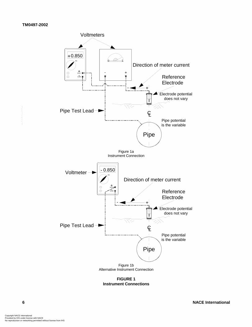
5.1 Instruments used to measure AC voltage, direct current(DC) voltage, or other electrical functions usually have oneterminal designated “Common” (COM). This terminal eitheris black in color or has a negative (-) symbol. The positiveterminal either is red in color or has a positive (+) symbol.The positive and negative symbols in the meter displayindicate the current flow direction through the instrument(Figure 1a). For example, a positive symbol in the meterdisplay indicates current flowing from the positive terminalthrough the meter to the negative terminal. One instrumenttest lead is usually black in color and the other red. Theblack test lead is connected to the negative terminal of theinstrument and the red lead to the positive terminal.
5.2 Voltage measurements should be made using thelowest practicable range on the instrument. A voltagemeasurement is more accurate when it is measured in theupper two-thirds of a range selected for a particularinstrument. Errors can occur, for example, when aninstrument with a 2-V range is used to measure a voltage of15 mV. Such a value might be a voltage drop caused bycurrent flowing in a metal pipeline or through a calibratedshunt. A much more accurate measurement would bemade using an instrument having a 20-mV range.
5.3 The usual technique to determine the DC voltageacross battery terminals, pipeline metal/electrolyte interface,or other DC system is to connect the black test lead to thenegative side of the circuit and the red test lead to thepositive side of the circuit. When connected in this manner,an analog instrument needle moves in an upscale
--`,,,,,-`-`,,`,,`,`,,`---
(clockwise) direction indicating a positive value with relationto the negative terminal. A digital instrument connected inthe same manner displays a digital value, usually precededby a positive symbol. In each situation the measuredvoltage is positive with respect to the instrument’s negativeterminal. (See instrument connections in Figure 1a.)
5.4 The voltage present between a reference electrode anda metal pipe can be measured with a voltmeter. Thereference electrode potential is normally positive withrespect to ferrous pipe; conversely the ferrous pipe isnegative with respect to the reference electrode.
5.5 A pipe-to-electrolyte potential is measured using a DCvoltmeter having an appropriate input impedance (orinternal resistance, for an analog instrument), voltagerange(s), test leads, and a stable reference electrode, suchas a saturated copper/copper sulfate (CSE), silver/silverchloride (Ag/AgCl), or saturated potassium chloride (KCl)calomel reference electrode. The CSE is usually used formeasurements when the electrolyte is soil or fresh waterand less often for salt water. When a CSE is used in ahigh-chloride environment, the stability (lack ofcontamination) of the CSE must be determined before thereadings may be considered valid. The Ag/AgCl referenceelectrode is usually used in seawater environments. Thesaturated KCl calomel electrode is used more often forlaboratory work. However, more-rugged, polymer-body,gel-filled saturated KCl calomel electrodes are available,though modifications may be necessary to increase contactarea with the environment.
NACE International
r Resale
CPN
TM0497-2002
5.6 Meter Polarity
5.6.1 Pipe-to-electrolyte potentials are usuallymeasured by connecting the instrument negativeterminal to the pipe and the positive terminal to thereference electrode, which is in contact with the pipeelectrolyte. With this connection the instrumentindicates that the reference electrode is positive withrespect to the pipe. Because the reference electrodehas a positive value with respect to the pipe, the pipevoltage is negative with respect to the referenceelectrode (see Figure 1a). This negative pipe-to-electrolyte potential is the value used for NACE criteria.
5.6.2 Pipe-to-electrolyte potential measurements aresometimes made with the reference electrodeconnected to the instrument negative terminal and thepipeline to the positive terminal. Figure 1b illustratesthis connection.
5.6.2.1 If the instrument is a data logging device,the recorded data may be printed out with anegative symbol unless a polarity reversal occurs.
5.7 The pipe-to-electrolyte potential measurement of aburied pipe should be made with the reference electrodeplaced close to the metal/electrolyte interface of the pipe.The common practice, however, is to place the referenceelectrode as close to the pipe as practicable, which isusually at the surface of the earth above the centerline ofthe pipe. (See Figure 1a.) This measurement includes acombination of the voltage drops associated with the:
(a) Voltmeter;(b) Test leads;(c) Reference electrode;(d) Electrolyte;(e) Coating, if applied;(f) Pipe; and(g) Pipe metal/electrolyte interface.
5.8 The pipe-to-electrolyte potential measurement asdescribed above is a resultant of the:
(a) Voltage drop created by current flowing through theelectrical resistances of the items listed in Paragraph 5.7;and(b) For coated pipe, the influence of coating holidays,depending on their location, number, and size.
5.9 Pipe-to-electrolyte potential measurements made todetermine the level of cathodic protection at the test siteshould consider the following:
(a) Effectiveness of coatings, particularly those known orsuspected to be deteriorated or damaged;(b) Bare sections of pipe;(c) Bonds to mitigate interference;(d) Parallel coated pipelines, electrically connected andpolarized to different potentials;(e) Shielding;
opyright NACE International rovided by IHS under license with NACE
Not foo reproduction or networking permitted without license from IHS
(f) Effects of other structures on the measurements;(g) History of corrosion leaks and repairs;(h) Location of impressed current anodes;(i) Unknown, inaccessible, or direct-connected galvanicanodes;(j) Location of isolation devices, including high-resistancepipe connections and compression couplings;(k) Presence of electrolytes, such as unusual corrosives,chemical spills, extreme soil resistivity changes, acidicwaters, and contamination from sewer spills;(l) Location of shorted or isolated casings;(m) DC interference currents, such as HVDC, telluric,welding equipment, foreign rectifier, mining equipment, andelectric railway or transit systems;(n) Contacts with other metals or structures;(o) Locations where the pipe enters and leaves theelectrolyte;(p) Areas of construction activity during the pipelinehistory;(q) Underground metallic structures close to or crossingthe pipeline;(r) Valves and other appurtenances; and(s) HVAC overhead power lines.
5.10 Voltage drops other than those across the pipemetal/electrolyte interface shall be considered for validinterpretation of pipe-to-electrolyte voltage measurementsmade to satisfy a criterion. Measurement errors should beminimized to ensure reliable pipe-to-electrolyte potentialmeasurements.
5.11 The effect of voltage drops on a pipe-to-electrolytepotential measurement can be determined by interruptingall significant current sources and then making themeasurement. This measurement is referred to as an“instant-off” potential. The measurement must be madewithout perceptible delay after current interruption to avoidloss of polarization. The voltage value measured isconsidered to be the “polarized potential” of the pipe at thatlocation. Because the current interruption may cause avoltage spike, recording the spike as the “instant-offpotential” must be avoided. The magnitude and duration ofthe voltage spike can vary; however, the duration is usuallywithin 0.5 second. The following are examples of when itmay not be practical to interrupt all current sources to makethe “instant-off potential” measurement.
5.11.1 Galvanic Anodes
5.11.1.1 Galvanic anodes connected directly tothe pipe without benefit of aboveground teststations or connections. Interruption requiresexcavation of the connections.
5.11.2 Impressed Current Systems
5.11.2.1 Galvanic anodes directly connected topiping protected using an impressed currentsystem;
5.11.2.2 Multiple impressed current sources;
NACE International 5--`,,,,,-`-`,,`,,`,`,,`---
r Resale
CPN
TM0497-2002
6 NACE International
-
DC
VOLT
COM
+
-
0.850
+
Pipe Test Lead
Voltmeters
+-
Direction of meter current+
ReferenceElectrode
CL
Electrode potentialdoes not vary
Pipe potentialis the variable
Pipe
0 1
Figure 1aInstrument Connection
Pipe Test Lead
Voltmeter
+-
Direction of meter current
ReferenceElectrode
CL
Electrode potentialdoes not vary
Pipe potentialis the variable
Pipe
DC
VOLT
COM
-
-
0.850
+
Figure 1bAlternative Instrument Connection
FIGURE 1Instrument Connections
opyright NACE International rovided by IHS under license with NACE
--`,,,,,-`-`,,`,,`,`,,`---
Not for Resaleo reproduction or networking permitted without license from IHS
CoPrNo
TM0497-2002
pyriovid rep
5.11.2.3 Impressed current devices on foreignpiping; and
5.11.2.4 Numerous cross bonds to parallelpipelines.
5.11.3 Natural and Manmade Stray Currents
5.11.3.1 Telluric currents; and
5.11.3.2 Manmade DC stray currents, such asthose from mass transit and mining operations.
5.12 When voltage drops have been evaluated at a testlocation and the pipe-to-electrolyte potential found to besatisfactory, the “on” pipe-to-electrolyte potential value maybe used for monitoring until significant environmental,structural, or cathodic protection system parameterschange.
ght NACE International ed by IHS under license with NACE
Noroduction or networking permitted without license from IHS
5.12.1 Significant environmental, structural, orcathodic protection system parameter changes mayinclude:
(a) Replacement or addition of piping;(b) Addition, relocation, or deterioration of cathodicprotection systems;(c) Failure of electrical isolating devices;(d) Effectiveness of coatings; and(e) Influence of foreign structures.
5.13 After a cathodic protection system is operating, timemay be required for the pipe to polarize. This should beconsidered when measuring the potential at a test site on anewly protected pipe or after reenergizing a cathodicprotection device.
________________________________________________________________________
Section 6: Causes of Measurement Errors
6.1 Factors that contribute to faulty potentialmeasurements include:
6.1.1 Pipe and instrument test leads
(a) Broken or frayed wire strands (may not be visibleinside the insulation);(b) Damaged or defective test lead insulation thatallows the conductor to contact wet vegetation, theelectrolyte, or other objects;(c) Loose, broken, or faulty pipe or instrumentconnections; and(d) Dirty or corroded connection points.
6.1.2 Reference electrode condition and placement
(a) Contaminated reference electrode solution orrod, and solutions of insufficient quantity or saturation(only laboratory-grade chemicals and distilled water, ifwater is required, should be used in a referenceelectrode);(b) Reference electrode plug not sufficiently porousto provide a conductive contact to the electrolyte;(c) Porous plug contaminated by asphalt, oil, orother foreign materials;(d) High-resistance contact between referenceelectrode and dry or frozen soil, rock, gravel,vegetation, or paving material;(e) Reference electrode placed in the potentialgradient of an anode;(f) Reference electrode positioned in the potentialgradient of a metallic structure other than the one withthe potential being measured;(g) Electrolyte between pipe and disbonded coatingcausing error due to electrode placement in electrolyteon opposite side of coating;
t for R
(h) Defective permanently installed referenceelectrode;(i) Temperature correction not applied whenneeded; and(j) Photo-sensitive measurement error (in CSE witha clear-view window) due to light striking the electrodeelectrolyte solution (photovoltaic effect).
6.1.3 Unknown isolating devices, such as unbondedtubing or pipe compression fittings, causing the pipe tobe electrically discontinuous between the testconnection and the reference electrode location.
6.1.4 Parallel path inadvertently established by testpersonnel contacting instrument terminals or metallicparts of the test lead circuit, such as test lead clips andreference electrodes, while a potential measurement isbeing made.
6.1.5 Defective or inappropriate instrument, incorrectvoltage range selection, instrument not calibrated orzeroed, or a damp instrument sitting on wet earth.
6.1.6 Instrument having an analog-to-digital converteroperating at such a fast speed that the voltage spikesproduced by current interruption are indicated insteadof the actual “on” and “off” values.
6.1.7 Polarity of the measured value incorrectlyobserved.
6.1.8 Cathodic protection current-carrying conductorused as a test lead for a pipe potential measurement.
NACE International 7
--`,,,,,-`-`,,`,,`,`,,`---
esale

TM0497-2002
CPN
6.1.9 Interference
6.1.9.1 Electromagnetic interference or inductionresulting from AC power lines or radio frequencytransmitters inducing test lead and/or instrumenterrors. This condition is often indicated by a fuzzy,fluctuating, or blurred pointer movement on ananalog instrument or erratic displays on digitalvoltmeters. A DC voltmeter must have sufficientAC rejection capability, which can be determinedby referring to the manufacturer’s specification.
6.1.9.2 Telluric or stray DC currents flowingthrough the earth and piping.
6.2 Reference electrode contact resistance is reduced by:
6.2.1 Soil moisture—If the surface soil is so dry thatthe electrical contact of the reference electrode with the
opyright NACE International rovided by IHS under license with NACE
Not foo reproduction or networking permitted without license from IHS
electrolyte is impaired, the soil around the electrodemay be moistened with water until the contact isadequate.
6.2.2 Contact surface area—Contact resistance maybe reduced by using a reference electrode with a largercontact surface area.
6.2.3 Frozen soil—Contact resistance may be reducedby removing the frozen soil to permit electrode contactwith unfrozen soil.
6.2.4 Concrete or asphalt-paved areas—Contactresistance may be reduced by drilling through thepaving to permit electrode contact with the soil.
________________________________________________________________________
Section 7: Voltage Drops Other Than Across the Pipe Metal/Electrolyte Interface
7.1 Voltage drops that are present when pipe-to-electrolytepotential measurements are made occur in the following:
7.1.1 Measurement Circuit—The voltage drop otherthan across the pipe metal/electrolyte interface in themeasurement circuit is the sum of the individualvoltage drops caused by the meter current flow throughindividual resistances that include:
(a) Instrument test lead and connection resistances;(b) Reference electrode internal resistance;(c) Reference electrode-to-electrolyte contactresistance;(d) Coating resistance;(e) Pipe metallic resistance;(f) Electrolyte resistance;(g) Analog meter internal resistance; and(h) Digital meter internal impedance.A measurement error occurs if the analog meterinternal resistance or the digital meter internalimpedance is not several orders of magnitude higherthan the sum of the other resistances in themeasurement circuit.
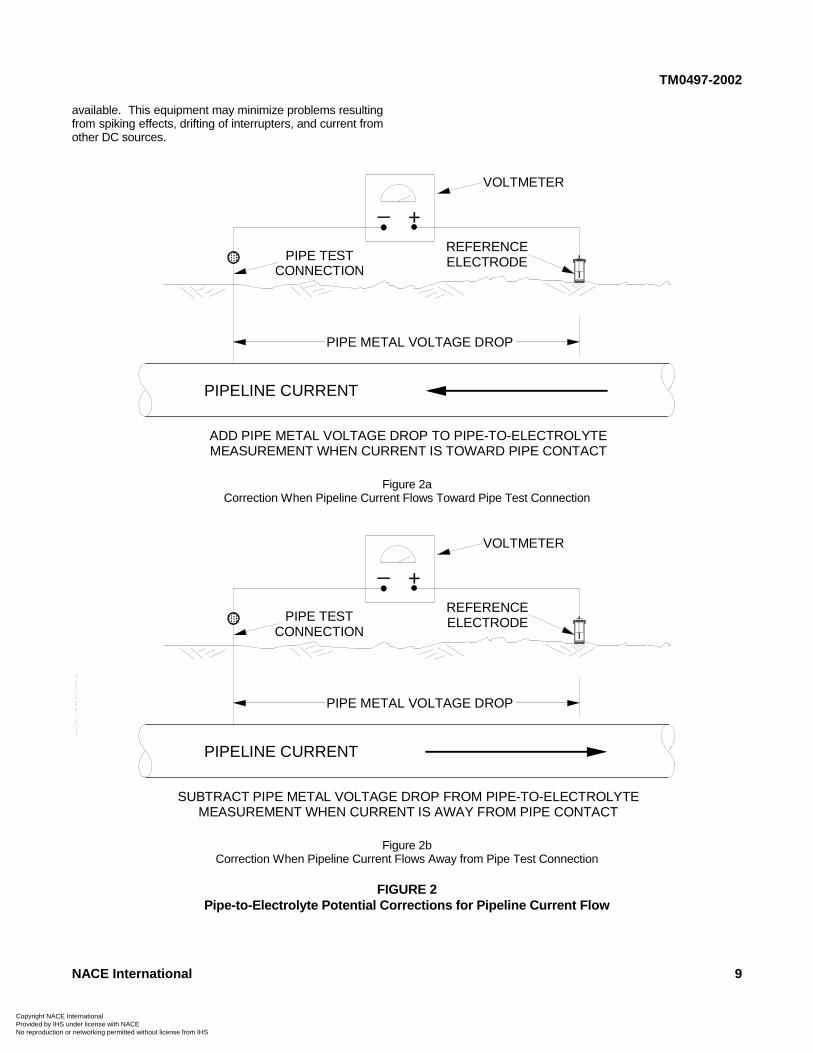
7.1.2 Pipe—Current flowing within the pipe wallcreates a voltage drop. This voltage drop and thedirection of the current shall be considered when thereference electrode is not near the pipe connection andsignificant current is conducted by the pipe.Consideration is needed because an error in the pipe-to-electrolyte potential measurement will occur if thepipe current causes a significant voltage drop. Currentdirected to the pipe connection from the referenceelectrode causes the measured potential to be morenegative by the amount of the pipe current voltage drop(see Figure 2a). Conversely, the potential is lessnegative by that amount if the pipe current direction is
from the pipe connection to the reference electrode(see Figure 2b).
7.1.3 Electrolyte—When a pipe-to-electrolyte potentialis measured with cathodic protection current applied,the voltage drop in the electrolyte between thereference electrode and the metal/electrolyte interfaceshall be considered. Measurements taken close tosacrificial or impressed current anodes can contain alarge voltage drop. Such a voltage drop can consist of,but is not limited to, the following:
(a) A voltage drop caused by current flowing tocoating holidays when the line is coated; and(b) A voltage drop caused by large voltage gradientsin the electrolyte that occur near operating anodes(sometimes termed “raised earth effect”).
7.1.3.1 Testing to locate galvanic anodes bymoving the reference electrode along thecenterline of the line may be necessary when thelocations are not known.
7.1.4 Coatings—Most coatings provide protection tothe pipe by reducing the pipe surface contact with theenvironment. Due to the relative ionic impermeabilityof coatings, they resist current flow. While theinsulating ability of coatings reduces the currentrequired for cathodic protection, coatings are notimpervious to current flowing through them. Currentflow through the coating causes a voltage drop that isgreater than when the pipe is bare, under the sameenvironmental conditions.
7.2 Specialized equipment that uses various techniques tomeasure the impressed current wave form and to calculatea pipe-to-electrolyte potential free of voltage drop is
8 NACE International--`,,,,,-`-`,,`,,`,`,,`---
r Resale
TM0497-2002
available. This equipment may minimize problems resultingfrom spiking effects, drifting of interrupters, and current fromother DC sources.
NACE International 9
+_
PIPE METAL VOLTAGE DROP
PIPELINE CURRENT
PIPE TESTCONNECTION
REFERENCEELECTRODE
VOLTMETER
ADD PIPE METAL VOLTAGE DROP TO PIPE-TO-ELECTROLYTEMEASUREMENT WHEN CURRENT IS TOWARD PIPE CONTACT
Figure 2aCorrection When Pipeline Current Flows Toward Pipe Test Connection
+_
PIPE METAL VOLTAGE DROP
PIPELINE CURRENT
PIPE TESTCONNECTION
REFERENCEELECTRODE
VOLTMETER
SUBTRACT PIPE METAL VOLTAGE DROP FROM PIPE-TO-ELECTROLYTEMEASUREMENT WHEN CURRENT IS AWAY FROM PIPE CONTACT
Figure 2bCorrection When Pipeline Current Flows Away from Pipe Test Connection
FIGURE 2Pipe-to-Electrolyte Potential Corrections for Pipeline Current Flow
Copyright NACE International Provided by IHS under license with NACE
--`,,,,,-`-`,,`,,`,`,,`---
Not for ResaleNo reproduction or networking permitted without license from IHS
CPN
TM0497-2002
________________________________________________________________________
Section 8: Test Method 1—Negative 850 mV Pipe-to-Electrolyte Potentialof Steel and Cast Iron Piping with Cathodic Protection Applied
--`,,,,,
oprovo r
-`
8.1 Scope
Test Method 1 describes a procedure to assess theadequacy of cathodic protection on a steel or cast ironpipeline according to the criterion stated in NACE StandardRP0169,1 Paragraph 6.2.2.1.1:
A negative (cathodic) potential of at least 850 mV withthe cathodic protection applied. This potential ismeasured with respect to a saturated copper/coppersulfate reference electrode (CSE) contacting theelectrolyte. Voltage drops other than those across thestructure-to-electrolyte boundary must be consideredfor valid interpretation of this voltage measurement.
NOTE: Consideration is understood to mean theapplication of sound engineering practice indetermining the significance of voltage drops bymethods such as:
(a) Measuring or calculating the voltage drop(s);(b) Reviewing the historical performance of thecathodic protection system;(c) Evaluating the physical and electricalcharacteristics of the pipe and its environment; and(d) Determining whether there is physical evidence ofcorrosion.
8.2 General
8.2.1 Cathodic protection current shall remain “on”during the measurement process. This potential iscommonly referred to as the “on” potential.
8.2.2 Test Method 1 measures the pipe-to-electrolytepotential as the sum of the polarized potential and anyvoltage drops in the circuit. These voltage dropsinclude those through the electrolyte and pipelinecoating from current sources such as impressedcurrent, galvanic anodes, and telluric effects.
8.2.3 Because voltage drops other than those acrossthe pipe metal/electrolyte interface may be included inthis measurement, these drops shall be considered, asdiscussed in Paragraph 8.6.
8.3 Comparison with Other Methods
8.3.1 Advantages
(a) Minimal equipment, personnel, and vehicles arerequired; and(b) Less time is required to make measurements.
-`,,`,,`,`,,`---
yright NACE International ided by IHS under license with NACE
Not feproduction or networking permitted without license from IHS
8.3.2 Disadvantages
(a) Potential measured includes voltage drops otherthan those across the pipe metal/electrolyte interface;and(b) Meeting the requirements for considering thesignificance of voltage drops (see Paragraph 8.6) canresult in added time to assess adequacy of cathodicprotection at the test site.
8.4 Basic Test Equipment
8.4.1 Voltmeter with adequate input impedance.Commonly used digital instruments have a nominalimpedance of 10 megaohms. An analog instrumentwith an internal resistance of 100,000 ohms per voltmay be adequate in certain circumstances in which thecircuit resistance is low. A potentiometer circuit may benecessary in other instances.
8.4.2 Two color-coded meter leads with clips forconnection to the pipeline and reference electrode.
8.4.3 Reference Electrode
8.4.3.1 CSE.
8.4.3.2 Other standard reference electrodes maybe substituted for the CSE. These referenceelectrodes are described in Appendix A,Paragraph A2.
8.5 Procedure
8.5.1 Before the test, verify that cathodic protectionequipment has been installed and is operatingproperly. Time should be allowed for the pipelinepotentials to reach polarized values.
8.5.2 Determine the location of the site to be tested.Selection of a site may be based on:
(a) Location accessible for future monitoring;(b) Other protection systems, structures, and anodesthat may influence the pipe-to-electrolyte potential;(c) Electrical midpoints between protective devices;(d) Known location of an ineffective coating if the lineis coated; and(e) Location of a known or suspected corrosiveenvironment.
8.5.3 Make electrical contact between the referenceelectrode and the electrolyte at the test site, directlyover the centerline of the pipeline or as close to it as ispracticable.
10 NACE International
or Resale
CopyrighProvidedNo repro
TM0497-2002
8.5.4 Connect the voltmeter to the pipeline andreference electrode as described in Paragraph 5.6.
8.5.5 Record the pipe-to-electrolyte potential and itspolarity with respect to the reference electrode.
8.6 Considering the Significance of Voltage Drops for ValidInterpretation of the Criterion
8.6.1 The significance of voltage drops can beconsidered by:
8.6.1.1 Comparing historical levels of cathodicprotection with physical evidence from the pipelineto determine whether corrosion has occurred.
8.6.1.2 Comparing soil corrosiveness withphysical evidence from the pipeline to determinewhether corrosion has occurred.
8.6.2 Physical evidence of corrosion is determined byevaluating items such as:
(a) Leak history data;
--`,,,,,-`-`,,`,,`,`,,`---
t NACE International by IHS under license with NACE
Noduction or networking permitted without license from IHS
(b) Buried pipeline inspection report data regardinglocations of coating failures, localized conditions ofmore-corrosive electrolyte, or substandard cathodicprotection levels have been experienced; and/or(c) Verification of in-line inspection-tool metal lossindications by follow-up excavation of anomalies andinspection of the pipe external surface.
8.6.3 Cathodic protection shall be judged adequate atthe test site if:
(a) The pipe-to-electrolyte potential measurement isnegative 850 mV, or more negative, with respect to aCSE; and(b) The significance of voltage drops has beenconsidered by applying the principles described inParagraphs 8.6.1 or 8.6.2.
8.7 Monitoring
When the significance of a voltage drop has beenconsidered at the test site, the measured potentials may beused for monitoring unless significant environmental,structural, coating integrity, or cathodic protection systemparameters have changed.
________________________________________________________________________
Section 9: Test Method 2—Negative 850 mV Polarized Pipe-to-ElectrolytePotential of Steel and Cast Iron Piping
9.1 Test Method 2 describes the most commonly used testmethod to satisfy this criterion (see Paragraph 9.2). Thismethod uses current interruption to determine whethercathodic protection is adequate at the test site according tothe criterion.
9.2 Scope
This method uses an interrupter(s) to eliminate the cathodicprotection system voltage drop from the pipe-to-electrolytepotential measurement for comparison with the criterionstated in NACE Standard RP0169,1 Paragraph 6.2.2.1.2:
A negative polarized potential of at least 850 mVrelative to a saturated copper/copper sulfate referenceelectrode (CSE).
9.3 General
9.3.1 Interrupting the known cathodic protectioncurrent source(s) eliminates voltage drops associatedwith the protective currents being interrupted.However, significant voltage drops may also occurbecause of currents from other sources, as discussedin Section 7.
9.3.2 To avoid significant depolarization of the pipe,the “off” period should be limited to the time necessary
to make an accurate potential measurement. The “off”period is typically less than 3 seconds.
9.3.3 The magnitude and duration of a voltage spikecaused by current interruption can vary, but theduration is typically within 0.5 second. After the currentis interrupted, the time elapsed until the measurementis recorded should be long enough to avoid errorscaused by voltage spiking. On-site measurements withappropriate instruments may be necessary todetermine the duration and magnitude of the spiking.
9.3.4 Current sources that can affect the accuracy ofthis test method include the following:
(a) Unknown, inaccessible, or direct-connectedgalvanic anodes;(b) Cathodic protection systems on associatedpiping or foreign structures;(c) Electric railway systems;(d) HVDC electric power systems;(e) Telluric currents;(f) Galvanic, or bimetallic, cells;(g) DC mining equipment;(h) Parallel coated pipelines, electrically connectedand polarized to different potentials;(i) Uninterrupted current sources;(j) Unintentional connections to other structures orbonds to mitigate interference; and(k) Long-line currents.
NACE International 11
t for Resale
CPN
TM0497-2002
oproo
9.4 Comparison with Other Methods
9.4.1 Advantages
(a) Voltage drops associated with the protectivecurrents being interrupted are eliminated.
9.4.2 Disadvantages
(a) Additional equipment is required;(b) Additional time, personnel, and vehicles may berequired to set up equipment and to make pipe-to-electrolyte potential measurements; and(c) Test results are difficult or impossible to analyzewhen stray currents are present or direct-connectedgalvanic anodes or foreign impressed current devicesare present and cannot be interrupted.
9.5 Basic Test Equipment
9.5.1 Voltmeter with adequate input impedance.Commonly used digital instruments have a nominalimpedance of 10 megaohms. An analog instrumentwith an internal resistance of 100,000 ohms per voltmay be adequate in certain circumstances in which thecircuit resistance is low. A potentiometer circuit may benecessary in other instances.
9.5.2 Two color-coded meter leads with clips forconnection to the pipeline and reference electrode.
9.5.3 Sufficient current interrupters to interruptinfluential cathodic protection current sourcessimultaneously.
9.5.4 Reference electrode
9.5.4.1 CSE.
9.5.4.2 Other standard reference electrodes maybe substituted for the CSE. These referenceelectrodes are described in Appendix A,Paragraph A2.
9.6 Procedure
9.6.1 Before the test, verify that cathodic protectionequipment has been installed and is operatingproperly. Time should be allowed for the pipelinepotentials to reach polarized values.
9.6.2 Install and place in operation necessaryinterrupter equipment in all significant DC sources
yright NACE International vided by IHS under license with NACE
Noreproduction or networking permitted without license from IHS
protecting the pipe at the test site, and place inoperation with a synchronized and/or known “off” and“on” cycle. The “off” cycle should be kept as short aspossible but still long enough to read a polarized pipe-to-electrolyte potential after any “spike” as shown inFigure 3a has collapsed.
9.6.3 Determine the location of the site to be tested.Selection of a site may be based on:
(a) Location accessible for future monitoring;(b) Other protection systems, structures, and anodesthat may influence the pipe-to-electrolyte potential;(c) Electrical midpoints between protection devices;(d) Known location of an ineffective coating whenthe pipeline is coated; and(e) Location of a known or suspected corrosiveenvironment.
9.6.4 Make electrical contact between the referenceelectrode and the electrolyte at the test site, directlyover the centerline of the pipeline or as close to it as ispracticable.
9.6.5 Connect voltmeter to the pipeline and referenceelectrode as described in Paragraph 5.6.
9.6.5.1 If spiking may be present, use anappropriate instrument, such as an oscilloscope orhigh-speed recording device, to verify that themeasured values are not influenced by a voltagespike.
9.6.6 Record the pipe-to-electrolyte “on” and “off”potentials and their polarities with respect to thereference electrode.
9.7 Evaluation of Data
Cathodic protection shall be judged adequate at the test siteif the polarized pipe-to-electrolyte potential is negative 850mV, or more negative, with respect to a CSE.
9.8 Monitoring
When the polarized pipe-to-electrolyte potential has beendetermined to equal or exceed a negative 850 mV, thepipeline “on” potential may be used for monitoring unlesssignificant environmental, structural, coating integrity, orcathodic protection system parameters have changed.
--`,,,,,-`-`,,`,,`,`,,`---
12 NACE International
t for Resale
CopyriProvidNo rep
TM0497-2002
________________________________________________________________________
Section 10: Test Method 3—100 mV Cathodic Polarizationof Steel, Cast Iron, Aluminum, and Copper Piping
ger
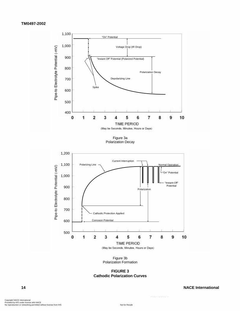
10.1 Test Method 3 describes the use of either pipelinepolarization decay or pipeline polarization formation todetermine whether cathodic protection is adequate at thetest site according to the criterion. Consequently, this testmethod consists of two mutually independent parts, TestMethods 3a and 3b, that describe the procedures fortesting. Cathodic polarization curves for Test Methods 3aand 3b are shown in Figure 3. These are schematicdrawings of generic polarization decay and formation.
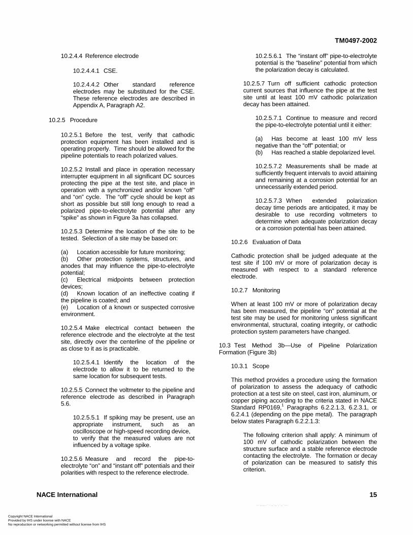
10.2 Test Method 3a — Use of Pipeline Polarization Decay(Figure 3a)
10.2.1 Scope
This method uses pipeline polarization decay to assessthe adequacy of cathodic protection on a steel, castiron, aluminum, or copper pipeline according to thecriterion stated in NACE Standard RP0169,1 Paragraph6.2.2.1.3, 6.2.3.1, or 6.2.4.1 (depending on the pipemetal). The paragraph below states Paragraph6.2.2.1.3:
The following criterion shall apply: A minimum of100 mV of cathodic polarization between thestructure surface and a stable reference electrodecontacting the electrolyte. The formation or decayof polarization can be measured to satisfy thiscriterion.
10.2.2 General
10.2.2.1 Interrupting the known cathodicprotection source(s) eliminates voltage dropsassociated with the protective current(s) beinginterrupted.
10.2.2.2 Other current sources that can affect theaccuracy of this test method include the following:
(a) Unknown, inaccessible, or direct-connectedgalvanic anodes;(b) Cathodic protection systems on associatedpiping or foreign structures;(c) Electric railway systems;(d) HVDC electric power systems;(e) Telluric currents;(f) Galvanic, or bimetallic, cells;(g) DC mining equipment;(h) Parallel coated pipelines, electricallyconnected and polarized to different potentials;(i) Uninterrupted current sources;(j) Unintentional connections to other structuresor bonds to mitigate interference; and(k) Long-line currents.
ht NACE International d by IHS under license with NACE
Not for Reoduction or networking permitted without license from IHS
--`,,,,,-`-`,,`,,`,`,,`--
10.2.2.3 The magnitude and duration of a voltagespike caused by current interruption can vary, butthe duration is typically within 0.5 second. Afterthe current is interrupted, the time elapsed until themeasurement is recorded should be long enoughto avoid errors caused by voltage spiking. On-sitemeasurements with appropriate instruments maybe necessary to determine the duration andmagnitude of the spiking.
10.2.3 Comparison with Other Methods
10.2.3.1 Advantages
(a) This method is especially useful for bare orineffectively coated pipe; and(b) This method is advantageous whencorrosion potentials may be low (for example, 500mV or less negative) and/or the current required tomeet a negative 850 mV polarized potentialcriterion would be considered excessive.
10.2.3.2 Disadvantages
(a) Additional equipment is required;(b) Additional time, personnel, and vehicles maybe required to set up equipment and to make pipe-to-electrolyte potential measurements; and(c) Test results are difficult or impossible toanalyze when direct-connected galvanic anodes orforeign impressed current devices are present andcannot be interrupted, or when stray currents arepresent.
10.2.4 Basic Test Equipment
10.2.4.1 Voltmeter with adequate inputimpedance. Commonly used digital instrumentshave a nominal impedance of 10 megaohms. Ananalog instrument with an internal resistance of100,000 ohms per volt may be adequate in certaincircumstances in which the circuit resistance islow. A potentiometer circuit may be necessary inother instances.
10.2.4.1.1 Recording voltmeters can beuseful to record polarization decay.
10.2.4.2 Two color-coded meter leads with clipsfor connection to the pipeline and referenceelectrode.
10.2.4.3 Sufficient current interrupters to interruptinfluential cathodic protection current sourcessimultaneously.
NACE International 13
sale
-
TM0497-2002
14 NACE International
Spike
"On" Potential
"Instant Off" Potential (Polarized Potential)
Depolarizing Line
Voltage Drop (IR Drop)
Polarization Decay
Figure 3aPolarization Decay
Normal Operation
"On" Potential
Current Interruption
"Instant-Off"Potential
Polarization
Cathodic Protection Applied
Corrosion Potential
Polarizing Line
Figure 3bPolarization Formation
FIGURE 3Cathodic Polarization Curves
1,200
1,100
1,000
900
800
700
600
500
1,100
1,000
900
800
700
600
500
400
Copyright NACE International Provided by IHS under license with NACE
--`,,,,,-`-`,,`,,`,`,,`---
Not for ResaleNo reproduction or networking permitted without license from IHS
CoProNo
TM0497-2002
pyv re
10.2.4.4 Reference electrode
10.2.4.4.1 CSE.
10.2.4.4.2 Other standard referenceelectrodes may be substituted for the CSE.These reference electrodes are described inAppendix A, Paragraph A2.
10.2.5 Procedure
10.2.5.1 Before the test, verify that cathodicprotection equipment has been installed and isoperating properly. Time should be allowed for thepipeline potentials to reach polarized values.
10.2.5.2 Install and place in operation necessaryinterrupter equipment in all significant DC sourcesprotecting the pipe at the test site, and place inoperation with a synchronized and/or known “off”and “on” cycle. The “off” cycle should be kept asshort as possible but still long enough to read apolarized pipe-to-electrolyte potential after any“spike” as shown in Figure 3a has collapsed.
10.2.5.3 Determine the location of the site to betested. Selection of a site may be based on:
(a) Location accessible for future monitoring;(b) Other protection systems, structures, andanodes that may influence the pipe-to-electrolytepotential;(c) Electrical midpoints between protectiondevices;(d) Known location of an ineffective coating ifthe pipeline is coated; and(e) Location of a known or suspected corrosiveenvironment.
10.2.5.4 Make electrical contact between thereference electrode and the electrolyte at the testsite, directly over the centerline of the pipeline oras close to it as is practicable.
10.2.5.4.1 Identify the location of theelectrode to allow it to be returned to thesame location for subsequent tests.
10.2.5.5 Connect the voltmeter to the pipeline andreference electrode as described in Paragraph5.6.
10.2.5.5.1 If spiking may be present, use anappropriate instrument, such as anoscilloscope or high-speed recording device,to verify that the measured values are notinfluenced by a voltage spike.
10.2.5.6 Measure and record the pipe-to-electrolyte “on” and “instant off” potentials and theirpolarities with respect to the reference electrode.
right NACE International ided by IHS under license with NACE
Not forproduction or networking permitted without license from IHS
10.2.5.6.1 The “instant off” pipe-to-electrolytepotential is the “baseline” potential from whichthe polarization decay is calculated.
10.2.5.7 Turn off sufficient cathodic protectioncurrent sources that influence the pipe at the testsite until at least 100 mV cathodic polarizationdecay has been attained.
10.2.5.7.1 Continue to measure and recordthe pipe-to-electrolyte potential until it either:
(a) Has become at least 100 mV lessnegative than the “off” potential; or(b) Has reached a stable depolarized level.
10.2.5.7.2 Measurements shall be made atsufficiently frequent intervals to avoid attainingand remaining at a corrosion potential for anunnecessarily extended period.
10.2.5.7.3 When extended polarizationdecay time periods are anticipated, it may bedesirable to use recording voltmeters todetermine when adequate polarization decayor a corrosion potential has been attained.
10.2.6 Evaluation of Data
Cathodic protection shall be judged adequate at thetest site if 100 mV or more of polarization decay ismeasured with respect to a standard referenceelectrode.
10.2.7 Monitoring
When at least 100 mV or more of polarization decayhas been measured, the pipeline “on” potential at thetest site may be used for monitoring unless significantenvironmental, structural, coating integrity, or cathodicprotection system parameters have changed.
10.3 Test Method 3b—Use of Pipeline PolarizationFormation (Figure 3b)
10.3.1 Scope
This method provides a procedure using the formationof polarization to assess the adequacy of cathodicprotection at a test site on steel, cast iron, aluminum, orcopper piping according to the criteria stated in NACEStandard RP0169,1 Paragraphs 6.2.2.1.3, 6.2.3.1, or6.2.4.1 (depending on the pipe metal). The paragraphbelow states Paragraph 6.2.2.1.3:
The following criterion shall apply: A minimum of100 mV of cathodic polarization between thestructure surface and a stable reference electrodecontacting the electrolyte. The formation or decayof polarization can be measured to satisfy thiscriterion.
NACE International 15--`,,,,,-`-`,,`,,`,`,,`---
Resale
CPN
TM0497-2002
oroo
10.3.2 General
Ferrous, aluminum, and copper pipelines may beadequately cathodically protected if applying cathodicprotection causes a polarization change of 100 mV ormore with respect to a reference potential.
10.3.2.1 Current sources that can affect theaccuracy of this test method include the following:
(a) Unknown, inaccessible, or direct-connectedgalvanic anodes;(b) Cathodic protection systems on associatedpiping or foreign structures;(c) Electric railway systems;(d) HVDC electric power systems;(e) Telluric currents;(f) Galvanic, or bimetallic, cells;(g) DC mining equipment;(h) Parallel coated pipelines, electricallyconnected and polarized to different potentials;(i) Uninterrupted current sources;(j) Unintentional connections to other structuresor bonds to mitigate interference; and(k) Long-line currents.
10.3.3 Comparison with Other Methods
10.3.3.1 Advantages
(a) This method is especially useful for bare orineffectively coated pipe; and(b) This method is advantageous whencorrosion potentials may be low (for example, 500mV or less negative) and/or the current required tomeet a negative 850 mV potential criterion wouldbe considered excessive.
10.3.3.2 Disadvantages
(a) Additional equipment is required;(b) Additional time, personnel, and vehicles maybe required to set up equipment and to make thepipe-to-electrolyte potential measurements; and(c) Test results are difficult or impossible toanalyze when stray currents are present or whendirect-connected galvanic anodes or foreignimpressed currents are present and cannot beinterrupted.
10.3.4 Basic Test Equipment
10.3.4.1 Voltmeter with adequate inputimpedance. Commonly used digital instrumentshave a nominal impedance of 10 megaohms. Ananalog instrument with an internal resistance of100,000 ohms per volt may be adequate in certaincircumstances in which the circuit resistance islow. A potentiometer circuit may be necessary inother instances.
pyright NACE International vided by IHS under license with NACE
Not for R reproduction or networking permitted without license from IHS
10.3.4.2 Two color-coded meter leads with clipsfor connection to the pipeline and referenceelectrode.
10.3.4.3 Sufficient current interrupters to interruptinfluential cathodic protection current sourcessimultaneously.
10.3.4.4 Reference electrode
10.3.4.4.1 CSE.
10.3.4.4.2 Other standard referenceelectrodes may be substituted for the CSE.These reference electrodes are described inAppendix A, Paragraph A2.
10.3.5 Procedure
10.3.5.1 Before the test, verify that cathodicprotection equipment has been installed but is notoperating.
10.3.5.2 Determine the location of the site to betested. Selection of a site may be based on:
(a) Location accessible for future monitoring;(b) Other protection systems, structures, andanodes that may influence the pipe-to-electrolytepotential;(c) Electrical midpoints between protectiondevices;(d) Known location of an ineffective coating ifthe line is coated; and(e) Location of a known or suspected corrosiveenvironment.
10.3.5.3 Make electrical contact between thereference electrode and the electrolyte at the testsite, directly over the centerline of the pipeline oras close to it as is practicable.
10.3.5.3.1 Identify the location of theelectrode to allow it to be returned to thesame location for subsequent tests.
10.3.5.4 Connect the voltmeter to the pipeline andreference electrode as described in Paragraph5.6.
10.3.5.5 Measure and record the pipe-to-electrolyte corrosion potential and its polarity withrespect to the reference electrode.
10.3.5.5.1 This potential is the value fromwhich the polarization formation is calculated.
10.3.5.6 Apply the cathodic protection current.Time should be allowed for the pipeline potentialsto reach polarized values.
--`,,,,,-`-`,,`,,`,`,,`---
16 NACE International
esale
CopyrightProvided No reprod
TM0497-2002
Nbyuc
10.3.5.7 Install and place in operation necessaryinterrupter equipment in all significant DC sourcesprotecting the pipe at the test site, and place inoperation with a synchronized and/or known “off”and “on” cycle. The “off” cycle should be kept asshort as possible but still long enough to read apolarized pipe-to-electrolyte potential after any“spike” as shown in Figure 3a has collapsed.
10.3.5.8 Measure and record the pipe-to-electrolyte “on” and “off” potentials and theirpolarities with respect to the reference electrode.The difference between the “off” potential and thecorrosion potential is the amount of polarizationformation.
10.3.5.8.1 If spiking may be present, use anappropriate instrument, such as an
ACE International IHS under license with NACE
Not fotion or networking permitted without license from IHS
oscilloscope or high-speed recording device,to verify that the measured values are notinfluenced by a voltage spike.
10.3.6 Evaluation of Data
Cathodic protection shall be judged adequate if100 mV or more of polarization formation ismeasured with respect to a standard referenceelectrode.
10.3.7 Monitoring
When at least 100 mV or more of polarizationformation has been measured, the pipeline “on”potential may be used for monitoring unlesssignificant environmental, structural, coatingintegrity, or cathodic protection system parametershave changed.
________________________________________________________________________
References
1. NACE Standard RP0169 (latest revision), “Control ofExternal Corrosion on Underground or Submerged MetallicPiping Systems” (Houston, TX: NACE).
2. NACE Standard RP0177 (latest revision), “Mitigation ofAlternating Current and Lightning Effects on MetallicStructures and Corrosion Control Systems” (Houston, TX:NACE).
3. F.J. Ansuini, J.R. Dimond, “Factors Affecting theAccuracy of Reference Electrodes,” MP 33, 11 (1994), p.14.
4. NACE Publication 35201 (latest revision), “TechnicalReport on the Application and Interpretation of Data fromExternal Coupons Used in the Evaluation of CathodicallyProtected Metallic Structures” (Houston, TX: NACE).
________________________________________________________________________
Bibliography
Ansuini, F.L., and J.R. Dimond. “Factors Affecting theAccuracy of Reference Electrodes.” MP 33, 11 (1994):pp. 14-17.
Applegate, L.M. Cathodic Protection. New York, NY:McGraw-Hill, 1960.
Bushman, J.B., and F.E. Rizzo. “IR Drop in CathodicProtection Measurements.” MP 17, 7 (1978): pp. 9-13.
Cathodic Protection Criteria — A Literature Survey. Ed.coord. R.A. Gummow. Houston, TX: NACE, 1989.
Corrosion Control/System Protection, Book TS-1, GasEngineering and Operating Practices Series. Arlington,VA: American Gas Association, 1986.
Dabkowski, J., and T. Hamilton. “A Review of Instant-OffPolarized Potential Measurement Errors.”CORROSION/93, paper no. 561. Houston, TX: NACE,1993.
Dearing, B.M. “The 100-mV Polarization Criterion.” MP 33,9 (1994): pp. 23-27.
DeBethune, A.J. “Fundamental Concepts of ElectrodePotentials.” Corrosion 9, 10 (1953): pp. 336-344.
Escalante, E., ed. Underground Corrosion, ASTM STP 741.Philadelphia, PA: ASTM, 1981.
Ewing, S.P. “Potential Measurements for DeterminingCathodic Protection Requirements.” Corrosion 7, 12(1951): pp. 410-418.
Gummow, R.A. “Cathodic Protection Potential Criterion forUnderground Steel Structures.” MP 32, 11 (1993): pp.21-30.
Jones, D.A. “Analysis of Cathodic Protection Criteria.”Corrosion 28, 11 (1972): pp. 421-423.
NACE Publication 2C154. “Some Observations onCathodic Protection Potential Criteria in LocalizedPitting.” Houston, TX: NACE, 1954.
NACE Publication 2C157. “Some Observations onCathodic Protection Criteria.” Houston, TX: NACE,1957.
NACE International 17--`,,,,,-`-`,,`,,`,`,,`---
r Resale
CoProNo
TM0497-2002
pyv re
NACE Publication 35201 (latest revision). “Technical Reporton the Application and Interpretation of Data fromExternal Coupons Used in the Evaluation ofCathodically Protected Metallic Structures.” Houston,TX: NACE, 2001.
NACE Publication 54276. “Cathodic Protection Monitoringfor Buried Pipelines.” Houston, TX: NACE, 1990.
Peabody’s Control of Pipeline Corrosion. 2nd ed. R.Bianchetti, ed. Houston, TX: NACE, 2001.
right NACE International ided by IHS under license with NACE
Nproduction or networking permitted without license from IHS
Parker, M.E. Pipeline Corrosion and Cathodic Protection.2nd ed. Houston, TX: Gulf Publishing, 1962.
Stephens, R.W. “Surface Potential Survey Procedure andInterpretation of Data,” in Proceedings of theAppalachian Corrosion Short Course, held May 1980.Morgantown, WV: University of West Virginia, 1980.
West, L.H. “Fundamental Field Practices Associated withElectrical Measurements,” in Proceedings of theAppalachian Corrosion Short Course, held May 1980.Morgantown, WV: University of West Virginia, 1980.
,,,,-`-`,,`,,`,`,,`---
________________________________________________________________________
Appendix A: Reference Electrodes
`,
A1 Pipeline metals have unstable electrical potentialswhen placed in an electrolyte such as soil or water.However, a half-cell that has a stable, electrochemicallyreversible potential characterized by a single, identifiablehalf-cell reaction is a reference electrode. The stability of areference electrode makes it useful as an electricalreference point or benchmark for measuring the potential ofanother metal in soil or water. When connected by avoltmeter to another metal in soil or water, the referenceelectrode becomes one half of a corrosion cell. Thereference electrodes used for measuring potentials onburied or submerged pipelines have voltage values that arenormally positive with respect to steel.
A2 Pipeline potentials are usually measured using either asaturated copper/copper sulfate (CSE), a silver/silverchloride (Ag/AgCl), or a saturated potassium chloride (KCl)calomel reference electrode. CSEs are usually used formeasurements when the electrolyte is soil or fresh water,and less often for salt water. When a CSE is used in ahigh-chloride environment, the stability (i.e., lack ofcontamination) of the electrode must be determined beforethe readings may be considered valid. Ag/AgCl referenceelectrodes are usually used for seawater environments.The KCl calomel electrodes are more often used forlaboratory work because they are generally less rugged,unless specially constructed, than the other two referenceelectrodes.
A2.1 The voltage equivalents (at 25°C [77°F]) tonegative 850 mV referred to a CSE are:
A2.1.1 Ag/AgCl seawater reference electrodeused in 25 ohm-cm seawater: -800 mV,3 and
A2.1.2 Saturated KCl calomel referenceelectrode: -780 mV.
A2.2 A CSE is composed of a pure copper rodimmersed in a saturated solution of distilled water andcopper sulfate (CuSO4). The pure copper rod extendsfrom one end of the reference electrode, providing ameans of connection to a voltmeter. The other end ofthe reference electrode has a porous plug that is used
ot fo
to make an electrical contact with the pipelineelectrolyte. Undissolved CuSO4 crystals in thereference electrode should always be visible to ensurethe solution is saturated. The reference is reasonablyaccurate (within 5 mV when measured against areference electrode known to be free of contamination).The advantages of this reference electrode are lowcost and ruggedness.
A2.3 Ag/AgCl reference electrodes are used in marineand soil environments. The construction and theelectrode potential vary with the application and withrelation to the potential of a CSE reference electrode.The electrolytes involved may be natural seawater,saturated KCl, or other concentrations of KCl. Theuser shall utilize the manufacturer’s recommendationsand potential values for the type of Ag/AgCl cell used.The Ag/AgCl reference electrode has a high accuracy(typically less than 2 mV when handled and maintainedcorrectly) and is very durable.
A2.4 A saturated KCl calomel reference electrode forlaboratory use is composed of a platinum wire incontact with a mercury/mercurous chloride mixturecontacting a saturated KCl solution enclosed in a glasscontainer, a voltmeter connection on one end, and aporous plug on the other end for contact with thepipeline electrolyte. For field use a more-rugged,polymer-body, gel-filled KCl calomel electrode isavailable, though modifications may be necessary toincrease contact area with the environment. Thepresence of mercury in this electrode makes itenvironmentally less desirable for field use.
A2.5 In addition to these standard referenceelectrodes, an alternative metallic material or structuremay be used in place of the saturated CSE if thestability of its electrode potential is ensured and if itsvoltage equivalent referred to a CSE is established.
A2.6 A permanently installed reference electrode maybe used; however, whether it is still accurate should bedetermined.
--
18 NACE International
r Resale

CoProNo
TM0497-2002
p
A3 It is good practice to verify the accuracy of referenceelectrodes used in the field by comparing them with acarefully prepared master reference electrode that, to avoidcontamination, is never used for field measurements. Theaccuracy of a field reference electrode can be verified byplacing it along with the master reference electrode in acommon solution, such as fresh water, and measuring the
yright NACE International vided by IHS under license with NACE
Nreproduction or networking permitted without license from IHS
voltage difference between the two electrodes. A maximumvoltage difference of 5 mV between a master referenceelectrode and another reference electrode of the same typeis usually satisfactory for pipeline potential measurements.When reference electrode-to-reference electrode potentialmeasurements are made in the field, it is necessary thatelectrodes with matching potentials be used.
________________________________________________________________________
Appendix B: Net Protective Current
B1 NACE Standard RP0169,1 Paragraph 6.2.2.2.1, statesthat measuring the net protective current from theelectrolyte to the pipe surface by an earth current techniqueat predetermined current discharge points may be sufficienton bare or ineffectively coated pipelines when long-linecorrosion activity is of primary concern.
B1.1 This technique is a measure of the net protectivecurrent from the electrolyte onto the pipe surface and ismost practicable for use on bare pipelines.
B1.2 The electrolyte current measurements often arenot meaningful in multiple pipe rights-of-way, high-resistivity electrolyte, deeply buried pipe, large-diameter pipe, stray current areas, and pipe that is notelectrically isolated from other underground structures.Using this technique does not confirm elimination oflocal corrosion cell action.
B2 Measurement Techniques for Net Protective Current
B2.1 The principal anodic areas along the pipelineshould be located. Sufficient cathodic protectioncurrent should be applied to cause a net protectivecurrent from the electrolyte to the pipe surface. Thepipe-to-electrolyte potential measurements for thesetechniques are performed on piping that is notcathodically protected.
B2.2 The two-reference-electrode potential survey ora pipe-to-electrolyte potential survey method is used todetect the probable current discharge (anodic) areasalong a pipeline.
B2.2.1 The two-reference-electrode methodmeasures the direction of the potential gradientalong the earth’s surface. Measurements shouldbe made at 3-m (10-ft) intervals directly over thecenterline of the pipe. The instrument positiveterminal is connected to the lead (front) referenceelectrode in the direction of survey travel. Asuspected anodic condition is indicated by achange of the instrument polarity indication.Suspected anodic conditions and their magnitudescan be confirmed by making two-reference-electrode tests laterally to the pipeline. Onereference electrode is placed over the line and theother spaced laterally the same distance as for thetransverse measurements over the line. These
--`,,,,,-`-`,,`,,`,`,,`---
o
tests should be made on both sides of the pipe toverify that current is leaving the line.
B2.3 The pipe-to-electrolyte potential survey, whenused as a tool for locating probable anodic conditionson unprotected pipe, should be conducted by makingindividual readings at 3-m (10-ft) intervals along theroute of the pipe. Probable anodic conditions areindicated at survey points where the most negativereadings are determined. It may be desirable toconfirm these suspected anodic conditions by makingthe two-reference-electrode test lateral to the pipe asdescribed for the two-reference-electrode method.
B3 Two-Reference-Electrode Surface Survey
B3.1 Two-reference-electrode surface measurementsconsist of measuring the potential difference betweentwo matched CSEs in contact with the earth. This typeof test, when made directly over the route of the pipe, isuseful in locating suspected anodic conditions on thepipe. The two-reference-electrode survey is particularlysuited for bare pipe surveys to locate anodic areas forapplying a “hot spot” type of protection. The techniqueis not usually used on coated pipe.
B3.2 For this survey technique to be effective, specialattention shall be given to the reference electrodesused. Because potential values to be measured canbe expected to be as low as 1 mV, the referenceelectrodes shall be balanced to within 3 mV of eachother. The potential difference between referenceelectrodes can be measured by:
(a) Placing about 2.5 cm (1 in.) depth of tap water ina small plastic or glass container;(b) Placing the two reference electrodes in the water;and(c) Measuring the potential difference betweenthem.
B3.2.1 If the potential difference between the tworeference electrodes is not satisfactory, they canbe corrected by servicing both referenceelectrodes. This may be accomplished bythoroughly cleaning the inside of the plastic body,rinsing it with distilled water, soaking the porousplug in distilled water or simply replacing the oldplug with a new one, cleaning the copper rod
NACE International 19
t for Resale
CPN
TM0497-2002
inside the reference electrode, and replacing thesolution with new, clean saturated copper sulfatesolution. If the first cleaning does not achieve thedesired results, the process should be repeated.The copper rod should never be cleaned withemery cloth or any other material with metallicabrasive. Only nonmetallic sandpaper should beused.
NOTE: Reference electrode potential values maychange during the survey. Therefore, it isdesirable to check reference electrodesperiodically for balance and to have matched orbalanced spares available for replacement ifneeded.
B3.3 A voltmeter with sufficiently high inputimpedance, at least 10 megaohms, and sufficiently lowranges should be used to make the two-reference-electrode surface survey. Measured values are usuallyless than 50 mV. The required equipment for thissurvey includes an appropriate voltmeter, two balancedCSEs, and related test leads. The front referenceelectrode in the direction of travel shall be connected tothe positive terminal of the instrument. (See FigureB1.)
B3.4 Careful placement of reference electrodes isessential when using the two-reference-electrodesurface survey. Minor measurement errors due toincorrect placement of the reference electrodes canresult in misinterpretation of the data. Before thesurvey is conducted, the pipe should be accuratelylocated and marked, using a dependable locatingdevice. Special care shall be exercised in situations inwhich multiple pipelines are on the same right-of-way.
B3.5 Reference electrode spacing should be uniform.A spacing of 3 m (10 ft) is acceptable. When a groundgradient reversal (anodic condition) has been located,the spacing may be reduced by one half and the areareexamined to locate the anodic area more closely.
B3.6 The survey is made by placing two referenceelectrodes in the earth at the selected spacing directlyover the pipeline. The front test lead in the direction oftravel is connected to the positive terminal of theinstrument. Because the voltage values between thereference electrodes arel normally low, it is desirablethat the reference electrode contact with the earth befree of leaves, grass, rocks, and other debris.
B3.7 Results of the measurement are recorded on anappropriate form. Special attention shall be given torecording the polarity of each voltage measurementcorrectly. With the reference electrodes placed and theinstrument connected as described, a possibly anodiccondition is indicated when a polarity change occurs.(When the polarity of the measured value changesagain, a possibly cathodic condition is indicated.) (SeeFigure B1.)
opyright NACE International rovided by IHS under license with NACE
Not foo reproduction or networking permitted without license from IHS
--`,,,,,-`-`
B3.8 The severity and extent of an anodic conditionmay be further determined by making two-reference-electrode surface measurements lateral to the directionof the pipe. This is accomplished by relocating the rearreference electrode to the side of the pipe. A positivevalue measured from this side reference electrodeindicates current flowing from the pipe into theelectrolyte, which is an anodic condition. A negativevalue measured from this side reference electrodetoward the reference electrode over the pipe indicatescurrent flowing from the electrolyte toward the pipe,which is a cathodic condition. Measurements shouldbe taken on both sides of the pipe. Enoughmeasurements along the pipe and on both sides of thepipe should be taken to define the limits of the anodiccondition.
B3.9 The presence of a galvanic anode connected tothe pipe affects two-reference-electrode surfacemeasurements and generally appears as an anodiccondition. Close observation of measured values quiteoften suggests the presence of galvanic anodes. Asan anode is approached, its presence is usuallyindicated by earth gradients that are somewhat higherthan normal for the area being surveyed. The two-reference-electrode lateral test may provide highermeasured values on the side of the pipe where theanode is buried and lower values on the side of thepipe opposite the anode. Service taps, sideconnections, other components of the pipe (such asmechanical couplings or screw collars with a highermetallic resistance than the pipe), or other close buriedmetallic structures may provide measured values thatindicate an anodic condition. The lateral test is usefulto evaluate the data. Any situation not determined tobe caused by some other factor shall be considered asan anodic condition. Adequate marking of anodicconditions is necessary so they can be located forfuture attention.
B3.10 Soil resistivity tests should be made at anodicareas discovered by using the two-reference-electrodesurface survey. These tests are helpful in evaluatingthe severity of ongoing corrosion, anode current, andanode life.
B3.11 The two-reference-electrode surface potentialsurvey data may be used to generate a pipe-to-electrolyte potential gradient curve using closelyspaced measurements. This curve appears as anyother pipe-to-electrolyte potential curve and isgenerated by the following procedure:
B3.11.1 The pipe-to-electrolyte potential ismeasured at a test point, such as a test station.This value is recorded and becomes the referencevalue to which all other two-reference-electrodemeasurements are referenced.
B3.11.2 The reference electrode is left in the samelocation and is connected to the negative terminalof the voltmeter. A second reference electrode is
20 NACE International
r Resale
,,`,,`,`,,`---
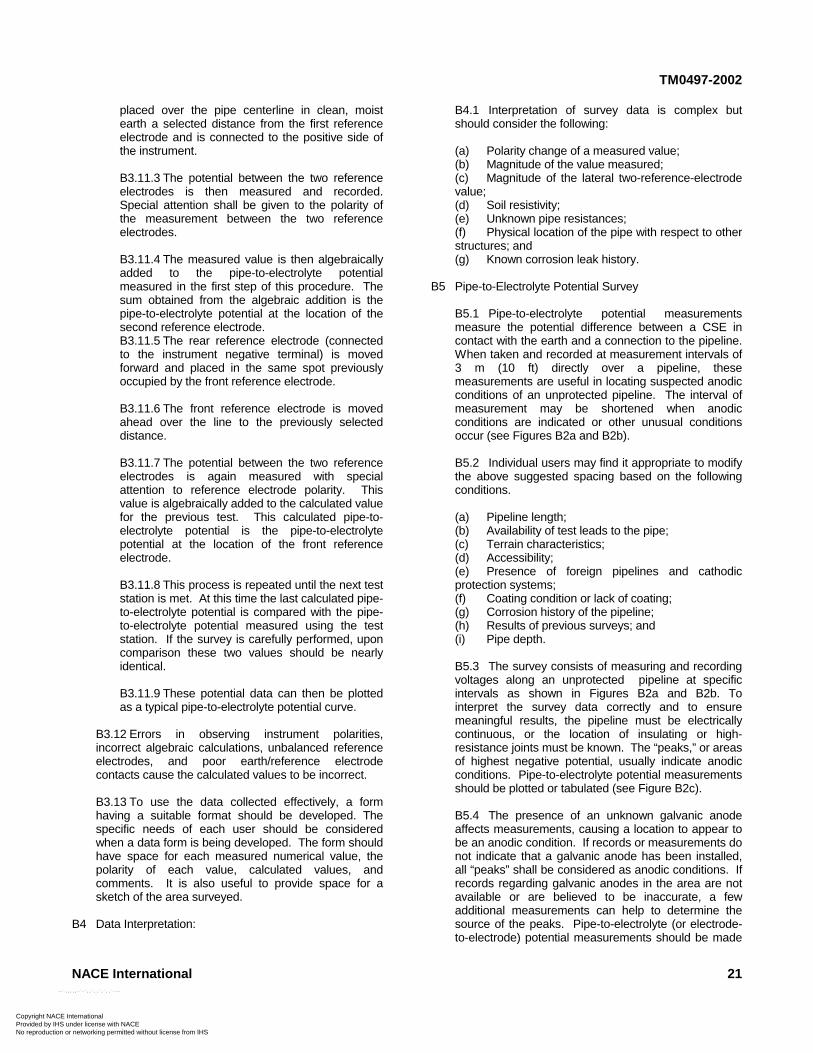
TM0497-2002
CPN
placed over the pipe centerline in clean, moistearth a selected distance from the first referenceelectrode and is connected to the positive side ofthe instrument.
B3.11.3 The potential between the two referenceelectrodes is then measured and recorded.Special attention shall be given to the polarity ofthe measurement between the two referenceelectrodes.
B3.11.4 The measured value is then algebraicallyadded to the pipe-to-electrolyte potentialmeasured in the first step of this procedure. Thesum obtained from the algebraic addition is thepipe-to-electrolyte potential at the location of thesecond reference electrode.B3.11.5 The rear reference electrode (connectedto the instrument negative terminal) is movedforward and placed in the same spot previouslyoccupied by the front reference electrode.
B3.11.6 The front reference electrode is movedahead over the line to the previously selecteddistance.
B3.11.7 The potential between the two referenceelectrodes is again measured with specialattention to reference electrode polarity. Thisvalue is algebraically added to the calculated valuefor the previous test. This calculated pipe-to-electrolyte potential is the pipe-to-electrolytepotential at the location of the front referenceelectrode.
B3.11.8 This process is repeated until the next teststation is met. At this time the last calculated pipe-to-electrolyte potential is compared with the pipe-to-electrolyte potential measured using the teststation. If the survey is carefully performed, uponcomparison these two values should be nearlyidentical.
B3.11.9 These potential data can then be plottedas a typical pipe-to-electrolyte potential curve.
B3.12 Errors in observing instrument polarities,incorrect algebraic calculations, unbalanced referenceelectrodes, and poor earth/reference electrodecontacts cause the calculated values to be incorrect.
B3.13 To use the data collected effectively, a formhaving a suitable format should be developed. Thespecific needs of each user should be consideredwhen a data form is being developed. The form shouldhave space for each measured numerical value, thepolarity of each value, calculated values, andcomments. It is also useful to provide space for asketch of the area surveyed.
B4 Data Interpretation:
opyright NACE International rovided by IHS under license with NACE
Not o reproduction or networking permitted without license from IHS
B4.1 Interpretation of survey data is complex butshould consider the following:
(a) Polarity change of a measured value;(b) Magnitude of the value measured;(c) Magnitude of the lateral two-reference-electrodevalue;(d) Soil resistivity;(e) Unknown pipe resistances;(f) Physical location of the pipe with respect to otherstructures; and(g) Known corrosion leak history.
B5 Pipe-to-Electrolyte Potential Survey
B5.1 Pipe-to-electrolyte potential measurementsmeasure the potential difference between a CSE incontact with the earth and a connection to the pipeline.When taken and recorded at measurement intervals of3 m (10 ft) directly over a pipeline, thesemeasurements are useful in locating suspected anodicconditions of an unprotected pipeline. The interval ofmeasurement may be shortened when anodicconditions are indicated or other unusual conditionsoccur (see Figures B2a and B2b).
B5.2 Individual users may find it appropriate to modifythe above suggested spacing based on the followingconditions.
(a) Pipeline length;(b) Availability of test leads to the pipe;(c) Terrain characteristics;(d) Accessibility;(e) Presence of foreign pipelines and cathodicprotection systems;(f) Coating condition or lack of coating;(g) Corrosion history of the pipeline;(h) Results of previous surveys; and(i) Pipe depth.
B5.3 The survey consists of measuring and recordingvoltages along an unprotected pipeline at specificintervals as shown in Figures B2a and B2b. Tointerpret the survey data correctly and to ensuremeaningful results, the pipeline must be electricallycontinuous, or the location of insulating or high-resistance joints must be known. The “peaks,” or areasof highest negative potential, usually indicate anodicconditions. Pipe-to-electrolyte potential measurementsshould be plotted or tabulated (see Figure B2c).
B5.4 The presence of an unknown galvanic anodeaffects measurements, causing a location to appear tobe an anodic condition. If records or measurements donot indicate that a galvanic anode has been installed,all “peaks” shall be considered as anodic conditions. Ifrecords regarding galvanic anodes in the area are notavailable or are believed to be inaccurate, a fewadditional measurements can help to determine thesource of the peaks. Pipe-to-electrolyte (or electrode-to-electrode) potential measurements should be made
NACE International 21--`,,,,,-`-`,,`,,`,`,,`---
for Resale
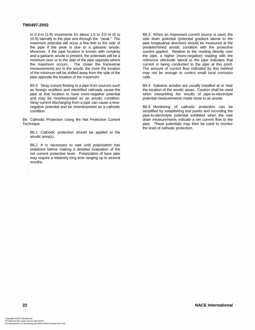
CPN
TM0497-2002
o re
in 0.3-m (1-ft) increments for about 1.5 to 3.0 m (5 to10 ft) laterally to the pipe and through the “peak.” Themaximum potential will occur a few feet to the side ofthe pipe if the peak is due to a galvanic anode.Moreover, if the pipe location is known with certaintyand a galvanic anode is present, the potentials will be aminimum over or to the side of the pipe opposite wherethe maximum occurs. The closer the transversemeasurements are to the anode, the more the locationof the minimum will be shifted away from the side of thepipe opposite the location of the maximum.
B5.5 Stray current flowing to a pipe from sources suchas foreign rectifiers and electrified railroads cause thepipe at that location to have more-negative potentialand may be misinterpreted as an anodic condition.Stray current discharging from a pipe can cause a less-negative potential and be misinterpreted as a cathodiccondition.
B6 Cathodic Protection Using the Net Protective CurrentTechnique
B6.1 Cathodic protection should be applied to theanodic area(s).
B6.2 It is necessary to wait until polarization hasstabilized before making a detailed evaluation of thenet current protective level. Polarization of bare pipemay require a relatively long time ranging up to severalmonths.
--`,,,,,-`-`,,`,
Not foproduction or networking permitted without license from IHS
,`,`,,`---
B6.3 When an impressed current source is used, theside drain potential (potential gradient lateral to thepipe longitudinal direction) should be measured at thepredetermined anodic condition with the protectivecurrent applied. Relative to the reading directly overthe pipe, a higher (more-negative) reading with thereference electrode lateral to the pipe indicates thatcurrent is being conducted to the pipe at this point.The amount of current flow indicated by this methodmay not be enough to control small local corrosioncells.
B6.4 Galvanic anodes are usually installed at or nearthe location of the anodic areas. Caution shall be usedwhen interpreting the results of pipe-to-electrolytepotential measurements made close to an anode.
B6.5 Monitoring of cathodic protection can besimplified by establishing test points and recording thepipe-to-electrolyte potential exhibited when the sidedrain measurements indicate a net current flow to thepipe. These potentials may then be used to monitorthe level of cathodic protection.
22 NACE International
opyright NACE International rovided by IHS under license with NACE
r Resale
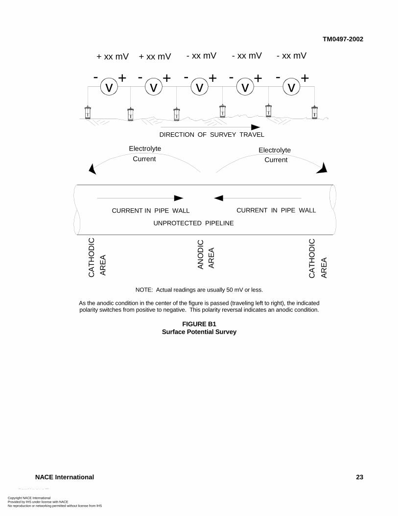
CPN
TM0497-2002
NACE International 23
v- - - - -++ + + +
+ xx mV - xx mV- xx mV- xx mV+ xx mV
CURRENT IN PIPE WALL CURRENT IN PIPE WALL
DIRECTION OF SURVEY TRAVEL
CA
TH
OD
IC
AR
EA
AN
OD
ICA
RE
A
CA
TH
OD
IC
AR
EA
Electrolyte
CurrentElectrolyte
Current
UNPROTECTED PIPELINE
v vvv
NOTE: Actual readings are usually 50 mV or less.
As the anodic condition in the center of the figure is passed (traveling left to right), the indicatedpolarity switches from positive to negative. This polarity reversal indicates an anodic condition.
FIGURE B1Surface Potential Survey
opyright NACE International
--`,,,,,-`-`,,`,,`,`,,`---
rovided by IHS under license with NACENot for Resaleo reproduction or networking permitted without license from IHS
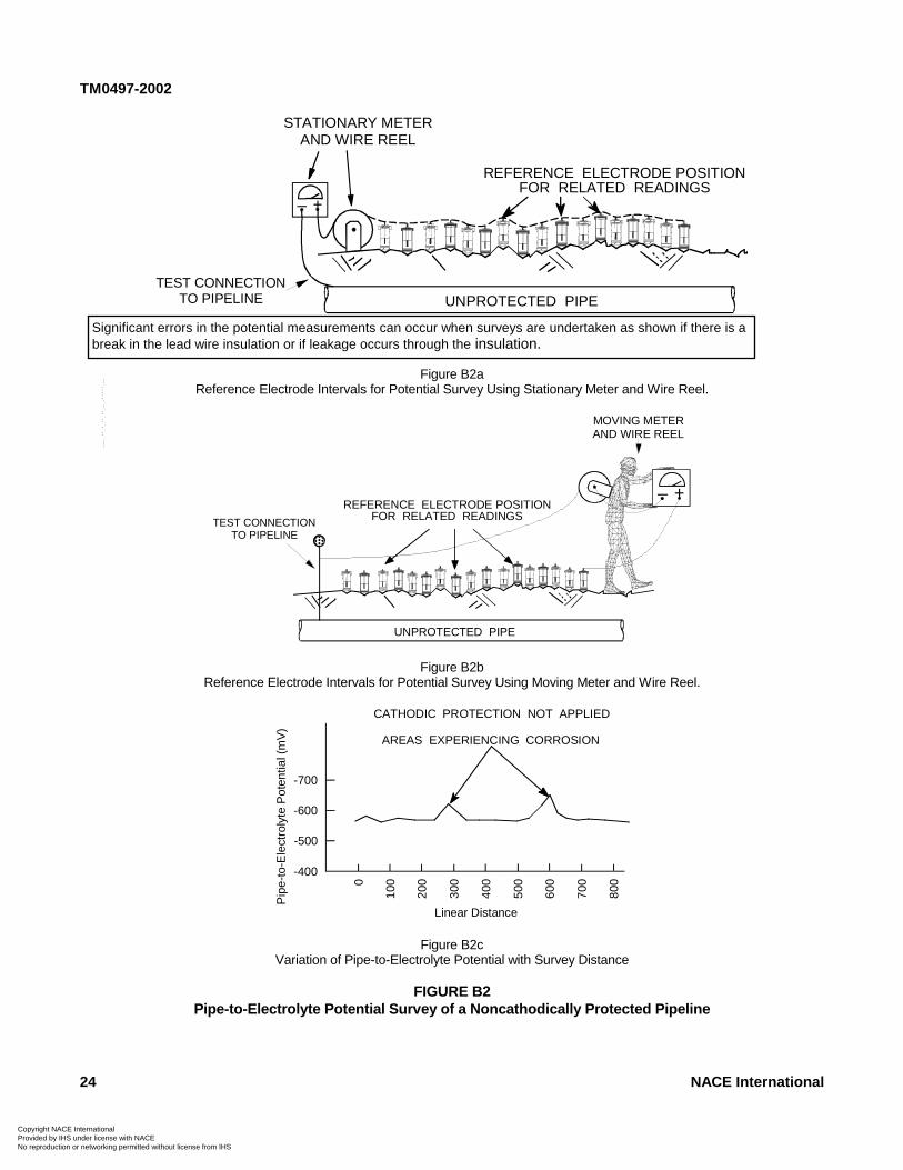
TM0497-2002
24 NACE International
STATIONARY METERAND WIRE REEL
UNPROTECTED PIPE
+_
REFERENCE ELECTRODE POSITIONFOR RELATED READINGS
TEST CONNECTIONTO PIPELINE
NOTE: Cathodic protection not applied.
Figure B2aReference Electrode Intervals for Potential Survey Using Stationary Meter and Wire Reel.
UNPROTECTED PIPE
REFERENCE ELECTRODE POSITIONFOR RELATED READINGSTEST CONNECTION
TO PIPELINE
MOVING METERAND WIRE REEL
+_
Figure B2bReference Electrode Intervals for Potential Survey Using Moving Meter and Wire Reel.
0
100
200
300
400
500
600
700
800
-400
-500
-600
Pip
e-to
-Ele
ctro
lyte
Pot
entia
l(m
V)
AREAS EXPERIENCING CORROSION
-700
CATHODIC PROTECTION NOT APPLIED
Linear Distance
Figure B2cVariation of Pipe-to-Electrolyte Potential with Survey Distance
FIGURE B2Pipe-to-Electrolyte Potential Survey of a Noncathodically Protected Pipeline
Significant errors in the potential measurements can occur when surveys are undertaken as shown if there is abreak in the lead wire insulation or if leakage occurs through the insulation.
Copyright NACE International Provided by IHS under license with NACE
--`,,,,,-`-`,,`,,`,`,,`---
Not for ResaleNo reproduction or networking permitted without license from IHS
CopyProvidNo re
TM0497-2002
________________________________________________________________________
Appendix C: Using Coupons to Determine Adequacy of Cathodic Protection
ri
p
C1 Coupons have been used judiciously, particularly whenaccompanied by other engineering tools and data, toevaluate whether cathodic protection at a test site complieswith a given criterion. See NACE Publication 352014 formore information on coupon use. The following testprocedures are suggested as guides.
C2 Cathodic Protection Coupon Test Method 1—forNegative 850 mV Polarized Pipe-to-Electrolyte Potential ofSteel and Cast Iron Piping
C2.1 Scope
This method uses a cathodic protection coupon toassess the adequacy of cathodic protection on a steelor cast iron pipeline according to the criterion stated inNACE Standard RP0169,1 Paragraph 6.2.2.1.2:
A negative polarized potential of at least 850 mVrelative to a saturated copper/copper sulfatereference electrode (CSE).
C2.2 General
C2.2.1 This method uses a coupon to assess theadequacy of cathodic protection applied to aselected test site. A cathodic protection coupon isa metal sample representing the pipeline at thetest site and used for cathodic protection testing.The coupon should be:
(a) Nominally of the same metal and surfacecondition as the pipe;(b) Small to avoid excessive current drain onthe cathodic protection system;(c) Placed at pipe depth in the same backfill asthe pipe;(d) Prepared with all mill scale and foreignmaterials removed from the surface; and(e) Placed at a known location of an ineffectivecoating when the line is coated.
C2.2.2 A coupon has an insulated test leadbrought above ground and, during normaloperations, connected to a pipeline test lead. Thecoupon receives cathodic protection current andrepresents the pipeline at the test site. For testingpurposes, this connection is opened, and thepolarized potential of the coupon is measured.The time the connection is open to measure thecoupon’s “off” potential should be minimized toavoid significant depolarization of the coupon. The“off” period is typically less than 3 seconds. Whenpossible, coupon current direction and magnitudeshould be verified, using a current clip gauge orresistor permanently placed in series with thecoupon lead. Measurements showing discharge
--`,,,,,-`-`,,`,,`,`,,`---
ght NACE International ed by IHS under license with NACE
Not foroduction or networking permitted without license from IHS
of current from the coupon should be reason toquestion the validity of using a coupon at the testsite.
C2.2.3 The significance of voltage drops due tocurrents from other sources may not be a problemwhen a coupon is used to represent the pipeline.The coupon’s small size may reduce the effect ofthese voltage drops. The magnitude of thesevoltage drops can be quantified by interruptingcathodic protection current sources while thecoupon is disconnected and noting whether thereis a shift in the coupon-to-electrolyte potential.
C2.3 Comparison with Other Methods
C2.3.1 Advantages
(a) Can provide a polarized coupon-to-electrolyte potential, free of voltage drop, with aminimum of specialized equipment, personnel,and vehicles; and(b) Can provide a more comprehensiveevaluation of the polarization at the test site thanconventional pipe-to-electrolyte potentialmeasurements that may be influenced by thelocation, size, and number of coating holidayswhen the pipeline is coated.
C2.3.2 Disadvantage—Can have high initial coststo install coupons, especially for existing pipelines.
C2.4 Basic Test Equipment
C2.4.1 Voltmeter with adequate input impedance.Commonly used digital instruments have anominal impedance of 10 megaohms. An analoginstrument with an internal resistance of 100,000ohms per volt may be adequate in certaincircumstances in which the circuit resistance islow. A potentiometer circuit may be necessary inother instances.
C2.4.2 Two color-coded meter leads with clips forconnection to the coupon and reference electrode.
C2.4.3 Reference electrode
C2.4.3.1 CSE
C2.4.3.2 Other standard referenceelectrodes may be substituted for the CSE.These reference electrodes are described inAppendix A, Paragraph A2.
C2.5 Procedure
NACE International 25
r Resale
CopyrigProvideNo repr
TM0497-2002
ht NACE Ind by IHS uoduction or
C2.5.1 Before the test, verify that:
(a) Cathodic protection equipment has beeninstalled and is operating properly; and(b) Coupon is in place and connected to apipeline test lead.
Time should be allowed for the pipeline andcoupon potentials to reach polarized values.
C2.5.2 Determine the location of the site to betested. Selection of a site may be based on:
(a) Location accessible for future monitoring;(b) Other protection systems, structures, andanodes that may influence the pipe-to-electrolyteand coupon-to-electrolyte potentials;(c) Electrical midpoints between protectiondevices;(d) Known location of an ineffective coatingwhen the line is coated; and(e) Location of a known or suspected corrosiveenvironment.
C2.5.3 Make electrical contact between thereference electrode and the electrolyte at the testsite as close to the coupon as is practicable.
C2.5.4 Connect the voltmeter to the coupon testlead and reference electrode as described inParagraph 5.6.
C2.5.5 Measure and record the pipeline andcoupon “on” potentials.
C2.5.6 Momentarily disconnect the coupon testlead from the pipeline test lead and immediatelymeasure and record the coupon-to-electrolyte “off”potential and its polarity with respect to thereference electrode. This should be performedquickly to avoid depolarization of the coupon.
C2.5.7 Reconnect the coupon test lead to thepipeline test lead for normal operations.
C2.6 Evaluation of Data
Cathodic protection may be judged adequate at thetest site if the polarized coupon-to-electrolyte potentialis negative 850 mV, or more negative, with respect to aCSE. The polarized potential of the coupon dependson the coupon surface condition, the soil in which thecoupon is placed, its level of polarization, and its timepolarized. Therefore, the polarized potential of thecoupon may not be the same as that of the pipe andmay not accurately reflect the polarization on the pipeat the coupon location. It must also be understood thatthe polarization measured on the pipeline is a“resultant” of the variations of polarization on the pipeat the test site. The causes of these variations includethe pipe surface condition, soil strata variations, oxygendifferentials, and length of time the pipe has been
ternational nder license with NACE
Not fo networking permitted without license from IHS
polarized. Making precise comparisons may not bepossible.
C2.7 Monitoring
When the polarized coupon-to-electrolyte potential hasbeen determined to equal or to exceed a negative 850mV, the pipeline “on” potential may be used formonitoring unless significant environmental, structural,coating integrity, or cathodic protection systemparameters have changed.
C3 Cathodic Protection Coupon Test Method 2—for 100mV Cathodic Polarization of Steel, Cast Iron, Aluminum,and Copper Piping
C3.1 Scope
This method uses cathodic protection couponpolarization decay to assess the adequacy of cathodicprotection on a steel, cast iron, aluminum, or copperpipeline according to the criteria stated in NACEStandard RP0169,1 Paragraphs 6.2.2.1.3, 6.2.3.1, or6.2.4.1 (depending on the pipe metal). The paragraphbelow states Paragraph 6.2.2.1.3:
The following criterion shall apply: A minimum of100 mV of cathodic polarization between thestructure surface and a stable reference electrodecontacting the electrolyte. The formation or decayof polarization can be measured to satisfy thiscriterion.
C3.2 General
Ferrous, aluminum, and copper pipelines may beadequately cathodically protected when applyingcathodic protection causes a polarization change of100 mV or more with respect to a reference potential.
C3.2.1 This method uses a coupon to assess theadequacy of cathodic protection applied at a testsite. A cathodic protection coupon is a metalsample representing the pipeline at the test siteand used for cathodic protection testing. Thecoupon should be:
(a) Nominally of the same metal and surfacecondition as the pipe;(b) Small to avoid excessive current drain onthe cathodic protection system;(c) Placed at pipe depth in the same backfill asthe pipe;(d) Prepared with all mill scale and foreignmaterials removed from the surface; and(e) Placed at a known location of an ineffectivecoating when the line is coated.
C3.2.2 The significance of voltage drops due tocurrents from other sources may be accounted forwhen a coupon is used to represent the pipeline.The magnitude of these voltage drops can be
--`,,,,,-`-`,,`,,`,`,,`---
26 NACE International
r Resale
CoProNo
TM0497-2002
p
quantified by interrupting cathodic protectionsources while the coupon is disconnected andnoting whether there is a shift in the coupon-to-electrolyte potential.
C3.2.3 A coupon has an insulated test leadbrought above ground and, during normaloperations, connected to a pipeline test lead. Thecoupon receives cathodic protection current andrepresents the pipeline at the test site. For testingpurposes, this connection is opened, and thepolarized “off” potential of the coupon is measured.The time the connection is open to measure thecoupon’s “off” potential should be minimized toavoid significant depolarization of the coupon. The“off” period is typically less than 3 seconds. Thecoupon is then allowed to depolarize. Whenpossible, coupon current direction and magnitudeshould be verified, using a current clip gauge orresistor permanently placed in series with thecoupon lead. Measurements showing dischargeof current from the coupon should be reason toquestion the validity of using a coupon at the testsite.
C3.3 Comparison with Other Methods
C3.3.1 Advantages
(a) Can measure coupon-to-electrolyte polari-zation decay with a minimum of specializedequipment, personnel, and vehicles;(b) Can provide an indication of the amount ofpolarization present at the test site withoutinterrupting the cathodic protection currentsupplied to the pipeline;(c) Can provide a better indication of cathodicprotection levels due to eliminating the effects of“long-line” current flow when the pipeline “off”potentials are measured.
C3.3.2 Disadvantage—Can have high initial coststo install a coupon, especially for existingpipelines.
C3.4 Basic Test Equipment
C3.4.1 Voltmeter with adequate input impedance.Commonly used digital instruments have anominal impedance of 10 megaohms. An analoginstrument with an internal resistance of 100,000ohms per volt may be adequate in certaincircumstances where the circuit resistance is low.A potentiometer circuit may be necessary in otherinstances.
C3.4.2 Two color-coded meter leads with clips forconnection to the coupon and reference electrode.
C3.4.3 Reference electrode
C3.4.3.1 CSE.
yright NACE International vided by IHS under license with NACE
Noreproduction or networking permitted without license from IHS
C3.4.3.2 Other standard referenceelectrodes may be substituted for the CSE.These reference electrodes are described inAppendix A, Paragraph A2.
C3.5 Procedure
C3.5.1 Before the test, verify that:
(a) Cathodic protection equipment is installed(b) and operating properly; and(c) Coupon is in place and connected to apipeline test lead.
Time shall be allowed for the pipeline and couponpotentials to reach polarized values.
C3.5.2 Determine the location of the site to betested. Selection of a site may be based on:
(a) Location accessible for future monitoring;(b) Other protection systems, structures, andanodes that may influence the pipe-to-electrolyteand coupon-to-electrolyte potentials;(c) Electrical midpoints between protectiondevices;(d) Known location of an ineffective coatingwhen the line is coated; and(e) Location of a known or suspected corrosiveenvironment.
C3.5.3 Make electrical contact between thereference electrode and the electrolyte at the testsite as close to the coupon as is practicable.
C3.5.3.1 Identify the location of theelectrode to allow it to be returned to thesame location for subsequent tests.
C3.5.4 Connect the voltmeter to the coupon testlead and reference electrode as described inParagraph 5.6.
C3.5.5 Measure and record the pipeline andcoupon “on” potentials.
C3.5.6 Disconnect the coupon test lead from thepipeline test lead and immediately measure thecoupon-to-electrolyte potential.
C3.5.6.1 The coupon-to-electrolytepotential becomes the “base line value” fromwhich polarization decay is measured.
C3.5.7 Record the coupon-to-electrolyte “off”potential and its polarity with respect to thereference electrode.
C3.5.8 Leave the coupon test lead disconnectedto allow the coupon to depolarize.
NACE International 27--`,,,,,-`-`,,`,,`,`,,`---
t for Resale
CPN
TM0497-2002
opyrighrovidedo repro
C3.5.9 Measure and record the coupon-to-electrolyte potential periodically. The differencebetween it and the “off” potential is the amount ofpolarization decay. Continue to measure andrecord the coupon-to-electrolyte potential until iteither:
(a) Has become at least 100 mV less negativethan the “off” potential; or(b) Has reached a stable depolarized level.
C3.5.10 Reconnect the coupon test lead to thepipeline test lead for normal operations.
C3.6 Evaluation of Data
Cathodic protection may be judged adequate at thetest site when 100 mV or more of polarization decay ismeasured with respect to a standard reference
28
t NACE International by IHS under license with NACE
Not forduction or networking permitted without license from IHS
electrode. The depolarized potential of the coupondepends on the coupon surface condition, the soil inwhich the coupon is placed, its level of polarization,and its time polarized. Therefore, the depolarizedpotential of the coupon may not be the same as that ofthe pipe and may not accurately reflect the polarizationon the pipe at the coupon location. It must also beunderstood that the polarization measured on thepipeline is a “resultant” of the variations of polarizationon the pipe at the test site. These variations arecaused by the pipe surface condition, soil stratavariations, oxygen differentials, and time the pipe hasbeen polarized. Making precise comparisons may notbe possible.
C3.7 Monitoring
When at least 100 mV or more of polarization decayhas been measured, the pipeline “on” potential at thetest site may be used for monitoring unless significantenvironmental, structural, coating integrity, or cathodicprotection system parameters have changed. -
-`,,,,,-`-`,,`,,`,`,,`---
NACE International
Resale