nace_2005
TRANSCRIPT
COLLECTING AND USING BOILER TUBE DEPOSIT LOADING DATA
Steven C. Heifner and Eric P. ThurstonDavid N. French Metallurgists1345 Old Preston Highway N.
Louisville, KY 40229
Paper #05442 (with updates)
ABSTRACT
Guidance on selecting boiler tube samples for deposit loading testing, information onhow the deposit loading tests are performed, and what actions need to be taken based on the resultsobtained are offered. Deposits inside boiler tubes impact the operation of a boiler by creatinginsulating barriers that prevent the efficient transfer of heat from flame to steam, thereby increasingoperating costs. Decisions to remove excessive deposits must occur to restore operational andeconomic efficiency. The influence that different boiler designs and operating conditions have ondeposit loading test site selection is presented. Published chemical cleaning decision thresholds forhigh pressure utility boilers employed since 1971 are reviewed and reconsidered. Recommendedactions in collecting and using boiler tube deposit loading data to make chemical cleaning decisionsfor power generation utility boilers are offered.
Keywords: deposit loading, deposit weight density, boiler tube deposits, deposit removal, boilerchemical cleaning’boiler tubes, density deposits, steam generators.
INTRODUCTION
In 1971, after four years of development, Atwood and Hale1 presented “A Method for Determining the Need for Chemical Cleaning of High–Pressure Boilers.”In 1983, this method wasformalized within ASTM Standard D34832. Two standard test methods: A) Mechanical Removaland B) Solvent Removal are included in ASTM Standard D3483. In 1999, ASTM Standard D3483was reaffirmed without alteration. Also in 1999, NACE Standard TM0199-993 was issueddescribing a glass-bead-blasting (GBB) removal technique. The GBB technique was developed toaccelerate removal of deposits, especially tightly adherent deposits, in a consistent and controlledmanner.
Boiler tube deposit loadings are routinely used to make boiler chemical cleaningdecisions in the power generation industry. Deposits interfere with the efficient operation of a
boiler, and can lead to failures due to overheating and corrosion. Making the right cleaning decisionrequires obtaining meaningful deposit loading measurements and interpreting them correctly. Theselection of test sites and the analysis test method employed greatly influences the loadingmeasurements obtained. Deposit loading measurements are also referred to as a deposit weightdensity (DWD), or mass loading, measurements. This paper is intended to help power generationpersonnel interpret deposit measurements and make boiler chemical cleaning decisions. Otherdeposit information analysis techniques are discussed as they relate or interact with deposit loadingmeasurements.
SELECTING TUBE SAMPLES FOR DEPOSIT LOADING TESTING
A typical power generation boiler contains hundreds of miles of tubing. The purposeof this tubing and the coolant within this tubing is to create a device to generate steam at a definedtemperature and pressure from the combustion of a suitable fuel. Steam-generating units aredesigned to balance the heat input from fuel combustion with the formation and superheating ofsteam. Within the furnace, flame temperatures may approach 3000 °F [1650 °C], which throughfurnace wall heat absorption and steam generation, is reduced to 1700 °F to 2000 °F [925 °C to 1100°C] in flue gases at the furnace exit. A temperature gradient between the tube wall and the fluidwithin the tube provides the driving force for heat transfer at any given point. Coolant fluid statesinclude: sub-cooled water, boiling water, saturated steam, and superheated steam. The operation of afurnace is a balance between the formation of steam and the flow of thermal energy from thecombustion of a fuel. When this balance is maintained, the metal temperature of the boiler tube isappropriate for the material, however when the balance is upset, tube metal temperature can rise andfailures will occur.
When a layer of deposits from the boiling water forms inside a furnace tube, heattransfer is impeded, and the net effect is to raise the temperature of that tube. Deposits lead toincreased tube-metal temperatures because the thermal conductivity of the deposit is less than thesteel. Higher tube temperatures promote under-deposit corrosion and hydrogen damage. As depositsincrease, furnace tubes can also fail by a creep or stress-rupture mechanism. Deposits may formanywhere; however, some locations are more susceptible than others as described later. Sincedeposits are hidden, identifying the dirtiest locations requires an understanding of deposits and theirdeposition patterns.
The deposits that form inside a tube come from three sources: 1) oxidation of tubebase metal, 2) transport of corrosion products from other portions of boiler, and 3) impurities in thefluid coolant. When steel is exposed to water, it forms a protective oxide layer. This layer consistsof a tightly adherent outer layer (towards the OD) and a porous inner layer (towards the ID).Atwood and Hale identified the outer layer as “hard” and the inner layer as “soft.” The “hard” outer layer forms rapidly after fresh surface exposures, and stabilizes in thickness in a few days (~2 to 3days) after exposure. The hard “outer” layer thickness that forms is dependent on the tube metal temperature, and is usually around 3 mils (0.003") [0.07 mm] in thickness in a typical high-pressurepower boiler. The “hard” outer layer is more of a scale formation associated with tube metaloxidation rather than a transported deposit; however the distinction between “hard” and “soft” oxide layers is indeterminable during removal of a loading for measurement. Both the “hard” and “soft” layers consist primarily of magnetite (Fe3O4) and the mechanical, solvent, and glass-bead removalmethods available make no fixed distinction regarding the deposit layer that is removed andmeasured.
Iron oxide, other oxides and impurities are transported and deposited within a boilertube through the feedwater to form a “soft” deposit layer on top of the “hard” scale layer. The transportation of corrosion products from other locations, especially from the pre-boiler system,forms a porous layer of low bulk density. “Soft” deposits play the primary role in corrosion-relatedfailures such as: hydrogen damage, caustic gouging, and acid phosphate corrosion. Typical pre-boiler corrosion products include: copper, zinc, and nickel. Phosphate, calcium magnesiumcarbonate, and silica enter from improperly treated water used as the coolant media. These pre-boiler corrosion products mix with iron oxide, changing “soft” deposits into adherent insulating surface deposits. The boundary between the “hard” layer and the “surface” layer can remain “soft” and unstable, leading to potential deposit exfoliation. Separation of “soft” deposits during sample removal impacts loading measurements.
Atwood and Hale classified deposit characteristics; however, such characterizationswere not incorporated into ASTM D3483 or NACE Standard TM0199-99 test methods, norembraced by the power generation industry. Obtaining a quantitative deposit loading measurementversus a qualitative deposit morphology judgment was accepted as defining cleanliness in a boiler.Boiler manufacturers, water treatment suppliers, laboratories, consultants and utility operatorsdefined and promoted cleanliness thresholds based upon their differing deposit loading measurementexperiences. Test method measurement differences influenced cleanliness and chemical cleaningrecommendation thresholds that were established and are currently in use as presented in Figure 1.
Deposit loading measurement requires removal of a tube section. Removing a tubesample incurs a cost; more tube samples entail more costs. It would be preferred to have a non-destructive deposit loading inspection method for use. Ultrasonic (UT) and eddy current (EC)deposit loading measurements have been attempted, however surface cleaning on the OD (outsidediameter) surface is required to attach the probe to perform an ID (inside diameter) deposit loadingmeasurement. In addition, the reflection of the UT beam at the deposit to tube metal interface isextremely difficult to resolve. Video probes or borescopes may be used to examine the ID depositsurface condition; however, tube penetrations must still be made and repaired to insert the visualinspection device and no depth or density information is collected. Thermocouples have been usedto measure temperature changes associated with deposit loadings; however, such thermocouplesoften fail and therefore offer no cost savings. Infrared thermal analysis may identify hot areasindicating the possibility of deposits, but not the presence of deposits. Ash temperature can masktube metal temperature therefore infrared thermal analysis does not directly measure heat flux, justheat. Removing a tube sample has become and remains the preferred and accepted method forperforming deposit loadings within power generation utility boilers.
Tube samples should be removed from the highest heat flux regions of the furnace.Heat flux is the rate of energy transfer through a given surface. In a boiler, heat flow through wallsinfluences the thermodynamic balance provided by the fluid within the tubes. Tube-metaltemperature increases are a function of the heat flux. Therefore, the insulating effect of the steam-side scale will increase tube-metal temperatures the most in high heat flux regions. In addition,furnace elevation impacts heat flux, decreasing with distance from the combustion zone. Tube-metaltemperature will be highest, and therefore corrosion rates will be fastest in high heat flux areas.Highest heat flux, highest heat transfer, and highest heat absorption are equivalent terms. The metaltemperature varies around the perimeter of the tube. The highest metal temperature is typically alongthe centerline of the fireside of the tube, midway between the membranes, however with tangentiallyfired units, the thickest deposit is approximately at 1 o’clock position facing toward the flame from
the corner burner. Because the metal temperature varies around the perimeter, the amount of depositwill also vary around the perimeter. The cold side or casing side of the waterwall tube will have theleast deposit. Therefore, a single deposit loading measurement along the hot side of the tube canprovide a meaningful characterization of deposit loading at a given sample location. However, onegiven sample location does not provide a meaningful characterization of deposit loading throughoutthe sampled utility boiler.
If a boiler tube fails, there is an opportunity to remove a deposit-loading sample atlow additional cost during the failure repair. Higher operating temperatures often drive failures, andcan be indicative of deposit build-up occurring. Historical problem areas for a given unit, or similarunits, provide extremely useful insight on what locations should be sampled, at failures andperiodically, to understand how much and what deposits that are forming. Boiler manufacturerstypically recommend locations to be sampled for their units in order for the boiler operator to collectthe most useful and predicative deposit loading data. High temperature exposure exacerbatescorrosion and/or creep activity. The burner level, and just above, experiences the highesttemperature exposure within a utility boiler. This high temperature exposure does not occur at asingle spot or tube, but as a band of exposure impacting many tubes. The weakest link will fail first,however there can be many other weak links also about to fail that be subsequently and soon fail.Using a single data point to characterize the deposit loading throughout a utility boiler is a riskymeasurement and characterization. At a minimum two data points should be measured, howeverpreferably four points should be used, to confirm the worse case deposit loading is beingcharacterized. More data points will confirm that a correct chemical cleaning decision is actuallybeing made.
Besides nearness to a failure, or other historical location insight, the firesideappearance of a tube can suggest waterside problem sites with excessive deposits loadings thatshould be sampled and characterized. Tube misalignments and dislocations cause flow disruptionsthat increase the likelihood of cooling complications and deposit build-up. Flame impingementcause heating complications elevating tube metal temperatures. Fuel changes impact heat generationand absorption. Some fuels generate more ash, which insulates the tube, shifting heat absorptionzones within a boiler. Sootblowers remove ash, further influencing, and hopefully restoring,expected heat absorption.
Typically, two-foot specimens are taken above the upper burner for deposit loadingmeasurement. ASTM D8874 recommends removal of three-foot samples. Removal costs for longerspecimens are nearly the same as for shorter specimens, but subsequent specimen handling is moredifficult and costly. Possible contamination or disturbance of the deposit during sample removalsuggests longer specimens. Straight sections are typically removed for deposit loading evaluation tosimplify removal and replacement. Window samples, especially from arch tubes, are possible, butcontamination and disturbance potential are substantially increased. Cutting wheels, not cuttingtorches, should be used to remove deposit loading specimens; saws for cutting is preferred but neverdeployed within the boiler. Cuts penetrating the tube ID should be a minimum of 6 in [15 cm] fromthe area of concern or interest. It is extremely helpful to add identification details to the tube prior tospecimen removal. Identification should include: date of removal, tube number, location includingelevation, type of material, fluid flow direction, hot side, and cold side. Photo documentation prior toremoval, and upon receipt at the test lab, is also recommended. Sometimes overlapping sections areremoved during sequential shutdowns in order to perform subsequent deposition comparisons.Specimen tube ends should be sealed (often using duct tape or plastic caps) immediately uponremoval to prevent ID contamination.
HOW THE DEPOSIT LOADING TESTS ARE PERFORMED
The mechanical removal, the solvent removal, and the glass-bead-blasting depositloading test methods in use today are outlined in Figures 2, 3, and 4, respectively. The mechanicaland solvent removal test method outlines are based on ASTM Standard D34832, and the glass-bead-blasting method outline is based on NACE Standard TM0199-993.
During the 1990s, NACE sponsored a round-robin deposit loading test program.Three (3) round-robin participants employed the mechanical test method, five (5) participants thesolvent test method, and eight (8) participants the glass-bead-blasting (GBB) test method, plus three(3) additional participants employed non-standardized test methodologies. NACE InternationalWork Group T-7H-6f on Deposit Weight Density Methodology issued a summary report5 on thiswork in July of 2000. The number of round-robin participants, and the test results collected, wasinsufficient to demonstrate statistical accuracy and reproducibility of any particular test method.This round-robin testing minimized test material variability, from two (2) lots of test material, in aneffort to characterize and understand test technique variability. In general terms, employing thesolvent removal test method was confirmed to give highest deposit loading measurements. Figure 1of ASTM D 3483 specifically identifies that the chemical removal method will remove more depositthan the mechanical removal method until a significant (>10 g/ft2) [>10mg/cm2] deposit layerdevelops. The mechanical removal and glass-bead-blasting (GBB) test methods were judged byWork Group T-7H-6f to deliver similar deposit loading measurements. It is clear that aninexperienced tester can seriously influence deposit loading test results being collected. Testersmust maintain technique consistency as they employ deposit loading test methods in their respectivelaboratories. The establishment of cleanliness thresholds used to determine the need for boilercleaning based upon deposit loadings should recognize and allow for such measurement variations.Making a chemical cleaning decision based upon a single deposit loading data point is an extremelyrisky and potentially costly because of deposit loading measurement variations that can and dooccur. Trend data using a single deposit loading test method to validate the collection method isrequired to obtain meaningful results that can be acted upon.
The mechanical removal method, the solvent removal method, and the glass beadblasting (GBB) removal method are all valid test methods that can be employed. IncorporatingNACE Standard TM0199-99 glass-bead-blasting (GBB) test method within ASTM D 3483 wasdiscussed by round-robin participants, but was never actively pursued.
WHAT ACTIONS NEED TO BE TAKEN BASED ON THE RESULTS OBTAINED
The commonly accepted method for evaluating the need for chemical cleaning is toevaluate waterside cleanliness by removing and testing tube samples. Additional testing such aschemical composition and morphology of the deposit can be collected in parallel with the depositloading sample.
EPRI8 recommends the cleaning of water-touched tubes:
Whenever deposit loading exceeds a given threshold value. After any water chemistry upset resulting in a low or high pH level.

After a long period of severe condenser tube leakage (>6 months). After discovery of an under-deposit corrosion tube failure. After overheating failures with an indication of deposit buildup. After overheating failure due to blockage caused by deposit exfoliation. When system pressure drops are increasing. After previous unsuccessful/incomplete chemical cleans. At changes of coolant water chemistry treatments. At changes in fuels that impact heat flux in the boiler. After extended boiler lay-ups. Whenever major waterwall replacement event (>10%) occurs.
A comparison of threshold deposit loading values used to make chemical cleaningdecisions is offered in Figure 1. Significant variation in cleanliness threshold values exists inmaking boiler chemical cleaning decisions. These variations are primarily dependent on the type ofboiler and the deposit loading characterization method employed. Threshold values employed canbe conservative or liberal. Cleaning a boiler returns the boiler to its original balancedthermodynamic design state; deposits are a departure from initial design conditions. Any variationfrom initial design conditions can be used to justify a cleaning action to re-establish initial operatingparameters. The impact such cleaning has on the power producing value output from the boiler isnot being calculated. A single event can have severe consequences requiring action; however, it ismore common for performance to trend away from the desired state than experience aninstantaneous system failure. The desired boiler operating state is what drove establishment ofcleanliness threshold values to date. Today and in the future, the output state, that is the electricalpower being generated, not the desired operating state, will have the greatest influence onauthorizing a boiler cleaning to be performed.
Power generators are extending the time period between unit shutdowns. Increasedtime allows for increased deposit build-up. This decreases the opportunity for deposit loadingsample removal and characterization. In the 1980s, on average, an 1800 psi drum type unit waschemically cleaned every four years. Lower pressures increased this average time between cleaningsby a year, and higher pressure units, including once-through units, decreased this average time by ayear. Worse case time periods between chemical cleanings were one-fourth the average time period,and best case performance was four times the average performance. Scheduling periodic chemicalcleanings was shunned in favor of using direct measurement being to justify cleanings. Thiscorrectly delayed cleaning expense when units were found not to have developed a significantdeposit loading. Unfortunately, this has led to the concept that even more expense can be saved bynot performing deposit loading testing, and chemical cleanings, before failures begin which arecovered under a different budget. The increased cost of cleaning a severely dirty boiler versus amoderately dirty boiler is not actively considered by power generation personnel when planningdeposit loading measurement support. The cost of repairing failures is not actively considered. Thelost revenue is noted by the plant managers and the stockholders, however, this has not precipitatedan increased number of deposit loading test requests from power generators.
The benefits of performing deposit loading and other deposit testing to understand thecondition and future value generating potential of a boiler is not being quantified. Suchquantification allows prediction of when problems will begin. Failure data is being collected,however insufficient time is allotted to change this data into information. A transition is occurring inthe power generation industry and elsewhere to use information and analysis to drive business
results. Consideration of longer-term plant maintenance plans requires deposit data and otheroperating concerns to be jointly considered. In the 1990s, deposit loadings concerns were focusedon developing a less expensive and more reproducible testing methods, in particular the glass-beadblasting (GBB) test method. Discussions on the use of deposit loading measurement data collectedwere postponed until the GBB test method was validated. The GBB validation effort has ended andit is time to work on reaching consensus on how to best collect and use deposit loading data for thebenefit of power generators and power users.
DISCUSSION
Properly maintained waterwall tubing in boilers should have a very long, possiblyinfinite, life. Superheater tubing life is much less than waterwall life due to the higher operatingtemperature exposure. New superheater tubing materials are constantly being pursued to operate ateven higher temperatures to enable greater power generation efficiency. Reheater tubing operates atthe same operating temperatures as superheater tubing but at lower operating pressures. Depositloading measurement can be performed on any boiler tube however cleanliness thresholds presentedin Figure 1 are used only for waterwall cleanliness determination and action. Deposit loadingmeasurement on superheater or reheater tubing is a less valid characterization technique since oxidesare not being deposited from circulating boiler coolant water, but oxide scale is forming on the tubemetal surface by reaction with high temperature steam. Superheater and reheater oxide scale growthis more driven by time and temperature, not impurities in the fluid coolant or the transport ofcorrosion products from other portions of boiler. While a superheater chemical clean might helpminimize exfoliation carry over into the turbine, reduce subsequent potential tube blockagesassociated with exfoliation, and improve cooling efficiency due to ID oxide insulation removal, suchcleanings are costly to perform due the variety of materials deployed in a superheater and thedifficulty in ensuring a thorough and complete rinsing after cleaning. When superheaters arecleaned there is a serious problem in providing uniform flow of cleaning solution throughconvoluted superheater pendant tubing layouts. The potential for superheater damage duringchemical cleaning is greater than the cleanliness benefits that might be obtained. Deposit loadinghas little impact on reheat tubing functionality and life, and therefore is not pursued. Waterwalltubing can benefit from the maintenance of ID cleanliness. The chemical cleaning of boiler tubing ispursued for the correction of two problems: 1) overheating due to insulating ID deposit layers thatraise tube-metal temperatures, and 2) under-deposit corrosion activity leading to tube failure andboiler operation unreliability.
The mechanical removal method, the solvent removal method, and the glass beadblasting (GBB) removal method are all valid test methods that can be employed. Deposit loadingmeasurements, especially results less than 25 g/ft2 [25 mg/cm2], must be treated as relative, notabsolute, indicators in determining the need for chemically cleaning of power generation utilityboiler. Above 25 g/ft2 [25 mg/cm2] , the differences between test methods are less because theamount of deposit loading available for removal has increased and the deposit that is present is moreeasily removed by any and all test methods. A 3 mil [0.07mm] layer of pure magnetite withoutporosity equates to a deposit loading of 37 g/ft2 [37 mg/cm2], thus a deposit loading measurementgreater than 40 g/ft2 [40 mg/cm2] is direct evidence that a “soft” porous corrosion-promoting layer ispresent and should be removed to prevent degradation within the boiler (supporting unit analysisprovided in Figure 5). Changing test methods masks deposit loading information being collectedimpacting consistent boiler chemical cleaning decision making. The availability and deployment ofvarious deposit loading measurements has resulted in numerous chemical cleaning thresholds being
proposed and used to make boiler chemical cleaning decisions. Choose one deposit loading testmethod.
Two samples from separate tubes, or four individual samples from all fourwaterwalls, allows confirmation and validation of boiler deposit loading measurements. Do not use asingle deposit loading data point to make a chemical cleaning decision for a high pressure boiler. Itis common for adjacent deposit loading measurements on a single tube to vary by as much as 25%using the identical test method performed by the same test person. The need to clean must be basedupon the maximum measured deposit loading since degradation will occur at the location with thegreatest loading. Testing errors and test methods are major concerns in obtaining a representativemeasurement. Deposit loading samples are usually taken just above the upper burner level becauseof the maximum temperature exposure at that location. Historical problem areas should also besampled to ensure that a representative test sample is actually obtained. More data points allowconfirmation that the correct chemical decision is actually being made.
Deposit build-up is not an instantaneous event. In addition, it takes time to arrangefor the chemical cleaning of a boiler. During a given boiler shutdown, samples are taken todetermine if chemical cleaning needs to scheduled and performed at the next shutdown. Idling apower generation utility boiler is costly, therefore shutdown periods are being shortened, and thetime between shutdowns is being lengthened. This lack of time typically prevents obtainment ofdeposit loading measurement results during the shutdown event when loading samples are extracted.Deposit loading measurements are lagging indicators of the condition of a boiler, but this can bechanged by plotting loading measurement versus sample collection times creating a loading growthtrend line. Thus lagging data is turned into a leading predicator of future deposit loads and potentialproblems within a boiler. Such predictive information allows proactive chemical cleaning decisionsto be made increasing value creation at a utility by helping to get the most performance out of agiven boiler. Collect deposit loading trend data.
When performing a deposit loading measurement, combine the measurement resultswith other metallurgical and chemistry test results to gain a more complete understanding of thecondition of your boiler. A metallographic sample allows determination of deposit thickness. Adeposit thickness is a limited linear measurement compared to an averaging area measurementassociated with a deposit loading test. Preparing a representative oxide thickness cross-section canbe difficult due to brittleness of boiler deposits, however a metallographic cross-section is less costlyto prepare than performing a deposit loading measurement. In addition, deposit layering can becharacterized using a prepared metallographic sample which is not possible when performing adeposit loading measurement. During the past forty years, deposit layering has not been broadlyembraced in making utility boiler chemical cleaning decisions. ID deposit chemical analysis data isgreatly more pursued, and reported, than deposit layering and thickness data. Numerous chemicalanalysis techniques are used to characterize ID deposits such as: inductively coupled plasma-opticalemission spectroscopy (ICP-OES), sulfur and carbon content by combustion, ion chromatography(IC), x-ray diffraction (XRD), and x-ray fluorescence (XRF). Newer chemical analysis techniques,such as proton induced x-ray emission (PIXE), are also now available providing similar compositioninformation. Collecting amount, morphology, and composition information at once time improvesthe information value associated with a sample extraction expense, allowing more informed cleaningdecisions to occur. Deposit chemistry will provide information on how well the water treatingscheme has been.
Take advantage of other boiler problems that occur to collect deposit loading data.Practical business economics does not allow a boiler shutdown to be scheduled just to remove adeposit loading sample. Deposit loading samples are typically removed during periodic shutdownshowever non-scheduled shutdowns also provide opportunities to remove and test deposit loadingsamples. If a failure has occurred, there is a strong possibility that tube ID deposits contributed tothe failure, however if no examination occurs, such correlations are missed. Building a database ofall failures and the data collected allows prediction to be developed and positive value-producingdecisions to be made. Without pre-planning, all efforts will be focused on returning the boiler tooperation, not extracting the greatest value generation from the boiler through continuous un-interrupted operation. Chemical cleaning is a value decision that cannot be optimized withoutinformation. Cleaning too often adds cost and increases the possibility the cleaning might damagethe boiler. Cleaning too seldom increase metal operating temperature and associated tubingdegradation. Postponing a unit chemical cleaning, preventing a shutdown, or shortening a shutdown,are significant cost advantages for a power utility. More awareness regarding the condition of boilerallows better decisions to be made. Take advantage of down time and sample extractions to gaininformation on a boiler and make better chemical cleaning and operating decisions. Information hasvalue and must be accessible and maintained to convert deposit loading data into valuable and usefulinformation.
CONCLUSIONS
In collecting and using boiler tube deposit loading data to make chemical cleaningdecisions for power generation utility boilers, the following actions should be embraced:
Select one deposit loading test method and understand your selection.
Use multiple deposit loading data points when making a chemical cleaning decision.
Collect deposit loading trend data.
When performing a deposit loading measurement, combine the measurement resultswith other metallurgical and chemistry test results to gain a more completeunderstanding of the condition of your boiler.
Take advantage of other boiler problems whenever they occur to collect depositloading and other relevant data.
ACKNOWLEDGEMENTS
The authors express their specific appreciation to Dr. David N. French who shares hisknowledge and insight regarding metallurgical failures in fossil fired boilers with us each day. Inaddition, the authors express gratitude to the owners and management of David N. FrenchMetallurgists, in supporting the contribution of this paper to NACE and the utility power industry.
REFERENCES
1. K.L. Atwood, G.L. Hale, “A Method for Determining Need for Chemical Cleaning of High-Pressure Boilers”, Proceedings –American Power Conference, Vol. 33, 1971, p710-720.
2. ASTM D3483-83(1999), “Standard Test Methods for Accumulated Deposition in a Steam Generator Tube”, ASTM International.
3. “Standard Test Method for Measuring Deposit Mass Loading (“Deposit Weight Density”) Values for Boiler Tubes by the Glass-Bead Blasting Technique”, NACE Standard TM0199-99, Item No. 21236, NACE International, Houston, TX, 2003.
4. ASTM D887-82(2003), “Standard Practice for Sampling Water-Formed Deposits”, ASTM International.
5. “Evaluation of Boiler Tube Deposit Mass Loading (Deposit Weight Density)Methodology”, NACE International Publication 7H100, Item No. 24206, NACE International, Houston, TX, 2000.
6. E.C. Wackenhuth, J.P. Engle, H.C. Crutchfield, J.W. Siegmund, W.E. Chesney, N.B.Miller, Manual on Chemical Cleaning of Fossil-Fueled Steam Generation Equipment,Electric Power Research Institute, Palo Alto, CA, CS-3289, January 1984, p 6-11 to6-19.
7. Steam/its generation and use. 40th edition. Editors: Steven C. Stultz and John B.Kitto. The Babcock & Wilcox Company, Barberton, OH, USA, 1992, p 42-14 to 42-15.
8. R.B. Dooley. W.P. McNaughton, Boiler Tube Failures: Theory and Practice, Volume1: Boiler Tube Fundamentals, Electric Power Research Institute, Inc., Palo Alto, CA,TR-105261-V1, 1996, p 4-1 to 4-12.
9. D.N. French, Metallurgical Failures in Fossil Fired Boilers, Second Edition; JohnWiley & Sons, 1993, p 372–375.
10. M.J. Esmacher, J.M. Jevec, T.M. Laronge, K.A. Shelby, D.A. Shifler, “Evaluation of Boiler Tube Deposit Weight Density Methodology”, Corrosion ’97, Paper 97454, NACE International, Houston, TX, 1997.
11. “Physical Constants of Inorganic Compounds; Number i159,”CRC Handbook ofChemistry and Physics, 63rd Edition, Editors: R.C. Weast, M.J. Astle, CRC press,Inc. Boca Raton, FL, USA, 1982, p B-109.
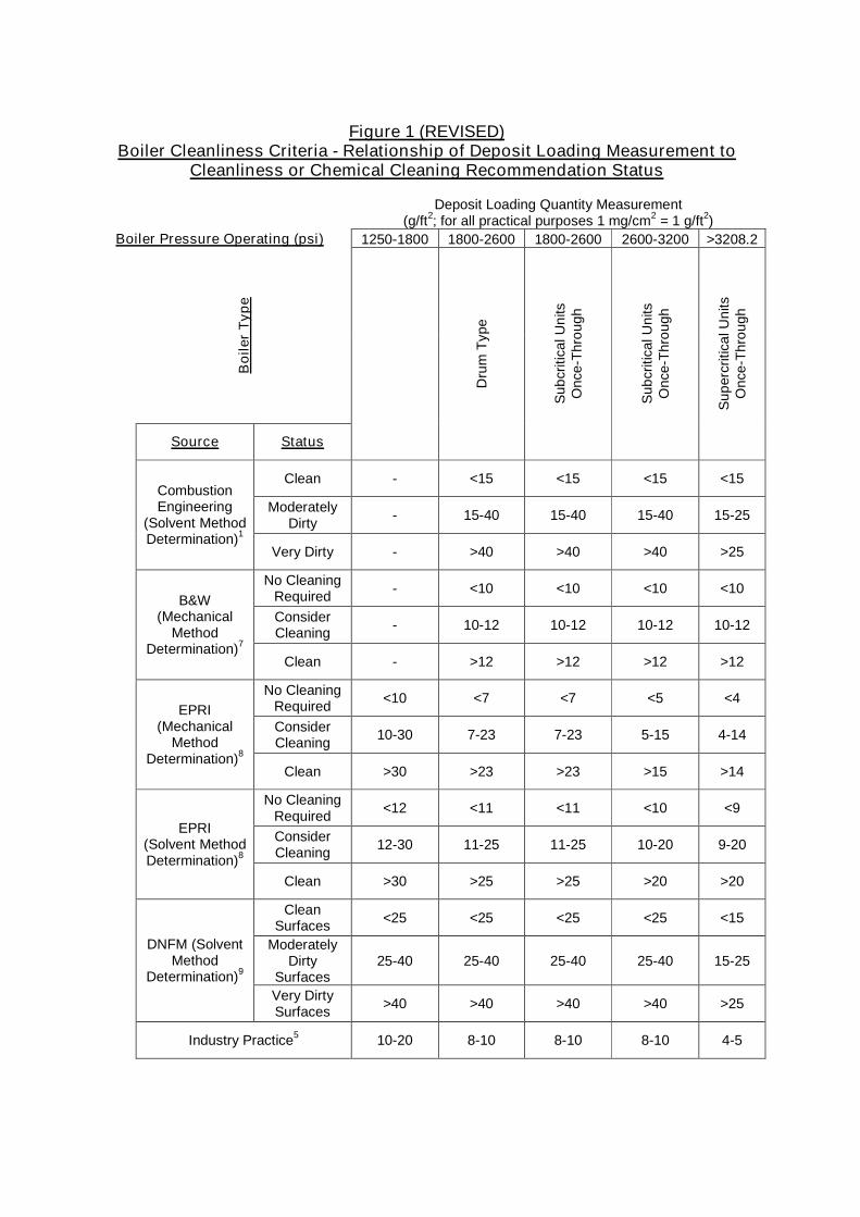
Figure 1 (REVISED)Boiler Cleanliness Criteria - Relationship of Deposit Loading Measurement to
Cleanliness or Chemical Cleaning Recommendation Status
Deposit Loading Quantity Measurement(g/ft2; for all practical purposes 1 mg/cm2 = 1 g/ft2)
Boiler Pressure Operating (psi) 1250-1800 1800-2600 1800-2600 2600-3200 >3208.2B
oile
rT
ype
Source Status
Dru
mT
ype
Sub
criti
calU
nits
Onc
e-Th
roug
h
Sub
criti
calU
nits
Onc
e-Th
roug
h
Sup
ercr
itica
lUni
tsO
nce-
Thro
ugh
Clean - <15 <15 <15 <15
ModeratelyDirty - 15-40 15-40 15-40 15-25
CombustionEngineering
(Solvent MethodDetermination)1
Very Dirty - >40 >40 >40 >25
No CleaningRequired - <10 <10 <10 <10
ConsiderCleaning - 10-12 10-12 10-12 10-12
B&W(Mechanical
MethodDetermination)7
Clean - >12 >12 >12 >12
No CleaningRequired <10 <7 <7 <5 <4
ConsiderCleaning 10-30 7-23 7-23 5-15 4-14
EPRI(Mechanical
MethodDetermination)8
Clean >30 >23 >23 >15 >14
No CleaningRequired <12 <11 <11 <10 <9
ConsiderCleaning 12-30 11-25 11-25 10-20 9-20
EPRI(Solvent MethodDetermination)8
Clean >30 >25 >25 >20 >20
CleanSurfaces <25 <25 <25 <25 <15
ModeratelyDirty
Surfaces25-40 25-40 25-40 25-40 15-25
DNFM (SolventMethod
Determination)9
Very DirtySurfaces >40 >40 >40 >40 >25
Industry Practice5 10-20 8-10 8-10 8-10 4-5
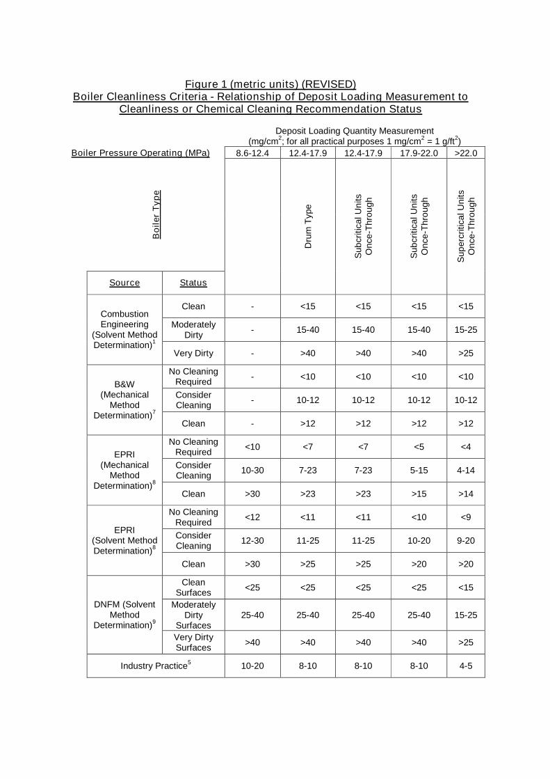
Figure 1 (metric units) (REVISED)Boiler Cleanliness Criteria - Relationship of Deposit Loading Measurement to
Cleanliness or Chemical Cleaning Recommendation Status
Deposit Loading Quantity Measurement(mg/cm2; for all practical purposes 1 mg/cm2 = 1 g/ft2)
Boiler Pressure Operating (MPa) 8.6-12.4 12.4-17.9 12.4-17.9 17.9-22.0 >22.0B
oile
rT
ype
Source Status
Dru
mT
ype
Sub
criti
calU
nits
Onc
e-Th
roug
h
Sub
criti
calU
nits
Onc
e-Th
roug
h
Sup
ercr
itica
lUni
tsO
nce-
Thro
ugh
Clean - <15 <15 <15 <15
ModeratelyDirty - 15-40 15-40 15-40 15-25
CombustionEngineering
(Solvent MethodDetermination)1
Very Dirty - >40 >40 >40 >25
No CleaningRequired - <10 <10 <10 <10
ConsiderCleaning - 10-12 10-12 10-12 10-12
B&W(Mechanical
MethodDetermination)7
Clean - >12 >12 >12 >12
No CleaningRequired <10 <7 <7 <5 <4
ConsiderCleaning 10-30 7-23 7-23 5-15 4-14
EPRI(Mechanical
MethodDetermination)8
Clean >30 >23 >23 >15 >14
No CleaningRequired <12 <11 <11 <10 <9
ConsiderCleaning 12-30 11-25 11-25 10-20 9-20
EPRI(Solvent MethodDetermination)8
Clean >30 >25 >25 >20 >20
CleanSurfaces <25 <25 <25 <25 <15
ModeratelyDirty
Surfaces25-40 25-40 25-40 25-40 15-25
DNFM (SolventMethod
Determination)9
Very DirtySurfaces >40 >40 >40 >40 >25
Industry Practice5 10-20 8-10 8-10 8-10 4-5
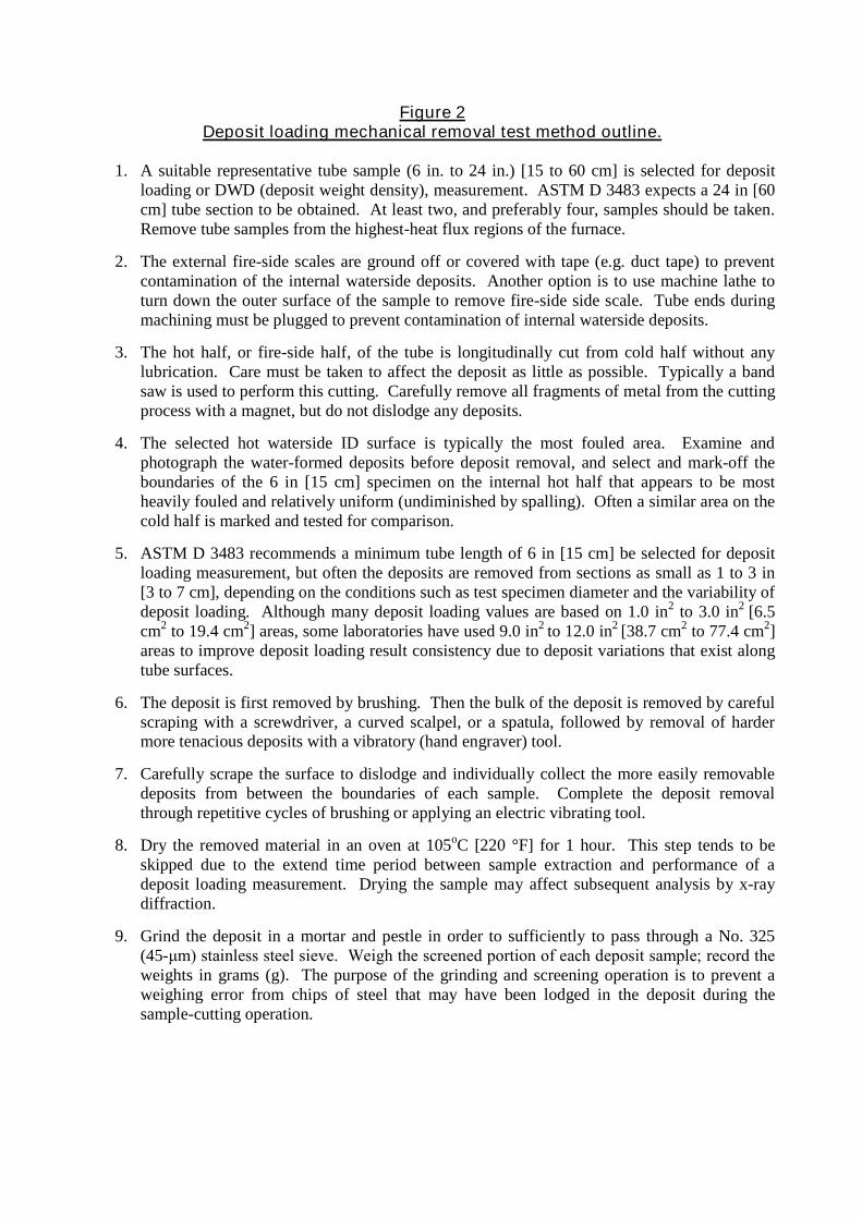
Figure 2Deposit loading mechanical removal test method outline.
1. A suitable representative tube sample (6 in. to 24 in.) [15 to 60 cm] is selected for depositloading or DWD (deposit weight density), measurement. ASTM D 3483 expects a 24 in [60cm] tube section to be obtained. At least two, and preferably four, samples should be taken.Remove tube samples from the highest-heat flux regions of the furnace.
2. The external fire-side scales are ground off or covered with tape (e.g. duct tape) to preventcontamination of the internal waterside deposits. Another option is to use machine lathe toturn down the outer surface of the sample to remove fire-side side scale. Tube ends duringmachining must be plugged to prevent contamination of internal waterside deposits.
3. The hot half, or fire-side half, of the tube is longitudinally cut from cold half without anylubrication. Care must be taken to affect the deposit as little as possible. Typically a bandsaw is used to perform this cutting. Carefully remove all fragments of metal from the cuttingprocess with a magnet, but do not dislodge any deposits.
4. The selected hot waterside ID surface is typically the most fouled area. Examine andphotograph the water-formed deposits before deposit removal, and select and mark-off theboundaries of the 6 in [15 cm] specimen on the internal hot half that appears to be mostheavily fouled and relatively uniform (undiminished by spalling). Often a similar area on thecold half is marked and tested for comparison.
5. ASTM D 3483 recommends a minimum tube length of 6 in [15 cm] be selected for depositloading measurement, but often the deposits are removed from sections as small as 1 to 3 in[3 to 7 cm], depending on the conditions such as test specimen diameter and the variability ofdeposit loading. Although many deposit loading values are based on 1.0 in2 to 3.0 in2 [6.5cm2 to 19.4 cm2] areas, some laboratories have used 9.0 in2 to 12.0 in2 [38.7 cm2 to 77.4 cm2]areas to improve deposit loading result consistency due to deposit variations that exist alongtube surfaces.
6. The deposit is first removed by brushing. Then the bulk of the deposit is removed by carefulscraping with a screwdriver, a curved scalpel, or a spatula, followed by removal of hardermore tenacious deposits with a vibratory (hand engraver) tool.
7. Carefully scrape the surface to dislodge and individually collect the more easily removabledeposits from between the boundaries of each sample. Complete the deposit removalthrough repetitive cycles of brushing or applying an electric vibrating tool.
8. Dry the removed material in an oven at 105oC [220 °F] for 1 hour. This step tends to beskipped due to the extend time period between sample extraction and performance of adeposit loading measurement. Drying the sample may affect subsequent analysis by x-raydiffraction.
9. Grind the deposit in a mortar and pestle in order to sufficiently to pass through a No. 325(45-μm) stainless steel sieve. Weigh the screened portion of each deposit sample; record the weights in grams (g). The purpose of the grinding and screening operation is to prevent aweighing error from chips of steel that may have been lodged in the deposit during thesample-cutting operation.
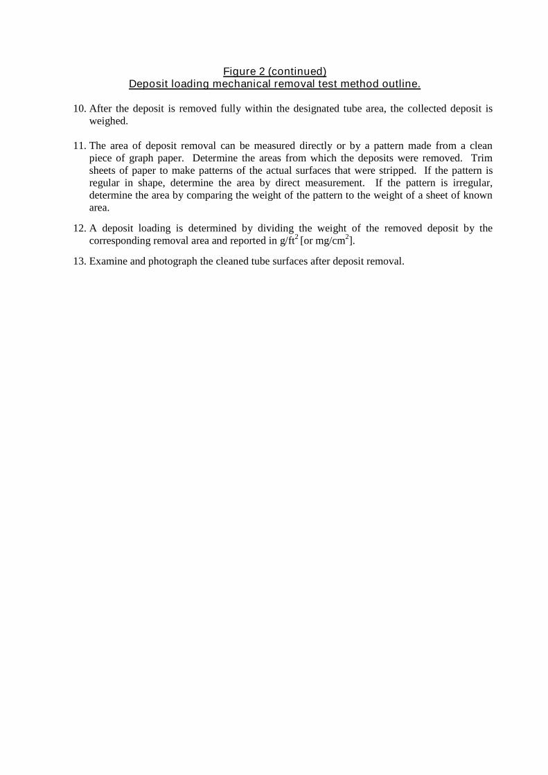
Figure 2 (continued)Deposit loading mechanical removal test method outline.
10. After the deposit is removed fully within the designated tube area, the collected deposit isweighed.
11. The area of deposit removal can be measured directly or by a pattern made from a cleanpiece of graph paper. Determine the areas from which the deposits were removed. Trimsheets of paper to make patterns of the actual surfaces that were stripped. If the pattern isregular in shape, determine the area by direct measurement. If the pattern is irregular,determine the area by comparing the weight of the pattern to the weight of a sheet of knownarea.
12. A deposit loading is determined by dividing the weight of the removed deposit by thecorresponding removal area and reported in g/ft2 [or mg/cm2].
13. Examine and photograph the cleaned tube surfaces after deposit removal.
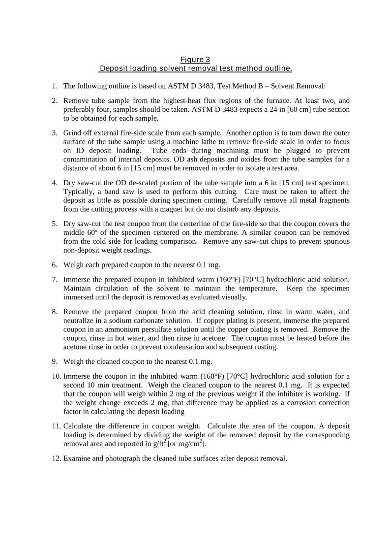
Figure 3Deposit loading solvent removal test method outline.
1. The following outline is based on ASTM D 3483, Test Method B–Solvent Removal:
2. Remove tube sample from the highest-heat flux regions of the furnace. At least two, andpreferably four, samples should be taken. ASTM D 3483 expects a 24 in [60 cm] tube sectionto be obtained for each sample.
3. Grind off external fire-side scale from each sample. Another option is to turn down the outersurface of the tube sample using a machine lathe to remove fire-side scale in order to focuson ID deposit loading. Tube ends during machining must be plugged to preventcontamination of internal deposits. OD ash deposits and oxides from the tube samples for adistance of about 6 in [15 cm] must be removed in order to isolate a test area.
4. Dry saw-cut the OD de-scaled portion of the tube sample into a 6 in [15 cm] test specimen.Typically, a band saw is used to perform this cutting. Care must be taken to affect thedeposit as little as possible during specimen cutting. Carefully remove all metal fragmentsfrom the cutting process with a magnet but do not disturb any deposits.
5. Dry saw-cut the test coupon from the centerline of the fire-side so that the coupon covers themiddle 60º of the specimen centered on the membrane. A similar coupon can be removedfrom the cold side for loading comparison. Remove any saw-cut chips to prevent spuriousnon-deposit weight readings.
6. Weigh each prepared coupon to the nearest 0.1 mg.
7. Immerse the prepared coupon in inhibited warm (160°F) [70°C] hydrochloric acid solution.Maintain circulation of the solvent to maintain the temperature. Keep the specimenimmersed until the deposit is removed as evaluated visually.
8. Remove the prepared coupon from the acid cleaning solution, rinse in warm water, andneutralize in a sodium carbonate solution. If copper plating is present, immerse the preparedcoupon in an ammonium persulfate solution until the copper plating is removed. Remove thecoupon, rinse in hot water, and then rinse in acetone. The coupon must be heated before theacetone rinse in order to prevent condensation and subsequent rusting.
9. Weigh the cleaned coupon to the nearest 0.1 mg.
10. Immerse the coupon in the inhibited warm (160°F) [70°C] hydrochloric acid solution for asecond 10 min treatment. Weigh the cleaned coupon to the nearest 0.1 mg. It is expectedthat the coupon will weigh within 2 mg of the previous weight if the inhibiter is working. Ifthe weight change exceeds 2 mg, that difference may be applied as a corrosion correctionfactor in calculating the deposit loading
11. Calculate the difference in coupon weight. Calculate the area of the coupon. A depositloading is determined by dividing the weight of the removed deposit by the correspondingremoval area and reported in g/ft2 [or mg/cm2].
12. Examine and photograph the cleaned tube surfaces after deposit removal.
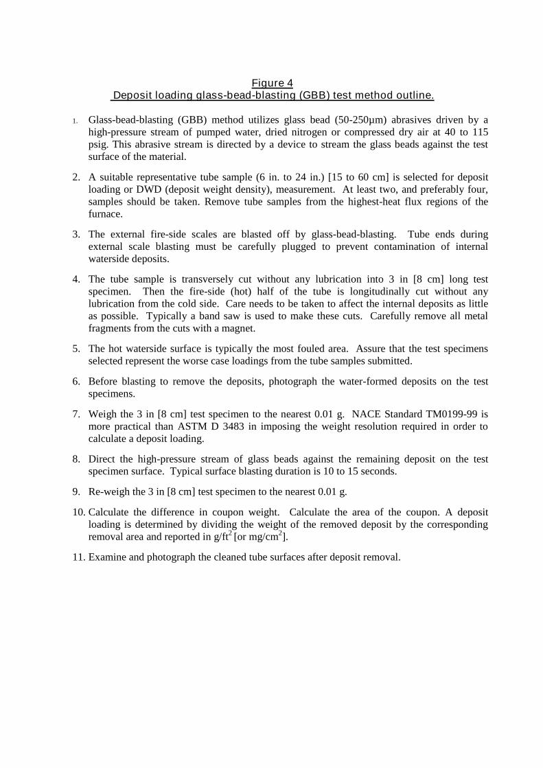
Figure 4Deposit loading glass-bead-blasting (GBB) test method outline.
1. Glass-bead-blasting (GBB) method utilizes glass bead (50-250µm) abrasives driven by ahigh-pressure stream of pumped water, dried nitrogen or compressed dry air at 40 to 115psig. This abrasive stream is directed by a device to stream the glass beads against the testsurface of the material.
2. A suitable representative tube sample (6 in. to 24 in.) [15 to 60 cm] is selected for depositloading or DWD (deposit weight density), measurement. At least two, and preferably four,samples should be taken. Remove tube samples from the highest-heat flux regions of thefurnace.
3. The external fire-side scales are blasted off by glass-bead-blasting. Tube ends duringexternal scale blasting must be carefully plugged to prevent contamination of internalwaterside deposits.
4. The tube sample is transversely cut without any lubrication into 3 in [8 cm] long testspecimen. Then the fire-side (hot) half of the tube is longitudinally cut without anylubrication from the cold side. Care needs to be taken to affect the internal deposits as littleas possible. Typically a band saw is used to make these cuts. Carefully remove all metalfragments from the cuts with a magnet.
5. The hot waterside surface is typically the most fouled area. Assure that the test specimensselected represent the worse case loadings from the tube samples submitted.
6. Before blasting to remove the deposits, photograph the water-formed deposits on the testspecimens.
7. Weigh the 3 in [8 cm] test specimen to the nearest 0.01 g. NACE Standard TM0199-99 ismore practical than ASTM D 3483 in imposing the weight resolution required in order tocalculate a deposit loading.
8. Direct the high-pressure stream of glass beads against the remaining deposit on the testspecimen surface. Typical surface blasting duration is 10 to 15 seconds.
9. Re-weigh the 3 in [8 cm] test specimen to the nearest 0.01 g.
10. Calculate the difference in coupon weight. Calculate the area of the coupon. A depositloading is determined by dividing the weight of the removed deposit by the correspondingremoval area and reported in g/ft2 [or mg/cm2].
11. Examine and photograph the cleaned tube surfaces after deposit removal.
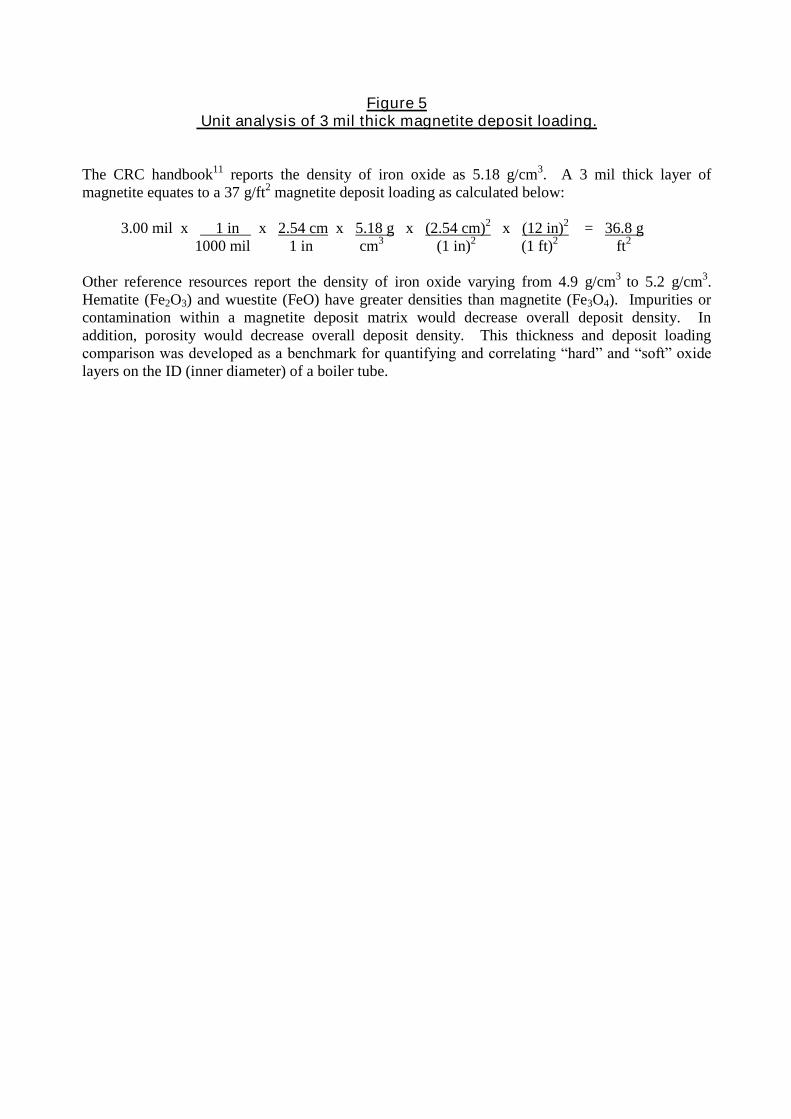
Figure 5Unit analysis of 3 mil thick magnetite deposit loading.
The CRC handbook11 reports the density of iron oxide as 5.18 g/cm3. A 3 mil thick layer ofmagnetite equates to a 37 g/ft2 magnetite deposit loading as calculated below:
3.00 mil x 1 in x 2.54 cm x 5.18 g x (2.54 cm)2 x (12 in)2 = 36.8 g1000 mil 1 in cm3 (1 in)2 (1 ft)2 ft2
Other reference resources report the density of iron oxide varying from 4.9 g/cm3 to 5.2 g/cm3.Hematite (Fe2O3) and wuestite (FeO) have greater densities than magnetite (Fe3O4). Impurities orcontamination within a magnetite deposit matrix would decrease overall deposit density. Inaddition, porosity would decrease overall deposit density. This thickness and deposit loadingcomparison was developed as a benchmark for quantifying and correlating “hard” and “soft” oxide layers on the ID (inner diameter) of a boiler tube.