nailor - submittal, model d0110 (type a), dynamic …...dynamic curtain type fire damper 1 1/2 hr....
TRANSCRIPT
QUALIFICATIONS:• UL 555 & CAN/ULC-S112 CLASSIFIED DYNAMIC FIRE DAMPER.
1 1/2 hr. label (File # R9492).• Meets all the requirements of UL and NFPA 80, 90A and 101 for fire
dampers in dynamic HVAC systems, as well as IBC and NBC (Canada)Building Code requirements.
• City of New York Board of Standards and Appeals. Cal. No. 460-88-SA.• California State Fire Marshal: Fire Damper Listing No. 3225-0935:0113.• Maximum velocity: 4000 fpm @ 4" w.g. (20 m/s @ 1 kPa).
VERTICAL MOUNT
HEIG
HT =
NOM
INAL
DUCT
SIZ
E - 1
/4" (
6)
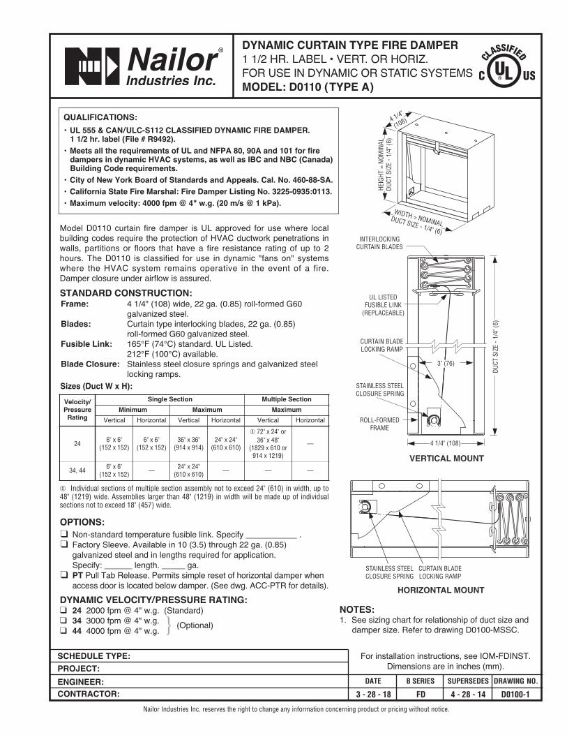
INTERLOCKINGCURTAIN BLADES
WIDTH = NOMINALDUCT SIZE - 1/4" (6)
4 1/4"
(108)
ROLL-FORMEDFRAME
UL LISTEDFUSIBLE LINK
(REPLACEABLE)
4 1/4" (108)
DUCT
SIZ
E - 1
/4" (
6)
STAINLESS STEELCLOSURE SPRING
CURTAIN BLADELOCKING RAMP
HORIZONTAL MOUNT
STAINLESS STEELCLOSURE SPRING
CURTAIN BLADELOCKING RAMP
3" (76)
SCHEDULE TYPE:PROJECT:ENGINEER:CONTRACTOR:
DATE B SERIES SUPERSEDES DRAWING NO.
3 - 28 - 18 FD 4 - 28 - 14 D0100-1
DYNAMIC CURTAIN TYPE FIRE DAMPER1 1/2 HR. LABEL • VERT. OR HORIZ.FOR USE IN DYNAMIC OR STATIC SYSTEMSMODEL: D0110 (TYPE A)
Nailor Industries Inc. reserves the right to change any information concerning product or pricing without notice.
For installation instructions, see IOM-FDINST.Dimensions are in inches (mm).
Model D0110 curtain fire damper is UL approved for use where localbuilding codes require the protection of HVAC ductwork penetrations inwalls, partitions or floors that have a fire resistance rating of up to 2hours. The D0110 is classified for use in dynamic "fans on" systemswhere the HVAC system remains operative in the event of a fire.Damper closure under airflow is assured.STANDARD CONSTRUCTION:Frame: 4 1/4" (108) wide, 22 ga. (0.85) roll-formed G60
galvanized steel.Blades: Curtain type interlocking blades, 22 ga. (0.85)
roll-formed G60 galvanized steel.Fusible Link: 165°F (74°C) standard. UL Listed.
212°F (100°C) available. Blade Closure: Stainless steel closure springs and galvanized steel
locking ramps. Sizes (Duct W x H):
� Individual sections of multiple section assembly not to exceed 24" (610) in width, up to48" (1219) wide. Assemblies larger than 48" (1219) in width will be made up of individualsections not to exceed 18" (457) wide.
OPTIONS:� Non-standard temperature fusible link. Specify ___________ .� Factory Sleeve. Available in 10 (3.5) through 22 ga. (0.85)galvanized steel and in lengths required for application. Specify: ______ length. _____ ga.
� PT Pull Tab Release. Permits simple reset of horizontal damper whenaccess door is located below damper. (See dwg. ACC-PTR for details).
DYNAMIC VELOCITY/PRESSURE RATING:� 24 2000 fpm @ 4" w.g. (Standard)� 34 3000 fpm @ 4" w.g.� 44 4000 fpm @ 4" w.g. (Optional)
Velocity/Pressure
Rating
Single Section Multiple SectionMinimum Maximum Maximum
Vertical Horizontal Vertical Horizontal Vertical Horizontal
24 6" x 6"(152 x 152)
6" x 6"(152 x 152)
36" x 36"(914 x 914)
24" x 24"(610 x 610)
� 72" x 24" or36" x 48"
(1829 x 610 or914 x 1219)
—
34, 44 6" x 6"(152 x 152) — 24" x 24"
(610 x 610) — — —
}NOTES:1. See sizing chart for relationship of duct size anddamper size. Refer to drawing D0100-MSSC.
QUALIFICATIONS:• UL 555 & CAN/ULC-S112 CLASSIFIED DYNAMIC FIRE DAMPER.
1 1/2 hr. label (File # R9492).• Meets all the requirements of UL and NFPA 80, 90A and 101 for fire
dampers in dynamic HVAC systems, as well as IBC and NBC (Canada)Building Code requirements.
• City of New York Board of Standards and Appeals. Cal. No. 460-88-SA.• California State Fire Marshal: Fire Damper Listing No. 3225-0935:0113.• Maximum velocity: 4000 fpm @ 4" w.g. (20 m/s @ 1 kPa).
SCHEDULE TYPE:PROJECT:ENGINEER:CONTRACTOR:
DATE B SERIES SUPERSEDES DRAWING NO.
3 - 28 - 18 FD 4 - 28 - 14 D0100-2
DYNAMIC CURTAIN TYPE FIRE DAMPER1 1/2 HR. LABEL • VERT. OR HORIZ.FOR USE IN DYNAMIC OR STATIC SYSTEMSMODEL: D0120 (TYPE B)
Nailor Industries Inc. reserves the right to change any information concerning product or pricing without notice.
For installation instructions, see IOM-FDINST.Dimensions are in inches (mm).
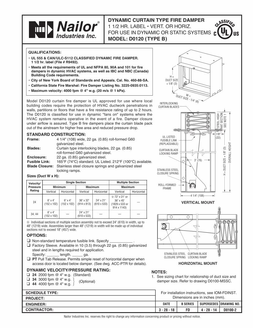
Model D0120 curtain fire damper is UL approved for use where localbuilding codes require the protection of HVAC ductwork penetrations inwalls, partitions or floors that have a fire resistance rating of up to 2 hours.The D0120 is classified for use in dynamic "fans on" systems where theHVAC system remains operative in the event of a fire. Damper closureunder airflow is assured. Type B fire dampers place the curtain blade packout of the airstream for higher free area and reduced pressure drop.STANDARD CONSTRUCTION:Frame: 4 1/4" (108) wide, 22 ga. (0.85) roll-formed G60
galvanized steel.Blades: Curtain type interlocking blades, 22 ga. (0.85)
roll-formed G60 galvanized steel.Enclosure: 22 ga. (0.85) galvanized steel. Fusible Link: 165°F (74°C) standard. UL Listed. 212°F (100°C) available. Blade Closure: Stainless steel closure springs and galvanized steel
locking ramps. Sizes (Duct W x H):
� Individual sections of multiple section assembly not to exceed 24" (610) in width, up to 48" (1219) wide. Assemblies larger than 48" (1219) in width will be made up of individualsections not to exceed 18" (457) wide.
OPTIONS:� Non-standard temperature fusible link. Specify ___________ .� Factory Sleeve. Available in 10 (3.5) through 22 ga. (0.85) galvanizedsteel and in lengths required for application. Specify: ______ length. _____ ga.
� PT Pull Tab Release. Permits simple reset of horizontal damper whenaccess door is located below damper. (See dwg. ACC-PTR for details).
DYNAMIC VELOCITY/PRESSURE RATING:� 24 2000 fpm @ 4" w.g. (Standard)� 34 3000 fpm @ 4" w.g.� 44 4000 fpm @ 4" w.g. (Optional)
VERTICAL MOUNT
H =DUCT SIZE+ 1/8" (3)
W =DUCT SIZE - 1/4" (6)
7/8"(22)
INTERLOCKINGCURTAIN BLADES
ROLL-FORMEDFRAME
UL LISTEDFUSIBLE LINK
(REPLACEABLE)
4 1/4" (108)
H =
DUCT
SIZ
E +
1/8"
(3)
OVER
ALL
HEIG
HT
STAINLESS STEELCLOSURE SPRING
CURTAIN BLADELOCKING RAMP
3" (76)
HORIZONTAL MOUNT
STAINLESS STEELCLOSURE SPRING
CURTAIN BLADELOCKING RAMP
STEE
L HI
GHHA
T SE
CTIO
NSE
E NO
TE 1
Velocity/Pressure
Rating
Single Section Multiple SectionMinimum Maximum Maximum
Vertical Horizontal Vertical Horizontal Vertical Horizontal
24 6" x 4"(152 x 102)
6" x 4"(152 x 102)
36" x 32"(914 x 813)
24" x 21"(610 x 533)
� 72" x 21" or36" x 45"
(1829 x 533 or914 x 1143)
—
34, 44 6" x 4"(152 x 102) — 24" x 21"
(610 x 533) — — —
NOTES:1. See sizing chart for relationship of duct size anddamper size. Refer to drawing D0100-MSSC.}
QUALIFICATIONS:• UL 555 & CAN/ULC-S112 CLASSIFIED DYNAMIC FIRE DAMPER.
1 1/2 hr. label (File # R9492).• Meets all the requirements of UL and NFPA 80, 90A and 101 for fire
dampers in dynamic HVAC systems, as well as IBC and NBC(Canada) Building Code requirements.
• City of New York Board of Standards and Appeals. Cal. No. 460-88-SA.• California State Fire Marshal: Fire Damper Listing No. 3225-0935:0113.• Maximum velocity: 4000 fpm @ 4" w.g. (20 m/s @ 1 kPa).
SCHEDULE TYPE:PROJECT:ENGINEER:CONTRACTOR:
DATE B SERIES SUPERSEDES DRAWING NO.
3 - 28 - 18 FD 4 - 28 - 14 D0100-3
DYNAMIC CURTAIN TYPE FIRE DAMPER1 1/2 HR. LABEL • VERT. OR HORIZ.FOR USE IN DYNAMIC OR STATIC SYSTEMSMODEL: D0130 (TYPES CR & CO)
Nailor Industries Inc. reserves the right to change any information concerning product or pricing without notice.
For installation instructions, see IOM-FDINST.Dimensions are in inches (mm).
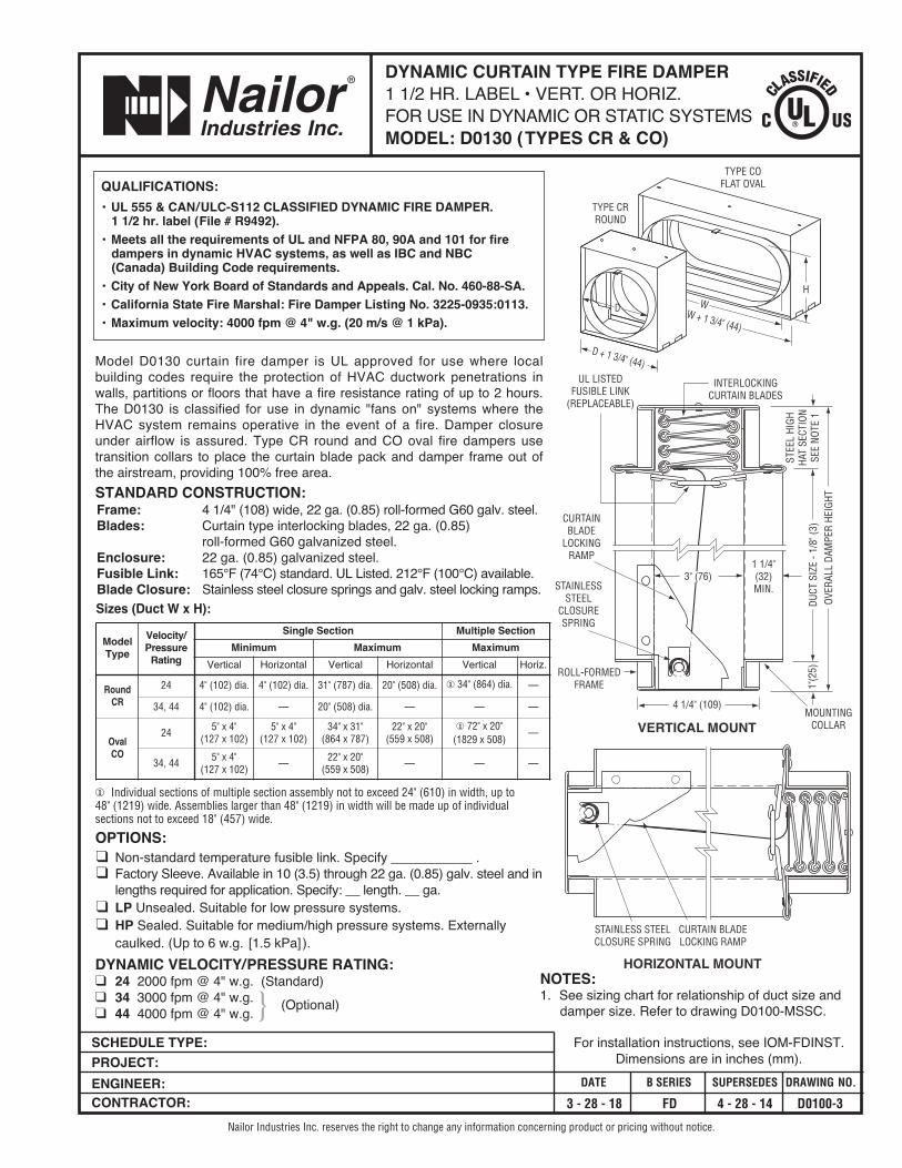
Model D0130 curtain fire damper is UL approved for use where localbuilding codes require the protection of HVAC ductwork penetrations inwalls, partitions or floors that have a fire resistance rating of up to 2 hours.The D0130 is classified for use in dynamic "fans on" systems where theHVAC system remains operative in the event of a fire. Damper closureunder airflow is assured. Type CR round and CO oval fire dampers usetransition collars to place the curtain blade pack and damper frame out ofthe airstream, providing 100% free area.STANDARD CONSTRUCTION:Frame: 4 1/4" (108) wide, 22 ga. (0.85) roll-formed G60 galv. steel.Blades: Curtain type interlocking blades, 22 ga. (0.85)
roll-formed G60 galvanized steel.Enclosure: 22 ga. (0.85) galvanized steel. Fusible Link: 165°F (74°C) standard. UL Listed. 212°F (100°C) available. Blade Closure: Stainless steel closure springs and galv. steel locking ramps. Sizes (Duct W x H):
� Individual sections of multiple section assembly not to exceed 24" (610) in width, up to 48" (1219) wide. Assemblies larger than 48" (1219) in width will be made up of individualsections not to exceed 18" (457) wide.
OPTIONS:� Non-standard temperature fusible link. Specify ___________ .� Factory Sleeve. Available in 10 (3.5) through 22 ga. (0.85) galv. steel and inlengths required for application. Specify: __ length. __ ga.
� LP Unsealed. Suitable for low pressure systems.� HP Sealed. Suitable for medium/high pressure systems. Externallycaulked. (Up to 6 w.g. [1.5 kPa]).
DYNAMIC VELOCITY/PRESSURE RATING:� 24 2000 fpm @ 4" w.g. (Standard)� 34 3000 fpm @ 4" w.g.� 44 4000 fpm @ 4" w.g. (Optional)
TYPE COFLAT OVAL
D + 1 3/4" (44)
D
TYPE CRROUND
W + 1 3/4" (44)
WH
VERTICAL MOUNT
4 1/4" (109)
UL LISTEDFUSIBLE LINK
(REPLACEABLE)
INTERLOCKINGCURTAIN BLADES
ROLL-FORMEDFRAME
DUCT
SIZ
E - 1
/8" (
3)OV
ERAL
L DA
MPE
R HE
IGHT
MOUNTINGCOLLAR
1 1/4"(32)MIN.
STEE
L HI
GHHA
T SE
CTIO
NSE
E NO
TE 1
1"(2
5)
STAINLESSSTEEL
CLOSURESPRING
CURTAINBLADE
LOCKINGRAMP
HORIZONTAL MOUNT
STAINLESS STEELCLOSURE SPRING
CURTAIN BLADELOCKING RAMP
3" (76)
NOTES:1. See sizing chart for relationship of duct size and
damper size. Refer to drawing D0100-MSSC.
ModelType
Velocity/Pressure
Rating
Single Section Multiple SectionMinimum Maximum Maximum
Vertical Horizontal Vertical Horizontal Vertical Horiz.
RoundCR
24 4" (102) dia. 4" (102) dia. 31" (787) dia. 20" (508) dia. � 34" (864) dia. —
34, 44 4" (102) dia. — 20" (508) dia. — — —
OvalCO
24 5" x 4"(127 x 102)
5" x 4"(127 x 102)
34" x 31"(864 x 787)
22" x 20"(559 x 508)
� 72" x 20"(1829 x 508)
—
34, 44 5" x 4"(127 x 102) — 22" x 20"
(559 x 508) — — —
}
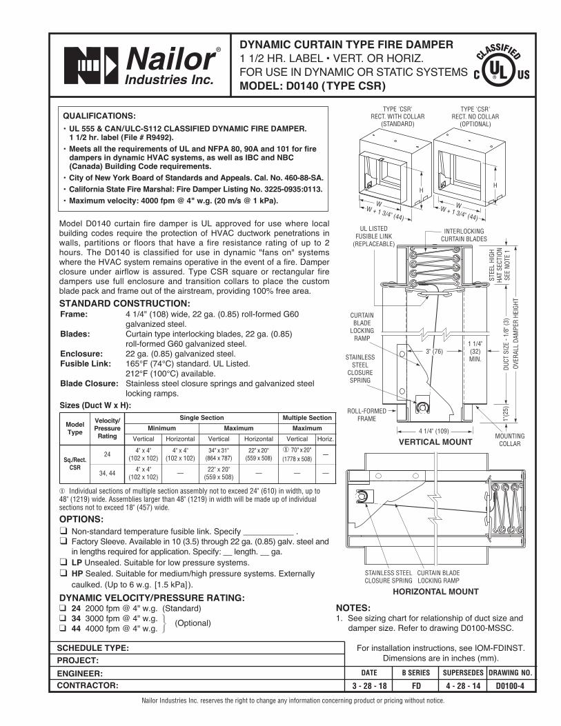
TYPE 'CSR'RECT. NO COLLAR
(OPTIONAL)
TYPE 'CSR'RECT. WITH COLLAR
(STANDARD)
HH
W + 1 3/4" (44)
WW + 1 3/4" (44)
W
4 1/4" (109)
UL LISTEDFUSIBLE LINK
(REPLACEABLE)
INTERLOCKINGCURTAIN BLADES
ROLL-FORMEDFRAME
DUCT
SIZ
E - 1
/8" (
3)OV
ERAL
L DA
MPE
R HE
IGHT
MOUNTINGCOLLAR
1 1/4"(32)MIN.
STEE
L HI
GHHA
T SE
CTIO
NSE
E NO
TE 1
1"(2
5)
STAINLESSSTEEL
CLOSURESPRING
CURTAINBLADE
LOCKINGRAMP
VERTICAL MOUNT
HORIZONTAL MOUNT
STAINLESS STEELCLOSURE SPRING
CURTAIN BLADELOCKING RAMP
3" (76)
Model D0140 curtain fire damper is UL approved for use where localbuilding codes require the protection of HVAC ductwork penetrations inwalls, partitions or floors that have a fire resistance rating of up to 2hours. The D0140 is classified for use in dynamic "fans on" systemswhere the HVAC system remains operative in the event of a fire. Damperclosure under airflow is assured. Type CSR square or rectangular firedampers use full enclosure and transition collars to place the customblade pack and frame out of the airstream, providing 100% free area.STANDARD CONSTRUCTION:Frame: 4 1/4" (108) wide, 22 ga. (0.85) roll-formed G60
galvanized steel.Blades: Curtain type interlocking blades, 22 ga. (0.85)
roll-formed G60 galvanized steel.Enclosure: 22 ga. (0.85) galvanized steel. Fusible Link: 165°F (74°C) standard. UL Listed.
212°F (100°C) available. Blade Closure: Stainless steel closure springs and galvanized steel
locking ramps. Sizes (Duct W x H):
� Individual sections of multiple section assembly not to exceed 24" (610) in width, up to 48" (1219) wide. Assemblies larger than 48" (1219) in width will be made up of individualsections not to exceed 18" (457) wide.
OPTIONS:� Non-standard temperature fusible link. Specify ___________ .� Factory Sleeve. Available in 10 (3.5) through 22 ga. (0.85) galv. steel andin lengths required for application. Specify: __ length. __ ga.
� LP Unsealed. Suitable for low pressure systems.� HP Sealed. Suitable for medium/high pressure systems. Externallycaulked. (Up to 6 w.g. [1.5 kPa]).
DYNAMIC VELOCITY/PRESSURE RATING:� 24 2000 fpm @ 4" w.g. (Standard)� 34 3000 fpm @ 4" w.g.� 44 4000 fpm @ 4" w.g. (Optional)
QUALIFICATIONS:• UL 555 & CAN/ULC-S112 CLASSIFIED DYNAMIC FIRE DAMPER.
1 1/2 hr. label (File # R9492).• Meets all the requirements of UL and NFPA 80, 90A and 101 for fire
dampers in dynamic HVAC systems, as well as IBC and NBC(Canada) Building Code requirements.
• City of New York Board of Standards and Appeals. Cal. No. 460-88-SA.• California State Fire Marshal: Fire Damper Listing No. 3225-0935:0113.• Maximum velocity: 4000 fpm @ 4" w.g. (20 m/s @ 1 kPa).
SCHEDULE TYPE:PROJECT:ENGINEER:CONTRACTOR:
DATE B SERIES SUPERSEDES DRAWING NO.
3 - 28 - 18 FD 4 - 28 - 14 D0100-4
DYNAMIC CURTAIN TYPE FIRE DAMPER1 1/2 HR. LABEL • VERT. OR HORIZ.FOR USE IN DYNAMIC OR STATIC SYSTEMSMODEL: D0140 (TYPE CSR)
Nailor Industries Inc. reserves the right to change any information concerning product or pricing without notice.
For installation instructions, see IOM-FDINST.Dimensions are in inches (mm).
NOTES:1. See sizing chart for relationship of duct size and
damper size. Refer to drawing D0100-MSSC.
ModelType
Velocity/Pressure
Rating
Single Section Multiple SectionMinimum Maximum Maximum
Vertical Horizontal Vertical Horizontal Vertical Horiz.
Sq./Rect.CSR
24 4" x 4"(102 x 102)
4" x 4"(102 x 102)
34" x 31"(864 x 787)
22" x 20"(559 x 508)
� 70" x 20"(1778 x 508)
—
34, 44 4" x 4"(102 x 102) — 22" x 20"
(559 x 508) — — —
}
QUALIFICATIONS:• UL 555 & CAN/ULC-S112 CLASSIFIED DYNAMIC FIRE DAMPER.
1 1/2 hr. label (File # R9492).• Meets all the requirements of UL and NFPA 80, 90A and 101 for fire
dampers in dynamic HVAC systems, as well as IBC and NBC (Canada) Building Code requirements.
• City of New York Board of Standards and Appeals. Cal. No. 460-88-SA.• California State Fire Marshal: Fire Damper Listing No. 3225-0935:0113.• Maximum velocity: 2000 fpm @ 4" w.g. (10 m/s @ 1 kPa).
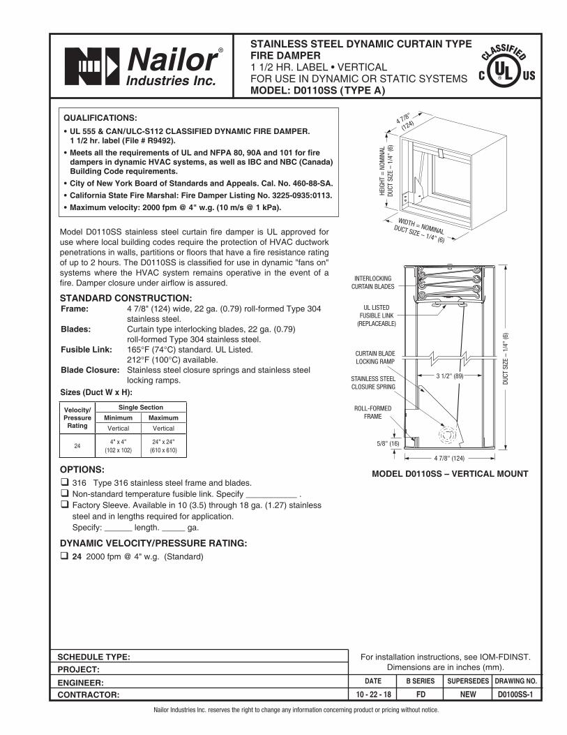
MODEL D0110SS – VERTICAL MOUNT
HEIG
HT =
NOM
INAL
DUCT
SIZ
E –
1/4"
(6)
INTERLOCKINGCURTAIN BLADES
WIDTH = NOMINALDUCT SIZE – 1/4" (6)
4 7/8"
(124)
ROLL-FORMEDFRAME
UL LISTEDFUSIBLE LINK
(REPLACEABLE)
4 7/8" (124)
DUCT
SIZ
E –
1/4"
(6)
STAINLESS STEELCLOSURE SPRING
CURTAIN BLADELOCKING RAMP
3 1/2" (89)
5/8" (16)
SCHEDULE TYPE: PROJECT: ENGINEER: CONTRACTOR:
DATE B SERIES SUPERSEDES DRAWING NO.
10 - 22 - 18 FD NEW D0100SS-1
STAINLESS STEEL DYNAMIC CURTAIN TYPEFIRE DAMPER1 1/2 HR. LABEL • VERTICALFOR USE IN DYNAMIC OR STATIC SYSTEMSMODEL: D0110SS (TYPE A)
Nailor Industries Inc. reserves the right to change any information concerning product or pricing without notice.
For installation instructions, see IOM-FDINST.Dimensions are in inches (mm).
Model D0110SS stainless steel curtain fire damper is UL approved for use where local building codes require the protection of HVAC ductwork penetrations in walls, partitions or floors that have a fire resistance rating of up to 2 hours. The D0110SS is classified for use in dynamic "fans on" systems where the HVAC system remains operative in the event of a fire. Damper closure under airflow is assured.
STANDARD CONSTRUCTION:Frame: 4 7/8" (124) wide, 22 ga. (0.79) roll-formed Type 304
stainless steel.Blades: Curtain type interlocking blades, 22 ga. (0.79)
roll-formed Type 304 stainless steel.Fusible Link: 165°F (74°C) standard. UL Listed.
212°F (100°C) available. Blade Closure: Stainless steel closure springs and stainless steel
locking ramps. Sizes (Duct W x H):
OPTIONS:q 316 Type 316 stainless steel frame and blades.q Non-standard temperature fusible link. Specify ___________ .q Factory Sleeve. Available in 10 (3.5) through 18 ga. (1.27) stainless
steel and in lengths required for application. Specify: ______ length. _____ ga.
DYNAMIC VELOCITY/PRESSURE RATING:q 24 2000 fpm @ 4" w.g. (Standard)
Velocity/Pressure
Rating
Single SectionMinimum MaximumVertical Vertical
244" x 4"
(102 x 102)24" x 24"
(610 x 610)
QUALIFICATIONS:• UL 555 & CAN/ULC-S112 CLASSIFIED DYNAMIC FIRE DAMPER.
1 1/2 hr. label (File # R9492).• Meets all the requirements of UL and NFPA 80, 90A and 101 for fire
dampers in dynamic HVAC systems, as well as IBC and NBC (Canada) Building Code requirements.
• City of New York Board of Standards and Appeals. Cal. No. 460-88-SA.• California State Fire Marshal: Fire Damper Listing No. 3225-0935:0113.• Maximum velocity: 2000 fpm @ 4" w.g. (10 m/s @ 1 kPa).
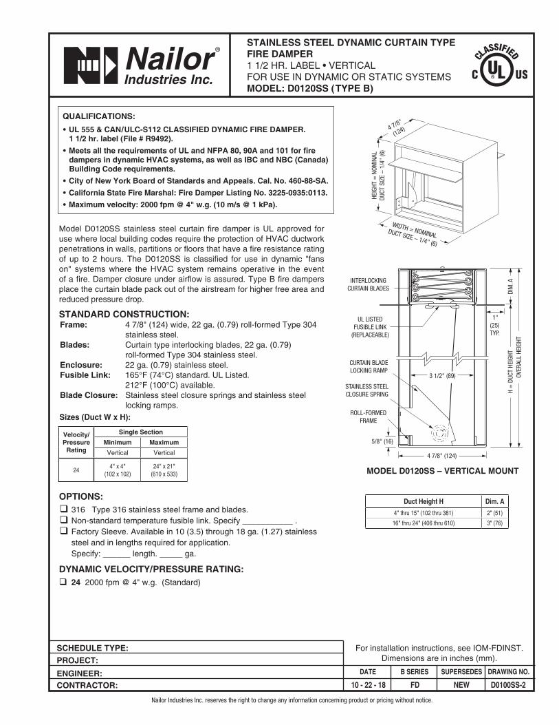
HEIG
HT =
NOM
INAL
DUCT
SIZ
E –
1/4"
(6)
WIDTH = NOMINALDUCT SIZE – 1/4" (6)
4 7/8"
(124)
MODEL D0120SS – VERTICAL MOUNT
INTERLOCKINGCURTAIN BLADES
ROLL-FORMEDFRAME
UL LISTEDFUSIBLE LINK
(REPLACEABLE)
4 7/8" (124)
H =
DUC
T HE
IGHT
OVER
ALL
HEIG
HTDI
M. A
STAINLESS STEELCLOSURE SPRING
CURTAIN BLADELOCKING RAMP
3 1/2" (89)
5/8" (16)
1"(25) TYP.
SCHEDULE TYPE: PROJECT: ENGINEER: CONTRACTOR:
DATE B SERIES SUPERSEDES DRAWING NO.
10 - 22 - 18 FD NEW D0100SS-2
STAINLESS STEEL DYNAMIC CURTAIN TYPEFIRE DAMPER1 1/2 HR. LABEL • VERTICAL FOR USE IN DYNAMIC OR STATIC SYSTEMSMODEL: D0120SS (TYPE B)
Nailor Industries Inc. reserves the right to change any information concerning product or pricing without notice.
For installation instructions, see IOM-FDINST.Dimensions are in inches (mm).
Model D0120SS stainless steel curtain fire damper is UL approved for use where local building codes require the protection of HVAC ductwork penetrations in walls, partitions or floors that have a fire resistance rating of up to 2 hours. The D0120SS is classified for use in dynamic "fans on" systems where the HVAC system remains operative in the event of a fire. Damper closure under airflow is assured. Type B fire dampers place the curtain blade pack out of the airstream for higher free area and reduced pressure drop.
STANDARD CONSTRUCTION:Frame: 4 7/8" (124) wide, 22 ga. (0.79) roll-formed Type 304
stainless steel.Blades: Curtain type interlocking blades, 22 ga. (0.79)
roll-formed Type 304 stainless steel.Enclosure: 22 ga. (0.79) stainless steel. Fusible Link: 165°F (74°C) standard. UL Listed.
212°F (100°C) available. Blade Closure: Stainless steel closure springs and stainless steel
locking ramps. Sizes (Duct W x H):
OPTIONS:q 316 Type 316 stainless steel frame and blades.q Non-standard temperature fusible link. Specify ___________ .q Factory Sleeve. Available in 10 (3.5) through 18 ga. (1.27) stainless
steel and in lengths required for application. Specify: ______ length. _____ ga.
DYNAMIC VELOCITY/PRESSURE RATING:q 24 2000 fpm @ 4" w.g. (Standard)
Velocity/Pressure
Rating
Single SectionMinimum MaximumVertical Vertical
244" x 4"
(102 x 102)24" x 21"
(610 x 533)
Duct Height H Dim. A
4" thru 15" (102 thru 381) 2" (51)
16" thru 24" (406 thru 610) 3" (76)
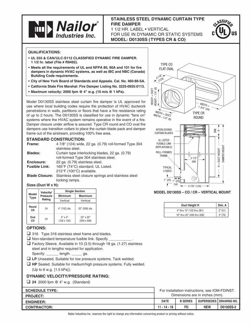
Model D0130SS stainless steel curtain fire damper is UL approved for use where local building codes require the protection of HVAC ductwork penetrations in walls, partitions or floors that have a fire resistance rating of up to 2 hours. The D0130SS is classified for use in dynamic "fans on" systems where the HVAC system remains operative in the event of a fire. Damper closure under airflow is assured. Type CR round and CO oval fire dampers use transition collars to place the curtain blade pack and damper frame out of the airstream, providing 100% free area.
STANDARD CONSTRUCTION:Frame: 4 7/8" (124) wide, 22 ga. (0.79) roll-formed Type 304
stainless steel.Blades: Curtain type interlocking blades, 22 ga. (0.79)
roll-formed Type 304 stainless steel.Enclosure: 22 ga. (0.79) stainless steel. Fusible Link: 165°F (74°C) standard. UL Listed.
212°F (100°C) available. Blade Closure: Stainless steel closure springs and stainless steel
locking ramps. Sizes (Duct W x H):
OPTIONS:q 316 Type 316 stainless steel frame and blades.q Non-standard temperature fusible link. Specify ___________ .q Factory Sleeve. Available in 10 (3.5) through 18 ga. (1.27) stainless
steel and in lengths required for application. Specify: ______ length. _____ ga.
q LP Unsealed. Suitable for low pressure systems. Tack welded.q HP Sealed. Suitable for medium/high pressure systems. Fully welded.
(Up to 6 w.g. [1.5 kPa]).
DYNAMIC VELOCITY/PRESSURE RATING:q 24 2000 fpm @ 4" w.g. (Standard)
ModelType
Velocity/Pressure
Rating
Single SectionMinimum Maximum
Vertical Vertical
RoundCR 24 4" (102) dia. 20" (508) dia.
OvalCO 24
4" x 4"(102 x 102)
22" x 20"(559 x 508)
QUALIFICATIONS:• UL 555 & CAN/ULC-S112 CLASSIFIED DYNAMIC FIRE DAMPER.
1 1/2 hr. label (File # R9492).• Meets all the requirements of UL and NFPA 80, 90A and 101 for fire
dampers in dynamic HVAC systems, as well as IBC and NBC (Canada) Building Code requirements.
• City of New York Board of Standards and Appeals. Cal. No. 460-88-SA.• California State Fire Marshal: Fire Damper Listing No. 3225-0935:0113.• Maximum velocity: 2000 fpm @ 4" w.g. (10 m/s @ 1 kPa).
HEIG
HT =
DUC
THE
IGHT
– 1
/4"
(6)
WIDTH = DUCTWIDTH – 1/4" (6)
4 7/8"
(124)
MODEL D0130SS – CO / CR – VERTICAL MOUNT
INTERLOCKINGCURTAIN BLADES
ROLL-FORMEDFRAME
UL LISTEDFUSIBLE LINK
(REPLACEABLE)
4 7/8" (124)
H =
DUC
T HE
IGHT
DAM
PER
HEIG
HT
DIM
.A
3 1/2"(89)
1" (25)
TYPICAL3 SIDES
1" (25)TYP.
WIDTH +1 3/4" (44)
TYPE COFLAT OVAL
TYPE CRROUND
SCHEDULE TYPE: PROJECT: ENGINEER: CONTRACTOR:
DATE B SERIES SUPERSEDES DRAWING NO.
11 - 14 - 18 FD NEW D0100SS-3
STAINLESS STEEL DYNAMIC CURTAIN TYPEFIRE DAMPER1 1/2 HR. LABEL • VERTICAL FOR USE IN DYNAMIC OR STATIC SYSTEMSMODEL: D0130SS (TYPES CR & CO)
Nailor Industries Inc. reserves the right to change any information concerning product or pricing without notice.
For installation instructions, see IOM-FDINST.Dimensions are in inches (mm).
Duct Height H Dim. A
4" thru 15" (102 thru 381) 2" (51)
16" thru 20" (406 thru 508) 3" (76)
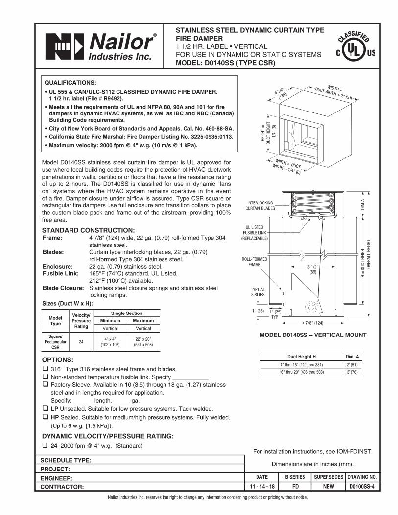
Model D0140SS stainless steel curtain fire damper is UL approved for use where local building codes require the protection of HVAC ductwork penetrations in walls, partitions or floors that have a fire resistance rating of up to 2 hours. The D0140SS is classified for use in dynamic "fans on" systems where the HVAC system remains operative in the event of a fire. Damper closure under airflow is assured. Type CSR square or rectangular fire dampers use full enclosure and transition collars to place the custom blade pack and frame out of the airstream, providing 100% free area.
STANDARD CONSTRUCTION:Frame: 4 7/8" (124) wide, 22 ga. (0.79) roll-formed Type 304
stainless steel.Blades: Curtain type interlocking blades, 22 ga. (0.79)
roll-formed Type 304 stainless steel.Enclosure: 22 ga. (0.79) stainless steel. Fusible Link: 165°F (74°C) standard. UL Listed.
212°F (100°C) available. Blade Closure: Stainless steel closure springs and stainless steel
locking ramps. Sizes (Duct W x H):
OPTIONS:q 316 Type 316 stainless steel frame and blades.q Non-standard temperature fusible link. Specify ___________ .q Factory Sleeve. Available in 10 (3.5) through 18 ga. (1.27) stainless
steel and in lengths required for application. Specify: ______ length. _____ ga.
q LP Unsealed. Suitable for low pressure systems. Tack welded.q HP Sealed. Suitable for medium/high pressure systems. Fully welded.
(Up to 6 w.g. [1.5 kPa]).
DYNAMIC VELOCITY/PRESSURE RATING:q 24 2000 fpm @ 4" w.g. (Standard)
ModelType
Velocity/Pressure
Rating
Single SectionMinimum Maximum
Vertical Vertical
Square/Rectangular
CSR24
4" x 4"(102 x 102)
22" x 20"(559 x 508)
QUALIFICATIONS:• UL 555 & CAN/ULC-S112 CLASSIFIED DYNAMIC FIRE DAMPER.
1 1/2 hr. label (File # R9492).• Meets all the requirements of UL and NFPA 80, 90A and 101 for fire
dampers in dynamic HVAC systems, as well as IBC and NBC (Canada) Building Code requirements.
• City of New York Board of Standards and Appeals. Cal. No. 460-88-SA.• California State Fire Marshal: Fire Damper Listing No. 3225-0935:0113.• Maximum velocity: 2000 fpm @ 4" w.g. (10 m/s @ 1 kPa).
HEIG
HT =
DUCT
HEI
GHT
– 1/
4" (6
)
WIDTH = DUCTWIDTH – 1/4" (6)
4 7/8"
(124)
MODEL D0140SS – VERTICAL MOUNT
INTERLOCKINGCURTAIN BLADES
ROLL-FORMEDFRAME
UL LISTEDFUSIBLE LINK
(REPLACEABLE)
4 7/8" (124)
H =
DUC
T HE
IGHT
OVER
ALL
HEIG
HTDI
M. A
3 1/2"(89)
1" (25)
TYPICAL3 SIDES
1" (25)TYP.
WIDTH =DUCT WIDTH + 2" (51)
SCHEDULE TYPE: PROJECT: ENGINEER: CONTRACTOR:
DATE B SERIES SUPERSEDES DRAWING NO.
11 - 14 - 18 FD NEW D0100SS-4
STAINLESS STEEL DYNAMIC CURTAIN TYPEFIRE DAMPER1 1/2 HR. LABEL • VERTICAL FOR USE IN DYNAMIC OR STATIC SYSTEMSMODEL: D0140SS (TYPE CSR)
Nailor Industries Inc. reserves the right to change any information concerning product or pricing without notice.
Dimensions are in inches (mm).
For installation instructions, see IOM-FDINST.
Duct Height H Dim. A
4" thru 15" (102 thru 381) 2” (51)
16" thru 20" (406 thru 508) 3” (76)
SCHEDULE TYPE:
PROJECT:
ENGINEER:CONTRACTOR:
DATE B SERIES SUPERSEDES DRAWING NO.
31 - 7 - 00R ACC 1 - 98R/0100-6 ACC.ETL
CURTAIN FIRE DAMPER ACCESSORYELECTRO-THERMAL LINKMODEL: ETL
Nailor Industries Inc. reserves the right to change any information concerning product or pricing without notice.
Nailor Industries Inc.
Dimensions are in inches (mm).
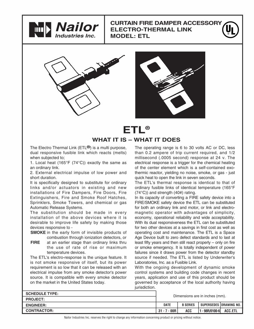
The Electro Thermal Link (ETL®) is a multi purpose,dual responsive fusible link which reacts (melts)when subjected to;1. Local heat (165°F (74°C)) exactly the same asan ordinary link.2. External electrical impulse of low power andshort duration.It is specifically designed to substitute for ordinarylinks and/or actuators in existing and newinstallations of Fire Dampers, Fire Doors, FireExtinguishers, Fire and Smoke Roof Hatches,Sprinklers, Smoke Towers, and chemical or gasAutomatic Release Systems.The substitution should be made in everyinstallation of the above devices where it isdesirable to improve life safety by making thosedevices responsive to -SMOKE in the early form of invisible products of
combustion through ionization detectors, orFIRE at an earlier stage than ordinary links thru
the use of rate of r ise or maximumtemperature devices.
The ETL's electro-response is the unique feature. Itis not smoke responsive of itself, but its powerrequirement is so low that it can be released with anelectrical impulse from any smoke detector's powersource. It is compatible with every smoke detectoron the market in the United States today.
The operating range is 6 to 30 volts AC or DC, lessthan 0.2 ampere of trip current required, and 1/2millisecond (.0005 second) response at 24 v. Theelectrical response is a trigger for the chemical heatingof the center element which is a self-contained exo-thermic reactor, yielding no noise, smoke, or gas - justquick heat to open the link in seven seconds.The ETL's thermal response is identical to that ofordinary fusible links of identical temperature (165°F(74°C)) and strength (40#) rating.In its capacity of converting a FIRE safety device into aFIRE/SMOKE safety device the ETL can be substitutedfor both an ordinary link and motor, or link and electro-magnetic operator with advantages of simplicity,economy, operational reliability and wide acceptability.With its dual responsiveness the ETL can be substitutedfor two other devices at a savings in first cost as well asoperating cost and maintenance. The ETL is a SpaceAge Device built to zero defect standards and to last atleast fifty years and then still react properly – only on fireor smoke emergency. It is totally independent of powerfailures since it draws power from the detector standbysource if needed. The ETL is listed by Underwriter'sLaboratories, Inc. as a Fusible Link.With the ongoing development of dynamic smokecontrol systems and building code changes in recentyears, application and use of this product should begoverned by acceptance of the local authority havingjurisdiction.
ETL®
WHAT IT IS – WHAT IT DOES
SCHEDULE TYPE:
PROJECT:
ENGINEER:CONTRACTOR:
DATE B SERIES SUPERSEDES DRAWING NO.
3- 10 - 00R ACC-PTR 7-90/0100-16 ACC-PTR
PULL TAB RELEASE FOR CURTAIN TYPE FIRE DAMPERSACCESSORY FOR STANDARD AND WIDE FRAMETYPE A AND B SPRING LOADED MODELS
Nailor Industries Inc. reserves the right to change any information concerning product or pricing without notice.
Nailor Industries Inc.
Dimensions are in inches (mm).
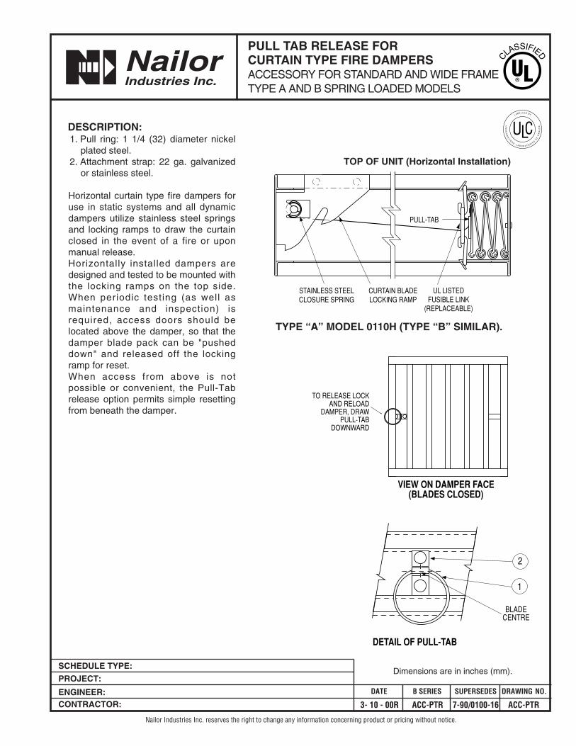
DESCRIPTION:1. Pull ring: 1 1/4 (32) diameter nickel
plated steel.2. Attachment strap: 22 ga. galvanized
or stainless steel.
Horizontal curtain type fire dampers foruse in static systems and all dynamicdampers utilize stainless steel springsand locking ramps to draw the curtainclosed in the event of a fire or uponmanual release. Horizontally installed dampers aredesigned and tested to be mounted withthe locking ramps on the top side.When periodic testing (as well asmaintenance and inspection) isrequired, access doors should belocated above the damper, so that thedamper blade pack can be "pusheddown" and released off the lockingramp for reset.When access from above is notpossible or convenient, the Pull-Tabrelease option permits simple resettingfrom beneath the damper.
STAINLESS STEELCLOSURE SPRING
CURTAIN BLADELOCKING RAMP
UL LISTEDFUSIBLE LINK
(REPLACEABLE)
PULL-TAB
VIEW ON DAMPER FACE(BLADES CLOSED)
TO RELEASE LOCKAND RELOAD
DAMPER, DRAWPULL-TAB
DOWNWARD
BLADECENTRE
1
2
TYPE “A” MODEL 0110H (TYPE “B” SIMILAR).
DETAIL OF PULL-TAB
TOP OF UNIT (Horizontal Installation)
Page 1 of 2Dimensions are in inches (mm).
SCHEDULE TYPE:
PROJECT:
ENGINEER:CONTRACTOR:
DATE B SERIES SUPERSEDES DRAWING NO.
"QUICK-SET" RETAINING ANGLESFOR ALL SLEEVED FIRE ANDCOMBINATION FIRE/SMOKE DAMPERSMODELS: QS1 AND QS2
Nailor Industries Inc. reserves the right to change any information concerning product or pricing without notice.
2 - 26 - 09 FD-ACC 6 - 5 - 03 QSRA
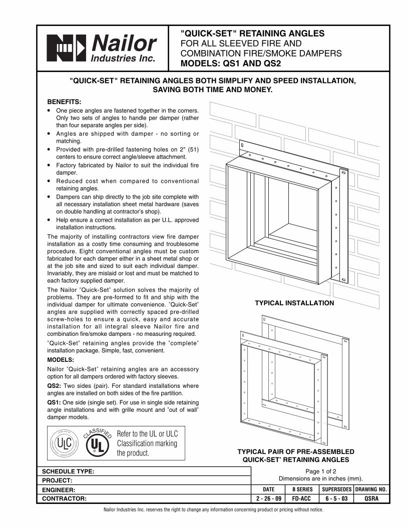
BENEFITS:• One piece angles are fastened together in the corners.
Only two sets of angles to handle per damper (ratherthan four separate angles per side).
• Angles are shipped with damper - no sorting ormatching.
• Provided with pre-drilled fastening holes on 2" (51)centers to ensure correct angle/sleeve attachment.
• Factory fabricated by Nailor to suit the individual firedamper.
• Reduced cost when compared to conventionalretaining angles.
• Dampers can ship directly to the job site complete withall necessary installation sheet metal hardware (saveson double handling at contractor’s shop).
• Help ensure a correct installation as per U.L. approvedinstallation instructions.
The majority of installing contractors view fire damperinstallation as a costly time consuming and troublesomeprocedure. Eight conventional angles must be customfabricated for each damper either in a sheet metal shop orat the job site and sized to suit each individual damper.Invariably, they are mislaid or lost and must be matched toeach factory supplied damper.
The Nailor "Quick-Set" solution solves the majority ofproblems. They are pre-formed to fit and ship with theindividual damper for ultimate convenience. "Quick-Set"angles are supplied with correctly spaced pre-drilledscrew-holes to ensure a quick, easy and accurateinstallation for al l integral sleeve Nailor f ire andcombination fire/smoke dampers - no measuring required.
"Quick-Set" retaining angles provide the "complete"installation package. Simple, fast, convenient.
MODELS:
Nailor "Quick-Set" retaining angles are an accessoryoption for all dampers ordered with factory sleeves.
QS2: Two sides (pair). For standard installations whereangles are installed on both sides of the fire partition.
QS1: One side (single set). For use in single side retainingangle installations and with grille mount and "out of wall"damper models.
TYPICAL PAIR OF PRE-ASSEMBLEDQUICK-SET’ RETAINING ANGLES
"QUICK-SET" RETAINING ANGLES BOTH SIMPLIFY AND SPEED INSTALLATION, SAVING BOTH TIME AND MONEY.
TYPICAL INSTALLATION
Refer to the UL or ULCClassification marking the product.
SCHEDULE TYPE:
PROJECT:
ENGINEER:CONTRACTOR:
DATE B SERIES SUPERSEDES DRAWING NO.
"QUICK-SET" RETAINING ANGLESFOR ALL SLEEVED FIRE ANDCOMBINATION FIRE/SMOKE DAMPERSMODELS: QS1 AND QS2
Nailor Industries Inc. reserves the right to change any information concerning product or pricing without notice.
Page 2 of 2Dimensions are in inches (mm).
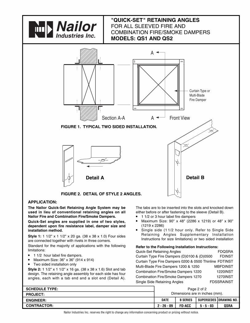
Section A-A Front ViewA
A
Curtain Type orMulti-BladeFire Damper
FIGURE 2. DETAIL OF STYLE 2 ANGLES.
The Nailor Quick-Set Retaining Angle System may beused in lieu of conventional retaining angles on allNailor Fire and Combination Fire/Smoke Dampers.Quick-Set angles are supplied in one of two styles,dependent upon fire resistance label, damper size andinstallation method.
Style 1: 1 1/2" x 1 1/2" x 20 ga. (38 x 38 x 1.0) Four sidesare connected together with rivets in three corners.Standard for the majority of applications with the followinglimitations:
• 1 1/2 hour label fire dampers.• Maximum Size: 36" x 36" (914 x 914)• Two sided installation onlyStyle 2: 1 1/2" x 1 1/2" x 16 ga. (38 x 38 x 1.6) Slot and tabdesign. The retaining angle assembly for each side has fourangles, each with a tab end and a slot end (Detail A).
The tabs are to be inserted into the slots and knocked downeither before or after fastening to the sleeve (Detail B).• 1 1/2 or 3 hour label fire dampers• Maximum Size: 90" x 48" (2286 x 1219) or 48" x 90"
(1219 x 2286)• Single side (1 1/2 hour only. Refer to Single Side
Retaining Angles Supplementary InstallationInstructions for size limitations) or two sided installation
Refer to the Following Installation Instructions:Quick-Set Retaining Angles FDQSRACurtain Type Fire Dampers (D)0100 & (D)0500 FDINSTCurtain Type Fire Dampers 0200 & 0500 Thinline FDTINSTMulti-Blade Fire Dampers 1200 & 1250 MBFDINSTCombination Fire/Smoke Dampers 1220 1220INSTCombination Fire/Smoke Dampers 1270 1270INSTSingle Side Retaining Angles FDSSRAINST
FIGURE 1. TYPICAL TWO SIDED INSTALLATION.
Detail A Detail B
APPLICATION:
2 - 26 - 09 FD-ACC 5 - 5 - 03 QSRA
SCHEDULE TYPE:
PROJECT:
ENGINEER:CONTRACTOR:
DATE B SERIES SUPERSEDES DRAWING NO.
25 - 10 - 00R FD 7-00/0100-14 STD-SL
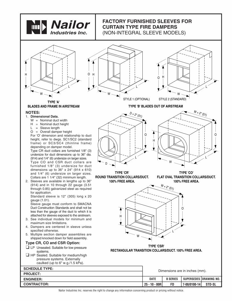
FACTORY FURNISHED SLEEVES FORCURTAIN TYPE FIRE DAMPERS(NON-INTEGRAL SLEEVE MODELS)
Nailor Industries Inc. reserves the right to change any information concerning product or pricing without notice.
Nailor Industries Inc.
Dimensions are in inches (mm).
TYPE 'A'BLADES AND FRAME IN AIRSTREAM TYPE 'B' BLADES OUT OF AIRSTREAM
TYPE 'CO'FLAT OVAL TRANSITION COLLARS/DUCT.
100% FREE AREA.
TYPE 'CR'ROUND TRANSITION COLLARS/DUCT.
100% FREE AREA.
W + 2" (51)
TYPE 'CSR'RECTANGULAR TRANSITION COLLARS/DUCT. 100% FREE AREA.
O
H
W + 2" (51)
W
O
D + 2" (51)
D
O
H
W
W
HO
W
HO
W
H
STYLE 2 (STANDARD)STYLE 1 (OPTIONAL)
L
L L
LLL
NOTES:1. Dimensional Data.
W = Nominal duct widthH = Nominal duct heightL = Sleeve lengthO = Overall damper heightFor ‘O’ dimension and relationship to ductheight, refer to dwgs. SC1/SC2 (standardframe) or SC3/SC4 (thinline frame)depending on damper model. Type CR duct collars are furnished 1/8" (3)undersize for duct dimensions up to 36" dia.(914) and 1/4" (6) undersize on larger sizes.Type CO and CSR duct collars arefurnished 1/8" (3) undersize for ductdimensions up to 36" x 24" (914 x 610)and 1/4" (6) undersize on larger sizes.Collars are 1 1/4" (32) minimum length.
2. Sleeves are available in lengths up to 36"(914) and in 10 through 22 gauge (3.51through 0.85) galvanized steel as requiredfor application.Standard sleeve is 12" (305) long x 20gauge (1.01).Sleeve gauge must conform to SMACNADuct Construction Standards and shall not beless than the gauge of the duct to which it isattached for sleeves exposed to the airstream.
3. See individual models for minimum andmaximum size limitations.
4. Dampers are centered in sleeve unlessspecified otherwise.
5. Multiple section damper assemblies areshipped knocked down for field assembly.
Type CR, CO and CSR Option:❑ LP Unsealed. Suitable for low pressure
systems.❑ HP Sealed. Suitable for medium/high
pressure systems. Externallycaulked (up to 6" w.g./1.5 kPa).
SCHEDULE TYPE:
PROJECT:
ENGINEER:CONTRACTOR:
DATE B SERIES SUPERSEDES DRAWING NO.
1 - 24 - 06 FD 2 - 25 - 02R SC1
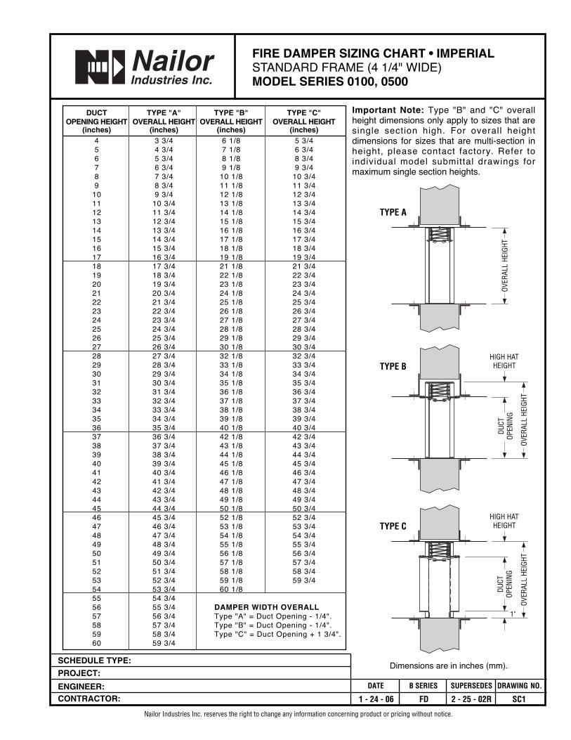
FIRE DAMPER SIZING CHART • IMPERIALSTANDARD FRAME (4 1/4" WIDE)MODEL SERIES 0100, 0500
Nailor Industries Inc. reserves the right to change any information concerning product or pricing without notice.
Dimensions are in inches (mm).
DUCT TYPE "A" TYPE "B" TYPE "C"OPENING HEIGHT OVERALL HEIGHT OVERALL HEIGHT OVERALL HEIGHT
(inches) (inches) (inches) (inches)4 3 3/4 6 1/8 5 3/45 4 3/4 7 1/8 6 3/46 5 3/4 8 1/8 8 3/47 6 3/4 9 1/8 9 3/48 7 3/4 10 1/8 10 3/49 8 3/4 11 1/8 11 3/4
10 9 3/4 12 1/8 12 3/411 10 3/4 13 1/8 13 3/412 11 3/4 14 1/8 14 3/413 12 3/4 15 1/8 15 3/414 13 3/4 16 1/8 16 3/415 14 3/4 17 1/8 17 3/416 15 3/4 18 1/8 18 3/417 16 3/4 19 1/8 19 3/418 17 3/4 21 1/8 21 3/419 18 3/4 22 1/8 22 3/420 19 3/4 23 1/8 23 3/421 20 3/4 24 1/8 24 3/422 21 3/4 25 1/8 25 3/423 22 3/4 26 1/8 26 3/424 23 3/4 27 1/8 27 3/425 24 3/4 28 1/8 28 3/426 25 3/4 29 1/8 29 3/427 26 3/4 30 1/8 30 3/428 27 3/4 32 1/8 32 3/429 28 3/4 33 1/8 33 3/430 29 3/4 34 1/8 34 3/431 30 3/4 35 1/8 35 3/432 31 3/4 36 1/8 36 3/433 32 3/4 37 1/8 37 3/434 33 3/4 38 1/8 38 3/435 34 3/4 39 1/8 39 3/436 35 3/4 40 1/8 40 3/437 36 3/4 42 1/8 42 3/438 37 3/4 43 1/8 43 3/439 38 3/4 44 1/8 44 3/440 39 3/4 45 1/8 45 3/441 40 3/4 46 1/8 46 3/442 41 3/4 47 1/8 47 3/443 42 3/4 48 1/8 48 3/444 43 3/4 49 1/8 49 3/445 44 3/4 50 1/8 50 3/446 45 3/4 52 1/8 52 3/447 46 3/4 53 1/8 53 3/448 47 3/4 54 1/8 54 3/449 48 3/4 55 1/8 55 3/450 49 3/4 56 1/8 56 3/451 50 3/4 57 1/8 57 3/452 51 3/4 58 1/8 58 3/453 52 3/4 59 1/8 59 3/454 53 3/4 60 1/855 54 3/456 55 3/4 DAMPER WIDTH OVERALL57 56 3/4 Type "A" = Duct Opening - 1/4".58 57 3/4 Type "B" = Duct Opening - 1/4".59 58 3/4 Type "C" = Duct Opening + 1 3/4".60 59 3/4
HIGH HATHEIGHT
OVER
ALL
HEIG
HT
DUCT
OPEN
ING
1"
TYPE C
OVER
ALL
HEIG
HT
TYPE A
HIGH HATHEIGHT
OVER
ALL
HEIG
HT
DUCT
OPEN
ING
TYPE B
Important Note: Type "B" and "C" overallheight dimensions only apply to sizes that aresingle section high. For overall heightdimensions for sizes that are multi-section inheight, please contact factory. Refer toindividual model submittal drawings formaximum single section heights.
SCHEDULE TYPE:
PROJECT:
ENGINEER:CONTRACTOR:
DATE B SERIES SUPERSEDES DRAWING NO.
1 - 24 - 06 FD 2 - 25 - 02R SC2
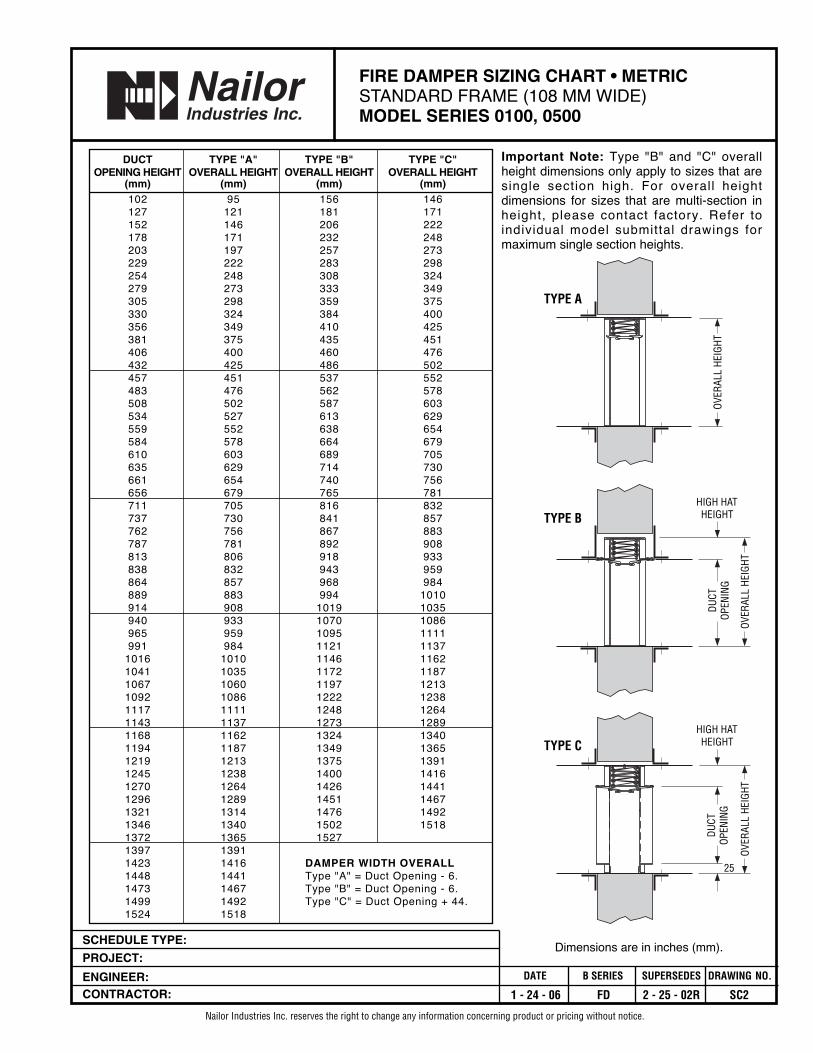
FIRE DAMPER SIZING CHART • METRICSTANDARD FRAME (108 MM WIDE)MODEL SERIES 0100, 0500
Nailor Industries Inc. reserves the right to change any information concerning product or pricing without notice.
Dimensions are in inches (mm).
DUCT TYPE "A" TYPE "B" TYPE "C"OPENING HEIGHT OVERALL HEIGHT OVERALL HEIGHT OVERALL HEIGHT
(mm) (mm) (mm) (mm)102 95 156 146127 121 181 171152 146 206 222178 171 232 248203 197 257 273229 222 283 298254 248 308 324279 273 333 349305 298 359 375330 324 384 400356 349 410 425381 375 435 451406 400 460 476432 425 486 502457 451 537 552483 476 562 578508 502 587 603534 527 613 629559 552 638 654584 578 664 679610 603 689 705635 629 714 730661 654 740 756656 679 765 781711 705 816 832737 730 841 857762 756 867 883787 781 892 908813 806 918 933838 832 943 959864 857 968 984889 883 994 1010914 908 1019 1035940 933 1070 1086965 959 1095 1111991 984 1121 1137
1016 1010 1146 11621041 1035 1172 11871067 1060 1197 12131092 1086 1222 12381117 1111 1248 12641143 1137 1273 12891168 1162 1324 13401194 1187 1349 13651219 1213 1375 13911245 1238 1400 14161270 1264 1426 14411296 1289 1451 14671321 1314 1476 14921346 1340 1502 15181372 1365 15271397 13911423 1416 DAMPER WIDTH OVERALL1448 1441 Type "A" = Duct Opening - 6.1473 1467 Type "B" = Duct Opening - 6.1499 1492 Type "C" = Duct Opening + 44.1524 1518
HIGH HATHEIGHT
OVER
ALL
HEIG
HT
DUCT
OPEN
ING
25
TYPE C
OVER
ALL
HEIG
HT
TYPE A
HIGH HATHEIGHT
OVER
ALL
HEIG
HT
DUCT
OPEN
ING
TYPE B
Important Note: Type "B" and "C" overallheight dimensions only apply to sizes that aresingle section high. For overall heightdimensions for sizes that are multi-section inheight, please contact factory. Refer toindividual model submittal drawings formaximum single section heights.
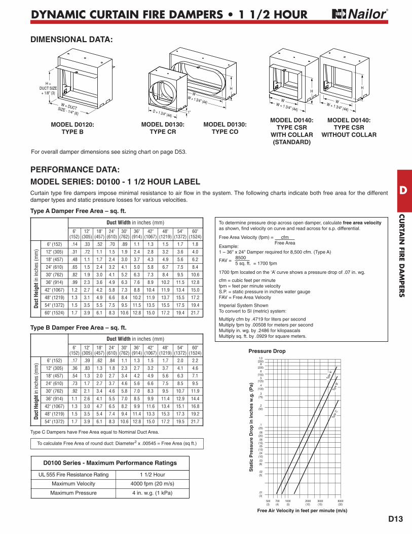
Type B Damper Free Area – sq. ft.
Type A Damper Free Area – sq. ft.
DYNAMIC CURTAIN FIRE DAMPERS • 1 1/2 HOUR
D13
CURTA
IN FIR
E DA
MPER
S
D
Duct Width in inches (mm)
6"(152)
12"(305)
18"(457)
24"(610)
30"(762)
36"(914)
42"(1067)
48"(1219)
54"(1372)
60"(1524)
Duct
Hei
ghtin inches (mm) 6" (152) .17 .39 .62 .84 1.1 1.3 1.5 1.7 2.0 2.2
12" (305) .36 .83 1.3 1.8 2.3 2.7 3.2 3.7 4.1 4.6
18" (457) .54 1.3 2.0 2.7 3.4 4.2 4.9 5.6 6.3 7.1
24" (610) .73 1.7 2.7 3.7 4.6 5.6 6.6 7.5 8.5 9.5
30" (762) .92 2.1 3.4 4.6 5.8 7.0 8.3 9.5 10.7 11.9
36" (914) 1.1 2.6 4.1 5.5 7.0 8.5 9.9 11.4 12.9 14.4
42" (1067) 1.3 3.0 4.7 6.5 8.2 9.9 11.6 13.4 15.1 16.8
48" (1219) 1.5 3.5 5.4 7.4 9.4 11.4 13.3 15.3 17.3 19.2
54" (1372) 1.7 3.9 6.1 8.3 10.6 12.8 15.0 17.2 19.5 21.7
Duct Width in inches (mm)
6"(152)
12"(305)
18"(457)
24"(610)
30"(762)
36"(914)
42"(1067)
48"(1219)
54"(1372)
60"(1524)
Duct
Hei
ghtin inches (mm)
6" (152) .14 .33 .52 .70 .89 1.1 1.3 1.5 1.7 1.8
12" (305) .31 .72 1.1 1.5 1.9 2.4 2.8 3.2 3.6 4.0
18" (457) .48 1.1 1.7 2.4 3.0 3.7 4.3 4.9 5.6 6.2
24" (610) .65 1.5 2.4 3.2 4.1 5.0 5.8 6.7 7.5 8.4
30" (762) .82 1.9 3.0 4.1 5.2 6.3 7.3 8.4 9.5 10.6
36" (914) .99 2.3 3.6 4.9 6.3 7.6 8.9 10.2 11.5 12.8
42" (1067) 1.2 2.7 4.2 5.8 7.3 8.8 10.4 11.9 13.4 15.0
48" (1219) 1.3 3.1 4.9 6.6 8.4 10.2 11.9 13.7 15.5 17.2
54" (1372) 1.5 3.5 5.5 7.5 9.5 11.5 13.5 15.5 17.5 19.4
60" (1524) 1.7 3.9 6.1 8.3 10.6 12.8 15.0 17.2 19.4 21.7
For overall damper dimensions see sizing chart on page D53.
MODEL D0120:TYPE B
MODEL D0130:TYPE CR
MODEL D0130:TYPE CO
MODEL D0140:TYPE CSR
WITH COLLAR(STANDARD)
MODEL D0140:TYPE CSR
WITHOUT COLLAR
H = DUCT SIZE
+ 1/8" (3)
W = DUCT �SIZE - 1/4" (6)
HH
W + 1 3/4" (44)
WW + 1 3/4" (44)
W
D + 1 3/4" (44)
D W + 1 3/4" (44)
WH
1"
700(4)
1000(5)
2000(10)
3000(15)
6000(30)
Free Air Velocity in feet per minute (m/s)
Pressure Drop
.01(3)
.2(50)
.02(5)
.03(8)
.1(25)
.04(10)
.08(20)
.05(13)
.06(15)
1.0(250)
.8(200)
.6
.5(150)
(125).4
(100)
.3(75)
Sta
tic
Pre
ssu
re D
rop
in in
ches
w.g
. (P
a)
500(3)
Type
‘A’
Type
‘B’
Type
‘C’
Type C Dampers have Free Area equal to Nominal Duct Area.
To calculate Free Area of round duct: Diameter2 x .00545 = Free Area (sq ft.)
DIMENSIONAL DATA:
PERFORMANCE DATA:
MODEL SERIES: D0100 - 1 1/2 HOUR LABELCurtain type fire dampers impose minimal resistance to air flow in the system. The following charts indicate both free area for the differentdamper types and static pressure losses for various velocities.
D0100 Series - Maximum Performance Ratings
UL 555 Fire Resistance Rating 1 1/2 Hour
Maximum Velocity 4000 fpm (20 m/s)
Maximum Pressure 4 in. w.g. (1 kPa)
To determine pressure drop across open damper, calculate free area velocityas shown, find velocity on curve and read across for s.p. differential.
Free Area Velocity (fpm) = cfmFree Area
Example: 1 – 36" x 24" Damper required for 8,500 cfm. (Type A)
FAV = 8500 5 sq. ft. = 1700 fpm
1700 fpm located on the ‘A’ curve shows a pressure drop of .07 in. wg.
cfm = cubic feet per minutefpm = feet per minute velocityS.P. = static pressure in inches water gaugeFAV = Free Area Velocity
Imperial System ShownTo convert to SI (metric) system:
Multiply cfm by .4719 for liters per second Multiply fpm by .00508 for meters per second Multiply in. wg. by .2486 for kilopascals Multiply sq. ft. by .0929 for square meters.

Nailor Industries Inc. reserves the right to change any information concerning product or specification without notice or obligation.
Page 1.0803/16 IOM-FDIMP
OPERATION AND MAINTENANCE PROCEDURESCURTAIN TYPE FIRE DAMPERSMODEL SERIES: (D)0100, 0200, 0300 AND (D)0500
Page 1 of 2
Dampers are an essential part of the fire protection system in a building. The NFPA recommends that fire dampers betested periodically to verify the operational abilities of each installed damper. See NFPA 80, Standard for Fire Doors andOther Opening Protectives, for Operational Test and Periodic Inspection and Testing details.CAUTION:Some curtain fire dampers utilize high torque springs under tension; ensure HVAC fans are turned off. Testing springassisted fire dampers under airflow conditions is NOT RECOMMENDED and may severely damage or destroy ductwork.Use protective eyewear or safety glasses. Keep hands out of the blade path, as this can cause serious injury. Keep anyhard objects or tools out of the blade path as they can damage the blades when closing.
Periodic Inspection, Testing and MaintenanceConsult your local building code to verify whether there is a required maintenance and testing schedule. Most localjurisdictions reference NFPA 80 for Fire Dampers. Per NFPA 80, each damper should be tested and inspected 1 year afterinstallation and then every 4 years, except for hospitals, where the frequency is every 6 years.
1. Remove any obstructions, dirt, rust, corrosion, or other observed conditions that could impede proper damper operation.
2. Check closure springs (if applicable). If damaged or defective, repair or replace.
3a. Non-Spring Assisted DampersBend metal straps away from damper frame so that they are straight. Removefusible link and allow the blade package to drop and close naturally by the forceof gravity. See Detail 1. Use caution, keeping fingers, hands, arms and tools outof the blade path.
3b. Dynamic Rated or Spring Assisted DampersAS SOON AS THE LINK HAS BEEN REMOVED, THE SPRING WILL FORCE THEBLADES TO CLOSE INSTANTANEOUSLY. THE BLADE PATH MUST BE KEPTCLEAR.
4. Ensure the damper closes completely, without assistance. If the damper designincorporates a locking ramp to hold the damper in the fully closed position,confirm that the ramp locks properly.
5. Clean damper blades and other moving parts if necessary. Use of a mild detergent or solvents is recommended forany cleaning required. Lubricate moving parts with a dry lubricant (such as T.F.E. Dry Lube). Never use a regularlubricating oil on dampers, as it will attract dirt and grit.
6. Lift the blade package to the top of the damper to reopen and replace the fusible link. Take care not to rack, deformor damage the blades when reopening.
Reopening spring assisted fire dampers may be extremely difficult and in some cases, impossible.If it is determined that the damper is impossible or impractical to test or reopen, a thorough examination of the blade pathis required to ensure that nothing will prevent the damper from closing. Common obstructions include: racked damperframes, retaining angle installation screws, construction debris and contaminants.
7. Slide the replacement fusible link onto the metal straps. When replacing the fusible link, make sure it is the sametemperature rating of the link you are replacing. If a different temperature, contact factory. Install fusible link so thatthe temperature rating is facing outward and is visible.
8. Bend the metal straps up to hold the fusible link in place.
Detail 1
Page"Comp l e t e A i r C o n t r o l a n d D i s t r i b u t i o n S o l u t i o n s . " www . n a i l o r . c om
Calgary, CanadaTel: 403-279-8619Fax: 403-279-5035
Houston, TexasTel: 281-590-1172Fax: 281-590-3086
Toronto, CanadaTel: 416-744-3300Fax: 416-744-3360
Las Vegas, NevadaTel: 702-648-5400Fax: 702-638-0400
"Comp l e t e A i r C o n t r o l a n d D i s t r i b u t i o n S o l u t i o n s . "Page 1.081 3/16 IOM-FDIMP
Page 2 of 2
Receiving, Storage, PreparationUpon delivery, inspect shipping containers and contents closely. Note any damages on freight carrier’s delivery receipt.Store dampers in a cool, dry and safe location in an orderly manner away from construction site, warehouse traffic, othermaterials, etc. Cover with plastic sheeting to protect from excessive moisture, dirt and debris.Inspect dampers prior to installation. Dampers must be cleaned per procedures outlined in this document prior toinstallation if dirt, rust or corrosion is observed.
Page 1.0501/14 IOM-FDINST
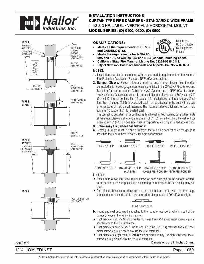
INSTALLATION INSTRUCTIONSCURTAIN TYPE FIRE DAMPERS • STANDARD & WIDE FRAME1 1/2 & 3 HR. LABEL • VERTICAL & HORIZONTAL MOUNTMODEL SERIES: (D) 0100, 0300, (D) 0500
Nailor Industries Inc. reserves the right to change any information concerning product or specification without notice or obligation.
Page 1 of 4 Dimensions are in inches (mm).
WALL
SLEEVE(SEE NOTE 2)
RETAININGANGLES RETAINING
ANGLESSHOWNREVERSED(SEE NOTE 5)
OPTI
ONAL
ACCE
SS D
OOR
EXPANSIONCLEARANCE
6" or 16"SEE NOTE 2.
TYPE A
DUCTCONNECTION(SEE NOTE 3)
DUCT CONNECTION(SEE NOTE 3)
TYPE C
DUCTCONNECTION(SEE NOTE 3)
EXPANSIONCLEARANCE(SEE NOTE 6)
TYPE BSTYLE 2
1" (25) MINIMUM(SEE NOTE 5)
SLEEVE(SEE NOTE 2)
TYPE BSTYLE 1
PLAIN "S" SLIP HEMMED "S" SLIP DOUBLE "S" SLIP
STANDING "S" SLIP(ALT. BAR)
INSIDE SLIP JOINT
STANDING "S" SLIP(ANGLE REINFORCED)
STANDING "S" SLIP(BAR REINFORCED)
STANDING "S" SLIP
FLAT DRIVE SLIP
b. Round and oval duct may be attached to the round or oval collar which is part of thedamper/sleeve in the following manner:
• Duct diameters 22" (559) and smaller must use three #10 sheet metal screws equallyspaced around the circumference.
• Duct diameters over 22" (559) up to and including 36" (914) may use five #10 sheetmetal screws equally spaced around the circumference.
• Duct diameters larger than 36" (914) wide or diameter may use eight #10 sheet metalscrews equally spaced around the circumference.
In addition:• A maximum of two #10 sheet metal screws on each side and on the bottom, located
in the center of the slip pocket and penetrating both sides of the slip pocket may beused.
• One of the above connections on the top and bottom joints with flat drive slipconnections on the side joints may be used for dampers up to 20" (508) in height.
Refer to theUL ClassificationMarking on theProduct
QUALIFICATIONS:• Meets all the requirements of UL 555
and CAN/ULC-S112.• Meets the requirements for NFPA 80,
90A and 101, as well as IBC and NBC (Canada) building codes.• California State Fire Marshal Listing No. 03225-0935:0113.• City of New York Board of Standards and Appeals. Cal. No. 460-88-SA.
NOTES:1. Installation shall be in accordance with the appropriate requirements of the National
Fire Protection Association Standard NFPA 90A latest edition.2. Damper Sleeve: Sleeve thickness must be equal to or thicker than the duct
connected to it. Sleeve gauge requirements are listed in the SMACNA Fire, Smoke andRadiation Damper Installation Guide for HVAC Systems and in NFPA 90A. If a break-away style duct/sleeve connection is not used, damper sleeves up to 36" wide by 24"(914 x 610) high of not less than 16 gauge (1.61) coated steel, or larger sleeves of notless than 14 gauge (1.99) thick coated steel may be attached to the duct with screwsor other types of mechanical fasteners. The maximum sleeve thickness for such rigidjoints is 10 gauge (3.51) for coated steel.The connecting duct shall not be continuous thru the wall or floor opening but shall terminateat the sleeve. Sleeves shall extend a maximum of 6" (152) on either side of the wall or flooropening or 16" (406) on one side when incorporating a factory installed access door.
3. Break-away duct/sleeve connections: a. Rectangular ducts must use one or more of the following connections if the gauge is
less than the requirement in note 2 for rigid connections:
Page 1.051 1/14 IOM-FDINST
Nailor Industries Inc. reserves the right to change any information concerning product or specification without notice or obligation.
Page 2 of 4Dimensions are in inches (mm).
Note: When optional sealing of these break-away connections is desired, the duct sealant shall be PA2084T Duct Sealant by Precision or waterbased DP1010 by Design Polymetrics.c. For the use of approved alternative Ductmate or TDC/TDF break-away connections, refer to the supplements noted on page 4.4. Damper/sleeve attachment: Damper shall be secured to sleeve with 1/4" (6) long welds, spot welds, 3/16" (4.76) steel rivets, 1/4" (6.35)
dia. bolts and nuts, #8 sheet metal screws, or 3/16" (4.76) dia. buttonloks on both sides at 6" (152) on center and a maximum of 2" (51) fromthe corners of the damper on all four sides. For field assembled sleeves, the inner dimensions of the sleeve shall be equal to the outer dimensionsof the damper.
5. Retaining angles shall be a minimum of 1 1/2" x 1 1/2" x 16 gauge (38 x 38 x 1.61) for dampers up to 90" (2286)in width and up to 90"(2286) in height. For dampers exceeding these dimensions, the angles shall be a minimum of 2" x 2" x 10 gauge (51 x 51 x 3.51). Securethe retaining angles to the sleeve with 1/2" (12.7) long welds, 1/4" (6.35) dia. bolts and nuts, 3/16" (4.76) dia. steel rivets or #8 sheet metalscrews 8" (203) on center and 2" (51) maximum from corner of sleeve on all four sides. The retaining angles must lap the structural openingby 1" (25.4) minimum. When the ductwork terminates at the wall or floor, the retaining angles may be turned inwards, providing the openingsize is increased by an amount equal to twice the combined thickness of the angle and the height of the screw or bolthead to maintain therequired expansion clearance. Field fabricated retaining angles are not to be mechanically fastened at the corners.
6. Expansion clearance between the sleeve and wall or floor shall be a minimum of 1/8" per foot (3.18 per 305) of width or height of the sleeve.The maximum size of the opening shall be 2" (50.8) larger in either dimension than the allowable minimum size. For example; a sleeve dimensionof 36" x 36" (914 x 914) shall have an opening size of 36 3/8" x 36 3/8" (924 x 924) minimum and 38 3/8" x 38 3/8" (975 x 975) maximum.
7. The maximum Type A fire damper sizes are as follows:
Model Series Single Section Multiple Section0100 Static Vertical (1 1/2 hr. label) 60" x 60" (1524 x 1524) 120" x 120" (3048 x 3048)
Horizontal (1 1/2 hr. label) 60" x 60" (1524 x 1524) 102" x 60" (2591 x 1524)0300 Static Vertical (1 1/2 hr. label) 60" x 48" (1524 x 1219) –
Horizontal (1 1/2 hr. label) 48" x 48" (1219 x 1219) –D0100 Dynamic Vertical (1 1/2 hr. label) 36" x 36" (914 x 914) 36" x 48" (914 x 1219) OR
72" x 24" (1829 x 610)Horizontal (1 1/2 hr. label) 24" x 24" (610 x 610) –
0500 Static Vertical (3 hr. label) 48" x 48" (1219 x 1219) 108" x 72" (2743 x 1829)Horizontal (3 hr. label) 36" x 36" (914 x 914) 72" x 36" (1829 x 914)
0540 Static Vertical (3 hr. label) 60" x 48" (1524 x 1219) or –24" x 60" (610 x 1524)
D0500 Dynamic Vertical (3 hr. label) 36" x 36" (914 x 914) 36" x 48" (914 x 1219) OR72" x 24" (1829 x 610)
Horizontal (3 hr. label) 24" x 24" (610 x 610) –
Type B and C dampers have the same overall damper size but the connecting ducts are smaller due to the B or C enclosures. See Type B and Type C specification drawings for maximum duct sizes.Maximum individual sections not to exceed 34" x 60" (864 x 1524).Maximum individual sections not to exceed 36" x 36" (914 x 914).Maximum individual sections not to exceed 24" x 24" (610 x 610), up to 48" x 24" (1219 x 610). Assemblies larger than 48" x 24" (1219 x 610) will be made up of individual sections not to exceed 18" x 24" (457 x 610).
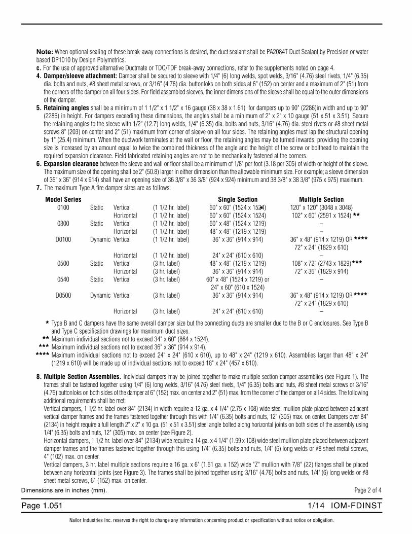
8. Multiple Section Assemblies. Individual dampers may be joined together to make multiple section damper assemblies (see Figure 1). Theframes shall be fastened together using 1/4" (6) long welds, 3/16" (4.76) steel rivets, 1/4" (6.35) bolts and nuts, #8 sheet metal screws or 3/16"(4.76) buttonloks on both sides of the damper at 6" (152) max. on center and 2" (51) max. from the corner of the damper on all 4 sides. The followingadditional requirements shall be met: Vertical dampers, 1 1/2 hr. label over 84" (2134) in width require a 12 ga. x 4 1/4" (2.75 x 10⁸) wide steel mullion plate placed between adjacentvertical damper frames and the frames fastened together through this with 1/4" (6.35) bolts and nuts, 12" (305) max. on center. Dampers over 84"(2134) in height require a full length 2" x 2" x 10 ga. (51 x 51 x 3.51) steel angle bolted along horizontal joints on both sides of the assembly using1/4" (6.35) bolts and nuts, 12" (305) max. on center (see Figure 2).Horizontal dampers, 1 1/2 hr. label over 84" (2134) wide require a 14 ga. x 4 1/4" (1.99 x 10⁸) wide steel mullion plate placed between adjacentdamper frames and the frames fastened together through this using 1/4" (6.35) bolts and nuts, 1/4" (6) long welds or #8 sheet metal screws,4" (102) max. on center.Vertical dampers, 3 hr. label multiple sections require a 16 ga. x 6" (1.61 ga. x 152) wide "Z" mullion with 7/8" (22) flanges shall be placedbetween any horizontal joints (see Figure 3). The frames shall be joined together using 3/16" (4.76) bolts and nuts, 1/4" (6) long welds or #8sheet metal screws, 6" (152) max. on center.
**
*
***
***
***
****
****
****
Page 1.0521/14 IOM-FDINST
Nailor Industries Inc. reserves the right to change any information concerning product or specification without notice or obligation.
Page 3 of 4 Dimensions are in inches (mm).
TWOSTEEL
ANGLES
MULLIONPLATE
2" (51) MAX.
6" (152) MAX.
2" (51)
MAX.
2"(51)
MAX.
6"(152)
MAX.
6"(152)
MAX.
Figure 1.Fastening of damper frames (see note 8).
Figure 2.1 1/2 hr. label vertical installation over 84" x 84" (2134 x 2134) (see note 8).
"Z"MULLION
Figure 3.3 hr. label vertical installation multiple section (see note 8).
Page 1.053 1/14 IOM-FDINST
" C o m p l e t e A i r C o n t r o l a n d D i s t r i b u t i o n S o l u t i o n s . " w w w . n a i l o r . c o m
Page 4 of 4Dimensions are in inches (mm).
Calgary, CanadaTel: 403-279-8619Fax: 403-279-5035
Houston, TexasTel: 281-590-1172Fax: 281-590-3086
Toronto, CanadaTel: 416-744-3300Fax: 416-744-3360
Las Vegas, NevadaTel: 702-648-5400Fax: 702-638-0400
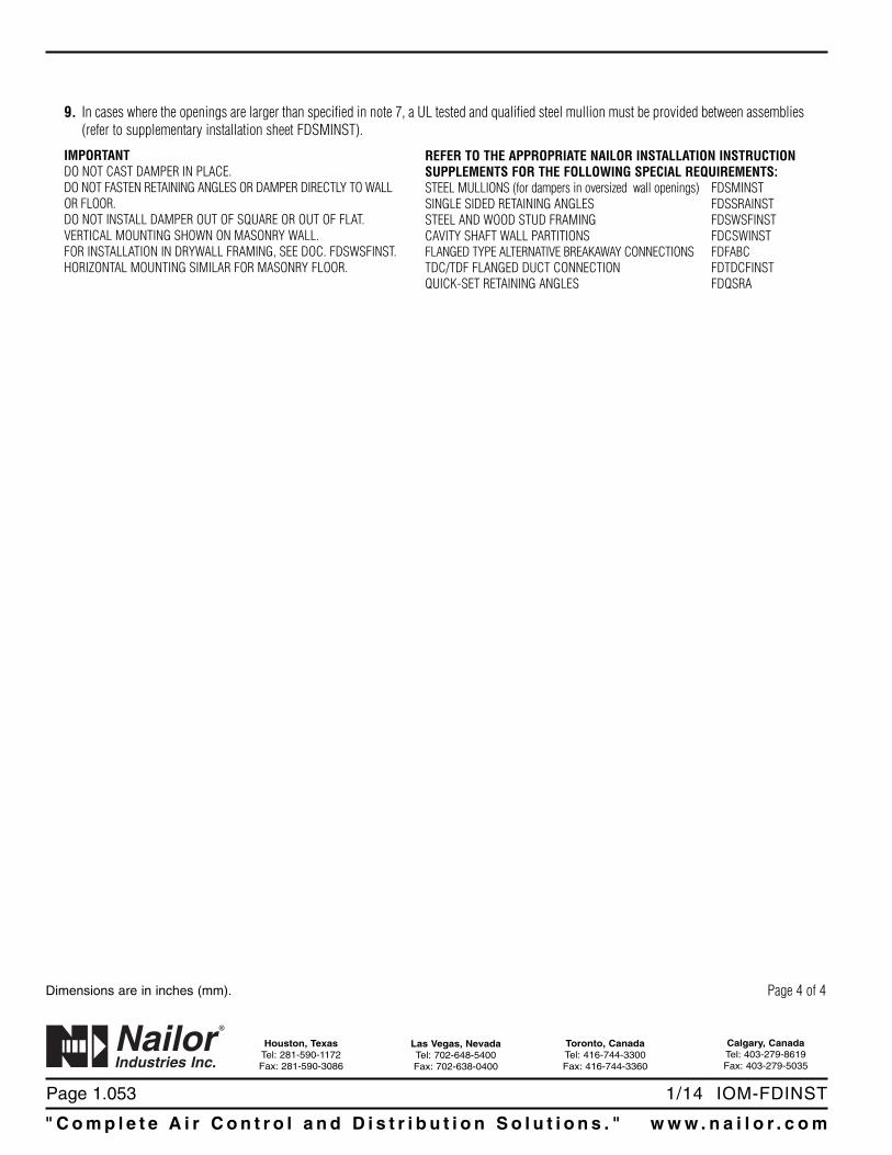
9. In cases where the openings are larger than specified in note 7, a UL tested and qualified steel mullion must be provided between assemblies(refer to supplementary installation sheet FDSMINST).
IMPORTANTDO NOT CAST DAMPER IN PLACE.DO NOT FASTEN RETAINING ANGLES OR DAMPER DIRECTLY TO WALL OR FLOOR.DO NOT INSTALL DAMPER OUT OF SQUARE OR OUT OF FLAT.VERTICAL MOUNTING SHOWN ON MASONRY WALL.FOR INSTALLATION IN DRYWALL FRAMING, SEE DOC. FDSWSFINST.HORIZONTAL MOUNTING SIMILAR FOR MASONRY FLOOR.
REFER TO THE APPROPRIATE NAILOR INSTALLATION INSTRUCTIONSUPPLEMENTS FOR THE FOLLOWING SPECIAL REQUIREMENTS:STEEL MULLIONS (for dampers in oversized wall openings) FDSMINSTSINGLE SIDED RETAINING ANGLES FDSSRAINSTSTEEL AND WOOD STUD FRAMING FDSWSFINSTCAVITY SHAFT WALL PARTITIONS FDCSWINSTFLANGED TYPE ALTERNATIVE BREAKAWAY CONNECTIONS FDFABCTDC/TDF FLANGED DUCT CONNECTION FDTDCFINSTQUICK-SET RETAINING ANGLES FDQSRA

Page 1.0305/02 IOM-FDSC
FIRE DAMPER SIZING CHART • IMPERIALSTANDARD FRAME (4 1/4" WIDE)MODEL SERIES 0100, 0500
Nailor Industries Inc. reserves the right to change any information concerning product or specification without notice or obligation.
HIGH HATHEIGHT
OVER
ALL
HEIG
HT
DUCT
OPEN
ING
1"
TYPE C
OVER
ALL
HEIG
HT
TYPE A
HIGH HATHEIGHT
OVER
ALL
HEIG
HT
DUCT
OPEN
ING
TYPE B
DUCT TYPE "A" TYPE "B" TYPE "C"OPENING HEIGHT OVERALL HEIGHT OVERALL HEIGHT OVERALL HEIGHT
(inches) (inches) (inches) (inches)4 3 3/4 6 1/8 5 3/45 4 3/4 7 1/8 6 3/46 5 3/4 8 1/8 8 3/47 6 3/4 9 1/8 9 3/48 7 3/4 10 1/8 10 3/49 8 3/4 11 1/8 11 3/4
10 9 3/4 12 1/8 12 3/411 10 3/4 13 1/8 13 3/412 11 3/4 14 1/8 14 3/413 12 3/4 15 1/8 15 3/414 13 3/4 16 1/8 16 3/415 14 3/4 17 1/8 17 3/416 15 3/4 18 1/8 18 3/417 16 3/4 19 1/8 19 3/418 17 3/4 21 1/8 21 3/419 18 3/4 22 1/8 22 3/420 19 3/4 23 1/8 23 3/421 20 3/4 24 1/8 24 3/422 21 3/4 25 1/8 25 3/423 22 3/4 26 1/8 26 3/424 23 3/4 27 1/8 27 3/425 24 3/4 28 1/8 28 3/426 25 3/4 29 1/8 29 3/427 26 3/4 30 1/8 30 3/428 27 3/4 32 1/8 32 3/429 28 3/4 33 1/8 33 3/430 29 3/4 34 1/8 34 3/431 30 3/4 35 1/8 35 3/432 31 3/4 36 1/8 36 3/433 32 3/4 37 1/8 37 3/434 33 3/4 38 1/8 38 3/435 34 3/4 39 1/8 39 3/436 35 3/4 40 1/8 40 3/437 36 3/4 42 1/8 42 3/438 37 3/4 43 1/8 43 3/439 38 3/4 44 1/8 44 3/440 39 3/4 45 1/8 45 3/441 40 3/4 46 1/8 46 3/442 41 3/4 47 1/8 47 3/443 42 3/4 48 1/8 48 3/444 43 3/4 49 1/8 49 3/445 44 3/4 50 1/8 50 3/446 45 3/4 52 1/8 52 3/447 46 3/4 53 1/8 53 3/448 47 3/4 54 1/8 54 3/449 48 3/4 55 1/8 55 3/450 49 3/4 56 1/8 56 3/451 50 3/4 57 1/8 57 3/452 51 3/4 58 1/8 58 3/453 52 3/4 59 1/8 59 3/454 53 3/4 60 1/855 54 3/456 55 3/4 DAMPER WIDTH OVERALL57 56 3/4 Type "A" = Duct Opening - 1/4".58 57 3/4 Type "B" = Duct Opening - 1/4".59 58 3/4 Type "C" = Duct Opening + 1 3/4".60 59 3/4
Dimensions are in inches (mm).

Page 1.031 5/02 IOM-FDSC
" C o m p l e t e A i r C o n t r o l a n d D i s t r i b u t i o n S o l u t i o n s . " w w w . n a i l o r . c o m
Calgary, CanadaTel: 403-279-8619Fax: 403-279-5035
Ft. Lauderdale, FloridaTel: 954-351-2444Fax: 954-351-2440
Houston, TexasTel: 281-590-1172Fax: 281-590-3086
Toronto, CanadaTel: 416-744-3300Fax: 416-744-3360
Page 1.0105/02 IOM-FDSTDSL
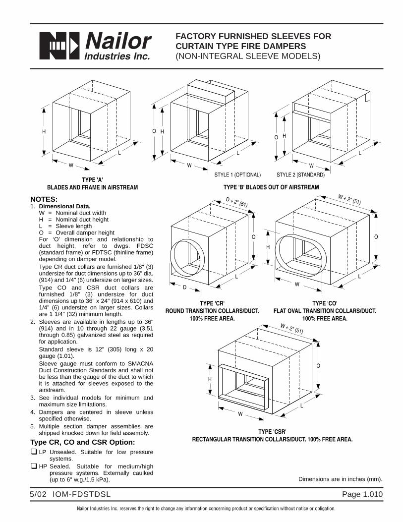
FACTORY FURNISHED SLEEVES FORCURTAIN TYPE FIRE DAMPERS(NON-INTEGRAL SLEEVE MODELS)
Nailor Industries Inc. reserves the right to change any information concerning product or specification without notice or obligation.
Dimensions are in inches (mm).
TYPE 'A'BLADES AND FRAME IN AIRSTREAM TYPE 'B' BLADES OUT OF AIRSTREAM
TYPE 'CO'FLAT OVAL TRANSITION COLLARS/DUCT.
100% FREE AREA.
TYPE 'CR'ROUND TRANSITION COLLARS/DUCT.
100% FREE AREA.
W + 2" (51)
TYPE 'CSR'RECTANGULAR TRANSITION COLLARS/DUCT. 100% FREE AREA.
O
H
W + 2" (51)
W
O
D + 2" (51)
D
O
H
W
W
HO
W
HO
W
H
STYLE 2 (STANDARD)STYLE 1 (OPTIONAL)
L
L L
LLL
NOTES:1. Dimensional Data.
W = Nominal duct widthH = Nominal duct heightL = Sleeve lengthO = Overall damper heightFor ‘O’ dimension and relationship to duct height, refer to dwgs. FDSC (standard frame) or FDTSC (thinline frame)depending on damper model. Type CR duct collars are furnished 1/8" (3)undersize for duct dimensions up to 36" dia.(914) and 1/4" (6) undersize on larger sizes.Type CO and CSR duct collars arefurnished 1/8" (3) undersize for ductdimensions up to 36" x 24" (914 x 610) and1/4" (6) undersize on larger sizes. Collarsare 1 1/4" (32) minimum length.
2. Sleeves are available in lengths up to 36"(914) and in 10 through 22 gauge (3.51through 0.85) galvanized steel as requiredfor application.Standard sleeve is 12" (305) long x 20gauge (1.01).Sleeve gauge must conform to SMACNADuct Construction Standards and shall notbe less than the gauge of the duct to whichit is attached for sleeves exposed to theairstream.
3. See individual models for minimum andmaximum size limitations.
4. Dampers are centered in sleeve unlessspecified otherwise.
5. Multiple section damper assemblies areshipped knocked down for field assembly.
Type CR, CO and CSR Option:❑ LP Unsealed. Suitable for low pressure
systems.❑ HP Sealed. Suitable for medium/high
pressure systems. Externally caulked(up to 6" w.g./1.5 kPa).

Page 1.011 5/02 IOM-FDSTDSL
" C o m p l e t e A i r C o n t r o l a n d D i s t r i b u t i o n S o l u t i o n s . " w w w . n a i l o r . c o m
Calgary, CanadaTel: 403-279-8619Fax: 403-279-5035
Ft. Lauderdale, FloridaTel: 954-351-2444Fax: 954-351-2440
Houston, TexasTel: 281-590-1172Fax: 281-590-3086
Toronto, CanadaTel: 416-744-3300Fax: 416-744-3360
Nailor Industries Inc. reserves the right to change any information concerning product or specification without notice or obligation.
Page 3.0902/05 IOM-FDCFSDINST
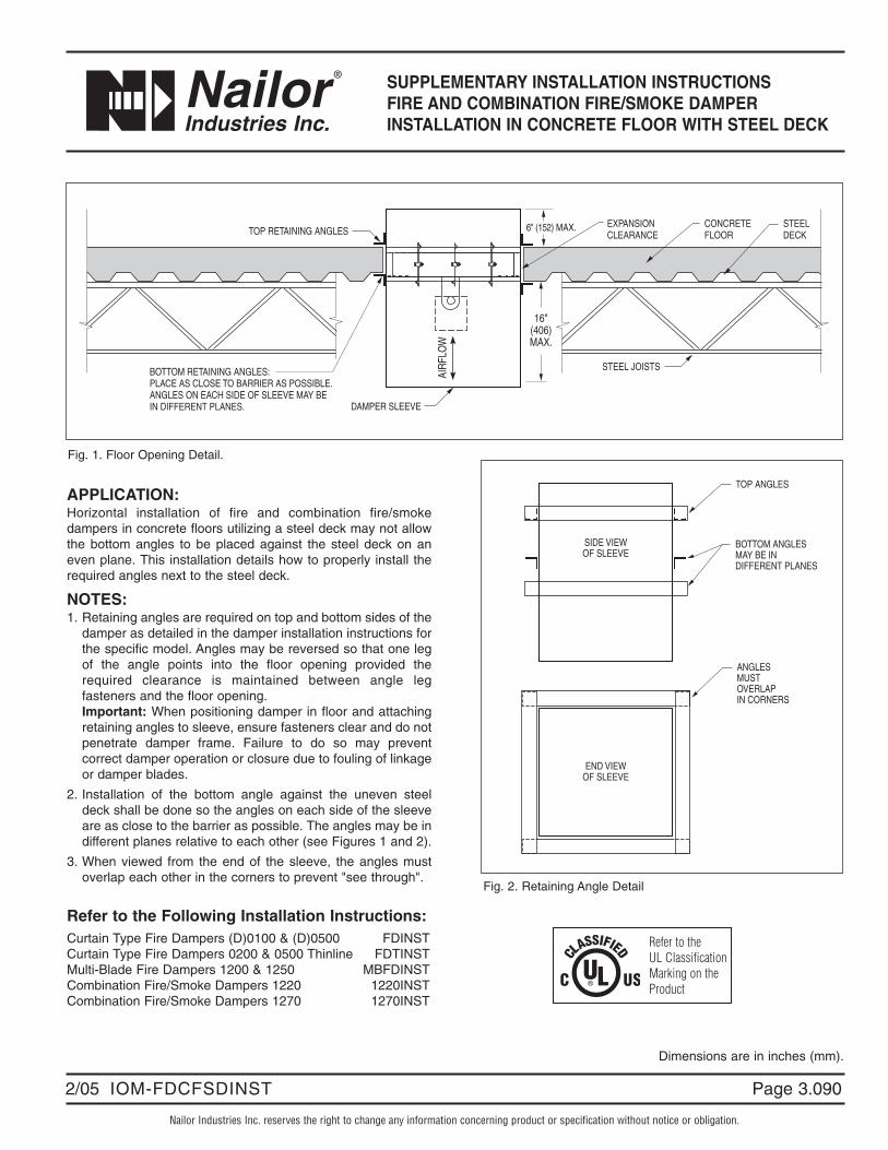
SUPPLEMENTARY INSTALLATION INSTRUCTIONSFIRE AND COMBINATION FIRE/SMOKE DAMPERINSTALLATION IN CONCRETE FLOOR WITH STEEL DECK
APPLICATION:Horizontal installation of fire and combination fire/smokedampers in concrete floors utilizing a steel deck may not allowthe bottom angles to be placed against the steel deck on aneven plane. This installation details how to properly install therequired angles next to the steel deck.
NOTES:1. Retaining angles are required on top and bottom sides of the
damper as detailed in the damper installation instructions forthe specific model. Angles may be reversed so that one legof the angle points into the floor opening provided therequired clearance is maintained between angle legfasteners and the floor opening.Important: When positioning damper in floor and attachingretaining angles to sleeve, ensure fasteners clear and do notpenetrate damper frame. Failure to do so may preventcorrect damper operation or closure due to fouling of linkageor damper blades.
2. Installation of the bottom angle against the uneven steeldeck shall be done so the angles on each side of the sleeveare as close to the barrier as possible. The angles may be indifferent planes relative to each other (see Figures 1 and 2).
3. When viewed from the end of the sleeve, the angles mustoverlap each other in the corners to prevent "see through".
Refer to the Following Installation Instructions:Curtain Type Fire Dampers (D)0100 & (D)0500 FDINSTCurtain Type Fire Dampers 0200 & 0500 Thinline FDTINSTMulti-Blade Fire Dampers 1200 & 1250 MBFDINSTCombination Fire/Smoke Dampers 1220 1220INSTCombination Fire/Smoke Dampers 1270 1270INST
6" (152) MAX.
16"(406)MAX.
STEEL JOISTS
TOP RETAINING ANGLES
BOTTOM RETAINING ANGLES:PLACE AS CLOSE TO BARRIER AS POSSIBLE.ANGLES ON EACH SIDE OF SLEEVE MAY BEIN DIFFERENT PLANES. DAMPER SLEEVE
AIR
FLO
W
CONCRETEFLOOR
EXPANSIONCLEARANCE
STEELDECK
Fig. 1. Floor Opening Detail.
TOP ANGLES
ANGLESMUSTOVERLAPIN CORNERS
BOTTOM ANGLESMAY BE INDIFFERENT PLANES
SIDE VIEWOF SLEEVE
END VIEWOF SLEEVE
Fig. 2. Retaining Angle Detail
Dimensions are in inches (mm).
Refer to theUL ClassificationMarking on theProduct

Page
" C o m p l e t e A i r C o n t r o l a n d D i s t r i b u t i o n S o l u t i o n s . " w w w . n a i l o r . c o m
Calgary, CanadaTel: 403-279-8619Fax: 403-279-5035
Houston, TexasTel: 281-590-1172Fax: 281-590-3086
Toronto, CanadaTel: 416-744-3300Fax: 416-744-3360
Las Vegas, NevadaTel: 702-648-5400Fax: 702-638-0400
Page 3.091 2/05 IOM-FDCFSDINST
" C o m p l e t e A i r C o n t r o l a n d D i s t r i b u t i o n S o l u t i o n s . "
Nailor Industries Inc. reserves the right to change any information concerning product or specification without notice or obligation.
Page 3.0408/07 IOM-FDCSWINST
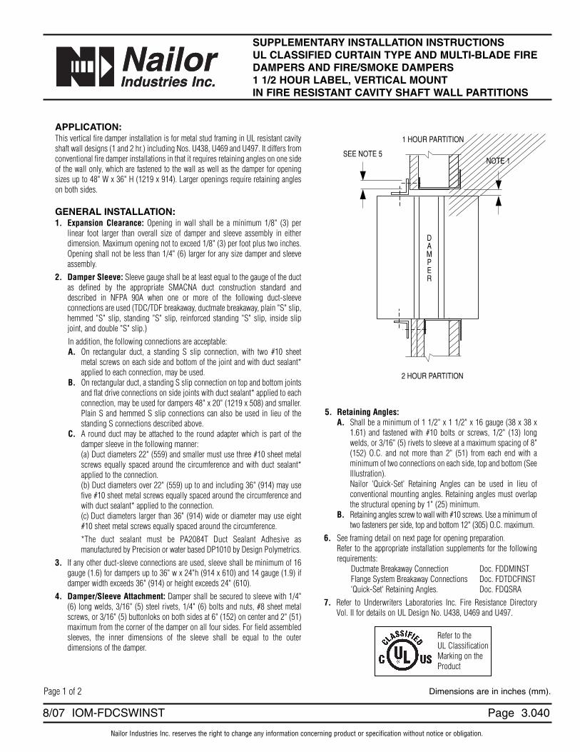
SUPPLEMENTARY INSTALLATION INSTRUCTIONSUL CLASSIFIED CURTAIN TYPE AND MULTI-BLADE FIREDAMPERS AND FIRE/SMOKE DAMPERS 1 1/2 HOUR LABEL, VERTICAL MOUNT IN FIRE RESISTANT CAVITY SHAFT WALL PARTITIONS
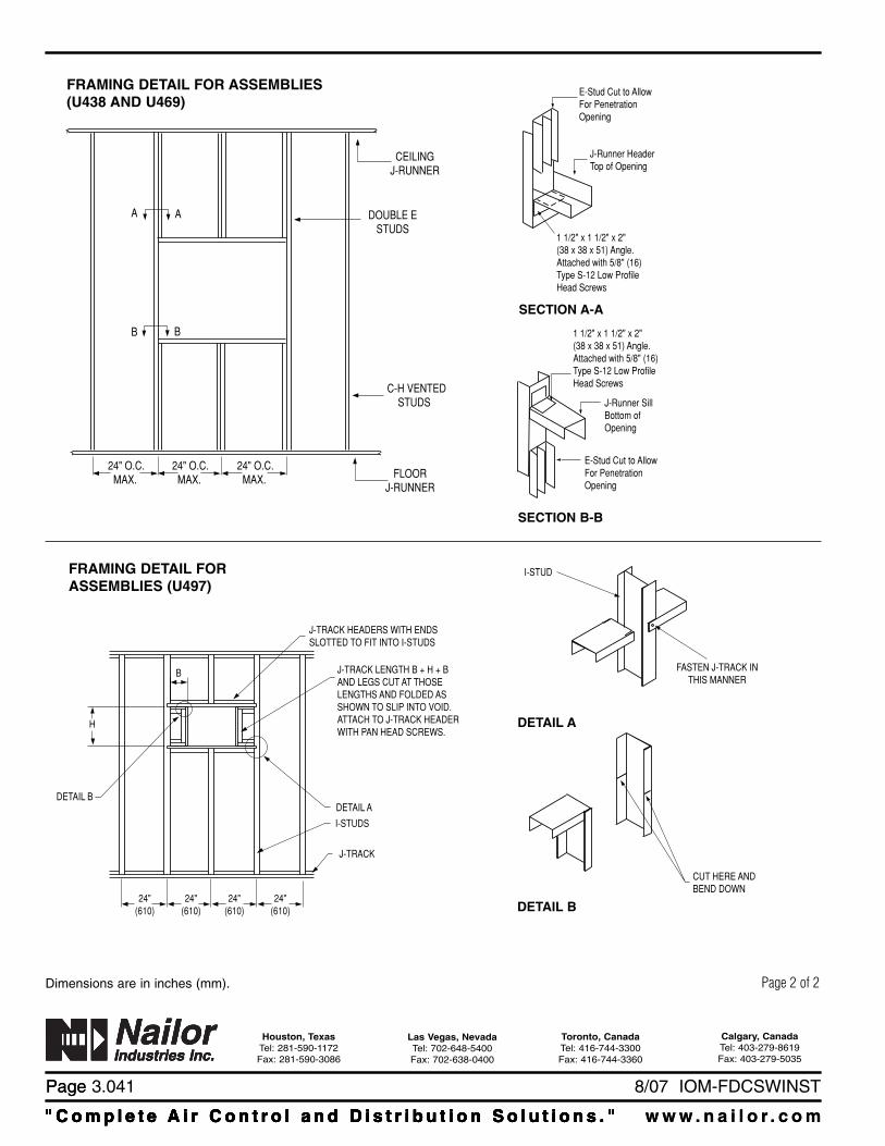
APPLICATION:This vertical fire damper installation is for metal stud framing in UL resistant cavityshaft wall designs (1 and 2 hr.) including Nos. U438, U469 and U497. It differs fromconventional fire damper installations in that it requires retaining angles on one sideof the wall only, which are fastened to the wall as well as the damper for openingsizes up to 48" W x 36" H (1219 x 914). Larger openings require retaining angleson both sides.
GENERAL INSTALLATION:1. Expansion Clearance: Opening in wall shall be a minimum 1/8" (3) per
linear foot larger than overall size of damper and sleeve assembly in eitherdimension. Maximum opening not to exceed 1/8" (3) per foot plus two inches.Opening shall not be less than 1/4" (6) larger for any size damper and sleeveassembly.
2. Damper Sleeve: Sleeve gauge shall be at least equal to the gauge of the ductas defined by the appropriate SMACNA duct construction standard anddescribed in NFPA 90A when one or more of the following duct-sleeveconnections are used (TDC/TDF breakaway, ductmate breakaway, plain "S" slip,hemmed "S" slip, standing "S" slip, reinforced standing "S" slip, inside slipjoint, and double "S" slip.)In addition, the following connections are acceptable:A. On rectangular duct, a standing S slip connection, with two #10 sheet
metal screws on each side and bottom of the joint and with duct sealant*applied to each connection, may be used.
B. On rectangular duct, a standing S slip connection on top and bottom jointsand flat drive connections on side joints with duct sealant* applied to eachconnection, may be used for dampers 48" x 20" (1219 x 508) and smaller.Plain S and hemmed S slip connections can also be used in lieu of thestanding S connections described above.
C. A round duct may be attached to the round adapter which is part of thedamper sleeve in the following manner:(a) Duct diameters 22" (559) and smaller must use three #10 sheet metalscrews equally spaced around the circumference and with duct sealant*applied to the connection.(b) Duct diameters over 22" (559) up to and including 36" (914) may usefive #10 sheet metal screws equally spaced around the circumference andwith duct sealant* applied to the connection.(c) Duct diameters larger than 36" (914) wide or diameter may use eight#10 sheet metal screws equally spaced around the circumference.*The duct sealant must be PA2084T Duct Sealant Adhesive asmanufactured by Precision or water based DP1010 by Design Polymetrics.
3. If any other duct-sleeve connections are used, sleeve shall be minimum of 16gauge (1.6) for dampers up to 36" w x 24"h (914 x 610) and 14 gauge (1.9) ifdamper width exceeds 36" (914) or height exceeds 24" (610).
4. Damper/Sleeve Attachment: Damper shall be secured to sleeve with 1/4"(6) long welds, 3/16" (5) steel rivets, 1/4" (6) bolts and nuts, #8 sheet metalscrews, or 3/16" (5) buttonloks on both sides at 6" (152) on center and 2" (51)maximum from the corner of the damper on all four sides. For field assembledsleeves, the inner dimensions of the sleeve shall be equal to the outerdimensions of the damper.
NOTE 1SEE NOTE 5
DAMPER
1 HOUR PARTITION
2 HOUR PARTITION
5. Retaining Angles:A. Shall be a minimum of 1 1/2" x 1 1/2" x 16 gauge (38 x 38 x
1.61) and fastened with #10 bolts or screws, 1/2" (13) longwelds, or 3/16" (5) rivets to sleeve at a maximum spacing of 8"(152) O.C. and not more than 2" (51) from each end with aminimum of two connections on each side, top and bottom (SeeIllustration).Nailor 'Quick-Set' Retaining Angles can be used in lieu ofconventional mounting angles. Retaining angles must overlapthe structural opening by 1" (25) minimum.
B. Retaining angles screw to wall with #10 screws. Use a minimum oftwo fasteners per side, top and bottom 12" (305) O.C. maximum.
6. See framing detail on next page for opening preparation.Refer to the appropriate installation supplements for the followingrequirements:
Ductmate Breakaway Connection Doc. FDDMINSTFlange System Breakaway Connections Doc. FDTDCFINST'Quick-Set' Retaining Angles. Doc. FDQSRA
7. Refer to Underwriters Laboratories Inc. Fire Resistance DirectoryVol. II for details on UL Design No. U438, U469 and U497.
Page 1 of 2 Dimensions are in inches (mm).
Refer to theUL ClassificationMarking on theProduct
Page
" C o m p l e t e A i r C o n t r o l a n d D i s t r i b u t i o n S o l u t i o n s . " w w w . n a i l o r . c o m
Calgary, CanadaTel: 403-279-8619Fax: 403-279-5035
Houston, TexasTel: 281-590-1172Fax: 281-590-3086
Toronto, CanadaTel: 416-744-3300Fax: 416-744-3360
Las Vegas, NevadaTel: 702-648-5400Fax: 702-638-0400
" C o m p l e t e A i r C o n t r o l a n d D i s t r i b u t i o n S o l u t i o n s . "" C o m p l e t e A i r C o n t r o l a n d D i s t r i b u t i o n S o l u t i o n s . "" C o m p l e t e A i r C o n t r o l a n d D i s t r i b u t i o n S o l u t i o n s . "
Page 3.041 8/07 IOM-FDCSWINST
" C o m p l e t e A i r C o n t r o l a n d D i s t r i b u t i o n S o l u t i o n s . " w w w . n a i l o r . c o m
AA
BB
24" O.C. MAX.
CEILING J-RUNNER
DOUBLE E STUDS
C-H VENTED STUDS
FLOOR J-RUNNER
24" O.C. MAX.
24" O.C. MAX.
1 1/2" x 1 1/2" x 2"(38 x 38 x 51) Angle.Attached with 5/8" (16)Type S-12 Low ProfileHead Screws
E-Stud Cut to AllowFor PenetrationOpening
J-Runner HeaderTop of Opening
E-Stud Cut to AllowFor PenetrationOpening
1 1/2" x 1 1/2" x 2"(38 x 38 x 51) Angle. Attached with 5/8" (16)Type S-12 Low ProfileHead Screws
J-Runner SillBottom ofOpening
FRAMING DETAIL FOR ASSEMBLIES(U438 AND U469)
SECTION A-A
SECTION B-B
FRAMING DETAIL FORASSEMBLIES (U497)
DETAIL B
H
24"(610)
B
J-TRACK HEADERS WITH ENDSSLOTTED TO FIT INTO I-STUDS
J-TRACK LENGTH B + H + B AND LEGS CUT AT THOSELENGTHS AND FOLDED AS SHOWN TO SLIP INTO VOID.ATTACH TO J-TRACK HEADERWITH PAN HEAD SCREWS.
DETAIL A
I-STUDS
J-TRACK
24"(610)
24"(610)
24"(610)
I-STUD
FASTEN J-TRACK INTHIS MANNER
CUT HERE ANDBEND DOWN
DETAIL A
DETAIL B
Page 2 of 2Dimensions are in inches (mm).

Nailor Industries Inc. reserves the right to change any information concerning product or specification without notice or obligation.
Page 3.0922/05 IOM-FDEFS
Dimensions are in inches (mm).
Figure 1. Sleeve Extension Detail
SUPPLEMENTARY INSTALLATION INSTRUCTIONSFIRE AND COMBINATION FIRE/SMOKE DAMPERFIELD EXTENSION OF FACTORY SLEEVES
APPLICATION:Factory installed sleeves may sometimes need to be extendedin the field when of insufficient length for ductwork connectionrelative to the depth of the fire partition. This supplementinstallation instruction provides details for attachment of thesleeve extension. Consult Authority Having Jurisdiction forapproval.
NOTES (Refer to Figure 1):1. Sleeve extension must be same material and gauge as
factory sleeve.
2. The inside dimensions of the sleeve extension must be thesame dimensions as the outside dimensions of the factorysleeve.
3. Sleeve extension must overlap the factory sleeve aminimum of 1" (25).
4. All four sides of the sleeve extension must be attached tothe factory sleeve. Attachments must be spaced amaximum of 6" (152) on center and a maximum of 2" (51)from corners. A minimum of 2 attachments per side (8 perdamper) are required. Attach the sleeve extension using1/2" (13) long tack or spot welds, #10 sheet metal screws,1/4" (6.35) dia. bolts and nuts or 3/16" (5) steel pop rivets.
5. Products with a smoke leakage rating require that the jointbetween the two sleeves be sealed with a continuous 1/8"(3) bead of GE RTV108 or Dow Corning RTV732 siliconesealant.
6. Sleeve extensions can be made to either end of the factorysleeve. However, the sleeve cannot extend beyond the firepartition more than 6" (152) on either side or 16" (406) onone side if equipped with an actuator or integral accessdoor.
7. The joint created by the factory sleeve and sleeve extensioncannot be in the plane of the partition.
Refer to the Following Installation Instructions:Curtain Type Fire Dampers (D)0100 & (D)0500 FDINSTCurtain Type Fire Dampers 0200 & 0500 Thinline FDTINSTMulti-Blade Fire Dampers 1200 & 1250 MBFDINSTCombination Fire/Smoke Dampers 1220 1220INSTCombination Fire/Smoke Dampers 1270 1270INST
THE JOINT AT WHICHBOTH SLEEVES ARECOMBINED MUST BEOUTSIDE THE FIRE RATED BARRIER ANDCAULKED WITH ANAPPROVED UL SEALANT.
SLEEVE EXTENSION(ATTACHED TO EITHEREND OF EXISTINGSLEEVE PERINSTRUCTIONS).
FIRE RATEDPARTITION
MIN. 1" (25)OVERLAP
FIRE ORFIRE / SMOKEDAMPER
Refer to theUL ClassificationMarking on theProduct

Page
" C o m p l e t e A i r C o n t r o l a n d D i s t r i b u t i o n S o l u t i o n s . " w w w . n a i l o r . c o m
Calgary, CanadaTel: 403-279-8619Fax: 403-279-5035
Houston, TexasTel: 281-590-1172Fax: 281-590-3086
Toronto, CanadaTel: 416-744-3300Fax: 416-744-3360
Las Vegas, NevadaTel: 702-648-5400Fax: 702-638-0400
Page 3.093 2/05 IOM-FDEFS
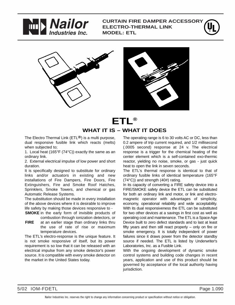
Page 1.0905/02 IOM-FDETL
CURTAIN FIRE DAMPER ACCESSORYELECTRO-THERMAL LINKMODEL: ETL
Nailor Industries Inc. reserves the right to change any information concerning product or specification without notice or obligation.
The Electro Thermal Link (ETL®) is a multi purpose,dual responsive fusible link which reacts (melts)when subjected to;1. Local heat (165°F (74°C)) exactly the same as anordinary link.2. External electrical impulse of low power and shortduration.It is specifically designed to substitute for ordinarylinks and/or actuators in existing and newinstallations of Fire Dampers, Fire Doors, FireExtinguishers, Fire and Smoke Roof Hatches,Sprinklers, Smoke Towers, and chemical or gasAutomatic Release Systems.The substitution should be made in every installationof the above devices where it is desirable to improvelife safety by making those devices responsive to -SMOKE in the early form of invisible products of
combustion through ionization detectors, orFIRE at an earlier stage than ordinary links thru
the use of rate of rise or maximumtemperature devices.
The ETL's electro-response is the unique feature. Itis not smoke responsive of itself, but its powerrequirement is so low that it can be released with anelectrical impulse from any smoke detector's powersource. It is compatible with every smoke detector onthe market in the United States today.
The operating range is 6 to 30 volts AC or DC, less than0.2 ampere of trip current required, and 1/2 millisecond(.0005 second) response at 24 v. The electricalresponse is a trigger for the chemical heating of thecenter element which is a self-contained exo-thermicreactor, yielding no noise, smoke, or gas - just quickheat to open the link in seven seconds.The ETL's thermal response is identical to that ofordinary fusible links of identical temperature (165°F(74°C)) and strength (40#) rating.In its capacity of converting a FIRE safety device into aFIRE/SMOKE safety device the ETL can be substitutedfor both an ordinary link and motor, or link and electro-magnetic operator with advantages of simplicity,economy, operational reliability and wide acceptability.With its dual responsiveness the ETL can be substitutedfor two other devices at a savings in first cost as well asoperating cost and maintenance. The ETL is a Space AgeDevice built to zero defect standards and to last at leastfifty years and then still react properly – only on fire orsmoke emergency. It is totally independent of powerfailures since it draws power from the detector standbysource if needed. The ETL is listed by Underwriter'sLaboratories, Inc. as a Fusible Link.With the ongoing development of dynamic smokecontrol systems and building code changes in recentyears, application and use of this product should begoverned by acceptance of the local authority havingjurisdiction.
ETL®
WHAT IT IS – WHAT IT DOES

Page 1.091 5/02 IOM-FDETL
" C o m p l e t e A i r C o n t r o l a n d D i s t r i b u t i o n S o l u t i o n s . " w w w . n a i l o r . c o m
Calgary, CanadaTel: 403-279-8619Fax: 403-279-5035
Ft. Lauderdale, FloridaTel: 954-351-2444Fax: 954-351-2440
Houston, TexasTel: 281-590-1172Fax: 281-590-3086
Toronto, CanadaTel: 416-744-3300Fax: 416-744-3360
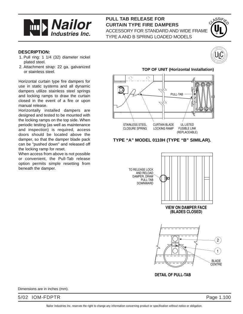
Page 1.1005/02 IOM-FDPTR
PULL TAB RELEASE FOR CURTAIN TYPE FIRE DAMPERSACCESSORY FOR STANDARD AND WIDE FRAMETYPE AAND B SPRING LOADED MODELS
Nailor Industries Inc. reserves the right to change any information concerning product or specification without notice or obligation.
STAINLESS STEELCLOSURE SPRING
CURTAIN BLADELOCKING RAMP
UL LISTEDFUSIBLE LINK
(REPLACEABLE)
PULL-TAB
VIEW ON DAMPER FACE(BLADES CLOSED)
TO RELEASE LOCKAND RELOAD
DAMPER, DRAWPULL-TAB
DOWNWARD
BLADECENTRE
1
2
TYPE “A” MODEL 0110H (TYPE “B” SIMILAR).
DETAIL OF PULL-TAB
TOP OF UNIT (Horizontal Installation)
Dimensions are in inches (mm).
DESCRIPTION:1. Pull ring: 1 1/4 (32) diameter nickel
plated steel.2. Attachment strap: 22 ga. galvanized
or stainless steel.
Horizontal curtain type fire dampers foruse in static systems and all dynamicdampers utilize stainless steel springsand locking ramps to draw the curtainclosed in the event of a fire or uponmanual release. Horizontally installed dampers aredesigned and tested to be mounted withthe locking ramps on the top side. Whenperiodic testing (as well as maintenanceand inspection) is required, accessdoors should be located above thedamper, so that the damper blade packcan be "pushed down" and released offthe locking ramp for reset.When access from above is not possibleor convenient, the Pull-Tab releaseoption permits simple resetting frombeneath the damper.

Page 1.101 5/02 IOM-FDPTR
" C o m p l e t e A i r C o n t r o l a n d D i s t r i b u t i o n S o l u t i o n s . " w w w . n a i l o r . c o m
Calgary, CanadaTel: 403-279-8619Fax: 403-279-5035
Ft. Lauderdale, FloridaTel: 954-351-2444Fax: 954-351-2440
Houston, TexasTel: 281-590-1172Fax: 281-590-3086
Toronto, CanadaTel: 416-744-3300Fax: 416-744-3360
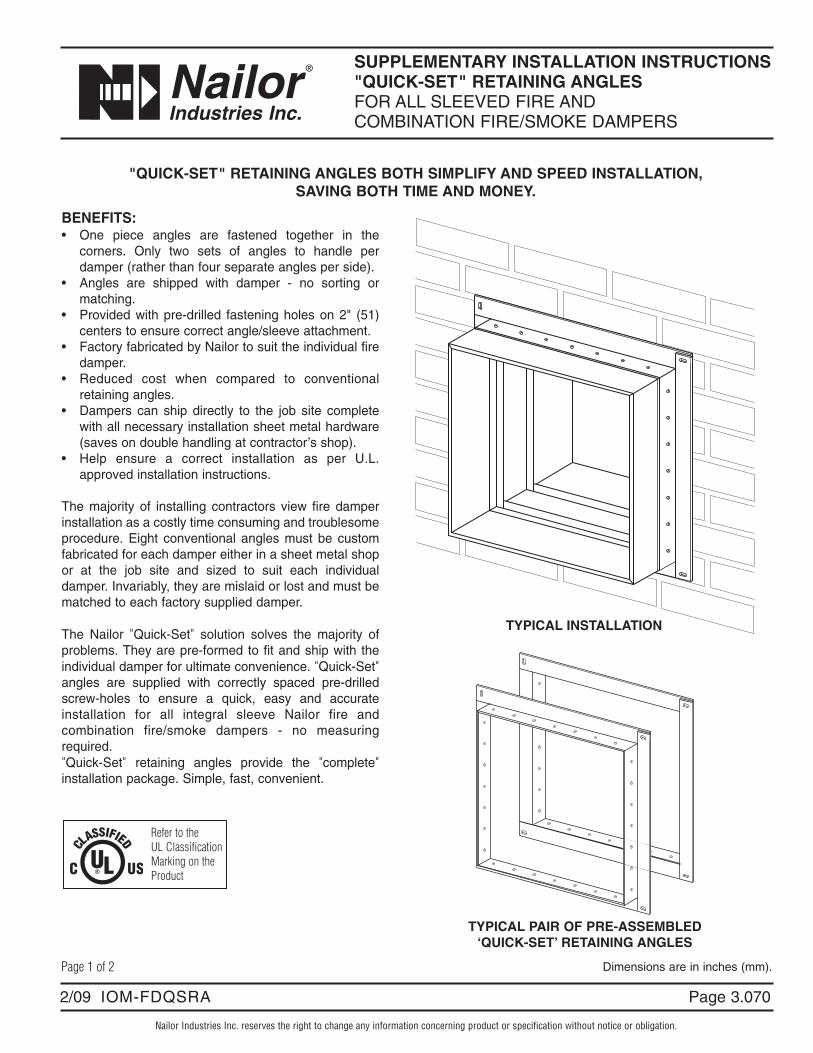
Nailor Industries Inc. reserves the right to change any information concerning product or specification without notice or obligation.
Page 3.0702/09 IOM-FDQSRA
SUPPLEMENTARY INSTALLATION INSTRUCTIONS"QUICK-SET" RETAINING ANGLESFOR ALL SLEEVED FIRE ANDCOMBINATION FIRE/SMOKE DAMPERS
BENEFITS:• One piece angles are fastened together in the
corners. Only two sets of angles to handle perdamper (rather than four separate angles per side).
• Angles are shipped with damper - no sorting ormatching.
• Provided with pre-drilled fastening holes on 2" (51)centers to ensure correct angle/sleeve attachment.
• Factory fabricated by Nailor to suit the individual firedamper.
• Reduced cost when compared to conventionalretaining angles.
• Dampers can ship directly to the job site completewith all necessary installation sheet metal hardware(saves on double handling at contractor’s shop).
• Help ensure a correct installation as per U.L.approved installation instructions.
The majority of installing contractors view fire damperinstallation as a costly time consuming and troublesomeprocedure. Eight conventional angles must be customfabricated for each damper either in a sheet metal shopor at the job site and sized to suit each individualdamper. Invariably, they are mislaid or lost and must bematched to each factory supplied damper.
The Nailor "Quick-Set" solution solves the majority ofproblems. They are pre-formed to fit and ship with theindividual damper for ultimate convenience. "Quick-Set"angles are supplied with correctly spaced pre-drilledscrew-holes to ensure a quick, easy and accurateinstallation for all integral sleeve Nailor fire andcombination fire/smoke dampers - no measuringrequired."Quick-Set" retaining angles provide the "complete"installation package. Simple, fast, convenient.
TYPICAL PAIR OF PRE-ASSEMBLED‘QUICK-SET’ RETAINING ANGLES
"QUICK-SET" RETAINING ANGLES BOTH SIMPLIFY AND SPEED INSTALLATION, SAVING BOTH TIME AND MONEY.
TYPICAL INSTALLATION
Page 1 of 2 Dimensions are in inches (mm).
Refer to theUL ClassificationMarking on theProduct
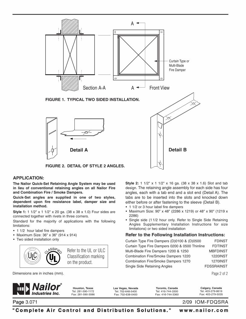
Page
" C o m p l e t e A i r C o n t r o l a n d D i s t r i b u t i o n S o l u t i o n s . " w w w . n a i l o r . c o m
Calgary, CanadaTel: 403-279-8619Fax: 403-279-5035
Houston, TexasTel: 281-590-1172Fax: 281-590-3086
Toronto, CanadaTel: 416-744-3300Fax: 416-744-3360
Las Vegas, NevadaTel: 702-648-5400Fax: 702-638-0400
" C o m p l e t e A i r C o n t r o l a n d D i s t r i b u t i o n S o l u t i o n s . "
Page 3.071 2/09 IOM-FDQSRA
" C o m p l e t e A i r C o n t r o l a n d D i s t r i b u t i o n S o l u t i o n s . " w w w . n a i l o r . c o m
Section A-A Front ViewA
A
Curtain Type orMulti-BladeFire Damper
FIGURE 2. DETAIL OF STYLE 2 ANGLES.
Page 2 of 2Dimensions are in inches (mm).
APPLICATION:The Nailor Quick-Set Retaining Angle System may be usedin lieu of conventional retaining angles on all Nailor Fireand Combination Fire / Smoke Dampers.Quick-Set angles are supplied in one of two styles,dependent upon fire resistance label, damper size andinstallation method.
Style 1: 1 1/2" x 1 1/2" x 20 ga. (38 x 38 x 1.0) Four sides areconnected together with rivets in three corners.Standard for the majority of applications with the followinglimitations:• 1 1/2 hour label fire dampers• Maximum Size: 36" x 36" (914 x 914)• Two sided installation only
Style 2: 1 1/2" x 1 1/2" x 16 ga. (38 x 38 x 1.6) Slot and tabdesign. The retaining angle assembly for each side has fourangles, each with a tab end and a slot end (Detail A). Thetabs are to be inserted into the slots and knocked downeither before or after fastening to the sleeve (Detail B).• 1 1/2 or 3 hour label fire dampers• Maximum Size: 90" x 48" (2286 x 1219) or 48" x 90" (1219 x
2286)• Single side (1 1/2 hour only. Refer to Single Side Retaining
Angles Supplementary Installation Instructions for sizelimitations) or two sided installation
Refer to the Following Installation Instructions:Curtain Type Fire Dampers (D)0100 & (D)0500 FDINSTCurtain Type Fire Dampers 0200 & 0500 Thinline FDTINSTMulti-Blade Fire Dampers 1200 & 1250 MBFDINSTCombination Fire/Smoke Dampers 1220 1220INSTCombination Fire/Smoke Dampers 1270 1270INSTSingle Side Retaining Angles FDSSRAINST
FIGURE 1. TYPICAL TWO SIDED INSTALLATION.
Detail A Detail B
Refer to the UL or ULC Classification marking on the product.

Nailor Industries Inc. reserves the right to change any information concerning product or specification without notice or obligation.
Page 3.0803/19 IOM-FDS
SUPPLEMENTARY INSTALLATION INSTRUCTIONSOPTIONAL SEALING OF FIRE DAMPERS AND COMBINATION FIRE/SMOKE DAMPERSIN WALL/PARTITION OR FLOOR OPENINGS
Nailor Industries Inc. reserves the right to change any information concerning product or specification without notice or obligation.
Dimensions are in inches (mm).
Figure 1. Damper ducted both sides.
ITEMS1. Fire Rated Wall or Floor2. Damper3. Retaining Angles4. Sleeve5. Retaining Plate6. Mounting Tabs7. Sealant (refer to text for specific sealant)
APPLICATION:Application of sealant between the retaining angles, retaining plates, or sleeve retaining flange and the fire rated wall or floor as applicable to the damper installation is not required by UL as a standard procedure. However, if an airtight seal is required by specification or local building code, sealant shall be applied as shown.
METHODFollow the sealant manufacturers’ directions; remove dirt, grease, and moisture from the surfaces to be sealed. Apply a continuous bead of Dow Corning RTV732, Hilti Corporation FS-One, Nuco Inc. Self-Seal GG-200, Johns Manville Firetemp C1 or GE RTV108 sealant. Location of sealant should be as shown in Figures 1 through 4 and may be applied on one or both sides of the fire separation, as applicable to the model specific installation.
IMPORTANT:Do not apply sealant within the required expansion gap between the damper and the fire rated wall or floor.Press the surface of the sealant in place to dispel any air. Allow sealant to set and become tack-free before operating the damper.Refer to the appropriate damper installation instructions for details on damper installation.
1
7
26
43
1 7
3 4
2
7 1 2 4 1 7
2
5
Figure 2. Damper sleeve with tabs for grille mounting
Figure 3. Out of Wall damper with flanged sleeve for grille mounting
Figure 4. Round damper

Page 3.081
“ C o m p l e t e A i r C o n t r o l a n d D i s t r i b u t i o n S o l u t i o n s . ” w w w . n a i l o r . c o m
Calgary, CanadaTel: 403-279-8619Fax: 403-279-5035
Houston, TexasTel: 281-590-1172Fax: 281-590-3086
Toronto, CanadaTel: 416-744-3300Fax: 416-744-3360
Las Vegas, NevadaTel: 702-648-5400Fax: 702-638-0400
3/19 IOM-FDS
" C o m p l e t e A i r C o n t r o l a n d D i s t r i b u t i o n S o l u t i o n s . "
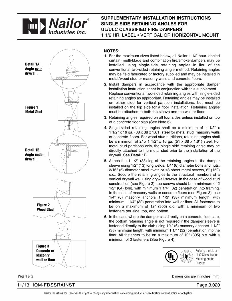
Nailor Industries Inc. reserves the right to change any information concerning product or specification without notice or obligation.
Page 3.02011/13 IOM-FDSSRAINST
SUPPLEMENTARY INSTALLATION INSTRUCTIONS SINGLE-SIDE RETAINING ANGLES FOR UL/ULC CLASSIFIED FIRE DAMPERS1 1/2 HR. LABEL • VERTICAL OR HORIZONTAL MOUNT
Dimensions are in inches (mm).
NOTES:1. For the maximum sizes listed below, all Nailor 1 1/2 hour labeled
curtain, multi-blade and combination fire/smoke dampers may beinstalled using single-side retaining angles in lieu of theconventional two-sided retaining angle method. Retaining anglesmay be field fabricated or factory supplied and may be installed inmetal/wood stud or masonry walls and concrete floors.
2. Install dampers in accordance with the appropriate damperinstallation instruction sheet in conjunction with this supplement. Replace conventional two-sided retaining angles with single-sidedretaining angles as appropriate. Retaining angles may be installedon either side for vertical partition installations, but must beinstalled on the top side for a floor installation. Retaining anglesmust be attached to both the sleeve and the wall or floor.
3. Retaining angles required on all four sides unless installed on topof a concrete floor slab (See Note 6).
4. Single-sided retaining angles shall be a minimum of 1 1/2" x 1 1/2" x 16 ga. (38 x 38 x 1.61) steel for metal stud, masonry wallsor concrete floors. For wood stud partitions, retaining angles shallbe a minimum of 2" x 1 1/2" x 16 ga. (51 x 38 x 1.61) steel. Formetal stud partitions only, the single-side retaining angle may bedirectly attached to the metal stud prior to the installation of thedrywall. See Detail 1B.
5. Attach the 1 1/2" (38) leg of the retaining angles to the dampersleeve using 1/2" (13) long welds, 1/4" (6) diameter bolts and nuts,3/16" (5) diameter steel rivets or #8 sheet metal screws, 6" (152)o.c.. Secure the retaining angles to the structural members of avertical drywall wall using drywall screws. In the case of wood studconstruction (see Figure 2), the screws should be a minimum of 21/2" (64) long, with minimum 1 1/4" (32) penetration into framing.In the case of masonry walls or concrete floors (see Figure 3), use1/4" (6) masonry anchors 1 1/2" (38) minimum length, withminimum 1 1/4" (32) penetration into wall or floor. All fasteners tobe on a maximum of 12" (305) o.c. with a minimum of twofasteners per side, top, and bottom.
6. In the case where the damper sits directly on a concrete floor slab,the bottom retaining angle is not required if the damper sleeve isfastened directly to the slab using 1/4" (6) masonry anchors 1 1/2"(38) minimum length, with minimum 1 1/4" (32) penetration into thefloor. All fasteners to be on a maximum of 12" (305) o.c. with aminimum of 2 fasteners (See Figure 4).
Detail 1AAngle overdrywall.
Figure 1Metal Stud
Detail 1BAngle underdrywall.
Figure 2Wood Stud
Figure 3Concrete orMasonrywall or floor
Refer to the UL or ULC ClassificationMarking on theProduct
Page 1 of 2
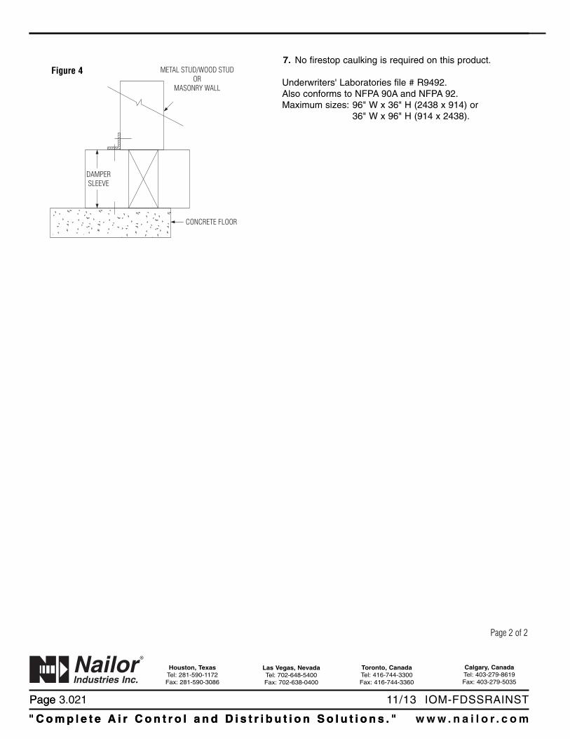
Page
" C o m p l e t e A i r C o n t r o l a n d D i s t r i b u t i o n S o l u t i o n s . " w w w . n a i l o r . c o m
Calgary, CanadaTel: 403-279-8619Fax: 403-279-5035
Houston, TexasTel: 281-590-1172Fax: 281-590-3086
Toronto, CanadaTel: 416-744-3300Fax: 416-744-3360
Las Vegas, NevadaTel: 702-648-5400Fax: 702-638-0400
" C o m p l e t e A i r C o n t r o l a n d D i s t r i b u t i o n S o l u t i o n s . "
Page 3.021 11/13 IOM-FDSSRAINST
7. No firestop caulking is required on this product.
Underwriters' Laboratories file # R9492.Also conforms to NFPA 90A and NFPA 92.Maximum sizes: 96" W x 36" H (2438 x 914) or
36" W x 96" H (914 x 2438).
Figure 4 METAL STUD/WOOD STUDOR
MASONRY WALL
CONCRETE FLOOR
DAMPERSLEEVE
Page 2 of 2
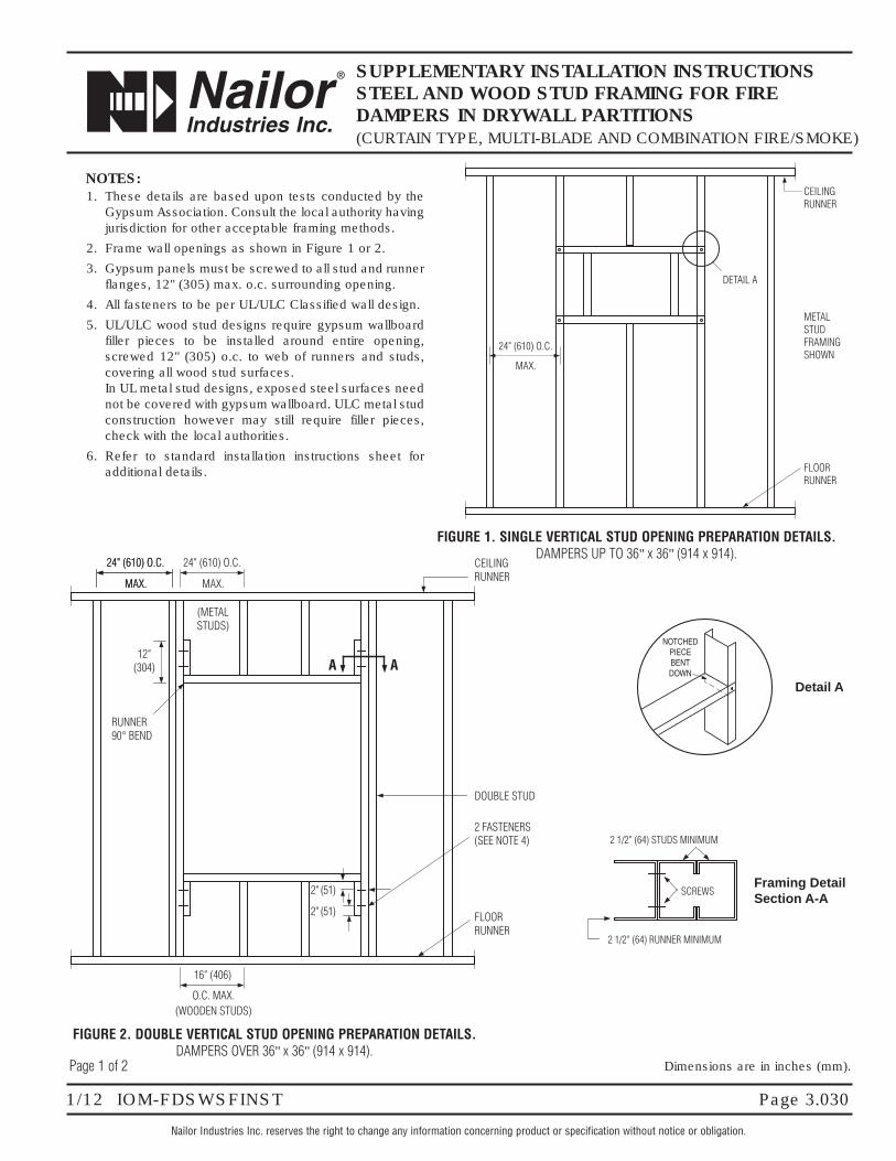
Nailor Industries Inc. reserves the right to change any information concerning product or specification without notice or obligation.
Page 3.0301/12 IOM-FDSWSFINST
SUPPLEMENTARY INSTALLATION INSTRUCTIONSSTEEL AND WOOD STUD FRAMING FOR FIREDAMPERS IN DRYWALL PARTITIONS(CURTAIN TYPE, MULTI-BLADE AND COMBINATION FIRE/SMOKE)
RUNNER90° BEND
FLOORRUNNER
2" (51)
2" (51)
AA12"
(304)
MAX.
(METALSTUDS)
MAX.
24" (610) O.C. 24" (610) O.C.
MAX.
24" (610) O.C.
O.C. MAX.(WOODEN STUDS)
CEILINGRUNNER
2 FASTENERS(SEE NOTE 4)
DOUBLE STUD
16" (406)
NOTES:1. These details are based upon tests conducted by the
Gypsum Association. Consult the local authority havingjurisdiction for other acceptable framing methods.
2. Frame wall openings as shown in Figure 1 or 2.
3. Gypsum panels must be screwed to all stud and runnerflanges, 12" (305) max. o.c. surrounding opening.
4. All fasteners to be per UL/ULC Classified wall design.
5. UL/ULC wood stud designs require gypsum wallboardfiller pieces to be installed around entire opening,screwed 12" (305) o.c. to web of runners and studs,covering all wood stud surfaces.In UL metal stud designs, exposed steel surfaces neednot be covered with gypsum wallboard. ULC metal studconstruction however may still require filler pieces,check with the local authorities.
6. Refer to standard installation instructions sheet foradditional details.
2 1/2" (64) STUDS MINIMUM
2 1/2" (64) RUNNER MINIMUM
SCREWSFraming DetailSection A-A
Dimensions are in inches (mm).
FLOORRUNNER
DETAIL A
MAX.
24" (610) O.C.
CEILINGRUNNER
METALSTUDFRAMINGSHOWN
NOTCHEDPIECEBENTDOWN
Detail A
Page 1 of 2
FIGURE 2. DOUBLE VERTICAL STUD OPENING PREPARATION DETAILS.DAMPERS OVER 36" x 36" (914 x 914).
FIGURE 1. SINGLE VERTICAL STUD OPENING PREPARATION DETAILS.DAMPERS UP TO 36" x 36" (914 x 914).
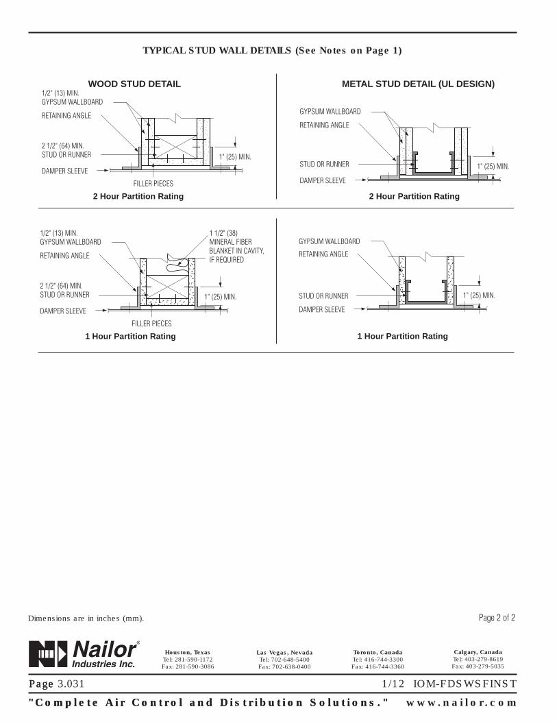
Page
"Comp l e t e A i r C o n t r o l a n d D i s t r i b u t i o n S o l u t i o n s . " www . n a i l o r . c om
Calgary, CanadaTel: 403-279-8619Fax: 403-279-5035
Houston, TexasTel: 281-590-1172Fax: 281-590-3086
Toronto, CanadaTel: 416-744-3300Fax: 416-744-3360
Las Vegas, NevadaTel: 702-648-5400Fax: 702-638-0400
"Comp l e t e A i r C o n t r o l a n d D i s t r i b u t i o n S o l u t i o n s . "
Page 3.031 1/12 IOM-FDSWSFINST
WOOD STUD DETAIL1/2" (13) MIN. GYPSUM WALLBOARD
RETAINING ANGLE
FILLER PIECES
DAMPER SLEEVE
2 Hour Partition Rating
2 1/2" (64) MIN.STUD OR RUNNER 1" (25) MIN.
METAL STUD DETAIL (UL DESIGN)
2 Hour Partition Rating
GYPSUM WALLBOARD
RETAINING ANGLE
DAMPER SLEEVE
STUD OR RUNNER 1" (25) MIN.
1/2" (13) MIN. GYPSUM WALLBOARD
1 1/2" (38)MINERAL FIBERBLANKET IN CAVITY,IF REQUIREDRETAINING ANGLE
FILLER PIECES
DAMPER SLEEVE
1 Hour Partition Rating
2 1/2" (64) MIN.STUD OR RUNNER 1" (25) MIN.
GYPSUM WALLBOARD
RETAINING ANGLE
DAMPER SLEEVE
1 Hour Partition Rating
STUD OR RUNNER 1" (25) MIN.
Page 2 of 2Dimensions are in inches (mm).
TYPICAL STUD WALL DETAILS (See Notes on Page 1)
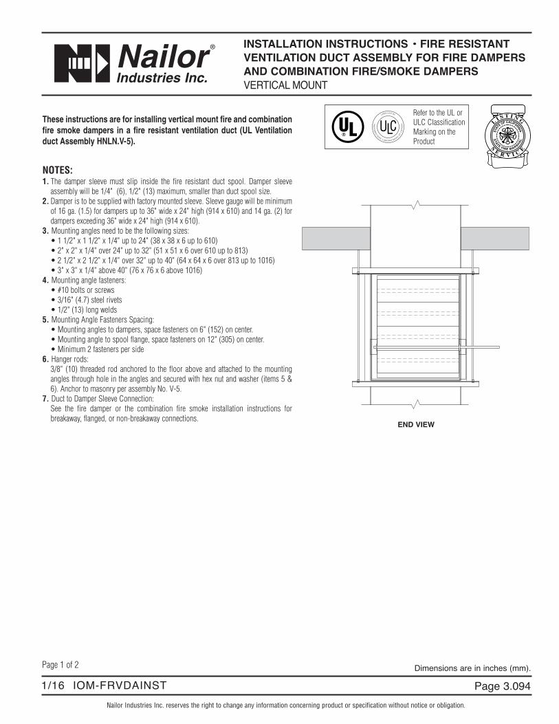
Refer to the UL or ULC ClassificationMarking on theProduct
Nailor Industries Inc. reserves the right to change any information concerning product or specification without notice or obligation.
1/16 IOM-FRVDAINST
INSTALLATION INSTRUCTIONS • FIRE RESISTANTVENTILATION DUCT ASSEMBLY FOR FIRE DAMPERSAND COMBINATION FIRE/SMOKE DAMPERSVERTICAL MOUNT
Page 1 of 2 Dimensions are in inches (mm).
END VIEW
These instructions are for installing vertical mount fire and combinationfire smoke dampers in a fire resistant ventilation duct (UL Ventilationduct Assembly HNLN.V-5).
NOTES:1. The damper sleeve must slip inside the fire resistant duct spool. Damper sleeve
assembly will be 1/4" (6), 1/2" (13) maximum, smaller than duct spool size.2. Damper is to be supplied with factory mounted sleeve. Sleeve gauge will be minimum
of 16 ga. (1.5) for dampers up to 36" wide x 24" high (914 x 610) and 14 ga. (2) fordampers exceeding 36" wide x 24" high (914 x 610).
3. Mounting angles need to be the following sizes:• 1 1/2" x 1 1/2" x 1/4" up to 24" (38 x 38 x 6 up to 610)• 2" x 2" x 1/4" over 24" up to 32" (51 x 51 x 6 over 610 up to 813)• 2 1/2" x 2 1/2" x 1/4" over 32" up to 40" (64 x 64 x 6 over 813 up to 1016)• 3" x 3" x 1/4" above 40" (76 x 76 x 6 above 1016)
4. Mounting angle fasteners:• #10 bolts or screws• 3/16" (4.7) steel rivets• 1/2" (13) long welds
5. Mounting Angle Fasteners Spacing:• Mounting angles to dampers, space fasteners on 6" (152) on center.• Mounting angle to spool flange, space fasteners on 12" (305) on center.• Minimum 2 fasteners per side
6. Hanger rods:3/8" (10) threaded rod anchored to the floor above and attached to the mountingangles through hole in the angles and secured with hex nut and washer (items 5 &6). Anchor to masonry per assembly No. V-5.
7. Duct to Damper Sleeve Connection:See the fire damper or the combination fire smoke installation instructions forbreakaway, flanged, or non-breakaway connections.
Page 3.094
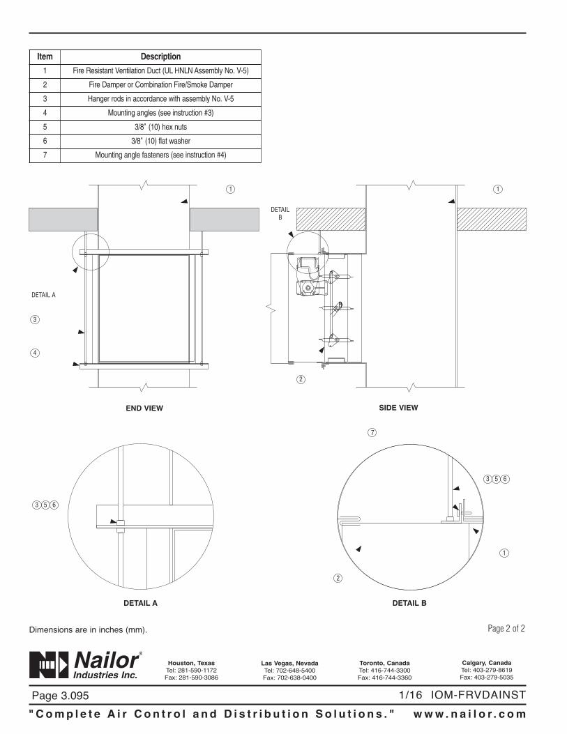
" C o m p l e t e A i r C o n t r o l a n d D i s t r i b u t i o n S o l u t i o n s . " w w w . n a i l o r . c o m
Calgary, CanadaTel: 403-279-8619Fax: 403-279-5035
Houston, TexasTel: 281-590-1172Fax: 281-590-3086
Toronto, CanadaTel: 416-744-3300Fax: 416-744-3360
Las Vegas, NevadaTel: 702-648-5400Fax: 702-638-0400
1/16 IOM-FRVDAINST
Page 2 of 2Dimensions are in inches (mm).
Item Description
1 Fire Resistant Ventilation Duct (UL HNLN Assembly No. V-5)
2 Fire Damper or Combination Fire/Smoke Damper
3 Hanger rods in accordance with assembly No. V-5
4 Mounting angles (see instruction #3)
5 3/8" (10) hex nuts
6 3/8" (10) flat washer
7 Mounting angle fasteners (see instruction #4)
DETAIL A
3
4
1
END VIEW
DETAILB
2
1
SIDE VIEW
653
DETAIL A
2
1
653
7
DETAIL B
Page 3.095
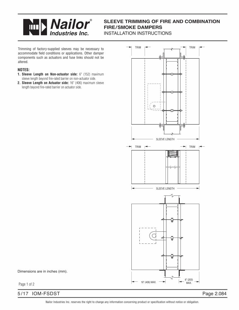
Nailor Industries Inc. reserves the right to change any information concerning product or specification without notice or obligation.
Page 2.0845 /17 IOM-FSDST
SLEEVE TRIMMING OF FIRE AND COMBINATIONFIRE/SMOKE DAMPERS INSTALLATION INSTRUCTIONS
Page 1 of 2
SLEEVE LENGTH
TRIM TRIM
16" (406) MAX.6" (203)MAX.
TRIM TRIM
SLEEVE LENGTH
Trimming of factory-supplied sleeves may be necessary toaccommodate field conditions or applications. Other dampercomponents such as actuators and fuse links should not bealtered.
NOTES:1. Sleeve Length on Non-actuator side: 6" (152) maximum
sleeve length beyond fire-rated barrier on non-actuator side.2. Sleeve Length on Actuator side: 16" (406) maximum sleeve
length beyond fire-rated barrier on actuator side.
Dimensions are in inches (mm).

Page 2.085 5 /17 IOM-FSDST"Comp l e t e A i r C o n t r o l a n d D i s t r i b u t i o n S o l u t i o n s . " www . n a i l o r . c om
Calgary, CanadaTel: 403-279-8619Fax: 403-279-5035
Houston, TexasTel: 281-590-1172Fax: 281-590-3086
Toronto, CanadaTel: 416-744-3300Fax: 416-744-3360
Las Vegas, NevadaTel: 702-648-5400Fax: 702-638-0400
Page 2 of 2