nalco apfc filter calculations
TRANSCRIPT
NALCO Project
Calculation of current through harmonic filters
A. Electrical System Description –
The electrical system in TKII scope consists of 1 No MCC panel feeding the electrical equipment which consists of motor loads (AC squirrel cage type). While some motors are fixed speed type, few are operated through VFD (6 pulse type – model ACS800 of ABB make) for obtaining variable speed operation as per process requirement.
The load details are as under –
Total motor load = xxx kWTotal motor load operated through VFD = 647 kW, consisting of 3 No VFDs supplying 1 No of 315 kW, 1 No of 200 kW and 1 No of 132 kW motors
For improving the overall power factor to 0.9 at the MCC busbar, 1 No power factor improvement panel consisting of capacitors and relay for automatic switching of capacitor banks is also provided. The rating of capacitors in APFC panel is 300 kVAr.
B. Need for provision of harmonic filters –
As per client specifications the harmonic distortion at MCC busbar is to be kept within the limits specified by IEEE-519.
The data of actual harmonic current and voltage distortion under working conditions has been made available by M/s ABB. As per the information furnished the details are as below –
THD – Voltage = 5.5%THD – Current = 24%
The current distortion is seen to be mainly caused by following harmonic orders –
5th harmonic = 32% (298 A)7th harmonic = 11% (102 A)11th harmonic = 7% (65 A)
Harmonic currents of higher order are found to be negligible.
Considering the above data, it is proposed to install reactors in series with few capacitor banks to work as filters for absorbing the harmonic currents.
Out of total capacitor rating of 300 kVAr, following capacitor banks are proposed for using as harmonic filter –
Filter-1: Common for 5th/7th harmonic = 90 kVAr Filter-2 : For 11th harmonic = 10 kVAr
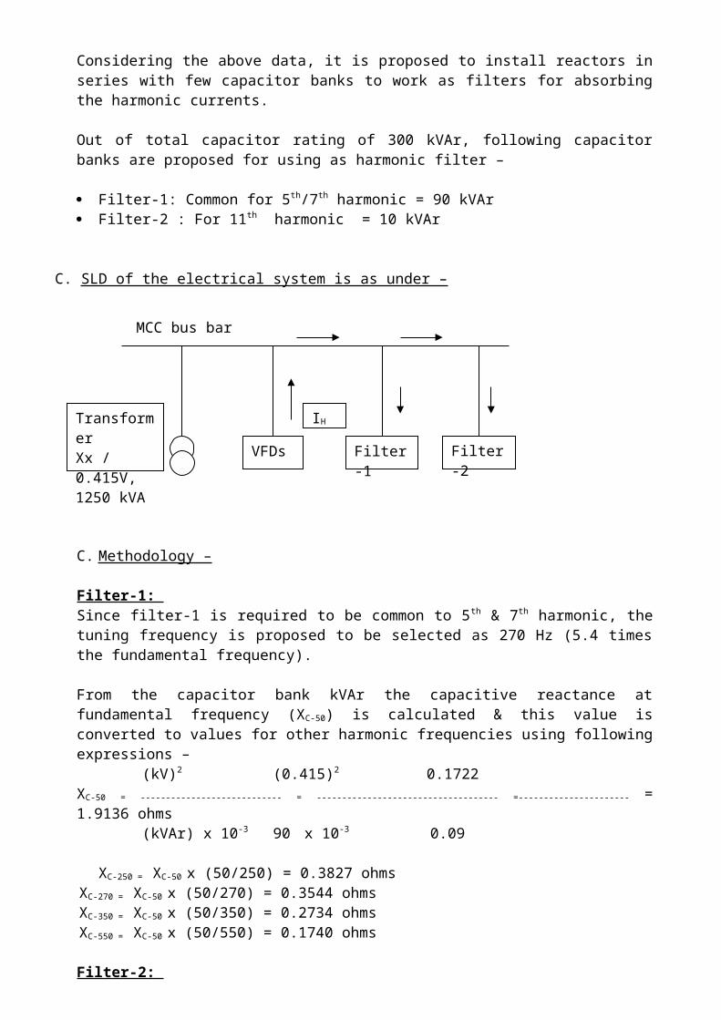
C. SLD of the electrical system is as under –
C. Methodology –
Filter-1: Since filter-1 is required to be common to 5th & 7th harmonic, the tuning frequency is proposed to be selected as 270 Hz (5.4 times the fundamental frequency).
From the capacitor bank kVAr the capacitive reactance at fundamental frequency (XC-50) is calculated & this value is converted to values for other harmonic frequencies using following expressions –
(kV)2 (0.415)2 0.1722XC-50 = ---------------------------- = ------------------------------------ =---------------------- = 1.9136 ohms
(kVAr) x 10-3 90 x 10-3 0.09
XC-250 = XC-50 x (50/250) = 0.3827 ohmsXC-270 = XC-50 x (50/270) = 0.3544 ohmsXC-350 = XC-50 x (50/350) = 0.2734 ohmsXC-550 = XC-50 x (50/550) = 0.1740 ohms
Filter-2: Since filter-2 is required for 11th harmonic, the tuning frequency is proposed to be selected as 530 Hz (10.6 times the fundamental frequency).
From the capacitor bank kVAr the capacitive reactance at fundamental frequency (XC-50) is calculated & this value is converted to values for other harmonic frequencies using following expressions –
(kV)2 (0.415)2 0.1722XC-50 = ---------------------------- = ------------------------------------ =---------------------- = 17.222 ohms
(kVAr) x 10-3 10 x 10-3 0.01
XC-250 = XC-50 x (50/250) = 3.4445 ohmsXC-270 = XC-50 x (50/270) = 3.1894 ohmsXC-350 = XC-50 x (50/350) = 2.4604 ohmsXC-550 = XC-50 x (50/550) = 1.5657 ohms
Calculation of reactor / inductance value –
VFDs Filter-1 Filter-2
MCC bus bar
TransformerXx / 0.415V,1250 kVA
IH
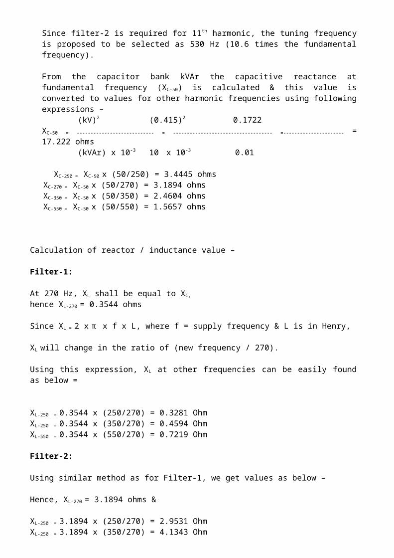
Filter-1:
At 270 Hz, XL shall be equal to XC,
hence XL-270 = 0.3544 ohms
Since XL = 2 x π x f x L, where f = supply frequency & L is in Henry,
XL will change in the ratio of (new frequency / 270).
Using this expression, XL at other frequencies can be easily found as below =
XL-250 = 0.3544 x (250/270) = 0.3281 OhmXL-250 = 0.3544 x (350/270) = 0.4594 OhmXL-550 = 0.3544 x (550/270) = 0.7219 Ohm
Filter-2:
Using similar method as for Filter-1, we get values as below –
Hence, XL-270 = 3.1894 ohms &
XL-250 = 3.1894 x (250/270) = 2.9531 OhmXL-250 = 3.1894 x (350/270) = 4.1343 OhmXL-550 = 3.1894 x (550/270) = 6.4968 Ohm
For each harmonic frequency, the net impedance will be difference between XL
and XC.
Hence, net impedance values are –
For Filter-1 :
Z250 = XL-250 - XC-250 = 0.3281 – 0.3827 = - 0.0546OhmZ350 = XL-350 - XC-350 = 0.4594 – 0.2734 = 0.1860 OhmZ550 = XL-550 - XC-550 =0.7219 – 0.1740 = 0.5479 Ohm
For Filter-2 :
Z250 = XL-250 - XC-250 = 2.9531 – 3.4450 = - 0.4919 OhmZ350 = XL-350 - XC-350 = 4.1343 – 2.4604 = 1.6739 OhmZ550 = XL-550 - XC-550 =6.4968 – 1.5657 = 4.9311 Ohm
The harmonic currents introduced by the VFD will flow through both filters, with each filter absorbing current in the inverse proportion of the impedances.

That is, for Filter-1 – Z-Filter-2 (- 0.4919)
I-Filter-1-250 = I-250 x ---------------------- = 298 x ---------------------- Z-Filter-1 + Z-Filter-2 (- 0.0546 – 0.4919)
= 268.23 A
Similarly, current distribution for currents of other frequencies can be calculated & results are as below –
I-Filter-1-350 = 91.8 AI-Filter-1-550 = 10.2 A& current through Filter-2 are
I-Filter-2-250 = 29.8 AI-Filter-2-350 = 10.2 AI-Filter-2-550 = 6.5 A
Note: For simplifying the calculation, the value of resistance in filter circuit is assumed as zero.
DOUBT –
For each harmonic current introduced by the VFD, the load will comprise of the 2 filter circuits and the distribution transformer & these can be considered as connected in parallel. Hence the current distribution through the filters will depend upon the actual value of the transformer impedance also.
Impedance of transformer –
kVA = 1250Impedance = 5%Fault kVA = 1250 / 0.05 = 25000Fault current = 25000 / (1.732 x 0.415) = 34781 ATransformer impedance = 240 V / 34781 A = 0.0069 Ohm
Since the actual value of transformer impedance is observed as less than the value of net impedance of Filter-1 & 2 at all harmonic frequencies, will the Filters be able to absorb the harmonic currents as intended? Or will some part of harmonic current flow through the transformer also.