namafph0 - thealarmtech.com · 3=pprg partial point programming - selectively altering the...
TRANSCRIPT

Programming 15088:H 12/23/97 3-1
AM2020AFP1010
CHAPTER THREE
PROGRAMMING

3-2 Programming 15088:H 12/23/97

Programming 15088:H 12/23/97 3-3
Select Partial PointProgramming
Select MESSAGE option tochange Custom User Label.
Select Programming Mode
IntroductionThis chapter covers the programming options of the AM2020/AFP1010 Combination Fire/Security ProtectiveSignaling System and the features available to the operator. This chapter is presented through theperspective of the CRT-2 Monitor. The prompts are displayed on the CRT screen in the order that they appear(top to bottom) on the pages that follow. For programming the control panel from the built-in keypad, anoverview of the panel’s Display Interface Assembly (DIA-2020 or DIA-1010) is illustrated in Chapter Two,Operation. Installation information for the CRT is located in Chapter 1.
MenusAt the top of each sub-menu in this programming guide, a string of keys are displayed to illustrate thesequence of keys needed to reach a particular menu. For example:
D } X 1 X OR 7 X
PasswordsAccess to keypad or menu levels one and two require entry of specific passwords. These levels allow anauthorized programmer to initialize or alter the programming of the AM2020/AFP1010. Level One and LevelTwo entry requirements are defined as follows:
Alter Status Level One password required.Programming Level Two password required.
If the main operator of the system requires access to a function which is password protected, contact thedistributor who installed the system for the required password(s). The AM2020 and AFP1010 are shipped withinitial Level One and Level Two passwords of five zeroes (00000).
NOTEUnacknowledged points must be acknowledged prior to being reprogrammed.
Backspace key VThe Backspace key serves several purposes. At a menu prompt, the Backspace key aborts the selection ofthat option:
ENTER@40@CHARACTER@USER@LABEL:
When entering data, the Backspace key erases the last character or digit entered:
ENTER@40@CHARACTER@USER@LABEL:@NOTIFIER
At certain points during operator or programming functions, the Backspace key aborts all the data just entered.For instance, during Full Point Programming, a particular point must be fully programmed before the controlpanel can use the information. If the Backspace key is pressed at a prompt ( : ) before all parameters (i.e.address, type I.D., equation, etc.) for that point are entered into the control panel, then all previous entries forthat point will be ignored.
About Transponder Rapid All-CallWhen the All Call button is pressed on an AMG connected to an AM2020/AFP1010 panel, an All Call activationsignal is received by the panel. Upon receipt of the All Call signal, the AM2020/AFP1010 panel willimmediately activate all specially programmed XP Transponder "SPKR" circuits. Programming is performedin the XP Transponder using the XRAM-1 (see XP Transponder System Manual).

3-4 Programming 15088:H 12/23/97
About SIB-NETThe SIB-2048A and SIB-NET serial communications boards are available for use on the AM2020/AFP1010system (see Chapter One). For the AM2020/AFP1010 with NOTI�FIRE�NET™ system, only the SIB-NET maybe used. If a SIB-NET board is not installed, specific NOTI�FIRE�NET functions can not be programmed orviewed under Read Status.
NOTEWhen a Network Reporting Terminal (NRT) is present on the NOTI�FIRE�NET, programming and
read status operations should always be performed from the NRT . If an INA is present on theNOTI�FIRE�NET and no NRT is employed, programming and read status operations should be
performed from the INA. Never attempt to perform programming or read status operations from thelocal panel when the same operations are being performed from the NRT or INA. For more informa-
tion on performing read status operations on the NRT or INA, refer to the NRT manual, Document15090 and the INA manual, Document 15092.

Programming 15088:H 12/23/97 3-5
The Initial Programming OutlineFor initial programming of the AM2020 or AFP1010, or for major changes and additions, the following basicprocedure is recommended to prevent errors resulting in reprogramming and wasted time.
• Make copies of the Program Work Sheets (contained in the Glossary) in the back of this manual.
• Use these Work Sheets to record the exact information for every detector, module, annunciator pointand software zone in the system. Pay special attention to the Software Type I.D.s listed in SectionThree. For voice systems, pay close attention to AMG annunciator point commands as described inVoice Alarm Multiplex-2020 manual.
• If a CRT is to be used, configure it as described in Chapter 1.
• Assemble and apply power to the control panel as described in the Installation Chapter (also the VAM-2020 manual, if appropriate). All system boards (including all LIBs) must be physically installed.
• The Level 1 and Level 2 passwords can be changed. The AM2020/AFP1010 is delivered from thefactory with passwords of 00000. Write down or memorize your passwords! To change the passwords,enter the following:
D 00000 X 6 X (1 OR 2) X• If the control panel is to be programmed before installation of LIB SLC Loop devices, the panel will exit
programming and sound the piezo when each programmed device is not detected. To avoid the piezofrom sounding, use the following key sequence (after entering the password):
1 X 7 X y X y X y X VWhen the first device has been programmed into the system, the control panel will report a troublecondition and will exit programming mode. Important: Do not acknowledge this trouble. Reenterprogramming and the control panel will no longer exit programming or sound the piezo for subsequenttrouble conditions.
• For initial system programming, read Full System Programming and answer all the questions in thatsection before entering programming mode. Then, enter Full System Programming and load all theanswers into the control panel.
• Enter Full Point Programming. Use the work sheets developed in the second step of this outline andenter information on all points in the system. Program points in the following order:
1) Annunciator Points 2) Zones 3) Detector Points 4) Module Points
• When devising Control-By-Event equations for a particular device, remember that the label of the firstsoftware zone in the equation will appear on the panel display, along with the label of the device, whenan alarm condition occurs. See Label option in Partial Point Programming section for more information.
• Enter the System Message.
• Install all devices and thoroughly test the entire system. The Walk Test feature can be used to testdevices and their programming.
• Make a hard-copy record of the program on the printer.
• If desired, upload the program to store on an external device (computer hard drive or floppy), seeIntelligent Serial Interface Board Programming.

3-6 Programming 15088:H 12/23/97

Programming 15088:H 12/23/97 3-7
Section OneMain Programming
The Programming Mode is accessed by entering the following (level 2 password required):
D } XAfter entering the Programming Mode, the display will show the Main Programming menu:
PRESS@1=PSYS,2=FSYS,3=PPRG,4=FPRG,5=REMV,6=PSWD,7=MSG,8=HIS@@@@@@@@@@@@@@@@@@:
The Main Programming menu has eight options, where:
1=PSYS Partial System Programming - Selective programming of system-wide functions(number of LIBs, AVPS-24/AVPS-24E*, ISIB, Signal-Silence Inhibit and Cut-out, AlarmVerification, number of annunciator modules, etc.).
2=FSYS Full System Programming - Complete programming of system-wide functions (num-ber of LIBs, AVPS-24/AVPS-24E*, ISIB, Signal-Silence Inhibit and Cutout, Alarm Verifi-cation, number of annunciator modules, etc.).
3=PPRG Partial Point Programming - Selectively altering the operating parameters of LIBSLC Loop devices, software-defined zones and annunciator points.
4=FPRG Full Point Programming - Complete programming of addressable LIB SLC Loop de-vices, software-defined zones, annunciator points and their respective operating pa-rameters.
5=REMV Remove - Permits the selective removal (from control panel memory) of any of thesystem's addressable SLC Loop devices, software-defined zones or annunciatorpoints.
6=PSWD Password - Allows the programmer to assign custom five-digit Level One and LevelTwo passwords.
7=MSG Message - Allows the Level Two programmer to define the custom 40-Character UserLabel displayed on the CRT Monitor and the panel's Liquid Crystal Display (LCD).
8=HIS History - Allows the programmer to enable or disable storage of events and the clear-ing of stored events.
* The number of APS-6R power supplies should be included in the AVPS count.
The Main Programming Menu flow chart is located in Figure 1-1 . Detailed information on the Main Programmingoptions follows.

3-8 Programming 15088:H 12/23/97
Press PROG key
Enter Level 2Password
Select MainProgramming
Menu Option 1-8
1 = PSYS(partial system programming)
3 = PPRG(partial point programming)
4 = FPRG(full point programming)
2 = FSYS(full system programming)
5 = REMV(selective removal ofdevices, zones, etc.)
7 = MSG(assign or alter message
displayed on control panel)
8 = HIS(enable, disable, or clear
history buffer)
6 = PSWD(assign or alter passwords)
ValidPassword?
Yes
No Error Message
Figure 1-1 Main Programming Menu Flow Chart
see Figure 1-2
see Section 1.2
see Figure 1-10
see Figure 1-13
see Section 1.5
see Section 1.6
see Section 1.7
see Figure 1-14

Programming 15088:H 12/23/97 3-9
Section 1.1 Partial System Programming D }X1X1=PSYSOption 1 from the Main Programming menu allows the programmer to change the programming of system-wide functions such as Alarm Verification of detectors, Signal-Silence Inhibit, Signal Cut-out, disabling thepiezo sounder, enabling Rapid Polling, and enabling supervision of peripheral equipment in the system.Additional system parameters, such as the number of AVPS, LIBs, Annunciators and ISIB in the system. TheLIB SLC Loops can also be changed in Partial System Programming.
After selecting option 1 from the Main Programming menu, the display will show the Partial SystemProgramming submenu:
PRESS@1=INST,2=STY,3=TDLY,4=AVPS,5=ZBND,6=EXTEQ,7=LOCP,8=ISIB,9=PARM@@@@@@@@@:
NOTE: Submenu option 4 includes APS-6R as well as AVPS power supplies.
The Partial System Programming submenu has nine options, where:
1=INST Installation - Installation or removal of the Loop Interface Boards from memory.
2=STY Style - Changing (in memory) the NFPA style of the SLC Loops.
3=TDLY Time Delays - Setting the time delays for Alarm Verification, Signal-Silence Inhibit,and Signal Cut-Out.
4=AVPS Audio/Visual Power Supplies - Telling the AM2020/AFP1010 how many Audio/VisualPower Supplies and APS-6R Auxiliary Power Supplies are installed in the system.
5=ZBND Zone Boundary - Setting the zone boundary for the software memory map.
6=EXTEQ External Equipment - Changing the external equipment options, such as electricalsupervision of the CRT Monitor.
7=LOCP Local Parameters - Setting local parameters, such as enabling or disabling the piezosounder during point programming of SLC Loop devices, LIB local mode and NFPAprogramming.
8=ISIB Intelligent Serial Interface Board - Installation or removal of the Intelligent Serial In-terface Board (SIB-2048A or SIB-NET) or annunciator modules (see Chapter One,Serial Communications, for a description of annunciator modules). Also used to en-able the external interface for upload/download, and Universal Digital Alarm Commu-nicator Transmitter selection.
9=PARM Additional System Parameters - Selection of additional system parameters such asthe detector day/night sensitivity settings, rapid polling, etc.
The Partial System Programming Menu flow chart is located in Figure 1-2 . Detailed information on the PartialSystem Programming options follows.
NOTESWhen removing loop interface boards, all installed points on the affected LIBs are automaticallyremoved upon cycling power to the system. Programming information for installed points can bestored in a VeriFire™ database prior to removal of the LIB. Use of the VeriFire™ application for
the reprogramming of previously removed points is highly recommended.
When removing annunciator modules, all installed points on the affected annunciators must be removedfirst for proper system operation.
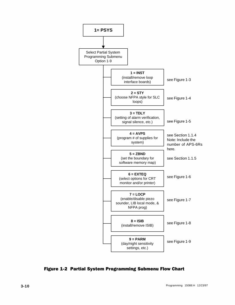
3-10 Programming 15088:H 12/23/97
1= PSYS
Select Partial SystemProgramming Submenu
Option 1-9
1 = INST(install/remove loop
interface boards)
2 = STY(choose NFPA style for SLC
loops)
3 = TDLY(setting of alarm verification,
signal silence, etc.)
4 = AVPS(program # of supplies for
system)
5 = ZBND(set the boundary for
software memory map)
6 = EXTEQ(select options for CRTmonitor and/or printer)
7 = LOCP(enable/disable piezo
sounder, LIB local mode, &NFPA prog)
8 = ISIB(install/remove ISIB)
9 = PARM(day/night sensitivity
settings, etc.)
Figure 1-2 Partial System Programming Submenu Flow Chart
see Figure 1-3
see Figure 1-4
see Figure 1-5
see Section 1.1.4Note: Include thenumber of APS-6Rshere.
see Section 1.1.5
see Figure 1-6
see Figure 1-7
see Figure 1-8
see Figure 1-9
Programming 15088:H 12/23/97 3-11
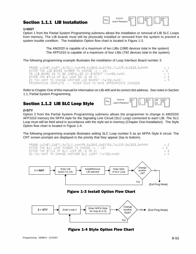
Section 1.1.1 LIB Installation D }X1X1X1=INSTOption 1 from the Partial System Programming submenu allows the installation or removal of LIB SLC Loopsfrom memory. The LIB boards must still be physically installed or removed from the system to prevent asystem trouble condition. The Installation Option flow chart is located in Figure 1-3.
The AM2020 is capable of a maximum of ten LIBs (1980 devices total in the system)The AFP1010 is capable of a maximum of four LIBs (792 devices total in the system)
The following programming example illustrates the installation of Loop Interface Board number 3.
PRESS@1=INST,2=STY,3=TDLY,4=AVPS,5=ZBND,6=EXTEQ,7=LOCP,8=ISIB,9=PARM@@@@@@@@@:@1ENTER@THE@LIB@BOARD@NUMBER@TO@CHANGE@(1@-@10)@@@@@@@@@@@@@@@@@@@@@@@@@@@@@@@:@3IS@LIB@BOARD@03@TO@BE@INSTALLED@IN@SYSTEM?@(Y=YES,N=NO)@@@@@@@@@@@@@@@@@@@@@@:@YENTER@THE@STYLE@OF@SLC@LOOP@03@(6@OR@4)@@@@@@@@@@@@@@@@@@@@@@@@@@@@@@@@@@@@@@:@6DO@YOU@WANT@TO@CHANGE@ANOTHER@LIB@BOARD?@(Y=YES,N=NO)@@@@@@@@@@@@@@@@@@@@@@@@:@N@@PROGRAMMING@COMPLETE@@-@@POWER@DOWN@TO@MAKE@APPROPRIATE@CHANGES
Section 1.1.2 LIB SLC Loop Style D }X1X2X2=STYOption 2 from the Partial System Programming submenu allows the programmer to change in AM2020/AFP1010 memory the NFPA style for the Signaling Line Circuit (SLC Loop) connected to each LIB. The SLCLoop must still be field wired in accordance with the style set in memory (Chapter One-Installation). The StyleOption flow chart is located in Figure 1-4.
The following programming example illustrates setting SLC Loop number 5 as an NFPA Style 6 circuit. TheCRT screen prompts are displayed in the priority that they appear (top to bottom).
PRESS@1=INST,2=STY,3=TDLY,4=AVPS,5=ZBND,6=EXTEQ,7=LOCP,8=ISIB,9=PARM@@@@@@@@@:@2ENTER@THE@SLC@LOOP@NUMBER@TO@CHANGE@(1@-@10)@@@@@@@@@@@@@@@@@@@@@@@@@@@@@@@@:@5ENTER@THE@STYLE@OF@SLC@LOOP@05@(6@OR@4)@@@@@@@@@@@@@@@@@@@@@@@@@@@@@@@@@@@@@@:@6DO@YOU@WANT@TO@CHANGE@ANOTHER@SLC@LOOP?@(Y=YES,N=N0)@@@@@@@@@@@@@@@@@@@@@@@@@:@N
Figure 1-4 Style Option Flow Chart
Refer to Chapter One of this manual for information on LIB-400 and its correct slot address. See notes in Section1.1, Partial System Programming.
Figure 1-3 Install Option Flow Chart
1 = INST Enter LIBboard # (1-10)
Enter Styleof SLC Loop
Install/RemoveLIB selected
Changeanother
LIB?
Yes(Exit Prog Mode)
No
(Exit Prog Mode)2 = STY Enter Loop #Enter NFPA Stylefor loop (6 or 4)
ChangeAnotherStyle?
Yes
No
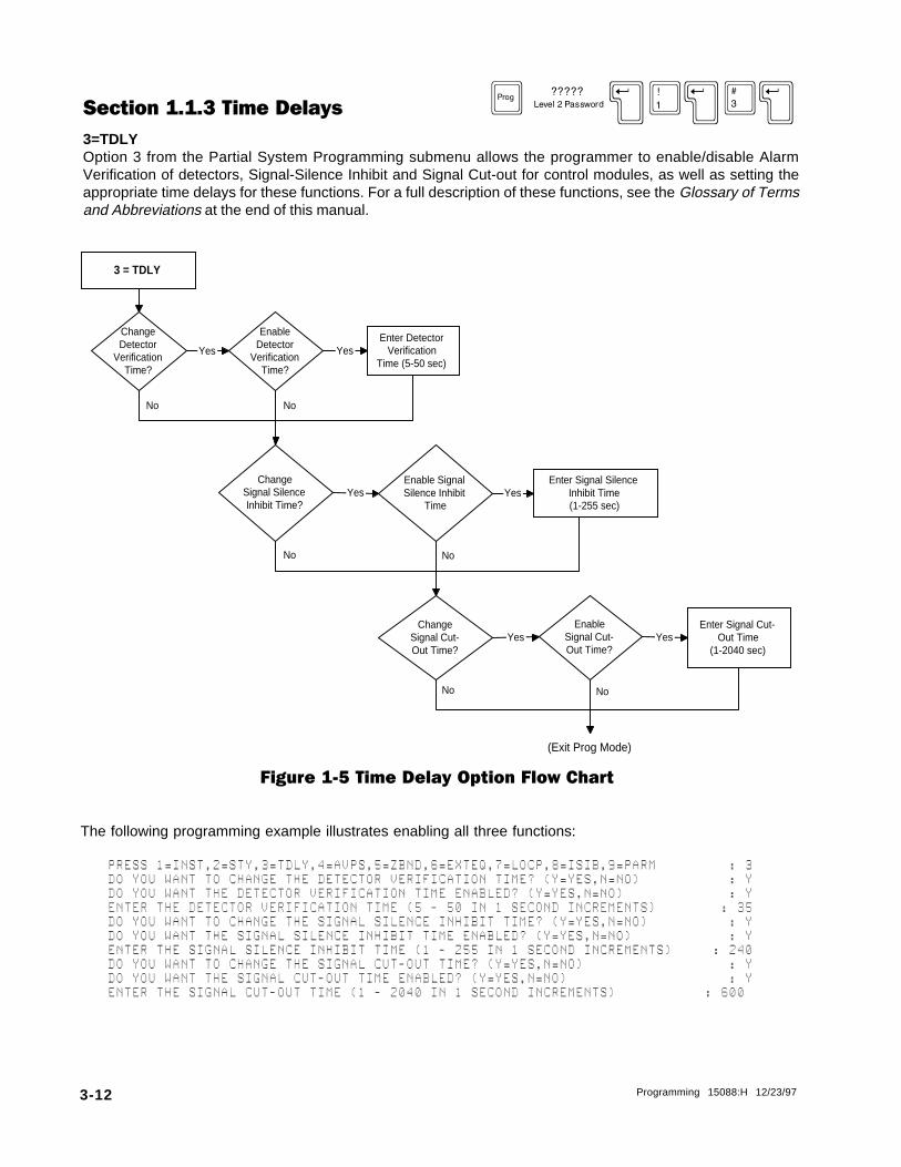
3-12 Programming 15088:H 12/23/97
ChangeDetector
VerificationTime?
ChangeSignal SilenceInhibit Time?
EnableDetector
VerificationTime?
Enable SignalSilence Inhibit
Time
ChangeSignal Cut-Out Time?
EnableSignal Cut-Out Time?
Enter DetectorVerification
Time (5-50 sec)
Enter Signal SilenceInhibit Time(1-255 sec)
Enter Signal Cut-Out Time
(1-2040 sec)
Yes Yes
Yes Yes
Yes Yes
3 = TDLY
(Exit Prog Mode)
No
No No
No
NoNo
Figure 1-5 Time Delay Option Flow Chart
The following programming example illustrates enabling all three functions:
PRESS@1=INST,2=STY,3=TDLY,4=AVPS,5=ZBND,6=EXTEQ,7=LOCP,8=ISIB,9=PARM@@@@@@@@@:@3DO@YOU@WANT@TO@CHANGE@THE@DETECTOR@VERIFICATION@TIME?@(Y=YES,N=NO)@@@@@@@@@@@:@YDO@YOU@WANT@THE@DETECTOR@VERIFICATION@TIME@ENABLED?@(Y=YES,N=NO)@@@@@@@@@@@@@:@YENTER@THE@DETECTOR@VERIFICATION@TIME@(5@-@50@IN@1@SECOND@INCREMENTS)@@@@@@@@:@35DO@YOU@WANT@TO@CHANGE@THE@SIGNAL@SILENCE@INHIBIT@TIME?@(Y=YES,N=NO)@@@@@@@@@@:@YDO@YOU@WANT@THE@SIGNAL@SILENCE@INHIBIT@TIME@ENABLED?@(Y=YES,N=NO)@@@@@@@@@@@@:@YENTER@THE@SIGNAL@SILENCE@INHIBIT@TIME@(1@-@255@IN@1@SECOND@INCREMENTS)@@@@@:@240DO@YOU@WANT@TO@CHANGE@THE@SIGNAL@CUT-OUT@TIME?@(Y=YES,N=NO)@@@@@@@@@@@@@@@@@@:@YDO@YOU@WANT@THE@SIGNAL@CUT-OUT@TIME@ENABLED?@(Y=YES,N=NO)@@@@@@@@@@@@@@@@@@@@:@YENTER@THE@SIGNAL@CUT-OUT@TIME@(1@-@2040@IN@1@SECOND@INCREMENTS)@@@@@@@@@@@:@600
Section 1.1.3 Time Delays D }X1X3X3=TDLYOption 3 from the Partial System Programming submenu allows the programmer to enable/disable AlarmVerification of detectors, Signal-Silence Inhibit and Signal Cut-out for control modules, as well as setting theappropriate time delays for these functions. For a full description of these functions, see the Glossary of Termsand Abbreviations at the end of this manual.

Programming 15088:H 12/23/97 3-13
General ConsiderationsThe capability of the control panel to provide the functions of Alarm Verification, Signal Cut-out, and Signal-Silence Inhibit can be enabled/disabled by the programmer in both Full and Partial System Programming.However, to make use of these functions, the Signal Silence option (for silenceable control modules) and theAlarm Verification option (for addressable detectors) must still be enabled/disabled individually for each SLCLoop device under Full or Partial Point Programming.
For instance, when programming Alarm Verification:
• Under Full or Partial System Programming, the programmer turns Alarm Verification ON and sets theverification time period.
• Under Full or Partial Point Programming, the programmer individually selects Alarm Verification for eachdetector:
Detector 1 = YESDetector 2 = NODetector 3 = YESDetector 4 = YESand so forth for each detector in the system.
Section 1.1.4 Power Supplies D }X1X4X4=AVPSThe number of Audio Visual Power Supplies (AVPS-24/AVPS-24E) and Auxiliary Power Supplies (APS-6R) in thesystem can be programmed into memory by selecting option 4 from the Partial System Programming submenu.The supplies must be physically installed and connected to P5 on the CPU to prevent creating a system troublecondition. The example below illustrates the software installation of two AVPS, one AVPS and one APS-6R, ortwo APS-6R power supplies.
PRESS@1=INST,2=STY,3=TDLY,4=AVPS,5=ZBND,6=EXTEQ,7=LOCP,8=ISIB,9=PARM@@@@@@@@@:@4ENTER@THE@NUMBER@OF@AVPS-24@INSTALLED@IN@THE@SYSTEM@(0@-@16)@@@@@@@@@@@@@@@@:@2
Section 1.1.5 Zone Boundary D }X1X5X5=ZBNDThe AM2020/AFP1010 can make use of up to 240 software-defined “zones.” These zones can be eitherforward–activated (FZON) or reverse–activated (RZON), depending upon the particular installationrequirements. These forward and reverse zones must be grouped separately, with the forward group alwayspreceding the reverse group. The highest forward-activated zone in the system is the Zone Boundary, whichmust be in the range of Z001 - Z239. For a full description of Forward and Reverse Activating Software Zone,see the Glossary of Terms and Abbreviations at the end of this manual.
Unless the use of complex Control-By-Event or Cooperative Control-By-Event Equations is required in thesystem, set the Zone Boundary to Z200 (default). (For more information, see Control-By-Event Programmingand Cooperative Control-By-Event Programming).
The following programming example illustrates setting the Zone Boundary for zone 200.
PRESS@1=INST,2=STY,3=TDLY,4=AVPS,5=ZBND,6=EXTEQ,7=LOCP,8=ISIB,9=PARM@@@@@@@@@:@5ENTER@ZXXX@OF@HIGHEST@FORWARD@ACTIVATED@ZONE@IN@SYSTEM@@@@@@@@@@@@@@@@@@@@:@Z200
Z001 Zone Boundary Z240
Forward Zones Reverse Zones

3-14 Programming 15088:H 12/23/97
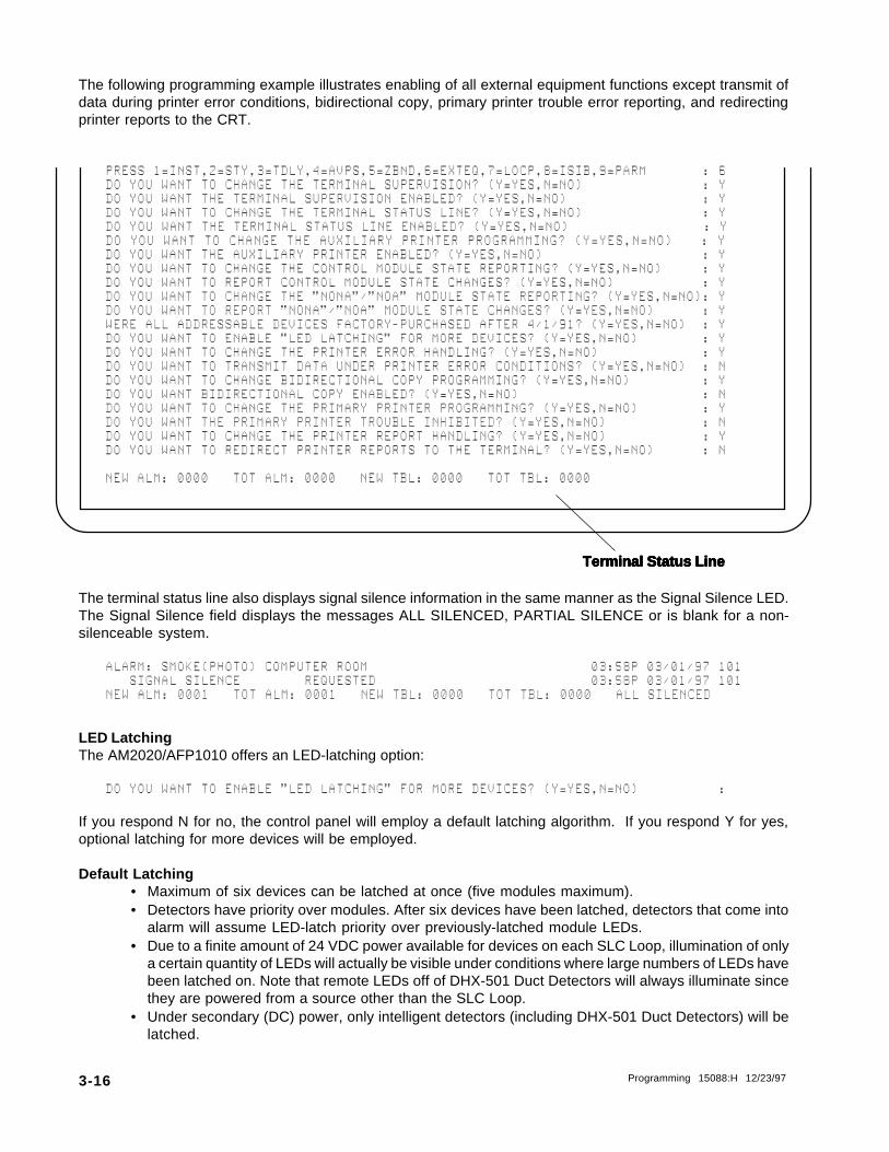
Section 1.1.6 External Equipment D }X1X6X6=EXTEQOption 6 from the Partial System Programming Menu allows the changing of any optional features associatedwith the CRT Monitor or Printer(s).
Terminal Supervision - Electrical supervision of the CRT Monitor. Unless terminal supervi-sion is selected, the CRT will not beep (i.e., no bell characters will besent) when unacknowledged troubles or unacknowledged alarmsare present.
Terminal Status Line - The bottom line of the CRT will display the number of unacknowl-edged alarms and troubles, and the total number of alarms andtroubles in the system. The Terminal Status Line appears on theCRT display only.
Auxiliary Printer Monitoring - The AM2020/AFP1010 will monitor the auxiliary printer's Ready/Busy line for error conditions. Note: The P40 is a special internal 40-column printer. This option should not be enabled for external 80-column printers.
Control Module Reporting - Control module state changes will be printed out.
NONA/NOA Module Reporting - Module state changes for modules with the software type ID NONAor NOA will be printed out. See Software Type IDs for further infor-mation on all software type IDs.
LED LATCH - Enables 99-device LED latching. See restrictions under LED Latch-ing.
Printer Error Continue - Data will be transmitted to the printer under Printer Error conditions(Paper Out or Printer Off Line generates an error condition underwhich data may be lost). Enable for special applications only (seethe CGAS II/AMNET II Manual).
Bidirectional Copy - The CRT will process data received through its AUX port. Enablefor special applications only (see the CGAS II/AMNET II manual andthe CCM-1 Product Installation Document).
Printer Trouble Inhibit - The AM2020/AFP1010 monitors the primary printer's Rx line for er-ror conditions. This option inhibits the generation of a trouble mes-sage for Paper Out or Printer Off Line. Enable for special applica-tions only (see the VGAS Installation manual).
Printer Reports Redirected to CRT- System reports will be echoed to the CRT interface. Enable for spe-cial applications only (see the VGAS Installation Manual and theNAM-232 For Use With AM2020/AFP1010 Manual, Document50424).
The External Equipment Option flow chart is located in Figure 1-6.

Programming 15088:H 12/23/97 3-15
Figure 1-6 External Equipment Option Flow Chart
6 = EXTEQ
Change
Terminal
Supervision?
Enable/Disable
Terminal Supervision
Change
Terminal Status
Line?
Enable/Disable
Terminal Status Line
Yes
Yes
No
Change Aux
Printer Prog?
Enable/Disable Aux
Printer
Yes
No
Change Control
Module State
Reporting?
No
Enable/Disable Aux
PrinterYes
Change NONA/
NOA Module State
Reporting?
No
Enable/Disable
NONA/NOA State
Reporting
Yes
No
Enable/Disable LED
Latching
Yes
Change Printer
Error Handling?
No
Enable/Disable Data
Transmit During
Printer Error
Yes
Change
Bidirectional
Copy?
Enable/Disable
Bidirectional Copy
Yes
No
No
Change Primary
Printer Prog?
Enable/Disable
Primary Printer
Trouble
Yes
Change Printer
Report Handling?
Enable/Disable
Printer Reports
Redirected to CRT
Yes
No
No
(Exit Prog Mode)
All devices
purchased after
4/1/91?
3-16 Programming 15088:H 12/23/97
Terminal Status LineTerminal Status LineTerminal Status LineTerminal Status LineTerminal Status Line
The following programming example illustrates enabling of all external equipment functions except transmit ofdata during printer error conditions, bidirectional copy, primary printer trouble error reporting, and redirectingprinter reports to the CRT.
PRESS@1=INST,2=STY,3=TDLY,4=AVPS,5=ZBND,6=EXTEQ,7=LOCP,8=ISIB,9=PARM@@@@@@@:@6DO@YOU@WANT@TO@CHANGE@THE@TERMINAL@SUPERVISION?@(Y=YES,N=NO)@@@@@@@@@@@@@@@:@YDO@YOU@WANT@THE@TERMINAL@SUPERVISION@ENABLED?@(Y=YES,N=NO)@@@@@@@@@@@@@@@@@:@YDO@YOU@WANT@TO@CHANGE@THE@TERMINAL@STATUS@LINE?@(Y=YES,N=NO)@@@@@@@@@@@@@@@:@YDO@YOU@WANT@THE@TERMINAL@STATUS@LINE@ENABLED?@(Y=YES,N=NO)@@@@@@@@@@@@@@@@ @:@YDO@YOU@WANT@TO@CHANGE@THE@AUXILIARY@PRINTER@PROGRAMMING?@(Y=YES,N=NO) :@YDO@YOU@WANT@THE@AUXILIARY@PRINTER@ENABLED?@(Y=YES,N=NO)@@@@@@@@@@@@@@@@@@@@:@YDO@YOU@WANT@TO@CHANGE@THE@CONTROL@MODULE@STATE@REPORTING?@(Y=YES,N=NO)@@@@@:@YDO@YOU@WANT@TO@REPORT@CONTROL@MODULE@STATE@CHANGES?@(Y=YES,N=NO)@@@@@@@@@@@:@YDO@YOU@WANT@TO@CHANGE@THE@"NONA"/"NOA"@MODULE@STATE@REPORTING?@(Y=YES,N=NO):@YDO@YOU@WANT@TO@REPORT@"NONA"/"NOA"@MODULE@STATE@CHANGES?@(Y=YES,N=NO)@@@@@@:@YWERE@ALL@ADDRESSABLE@DEVICES@FACTORY-PURCHASED@AFTER@4/1/91?@(Y=YES,N=NO)@@:@YDO@YOU@WANT@TO@ENABLE@"LED@LATCHING"@FOR@MORE@DEVICES?@(Y=YES,N=NO)@@@@@@@@:@YDO@YOU@WANT@TO@CHANGE@THE@PRINTER@ERROR@HANDLING?@(Y=YES,N=NO)@@@@@@@@@@@@@:@YDO@YOU@WANT@TO@TRANSMIT@DATA@UNDER@PRINTER@ERROR@CONDITIONS?@(Y=YES,N=NO)@@:@NDO@YOU@WANT@TO@CHANGE@BIDIRECTIONAL@COPY@PROGRAMMING?@(Y=YES,N=NO)@@@@@@@@@:@YDO@YOU@WANT@BIDIRECTIONAL@COPY@ENABLED?@(Y=YES,N=NO)@@@@@@@@@@@@@@@@@@@@@@@:@NDO@YOU@WANT@TO@CHANGE@THE@PRIMARY@PRINTER@PROGRAMMING?@(Y=YES,N=NO)@@@@@@@@:@YDO@YOU@WANT@THE@PRIMARY@PRINTER@TROUBLE@INHIBITED?@(Y=YES,N=NO)@@@@@@@@@@@@:@NDO@YOU@WANT@TO@CHANGE@THE@PRINTER@REPORT@HANDLING?@(Y=YES,N=NO)@@@@@@@@@@@@:@YDO@YOU@WANT@TO@REDIRECT@PRINTER@REPORTS@TO@THE@TERMINAL?@(Y=YES,N=NO)@@@@@@:@N
NEW@ALM:@0000@@@TOT@ALM:@0000@@@NEW@TBL:@0000@@@TOT@TBL:@0000
The terminal status line also displays signal silence information in the same manner as the Signal Silence LED.The Signal Silence field displays the messages ALL SILENCED, PARTIAL SILENCE or is blank for a non-silenceable system.
ALARM:@SMOKE(PHOTO)@COMPUTER@ROOM@@@@@@@@@@@@@@@@@@@@@@@@@@@@03:58P@03/01/97@101@@@SIGNAL@SILENCE@@@@@@@@REQUESTED@@@@@@@@@@@@@@@@@@@@@@@@@@@03:58P@03/01/97@101NEW@ALM:@0001@@@TOT@ALM:@0001@@@NEW@TBL:@0000@@@TOT@TBL:@0000@@@ALL@SILENCED
LED LatchingThe AM2020/AFP1010 offers an LED-latching option:
DO@YOU@WANT@TO@ENABLE@"LED@LATCHING"@FOR@MORE@DEVICES?@(Y=YES,N=NO)@@@@@@@@@@:
If you respond N for no, the control panel will employ a default latching algorithm. If you respond Y for yes,optional latching for more devices will be employed.
Default Latching• Maximum of six devices can be latched at once (five modules maximum).• Detectors have priority over modules. After six devices have been latched, detectors that come into
alarm will assume LED-latch priority over previously-latched module LEDs.• Due to a finite amount of 24 VDC power available for devices on each SLC Loop, illumination of only
a certain quantity of LEDs will actually be visible under conditions where large numbers of LEDs havebeen latched on. Note that remote LEDs off of DHX-501 Duct Detectors will always illuminate sincethey are powered from a source other than the SLC Loop.
• Under secondary (DC) power, only intelligent detectors (including DHX-501 Duct Detectors) will belatched.

Programming 15088:H 12/23/97 3-17
Optional Latching for More Devices• The control panel will latch up to 99 devices, subject to the limitations outlined below.• All devices in the system must be of the R4 variety (see below).• No RA-400 Remote LEDs can be installed on any device, excluding the DHX-501 Duct Detectors.• Due to a finite amount of 24 VDC power available for devices on each SLC Loop, illumination of only
a certain quantity of LEDs will actually be visible under conditions where large numbers of LEDs havebeen latched on. Note that remote LEDs off of DHX-501 Duct Detectors will always illuminate since theyare powered from a source other than the SLC Loop.
• Under primary (AC) power, 99 devices can be latched.• Detectors have priority over modules. After 99 devices have been latched, detectors that come into
alarm will assume LED-latch priority over previously-latched module LEDs.• Under secondary (DC) power, only intelligent detectors (including DHX-501 Duct Detectors) will be
latched.
MORE LED latching can only be employed if ALL installed addressabledevices were purchased from the Notifier factory after April 1, 1991.Use of this feature under any other circumstances can cause the SLCLoops to shut down. Devices compatible with more LED latching willhave the code R4 stamped on the product marking label. SDX-551/751Photoelectric detectors can also have an H code after the model number.
NOTES• Modules refer to monitor and control modules, and XP Transponder circuits. Devices are defined as
intelligent detectors and modules.• Software Type I.D.s PWRC, NCMN, SCON and NOA will never latch under Default Latching.
3-18 Programming 15088:H 12/23/97
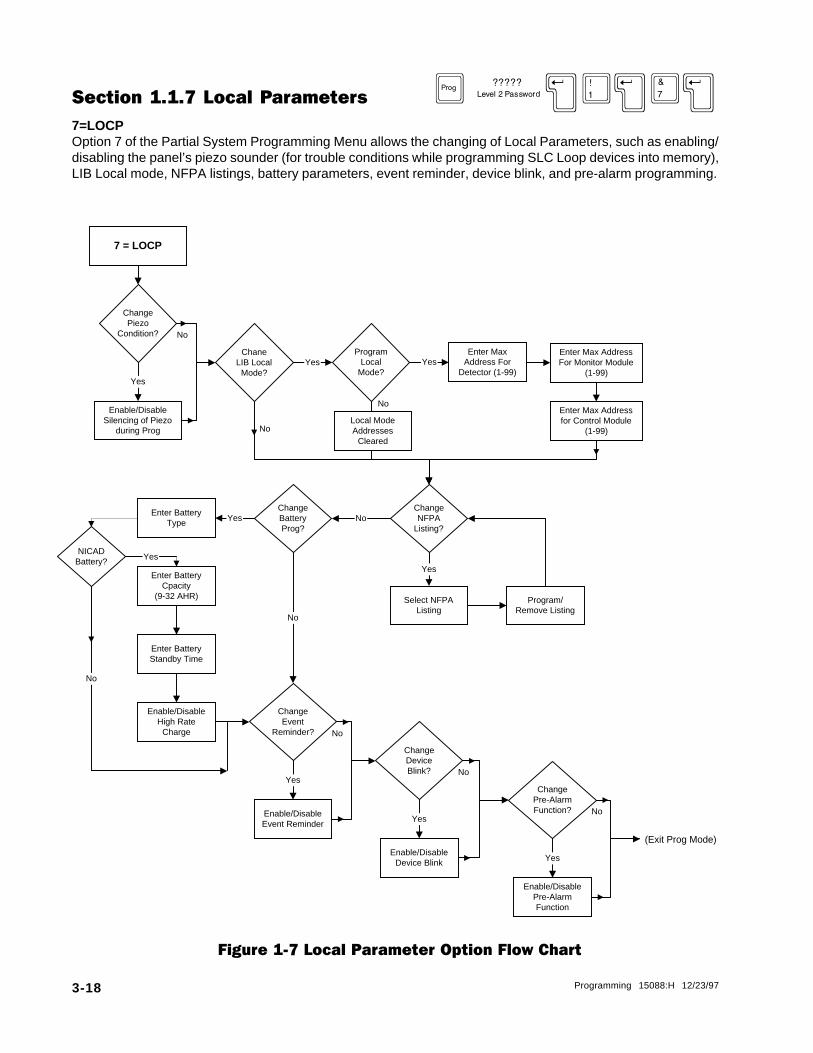
Figure 1-7 Local Parameter Option Flow Chart
Section 1.1.7 Local Parameters D }X1X7X7=LOCPOption 7 of the Partial System Programming Menu allows the changing of Local Parameters, such as enabling/disabling the panel’s piezo sounder (for trouble conditions while programming SLC Loop devices into memory),LIB Local mode, NFPA listings, battery parameters, event reminder, device blink, and pre-alarm programming.
ChangePiezo
Condition?
ChaneLIB Local
Mode?
Enable/DisableSilencing of Piezo
during Prog
Enter Max Addressfor Control Module
(1-99)
ProgramLocal
Mode?
Enter MaxAddress For
Detector (1-99)Yes
Enter Max AddressFor Monitor Module
(1-99)
ChangeNFPA
Listing?
Select NFPAListing
Program/Remove Listing
Yes
NoChangeBatteryProg?
Yes Yes
Enter BatteryType Yes
7 = LOCP
Enter BatteryCpacity
(9-32 AHR)
Enter BatteryStandby Time
ChangeEvent
Reminder?
Enable/DisableEvent Reminder
ChangeDeviceBlink?
Enable/DisableDevice Blink
Yes
Yes
No
(Exit Prog Mode)
Enable/DisableHigh Rate
Charge
No
No
No
No
No
NICADBattery? Yes
No
Local ModeAddresses
Cleared
ChangePre-AlarmFunction?
Enable/DisablePre-AlarmFunction
Yes
No

Programming 15088:H 12/23/97 3-19
The following programming example illustrates the disabling of the panel’s piezo sounder, programming LIBLocal mode, modifying NFPA listings, programming the battery parameters, changing the event reminder,device blink and pre-alarm programming.
NOTEThe sounder must be enabled upon completion of programming!
PRESS@1=INST,2=STY,3=TDLY,4=AVPS,5=ZBND,6=EXTEQ,7=LOCP,8=ISIB,9=PARM@@@:@7DO@YOU@WANT@TO@CHANGE@THE@PIEZO@TROUBLE@CONDITION?@(Y=YES,N=NO)@@@@@@@@:@YDO@YOU@WANT@THE@PIEZO@SOUNDER@SILENCED@WHILE@PROGRAMMING?@(Y=YES,N=NO)@:@YDO@YOU@WANT@TO@CHANGE@THE@LIB@LOCAL@MODE@PARAMETERS?@(Y=YES,N=NO)@@@@@@:@YDO@YOU@WANT@TO@PROGRAM@LOCAL@MODE?@(Y=YES,N=NO)@@@@@@@@@@@@@@@@@@@@@@@@:@YENTER@MAXIMUM@ADDRESS@FOR@DETECTOR@LOCAL@MODE@(1@-@99)@@@@@@@@@@@@@@@@:@99ENTER@MAXIMUM@ADDRESS@FOR@MONITOR@MODULE@LOCAL@MODE@(1@-@99)@@@@@@@@@@:@99ENTER@MAXIMUM@ADDRESS@FOR@CONTROL@MODULE@LOCAL@MODE@(1@-@99)@@@@@@@@@@:@99DO@YOU@WANT@TO@MODIFY@NFPA@LISTINGS?@(Y=YES,N=NO)@@@@@@@@@@@@@@@@@@@@@@:@YSELECT@NFPA@LISTING@-@1=72A,2=72B,3=72C,4=72D,5=71,6=RCV@@@@@@@@@@@@@@@:@1DO@YOU@WANT@TO@PROGRAM@OR@REMOVE@THIS@LISTING?@(Y=PRG,N=RMV)@@@@@@@@@@@:@YDO@YOU@WANT@TO@MODIFY@NFPA@LISTINGS?@(Y=YES,N=NO)@@@@@@@@@@@@@@@@@@@@@@:@YSELECT@NFPA@LISTING@-@1=72A,2=72B,3=72C,4=72D,5=71,6=RCV@@@@@@@@@@@@@@@:@2DO@YOU@WANT@TO@PROGRAM@OR@REMOVE@THIS@LISTING?@(Y=PRG,N=RMV)@@@@@@@@@@@:@YDO@YOU@WANT@TO@MODIFY@NFPA@LISTINGS?@(Y=YES,N=NO)@@@@@@@@@@@@@@@@@@@@@@:@NDO@YOU@WANT@TO@CHANGE@THE@BATTERY@PROGRAMMING?@(Y=YES,N=NO)@@@@@@@@@@@@:@YENTER@THE@TYPE@OF@BATTERY@INSTALLED@(L=LEAD-ACID,N=NICAD)@@@@@@@@@@@@@@:@NDO@YOU@WANT@TO@CHANGE@THE@BATTERY@CAPACITY?@(Y=YES,N=NO)@@@@@@@@@@@@@@@:@YENTER@THE@BATTERY@CAPACITY@(9@-@32@IN@1@AHR@INCREMENTS)@@@@@@@@@@@@@@@:@12DO@YOU@WANT@TO@CHANGE@THE@BATTERY@STANDBY@TIME?@(Y=YES,N=NO)@@@@@@@@@@@:@YENTER@THE@BATTERY@STANDBY@TIME@(4,@24,@48@OR@60@HR)@@@@@@@@@@@@@@@@@@@:@48DO@YOU@WANT@24@HOUR@HIGH@RATE@CHARGE@FOR@BATTERY?@(Y=YES,N=NO)@@@@@@@@@:@YDO@YOU@WANT@TO@CHANGE@THE@EVENT@REMINDER@PROGRAMMING?@(Y=YES,N=NO)@@@@@:@YDO@YOU@WANT@THE@EVENT@REMINDER@ENABLED?@(Y=YES,N=NO)@@@@@@@@@@@@@@@@@@@:@YDO@YOU@WANT@TO@CHANGE@THE@DEVICE@BLINK?@(Y=YES,N=NO)@@@@@@@@@@@@@@@@@@@:@YDO@YOU@WANT@THE@DEVICE@BLINK@ENABLED?@(Y=YES,N=NO)@@@@@@@@@@@@@@@@@@@@@:@YDO@YOU@WANT@TO@CHANGE@THE@PRE-ALARM@FUNCTION?@(Y=YES,N=NO)@@@@@@@@@@@@@:@YDO@YOU@WANT@THE@PRE-ALARM@FUNCTION@ENABLED?@(Y=YES,N=NO)@@@@@@@@@@@@@@@:@Y
General Operation of the Piezo Sounder• The piezo sounder provides feedback each time a key is pressed on the DIA.
• The piezo sounder sounds for unacknowledged alarm conditions.
• The piezo sounder sounds steadily for unacknowledged trouble or supervisory conditions.
• The piezo sounder chirps periodically (approximately every 12 seconds) for acknowledgedconditions remaining in the system upon selection of the Event Reminder option.

3-20 Programming 15088:H 12/23/97
Local Mode OperationLocal mode operation allows the LIB-200, LIB-200A, and LIB-400 boards to run independently of the CPU ifCPU to LIB communications should fail.
All LIB boards use the same control-by-event, with the following format:
IF Any intelligent detector with an address less than or equal to the maximum detectorlocal mode address is in alarm.
AND/OR Any monitor module with an address less than or equal to the maximum monitor mod-ule local mode address is in alarm.
THEN All control modules with an address less than or equal to the maximum control mod-ule local mode address will be activated.
Extended Local Mode OperationDevices local to each individual LIB are divided into local mode categories based on Software Type I.D.s. Alldevices within the local mode address range will participate in local mode. Below is a description of each localmode category and a table showing which device types reside in each category. For complete definitions ofSoftware Type I.D.s, refer to Section Three, Software Type I.D.s.
Table 1-1 Extended Local Mode Categories and Software Type I.D.s
1 2 3 4 5 6 7 8 9 A B
TOHP BRTM USPS TAW NOC DNPT ELET DNPA SFW CSS CRWP
NOI GAPM RPUS RKPS DNPG EGAP AGVE CFW
REHT AON CROF CTG SAG
NOM MRAS SXMC SRT CAG
LLUP MYSS CXMC CRT
RHTF MCAS MCRF TCAD
TAW MQES
NOCSYROGETAC NOITPIRCSED
llamuminimataneht,evitcaemoceb1yrogetaCnisecivedgnitatitinidradnatsgnitapicitrapehtfoynafI1saetavitcayamsecivedgnitacidnirehto(detavitcaeblliw5yrogetaCnisecivedgnitacidnignitapicitrap
).noitavitcaecivedgnitaitinidradnatsfotceffeedisa
.secivedrehtorofstceffeedisonevahdnaedomlacolybnodetcarevenerasecivedgnitaitiniesehT2
.etavitcalliwCSS.D.IepyT,evitcaemocebsecivedgnitaitiniesehtfI3
.etavitcalliwCFWdnaSFWs.D.IepyT,evitcaemocebsecivedgnitaitiniesehtfI4
gnitapicitrapllaneht,evitcaemoceb1yrogetaCnisecivedgnitaitinidradnatsgnitapicitrapehtfoynafI5.evitcaemoceb5yrogetaCnisecivedgnitacidnidradnats
.evitcasyawlaerasecivedgnitacidniesehtedomlacolgniruD6
.edomlacolnietapicitrapyehtfietavitcalliwsecivedgnitacidniesehT7
.evitcasitupnimralagnitapicitrapnonrognitapicitrapynafietavitcalliwsecivedgnitacidniesehT8
.evitcasiTAW.D.IepyThtiweludomgnitaitiniynafietavitcalliwsecivedgnitacidniesehT9
.evitcasiRPUSroUSPS.D.IepyThtiweludomgnitaitiniynafietavitcalliwsecivedgnitacidniesehTA
-lasecivedlanoitnevnocotrewopevomerottesermetsysnopuyliraropmetetavitcaedsecivedesehTBserotmehtgniwol .te
NMCN
ANON
THPF
LUPM
DNOI
HNOI
LNOI
OBMC

Programming 15088:H 12/23/97 3-21
NFPA ListingsNFPA listing allows the programmer to change the operation of the panel based on the NFPA listings selected.Each listing will select one or more mandatory modules.
Listing Software ID Address
* NFPA 72-1993 (72A) Local Fire Alarm Systems EVGA L1M96
NFPA 72-1993 (72B) Auxiliary Fire Alarm Systems GAS L1M97
** NFPA 72-1993 (72C) Remote Station Fire Alarm Systems GAC L1M98GAC L1M99
** NFPA 72-1993 (72D) Proprietary Fire Alarm Systems n/a n/a
** NFPA 72-1993 (71) Central Station Fire Alarm Systems n/a n/a
Receiving Unit (RCV) and Central Station Unit n/a n/a
* Fire alarm input devices automatically default to latching operation when the 72A listing is selected.** NFPA 72-1993 (72C), (72D), and (71) are no longer required and should not be selected during
programming.
Once a module is programmed by an NFPA Listing selection, that module can only be removed from the systemby de-selection of that same listing. Selection of RCV disables the block acknowledge function. RCV must beenabled for all Central Station Receiving and Proprietary and Protected Premises receiving units. RCV is notsupported by NOTI�FIRE�NET�NOTI�FIRE�NET�NOTI�FIRE�NET�NOTI�FIRE�NET�NOTI�FIRE�NET� systems that contain an NRT or AFP-200 panel.
NOTES• Modules must be connected on the LIB SLC Loop with the appropriate address(es) set in order
to avoid trouble conditions.• NFPA modules selected must be in their normal state or acknowledged prior to de-selection
otherwise trouble conditions may not clear from the panel memory.
Pre-Alarm FunctionThe pre-alarm function causes the FACP to generate a trouble message when the chamber value of the detectorhas exceeded 80% of the alarm threshold (determined by the sensitivity selection of low, medium, high).
• With pre-alarm enabled, the 80% condition must be present for at least a 60 second period and willindicate a "PRE-ALARM ALERT" message on the FACP after that period.
• With pre-alarm disabled the 80% condition must be present for at least a 26 hour period and will indicatea "MAINTENANCE REQ" message on the FACP after that period.
NOTEThis condition (detector exceeding 80% of alarm threshold) may be due to a dirty detector. Thedetector should be inspected and cleaned as necessary by an authorized service representative.Failure to do so may result in a false alarm.
3-22 Programming 15088:H 12/23/97
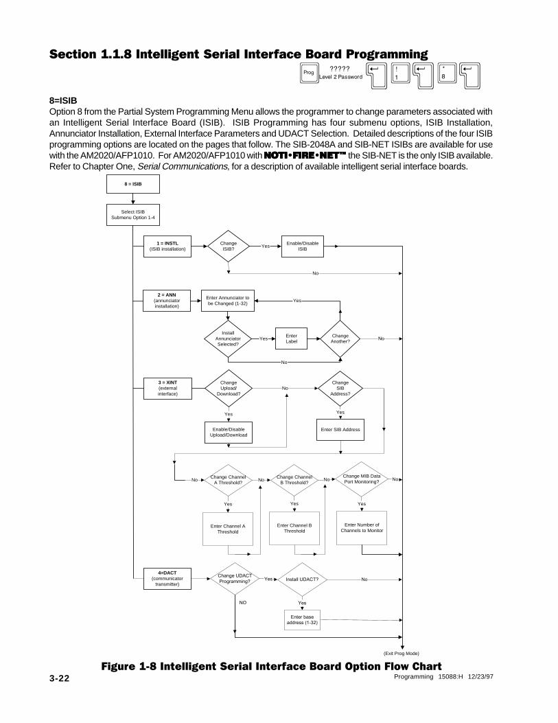
Section 1.1.8 Intelligent Serial Interface Board Programming
D }X1X8X8=ISIBOption 8 from the Partial System Programming Menu allows the programmer to change parameters associated withan Intelligent Serial Interface Board (ISIB). ISIB Programming has four submenu options, ISIB Installation,Annunciator Installation, External Interface Parameters and UDACT Selection. Detailed descriptions of the four ISIBprogramming options are located on the pages that follow. The SIB-2048A and SIB-NET ISIBs are available for usewith the AM2020/AFP1010. For AM2020/AFP1010 with NOTI�FIRE�NET�NOTI�FIRE�NET�NOTI�FIRE�NET�NOTI�FIRE�NET�NOTI�FIRE�NET� the SIB-NET is the only ISIB available.Refer to Chapter One, Serial Communications, for a description of available intelligent serial interface boards.
Figure 1-8 Intelligent Serial Interface Board Option Flow Chart
8 = ISIB
ChangeISIB?
Select ISIBSubmenu Option 1-4
2 = ANN(annunciatorinstallation)
1 = INSTL(ISIB installation)
Enter Annunciator tobe Changed (1-32)
InstallAnnunciatorSelected?
Enable/DisableISIB
EnterLabel
ChangeAnother?
Yes
Yes
Yes
(Exit Prog Mode)
No
No
Yes Yes
ChangeUpload/
Download?
ChangeSIB
Address?
3 = XINT(externalinterface)
Enable/DisableUpload/Download
Enter SIB Address
No
Change ChannelA Threshold?
Change ChannelB Threshold?
Change MIB DataPort Monitoring?No No No
Enter Channel AThreshold
Yes
Enter Channel BThreshold
Yes
Enter Number ofChannels to Monitor
Yes
No
4=DACT(communicator
transmitter)
Change UDACT
Programming?Yes Install UDACT?
Enter base
address (1-32)
Yes
No
NO
No

Programming 15088:H 12/23/97 3-23
After entering option 8 from the Partial System Programming submenu, the display will show the ISIB submenu:
PRESS@1=INSTL,2=ANN,3=XINT,4=DACT @@@@@@@@@@@@@@@@@@@@ @@@@@@@@@@@@@@@@@@ :
1=INSTL - ISIB Installation D }X1X8X1XThis option allows the installation or removal of the Intelligent Serial Interface Board from control panelmemory. The board must still be physically installed or removed from the system to prevent a system troublecondition. The following programming example illustrates the installation of the Intelligent Serial InterfaceBoard.
PRESS@1=INSTL,2=ANN,3=XINT,4=DACT@@@@@@@@@@@@@@@@@@@@@@@@@@@@@@@@@@@@@@ :@1DO@YOU@WANT@TO@CHANGE@THE@INTELLIGENT@SIB?@(Y=YES,N=NO)@@@@@@@@@@@@@@@@ :@YDO@YOU@WANT@THE@INTELLIGENT@SIB@ENABLED?@(Y=YES,N=NO)@@@@@@@@@@@@@@@@@@ :@YPROGRAMMING@COMPLETE@@-@@POWER@DOWN@TO@MAKE@APPROPRIATE@CHANGES
2=ANN - Annunciator Installation D }X1X8X2XThis option allows the installation or removal of annunciators (EIA-485 devices) from the AM2020/AFP1010memory. The modules must still be physically installed or removed from the system to prevent a systemtrouble condition. The following programming example illustrates the installation of annunciator module 1.
PRESS@1=INSTL,2=ANN,3=XINT,4=DACT :@2ENTER@THE@ANNUNCIATOR@NUMBER@TO@CHANGE@(1@-@32) :@1IS@ANNUNCIATOR@01@TO@BE@INSTALLED@IN@SYSTEM?@(Y=YES,N=NO) :@YENTER@20@CHARACTER@CUSTOM@LABEL :@ANNUNCIATOR@ONEDO@YOU@WANT@TO@CHANGE@ANOTHER@ANNUNCIATOR?@(Y=YES,N=NO) :@NPROGRAMMING@COMPLETE@@-@@POWER@DOWN@TO@MAKE@APPROPRIATE@CHANGES
* The SCS-8 and SCS-8L firmware has been updated in conjunction with Software Release 2.8. The new SCSfirmware is not backward compatible with older revisions of software.
3=XINT - External Interface Parameters D }X1X8X3XThis option allows the programmer to change the parameters associated with the external interface port.The following example illustrates enabling all associated parameters.
PRESS@1=INSTL,2=ANN,3=XINT,4=DACT :@3DO@YOU@WANT@TO@CHANGE@THE@ACS PORT@UPLOAD/DOWNLOAD?@(Y=YES,N=NO) :@YDO@YOU@WANT@THE@ACS PORT@UPLOAD/DOWNLOAD@ENABLED?@(Y=YES,N=NO) :@YDO@YOU@WANT@TO@CHANGE@THE@INTELLIGENT@SIB@ADDRESS?@(Y=YES,N=NO) :@YENTER@THE@INTELLIGENT@SIB@ADDRESS@(0@-@249) :@249DO@YOU@WANT@TO@CHANGE@THE@MIB-W@THRESHOLD@FOR@CHANNEL@A?@(Y=YES,N=NO):@YENTER@THE@MIB-W@VALUE@THRESHOLD@FOR@CHANNEL@A@(H=HIGH,L=LOW) :@LDO@YOU@WANT@TO@CHANGE@THE@MIB-W@THRESHOLD@FOR@CHANNEL@B?@(Y=YES,N=NO):@YENTER@THE@MIB-W@VALUE@THRESHOLD@FOR@CHANNEL@B@(H=HIGH,L=LOW) :@HDO@YOU@WANT@TO@CHANGE@MIB@DATA@PORT@USAGE?@(Y=YES,N=NO) :@YDO@YOU@WANT@TO@USE@BOTH@MIB@DATA@PORTS?@(Y=YES,N=NO) :@Y
* These items are NOTI�FIRE�NET�NOTI�FIRE�NET�NOTI�FIRE�NET�NOTI�FIRE�NET�NOTI�FIRE�NET� specific functions and are only programmed when a SIB-NET is used.
NOTES• During an upload/download, the fire protection capability of the AM2020/AFP1010 is enabled (it is
limited for download). To reduce the risk of incompatible databases, the programmer shouldNEVER program any parameters into the control panel while an upload/download is in progress.
• To communicate over the external interface, the annunciator modules MUST first be disconnectedsince both functions use the same serial port.
See notes in Section 1.1, Partial System Programming.
********

3-24 Programming 15088:H 12/23/97
4=DACT - UDACT Installation D }X1X8X4XThis option allows the installer to program a Notifier UDACT (Universal Digital Alarm CommunicatorTransmitter) and specify its base annunciator protocol address in the system. The example below illustratesprogramming a UDACT.
Before programming a UDACT into an AM2020/AFP1010 system, the number of annunciator addressesrequired must be determined. First, take the number of annunciator points in the system and add 8 points (forthe UDACT). Then, divide the total by 64 to obtain the number of annunciator addresses required (round up tonext whole number if decimal).
PRESS 1=INSTL,2=ANN,3=XINT,4=DACT :@4
DO YOU WANT TO CHANGE THE UDACT PROGRAMMING?@(Y=YES,N=NO) :@YDO YOU WANT A UDACT INSTALLED? (Y=YES,N=NO) :@YENTER THE BASE ADDRESS FOR UDACT OPERATION (1@-@32)@@@@@@@@@@@@@ :@1
NOTES• The UDACT can only be programmed into or removed from the system through the Partial System
Programming Menu.
• The UDACT must be programmed at an installed annunciator address. Once programmed, the first 8annunciator protocol points (base address only) automatically become unique fire panel statusindicators (see UDACT Manual). These 8 functions required by the UDACT override any previousAM2020/AFP1010 annunciator point programming. When a UDACT is installed, the first 8 AM2020/AFP1010 annunciator points associated with the UDACT base address cannot be reprogrammed/removed and have no read status functionality.
• Answering "NO" for the question, "Do you want a UDACT installed?" disables the automatic 8 pointUDACT programming and restores these points to their original annunciator point programming.
• Multiple annunciator addresses may need to be programmed depending upon the range specified bythe UDACT annunciator address switches.
• The UDACT cannot be used in systems containing an AVPS-24/AVPS-24E, AA-30/AA-30E, AA-120,AA-120E or XP Transponder since a primary power failure signal transmission will not be delayed asrequired for this application.
• When using the UDACT in a system with a NIB-96, use care to ensure that the EIA-485 addressesselected do not overlap with those of the NIB-96.
• When a UDACT is programmed into the system, both the red and yellow LEDs will illuminate on anannunciator point mapped to a supervisory input during the presence of a supervisory signal for thatpoint, unless the supervisory ACS reporting option has been enabled.
• Off-premises transmission of security alarms using the UDACT must be made by mapping inputpoints with the software type ID "SACM" and "SEQM" to annunciator points within the range of theUDACT. Use of other security type IDs for this purpose will result in simultaneous transmissionof a trouble signal.
• Multiple UDACT usage per AM2020/AFP1010 system is not permitted.

Programming 15088:H 12/23/97 3-25
9 = PARM
ChangeHigh Day/
NightZone?
ChangeLow Day/
NightZone?
Enter Zone # tobe set High
Enter Zone# to be Set
Low
Yes
No
EnableHigh
Zone?Yes
No*No
EnableLow Zone? Yes
ChangeDetector
VerificationTrouble
Counter?
EnableDetector
VerificationTrouble?
Enter DetectorVerification
Trouble Count (1-20)
Change DriftCompensation
?
Enable/DisableSACM/SEQM
State ReportingYes
ChangeSACM/SEQMModule StateReporting?
Enable/DisableDrift
CompensationYes
(Exit Prog Mode)
No
No
ChangePager Prog?
Enable/DisablePagerYes
No
ChangeModemProg?
Enable/DisableModemYes
No
ChangeNAM Prog?
Enable/DisableNAM
Yes
No
ChangeRapidPollingProg?
Enable/DisableRapid PollingYes
No
No No
Yes
Yes Yes
No*
ChangeSupervisory
ACSReporting?
EnableSupervisory
ACSReporting?
Yes
No
* Zone Cleared
Section 1.1.9 Additional System Parameters D }X1X9X9=PARMThis option allows the programmer to enable/disable additional system parameters such as the day/nightsensitivity of detectors or rapid polling. For a full description of these functions, see the Glossary of Terms andAbbreviations at the end of this manual.
Figure 1-9 Additional System Parameters Option Flow Chart

3-26 Programming 15088:H 12/23/97
The following programming example illustrates enabling these functions.
PRESS@1=INST,2=STY,3=TDLY,4=AVPS,5=ZBND,6=EXTEQ,7=LOCP,8=ISIB,9=PARM :@9DO@YOU@WANT@TO@CHANGE@THE@HIGH@DAY/NIGHT@SENSITIVITY@ZONE?@(Y=YES,N=NO) :@YDO@YOU@WANT@A@HIGH@DAY/NIGHT@SENSITIVITY@ZONE?@(Y=YES,N=NO) :@YENTER@HIGH@DAY/NIGHT@SENSITIVITY@ZONE@(ZXXX) :@Z150DO@YOU@WANT@TO@CHANGE@THE@LOW@DAY/NIGHT@SENSITIVITY@ZONE?@(Y=YES,N=NO) :@YDO@YOU@WANT@A@LOW@DAY/NIGHT@SENSITIVITY@ZONE?@(Y=YES,N=NO) :@YENTER@LOW@DAY/NIGHT@SENSITIVITY@ZONE@(ZXXX) :@Z1DO@YOU@WANT@TO@CHANGE@THE@ DETECTOR@ VER.@TROUBLE @COUNTER?@(Y=YES,N=NO) :@YDO@YOU@WANT@THE@ DETECTOR@ VERIFICATION @TROUBLE @ENABLED?@(Y=YES,N=NO) :@YENTER@DETECTOR@ VERIFICATION @TROUBLE@ COUNT@(1@-@20) :@15DO@YOU@WANT@TO@CHANGE@"SACM"/"SEQM"@MODULE@STATE@REPORTING?@(Y=YES,N=NO) :@YDO@YOU@WANT@TO@REPORT@"SACM"/"SEQM"@MODULE@STATE@CHANGES?@(Y=YES,N=NO) :@YDO@YOU@WANT@TO@CHANGE@THE@DRIFT@COMPENSATION@OPERATION?@(Y=YES,N=NO) :@YDO@YOU@WANT@DRIFT@COMPENSATION@ENABLED?@(Y=YES,N=NO) :@YDO@YOU@WANT@TO@CHANGE@THE@PAGER@PROGRAMMING?@(Y=YES,N=NO) :@YDO@YOU@WANT@THE@PAGER@ENABLED?@(Y=YES,N=NO) :@YDO@YOU@WANT@TO@CHANGE@THE@MODEM@PROGRAMMING?@(Y=YES,N=NO) :@YDO@YOU@WANT@THE@MODEM@ENABLED?@(Y=YES,N=NO) :@YDO@YOU@WANT@TO@CHANGE@THE@NAM@PROGRAMMING?@(Y=YES,N=NO) :@YDO@YOU@WANT@THE@NAM@ENABLED?@(Y=YES,N=NO) :@NDO@YOU@WANT@TO@CHANGE@THE@RAPID@POLLING@PROGRAMMING?@(Y=YES,N=NO) :@YDO@YOU@WANT@RAPID@POLLING@ENABLED?@(Y=YES,N=NO) :@YDO @YOU @WANT @TO@ CHANGE@ THE @SUPERVISORY@ MODULE@ ACS @REPORTING?@ (Y=YES,N=NO) :@YDO@ YOU@ WANT@ SUPERVISORY@ MODULES @TO@ ILLUMINATE@ ACTIVE @LED?@ (Y=YES,N=NO) :@Y
Day/Night SensitivityThe function of Day/Night sensitivity is to force intelligent detectors into high or low sensitivity when theappropriate zones are active, regardless of the detectors normal sensitivity setting. If both the high and lowzones are active, the system is forced to high sensitivity. The Day/Night high and low sensitivity zones maybe individually activated by control-by-event (CBE) equations written for this purpose or through the use ofcontrol-by-time equations.
The capability of the control panel to provide the function of day/night sensitivity can be enabled/disabled inboth Full and Partial System Programming. However, the day/night sensitivity option (for addressabledetectors) must be enabled/disabled individually for each SLC Loop device.
The following must be performed when programming Day/Night Detector Sensitivity:
• Enable the Day/Night Sensitivity and set the zone number. This is a global setting.• Select Day/Night Sensitivity for each individual detector. For example:
Detector 1 = YESDetector 2 = NODetector 3 = YESDetector 4 = YES
Detector Verification TroubleIf set, the control panel will generate a trouble for each intelligent detector which exceeds the verificationcounter trouble limit. This feature can be used to isolate those devices which excessively go into detectorverification before causing false alarm conditions in the panel. To clear this condtion reset the detector verificationcounters as described in Section 2.6.
SACM/SEQM Module ReportingIf selected for reporting, module state changes for modules with the software type ID SACM or SEQM will beprinted out. See Software Type IDs for further information on all software type IDs.
Drift CompensationIf set, the addressable detectors will automatically compensate for environmental contaminants and otherfactors over time, until the drift tolerance value has been exceeded. When the drift tolerance value has beenexceeded, the control panel will signal a maintenance alert for the apropriate detector.

Programming 15088:H 12/23/97 3-27
PagerThe Pager mode must be enabled when a compatible pager is connected to the auxiliary printer port.
ModemIf enabled, the following remote device (CRT) functions are inhibited: ACK STEP, SIGNAL SILENCE, SYSTEMRESET, PROGRAMMING, and ALTER STATUS. This option must be employed when a modem is used toreceive signals from an off-premise device. See the TPI-232 manual.
NAMThe NAM-232 is used to tie a remote FACP to the NOTI�FIRE�NET� via telephone lines. If the NAM isenabled, the following options are automatically programmed as indicated:
• Terminal Supervision = Enabled• Terminal Status Line = Enabled• Receiving Unit Mode = Enabled• Event Reminder = Disabled• Reports Redirected to Terminal = Enabled• Modem = Disabled
This special application only supports the ACKNOWLEDGE, SIGNAL SILENCE, and SYSTEM RESETnetwork functions and is intended for Protected Premises Fire Alarm System (Local) use only. Local use of aCRT, printer or other 232 device from the remote FACP is prohibited. No other system network functions canbe implemented due to system contraints. For more information refer to the NAM-232 for Use With AM2020/AFP1010 Manual, Document 50424.
Rapid PollingThe AM2020/AFP1010 has the option to utilize a rapid polling algorithm to process certain monitor modules ona priority basis. When used properly, this can result in a much faster response from fire alarm call points (pullstations) and security devices. If Rapid Polling is enabled, the first 20 module addresses on each LIB SLCloop are polled more frequently than the other addresses and should be used for high priority input deviceswhen using this feature. XPM-8 circuits and output devices (CMX and XPC-8 circuits) should not be assignedaddresses in the rapid polling range.
Supervisory Module ACS ReportingIf selected for reporting, activation of modules with the software type ID SUPR or SPSU will cause the primary(top) LED to light instead of the secondary (bottom) LED for an ACS Annunciator Point.

3-28 Programming 15088:H 12/23/97
PRESS@1=PSYS,2=FSYS,3=PPRG,4=FPRG,5=REMV,6=PSWD,7=MSG,8=HIS@@@@@@@@@@@@@@@:@2IS@LIB@BOARD@01@TO@BE@INSTALLED@IN@SYSTEM?@@@@@@@@@@@@@@@@@@@@@@@@@@@@@@@@:@YENTER@THE@STYLE@OF@SLC@LOOP@01@(6@OR@4)@@@@@@@@@@@@@@@@@@@@@@@@@@@@@@@@@@@:@6IS@LIB@BOARD@02@TO@BE@INSTALLED@IN@SYSTEM?@@@@@@@@@@@@@@@@@@@@@@@@@@@@@@@@:@YENTER@THE@STYLE@OF@SLC@LOOP@02@(6@OR@4)@@@@@@@@@@@@@@@@@@@@@@@@@@@@@@@@@@@:@4IS@LIB@BOARD@03@TO@BE@INSTALLED@IN@@SYSTEM?@@@@@@@@@@@@@@@@@@@@@@@@@@@@@@@:@YENTER@THE@STYLE@OF@SLC@LOOP@03@(6@OR@4)@@@@@@@@@@@@@@@@@@@@@@@@@@@@@@@@@@@:@6IS@LIB@BOARD@04@TO@BE@INSTALLED@IN@SYSTEM?@@@@@@@@@@@@@@@@@@@@@@@@@@@@@@@@:@NIS@LIB@BOARD@05@TO@BE@INSTALLED@IN@SYSTEM?@@@@@@@@@@@@@@@@@@@@@@@@@@@@@@@@:@NIS@LIB@BOARD@06@TO@BE@INSTALLED@IN@SYSTEM?@@@@@@@@@@@@@@@@@@@@@@@@@@@@@@@@:@NIS@LIB@BOARD@07@TO@BE@INSTALLED@IN@SYSTEM?@@@@@@@@@@@@@@@@@@@@@@@@@@@@@@@@:@NIS@LIB@BOARD@08@TO@BE@INSTALLED@IN@SYSTEM?@@@@@@@@@@@@@@@@@@@@@@@@@@@@@@@@:@NIS@LIB@BOARD@09@TO@BE@INSTALLED@IN@SYSTEM?@@@@@@@@@@@@@@@@@@@@@@@@@@@@@@@@:@NIS@LIB@BOARD@10@TO@BE@INSTALLED@IN@SYSTEM?@@@@@@@@@@@@@@@@@@@@@@@@@@@@@@@@:@NDO@YOU@WANT@THE@DETECTOR@VERIFICATION@TIME@ENABLED?@(Y=YES,N=NO)@@@@@@@@@@:@YENTER@THE@DETECTOR@VERIFICATION@TIME@(5@-@50@IN@1@SECOND@INCREMENTS)@@@@@:@45DO@YOU@WANT@THE@SIGNAL@SILENCE@INHIBIT@TIME@ENABLED?@(Y=YES,N=NO)@@@@@@@@@:@YENTER@THE@SIGNAL@SILENCE@INHIBIT@TIME@(1@-@255@IN@1@SECOND@INCREMENTS)@@:@60DO@YOU@WANT@THE@SIGNAL@CUT-OUT@TIME@ENABLED?@(Y=YES,N=NO)@@@@@@@@@@@@@@@@@:@YENTER@THE@SIGNAL@CUT-OUT@TIME@(1@-@2040@IN@1@SECOND@INCREMENTS)@@@@@@@@:@1200ENTER@THE@NUMBER@OF@AVPS-24@INSTALLED@IN@THE@SYSTEM@(0@-@16)@@@@@@@@@@@@@@:@4ENTER@ZXXX@OF@HIGHEST@FORWARD@ACTIVATED@ZONE@IN@SYSTEM@@@@@@@@@@@@@@@@@:@Z200DO@YOU@WANT@THE@TERMINAL@SUPERVISION@ENABLED?@(Y=YES,N=NO)@@@@@@@@@@@@@@@@:@YDO@YOU@WANT@THE@TERMINAL@STATUS@LINE@ENABLED?@(Y=YES,N=NO)@@@@@@@@@@@@@@@@:@YDO@YOU@WANT@THE@AUXILIARY@PRINTER@ENABLED?@(Y=YES,N=NO)@@@@@@@@@@@@@@@@@@@:@YDO@YOU@WANT@TO@REPORT@CONTROL@MODULE@STATE@CHANGES?@(Y=YES,N=NO)@@@@@@@@@@:@YDO@YOU@WANT@TO@REPORT@"NONA"/"NOA"@MODULE@STATE@CHANGES?@(Y=YES,N=NO)@@@@@:@YWERE@ALL@ADDRESSABLE@DEVICES@FACTORY-PURCHASED@AFTER@4/1/91?@(Y=YES,N=NO)@:@YDO@YOU@WANT@TO@ENABLE@"LED@LATCHING"@FOR@MORE@DEVICES?@(Y=YES,N=NO)@@@@@@@:@YDO@YOU@WANT@TO@TRANSMIT@DATA@UNDER@PRINTER@ERROR@CONDITIONS?@(Y=YES,N=NO)@:@NDO@YOU@WANT@BIDIRECTIONAL@COPY@ENABLED?@(Y=YES,N=NO)@@@@@@@@@@@@@@@@@@@@@@:@YDO@YOU@WANT@THE@PRIMARY@PRINTER@TROUBLE@INHIBITED?@(Y=YES,N=NO)@@@@@@@@@@@:@YDO@YOU@WANT@TO@REDIRECT@PRINTER@REPORTS@TO@THE@TERMINAL?@(Y=YES,N=NO)@@@@@:@NDO@YOU@WANT@TO@PROGRAM@LOCAL@MODE?@(Y=YES,N=NO)@@@@@@@@@@@@@@@@@@@@@@@@@@@:@YENTER@MAXIMUM@ADDRESS@FOR@DETECTOR@LOCAL@MODE@(1@-@99)@@@@@@@@@@@@@@@@@@@:@45ENTER@MAXIMUM@ADDRESS@FOR@MONITOR@MODULE@LOCAL@MODE@(1@-@99)@@@@@@@@@@@@@:@26ENTER@MAXIMUM@ADDRESS@FOR@CONTROL@MODULE@LOCAL@MODE@(1@-@99)@@@@@@@@@@@@@:@19DO@YOU@WANT@TO@MODIFY@NFPA@LISTINGS?@(Y=YES,N=NO)@@@@@@@@@@@@@@@@@@@@@@@@@:@YSELECT@NFPA@LISTING@-@1=72A,2=72B,3=72C,4=72D,5=71,6=RCV@@@@@@@@@@@@@@@@@@:@1DO@YOU@WANT@TO@PROGRAM@OR@REMOVE@THIS@LISTING?@(Y=PRG,N=RMV)@@@@@@@@@@@@@@:@YDO@YOU@WANT@TO@MODIFY@NFPA@LISTINGS?@(Y=YES,N=NO)@@@@@@@@@@@@@@@@@@@@@@@@@:@YSELECT@NFPA@LISTING@-@1=72A,2=72B,3=72C,4=72D,5=71,6=RCV@@@@@@@@@@@@@@@@@@:@2DO@YOU@WANT@TO@PROGRAM@OR@REMOVE@THIS@LISTING?@(Y=PRG,N=RMV)@@@@@@@@@@@@@@:@YDO@YOU@WANT@TO@MODIFY@NFPA@LISTINGS?@(Y=YES,N=NO)@@@@@@@@@@@@@@@@@@@@@@@@@:@NENTER@THE@TYPE@OF@BATTERY@INSTALLED@(L=LEAD-ACID,N=NICAD)@@@@@@@@@@@@@@@@@:@NENTER@THE@BATTERY@CAPACITY@(9@-@32@IN@1@AHR@INCREMENTS)@@@@@@@@@@@@@@@@@@:@32ENTER@THE@BATTERY@STANDBY@TIME@(4,@24,@48@OR@60@HR)@@@@@@@@@@@@@@@@@@@@@@:@4DO@YOU@WANT@24@HOUR@HIGH@RATE@CHARGE@FOR@BATTERY?@(Y=YES,N=NO)@@@@@@@@@@@@:@Y
Section 1.2 Full System Programming D }X2X2=FSYSOption 2 from the Programming Menu walks the programmer through complete initial programming of system-widefunctions. Alarm Verification, Signal-Silence Inhibit, Signal Cut-Out, and the supervision of peripherals are allprogrammed under this option, as well as the number of AVPS, APS-6R, LIBs, ISIB and Annunciator Modules inthe system, and SLC Loop styles. The following CRT display illustrates the screen prompts during the installationof three SLC loops, four Annunciator Modules and the enabling of all optional functions. Refer to Chapter One ofthis manual for information on LIB-400 and its correct slot address.
For information on the parameters programmed here, refer to Partial System Programming.
AM
2020
only
Includenumber ofAPS-6Rhere
Programming 15088:H 12/23/97 3-29
DO@YOU@WANT@THE@EVENT@REMINDER@ENABLED?@(Y=YES,N=NO)@@@@@@@@@@@@@@@@@@@@@:@YDO@YOU@WANT@THE@DEVICE@BLINK@ENABLED?@(Y=YES,N=NO)@@@@@@@@@@@@@@@@@@@@@@@:@YDO@YOU@WANT@THE@PRE-ALARM@FUNCTION@ENABLED?@(Y=YES,N=NO)@@@@@@@@@@@@@@@@@:@YDO@YOU@WANT@THE@INTELLIGENT@SIB@ENABLED?@(Y=YES,N=NO)@@@@@@@@@@@@@@@@@@@@:@YIS@ANNUNCIATOR@01@TO@BE@INSTALLED@IN@SYSTEM?@(Y=YES,N=NO)@@@@@@@@@@@@@@@@:@YENTER@20@CHARACTER@CUSTOM@LABEL@@@@@@@@@@@@@@@@@@@@@@@@@@@:@ANNUNCIATOR@1IS@ANNUNCIATOR@02@TO@BE@INSTALLED@IN@SYSTEM?@(Y=YES,N=NO)@@@@@@@@@@@@@@@@:@NIS@ANNUNCIATOR@04@TO@BE@INSTALLED@IN@SYSTEM?@(Y=YES,N=NO)@@@@@@@@@@@@@@@@:@NIS@ANNUNCIATOR@05@TO@BE@INSTALLED@IN@SYSTEM?@(Y=YES,N=NO)@@@@@@@@@@@@@@@@:@NIS@ANNUNCIATOR@06@TO@BE@INSTALLED@IN@SYSTEM?@(Y=YES,N=NO)@@@@@@@@@@@@@@@@:@NIS@ANNUNCIATOR@07@TO@BE@INSTALLED@IN@SYSTEM?@(Y=YES,N=NO)@@@@@@@@@@@@@@@@:@NIS@ANNUNCIATOR@08@TO@BE@INSTALLED@IN@SYSTEM?@(Y=YES,N=NO)@@@@@@@@@@@@@@@@:@NIS@ANNUNCIATOR@09@TO@BE@INSTALLED@IN@SYSTEM?@(Y=YES,N=NO)@@@@@@@@@@@@@@@@:@NIS@ANNUNCIATOR@10@TO@BE@INSTALLED@IN@SYSTEM?@(Y=YES,N=NO)@@@@@@@@@@@@@@@@:@NIS@ANNUNCIATOR@11@TO@BE@INSTALLED@IN@SYSTEM?@(Y=YES,N=NO)@@@@@@@@@@@@@@@@:@NIS@ANNUNCIATOR@12@TO@BE@INSTALLED@IN@SYSTEM?@(Y=YES,N=NO)@@@@@@@@@@@@@@@@:@YENTER@20@CHARACTER@CUSTOM@LABEL@@@@@@@@@@@@@@@@@@@@@@@@@@@:@ANNUNCIATOR@12IS@ANNUNCIATOR@13@TO@BE@INSTALLED@IN@SYSTEM?@(Y=YES,N=NO)@@@@@@@@@@@@@@@@:@NIS@ANNUNCIATOR@14@TO@BE@INSTALLED@IN@SYSTEM?@(Y=YES,N=NO)@@@@@@@@@@@@@@@@:@NIS@ANNUNCIATOR@15@TO@BE@INSTALLED@IN@SYSTEM?@(Y=YES,N=NO)@@@@@@@@@@@@@@@@:@NIS@ANNUNCIATOR@16@TO@BE@INSTALLED@IN@SYSTEM?@(Y=YES,N=NO)@@@@@@@@@@@@@@@@:@NIS@ANNUNCIATOR@17@TO@BE@INSTALLED@IN@SYSTEM?@(Y=YES,N=NO)@@@@@@@@@@@@@@@@:@NIS@ANNUNCIATOR@18@TO@BE@INSTALLED@IN@SYSTEM?@(Y=YES,N=NO)@@@@@@@@@@@@@@@@:@YENTER@20@CHARACTER@CUSTOM@LABEL@@@@@@@@@@@@@@@@@@@@@@@@@@@:@ANNUNCIATOR@18IS@ANNUNCIATOR@19@TO@BE@INSTALLED@IN@SYSTEM?@(Y=YES,N=NO)@@@@@@@@@@@@@@@@:@NIS@ANNUNCIATOR@20@TO@BE@INSTALLED@IN@SYSTEM?@(Y=YES,N=NO)@@@@@@@@@@@@@@@@:@NIS@ANNUNCIATOR@21@TO@BE@INSTALLED@IN@SYSTEM?@(Y=YES,N=NO)@@@@@@@@@@@@@@@@:@NIS@ANNUNCIATOR@22@TO@BE@INSTALLED@IN@SYSTEM?@(Y=YES,N=NO)@@@@@@@@@@@@@@@@:@NIS@ANNUNCIATOR@23@TO@BE@INSTALLED@IN@SYSTEM?@(Y=YES,N=NO)@@@@@@@@@@@@@@@@:@NIS@ANNUNCIATOR@24@TO@BE@INSTALLED@IN@SYSTEM?@(Y=YES,N=NO)@@@@@@@@@@@@@@@@:@NIS@ANNUNCIATOR@25@TO@BE@INSTALLED@IN@SYSTEM?@(Y=YES,N=NO)@@@@@@@@@@@@@@@@:@NIS@ANNUNCIATOR@26@TO@BE@INSTALLED@IN@SYSTEM?@(Y=YES,N=NO)@@@@@@@@@@@@@@@@:@NIS@ANNUNCIATOR@27@TO@BE@INSTALLED@IN@SYSTEM?@(Y=YES,N=NO)@@@@@@@@@@@@@@@@:@NIS@ANNUNCIATOR@28@TO@BE@INSTALLED@IN@SYSTEM?@(Y=YES,N=NO)@@@@@@@@@@@@@@@@:@NIS@ANNUNCIATOR@29@TO@BE@INSTALLED@IN@SYSTEM?@(Y=YES,N=NO)@@@@@@@@@@@@@@@@:@NIS@ANNUNCIATOR@30@TO@BE@INSTALLED@IN@SYSTEM?@(Y=YES,N=NO)@@@@@@@@@@@@@@@@:@NIS@ANNUNCIATOR@31@TO@BE@INSTALLED@IN@SYSTEM?@(Y=YES,N=NO)@@@@@@@@@@@@@@@@:@YENTER@20@CHARACTER@CUSTOM@LABEL@@@@@@@@@@@@@@@@@@@@@@@@@@@:@ANNUNCIATOR@31IS@ANNUNCIATOR@32@TO@BE@INSTALLED@IN@SYSTEM?@(Y=YES,N=NO)@@@@@@@@@@@@@@@@:@NENTER@THE@INTELLIGENT@SIB@ADDRESS@(0@-@249)@@@@@@@@@@@@@@@@@@@@@@@@@@@@:@160ENTER@THE@MIB-W@VALUE@THRESHOLD@FOR@CHANNEL@A@(H=HIGH,L=LOW)@@@@@@@@@@@@@:@HENTER@THE@MIB-W@VALUE@THRESHOLD@FOR@CHANNEL@B@(H=HIGH,L=LOW)@@@@@@@@@@@@@:@HDO@YOU@WANT@TO@USE@BOTH@MIB@DATA@PORTS?@(Y=YES,N=NO)@@@@@@@@@@@@@@@@@@@@@:@YDO@YOU@WANT@A@HIGH@DAY/NIGHT@SENSITIVITY@ZONE?@(Y=YES,N=NO)@@@@@@@@@@@@@@:@YENTER@HIGH@DAY/NIGHT@SENSITIVITY@ZONE@(ZXXX)@@@@@@@@@@@@@@@@@@@@@@@@@@:@Z200DO@YOU@WANT@A@LOW@DAY/NIGHT@SENSITIVITY@ZONE?@(Y=YES,N=NO)@@@@@@@@@@@@@@@:@YENTER@LOW@DAY/NIGHT@SENSITIVITY@ZONE@(ZXXX)@@@@@@@@@@@@@@@@@@@@@@@@@@@:@Z201DO@ YOU @WANT@ THE @DETECTOR@ VERIFICATION @TROUBLE@ ENABLED?@ (Y=YES,N=NO) @@@@@@:@ YENTER@ DETECTOR @VERIFICATION @TROUBLE @COUNT@ (1@-@20)@@@@@@@@@@@@@@@@@@@@@@:@15DO@YOU@WANT@TO@REPORT@"SACM"/"SEQM"@MODULE@STATE@CHANGES?@(Y=YES,N=NO)@@@:@YDO@YOU@WANT@DRIFT@COMPENSATION@ENABLED?@(Y=YES,N=NO)@@@@@@@@@@@@@@@@@@@@@:@YDO@YOU@WANT@THE@PAGER@ENABLED?@(Y=YES,N=NO)@@@@@@@@@@@@@@@@@@@@@@@@@@@@@@:@YDO@YOU@WANT@THE@MODEM@ENABLED?@(Y=YES,N=NO)@@@@@@@@@@@@@@@@@@@@@@@@@@@@@@:@YDO@YOU@WANT@THE@NAM@ENABLED?@(Y=YES,N=NO)@@@@@@@@@@@@@@@@@@@@@@@@@@@@@@@@:@NDO@YOU@WANT@RAPID@POLLING@ENABLED?@(Y=YES,N=NO)@@@@@@@@@@@@@@@@@@@@@@@@@@:@YDO@YOU@WANT@SUPERVISORY@MODULES@TO@ILLUMINATE@ACTIVE@LED?@(Y=YES,N=NO)@@@:@YPROGRAMMING@COMPLETE@@-@@POWER@DOWN@TO@MAKE@APPROPRIATE@CHANGES
See notes in Section 1.1, Partial System Programming.
****
* These items are NOTI�FIRE�NET�NOTI�FIRE�NET�NOTI�FIRE�NET�NOTI�FIRE�NET�NOTI�FIRE�NET� specific functions and are only programmed when a SIB-NET is used.

3-30 Programming 15088:H 12/23/97
Section 1.3 Partial Point Programming D }X3X3=PPRGOption 3 from the Programming Menu allows the programmer to change the operational parameters of SLC Loopdevices, software-defined zones, and annunciator points.
After selecting option 3 from the Main Programming menu, the display will show the Partial Point Programmingsubmenu:
PRESS@1=TYPID,2=CBE,3=LBL,4=OPTNS,5=AMAP,6=CCBE@@@@@@@@@@@@@@@@@@@@@@@@@@@@@@:
The Partial Point Programming submenu has six options, where:
1=TYPID Type ID - Changing the software type identification of SLC Loop devices, zones andannunciator points.
2=CBE Control-By-Event - Redefining the Control-By-Event associated with each detector,module, or zone.
3=LBL Label - Renaming the custom user label for any detector, module, or zone.
4=OPTNS Options - Selecting the optional features associated with any detector or module.
5=AMAP Annunciator Point Mapping - Selecting Annunciator Point Mapping for any detector,module, or zone.
6=CCBE Cooperative Control-By-Event - Edit the CCBE associated with reverse activatedzones for NOTI�FIRE�NET.
The Partial Point Programming flow chart is located in Figure 1-10. Detailed information on the Partial PointProgramming options follows.
NOTEEach option under Partial Point Programming prompts the programmer to enter the address of thedetector, module, zone, or annunciator point to be affected. Leading zeros are not required. The
address assumes the following format:
LXX(D/M)YY (for devices) or ZXXX (for zones) or AXXPYY (for annunciator points)
Example: For the 44th module on SLC Loop 3, enter L3M44
AnnunciatorModule 1 to 32
AnnunciatorPoint 1 to 64
SLC Loop1 to 10 (AM2020),1 to 4 (AFP1010)
Addressable Detector or Mod-ule followed by an address inthe range 1 to 99
Software-definedZone Z1 to Z240

Programming 15088:H 12/23/97 3-31
3 = PPRG
1 = TYPID(Change device, zone, or annunciator
point software type ID)
3 = LBL(change custom label associated with
each device, and software zone)
4 = OPTNS(enable/disable for each device signalsilence, walk test, alarm verification,
sensitivity, or tracking)
2 = CBE(change CBE list or equation which
controls interaction between devices,and software zones)
5 = AMAP(individually maps devices or softwarezones to annunciator points for remote
annunciation)
Select Partial PointProgramming Submenu
Option 1-6
6 = CCBE(change CCBE equation associated
with reverse activated zones)
Section 1.3.1 Type ID D }X3X1X1=TYPIDOption 1 of the Partial Point Programming Menu allows the programmer to change the Software Type ID ofany detector, module, zone or annunciator point. This pre-setting of all devices in the system gives the controlpanel the ability to execute specific functions for each device type. The following CRT display illustrates theassignment of the Software Type ID SCON to the 14th monitor module on SLC Loop 3.
PRESS@1=TYPID,2=CBE,3=LBL,4=OPTNS,5=AMAP,6=CCBE@@@@@@@@@@@@@@@@@@@@@@@@@@@@@@:@1ENTER@LXX(D/M)YY,@ZXXX@OR@AXXPYY@FOR@PT.@CHANGE@(BCKSPC@TO@ABORT)@@@@@@@:@L3M14ENTER@TYPE@ID@@@@@@@@@@@@@@@@@@@@@@@@@@@@@@@@@@@@@@@@@@@@@@@@@@@@@@@@@@@@@:@SCON@
For a complete description of the various software type IDs, see Software Type IDs.
Figure 1-10 Partial Point Programming Flow Chart
see Section 1.3.1
see Section 1.3.2
see Section 1.3.3
see Figure 1-11
see Figure 1-12
see Section 1.3.6

3-32 Programming 15088:H 12/23/97
Section 1.3.2 Control-By-Event D }X3X2X2=CBEOption 2 of the Partial Point Programming Menu allows the programmer to change the Control-By-Event (CBE)for any detector, module or software zone. The panel maintains a CBE for each device and zone installed inthe system.
NOTEA software zone is not a physical zone, but rather a software grouping in control panel memory.
When programming a particular device, the control panel prompts the programmer with:
ENTER@CONTROL-BY-EVENT@@@@@@@@@@@@@@@@@@@@@@@@@@@@@@@@@@@@@@@@@@@@@@@@@@@@@@@:
The following CRT screen display illustrates CBE programming for smoke detector number 23 on SLC Loop 2to activate software zones 15 and 29.
PRESS@1=TYPID,2=CBE,3=LBL,4=OPTNS,5=AMAP,6=CCBE@@@@@@@@@@@@@@@@@@@@@@@@@@@@:@2ENTER@LXX(D/M)YY,@ZXXX@OR@AXXPYY@FOR@PT.@CHANGE@(BCKSPC@TO@ABORT)@@@@@:@L2D23ENTER@CONTROL-BY-EVENT@@@@@@@@@@@@@@@@@@@@@@@@@@@@@@@@@@@@@@@@@@@@@@@@@@@@@@@:(Z15@Z29)
For a complete description of the types, parameters, limitations, and guidelines of CBE programming, seeControl-By-Event Programming in Section Four.
Section 1.3.3 Label D }X3X3X3=LBLOption 3 of the Partial Point Programming Menu allows the programmer to change the 20-Character CustomLabel associated with each detector, module, or software zone in the system. Acceptable characters fordevice or zone labels are as follows:
Letters A through Z, digits 0 through 9, periods (.), dashes (-), and spaces.
The following CRT display illustrates renaming control module 21 on SLC Loop 1.
PRESS@1=TYPID,2=CBE,3=LBL,4=OPTNS,5=AMAP,6=CCBE@@@@@@@@@@@@@@@@@@@@@@@@@@@@:@3ENTER@LXX(D/M)YY,@ZXXX@OR@AXXPYY@FOR@PT.@CHANGE@(BCKSPC@TO@ABORT)@@@@@:@L1M21ENTER@20@CHARACTER@CUSTOM@LABEL@@@@@@@@@@@@@@@@@@@@@@@@@@@:@MAIN@LOBBY@BELLS@@@
Programming Tip:Creative use of the Label feature allows the programmer to be extremely specific in naming each SLC Loopdevice. For instance, for a group of addressable devices congregated in a particular area (such as a floor or asection of a building), map each device to the same software zone and label the zone to serve as an additional20 characters of information to the individual device labels. Assume Detector 3 initiates an alarm:
ALARM: SMOKE(PHOTO) GUEST KITCHENALARM: SMOKE(PHOTO) GUEST KITCHENALARM: SMOKE(PHOTO) GUEST KITCHENALARM: SMOKE(PHOTO) GUEST KITCHENALARM: SMOKE(PHOTO) GUEST KITCHEN 3RD FLOOR WEST WING 05:48P 03/01/97 103 3RD FLOOR WEST WING 05:48P 03/01/97 103 3RD FLOOR WEST WING 05:48P 03/01/97 103 3RD FLOOR WEST WING 05:48P 03/01/97 103 3RD FLOOR WEST WING 05:48P 03/01/97 103
Detectors 1through 5all mapped tothesame SoftwareZone
Software ZoneD1 D2 D3 D4 D5
Specific locationSpecific locationSpecific locationSpecific locationSpecific location General locationGeneral locationGeneral locationGeneral locationGeneral location
The result is a 40-character label that characterizes a particular addressable device.
Programming 15088:H 12/23/97 3-33
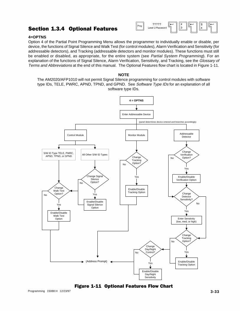
Section 1.3.4 Optional Features D }X3X4X4=OPTNSOption 4 of the Partial Point Programming Menu allows the programmer to individually enable or disable, perdevice, the functions of Signal Silence and Walk Test (for control modules), Alarm Verification and Sensitivity (foraddressable detectors), and Tracking (addressable detectors and monitor modules). These functions must stillbe enabled or disabled, as appropriate, for the entire system (see Partial System Programming). For anexplanation of the functions of Signal Silence, Alarm Verification, Sensitivity, and Tracking, see the Glossary ofTerms and Abbreviations at the end of this manual. The Optional Features flow chart is located in Figure 1-11.
NOTEThe AM2020/AFP1010 will not permit Signal Silence programming for control modules with softwaretype IDs, TELE, PWRC, APND, TPND, and GPND. See Software Type IDs for an explanation of all
software type IDs.
Figure 1-11 Optional Features Flow Chart
Monitor Module AddressableDetector
Control Module
4 = OPTNS
Enter Addressable Device
ChangeDay/NightControl?
ChangeVerification
Option?
Enable/DisableDay/NightSensitivity
Enable/DisableVerification Option
ChangeDetector
Sensitivity?
ChangeTrackingOption?
Enter Senstivity(low, med, or high)
Enable/DisableTracking Option
Yes
Change SignalSilenceOption?
Enable/DisableSignal Silence
Option
ChangeWalk TestOption?
Enable/DisableWalk Test
Option
Yes
ChangeTrackingOption?
Enable/DisableTracking Option
(Address Prompt)
No
Yes
Yes
YesNo
No
No
S/W ID Type TELE, PWRC,APND, TPND, or GPND
All Other S/W ID Types
Yes
No
No
No
(panel determines device entered and branches accordingly)
Yes
3-34 Programming 15088:H 12/23/97
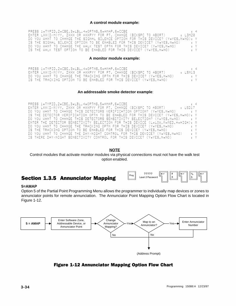
PRESS@1=TYPID,2=CBE,3=LBL,4=OPTNS,5=AMAP,6=CCBE@@@@@@@@@@@@@@@@@@@@@@@@@@@@@@:@4ENTER@LXX(D/M)YY,@ZXXX@OR@AXXPYY@FOR@PT.@CHANGE@(BCKSPC@TO@ABORT)@@@@@@@:@L3M20DO@YOU@WANT@TO@CHANGE@THE@SIGNAL@SILENCE@OPTION@FOR@THIS@DEVICE?@(Y=YES,N=NO):@YIS@THE@SIGNAL@SILENCE@OPTION@TO@BE@ENABLED@FOR@THIS@DEVICE?@(Y=YES,N=NO)@@@@@:@YDO@YOU@WANT@TO@CHANGE@THE@WALK@TEST@OPTN@FOR@THIS@DEVICE?@(Y=YES,N=NO)@@@@@@@:@YIS@THE@WALK@TEST@OPTION@TO@BE@ENABLED@FOR@THIS@DEVICE?@(Y=YES,N=NO)@@@@@@@@@@:@Y
A control module example:
A monitor module example:
PRESS@1=TYPID,2=CBE,3=LBL,4=OPTNS,5=AMAP,6=CCBE@@@@@@@@@@@@@@@@@@@@@@@@@@@@@@:@4ENTER@LXX(D/M)YY,@ZXXX@OR@AXXPYY@FOR@PT.@CHANGE@(BCKSPC@TO@ABORT)@@@@@@@:@L5M13DO@YOU@WANT@TO@CHANGE@THE@TRACKING@OPTN@FOR@THIS@DEVICE?@(Y=YES,N=NO)@@@@@@@@:@YIS@THE@TRACKING@OPTION@TO@BE@ENABLED@FOR@THIS@DEVICE?@(Y=YES,N=NO)@@@@@@@@@@@:@Y
An addressable smoke detector example :
PRESS@1=TYPID,2=CBE,3=LBL,4=OPTNS,5=AMAP,6=CCBE@@@@@@@@@@@@@@@@@@@@@@@@@@@@@@:@4ENTER@LXX(D/M)YY,@ZXXX@OR@AXXPYY@FOR@PT.@CHANGE@(BCKSPC@TO@ABORT)@@@@@@@:@L5D17DO@YOU@WANT@TO@CHANGE@THIS@DETECTORS@VERIFICATION@OPTION?@(Y=YES,N=NO)@@@@@@@:@YIS@THE@DETECTOR@VERIFICATION@OPTN@TO@BE@ENABLED@FOR@THIS@DEVICE?@(Y=YES,N=NO):@YDO@YOU@WANT@TO@CHANGE@THIS@DETECTORS@SENSITIVITY@SELECTION?@(Y=YES,N=NO)@@@@@:@YENTER@THE@DETECTOR@SENSITIVITY@SELECTION@FOR@THIS@DEVICE@(L=LOW,M=MED,H=HIGH):@MDO@YOU@WANT@TO@CHANGE@THE@TRACKING@OPTN@FOR@THIS@DEVICE?@(Y=YES,N=NO)@@@@@@@@:@YIS@THE@TRACKING@OPTION@TO@BE@ENABLED@FOR@THIS@DEVICE?@(Y=YES,N=NO)@@@@@@@@@@@:@YDO@YOU@WANT@TO@CHANGE@THE@DAY/NIGHT@CONTROL@FOR@THIS@DEVICE?@(Y=YES,N=NO)@@@@:@YIS@THERE@DAY/NIGHT@SENSITIVITY@CONTROL@FOR@THIS@DEVICE?@(Y=YES,N=NO)@@@@@@@@@:@Y
NOTEControl modules that activate monitor modules via physical connections must not have the walk test
option enabled.
Section 1.3.5 Annunciator Mapping D }X3X5X5=AMAPOption 5 of the Partial Point Programming Menu allows the programmer to individually map devices or zones toannunciator points for remote annunciation. The Annunciator Point Mapping Option Flow Chart is located inFigure 1-12.
5 = AMAP Map to anAnnunciator?
Enter AnnunciatorNumber
Yes YesEnter Software Zone,
Addressable Device, orAnnunciator Point
(Address Prompt)
NoNo
ChangeAnnunciatorMapping?
Figure 1-12 Annunciator Mapping Option Flow Chart
Programming 15088:H 12/23/97 3-35
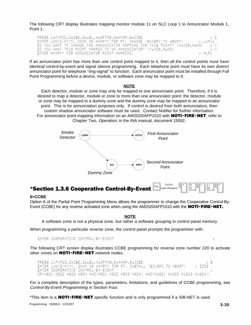
The following CRT display illustrates mapping monitor module 11 on SLC Loop 1 to Annunciator Module 1,Point 1.
PRESS@1=TYPID,2=CBE,3=LBL,4=OPTNS,5=AMAP,6=CCBE@@@@@@@@@@@@@@@@@@@@@@@@@@@@@@:@5ENTER@LXX(D/M)YY,@ZXXX@OR@AXXPYY@FOR@PT.@CHANGE@(BCKSPC@TO@ABORT)@@@@@@@:@L1M11DO@YOU@WANT@TO@CHANGE@THE@ANNUNCIATOR@MAPPING@FOR@THIS@POINT?@(Y=YES,N=NO)@@@:@YDO@YOU@WANT@THIS@POINT@MAPPED@TO@AN@ANNUNCIATOR?@(Y=YES,N=NO)@@@@@@@@@@@@@@@@:@YENTER@AXXPYY@FOR@ANNUNCIATOR@POINT@MAPPING@@@@@@@@@@@@@@@@@@@@@@@@@@@@@@:@A1P1
If an annunciator point has more than one control point mapped to it, then all the control points must haveidentical control-by-event and signal silence programming. Each telephone point must have its own distinctannunciator point for telephone "ring-signal" to function. Each annunciator point must be installed through FullPoint Programming before a device, module, or software zone may be mapped to it.
NOTEEach detector, module or zone may only be mapped to one annunciator point. Therefore, if it is
desired to map a detector, module or zone to more than one annunciator point; the detector, moduleor zone may be mapped to a dummy zone and the dummy zone may be mapped to an annunciator
point. This is for annunciation purposes only. If control is desired from both annunciators, thencustom shadow annunciator software must be used. Contact Notifier for further information.
For annunciator point mapping information on an AM2020/AFP1010 with NOTI�FIRE�NET, refer toChapter Two, Operation, in the INA manual, document 15092.
*Section 1.3.6 Cooperative Control-By-Event D}X3X6X6=CCBEOption 6 of the Partial Point Programming Menu allows the programmer to change the Cooperative Control-By-Event (CCBE) for any reverse activated zone when using the AM2020/AFP1010 with the NOTI�FIRE�NET.
NOTEA software zone is not a physical zone, but rather a software grouping in control panel memory.
When programming a particular reverse zone, the control panel prompts the programmer with:
ENTER@COOPERATIVE@CONTROL-BY-EVENT@@@@@@@@@@@@@@@@@@@@@@@@@@@@@@@@@@@@@@@@@@@@:
The following CRT screen display illustrates CCBE programming for reverse zone number 220 to activateother zones on NOTI�FIRE�NET network nodes.
PRESS@1=TYPID,2=CBE,3=LBL,4=OPTNS,5=AMAP,6=CCBE@@@@@@@@@@@@@@@@@@@@@@@@@@@@:@6ENTER@LXX(D/M)YY,@ZXXX@OR@AXXPYY@FOR@PT.@INSTALL@(BCKSPC@TO@ABORT)@@@@:@Z220ENTER@COOPERATIVE@CONTROL-BY-EVENT@@@@@@@@@@@@@@@@@@@@@@@@@@@@@@@@@@@@@@@@@@@:OR(N8Z1@N8Z2@N8Z3@N8Z4@AND(N9Z1@N9Z2@N9Z3@N9Z4)@AND(N10Z1@N10Z2@N10Z3@N10Z4))
For a complete description of the types, parameters, limitations, and guidelines of CCBE programming, seeControl-By-Event Programming in Section Four.
*This item is a NOTI�FIRE�NET specific function and is only programmed if a SIB-NET is used.
L3D64 A1P12
A9P2Z23Second Annunciator
Point
First AnnunciatorPoint
Dummy Zone
SmokeDetector

3-36 Programming 15088:H 12/23/97
4 = FPRG
Enter SoftwareType ID
Enter SoftwareType ID
Enter SoftwareType ID
Enter SoftwareType ID
Enter SoftwareType ID
Enter Software Zone, AddressableDevice, or Annunciator Point
(Backspace to Exit Mode)
Enter CustomLabel
Enter CBE List
Enter CustomLabel
Enter CBE
Equation/List *
Enter CustomLabel
Enable/DisableSignal Silence
Enter CBEEquation
Enable/DisableTracking Option
Enable/DisableDetector
Verification
Enter CBE List
Enter CustomLabel
Enable/Disable Day/Night Sensitivity
Control
Enable/DisableWalk Test
Enable/DisableTracking
Enter DetectorSensitivity
(low, med, or high)
Map toAnnunciator
Point?
EnterAnnunciator
Point
Yes
AddressableDetector
Control Module Software Zone Annunciator Point Monitor Module
Map toAnnunciator
Point?
Enter AnnunciatorPoint
Yes
Map toAnnunciator
Point?
EnterAnnunciator
Point
Yes
Map toAnnunciator
Point?
EnterAnnunciator
Point
Yes
NoNo
No
No
* Equation for Reverse Zone, List for Forward Zone** NOTI�FIRE�NET only
Enter CCBE **(Reverse Zones
Only)
Section 1.4 Full Point Programming D }X4X4=FPRGOption 4 from the Programming Menu allows the programmer to completely program of all the addressabledetectors, modules, software-defined zones and annunciator points in the AM2020/AFP1010 system. Theprogramming examples illustrate the CRT screen prompts displayed during Full Point Programming.
For a description of each of the parameters programmed here, refer to Partial Point Programming.
NOTEThe control panel continuously loops back through the Full Point Programming routine, allowing the
programmer to enter devices, software zones or annunciator points one after the other. Use theBackspace key to exit Full Point Programming.
Figure 1-13 Full Point Programming Flow Chart
(panel determines item entered and branches accordingly)

Programming 15088:H 12/23/97 3-37
Example: Programming Addressable DetectorsPhotoelectric Smoke Detector on SLC LOOP 2 programmed to activate two software zones (Z13, Z29) and acontrol module (L2M19), and also mapped to annunciator module address "02" point "02".
PRESS@1=PSYS,2=FSYS,3=PPRG,4=FPRG,5=REMV,6=PSWD,7=MSG,8=HIS@@@@@@@@@@@@@@@@@@:@4ENTER@LXX(D/M)YY,@ZXXX@OR@AXXPYY@FOR@PT.@INSTALL@(BCKSPC@TO@ABORT)@@@@@@:@L2D23ENTER@TYPE@ID@@@@@@@@@@@@@@@@@@@@@@@@@@@@@@@@@@@@@@@@@@@@@@@@@@@@@@@@@@@@@:@PHOTENTER@CONTROL-BY-EVENT@@@@@@@@@@@@@@@@@@@@@@@@@@@@@@@@@@@@@@@@@@@@@@@@@@@@@@@@@:(Z13@Z29@L2M19)@ENTER@20@CHARACTER@CUSTOM@LABEL@@@@@@@@@@@@@@@@@@@@@@@@@@@:@MAIN@LOBBY@DETECTOR@IS@THE@DETECTOR@VERIFICATION@OPTN@TO@BE@ENABLED@FOR@THIS@DEVICE?@(Y=YES,N=NO):@YENTER@THE@DETECTOR@SENSITIVITY@SELECTION@FOR@THIS@DEVICE@(L=LOW,M=MED,H=HIGH):@HIS@THE@TRACKING@OPTION@TO@BE@ENABLED@FOR@THIS@DEVICE?@(Y=YES,N=NO)@@@@@@@@@@@:@YIS@THERE@DAY/NIGHT@SENSITIVITY@CONTROL@FOR@THIS@DEVICE?@(Y=YES,N=NO)@@@@@@@@@:@YDO@YOU@WANT@THIS@POINT@MAPPED@TO@AN@ANNUNCIATOR?@(Y=YES,N=NO)@@@@@@@@@@@@@@@@:@YENTER@AXXPYY@FOR@ANNUNCIATOR@POINT@MAPPING@@@@@@@@@@@@@@@@@@@@@@@@@@@@@@:@A2P2
Example: Programming Annunciator PointsInstallation of individual annunciator points.
ENTER@LXX(D/M)YY,@ZXXX@OR@AXXPYY@FOR@PT.@INSTALL@(BCKSPC@TO@ABORT)@@@@@:@A12P10ENTER@TYPE@ID@@@@@@@@@@@@@@@@@@@@@@@@@@@@@@@@@@@@@@@@@@@@@@@@@@@@@@@@@@@@:@ADET
Example: Programming Monitor ModulesMonitor Module on SLC Loop 3 programmed to monitor a full zone of conventional 4-wire smoke detectors,and activate a software zone (Z13), and also mapped to annunciator module address "02" point "03".
ENTER@LXX(D/M)YY,@ZXXX@OR@AXXPYY@[email protected]@(BCKSPC@TO@ABORT)@@@@@@@:@L3M15ENTER@TYPE@ID@@@@@@@@@@@@@@@@@@@@@@@@@@@@@@@@@@@@@@@@@@@@@@@@@@@@@@@@@@@@@:@SCONENTER@CONTROL-BY-EVENT@@@@@@@@@@@@@@@@@@@@@@@@@@@@@@@@@@@@@@@@@@@@@@@@@@@@@@@@@:(Z13)@ENTER@20@CHARACTER@CUSTOM@LABEL@@@@@@@@@@@@@@@@@@@@@@@@@@@:@BASEMENT@DETECTORS@@IS@THE@TRACKING@OPTION@TO@BE@ENABLED@FOR@THIS@DEVICE?@(Y=YES,N=NO)@@@@@@@@@@@:@NDO@YOU@WANT@THIS@POINT@MAPPED@TO@AN@ANNUNCIATOR?@(Y=YES,N=NO)@@@@@@@@@@@@@@@@:@YENTER@AXXPYY@FOR@ANNUNCIATOR@POINT@MAPPING@@@@@@@@@@@@@@@@@@@@@@@@@@@@@@:@A2P3
Example: Programming Control ModulesControl Module on SLC Loop 2 programmed to turn on in response to an alarm condition on either of twosoftware zones (Z13 or Z29), and also mapped to annunciator module address "02" point "04".
ENTER@LXX(D/M)YY,@ZXXX@OR@AXXPYY@FOR@PT.@INSTALL@(BCKSPC@TO@ABORT)@@@@@@:@L2M19ENTER@TYPE@ID@@@@@@@@@@@@@@@@@@@@@@@@@@@@@@@@@@@@@@@@@@@@@@@@@@@@@@@@@@@@@:@CONENTER@CONTROL-BY-EVENT@@@@@@@@@@@@@@@@@@@@@@@@@@@@@@@@@@@@@@@@@@@@@@@@@@@@@@@@@:OR(Z13@Z29)@ENTER@20@CHARACTER@CUSTOM@LABEL@@@@@@@@@@@@@@@@@@@@@@@@@@@:@MAIN@LOBBY@BELLSIS@THE@SIGNAL@SILENCE@OPTION@TO@BE@ENABLED@FOR@THIS@DEVICE?@(Y=YES,N=NO)@@@@@:@YIS@THE@WALK@TEST@OPTION@TO@BE@ENABLED@FOR@THIS@DEVICE?@(Y=YES,N=NO)@@@@@@@@@@:@YDO@YOU@WANT@THIS@POINT@MAPPED@TO@AN@ANNUNCIATOR?@(Y=YES,N=NO)@@@@@@@@@@@@@@@@:@YENTER@AXXPYY@FOR@ANNUNCIATOR@POINT@MAPPING@@@@@@@@@@@@@@@@@@@@@@@@@@@@@@:@A2P4
NOTEControl modules that activate monitor modules via physical connections must not have the walk
test option enabled.

3-38 Programming 15088:H 12/23/97
Example: Programming Software ZonesSoftware Zone 13 programmed as a forward zone to activate two other software zones (Z15 and Z29), andalso mapped to annunciator module address "02" point "05".
ENTER@LXX(D/M)YY,@ZXXX@OR@AXXPYY@FOR@PT.@INSTALL@(BCKSPC@TO@ABORT)@@@@@@:@Z13ENTER@TYPE@ID@@@@@@@@@@@@@@@@@@@@@@@@@@@@@@@@@@@@@@@@@@@@@@@@@@@@@@@@@@@@@:@FZONENTER@CONTROL-BY-EVENT@@@@@@@@@@@@@@@@@@@@@@@@@@@@@@@@@@@@@@@@@@@@@@@@@@@@@@@@@:(Z15@Z29)@ENTER@20@CHARACTER@CUSTOM@LABEL@@@@@@@@@@@@@@@@@@@@@@@@@@@:@FIRST@FLOOR@@@@@@@@@DO@YOU@WANT@THIS@POINT@MAPPED@TO@AN@ANNUNCIATOR?@(Y=YES,N=NO)@@@@@@@@@@@@@@@@:@YENTER@AXXPYY@FOR@ANNUNCIATOR@POINT@MAPPING@@@@@@@@@@@@@@@@@@@@@@@@@@@@@@:@A2P5
Reverse zones on an AM2020/AFP1010 system with NOTI�FIRE�NET can be programmed with both CBEand CCBE equations. Below is an example of Zone 220 programmed as a reverse zone to activate zones onother network nodes.
ENTER@LXX(D/M)YY,@ZXXX@OR@AXXPYY@FOR@PT.@INSTALL@(BCKSPC@TO@ABORT)@@@@@@:@Z220ENTER@TYPE@ID@@@@@@@@@@@@@@@@@@@@@@@@@@@@@@@@@@@@@@@@@@@@@@@@@@@@@@@@@@@@@:@RZONENTER@CONTROL-BY-EVENT@@@@@@@@@@@@@@@@@@@@@@@@@@@@@@@@@@@@@@@@@@@@@@@@@@@@@@@@@:(@)@ENTER@COOPERATIVE@CONTROL-BY-EVENT@@@@@@@@@@@@@@@@@@@@@@@@@@@@@@@@@@@@@@@@@@@@@:OR(N8Z1@N8Z2@N8Z3@N8Z4@AND(N9Z1@N9Z2@N9Z3@N9Z4)@AND(N10Z1@N10Z2@N10Z3@N10Z4))ENTER@20@CHARACTER@CUSTOM@LABEL@@@@@@@@@@@@@@@@@@@@@@@@@@@:@LIBRARY@@@@@@@@@@@@@DO@YOU@WANT@THIS@POINT@MAPPED@TO@AN@ANNUNCIATOR?@(Y=YES,N=NO)@@@@@@@@@@@@@@@@:@N
**
* This item is a NOTI�FIRE�NET specific function and is only programmed when a SIB-NET is used.

Programming 15088:H 12/23/97 3-39
Section 1.5 Remove D }X5X5=REMVOption 5 from the Programming Menu allows the programmer to remove (from control panel memory) SLCLoop devices, software-defined zones or annunciator points. The devices can still be installed in the system,but the AM2020/AFP1010 will stop looking for these devices by not addressing them.
NOTES• Devices that are removed will not function in any capacity until reinstalled under Full Point
Programming. CAUTION - devices that have had their LEDs latched ON must be returned to theirnormal state before removal (execute System Reset for detectors or control OFF for modules).
• Unacknowledged points must be acknowledged prior to removal.
The programming example below illustrates the CRT screen prompts during removal of an SLC Loop device(smoke detector 34 on SLC Loop 10).
PRESS@1=PSYS,2=FSYS,3=PPRG,4=FPRG,5=REMV,6=PSWD,7=MSG,8=HIS@@@@@@@@@@@@@@@@@@:@5ENTER@LXX(D/M)YY,@ZXXX@OR@AXXPYY@FOR@PT.@REMOVAL@(BCKSPC@TO@ABORT)@@@@@@:@L10D34
Section 1.6 Password D }X6X6=PSWDOption 6 from the Programming Menu allows the programmer to change the Level One and Level Twopasswords for the AM2020/AFP1010.
NOTES• The AM2020/AFP1010s are shipped with initial Level One and Level Two passwords of 00000. As
a security measure, the control panel does not echo password digits to the DIA and CRT screen.Rather, it displays an asterisk (*) for each digit entered. After entering five password digits,
pressing ENTER (on the DIA) or RETURN (on the CRT) places the new password into operation.• Acceptable characters for a password are the digits 0-9.
PRESS@1=PSYS,2=FSYS,3=PPRG,4=FPRG,5=REMV,6=PSWD,7=MSG,8=HIS@@@@@@@@@@@@@@@@@@:@6PRESS@1=LEVEL@ONE,2=LEVEL@TWO@@@@@@@@@@@@@@@@@@@@@@@@@@@@@@@@@@@@@@@@@@@@@@@@:@2@@@@@ENTER@LEVEL@TWO@PASSWORD:@*****
A Forgotten Password?If a Level One or Level Two password is incorrectly entered, the panel will respond by displaying a specialcode word and prompt the programmer to reenter the password. If the password has been forgotten, recordthis code word and contact NOTIFIER. After proper authentication, the original password can be determinedfrom deciphering the code word. An example of this code word follows:
@@@ENTER@LEVEL@ONE@PASSWORD:@*****@@INVALID@PASSWORD:@@@@@@@7129406@@@@@@@@@REENTER@PASSWORD:
Section 1.7 Message D }X7X7=MSGOption 7 from the Programming Menu allows the programmer to change the 40-Character Custom User Labelfor the system. Acceptable characters for the label include Letters A though Z, digits 0 through 9, periods (.),dashes (-), and spaces.
PRESS@1=PSYS,2=FSYS,3=PPRG,4=FPRG,5=REMV,6=PSWD,7=MSG,8=HIS@@@@@@@@@@@@@@@@@@:@7ENTER@40@CHARACTER@CUSTOM@USER@LABEL@@:@NOTIFIER@@@@@@@@@@@@@@@@@@@@@@@@@@@

3-40 Programming 15088:H 12/23/97
Section 1.8 History Mode D }X8X8=HISOption 8 from the Programming Menu allows the programmer to change the parameters associated with HistoryMode. Once the History option is enabled, the AM2020/AFP1010 has the capability to store the most recent 400system events.
Figure 1-14 History Buffer Option Flow Chart
8 = HIS
Select HistorySubmenu Option 1-3
1 = START(Starts the recording of events
into the history buffer)
2 = STOP(Stops the recording of events
into the history buffer)
3 = CLEAR(Clears out selected number
of oldest events fromhistory buffer)
Enter # of Events to beCleared
(Exit Prog Mode)
After selecting option 8 from the Main Programming menu, the display will show the History ModeProgramming submenu:
PRESS@1=START,2=STOP,3=CLEAR@@@@@@@@@@@@@@@@@@@@@@@@@@@@@@@@@@@@@@@@@@@@@@@@@:

Programming 15088:H 12/23/97 3-41
The History Mode Programming submenu has three options as described below:
1=START D }X8X1XThis option allows the programmer to start storing events into the panel's history mode buffer. The followingexample enables history mode:
PRESS@1=START,2=STOP,3=CLEAR@@@@@@@@@@@@@@@@@@@@@@@@@@@@@@@@@@@@@@@@@@@@:@1
2=STOP D }X8X2XThis option allows the programmer to stop storing events into the panel's history mode buffer. The followingexample disables history mode:
PRESS@1=START,2=STOP,3=CLEAR@@@@@@@@@@@@@@@@@@@@@@@@@@@@@@@@@@@@@@@@@@@@:@2
3=CLEAR D }X8X3XThis option allows the programmer to clear out of history buffer memory a selected number (1-N, where Nrepresents the number of stored events) of the oldest history events recorded. The following exampleillustrates this by clearing out the entire history mode buffer.
PRESS@1=START,2=STOP,3=CLEAR@@@@@@@@@@@@@@@@@@@@@@@@@@@@@@@@@@@@@@@@@@@@:@3ENTER@NUMBER@ENTRIES@TO@CLEAR@(1@-@400)@@@@@@@@@@@@@@@@@@@@@@@@@@@@@@@:@400

3-42 Programming 15088:H 12/23/97

Programming 15088:H 12/23/97 3-43
Section TwoThe Alter Status Menu
The Alter Status Mode is accessed by entering the following (level 1 password required):
C | XAfter entering the Alter Status Mode, the display will show the Alter Status menu:
PRESS@1=DIS,2=CTL,3=DSEN,4=TIME,5=DIAG,6=WALK,7=GZON@@@@@@@@@@@@@@@@@@@@@@@@@@@@@@@@:
The Alter Status menu has six options, where:
1=DIS Disable - Disabling or enabling any individual addressable detector, module, or soft-ware zone in the system.
2=CTL Control - Manually turning on and off a control module.
3=DSEN Detector Sensitivity - Altering the sensitivity of any of the addressable detectors inthe system.
4=TIME Time - Resetting the system time/date clock.
5=DIAG Diagnostics - Performing system diagnostics.
6=WALK Walk Test - Allows the programmer to select which Loop Interface Boards will partici-pate in walk test and generates the walk test reports.
7=GZON Group Zone - Allows the programmer to select which zone (and its associated points)to be disabled or enabled as a group.
The Alter Status Menu flow chart is located in Figure 2-1. Detailed information on the Alter Status optionsfollows.
NOTEWhen an AM2020/AFP1010 with NOTI�FIRE�NET is in walk test mode, a trouble condition will
appear for that AM2020/AFP1010 node at the INA and/or NRT.

3-44 Programming 15088:H 12/23/97
Select Alter StatusMenu Option 1-7
1 = DIS(enable/disable of devices or
software zone)
2 = CTL(manually turn on/off a
control module)
3 = DSEN(alter sensitivity of anyaddressable detector)
4 = TIME(set the panel time/date
clock)
5 = DIAG(perform system
diagnostics)
PressALTER STATUS
key
Enter Level 1Password
ValidPassword?
Yes
No Error Message
6 = WALK(specify LIBs for Walk Test,
and Walk Test reports)
7 = GZON(Group Zone disable or
enable)
see Section 2.1
see Section 2.2
see Section 2.3
see Section 2.4
see Section 2.5
see Section 2.6
see Section 2.7
Figure 2-1 Alter Status Menu Flow Chart
Section 2.1 Disable Point C |X1X1=DISOption 1 from the Alter Status Menu allows the programmer to disable and subsequently re-enable individualdevices or zones. When a point is disabled, it is no longer polled by the AM2020/AFP1010.
The following example illustrates disabling monitor module 4 on SLC Loop 1.
NOTEThe programmer should NEVER disable a point that is in alarm.
The programmer should never turn on (using option 2 of the Alter Status Menu) or program a disabled point.Telephone (TELE) and remote page (PAGE) Type IDs can not be disabled.
PRESS@1=DIS,2=CTL,3=DSEN,4=TIME,5=DIAG,6=WALK,7=GZON@@@@@@@@@@@@@@@@@@:@1ENTER@LXX(D/M)YY,@ZXXX@OR@AXXPYY@FOR@PT.@CHANGE@(BCKSPC@TO@ABORT):@L1M4DO@YOU@WANT@THIS@POINT@DISABLED?@(Y=YES,N=NO)@@@@@@@@@@@@@@@@@@@@@@@@@ :@Y

Programming 15088:H 12/23/97 3-45
Section 2.2 Control Module C |X2X2=CTLOption 2 from the Alter Status Menu allows the programmer to selectively turn on or off control modules fromthe control panel.
The following example illustrates turning on control module 22 on SLC Loop 1.
PRESS@1=DIS,2=CTL,3=DSEN,4=TIME,5=DIAG,6=WALK,7=GZON@@@@@@@@@@@@@@@@@@@@@@@@@:@2ENTER@LXXMYY@FOR@CONTROL@MODULE@CHANGE@(BCKSPC@TO@ABORT)@@@@@@@@@@@@@@@@:@L1M22DO@YOU@WANT@POINT@TO@BE@ON@OR@OFF?@(Y=ON,N=OFF)@@@@@@@@@@@@@@@@@@@@@@@@@@@@@@:@Y
Section 2.3 Detector Sensitivity C |X3X3=DSENOption 3 from the Alter Status Menu allows the programmer to alter the sensitivity of any addressable detector.The sensitivity of a detector can be set at one of three levels - low, medium and high.
The following example illustrates setting a high sensitivity for Detector 14 on SLC Loop 3.
PRESS@1=DIS,2=CTL,3=DSEN,4=TIME,5=DIAG,6=WALK,7=GZON@@@@@@@@@@@@@@@@@@@@@@@@@:@3ENTER@LXXDYY@FOR@DETECTOR@TO@CHANGE@(BCKSPC@TO@ABORT)@@@@@@@@@@@@@@@@@@@:@L3D14ENTER@THE@DETECTOR@SENSITIVITY@SELECTION@FOR@THIS@DEVICE@(L=LOW,M=MED,H=HIGH):@H
Section 2.4 Time C |X4X4=TIMEOption 4 from the Alter Status Menu allows the programmer to reset the time/date system clock.
PRESS@1=DIS,2=CTL,3=DSEN,4=TIME,5=DIAG,6=WALK,7=GZON@@@@@@@@@@@@@@@@@@@@@@@@@:@4ENTER@THE@MONTH@(1@-@12)@@@@@@@@@@@@@@@@@@@@@@@@@@@@@@@@@@@@@@@@@@@@@@@@@@@@@:@3ENTER@THE@DAY-OF-MONTH@(1@-@31)@@@@@@@@@@@@@@@@@@@@@@@@@@@@@@@@@@@@@@@@@@@@@@:@1ENTER@THE@YEAR@(0@-@99)@@@@@@@@@@@@@@@@@@@@@@@@@@@@@@@@@@@@@@@@@@@@@@@@@@@@@:@93ENTER@THE@DAY-OF-WEEK@(1=SUN,...,7=SAT)@@@@@@@@@@@@@@@@@@@@@@@@@@@@@@@@@@@@@@:@2ENTER@THE@HOURS@IN@MILITARY@TIME@(0@-@23)@@@@@@@@@@@@@@@@@@@@@@@@@@@@@@@@@@@:@15ENTER@THE@MINUTES@(0@-@59)@@@@@@@@@@@@@@@@@@@@@@@@@@@@@@@@@@@@@@@@@@@@@@@@@@:@37NOTIFIER@@@@@@@@@@@@@@@@@@@@@@@@@@@@@@@@@ALL@SYSTEMS@NORMAL@@03:37P@03/01/97
NOTES• Military time and conventional time are the same for the hours of 1:00 am to noon. To convertconventional time to military time for the hours of 1:00 pm to midnight remove the colon from theconventional time and add the resulting number to 1200. Example: 1:34 pm conventional time is
134 + 1200 = 1334 hours military time (13 hours and 34 minutes).
• On the NOTI�FIRE�NET system, the time and date are synchronized every hour by the masterclock node on the network. The last AM2020/AFP1010, INA, or NRT on the network where the time
and date were manually programmed is the master clock node.

3-46 Programming 15088:H 12/23/97
Section 2.5 Diagnostics C |X5X5=DIAGOption 5 from the Alter Status Menu allows the programmer to perform system diagnostics.
The Diagnostics Option submenu is shown below:
PRESS@1=RVER@@@@@@@@@@@@@@@@@@@@@@@@@@@@@@@@@@@@@@@@@@@@@@@@@@@@@@@@@@@@@@@@@:@@
1=RVER - Reset Detector Verification Counters C |X5X1XThis option allows the programmer to reset the detector verification counters for all installed intelligent detectorsand clear all detector verification error conditions.The detector verification counter associated with each detector indicates how many times that detector has en-tered the alarm verification routine without producing a valid fire alarm.
The following example illustrates the execution of this option:
PRESS@1=RVER@@@@@@@@@@@@@@@@@@@@@@@@@@@@@@@@@@@@@@@@@@@@@@@@@@@@@@@@@@@@@@@@@:@1DO@YOU@WANT@TO@RESET@THE@DETECTOR@VERIFICATION@COUNTERS?@(Y=YES,N=NO)@@@@@@@@:@Y
Section 2.6 Walk Test C |X6X6=WALKOption 6 from the Alter Status Menu allows the programmer to select which LIBs will participate in walk test.Upon completion of walk test, the programmer will be able to choose from the optional walk test reports.
After Selecting option 6 from the Alter Status menu, the display will show the Walk Test submenu:
PRESS@1=SEL,2=UNP,3=UNI,4=TEST,5=UNTST,6=EXIT@@@@@@@@@@@@@@@@@@@@@@@@@@@@@@@@:
The Walk Test submenu has six options, where:
1=SEL Select - Select which LIB boards will participate in Walk Test.
2=UNP Unprogrammed Device Report - Allows the programmer to generate a report for un-programmed devices in the area designated for Walk Test.
3=UNI Uninstalled Device Report - Allows the programmer to generate a report foruninstalled devices in the area designated for Walk Test.
4=TEST Tested Devices Report - Allows the programmer to generate a report for tested de-vices in the area designated for Walk Test.
5=UNTST Untested Device Report - Allows the programmer to generate a report for untesteddevices in the area designated for Walk Test.
6=EXIT Exit Walk Test - Allows the programmer to exit/abort the Walk Test Mode.

Programming 15088:H 12/23/97 3-47
Figure 2-2 Walk Test Option Flow Chart
6 = WALK
Select Walk TestSubmenu Option 1-6
1 = SEL(select LIBs for Walk Test)
2 = UNP(generates report for
unprogrammed devices)
3 = UNI(generates report foruninstalled devices)
4 = TEST(generates report for tested
devices)
6 = EXIT(Exits Walk Test Option)
Enter LIB # for TestReport
Request/AbortTest Report
Enter LIB # Includedin Test
EnterAnother LIB
for Test?
(Exit Alter Status Mode)
5 = UNTST(generates report for untested
devices)
Yes
No
(Exit Alter Status Mode, seenotes under 1=SEL)
(Prints report, Exit Alter Status Mode)
1=SEL - Select C | X6X1XThis option allows the programmer to select which LIBs will participate in Walk Test. The following exampleselects LIBs 1 and 3 for Walk Test:
PRESS@1=SEL,2=UNP,3=UNI,4=TEST,5=UNTST,6=EXIT@@@@@@@@@@@@@@@@@@@@@@@@@@@@@@@:@1ENTER@LIB@NUMBER@TO@BE@INCLUDED@IN@WALK@TEST@(1@-@10)@@@@@@@@@@@@@@@@@@@@@@:@1DO@YOU@WANT@TO@ENABLE@MORE@LIBS@FOR@WALK@TEST?@(Y=YES,N=NO)@@@@@@@@@@@@@@@@@:@YENTER@LIB@NUMBER@TO@BE@INCLUDED@IN@WALK@TEST@(1@-@10)@@@@@@@@@@@@@@@@@@@@@@:@3DO@YOU@WANT@TO@ENABLE@MORE@LIBS@FOR@WALK@TEST?@(Y=YES,N=NO)@@@@@@@@@@@@@@@@@:@N
NOTES• Upon completion of the walk test LIB selection, a system trouble is generated to indicate the control
panel is operating under limited fire protection. Only the LIBs selected for walk test are affected.• Each LIB collects information immediately after it is selected. The programmer should not generate
a walk test report until 20 seconds after LIB selection or the report will be missing data and shouldbe considered invalid. If this happens, abort the walk test and start again.
• If one or more LIBs have been selected for walk test, additional LIBs cannot be selected without exitingwalk test.
• For every device activated during walk test, a walk test count message is sent to the printer.• Conventional devices attached to device SCON (or equivalent) can not be individually tested with
walk test, because walk test does not perform a reset on PWRC (or equivalent) devices. Do notperform a System Reset during a Walk Test. System Reset does not function properly while in WalkTest mode of operation and may result in unwanted activation of various output modules. If a systemreset occurs during a Walk Test, exit Walk Test mode and re-enter.
• Walk Test will automatically abort if no devices are tested for 15 minutes.

3-48 Programming 15088:H 12/23/97
2=UNP - Unprogrammed Device Report3=UNI - Uninstalled Device Report4=TEST - Tested Device Report5=UNTST - Untested Device Report
These options allow the programmer to generate the desired Walk Test report. These reports are generatedon a LIB basis. They use the same display format as the Point Read option under Read Status except for thestatus field which is report-specific (no Control-by-Event or annunciator point mapping is reported). Theresults of the report are not displayed on the CRT screen but are printed out on the printer.
1=REQUEST Begins the selected report.2=ABORT Aborts the selected report in progress.
NOTE Only one report can be conducted at any one time.
WARNING: Do not reset the Control Panel while in Walk Test mode. Execution of a System Reset during aWalk Test may cause unwanted activation of various output modules (CMX, XPC, etc.). If a Sys-tem Reset occurs during a Walk Test, exit Walk Test Mode and re-enter.
The following CRT screen illustrates conducting a Tested Device Report. The printout of this test is illustratedin Figure 2-3.
PRESS@1=SEL,2=UNP,3=UNI,4=TEST,5=UNTST,6=EXIT@@@@@@@@@@@@@@@@@@@@@@@@@@@@@@@@:@4ENTER@LIB@NUMBER@FOR@WALK@TEST@REPORT@(1@-@10)@@@@@@@@@@@@@@@@@@@@@@@@@@@@@@:@1PRESS@1=REQUEST,2=ABORT@@@@@@@@@@@@@@@@@@@@@@@@@@@@@@@@@@@@@@@@@@@@@@@@@@@@@@:@1LIB@01@TESTED@DEVICE@REPORT@BEGIN@@@@@@@@@@@@@@@@@@@@@@@@@@@@04:32P@03/01/97NOTIFIER@@@@@@@@@@@@@@@@@@@@@@@@@@@@@@@@@ALL@SYSTEMS@NORMAL@@04:32P@03/01/97LIB@01@TESTED@DEVICE@REPORT@END@@@@@@@@@@@@@@@@@@@@@@@@@@@@@@04:32P@03/01/97NOTIFIER@@@@@@@@@@@@@@@@@@@@@@@@@@@@@@@@@ALL@SYSTEMS@NORMAL@@04:32P@03/01/97
6=EXIT - Exit Walk Test C |X6X6XThis option allows the programmer to exit/abort Walk Test. In order to exit/abort Walk Test Mode, reenterAlter Status Mode and choose option 6 from the Walk Test submenu.
The following example demonstrates exiting/aborting Walk Test:
PRESS@1=SEL,2=UNP,3=UNI,4=TEST,5=UNTST,6=EXIT@@@@@@@@@@@@@@@@@@@@@@@@@@@@@@@@:@6
NOTEUpon exiting/aborting Walk Test, the Walk Test system trouble is cleared and the AM2020/AFP1010
resumes full fire protection.
C | X6X(2,3,4 or 5)X
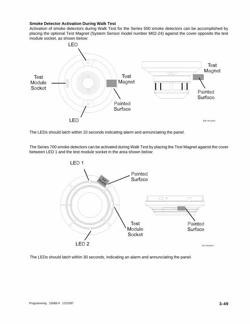
Programming 15088:H 12/23/97 3-49
The LEDs should latch within 10 seconds indicating alarm and annunciating the panel.
The Series 700 smoke detectors can be activated during Walk Test by placing the Test Magnet against the coverbetween LED 1 and the test module socket in the area shown below:
Smoke Detector Activation During Walk TestActivation of smoke detectors during Walk Test for the Series 500 smoke detectors can be accomplished byplacing the optional Test Magnet (System Sensor model number M02-24) against the cover opposite the testmodule socket, as shown below:
The LEDs should latch within 30 seconds, indicating an alarm and annunciating the panel.
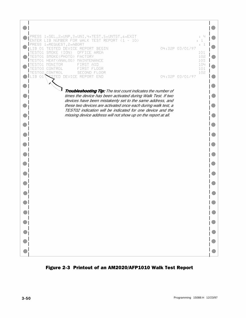
3-50 Programming 15088:H 12/23/97
PRESS@1=SEL,2=UNP,3=UNI,4=TEST,5=UNTST,6=EXIT@@@@@@@@@@@@@@@@@@@@@@@@@@:@4ENTER@LIB@NUMBER@FOR@WALK@TEST@REPORT@(1@-@10)@@@@@@@@@@@@@@@@@@@@@@@@:@1PRESS@1=REQUEST,2=ABORT@@@@@@@@@@@@@@@@@@@@@@@@@@@@@@@@@@@@@@@@@@@@@@@@:@1LIB@01@TESTED@DEVICE@REPORT@BEGIN@@@@@@@@@@@@@@@@@@@@@@04:32P@03/01/97TEST01@SMOKE@(ION)@@OFFICE@AREA@@@@@@@@@@@@@@@@@@@@@@@@@@@@@@@@@@@@@@@@101TEST01@SMOKE(PHOTO)@FACTORY@@@@@@@@@@@@@@@@@@@@@@@@@@@@@@@@@@@@@@@@@@@@102TEST01@HEAT(ANALOG)@MAINTENANCE@@@@@@@@@@@@@@@@@@@@@@@@@@@@@@@@@@@@@@@@103TEST01@MONITOR@@@@@@FIRST@AID@@@@@@@@@@@@@@@@@@@@@@@@@@@@@@@@@@@@@@@@@@104TEST03@CONTROL@@@@@@FIRST@FLOOR@@@@@@@@@@@@@@@@@@@@@@@@@@@@@@@@@@@@@@@@101TEST02@CONTROL@@@@@@SECOND@FLOOR@@@@@@@@@@@@@@@@@@@@@@@@@@@@@@@@@@@@@@@102LIB@01@TESTED@DEVICE@REPORT@END@@@@@@@@@@@@@@@@@@@@@@@@04:32P@03/01/97
Figure 2-3 Printout of an AM2020/AFP1010 Walk Test Report
Troubleshooting Tip:Troubleshooting Tip:Troubleshooting Tip:Troubleshooting Tip:Troubleshooting Tip: The test count indicates the number oftimes the device has been activated during Walk Test. If twodevices have been mistakenly set to the same address, andthese two devices are activated once each during walk test, aTEST02 indication will be indicated for one device and themissing device address will not show up on the report at all.

Programming 15088:H 12/23/97 3-51
Section 2.7 Group Zone Disable
7=GZONOption 7 from the Alter Status Menu allows the programmer to disable and subsequently re-enable allappropriately mapped points (input devices and zones) associated with a particular software zone. When apoint is disabled, it is no longer polled by the AM2020/AFP1010.
When a zone is disabled using this feature, a trouble message is generated for this zone. Then the entire CBEdatabase is searched for all input devices and zones, looking for this "group" zone to be the first zone in eachpoint's individual CBE. A trouble message will be generated for each point (input device or zone) matching theabove criteria as it is found and disabled. During the search process the user interface is locked out.
The following example illustrates group disabling Zone 2.
NOTE:The programmer should never program a disabled point.
C |X7X
PRESS@1=DIS,2=CTL,3=DSEN,4=TIME,5=DIAG,6=WALK,7=GZON@@@@@@@@@@@@@@@@@@@@@@@@:@7ENTER@ZXXX@FOR@ GROUP @ZONE @CHANGE@@@@@@@@@@@@@@@@@@@@@@@@@@@@@@@@@@@@@@@@@:@Z2DO@YOU@WANT@THIS@GROUP@ZONE@DISABLED?@(Y=YES,N=NO)@@@@@@@@@@@@@@@@@@@@@@@@@@:@Y
Example: tnioP EBC
1Z )(2Z )(3Z )(
1D1L )1Z(2D1L )2Z(3D1L )3Z(1M1L )1Z(2M1L )2Z(3M1L )3Z(
As a result of disabling Z2 using the groupzone disable function, L1D2 and L1M2 willautomatically be disabled as well.
The "first zone" does not necessarily mean being the first operand in a CBE. A zone can be located anywherewithin the CBE. The following CBE examples all have the same effect for group zone functions:
(Z1)(Z1 L1M1)(L1M1 Z1)(L1M1 L1M2 Z1 Z2)
Z1 is the first zone found in each individual CBE.

3-52 Programming 15088:H 12/23/97
All point addresses for devices, software zones, and annunciator points must be programmed with anappropriate software type identification. Software type I.D.s allow the AM2020/AFP1010 to identify the typeand configuration of specific devices, zones, and annunciator points associated with the panel.
Each type I.D. is categorized by groups. There are 18 separate groups of software type I.D.s which aredefined in the tables on the following pages. Each table consists of the following format.
Type I.D . - This is the software type entered by the programmer for a particular point.
Display Label - The characters displayed for addressable devices, zones, and annunciator points on thecontrol panel during alarm, trouble, and read status conditions.
Type of Device - Type of devices compatible with, and/or description of operating parameters for, theparticular type I.D.
The control panel will not permit the changing of a Software Type I.D. in one group to a Software Type I.D. inanother group. To accomplish this, the device must be reinstated with the Software Type I.D. of the desiredgroup by using the Full Point Programming option of the Main Programming Menu.
NOTEThe XP Transponder will revert to local program operation upon loss of communications with theAM2020/AFP1010. Therefore, use extreme care when assigning software Type I.D.s to XP Tran-
sponder circuits. For instance, an XP circuit assigned software type I.D. SPSU will initiate a super-visory condition under communication with the AM2020/AFP1010, but will result in an alarm condi-
tion under local XP operation.
Section ThreeSoftware Type I.D.s
Group 1: Addressable Detectors
.D.IepyT lebaLyalpsiD eciveDfoepyT
OBMC )OBMOC(EKOMS .rotceteDlamrehT/cirtceleotohP/noitazinoInoitanibmoCtnegilletnI157-XPI
THPF DTOHPDEXIF rotceteDekomScirtceleotohPtnegilletnI157/155-XDS dexifahtiw.)desuebtondluohsdnaetelosbosiepyterawtfossihT(.levelytivitisnes
RHTF DREHTDEXIF rosneSlamrehTtnegilletnI155-XDF sihT(.levelytivitisnesdexifahtiwLUteemtonseoddnasnoitacilppanaidanaCnidesuebylnonacepyterawtfos
.).S.Uehtniesurofstnemeriuqerytivitisnes
NOI )NOI(EKOMS .rotceteDekomSnoitazinoItnegilletnI157/155-XPC
DNOI TEDTCUDNOI rotceteDekomSnoitazinoItnegilletnI157-155-XPC ytivitisnesdexifahtiwrotcetedrehtollA.detsujdaebtonnacrotcetedsihtfoytivitisnesehT(.levelnoitcnujnocnidesusirotcetedsihT.)NOIepytottnelaviuqeeblliwsnoitcnuf
.gnisuohrotcetedtcud105-XHDehthtiw
HNOI PHNOIEKOMS rotceteDekomSnoitazinoItnegilletnI157-XPC nacepyTerawtfoSsihT(.snoitpognimmargorpemasehtsahdnasnoitacilppanaidanaCnidesuebylno
.)NOIepytsa
LNOI PLNOIEKOMS rotceteDekomSnoitazinoItnegilletnI155-XPC nacepyTerawtfoSsihT(.snoitpognimmargorpemasehtsahdnasnoitacilppanaidanaCnidesuebylno
.)NOIepytsa
TOHP )OTOHP(EKOMS .rotceteDekomScirtceleotohPtnegilletnI157/155-XDS 157/155-XDSehTehthtiwdesunehwepyterawtfostnereffidaeriuqertonseodrotcetedotohp
.gnisuohrotcetedtcud105-XHD
REHT )GOLANA(TAEH .rosneSlamrehTtnegilletnIR155-XDFro155-XDF

Programming 15088:H 12/23/97 3-53
Group 2: Output Modules• These software types cannot be programmed for Signal Silence.• These software types do not have any control-by-event programming.• The two tabs on the CMX must not be broken for these software types unless they are Form-C relay
type devices.
Display Label
ALARMS PEND
DACT CONNECT
GN ALRM FORC
GN ALARM
GENERAL PEND
GN TRBL FORC
PAGE
POWER (CONV)
GN SUPR FORC
TELEPHONE
TRBLS PEND
TROUBLE FORC
TROUBLE
GN WAT FORC
GN WATER FLW
Type I.D.
APND
DACT
GAC
GAS
GPND
GTC
PAGE
PWRC
SSC
TELE
TPND
TRC
TRS
WFC
WFS
Type of Device
CMX Control Module or an XPC-8 circuit that will activate upon receipt of analarm condition, and remain in the ON state until all alarms have been ACKNOWL-EDGED.
CMX Control Module configured as a Form-C relay or an XPR-8 relay that willdelay the reporting of AC power loss. Any other trouble condition will be reportedimmediately. This module is used in conjunction with a digital alarm communica-tor.
CMX Control Module configured as a Form-C relay or an XPR-8 relay to switchpower to a Reverse Polarity Trip Device for NFPA 72-1993 Remote Station FireAlarm Systems applications (RPT-680 required). This type can also be used forgeneral alarm activation.
CMX Control Module or an XPC-8 circuit configured as a Municipal BoxTransmitter for NFPA 72-1993 Auxiliary Fire Alarm Systems applications (MBT-1 required). This type can also be used for general alarm activation.
CMX Control Module or an XPC-8 circuit that will activate upon receipt of analarm and/or trouble condition, and remain in the ON state until all events havebeen ACKNOWLEDGED.
CMX Control Module configured as a Form-C relay or an XPR-8 relay activatedunder any System Trouble condition.
CMX Control Module or an XPC-8 circuit configured for remote paging(RPJ-1 required).
CMX Control Module configured as a Form-C relay used to momentarilyinterrupt power (during system reset) to conventional 4-wire smoke detectorspowered from a remote main power supply.
CMX Control Module configured as a Form-C relay or an XPR-8 relay activatedunder any Supervisory condition (includes sprinkler type).
CMX Control Module or an XPC-8 circuit configured for telephone operation.Note: The CMX will not provide a ring-back signal when a call is placed.
CMX Control Module or an XPC-8 circuit that will activate upon receipt of atrouble condition, and remain in the ON state until all troubles have beenACKNOWLEDGED.
CMX Control Module configured as a Form-C relay or an XPR-8 relay that willactivate upon receipt of a trouble condition(s) and remain in the ON state until thetrouble(s) clear(s).
CMX Control Module or an XPC-8 circuit that will activate upon receipt of atrouble condition(s) and remain in the ON state until the trouble(s) clear(s).
CMX Control Module configured as a Form-C relay or an XPR-8 relay activatedunder any Water Flow condition.
CMX Control Module or an XPC-8 circuit configured as a Notification ApplianceCircuit, activated under any Water Flow alarm condition.

3-54 Programming 15088:H 12/23/97
Group 3: Software Zones
• A Forward-Activating Zone is a software zone in control panel memory which once activated by aninput device or other forward zone may in turn activate other zones and/or output devices directly.Zones and output devices activated by a forward zone are contained in the CBE List of that forwardzone.
• A Reverse-Activating Zone is a software zone in control panel memory which if not activated directlyby an input device or forward zone may be activated through an associated CBE equation. A ReverseZone may be referenced in other CBE Equations.
Type of Device
A software-defined zone that is forward-activating.A software-defined zone that is reverse-activating.
Type I.D.
FZONRZON
Display Label
FORWARD ZONEREVERSE ZONE
Type of Device
MMX Monitor Module or an XPM-8 circuit used to monitor normally-open contact, shorting-type devices other than 4-wire smoke detectors(i.e. conventional heat detectors, pull stations, etc.).
BGX-101L Addressable Manual Pull Station.
MMX Monitor Module or an XPM-8 circuit used to monitor normally-closed contact, opening-type devices.
MMX Monitor Module or an XPM-8 circuit that functions identically toSoftware Type I.D. NONA with one exception - subsequent alarms fromthis type will not reactivate silenced output devices - once silenced,outputs will remain silenced until reactivated by another software type (orcleared by System Reset and reactivated).
MMX Monitor Module or an XPM-8 circuit used to monitor normally-open contact, shorting-type non-alarm devices. Activation of a modulewith Software Type I.D. NONA will not initiate a fire alarm condition:
• System Alarm LED will not illuminate.• Does not activate alarm status line count on a CRT.• No affect on modules programmed as APND (alarm pending) or GPND (general event pending).• Alarm, clear alarm, or acknowledgments are not reported for this type.
BGX-10 Addressable Manual Pull Station.
MMX Monitor Module used to monitor conventional 4-wire smoke detec-tors. This module has a longer reset period than modules programmed asMON.
MMX Monitor Module or an XPM-8 circuit dedicated to a Water FlowAlarm device.
Type I.D.
MON
MPUL
NCMN
NOA
NONA
PULL
SCON
WAT
Display Label
MONITOR
MON PULL STA
MON NORM CLD
NON ALARM
NON ALM MON
PULL STATION
SMOKE (CONV)
WATER FLOW
Group 4: Alarm Initiation Modules
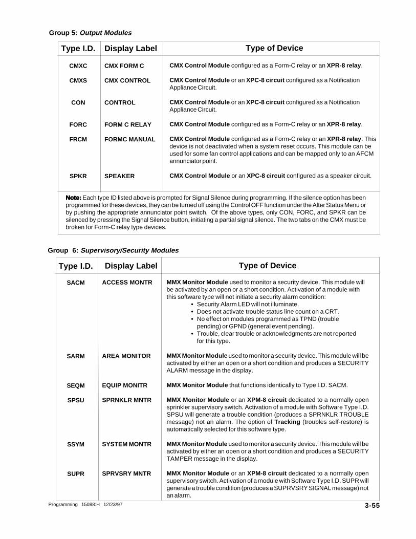
Programming 15088:H 12/23/97 3-55
Group 5: Output Modules
Display Label
CMX FORM C
CMX CONTROL
CONTROL
FORM C RELAY
FORMC MANUAL
SPEAKER
Type I.D.
CMXC
CMXS
CON
FORC
FRCM
SPKR
Group 6: Supervisory/Security Modules
Note:Note:Note:Note:Note: Each type ID listed above is prompted for Signal Silence during programming. If the silence option has beenprogrammed for these devices, they can be turned off using the Control OFF function under the Alter Status Menu orby pushing the appropriate annunciator point switch. Of the above types, only CON, FORC, and SPKR can besilenced by pressing the Signal Silence button, initiating a partial signal silence. The two tabs on the CMX must bebroken for Form-C relay type devices.
Type of Device
CMX Control Module configured as a Form-C relay or an XPR-8 relay .
CMX Control Module or an XPC-8 circuit configured as a NotificationAppliance Circuit.
CMX Control Module or an XPC-8 circuit configured as a NotificationAppliance Circuit.
CMX Control Module configured as a Form-C relay or an XPR-8 relay .
CMX Control Module configured as a Form-C relay or an XPR-8 relay . Thisdevice is not deactivated when a system reset occurs. This module can beused for some fan control applications and can be mapped only to an AFCMannunciator point.
CMX Control Module or an XPC-8 circuit configured as a speaker circuit.
Type I.D.
SACM
SARM
SEQM
SPSU
SSYM
SUPR
Display Label
ACCESS MONTR
AREA MONITOR
EQUIP MONITR
SPRNKLR MNTR
SYSTEM MONTR
SPRVSRY MNTR
Type of Device
MMX Monitor Module used to monitor a security device. This module willbe activated by an open or a short condition. Activation of a module withthis software type will not initiate a security alarm condition:
• Security Alarm LED will not illuminate.• Does not activate trouble status line count on a CRT.• No effect on modules programmed as TPND (trouble
pending) or GPND (general event pending).• Trouble, clear trouble or acknowledgments are not reported
for this type.
MMX Monitor Module used to monitor a security device. This module will beactivated by either an open or a short condition and produces a SECURITYALARM message in the display.
MMX Monitor Module that functions identically to Type I.D. SACM.
MMX Monitor Module or an XPM-8 circuit dedicated to a normally opensprinkler supervisory switch. Activation of a module with Software Type I.D.SPSU will generate a trouble condition (produces a SPRNKLR TROUBLEmessage) not an alarm. The option of Tracking (troubles self-restore) isautomatically selected for this software type.
MMX Monitor Module used to monitor a security device. This module will beactivated by either an open or a short condition and produces a SECURITYTAMPER message in the display.
MMX Monitor Module or an XPM-8 circuit dedicated to a normally opensupervisory switch. Activation of a module with Software Type I.D. SUPR willgenerate a trouble condition (produces a SUPRVSRY SIGNAL message) notan alarm.

3-56 Programming 15088:H 12/23/97
Group 12: Annunciator Input
Type I.D.Type I.D.Type I.D.Type I.D.Type I.D.
AINP
Display LabelDisplay LabelDisplay LabelDisplay LabelDisplay Label
ANN INPUT
Type of Device
Annunciator Point that indicates the state of any generic input (softwarezone, intelligent detector, monitor module or XPM-8 circuit) mapped to it.
Group 8: Annunciator Control
Display Label
ANN ACK/STEP
ANN LAMP TST
ANN RESET
ANN SIG SIL
Display Label
ANN ZONE
Display Label
ANN DETECTOR
Display Label
ANN MONITOR
Type I.D.
AAST
ALMP
ARES
ASGS
Type I.D.
AZON
Type I.D.
ADET
Type I.D.
AMON
Group 7: Evacuation Modules
Type of Device
CMX Control Module or an XPC-8 circuit configured as a NotificationAppliance Circuit, activated on General Alarm, for NFPA 72-1993 Local FireAlarm Systems applications.
Type of Device
Annunciator Point used to execute ACKNOWLEDGE/STEP.
Annunciator Point used to execute LAMP TEST.
Annunciator Point used to execute SYSTEM RESET.
Annunciator Point used to execute SIGNAL SILENCE.
Type of Device
Annunciator Point that indicates the state of any software zone mappedto it.
Type of Device
Annunciator Point that indicates the state of any intelligent detectormapped to it.
Type of Device
Annunciator Point that indicates the state of any MMX Monitor Module orXPM-8 circuit mapped to it.
Group 9: Annunciator Zone
Group 10: Annunciator Detector
Group 11: Annunciator Module
Type I.D.
EVGA
Display Label
GN ALARM EVC
Note: This software type cannot be silenced if a module of software type WAT (Water Flow) has been activated.
Note: Items in groups 9,10 and 11 may be re-mapped to group 12 only.
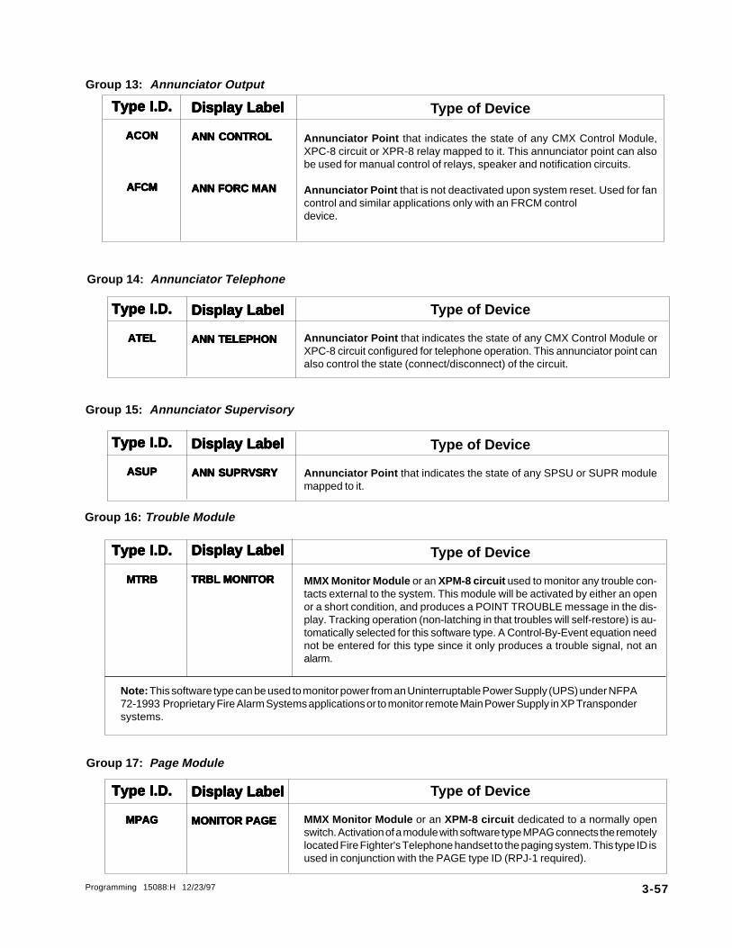
Programming 15088:H 12/23/97 3-57
Group 13: Annunciator Output
Type I.D.Type I.D.Type I.D.Type I.D.Type I.D.
ACONACONACONACONACON
AFCMAFCMAFCMAFCMAFCM
Type I.D.Type I.D.Type I.D.Type I.D.Type I.D.
ATELATELATELATELATEL
Type I.D.Type I.D.Type I.D.Type I.D.Type I.D.
ASUPASUPASUPASUPASUP
Type I.D.Type I.D.Type I.D.Type I.D.Type I.D.
MTRBMTRBMTRBMTRBMTRB
Type I.D.Type I.D.Type I.D.Type I.D.Type I.D.
MPAGMPAGMPAGMPAGMPAG
Display LabelDisplay LabelDisplay LabelDisplay LabelDisplay Label
ANN CONTROLANN CONTROLANN CONTROLANN CONTROLANN CONTROL
ANN FORC MANANN FORC MANANN FORC MANANN FORC MANANN FORC MAN
Display LabelDisplay LabelDisplay LabelDisplay LabelDisplay Label
ANN TELEPHONANN TELEPHONANN TELEPHONANN TELEPHONANN TELEPHON
Display LabelDisplay LabelDisplay LabelDisplay LabelDisplay Label
ANN SUPRVSRYANN SUPRVSRYANN SUPRVSRYANN SUPRVSRYANN SUPRVSRY
Display LabelDisplay LabelDisplay LabelDisplay LabelDisplay Label
TRBL MONITORTRBL MONITORTRBL MONITORTRBL MONITORTRBL MONITOR
Display LabelDisplay LabelDisplay LabelDisplay LabelDisplay Label
MONITOR PAGEMONITOR PAGEMONITOR PAGEMONITOR PAGEMONITOR PAGE
Group 15: Annunciator Supervisory
Group 16: Trouble Module
Group 17: Page Module
Group 14: Annunciator Telephone
Type of Device
Annunciator Point that indicates the state of any CMX Control Module,XPC-8 circuit or XPR-8 relay mapped to it. This annunciator point can alsobe used for manual control of relays, speaker and notification circuits.
Annunciator Point that is not deactivated upon system reset. Used for fancontrol and similar applications only with an FRCM controldevice.
Type of Device
Annunciator Point that indicates the state of any CMX Control Module orXPC-8 circuit configured for telephone operation. This annunciator point canalso control the state (connect/disconnect) of the circuit.
Type of Device
Annunciator Point that indicates the state of any SPSU or SUPR modulemapped to it.
Type of Device
MMX Monitor Module or an XPM-8 circuit used to monitor any trouble con-tacts external to the system. This module will be activated by either an openor a short condition, and produces a POINT TROUBLE message in the dis-play. Tracking operation (non-latching in that troubles will self-restore) is au-tomatically selected for this software type. A Control-By-Event equation neednot be entered for this type since it only produces a trouble signal, not analarm.
Type of Device
MMX Monitor Module or an XPM-8 circuit dedicated to a normally openswitch. Activation of a module with software type MPAG connects the remotelylocated Fire Fighter's Telephone handset to the paging system. This type ID isused in conjunction with the PAGE type ID (RPJ-1 required).
Note: This software type can be used to monitor power from an Uninterruptable Power Supply (UPS) under NFPA72-1993 Proprietary Fire Alarm Systems applications or to monitor remote Main Power Supply in XP Transpondersystems.

3-58 Programming 15088:H 12/23/97
Group 18: Annunciator Manual Mode
Annunciator Point that indicates manual mode for an annunciator module.The annunciator point can also turn the manual mode off or on. This type I.D.is used in conjunction with INA ACS or FACP shadow point programming.
Type I.D. Display Label Type of Device
AMAN ANN MANUAL

Programming 15088:H 12/23/97 3-59
Section FourControl-By-Event Programming
4.1 Control-By-Event Programming
IntroductionControl-By-Event (CBE) Programming is used to provide a variety of responses based on variouscombinations of events (initiating conditions). The Control-By-Event Programming controls the interactionbetween the alarm initiating devices, the internal software zones, and the alarm notification appliancesassociated with an AM2020/AFP1010.
NOTEA software zone is not a physical zone, but rather a software grouping in control panel memory.
Software ZonesThe AM2020/AFP1010 contains 240 software zones to be used in CBE programming. These software zonesare broken into two types, Forward-Activating Zones (FZON) and Reverse-Activating Zones (RZON). Theseforward and reverse zones must be grouped separately, with the forward group always preceding the reversegroup. This is accomplished by setting the Zone Boundary (see Section 1.1.5, Zone Boundary, for moreinformation on setting the zone boundary). Once the boundary is set, all software zone numbers above theZone Boundary are RZONs and all software zones below and including the Zone Boundary are FZONs.
Forward-Activating ZonesFZONs are used to activate output devices and/or other software zones. The software zones that can beactivated, however, must have a higher zone number than the FZON being utilized.
Reverse Activating ZonesRZONs are activated from input devices and/or other software zones. The software zones that can be usedto activate a reverse zone must have a lower zone number than the RZON being activated.
Lists and EquationsControl-By-Event Programming can be accomplished in two ways, via the List and the Equation. Lists areused for initiating devices (detectors and monitor modules) and forward activating zones, where as, Equationsare used for output devices (control modules) and reverse activating zones.
When an initiating device or forward-activating zone is programmed with a List, the AM2020/AFP1010activates all the items, called Operands, in the list when activation of the device or zone occurs. Theoperands listed for an initiating device can be notification modules and/or software zones (forward or reverseactivating). For a forward activating zone, the operands can be forward zones that are higher than its address,reverse activating zones and/or control modules.
Example:
A photoelectric detector has a List of (L1M1 L2M2), where L1M1 and L2M2 are control modules. When thedetector is in alarm, all the items in the Control-By-Event List are enabled so both control modules areactivated.

3-60 Programming 15088:H 12/23/97
The real power of the CBE Programming comes from the equation, which is evaluated by the control panel todetermine a variety of alarm initiating conditions. The equation provides the real decision-making abilitythrough the use of an operator acting on a set of operands. The operands for an output module can be initiatingdevices, software zones (forward or reverse-activating), or control modules assigned an address lower thanits own. For a reverse-activating zone, the operands can be initiating devices, forward zones, or reversezones that are lower than its address.
The format for an equation is shown below, where the operators are OR, AND, NOT, XZONE, DEL, SDEL, andTIM; and the operands are groupings of initiating devices and/or software zones, as well as informationspecific to the format of individual operators.
Operator(- - - - Operands - - - -)
Examples: OR(Z9 Z15 Z23)AND(L1D1 Z3 L1D35 L1D72)NOT(Z23)XZONE(Z23)DEL(HH.MM.SS HH.MM.SS (L1M1))SDEL(HH.MM.SS HH.MM.SS (Z1))TIM(SU MO TU WE TR FR SA HH.MM HH.MM)
All of the operator formats above are explained in detail on the following pages.
Control-By-Event Programming Constraints• There can only be one DEL or SDEL operator in a control-by-event equation, not both.• If there is no duration time field in a DEL or SDEL, the equation will always be activated.• The maximum value of DELAY TIME + DURATION TIME is 255:59:59.• If either the day, month or year field is omitted, that field is assumed to be all allowable values of the
field omitted. Example: 12--90 is equivalent to any day in December 1990.• The HH.MM field for START TIME and STOP TIME uses military time.• The HH.MM field for STOP TIME must be greater than the START TIME.• The maximum value of START TIME or STOP TIME is 24:00.• If an alarm condition occurs, all active TIM devices will be deactivated. All TIM equations will be
ignored until all alarms are restored, at which point all TIM devices will return to their proper state.
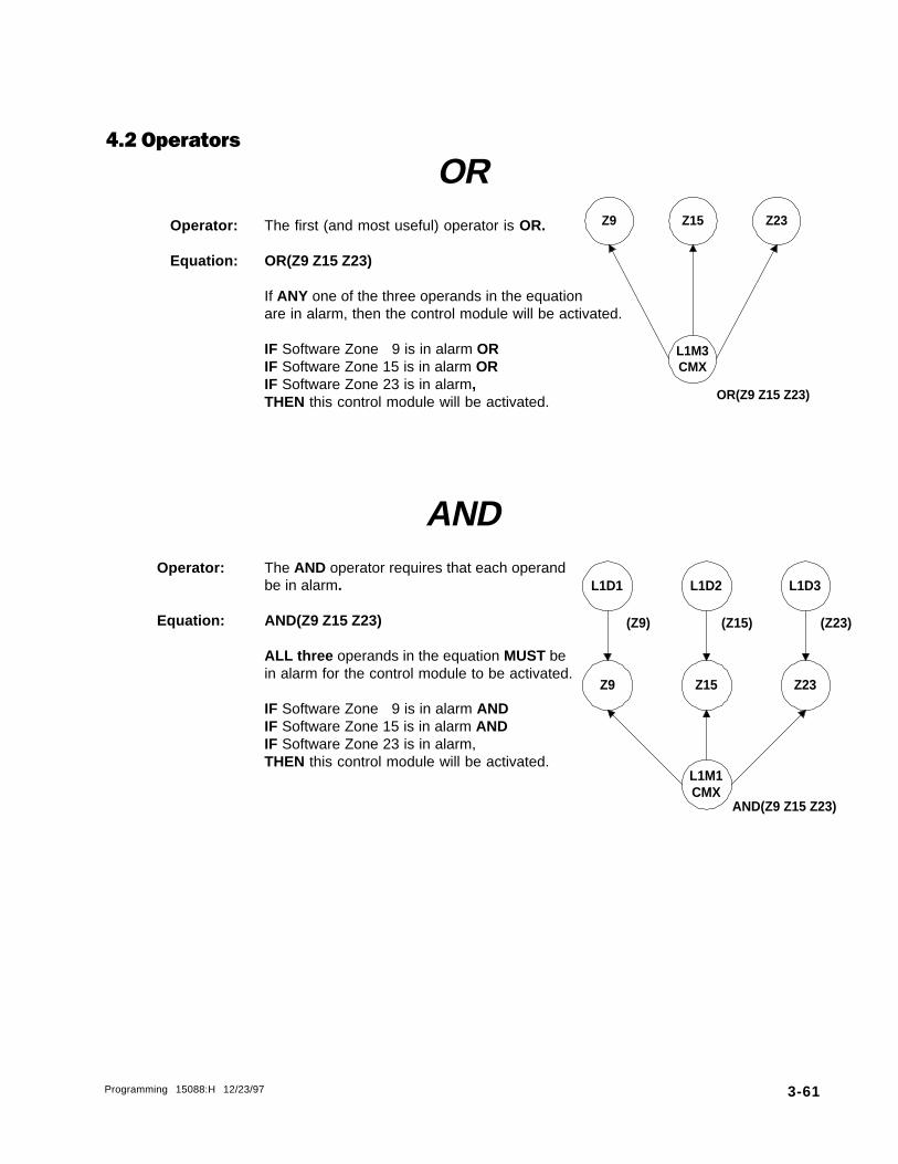
Programming 15088:H 12/23/97 3-61
Z23Z15
L1M3CMX
Z9
OR(Z9 Z15 Z23)
4.2 Operators
OROperator: The first (and most useful) operator is OR.
Equation: OR(Z9 Z15 Z23)
If ANY one of the three operands in the equationare in alarm, then the control module will be activated.
IF Software Zone 9 is in alarm ORIF Software Zone 15 is in alarm ORIF Software Zone 23 is in alarm,THEN this control module will be activated.
ANDOperator: The AND operator requires that each operand
be in alarm.
Equation: AND(Z9 Z15 Z23)
ALL three operands in the equation MUST bein alarm for the control module to be activated.
IF Software Zone 9 is in alarm ANDIF Software Zone 15 is in alarm ANDIF Software Zone 23 is in alarm,THEN this control module will be activated.
L1D1 L1D2
Z15Z9
L1D3
Z23
L1M1CMX
AND(Z9 Z15 Z23)
(Z9) (Z23)(Z15)

3-62 Programming 15088:H 12/23/97
NOTOperator: The NOT operator inverts the state of the operand
(activated to deactivated OR deactivated to activated).
Equation: NOT(Z2)
The control module will remain activated UNTILthe operand comes into alarm.
IF Software Zone 2 is in alarm,THEN this control module will be deactivated.
XZONEOperator: For Cross Zone operation, the XZONE
counting operator may be used.
Equation: XZONE(Z23)
IF ANY combination of two or more initiatingdevices (L1D1, L1D2, L1D3, L1D4)that have been programmed (Control-By-Event)to this software zone (Z23) come into alarm,THEN this control module will be activated.
Z2
L1M1CMX
L1D4
NOT(Z2)
(Z2)
L1D3L1D2
L1M3CMX
L1D1 L1D4
Z23
(Z23) (Z23) (Z23) (Z23)
XZONE(Z23)

Programming 15088:H 12/23/97 3-63
Duration(optional)
InternalEquation
Delay
DELOperator: For delayed operation, the DEL operator is used.
Equation: DEL(HH.MM.SS HH.MM.SS (Z1))
Example: L1M3 activates Forward Activating Zone 223 (Z223).L1M2 CBE is: DEL(00.00.30 00.01.30 (Z223))
IF Z223 has been active for 30 secondsTHEN L1M2 will become active. L1M2 will stay activefor 1 minute and 30 seconds provided that Zone Z223remains active.
Time line0:00 0:30 1:00 1:30 2:00 2:30+————+————+————+————+————+Z223 L1M2 L1M2active active inactive
NOTES• The entire DEL equation consumes at least 11 bytes (including a 3-byte internal equation). The internal
equation can be a complex equation many bytes in size.• If a delay of zero is entered (00.00.00), the equation will evaluate true as soon as the internal equation
evaluates true and will remain that way for the specified duration, unless the internal equationbecomes false.
• If no duration is specified, then the device will not be deactivated until a reset occurs or the internalequation evaluates false.
Z223
L1M2CMX
L1M3
(Z223)
DEL(00.00.30 00.01.30(Z223))

3-64 Programming 15088:H 12/23/97
Stop Time(optional)
Start Time(optional)
Activation Date(optional)
Activation Day(optional)
Start Time(optional)
Stop Time(optional)
TIMOperator:Operator:Operator:Operator:Operator: The TIMTIMTIMTIMTIM operator is used to specify activation on specific days of the week or year.
Equation:Equation:Equation:Equation:Equation: TIM(SU MO TU WE TR FR SA HH.MM HH.MM)TIM(SU MO TU WE TR FR SA HH.MM HH.MM)TIM(SU MO TU WE TR FR SA HH.MM HH.MM)TIM(SU MO TU WE TR FR SA HH.MM HH.MM)TIM(SU MO TU WE TR FR SA HH.MM HH.MM)(Type 1)
Example:Example:Example:Example:Example: If Z221 CBE is: TIM(SA SU 7.30 13.59)If Z221 CBE is: TIM(SA SU 7.30 13.59)If Z221 CBE is: TIM(SA SU 7.30 13.59)If Z221 CBE is: TIM(SA SU 7.30 13.59)If Z221 CBE is: TIM(SA SU 7.30 13.59)Zone Z221 will be active on Saturdays and Sundays from 7:30AM to 1:59PM.
Equation:Equation:Equation:Equation:Equation: TIM(MM-DD-YY HH.MM HH.MM)TIM(MM-DD-YY HH.MM HH.MM)TIM(MM-DD-YY HH.MM HH.MM)TIM(MM-DD-YY HH.MM HH.MM)TIM(MM-DD-YY HH.MM HH.MM)
(Type 2)
Examples:Examples:Examples:Examples:Examples: If Z222 CBE is: TIM(7-4-)If Z222 CBE is: TIM(7-4-)If Z222 CBE is: TIM(7-4-)If Z222 CBE is: TIM(7-4-)If Z222 CBE is: TIM(7-4-)` Zone Z222 will be active on July 4th for every year.
If Z222 CBE is: TIM(12-25- 9.00 17.00)If Z222 CBE is: TIM(12-25- 9.00 17.00)If Z222 CBE is: TIM(12-25- 9.00 17.00)If Z222 CBE is: TIM(12-25- 9.00 17.00)If Z222 CBE is: TIM(12-25- 9.00 17.00)` Zone Z222 will be active on December 25th for every year from 9:00AM to 5:00PM.
SDELOperator: The SDEL operator is also used for delayed operation. This is a latched version of the DEL
operator. Once the equation evaluates True, it remains activated until a reset, even if the in-ternal equation becomes false.
Equation: SDEL(HH.MM.SS HH.MM.SS (Z1))
Example: If Z223 CBE is: SDEL(00.00.30 00.01.30 (L1M1))IF L1M1 has been active for 30 secondsTHEN Z223 will become active. Z223 will stay active for 1 minute and 30 seconds.
Time line0:00 0:30 1:00 1:30 2:00 2:30+————+————+————+————+————+L1M1 Z223 Z223active active inactive
NOTES• The entire SDEL equation consumes at least 11 bytes (including a 3-byte Internal Equation). The
Internal Equation can be a complex equation many bytes in size.• If a delay of zero is entered (00.00.00), the equation will evaluate true as soon as the Internal Equation
evaluates True and will remain that way for the specified duration.• If no duration is specified, then the device will not deactivate until reset.
Delay Duration(optional)
InternalEquation

Programming 15088:H 12/23/97 3-65
4.3 Size Limitations
Each Control-By-Event has a physical size limitation of 14 bytes in control panel memory.
For initiating devices, the Control-By-Event size can be calculated by the following formula:
Size in bytes = 1 + (Number of Zones) + (Number of Control Modules X 3)
Example: The following Control-By-Event takes up 10 bytes in memory.
(Z1 Z6 Z12 L2M4 L7M15)
Size in bytes 1 + ( 3 ) + ( 2 X 3 ) = 10
For notification devices, the Control-By-Event size can be calculated by adding the components involvedusing the following values:
( = 1 byte Zones = 1 byte each) = 1 byte Initiating devices = 3 bytes eachOR( = 1 byteAND( = 1 byte The time specifications for theNOT( = 1 byte DEL, TIM, and SDEL operators = 6 bytesXZONE( = 1 byteDEL( = 1 byteTIM( = 1 byteSDEL( = 1 byte
Examples:
1) The following Control-By-Event takes up 13 bytes in memory:
OR( Z1 Z4 Z9 Z16 Z23 LID3 L2M7 )
Size in bytes 1 + 1 + 1 + 1 + 1 + 1 + 3 + 3 + 1 = 13
2) The following CBE takes up 11 bytes in memory:
DEL( 00.00.30 00.01.30 ( Z1 ) )
Size in bytes 1 + 6 + 1 + 1 + 1 + 1 = 11
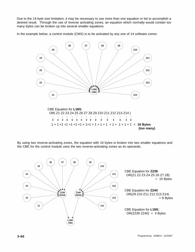
3-66 Programming 15088:H 12/23/97
Due to the 14-byte size limitation, it may be necessary to use more than one equation or list to accomplish adesired result. Through the use of reverse activating zones, an equation which normally would contain toomany bytes can be broken up into several smaller equations.
In the example below, a control module (CMX) is to be activated by any one of 14 software zones:
Z4
Z5
Z2
Z7 Z8
Z13
Z10
Z11
Z3
Z6
Z14Z1
Z9
Z12
L1M1CMX
By using two reverse-activating zones, the equation with 16 bytes is broken into two smaller equations andthe CBE for the control module uses the two reverse-activating zones as its operands.
Z4
Z5
Z2
Z7 Z8
Z13
Z10
Z11
Z3
Z6
Z14Z1
Z9
Z12
Z239RZON
Z240RZON
L1M1CMX
CBE Equation for L1M1: OR( Z1 Z2 Z3 Z4 Z5 Z6 Z7 Z8 Z9 Z10 Z11 Z12 Z13 Z14 )
1 + 1 +1 +1 +1 +1 +1 + 1+1 + 1 + 1 + 1 + 1 + 1 + 1 + 1 = 16 Bytes (too many)
CBE Equation for Z239: OR(Z1 Z2 Z3 Z4 Z5 Z6 Z7 Z8)
= 10 Bytes
CBE Equation for Z240: OR(Z9 Z10 Z11 Z12 Z13 Z14)
= 8 Bytes
CBE Equation for L1M1: OR(Z239 Z240) = 4 Bytes

Programming 15088:H 12/23/97 3-67
4.4 Cooperative Control-By-EventCooperative Control-By-Event equations pertain to reverse activated software zones on the AM2020/AFP1010 NOTI�FIRE�NETNOTI�FIRE�NETNOTI�FIRE�NETNOTI�FIRE�NETNOTI�FIRE�NET system only.
CCBE, like Control-By-Event (CBE), is used to provide a variety of responses based on various combinationsof events (initiating conditions). Where CBE programming controls the interaction between devices andsoftware zones within one AM2020/AFP1010, CCBE programming controls events between multiple panelson a NOTI�FIRE�NET system. For example, an initiating device in one panel turning on an output device ofanother panel through a reverse activated software zone. The formats and uses for CBE and CCBE are similarin many ways with the following exceptions:
• Only reverse activating software zones can be programmed with a CCBE equation.• CCBE equations can only be programmed for software zones from the AM2020/AFP1010 node that
the zones reside in. For instance, if a CCBE equation is to be programmed for software zone 23 ofnode 10 the user must program the equation on the AM2020/AFP1010 that is declared as node 10.
• CCBE can only use the AND(, OR(, and NOT( operands.• CCBE equations have a size limitation of 80 characters.
NOTEForward activating software zones can not have CCBE equations but can be used as operands in
other CCBE equations.
Each AM2020/AFP1010 has 240 software zones for both CBE and CCBE programming. Although there are240 software zones, only zones 2-240 can have CCBE equations associated with them. Since a zoneboundary must be declared, at least one of the software zones will be a forward activating zone and can nothave a CCBE equation associated with it. If Zone 1 is used as the zone boundary, then there are only 239zones left for CCBE programming.
It is possible for a reverse-activated software zone to have both a CBE and CCBE equation associated with it.If this occurs, the software zone will become active if either equation becomes active. The format for a CCBEequation is the same as a CBE equation. The operators for CCBE can only be AND(, OR(, and NOT(. Theoperands for CCBE are most often a zone with the format N(XXX)Z(YYY), where XXX is the node number forthe particular panel on the network and YYY is one of the 240 software zones available to CCBE programming.
4.5 The Null Control-By-EventThe simplest type of Control-By-Event is the Null, which means empty. For initiating devices, the Null isdenoted by entering ( ) as the Control-By-Event. In response to an alarm on a device programmed with aNull Control-By-Event, the AM2020/AFP1010 will do the following:
• Initiate a System Alarm condition (Alarm LED flashes, piezo sounds and the Form-C alarm contactson the CPU will be activated).
• Activate no control modules or software zones (no notification appliances will sound and no outputrelays will be activated due to the fact that there are no entries in the Control-By-Event for this initiatingdevice).
For Output Devices , the Null is denoted by entering OR( ) or ( ). Note: Entering ( is equivalent to enteringOR(. A control module programmed with a Null Control-By-Event will not be activated unless it is included inthe Control-By-Event of a software zone or initiating device.
Example - Resetting 4-wire Smoke DetectorsA control module is needed to reset power to 4-wire smoke detectors in an AM2020 or AFP1010 system. Thismodule must not be activated in response to an alarm condition. Rather, this module must only be activatedduring system reset. This can be accomplished by assigning the module a Null Control-By-Event and theSoftware Type ID PWRC (the control panel automatically resets modules with type PWRC upon systemreset).

3-68 Programming 15088:H 12/23/97
4.6 Programming Examples
OptionsThe example below illustrates three ways to accomplish the simple programming task of programming aNotification Appliance (control module) on SLC Loop 1 to indicate activation of an Initiating Device (smokedetector) also on SLC Loop 1.
SoftwareZone Z1
Type: FZON
ò ñ
Program the controlmodule with the
Control-By-Event
OR(Z1)
ñ
Solution A
Program the smokedetector with the
Control-By-Event:
(Z1)
ò
Solution C
Program the smokedetector with the
Control-By-Event:
(L1M1)
Program the controlmodule with the
Control-By-Event
OR(L1D1)
No Control-By-Event required forthe control module.
Solution B
No Control-By-Event required for
the smoke detector.
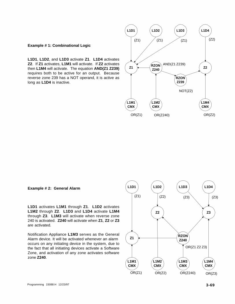
Programming 15088:H 12/23/97 3-69
Z2
L1D1
RZONZ240
L1D3 L1D4
RZONZ239
L1D2
L1M2CMX
L1M1CMX
Z1
L1M4CMX
Example # 1: Combinational Logic
L1D1, L1D2, and L1D3 activate Z1. L1D4 activatesZ2. If Z1 activates, L1M1 will activate. If Z2 activatesthen L1M4 will activate. The equation AND(Z1 Z239)requires both to be active for an output. Becausereverse zone 239 has a NOT operand, it is active aslong as L1D4 is inactive.
Example # 2: General Alarm
L1D1 activates L1M1 through Z1. L1D2 activatesL1M2 through Z2. L1D3 and L1D4 activate L1M4through Z3. L1M3 will activate when reverse zone240 is activated. Z240 will activate when Z1, Z2 or Z3are activated.
Notification Appliance L1M3 serves as the GeneralAlarm device. It will be activated whenever an alarmoccurs on any initiating device in the system, due tothe fact that all initiating devices activate a SoftwareZone, and activation of any zone activates softwarezone Z240.
OR(Z3)OR(Z240)
OR(Z1 Z2 Z3)
RZONZ240
L1D1
Z2
L1D3 L1D4
Z3
L1D2
L1M2CMX
L1M1CMX
Z1
L1M4CMX
L1M3CMX
OR(Z1) OR(Z2)
(Z2)(Z1) (Z3) (Z3)
(Z1)(Z1) (Z1) (Z2)
OR(Z2)
AND(Z1 Z239)
OR(Z240)OR(Z1)
NOT(Z2)
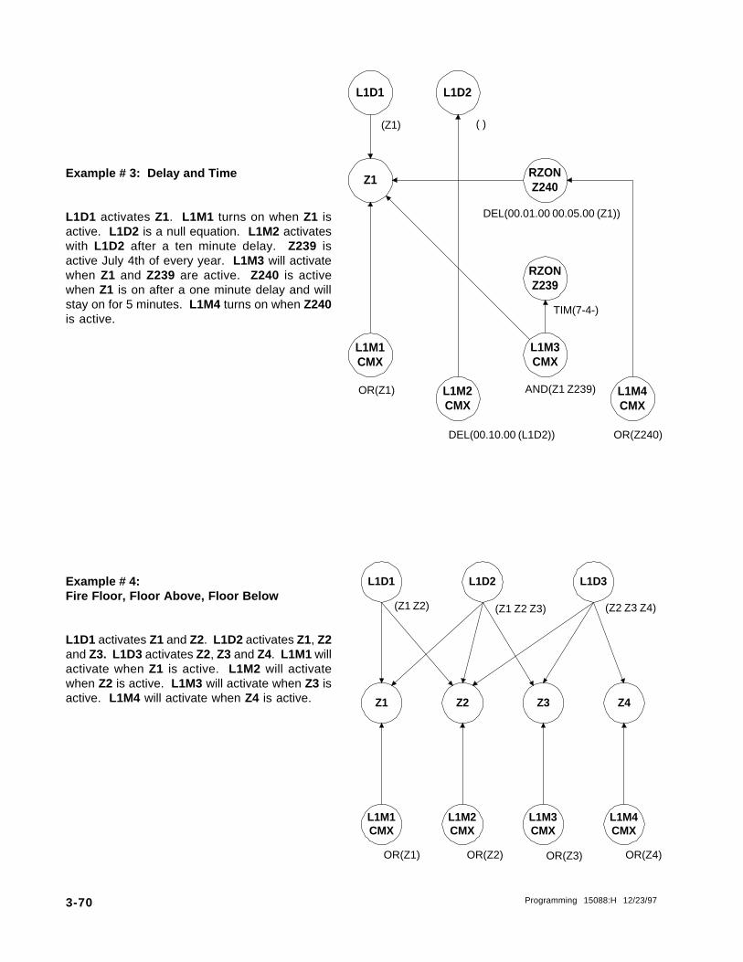
3-70 Programming 15088:H 12/23/97
Z4
L1D1
Z2
L1D3
Z3
L1D2
L1M2CMX
L1M1CMX
Z1
L1M4CMX
L1M3CMX
(Z1 Z2) (Z1 Z2 Z3) (Z2 Z3 Z4)
L1M3CMX
L1D1
RZONZ239
RZONZ240
L1D2
L1M2CMX
L1M1CMX
Z1
L1M4CMX
TIM(7-4-)
Example # 3: Delay and Time
L1D1 activates Z1. L1M1 turns on when Z1 isactive. L1D2 is a null equation. L1M2 activateswith L1D2 after a ten minute delay. Z239 isactive July 4th of every year. L1M3 will activatewhen Z1 and Z239 are active. Z240 is activewhen Z1 is on after a one minute delay and willstay on for 5 minutes. L1M4 turns on when Z240is active.
Example # 4:Fire Floor, Floor Above, Floor Below
L1D1 activates Z1 and Z2. L1D2 activates Z1, Z2and Z3. L1D3 activates Z2, Z3 and Z4. L1M1 willactivate when Z1 is active. L1M2 will activatewhen Z2 is active. L1M3 will activate when Z3 isactive. L1M4 will activate when Z4 is active.
(Z1)
AND(Z1 Z239)
DEL(00.10.00 (L1D2))
( )
OR(Z4)OR(Z3)OR(Z2)OR(Z1)
DEL(00.01.00 00.05.00 (Z1))
OR(Z240)
OR(Z1)
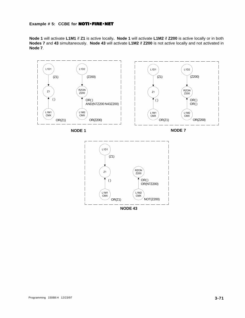
Programming 15088:H 12/23/97 3-71
Example # 5: CCBE for NOTI�FIRE�NETNOTI�FIRE�NETNOTI�FIRE�NETNOTI�FIRE�NETNOTI�FIRE�NET
Node 1 will activate L1M1 if Z1 is active locally. Node 1 will activate L1M2 if Z200 is active locally or in bothNodes 7 and 43 simultaneously. Node 43 will activate L1M2 if Z200 is not active locally and not activated inNode 7 .
L1D1
Z1
L1M1
CMX
L1D2
RZON
Z200
L1M2
CMX
(Z1) (Z200)
OR(Z1) OR(Z200)
( ) OR( )AND(N7Z200 N43Z200)
NODE 1
(Z1) (Z200)
OR(Z1) OR(Z200)
( ) OR( )OR( )
L1D1
Z1
L1M1
CMX
L1D2
RZON
Z200
L1M2
CMX
NODE 7
NODE 43
(Z1)
OR(Z1) NOT(Z200)
( ) OR( )OR(N7Z200)
L1D1
Z1
L1M1
CMX
RZON
Z200
L1M2
CMX

3-72 Programming 15088:H 12/23/97
Programming for Dual Stage Alert/Evacuation operation (for use in Canada only)
An XPC-8 Notification Appliance Circuit module can be configured for Dual Stage Alert/Evacuation operation.Under this mode of operation each circuit operates in one of two stages: alert or evacuation. In the alert stagethe notification appliance circuit pulses at 20 PPM (pulses per minute). In the evacuation stage the circuitpulses at 120 PPM. When configured this way, each notification appliance circuit has two addressesassociated with it. Refer to the XP Series Transponder Manual for additional information.
The first address is the control address. Activating this point (through its Control-By-Event programming) willturn the notification appliance circuit on. This point uses the Software Type ID CON.
The second address is the stage selection address. This point decides what state an active notificationappliance circuit will be in. Activating this point will put the notification appliance circuit into evacuation mode.If this point is not activated the circuit will be in alert mode. This point uses the Software Type ID FORC.
NOTEIf an unacknowledged circuit is in alert mode for more than five minutes, all activated circuits on the
XPC-8 will change to the evacuation pulse rate.
Section FiveDual Stage Alert/Evacuation