nanoparticles for cancer cell detection - sig.ias.edu 5 - biomems nano cancer detection... ·...
TRANSCRIPT

BioMEMS and Nanoparticles for the
Detection and Treatment of Cancer
Wole Soboyejo
Princeton Institute of Science and Technology of Materials (PRISM)
and
Department of Mechanical and Aerospace Engineering
Princeton University

Acknowledgments
• Financial Support - NSF and Princeton University
• Scientists – Jikou Zhou, Karen Malatesta
• Students - C. Milburn, S. Mwenifumbo, R. Weissbard, L. Ionescu, L. Hayward, O. Bravo, J. Meng, R. Bly, W. Moore, S. Agonafer, B. Silverman, J. Chen, M. Bravo, Emily Paetzell, Chris Theriault, Yusuf Oni
• Colleagues - Challa Kumar (CAMD), Josef Hormes (CAMD), Carolla Leuschner (Pennington), Jeff Schwartz (Princeton), Julie Young (Princeton), Aboubaker Beye (Cheikh Anta Diop), Tom Otiti (Makerere), Warren Warren (Princeton), Jeff Schwartz (Princeton), Mona Marei (Alexandria), Jack Ricci (NYU), Mingwei Li (Spectra Physics), Alberto Cuitino (Rutgers)
• MRI Technician - Silvia Cenzano (Princeton)

Background and
Introduction• Richard Feynmann – There’s lots
of room at the bottom….(1961 APS talk)
• Several people could benefit from implantable or injectable systems for class detection and treatment
• This talk examines two types of small structures for cancer detection
–BioMEMS

Why the Focus on Cancer?• Several people suffer from cancer – either directly or
through contact with someone that has cancer
• The biggest problem is really one of early detection –existing methods of detection are limited in spatial resolution
• The other major problem is the severe effect of existing cancer treatment methods e.g. radiation and chemotherapy (localized theraputics to be addressed in the next class)
• This class presents some new ideas on cancer detection
- BioMEMS for the detection of cancer
- Magnetic nanoparticles for cancer detection

Introduction to BioMEMS Systems
Drug Delivery System Implantable Blood Pressure Sensor
BioMEMS structures are micron-scale devices that are used in biomedical or biological applications
At this scale, a wide range of devices are being made (e.g. pressure sensors, drug delivery systems, and cantilever detection systems)
Explosive growth in emerging markets – civilian and military applications expected to reach multi-billion dollar levels

MEMS-Enhanced Trileaflet
Valve

Atherosclerosis
• Atherosclerosis is the hardening and narrowing of blood vessels caused by buildup of plaque
• Plaque is made up of cholesterol, calcium, and other blood components that stick to the vessel walls
• When plaque bursts, blood tends to clot, thus creating more blockage

Biocompatibility of Silicon MEMS SystemS
500 nm
Coated BioMEMS Structure 500 nm Ti Layer on Si
Si is not the most biocompatible material
Can be made biocompatible through the use of polymeric or Ti coatings.
Polymeric coatings used on Si drug release systems.
Ti coating approaches are also being developed.
Si
Ti
Ti
Ti
Ti

SURFACE CHEMISTRY – CELL SPREADING
Si - 50 nm Titanium
Si
30 minutes 60 minutes 120 minutes
HOS Cells

SHEAR ASSAY MEASUREMENT OF CELL ADHESION
Shear Flow Schematic
Cell Detachment
Shear stress for detachment is given by
Where Q - flow rate & m -dynamic
viscosity
Considering initial onset of detachment to correspond to “adhesion” strength:
t = 70 Pa Polystyrene (PS)
t = 81 Pa Ti Coated PS
2wh
6Qmt =

Digital Image Correlation
Global Digital Image Correlation (GDIC) can be effectively utilized to characterize the cell
deformation pattern by sequential correlating the images recorded during the assay shear test.
The deformation mapping between these two images is obtained by a multi-variable minimization
which conducted on a constrained system determined by the mesh
Due to the severe deformations experienced by the cell during the assay test, a remeshing step is
required to preserve the mesh quality
.
Initial Final Final

Cellular Displacement
Subjected to Shear Flow
Higher mobility was observed at the rear edge (region b),
compared to the front edge subjected to shear flow
1.2 sec 2.4 sec
3.6 sec

Cellular Strain Subjected to
Shear Flow
The shear strains in cytoplasm increased
more significantly than those obtained in the
nucleus during the shear assay experiment
1.2 sec
2.4 sec
3.6 sec

Viscoelastic Modeling
E
1
2
Time
Time
Stress
Strain

Obtained Shear Moduli and
Viscosities
The fact that the nucleus is more rigid than the cytoplasm can explain why the nucleus
deforms less than the cells when subjected to shear flow in the current study, or when the
substrate is stretched.

Cellular Adhesion Apparatus
Interaction between cell-cell and cell
extracellular matrix are by specific
contacts of adhesion molecules
Cells in culture often form focal adhesion
sites, a specialized and discrete region of
the plasma membrane
Cell viscoelastic deformability is
determined largely by the composite
shell envelope and cell cytoskeleton

Surface Preparation
• Polishing
• AFM
• RGD-Coating
C-D
GR
N
O
OO
TiO2
Surface
OO
C
P
O
O
O
H
RGD coatedControl
Polished Surfaces
100nm
50nm
0nmRoughness
5 nm
20 mm

Interfacial Shear Strength
Measurement
0.00
20.00
40.00
60.00
80.00
100.00
1
Incubation Time (hr)
Av
era
ge
Sh
ea
rin
g S
tre
ss
(P
a) Control
AP coated
RGD coated
Control
AP coated
RGD coated

Effects of RGD Coating• Short term effects of RGD coating:
– Increased spreading and cellular adhesion
– Increased protein organization of the cytoskeleton
• Previous studies indicate long term effects
(mineralization):
• Clinical studies very promising
12mm 12mm
Control - 7 day RGD - 7 day
Stained for actin (red), nucleus (blue), hydroxyapatite (green

Micro-Groove Geometry and
Cell/Surface Interactions
• Cells can undergo contact guidance when in contact with micro-
grooved geometries
• This depends on the size of the grooves relative to the size of the cells
• Contact guidance has implications for wound healing and scar tissue
formation
100 mm
Cell
12 mm Micro-Grooves2 mm Micro-Grooves

100 mm
8 mm Grooves 12 mm Grooves
Laser Textured Surfaces - Cell/Surface
Interactions
100 mm
MC3T3 Cells - 2 Days MC3T3 Cells - 2 Days

Polished Al2O3 Blasted
Surface Texture - Cell/Surface Interactions
100 mm100 mm
MC3T3 Cells - 2 Days MC3T3 Cells - 2 Days

Surface Texture – UV Laser Textured Surfaces IF
Staining
11 mm Laser-Grooved Surface
HOS 2 Days - Vinculin HOS 2 Days - Vinculin
Polished Surface

Surface Texture – UV Laser Textured Surfaces
Cell/Surface Interactions
HOS cells cultured on groove set 1 (10 mm spacing) lie within
micro-grooves – high level of contact guidance.
HOS cells cultured on groove set 5 (50 mm spacing) display a
moderate level of contact guidance – some cells span across
plateau regions.
Cells on Plateau RegionsCells on Plateau Regions
Groove Set 1 (10 mm Spacing) Groove Set 5 (50 mm Spacing)

3-D View (Horizontal, 10micron)

Engineered Tissue
Immunoisolation/
Compatibility
Scaffolds
Upscaling
Bioreactor Design
Cells
Preservation


View under a microscope at high magnification
Use a biochemical assay to reveal cells
Use a bioMEMS cell detector e.g. a cantilevered MEMS structure
External imaging system, e.g. MRI
A FEW METHODS FOR DETECTING CANCER
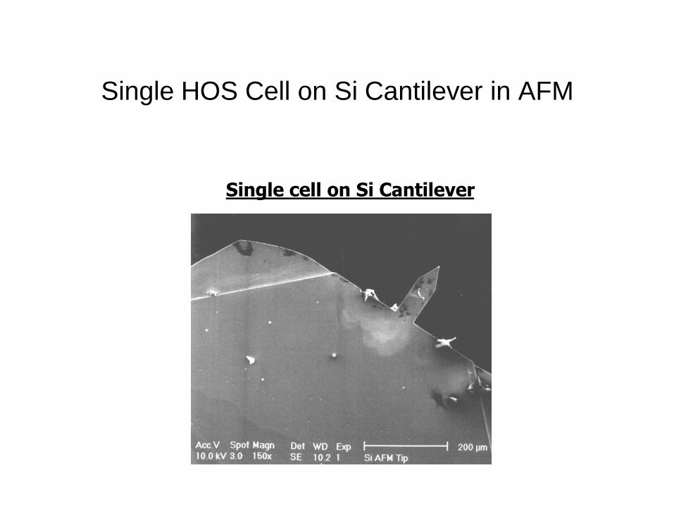
Single HOS Cell on Si Cantilever in AFM
Single cell on Si Cantilever

CELL DETECTION ON CANTILEVER
Cantilever No. 17
Initial Frequency: 263.36 KHz
Spring constant: 44.86 N/m
Final Frequency: 261.59 KHz
Difference: 1.77 KHz
Outline of cantilever
Attached Cells Tip
Cantilever shows the presence of two cells
one attached near the tip, the other is at the base of the cantilever

Antibody/Antigen Interactions
• Antibody/antigen interactions cause surface stresses to develop
• These surface stresses are the result of new conformations of
molecular structures at the surface
• Interactions between Vimentin antibodies and antigens gives rise
to surface stress and cantilever deflection

Cantilever Deflection data

THE FUTURE OF CANTILEVERED BIOMEMS
STRUCTURES – BIOMOLECULAR DETECTION
Microcantilever Array
Research will lead to future cantilevered bioMEMS structures
Devices may be resonating devices for improved sensitivity
However, non-resonating devices can also be used
Multifunctional structures emerging with multiple cantilevers
DNA
Folic Acid
Antibodies
PackagingFunctionalized Cantilever
Y Y Y

Our Approach to Early Cancer
Detection and Treatment!
CAMD
LP conjugates
LP conjugates
LP conjugatesLP conjugates
LP conjugates
LP conjugates LP conjugates
LP conjugates
LHRH
LHRHLHRH
LHRH
LHRH
LHRH LHRH
LHRH
Magnetic core
Polymer shell
with lytic peptide
conjugates

CAMD
Wet Chemical Synthesis of Nano-particles
Metallic, polymeric and metal-polymer
Nano-particles using bottom-up approaches
Novel Micro reactor technology for scale-up and
controlled synthesis
Synchrotron radiation based X-ray absorption
Spectroscopic characterization
Capability to attach bio-molecules
In-Vitro Experiments
• Studied attachment of nano-particles in
cell culture experiments
• Studied effects of temperature and time
• Imaging done using TEM after fixing
• Studies conducted on breast cancer cells
with LHRH receptors
– Unconjugated nanoparticles
– LHRH-coated nanoparticles

TEM Images of Breast Cancer
Cells (Control)

SPION Uptake - 37 C for 30
Minutes

LHRH-SPION Uptake - 37 C for
3 Hours
• MNPs-LHRH, 37 C, 3
Hr
• Note encryption
process by which
cells attach
• Engulfed cells carried
within the cell
• Excreted or egested
within 30 days

In-Vivo Experiments
• Mice injected in 4 different ways:
1. LHRH nanoparticles
2. saline solution
3. nanoparticles
4. LHRH nanoparticles but with
mice that do not contain
breast tumor

Materials Characterization of
Organs (TEM and Histology)
Organs obtained:
– breast or prostate tumor
– Kidney
– Lung
– Liver
Ensure that the nanoparticles do not accumulate in other major organs.

SPION/SPION-LHRH in Breast Tumor
SPION in Tumor LHRH-SPION in Tumor
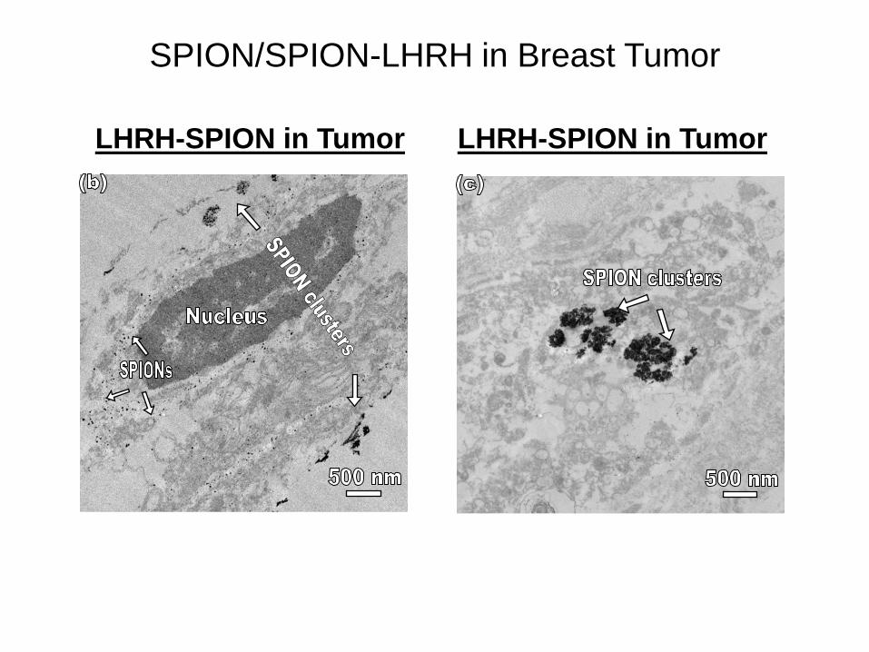
SPION/SPION-LHRH in Breast Tumor
LHRH-SPION in Tumor LHRH-SPION in Tumor

SPION in Lung
SPION in Lung LHRH-SPION in Lung

SPION/SPION-LHRH in Liver
SPION in Liver LHRH-SPION in Liver

LHRH-SPION in Kidney
SPION in Kidney LHRH-SPION in Kidney

0
10
20
30
40
50
60
70
Tumor Lung Liver Kidney
Iro
n C
on
ten
t (%
)
0
10
20
30
40
50
60
Tumor Lung Liver Kidney
Iro
n C
on
ten
t (%
)
Biological Distribution of SPIONs
LHRH-SPION in Mouse SPION in Mouse

Targeted Destruction of Prostate Cancer in
Balb/c athymic nude mice
CAMD
PC-3.luc Xenograft bearing male nude
mice were used
LHRH bound nanoparticles effectively
bind to tumor
Use of Nano-LHRH results in accumulation
68% of nanoparticles in tumor
Distribution of iron in other tissues is
being mapped

Fundamentals of Magnetic
Resonance Imaging (MRI)
• Hydrogen atoms in water have a
property called spin
• MRI generates a magnetic pulse that
aligns all of the spins in a certain
direction
• The magnetic resonances of the nuclei
will cause differences in how they return
to their normal spin state
• The MRI machine records the energy
released as they realign at different
times and generates an image
• A set of images are generated at certain
small time intervals after the pulse
sequence

Initial MRI Experiments:
Cherry Tomato and Grape
• Injected grapes with saturated
saline solution of nanoparticles
• Observed contrast at the location
of the injection (nanoparticles)
The iron creates a magnetic field in the water, thus creating a blind spot (dark) for the MRI

T2 Images of Tumors – Contrast
Enhancement Due to LHRH-MNPs

Summary and Concluding Remarks
• Overview of some recent work on bioMEMS and bio-nanotechnology for disease (mostly cancer) detection and treatment
• Nanoscale biocompatible titanium coatings and micro-grooves promote adhesion and contact guidance on bioMEMS surfaces
• In-vitro and in-vivo TEM reveal stages of specific nanoparticle attachment and encryption
• LHRH-coated magnetite particles provide opportunities for early MRI detection and treatment of breast & prostate cancer
• PNIPA- Fe3O4 systems can be used for hyperthermia and controlled drug release (temperature controlled by MNP concentration and H)