narrow-band, narrow-field-of-view raman lidar with combined day and night capability for...
TRANSCRIPT
l
faqvcfc
Narrow-band, narrow-field-of-view Raman lidar withcombined day and night capability for troposphericwater-vapor profile measurements
Scott E. Bisson, John E. M. Goldsmith, and Mark G. Mitchell
We describe a high-performance Raman lidar system with combined day and night capability for tropo-spheric water-vapor profile measurements. The system incorporates high-performance UV interferencefilters and a narrow-band, dual-field-of-view receiver for rejection of background sunlight. Daytimeperformance has been demonstrated up to 5 km with 150-m vertical and 5-min temporal averaging. Thenighttime performance is significantly better with measurements routinely extending from 10 to 12 kmwith 75-m range resolution and a 5-min temporal average. We describe design issues for daytimeoperation and a novel daytime calibration technique. © 1999 Optical Society of America
OCIS codes: 280.0280, 280.3670, 300.6450.
m
ulho
1. Introduction
Raman lidar is a powerful, established technique forthe continuous measurement of nighttime water-vapor profiles ~in clear skies or up to the lowest cloudevel! with high spatial and temporal resolution.1–4
The technique operates by transmitting a pulse oflaser light at a fixed wavelength and simultaneouslyrecording signals at wavelengths corresponding tothe inelastic rovibrational Raman shifts of nitrogen~2331 cm21! and water vapor ~3657 cm21!. Theelastic-backscattered signals corresponding to Ray-leigh and aerosol scattering are usually also detected.The choice of excitation wavelength is somewhat ar-bitrary but excitation outside the solar-blind region~wavelengths longer than 290 nm! is usually pre-erred. By taking ratios of the water-vapor Ramannd nitrogen Raman signals, a range-dependentuantity that is proportional to the absolute water-apor concentration is obtained. A range-dependentorrection factor is usually applied to account for dif-erential Rayleigh and aerosol scattering. If the ex-itation wavelength is below approximately 290 nm
The authors are with the Diagnostics Research Division, SandiaNational Laboratories, 7011 East Avenue, P.O. Box 969, Liver-more, California 94551-5149. The email address for S. E. Bissonis [email protected].
Received 31 July 1998; revised manuscript received 13 Novem-ber 1998.
0003-6935y99y091841-09$15.00y0© 1999 Optical Society of America
then tropospheric ozone can be a serious problem.Tropospheric ozone not only attenuates the signalsbut, depending on the choice of excitation wave-length, the backscattered Raman signals may also bedifferentially attenuated, resulting in a range-dependent bias in the water-vapor determination.Typically, ozonesondes are used for measuring theozone profile but the backscattered Raman signalscan also be used. The wide daily variability of ozonerequires that the ozone profile be determined for eachwater-vapor measurement.
Raman lidar has routinely demonstrated the abil-ity to measure nighttime water-vapor profilesthroughout most of the troposphere with highaccuracy.1–4 The influence of solar radiative forcing,and the need for continuous data records, providesstrong motivation for similar daytime capabilities.There are relatively few water-vapor Raman lidarsystems that operate in the daytime, and for thosethat do the daytime performance is usually signifi-cantly degraded from the nighttime performance.In a previous paper we presented results from a Ra-man lidar system that was developed at Sandia Na-tional Laboratories for the U.S. Department ofEnergy ~DOE! Atmospheric Radiation Measure-
ents ~ARM! program.4 The system currently re-sides at the DOE Cloud and Radiation Testbed~CART! facility in north central Oklahoma and is
sed to acquire critical meteorological and climato-ogical data for the DOE ARM program. Operationas been demonstrated with this system continu-usly both day and night for several days. Daytime
20 March 1999 y Vol. 38, No. 9 y APPLIED OPTICS 1841

pmtogipsti
ptre
1
water-vapor measurements up to 5 km have beendemonstrated routinely with this system. The de-sign of the CART Raman lidar was based on an ear-lier Raman lidar test-bed system that was alsodeveloped at Sandia. Although the configurationand performance of the CART Raman lidar were pre-sented in detail in Ref. 4, there was little discussionon the design issues of combined day and night ca-pability for Raman lidar. In this paper we discussdesign issues for a daytime Raman lidar as applied tothe Sandia Raman lidar test-bed.
The central problem in the development of adaytime-capable Raman lidar is the detection of therelatively weak backscattered Raman signal againstthe large solar background. There are several ap-proaches to this problem: solar-blind operation inwhich the system operates at wavelengths below 290nm where the sky is effectively black; narrow-band,narrow-field-of-view ~FOV! operation; and a hybridapproach. For all these approaches there are usu-ally three wavelengths involved: the outgoing laserexcitation wavelength and two backscattered signalsat longer wavelengths corresponding to the rovibra-tional Raman shifts of nitrogen and water vapor.Although operation in the solar-blind region of thespectrum effectively reduces the solar background,attenuation of the laser beam and the backscatteredRaman radiation by tropospheric ozone is a seriousproblem. There are examples of solar-blind Ramanlidars operating in remote regions where the tropo-spheric ozone concentration and attenuation wereminimal which allowed daytime water-vapor mea-surements through much of the troposphere. How-ever, for most geographical locations attenuation bytropospheric ozone is a problem.
Solar-blind Raman lidar systems operating at 248and 266 nm have been used to make vertical daytimewater-vapor measurements in the 1–2-km range.5,6
This range can be extended by operating at a moreoptimum wavelength. The selection of the optimumwavelength is based on a compromise between ab-sorption of the transmitted and return signals byintervening ozone and reduction of the backgroundsky radiance. The transmitted wavelength is opti-mized only in the sense that it places the water-vaporRaman return near the ozone absorption edge. Theoptimum wavelength depends on the solar back-ground level ~solar angle, time of year, etc.! and onthe ozone concentration and so is variable. Indepen-dent model calculations suggest that the optimumtransmitted wavelength for daytime operation isroughly 255–265 nm.7 This wavelength range
laces the water-vapor Raman return at approxi-ately 281–293 nm, which is near the ozone absorp-
ion edge at 295 nm. Wavelength-optimizedperation also poses another problem in that directeneration of high-power tunable UV laser radiations difficult. Instead, nonlinear frequency conversionrocesses such as second-harmonic generation andum-frequency mixing are frequently used to convertunable visible radiation to the UV, a process that isnefficient. An alternate method is Raman shifting.
842 APPLIED OPTICS y Vol. 38, No. 9 y 20 March 1999
In this method, the output of a laser is typically fo-cused into a long ~;1-m!, high-pressure cell contain-ing a gas such as hydrogen. The output of the cellconsists of discrete wavelengths above and below theexcitation wavelength. This technique has been ex-plored for use in generating the near-optimum wave-length of 263 nm using a nitrogen Raman-shiftedkrypton fluoride excimer laser.8 Unfortunately, theconversion efficiency of the 248-nm excimer radiationto the near-optimum wavelength of 263 nm was low.
In the narrow-band, narrow-FOV approach, thebackground skylight is reduced by narrowing the re-ceiver FOV while operating the laser outside thesolar-blind region ~wavelengths longer than approx-imately 290 nm!, thus avoiding the ozone attenuation
roblem. Narrow-band detection is also employedo reduce the solar background without substantiallyeducing the weak Raman return signals. Ansmannt al.3 have used this approach and have obtained
daytime water-vapor profiles up to 2.5 km with 180-mrange resolution using integration times of approxi-mately 15 min. We developed a high-performance,narrow-band, narrow-FOV Raman lidar capable ofdaytime water-vapor measurements up to 5 km ormore depending on conditions. One of the problemsintroduced by narrow-FOV operation is that theshort-range performance suffers because of poor spa-tial overlap of the laser beam and telescope FOV atlow altitudes. To overcome this problem, we devel-oped a dual-FOV receiver that provides higher dy-namic range and substantially better spatial overlapof the laser beam and telescope FOV. The weakhigh-altitude signals are detected by a narrow-FOVchannel, and the low-altitude signals are detected bya wide-FOV channel, in which the stronger signallevels compensate for the higher background level.Narrow-band detection is achieved through use ofhigh-performance UV interference filters. It is pos-sible that a further reduction of the solar backgroundcould be achieved through use of a polarizer placed inthe receiver. At high latitudes or large solar anglesthe solar background is highly polarized because ofRayleigh scattering, so this technique may be useful.However, at lower latitudes with larger solar anglesthe solar background is less polarized so the useful-ness of this technique may be limited. In this tech-nique the polarization angle of the transmitted beamand the receiver must also be adjustable.
Although there is a great deal of flexibility in choos-ing the wavelength for a nonsolar-blind Raman lidar,there are important laser repetition rate consider-ations for daytime operation. For nighttime opera-tion the performance is relatively independent oflaser repetition rate until the received signal reacheseither the dark current limit of the detector or thebackground light levels. Figure 1 shows a compar-ison of predicted nighttime range for a signal-to-noise~SyN! ratio of 10 as a function of integration time.These calculations assumed an excitation wave-length of 308 nm, a receiver diameter of 0.7 m, areceiver spectral bandwidth of 0.4 nm, and a FOV of0.2 mrad. The photomultiplier tube ~PMT! dark

Iqtcepwi
u
counts were defined to be 1000 countsys, which isapproximately five times larger than our actual darkcounts. For counting times of the order of a minuteor less it can be seen from the calculations that theperformance is a function only of average power. Inthe daytime, however, the performance is no longerindependent of average power but becomes a functionof laser-pulse energy. For a constant average powerit is therefore advantageous to use a low repetitionrate, high-pulse energy laser. Lowering the repeti-tion rate at constant average power reduces the in-tegration time and hence the integrated solarbackground while the integrated laser signal remainsconstant. Thus the SyN ratio is greatly improved.Figure 2 shows a comparison of predicted daytimeperformance for three systems with different pulseenergies but with fixed average power ~2 W!. Thedetails of this model are given in Ref. 7.
Fig. 1. Comparison of predicted nighttime performance for threedifferent pulse energies and constant average power. The perfor-mance is relatively independent of pulse energy until the signallevels approach either the detector dark current or the backgroundskylight levels ~moonlight, city lights, etc.!.
Fig. 2. Comparison of daytime Raman lidar performance forthree different pulse energies and fixed average power. In thedaytime, a low repetition rate, high-pulse energy system is pre-ferred.
In a third approach, it is possible that a combina-tion of wavelength optimization and narrow-band,narrow-FOV operation could be employed, but to ourknowledge this has not been attempted.
As part of the DOE ARM program, we developed ahigh-performance dual-FOV, narrow-band Raman li-dar system capable of both daytime and nighttimeoperation. This system has demonstrated night-time water-vapor measurements up to 12 km in a5-min average with 75-m range resolution and water-vapor concentrations of the order of 0.1–0.2 g watervaporykg dry air ~hereinafter referred to as gykg!.n the daytime, the performance is lower but stilluite acceptable with measurements ranging from 3o 5 km depending on conditions with water-vaporoncentrations of the order of 1 gykg. There are sev-ral advantages to the narrow-band, narrow-FOV ap-roach. First it is not necessary to optimize theavelength, thus allowing use of nontunable ~or lim-
ted tunability! high-power UV sources such as exci-mer or frequency tripled YAG sources. And second,the transition from daytime to nighttime operation iseasily achieved simply by opening the receiver FOVslightly and installing a wider bandpass interferencefilter in the water-vapor channel. With only a smallcompromise in nighttime performance, the onlychange needed is the addition of a neutral densityfilter in the water-vapor channel during daytime op-eration. Finally, because the excitation and re-ceived wavelengths are chosen to be well outside thesolar-blind region, there are no corrections for differ-ential ozone attenuation. This approach does, how-ever, require a well-collimated laser beam and asomewhat narrow bandwidth ~,0.1 nm!. In the re-mainder of this paper we describe the Sandia Ramanlidar test-bed system with an emphasis on daytimeoperational issues. Measurements of daytime tro-pospheric moisture made at Sandia in Livermore,Calif., and at the ARM CART site in Oklahoma arepresented.
2. Instrument
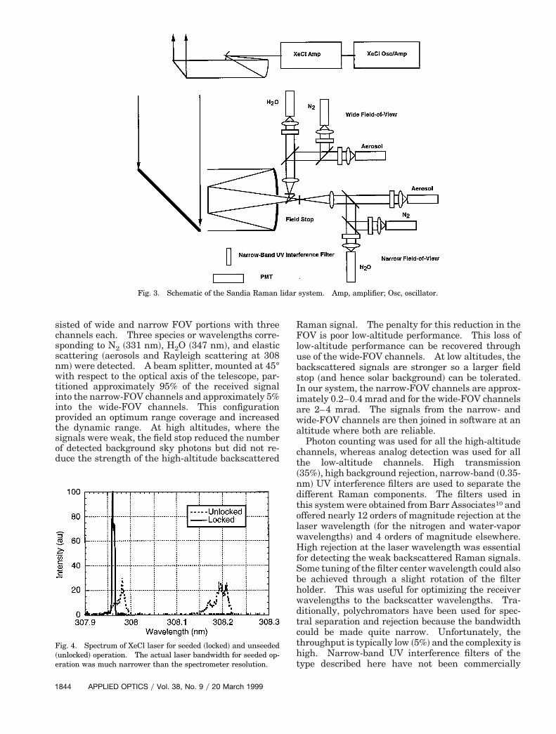
Figure 3 shows a schematic of the Sandia lidar sys-tem. The transmitter is a Lambda Physik LPX 150T injection-locked, tunable XeCl laser. Injectionlocking was essential for reducing the divergence andlinewidth of the laser beam.9 The output of this la-ser was then further amplified by a second XeClsingle-pass amplifier yielding approximately 200–250 mJ at 200 Hz in a 20-ns pulse. Higher outputenergies were possible, but for increased gas lifetimeand to avoid optical damage the system was run con-servatively at these energies. Figure 4 shows a typ-ical spectrum of the laser for seeded ~locked! and
nseeded ~unlocked! operation. The actual laserbandwidth could not be fully resolved with the spec-trometer used for this measurement. Here the laseris shown tuned to the blue portion of the spectrum.
The receiver system was based around a 0.76-m f4.5 Dall–Kirkham telescope with a FOV that could bereduced to 0.2 mrad, which is comparable with thelaser beam divergence. The detection system con-
20 March 1999 y Vol. 38, No. 9 y APPLIED OPTICS 1843
snwtiiptsod
RFlubsIiawa
ct~n
HfSbhwdtctht
1
sisted of wide and narrow FOV portions with threechannels each. Three species or wavelengths corre-sponding to N2 ~331 nm!, H2O ~347 nm!, and elasticcattering ~aerosols and Rayleigh scattering at 308m! were detected. A beam splitter, mounted at 45°ith respect to the optical axis of the telescope, par-
itioned approximately 95% of the received signalnto the narrow-FOV channels and approximately 5%nto the wide-FOV channels. This configurationrovided an optimum range coverage and increasedhe dynamic range. At high altitudes, where theignals were weak, the field stop reduced the numberf detected background sky photons but did not re-uce the strength of the high-altitude backscattered
Fig. 3. Schematic of the Sandia Raman
Fig. 4. Spectrum of XeCl laser for seeded ~locked! and unseeded~unlocked! operation. The actual laser bandwidth for seeded op-eration was much narrower than the spectrometer resolution.
844 APPLIED OPTICS y Vol. 38, No. 9 y 20 March 1999
aman signal. The penalty for this reduction in theOV is poor low-altitude performance. This loss of
ow-altitude performance can be recovered throughse of the wide-FOV channels. At low altitudes, theackscattered signals are stronger so a larger fieldtop ~and hence solar background! can be tolerated.n our system, the narrow-FOV channels are approx-mately 0.2–0.4 mrad and for the wide-FOV channelsre 2–4 mrad. The signals from the narrow- andide-FOV channels are then joined in software at anltitude where both are reliable.Photon counting was used for all the high-altitude
hannels, whereas analog detection was used for allhe low-altitude channels. High transmission35%!, high background rejection, narrow-band ~0.35-m! UV interference filters are used to separate the
different Raman components. The filters used inthis system were obtained from Barr Associates10 andoffered nearly 12 orders of magnitude rejection at thelaser wavelength ~for the nitrogen and water-vaporwavelengths! and 4 orders of magnitude elsewhere.
igh rejection at the laser wavelength was essentialor detecting the weak backscattered Raman signals.ome tuning of the filter center wavelength could alsoe achieved through a slight rotation of the filterolder. This was useful for optimizing the receiveravelengths to the backscatter wavelengths. Tra-itionally, polychromators have been used for spec-ral separation and rejection because the bandwidthould be made quite narrow. Unfortunately, thehroughput is typically low ~5%! and the complexity isigh. Narrow-band UV interference filters of theype described here have not been commercially
system. Amp, amplifier; Osc, oscillator.
lidar
truFw
Table 1. Sandia Raman Lidar Specifications
available until recently. These filters are the key tobuilding a high-performance daytime system.
For both photon counting and analog detectionmodes, ten-stage Phillips XP 2978 tubes were used.The tube bases were optimized for either pulse ~pho-on counting! or analog modes. Tube voltagesanged from 21200 V on the analog aerosol channelp to 21600 V for the analog water-vapor channel.or the photon-counting channels the tube voltagesere all set at 21450 V. The pulses from the
photon-counting tubes were 5 ns in duration and ap-proximately 10-mV peak. A 310 amplifier was usedto boost the signal levels into a 300-MHz PhillipsScientific discriminator. The signals were then fedinto a DSP Technology, Inc. Model 2090S, 100-MHzmultichannel CAMAC scaler. Although the systemwas rated at 100 MHz, the photon count rates wererestricted through use of neutral density ~ND! filtersto 20 MHz or less. At these rates, photon pileupcould be corrected using the method of Whiteman et.al.1 The photon pileup correction was determinedby inserting an additional ND 1 filter into each of thechannels and recording range-resolved returns. Atthese levels photon pileup was negligible. This mea-surement was then compared with the full-strengthmeasurement from which a pileup correction could bederived. Because the photon pileup was not too se-vere, the following relation could be used to deter-mine the corrected signal:
Ncorr 5Nmeas
1 2 ~rNmeasyT!,
where Nmeas is the actual measured range-resolvedsignal counts for a given channel, Ncorr is the cor-rected signal, r is the counter dead time, and T is thetotal counting time ~bin width times number ofshots!. The counter dead time was determined to be20.7 ns, which corresponds to a count rate of 48 MHzthat is consistent with the maximum count rate of100 MHz.
For analog detection the signals were first ampli-fied by a factor of 500 and filtered for a bandwidth of
Transmitter
Laser
XeCl ExcimerOscillator, Two
Amplifiers
Wavelength 308 nm ~XeCl! DEnergyypulse 250 mJ fRepetition rate 200 Hz CBandwidth 3 pm FDivergence ;0.2 mrad RBeam expansion Off axis 3 5 S
D
2 MHz. The signals were then digitized by 12-bit,10-MHz DSP Technology, Inc. CAMAC digitizers.We found that analog detection is difficult because ofthe high level of electrical noise and transients fromthe laser and CAMAC crate. A solution to this prob-lem is to attenuate the low-altitude wide-FOV signalsand use photon counting. This approach is cur-rently being used in CART Raman lidar.4 Table 1summarizes the specific instrument characteristics.
3. Results
A daytime measurement made with this system atthe DOE CART site in Oklahoma is shown in Fig. 5.These data were acquired with an average laser-pulse energy of 220 mJ at 200 Hz. For this mea-surement the integration time was 10 min with 75-mvertical resolution. The measurement was madeunder spring conditions ~April 1995! in the late after-noon, so the solar angle was around 30 deg from thehorizon. Because of noise problems with the low-altitude analog-to-digital system, the profile displaysonly the narrow-FOV photon-counting data. Thephoton counters used in this system were rated at
Receiver
elescope Cassegrain ~Dall–Kirkham!
eter 0.76 mber 4.5
nel bandpass 0.4 nmof view Dual ~0.4 mrad, 4 mrad! typicale resolution 75 m ~0.5 ms!es Rayleighyaerosol ~308 nm!
Water vapor ~347 nm!Nitrogen ~331 nm!
tion Analog 12-bit at 2 MHzPhoton counting at 20 MHz
Tubes: ten-stage PMT’s
Fig. 5. Comparison of a daytime Raman lidar water-vapor profilemeasurement with a radiosonde. The lidar data are a 10-minaverage with 75-m vertical resolution.
T
iam-numhanieldangpeci
etec
20 March 1999 y Vol. 38, No. 9 y APPLIED OPTICS 1845

1
100 MHz but suffered from severe photon pileup inthe presence of large solar backgrounds ~60-MHzcount rate typical!, so ND ~1.0! filters were placed inboth the water-vapor and the nitrogen Raman chan-nels to reduce the background photon count rate toapproximately 6 MHz. Although this reduced thebackground count rates to manageable values it alsoreduced the received laser signal by the sameamount. The data in Fig. 5 are therefore a conser-vative representation of performance. Unfortu-nately, during the construction of the CART Ramanlidar we were unable to make a simultaneous mea-surement with the Sandia Raman lidar test-bed. Inits current configuration the daytime performance ofthe Raman lidar test-bed should be similar to theCART system. However, as stated above these mea-surements were acquired with ND 1.0 filters in thewater-vapor and nitrogen channels. To eliminatethe need for ND filters we purchased fast photoncounters ~150 MHz! that can easily handle countrates up to 80 MHz. This should reduce the averag-ing time required to reach a given altitude.
A comparison of the measurement in Fig. 5 with acoincident radiosonde shows good agreement up toapproximately 4 km. From this comparison andother measurements acquired with this system, itappears that routine daytime water-vapor profilemeasurements up to 5 km are possible, which is con-sistent with our model calculations.7 The statisticalerrors were calculated using Poisson statistics andare around 0.5–0.7 gykg between 2 and 3 km, but thisdepends on the background solar radiation andwater-vapor concentrations. These errors can be re-duced further with longer averaging times and withlarger vertical range bins.
Higher performance should certainly be possiblewith higher laser energies and with faster photoncounters. The large discrepancy between the pro-files below 2.0 km is most likely caused by difficultiesin using the narrow-FOV channel at short range.The addition of the wide-FOV capability should pro-vide much better short-range measurements.
The power of Raman lidar lies in its ability torecord clear sky tropospheric water-vapor variabilitywith high spatial and temporal resolution. The falsecolor nighttime water-vapor profile images of Ref. 2demonstrate the importance of high spatial and tem-poral resolution. The high spatial and temporal res-olution demonstrated by this daytime measurementmake possible similar daytime images. Figure 6shows a daytime false color time–height water-vaporimage obtained with the Sandia Raman lidar in Liv-ermore, Calif. The image was constructed from5-min averages with 75-m vertical resolution. Oneof the key advantages of a narrow-band, narrow-FOVsystem is the ease with which one can transition fromdaytime to nighttime operation. This is accom-plished merely by swapping the filter in the water-vapor channel with a larger-bandwidth filter andremoving the ND filters. The nighttime capabilitiesof this system without the second XeCl laser ampli-fier are discussed in Ref. 2.
846 APPLIED OPTICS y Vol. 38, No. 9 y 20 March 1999
4. Daytime Calibration
Although Raman lidar can provide high-resolution,high-sensitivity measurements of water vapor, it isonly as accurate as the calibration method employed.The calibration of the system is usually performedwith reference to an external standard such as aradiosonde, but in principle many of the system pa-rameters such as the wavelength dependence of theoptics could be determined—hence a calibrationcould be applied. Because we have participated inmany field campaigns where radiosondes werereadily available and were frequently launched, thisis the calibration method that we used. We foundthat for narrow-band, narrow-FOV operation, signif-icant calibration drifts can occur from day to day andeven from hour to hour. The major source of thesedrifts can be attributed to misalignment in the point-ing of the laser beam relative to the narrow-FOVreceiver. These drifts are corrected for easily by ad-justing the laser beam pointing for maximum high-altitude ~.5-km typical! nitrogen or aerosol signal.Some of the drifts can also be attributed to differencesin the radiosondes themselves. Finally, a change inoperating conditions such as background light or la-ser power may require changing the system configu-ration ~ND filters or FOV! and hence the calibration.Given the need for radiosondes that may not alwaysbe available and that daily calibrations are needed,an alternate calibration method is desired. The cal-ibration procedure described here applies only to wa-ter vapor. The method presented here also does notaccount for laser beam misalignment. For other Ra-man lidar-derived quantities such as the aerosol scat-
Fig. 6. False color daytime time–height water-vapor image ac-quired with the Sandia Raman lidar in Livermore, Calif., 1 Feb-ruary 1995. For this measurement the vertical resolution was75 m and the temporal resolution was 5 min.
r
rnf
H
gf
12,13
casirrTfaTroT1knicmnci
iwcB
tering ratio, ~Rayleigh signal 1 aerosol signal!yRayleigh signal, no external calibration is needed.
In the presence of background solar radiation, thenitrogen Raman and water-vapor Raman signalshave the form
SH2 O,N2~z! 5
kH2 O,N2OH2 O,N2
~z!AtelescopeNH2 O,N2~z!Elaser
z2
3 SdsH2 O,N2
dV Du5180
expF2*0
z
alaseraer~z!
1 aH2 O,N2
aer~z! 1 alasermol~z!
1 aH2 O,N2
mol~z!G1 kH2 O,N2
AtelescopeFOV IH2 O,N2
solar, (1)
where kH2O is the calibration constant for water vaporor nitrogen channel; Atelescope is the area of telescope~m2!; E is the laser energy ~J!; z is the range from theeceiver ~m!; NH2O,N2
is the species concentration forH2O or N2 ~m23!; OH2O,N2
~z! is the laser beamytele-scope FOV overlap function; a is the extinction coef-ficient for molecular ~Rayleigh! or aerosol scatteringat H2O or N2 wavelengths ~m21!; Isolar is the back-ground solar radiation @Wym2 2 sr 3 gate width~s!#;FOV is the receiver field of view in sr; and the sub-scripts determine whether the particular parameteris evaluated at the laser, H2O, or N2 wavelengths.The water-vapor mixing ratio ~in grams of water va-por per kilogram of dry air! is then derived from aatio of the background-subtracted water-vapor anditrogen signals, multiplied by the ratio of overlapunctions and a calibration constant:
mixing ratio ~gykg! 5 calON2
~z!SH2 O~z!
OH2 O~z!SN2~z!
exp
2 *0
z
Da dz, (2)
where
cal 5 RMW
kN2 Sds
dVDN2
kH2 O SdV
dVDH2 O
. (3)
RMW is the conversion factor to convert the ratio of2O ~m23!yN2 ~m23! to grams H2O ~per kilogram! dry
air, and the differential attenuation is given by
Da 5 aN2
aer~z! 1 aN2
mol~z! 2 aH2 Oaer~z! 2 aH2 O
mol~z!,(4)
which was estimated using a lidaryatmospherictransmission model developed by Goldsmith and Fer-rare.7 The atmospheric transmission at the nitro-en and water-vapor wavelengths was calculatedrom the model assuming a U.S. Air Force Geophysics
Laboratory U.S. Standard Atmosphere. For theaerosol correction, the aerosol type ~i.e., marine andvolcanic!, wavelength, visibility, and humidity had tobe specified. The Rayleigh or molecular correctionwas more straightforward and assumed a l24 wave-length dependence. The combined Rayleighyaerosolorrection can be as much as 10% for higher altitudes;nd based on comparisons with radiosondes and initu aircraft measurements, using a model corrections quite sufficient. It is possible that a more accu-ate correction could be made using aerosol data de-ived from the aerosol and nitrogen Raman channels.he other range-dependent correction is the overlap
unction. This correction is particularly importantt low altitudes and for systems with a narrow FOV.he overlap function is another range-dependent cor-ection and results from the imperfect spatial overlapf the transmitted laser beam and the telescope FOV.he overlap function varies from near zero at a few00 m or less to approximately unity above a fewilometers. The ratio of overlap functions for theitrogen and water-vapor channels was obtained by
nserting the nitrogen filter into the water-vaporhannel and recording the nitrogen signal. Thiseasurement was then ratioed with the nitrogen sig-al obtained with the nitrogen filter in the nitrogenhannel. The range-dependent portion of this ratios the ratio of the overlap functions.
The calibration factor, Eq. ~3!, contains range-ndependent terms such as the ratio of moleculareights, the ratio of differential Raman-scattering
ross sections, and the ratio of receiver efficiencies.ecause both RMW and the ratio of differential
Raman-scattering cross sections are known quite ac-curately, calibration of the system amounts to thedetermination of the ratio of system efficiencies at thenitrogen and water-vapor wavelengths. It is this ra-tio that can be determined from the background solarradiation. The background signals that are due tosolar radiation are to a first approximation given by
SH2 Obackground 5 kH2 OAtelescopeFOV IH2 O
solar, (5)
SN2
background 5 kN2AtelescopeFOV IN2
solar, (6)
where the constants are defined as above. The ratioof the system efficiencies at the water-vapor and ni-trogen wavelengths are then given by
kN2
kH2 O5
SN2IH2 O
solar
SH2 OIN2
solar . (7)
These expressions are only approximate because thesystem efficiency parameter ~k! depends on the po-larization and spectral properties of the received ra-diation. The polarization of background sunlightdepends primarily on solar angle ~time of day andlatitude!, and so for mid-latitudes at midday thebackground light is largely unpolarized. At high lat-itudes the background skylight is partially polarized.Under these conditions it is possible to use a polarizeroriented parallel to the laser polarization and orthog-onal to the background radiation to achieve a high
20 March 1999 y Vol. 38, No. 9 y APPLIED OPTICS 1847
apTo
1
SyN ratio. As the solar angle changes, the polarizernd laser beam polarization rotate together to com-ensate for the rotating background polarization.his configuration has been demonstrated in at leastne high-latitude lidar system.14,15 In our system
the laser is highly polarized and fixed in orientation.The receiver has a slight differential polarization ef-ficiency, owing to optics oriented at nonnormal inci-dence.
To evaluate Eq. ~7! it is necessary to know the ratioof the diffuse background solar radiation before en-tering the receiver at both the nitrogen and thewater-vapor wavelengths ~331 and 347 nm, respec-tively!. Furthermore, it is the diffuse radiation overthe receiver FOV that is of interest, not a hemispheri-cally averaged measurement. Given the interest inUV-B radiation, extensive tables and even user in-teractive codes have been developed for estimatingthese fluxes. Direct radiometric measurements areanother way of obtaining these ratios.16,17 Thesefluxes are usually reported as global ~hemisphericallyaveraged!, diffuse ~direct solar component subtract-ed!, or as direct solar in units of watts per squaremeter per nanometer. Because the wavelengths arerelatively close ~331 and 347 nm!, the ratio is ex-pected to be close to unity. These ratios are alsoexpected to vary with time of day, year, and otherconditions. For example, under clear skies at 1:00p.m. local time the measured ratio of the N2yH2Osignals was 0.68, and at 5:00 p.m. local time the sameday the measured ratio was 0.58. This variationwas consistent with increased Rayleighyaerosol scat-tering at shorter wavelengths. This ratio would cer-tainly be different and perhaps rapidly changingunder cloudy conditions. Using the measured signalratios and published solar tables, we obtained a cal-ibration constant of 102, which is compared with theconstant determined from a coincident radiosonde of77.
The Raman cross sections were obtained from thetables of Schrotter and Klockner18 and were scaled tothe appropriate wavelength assuming the Placzekmodel dependence. Although it may be difficult toobtain accurate absolute Raman cross sections to anaccuracy of 20% or better, it is the ratio of the water-vapor Raman cross section to that of nitrogen that isimportant. The Raman cross sections used in ourresearch were reported in the tables relative to nitro-gen. Because the ratios were measured with thesame apparatus at the same excitation wavelength,the relative accuracy should be of the order of a fewpercent or so.
It has also been assumed that the vibrational par-tition function is unity, which is a reasonable as-sumption given atmospheric temperatures and thevibrational-level spacings. It should also be pointedout that this calibration technique does not take intoaccount any laser beam misalignment. This, how-ever, is compensated for easily by maximizing thehigh-altitude ~.5-km typical! nitrogen or aerosol sig-nal. Given the uncertainty of this method for abso-lute calibration, it appears that it would be most
848 APPLIED OPTICS y Vol. 38, No. 9 y 20 March 1999
valuable as a relative calibration such as would berequired if ND filters were installed in the H2O or N2channels. It is possible that with a more carefulmeasurement of background sky irradiance such asthat made by a collocated Brewer solar spectrometer,a more accurate calibration could be obtained.
5. Conclusion
The utility of the narrow-band, narrow-FOV approachto a day and night Raman lidar has been demon-strated. The narrow-band, narrow-FOV approach of-fers high daytime performance with typical errorsaround 20% uncertainty between 2 and 3 km at 75-mrange resolution in a 10-min average. Daytime mea-surements up to 5 km have been demonstrated withthis system. This is expected to improve with theinstallation of fast photon counters and the removal ofthe ND 1 filters in the water-vapor and nitrogen chan-nels. Central to the development of a high-performance narrow-band, narrow-FOV Raman lidarsystem are the UV interference filters. The filtersused in our system provided high transmission ~;35%!at the nitrogen and water-vapor wavelengths and alsoexcellent rejection of both the elastic backscatter signaland the background solar radiation. Other require-ments are a well-collimated, narrow-band laser sys-tem. Injection seeding can often help satisfy both ofthese requirements. For calibration of the system,radiosondes are used; but, perhaps with a more carefulapplication of the above calibration technique, back-ground solar radiation could be used.
One of the primary advantages of the narrow-band,narrow-FOV approach is the ease with which one cantransition from daytime to nighttime operation. Al-though in principle no changes ~i.e., wavelengthchanges! are necessary for nighttime operation, opti-mum performance is obtained by opening up the fieldstop and replacing the water-vapor filter with abroadband filter ~2-nm bandwidth! that yields higherthroughput and hence higher altitudes. In this con-figuration we have routinely obtained nighttime mea-surements up to 12 km.
We gratefully acknowledge helpful discussions andour collaboration with Harvey Melfi, Rich Ferrare,Dave Whiteman, and Keith Evans. We also thankPhil Paul of the Combustion Research Facility atSandia National Laboratories for his assistance withthe spectral measurements of the excimer laser.This research was supported by the U.S. Departmentof Energy, Atmospheric Radiation Measurement pro-gram.
References and Notes1. D. N. Whiteman, S. H. Melfi, and R. A. Ferrare, “Raman lidar
system for the measurement of water vapor and aerosols in theearth’s atmosphere,” Appl. Opt. 31, 3068–3082 ~1992!.
2. J. E. M. Goldsmith, S. E. Bisson, R. A. Ferrare, K. D. Evans,D. N. Whiteman, and S. H. Melfi, “Raman lidar profiling ofatmospheric water vapor: simultaneous measurements withtwo collocated systems,” Bull. Am. Meteorol. Soc. 75, 975–982~1994!.
3. A. Ansmann, M. Riebesell, U. Wandinger, C. Weitkamp, E.
Voss, W. Lahmann, and W. Michaelis, “Combined Raman 11. DSP Technology, Inc., 48500 Kato Road, Fremont, Calif.
elastic-backscatter lidar for vertical profiling of moisture, aero-sol extinction, backscatter, and lidar ratio,” Appl. Phys. B 42,1–11 ~1992!.4. J. E. M. Goldsmith, F. H. Blair, S. E. Bisson, and D. D. Turner,“Turn-key Raman lidar for profiling atmospheric water vapor,clouds, and aerosols,” Appl. Opt. 37, 4979–4990 ~1998!.
5. D. Renaut and R. Capitini, “Boundary-layer water vapor prob-ing with a solar blind Raman lidar: validations, meteorolog-ical observations and prospects,” J. Atmos. Oceanic Technol. 5,585–601 ~1988!.
6. D. N. Whiteman, R. A. Ferrare, S. H. Melfi, and K. D. Evans,“Solar blind Raman scattering measurements of water vaporusing a KrF excimer laser,” in Optical Remote Sensing of theAtmosphere, Vol. 5 of 1993 OSA Technical Digest Series~Optical Society of America, Washington, D.C., 1993!, pp.165–168.
7. J. E. M. Goldsmith and R. A. Ferrare, “Performance modelingof daytime Raman lidar systems for profiling atmospheric wa-ter vapor,” in 16th International Laser Radar Conference,NASA Conference Pub. 3158, Part 2 ~National Aeronautics andSpace Administration, Washington, D.C., 1992!, pp. 667–670.
8. S. E. Bisson, “Parametric study of an excimer-pumped, nitro-gen Raman shifter for lidar applications,” Appl. Opt. 34, 3406–3412 ~1995!.
9. J. Goldhar, W. R. Rapoport, and J. R. Murray, “An injection-locked unstable resonator rare-gas halide discharge laser ofnarrow linewidth and high spatial quality,” IEEE J. QuantumElectron. 16, 235–240 ~1980!.
10. Barr Associates, Inc., 2 Lyberty Way, Westford, Mass. 01886.
94538-7338.12. E. P. Shettle and R. W. Fenn, “Models of the atmospheric
aerosols and their optical properties,” in AGARD ConferenceProceedings No. 183, AGARD-CP-183, ADA028-615 ~U.S. Na-tional Technical Information Service, Springfield, Va., 1975!.
13. E. P. Shettle and R. W. Fenn, “Models of the aerosols of thelower atmosphere and the effects of humidity variations ontheir optical properties,” AFGL TR-79-0214, ADA 085921 ~U.S.Air Force Geophysics Laboratory, Hanscom Air Force Base,Mass., 1979!.
14. J. P. Thayer, N. B. Nielson, R. B. Kerr, and J. Noto, “Rayleighlidar observations during arctic summer conditions,” in Pro-ceedings of the 1996 International Geoscience and RemoteSensing Symposium ~Institute of Electrical and ElectronicsEngineers, Inc., New York, 1996!, pp. 686–690.
15. J. P. Thayer, N. B. Nielson, R. E. Warren, C. J. Heinselman,and J. Sohn, “Rayleigh lidar system for middle atmosphericresearch in the arctic,” Opt. Eng. 36, 2045–2061 ~1997!.
16. A. F. Bais, “Absolute spectral measurements of direct solarultraviolet irradiance with a Brewer spectrophotometer,”Appl. Opt. 36, 5199–5204 ~1997!.
17. R. L. McKenzie, P. V. Johnston, M. Kotkamp, A. Bittar, andJ. D. Hamlin, “Solar ultraviolet spectroradiometry in New Zea-land: instrumentation and sample results from 1990,” Appl.Opt. 31, 6501–6509 ~1992!.
18. H. W. Schrotter and H. W. Klochner, “Raman scattering crosssections in gases and liquids,” in Raman Spectroscopy of Gasesand Liquids, Vol. 11 of Topics in Current Physics, A. Weber,ed. ~Springer-Verlag, Berlin, 1979!, pp. 130–138.
20 March 1999 y Vol. 38, No. 9 y APPLIED OPTICS 1849