nasa conference publication c.1 =w...nasa i cp i 2293 'i nasa conference publication 2293 c.1...
TRANSCRIPT

NASA I CP i 2 2 9 3
' i
NASA Conference Publication 2293 c.1
- 4 ' - = w
Proceedings of the Space Station Technology workshop held at the National Conference Center
Wihmsburg, Virginia March 28-31, 1983
https://ntrs.nasa.gov/search.jsp?R=19840010209 2020-03-17T21:12:25+00:00Z

TECH LIBRARY KAFB, NY
Space Station Technology
1983
Edited by Robert L. Wright and Cathy R. Mays
NASA Langley Research Center Hampton, Virginia
Proceedings of the Space Station Technology workehop held at the National Conference Center
Williarnsburg, Virginia March 28-31, 1983
Nat ional Aeronaut ics and Space Admin is t ra t ion
Scientific and Technical Information Branch
1984

I

PREFACE
This publ ica t ion i s a compilation of the panel summaries presented a t t h e Space Technology Workshop, which w a s he ld a t the Nat ional Conference Center , Will iamsburg, Virginia, March 28-31, 1983. The o b j e c t i v e o f t h e workshop w a s t o a id the Space Stat ion Technology Steer ing Commit tee in def ining and implementing a technology development program t o s u p p o r t t h e e s t a b l i s h m e n t o f a permanent human p r e s e n c e i n s p a c e . To a c h i e v e t h i s e n d , t h e p a r t i c i p a n t s s e p a r a t e d i n t o 10 d isc ip l ine-or ien ted pane ls which m e t f o r 2 days wi th the b road ob jec t ive o f conver t ing NASA's p l ann ing i n to an i n t eg ra t ed NASA-industry p lanning in each d i s c i p l i n e area. This publ ica t ion provides the summary r e p o r t s of each of the 10 d isc ip l ine pane ls , which were presented on the last day of the workshop. This compilat ion w i l l p r o v i d e t h e p a r t i c i p a n t s and t h e i r o r g a n i z a t i o n s w i t h t h e i n f o r - mat ion presented a t t h i s workshop i n a re ferenceable format . This in format ion w i l l e s t a b l i s h a s t e p p i n g s t o n e f o r u s e r s o f s p a c e s t a t i o n t e c h n o l o g y t o d e v e l o p new technology and plan future tasks .
iii

CONTENTS
PREFACE. . . . . . . . . . . . . . . . . . . . . . . . . . . . . . . . . . . . iii
PARTICIPANTS . . . . . . . . . . . . . . . . . . . . . . . . . . . . . . . . . vii
SYSTEMS/OPERATIONS TECHNOLOGY . . . . . . . . . . . . . . . . . . . . . . . . . 1 Gordon R. Woodcock
CREW AND LIFE SUPPORT: EVA . . . . . . . . . . . . . . . . . . . . . . . . . . 25 Richard S. Johnston
CREW AND LIFE SUPPORT: ECLSS . . . . . . . . . . . . . . . . . . . . . . . . . 33 George Drake
ATTITUDE, CONTROL, AND STABILIZATION . . . . . . . . . . . . . . . . . . . . . 41 B. G. Morais
HUMANCAPABILITIES . . . . . . . . . . . . . . . . . . . . . . . . . . . . . . 61 William Augerson
AUXILIARY PROPULSION . . . . . . . . . . . . . . . . . . . . . . . . . . . . . 85 Sanders D. Rosenberg
FLUID MANAGEMENT . . . . . . . . . . . . . . . . . . . . . . . . . . . . . . . 89 Dale Fester
COMMUNICATIONS . . . . . . . . . . . . . . . . . . . . . . . . . . . . . . . . 95 G. J. Bonelle
STRUCTURES AND MECHANISMS . . . . . . . . . . . . . . . . . . . . . . . . . . . 109 David Purd y
DATA MANAGEMENT . . . . . . . . . . . . . . . . . . . . . . . . . . . . . . . . 137 Glen Love
POWER . . . . . . . . . . . . . . . . . . . . . . . . . . . . . . . . . . . . . 155 Robert Corbett
THERMAL CONTROL . . . . . . . . . . . . . . . . . . . . . . . . . . . . . . . . 165 Bob Haslett
V

PA R TI C I PANTS
GENERAL CO-CHAIRMEN
Dr. Walter R. Olstad Associate Adminis t ra tor for Vanagement
Chairman, Space S t a t i o n Technology S tee r ing Committee
a n d
Dr. Jack L . Kerrebrock Associate Adminis t ra tor
for Aeronautics a n d Space Technology
TECHNICAL PROGRAM CO-CHAIRMEN
Richard F . Carl i s l e Manager, Space S t a t i o n Technology Office
Space Systems Division NASA Headquarters
and
Paul F. Holloway Direc tor for Space
NASA Langley Research Center
PROGRAM COMMITTEE Dr. William P. Raney I v a n Bekey
Dr. Leonard A . Harr is Richard F. C a r l i s l e Dell P . Will iams, 111 Mark B . Nolan
NASA Headquarters
TECHNICAL COORDINATOR
Simon V . Flanson r\!ASA Headquarters
ADMINISTRATIVE CO-CHAIRMEN Robert L . W r i g h t a n d A . Gary Pr ice
NASA Langley Research Center (804) 865-3666 (8C4) 865-334 1
v i i

WORKSHOP PANEL CO-CHAIRMEN ~ ~~
DATA MANAGEMENT W i l l i a m L . S w i n g l e NASA JSC
Char les F. Fuechsel NASA Hq.
STRUCTURES AND MECHANISMS D r . M ichae l F. Card NASA LaRC
Samuel L. Venner i NASA Hq.
ATTITUDE, CONTROL AND SYSTEMS/OPERATIONS STABILIZATION TECHNOLOGY Stephen Szirmay JPL
Duncan B. M c I v e r NASA Hq.
W. Ray Hook NASA LaRC
W i l l i a m T. Tumul ty NASA Hq.
COMMUNICATIONS AUXILIARY PROPULSION R i c h a r d M. D i c k i n s o n JPL
Lee B. Holcomb NASA Hq.
Dominick E . S a n t a r p i a NASA Hq.
THERMAL W i l b e r t E. E l l i s NASA JSC
Wayne R. Hudson NASA Hq.
Donald A. P e t r a s h NASA LeRC
Frank W. Stephenson, J r NASA Hq.
POWER Jimmy L . M i l l e r NASA MSFC
Jerome P. M u l l i n NASA Hq.
HUMAN CAPABILITIES
CREW AND LIFE SUPPORT A1 an B. Chambers NASA ARC
Wal t e r W. Guy NASA JSC
D r . James H. B r e d t NASA Hq.
D r . M e l v i n D. Montemerlo NASA Hq.
D. Bryant Cramer, MD NASA Hq.
v i i i

SYSTEMS/OPERATIONS TECBNOLOGY
Gordon R. Woodcock Boeing Aerospace Company
Seattle, Washington
Space Station Technology Workshop Williamsburg, Virginia
March 28-31, 1983

INTRODUCTION
The deliberations of the Systems/Operations Technology Panel are summa- rized herein for the participants of the Space Station Technology Workshop. To begin the deliberations, the first real question that arose was to develop an understanding of what systems/operations technology is. It is a relatively new discipline in the NASA technology organizatian, so it was necessary to define the objectives of technology from the start (fig. 1). Two objectives were established: (1) to make new things possible, and (2) to make existing capabilities cost less or work better. Making new things possible is not really applicable in the case of a space station. On a clear night, in the evening or in the morning, and at just the right time, a very bright object called Salyut 7 can be observed overhead. Both Salyut 7 and Skylab indicate that space stations are possible with existing (not necessarily new) technol- ogy. There was a concern on the part of some of the panelists that "work better" might mean higher performance, and that is not necessarily the case at all. "Work better" may mean simply to provide better service to the users of the space station at lower cost. The panel felt this to be a more realistic viewpoint. A s evidenced from interaction with users (and all of the contrac- tors found this basically to be true), the users want low cost, no schedule constraints, and no hassles.
O B J E C T I V E S OF TECHNOLOGY
TO MAKE NEW T H I N G S P O S S I E L E - N O T A P P L I C A B L E T O S P A C E S T A T I O N
AND
T O FlAKE OLD THINGS COST LESS OR WORK B E T T E R
Figure 1
2
COMPONJZNTS OF LIFE CYCLE OOST
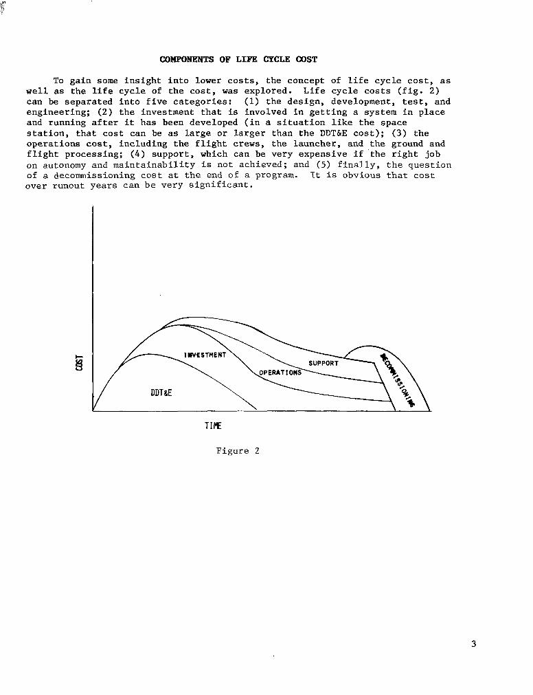
To gain some insight into lower costs, the concept of life cycle cost, as well as the life cycle of the cost, was explored. Life cycle costs (fig. 2) can be separated into five categories: (1) the design, development, test, and engineering; (2) the investment that is involved in getting a system in place and running after it has been developed (in a situation like the space station, that cost can be as large or larger than the DDTdE cost); (3) the operations cost, including the flight crews, the launcher, and the ground and flight processing; ( 4 ) support, which can be very expensive if 'the right job on autonomy and maintainability is not achieved; and (5) finally, the question of a decommissioning cost at the end of a program. It is obvious that cost Over runout years can be very significant.
TIME
Figure 2
3

BARE-BONES PROGRAM
An example s c e n a r i o of the cos t breakdown of a bare-bones program i s shown i n f i g u r e 3 . Hardware cos ts dominate dur ing the ear ly s tages and d isappear dur ing the f l igh t phase . The ope ra t ions cos t becomes the major f ac to r du r ing t he f l i gh t ope ra t ions phase of the program. The control of these runout cos t s w i l l have a very s t rong in f luence on w h e t h e r , i n f a c t , t h e space s t a t ion p rov ides a n e t b e n e f i t .
Figure 3
4
"WHAT IS SYST"S/OPERATIONS TECE.NOLO(;Y?"
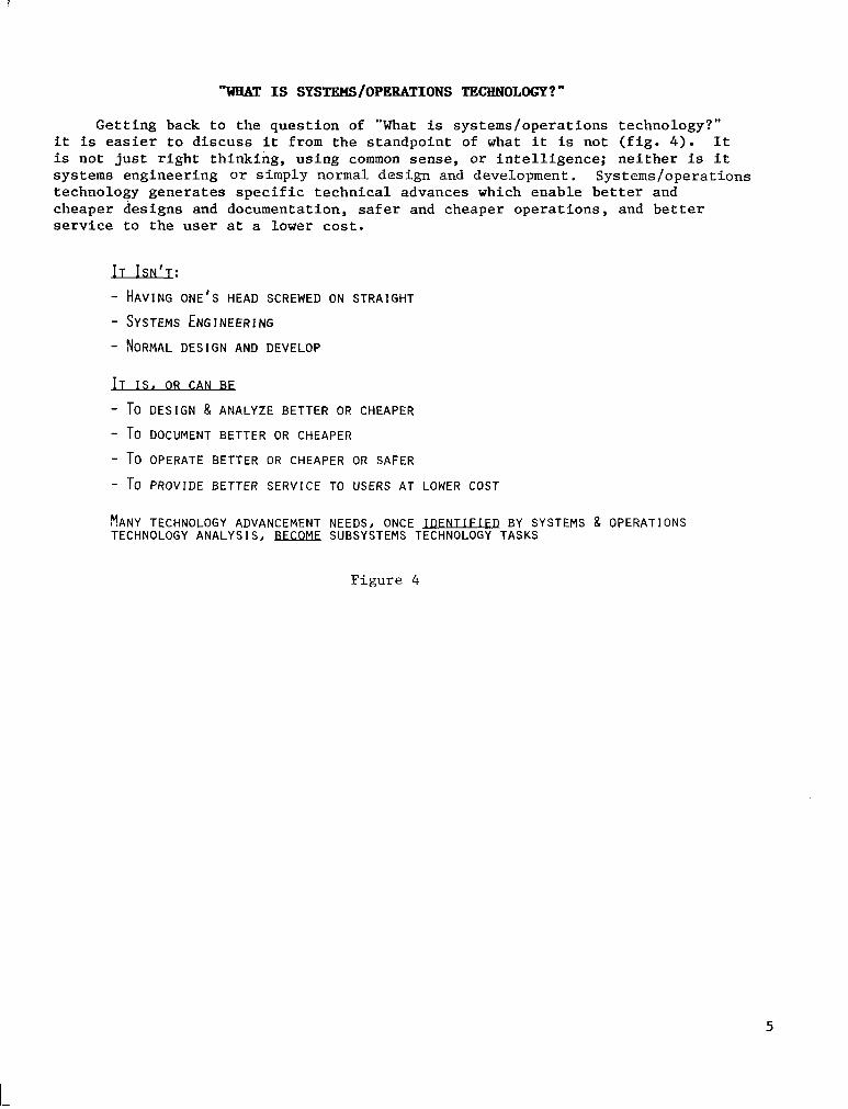
Getting back to the question of "What is systems/operations technology?" it is easier to discuss it from the standpoint of what it is not (fig. 4 ) . It is not just right thinking, using common sense, or intelligence; neither is it systems engineering or simply normal design and development. Systems/operations technology generates specific technical advances which enable better and cheaper designs and documentation, safer and cheaper operations, and better service to the user at a lower cost.
I T ISN'T: - HAVING ONE'S HEAD SCREWED ON STRAIGHT
- SYSTEMS ENGINEERING - NORMAL DESIGN AND DEVELOP
u - TO DESIGN 8 ANALYZE BETTER OR CHEAPER
- TO DOCUMENT BETTER OR CHEAPER
- T O OPERATE BETTER OR CHEAPER OR SAFER
- TO PROVIDE BETTER SERVICE TO USERS AT LOWER COST
YANY TECHNOLOGY ADVANCEMENT NEEDS, ONCE JDFNTI FI ED BY SYSTEMS 8 OPERATIONS TECHNOLOGY ANALYSIS, BBK.QM€ SUBSYSTEMS TECHNOLOGY TASKS
Figure 4
5

SYSTEPZS/OPEBBTLONS TECENOLOGY WORKING GROUPS
Many of the technologies that were identified in the panel sessions, once they were identified, fell into the purview of some other technology panel. Actually, they fall into the category of a subsystem technology. Many of these technologies have been discussed before and were struggled with in earlier NASA meetings. In laying out a framework or agenda for the Systems/ Operations Technology Panel (fig. 5), five working groups were formed. The output of these five working groups constitutes the balance of the panel report.
However, before addressing the output of the working groups, the subject of mission and technology relationship (architecture) was identified. The panel concluded that there is a very important broad overview item that needs to be addressed to deal with, understand, prioritize, and constructively guide the mission and technology relationships. Technology decisions cannot be made in a vacuum. Decisions relative to power may influence decisions relative to propulsion, which may, in turn, influence environmental and life support decisions, which may influence decisions on human capabilities, and so on. This is one of those situations in which almost everything influences every- thing else, and is being referred t o as architecture.
SPACE AND GROUND ASSEMBLY, TEST, CHECKOUT, MAINTENANCE AND SAFETY
L
SYSTEFS ANALYSIS , S IMULATION AND MODELING
T E C H N O L O G I C A L GROWTH
S E R V I C I N G A N D O N - O R B I T O P E R A T I O N S
AlJTOMATION AND AUTONOMY
M I S S I O N AND TECHNOLOGY INTERRELATIONSHIPS (ARCHITECTURE)
F i g u r e 5
6

SPACE AND GBOUND ASSEMBLY AND TEST SUBPANEL
The critique of the Space and Ground Assembly and Test Subpanel (fig. 6 ) pointed out that although life cycle cost is important, it is not enough by itself. Clearly, the least costly life cycle program is the one that is not done. Life cycle cost has to be in the framework of providing a service to the user community.
There is concern over practical aspects of operational flow through a launch site. When discussing distributive architecture in a space station, all of the subsystems are found to be distributed. Hence, there will never be an event or place where you can test just the data management system, just the environmental control and life support system, or just the electrical power system. The only time to determine if these subsystems work is after the system has been assembled in space. It becomes necessary, therefore, to develop the capability of using sophisticated interface simulators and emula- tors to verify that each individual module of the space station is, in fact, functioning properly and interfacing with its partner modules in space.
The planning that was presented at the beginning of the workshop showed a deferral of some tasks affecting maintainability and reliability. It appears that deferral of these tasks was proposed because the tasks were not that well defined. The subpanel suggested that it was important to get the tasks defined and work initiated or the results would occur too late to do any good.
The maintenance objectives that were stated were a little nebulous. Specific quantified numerical objectives, in terms of remove-replace hours and mean time to repair, need to be defined.
FIGURE OF MFRIT
LIFE CYCLE COST BY ITSFI F IS INADEQUATE
SYSTEMS ARCHITECTURF
SUBSYSTEMS THEMSELVES ARE DISTRIBUTED - CAN'T TEST COMPLETE SUBSYSTEM IN ONE MODULE
TASK PHASING
DON'T DEFER M A I N T A I N A B I L I T Y , R E L I A B I L I T Y , SAFETY, RESULTS TOO LATE
MAINTFNANCF
OBJECTIVES THAT WERE STATED ARE TOO NEBULOUS, NEED SPECIFIC OBJECTIVES
Figure 6
7

Recommended tasks in the systems/operations technology area are listed in figure 7 . It is expected that some themes will be recurrent from the other subpanels. One task that should be highlighted is the area of computer-aided engineering, which is an extension of computer-aided design. This ranges from schemes for networking to some fairly ambitious ideas for actually applying artificial intelligence to computer-aided engineering.
IDENTIFICATION AND ASSESSMENT OF MAINTAINABIL ITY AND R E L I A B I L I T Y CONSIDERATIONS RELATIVE TO CANDIDATE SUBSYSTEM TECHNOLOGY OPTIONS,
MANUFACTURING TECHNOLOGY CONSIDERATIONS RELATIVE TO CONCEPTUAL D E F I N I T I O N S ,
IDENTIFICATION OF TECHNOLOGY NEEDED TO IMPLEMENT A COMPUTERIZED ENGINEERING
MODEL,
DEVELOPMENT OF TECHNIQUES TO ENABLE SPECIFICATION OF FORM, F I T AND FUNCTION CONSISTENT WITH THE CONCEPTS OF TECHNOLOGICAL TRANSPARENCY, COMMONALITY AND INTERCHANGEABILITY,
DEVELOP TECHNOLOGY FOR FUNCTIONALLY EQUIVALENT, USER FRIENDLY MISSION SPECIALISTS WORK STATIONS FOR GROUND AND ON-BOARD LOCATION.
DEVELOPMENT OF TECHNOLOGY TO ENABLE INTERCONNECTION OF INDIVIDUAL F IBER OPTIC BUSES AND ON-ORBIT REPAIR OF FIBER OPTIC CABLE,
DETERMINATION OF EFFECTS OF LONG TERM SPACE EXPOSURE ON INTERFACES, SUCH AS THOSE ASSOCIATED WITH PmCm BOARDS AND F L U I D OR ELECTRICAL DISCONNECTS,
Figure 7
8

INDUSTRY COOBDINATION
The panel felt that NASA had been missing the opportunity to benefit the space station program through industry cooperation and recommended continued NASA-industry coordination and cooperation, as outlined in figure 8.
OBSERVATION: U N T I L THE WILLIAMSBURG WORKSHOP, NASA HAS BEEN MISSING THE OPPORTUNITY TO BENEFIT THE SPACE STATION PROGRAM THROUGH INDUSTRY COOPERATION,
RECOMMENDATION:SET UP MECHANISM FOR CONTINUING NASA/INDUSTRY COORDINATION STARTED T H I S WEEK. AS A MINIMUM:
A, TRANSMIT UPDATED TECHNOLOGY PROGRAM PLANNING INFORMATION AND STATUS TO INDUSTRY DISTRIBUTION ON A REGULAR BASIS, INDUSTRY PROVIDE FEEDBACK AND RECOMMENDATIONS,
B , WORK THROUGH 1RP.D PROGRAM TO INFORM INDUSTRY OF SS TECHNOLOGY NEEDS,
C , S T I L L NEED PERIODIC FACE-TO-FACE MEETINGS,
D, NEED TO CONSIDER INCLUDING USERS I N THE TECHNOLOGY COORDINATION A C T I V I T Y #
F i g u r e 8
9
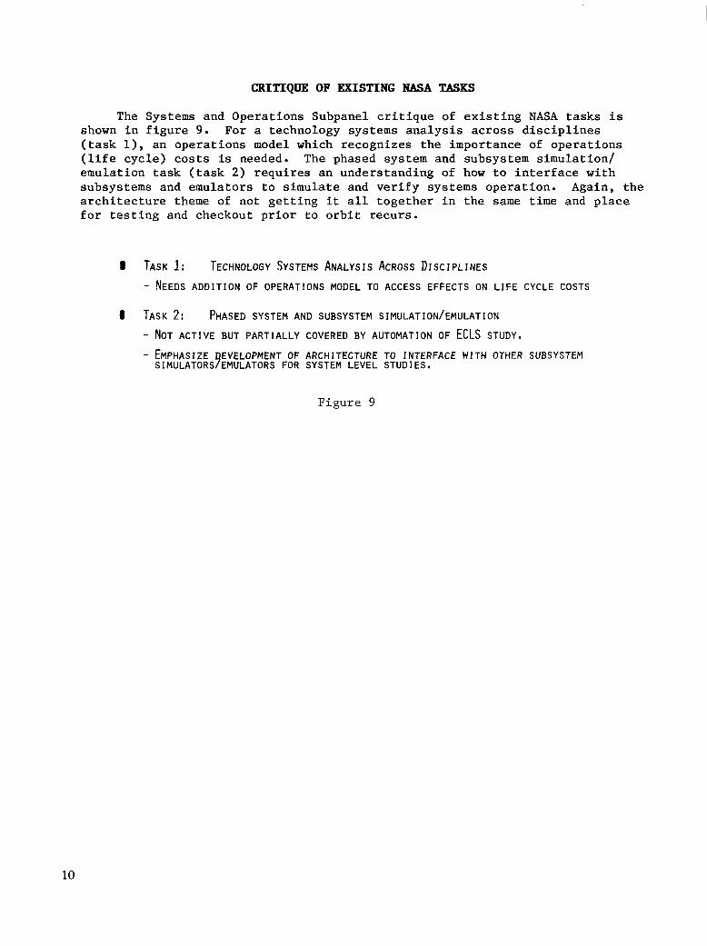
CRITIQUE OF EXISTING NASA TBSKS
The Systems and Operations Subpanel critique of existing NASA tasks is shown in figure 9. For a technology systems analysis across disciplines (task l), an operations model which recognizes the importance of operations (life cycle) costs is needed. The phased system and subsystem simulation/ emulation task (task 2) requires an understanding of how to interface with subsystems and emulators to simulate and verify systems operation. Again, the architecture theme of not getting it all together in the same time and place for testing and checkout prior to orbit recurs.
8 TASK 1: TECHNOLOGY SYSTEMS ANALYSIS ACROSS DISCIPLINES - NEEDS ADDITION OF OPERATIONS MODEL TO ACCESS EFFECTS ON LIFE CYCLE COSTS
TASK 2: PHASED SYSTEM AND SUBSYSTEM SIMULATION/EMULATION
- NOT ACTIVE BUT PARTIALLY COVERED BY AUTOMATION OF ECLS STUDY, - EMPHASIZE EVELOPMENT OF ARCHITECTURE TO INTERFACE WITH OTHER SUBSYSTEM
s IMULATORS7EMULATORS FOR SYSTEM LEVEL STUD1 Es,
Figure 9
10

I'
CRITIQUE OF EXISTING NASA PROGBAH
In critiquing the program in general (fig. lo), the recurring theme of needing plans and architecture to tie together test beds and real-time man-in- the-loop simulations was presented. A scenario dealing with an operation involving the simultaneous simulation of Shuttle flight operations, teleoper- ator maneuvering system operations, EVA operations, and space station IVA operations was discussed. All of these operations may be taking place at different places and different times, and it is necessary to tie them together to get a true mission simulation.
Finally, the engineering data base must be improved by establishing an Agency-wide computer-aided engineering system, incorporating architecture, user interfaces, and user requirements.
0 NEEDS PLAN & ARCHITECTURE TO TIE TOGETHER SUBSYSTEM TEST BEDS TO- INVESTIGATE PERFORMANCE, AUTOMATION TECHNIQUES 8 TO VALIDATE SIMULATORS
0 NEEDS PLAN X ARCHITECTURE TO TIE TOGETHER REAL TIME MAN-IN-LOOP SI~ULATORS
0 DEVELOP SYSTEM SIMULATORS THAT UTILIZE TEST BEDS/SIMULATORS
AGENCY WIDE COMPUTER AIDED ENGINEERING SYSTEM, DEFINE: IMPROVE ENGINEERING DATA BASE AS PROGRAM. EVOLVES BY ESTABLISHING AN
- ARCHITECTURE - USER INTERFACES - USER REQUIREMENTS
F i g u r e 10
11

The recommended tasks from the Systems Analysis, Simulation, and Modeling Subpanel are l€sted in figure 11. Again, a thorough job of integrating the results of the various subpanels needs to be done to eliminate overlap. Although a few recurring situations exist, the following major themes come out strong: (1) computer-aided engineering, (2) simulation, ( 3 ) emulation, (4) understanding how to deal with a truly distributive system that is incrementally bu€lt in space, and (5) new technology, new ways of doing business.
ARCH I TECTURE :
8 ORGANIZE TOP LEVEL WORKING GROUP TO CONTROL ARCHITECTURE 8 GROWTH OF SIMULATORS 8 COMPUTER-AIDED SYSTEMS
8 SYSTEMS ARCHITECTURE TO TIE TOGETHER MAN-IN-LOOP SIMULATORS
0 SYSTEMS ARCHITECTURE TO TIE TOGETHER SUBSYSTEM TEST BEDS
0 DEVELOP PROGRAM WIDE COMPUTER AIDED ENGINEERING TOOL
SI MULATORS :
@ STRUCTURE AN APPROACH TO VERIFY AND CLASSIFY EXISTING SIMULATORS
I DEVELOP HIGH FIDELITY GRAPHICS SIMULATORS TO REDUCE NEED FOR MOCK-UPS
0 DEVELOP HIGH SPEED USER FRIENDLY PARALLEL PROCESSORS AS A SIMULATOR TOOL
8 DEVELOP TECHNIQUES TO VERIFY DYNAMIC SIMULATORS USED FOR MAN-IN-LOOP BERTHING,
DATA BASE:
DOCKING AND CONTROL EVALUATIONS
DEVELOP EVOLVING DATA BASE THAT USES ADVANCED S/W TOOLS
F i g u r e 11
12
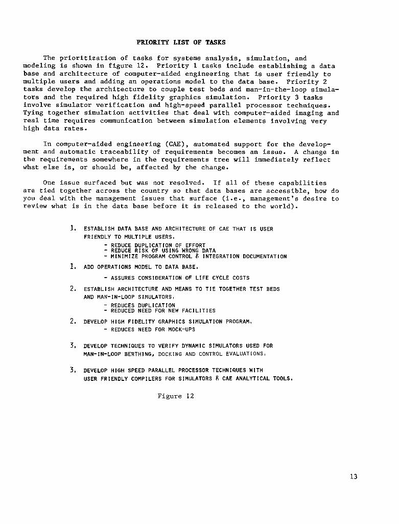
PRIORITY LIST OF TASKS
The prioritization of tasks for systems analysis, simulation, and modeling is shown in figure 12. Priority 1 tasks include establishing a data base and architecture of computer-aided engineering that is user friendly to multiple users and adding an operations model to the data base. Priority 2 tasks develop the architecture to couple test beds and man-in-the-loop simula- tors and the required high fidelity graphics simulation. Priority 3 tasks involve simulator verification and high-speed parallel processor techniques. Tying together simulation activities that deal with computer-aided imaging and real time requires communication between simulation elements involving very high data rates.
In computer-aided engineering (CAE), automated support for the develop- ment and automatic traceability of requirements becomes an issue. A change in the requirements somewhere in the requirements tree will immediately reflect what else is, or should be, affected by the change.
One issue surfaced but was not resolved. If all of these capabilities are tied together across the country so that data bases are accessible, how do you deal with the management issues that surface (i.e., management's desire to review what is in the data base before it is released to the world).
1, ESTABLISH DATA BASE AND ARCHITECTURE OF CAE THAT I S USER FRIENDLY TO MULTIPLE USERS,
- REDUCE DUPLICATION OF EFFORT - REDUCE R I S K OF USING WRONG DATA - M I N I M I Z E PROGRAM CONTROL c?, INTEGRATION DOCUMENTATION
1, ADD OPERATIONS MODEL TO DATA BASE,
- ASSURES CONSIDERATION OF L I F E CYCLE COSTS
2. ESTABLISH ARCHITECTURE AND MEANS TO T I E TOGETHER TEST BEDS AND MAN-IN-LOOP SIMULATORSm
- REDUCES DUPLICATION - REDUCED NEED FOR NEW F A C I L I T I E S
2, DEVELOP H I G H F I D E L I T Y GRAPHICS SIMULATION PROGRAM, - REDUCES NEED FOR MOCK-UPS
3, DEVELOP TECHNIQUES TO VERIFY DYNAMIC SIMULATORS USED FOR MAN-IN-LOOP BERTHING, DOCKING AND CONTROL EVALUATIONS,
3, DEVELOP HIGH SPEED PARALLEL PROCESSOR TECHNIQUES WITH USER FRIENDLY COMPILERS FOR SIMULATORS pt CAE ANALYTICAL TOOLS,
Figure 12
13

In the subpanel meetings on technology growth, a number of interesting issues were addressed. Some major and/or prevalent views on technology growth are listed in figure 13.
- GENERAL AGREEMENT ON KEY QUESTION/SESSION OBJECTIVE AND TYPICAL ISSUES
- SOME MAJOR/PREVALENT THOUGHTS - LACK OF KNOWLEDGE OF FUTURISTIC REQUIREMENTS DOESN'T ALLOW MUCH
"PROVIDING" I N THE I N I T I A L STATION - EVEN WITHOUT REQUIREMENTS - U T I L I T I E S SHOULD BE DESIGNED FOR SONE TECHNICAL
GROWTH CAPABILITY (INTELLIGENT OVERKILL) - SUEJECTIVE JUDGMENT LEANING TOWARD MODULE RETURNS TO GROUND
FOR REFURBISHMENT AS MECHANISM FOR TECHNOLOGY GROWTH (TRADE STUDY MUST €VALUATE)
- PAYLOADS/SPACE STATION SYSTEM/SUBSYSTEM MUST BE DESIGNED TO ACCEPT REFURB I SMENT
F i g u r e 13
14
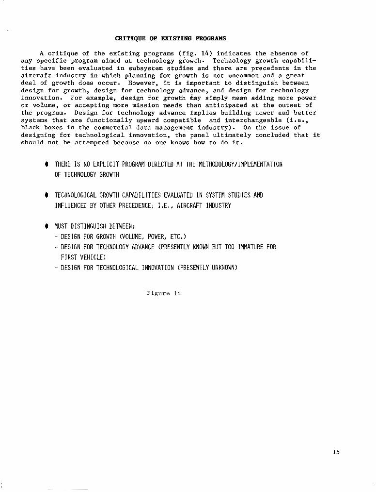
CRITIQUE OF EXISTING PBOGBBMS
A critique of the existing programs (fig. 14) indicates the absence of any specific program aimed at technology growth. Technology growth capabili- ties have been evaluated in subsystem studies and there are precedents in the aircraft industry in which planning for growth is not uncommon and a great deal of growth does occur. However, it is important to distinguish between design for growth, design for technology advance, and design for technology innovation. For example, design for growth may simply mean adding more power or volume, or accepting more mission needs than anticipated at the outset of the program. Design for technology advance implies building newer and better systems that are functionally upward compatible and interchangeable (i.e., black boxes in the commercial data management industry). On the issue of designing for technological innovation, the panel ultimately concluded that it should not be attempted because no one knows how to do it.
0 THERE I S NO EXPLICIT PROGRAM DIRECTED AT THE METHODOLOGY/IMPLEMENTATION OF TECHNOLOGY GROWTH
0 TECHNOLOGICAL GROWTH CAPABILITIES EVALUATED I N SYSTEM STUDIES AND INFLUENCED BY OTHER PRECEDENCE; I , E , J AIRCRAFT INDUSTRY
0 MUST DISTINGUISH BETWEEN: - DESIGN FOR GROWTH (VOLUME, POWER, ETC, 1 - DESIGN FOR TECHNOLOGY ADVARCE (PRESENTLY KNOWN BUT TOO IMMATURE FOR
FIRST VEHICLE) - DESIGN FOR TECHNOLOGICAL INNOVATION (PRESENTLY UNKNOWN)
Figure 14
15

KEY QUESTION AND TPPICAL ISSUES
The key question in technology growth is how the emerging technologies are recognized and incorporated into the initial program with minimal impact, especially since incorporation does not come free. Some typical issues are listed in figure 15. Do subsystems evolve or grow by replication, or are they replaced? The answer is probably "yes" to all of these. Do technology improvements save dollars, improve system capability, and provide better user service? What is the funding level, the front-end costs, required to build in the capability for growth? Frequently, programs are initiated with good intentions to provide for growth and technology advancement, but the bottom line is cost. Some item in the program must be traded out in order to include the cost of technology advancement, and that becomes a difficult management decision.
KEY QUESTION
0 FOR A LONG-TERM SPACE STATION PROGRAM, HOW ARE EMERG IN6 TECHNOLOGIES RECOGNIZED AND INCORPORATED INTO THE PROGRAM WITH MINIMUM IMPACT?
SOME TYPICAL ISSUES
0 ARE SYSTEMS/SUBSYSTEMS EVOLVED, REPLICATED, REPLACD? 0 ARE PROPOSED TECHNOLOGY IMPROVEMENTS PROJECTED TO SAVE DOLLARS,
SATISFY REQUIREMENTS, BOTH? 0 HOW TO ESTABLISH LONG-TERM REQUIREMENTS, MESH WITH TECHNOLOGY LEAD
TIMES AND ESTABLISH APPROPRIATE FUNDING? 0 CAN HIGHER PROGRAM FRONT-END COSTS BE TOLERATED TO BUILD I N CAPABILITY
FOR TECHNOLOGY GROWTH?
Figure 15
16

TECHNOLOGY GROWTH OR STAGNATION
One issue that is always faced when dealing with new technology is that of technology advancement versus technology stagnation (fig. 16). The world of technologists works diligently toward technology advancement. In the program management situation, there is always the risk-avoidance motivation which tends to say "Use what's tried and true." When weighing the benefits of technology advancement, a percentage of the technology items will have had applicability beyond the immediate program, and this must be considered. Many technology areas, like data management initiatives and integrated hydrogen- oxygen systems, do not apply just to space stations. They apply to everything that is done in space.
So the key issue in technology growth is how to target growth and how to make it happen. This goes beyond just technology.
o RISK AVOIDANCE MOTIVATES STAYING WITH "TRIED AND TRUE"
0 T E C H N O L O G Y A D V A N C E M E N T H A S B R O A D A P P L I C A B I L I T Y
o HOW DO WE TARGET GROWTH AND MAKE IT HAPPEN?
F i g u r e 16
17

The space station will require operational, integrational, and develop- mental "system goals" that will dictate architectural-cultural changes, since it is a different kind of system than any previously developed (fig. 17). Operationally, the space station will be reconfigured in orbit and the crew will assume a systems manager's role instead of simply an operator's role. Progressive automation will ensure flexible man/i;lachine roles. Integration goals include procurement flexibility (particularly for high-cost items) and user-friendly and progressive checkout. Again, because the total system cannot be assembled and tested until it is in space, there is a requirement for smart assemblies.
(OPERATIONAL: I 0 IN ORBIT RECONFIGURATION. . . lncreased Facility Capability dr User Demands
0 BROAD CREW MODEL.. . Systems Manager Nor Operator
0 TECHNOLOGY TRANSPARENCY.. . Planned incremental Upgrades
0 FLEXIBLE MANMACHINE ROLES. . . Progressive Automation
I INTEGRATION: I 0 PROCUREMENT FLEXIBILITY.. . Separate Modules & GFE for High $ items
0 USER FRIENDLY. . . Reduce lntegratlon Cycle Time dr Complexlty
0 STREAMLINED HW/SW VERIFICATION.. . Decrease Facllity dr Time Req'd
0 PROGRESSIVE CHECKOUT. . . More Sell Off et Yendor, Less et integrator
1 DEVELOPMENT:
0 SMART ASSEMBLIES . . . Local Control dr Standarrflnterface
F i g u r e 1 7
18
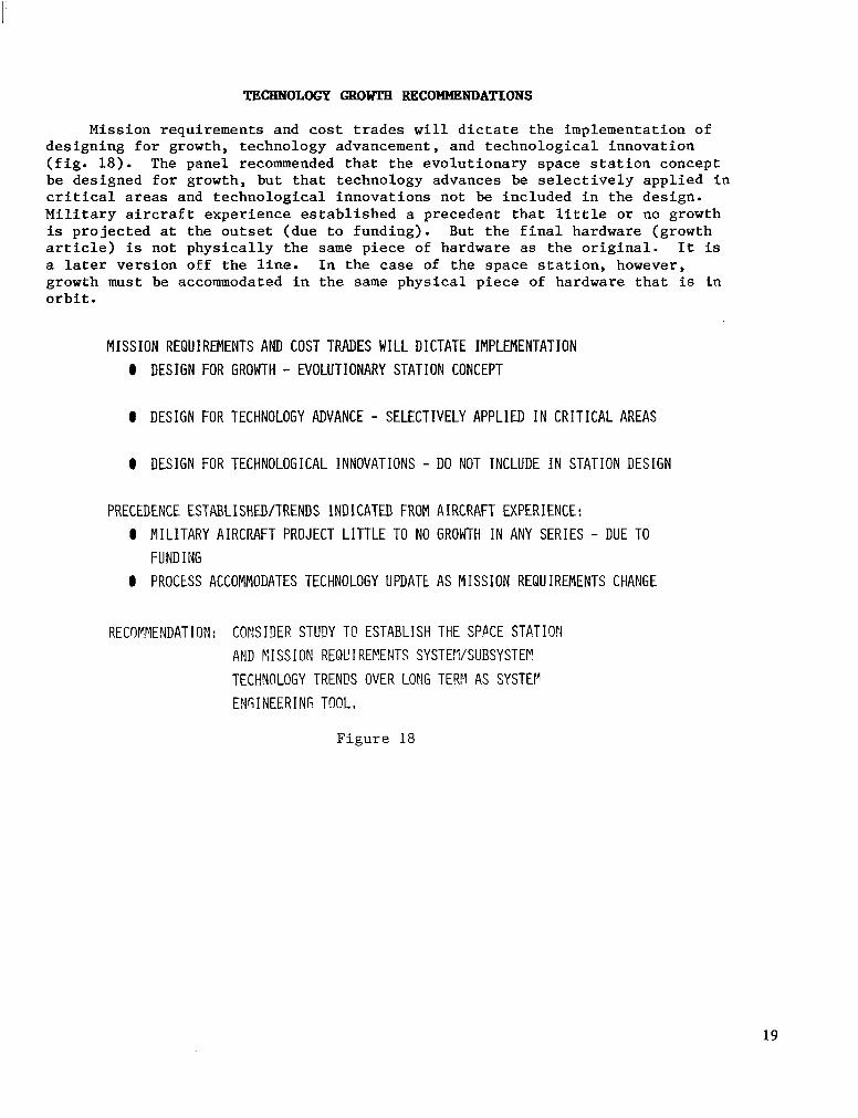
TECHNOLOGY GROWTH RECOMMENDATIONS
Mission requirements and cost trades will dictate the implementation of designing for growth, technology advancement, and technological innovation (fig. 18). The panel recommended that the evolutionary space station concept be designed for growth, but that technology advances be selectively applied in critical areas and technological innovations not be included in the design. Military aircraft experience established a precedent that little or no growth is projected at the outset (due to funding). But the final hardware (growth article) is not physically the same piece of hardware as the original. It is a later version off the line. In the case of the space station, however, growth must be accommodated in the same physical piece of hardware that is in orbit.
MISSION REQUIREMENTS AND COST TRADES WILL DICTATE IMPLEMENTATION 0 DESIGN FOR GROWTH - EVOLUTIONARY STATION CONCEPT
0 DESIGN FOR TECHNOLOGY ADVANCE - SELECTIVELY APPLIED I N C R I T I C A L AREAS
0 DESIGN FOR TECHNOLOGICAL INNOVATIONS - DO NOT INCLUDE I N STATION DESIGN
PRECEDENCE ESTABLISHUI/TRENDS INDICATUI FROM AIRCRAFT EXPERIENCE: 0 MILITARY AIRCRAFT PROJECT LITTLE TO NO GROWTH I N ANY SERIES - DUE TO
FUND I iJG 0 PROCLSS ACCOMMODATES TECHNOLOGY UPDATE AS MISSION REQUIREMENTS CHANGE
RECOP!I.lENDATIOPI: COHSIIIEP. STUDY TC! ESTABLISH THE SPPCE STATIOY AND N I ss I or! REQU I REFENTS SYSTEVSUBSYSTEP TECHMLOGY TRENFS OVER LONG TERR AS SYSTEV ENGINEERING TOOL,
F i g u r e 18
19
SERVICE AND ("ORBIT OPERATIONS CRITIQUE
The Service and On-Orbit Operations Subpanel reported the need to accel- erate and increase the scope of the contamination task (fig. 19). Contamina- tion is an important, user-critical, and multi-faceted issue with many kinds of problems. In addition to natural environment and induced environment contamination, there are many sources of contamination and effects that are not understood. The subpanel also recommended that spacecraft charging and plume impingement be added to the task, to attack the whole task as an integrated activity. Fluid and cryogenic transfer and cryogenic management tasks should be accelerated. The issue of zero-gravity transfer is very important and work needs to be accelerated. It is necessary that the impacts and where they fall be understood before real hardware is designed. On-orbit deployment and spacecraft final checkout need to be added, and the formation flying task should be deleted, since it is already understood (formation flying is flight mechanics, not technology).
0 A C C E L E R A T E A N D I N C R E A S E S C O P E O F C O N T A M I N A T I O N T A S K
- M O S T I M P O R T A N T
- F O L D I N C H A R G I N G A N D P L U M E I M P I N G E M E N T
0 A C C E L E R A T E F L U I D S A N D C R Y O G E N I C S T R A N S F E R
0 A D D O N - O R B I T D E P L O Y M E N T S A N D F I N A L C H E C K O U T O F S P A C E C R A F T
0 D E L E T E F O R M A T I O N F L Y I N G
- A L R E A D Y U N D E R S T O O D - N O T T E C H N O L O G Y
Figure 19
20
SERVICING AND ON-ORBIT OPERATIONS PRIORITIES
The prioritization of tasks in servicing and on-orbit operations is listed in figure 20. Contamination is the most critical. On-orbit servicing, including both spacecraft servicing and servicing via propellant transfer, is second. The assessment of a logistics support vehicle and the orbital atmospheric-environment dynamics (which relates to contamination) complete the priority listing.
P R I O R I T I E S
1, 2, 3 , 4,
CONTAMINATION PREDICTION AND PROTECTION ON-ORB I T SERV I c I NG
SPACE STATION LOGISTICS SUPPORT VEHICLE ASSESSMENT
ORBITAL ATMOSPHERIC-ENVIRONMENT DYNAEICS
Figure 20
2 1

The Automation/Autonomy Subpanel recommended five areas for technology advancement (fig. 21). The first area involved the application of artificial intelligence and expert systems to spacecraft services and self management. Current artificial intelligence research emphasizes the development of’self- modifying codes; that is, software that learns,,modifies itself, and becomes smarter and better. Useful results are being obtained in this area and some expert systems have been built which do reasonably well. Some exploratory work is being conducted at NASA Kennedy Space Center on the application of expert systems to ground support operation (ground support automation). The real benefit of expert systems is to reduce the number of human experts needed to do a given job that requires human expert judgment. The human experts cannot be eliminated, but they can be made more productive. This is the recurring theme for development of automated design and analysis tools. [It is the personal view of the presenter that there is potentially a very large cost impact (cost savings) in this area, primarily because it is not under- stood and no one knows how to plan for it.] Since cost estimates tend, to some extent, to be self-fulfilling prophecies, it is important to understand the potential of this automated technology before the space station program costs are cast in concrete and budgeted. Robotics on the space station will be used for inspection, assembly, servicing, and repair. Here, robotics deals with true robotics (machine intelligence is applied and the robot is autonomous) and telepresence. (Communication techniques put man in the loop remotely in such an intimate fashion that he loses contact with where he really is and he feels that he is there and doing what his telepresence robot is doing.) Also, there is a need for technology advancement in automation t o support simulation, evaluation, and training laboratories.
I I SPACECRAFT SERVICES SELF-PAMAGEMENT -- A , I
2 I C;ROI!?ID SUPPORT AUTOFATlOY
3 , SP4CE ST!.TION POBOTICS FoR INSPECTInNJ A.SSEYBLYJ SEP,VICI!4G AND REPAIF., REFU9EISHFENT 4NT! “IN-ORBIT EXPER I YENT I MTERACT I OW I
Q m PHYSICAL SIP!ULATIO!lJ EVALUATION, ANLI TR4INING LABORATORIES,
Figure 21
22

INDUSTRY COORDINATION
The Automation/Autonomy Subpanel observed that the NASA Office of Aeronautics and Space Technology has demonstrated a serious interest in automation technology and has had some impact on the evolution of automation technology, but current funding levels are inadequate (fig. 22). It was recommended that a Systems and Operations Working Group Subcommittee for Automation be established and that funding for advanced automation technology be increased.
OBSERVATIONS : NASA OAST HAS DEMONSTRATED A SERIOUS INTEREST I N AUTOMATION TECHNOLOGY. NASA HAS HAD SOME IMPACT ON THE EVOLUTION OF AUTOMATION TECHNOLOGY . CURRENT FUNDING LEVELS ARE INADEQUATE .
RECOMMENDATIONS: ESTABLISH A SYSTEMS AND OPERATIONS WORKING GROUP SUBCOMMITTEE FOR AUTOMATION . INCREASE FUNDING FOR ADVANCED AUTOMATION TECHNOLOGY .
F i g u r e 2 2
23
ISSUES FOB BgSEARCEI
The Systems and Operations Technology Panel concluded the working session with five issues for research (fig. 23) . Understanding the issue of mission and technology relationships (the relationship of the technological architec- ture to the system operational architecture) will stimulate knowledge of how the technologies will interplay and how to priorjtize the technologies across the board, make advances, incorporate the advances into the system, and realize the potential benefits.
In automation and autonomy, the issue is how, when, where, why, at what cost, and to what benefit are new concepts such as artificial intelligence, expert systems, and natural language packages going to be used. Will they be used in space, on the ground, in the design process, or across the board?
Key issues include (1) greater reliance on computer generated imagery and software data management types of simulations rather than on real physical simulation, (2 ) the ability to tie the flight and ground systems together to do integrated simulations of checkout procedures, and ( 3 ) emphasis on mainte- nance and repair activities. Engineering data base and standards issues include, for example, the real standards that should be applied to a space station for crew safety.
The computer-aided engineering systems analysis tools provide the possi- bility of tying everything together into some form of integrated network to take maximum advantage of benefits. This does not mean that human innovation and judgment will be replaced. Instead, the routine work that goes into the engineering and development process will be eliminated.
MISSION AHD TECHNOLOGY INTERRELATIONSHIPS ("ARCHITECTURE")
AUTOMATION/AUTONOMY
SIMULATION - EMULATION
ENGINEERING DATABASE/STANDARBS
SYSTEM ANALYSIS TOOLS
F i g u r e 2 3
24
CREW AND LIFE SUPPORT: EVA
Richard S . Johnston Texas Medical Center, Incorporated
Houston, Texas
Space Station Technology Workshop Williamsburg, Virginia
March 28-31, 1983
25

PNA SYSTEMS elwBL
The composit Lon of the EVA Systems Panel is given in figure 1 .
0
0
0
0
0
0
0
0
0
AEROSPACE CORPORATION
LOCKHEED MISSILES AND SPACE COMPANY
GENERAL ELECTR I c COMPANY
MARTIN ~IAR I ETTA AEROSPACE
HAMILTON-STANDARD CORPORATION
LIFE SUPPORT SYSTEMS, INC,
STANFORD RESEARCH INSTITUTE
ILC DOVER
USAF SCHOOL OF AVIATION MEDICINE
Figure 1
26

GENERAL RE-ATIONS ANJI OBSERVATIONS
Four general recommendations by the EVA subpanel are l i s t e d i n f i g u r e 2. There is a s t rong need fo r an EVA des ign s tandard document t o be developed i n the next year and updated as technology progresses. Too many times, ques t ions are answered or problems solved i n one program, but these are not documented and ava i l ab le t o assist another program at a later time. The EVA design people need to develop a c l o s e r r e l a t i o n s h i p ( c o u p l i n g ) w i t h t h e u s e r comntu- nity. For example, satell i te and spacecraf t designers need to develop a mutual understanding of the requirements for EVA crewmen as well as of how these requirements can be provided. Another concern was the seeming lack of c e n t r a l i z e d r e s p o n s i b i l i t y w i t h i n NASA f o r EVA a c t i v i t i e s . I n d u s t r y v i s i t s t o d i f fe ren t Centers and even wi th in Centers ind ica ted a l ack of an EVA advocacy o r t o t a l u n d e r s t a n d i n g of EVA problems. The cu r ren t workshop and panel a c t i v i t y was very useful and, if continued, would s e r v e t o promote an exchange of information, and an understanding of user problems and t o s t i m u l a t e t h e technology area.
EVA DESIGN STANDARD DOCUMENT NEEDS TO BE DEVELOPED I N NEXT 6-12 MONTHS AND UPDATED AS TECHNOLOGY PROGRESSES
NASA NEEDS TO COUPLE EVA DESIGN PERSONNEL CLOSER TO USER COMMUN I TY
THERE APPEARS TO BE A LACK OF CENTRALIZED NASA RESPONSIBILITY FOR THE EVA COMMUNITY
PANEL ACTIVITY SHOULD CONTINUE TO PROMOTE EXCHANGE OF INFORMATION AND UNDERSTANDING OF USER PROBLEMS, AND TO STIMULATE TECHNOLOGY A C T I V I T Y
F i g u r e 2
27

EVA SPSTKMS PLAN SUMMARY
A quick summary of t he t echno log ie s t ha t NASA i n t e n d s t o p u r s u e f o r t h e s p a c e s t a t i o n a c t i v i t y i s l i s t e d i n f i g u r e 3. The EVA design and operat ions cri teria are a d e f i n i t i o n of t h e r e q u i r e m e n t s t h a t e x i s t f o r the development o f equ ipmen t , p rocedures , and ope ra t iona l ac t iv i t i e s . Space su i t p l ann ing emphasizes the technology areas and the development of a h i g h e r m o b i l i t y s u i t which would operate a t a h igher p ressure and requi re the des ign of new j o i n t s and gloves. The e x i s t i n g space s u i t s which are u s e d i n t h e S p a c e S h u t t l e o p e r a t e i n a 1-atmosphere environment and require 3-1/2 hours preoxygenation p r io r t o ope ra t ion . Th i s lag time imposes a hardship and a l i m i t a t i o n on r ap id ope ra t iona l suppor t i n go ing i n to EVA. One of t he goa l s i s t o e l i m i n a t e t h a t problem. Some new innovat ive ideas inc lude pass ive thermal p ro tec t ion f o r s p a c e s u i t s . The outer cover ing of the Apollo EVA s u i t s was a super- i n s u l a t i o n c o v e r a l l which provided passive thermal protection. There are l i m i t a t i o n s and problems i n f a b r i c a t i o n a n d d u r a b i l i t y of t h e material but some of the new concepts can greatly improve that . Head-up d i sp lays are being cons ide red t o make the EVA crewman's j o b easier by el iminat ing cue cards and normal aids which are now used. In-fl ight maintenance of space s t a t i o n s u i t s must be b u i l t i n t o t h e t e c h n o l o g y . ( I t is n o t f e a s i b l e t o r e t u r n s p a c e s u i t s t o Hous ton for repa i r . ) The p o r t a b l e l i f e s u p p o r t s y s t e m (PLSS) (or backpack) i s a u n i t which provides O2 and removes CO2 and provides a l i veab le env i ron - ment i n space . Some of t he f ea tu re s be ing cons ide red i n t h i s t echno logy inc lude nonvent ing to p rec lude water vapor from being dumped i n t o t h e c a b i n atmosphere and contaminating sensors or other equipment, and the reduction of expendables such as l i thium-hydroxide cartridges, which are one-use items. Lithium hydroxide is used to absorb carbon dioxide to keep the C02 l e v e l s down. An a l t e r n a t e r e g e n e r a t i v e method of c o l l e c t i n g C02 without the waste of 7 pounds of weight for each EVA i s be ing inves t iga ted . Another aspec t of t he PLSS technology program involves extended duration, in-fl ight maintenance. In the manned maneuvering area, the cu r ren t manned maneuvering unit (MMU) i s l i m i t e d somewhat i n i t s range th rough opera t iona l cons t ra in ts and a lack of operat ional experience. There is a need f o r improved guidance i n t h e d i s p l a y to g ive an ex tended range capabi l i ty wi th in good sens ib l e ope ra t iona l con- s t r a i n t s . A l s o i n t h e p l a n is i n t e g r a t i o n of the display systems and overal l i n t e g r a t i o n of the ex t ra -vehicu lar mobi l i ty un i t (EMU), a combination of the s u i t and backpack. The last item i n NASA's technology task i s t h e EVA area of t o o l s , work s t a t i o n , l i g h t i n g , and o t h e r EVA aids . These are the necessary items when a crewman goes out to perform a cons t ruc t ion t a sk , make repairs, or ca r ry ou t o the r u se fu l func t ions . Ce r t a in of t hese items need t o be developed and i n t e g r a t e d i n t o a system. With the extensive experience avai lable a t t h i s workshop, the panel developed an overview of user requirements from a p rac t i ca l v i ewpo in t .
o EVA DESIGN 2 OPERATIONS CRITERIA
o SPACE SUITS
o PORTABLE L I F E SUPPORT SYSTEMS
o MANriED PA4NEUVERING L N I T
o EVA - SIORK STATIONS, TOOLS, ETC,
Figure 3
28

The p a n e l f e l t t h a t t h e NASA p lan w a s technically sound and took no e x c e p t i o n t o t h e p r i o r i t i e s t h a t were e s t a b l i s h e d ( f i g . 4 ) . The o rde r of p r i o r i t y w a s design cri teria, EMU technology, MMU technology, and EVA t o o l s and work s ta t ions . In f ine- tuning the p rogram conten t , the pane l recommended two items fo r de l e t ion , p r imar i ly because i t had been demonstrated a t t h i s po in t t ha t t hese t echno log ie s were needed. Recommended expansion of the program included plans for a second generation space u n i t , l i g h t i n g , d i s p l a y i n t e g r a t i o n f o r EMU and MMU, and crew EVA aids . The space s ta t ion program is being designed for growth and the EVA and space sui t areas are no d i f f e r e n t than other technology areas. The technology plan that NASA has developed w i l l produce a s u i t f o r t h e f i r s t s p a c e s t a t i o n . However, i t is e a s y t o g e t t r a p p e d i n t o t h e b e l i e f t h a t t h i s i s t h e s u i t and i t w i l l last forever . In p l ann ing fo r a space s t a t i o n t h a t w i l l last f o r a decade, there are i d e a s i n the wings which w i l l g ive g rea t e r f l ex ib i l i t y and pe r fo rmance capab i l i t y , and the long-range plan should consider the next generation suit . Some a d d i t i o n a l sub ta sks were recommended, most of them s t u d i e s . R e l a t i v e t o t h e q u e s t i o n of atmospheric composition i n t h e s p a c e s t a t i o n a n d t h e s u i t , NASA should es tab- l i s h a s p e c i f i c a t i o n f o r e a c h t o s t o p t h e w a s t e d e f f o r t i n i n d u s t r y . A l s o , a n airlock requirements and design study should be i n i t i a t e d . The committee s t r o n g l y f e l t t h a t t h e r e were some unique ideas and multipurposes which an air lock can perform other than the task of moving a person from a normal cabin atmosphere into the vacuum of space.
0 BASIC PLAN - TECHNICALLY SOUND 0 PROGRAM CONTENT - (FINE TUNING)
- DELETION: o EXOSKELETAL FORCE AMPLI F I ER
o END ITEM EFFECTOR - EXPANDED SCOPE:
o PLANNING FOR SECOND GENERATION SPACE SUIT
o LIGHTING o INTEGRATE Ei:lU/MMU D I SPLAYS
o CREW EVA AIDS - ADD IT I ONAL SUBTASKS :
o SPACE SUIT MATERIAL COMPATABILITY STUDY o RADIATION ENVIRONMENT/PROTECTION STUDY
o SS/SPACE SUIT ATMOSPHERE o AIRLOCK REQUIREMENTS 8 DESIGN STUDY
Figure 4
29
I
The technology plan, as presented, was r e s t r i c t e d t o t h e s p a c e s t a t i o n . Consequently, i t d id no t relate to today ' s p roblems, to the f low of develop- ment which has gone i n t o t h e S h u t t l e program and t o t h e e x p e r i e n c e s t h a t w i l l a cc rue as t h e S h u t t l e is operated ( f ig . 5 ) . The p l a n f o r s p a c e s t a t i o n t e c h - nology i s not inadequate, but i t needs a la rge range , more de t a i l ed p l an . More emphasis should be placed on the oppor tuni ty to deve lop and eva lua te EVA technology in the Space Shut t le missions. To b u i l d a n a r s e n a l of technology t o move to the space s ta t ion p rogram, there w i l l be many EVA o p p o r t u n i t i e s on Shu t t l e f l i gh t s wh ich , on a noninterference basis , could be u s e d t o e v a l u a t e new t o o l s , m o b i l i t y a i d s , r e s t r a i n t s , and l i g h t i n g . In t h i s way, a f t e r 6 o r 7 yea r s of o p e r a t i o n a l f l y i n g i n t h e S h u t t l e , many problems that can only be worked on in the space environment w i l l be solved.
o NASA EVA SYSTEMS TECHNOLOGY PLAN DID NOT INCLUDE
NEAR TERM (SPACE SHUTTLE) TECHNOLOGY IMPLEMENTATION ACTIVITY, NOTE: INADQUATE TIME TO TRULY UNDERSTAND
D E T A I L S OF P L A N ,
o MORE EMPHASI s SHOULD BE GIVEN TO THE OPPORTUNITY
TO DEVELOP AND EVALUATE EVA TECHNOLOGY IN SPACE SHUTTLE HISSIONS,
F i g u r e 5
30

BECCMMKNDATIONS ON SCHEDULES
Peop le i n t he i ndus t ry f ee l t ha t t he s chedu les cou ld and shou ld be accel- e r a t e d ( f i g . 6 ) . Specif ical ly , developmental work on the non-prebreathe rap id-don opera t iona l space su i t (PSI su i t ) should be a c c e l e r a t e d . The PSI s u i t i s needed f o r t h e s p a c e s t a t i o n a n d , i n time, w i l l be needed for the Shu t t l e . PSI su i t t echnology i s i n e x c e l l e n t s h a p e . In f a c t , a prototype of a PSI s u i t i s s c h e d u l e d f o r d e l i v e r y t o NASA next month. R e a l i s t i c a l l y though, the PSI sui t i s probably 2 years f rom being f l ight equipment . Also, work in t he sys t em des ign c r i t e r i a / s t anda rds shou ld be accelerated. There is a real need i n t h e u s e r community t o t r u l y u n d e r s t a n d t h e c u r r e n t c a p a b i l i t i e s f o r a n EVA crewman. The manual should be maintained up t o d a t e t o s e r v e as a dynamic design/standards manual and be a v a i l a b l e t o t h e u s e r community ( u s e r f r i e n d l y ) .
o TECHNOLOGY SCHEDULES CAN AND SHOULD BE ACCELERATED:
- RAPID DON/OPERATION SPACE SUIT DEVELOPMENT SHOULD BE ACCELERATED -
- NEEDED FOR S P A C E S T A T I O N
- NEEDED FOR SPACE SHUTTLE - TECHNOLOGY IN GOOD SHAPE
2 YEARS FROM FLIGHT EQUIPMENT
o EVA SYSTEMS DESIGN CRITERIA/~TANDARDS SHOULD BE
ACCELERATED
o NEEDED BY SATELLITE DESIGNERS IN SPACE SHUTTLE
Figure 6
31

FUNDING REC(WMENDATI0NS
I n t he area of funding, no one ever wants to say tha t there is enough money i n t h e program ( f i g . 7). Funding for EVA c r i t e r i a and EMU and MMU technology is cons ide red t o be marginal ly adequate . However, EVA support t e c h n o l o g y ( t o o l s , r e s t r a i n t s , work s t a t i o n s ) i s underfunded. There was insu f f i c i en t t ime o r de t a i l s t o conduc t an i n depth cost review.
o PANEL FINDINGS - FUNDING CONSIDERED PIARG INALLY ADEQUATE FOR FOLLOW I NG
TASKS :
o EVA CRITERIA o EMU TECHNOLOGY o MMU TECHNOLOGY
- FUND I NG CONS I DERED INADEQUATE
o EVA SUPPORT TECHNOLOGY (TOOLS, RESTRAINTS, WORK
STAT I ONS 1
NOTE: PANEL D I D NOT HAVE TIME OR SUFFICIENT DETAILS TO CONDUCT I N DEPTH COST REV1 EW,
F i g u r e 7
32

CREW LIFE SUPPORT: ECLSS
George Drake General Dynamics
San Diego, California
Space Station Technology Workshop Williamsburg, Virginia
March 28-31, 1983
33
LIFE SUPPORT WEKING PANEL
The Life Support Working P a n e l ' s c r i t i q u e of t h e NASA plan has provided ins ight in to the near - te rm and long- te rm p lans of NASA. The c r i t i q u e a l s o provides NASA with the support , d i rect ion, and involvement of t h e t e c h n i c a l community needed f o r a s u c c e s s f u l team e f f o r t t o implement the plan. The panel r e p r e s e n t a t i o n is shown i n f i g u r e 1. The membership of t h i s pane l i nvo lved t he to ta l spec t rum, f rom prime c o n t r a c t o r s , who w i l l be bidding on the space s t a t i o n , t o component and subsystem manufactuers, research laboratories, and u n i v e r s i t i e s . A very sp i r i ted rev iew of t he p l an was conducted, with a good interchange and many d i f fe ren t v iewpoin ts .
ADVANCED TECHNOLOGY, INC,
BATTELLE COLUMBUS LABORATORIES
BIONETICS CORPORATION
BOE I NG AEROSPACE GENERAL DYNAMICS CORPORATION
GENERAL ELECTRIC GEORGIA INSTITUTE OF TECHNOLOGY
GRUMMAN AEROSPACE CORPORATION
HAM1 LTON STANDARD
L I F E SYSTEMS, INC,
LOCKHEED MISSILES AND SPACE
McDONNELL DOUGLAS
MODARJ I NC I
ROCKWELL INTERNATIONAL
Figure 1
34

LIFE SUPPORT PLAN
The theme of t h e NASA Life Support Plan is to provide both expendable and p a r t i a l l y r e g e n e r a t i v e s y s t e m s t o s u p p o r t t h e f i r s t s p a c e s t a t i o n a n d t o p rov ide oppor tun i t i e s fo r g rowth beyond t h e i n i t i a l s p a c e s t a t i o n . The p l a n was ac tua l ly implemented in four bas ic par t s ( f ig . 2). The technology demon- s t r a t o r w i l l be the foca l po in t of t h e a c t i v i t y i n t h e l i f e s u p p o r t area. Curren t ly , wi th in the t echnology community, many subsystems and components are ready for phase C and D procurement. These particular items, a long w i th t he companion opt ions, should be avai lable and should be used in t he demons t r a to r to determine problems with hardware and software interfaces, to explore man- machine i n t e r f a c e s , a n d t o s e r v e a c t u a l l y as a s t a g i n g area f o r t h e a c t i v i t y i n t h e development of the l i f e s u p p o r t s y s t e m f o r t h e s p a c e s t a t i o n . The p l a n also considers evolutionary growth technology. Whatever i s designed today w i l l become obso le t e a t some time in the future . Advancing technology, by i t s very nature , makes today 's s ta te-of- the-ar t designs the s tepping s tones to future developments . Current design decis ions are p red ica t ed on providing an a r c h i t e c t u r a l c o n f i g u r a t i o n f o r l i f e s u p p o r t s y s t e m s t h a t w i l l a l low, by se lec t ion , cont inua l sys tem updat ing . Evolu t ion and growth w i l l r e s u l t n o t on ly i n r educ t ion i n we igh t , bu t a l so i n ope ra t iona l pe r fo rmance ga ins and enhancement of t h e h a b i t a b i l i t y c h a r a c t e r i s t i c s of the system. The broad aspects of how the l i f e suppor t sys t em in t e rp l ays w i th a l l the ac t iv i . ty on the space s t a t i o n must be considered. It i s necessary to keep the crew as f i t as p o s s i b l e , so they can per form the i r opera t iona l ass ignments , e f fec t ive ly . Underlying a l l of t h i s , of course, as i n any technology, are the bas i c suppor t ing r e sea rch and technology requirements.
PLAN INCLUDES TECHNCLOGY FOR : 0 EXPEEDABLE TO PARTIALLY REGENERATIVE SYSTEMS ON THE
0 SYSTEM GROWTH CAPABILITY OPTIONS I N I T I A L SPACE STATION
PLAN ELEMENTS :
0 TECHNOLOGY DEMONSTRATIO!,J 0 TECHNOLOGY OPTIONS 0 EVOLUTIONARY GROWTH TECHNOLOGY 0 SUPPORTING RESEARCH AND TECHNOLOGY
Figure 2
35

The use of r e g e n e r a t i v e s y s t e m s i n t h e f i r s t s p a c e s t a t i o n c a n p r o v i d e a n e a r l y payback of the funds associated with their development ( f ig . 3 ) . With regenerat ive systems, the resupply requirement w i l l be reduced. This w i l l , i n tu rn , reduce the g round opera t ions assoc ia ted wi th resupply and log is t ics . By i n i t i a l l y e s t a b l i s h i n g a regenera t ive sys tem and thereby se t t ing the a rch i - t e c t u r e of t he space s t a t ion , an open capab i l i t y t o an o rde r ly advance of t he technology w i l l be maintained. Thus, the increasing demands of larger crews and more complex miss ion-or ien ted t asks w i l l be s a t i s f i e d . A s an example, cons ide r t he l i f e cyc le cos t bene f i t s o€ c l o s i n g a water loop fo r a hypothet- i c a l miss ion scenar io of a space s t a t i o n w i t h a crew of e igh t . Each of these eight people would requi re about 50 pounds of water a day f o r d r i n k i n g , bathing, laundry, and hygiene. In comparing the cost of the regenerative water recovery sys tem wi th d i rec t resupply of water every 90 days, a sav ings of $1.2 b i l l i o n would be achieved over a 10-year period. The regenerat ive system can a l so p rov ide an ea r ly payback by focus ing indus t ry suppor t th rough appropr ia te use of independent research and development (IR&D) funds. Current ly , some NASA managers assume t h a t i f NASA t akes care of s e l e c t e d areas of r e sea rch , then indus t ry w i l l spend i t s IR&D f u n d s i n o t h e r areas. I n r e a l i t y , i n d u s t r y de te rmines in which d i rec t ion NASA research i s going and spends i t s IR&D funds there. These are the h igh-pr ior i ty i t ems and indus t ry funds them t o become more competi t ive. The NASA support of regenerat ive systems not only provides monetary support , but a lso helps maintain a cadre of people who have been working i n t h i s area f o r 20 years. These people have the experience, under- stand the problem, and want t o work on the problem. It is i m p o r t a n t t h a t t h i s c a p a b i l i t y be r e t a ined as a na t iona l resource .
REGENERATIVE SYSTEM EARLY PAYBACK:
0 REDUCED 3ESUPPLY 0 REGUCED GROUND OPERATIOKS
0 ORDERLY TECHNOLOGY PROGRESSION
0 INCREASES CREW EFFICIENCY/COMF@RT
0 CREW H A B I T A B I L I T Y IMPROVEMENT 0 REGUCE RESUPPLY HANDLING
0 FOCUSES INDUSTRY SUPPORT
0 I R 8 D
0 TECHNOLOGY RETENTION
Figure 3
36
SCHEDULE
The schedule ( f ig . 4) t h a t NASA has proposed has four main elements. The f o c a l p o i n t of a l l t h e l i f e s u p p o r t a c t i v i t y is the demonst ra tor for the € n i t i a l s p a c e s t a t i o n . The demonstrator is composed of items t h a t are ready for Phase C and D development. Technical options are scheduled during the ea r ly yea r s t o p rov ide a l t e rna t ives because t he capab i l i t y t o subs t i t u t e must be maintained. Growth technology and supporting research and technology (SR&T) w i l l continue throughout the program l ife, and as new items emerge, the s p a c e s t a t i o n c a p a b i l i t y w i l l be updated.
FECH OPT1 ONS I
~ROWTH TECHNOLOGY ""
L - ." I
F i g u r e 4
37
FUNDING
The funding ( f ig . 5 ) was d i v i d e d i n t o two groups, the enabl ing technology o f t h e f i r s t 4 yea r s and t h e 4 growth years beginning in F.Y. 1988. Funding for the enabl ing technology was $41 mill ion and funding for the growth was $48 mil l ion . In gene ra l , t he pane l f e l t t ha t t he fund ing was marginal ly adequate , and tha t the ear ly enabl ing technology should be more heavi ly funded to ge t s t a r t e d .
FUNDING (THOUSANDS OF DOLLARS)
FNABI ING TFCIiNOI OGY GROWTH
FY 84 FY 85 FY 86 FY87 FY88 FY89 FYOO FY 01
6800 11050 1220Q 13050 12650 11850 11890 12300
F i g u r e 5
38

REVISIONS
The panel ' s review of t h e p l a n ( f i g . 6 ) i n d i c a t e d t h a t a l t h o u g h no tech- no log ie s were overlooked, some p r i o r i t i e s s h o u l d be changed. In t h e 90-day resupply of a s p a c e s t a t i o n , t h e r e is considerable concern that trace gas con t ro l cou ld become a s e r i o u s problem. With the crew i n a closed environment cont inuous ly for 90 days, they w i l l no t have the oppor tuni ty to na tura l ly purge their system of contaminants , as is permit ted with shorter mission dura- t i o n s . It is qui te impor tan t tha t contaminant cont ro l be one of t h e e a r l y equipment items in the demonst ra tor . The r e c e n t S h u t t l e f l i g h t s have shown t h a t management of waste (unused port ions of food, the l iquids and paper assoc ia ted wi th f l igh t exper iments , and o ther t rash) has become a s i g n i f i c a n t problem. Waste d i s p o s a l i s obviously going to be a much more ser ious problem i n t h e e a r l y s p a c e s t a t i o n b e c a u s e of extended mission durat ions. A new development t h a t w i l l be needed i s a laundry. There has never been a need f o r a laundry in space, but i f extended missions are going to occur , c lean c lo thes are go ing t o be a necess i ty . Eve ryone r ecogn izes t ha t € l igh t t e s t ing of components is important but expensive. In reviewing the planned f l ight test- ing, the panel consensus was t h a t some components d id no t requi re f l igh t t e s t i n g ( z e r o g r a v i t y s e n s i t i v i t y was not tha t c r i t i ca l ) and the scope of t he p l anned f l i gh t t e s t ing cou ld be decreased.
INCREASE3 PRIORITY 0 TRACE GAS CONTROL
0 SOLID WASTE/TRASH MANAGEMENT 0 LAUNDRY
DECREASED SCOPE
0 FLIGHT EXPERINENTS
Figure 6
39

In summary ( f i g . 71, t he pane l f e l t t he r egene ra t ive sys t em t echno logy t h a t NASA has developed and maintained over the last s e v e r a l y e a r s is ready to be u t i l i z e d i n s e l e c t e d areas on t he f irst s p a c e s t a t i o n . The program as de f ined by NASA with opt ions and growth capabi l i ty w i l l s u p p o r t t h e o v e r a l l a c t i v i t y a n d v a r i o u s s c e n a r i o s f o r t h e s p a c e s t a t i o n i n i ts growth approaches. The p l a n r e p r e s e n t s a l i fe cyc le cos t sav ings ( for example , in water c o s t a lone , a $1.2 b i l l i on s av ings ove r a 10-year period). The funding is adequate but, because of t h e unknowns i n any development a c t i v i t y , more f u n d i n g i n t h e beginning i s suggested. The schedule is real is t ic and would allow NASA t o meet the goals and demands of t h e s p a c e s t a t i o n f o r t h e f l i g h t s i n 1991 and 1992.
GEiJERAL AGREEMENT WITH EJASA PLAN
0 L I F E SUPPORT TECHNOLOGY CAN BE READY TO i i T I L I Z E
SELECTED REGENERATIVE SYSTEHS ON THE I N I T I A L
SPACE STATION
0 THE PLAN REPRESENTS A PlAJOX L I F E CYCLE COST S A V I
0 SUGGESTED FUNDIiU’G BY NASA I S ADEQUATE
0 SCHEDULE IS REALIST IC
NG
F i g u r e 7
40

ATTITUDE. CONTROL. AND STABILIZATION
B. G. Morais Lockheed Missiles and Space Company
Sunnyvale, California
Space Station Technology Workshop Williamsburg, Virginia
March 28-31, 1983
41
INTRODUCTION
In t he area of control , several problems can arise dur ing the evolu t ion of the space s ta t ion. These include: 1) t h e u s e of n u l t i p l e o r a r t i c u l a t e d f l e x i b l e b o d i e s ; 2) the need for d i s t r ibu ted cont ro l for maneuver ing and m a i n t a i n i n g a l t i t u d e ; 3) h ie ra rch ica l coc t ro l t o au tomate and manage c o n t r o l systems; 4 ) s t ruc tura l cont ro l ( f rom the s tandpoin t o f appendage s tamping , i s o l a t i o n , and p o s s i b l e f i g u r e c o n t r o l ; 5 ) c o n t r o l p o s i t i o n and o r i e n t a t i o n f o r component modules during construct ion (an evolut ionary requirement) ; 6 ) control during docking and undocking operations; and 7) the normal require- ments f o r s t a b i l i t y and cont ro l dur ing sys tems opera t ions . In add i t ion , t he re are a number of key technology concerns, such as s i g n i f i c a n t l a n d i n g modes which tend t o be c lose ly spaced and d i s t r i b u t e d w i d e l y , d i s t r i b u t e d s e n s o r s and actuators which may be co l loca ted , and t he w ide d i s t r ibu t ion of landing modes t h a t must be reduced from a dimensional s tandpoint . The design of t h e cont ro l sys tem must account for t ime-varying dynamics, non-linearlt ies, i naccura t e ly known model c h a r a c t e r i s t i c s , c o n t r o l l e r e f f e c t s , a n d , from a su rv ivab i l i t y o r fu l l - t o l e rance s t andpo in t , unde tec t ed s enso r and ac tua to r f i g u r e s . One o ther key po in t was the fac t tha t cur ren t t echnology does no t p e r m i t accurate modeling of t h e o n - o r b i t s t r u c t u r a l b e h a v i o r e i t h e r from an a n a l y t i c a l s t a n d p o i n t o r from a derivation from ground tes t information.
42
The guidance and control technology readiness requirements tend to f low as d e p i c t e d i n f i g u r e 1. Here, a s i n g l e module i s def ined as a r i g i d system.
The c o n t r o l p o i n t is t h a t t h e i n i t i a l s p a c e s t a t i o n w i l l have t o b e handled wi th cur ren t ana ly t ica l t echniques . As the space s ta t ion evolves f rom t h e s i n g l e t o t h e m u l t i p l e module ( o r a more f l e x i b l e body s p a c e s t a t i o n ) , add i t iona l t echno log ie s need t o be developed. They do not have to be fu l ly developed, but i t w i l l r e q u i r e p a r t i c u l a r e m p h a s i s t o g e t them t o a p o i n t where they can handle the more f l ex ib l e bod ie s . Moving toward a more advanced space s t a t ion (de f ined he re as multimodule, multiplatform), more complex technologies such as coupl ing theory , cont ro l a rch i tec ture , and v ibra t ion i s o l a t i o n w i l l come i n t o p l a y t o h a n d l e t h e more f l e x i b l e s p a c e s t a t i o n . These technologies are i n a d d i t i o n t o t h e n u l t i p l e module technologies.
STRUCTURAL MODELING NONLINEAR DEFORMATIONS JOINT NONLINEARITIES
GLOBAL CONTROL GROUND TEST PROGRAMS AUTONOMY SYSTEM IDENTIF ICATION COMMAND MODEL REDUCTION MAINL INE SENSORS VIBRATION CONTROL
AND ACTUATORS DISTRIBUTED CONTROL DISTRIBUTED/VERNIER SENSORS ADAPTIVE CONTROL DISCRETE MODEL UPDATES
PERFORMANCE/STABILITY ANALYSIS TOOLS
DECOUPLING THEORY ABSOLUTE PAYLOAD STATE FIGURE CONTROL COMMAND GENERATORS CONTROL ARCHITECTURE VERNIER ACTUATORS
MULTIMODULE MULT I PLE MODULES MULTIPLATFORM
Figure 1
43

Current guidance and control technology that would support the needs for t h e i n i t i a l s p a c e s t a t i o n h a s been ident i f ied and the t echnology readiness s t a tus has been a s s igned ( f ig . 2). A r e a d i n e s s l e v e l of one i nd ica t e s t ha t the basic pr inciples have been observed, and a r e a d i n e s s l e v e l of e i g h t i nd ica t e s t ha t t he t echn ique is in use (has been f lown) o r is v e r y c l o s e t o be ing i n u se . The r e a d i n e s s l e v e l s p r o v i d e a n i n d i c a t i o n of what has t o be done t o improve tha t t echnology to a t least s u p p o r t t h e i n i t i a l s p a c e s t a t i o n .
.a DISTRIBUTED DATA PROCESSING ARCHITECTURE
0 COIJTROL 8 1DEf.ITIFICATION THEORY 8 EDUCTION TO PRACTIE 0 W I A E COMPOKNTS:
3 I T P E N I U M STORAGE e OTHERS
0 N N Y S I S 8 SYFiIiESIS TOOLS 0 SUBSYSTEI 8 SS ALJTOKNY 8 INTEGRATION 0 DESIGN VERIFICATION PFEOCESS - TESTING PHILOSOPHY 0 PAYLOAD POIt4lII.X; 0 GUIOANCE 8 N4VIGATIOW 0 PO'EFrnl Iv14N4Gmn 0 W-V.IIPULATOR DEVICES
READINESS LEVEl 1
3
4-5 6-8
2 4 4 5-6 6 2 5
Figure 2
44
SPACE STATION GUIDANCE, NAVIGATION, AND CONTROL TECHNOTAEY NEEDS
The guidance, navigat ion, and control technology needs for the space s t a t i o n are l i s t e d i n f i g u r e 3. Recogniz ing tha t the space s ta t ion is going t o be evolut ionary, ground work must now be l a i d f o r a l l of the guidance, nav iga t ion , and c o n t r o l items t h a t are required. The technology is very c lose at hand fo r suppor t ing a s imple space s ta t ion (one tha t can be t r e a t e d from a rigid-body standpoint) . The t e c h n o l o g y f a l l s s h o r t i n t h e e v o l u t i o n t o t h e mult iplatform space s ta t ion. Each of the e ight t echnologies i s p resen ted ind iv idua l ly w i th t he need i nd ica t ed and the t iming (phase re la t ionship) shown g r a p h i c a l l y ( f i g s . 4 t o 11).
1, DATA PROCESS I NG ARCHITECTURE
2, CONTROL 8 IDENTIFICATION THEORY
3 , HARDWARE COMPONENTS
4, ANALYSIS 8 SYNTHESIS TOOLS
AND REDUCTION TO PR ACT
5, SUBSYSTEM AND SPACE STATION AUTONOMY AND INTEGRATION
6, DESIGN VERIFICATION PROCESS
7, PAYLOAD POINTING
8, GUIDANCE AND NAVIGATION
Figure 3
I C E
45
DATA PROCESSING
In the da ta p rocess ing area, the needs are somewhat obvious ( f ig . 4). Software w i l l be needed, as w i l l growth capabi l i ty , both f rom a technology and a conf igura t ion s tandpoin t . As the physical plant grows, guidance, naviga- t i o n , and control data processing for docking-undocking, fuel ing, and re turn of s p a c e c r a f t f o r refurbishment and repair w i l l increase. Another key area is t h e methodology f o r s o f t w a r e v e r i f i c a t i o n , p a r t i c u l a r l y i n v o l v i n g s p a c e s ta t ion modi f ica t ions and the use of mult i -module, mult i -platform s ta t ions. The need is high, as shown, and t h e time p h a s i n g i n d i c a t e s t h a t t h e work should start now.
NEEDS : 0 0 0
rn 0
High
Lfm
ALGORITHM DRIVEN ARCH I TECTURE
GROWTH CAPAB I L I TY
HARDWARE AND COMPUTER COMMUNICATION
-COMPUTER TO COMPUTER HAND SHAKING
-SUBSYSTEM TO SUBSYSTEM COMMUNICATION OF CONTROL INFORMATION
-COMMUNICATION WITHIN SUBSYSTEMS
VERIFICATION METHODOLOGY CONTROL ORIENTED HIGHER LEVEL LANGUAGES
Need
Figure 4
46
CONTROL AND IDENTIFICATION TEEORY AND REDUCTION
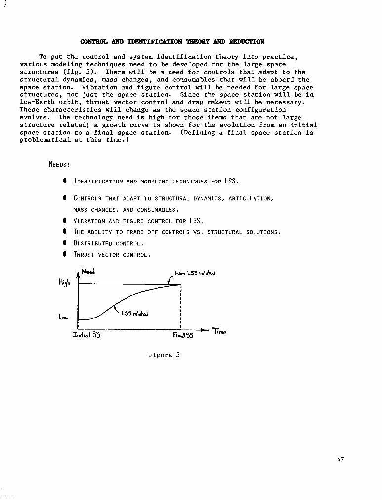
To pu t t he con t ro l and sys t em iden t i f i ca t ion t heo ry i n to p rac t i ce , various modeling techniques need t o be developed f o r t h e l a r g e s p a c e s t r u c t u r e s ( f i g . 5 ) . There w i l l be a need f o r c o n t r o l s t h a t a d a p t t o t h e s t r u c t u r a l dynamics, mass changes, and consumables that w i l l be aboard the space s t a t ion . V ib ra t ion and f i gu re con t ro l w i l l be needed f o r l a r g e s p a c e s t r u c t u r e s , n o t j u s t t h e s p a c e s t a t i o n . S i n c e t h e s p a c e s t a t i o n w i l l be in low-Earth o r b i t , t h r u s t v e c t o r c o n t r o l a n d d r a g makeup w i l l be necessary. T h e s e c h a r a c t e r i s t i c s will change as the space s t a t ion conf igu ra t ion evolves. The technology need i s h igh fo r t hose items t h a t are no t l a rge s t r u c t u r e r e l a t e d ; a growth curve is shown f o r t h e e v o l u t i o n f r o m a n i n i t i a l s p a c e s t a t i o n t o a f ina l space s t a t ion . (Def in ing a f i n a l space s t a t i o n i s p rob lema t i ca l a t t h i s time.)
NEEDS :
0
0
0 0 0 0
IDENTIFICATION AND MODELING TECHNIQUES FOR LSS,
CONTROL S THAT ADAPT TO STRUCTURAL DYNAMICS, ARTICULATION,
MASS CYANGESJ AND CONSUMABLESO
VIBRATION AND F I G U R E CONTROL FOR LSS, THE ABILITY TO TRADE OFF CONTROLS vs , STRUCTURAL SOLUTIONS, DISTRIBUTED CONTROL. THRUST VECTOR CONTROL,
F i g u r e 5
47

From a hardware standpoint, the needs (fig. 6 ) are in the areas of sensors to support docking and "smart" components. The interfaces between hardware and those between the controllers and the on-boar'd processing equipment must be standardized to support the guidance, navigation, and control technological evolution of the space station. "Clean" thrusters are required for optical payloads. Control moment gyros, integrated power and storage for attitude control, and even flywheels (which can now provide power as well as momentum to correct attitude) will be needed in the guidance, navigation, and control subsystem. The assessment of the time phasing shows a low need for the initial station but a high need for the later versions.
NEEDS : 0 AUTODOCKING SENSORS
0 RELATIVE ALIGNMENT SENSORS
0 "SMART" COMPONENTS
0 VIBRATION 8 FIGURE CONTROL HARDWARE
0 'TLEAN" THRUSTERS
0 GIMBAL SYSTEMS 0 CMG's 8 INTEGRATED
POWER AND STORAGE
4 Need
Figure 6
48

ANALYSIS Atm SPNTHESIS TOOLS
The guidance, nav€gat ion, and control technology requires analysis and syn thes i s t oo l s t o ana lyze t he pe r fo rmance of the thermal and controls systems and to i n t eg ra t e t he con t ro l s and t he s t ruc tu re . These r equ i r ed t oo l s are l i s t e d in f i g u r e 7. The time phasing of t h e t o o l s shows a moderate need f o r t h e i n i t i a l s p a c e s t a t i o n and a s t r o n g n e e d f o r t h e f i n a l s t a t i o n .
0 n E S I G N OF H I G H ORDER F U L T I I N P U T / OUTPUT CONTROL SYSTEMS
c NONLINEAR STRUCTURAL MODELS AND STRUCTURE SYNTHESIS I
CAD OF CONTROL SYSTEMS,
0 HUMERICAL TECHNIQUES,
a I E T H O D S FOR PAYLOAD COMMAND/TRACKING,
F i g u r e 7
49

SWSYSTEH AND SPACE STATION ADTONOMY
The space s t a t ion con t ro l and t he con t ro l of the various appendages need t o be autonomous (fig. 8). Th i s imp l i e s s e l f - con ta ined f a i lu re de t ec t ion and i s o l a t i o n ( i n c l u d i n g b u i l t - i n t e s t i n g ) . Work needs t o be done t o c h a r a c t e r i z e fa i lures , deve lop dec is ion-making cri teria r ega rd ing t he r econf igu ra t ion schemes tha t should be fol lowed to support on-orbi t repair by the crew and develop a computer-aided problem solving capabili ty. The last item, a r t i f i - cial i n t e l l i g e n c e , was l i s t e d w i t h mixed f e e l i n g among the pane l members. Some s k e p t i c s r e s i s t e d o r were r e l u c t a n t t o list a r t i f i c i a l i n t e l l i g e n c e because they were not sure of t h e d i r e c t i o n t h a t a r t i f i c i a l i n t e l l i g e n c e is taking. One key point was t h a t a grea t dea l o f money is being spent on a r t i f i c i a l i n t e l l i g e n c e , b u t t h e most s i g n i f i c a n t s t u d i e s are being made i n unfunded programs. The time phasing shows tha t the needs are l i g h t f o r a l l space s ta t ions planned.
NEEDS :
0 FORMALISM FOR AUTONOMOUS TESTING
0 FAILURE DETECTION, IDENTIFICATION AND RECONFIGURATION
0 COMPUTER AIDED PROBLEM SOLVING
0 ARTIFICIAL INTELLIGENCE
F i g u r e 8
50

DESIGN VERIFICATION PROCESS
The des ign ver i f ica t ion process poses a great problem to the guidance, navigation, and control technology because there i s no c u r r e n t method t o test a l a rge space s t ruc tu re o r i n t eg ra t ed gu idance , nav iga t ion , and con t ro l sys t em before launch ( f ig . 9). An a p p r e c i a t i o n of how to extrapolate f rom ground tes t to the space environment needs to be developed. Also, to generate a scheme f o r b e t t e r model v a l i d a t i o n , f l i g h t test experiments that w i l l begin v a l i d a t i n g t h e a n a l y t i c a l t o o l s need t o be designed. Likewise, a f l i g h t t e s t ing ph i lo sophy fo r t he space s t a t ion needs t o be i n i t i a t e d . T h i s p h i l o s - ophy needs to inc lude no t on ly in - f l igh t t es t ing on t h e e a r l y s p a c e s t a t i o n f l i g h t s , b u t a l s o t h e i n - f l i g h t t e s t i n g t h a t c a n be accomplished now wi th t he Shut t le and can la ter be t r a n s f e r r e d t o l a r g e s p a c e s t r u c t u r e s .
NFFDS: 0 AN APPRECIATION OF HOW GROUND TEST DATA CAN BE EXTRAPOLATED TO SPACE
0 MODEL VALIDATION (COMPUTER TOOL VERIFICATION)
0 INCREMENTAL VERIFICATION
ENVIRONMENT.
0 A FLIGHT TEST EXPERIMENT
0 I N F L I G H T T E S T I N G P H I L O S O P H Y FOR SPACE STATION
V
Figure 9
51

PAYLOAD POINTING
Payloads, and some of the s ta t ion appendages , may be a r t i c u l a t e d u s i n g ac t ive con t ro l sys t ems ( f ig . lo). Some missions may have several payloads, a l l of which may have independent pointing requirements. Disturbance isola- t i o n and decoupling, development of gimbal systems, and stationkeeping schemes may be payload dependent. The phasing i s dependent on t h e i n i t i a l m i s s i o n s f o r t h e s p a c e s t a t i o n s .
NEFDS : 0 DISTURBANCE ISOLATION AND DECOUPLING
8 COMMAND GENERATORS (FEED FORWARD CONTROL)
8 GIPRAL SYSTEMS
8 MULTIRATE SAMPLED DATA CONTRQL
0 STATIQN KEEPING
F i g u r e 10
52

NAVIGATION
The space station requires autonomous navigation (fig. 11). With Shuttle revisits and formation flying, traffic control and stationkeeping will impose navigational requirements. And, of course, disposal of the station at the end of its life m y be a consideration.
NEEDS: 0 AUTO NAVIGATION
4 TRAFFIC CONTROL @ STATION KEEPING
4 RE 8 DE BOOST
L ' / I I I
Figure 11
53
GUIDANtX, NAVIGATION, AND CONTROL TECHNOLOGY DEVELOPMENT CRITERIA
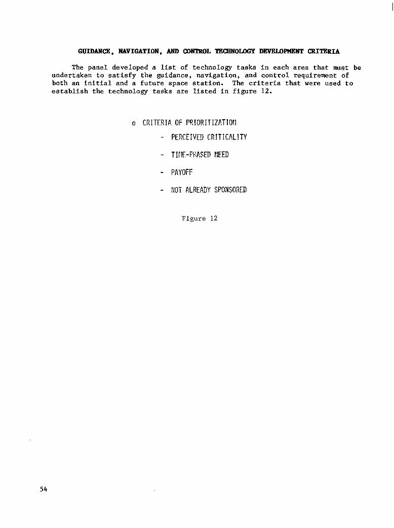
The panel developed a list of t echnology tasks in each area t h a t must be under taken to sa t i s fy the gu idance , naviga t ion , and cont ro l requi rement of b o t h a n i n i t i a l a n d a f u t u r e s p a c e s t a t i o n . The cri teria t h a t were used t o e s t ab l i sh t he t echno logy t a sks are l i s t e d i n f i g u r e 12.
o CRITFRIP. OF PRIORITIZ!,TIOII
- PERCEIVEJ CRITICALITY
- TII.1E-FtIRSED FEED
- PAYOFF
- !KIT ALREA3Y SFO?EORED
F i g u r e 12
54

GUIDANCE, NAVIGATION, AND CONTROL TEcHNoM)(=y DEVKLOmNT CANDIDATES : Synthesis/Analysis/Simlation
Cand ida te syn thes i s , ana lys i s , and s imula t ion tasks inc lude opera t iona l p l ann ing and t r a f f i c management, man ipu la to r con t ro l , s t ruc tu ra l dynamic c o n t r o l , and a t t i t u d e c o n t r o l ( f i g . 13). Of these, the development of a t t i - tude control technology is r e q u i r e d f o r t h e i n i t i a l s p a c e s t a t i o n t o p r o v i d e model ing and ident i f ica t ion of t h e s t r u c t u r e , momentum management, and modular and adapt ive control . The development of the o ther t echnologies is requ i r ed f o r f u t u r e s p a c e s t a t i o n s .
OPERATIONAL PLANN IblG AND TRAF- PROVIDES I NTER-VEH I CLE AND TRAF- F I C MANAGEMENT SYSTEM F I C CONTFOL, ALLOWS SAFE TERMINAL
RENDEZVOUS 8 DOCKING
MANIPULATOR CONTROL ENABLES OPERATIONS, EASES OPERATOR TASKS
STRUCTUAL DYNAMICS CWTSQL IMROVES PERFORMANCE FOR FLEXIBLE VEHICLE, PR0VIT)ES STABILITY, DAMPING, SHAPE CONTROL
o ATTITUDE CONTROL MODELING AND IDENTIF ICATION OF STRUC- TURE, MOMENTUN MANAGEMENT, MODULAR CONTROL, ADAPTIVE COMTROL
F i g u r e 13
55

GUIDANCE, NBVIGATION, AND CONTROL TECEINOLOGY DEVELOPHENT CANDIDATJB : &rdware/Coq?onents
Hardware and components t a s k s are l i s t e d i n f i g u r e 14. The development of docking sensor , in terface, and point ing moment technology is r equ i r ed i n i t i a l l y . Development of p o i n t i n g mounts may r e l i e v e some of t h e i n i t i a l space s t a t ion r equ i r emen t s (p rov ide t o rqu ing equ i l ib r ium o r i en ta t ion ) . I f t he i n i t i a l missions o r i n i t i a l r e q u i r e m e n t s f r o m t h e p a y l o a d u s e r s d i c t a t e , i s o l a t i o n d e v i c e s may be needed f o r t h e e a r l y s p a c e s t a t i o n s .
o IMPROVED CMG
o DOCKING SENSOR/ INTERFACE
o ADVAflCEII RELATITVE NAVIGP,TION SENSOR
o ATTITUDE TRANSFER IIEV ICES
o INTEGRATED ENERGY/ MOMENTUM MANAGEMENT SYSTEM
o POINTING VOUNTS
o ISOLATION DEVICES
o AUTONOYY
o ON-BOAR3 NAVIGATIOP4
LOWER COST, LONGER LIFE, IMPROVED MOMENTUM IIEWSITY
SAFETY, OPERABILITY
TRAFFIC MANAGEMENT, EXTENDED RANGE, M I N I - MIZE VEtI ' ICLE COPJSTRAINTS, PROPELLANT RE- DUCTION
IMPROVED EXPERIMENT P O I N T I K , ALLOWS CEN- TRALIZED ATTITUDE LIETERMINATI9N
WEIGHT SAVINGS
FACILITATES EXPERIMENT POINTING, RELIEVES SS PO I N T I NG RESU I REMENTS, ALLO'IS PAY LOAD VIEWING/POINTING, IYPRO?ES PERFORMANCE
PIPROVES EXPER IYENT PERFORPlANCE
PROVIqES SAFETY, OPERATIONAL EN- HAWCEMENT, C?ST
SAFETY, CC)ST
Figure 14
56

GUIDANCE, NAVIGATION, AND CONTROL TKcHN0uX;y DEVELOPMENT CANDIDATJIS: Design Verification
The des ign ver i f ica t ion tasks address the key problem of sys tem in te rac- t i o n s between s t ruc tu res and con t ro l s ( f i g . 15). Ground test f a c i l i t i e s w i l l be needed and need t o be generic (not developed for a spec ia l i zed space s t a t i o n ) . E x i s t i n g f a c i l i t i e s a n d g r o u n d test beds can be ut i l ized but may requi re upgrading . Dedica ted o rb i ta l tests are required to support concept v e r i f i c a t i o n , and o r b i t e r o p p o r t u n i t y tests should be conducted to take advantage of the S h u t t l e ' s low c o s t f l i g h t v e r i f i c a t i o n .
o GROUND T E S T F A C I L I T I E S - RESEARCH ORIENTED, PROOF OF GENER IC THEORY ( S C I E N T I F I C METHOD)
o GROUND TEST BEDS PROJECT 9RIENTEDJ SIMULATION, t!ARD!!ARE TEST, SYSTEP? VER I F I CA- T I ON
O DEDICATED ORBITAL TESTS VERIFICATION OF CONCEPTS, STRUC- TURAL TESTING, 0-G TESTING, FREE FLYERS
O ORCITER OPPORTUNITY TESTS Lob!-COST TECl.!NOLOGY VERIFICATIOFi
Figure 15
57
PROPOSED !PACE STATION TEcHNoLoGp DEVELOPPENT GROUND RULE
With a l l the concern over funding, the panel developed a ground r u l e f o r space s ta t ion technology development ( f ig . 16) . F i r s t , a cr i t ica l funding leve l should be es tab l i shed for each pr ior i t ized technology deve lopment t ask . Second, i f t h e t a s k c a n n o t be funded t o i t s cr i t ical r e s e a r c h l e v e l , i t should not be i n i t i a t e d .
0 ESTABLISH A CRITICAL FUI~DI~YG LEVEL REQUIRED FOR EACH PRIORIT IZED
TECHdOLOGY DEVELOPMENT TASK
0 I F YOU CANNOT FUND A TASK TO ITS C R I T I C A L RESOURCE LEVEL ------- DO 1d0T DO I T ! ! !
Figure 15
58
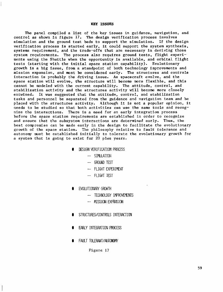
KEY ISSUES
The panel compiled a list of the key i s sues in gu idance , naviga t ion , and c o n t r o l as shown i n f i g u r e 17. The des ign ver i f ica t ion process involves simulation and the ground test beds t o s u p p o r t t h e s i m u l a t i o n . I f t h e d e s i g n v e r i f i c a t i o n p r o c e s s is s t a r t e d e a r l y , i t could suppor t the sys tem synthes is , systems requirement , and the t rade-offs that are n e c e s s a r y i n d e r i v i n g t h o s e system requirements. The process a l so requi res g round tests, f l i g h t e x p e r i - ments using the Shut t le when the opportuni ty is a v a i l a b l e , a n d o r b i t a l f l i g h t tests ( s t a r t i n g w i t h t h e i n i t i a l s p a c e s t a t i o n c a p a b i l i t y ) . E v o l u t i o n a r y growth is a b ig i s sue , f rom a s tandpoin t of both technology improvements and mission expansion, and mst be considered early. The s t r u c t u r e s and c o n t r o l s i n t e r a c t i o n is probably the dr iving issue. A s spacecraf t evolve, and the s p a c e s t a t i o n w i l l evo lve , t he s t ruc tu re w i l l become more f l e x i b l e , and t h i s cannot be modeled wi th the cur ren t capabi l i ty . The a t t i t u d e , c o n t r o l , a n d s t a b i l i z a t i o n a c t i v i t y a n d t h e s t r u c t u r e s a c t i v i t y w i l l become more c lose ly entwined. It was s u g g e s t e d t h a t t h e a t t i t u d e , c o n t r o l , and s t a b i l i z a t i o n tasks and personnel be separated from the guidance and navigation team and be p l aced w i th t he s t ruc tu res ac t iv i ty . A l though it i s not a popular opinion, i t needs t o be s tud ied so t h a t b o t h a c t i v i t i e s c a n u s e t h e same t o o l s and recog- n ize the in te rac t ions . There is a need fo r an ea r ly i n t eg ra t ion p rocess before the space s ta t ion requi rements are e s t a b l i s h e d i n o r d e r t o r e c o g n i z e and ensure that the subsystem interact ions are determined ear ly . Thus, the b e s t compromise can be made e a r l y i n t h e d e s i g n t o f a c i l i t a t e t h e e v o l u t l o n a r y growth of t he space s t a t ion . The ph i losophy r e l a t ive t o f au l t t o l e rance and autonomy mst be e s t a b l i s h e d i n i t i a l l y t o t o l e r a t e t h e e v o l u t i o n a r y g r o w t h f o r a system that is g o i n g t o e x i s t f o r 20 plus years .
0 DESIGN VERIFICATION PROCESS -- SIMILATIOil -- GROUtD TEST -- FLIGHT D(F€RIWfl -- FLIGHT TEST
0 EVOLUTIOMRY G R W l H -- TECHMLOGY I M P R O W ~ S -- MISSION EXPNiSIOR
0 STRUCTUWCOIJTROLS INTER4CTIOW
0 EARLY INTEGRATION PROCESS
0 FAULT T O L E W . W T / A U T O ~
F igure 17
59

PROPOSED NASA-INDUSTRY CloOBDINATKD PLA?WING
The panel p roposed severa l ac t iv i t ies des igned to enhance coord ina ted NASA-industry planning on t h e s p a c e s t a t i o n ( f i g . 18). A NASA s p a c e s t a t i o n summary repor t , publ i shed every 6 months and i n c l u d i n g r e s u l t s a n d / o r p r o g r e s s r e p o r t s on in-house and contract system s tudies , would keep industry abreast of t h e c u r r e n t s t a t u s of space s t a t ion ac t iv i ty . Cur ren t ly , t he Depa r tmen t o f Defense (DOD) v i s i t s v a r i o u s i n d u s t r y p l a n t s t o p a r t i c i p a t e in the Independent Research and Development (IRAD) review cycle. NASA p a r t i c i p a t i o n i n t he IRAD review cycle would g e n e r a t e i n d u s t r y v i s i b i l i t y f o r NASA, as well as NASA v i s i b i l i t y f o r i n d u s t r y , w i t h t h e r e s u l t t h a t NASA would have an increased impact on industry. Also, better communications between NASA and DOD would be established, which would allow some synergism in technology budgets . Final ly , NASA-industry s p a c e s t a t i o n workshops such as t h e c u r r e n t one should be he ld p e r i o d i c a l l y .
I NASA SPACE STATION SUMYA4Y P.ED0P.T
- - 513 PAGES
- PUBLISH EVERY 6 YONTHS
- INCLUDE RESULTS OF SYSTEY STUDIES, IN-HOUSE AND CONTRACTED RESEP.?CH
- ESTABLISH FORMAT TO MAKE INPUTS EASY
- INCLUDE REPORT REFERENCE L I S T
NASA P A R T I C I P A T E I N DOD IQAD REVIEW
- V I S I B L I T Y TO INDUSTRY AND V I C E VERSA
- NASA IYPACT IMI)UST!?Y AND V I C E VERSA
- COMMUNICATION bl ITH DOD
NASA/INDUSTRY SPACE STATION !IORKSHO? PERIODICALLY
Figure 18
60

TlUMAN CAPABILITIES
William Augerson Arthur D. L i t t le
Cambridge, Massachusetts
Space Station Technology Workshop Williamsburg, Virginia
March 28-31, 1983
61

MAN IS A CRITICAL DESIGN ELEMENT
I f you are going to have a manned space s t a t i o n , man is a d r i v e r i n t h e system design (fig. 1). It i s doubtful that anyone w i l l accept the Greek idea t h a t man is a measure of a l l th ings , bu t hopefu l ly a l l w i l l a c c e p t t h e f a c t t h a t t h e crew is a major system and hence a c r i t i c a l design element i n t h e space s t a t ion . Even without man on t he space s t a t ion , t e l eope ra to r s and a man-machine i n t e r f a c e would e x i s t .
The o b j e c t i v e of human capab i l i t i e s t echno logy i s t o maximize t h e human/system p r o d u c t i v i t y t o meet the customer's requirements.
b
SPACE STATION
I I MANNED
CREW IS TELEOPERATORS CRITICAL MAN-MACHINE INTERFACE
DES I GN ELEMENT
OBJECTIVE: MAXIMIZE HUMAWSYSTEM PRODUCTIVITY (CUSTOMER REQUIREMENT)
F i g u r e 1
62

BACKGROUND
People do no t r ea l ly app rec i a t e t he r ange of performance of t h e human v i sua l ana lyze r (man) ( f i g . 2). Robotics technology i s s t i l l f a r from captur- i n g t h e f l e x i b i l i t y and adap tab i l i t y of the opposable thumb, the ear, the eye , o r t h e human brain. A s a matter of f a c t , humans are very strong. Omnivores are soc ia l c r ea tu res and work w e l l i n teams. They use language, use tools , and inver t t asks . The spec ie s is a s p e c i a l i s t i n d i v e r s i t y .
Ten thousand years ago, homo sap iens w a s on a l l p a r t s of t h e E a r t h , except Antarc t ica . H e was l i v i n g and working 3 miles high and had f lourishing communities around the Arctic Ocean and i n many d e s e r t areas. Later, he took t o t h e sea, then the a i r , and now space. Homo sap iens is an explorer.
The r ecen t h i s to ry of p u t t i n g man i n complex systems, however, has tended t o emphasize t h i s human v e r s a t i l i t y and a d a p t a b i l i t y as a buf fer to cope wi th some of the shortcoming of some eng inee r ing subsys t ems t o fu l f i l l a l l of t h e i r ear ly design promises . Those t rades were made because t h e community could not prove that man would f a i l . I n d e e d , t h e r e l a t i v e l y r e c e n t h i s t o r y of Skylab showed once again how man could save the entire system, and how human a d j u s t - ments made t h e d i f f e r e n c e i n t h e s c i e n t i f i c p r o d u c t i v i t y of t h a t o p e r a t i o n . Some s u b s t a n t i a l r e a r r a n g i n g of philosophy needs to be made. The bottom l i n e i s tha t t he crew is ready and tes ted, but the factory and tools need more work.
A
8
8
8
HUMAN OPERATING CHARACTERISTICS
ANCIENT HISTORY
RECENT ti ISTORY
8 THE CREW I S READY AND TESTED, THE TOOLS AND FACTORY NEED SOME WORK,
F i g u r e 2
63

CONSIDERATIONS
Severa l i s sues need t o be addressed in cons ider ing the t echnology development in human c a p a b i l i t i e s f o r a space s t a t i o n ( f i g . 3 ) . Given t h a t t he po ten t i a l mi s s ion of a s t a t i o n is q u i t e d i v e r s e , t h e i s s u e of p r o d u c t i v i t y becomes a star t o s teer by. It i s impor tan t to cons ider no t on ly human pro- d u c t i v i t y b u t a l s o t h e p r o d u c t i v i t y of humans us ing devices . The dura t ion of t h e work d u t y c y c l e i n t h e s t a t i o n as w e l l as t h e l i f e of t h e s t a t i o n are both a problem and an opportunity. Certainly, the longer the duration, the less clamor there w i l l b e , a n d t h e g r e a t e r t h e s e n s i t i v i t y t o h a b i t a b i l i t y problems. A t t he same time, t h e r e are some subs t an t i a l env i ronmen ta l engineer ing and hea l th i s sues tha t are imbedded in l ong du ra t ion . From t h e i n d u s t r i a l w o r l d , t h e r e is considerable knowledge about threshold limit va lues for various chemicals. These values are genera l ly deve loped for a 40-hour work week (8-hour day) f o r one chemical. When a 3-month s t a y (24-hour day) a t a s p a c e s t a t i o n f o r a crew and a v a r i e t y of chemicals in the environment is cons idered , the habi tab i l i ty p roblem becomes more complex. D ive r s i ty is a l s o a key consideration. It is important to maximize the number of customers ( u s e r s ) and they w i l l need to per form a v a r i e t y of func t ions . Therefore , i t i s impor t an t no t t o fo rec lose op t ions i n human p a r t i c i p a t i o n t o o r a p i d l y . Likewise, wi th growth and f lexibi l i ty , man's capabi l i ty should no t be t r aded o f f ea r ly .
PRODUCTIVITY
DURATION
DIVERSITY - EISSIOfVFUNCTION WORK FORCE
GROWTH AND FLEX I B I L I TY
Figure 3
64
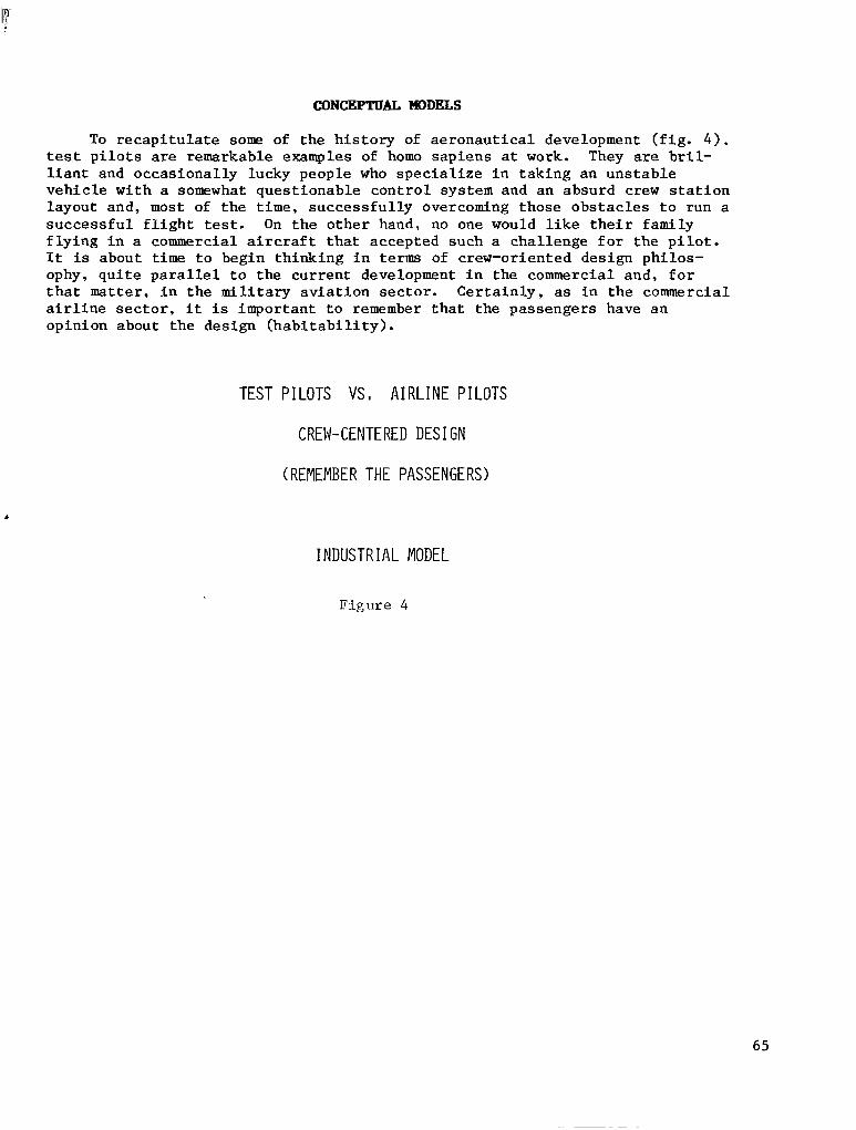
CONCEPTUAL MODELS
To r e c a p i t u l a t e some of t h e h i s t o r y of aeronaut ical development ( f ig . 4 ) . test p i l o t s are remarkable examples of homo sap iens a t work. They are b r i l - l i a n t and occasionally lucky people who s p e c i a l i z e i n t a k i n g a n u n s t a b l e v e h i c l e w i t h a somewhat questionable control system and an absurd crew s t a t i o n layout and, most of t h e time, successfu l ly overcoming those obs tac les to run a s u c c e s s f u l f l i g h t test. On the other hand, no one would l i k e t h e i r f a m i l y f l y i n g i n a commercial a i r c r a f t t h a t a c c e p t e d s u c h a c h a l l e n g e f o r t h e p i l o t . It is about time t o b e g i n t h i n k i n g i n terms of crew-oriented design philos- ophy, qu i t e pa ra l l e l t o t he cu r ren t deve lopmen t i n t he commerc ia l and , fo r t h a t matter, i n t h e m i l i t a r y a v i a t i o n s e c t o r . C e r t a i n l y , as i n t h e commercial a i r l i n e s e c t o r , i t is impor t an t t o remember that the passengers have an op in ion abou t t he des ign (hab i t ab i l i t y ) .
TEST PILOTS VS, AIRLINE PILOTS
CREW-CENTERED DES1 GN
(REMEMBER THE PASSENGERS)
A
INDUSTRIAL MODEL
F i g u r e 4
65

Analogs were mentioned ear ly in the panel session. The panel considered them t o be very important and very numerous (fig. 5). A t t h e same time, t h e s e experiences are not well compiled or easy to get to . It is impor tan t tha t NASA begin digging out these data . NASA i s good a t i l l u m i n a t i n g s o c i a l and env i ronmen ta l i s sues t ha t ex i s t . A c l a s s i c example is t h e l o c a t i o n of comfort f a c i l i t i e s i m m e d i a t e l y a d j a c e n t t o d i n i n g f a c i l i t i e s in A n t a r t i c s t a t i o n and m i l i t a r y f i e l d s t a t ions.
0
0
i n s t a l l a t ions and , un le s s -changes are made, i n f u t u r e s p a c e
VERY I PIPORTANT
VERY NUMEROUS
NOT COKP I LED
ILLUMINATE SOCIAL/ENVI RONMENTAL/OPERATION ISSUES
"COMPANY TOWN YITH AN INTERNATIONAL AIRPORT I N ORBIT"
F i g u r e 5
66

The human c a p a b i l i t i e s p a n e l was divided into three working group teams, as shown in f i g u r e 6 . The medical, physiology, psychology, and human f a c t o r s e x p e r t s were g r o u p e d i n t o h a b i t a b i l i t y . In work performance, the classic i n t e r e s t g r o u p s in human performance were merged with people in t e l e o p e r a t o r s and r o b o t i c s , IVA and EVA ( o f t e n f a l s e l y p o r t r a y e d as competi tors) . And t h e man-machine i n t e r f a c e team was a f a i r l y t r a d i t i o n a l one.
0 HABITABILITY
0 WORK PERFORMANCE (IVA/EVA/TELEOPERATORS)
0 MAN-MACH I NE I NTERFACE
F i g u r e 6
67

TECENOLWY STATUS
The panel assessed the t echnology s ta tus of h a b i t a b i l i t y t e c h n o l o g y , as shown i n f i g u r e 7. A comprehensive and integrated approach perhaps has not been accomplished because a l l the answers about how t o do it are not known. This suggests that operat ing in space does pose some cha l lenges to the people who have to l i v e and work on the space s t a t ion .
AN I NTEGRATED AND COMPREHEFIS I VE
APPROACH TO HABITABIL ITY
HAS YET TO BE DONE
F i g u r e 7
68
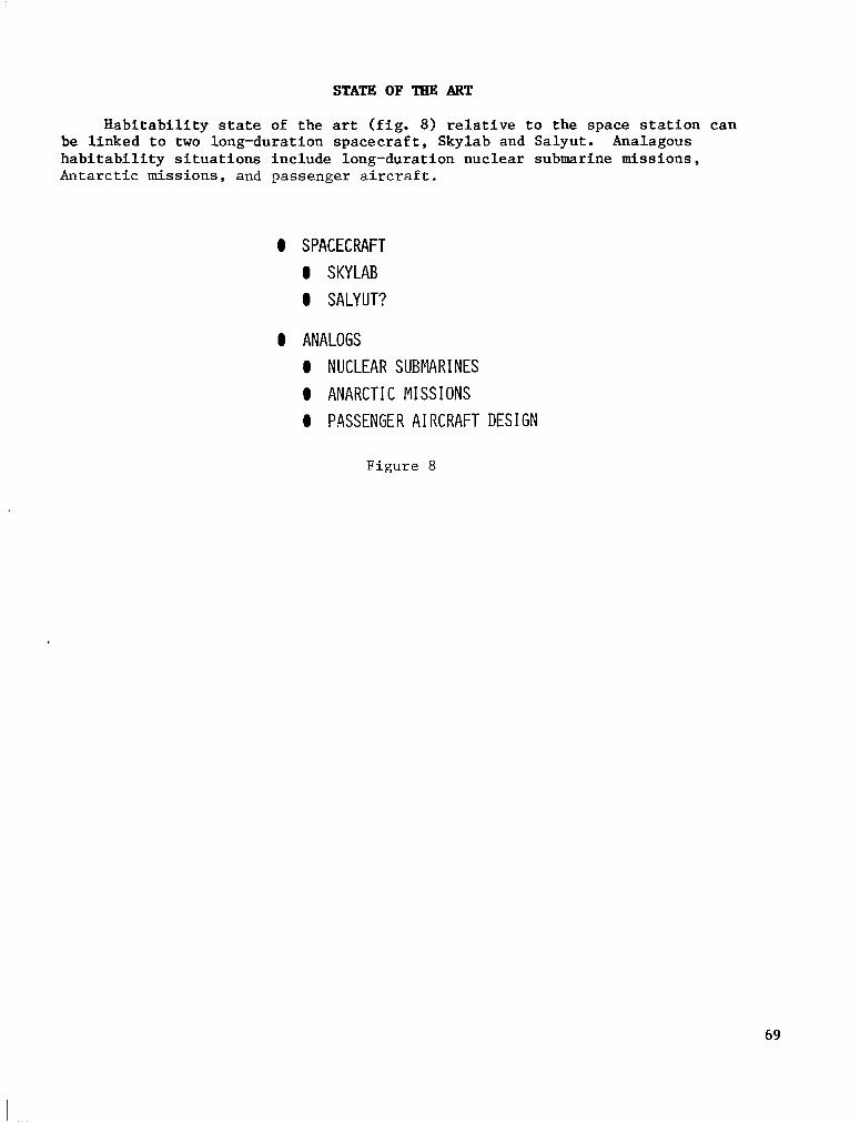
STATE OF TEE ART
Habitability state of the art (fig. 8) relative to the space station can be linked to two long-duration spacecraft, Skylab and Salyut. Analagous habitability situations include long-duration nuclear submarine missions, Antarctic missions, and passenger aircraft.
0 SPACECRAFT 0 SKYLAB 0 SALYUT?
0 ANALOGS 0 NUCLEAR SUBMARINES 0 ANARCTIC MISSIONS 0 PASSENGER AIRCRAFT DESIGN
Figure 8
69
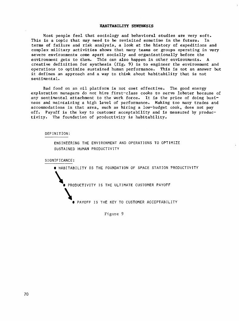
I
HABITABILITY SYNTHESIS
Most peop le f ee l t ha t soc io logy and behaviora l s tud ies are ve ry so f t . This is a t o p i c t h a t may need t o be r e v i s i t e d sometime i n t h e f u t u r e . I n terms of f a i l u r e and r i s k a n a l y s i s , a look at t h e h i s t o r y of expedi t ions and complex m i l i t a r y a c t i v i t i e s shows t h a t many teams or g roups opera t ing in very severe environments come a p a r t s o c i a l l y and o rgan iza t iona l ly be fo re t he environment gets to them. This can a lso happen in other environments . A c r e a t i v e d e f i n i t i o n f o r s y n t h e s i s ( f i g . 9) is to engineer the environment and opera t ions to op t imize sus ta ined human performance. This i s not an answer but i t defines an approach and a way t o t h i n k a b o u t h a b i t a b i l i t y t h a t is not sen t imenta l .
Bad food on a n o i l p l a t f o r m is no t cos t e f f ec t ive . The good energy exp lo ra t ion managers do no t h i r e f i r s t - c l a s s cooks t o s e rve l obs t e r because of any sen t imenta l a t tachment to the work force. It i s t h e p r i c e of doing busi- ness and maintaining a h igh leve l of performance. Making too many t rades and accommodations i n t h a t area, such as h i r i n g a low-budget cook, does not pay off. Payoff is the key to customer acceptabi l i ty and i s measured by produc- t i v i t y . The foundat ion of p roduc t iv i ty is h a b i t a b i l i t y .
D E F I N I T I O N :
E N G I N E E R I N G T H E E N V I R O N M E N T A N D O P E R A T I O N S T O O P T I M I Z E
S U S T A I N E D HUMAN P R O D U C T I V I T Y
S I G N I F I C A N C E :
0 H A B I T A B I L I T Y IS T H E F O U N D A T I O N O F S P A C E S T A T I O N P R O D U C T I V I T Y
I 0 P R O D U C T I V I T Y I S T H E U L T I M A T E C U S T O M E R P A Y O F F
1 0 PAYOFF I S THE KEY TO CUSTOMER ACCEPTABIL ITY
F i g u r e 9
70

HODEL PROCESS
Ins t ead of j u s t l i s t i n g t h e h a b i t a b i l i t y t e c h n o l o g y i s s u e s , a model process was e s t a b l i s h e d ( f i g . 10) t n t h e e v e n t t h a t a process problem was imbedded i n some of t h e d i f f i c u l t i e s t h a t e x i s t e d . T h i s model process goes beyond t h e u s u a l "Give them a handbook and maybe they w i l l read i t" concept. Handbooks are a lmost ins tan t ly ou t of d a t e i n t h i s area. It would be t o NASA's a d v a n t a g e t o e s t a b l i s h a process whereby hab i t ab i l i t y t echno logy i s sues are d e t e c t e d f a i r l y e a r l y from the various sources. There should be a l i v i n g handbook embedded i n t h e p r o c e s s so t h a t t h e e f f o r t g o e s somewhere.
PROCESS SOURCES
0 I N P U T S : E M E R G I N G H A B I T A B I L I T Y I S S U E S F L I G H T O P E R A T I O N S
I N PROPOSED ARCHITECTURES FL IGHT EXPERIMENTS
CREW I N P U T S
0 S P E C I F I C A T I O N S : D E V E L O P M E N T O F H A B I T A B I L I T Y P A S T E X P E R I E N C E
REQUIREMENTS ANALOGS
GROUND S I M U L A T I O N S
I M P L E M E N T A T I O N S T R A T E G I E S PANELS/CONSULTANTS 0 A C T I O N S :
Figure 10
71
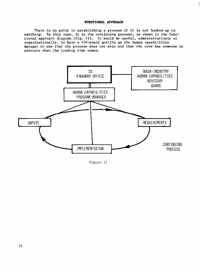
FUNCTIONAL APPROACH
There is no point in establishing a process if it is not hooked up to anything. I n this case, it is the continuing process, as shown in the func- tional approach diagram (fig. 11). It would be useful, administratively or organizationally, to have a 450-pound gorilla as the human capabilities manager to see that the process does not stop and that the crew has someone as advocate when the trading time comes.
ss 1-1 HUMAN CAPABILITIES I PROGRATI OFFICE I NASA- INDUSTRY
ADVISORY BOARD 1 I HUMAN CAPABILITIES
I
PROGRAM MANAGER I
I I N PUTS
CONTINUING IMPLEMENTATION PROCESS
Figure 11
72

HABITABILITY CATEGORIES
The h a b i t a b i l i t y c a t e g o r i e s set f o r t h by t h e i n i t i a l NASA working group are shown i n f i g u r e 12 and are cur ren t ly conceptua l ly s t ruc tured . The panel conc luded t ha t t hese ca t egor i e s were necessary but a long way from s u f f i c i e n t . A s a matter of f a c t , any one of those topic headings i s a major subcontinent f o r e x p l o r a t i o n i n i t s own r i g h t . The c a t e g o r i e s set f o r t h by t h e p r e s e n t workshop are l i s t e d t o p o i n t o u t t h e e n o r m i t y of s y n t h e s i s t h a t is going to be requi red , bo th of t he rest of the program and of t h e community. Some of t h e i s s u e s d r i v e n by duration have been discussed. Consider acoustics f o r a moment. Acoustics i s a heal th problem, among other things. For a h i g h l e v e l o f n o i s e i n a n i n d u s t r i a l o p e r a t i o n , a handbook w i l l p rovide the maximum exposure allowed by the Occupational Safety and Health Administration. However, t h e handbook does not say anything about the health consequence of a s teady week o r a yea r a t tha t l eve l . The re is i n s u f f i c i e n t time and money t o f i l l i n t h o s e d a t a p o i n t s . On the o ther hand , acous t ics (at a high noise l e v e l ) is a s l eep and ope ra t iona l e f f ec t iveness i s sue as well as a communica- t i o n i s s u e . It i s a n o p e r a t i o n a l i s s u e i n terms not only of p roduc t iv i ty bu t a l s o of g l i t ches i n t he ope ra t ion ( example : someone thought you s a i d "no" and you s a i d "go"). Acoustics i s a s o c i a l i s s u e t o o . I f you have t o y e l l a t someone every time you want something, i t ge ts annoying a f te r a while. There are s e r i o u s and d i f f i c u l t i m p l i c a t i o n s i n s e t t i n g a c o u s t i c s t a n d a r d s f o r enviromental control system design, sui t design, communicat ions, crew s t a t i o n , power, and structure. NASA w i l l have to deve lop a p rocess fo r making some of t h e s e t r a d e s i n a way t h a t i n c r e a s e s , i n s t e a d of decreases , p roduct iv i ty .
U I T I A L NASA WORKING GROUP FOOD SYSTEM TECHNOLOGY DECONTAMINATION TECHNOLOGY MEDICAL CARE VIBROACOUSTT c ENVIRONMENT CONTROL HUMAN PERFORMANCE ASSESSMENT (HISTORICAL)
PRESENT lORKSHOP INTERIOR DESIGN/LAYOUT DEBRIS/CONTAMINATION/WASTE CONTROL/~~ANAGEMENT MEDICAL/EMERGENGY CARE - SAFE HAVENS ENVIRONMENTAL - ACOUSTIC, LIGHTING. ETC, -- (INCLUDED IN PROCESS) PREVENTIVE/~~EDICAL COUNTERMEASURES WORK/REST CYCLES - RECREATIONKREW ROTATION MAINTENANCE/TRAINING COMMAND/CONTROL/ROLE RELATIONIGOVERNMENT SOCIAL STRUCTURE/COMMUN I TY HI ERARCHY
HOUSEKEEPING COMMUNICATIONS STORAGE/~NVENTORY PERSONAL HYGIENE AUTONOMY EVA/ I VA RESTRAINT~MOBILITY
Figure 12
73

ISSUES
The p a n e l ' s p r e s c r i p t i o n was to conduct a comprehensive assessment of habi tab i l i ty t echnology and the many i s s u e s imbedded i n it ( f i g . 13) . The assessment of these topics suggests the magni tude of that agenda and i t has been recommended t h a t i t be approached organiza t iona l ly . However, the problem is la rge enough to have an adminis t ra t ive focus so t h a t i t does no t ge t d i f fused and l o s t .
0 CONDUCT COKPREHENSIVE ASSESSMENT OF HABITABILITY
0 CONSOLIDATE RESPONSIBILITY FOR HUMAN CAPABILITIES WITH I N PROGRAM OFF ICE ,
Figure 13
74
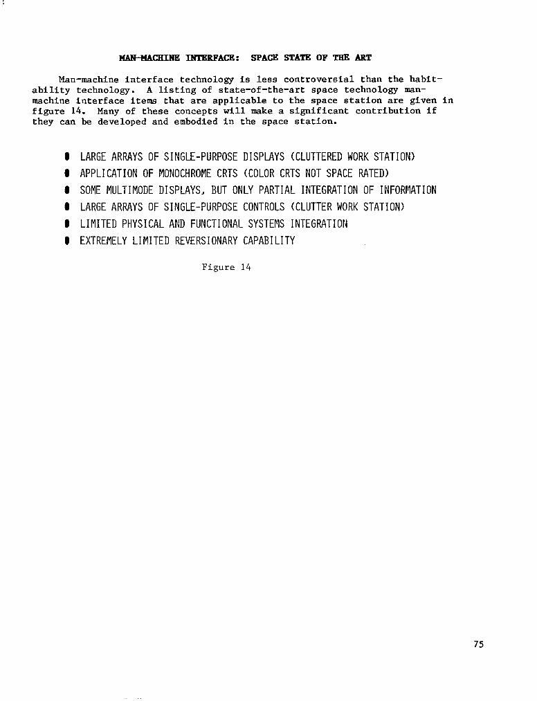
MAN-WICHINE INTERFACE: SPACE STATE OF TEE ART
Man-machine interface technology is less controversial than the habit- ability technology. A l i s t i n g of state-of-the-art space technology man- machine interface items that are applicable to the space station are given in f igure 14. Many of these concepts w i l l make a significant contribution i f they can be developed and embodied i n the space station.
0 LARGE ARRAYS OF SINGLE-PURPOSE DISPLAYS (CLUTTERED WORK STATION) 0 APPLICATION OF MONOCHROME CRTS (COLOR CRTS NOT SPACE RATED) 0 SOME MULTIMODE DISPLAYS, BUT ONLY PARTIAL IFiTEGRATION OF IiFORMATION 0 LARGE ARRAYS OF SINGLE-PURPOSE CONTROLS (CLUTTER WORK STATION) @ LIMITED PHYSICAL AND FUNCTIONAL SYSTEMS INTEGRATION 0 EXTREMELY LIMITED REVERSIONARY CAPABILITY
F i g u r e 14
75
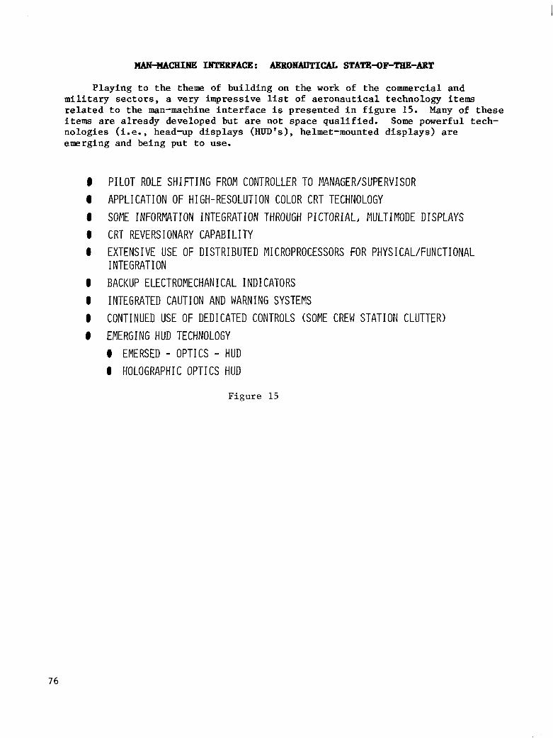
MAN+ACHINE INTERFACE: dgBON4DTICAL STATE4F-TEE-ART
P l a y i n g t o t h e theme of bu i ld ing on t h e work of the commercial and m i l i t a r y s e c t o r s , a very impressive list of aeronaut ica l t echnology items r e l a t e d t o t h e man-machine i n t e r f a c e is p r e s e n t e d i n f i g u r e 15. Many of t h e s e items are already developed but are not space qua l i f ied . Some powerful tech- no log ie s (i.e., head-up displays (HUD's), helmet-mounted d i s p l a y s ) are emerging and being put to use.
PILOT ROLE SHIFTING FROM CONTROLLER TO MNAGER/SUPERVISOR APPLICATION OF HIGH-RESOLUTION COLOR CRT TECHNOLOGY SOME INFORPATION INTEGRATlON THROUGH PICTORIAL, PIULTIMODE DISPLAYS CRT REVERSIONARY CAPABILITY EXTENSIVE USE OF DISTRIBUTED MICROPROCESSORS FOR PHYSICAL/FUNCTIONAL I NTEGRAT I ON BACKUP ELECTROMECHANICAL INDICATORS INTEGRATED CAUTION AND WARN I NG SYSTEES CONTINUED USE OF DEDICATED CONTROLS (SOME CREM STATION CLUTTER) EMERGING HUD TECHNOLOGY 0 EMERSED - OPT1 CS - HUD 0 HOLOGRAPHIC OPTICS HUD
Figure 15
76

BENEFITS OF GENERIC WORK STATION
Although the latest Boeing a i rc raf t does have a l i t t l e less e x c i t i n g r een t ry p rob lem than t he Shu t t l e , i t is a crew s t a t i o n t h a t h a s been designed f o r s i m p l i c i t y and t o s u p p o r t t h e crew. Such is not the case f o r t h e s p a c e s t a t i o n . The i d e a of a g e n e r i c o r g e n e r a l i z e d work s t a t i o n , p a r t i c u l a r l y when coupled with an all-class s t a t i o n ( a n i n t e r a c t i v e d i s p l a y ) , would provide many b e n e f i t s t o t h e s p a c e s t a t i o n , as shown i n f i g u r e 16. The g e n e r i c work s t a t i o n c o u l d a l s o be r e a d i l y moved around as needed a t d i f f e r e n t p a r t s of t h e space s t a t ion and would be adaptab le to bo th sc ien t i f ic and commerc ia l payloads.
0 REDUCED COST I H DES1 GN AND PRODUCTION
a MINIKIZES RETRAINING/CROSSTRAINING
0 ENHANCES SAFETY THROUGH REDUNDANCY/BACK-UP
Figure 16
77

ENABLING TECEINOLWY DEVELOPMENT NEEDS
Enabling technology development needs f o r a space-rated generic workshop are l isted i n figure 17.
0 0 0 8 0 0
0
0
LARGE SCREEN DISPLAYS MULTI-FUNCTION CONTROLS DISTRIBUTED PROCESSING/BUSSING FOR PIULTI-LOCATION OPERATION DEFINE AND IPIPLEMENT AN ALL-GLASS INTEGRATED MULTIMODE TESTBED GUIDELINES AND STANDARDS FOR DESIGN CKEN HELMET WITH HUD
MODELING OF MAN AS ELEMENT I N AN INFORMATION-PROCESSING NETWORK WORK TOWARD APPROPRIATE "NATURAL LANGUAGE" FOR MAN-MACHINE INTERFACE AUTOMATIC ACQUISITION OF DATA BASE FOR KNO)!LEDGE-BASED SYSTEMS
F i g u r e 17
78
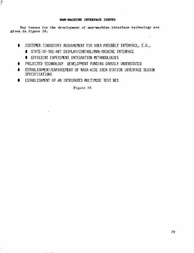
Key i ssues for the deve lopment of man-machine in te r face t echnology are g i v e n i n f i g u r e 18.
@ CUSTOMER (INDUSTRY) REQUIREMENT FOR USER FRIENDLY INTERFACE, E. G., # STATE-OF-THE-ART DISPLAY/CONTROL/MAN-MCHINE INTERFACE 8 EFFICIENT EXPERIMENT INTEGRATION METHODOLOGIES
0 PROJECTED TECHNOLOGY DEVELOPMENT FUNDING GROSSLY UNDERSTATED ESTABLISHMENT/ENFORCEMEMT OF NASA-WIDE CREW STAT1 ON INTERFACE DES1 GN SPECIFICATIONS ESTABLISHMENT OF AN INTEGRATED MULTIMODE TEST BED
Figure 18
79
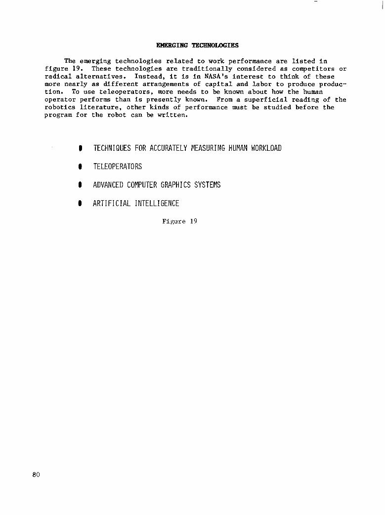
EMERGING TECEINOLWIES
The emerging technologies re la ted to work performance are l i s t e d i n f i g u r e 19. These technologies are t r a d i t i o n a l l y c o n s i d e r e d as compet i tors o r r a d i c a l a l t e r n a t i v e s . I n s t e a d , i t is i n NASA's i n t e r e s t t o t h i n k of t hese more nea r ly as d i f fe ren t a r rangements of capi ta l and labor to p roduce produc- t i o n . To use t e l eope ra to r s , more needs t o be known about how t h e human operator performs than is p r e s e n t l y known. From a s u p e r f i c i a l r e a d i n g of t h e r o b o t i c s l i t e r a t u r e , o t h e r k i n d s of performance must be s tud ied be fo re t he program for the robot can be wr i t t en .
1 TECHNIQUES FOR ACCURATELY MEASURING HUMAN WORKLOAD
0 TELEOPERATORS
0 ADVANCED COMPUTER GRAPHICS SYSTEMS
0 ART1 F I C I A L I FITELLI GENCE
Figure 19
80

ENABLING TEcHNoLoG!z REQnIlm4FxTs
The requirements for work performance enabling technology are l i s t e d i n figure 20.
0 SPACE HUMAN ENGINEERING STANDARD I ESTABLISHED DESIGN TO ASSURE FUNCTIONAL \iORK SPACE DESIGN
0 SPACE tIUMAf4 PERFORMANCE HANDBOOK 0 QUANTITATIVE DATA BASE ON HUrlAN PERFORMANCE ON IVA, EVA, AN0 TELEOPERATION
TASKS. VALIDATED I N S I M U L A T I O N AND F L I G H T
0 SPACE HUMAN FACTORS MAN-MACHINE INTEGRATION SPECIFICATION I CREW WORK SPACE DESIGPi D E T A I L S TO ENABLE CREW PERFORMANCE AT OR EXCEEDING
'THE LEVELS REFERENCED I N THE PERFORMANCE HANDBOOK,
F i g u r e 20
81

KEY ISSUES
Work performance key issues are g i v e n i n f i g u r e 21. R e l a t i v e t o t h e inadequate data base of human performance a t z e r o g r a v i t y , t h i s is not due t o a l ack of zero-gravi ty envi ronment ac t iv i ty . Ins tead , the o ther miss ion requirements have been s t ructured such that space data which are s u f f i c i e n t l y s u b s t a n t i a l (good confidence in t he r ange of v a r i a b l e s ) a n d u s e f u l i n t h e design sense are not ava i lab le . Such data could be ob ta ined du r ing ce r t a in Shut t le opera t ions . Also , increased a t ten t ion and inves tment must be made i n s i m u l a t i o n f a c i l i t i e s .
0 THERE I S AN INADEQUATE DATA BASE OF HUMAN PERFOKPWCE I N THE ZERO-G ENVIRONMENT
0 THERE IS NO AGREED UPON HUMAN EiIGINEERIWG METHODOLOGY TO IflTEGRATE MAN INTO SPACE SYSTEMS
0 THE RELATIVE ROLES OF MAN, TELEOPERATORS AND AUTOMATION HAVE HOT BEEN ESTABLISHED
0 PLANNED SIMULATION FACILITIES AND TECHNIQCES ARE INADEQUATE FOR SPACE STATION DEVELOPMENT
F i g u r e 2 1
82

SUMMARY
In c o n c l u s i o n , h a b i t a b i l i t y is more t h a n j u s t l i f e s u p p o r t and t h e r e i s a subs t an t i a l t echno logy /app l i ca t ion vo id ( f ig . 22). Habi tab i l i ty needs bo th v i s i b i l i t y and r e s p o n s i b i l i t y i n t h e s p a c e s t a t i o n program t o e n s u r e t h e optimum use of man i n space . In t h e area of work technology, IVA and EVA te leopera tors and robot ics should be considered as t o o l s and not competitors. A gene r i c work s t a t i o n c a n be a contemporary of t he ea r ly space s t a t ions . F l e x i b i l i t y of a f u t u r e space s t a t i o n r e q u i r e s t h i s .
H A B I T A B I L I T Y
I IS A LOT MORE THAN L I F E SUPPORT I I F YOU WANT USEFUL WORK, PAY ATTENTION I THERE IS A SUBSTANTIAL TECHNOLOGY/APPLICATION VOID I NEEDS V I S I B I L I T Y , R E S P O N S I B I L T Y IN SPACE STATION PROGRANS
I IVA/EVA/TELEOPERATORS/ROBOTICS ARE TOOLS, NOT COMPETITORS.
MAN-MACH I NF, I NTF R F U
I GENERIC WORKSTATION CAN BE CONTEYPORARY OF EARLY STATION -- FUTURE F L E X I B I L I T Y REQUIRES I T .
F i g u r e 22
83


AUXILIARY PROPULSION
Sanders D. Rosenberg Aerojet Tech Systems Company
Sacramento. California
Space Station Technology Workshop Williamsburg. Virginia
March 28-31, 1983
85

INTRODUCTION
When man is put in the loop. a lmost anything can happen. Caut ion must be e x e r c i s e d i n p e r m i t t i n g l i f e c y c l e c o s t s a n a l y s i s t o c o n t r o l t e c h n o l o g y investment. It has been said that one of t h e ways of reducing cost is t o s t a y wi th t he o ld t r i ed and t rue t echno logy . However. when requirements of a permanent space s ta t ion are considered (15-year l i fe , the issues associated wi th hea l th moni tor ing , main tenance , and repa i r ) , the conclus ion i s t h a t v e r y l i t t l e , i f a n y t h i n g . i s r e a l l y s ta te of t he art . Befo re i nves t ing i n o ld t echno log ie s t o make them comply with the requirements of a permanent space s t a t i o n , t h e q u e s t i o n of whether or not i t i s wor th pu t t ing the money t h e r e as opposed t o a d v a n c i n g t h e s t a t e of t h e art should be considered. Program managers and system designers must not make the mistake of s e l e c t i n g o l d t e c h n o l o g i e s i n t h e b e l i e f t h a t t h e y are s t a t e of t h e art .
MAN, A PERMANENT RESIDENT?
The i s s u e of whether o r no t the ear ly space s ta t ion w i l l have man as a permanent occupant has yet to be decided. However, man must be base l ined as p a r t of the design from the very beginning. The progress ion i s a n i s s u e f o r t h e manager to dec ide eventua l ly , bu t the engineer -sc ien t i s t can go forward even w i thou t t ha t dec i s ion , i f i t is accepted f rom the beginning that man must be base l ined i n to t he des ign .
GAPS IN TEE DISCIPLINE
A s each nar row d isc ip l ine i s addressed, it i s apparent tha t there are gaps between disciplines and among s e v e r a l d i s c i p l i n e s . One of the working groups must be given a preeminent role (possibly systems-operat ions technolo- g i s t ) , b u t i t mst be i n f u s e d w i t h s p e c i a l i s t s from a l l of t he o the r r equ i r ed working groups. All of the choices cannot be l e f t t o t h e s y s t e m d e s i g n e r ; h e needs a l i t t l e he lp a long the way.
EXAMPLES OF CLOSING TBE GAP
Consider the following example of a propulsion system designer confronted with the problem of tak ing l iqu id c ryogens a t low p res su re and transforming them t o g a s e s a t high pressure and somewhat h igher t empera ture to run cer ta in devices . I f the propuls ion system designer is burdened wi th the t ask to the exc lus ion of a l l of t he o the r po ten t i a l sys t ems on board, the propuls ion system i s g o i n g t o become very cumbersome. There may be an oppor tuni ty for the thermal designer and propuls ion systems designer to work toge the r , u t i l i z i n g waste h e a t t o g a s i f y l i q u i d p r o p e l l a n t s .
Another example of e x p l o i t i n g t h e o p p o r t u n i t y f o r c r o s s d i s c i p l i n e i n t e r - p lay i s i n t h e area of regenera t ive power. Fue l cel ls consume oxygen and hydrogen gases to manufacture power on the dark cycle , and then use solar power on t h e l i g h t c y c l e t o e l e c t r o l y z e water to provide gaseous hydrogen and oxygen. Thus, gaseous hydrogen and oxygen are provided in p rec ise ly the form that the propuls ion designer requires . These issues have to be addressed from an overal l systems level .
86

AUXILIARY PROPULSION RATIONALE
Accep t ing t he f ac t t ha t man is on board the space s ta t ion, oxygen must be on board. For the moment and f o r t h e f o r e s e e a b l e f u t u r e , t h a t i s an immutable f a c t of nature . The ques t ion for the p ropuls ion sys tems des igner then becomes 'What 's best to do with the oxygen?" The answer i s to use hydrogen as t h e f u e l t o p r o d u c e a n oxygen-hydrogen bipropel lant combinat ion. This i s b e s t f o r propuls ion f rom a performance point of view and i s a l so bes t f rom a l i f e c y c l e cost analysis viewpoint . It a l s o ties in to o ther sys tems, such as power genera t ion , l i fe suppor t , and tox ic i ty . These are comparatively benign propel lan ts and they genera te a chemically benign exhaust, on a r e l a t i v e bas i s .
I n a d d i t i o n , i f the permanent space station is considered as a t ranspor- t a t i o n node at some p o i n t of time, oxygen-hydrogen propulsion for orbit t r a n s f e r v e h i c l e s and similar veh ic l e s i s the enabl ing technology for many long-term trans-LEO requ i r emen t s . In l ook ing t o t he fu tu re i n an evo lu t iona ry sense , it again becomes the propel lant combinat ion of cho ice . In t a lk ing about 30-lbf thrust class G02/GH2 t h r u s t e r s f o r o r b i t m a i n t e n a n c e and 0.1-lbf t h r u s t class r e s i s t o j e t s f o r d r a g makeup, the panel endorsed the NASA plans and recommendations.
CONCLUSION
In t he aux i l i a ry p ropu l s ion area, the pane l be l i eves t ha t we know what w e have t o do, how we have t o do i t , and what i t w i l l cost. Permanent space s t a t i o n p r o p u l s i o n is ready to go.
87


FLUID MANAGEMENT
Dale Fester Martin Marietta Company
Denver, Colorado
Space Station Technology Workshop Williamsburg, Virginia
March 28-31, 1983
89

INTBODUCTION
The Fluid Management Panel's assessment of the technology is summarized in figures 1 to 4. Since a baseline space station was not defined as a refer- ence guide and the results of the eight contracted space station studies were not available as input, the assessment focused on technology and not program- matics. The ground rules that were key to the deliberations and guided the assessment are:
(1) The space station will be operational in 1991
(2) A space-based O W will be operational in 1992
Thus, the capability to transport, transfer, and resupply all fluids, including those for the OTV, is required in the initial space station. The only evolutionary aspect is the refinement of capability.
Fluid management is a key item required for the space station. It includes both servicing the space station and providing space station services, and covers the operations listed in figure 1. Fluid transfer t o orbit can be accomplished by modular replacement of tanks, by using dedicated tankers, by scavenging fluids from the orbiter and the external tank, or by any combina- tion. Liquid storage and supply entails low-g acquisition and expulsion of the fluids. Fluid transfer and resupply includes all lines and components, refill of both space station supply tanks and user tanks (for example, the O W ) , and the necessary controls. Integral thermal control systems are also included and cover such items as insulation, coatings, open- and closed-loop refrigeration, and radiators.
0 FLU I D MANAGEMENT INCLUDES
FLUID TRANSPORT TO OREIT LIQUID STORAGE/SUPPLY FLU I D TRANSFER/RESbFPLY 1NTEGP.AL THERMAL CONTROL
0 A KEY ITEM TO SPACE STATION
F i g u r e 1
90

TECHNOLOGY REQUIREMENTS
The Fluid Management Working Group of the Space Station Technology Steering Committee (SSTSC) identified the technology requirements and defined the current state of the art for the existing plan. The seven original tasks, as well as changes and additions, are shown in figure 2. No priorities were established for the technology requirements because all items are considered mandatory. Item 5 (reuseable Earth-to-orbit cryogen transport) was deemed enabling rather than a performance improvement item since the cryogen storage tanks must be filled prior to OTV flight. Item 9 (manned versus autonomous operations) was changed to enabling for the same reason. It is noted that "long-term" may not be the same for the initial station and the evolved station.
Three delta (add-on) items were defined. Fluid motion assessment must be added to the fluid resupply plans. Guidance and control requires decoupling and stabilizatfon of the forces imposed on the space station by liquid moving within the liquid tanks. This is needed for either storage at the station or remote storage. Methods for controlling fluid motion and the complexities resulting from these methods should be studied in the Cryogenic Fluid Management Facility (CFMF) using reference fluids in transparent tanks in Shuttle mid-deck experiments, and also in tethers or free-floaters out of the payload bay. No new task description is written for this effort, since it should be included within the existing plan.
Although fluid leak detection was identified in the NASA plan, no specific approach was outlined. The Air Force Rocket Propulsion Laboratory is sponsoring an on-going program using ultrasonics for leak detection of stor- able fluids. This system should be investigated for application to cryogens. Fluids for this work may already be covered within the original plan.
The final delta item (item 7) pertains to long-term orbital cryogen storage. This item concerns system degradation with time and efficient toler- ance. The attack of organic material by the atomic oxygen present in low- Earth orbit is a current problem which leads to concern about effluent toler- ance. Must the entire fluid be unvented? If so, a closed-loop system would be needed and reliquification could be required. This item would require additional funding.
Three new tasks were added to the working group plan. A control, instru- mentation, and diagnostics function is needed from the standpoints of safety, contamination, and performance. This task is needed for fluid system opera- tion. It is doubtful that EVA activity would be required for routine servicing; rather, these activities should more appropriately be accomplished remotely. A manned versus autonomous operations study is needed, again to focus on safety, contamination, and performance issues. Finally, a fluid systems study is needed to define the space station fluid requirements and establish pertinent ground rules which will be used to guide the other fluid system technology programs.
91

The panel also considered requirements for flight tests to develop space station technology and to identify desired versus mandatory flight tests as a prerequisite to the first space station flight. This evolution led to the identification of mandatory flight tests for cryogenic and noncryogenic fluid resupply and for long-term orbital cryogen storage, as noted in figure 2.
CRYOGENIC FLUID RESUPPLY NON-CRYOGENIC FLUID RESUPPLY
ZERO-LEAKAGE FLUID COUPLINGS FLUID LEAK DETECTION INSTRUMENTATION
REUSABLE EARTH TO ORBIT CRYOGEN TRANSPORT FLUID QUANTITY GAUGING INSTRUMENTATION
LONG TERM ORBITAL CRYOGEN STORAGE
CONTROL, INSTRUMENTATION & DIAGNOSTICS
OPERATIONS (MANNED VS. AUTONOMOUS)
FLUID SYSTEMS STUDY
a = MANDATORY FLIGHT TESTS
IETEil !ENABLING FLUID MOTION
)SAFETY )CONTAMINATION ULTRASONIC
)PERFORMANCE )IMPROVEMENT
ENABLING DEGRADATION/ EFFLUENT TOLERANCE
)SAFETY
)PERFORMANCE )CONTAMINATION
F i g u r e 2
92

p
SPECIAL FLUIDS AND FLUID QU&ITY
Instead of identifying specific tasks, the panel noted two special items that should be addressed (fig. 3 ) . The first concerns the resupply of special fluids like liquid helium, which is used for sensor cooling. It has not been determined if provisions for these special fluids should be included on the space station or if the system should be returned to the ground for reservic- ing. The special fluids are candidates for modular replacement of tasks. The second item concerns fluid quality and possible contaminant buildup due to trace quantities of impurities in the fluids. For example, trace quantities of water and nitrogen exist in hydrogen. At liquid hydrogen temperature, these frozen contaminants could build up in a continuous use-resupply system and present potential clogging problems. A similar situation could arise with oxygen. It is recommended that the Space Station Task Force consPder these items.
RESUPPLY OF SPECIAL FLUIDS, EmG,J LIQUID HELIUM GROUND VS, SPACE STATION
FLU I D QUALITY/CONTAFINANT BUILDUP PROPELLANT PURITY
Figure 3
93

CRYOGENIC FLUID MANAGJWENT FACILITY (CFMF)
The Fluid Management Panel considers the Cryogenic Fluid Management Facility (CFMF) to be absolutely essential to obtain the technology needed for handling cryogenic fluids in space (fig. 4 ) . The current plan calls for flying the first of three missions in late 1987, which will provide enabling technology for the space station. This technology is also needed for cryogenic space-based OTV's, cryogenic orbital maneuvering vehicles (Om's) having loiter capability, and space-based laser systems.
Adequate funding is imperative. Many schedule slips have occurred since the beginning of the program in 1978. It would be very desirable to have much of the cryogenic fluid handling information at this time. It is important that there not be more postponements in the program. It must also be recog- nized that the needed data cannot be obtained in 1 year.
Early ground testing of parts of the facility need to be conducted to uncover any latent problems that might exist. Development items should be added prior to test article qualification testing, since the assumption that no problems will be encountered is unrealistic.
A more ambitious flight program, with emphasis on added technology investigation and additional missions, is needed t o make sure that all the desired information is obtained. With added emphasis, the CFMF could fly in early 1987, a schedule shortening of 6 months. However, the real payoff in increased emphasis is having greater confidence in obtaining an increased quantity of meaningful information.
It is recommended that fluids and cryogenic transfer experimentation be accelerated.
0
0
ENABLING TECHMOLOGY FOR SPACE STATION
ADEQUATE FllND I NG IMPERATIVE
NO NORE POSTPONEMENTS CAN'T GET INFORMATIOM IPI ONE YEAR
CONSIDER IMCREASED E M P H M I S
ADDITIONAL MISSIONS COULD FLY EARLY 1987
Figure 4
94
G. J. Bonelle TRW Electronic Systems Group
Redondo Beach, California
Space Station Technology Workshop Williamsburg, Virginia
March 28-31, 1983
95

INTRODUCTION
Communications i n any system is one of t h e last t echno log ie s t o be considered, and sometimes i t is considered too late t o impact the system ( f i g . 1). This was somewhat the impression on reviewing the NASA budget f o r two mis s ion s cena r ios fo r t he space s t a t ion . However, tha t budget for tuna te ly was w e l l spent , and the money was s p e n t t o g e t t h e most b e n e f i t p e r d o l l a r .
Another th ing tha t is ve ry o f t en fo rgo t t en is that technology cannot be produced i n a vacuum. In fac t , in conduct ing independent research and deve l - opment (IR&D), t h e f i r s t p h a s e is to def ine the requi rements which nust be time phased, because very often the conditions w i l l change during the l i fe of the system. From the requirements , a set of a r c h i t e c t u r e s t h a t are a t least r e p r e s e n t a t i v e of t h a t era are produced. I f the exact requirements have not been es tab l i shed , at least boundaries can be set on the r equ i r emen t s fo r t ha t a r c h i t e c t u r e . When t h i s is completed, then the technology that i s r e a l l y needed can be defined. The major criticism of the work t h a t was p resen ted t o the panel is the l ack of a f i rm set of requirements.
0 COMMUNICATIONS ALWAYS LAST TO BE CONSIDERED
0 A SET OF TIME-PHASED COMMUNICATIONS ARCHITECTURES IS AN ESSENTIAL
PRECURSOR TO E F F I C I E N T COMMUNICATIONS TECHNOLOGY DEVELCPMENT
0 TIME-PHASED REQUIREMENTS D E F I N I T I O N IS ESSENTIAL TO THE ARCHITECTURE
F i g u r e 1
96
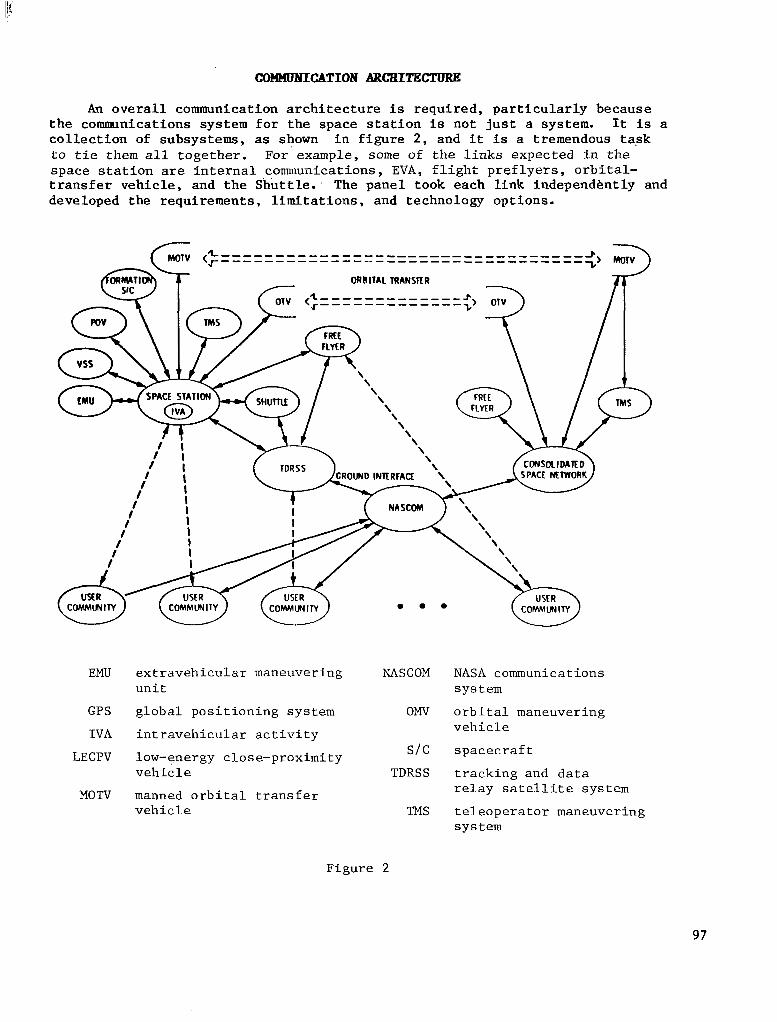
COMMUNICATION ARCHITECTURE
An o v e r a l l communication architecture is r e q u i r e d , p a r t i c u l a r l y b e c a u s e the communicat ions system for the space s ta t ion is n o t j u s t a system. It i s a c o l l e c t i o n of subsystems, as shown i n f i g u r e 2 , and i t is a tremendous task to t i e them a l l together. For example, some of t h e l i n k s e x p e c t e d i n t h e s p a c e s t a t i o n are in te rna l communica t ions , EVA, f l i g h t p r e f l y e r s , o r b i t a l - t r a n s f e r v e h i c l e , a n d t h e S h u t t l e . . The panel took each l ink independently and developed the requirements , l imitat ions, and technology opt ions.
ORBIIAL TRANSlIR
SPACE STATION
EMU extravehicular maneuvering u n i t
GPS glob-a1 posit ioning system
I V A i n t r a v e h i c u l a r a c t i v i t y
LECPV low-energy close-proximity v e h i c l e
M O W manned o r b i t a l t r a n s f e r v e h i c l e
NASCOM NASA communications System
OMV orb i ta l maneuver ing v e h i c l e
S I C s p a c e c r a f t
TDRSS t r ack ing and d a t a r e l a y s a t e l l i t e system
TMS te leoperator maneuvering sys t e m
F igure 2
97

INTRAVEEIIcITLbB (XMMJNICATIONS
The s u b j e c t of intravehicular communicat ions raises v e r y i n t e r e s t i n g a n d unusual requirements for communications (fig. 3 ) . Normally, a telephone could be used ins ide a v e h i c l e o r wires could be a t t a c h e d t o t h e man when he is i n h i s p r e s s u r e s u i t . The main ambition of communications on t h e s p a c e s t a t i o n i s f o r t h e 10- t o 12-man crew t o be a b l e t o move around i n the c losed con ta ine r w i thou t cons t r a in t s .
Among t h e l i m i t a t i o n s of wireless communications are the bulk and excess power requirements of RF systems. Even f ibe r op t i c cab le s and i n t e rmodu le connections are complex. Te lev is ion equipment requi res au tomat ions fea tures which are no t ye t ava i l ab le .
The technology options include short-range laser l i n k s i n l i e u of f i b e r o p t i c s f o r module t o module communications and antennas t o t h e o u t s i d e . I R b roadcas t ing has been used in a i rp lane cab ins and thea te rs as an augmentation for the deaf . Also needed are h i g h e r r e s o l u t i o n , h i g h s e n s i t i v i t y , s o l i d - s t a t e t r a n s f o r m e r s and te levis ion equipment .
BFQU I RFMENTS 1 WIRELESS CREW VOICE AND DATA COMMUNICATIO!iS FOR 10-12 CREWMEN I TRANSFER OF COMFUNICATION SIGNALS TO/FRON ANTENNAS (VERY WIDEBAND SIGNALS) I EXTENSIVE CLOSED-CI RCUIT TV, TELEPRESENCE SUPPORT
1 WIRELESS (R.F, - RADIO FREQUENCIES) 0 BULKY, EXCESS POWER (MANY BATTERIES)
0 COMPLEXITY OF CABLE AND FIBER OPTICS INTERMODULE CONNECTIONS 0 GROWTH (BUILD UP CHANGES ARE A CONCERN)
I LACK OF PROVEN AUTOMATED FEATURES @ LIMITED QUALITY OF STERE@ TV
I HARDLINE
I TV EQU IPRENT
@ PERFORKANCE LIMITATIONS OF LOW-COST SOLID-STATE DEVICES
01 OGY OPTIONS (TO OVERCOME LIMITATIONS) I SHORT-RANGE LASER LINKS (MODULE TO FIIODULE, ANTENNA TO FODULE INTERFACE) 0 IR BAND EXPLOITATION @ HIGH RESOLUTION, HIGH SENSITIVITY, AND SOLID-STATE TV COMPONENTS I TV EQU I PPlENT AUTO!.lATIOri, INCREASED INTELLIGENCE
LQuMENI @ IR FLOODED VOLURE AND LASER LINKS COULD REPLACE MOST SIGNAL AMI
CONTROL WIRIfiG
Figure 3
98
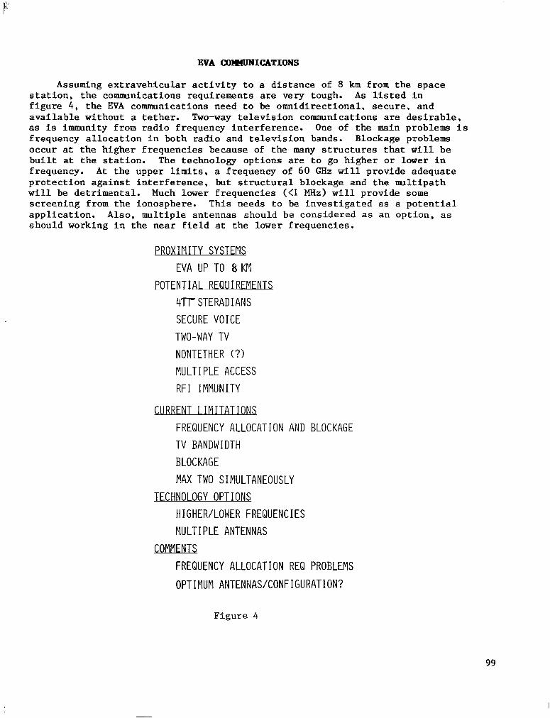
EVA 00"NICATIONS
Assuming e x t r a v e h i c u l a r a c t i v i t y t o a d i s t ance of 8 km from the space s t a t i o n , t h e communications requirements are very tough. As l i s t e d i n f i g u r e 4 , t h e EVA communications need t o be omnidi rec t iona l , secure , and ava i l ab le w i thou t a t e t h e r . Two-way television communications are d e s i r a b l e , as is immunity from radio frequency interference. One of t he main problems i s f r equency a l loca t ion i n bo th r ad io and t e l ev i s ion bands. Blockage problems occur a t the higher f requencies because of t he many s t r u c t u r e s t h a t w i l l be b u i l t a t t h e s t a t i o n . The technology options are t o go h i g h e r o r l o w e r i n frequency. A t the upper limits, a frequency of 60 GHz w i l l provide adequate p r o t e c t i o n a g a i n s t i n t e r f e r e n c e , b u t s t r u c t u r a l b l o c k a g e a n d t h e r m l t i p a t h w i l l be de t r imen ta l . Much lower frequencies (<1 MHz) w i l l provide some screening f rom the ionosphere. This needs to be i n v e s t i g a t e d as a p o t e n t i a l appl ica t ion . Also , mul t ip le an tennas should be cons idered as an op t ion , as should working i n t h e n e a r f i e l d a t the lower frequencies.
PROXIMITY SYSTFMS
EVA UP TO 8 KM POTENTIA1 RFQUI REPIFNTS
4 T STERADIAIJS
SECURE VOICE
TWO-WAY TV
NONTETHER (?> PlULT I PLE ACCESS
RFI IMMUNITY
CURRENT I I M I T A T I O N S
FREQUENCY ALLOCATION AND BLOCKAGE
TV BANDWIDTH
BLOCKAGE
MAX TWO SIMULTANEOUSLY
TECHNO1 OGY OPTIONS
HIGHER/LOWER FREQUENCIES
MULTIPLE ANTENNAS
COMMENTS FREQUENCY ALLOCATION REQ PROBLEMS
OPTIMUM ANTEN~~AS/CONFIGURATION?
Figure 4
99

EXTERNAL COMMUNICATIONS
Requi rements , l imi ta t ions , and technology op t ions for space s ta t ion e x t e r n a l communications ( including data, voice, and video) are l i s t e d i n f i g u r e 5. Data rates in the mult imegabi t range are needed which are j u s t ou ts ide the range of t h e TDRSS. Also needed are rmlt iple-frequency capabi l - i t y , s imu l t aneous ope ra t ions , ded ica t ed - l ink capab i l i t y , s ecu re and an t i j am c a p a b i l i t y , and rout ing and swi tch ing capabi l i ty . The two pr ime l imi ta t ions are an tenna p ro l i f e ra t ion and l i nk ava i l ab i l i t y . The Shu t t l e has ove r 20 antennas aboard and as many as 50 may be r equ i r ed on the space s ta t ion . Wi th the space s ta t ion conf igura t ion changes and the l ine of s igh t requi rement , l o c a t i n g 50 an tennas t o ope ra t e e f f ec t ive ly w i l l be d i f f i c u l t . L i n k a v a i l - a b i l i t y is not absolutely continuous. There is a gap over the Ind ian Ocean where the l ink may not be ava i l ab le . To accommodate these h igh da t a rates and ava i l ab i l i t y r equ i r emen t s , a dedicated TDRSS sa te l l i t e with follow-on access t o TDAS (Tracking and Data Acquisition System) would be h e l p f u l , i f i t could be afforded.
Some of the enabling technology options are to develop antennas that can handle mult iple f requencies and mult iple beams (e.g. , offset-beam techniques, phased a r r ays , o r va r i a t ions of these t echniques) . The use of millimeter waves (with 60 GHz as the carrier frequency) i s -already under s tudy to provide t h e l i n k c a p a b i l i t y f o r t h e h i g h d a t a rates.
One of t he p rob lems i n t h i s area i s t h a t a g r e a t d e a l of information i s ava i l ab le abou t t he t echno logy i n c l a s s i f ed fo rm and t h i s area needs to be explored. -
0 MULTIPLE DATA RATE (1 KBPS TO 7 1 GBPS) 0 MULTIPLE-FREQUENCY CAPABILITY 0 SIFlULTANEOUS OPERATIOiS 0 FibLTIPLE SPATIAL COVERAGE
0 SECURE ANTIJAM CAPABILITY 0 ROUTING AND SWITCHING CAPABILITY
0 DEDICATED-LIriK CAPABILITY
I M I T A T I W 0 DATA RATE CONSTRAINTS 0 LINK AVAILABILITY CONSTRAINTS 0 ANTEiJNA PROLIFERATION
0 #ULTIFR€QUENCY AND MULTIBEAM ANTEHNAS 0 HIGH DATA RATE SIGNAL PROCESSING/SWITCHING 0 HIGH DATA RATE BUFFERS 0 MM WAWOPTICAL LINK CAPABILITY
c.fhlwE 0 DEVELOPRENT OF COMFlUNICATION HANDLING STRATEGIES 0 DEVELOPMENT OF OPTICAL BASEBAND PROCESSING 0 OBTAIN DOD TECHNOLOGY STATUS
Figure 5
100

NBVIGATION, TRACKING, AND RANGING
Navigat ion, t racking, and ranging need completely c i rcular coverage c lose t o t h e s p a c e s t a t i o n to a d i s t a n c e of about 8 k i lometers , wi th var iab le range and range rate c a p a b i l i t y ( f i g . 6 ) . Although there are some accuracy problems (in genera l , the requi red accurac ies could be a t t a ined ) , r ange and ang le r e s o l u t i o n are actual ly the basic problem. Soft docking requires reducing the c los ing speeds t o a very low rate, and the use of millimeter waves (with F"/CW systems) would measure range down to abou t 5 f e e t . A t a r g e t i d e n t i f i c a t i o n system could be bui l t in to cooperat ive systems.
Enabling technology options include adaptive multibeam antennas, phased a r r a y , millimeter wave r a d a r , s o l i d - s t a t e l i d a r a n d i n t e g r a t e d COMM/NAV o r FM/cW systems.
POTFNT I A I RFQU I RFRFNTS 0 MULTIPLE TARGET DISCRIMINATION 0 4 n ' STERADIAN COVERAGE @ VARIAELE RANGE AND RANGE RATES CAPABILITY 0 SOFT DOCKING
EXTERNAL SYSTEMS HAND-OVER CAPABILITY 0 AUTOMATED OPERAT I OMS 0 TARGET IDENTIFICATICN CAPABILITY
CURRFNT I IMITATIONS 0 NEAR-RANGE LIF i ITATIOt l 0 LOW VELOCITY !XTERMINATION TECHNIQUES 0 ABSENCE OF TARGET ATTITUDE INFORrlATION 0 LACK OF 4 Tf STERADIAN COVERAGE
FWARl ING TFCHNOI OGY 0PTIO:iS 0 ADAPTIVE MULTIBEAM AfiD BEAM FORMIPIG ANTENNAS
1 INTEGRATED COKfWlAV SYSTEM APPROACH 0 rm RADAR/SOLID-STATE LIDAR
OPlMENTS 0 FREQUENCY ALLOCATION DETERMINATION ( R F I J BANDWIDTH, ETC, 1 8 ACCURATE MUTUAL COUPLING MODELING 0 ASSUME AVAILABIL ITY OF GLOBAL POSITIONING SYSTEF
Figure 6
101
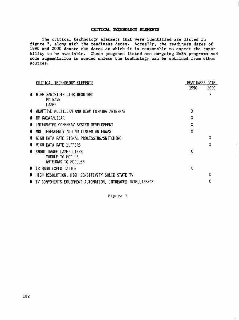
The c r i t i ca l technology elements that were i d e n t i f i e d are l i s t e d i n f i g u r e 7, a long wi th the readiness da tes . Actua l ly , the readiness da tes of 1990 and 2000 denote the da tes at which i t is reasonable to expec t the capa- b i l i t y t o be avai lable . These programs l is ted are on-going NASA programs and some augmentation is needed unless the technology can be obtained f rom other sources.
0 HIGH BANDWIDTH LIiJK REQUIRED EN WAVE LASER
0 ADAPTIVE MULTIbEAM AND BEAN FORFlING ANTENNAS # MM RADAR/LIDAR 0 INTEGRATED COMVNAV SYSTEM DEVELOPMENT 0 MULTIFREQUENCY AND MULTIBEAM AHTENiJAS 0 HIGH DATA RATE SIGNAL PROCESSING/SWITCHING 0 HIGH ljATA RATE BUFFERS 0 SHORT RAiJGE LASER LINKS
MODULE TO FiODULE AiITEiWAS TO MODULES
0 IR BAilD EXFLOITATIOli 0 HIGH RESOLCTION, HIGH SEiiSITIVITY SOLID STATE TV 0 TV COFIPONENTS EQUIPMENT ALTOMATIOIJ, INCREASED INTELLIGENCE
READ I NESS DATE 1990 2000
X
X X X X
X X
X
x x X
F i g u r e 7
102

1'
BASELINE CRITICAL SPACE =TION COM4UNICLLTION LINE DEVELOPMENT 1-
To summarize the industry recommendat ions, basel ine c r i t i ca l space s t a t i o n communfcation l i n k development items are l i s t e d i n f i g u r e 8 and ranked by p r io r i ty . The re w a s no d i f f i c u l t y i n r a n k i n g t h e items r e l a t i v e t o e a c h o t h e r i n a grouping. The main problem a r o s e i n a t t e m p t i n g t o make a n o v e r a l l p r i o r i t i z a t i o n , p r i m a r i l y b e c a u s e a l l of t hese items are rea l ly impor tan t and i t is d i f f i c u l t t o assess them c o l l e c t i v e l y .
The p a n e l f e l t t h a t i t was v e r y i m p o r t a n t t o e l i m i n a t e t h e p r o l i f e r a t i o n of antennas, which could be done by combining funct ions into one e lement i f poss ib l e .
PRIORITIES
ANTENHA TECHNOLOGY DEVELOPMENT 4 DISTRIBUTED MULTIFUIJCTIOidAL/MULTIFREQUENCY ANTENNAS/COMPONENTS @ MM RADAR ANTENNAS/HYBRID COMPONENTS a 4n STERADIA~~ INTEGRATED ARRAY SYSTEM
RF COMPOIJE[JT/SUBSYSTEPl DEVELOPMENT @ HIGH TIM-BANDWIDTH HIGH POWER SOLID STATE COIPONENTS @ HIGH POWEWHIGH RELIAUILITY LOW COST TWT'S @ LOk' NOISE NONCRYOGENIC AMPLIFIERS @ LOW CGST FREQCENCY SYNTHESIZERS @ UAIiPACK FINIATURIZATION
@ ALGORITHM APPLICATION TO CIRCUIT DEVELOPflENT I IiISTRUMENTATION ACCURACY AND VERIFICATION TECHMOLOGY 0 UPIDOHN FREOUEKY CONVERSIOE4 AND AGILE BAND PASS FILTERS
INTEGRATED COP!M/NAV DEMLOPYENT
OPT I CAL COhPONENTS AND SUBSYSTEMS @ SPACE QUALIFICATION @ POINTING AND ACQUISITION, AND TRACKING THROUGH BLOCKAGE
RELAT IM OVERALL
3 5 2 4 1 1
4 1 3 5 3 2 6
2 3 1
1 2
2
F i g u r e 3
103

FO”ON CRITICAL SPACE STATION COMMUNICATION LINK DEVELOPHENT ITKIS
Four major follow-on cr i t ical communication link development items were i d e n t i f i e d : v i d e o , RF component/subsystem development, signal processing and o p t i c a l components, and subsystems. These items are l i s t e d i n f i g u r e 9 a long w i t h t h e c r i t i c a l problem areas f o r each.
The in tegra ted communica t ions-naviga t ion ident i f ica t ion ( I C N I t ype ) technology is des igned for tact ical systems and consis ts of an a lgori thm t o produce a composite wave form to per form a l l these func t ions . Some of t h e techniques of this concept could be a p p l i e d t o t h e s e cr i t ical communication needs.
VIDEO 0 HIGH RESOLUTION, HIGH SENSITIVITY SOLID STATE TV 0 TV EQUIPMEAT AUTOMATIObl AND INCREASED INTELLIGENCE
AUTO FOCUS AUTO TRACK
RF COMPONFiiT/SUBSYSTFM DEVFl O P ~ ~ 0 HIGH BANDWIDTH L I N K (F:K WAVE)
HIGH POWER/tIIGtl RELIABIL ITY LOW-COST TRAVELLING WAVE TUBE HIGH PO’HER/HIGH R E L I W I L I T Y LOW COST SOLIB STATE l20/60 GHZ ADAPTIVE BEAM FORMING
w 0 HIGH DATA RATE SIGNAL PROCESSING/SWITCHING
FOCAL PLANE TECHNOLOGY AGILE BANDPASS FILTERING
0 HIGH DATA RATE BUFFER 0 I C N I 0 ELECTRO-OPTICAL
TS AND SUBSYST€MS 0 HIGH BANDWIDTH L INK
POINTIIJG/TRACKItJG/ACQUISITION HIGH POWER
Figure 9
104
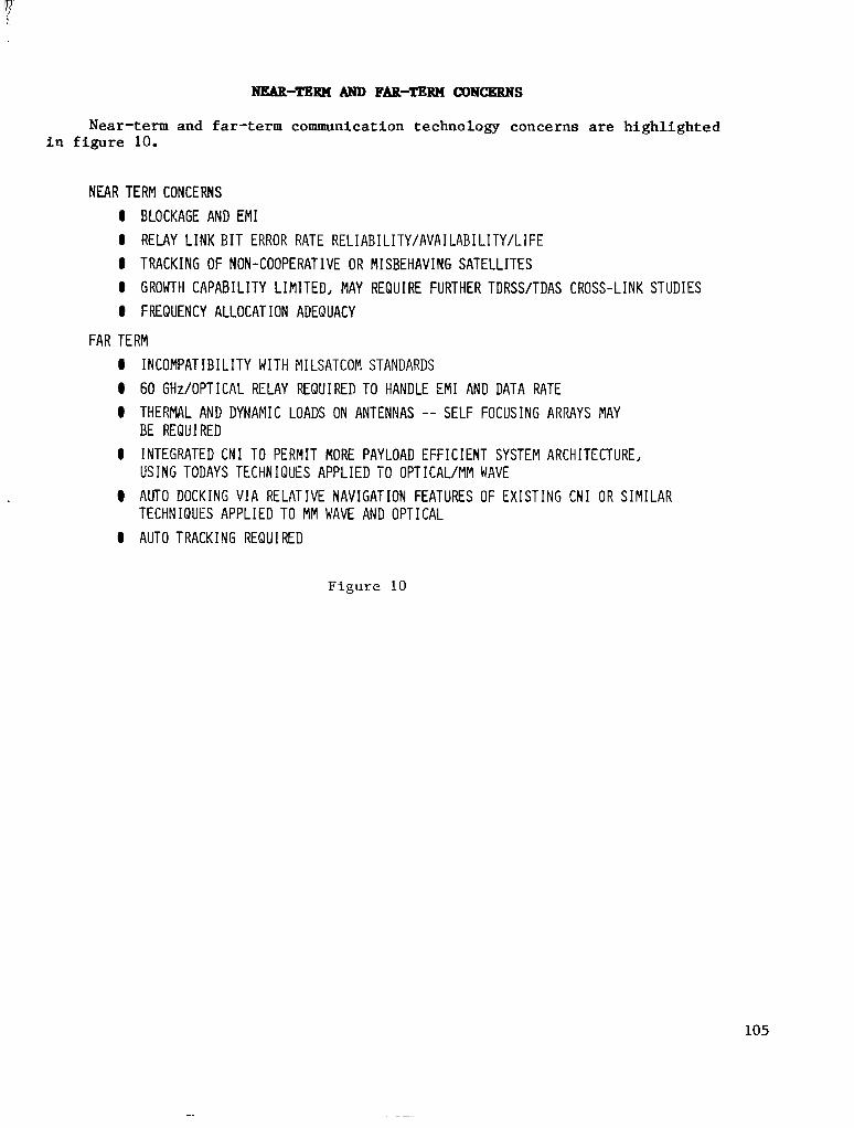
Near-term and far-term communication technology concerns are highlighted in figure 10.
NEAR TERM CONCERNS 0 BLOCKAGE AND EM1 0 RELAY L I N K B I T ERROR RATE RELIABILITY/AVAILABILITY/LIFE 8 TRACKING OF NON-COOPERATIVE OR MISBEHAVING SATELLITES 0 GROWTH CAPABILITY LIMITED, MAY REQUIRE FURTHER TDRSS/TDAS CROSS-LINK STUDIES 0 FREQUENCY ALLOCATION ADEQUACY
FAR TERM 0 INCOMPATIBILITY WITH MILSATCOM STANDARDS 0 60 GHzIOPTICAL RELAY REQUIRED TO HANDLE EM1 AND DATA RATE 8 THERMAL AND DYNAMIC LOADS ON ANTENNAS -- SELF FOCUSING ARRAYS MAY
BE REQUIRED 0 INTEGRATED CNI TO PERMIT MORE PAYLOAD EFFICIENT SYSTEM ARCHITECTURE,
USING TODAYS TECHNIQUES APPLIED TO OPTICAL/MM WAVE @ AUTO DOCKING VIA RELATIVE NAVIGATION FEATURES OF EXISTING CNI O R SIMILAR
0 AUTO TRACKING REQUIRED TECHNIQUES APPLIED TO MM WAVE AND OPTICAL
Figure 10
105

INDUSTRY ASSES!3lENT OF CRITICAL SPACJI STATION a"UNICATI0NS TECENOLWIES
The cr€tical space s ta t ion communicat ions technologies of f i g u r e s 3 through 6 were as ses sed by the panel and are l i s t e d i n f i g u r e 11 i n a n o r d e r r e p r e s e n t i n g a good compromise of opinion.
Consider ing the requirements for high data rates a n d t e l e v i s i o n and communications coverage, circular coverage even out to 8 km w i l l be d i f f i - c u l t due to the blockage problems. Even increas ing the f requency to cover the television bandwidth puts the system on t h e f r i n g e o f p o t e n t i a l b l o c k i n g problems. The VHF band did not provide RFI pro tec t ion , bu t i t was a good compromise between da ta rates and blockage. However, the VHF is no t ava i l - a b l e , so a d d i t i o n a l work mst be done t o f i n d a sys tem tha t w i l l meet a l l t h e requirements.
I n t h e area of high power, TWT's are not dead, i n s p i t e of a l l t h e work on so l id-s ta te devices . Sol id-s ta te devices have a r e l i a b i l i t y of 7 t o 10 y e a r s ( g r e a t e r t h a n t h e r e l i a b i l i t y of TWT's), but TWT's can be replaced and they provide more power and are more e f f i c i e n t ( t h r e e times t h a t of s o l i d state).
The millimeter band (about 60 GHz seems t o be optimum fo r eve ry th ing ) i s a good band. It is f r e e from immunity and i s a t the approximate peak of t h e l i n k budget curves. It could be improved by technology development to get good performance a t 120 GHz (the next harmonic band of oxygen a b s o r p t i o n ) , since performance is p ropor t iona l t o t he squa re of the f requency ( for f ixed an tenna s izes and cons tan t losses) .
A wel l -d is t r ibu ted rml t i func t iona l an tenna sys tem needs to be developed and the requirement for miniatur izat ion i s ser ious because the size and weight c o n s t r a i n t s are s o t i g h t .
0 4l? STERADIAN INTEGRATED ANTENNA ARRAY SYSTEM
0 FLIGHT QUALIFIED OPTICAL COMPONENTS AND SUBSYSTEPS
0 HIGH POWEWHIGH RELIABILITY LOW COST SPACE TWTS
0 M I L L I E T E R WAVE RADAR NJTENNAS/HYBRID COMPONENTS
0 DISTRIBUTED MULTIFUl~CTIONAL/MULTIFREQUEMCY ANTENNAS/COMPONENTS
0 MANPACK MINIATURIZATION OF RF COMPO?EiT/SUBSYSTEMS
F i g u r e 11
106

FLIGElT TEST REQUzBEHeNTS
Requirements for communications hardware f l ight tests are d i f f i c u l t to d e f i n e a t t h i s time ( f i g . 12). However, two experiments on t h e S h u t t l e were i d e n t i f i e d t o i n v e s t i g a t e some of t h e areas of concern. One experiment would u s e a r a d i o r e c e i v e r on the Shut t le to record b roadcas ts f rom Ear th to check the R F I i n t h e lower frequency bands a t tha t a l t i t ude and de t e rmine t he l eak - a g e t o t h e t o p of the ionosphere. The o t h e r is an op t i ca l expe r imen t t o measu re t he g l in t and pa r t i cu la t e s ca t t e r ing e f f ec t s .
0 EXAM INL THE RF I ENVIRONMENT BY MONITORING LFJ FFJ HF BROADCAST STATIONS FROM SHUTTLE.
0 EXAMINE THE GLINT AND PARTICULATE SCATTERING EFFECTS FROM THE SHUTTLE TO DEFINFr POTENTIAL LASER COMMUNICATIONS PROELEMS
0 HARDWARE FLIGHT TEST REQU IREMFrNTS DIFFICULT TO DEFINE AT THIS TIME
Figure 12
107

REOBQIENDATIONS
Recommendations made by the communications panel are l i s t e d i n f i g u r e 13. NASA should form a space station communications working group comprised of r e p r e s e n t a t i v e s f r o m i n d u s t r y , u n i v e r s i t y , DOD, and NASA. The working group should in te r face wi th o ther working groups and coord ina te ou tputs f rom these groups. A s i n almost any project , funding is inadequate and may have an adverse impact on t h e o p e r a t i o n a l r e a d i n e s s of t h e s p a c e s t a t i o n program. More s p e c i f i c i t y is requ i r ed on the space s ta t ion communica t ion a rch i tec ture . Poss ib ly a series of a rch i t ec tu re s shou ld be developed: a very near term, a midterm and a f a r term. The pane l a l so s t rong ly recommended a follow-on workshop a f t e r t h e r e s u l t s from the cu r ren t workshop and data from ongoing studies have been assimilated and assessed. The impact of NASA programs on space s t a t i o n a c t i v i t i e s i n i n d u s t r y and DOD needs to be assessed.
@ FORM NASA/INDUSTRY/L!NIVERSITY/DOD SPACE STATION COMMUNICATIONS WORKING GROUP
@ COORDINATE OUTPUTS OF OTHER WORKING GROUPS
@ FUdDIHG IN T H I S AREA IS INADEQUATE AND ADVERSELY IPlPACTS THE OPERAlIONAL READINESS OF THE SPACE STATICN PRCGEAN
@ flOE SPECIFICITY REQUIRED 01i SPACE STATION ARCHITECTUM
@ FOLLCW-0;: SPACE STATIO:: KORiKSHOP AFTER DATA FROM STUDIES AiW I ~ I T I R L WORXSHOP HAVE BEEN PtSSESSEC
@ ,4SSESS IMPACl OF M S A PkOGRAW OFFICES' C0MF:UNICATION A C T I V I T I E S O?I THE SPACE STAT IOh'
Figure 13
108
David Purdy General Electric Company
Philadelphia, Pennsylvania
Space Station Technology Workshop Williamsburg, Virginia
March 28-31, 1983
109
I

INTRODUCTION
Structures, materials, and mechanisms is one of the older technologies in the aerospace business. The Structures, Materials, and Mechanisms Panel was divided into the four basic categories that fit the overall responsibilities of the panel, as shown in figure 1.
0 M A T E R I A L S
0 MECHAM ISMS
0 STRUCTURAL DESIGN
0 ArlALYS I S
Figure 1
110

P.Y. 1983 MATERIkLS AND STBUCTURES BUDGET
There is already a good-sized structures and materials program within NASA, spending about $14.7 million a year in space-related structures and materials activities, with about $3.7 million designated specifically for space station type activities. The budget, by category, is shown in figure 2 for the five major structures and materials thrusts.
THRUSTS (THOUSANDS OF DOLLARS) SPLIT BY CATEGORY
BASIC -
VATER I ALS SC I ENCE 2520 SPACE DURABLE MATERIALS 1225
i ADVANCED TPS 200 I
ADVANCED SPACE STRUCTURES 300
ANALYSIS AND SYNTHESIS 100 -
TOTAL 4345
STS -
- 170
2755
1100 750 -
4075
F i g u r e 2
SPACECRAFT
- 553 -
:982 209 -
2535
SPACE PLATFOM TOTAL ”
- 2520
1015 2763 - 3 5 5
3750 14/05
111
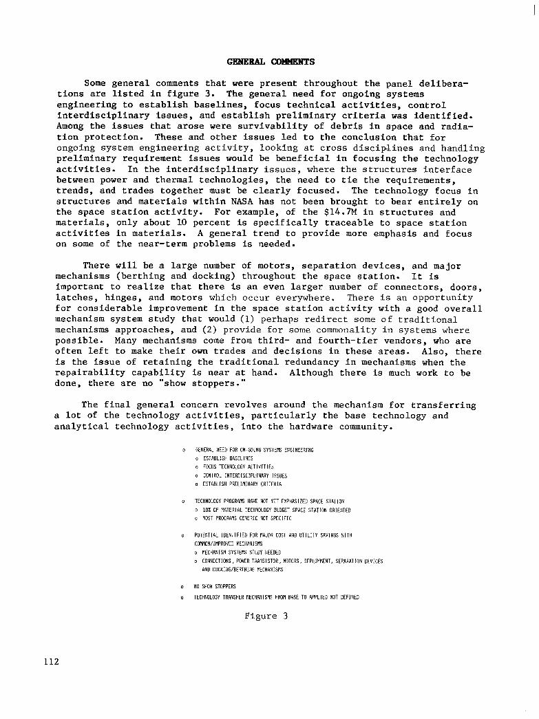
Some gene ra l comments t h a t were present th roughout the pane l de l ibera- t i o n s are l i s t e d i n f i g u r e 3. The gene ra l need for ongoing systems e n g i n e e r i n g t o e s t a b l i s h b a s e l i n e s , f o c u s t e c h n i c a l a c t i v i t i e s , c o n t r o l i n t e r d i s c i p l i n a r y I s s u e s , and e s t a b l i s h p r e l i m i n a r y cr i ter ia was i d e n t i f i e d . Among t h e i s s u e s t h a t a r o s e were s u r v i v a b i l i t y of d e b r i s i n s p a c e and radia- t i on p ro t ec t ion . These and o the r i s sues l ed t o t he conc lus ion t ha t fo r ongoing sys tem engineer ing ac t iv i ty , looking a t c r o s s d i s c i p l i n e s and handling prel iminary requirement issues would be bene f i c i a l i n focus ing t he t echno logy a c t i v i t i e s . I n t h e i n t e r d i s c i p l i n a r y i s s u e s , w h e r e t h e s t r u c t u r e s i n t e r f a c e between power and thermal technologies , the need to t i e the requirements , t r ends , and t r ades t oge the r must be c lear ly focused . The technology focus in s t r u c t u r e s and materials wi th in NASA has not been brought to bear ent i re ly on t h e s p a c e s t a t i o n a c t i v i t y . F o r example, of t he $14.7M i n s t r u c t u r e s and materials, only about 10 percent is s p e c i f i c a l l y t r a c e a b l e t o s p a c e s t a t i o n a c t i v i t i e s i n materials. A genera l t rend to p rovide more emphasis and focus on some of the near-term problems is needed.
There w i l l be a l a r g e number of motors , separa t ion devices , and major mechanisms (be r th ing and docking) throughout the space s t a t i o n . It is i m p o r t a n t t o r e a l i z e t h a t t h e r e is an even larger number of connectors , doors , l a t ches , h inges , and motors which occur everywhere. There i s an opportuni ty fo r cons ide rab le improvement i n t h e s p a c e s t a t i o n a c t i v i t y w i t h a good o v e r a l l mechanism system study that would (1) pe rhaps r ed i r ec t some o f t r a d i t i o n a l mechanisms approaches, and ( 2 ) p rov ide fo r some commonality in systems where poss ib l e . Many mechanisms come from th i rd - and four th- t ie r vendors , who are o f t e n l e f t t o make t h e i r own t r ades and d e c i s i o n s i n t h e s e a r e a s . Also, t h e r e is t h e i s s u e of r e t a i n i n g t h e t r a d i t i o n a l r e d u n d a n c y i n mechanisms when t h e r e p a i r a b i l i t y c a p a b i l i t y is near a t hand. Although there is much work t o be done, there are no "show s toppers . "
The f ina l genera l concern revolves a round the mechanism f o r t r a n s f e r r i n g a l o t of t he t echno logy ac t iv i t i e s , pa r t i cu la r ly t he base t echno logy and a n a l y t i c a l t e c h n o l o g y a c t i v i t i e s , i n t o t h e h a r d w a r e community.
o GENERAL l E E D FOR ON-GOING SYSTEMS ENGINEERING o ESTABLISH BASELINES o FOCUS TECHNOLOGY A C T I V I T I E S
o CONTROL I N T E R D I S C I P L I N A R Y I S S i E S o ESTABLISH PRELI f i INRRY CRITERIA
o TECHNOLOGY PROGRAMS HAVE ROT YET EMPHASIZED SPACE STATION
o 10% OF RATERIAL TECHNOLOGY BUDGET SPACE STATION ORlEf lTED o MOST PROGRAMS GENERIC NOT S P E C I F I C
o POTENTIAL IDENTIF IED FOR MAJOR COST A1D U T I L I T Y S A V I N G S !.IITH COMMON/IMPROVED MECHAlllSMS o MECHANISM SYSTEllS STUDY llEEDED o CONNECTIONS, POWER TRAtlSISTOR, MOTORS, DEPLOYRENT, SEPARATION DEVICES
AND DOCKI;IG/BERTHIliG NECHANIS!IS
o NO SHOd STOPPERS
o TECHNOLOGY TRANSFER RECHAHISMS FROM BASE TO APPLIED BOT DEFINED
Figure 3
112

INTERDISCIPLINARY ISSUES
The panel spent considerable time working on the interdisciplinary issues with representatives from the other panels. The key interdisciplinary issues between structures and the power, thermal, and controls technologies are listed in figure 4. The structures-power issue involved systems engineering in the solar array development to ensure that all the structural, weight, and trade issues were addressed in the solar array concept selection. In the thermal area, the principal concern involved the need for a deployable radiator, which potentially would rotate. Structurally, the radiator could be made stiff enough. Many materials problems would be solved; rotation would keep the coatings out of the Sun and eliminate radiator degradation. There were "no major issues" in the structures-controls interface.
POWER
o STRUCTUkAL ENGINEERIIG SUPPORT REQUIRED IN SOLAR ARRAY DEVELOPMEriT
THERMAL
o STRUCTURES PAIEL CONCERIiED ABOUT DEPLOYABLE ROTATING RADIATOR
CONTROLS
o NO MAJOR ISSUES; 1IiTERDISCIPLI;JARY PANEL IN PLACE
CONCLUS I ON
o SYSTEM ENGIt*lEERING RELIUIRED
F i g u r e 4
113
I II
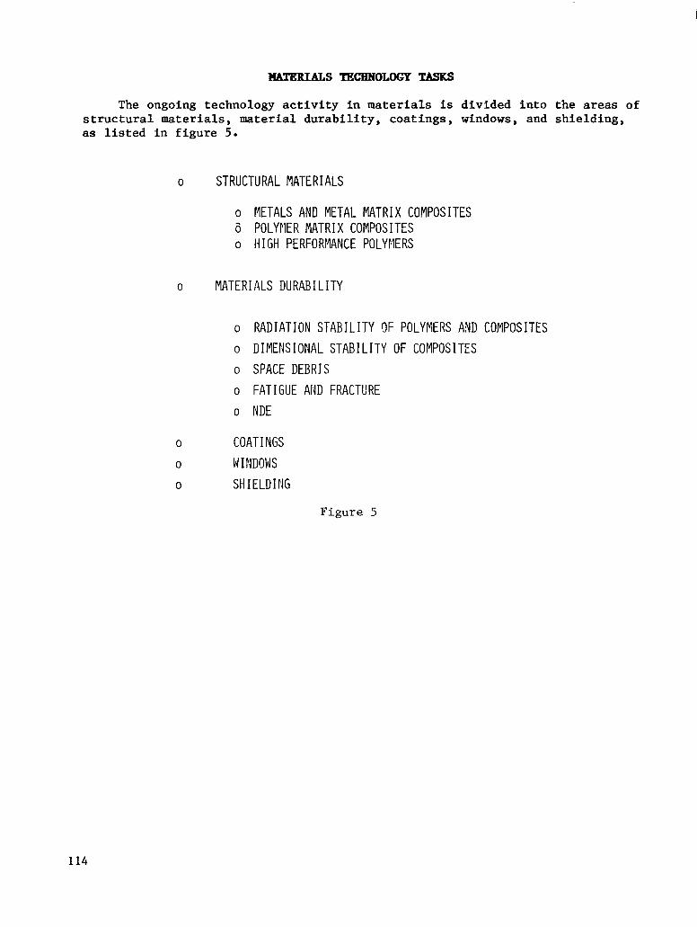
The ongoing technology activity in materials is divided into the areas of structural materials, material durability, coatings, windows, and shielding, as listed in figure 5.
0 STRUCTURAL MATERIALS
o METALS AND METAL MATRIX COMPOSITES 6 POLYrlER MATRIX COMPOSITES o HIGH PERFORMANCE POLYMERS
0 MATERIALS DURABILITY
o RADIATION STABIL ITY C)F POLYMERS A I D COMPOSITES o D I MENS I ONAL STAB I L I TY OF COMPOS I TES
o SPACE DEBRIS
o FATIGUE AND FRACTURE
o NDE
COAT I NGS
WINDOWS SH I ELD I NG
Figure 5
114
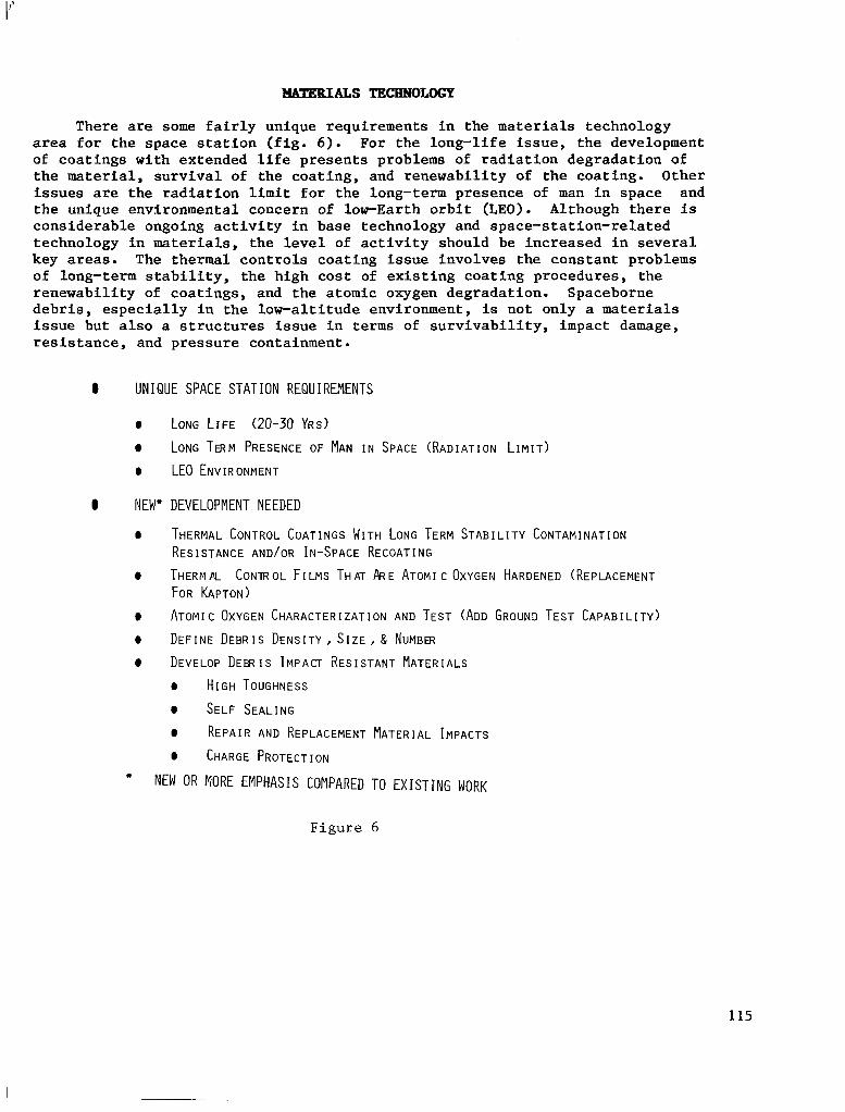
There are some fairly unique requirements in the materials technology area for the space station (fig. 6 ) . For the long-life issue, the development of coatings with extended life presents problems of radiation degradation of the material, survival of the coating, and renewability of the coating. Other issues are the radiation limit for the long-term presence of man in space and the unique environmental concern of lorEarth orbit (LEO). Although there is considerable ongoing activity in base technology and space-station-related technology in materials, the level of activity should be increased in several key areas. The thermal controls coating issue involves the constant problems of long-term stability, the high cost of existing coating procedures, the renewability of coatings, and the atomic oxygen degradation. Spaceborne debris, especially in the low-altitude environment, is not only a materials issue but also a structures issue in terms of survivability, impact damage, resistance, and pressure containment.
0 UNIQUE SPACE STATION REQUIREMENTS
0 LONG LIFE (20-30 YRS) 0 LONG TERM PRESENCE OF MAN IN SPACE (RADIATION LIMIT) 0 LEO ENVIRONMENT
0 NEW* DEVELOPMENT NEEDED
0 THERMAL CONTROL COATINGS WITH LONG TERM STABILITY CONTAMINATION RES I STANCE AND/OR IN-SPACE RECOAT ING
FOR KAPTON) 0 THERMPL CONTROL FILMS THAT ARE ATOMI c OXYGEN HARDENED (REPLACEMENT
0 ATOMIC OXYGEN CHARACTERIZATION AND TEST (ADD GROUND TEST CAPABILITY) 0 DEFINE DEBRIS DENSITY, SIZE, 8 NUMBER 0 DEVELOP DEBRIS IMPACT RESISTANT MATERIALS
0 HIGH TOUGHNESS 0 SELF SEALING 0 REPAIR AND REPLACEMENT MATERIAL IMPACTS
0 CHARGE PROTECTION
* NEW OR MORE EMPHASIS COMPARED TO EXISTING WORK
Figure 6
115
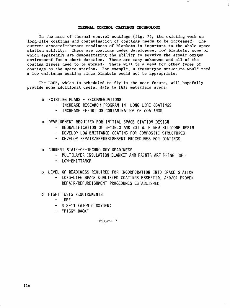
TBERnBL CONTROL COLLTINGS TECHNOLOGY
In the area of thermal control coatings (fig. 7) , the existing work on long-life coatings and contamination of coatings needs to be increased. The current state-of-the-art readiness of blankets is important to the whole space station activity. There are coatings under development for blankets, some of which apparently are demonstrating the ability to survive the atomic oxygen environment for a short duration. These are many unknowns and all of the coating issues need to be worked. There will be a need for other types of coatings on the space station. For example, a truss-type structure would need a low emittance coating since blankets would not be appropriate.
The LDEF, which is scheduled to fly in the near future, will hopefully provide some additional useful data in this materials arena.
o E X I S T I N G P L A N S - RECOMMENDATIONS - INCREASE RESEARCH PROGRAM I N L O N G - L I F E C O A T I N G S - INCREASE EFFORT ON CONTAMINATION OF COATINGS
o DEVELOPMENT REQUIRED FOR I N I T I A L SPACE STATION DESIGN - R E Q U A L I F I C A T I O N OF S-13GLO AND ZOT WITH NEW S I L I C O N E R E S I N - DEVELOP LOW-EMITTANCE COATING FOR COMPOS1 TE STRUCTURES - DEVELOP REPAIR/REFURBISHMENT PROCEDURES FOR COATINGS
0 CURRENT STATE-OF-TECHNOLOGY READINESS - MULTILAYER INSULATION BLANKET AND PAINTS ARE BEING USED - LOW-EM1 TTANCE
0 LEVEL OF READINESS REQUIRED FOR INCORPORATION INTO SPACE STATION - LONG-LI FE SPACE QUAL1 FIED COATINGS ESSENTIAL AND/OR PROVEN
REPAIR/REFURBISHMENT PROCEDURES ESTABLISHED
o FIGHT TESTS REQUIREMENTS - LDEF - STS-11 (ATOMIC OXYGEN) - "PIGGY BACK"
Figure 7
116

SHIELDING TECHNOLOGY
Shielding is an issue for the materials community and the principal concern is the requirements. Some of the issues on which the requirements will be based are listed in figure 8. The radiation problem,and hence the shielding requirement, is orbit dependent, mission dependent, and time dependent.
0 RADIATION EXPOSURE WILL L IMIT THE MAXIMUM TIFilE AN ASTRONAUT CAN SPEND PER YEAR AT SPACE STATION
0 MAJOR SOLAR PARTICLE EVENTS POSE A SIGNIFICANT HEALTH HAZARD TO ASTRONAUTS
0 STORM SHELTERS REQUIRED
0 EARLY WARNING SYSTEtl NECESSARY
o REAL TIME RADIATION MONITOR REQUIRED TO DETECT CHANGE I N INTEGRATED TRAPPED RADIATION
Figure 8
117
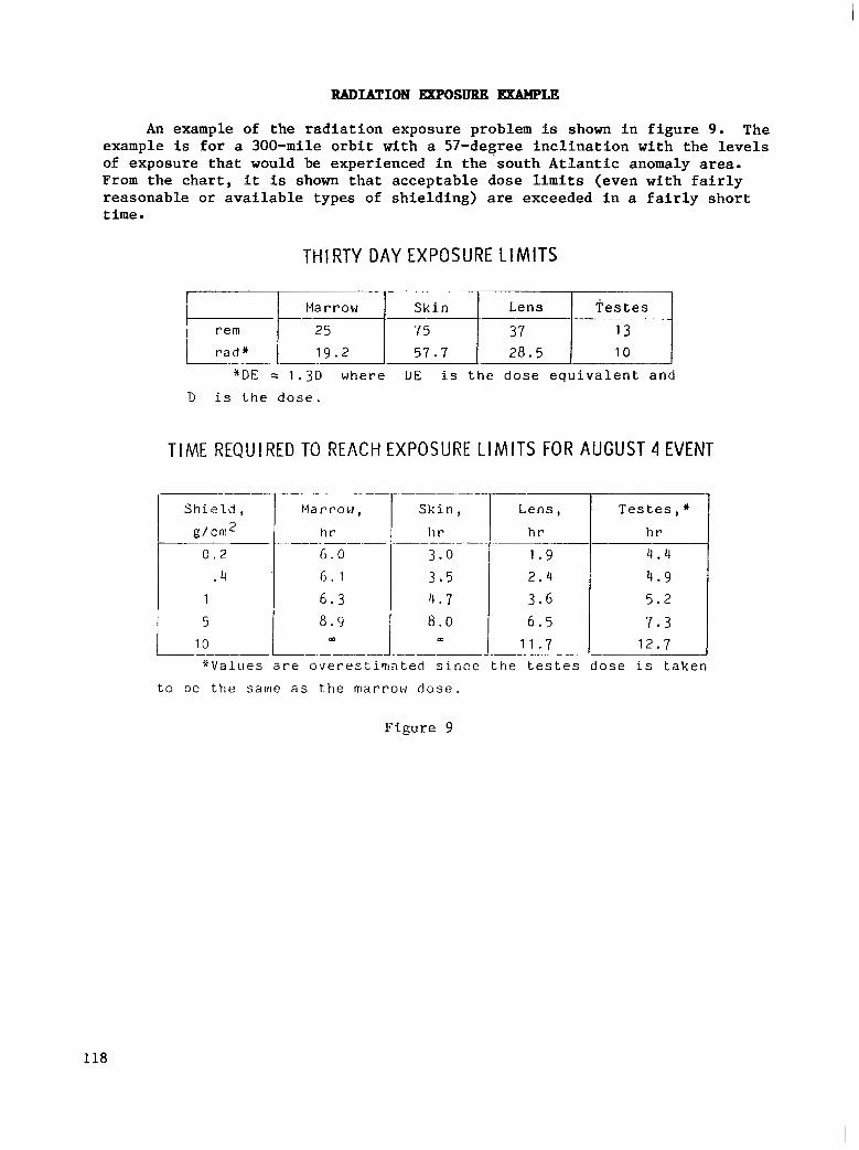
RADIATION EXPOSURE -LE
An example of the radiation exposure problem is shown in figure 9 . The example is for a 300-mile orbit with a 57-degree inclination with the levels of exposure that would be experienced in the south Atlantic anomaly area. From the chart, it is shown that acceptable dose limits (even with fairly reasonable or available types of shielding) are exceeded in a fairly short time .
THIRTY DAY EXPOSURE LIMITS
-___.
1 9 . 2 5 7 . 7 28.5 10
* D E = 1 . 3 D where DE is t h e d o s e e q u i v a l e n t a n d "
D i s t h e d o s e .
TIME REQUIRED TO REACH EXPOSURE L I M I T S FOR AUGUST 4 EVENT
Mar rou ,
h r
6 . 0 6 . 1
6 . 3 8 . 9
W
""
S k i n ,
h r
3.0
3 . 5 14 . 7 8 . 0
- - " - - -.
m
7
-
- " V a l u e s a r e o v e r e s t i m a t e d s i . nce t h e t e s t e s d o s e is t a k e n
Lens , T e s t e s , * h r
1 . 9
h r
7 . 3 6 . 5 5 . 2 3 . 6 4 . 9 2 . 4
4 . 4
1 1 . 7 12 .7
" -
-
t o be the same a s t h e marrow d o s e .
Figure 9
118
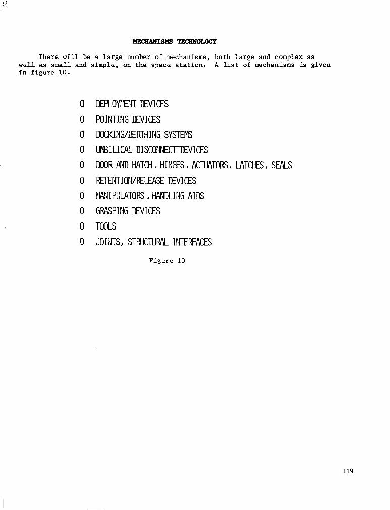
M E C E A N I S S TEcHNoLoGp
There will be a large number of mechanisms, both large and complex as well as small and in figure 10.
0 0 a 0 0 0 0
0 0 c)
simple; on the space station.. A list of mechanisms is given
DEPLOyI'EtcT DEVICES POINTING DEVICES DOCKItWBERTH I TJG SYSTEMS UF"BIL1CAL DISCOMJECTDNICES DOOR MJD HATCH I HINGES ACTUATORS I LATCHES SEALS
R€IENTIOWRELEASE DEVICES M!IIPIILATORS I M D L I H G AIDS
GRASPING DEVICES TOOLS
JOIISTS, STRUCTUW I!sIERFAcES
F i g u r e 10
119

MECHANISM REQUIREMENTS
The requirements for the mechanisms on the space station are the same as for any spacecraft. These requirements include long life, predictable life, high reliability, variability, precision of function, and low cost, as shown in figure 11.
0 LONG LIFE, PREDICTABLE LIFE
0 HIGH RELIABILITY
0 VARIABILITY OF FUMCTION
0 PRECISION OF FUNCTION
0 LOW PROGRAM COSTS
Figure 11
120

The mechanical technology program encompasses three areas: mechanical elements, mechanical systems, and analysis design. Each of the activities and associated plans listed in figure 12 was discussed. There was a major concern over using robotics to perform a mechanical function, but it appears that there 16 potential for effective use of mechanisms managed by sensing systems and controlled through a computer.
o MFCHANICAI FI FMFNTS - SEALS - LUB R I CANTS - POWER TRANSPlISSION (ROLLER DRIVE) - LATCHES/CO!4;4ECTORS/UMB I L I CALS - SMART MECHANISM COtJCEPTS
o MFCHAN I CAI SYSTFrIS - DEPLOYMENT/ASSEMBLY DEVICES - REMOTE MANIPULATOR (SPACE CRANE) - DOCK1 tJG/BERTH I FIG
0 A- - KINEF1ATICS/RELI,4BILITY ANALYSIS
F i g u r e 1 2
121

GKNEEAL UXQ4ENT ON HECEANISH TECBNOLOGP
The principal comment relative to mechanism technology was that it was unfunded (fig. 13). The panel concluded that there was a potential for real savings (in terms of cost and usability of the space station) which would go beyond just doing some mechanical technology and developing better mechanisms, as well as an opportunity to develop new approaches and commonality among the many mechanisms. This would make a significant impact on this activity. A systems level study of the use of mechanisms (types, power required, type of force dispersed) should be undertaken to define recommendations for what should be developed and how.
o ZERO FUNDING FOR MECHANISMS I S NOT APPROPRIATE o VAST QUAYTITY OF MECHANISMS OH SPACE STATIOtJ OFFER PO
FOR STAFiDARDIZATIO:,I AND NEW APPROACHES TENT I AL
o OVERALL SYSTEMS STUDY NEEDED, FOLLOWED BY TECHNOLOGY PROGRAMS
F i g u r e 13
122
The microprocessor gives a new dimension to mechanism control and will drastically alter design philosophy (fig. 14). The smart mechanism provides the opportunity for potentially decreasing workload and taking advantage of the kind of capability that is coming on line in terms of sensors and micro- computer control. A wide variety of functions can be performed, including docking, attenuators, actuators, sensing, and pointing.
o MICROPROCESSORS GIVE NEU DIMENSIOl TO MECHAiJISM CONTROL, N I L L DRASTICALLY ALTER DESIGN PHILOSOPHY WITH REGARD TO:
- REDUNDANCY, FAULT SEiJSING, FAILURE TOLERANCE - VARIABILITY OF FUIdCTION - PRECISION OF FUHCTION - PlECHAN I CAL DESIGN
o THE SPACE STATION WILL i3EED SMART MECHANISMS TO ACCOMMODATE: - WIDELY VARIED PERFORMANCE REQUIREMErlTS, SUCH AS FOR DOCKING
ATTENUATORS/ACTUATORS - PRECISION IN SE4SING/POINTING ACTUATORS - REQUIREMEi,lTS FOR LONG LIFE, PREDICTABLE LIFE, SELF TESTING AND
FAULT DETECTION - COMMONALITY TO SIMPLIFY AND REDUCE EXPENSE OF SPARES, PROGRAM
DEVELOPMEiiT COSTS
Figure 14
123

SMART BECHANISH BLOCK DIBGBdn
A block diagram of the smart mechanism is presented in figure 15 to show the fairly low programming, simple approach.
r --7EK- HOST COMPUTER c' SENS0P.S ( S )
w w - PRIME MOVER COMPUTER SOFTWARE 4 CONTROLLER
A 4 - L . MECHANISMS EXTERNAL USER
SENSOR ( S ) INTERACT ION - 4 I
Figure 15
124

STRUCTUBAL DESIGN TECBNOLOGY
In the structural design area, the nine ongoing technology activities listed were reviewed (fig. 16). Previous manned flights indicated a need for dialogue between the acoustics, human factors, and structures and dynamics technologies to address interdisciplinary issues (to determine from each perspective if there is a problem).
LONG TERM STRUCTURAL INTEGRITY OF PRESSURE VESSELS
DEPLOYABLE STRUCTURES
ERECTABLE STRUCTURES
MODULE MANIPULATION/ASSEMBLY
ACOUSTICS
o SOLAR ARRAYS
o OTV HANGAR (WORK ENCLOSURE)
o CRYOGEN STORAGE
o THERMAL RADIATORS
Figure 16
125

STRUCTURAL DESIGN GENERBI. COMMENTS
The general comments relative to structural design activity pertain primarily to the development of preliminary requirements and initial design criteria (fig. 17). It is difficult to steer the technology activities with all the options still open. The technology community needs to revisit the space station at regular intervals as it develops, and the technology activ- ities must be flexible enough to refocus if required. The most significant item to the structures community is the unknowns and potentials in the debris area. Many open questions remain in this area, such as how much protection is needed, what type of protection (bumpers), size and velocity of debris, and probability of hits. Many of the structural possibilities under consideration may require flight tests to validate construction and assembly techniques.
(iENERIC TECHNOLOGY DEVELOPMENT PROVIDES OPTIONS BUT CAN BE COSTLY
ESTABLISH MAJOR DESIGN
~ECHNOLOGY NEEDS.
DEVELOPMENT NEEDS, CONFIGURATIONS, REESTABLISH SPECIFIC TECHNOLOGY
CRITERIA AT APPROPRIATE INTERVALS
CRITERIA AND PERFORM SYSTEMS PTUDIES TO DETERMINE SeECIFlC
CANDIDATE, DESIGNS I
ONF I GURAT I ON
TRUCTURAL
HARACTERISTICS
I&, TUD I ES ~
MOST EXPECTED / SIGNIFICANT TECHNOLOGY DEVELOPMENT NEED I S DEBRIS DAMAGE RESISTANCE / REPAIR CAPABILITY ' OF METALLICS AND COMPOSITES
R E Q M T S A J
CONSIDER ALL CONSTRUCTION APPROACHES
ERFORM FLIGHT TESTS TO VALlDATE GROUND TESTED CONSTRUCTION ECHNIPUES
Figure 1 7
126
LONG-TERH STBUCTWCU, INTEGRITY OF PRKSSuBe VESSELS
In terms of current state of the art for long-term structural integrity of pressure vessels (fig. 18), damage resistant constructions are not devel- oped. Since the space debris hazard is not well defined, the requirements issue must be addressed and damage resistant concepts studies must be initiated.
- RECOMMENDATIONS ON EXISTING PLANS
o IN IT IATE STUDIES OF DAMAGE RESISTANT CONCEPTS
CURRENT STATE OF TECHNOLOGY READINESS
o CURRENT STATE-OF-THE-AfiT MODULE WALL DESIGNS. AS BUILT, CAN SURVIVE THE
I DIFFERENTIAL PRESSURE-IMPOSED STRESS SPECTRUM F O R ~ T Y E A R S AND SATISFY MINIMUM LEAKAGE REQU I REMENT
CONSTRUCTIONS NOT DEVELOPED o S P K E D E B I S HAZARD NOT FELL DEFINED AND LONG TERM DAMAGE RESISTANT
__ LEVEL ". OF READINESS . REQUIRED FOR INCORPORATICN INTO SPACE STATION o PROTOTYPE DAMAGE RESISTANT MODULES MUST BE GROUND TESTED UNDER SIMULATED
CONDITIONS
FLIGHT TEST REQUIREMENTS - . " . - "" "
o NONE
Figure 18
127

S T R " L DESIGN ISSUES
Current structural design activity is summarized in figure 19 for various construction options for space station structural components. Although the favorite activity in the structures community appears to be the large deploy- able or erectable structures, the development status of complex truss work deployment is not very far along. The unknowns in the deployable area (joint complexity, interactions required), and hence the probability of successful deployment, leave a question as to whether or not the technology will be ready.
CONSTRUCTION OPTION I 1
i
INFLATABLE I
X
F i g u r e 19
128
DEPLOYABLE TRUSS STRUCTURES
In the deployable truss area, the existing plans need to be expanded to include space-station-like ground test components. The current state of technology readiness, readiness level, and flight test requirements are listed in figure 20.
RECOMMENDATIONS ON EXISTING PLANS
o EXPAND BASE PROGRAM TO INCLUDE SPACE-STATION-LIKE GROUND TEST COMPONENT
CURRENT STATE OF TECHNOLOGY READINESS
o TRUSS CONCEPTS FORMULATED o DEPLOYMENT TECHNIQUES FORMULATED
LEVEL OF READINESS REQUIRED,FOR INCORPORATION INTO SPACE STATION - -_-~. ~ "- ~
o PROTOTYPE TRUSS STRUCTURE MUST BE GROUND TESTED UNDER SIMULATED CONDITIONS
FLIGHT TEST REQUIREMENTS (DESIRED OR MANDATORY)
o FLIGHT L'EPLOYFIENT TEST WOULD BE DESIRABLE . - __ ""
F i g u r e 20
129
ERECTABLE TRUSS STRUcTrmE
In the erectable truss area, the existing base program needs to be expanded to include flight joints and struts, a prototype structure, and space assembly tests. The current state of technology readiness, readiness level, and flight test requirements are listed in figure 21.
RECOMMENDATIONS ON EXIST ING PLANS
o CONTINUE BASE PKOGRAM TO INCLUDE FL IGHT JOINTS AND STRUTS o EXPAND BASE PROGRAM TO INCLUDE A PROTOTYPE STRUCTURE AND SPACE
ASSEFiBLY TESTS
CURRENT STATE OF TECHNOLOGY READINESS -
o STRUCTURAL CONCEPTS WELL DEVELOPED o J O I N T CONCEPTS NELL DEVELOPED o ASSEMBLY TECHNIQUES MODERATELY DEVELOPED
LEVEL OF READINESS REQUIRED FOR- INCORPORATION " ~- I N T O SPACE STATION
G PROTOTYPE STRUCTURES SHOULD BE B U I L T AND TESTED o ASSEMBLY STUDIES SHOULD BE CONDUCTED I N SPACE
F L I G H T TEST REQUIREMENTS (DESIRED ~- OR MANDATORY)
o ASTRONAUT ASSEPiBLY TESTS ARE MANDATORY
Figure 21
130

ANALYSIS BND SPNTBESIS
Key ongoing a c t i v i t i e s i n t h e a n a l y s i s and syn thes i s area are l i s t e d i n f i g u r e 22.
0 ADVANCED STRUCTURAL DYNAMICS ANALYSIS 0 V I B RAT I ON COlJT ROL
0 O P T I M I Z A T I O N INTEGRATED THERMAL-STRUCTURAL ANALYSIS
0 ENGINEERING DATA BASE MANAGEMENT
Figure 22
131

ANATdYSIS AND SYNTBESIS GENEBBI. COMMENTS
The development of an engineering data base management system is a significant analysis item for the space station (fig. 23). The development of advanced structural dynamic analysis methods is needed to provide options that will improve the analysis of the vehicle and broaden the design growth. The benefits of integrated thermal structures analysis need to be assessed, including the value of combining the modeling and analysis activities of thermal and structures. The benefits of damping will be an issue for the space station and the technology will need to be developed, if required.
0 ENGINEERIiiG DATA MANAGEMENT KEY ITEM FOR SPACE STATION LONG TERN
0 ENHANCED DYNAMIC ANALYSIS PERMITS BROADER GROWTH DESIGN OPTIONS
0 BENEFITS OF COMBINED THERMAL/STRUCTURAL AIALYSIS TO SPACE STATIOlJ SHOULD BE ASSESSED
0 ESTABLISH BENEFITS TO SPACE STATION OF PASSIVE DAEPING AND DEVELOP TECHNOLOGY AS REQUIRED
Figure 23
132

ADVANCED STRUCTURAL DYNAMIC ANALYSIS
The prospects for a long-term evolutionary space station heighten the need for reliable advanced analysis and design of analyzable systems. Technology issues and advantages of the advanced analysis capability are listed in figure 24.
PROSPECTS FOR A LONG-TERM EVOLUTIONARY SPACE STATION HEIGHTEN THE NEED FOR RELIABLE ADVANCED ANALYSIS AND FOR DESIGN OF ANALYZABLE SYSTEMS.
TECHNOLOGY I SSUES: PRACTICAL INTEGRATED ANALYSES ARE NEEDED FOR LARGE MOTIONS OF FLEXIBLE ORBITAL SYSTEMS. DESIGN MUST ACCOUNT FOR P R E D I C T A B I L I T Y A S WELL A S FUNCTION.
LACK OF GROUND VERIFICATION OF EVOLUTIONARY SYSTEM DICTATES INCREASED RELIANCE ON ANALYSIS
REASONS FOR NEED: EFFECTS OF LARGE CHANGES IN MASS AND CONFIGURATION MUST BE UNDERSTOOD FOR M I S S I O N PERFORMANCE AND CREW SAFETY.
BECAUSE SYSTEM IS EVOLUTIONARY, GROUND VERIFICATION OF ALL CONFIGURATIONS I S LACKING; THUS INCREASED CONFIDENCE 'IN ANALYSIS MUST BE GENERATED.
ADVANTAGES: VERIF IED ANALYSIS CAPABIL ITY ALLOWS MISSION PERFORMANCE WITH INCREASED CONFIDENCE AND EFFICIENCY.
Figure 2 4
133

VIBRATION CONTROL
Vibration control technology, including system identification, is needed to assure crew safety and the success of scientific experiments. Technology issues for vibration control are listed in figure 25.
V I B R A T I O N C O N T R O L T E C H N O L O G Y I N C L U D I N G S Y S T E M I D E N T i F l C A T l O N IS N E C E S S A R Y TO A S S U R E C R E W S A F E T Y A N D S U C C E S S O F S C I E N T I F I C E X P E R I M E N T S .
TECHNOLOGY ISSUES:
0 C A P A B I L I T Y F O R G L O B A L V I B R A T I O N C O N T R O L , V E R I F I C A T I O N OF S T A B I L I T Y , A N D D E S I G N FOR M I S S I O N P E R F O R M A N C E O F L A R G E E V O L U T I O N A R Y S Y S T E M IS N E C E S S A R Y .
R E L I A B L E A C T U A T I O N / S E N S I N G S Y S T E M S A R E NOT IN H A N D . 0 C A P A B I L I T Y FOR O N - O R B I T I D E N T I F I C A T I O N OF STRUCTURAL
D Y N A M I C S C H A R A C T E R I S T l C S IS N E C E S S A R Y
REASONS FOR NEED:
0 CREW SAFETY REQUIRES THAT ALL ACTIVE SYSTEMS BE STABLE; THUS A N A L Y S E S F O R C L O S E D - L O O P S T A B I L I T Y M U S T B E A C C U R A T E .
0 A C T I V E V l R R A T l O N C O N T R O L C A N B E A C H I E V E D O N L Y I F R E L I A B L E , P R E D I C T A B L E A C T U A T O R S / S E N S O R S A R E A V A I L A B L E .
0 CHANGES OF P R O P E R T I E S W I T H T I M E A N D C O N F I G U R A T I O N M U S T B E A S C E R T A I N E D .
Figure 25
134

To meet the challenge of a "permanent" space station, structures and materials technology needs to be sharpened and focused on the station program as the system is better understood and the requirements and criteria are better defined. A number of issues were addressed in the structures, materials, and mechanisms areas.
135

Glen Love
Huntington Beach, California McDonnell Douglas Astronautics Company
Space Station Technology Workshop Williamsburg, Virginia
March 28-31, 1983
137
DATA HANAGEMEN" PANEL
The data management panel was divided into three major areas: systems and software, processors and memory, and networks ( f i g . 1).
0 SYSTEMS AND SOFTWARE
B I LL MADDEN - IBN
0 PROCESSORS AND HEMOIIY
DE, JAY PATEL - IiOMEYWELL
0 NETWORKS TOI VAN DER HEYDEN - SPACE
COMMUN I CAT IONS
0 25 NASA AUTHORS
0 50 INDUSTRY REPRESEI4TATIONS
Figure 1
138
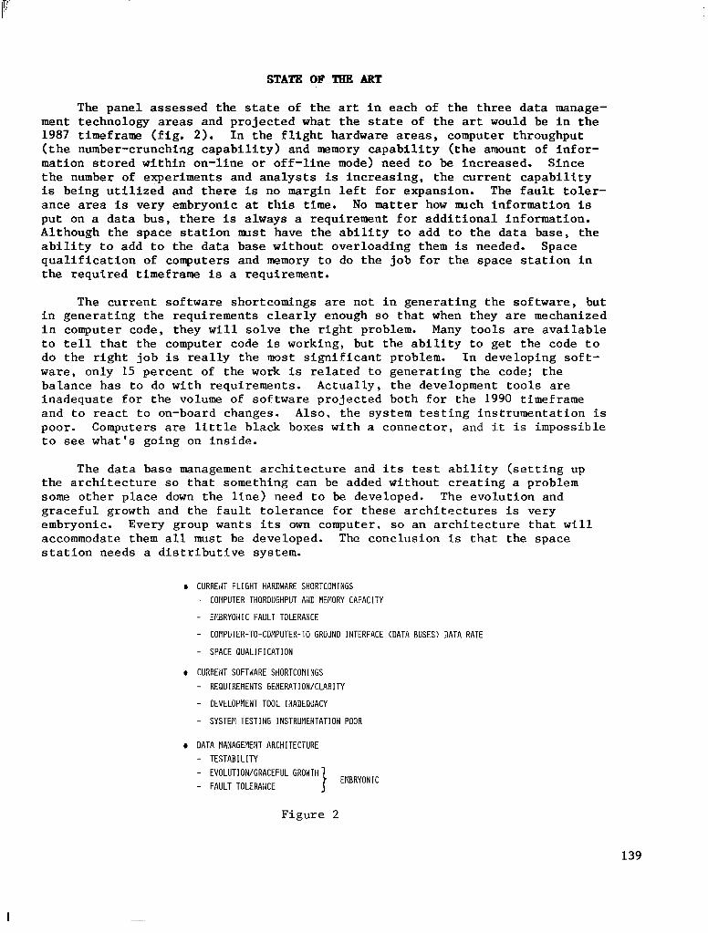
STATE OF TBE ART
The panel assessed the s ta te of t he art i n each of the three data manage- ment technology areas and pro jec ted what t h e s ta te of t h e ar t would be i n t h e 1987 t imeframe ( f ig . 2). In t he f l i gh t ha rdware areas, computer throughput ( t h e number-crunching capabili ty) and memory c a p a b i l i t y ( t h e amount of i n fo r - mat ion s tored wi th in on- l ine o r o f f - l ine mode) need t o be increased. Since t h e number of experiments and analysts i s i n c r e a s i n g , t h e c u r r e n t c a p a b i l i t y is be ing u t i l i zed and t he re is no margin l e f t f o r e x p a n s i o n . The f a u l t t o l e r - ance area is very embryonic a t t h i s time. No matter how nuch information €13 put on a da ta bus , there is always a requi rement for addi t iona l in format ion . Al though the space s ta t ion nus t have the ab i l i ty to add to the da ta base , the a b i l i t y t o add to the da ta base wi thout over loading them is needed. Space q u a l i f i c a t i o n of computers and memory t o do t h e j o b f o r t h e s p a c e s t a t i o n i n the required t imeframe is a requirement.
The current sof tware shortcomings are no t i n gene ra t ing t he so f tware , bu t i n g e n e r a t i n g t h e r e q u i r e m e n t s c l e a r l y enough so t h a t when they are mechanized i n computer code, they w i l l s o l v e t h e r i g h t problem. Many t o o l s are a v a i l a b l e t o t e l l that the computer code is work ing , bu t t he ab i l i t y t o ge t t he code t o do t h e r i g h t j o b i s r e a l l y t h e most s i g n i f i c a n t problem. In deve loping sof t - ware, only 15 percent of the work is r e l a t e d t o g e n e r a t i n g t h e c o d e ; t h e ba lance has to do with requirements . Actual ly , the development tools are inadequate for the volume of sof tware p ro jec ted bo th for the 1990 timeframe a n d t o react t o on-board changes. Also, the sys tem tes t ing ins t rumenta t ion is poor. Computers are l i t t l e black boxes with a connector, and i t is impossible t o see what 's going on in s ide .
The data base management a r c h i t e c t u r e and i t s t e s t a b i l i t y ( s e t t i n g up t h e a r c h i t e c t u r e so that something can be added without creat ing a problem some o t h e r p l a c e down t h e l i n e ) need t o be developed. The evolut ion and gracefu l g rowth and the fau l t to le rance €or these a rch i tec tures is very embryonic. Every group wants i t s own computer, so a n a r c h i t e c t u r e t h a t w f l l accommodate them a l l must be developed. The conclusion i s t h a t t h e space s t a t i o n n e e d s a d i s t r ibu t ive sys t em.
D CURREdT F L I G H T HARDWARE SHORTCOMINGS - COllPUTER THOROUGHPUT AND MEMORY CAPACITY
- EPMRYOdIC FALlLT TOLERANCE
- COMPUTER-TO-COMPUTER-TO GROUND INTERFACE (DATA BUSES) DATA RATE
- SPACE Q U A L I F I C A T I O N
a CURREiiT SOFTAARE SHORTCOMNGS - REGlUIREI.lEi.ITS GENERATIOR/CLARITY
- DEVELOPFlENT TOOL IiIADEQUACY
- SYSTEM TESTING INSTRUPlEHTATlOH POOR
D DATA MANAGEMENT ARCHITECTURE - T E S T A B I L I T Y - EVOLUTIOH/GRACEFUL GROWTH - F A U L T T O L E R A K E
Figure
EMBRYOIIIC
2
139
I
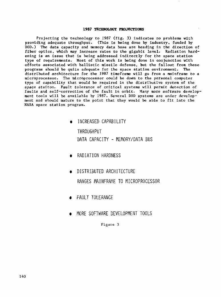
1987 TECHNOLOGY PROJECTIONS
Pro jec t ing t he t echno logy t o 1987 ( f i g . 3) i n d i c a t e s no problems with providing adequate throughput. (This is being done by indus t ry , funded by DOD.) The da ta capac i ty and memory data base are heading in t h e d i r e c t i o n of f i b e r o p t i c s , which m y i n c r e a s e rates to t he g igab i t l eve l . Rad ia t ion ha rd - ening is an i s s u e t h a t is b e i n g a d d r e s s e d i n d i r e c t l y f o r t h e space s t a t i o n type of requirements. Most of t h i s work i s being done i n c o n j u n c t i o n w i t h e f f o r t s a s s o c i a t e d w i t h b a l l i s t i c missile defense , bu t the fa l lou t f rom these programs should be qui te adequate for the space s ta t ion envi ronment . The d i s t r i b u t e d a r c h i t e c t u r e f o r t h e 1987 time.€rame w i l l go from a mainframe t o a microprocessor. The microprocessor could be down to the personal computer type of c a p a b i l i t y t h a t would be r e q u i r e d i n t h e d i s t r i b u t i v e s y s t e m of t h e space s t a i ton . Fau l t t o l e rance of cr i t ica l systems w i l l permi t de tec t ion of f a u l t s and s e l f - c o r r e c t i o n of t h e f a u l t i n o r b i t . Many more software develop- ment t o o l s w i l l be a v a i l a b l e by 1987. Seve ra l DOD systems are under develop- ment and should mature to the point that they would be a b l e t o f i t i n t o t h e NASA s p a c e s t a t i o n program.
0 INCREASED CAPAB I L I T Y
THROUGHPUT
DATA CAPACITY - MEMORY/DATA BUS
0 RADIATION HARDNESS
0 D I S T R I N T E D ARCHITECTURE
RANGES PIAINFRANE TO MICROPROCESSOR
0 FAULT TOLERANCE
0 MORE SOFTWARE DEVELOPMENT TOOLS
F i g u r e 3
140

c[JBRENT TECHNOLOGY POB PROCESSORS/STORAGE
In terms of current technology for processors and s torage ( f ig . 41, general-purpose processors with 1.5 m i l l i o n i n s t r u c t i o n s per second a r e a v a i l - a b l e now and computers with that capabili ty which are f l y a b l e are a v a i l a b l e . There are s e v e r a l signal processors ava i lab le which provide capabi l i t i es somewhere between 10 and 100 mi l l i on i n s t ruc t ions pe r s econd . The a r c h i t e c - t u r e of s igna l p rocesso r s is u s u a l l y t a i l o r e d t o t h e p a r t i c u l a r a p p l i c a t i o n , so t h a t a g iven s igna l p rocesso r , i f moved from one f a s t F o u r i e r t r a n s f o r m (FFT) t o a n o t h e r , would not achieve the same throughput capabi l i ty .
T h e r e a r e s e v e r a l v i a b l e t e c h n o l o g i e s i n t h e mass s t o r a g e area. The bubble memory system is not f l i g h t proven. There are some problems with the temperature range which must be overcome be fo re t h i s sys t em i s v i a b l e f o r a space s t a t ion . The magnetic d i s c system has not been f l ight proven e i ther . Opt ica l d i scs a re read-only devices bu t can s tore l a rge amounts of informa- t i on . The old standby magnetic tape systems is t h e most mature system and has been f l igh t p roven . Its only problem is t h e h i g h l i f e c y c l e c o s t .
0 GENERAL-PURFOSE PROCESSORS (SINGLE PROC I ELEKENT)
- 1 , 5 MIPS (MILLION INSTRUCTIONS PER SECOND) ( F I XED PO I NT I NSTRUCT IONS)
0 SIGNAL PROCESSORS - 10 MIPS TO 100's OF MIPS (FUNCTION OF TYPE OF SIGNAL
PROCESSORS AND NUMBER OF PROCESSING ELEMENTS)
0 MASS STORAGE (V IABLE TECHNOLOGIES) - BUBBLE MEMORIES: NOT FLIGHT PROVEN - RAGNETIC DISCS: NOT FLIGHT PROVEN - OPT1 CAL DISCS : READ-ONLY DEVICES
- MAGNET1 C TAPE : FLIGHT PROVEN, MOST FlATUREJ H I G H L I F E CYCLE COST
Figure 4
14 1
1987 PROJECTIONS PDR PROCESSORS/STORAGE
Pro jec t ing t he t echno logy t o 1987 ( f i g . 5) shows the p rocessor number- c r u n c h i n g c a p a b i l i t y i n c r e a s i n g t o 6 t o 10 m i l l i o n i n s t r u c t i o n s p e r s e c o n d (MIPS). This is due t o VHSIC (very h igh speed in tegra ted c i rcu i t ) t echnology going down t o t h e l o w e r f e a t u r e s i z e s i n t h e g e n e r a t i o n of t h e i n t e g r a t e d '
c i r c u i t s . S i g n a l p r o c e s s o r c a p a b i l i t y w i l l jump an o rde r of magnitude (100 t o 1000 MIPS), aga in l ower ing f ea tu re s i ze s t o i nc rease t he t h roughpu t capab i l i t y and speed. With a l i t t l e help, bubble memories w i l l be q u a l i f i e d . However, each s torage system has a d isadvantage to go with each advantage. Where t h e memory i s v i r t u a l l y u n l i m i t e d , t h e access time is l imi ted (bubble memory, magnet ic , and op t ica l d i sc) . The magnet ic tape has the highest s torage and access time, but tape involves a wa i t ing time un t i l t he t ape r eaches t he end of the ree l .
V i r t u a l memory is a requi rement for space s ta t ion da ta s torage . The a n a l y s t must have t h e c a p a b i l i t y of w r i t i n g a computer program, talking about d a t a sets, and manipulat ing the data sets without being concerned about s p e c i f i c memory l o c a t i o n s and s i z e l i m i t a t i o n . The bubble memory w i l l probably provide a s o l u t i o n t o t h e o f f - l i n e s t o r a g e problem.
0 GENERAL-PURPOSE PROCESSORS (SINGLE PROCESS1 NG ELEMEdT)
- 6 TO 10 MIP (FIXED POINT INSTRUCTIONS)
0 S I GNAL PROCESSORS - 130's TO 1000's MIPS (FUNCTION OF TYPE OF SIGNAL PROCESSORS AND
rlUP1BER OF PROCESS I NG ELEMENTS
0 MASS STORAGE
- BUBBLE MEMORIES: POTEiITIAL VIRTUAL MEMORY
MEDIUM ACCESS TIME, MEDILlM STORAGE
- MAGNETIC DISCS: POTENTIAL VIRTUAL MENORY
NED I UM ACCESS T I ME, MED-H I GH STORAGE
- OPTICAL DISC: iiON-ERASABLE, NED-H I GH ACCESS TIME, HIGH STORAGE
- MAGNETIC TAPE : OFF L I N E MASS STORAGE, HIGH ACCESS TIME,
ii I GHEST STORAGE
Figure 5
142

PROCESSING TATA POLES
Looking a t t h e t a l l po le s (largest problems) assoc ia ted wi th p rocess ing ( f i g . 6 1 , t h e most important item is development of a f a u l t - t o l e r a n t computer. This computer must p o s s e s s t h e c a p a b i l i t y t o d e t e c t a problem and resolve that problem by e i the r swi t ch ing i n ano the r compute r o r hav ing some type of s e l f - h e a l i n g c a p a b i l i t y i n t h e d i s t r i b u t i v e s y s t e m . DOD is f a r t h e r a l o n g i n t h e area of s t a n d a r a d i z a t i o n t h a n NASA. DOD has an ex is t ing s tandard 16-b i t processor and a s tandard 32-bi t processor in the ear ly development s tage. The panel unanimously recommended tha t t he space s t a t ion have s t anda rd iza t ion a t the co re l eve l . S t anda rd iza t ion is not requi red for the exper iments (many u s e r s would be l o s t ) , b u t s t a n d a r d i z a t i o n f o r t h e i n t e r c o n n e c t s t o t h e s p a c e s t a t i o n s h o u l d be developed.
0 FAULT-TOLERANT COMPUTERS
0 STANDARD I ZAT I ON
0 SPACE STATION DATA STORAGE REQUIREMENTS
0 VIRTUAL MEMORY 0 OFF-LINE STORAGE
0 INSERTION OF VHS I C TECHNOLOGY
Figure 6
143

PRIORITIZATION OF PBDCESSOR TASKS
The on-going NASA t a s k s r e l a t e d t o p r o c e s s o r s are p r i o r i t i z e d on a func- t i o n a l b a s i s a l o n g w i t h a d d i t i o n a l t a s k s t h a t t h e p a n e l c o n s i d e r e d i m p o r t a n t ( f i g . 7). The I n s t r u c t i o n S e t A r c h i t e c t u r e ( I S A ) s e l e c t i o n s s t u d y was ranked f i r s t because i t is extremely important that NASA t a k e a p o s i t i o n on t h i s v e r y e a r l y i n t h e program. The s i g n a l p r o c e s s i n g a r c h i t e c t u r e s t u d y was added because NASA has an on-going program of very high speed information processing leading to ch ip set development and the t o t a l program should have some f i r m requirements before i t goes too fa r downstream.
ISA SELECTION STUDY - ADDED TASK
FAULT-TOLERANT COMPUTER VALIDATION
FAULT-TOLERANT/CONCURRENT MICROPROCESSORS
SPACE-RADIATION-HARDENED MICROCIRCUITS SIGNAL PROCESSOR ARCHITECTURE STlJDY - ADDED TASK
FAULT-TOLERANT DATA SYSTEM
S I GNAL PROCESS1 NG BRASS BOARD
VHS IC GAAS PROCESSOR
FAULT-TOLERANT COMPONENTS
GENERAL PROCESSING UNIT CHIP SET
I I'JTEGRATED SENSOR/PROCESSOR
SPACE QUALIFIED MICROS
MODULAR GENERAL PROCESS I NG SYSTEM TERM1 NAL
Figure 7
144
PRIORITIZATION OF MASS STORAGE TbsKs
The bubble memory system has top priority i n the mass storage area ( f i g . 8 ) . Magnetic tape development and cer t i f i ca t ion was an added task but was given a lower priority at this point in time because the other systems provide the best solution for the space station.
0 BUBBLE MEMORY SYSTEM
0 OPT I CAL D I S C RECORDER 0 BUBBLE MEMORY DEVICES 0 MAGNETIC TAPE CERTIFICATION/DEVELOPMEMT - ADDED TASK
Figure 8
145
The ne twork p rov ides t he capab i l i t y t o t i e a l l of the computers together on t he space s t a t ion t o so lve no t on ly t he co re p rob lem bu t a l so t he expe r i - ment problem. Current network technology is shown i n f i g u r e 9. The s t r u c t u r e of these data bases to a l low redundancy and noninterferences is a problem. There are s e v e r a l DOD and DOD-industry e f f o r t s t h a t are dr iv ing the t echnology to deve lop the t echniques to connec t these toge ther as w e l l as the type of protocol needed to determine which system is o p e r a t i o n a l and which is not. There is work i n t h e f i b e r o p t i c d a t a bus area t o c o n s t r u c t and demonstrate the implementation, but a good a r c h i t e c t u r e i s needed t o t i e them toge the r before implementat €on.
The d i f f e r e n c e mediums of a t w i s t e d p a i r o r a coax ia l cab le are well deve loped . Opt ica l capabi l i ty i s j u s t d e v e l o p i n g i n t h e f i b e r o p t i c area.
The components s t anda rd on many DOD programs are a t 1 megabit. There are 50-megabit coax systems available commercially, but these are n o t f l i g h t qua l i f ied . There are a l s o some commercial optical point-to-point components with a c a p a b i l i t y e x t e n d i n g t o 500 megabits per second, but they w i l l not be compatible with every processor.
The network o p e r a t i n g s y s t e m t o a l l o w t h i s a r c h i t e c t u r e appears t o work but some standard development i s required. DOD and industry have some s tandards , bu t i t i s an area, i n te rms of the a rch i tec ture of the space s t a t i o n , which needs work.
e STRUCTURE
- MAJOR DODKOMMERCIAL EFFORTS DRIVING TECHNOLOGY (BUS, STAR^ RING) AND PROTOCOLS (TOKENS, RING, TOKEN Bus) (Low SIGNAL INTERFERENCE/~ERY Low SIGNAL INTERFERENCE IMPLEMENTATION)
e MEDIUM
- PAIR AND COAX ELL-DEVELOPED - OPTICAL, BROADBAND (DIGITAL) DEVELOPING
CORPONEdTS
- 1 IlBPS (PAIR) QUALIFIED
- 50 I4BPS (COAX) COMMERCIAL - 500 PIBPS (OPTICAL POINT-TO-POINT) COMMERCIAL (LARGE)
e i4ETdORK OPERATII4G SYSTEM
- STANDARDS DEVELOPING FOR COMMERCIAL/DOD
Figure 9
146

Technology i n 1987 w i l l e l iminate the problem of achieving high rates w i t h f i b e r o p t i c t y p e s of network (fig. 10). With very large scale in t eg ra - t i o n , t h e c a p a b i l i t y of t y ing s eve ra l nodes t oge the r w i l l e x i s t . With a l l t h e h a r d w a r e s h r i n k i n g i n s i z e , t h i s i n t e g r a t i o n i s becoming more of a r e a l i t y .
The s t a n d a r d i z a t i o n of p ro toco l s t ha t i n t e r f ace w i th t he ne tworks shou ld be l a i d o u t by 1987. F i b e r o p t i c s w i l l be the primary medium t o s a t i s f y t h e requirements on the space s ta t ion . S imula t ion w i l l t ake a look a t a l l t h e network nodes and simulate them t o produce a comparative set of q u a n t i t a t i v e numbers to determine which is b e s t o r p r o v i d e r e a s o n s f o r s e l e c t i n g one over the o ther and to have a realist ic t r a f f i c model of what the da ta bus w i l l look l i k e . Network operat ing systems are developed to DOD and commercial standards bu t are not set t o h a n d l e t h e d a t a rates f o r t h e s p a c e s t a t i o n . S u f f i c i e n t funding is needed to a l low th i s t o occu r fo r t he space s t a t ion env i ronmen t . The DOD f au l t - to l e ran t , s e l f - co r rec t ing ope ra t ing sys t em may be a p p l i c a b l e t o t he space s t a t ion .
0 STRUCTURE
- HIGHER RATES - SHRINKING N O D E S ( V L S I )
- STANDARDIZED ACCESS PROTOCOLS
0 F'IEDI UM - OPTICAL, BROADBAND DEVELOPED
0 COMPONENTS
- 1 GBPS (OPTICAL POINT-TO-POINT)
- COUPLERS - V L S I A T HIGHER RATES
0 S I M U L A T I O N
- COMPARAT I VE S I MULAT I ON
- REALISTIC TRAFFIC MODEL
0 NETWORK OPERATING SYSTEM
- DEVELOPED COMMERCIAL/DOD STANDARDS
- DOD DEVELOPED FAULT-TOLERANT/SELF-CORRECT I NG OPERATING SYSTEM
Figure 10
147
Network t a l l po le s i n t he s imu la t ion area ( f ig . 11) i n v o l v e e a r l y development of models to de te rmine what t h e t r a f f i c w i l l be l i k e on t h e d a t a bus and use the results from the model to der ive technology choices and set up t h e a r c h i t e c t u r e s . To qual i fy the networks, thermal problems associated with f i b e r o p t i c s must be overcome. High-performance o p t i c a l components need t o be deve loped and r e l i ab i l i t y des igns e s t ab l i shed .
0 SIMULATION - EARLY DEVELOPMENT OF MODELS AND SPACE STATION TRAFFIC - RESULTS DRIVE OTHER TECHNOLOGY CHOICES
0 QUALIFICATION - tl I GH-PERFORMANCE ii I RE INTERFACES
- OPT I CAL COMPONENTS
0 H I GH-PERFORMAtiCE OPT1 CAL COMPONENTS - DEVELOPMENT - RELIABILITY
Figure 11
148

PRIORITIZATION OF NETWORK ThSKs
The priorit izat ion of the network tasks is given in f igure 12. Development of information networks architectures and fiber optic compact technologies i s at the top of the list. Fiber optic rel iabi l i ty i s an added task.
INFORMATION NETWORK ARCHITECTURES
FIBER OPTIC COMPONENT TECHNOLOGY DEVELOPMENT AND DEMONSTRATION FOR SPACE STATION
FLIGHT DEMONSTRATION - OPTICAL BUS/NETWORK
FUTURE DATA SYSTEM CONCEPTS
OPTICAL Bus COMPONENTS
ONBOARD DATA PROCESSING AND HANDLING/FIBER OPTIC DATA Bus ENVIRONMENTAL EFFECTS ON FIBER OPTICS
OPTICAL SWITCHES
FIBER OPTIC RELIABILITY ADDED T A S K S
GATEWAYS
Figure 12
149

The development of requirements for sof tware is ext remely l abor in tens ive a t t h i s time ( f i g . 13). The r e s u l t is t h a t a l o t of t h e wrong codes are being implemented. Considerable breakage in t he code occurs because the require- ments themselves are labor in tens ive ( sk i l led communica tors are needed t o make su re t ha t t he r i gh t p rob lem is be ing so lved) . Sof tware deve lopment fac i l i t i es are spec ia l i zed . On t h e S h u t t l e , a d i f f e r e n t s o f t w a r e d e v e l o p m e n t f a c i l i t y was used for the main engines than for the on-board system. Faci l i t ies tend t o be set up for deve loping sof tware t a i lo red to the hardware . Curren t ly , moving software from one computer to another generates problems 2nd ends up as a h igh cos t f ac to r . Hopefu l ly , t he s t a t e of t h e a r t w i l l g e t away from t h i s p r a c t i c e and emphasize development of sof tware suppor t sys tems tha t are not as s p e c i a l i z e d .
Since a l l data systems seem t o be independent of one another , a l inkage needs to be developed. Software systems are real time driven a t the p resent . Curren t ly , the sof tware i s opt imized for a spec i f ic computer , bu t i f the problem gets outs ide the limits of the computer, then the cost of t r y i n g t o opt imize the code to f i t the sys tem increases . Networks and d i s t r ibu t ion are l i m i t e d and t a i l o r e d t o a special ly designed computer , so t h a t s t a n d a r d i z a t i o n i s separate . The c a p a b i l i t i e s of the processors are l i m i t e d by the resources of memory and throughput capabi l i ty of the machine.
0 SOFTWARE DEVELOPPIENT
0 DEVELOPMENT OF REQUIREMENTS AND SOFTWARE I S LABOR INTENSIVE EFFORT
0 S P E C I A L I Z E D S O F T W A R E D E V E L O P M E N T F A C I L I T I E S
0 $40 STANDARD LANGUAGES OR PROTOCOLS
0 I I I G H C O S T
0 SOFTlARE SYSTEMS
0 MULTIPLE INDEPENDENT DATA SYSTEMS
0 REAL-TIME DATA DRIVEN
0 LIMITED NETWORKS AND DISTRIBUTION
0 CAPABILITIES/PROCESSES LIMITED BY ONBOARD RESOURCES
Figure 13
150

1987 SnSTKMS/SOFIWARE TEcBNoLoGp PBOJECTIO~S
By 1987, automation w i l l reduce cost of requirements documentation and maintenance (fig. 14). Several systems exist today which set up a s t anda rd way of d e f i n i n g what requirements are for software. Once these types of systems are used to def ine requi rements , any change is easier t o implement i n terms of the requirements documentation, as w e l l as i n t h e f i n a l code. Auto- mation (automated tools) w i l l also reduce development testing. Standardiza- t i on i n l anguages , i n t e r f aces and p ro toco l s , and a development environment w i l l increase.
An ex tens ive improvement i n on-board resources w i l l occur by 1987, wi th t h e c a p a b i l i t y of v i r t u a l memories a v a i l a b l e . A d i s t r i b u t i v e a r c h i t e c t u r e a l lows t he add i t ion of another p rocessor ins tead of shoehorning in to a s i n g l e processor. Software systems w i l l be dr iven by real-time bulk data processing.
8 SOFTVASE DEVELOPMENT
-AUTOMATION WILL REDUCE COST OF
0 REQU I REMEWTS DOCUMENTAT I ON AND MA I HTENANCE
0 SOFTWARE DEVELOPMENT TEST I I4G AND I"1AI NTENANCE
-STANDARD I ZAT I ON I N
0 LANGUAGES 8 INTERFACES/PROTOCOLS 8 DEVELOPMENT ENVI RONMEPJT
8 SOFTWARE SYSTEMS -EXTENSIVE IMPROVEMENT I IJ ONBOARD RESOURCES -DRIVEN BY REAL TIME AND BULK DATA PROCESSING -DISTRIBUTED SYSTEMS -EXTENSIVE I4ETWORKS -APPLICABLE DATA BASE MANAGEMENT SYSTEMS
Figure 14
151

The p r i n c i p a l t a l l pole is d a t a s y s t e m a r c h i t e c t u r e d e f i n i t i o n , w h i c h i s set up so t h a t t h e a r c h i t e c t u r e c a n e v o l v e o v e r t h e e n t i r e l i f e of the space s t a t i o n and accommodate new technologies of adding processors ( f ig . 15). The c o s t of on-board software development and testing involves the development of more test t o o l s . The absence of a car ryover s tandard iza t ion f rom program to program e x i s t s now. R e s t r i c t i o n s i n on-board func t ions are due t o r e s o u r c e s and include data base management ( cu r ren t ly unab le t o hand le d i s t r ibu ted da t a base systems) , u s e r f r i e n d l y c a p a b i l i t y , and networks. Data base management sys t ems a r e , i n terms of technology, not too bad f o r t h e commercial world but have not been adequately applied to the engineering environment. User- f r i e n d l y c a p a b i l i t y a p p l i e s t o t h e d a t a b a s e a l s o .
0 DATA SYSTEM ARCHITECTURE DEFIk IT ION FOR SYSTEM EVOLUTIOWGRACEFUL GRONTH
0 COST OF ONBOARD SOFTWARE DEVELOPMENT AND TEST1 NG 0 ABSENCE OF CARRYOVER/STANDARDIZATION FROM PROGRAM TO P40GRAI: 0 RESTRICTIONS ItJ ONBOARD FUHCTIOK DUE TO RESOURCES
DATA BASE MANAGEMENT
USER FRIENDLY
NETWORKS
Figure 15
152
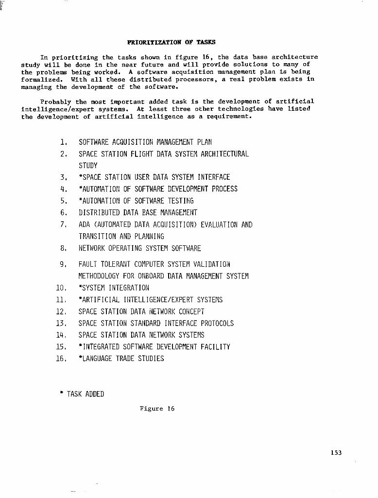
PRIORITIZATION OF TASKS
In p r i o r i t i z i n g t h e t a s k s shown i n f i g u r e 16, t he da t a base a r ch i t ec tu re s tudy w i l l be done i n t h e n e a r f u t u r e and w i l l p r o v i d e s o l u t i o n s t o many of the problems being worked. A so f tware acqu i s i t i on management p l an is being formalized. With a l l t h e s e d i s t r i b u t e d p r o c e s s o r s , a real problem exists i n managing the development of the sof tware.
Probably the most important added task is the development of a r t i f i c i a l in te l l igence /exper t sys tems. A t least three o ther t echnologies have l i s ted t h e development of a r t i f i c i a l i n t e l l i g e n c e as a requirement.
1, 2,
8,
9 ,
SOFTWARE A C B U I S I T I O t i ,FlANAGE!lEF;iT PLAPl
SPACE STATION FLIGHT DATA SYSTEV ARCHITECTURAL
STUDY
*SPACE STATION USER DATA SYSTEM INTERFACE
"AUTOMATI OR OF SOFTWARE DEVELOPMENT PROCESS
"AUTOMAT I Or4 OF SOFTWARE TEST I k G DISTRIBUTED DATA EASE MANAGEPlEiJT
ADA (AUTOMATED DATA ACQU I S I T I ON) EVALUAT I ON AND
TRANS I T 1 ON AND PLANNING
NETWORK OPERATING SYSTEM SOFTWARE
FAULT TOLERANT COMPUTER SYSTEM V A L I D A T I O N
METHODOLOGY FOR ONBOARD DATA MANAGEMENT SYSTEM
*SYSTEM INTEGRATION
* A R T I F I C I A L I N T E L L I G E : 4 C E / E X P E R T S Y S T E X
SPACE STATION DATA iJETWORK CONCEPT
SPACE STATIOiJ STAI'JDARD INTERFACE PROTOCOLS
SPACE STATION DATA WETWORK SYSTEMS
" INTEGRATED SOFTNARE DEVELOPMENT FACILITY
"LANGUAGE TRADE STUD I ES
* TASK ADDED
Figure 16
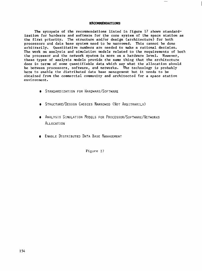
RECOHHENDATIONS
The synopsis of the recommendations l i s t e d i n f i g u r e 17 shows s tandard- i za t ion fo r ha rdware and so f tware fo r t he co re sys t em of t h e s p a c e s t a t i o n as t h e f i r s t p r i o r i t y . The s t r u c t u r e a n d / o r d e s i g n ( a r c h i t e c t u r e ) f o r b o t h processors and data base system need to be narrowed. This cannot be done a r b i t r a r i l y . Q u a n t i t a t i v e numbers are needed t o make a r a t i o n a l d e c i s i o n . The work on a n a l y s i s and s imula t ion models r e l a t e d t o t h e r e q u i r e m e n t s of both the processor and the network system is more on a hardware level . However, t hese t ypes of a n a l y s i s models provide the same t h i n g t h a t t h e a r c h i t e c t u r e does in terms of some quant i f iab le da ta which say what t he a l loca t ion shou ld be between processors, software, and networks. The technology is probably he re t o enab le t he d i s t r ibu ted da t a base management but i t needs to be obtained from the commercial community a n d a r c h i t e c t e d for a s p a c e s t a t i o n environment.
0 STANDARD I ZAT ION FOR HARDWAREISOFTWARE
0 STRUCTURE/DESIGN CHOICES NARROWED (NOT ARBITRARILY)
0 ANALYSI s SIMULATION MODELS FOR PROCESSOR/SOFTWARE/NETWORKS ALLOCAT I ON
0 ENABLE DISTRIBUTED DATA BASE PIANAGEMENT
Figure 1 7
154
POWER
Robert Corbett Lockheed Missiles and Space Company
Sunnyvale, California
Space Station Technology Workshop Williamsburg, Virginia
March 28-31, 1983
155
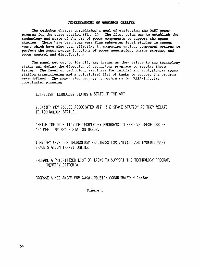
The workshop c h a r t e r e s t a b l i s h e d a goa l of e v a l u a t i n g t h e OAST power program for t h e s p a c e s t a t i o n ( f i g . 1). The f i r s t p o i n t was t o e s t a b l i s h t h e technology and state of t h e ar t of power components t o suppor t t he space s ta t ion. There have been some very f ine subsys tem level s t u d i e s i n r e c e n t years which have a l s o b e e n e f f e c t i v e i n comparing various component o p t i o n s t o perform the power system funct ions of power genera t ion , energy s torage , and power c o n t r o l and d i s t r i b u t i o n .
The panel set o u t t o i d e n t i f y key i s s u e s as they relate to the t echnology s t a t u s and d e f i n e t h e d i r e c t i o n of technology programs to resolve those i s sues . The l eve l o f t echno logy r ead iness fo r i n i t i a l and evo lu t iona ry space s t a t i o n t r a n s i t i o n i n g and a p r i o r i t i z e d list of t a s k s t o s u p p o r t t h e program were def ined. The panel a lso proposed a mechanism f o r NASA-industry coordinated planning.
ESTABLISH TECHNOLOGY STATUS 8 STATE OF TkE ART.
IDENTIFY KEY ISSUES ASSOCIATED WITH THE SPACE S T A T I O l AS THEY RELATE TO TECHNOLUtiY STATUS I
DEFINE THE DIRECTION OF TECHNOLOGY PROGRAMS TO RESOLVE THESE ISSUES A# MEET THE SPACE STATION NEEDS,
IDENTIFY LEVEL OF TECHNOLOGY READINESS FOR I N I T I A L AND EVOLUTIONARY SPACE STAT I ON TRANS I T I ON I NG ,
PREPARE A PRIORITIZED LIST OF TASKS TO SUPPORT THE TECHNOLOGY PROGRAM. IDENTIFY CRITERIA,
PROPOSE A MECHANISM FOR NASA- IHDUSTRY COORDINATED PLANNING
Figure 1
156

POWER PBoGBdw OVERVIEW
It is i m p o r t a n t t o r e a l i z e t h a t t h e s p a c e s t a t i o n r e q u i r e s a n i n c r e a s e i n power or energy of a t least s e v e r a l o r d e r s of magnitude compared to p rev ious space missions. With the requirement up in t he r ange of 10 k i lowat t hours , this obviously requires the development of new technology. Although the power area is very well i n t e g r a t e d i n t h e s p a c e c r a f t i t s e l f , it rep resen t s a d i v e r s e set of components necessary for energy convers ion , e lec t ronics , and energy d i s t r ibu t ion . Cons ide rab le work is ongoing a t NASA L e w i s i n t h e power devices development area, inc luding t ransformers , l a rge area so l id - s t a t e ch ips , t r an - s i s t o r s , and fas t recovery d iodes . This work is or iented toward eventual a p p l i c a t i o n t o b o t h AC and DC power conversion approaches. In the energy s to rage area, t h e r e are many o p t i o n s a v a i l a b l e t o f i t i n t o t h e s p a c e s t a t i o n represent ing var ious degrees of r i s k and leverage combination, such as t he near- term integral-pressure-vessel n ickel-hydrogen bat tery, an advanced Ni-H2 bat tery concept , and the regenerat ive hydrogen-oxygen system u t i l i z i n g e s s e n t i a l l y t h e S h u t t l e o r b i t e r t y p e of f u e l ce l l . Also, there is t h e s o l i d polymer e l e c t r o l y s i s and f u e l c e l l u n i t ( a c i d f u e l ce l l ) which has the advantage of i n t eg ra t ing ve ry w e l l w i th t he l i f e suppor t and r eac t ion con t ro l systems.
Most of t he cu r ren t power work relates t o s o l a r power and photovol ta ics , bu t there is a l s o work on nuclear power which u l t ima te ly is a p p l i c a b l e t o t h e space s t a t ion bu t is no t c l ea r ly app l i cab le a t the present because of the absence of c l e a r s p a c e s t a t i o n time l i n e s . The nuclear power system has cer ta in in te res t ing advantages , no tab ly reduced drag .
A so la r a r ray f l igh t exper iment , based on t h e o r i g i n a l s o l a r e l e c t r i c propuls ion (SEP) array technology, is schedu led t o f l y on an STS mission next year . It is e s s e n t i a l l y a dynamic test bed f o r t h e f l e x i b l e s o l a r array system. Other advanced solar array concepts with perhaps lower costs but h ighe r r i sks are being s tudied. These include var ious concentrator approaches , such as cassegranian (h igh concent ra t ion ra t io) and f l a t p l a t e ( l o w c o n c e n t r a t i o n r a t i o ) .
157
I
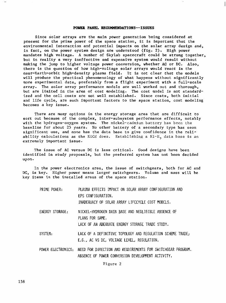
POVKB PANEL RECOWNENDBTIONS-ISSUES
S i n c e s o l a r a r r a y s are the main power generat ion being considered a t present for the p r ime power of the space s t a t i o n , it is impor tan t tha t the envi ronmenta l in te rac t ion and po ten t ia l impacts on t he so l a r a r r ay des ign and , i n f a c t , on t h e power system design are unders tood ( f ig . 2). High power mandates high voltage. A number of Skylab spacecraf t could be s t rung together , b u t i n r e a l i t y a v e r y i n e f f e c t i v e and expensive system would r e s u l t w i t h o u t making the jump t o h i g h e r v o l t a g e power conversion, whether AC o r DC. Also, t h e r e is t he ques t ion of how h igh-vo l t age so l a r a r r ays would react i n t h e near-Earth-orbit high-density plasma f i e l d . It is not clear t h a t t h e models w i l l p roduce the p rac t ica l phenomenology of what happens wi thout s ign i f icant ly more exper imenta l da ta , p referab ly from a f l igh t exper iment wi th a f u l l - s c a l e a r r a y . The solar array performance models are well worked out and thorough, but are l i m i t e d i n t h e area of cost modeling. The cos t model is not standard- ized and the ce l l c o s t s are not well e s t a b l i s h e d . S i n c e c o s t s , b o t h i n i t i a l and l i f e c y c l e , are such impor tan t fac tors to the space s ta t ion , cos t model ing becomes a key issue.
There are many opt ions in the energy s torage area t h a t are d i f f i c u l t t o sor t out because of t he complex, inter-subsystem performance effects, notably with the hydrogen-oxygen system. The nickel-cadmium b a t t e r y h a s b e e n t h e base l ine fo r abou t 25 years . No o t h e r b a t t e r y of a secondary type has seen s i g n i f i c a n t u s e , and none has t h e d a t a b a s e t o g i v e c o n f i d e n c e i n t h e reli- a b i l i t y c a l c u l a t i o n s as the NiCd does . Es tab l i sh ing a Ni-H, da ta base i s an extremely important issue.
The i s s u e of AC versus DC is less c r i t i ca l . Good designs have been iden t i f i ed i n s tudy p roposa l s , bu t t he p re fe r r ed sys t em has no t been decided upon.
I n the power e l e c t r o n i c s area, the i s sue of swi tchgears , bo th for AC and DC, is key. Higher power means la rger swi tchgears . Volume and mass w i l l be key items i n t h e i n s t a l l e d areas of t he space s t a t ion .
PRIME POWER:
ENERGY STORAGE:
SYSTEM :
POWER ELECTRONICS:
PLASMA EFFECTS IMPACT ON SOLAR ARRAY CONFIGURATION AND EPS CONFIGURATION, INADEQUACY OF SOLAR ARRAY LIFCCYCLE COST MODELS,
NICKEL-HYDROGEN DATA BASE AND NEGLIEIELE ABSENCE OF PLANS FOR SAME, LACK OF AN ADEQUATE ENERGY STORAGE TRADE STUDY,
LACK OF A DEFINITIVE TOPOLOGY AND REGLjLATION SCHEME TRADE; EmGI, AC VS DC, VOLTAGE LEVEL, REGULATION,
NEED FOR DIRECTION AND REQUIREMENTS FOR SWITCHGEAR PROGRAM. ABSENCE OF POWER CONVERSION DEVELOPMENT ACTIVITY
Figure 2
158

POWER PANEL, RECOMMENDATIONS-DIRECTIONS
Funds for technology are limited, but an aggressive environmental and materials compatibility program for solar power needs to be pursued, with emphasis on flight experiments and array-specific modeling (fig. 3 ) . (The model can handle the planar array, but not the concentrator array.) Periodic system studies, or subsystem level studies, will aid in controlling component R&D work, auditing R&D work, and directing future component activity. Since there are four or five kinds of energy storage, the question of eliminating one or more for the improvement of perhaps the best candidate arises. When this inter-subsystem or component trade is conducted, some indicators of relative performance merit, mass, volume, heat dissipation, and cost can be obtained. However, without space station requirement sets or configuration sensitivities, the competency to make that selection does not exist. For example, for the solar array, different area performance figures have been projected for the various array options. Drag, especially in the Shuttle parking orbit, is a critical issue, but the relative importance of drag, as compared to mass, volume, or initial cost, is unknown.
PURSUE AN AGGRESSIVEJ STEPPED-UP ENVIRONMENTAL AND MATERIALS COMPATIBILITY PROGRAM EMPHASIZING FLIGHT EXPERIMENT AND ARRAY-SPECIFIC MODELING,
CONTINUE TO FUND OCCASIONALJ REGULAR SUBSYSTEM STUDIES TO AUDIT R8D EFFORT DEFINE SYSTEM IMPACT OF COMPOKENT IHPROVEMENTS DIRECT FUTURE COMPONENT WORK
MAINTAIN ALL PRESENT ELEMENTS OF THE OAST POWER PROGRAM IN ANTICIPATION OF SPACE STATION REQUIREMENTS/CONFIGURATION STUDIES,
Figure 3
159

TECENOLOGP READINESS DETERMINATION
Cur ren t , t r ad i t i ona l gu ide l ines shou ld be fol lowed in technology t ransi- t i o n i n g ( i d e n t i f y i n g t h e l e v e l of technology a t which t r ans i t i on shou ld occu r ) . Once a proof of concept, a reasonably adequate data base, is obtained and an a p p l i c a t i o n exists, t h e program should be transit ioned to advanced development, a development within the context of t h e s p e c i f i c program ( f ig . 4). I f t r a n s i - t i o n i n g is not done, the funds for detailed hardware w i l l come from scarce technology resources and future technology suffers . It is impor tan t tha t when a product goes on-line, the same technology funds should be used for the increased performance, which produces improved performance on t h e e v o l u t i o n a r y s t a t ion.
A f l i g h t t e s t i n g a p p r o a c h ( o b t a i n i n g t h e d a t a b a s e in f l i g h t ) would reduce cos t ly da t a base and demons t r a t ion e f fo r t s . With r e g u l a r s e r v i c i n g , it is not necessary t o know t h a t a b a t t e r y w i l l l a s t 2 , 3 , 4 , o r 5 years . It may only l as t f o r 1 year . The c a l c u l a t e d r i s k w i t h e a r l y s e r v i c i n g w i l l save develop- ment and da ta base cos ts .
(A> AT THE MOST: FOLLOW THE PRESENT GUIDELINE:
TRANSITION TECHkOLOGY AT COMPLETION PROOF OF CONCEPT TO ADVANCED DEVELOPMENT FUNDING ,
T H I S FOCUSES SCARCE TECHNOLOGY FUNDS TO HIGH PERFORMANCE
EVOLUTIONARY APPROACHES,
(B) CONSIDER A F IELD TEST1 NG APPROACH TO REDUCE COSTLY DATA BASE AND
DEMONSTRATION EFFORTS,
Figure 4
160

,!) PRIORITIZED LIST
Ins t ead of a p r i o r i t i z e d l ist , the power pane l p re fe r s many technology opt ions tha t can be used when the program t ime l ine is unders tood ( f ig . 5 ) . Current ly , there are some b ig unce r t a in t i e s abou t space s t a t ions . One is conf igu ra t ion , and the o the r i s exac t ly when t h e s p a c e s t a t i o n w i l l occur. These are working ground rules, but to make a c r i t i ca l component dec i s ion a t t h i s p o i n t would be t o e s t a b l i s h a development r isk for one component or , a t t he o the r extreme, t o f l y a very sub-optional component f o r t h e t i m e l i n e of t h e s p e c i f i c s t a t i o n . Enough information is not ava i lab le to rank the t ech- nology program p r i o r i t i e s . The s e n s i t i v i t y f a c t o r s are needed t o make t h a t s e l ec t ion p rocess . The technology program can be focused, but that essen- t i a l l y h a s t o wait u n t i l a f t e r t h e r e q u i r e m e n t s , d e f i n i t i o n , and program t ime l ine de f in i t i on p rocesses . The pane l e s t ab l i shed a top - l eve l p r io r i t i za - t ion based on c o n f i g u r a t i o n s e n s i t i v i t y .
INFORMATION IS NOT AVAILABLE TO RANK ORDER ENTIRE TECHNOLOGY PROGRAM.
ALTERNATE COKEPT SELECTION OR PRIORITIZATION REQUIRES SYSTEM SENSITIVITY FACTORS BASED ON SS SYSTEM CONFIGURATION,
TECHNOLOGY PROGRAM CAN AND SHOULD BE FOCUSED BUT THIS REQUIRES:
REQU IREME;,iTS FLO!dDOWN AKD REFERENCE CONFIGURATION. ADOPTION OF A SS DEVELOPMENT TIMELINE.
WE CAr.1 ESTABLISH A TOP-LEVEL PRIORITIZATION BASED O N COi'lFIGURATIO?i SENSITIVITY.
F i g u r e 5
161

TOP-LEVEL PRIORITY LIST
The t o p - l e v e l p r i o r i t y l i s t ( f i g . 6 ) d o e s n o t r e f l e c t a c c u r a t e l y what t h e rea l problems are, which of the areas requ i r e more a t t e n t i o n , and which of t h e areas do not include performance as a concern. The i m p o r t a n t t h i n g t o r e a l i z e is t h a t t h e r e are n o t s a t i s f a c t o r y d a t a a t the p re sen t t o g ive t he conf idence t o f l y what is c a l l e d a high voltage system. Such a system, i f nominal ly a 140-volt system, would have a peak so la r a r r ay vo l t age approach ing 500 v o l t s . S t i l l h ighe r nomina l bus voltages would exceed th i s peak leve l . A convent ional system (28 v o l t ) is one which has a s o l a r a r r a y (S/A) which t y p i c a l l y runs from perhaps 40 v o l t s a t nominal operat ion to as high as 70 v o l t s d u r i n g exi t from the ec l ip se o r unde r some kind of shaded condition. Skylab was a l i t t l e b i t higher than s tandard, about a 40- t o 50-watt nominal power system supply vol tage wi th an a r ray which operated a t about 50 o r 60 v o l t s a t opera t ing temperature and could go as high as 100 or 120 v o l t s . Not having the informa- t i o n on t h e s o l a r a r r a y t o g i v e c o n f i d e n c e t o f l y a h igher vo l tage a r ray w i l l mean r e s o r t i n g t o f l i g h t q u a l i f i c a t i o n d a t a o r f l y i n g a n a r r a y w i t h t h e same series complement of cel ls and up-converting (using a transformer-type conve r t e r ) t o a more e f f ec t ive vo l t age .
The present photovol ta ics and energy storage program should be maintained. There is a r ank ing r e l a t ionsh ip he re i n t he s ense t ha t t he ene rgy s to rage and power genera t ion are a b i t more important than the power e lec t ronics because the conf igura t ion of t he space s t a t i o n is more s e n s i t i v e t o t h a t t e c h n o l o g y than i t is t o t h e power e l e c t r o n i c s . The power e l e c t r o n i c s is a l s o a smaller f r a c t i o n of t h e t o t a l s y s t e m and is a t a b e t t e r s tate of development.
The envi ronmenta l in te rac t ion i s an enabl ing technology and t h e o t h e r i s s u e s l i s t e d i n f i g u r e 6 are enhancing technologies because they are essen- t i a l l y p e r f o r m a n c e r e l a t e d .
ENV I RONMENTAL I NTERACT I ON/ S/A, POWER CONTROL MATERIALS COMPATIBILITY DESIGN IMPACT
""_"_"" MAY DRIVE 50 - 60V I S / A m
MA I NTA IN PRESENT : CAN'T SELECT WITHOUT SPACE SOLAR POWER PROGRAM S T A T I O I I S E N S I T I V I T I E S AN0 ENERGY STORAGE PROGRAM TIMELINE, VARIOUS RISK/
LEVERAGE LEVEL I
MA I NTA I N POWER DEVICES PROGRAM AUGMENT WITH: AC AND DC SWITCHGEAR, IMPORTANT AND SUCCESSFUL
POWER CONTROL CONVER- REQU I RES CONF IGURAT IO!q SION I STUDIES TO RESOLVE
ULTIYATE SELECTION,
Figure 6
162

“ U S M FOR NASA-INDUSTRY OOORDINATION
The issue of how to continue this panel process to feed information directly from the functional organizations to the Space Station Technology Steering Committee was addressed (fig. 7) . Existing committees have a full docket of commitments, so they would not be able to address this process with a great deal of depth and breadth. They would not necessarily have the right people, the right currency, or the right turnover in the sense of representing the working engineer who is currently doing space station work. A new commit- tee, similar to this panel but smaller, totally responsive to space station needs and reporting to the Space Station Technology Steering Committee, would do the job very well.
OPT IONS : NEW GROUP -- SIMILAR TO THIS PANEL BUT SMALLER
AIAA SPACE POWER COMMITTEE
IEEE ELECTRICAL POWERiENERGY SYSTEMS PANEL
SPACE SYSTEPlS TECHNICAL ACTIVIT IES COMMITTEE POWER SUBCOMMITTEE
EVALUATION:
RESOLUTION:
EXISTING GROUPS HAVE FULL CHARTER/COMMITMENTS ARE HIGHER UP ORGANIZATIONALLY DON‘T HAVE TURNOVER WHICH IS NEEDED TO MAINTAIN BALANCE,
NEW COMMITTEE, TOTALLY RESPONSIVE TO SS NEEDS REPORTIi\IG TO SSTSC,
Figure 7
163


Bob Haslett Grumman Aerospace Corporation
Bethpage, New York
Space Station Technology Workshop Williamsburg, Virginia
March 28-31, 1983
165

TECENOLOGY APPLICATION TO SPACE STATION ACTIVE TBE- CONTROL
There are b a s i c a l l y t h r e e key ing red ien t s t o t he t he rma l con t ro l sys t em f o r any la rge space p la t form or space s ta t ion . These are hea t re jec t ion ( f rom a c e n t r a l i z e d r a d i a t o r o r from body-mounted r ad ia to r s ) , hea t acqu i s i t i on ( f rom payloads) , and heat t ransport (via a t r a n s p o r t l o o p t o t h e r a d i a t o r ) . The system shown i n f i g u r e 1 is similar to t he Shu t t l e sys t em. The S h u t t l e h a s f l u i d l o o p r a d i a t o r s i n t h e d o o r s , c o l d p l a t e s , and a pumped Freon l iqu id loop which takes hea t to the rad ia tor .
CENTRAL HEAT REJECTION (GIMBALED SPACE CONSTRUCTABLE RADIATOR)
HEAT TRANSPORT (TWO- lllllr;;\
LMODULE HEAT REJECTION
HEAT ACQUISITION (INTEGRAL HEAT (CONTACT HEAT PIPE RADIATOR/ EXCHANGER METEOROID EVAPORATORS) SHIELD)
F i g u r e 1
166

THEBPIBL ISSUES/PROBLEXS
The first objective in considering thermal control is to determine if the space station requirements present new thermal issues and/or problems which would indicate that the current approach is not the one to continue pursuing (fig. 2) . The space station will be an indefinite in-orbit type system, as opposed to the several-week sortie of the Shuttle. This makes the meteoroid hazard to the radiators and the degradation of thermal coatings much more important issues, and points in the direction of repair procedures or modular construction allowing replacement. The station will try to accommodate many more users, so users would benefit greatly if there were a standard thermal condition or several standard conditions which could be specified to facilitate design of individual equipment. Some users will require cold plates, others will want fluid connections to a thermal system. Therefore, diverse interfaces are needed. The other key issues are much more efficient operation, growth, and maintenance. The space station cannot tolerate the large amount of crew or ground involvement presently required. This suggests automated control of the thermal system. Maintenance is necessary to achieve open-ended mission life, and this indicates the need for modular design and fault detection and isolation.
0 LONG LIFE RADIATOR - MICROMETEOROIDS AND DEBRIS - COATINGS
0 USER FRIENDLY HEAT TRANSPORT LOOP - KNOWN THERMAL CONDITIONS - DIVERSE INTERFACE OPTIONS
0 EFF IC I ENT OPERATI ON/GROWTH/MA I NTENANCE - AUTOMATED CONTROL - MODULAR - FAULT DETECTION AND ISOLATION
Figure 2
167

NASA ACTIONS TO DBTE
This workshop is by no means t h e f i r s t a t t e m p t t o assess t h e s e i s s u e s ( f i g . 3 ) . In f a c t , NASA has had a Thermal Working P a n e l f o r a number of years . This pane l recognized the benef i t s of i nco rpora t ing new technology i n t o t h e s p a c e s t a t i o n . S p e c i f i c c r i t i ca l long lead items were i d e n t i f i e d , sys tem t rade s tud ies were i n i t i a t e d t o i d e n t i f y a p p r o a c h e s t o be taken, and ear ly p ro to type hardware cont rac ts were le t . Ea r ly i nves tmen t i n i nhe ren t ly re l iab le /main ta inable sys tems was i d e n t i f i e d as the key t o l ower l i f e cyc le cos t s fo r t he space s t a t ion . P l ans t o pu r sue t hese new technologies came from these government working groups.
0 RECOGNIZED BENEFITS OF NEW TECHNOLOGY
0 INITIATED NUMBER OF MODERATE EFFORTS ON CRITICAL LONG LEAD TECHNOLOG I ES
0 IDENTIFIU) RELIABILITY/MAINTAINAElLITY AS KEY TO LOWER L IFE CYCLE COSTS
0 DEFINED A PLAN TO REALIZE THESE BENEFITS ON SPACE STATION
F i g u r e 3
168
TECHNICAL APPROACB
The t echn ica l app roach i n t he hea t r e j ec t ion area ( f i g . 4) is t o c o n s t r u c t t h e r a d i a t o r from individual e lements so t h a t i t can be bu i l t on -o rb i t , is very in sens i t i ve t o me teo ro id and debr i s hazards , and is r e p a i r a b l e . T h i s c l e a r l y p o i n t s i n t h e d i r e c t i o n of changing from the Shuttle 's pumped l iquid- loop r a d i a t o r s , where a s ing le punc tu re w i l l d r a i n o u t , i n t h e S h u t t l e ' s case, ha l f the system (one of t h e s i d e s of t h e s y s t e m ) . F o r i n d e f i n i t e l i f e , m u l t i p l e elements are r e q u i r e d i n t h e r a d i a t o r sys t em, so t h a t a f a i l u r e i n any one i s not ca tas t rophic . There are three approaches to the coat ing problem: rotate t he r ad ia to r s t o r educe t he time t h e r a d i a t o r looks a t the Sun and hence the sens i t i v i ty t o coa t ing deg rada t ion , ma in ta in t he coa t ing , o r deve lop a more s t a b l e c o a t i n g . A l l th ree approaches requi re advances in the cur ren t technology.
The heat t ransport loop issue points toward new technology, away from t h e S h u t t l e ' s pumped l i q u i d l o o p t o a two-phase loop which would operate a t a constant temperature ( a l l u s e r s would see t h e same condi t ions) . Evapora t ive cold plates can accommodate approximately a f a c t o r of 10 h ighe r hea t f l ux t han the cu r ren t Shu t t l e co ld p l a t e , and use r s a r e no t s ens i t i ve t o t he p l acemen t of the equipment on the loop s ince the loop temperature does not go up as the flow goes through each piece of equipment. The key i n t e g r a t i o n i s s u e s a r e t o s a t i s fy t he d ive r se u se r s w i th va r ious i n t e r f aces and to p rovide the t ech- n o l o g y f l e x i b i l i t y needed to suppor t an evo lv ing s t a t ion a r ch i t ec tu re .
HEAT REJECTION 0 HIGH CAPACITY HEAT PIPE RADIATOR
- INDEPENDENT ELEMENTS (EACH 1-2 KW) - OH-ORBIT ASSEMELY/REPlACEMENT (KIN ASTRONAUT INVOLVEMENT) - ROTATABLE RADIATOR AFiD/OR MAINTAINABLE COATING
HEAT TRANSPORT LOOP -" 0 TWO PHASE EVAPORATIVE AND CONDENSING COD PLATES)
- COFISTANT TEMPERATURE LOOP - VERY HIGH HEAT FLUX CAPABILITY - COOLANT TEMP NOT DEPENDENT ON EQUIPMENT PLACENENT OR HEAT LOAD
SYSTEM INTEGRATION 0 DIVERSE USERS
- VARIOUS INTERFACES; COLD PLATE, FLUID, DRY CONTACT, DISCONNECTS 0 STATION ARCHITECTURE
- DISTRIBUTED STATIONS, OTV'S, BACKPACK, SATELLITE SERVICING
Figure 4
169
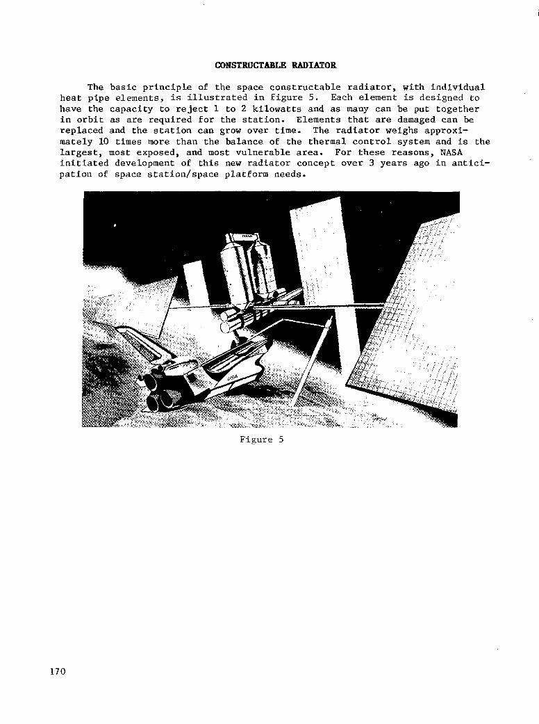
CONSTRUCTABLE RADIATOR
The b a s i c p r i n c i p l e of t he space cons t ruc t ab le r ad ia to r , w i th i nd iv idua l heat p ipe e lements , i s i l l u s t r a t e d i n f i g u r e 5. Each element i s designed t o have the capaci ty t o reject 1 t o 2 k i l o w a t t s and as many can be put together i n o r b i t as are r equ i r ed fo r t he s t a t ion . E lemen t s t ha t are damaged can be replaced and the s ta t ion can grow over time. The rad ia tor weighs approxi - mately 10 times more than the balance of the thermal control system and is the l a r g e s t , most exposed, and most vu lnerable area. For these reasons , NASA in i t ia ted deve lopment of t h i s new rad ia tor concept over 3 years ago i n a n t i c i - pa t ion of space s ta t ion /space p la t form needs .
F igure 5
170
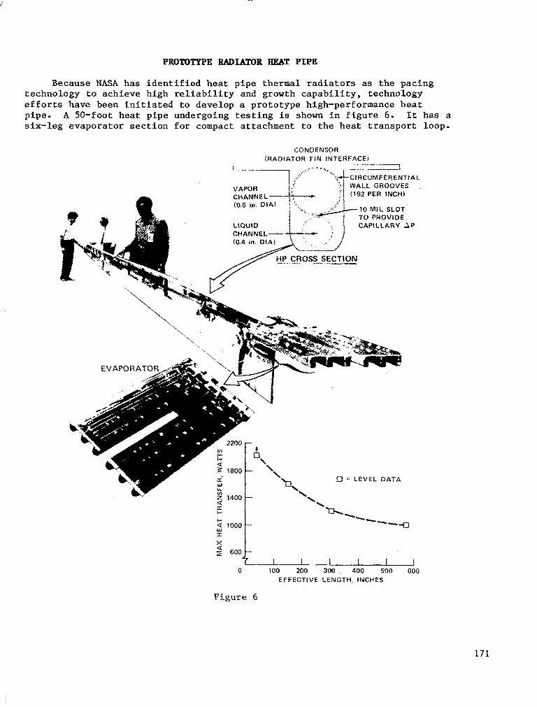
PROTOTYPE RADIATOR BEAT PIPE
Because NASA has i den t i f i ed hea t p ipe t he rma l r ad ia to r s as the pac ing t e c h n o l o g y t o a c h i e v e h i g h r e l i a b i l i t y and growth capabili ty, technology e f f o r t s h a v e been i n i t i a t e d t o d e v e l o p a prototype high-performance heat pipe. A 50-foot heat p ipe undergoing tes t ing is shown in f i g u r e 6 . It has a s ix- leg evapora tor sec t ion for compact a t tachment to the hea t t ranspor t loop .
CONDENSOR (RADIATOR FIN INTERFACE)
. - . - . ... -~ - . " z I E . l
10 MIL SLOT TO PROVIDE CAPILLARY 1
)A L
.P
0 100 200 300 400 500 600 EFFECTIVE LENGTH, INCHES
Figure 6
171

TWO-PWE TBEBHAT. BUS CONCEPT SCHEMATIC
The two-phase heat t ransport loop concept is i l l u s t r a t e d i n f i g u r e 7. In th i s t echnology, there are a number of a l te rna te pa ths be ing pursued . This shows a pa ra l l e l f l ow a r r angemen t i n which l i q u i d is t a k e n t o a l l of t he co ld p l a t e s , h e a t is added , the f lu id evapora tes , and the vapor is re turned t o a condenser coupled to the radiator .
RADIATOR INTERFACE
FLOW """"" v
HEATSOURCE EVAPORATORS
FLOW
FLUID LINES
RESERVOIR
F i g u r e 7
172
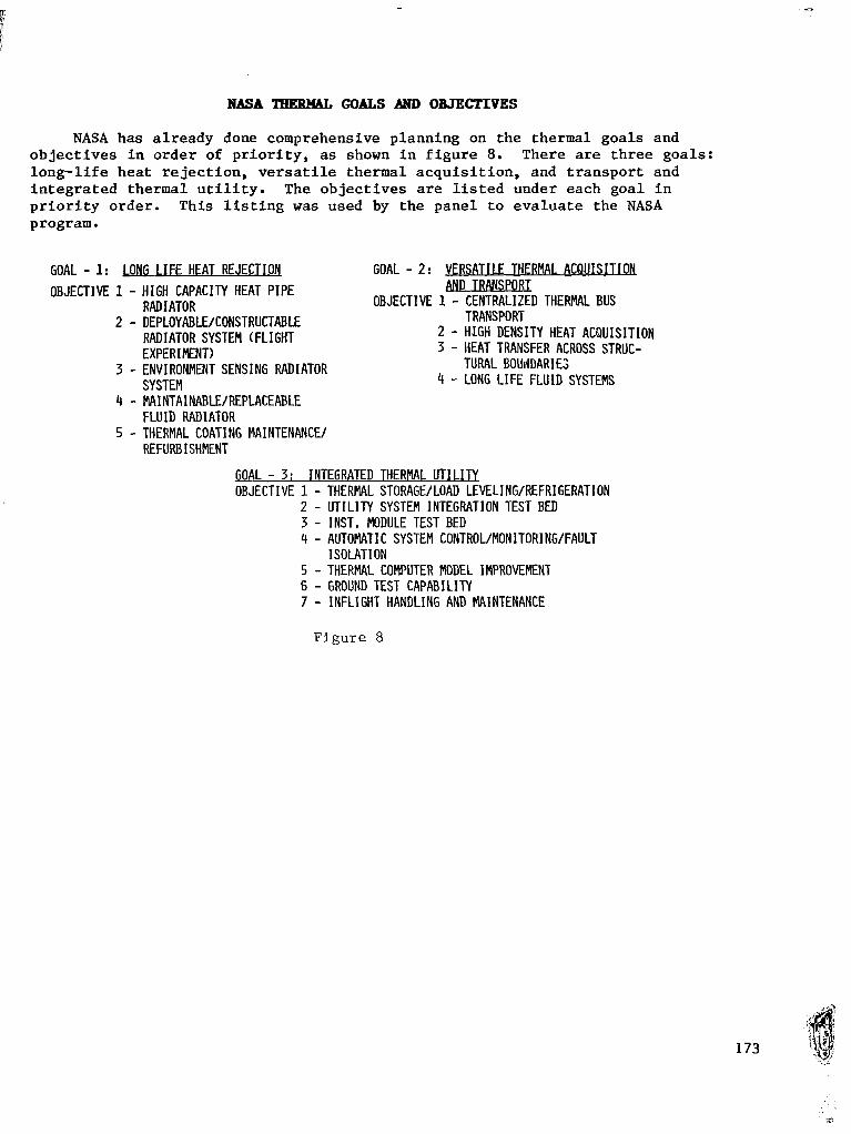
NASA TEERMAL GOATS AND OBJECTIVES
NASA has a l ready done comprehensive planning on the thermal goals and o b j e c t i v e s i n o r d e r of p r i o r i t y , as shown i n f i g u r e 8 . There are three goa ls : l ong- l i f e hea t r e j ec t ion , versati le thermal acquis i t ion , and t ranspor t and i n t e g r a t e d t h e r m a l u t i l i t y . The ob jec t ives are l i s t ed unde r each goa l i n p r i o r i t y o r d e r . T h i s l i s t i n g was used by the pane l t o eva lua te t he NASA program.
GOAL - 1: LONG I IFE HEAT REJECTION GOAL - 2: VERSATILE THERMAL ACQUISITIOB OBJECTIVE 1 - HIGH CAPACITY HEAT PIPE -
RAD I ATOR
RADIATOR SYSTEM (FLIGHT EXPERIMENT)
SYSTEM 4 - LONG LIFE FLUID SYSTEMS
OBJECTIVE 1 - CENTRALIZED THERMAL BUS 2 - DEPLOYABLE/CONSTRUCTABLE TRANSPORT
2 - HIGH DENSITY HEAT ACQUISITION 3 - HEAT TRANSFER ACROSS STRUC-
3 - ENVIRONMENT SENSING RADIATOR TURAL BOUdDARIE;
4 - MAINTAINABLE/REPLACEABLE FLU ID RAD I ATOR
REFURBISHMENT 5 - THERMAL COATING MAINTENANCE/
GOAL - 3: INTEGRATED THERMAL U T I L U OBJECTIVE 1 - THERMAL STORAGULOAD LEVELING/REFRIGERATION
2 - UTILITY SYSTEM INTEGRATION TEST BED 3 - INST, MODULE TEST BED 4 - AUTOMATIC SYSTEM CONTROL/MONITORING/FAULT
ISOLATION 5 - THERMAL COMPUTER MODEL IMPROVEMENT 6 - GROUND TEST CAPABILITY 7 - INFLIGHT HANDLING AND MAINTENANCE
F i g u r e 8

INDUSTRY EVATJIATION
The cr i t er ia used in the technical evaluation are l i s t e d in f igure 9 . The bottom line in appraising the plan was whether the technology l eve l being sought is affordable, too advanced, too high risk, or requires too much development.
o CRITERIA - - PROGRAMFIAT I C
DOES I T M E T UI4IQUE SPACE STATION REQL!IREPIENTS? - TECH14 I C,IL
WILL I T KORK? - SCI!EDULE
WILL I T BE OM TIYE? - 2ELIABILITY/SAFETY
I S I T INHERENTLY RELIABLE? - COST
WILL I T BE AFFORDABLE?
Figure 9
174

WBCLT ARE TEE GOOD POINTS?
The c r i t i q u e of the p lan ind ica ted a number of good p o i n t s , p a r t i c u l a r l y t h e o v e r a l l g o a l s and ob jec t ives ( f ig . 10). The development of high capaci ty hea t p ipe r ad ia to r s , which is a new technology, was s p e c i f i c a l l y good. To backtrack, when t h e e f f o r t was i n i t i a t e d 3 years ago, heat pipe performance was on the o rder of 5,000 t o 10,000 wat t - inches for ex t ruded type hea t p ipes tha t cou ld be mass produced for a l a r g e s t a t i o n . The goa l was 1 mi l l i on watt- inches, which is two o rde r s of magnitude better. These are the k inds of improvements t h a t are being sought in the thermal program. New technology is c a l l e d f o r i n t h i s i n s t a n c e . The cur ren t Shut t le t echnology is not appropr ia te f o r t h e s p a c e s t a t i o n . It would be an extremely brute force way t o s a t i s f y t h e space s t a t ion needs . The p a y o f f s i n t h e new technology are good. The r a d i a t o r is a tremendous improvement i n r e l i a b i l i t y and m a i n t a i n a b i l i t y f o r a r e l a t i v e l y modest front-end cost. To s a t i s f y u s e r s , which is the ob jec t ive of the space s t a t i o n , t h e two-phase system is f a r s u p e r i o r t o a pumped fluid-loop system. The plan also recognized the importance of p rov id ing t he ana ly t i ca l t oo l s , ground test beds, and f l i g h t tests to deve lop t h i s new technology.
0 GOALS AND OBJECTIVES ARE RIGHT ON - IMPORTANT ISSUES - PRIORITY
0 PLAN PROVIDES FOR HIGH LEVERAGE NEW TECHNOLOGY DEVELOPMENT PAYOFF
- LONG L I F E HEAT REJECTION, , , , , ,H IGH BENEFIT FOR COST - VERSATILE THERMAL ACQUISITION , . ,MODULARITY, GROWTH, F L E X I B I L I T Y
AND TRANSPORT - INTEGRATED THERMAL U T I L I T Y , . . . ,AUTOMATION, ECONOMY
0 PLAN RECOGNIZES NEED FOR ANALYTICAL TOOLS 0 PLAN INTEGRATES NEW TECHNOLOGY-TEST BED 0 PLAN PROVIDES FOR FLIGHT TEST OF CRITICAL COMPONENTS
Figure 10
175
I
WBAT WEBE TEE BAD POINTS?
The few bad po in t s p re sen ted i n f i gu re 11 are i n t e r r e l a t e d and cannot be taken ou t of context . The p lan is underfunded i n t h e n e a r term. Since the system is t o t a l l y new, more paral le l development is needed i n t h e e a r l y s t a g e s , when i t is, n o t p o s s i b l e t o commit t o one approach. The p a r a l l e l e f f o r t s are only a small percentage of t he main e f f o r t and are cons t ra ined by funding. F l i g h t test t a sks are not scheduled to support a phase C/D start i n 1987. I f t h i s d a t e were 1992 or 1993, the plan as presented would be f i n e . The reason f o r t h e i n c o n s i s t e n c y between need d a t e and the p lan as shown i s funding. The need f o r early f l i g h t tests is emphasized. Since some bas i c mechanisms work b e t t e r on the ground than i n space, h igh capac i ty hea t p ipes and two-phase hea t t ransport loops must be t e s t e d i n t h e real environment.
I n summary, i t is a h i g h r i s k program only i n t h e c o n t e x t of t h e e a r l y need da te r e l a t ive t o t he cu r ren t budge t l imi t a t ions . The f l i g h t test schedule does not support the need da te ; t he re f o re , t he cos t r i sk is high because problems w i l l occur downstream that w i l l be expens ive to cor rec t . Also, t he funding is l imi t ing t he pa ra l l e l deve lopmen t , which adds a l i t t l e t e c h n i c a l r i s k .
0 UNDERFUNDED AND POORLY TIME PHASED
0 INSUFFICIENT PROVISION FOR PARALLEL DWELOPMENT OF CRITICAL TECHNOLOGIES - H M T REJECTION SYSTEM - THERMAL TRANSPORT LOOP
0 TASKS NOT SCHEDULED TO SUPPORT PHASE C/D START I N 1987
0 EARLY FLIGHT TEST OF TWO-PHASE FLUID SYSTEMS NOT INCLUDED
0 SUMMARY: HIGH RISK PROGRAM - SCHEDULE - COST -TECHNICAL
Figure 11
176

There is not enough emphasis on advanced heat re ject ion concepts ( f i g . 1 2 ) . NASA has been looking a t body mounting for some of the hea t r e j ec t ion sys t ems i n s t ead of a t cons t ruc t ab le , l a rge r ad ia to r s , bu t t h i s does not appear in the p lan . It is l i k e l y t h a t t h e e a r l y space s t a t i o n w i l l have some body-mounted r a d i a t o r s . The h a b i t a t may have its own r a d i a t o r and be the s t o r m c o l l a r , if the main system goes out for any reason. The crew could s u r v i v e i n t h e h a b i t a t u n t i l repair or rescue. NASA is a l s o p a r t i c i p a t i n g i n some advanced concepts (such as the d rop le t r ad ia to r ) bu t t h i s t echno logy does not appear in the p lan .
I n t h e h e a t t r a n s p o r t area, two-phase flow is a major area f o r a d d i t i o n a l i n v e s t i g a t i o n , b o t h a n a l y t i c a l and experimental . The proper emphasis f o r unders tanding the bas ics of two-phase flow is not in the cur ren t p lan . Funding on the user-or iented devices should be d e l a y e d u n t i l more s p e c i f i c space s t a t ion needs are i d e n t i f i e d .
The key area i d e n t i f i e d was the need f o r ear ly f l ight development tests because of the new technology. Fl ight tests and supporting ground tests would v e r i f y computer models required for space station thermal sys tem design opt imizat ion.
0 LONG L I F E HEAT REJECTION - ADD BODY MOUNTED HEAT REJECTION - ADD ADVANCED RADIATOR CONCEPTS
0 THERMAL ACQUISITION AND TRANSPORT - ADD EFFORT TO BETTER UNDERSTAND 2-PHASE FLOW I N ZERO G BY
ANALYSIS AND TEST
NEED IDENT I F I ED - DELAY DEVELOPMENT OF SOME SPEC1 F IC COMPONENTS UNTIL SPACE STATION
0 INTEGRATED THERMAL U T I L I T Y - ADD EARLY FLIGHT DEVELOPMENT TESTS
-- SUPPORT GROUND TEST -- VERIFY COMPUTER MODELS
Figure 12
177
Industry-funded tasks are l i s t e d i n f i g u r e 13, but are at a r e l a t i v e l y low level. The combined indus t ry IR&D effor t probably does not exceed NASA's funded work i n thermal technology. Company IR&D w i l l follow the approved program, so un t i l t he space s t a t ion f i rms up more, t h i s e f f o r t s h o u l d n o t be counted on f o r any ex tens ive input .
0 SPACE ASSEMBLY SIMULATION
0 ROTATING RADIATORS
0 COAT I NG MA I NTENANCE
0 TWO-PHASE HEAT TRANSFER/LOOP CONEFTS
0 HIGH CAPACITY tlEAT PIPES
Figure 13
178

From the evaluation of the government-funded work and the industry IR&D activity, the technology readiness of heat pipe radiators, two-phase loops, and components is assessed in figure 14. The key message is that many of the systems need a flight test verification because they are gravity sensitive and almost all new thermal systems need a prototype test in the operative ground environment (a thermal vaccuum chamber).
O R A D I A T O R
- HIGH CAPACITY HEAT P I P E - RADIATOR/LOOP INTERFACE - COAT I HG MA I MTENANCE -. SPACE ASSEMBLY PROCEDURES
o m - TWO PHASE TtiERMAL ELIS - INTERFACES - AUTOMATED CONTROL/FAULT DETECTION - ON ORBIT ASSEMBLY/MAINTENANCE
o COMPOWFNTS - D I SCONNECTS - SWIVELS - THERMAL STORAGE
N!N 4 4 2 2
NEEDED 7 5 7 7
F i g u r e 14
179

FLIGHT TEST REQUIREMENTS
F l i g h t tests are mandatory in the thermal t echnology area ( f i g . 15). Both t h e r a d i a t o r and thermal bus have t o be des igned fo r ze ro g rav i ty and they have to be t e s t ed i n ze ro g rav i ty t o p rove t ha t t hey r ea l ly work. There are a l s o a number of assembly tasks that can be done t o a n e x t e n t i n s i m u l a t o r s b u t a t some poin t i t must be demons t r a t ed t ha t t he en t i r e sys t em can r ea l ly go toge the r and func t ion i n o rb i t .
Cur ren t ly , t he p l an is missing a Shu t t l e ze ro -g rav i ty test bed program that backs up the ground test beds i n t h e p l a n . The tes t would have to be conducted on a non-interference basis . Al though the Shut t le manifest is f u l l f o r many years (cannot bump another experiment), i t should be p o s s i b l e t o u s e t h e RMS clearance envelope on f l i g h t s where a second RMS is not f lown. This envelope is roughly a 15-inch-diameter c i rc le t h a t is reserved for the RMS and runs the length of the cargo bay s i l l l i n e . The r a d i a t o r and t ranspor t loop experiments can be packaged t o f i t w i t h i n t h a t e n v e l o p e . In o r d e r f o r t h i s t o happen i n t h e r e q u i r e d time frame, work needs to be s ta r ted immedia te ly on de f in ing a standard instrumentation and interface package. For example, a s p e c i f i c number of temperature measurements, the power l e v e l , and t h e S h u t t l e heat load limits must be def ined.
Quick response procedures should be i n s t i t u t e d f o r t h e e x p e r i m e n t s . Sa fe ty of f l i g h t s h o u l d be the only requirement. The h i s t o r y on Apollo and o t h e r programs is c u r r e n t l y i n h i b i t i n g t h e i n n o v a t i o n of new technology. This h i s to ry e s t ab l i shed t ha t expe r imen t s be engineered and t e s t e d on the ground to accura te ly p red ic t the E l ight per formance . To reduce development time and c o s t , t h i s h a s to change. Experiments should be t r e a t e d as real experiments; some w i l l work, some w i l l not work (wi l l no t p rovide the expec ted da ta ) , bu t a l l must be s a f e t o f l y . And the experiments should be conducted on a s t r i c t , non- in te r fe rence bas i s wi th the main Shut t le payload to assure tha t a number of experiments can be flown.
FLIGHT TESTS ARE MANDATORY
0 RADIATOR - G SENSITIVE
0 THERMAL BUS - G SENSITIVE
0 SPACE ASSHIBLY/MAINTENANCE TECHNIQUES - INTEGRATE PROCEDURE (ASTRONAUT/RMS/ASSEMBLY TOOLS)
APPROACH
0 ESTABLISH SHUTTLE ZERO-G TEST BED PROGRAM - USE RMS CLEARANCE ENVELOPE - STANDARD INSTRUMENTATION/FLU I D INTERFACES - INSTITUTE QUICK RESPONSE PROCEDURES - CONDUCT EXPERIMENTS ON NON-INTERFERENCE BASIS
Figure 15
180

SPACE CX3NSTRKJCTABLE BZGH-CAPACITIC RADIATOR FLIGET VERIFICATION: TBERHAL EXPERIMENT
An example of a radiator f l ight verif icat ion test is i l lustrated in figure 16. Electrical heat would simulate the two-phase loop heat load that would go into the radiator. The radiator would be mounted along the s i l l l i n e and radiate its heat into space.
F i g u r e 16
18 1

HEBT TBANSFEB LOOP FLIGHT TEST ARTICLE
A sketch of a typical heat transfer loop fl ight test article is shown i n figure 17 .
CONDENSER/HEAT REJECTION INTERFACE 7
- PUMP ASSEMELY
LINES
Figure 17
182
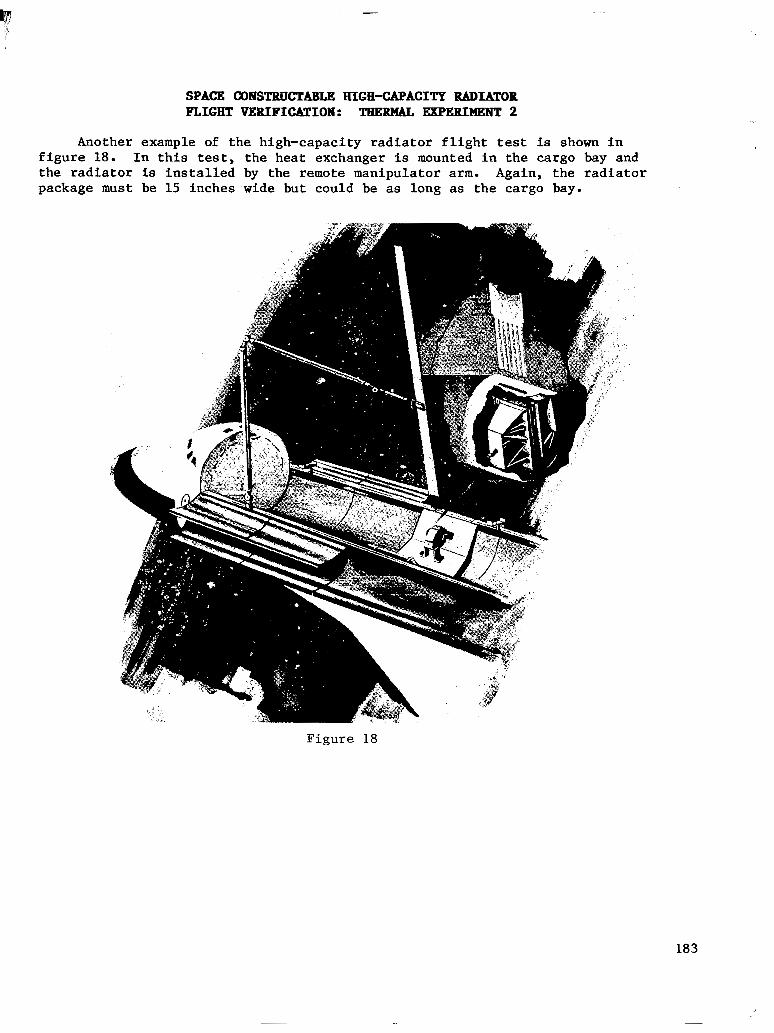
SPACE 0oBSTBUCTABI.E HIGH-CAPACITY RADLATOB FLIGHT VERIFICATION: THERMAL EWEEIUENT 2
Another example of t he h igh -capac i ty r ad ia to r f l i gh t tes t is shown i n f i g u r e 18. I n t h i s test, the heat exchanger is mounted i n t h e c a r g o bay and t h e r a d i a t o r is i n s t a l l e d by the remote manipulator arm. Again , the rad ia tor package must be 15 inches wide but could be as long as the cargo bay.
Figure 18
183

I
THERMAL BUS TW-PHBSE FLOW/EEAT' TRANSFER EVALUATION
More extensive experiments could be conducted on a thermal bus, either hard-mounted in the Shuttle cargo bay or deployable as a free-flyer (fig. 19). These tests should be near-term, with flight experiments in 1985 or 1986 if the technology need date remains 1987.
Figure 19
184
CONCLUSIONS
The panel concluded that the NASA plan is very well conceived ( f ig . 20). NASA is proceeding wi th inherent ly re l iab le approaches for the space s ta t ion , as opposed to ove rk i l l ( r e l i ab i l i t y w i th t r emendous r edundancy) . Ex i s t ing f lu id - loop r ad ia to r s would r e q u i r e i s o l a t i o n v a l v e s and sensors and l a r g e redundant pumps. The pumps would have to be very e f f ic ien t and therefore would be designed with l i t t l e margin. With the new sys tems, the rad ia tor is a very fa i l - sa fe des ign wi th a loss of only a percent o r two of h e a t r e j e c t i o n capaci ty each time a hea t p ipe is punctured. The flow rates in t h e two-phase system are so low (small pumps with low power l e v e l s ) t h a t u s i n g s e v e r a l pumps i n parallel would provide almost no penal ty . The system would be inhe ren t ly r e l i a b l e .
Bold approaches are being taken and the pane l agreed wi th th i s . Money should not be invested for modest improvements i n performance. Orders of magnitude improvement in performance can be made across the board in the thermal system. This approach can be taken because there I s a clear a l t e r n a - t i v e p o s i t i o n , t h e f l u i d l o o p , which w i l l work. Rowever, t h i s is no t t he bes t approach, and research should proceed as €ast as poss ib le to deve lop a b e t t e r sys tem.
I n t h e way of s p e c i f i c c r i t i q u e s , t h e f l i g h t tests which are now shown t o be i n 1988 and 1989 c lear ly have a 1987 need da te . The on ly f eas ib l e way t o do t h i s is to ded ica t e a zero-gravi ty test bed concept. To ge t the test bed and the subsequent f l igh t tests ready, both increased funding and much ear l ier funding are needed. The NASA plan shows a s t r a i g h t - l i n e i n c r e a s e from a very low leve l th i s year to reasonable funding in 1988 and then a p la teau in funding fo r s eve ra l yea r s . Th i s is not cons is ten t wi th a 1987 need. The funding has to increase immediately and be r e l a t ive ly h igh i n 1984 and 1985. To go t o zero-gravi ty test beds, the ground test bed program must be a c c e l e r a t e d t o s u p p o r t t h o s e f l i g h t t e s t s .
Another incons is tency in the p lan involves the i s sue of s u r v i v a b i l i t y . I n t h e c u r r e n t e i g h t a r c h i t e c t u r e s t u d i e s on t h e s p a c e s t a t i o n , one of the main o b j e c t i v e s is to de te rmine how the A i r Force (or other m i l i t a r y service) might use a space s t a t ion . The thermal p lan d id no t explore the surv ivabi l i ty of these systems. However, s ince they are inhe ren t ly more r e l i ab le , t hey are inhe ren t ly more s u r v i v a b l e . S t i l l , more survivable approaches should be pu r sued fo r spec ia l mi s s ions o r t o enhance t he t o t a l space s t a t ion . Las t ly , ear ly-on ( in the next few years) s t rengthening of some para l le l technology pa ths i s encouraged.
.. .
185

CONCLUSIONS
0 NASA PLAN I S WELL CONCEIVED - INHERENTLY RELIABLE/MAINTAINABLE DESIGN CONCEPTS - BOLD APPROACHES FOR ORDER OF MAGNITUDE IMPROVEMENT - CAN FALL BACK TO CURRENT TECHNOLOGY AT LATE DATE
0 INDUSTRY CRITIQUE - FLIGHT TESTS NEED TO BE CONDUCTED 2-3 YEARS EARLIER - NE€D INCREASED FUNDING ( 3 TIMES) - NEED EARLIER FUNDIKG (FY84 & 85) - TEST BED A C T I V I T I E S MUST BE ACCELERATED AND EXPANDED - SURVIVABILITY FOR AIFl MISSIONS SHOULD BE CONSIDERED - STRENGTHEN PARALLEL TECHNOLOGY PATHS
186
Figure 20
~
1. Report No. 3. Recipient's C a t a l o g No. 2. Government Accession No.
NASA CP-2293 4. Title and Subtitle 5. Report Date
February 1984 SPACE STATION TECHNOLOGY - 1983 6. Performing Organization Code
506-64-13 7. Author(s1 8. Performing Organlzation Report No.
Robert L. Wright and Cathy R. Mays, Edi tors L-15732 10. Work Unit No.
9. Performing Organization Name and Address
NASA Langley Research Center Hampton, Virginia 23665
11. Contract or Grant No.
13. Type of Report and Period Covered
Conference Publication 12. Sponsoring Agency Name and Address
National Aeronautics and Space Administration Washington, DC 20546
14. Sponsoring Agency Code
I 15. Supplementary Notes
16. Abstract
This publication i s a compilation of the panel summaries presented a t t he Space Stat ion Technology Workshop held a t the National Conference Center, Williamsburg, Virginia, March 28-31, 1983. The object ive of the workshop w a s t o a i d t h e Space S ta t ion Technology Steering Committee i n d e f i n i n g and implementing a technology development program to support the establishment of a permanent human presence in space. This compilation w i l l provide the par t ic ipants and their organizat ions with the information presented a t t h i s workshop i n a referenceable format. This infor- mation w i l l e s t ab l i sh a s tepping s tone for users o f space station technology to develop new technology and p lan fu ture t asks .
7. Key Words (Suggested by Author(s)) 18. Distribution Statement
Space s t a t i o n Space station technology Space s ta t ion des ign
Unclassified - Unlimited
Manlsystems technology Space station systems technology
Subject Category 15 9. Security Classif. (of this report)
A0 9 193 Unclassified Unclassified 22. Rice' 21. NO. of Pages 20. Security Classif. (of this p a g e )
* For sale by the National Technical information Service, Springfield, Virginia 22161 NASA-Langley, 1984

National Aeronautics and Space Administration
Washington, D.C. 20546 Official Business Penalty for Private Use, $300
SPECIAL FOURTH CLASS MAIL BOOK
Portage and Fees Paid National Aeronautics and Space Administration NASA451
POSTMASTER: If Undeliverable (Section 158 Postal Manual) Do Not Return
. . . . .. . . , - . - ..". .