nasa · empirical or semiempirical correction factors; as examples, the correction factor ... the...
TRANSCRIPT
NASA Technical Memorandum 83198
An Approximate Analytical Methodfor Vortex-Lift and Centerof Pressure on the Slender Wing
Yin Xieyuan
DECEMBER 1981
Translation from Acta Aeronauticaet Astronautica Sinica, Volume 1,Number 1, 1980> pp. 1-6
NASA
https://ntrs.nasa.gov/search.jsp?R=19820005172 2018-08-21T17:43:00+00:00Z

NASA Technical Memorandum 83198
An Approximate Analytical Methodfor Vortex-Lift and Centerof Pressure on the Slender Wing
Yin XieyuanScience and Technology University of ChinaHofei, China
Translated byGrace C. LiuLangley Research CenterHampton, Virginia
Translation from Acta Aeronauticaet Astronautica Sinica, Volume 1,Number 1, 1980, pp. 1-6
NASANational Aeronauticsand Space Administration
Scientific and TechnicalInformation Branch
1981

ABSTRACT
This paper presents a simplified approximate analytical method for predictingvortex-lift, and its center of pressure on the slender wing at high angle of attack,and proposes two empirical correlations. In comparison with other methods and exper-imental data, this method provides good accuracy and is suitable for preliminarydesign.
In recent years, interest in the high angle of attack nonlinear aerodynamics hasincreased considerably. This interest has led to studies of the separated vortexflow as an important nonlinear effect on flow characteristics: the theory of growthand breakdown of the separation vortex; the influence of vortex separation on aero-dynamic characteristics related to aircraft; and how to utilize and control the sep-aration vortex effectively. This is a very important and active research subject inaeronautics.
Currently, many theoretical methods have been developed in calculating the aero-dynamic characteristics of leading-edge vortex separation, but they primarily reliedon high speed computers. The object of this paper is to seek an approximate analyt-ical method that can provide a fast estimate for various different wing planforms-This method will be extremely useful in the preliminary design stage for designers.Several years ago, the author suggested a simple method for the calculation of tipvortex-lift. Based upon the fundamental work in reference (1) this paper derived aformula for vortex- lift and its center of pressure. For the convenience of engi-neering estimation, two empirical correlation formulas were given as well. Recently,Purvis derived a similar analytical method. A comparison of references (1) and(2) shows that the results of reference (2) are achieved.
1. ANALYSIS
The Polhamus "leading-edge suction analogy" theory compares well with experi-mental work and has been widely used in engineering. The following expressions forvortex-lift coefficient come from that theory:
2C = K sin a cos a/cos ALV,LE XT
KKv,
where K_, K-. T are the constants for the potential-flow lift coefficient and theleading-edge thrust coefficient, respectively. A is the leading-edge swept angle.An important advantage of this theory is that one can study the nonlinear effect byusing the potential flow theory. In application, equation (1) proves to be simpleand reliable, but it provides only the total lift. If one desires the potential flowof the vortex-lift distribution, then panel or kernel function methods must be usedto compute the leading-edge suction distribution. Nevertheless, this is not the

intent of this paper. In order to compute the vortex-lift and its center of pres-sure, we assume, as shown in figure 1, that the vortex-lift in the inboard wing sec-tion E«oE is equivalent to the vortex-lift for the isolated wing section E..OE. Inother words, we consider that the leading-edge-suction analogy is not only applicableto the whole wing planform but is also applicable to each individual inboard wingsegment. Therefore,
C (y) = C' (y)S'(y)/S (2)V,LE r̂,LE W
2C' (y) = K' _(y) sin a cos a/cos A (3)V,LE '
K̂ (y) = K̂ (y)
where the primed variables are for the inboard wing E^oE. S'(y) and S denotethe area of inboard wing and the area of whole wing, respectively.
In the calculation of tip-vortex-lift, one can further let the tips AB andA.jB.j extend outboard an angle e such that tips AB and A^B^ become part of theleading edge. Applying the suction analogy to the whole wing and inboard wing seg-ment separately, one can obtain the total thrust and the thrust of the inboard wingsegment. When e ->• 0, it gives the tip-votex-lift (see fig. 1).
2C = K_T sin a cos a (5)Jj,7 _„ v,bb
KV,SE - ̂N,T/tan E)AB' * V;
In addition, by the definition of vortex-lift distribution
C_ (y) = f- fYc(y)c (y) dy (7)LV,LE w Jo V
where c(y) is the local chord length and c (y) is the sectional vortex-liftV
coefficient. Substituting equations (2) and (3) into equation (7) yields
i (y) = j |- K^ T(y)S'(y)/cos A sin2 a cos a (8)

Inserting equations (5) and (6), one obtains the tip-vortex-lift
or
= lim"V,SE e->0
A/*\V J b/2
' (y)S'(y)/tan el dy sin a cos a' ̂ — ' I
(9)
T,SE
dS'
w
where b is span and cfc is wing tip chord length. Equation (10) has been derivedin reference (2). Similarly, one can obtain the center of pressure of the leadingedge and the tip-vortex-lift as
b/2
r w r V,T J LE
0
r|X
e->0dy T e] dy
(11,
(12)
respectively, where c is wing root chord length; XTE is the chordwise distancemeasured from the leading edge; x£E = x - x^. . is the chordwise distance measuredfrom the wing tip leading edge. Equations (9) 'to (12) are the general expressionsfor the tip-vortex-lift and its center of pressure. From the expression, one can seethat they are functions of potential-flow lift and the geometric configuration.
For slender wing, according to Jones' slender body theory, Kp=-^A, K V _ = - ? A .Substituting into equation (8) yields equation (13):
(y) = ity/cos A sin a cos aV
(13)
From the above equation, vortex-lift distribution obtained from the slender-bodytheory is a linear distribution; it agrees with conic flow assumptions. Figure 2presents a comparison of the sectional vortex-lift and inboard-wing-section vortex-lift with reference (2). It shows very good agreement.
Substituting and Ky T into equation (9) or (10), one obtains
= iiAl — a cos a
,,4)
tc \ K— ) — sin a cos abJ™
*Translator's note: error in original text.

Equation (14) is obtained under the slender-body theory; one can get better resultsby using more accurate values of Kp. Following the above equation KV SE = n for arectangular wing with a small aspect ratio, which agrees with Lamar's results inreference (4). Figure 3 compares the results obtained from equation (14) with
Lamar's (ref. (4)) and Purvis' (ref. (2)) results at Kp = 2-nA/(\JA + 4 + 2J.From the figures, it is shown that our results agree quite well with Lamar's.Purvis" results seem too high.
Substituting Kp and K^ T into equations (11) and (12), yields
(Triangular wing/delta wing) (15)
(Trapezoidal wing) (16)
(17)
where c1 is the wing root chord length corresponding to the trapezoidal wing
leading edge, cr = 2 ̂ an ̂ *
From equations (15), (16), and (17), one can see that center of pressure of theleading-edge vortex-lift and tip-vortex-lift obtained from the slender-body theoryagrees with the existing results in the literature. Furthermore, one discovers thatthe center of pressure of the leading-edge vortex-lift and the center of pressure oftip-vortex-lift for a trapezoidal wing can be obtained separately. This gives thetheoretical basis for the following empirical corrections.
2. EMPIRICAL CORRECTIONS
Experiments proved that the "suction analogy" theory is only applicable for acertain range of angle of attack and aspect ratio. In order to extend the applica-bility of this theory to a wider range, many researchers have introduced differentempirical or semiempirical correction factors; as examples, the correction factorK* for the leading-edge vortex-lift for a delta wing in reference (5), and theimprovement factor K-, „„ of tip-vortex-lift in reference (6), etc. This paper alsoprovides the correction formula.
1. Center of pressure correction.
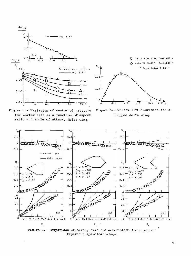
From equation (15), under the conic flow assumption, the center of pressure oftip-vortex-lift is located at 2/3 root chord. However, the physical vorticitystrength does not quite have a conic distribution, especially near the trailingedge. As angle of attack increases, the vortex core moves inboard. Following theexperimental data analysis, the center of pressure for a delta wing is
j£
V/LE = -| - 0.3729/tan A (18)c 3r
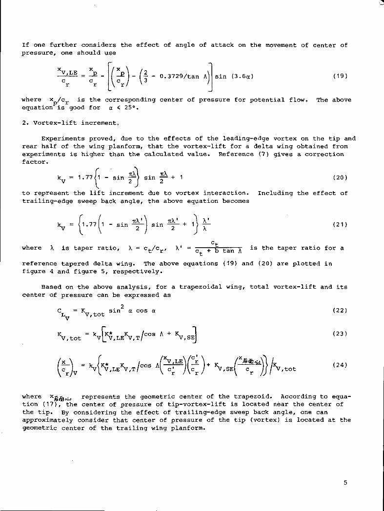
If one further considers the effect of angle of attack on the movement of center ofpressure, one should use
XV,LE = *£C Cr r
- (~ - 0.3729/tan A sin (3.6tt) (19)
where xD/cr is the corresponding center of pressure for potential flow. The above
equation is good for a < 25°.
2. Vortex-lift increment.
Experiments proved, due to the effects of the leading-edge vortex on the tip andrear half of the wing planform, that the vortex-lift for a delta wing obtained fromexperiments is higher than the calculated value. Reference (7) gives a correctionfactor.
kv = 1.77/1 - sin |M sin ̂ + 1 (20)
to represent the lift increment due to vortex interaction. Including the effect oftrailing-edge sweep back angle, the above equation becomes
i )i -i-il i • rcX' \ . itX' , A \' . 4.k_7 = < 1.77 1 - sin -— — sin — r— + 1 > 7~~ (21 )•V ^ \ 2 I 2 J X
ctwhere \ is taper ratio, \ = c./c , X1 = - — + K tan A ^s the taPer ratio for a
reference tapered delta wing. The above equations (19) and (20) are plotted infigure 4 and figure 5, respectively.
Based on the above analysis, for a trapezoidal wing, total vortex-lift and itscenter of pressure can be expressed as
2. .tot
K „ . . sin a cos a (22)V,
Vtot - kv(5,LEVT/cos A + VSE] (23)
where xjgi&io; represents the geometric center of the trapezoid. According to equa-tion (17), the center of pressure of tip-vortex-lift is located near the center ofthe tip. By considering the effect of trailing-edge sweep back angle, one canapproximately consider that center of pressure of the tip (vortex) is located at thegeometric center of the trailing wing planform.

3. CONCLUDING REMARKS
Applying current methods to a set of trapezoid wings, the results compare quitewell with experiments as shown in figure (6).
This method can be extended to the calculation of vortex-lift and its center ofpressure for a wing-body combination. It is also not difficult to apply to a wingwith a cranked leading edge such as a straked wing.
The compressibility effect can be taken care of by the Prandlt-Gothert law.
From the equations obtained in this paper, one can find a best combination ofsweep back angle, taper ratio, and aspect ratio to achieve maximum vortex-lift. Thismethod is suitable for preliminary design.
The author expresses his thanks to Professor Tung for his continued support andfor reading the manuscript.
Langley Research CenterNational Aeronautics and Space AdministrationHampton, VA 23665November 6, 1981
REFERENCES*
(1) Yin Xieyuan: An Approximate Estimate Method for Vortex-Lift on an Arbitrary WingPlanform with Small Aspect Ratio. The Science and Technology University ofChina, Study in Mechanics, No. 4, Apr. 1976.
(2) Purvis, J. W.: Analytical Prediction of Vortex Lift. AIAA Paper 79-0363,Jan. 1979.
(3) Polhamus, Edward C.: A Concept of the Vortex Lift of Sharp-Edge Delta WingsBased on a Leading-Edge Suction Analogy. NASA TN D-3767, 1966.
(4) Lamar, John E.: Extension of Leading-Edge-Suction Analogy to Wings With sepa-rated Flow Around the Side Edges at Subsonic Speeds. NASA TR R-428, 1974.
(5) Mendenhall, Michael R.; and Nielsen, Jack N.: Effect of Symmetrical Vortex Shed-ding on the Longitudinal Aerodynamic Characteristics of Wing-Body-Tail Combi-nations. NASA CR-2473, 1975.
(6) Lamar, John E.: Some Recent Applications of the Suction Analogy to Vortex-LiftEstimates. Aerodynamic Analyses Requiring Advanced Computers, Part II, NASASP-347, 1975, pp. 985-1011.
(7) Huang, T. L.: Method of Computation for Aerodynamic Characteristics in Longitu-dinal Plane for a Projectile at Large Angle of Attack. The Science and Tech-nology University of China, Internal Report, Dec. 1976.
(8) Kirby, D. A.: Low-Speed Wind-Tunnel Measurements of the Lift, Drag and PitchingMoment of a Series of Cropped Delta Wings. R. & M. No. 3744, British A.R.C.,Nov. 1972.
*Editorial note: Titles have been added for references (3) through (6) andrefer-ence (8), which was used on a figure, has been added to list.

s'(y)
Figure 1.- Geometric relationship and configuration for
tip-vortex-lift calculation.
V,LE
1.0
0.5
1.5
1.0
0.5
This paper
ref. (2)
H(rO •- ref . (2) eq. (28)
i
0.5 i.o
H ( n )
0.5 i.o n
Figure 2.- vortex-lift distribution:
A comparison between this paperand ref. (2) .
/,SE
4.0
3.6
3.2
2.8
2.4
2.0
1.6
1.2
0.8
0.4
0
ref.(4) 3-D result*
ref. (2) eq. (52)
This paper & ref.(4)
* Translator's note
0.4 0.8 1.2 1.6 2.0 2.4 2.8 3.2 A
Figure 3.- Comparison of Ky gE
for rectangular wing.
eq. (18)
\J . -J • I 1 I
V,LE 0 0.5 1.0 1.5
XOZ!iCH-exp. values
eq. (19)
0.60
0.55 -
ARC R & M 3744 ( r e f . ( 8 ) ) *
NASA TR R-4.28 ( r e f . ( 4 ) ) *
* Translator's note
1.4 -
0.50 i i i i i 10 5 10 15 20 25 a
Figure 4.- Variation of center of
1.2 -
1.00 0.2 0.4 0.6
ure 4.- Variation of center of pressure Figure 5.- Vortex-lift increment for
for vortex-lift as a function of aspect cropped delta wing,
ratio and angle of attack, delta wing.
m
0.2
0
-0.2
D
0.8
0.6
0.4
0.2
OC
ref. (4)
This paper
0 0.20.40.60.81.01.21.4 0 0.20.40.60.81.01.21.4 0 0.20.40.60.81.01.21.4
"L "L "L
Figure 6.- Comparison of aerodynamic characteristics for a set oftapered trapezoidal wings.
1. Report No.
NASA TM-831982. Government Accession No. 3. Recipient's Catalog No.
4. Title and SubtitleAN APPROXIMATE ANALYTICAL METHOD FOR VORTEX-LIFT ANDCENTER OF PRESSURE ON THE SLENDER WING
5. Report Date
December 19816. Performing Organization Code
530-04-13-01
7. Author(s)
Yin XieyuanScience and Technology University of China
8. Performing Organization Report No.
L-14848
10. Work Unit No.
9. Performing Organization Name and Address
NASA Langley Research CenterHampton, VA 23665
11. Contract or Grant No.
12. Sponsoring Agency Name and Address
National Aeronautics and Space AdministrationWashington, DC 20546
13. Type of Report and Period Covered
Technical Memorandum
14. Sponsoring Agency Code
15. Supplementary Notes
Translated by Grace C. Liu, Langley Research Center,Astronautica Sinica, Volume 1, Number 1, 1980, pp. 1
from Acta Aeronautics et-6.
16. Abstract
A -simplified approximate analytical method for predicting vortex-lift and center ofpressure on slender wings is presented. Two empirical corrections are proposed. Themethod is compared with experimental data and is shown to provide accurateestimates. (Translator)
17. Key Words (Suggested by Author(s) I
Center of pressureVortex-liftSlender wings
18. Distribution Statement
Unclassified - Unlimited
Subject Category 01
19. Security Oassif. (of this report)
Unclassified
20. Security Classif. (of this page)
Unclassified
21. No. of Pages
10
22. Price
A02
For sale by the National Technical Information Service, Springfield, Virginia 22161
NASA-Langley, 1981