nasa · pdf filedensity on plasma sprayed tbc durability is a result of the strain tolerance...
TRANSCRIPT

SS %1
NASA Technical Memorandum 103708
Thermal Barrier CoatingEvaluation Needs
William J. Brindley and Robert A. MillerLewis Research CenterCleveland, Ohio
Prepared for theConference on Nondestructive Evaluation of Modern Ceramicscosponsored by the American Ceramic Society and the AmericanSociety of Nondestructive TestingColumbus, Ohio, July 9-12, 1990
NASA
https://ntrs.nasa.gov/search.jsp?R=19910006077 2018-04-30T04:40:09+00:00Z
Thermal Barrier Coating Evaluation Needs
William J. Brindley and Robert A. MillerNASA Lewis Research Center
Cleveland, Ohio 44135(216) 433-3274
A 0.025 cm (0.010 in) thick thermal barrier coating (TBC) applied to turbine airfoils in aresearch gas turbine engine provided component temperature reductions of up to 190'C'.These impressive temperature reductions can allow increased engine operating temperaturesand reduced component cooling to achieve greater engine performance without sacrificingcomponent durability. The significant benefits of TBCs are well established in aircraft gasturbine engine applications and their use is increasing. TBCs are also under intensedevelopment for use in the Low Heat Rejection (LHR) diesel engine currently being developedand are under consideration for use in utility and marine gas turbines. However, to fully utilizethe benefits of TBCs it is necessary to accurately characterize coating attributes that affect theinsulation and coating durability. The purpose of this paper is to discuss areas in whichnondestructive evaluation can make significant contributions to the further development andfull utilization of TBCs for aircraft gas turbine engines and low heat rejection diesel engines.
TBC Concept
The Thermal Barrier Coating (TBC) concept involves placing a thermally insulating layerbetween a cooled metallic component and the hot working gas to reduce heat transfer to thecomponent (Fig. 1). Reduced heat transfer translates to a reduced component steady statetemperature, less severe heating and cooling transients and a reduction in the severity oftemperature gradients. The insulating material for the majority of applications consists of aceramic layer. The actual design of a TBC, however, changes significantly with the specificapplication. TBCs designed for use in aircraft turbine engines and in low heat rejection (LHR)diesel engines will be reviewed here with a view to examining important aspects of TBCs thatmust be characterized for quality control, in-service inspection and continued research anddevelopment purposes.
Evaluation of As-Fabricated TBCs
TBCs for aircraft turbines and LHR diesel engines are quite different due to the differencesin environment for the two applications. The state-of-the-art TBC developed for aircraft gasturbine engines incorporates an outer insulating layer (or top coat) of ZrO,-(6-8)wt%Y,O,(partially stabilized zirconia or "PSZ") 0.013 to 0.038 cm thick and a 0.013 cm thick oxidationresistant inner layer of MCrAIY (also called the bond coat), where the "M" is normally Ni, Coor Ni + Co. The common method of application for both layers is plasma spraying, butelectron beam-physical vapor deposition (EB-PVD) of TBCs is gaining popularity, especiallyfor deposition of the PSZ layer'. These two methods of deposition produce coatings withsignificantly different microstructures (Fig. 2).
TBCs developed for LHR diesel engines include a thick partially or fully stabilized zirconia(all zirconia will be referred to as "PSZ" for brevity) layer to provide adequate insulation underthe low average heat flux conditions that exist in these engines. Thick PSZ layers tend to

wOf
F—
w
w
Top Coat
COOLANT SUBSTRATE COATING HOT GAS
Figure 1. Schematic of the thermal barrier coating concept showing the hot gas heat source,the insulating layer, the component (substrate) and the component coolant.
Bond Coat
200 µm 10Substrate
(a) (b)Figure 2. Optical micrographs of (a) a plasma sprayed two layer TBC showing porosity and
cracks and (b) an EB-PVD two layer TBC showing a columnar structure.Micrograph (b) was taken using differential interference contrast.
2

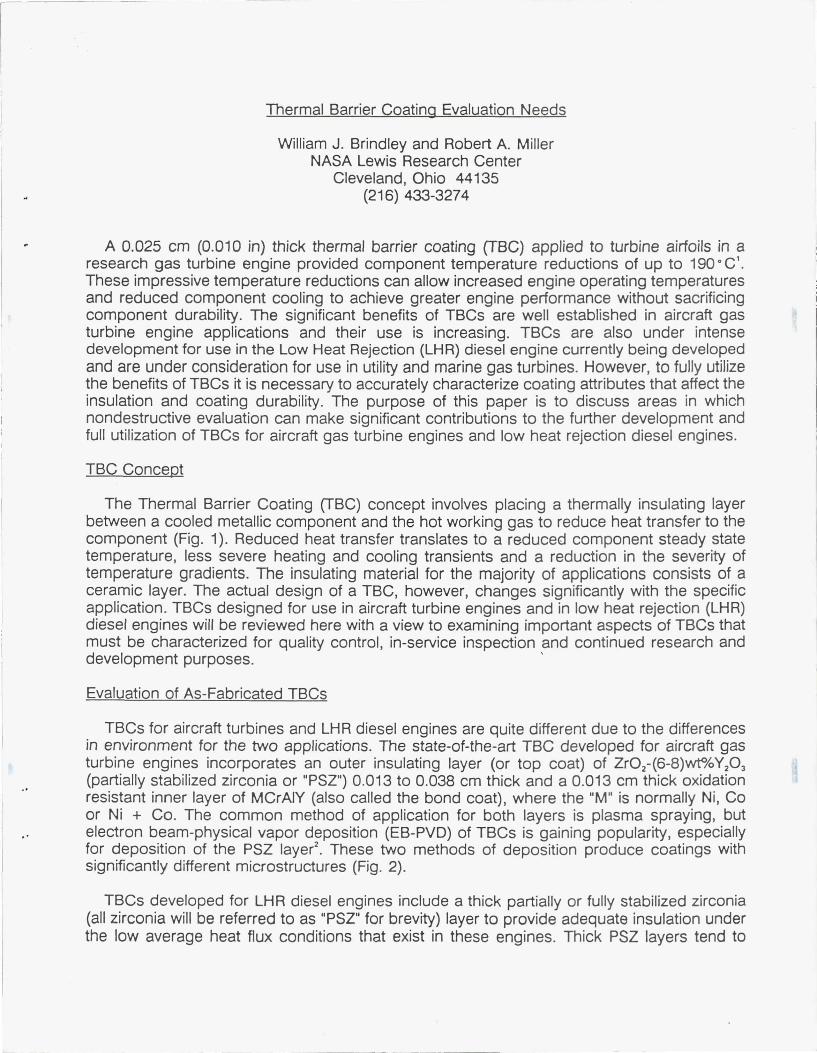
concentrate coefficient of thermal expansion (CTE) mismatch stresses at the topcoat/component interface and therefore have poor durability. Improved durability for thickcoatings is achieved by "grading" the CTE of the coating through the coating thickness.Grading is accomplished by applying a 100% metallic bond coat layer followed by successivelayers of coating with decreasing fractions of bond coat material and increasing fractions ofPSZ ceramic. This type of coating achieves a bulk CTE that changes gradually from thesubstrate to the outer surface. Current generation diesel TBCs achieve reasonable durabilitywith up to four grading layers from the bond coat to the top coat and a total coating thicknessof 0.25 cm or greater (Fig. 3).
The most important physical features of as-fabricated TBCs both for aircraft turbines andLHR diesels are the thickness, density, microstructure, and residual stresses of the coatinglayers S '. These features are important to the insulating value of the TBC and critical to thedurability of the TBC.
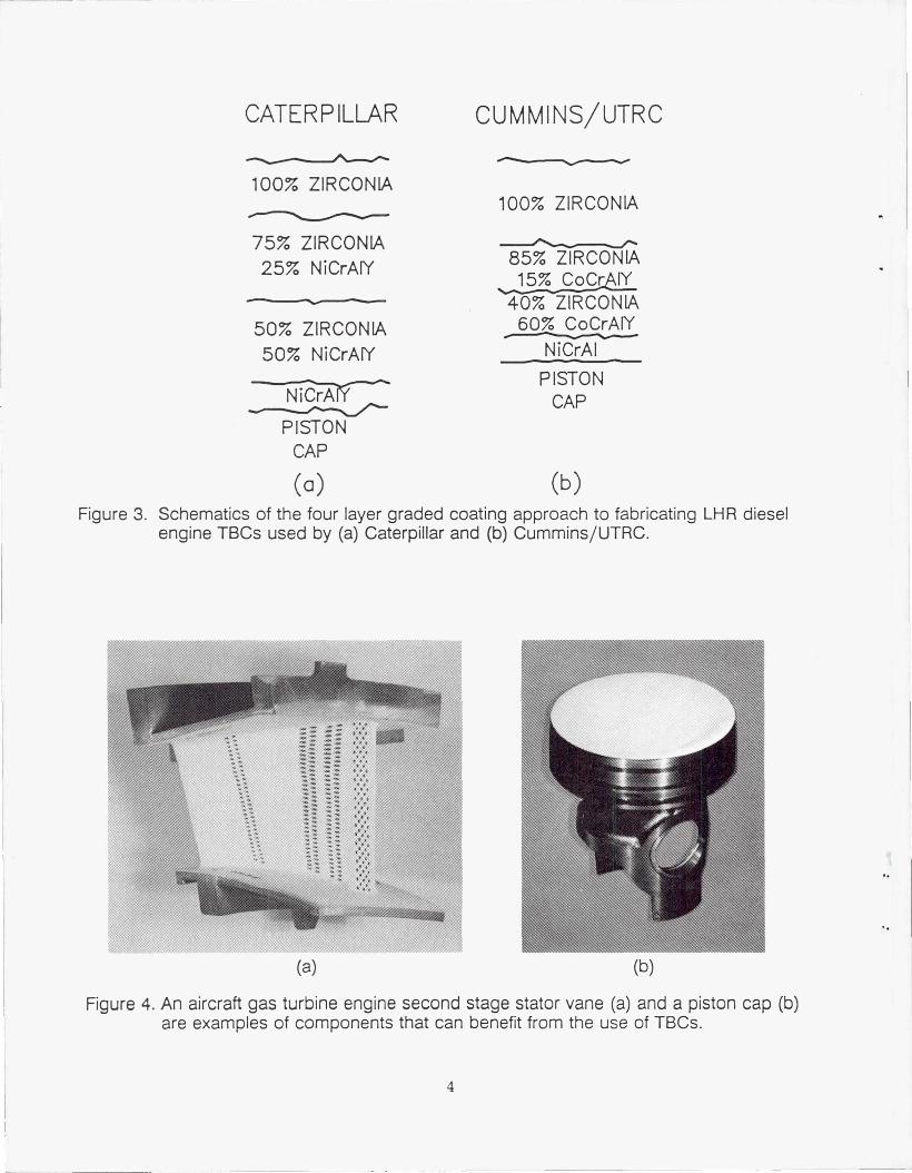
Increased thicknesses of the insulating layer will, of course, increase the insulation of theunderlying component. However, stresses concentrated at the PSZ/bond coat interfaceincrease with increasing thickness of the ceramic layer and will reduce the life of the PSZlayers '. The thicknesses of the graded layers in a diesel TBC are also important to durability'.However, coating thickness is often difficult to measure by normal means (micrometers,calipers, etc) due to complex component shapes (Fig. 4). Complex component shapes canalso present problems in maintaining uniform coating thickness with the line-of-sight depositiontechniques used to fabricate TBCs. Therefore, it is the complex component shapes that mostneed TBC thickness monitoring. Thus, one critical evaluation need for TBCs is a reliablemethod for coating thickness measurement for both process control and quality control.
The durability of the top coat for aircraft TBCs is also a function of the thickness of theoxidation resistant bond coat. Bond coats that are too thin are unable to provide oxidationprotection to the component for extended periods and will tend to provide shorter than desiredPSZ Payer life as well"'. Thus, close control of the bond coat thickness is also important toachieving durable TBCs.
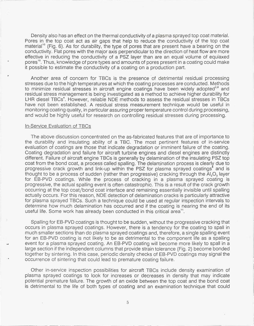
The density of a plasma sprayed top coat (as a fraction of the theoretical density) is criticalto the life of an aircraft engine TBC"' as shown in Figure 5, is suspected to be important tothe life of an EB-PVD aircraft TBC and may also be important to diesel engine TBCs'. Densityvariations may occur as a result of process variations or may result from the combination ofpart shape complexity and the line-of-sight deposition processes that are used. The effect ofdensity on plasma sprayed TBC durability is a result of the strain tolerance gained throughporosity and cracking in the top coat s ' (Fig. 2). The dependence of TBC life on the amount ofporosity is complex in that the ratio of equiaxed pores to flat crack-like pores changes withdensity. Thus, it is not clear if top coat durability should be a strict function of density or afunction of both density and the ratio of the different types of pores. These points have notbeen addressed due to the lack of adequate means of characterizing the pore content of aTBC. Recent advances in metallographic techniques 9 have made possible metallographicexamination of the pore content of coatings and may lead to new information on pore effectson TBC life. Until pore-durability correlations can be made, it is only certain that pore contentof a coating is critical to TBC durability. NDE methods that can characterize both density andthe pore content of a coating are certain to be useful for both quality control and for researchand development.
CATERPILLAR CUMMINS/UTRC
100% ZIRCONIA100% ZIRCONIA
75% ZIRCONIA25% NiCrA(Y 85% ZIRCONIA
15% CoCr IY40% ZIRCONIA
50% ZIRCONIA 60% COCrAIY
50% NiCrAfY NiCrAI
N i CrAPISTON
CAPPISTON
CAP
(a) (b)Figure 3. Schematics of the four layer graded coating approach to fabricating LHR diesel
engine TBCs used by (a) Caterpillar and (b) Cummins/UTRC.
(a) (b)
Figure 4. An aircraft gas turbine engine second stage stator vane (a) and a piston cap (b)are examples of components that can benefit from the use of TBCs.
4
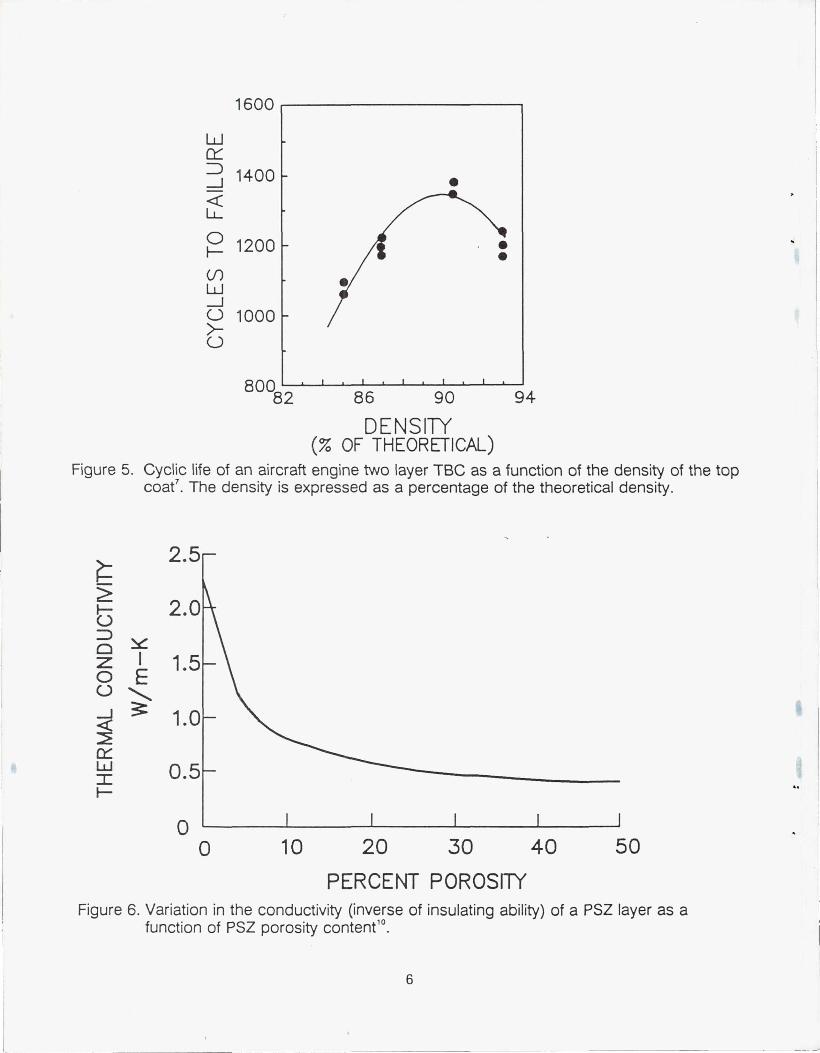
Density also has an effect on the thermal conductivity of a plasma sprayed top coat material.Pores in the top coat act as air gaps that help to reduce the conductivity of the top coatmaterial'° (Fig. 6). As for durability, the type of pores that are present have a bearing on theconductivity. Flat pores with the major axis perpendicular to the direction of heat flow are moreeffective in reducing the conductivity of a PSZ layer than are an equal volume of equiaxedpores". Thus, knowledge of pore types and amounts of pores present in a coating could makeit possible to estimate the conductivity of a coating on a production part.
Another area of concern for TBCs is the presence of detrimental residual processingstresses due to the high temperatures at which the coating processes are conducted. Methodsto minimize residual stresses in aircraft engine coatings have been widely adopted"' andresidual stress management is being investigated as a method to achieve higher durability forLHR diesel TBCs 4 . However, reliable NDE methods to assess the residual stresses in TBCshave not been established. A residual stress measurement technique would be useful inmonitoring coating quality, in particular assuring proper temperature control during processing,and would be highly useful for research on controlling residual stresses during processing.
In-Service Evaluation of TBCs
The above discussion concentrated on the as-fabricated features that are of importance tothe durability and insulating ability of a TBC. The most pertinent features of in-serviceevaluation of coatings are those that indicate degradation or imminent failure of the coating.Coating degradation and failure for aircraft turbine engines and diesel engines are distinctlydifferent. Failure of aircraft engine TBCs is generally by delamination of the insulating PSZ topcoat from the bond coat, a process called spalling. The delamination process is clearly due toprogressive crack growth and link-up within the PSZ for plasma sprayed coatings and isthought to be a process of sudden (rather than progressive) cracking through the AI,O, layerfor EB-PVD coatings. While the process of cracking in a plasma sprayed coating isprogressive, the actual spalling event is often catastrophic. This is a result of the crack growthoccurring at the top coat/bond coat interface and remaining essentially invisible until spallingactually occurs. For this reason, NDE detection of delamination cracks is particularly attractivefor plasma sprayed TBCs. Such a technique could be used at regular inspection intervals todetermine how much delamination has occurred and if the coating is nearing the end of itsuseful life. Some work has already been conducted in this critical area".
Spalling for EB-PVD coatings is thought to be sudden, without the progressive cracking thatoccurs in plasma sprayed coatings. However, there is a tendency for the coating to spall inmuch smaller sections than do plasma sprayed coatings and, therefore, a single spalling eventfor an EB-PVD coating is not likely to be as detrimental to the component life as a spallingevent for a plasma sprayed coating. An EB-PVD coating will become more likely to spall in alarge section if the independent columns that provide strain tolerance (Fig. 2) become bondedtogether by sintering. In this case, periodic density checks of EB-PVD coatings may signal theoccurrence of sintering that could lead to premature coating failure.
Other in-service inspection possibilities for aircraft TBCs include density examination ofplasma sprayed coatings to look for increases or decreases in density that may indicatepotential premature failure. The growth of an oxide between the top coat and the bond coatis detrimental to the life of both types of coating and an examination technique that could
5
2.5^
z2.0U
^ Yz 1.50 EU \Q 1.0
`-L' 0.5
4
1600
WCY
::D 1400
Qt
0 1200
(/")wU 1000
U
80082 86 90 94
DENSITY(% OF THEORETICAL)
Figure 5. Cyclic life of an aircraft engine two layer TBC as a function of the density of the topcoat'. The density is expressed as a percentage of the theoretical density.
0 1 1 1 1 1
0 10 20 30 40 50
PERCENT POROSITYFigure 6. Variation in the conductivity (inverse of insulating ability) of a PSZ layer as a
function of PSZ porosity content'°.
6

determine oxide thicknesses below the PSZ on in-service parts may be helpful in determiningthe remaining life of a part. Finally, both types of coating are subject to erosion due to theirstrain tolerant structures and severe operation environments. Thus, monitoring of in-servicecoating thickness will be essential in future, higher operating temperature aircraft turbines inwhich the insulation provided by a TBC is critical to the short term life of the engine.
In-service inspection requirements for LHR diesel engine TBCs are expected to besomewhat different than for gas turbines. The dominant mode of in-service coating failure isyet to be identified for LHR TBCs but a few degradation mechanisms have been identified.Shallow spalling, which is spalling of chips of PSZ that are a small fraction of the coatingthickness, has been observed for diesel coatings and is attributed to high cycle thermalfatigue'. Shallow spalling could damage the insulating capability of the coating by reducing thecoating thickness. Delamination of TBCs, similar to that in aircraft engines, has also beenobserved and could lead to spalling of significant fractions of the coating thickness. Bothshallow spalling and delamination may be amenable to detection during regular serviceintervals for diesel engines.
CONCLUSIONS
Thermal barrier coatings offer the potential to significantly increase heat engine efficiencyor performance by allowing increased operation temperatures while maintaining componentdurability. However, TBC durability and insulating ability are highly dependent on thickness,density, microstructure and residual stresses. Therefore, establishment of coating evaluationtechniques that can handle the complexities of TBCs is critical to the continuing developmentand use of TBCs for high performance heat engines.
REFERENCES
1. C.H. Liebert and F.S. Stepka, J. Aircraft, 14 [5] 487-493 (1977).2. W.J. Brindley and R.A. Mlller, Adv. Mat. and Proc., 8, 29-33 (1989).3. R.C. Brink, J. Eng. Gas Turbines and Power, 111, 570-577 (1989).4. R.C. Novak, A.P. Matarese and R.P. Huston, Proc. of 26th Automotive Technology
Development Contractor's Coordination Meeting, Dearborn, Michigan, October 24-27, 1988.5. R.A. Miller and C.E. Lowell, Thin Solid Films, 95, 265-273 (1982).6. J.T. DeMasi, K.D. Sheffler and M. Ortiz, NASA Contractor Report CR-182230 (1989).7. S. Stecura, NASA Technical Memorandum 86905 (1985).8. T.E. Strangman, Thin Solid Films, 127, 93-105 (1985).9. W.J. Brindley and T.A. Leonhardt, Mat. Characterization, 24, 93-101 (1990).10. A.P Batakis and J.W.Vogan, NASA Contractor Report 175002 (1982).11. T. E. Strangman, J. Neumann and A. Liu, NASA Contractor Report CR-179648 (1987).
7
National and Report Documentation PageSpace Administration
1. Report No. 2. Government Accession No. 3. Recipient's Catalog No.
NASA TM-103708
4. Title and Subtitle 5. Report Date
Thermal Barrier Coating Evaluation Needs
6. Performing Organization Code
7. Author(s) 8. Performing Organization Report No.
William J. Brindley and Robert A. Miller E-5596
10. Work Unit No.
505-63-1A9. Performing Organization Name and Address
11. Contract or Grant No.National Aeronautics and Space AdministrationLewis Research CenterCleveland, Ohio 44135-3191 13. Type of Report and Period Covered
Technical Memorandum12. Sponsoring Agency Name and Address
National Aeronautics and Space Administration 14. Sponsoring Agency CodeWashington, D.C. 20546-0001
15. Supplementary Notes
Prepared for the Conference on Nondestructive Evaluation of Modern Ceramics cosponsored by the AmericanCeramic Society and the American Society of Nondestructive Testing, Columbus, Ohio, July 9-12, 1990.Responsible person, William J. Brindley (216) 433-3274.
16. Abstract
A 0.025 cm (0.010 in) thick thermal barrier coating (TBC) applied to turbine airfoils in a research gas turbineengine provided component temperature reductions of up to 190 °C i . These impressive temperature reductionscan allow increased engine operating temperatures and reduced component cooling to achieve greater engineperformance without sacrificing component durability. The significant benefits of TBCs are well established inaircraft gas turbine engine applications and their use is increasing. TBCs are also under intense development foruse in the Low Heat Rejection (LHR) diesel engine currently being developed and are under consideration for usein utility and marine gas turbines. However, to fully utilize the benefits of TBCs it is necessary to accuratelycharacterize coating attributes that affect the insulation and coating durability. The purpose of this paper is todiscuss areas in which nondestructive evaluation can make significant contributions to the further developmentand full utilization of TBCs for aircraft gas turbine engines and low heat rejection diesel engines.
17. Key Words (Suggested by Author(s)) 18. Distribution Statement
Thermal barrier coatings; Nondestructive evaluation; Unclassified — UnlimitedAircraft; Diesel; Plasma spray; Physical vapor deposition Subject Category 26, 27
19. Security Classif. (of this report) 20. Security Classif. (of this page) 21. No. of pages 22. Price'
Unclassified Unclassified 8 A02
NASA FORM 1626 OCT 86 *For sale by the National Technical Information Service, Springfield, Virginia 22161