nasa techn ical nasa tm x- 68192 memo ran … · the emission characteristics of natural gas and...
TRANSCRIPT

NASA TECHN ICALMEMO RAN DU M
N 7 3 - 1 9 8 2 4NASA TM X- 68192
000s-i—ioo\O
<to< COPY
DESIGN AND EVALUATION OF COMBUSTORS FOR REDUCING
AIRCRAFT ENGINE POLLUTION
by Robert E. Jones and Jack GrobmanLewis Research CenterCleveland, Ohio 44135
TECHNICAL PAPER proposed for presentation atForty-first Meeting of AGARD/Propulsion and Energetics PanelLpndon, England, April 9-13, 1973
https://ntrs.nasa.gov/search.jsp?R=19730011097 2018-09-09T04:21:53+00:00Z

ABSTRACT
This report summarizes some of the NASA Lewis Research Center1srecent efforts in reducing exhaust emissions from turbine engines.Various techniques employed and the results of testing are brieflydescribed and referenced for detail. The experimental approaches takento reduce oxides of nitrogen emissions include the use of: multizonecombustors incorporating reduced dwell time, fuel-air premixing, airatomization, fuel prevaporization and gaseous fuel. Since emissions ofunburned hydrocarbons and carbon monoxide are caused by poor combustionefficiency at engine idle, the studies of fuel staging in multizonecombustors and air assist fuel nozzles have indicated that large reduc-tions in these emissions can be achieved. Also, the effect of inlet-airhumidity on oxides of nitrogen was studied as well as the very effectivetechnique of direct water injection. The emission characteristics ofnatural gas and propane fuels were measured and compared with those ofASTM-A1 kerosene fuel.

DESIGN AMD EVALUATION OF COMBUSTORS FOR REDUCING AIRCRAFT ENGINE POLLUTION
Robert E. Jones and Jack GrobmanLewis Research Center
National Aeronautics and Space AdministrationCleveland, Ohio 44135
SUMMARY
This report summarizes some of the NASA Lewis Research Center1 s recent efforts in reducing exhaustemissions from turbine engines. Various techniques employed and the results of testing are briefly de-scribed and referenced for detail. The effort arises from the increasing concern for the measurement andcontrol of emissions from gas turbine engines. The greater part of this research is focused on reducingthe oxides of nitrogen formed during takeoff and cruise in both advanced CTOL, high pressure ratio enginesand advanced supersonic aircraft engines. The experimental approaches taken to reduce oxides of nitrogenemissions include the use of: multizone combustors incorporating reduced dwell time, fuel-air premixing,air atomization, fuel prevaporization, water injection and gaseous fuels. In the experiments conducted todate, some of these techniques have been more successful than others in reducing oxides of nitrogen emis-sions. In all cases, considerably more research will be required to develop combustors employing one ormore of these experimental techniques without sacrificing over-all combustor performance. Tests are beingconducted on full-annular combustors at pressures up to 6 atmospheres and on combustor segments at pres-sures up to 30 atmospheres.
Emissions of unburned hydrocarbons and carbon monoxide are caused by poor combustion efficiency atconditions such as engine idle. The use of fuel staging in multizone combustors and air assist fuel nozzleshave indicated that large reductions in hydrocarbon and carbon monoxide emissions can be achieved. Studiesare also being conducted on the use of diffuser bleed and variable combustor geometry to try to optimize thecombustor airflow distribution over the wide range of operating conditions.
The effect of inlet-air humidity on the generation of oxides of nitrogen was studied as well as thevery effective technique of direct water injection. The emission characteristics of natural gas and pro-pane fuels were measured and are compared to those of ASTM-A1 kerosene fuel.
INTRODUCTION
This report describes some of the present efforts of the NASA Lewis Research Center in reducing thepollutant levels of gas turbine engine combustors with the primary emphasis on reducing oxides of nitrogenat takeoff and cruise conditions. Concern over air pollution has drawn the attention of combustionengineers to the quantities of exhaust emissions produced by gas turbine engines. Two general areas ofconcern have been established; urban pollution in the vicinity of airports and pollution in the stratosphere(refs. 1 and 2). The principal urban pollutants are emissions of unburned hydrocarbons and carbon monoxideduring engine idle and taxi, and oxides of nitrogen and smoke during take-off. Oxides of nitrogen arepresently considered to be the most critical emission product during high altitude cruise (ref. 3).
Redesigning the gas turbine combustor to accomplish a significant reduction in oxides of nitrogen willbe a difficult task, since oxides of nitrogen are formed during any combustion process involving air. Theamount formed is controlled by the chemical reaction rate and is a function of the flame temperature,residence time of combustion gases at the highest temperatures, the concentrations of oxygen and nitrogenpresent, and to a lesser extent the combustor pressure. Trends in combustor operating conditions indicatea steady rise in combustor inlet air temperature due to increases in engine pressure ratios and increasinglyhigher flight speeds (ref. 4). These effects increase the flame temperature with subsequent increases inthe production of oxides of nitrogen.
The combustion work reported in this paper is pursuing several varied techniques for reducing the for-mation of gaseous pollutants. To reduce concentrations of oxides of nitrogen, combustors are being testedthat have reduced reaction zone dwell time. Also, studies are also being conducted on ways to reduce thereaction zone temperature. Idle emissions are being reduced by improving combustion efficiency at off-design operating conditions. Combustor smoke is being minimized by careful control of the reaction zoneequivalence ratios and by rapid mixing in the reaction zone.
These techniques for gaseous pollutant control are being evaluated on several full-annular combustorsas well as in high pressure combustor segment tests. Techniques under study include the use of many smallrecirculation zones to reduce reaction zone dwell time, the use of premixing; air atomization and prevapor-ization of fuel; fuel staging and simulated variable combustor geometry; the use of direct water injection;and tests with a variety of fuels including natural gas and propane.
TEST PROCEDURES
Combustor testing is conducted in a variety of connected-duct test facilities at the Lewis ResearchCenter. All inlet-air temperatures are obtained without vitiating the inlet air flow. Several testfacilities have vitiating heaters to raise the inlet temperature still higher. However, they are neverused during tests where the measurement of combustor pollutant levels is required. For fill 1 -annualr com-bustors, tests can be conducted at exact conditions simulating high altitude, high Mach number flight.Each test facility is equipped with on-line gas analysis instruments for pollutant measurements. The ex-haust constituents, COg and CO, are measured using nondispersive infrared (NDIR) instruments, oxides ofnitrogen, NO and N02 are measured using chemiluminescence instruments equipped with a thermal converter toreduce NOg to NO prior to measurement. Unburned hydrocarbons are measured using a flame-ionization detector

maintained at a temperature of 450 K. Unturned hydrocarbons from kerosene fuels are assumed to have thecomposition CHg.
Gas sampling techniques vary from test to test. Most samples are taken from one or more internallymanifolded fixed rakes. Some gas samples are taken with traversing probes on both segment and annular com-bustor tests. The samples are transported to the gas analysis instruments through heated stainless-steeltubes. Sample transit time through the transfer tube is minimized by venting a large amount of the sampleflow at the instruments and by maintaining the pressure in the transfer tube at approximately 2 atmospheres.The sampling procedures and techniques used, follow the guidelines specified in SAE ARP 1256 (ref. 5).Smoke measurements are also made by sampling at the combustor exhaust plane. The smoke number is determinedby collecting the particulates on filter paper and obtaining a reflectance reading of the stain. Thistechnique has been standardized in SAE ARP 1179 (ref. 6).
The representativeness of the gas sample is checked by comparing the computed gas-sample fuel-air ratioto the fuel-air ratio calculated from flow rate measurements. Only data obtained where these fuel airratios agree to within ±15 percent is accepted.
EMISSION REDUCTION RESULTS AND DISCUSSION
Multizone Combustors
Combustor descriptions. - Full annular combustor testing at NASA-Lewis has emphasized two combustorconcepts for decreasing burning zone length. These* are the swirl-can combustor and the double annularcombustor. The swirl-can combustor is shown in Fig. 1 and 2. The combustor is of annular design, 0.514 mlong and 1.067 m in diameter. The combustor consists of 120 individual swirl-can modules which distributecombustion uniformly across the annulus. The modules are arranged in three concentric rows with fuel flowindependently controlled to each row. There are 48 modules in the outer row, 40 in the center and 32 inthe inner row.
The combustor module design is shown in Fig. 3. Each module premixes fuel with air in the carburetor,swirls the mixutre, stabilizes combustion in its wake, and provides interfacial mixing areas between thebypass air through the array and the hot gases in the wake of the module. More detailed information onswirl-can combustors can be found in Refs. 7 to 9.
The other full-annulus combustor being investigated with a shortened burning zone is referred to as adouble-annular, ram induction combustor. A cross-sectional sketch of this combustor is shown in Fig. 4.Constructing the combustion zone as a double-annulus permits the reduction of overall combustor lengthwhile maintaining an adequate ratio of length to annulus height in each combustion zone. This featureallows a considerable reduction in length to be made over a single annulus with the same overall height.
Individual control of the inner and outer annulus fuel systems of the double annular combustion zoneprovides a useful method for adjusting the outlet radial temperature profile.
The ram-induction combustor differs from the more conventional combustors in that the compressordischarge air is allowed to penetrate into the combustion and mixing zones without diffusing to as high astatic pressure. The kinetic energy of the inlet air is thereby used to promote rapid mixing of air andfuel in the primary zone, and of diluent air and burned gases in the mixing zone. The airflow is efficientlyturned into the combustor by two rows of vaned turning scoops that penetrate into the combustor. A moredetailed discussion of the ram-induction concept is provided in Refs. 10 through 14.
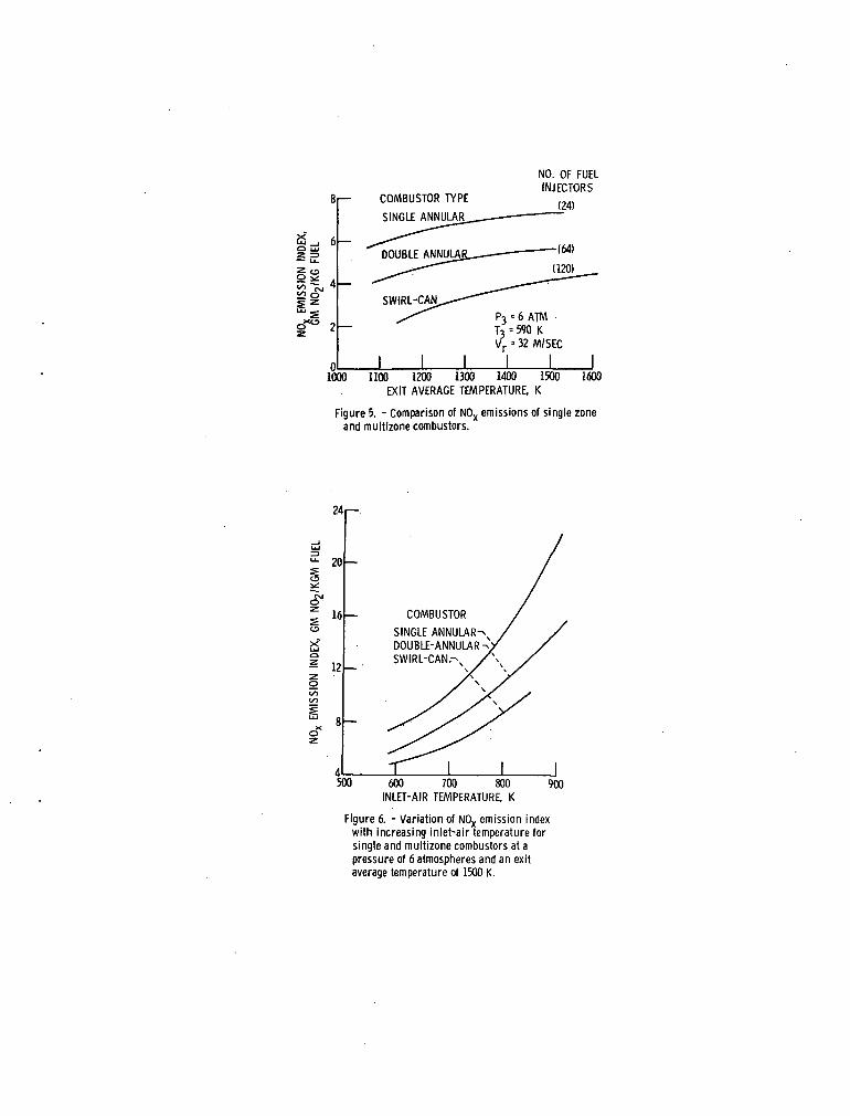
Oxides of nitrogen emissions. - The emissions of oxides of nitrogen (NO + NOg = NOX) for the multizonecombustors are shown in Fig. 5. Also shown on this figure are data from a single-annular combustor,Refs. IS and 16. The NOX emission index, grams of N02 produced per kilogram of fuel burned, is shown as afunction of the combustor exit average temperature. The test conditions; pressure, inlet-air temperatureand reference velocity were the same for all three combustors. The numbers in parentheses are the number offuel injection sources of each combustor. Increasing the number of fuel injection sources and spreadingthe combustion more uniformly throughout the combustor appears to be a very effective way of reducing theemission of NOX. The techniques of premixing fuel and air and rapid quenching of the combustion reaction,both incorporated into the swirl-can approach, are also considered to be a principle factor for producingthe lower NOX emissions of these combustors. Figure 6 compares the NOX emission level for the three com-bustor types with increasing inlet-air temperature and a constant exit temperature of 1500 K. The trendwith increasing inlet-air temperature is an exponential increase in NOX emission index. The use of multi-zone combustors or combustors that spread combustion as much as possible is a very effective way to reduceNOX emissions. At an inlet-air temperature of 755 K the swirl can combustor produces only 60 percent asmuch NOX as the more conventional single-annular combustor. Figure 7 shows the emissions of NOX for theswirl-can combustor for inlet-air temperatures up to 840 K and fuel air ratios up to 0.0695. For theASTM-A1 fuel used in these tests, the stoichiometric fuel-air ratio is 0.0676. This swirl-can combustorwas designed for near stoichiometric operation and as such is larger than would be required for operationat more usual turbine inlet temperatures. The figure shows a strong dependence of NOX emissions on bothinlet-air temperature and on fuel-air ratio. However as the fuel-air ratio is increased the formation ofNOX eventually reaches a constant level and as stoichiometric fuel air ratios are approached the raeas-jredconcentrations of NOX were noticed to decline. Though this effect is only clearly demonstrated at it,-) inlet-air temperature of 590 K, there is no reason to believe that similar effects would not be observed at thehigher inlet-air temperatures. A more complete discussion of all the emission characteristics c,f swirl-cancombustors can be found in Refs. 7 and 8.
The effects of combustor residence time on NOX emissions is shown in Fig. 8 for the two multizone com-bustors. Increasing the combustor reference velocity (decreasing the residence time) causes a correspondingdecrease in the NOX emission level. The effect is virtually linear with residence times as in indicated bythe dashed line with a slope of minus one.
Smoke number. - The smoke emissions of the swirl-can combustor are shown in Fig. 9. These data were

obtained during a test to stoichiometric operating conditions at a pressure Level of 6 atmospheres, (ref. 9).No smoke was detected when the combustor exit temperature was below 1950 K. The smoke increases rapidly asthe overall stoichiometric fuel-air ratio is approached. For comparison, the smoke number of the double-annulus combustor at an exit average temperature of 1500 K and the same operating conditions as on Fig. 9is approximately 14. This illustrates the point that fuel-air premixing as occurs in swirl-cans is a veryeffective way of reducing combustor smoke.
Air Atomization
High pressure combustor tests were made to determine pollutant emissions and performance characteristicsobtained with low fuel pressure drop air-atomizing fuel nozzles designed to utilize the air-stream momentumin atomizing ASTM A-l fuel (ref. 17). Similar tests were made with pressure-atomizing fuel nozzles for com-parison. With the present trend in development toward advanced turbojet engines with high compressor-pressure ratios, the problem of developing low pollutant combustors has become more difficult at the result-ing high levels of inlet-air pressure and temperature.
One of the main advantages of air atomizing fuel nozzles is their flexibility in design in producingfuel sprays which spread out fairly uniformly across the airstream. With improved atomization and mixingobtained from air atomizing fuel nozzles, it would be expected that nitric oxide concentrations could bereduced (ref. 18). Besides being relatively simple in design and fabrication, air atomizing fuel nozzlesare less susceptible to fuel fouling at high inlet-air temperatures as compared with the pressure atomizingtype.
Air atomizing nozzles were tested under ambient flow conditions in a full scale Lucite model of anexperimental combustor to determine spray patterns produced with water injection. Photographs taken atseveral water air ratios and reference velocities showed that a splash cone type of air atomizing nozzlegave a better distribution of liquid and a finer spray of water droplets than that obtained with a radialjet type of air atomizer. As expected from.water spray tests, radial jet nozzles gave high smoke numbersin preliminary combustor tests. Thus, the splash cone air atomizing nozzle, shown in Fig. 10, was selectedfor the high pressure combustor tests.
The fuel nozzle assembly shown in the figure consists of a diffuser snout in which a portion of theair from the compressor is captured and flows through the air swirler and around the splash cone nozzle.The air swirler produces a rotating airflow which assists in evenly distributing the fuel droplets andstabilizing the subsequent flame. Low pressure fuel is injected from the combination fuel supply and splashcone support through four 0.16 cm diameter orifices onto the curved face of the nozzle. Fuel splashes overthe nozzle lip and is atomized by the swirling airstream. At the point where the airstream first contactsthe fuel, the diffuser passage converges to accelerate the flow of the resultant fuel-air mixture which isthen suddenly expanded into the combustor by the diverging portion of the diffuser. The nozzle assemblycan be used either singly or in combination to provide the required distribution for can combustors, can-annular combustors, or annular combustors.
A high pressure combustor segment 0.456 m (18 in.) long with a maximum cross section of 0.153 by0.305 m (6 by 12 in.) was tested with the splash-cone air atomizing and conventional simplex pressure atom-izing fuel nozzles (ref. 17) at inlet-air pressures of 4 to 20 atmospheres, inlet air temperatures as highas 590 K, reference velocities of 12.4 to 26.1 m/sec (41 to 86 ft/sec), and fuel air ratios of 0.008 to0.020. Pollutant emissions obtained with the splash cone air atomizing nozzle configuration are comparedwith results obtained with pressure atomizing fuel nozzles. Most of the results to be described hereinwere obtained at an inlet total temperature of 590 K, a reference velocity of 21.4 m/sec, and a fuel-airratio of 0,015.
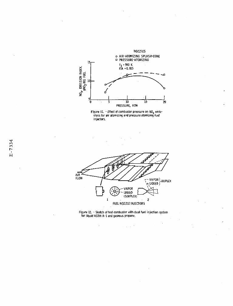
The variation of the nitrogen oxide emission index with pressure is shown in Fig. 11. -Emission indexgenerally increased with increasing inlet air pressure. However, there was a considerable drop in emissionindex with the splash cone nozzle when inlet air pressure was increased from 10 to 20 atmospheres. Thiswas attributed to improved atomization of the fuel when airstream momentum was increased. In this case,momentum was increased by increasing the airstream density. Thus, at an inlet air pressure of 20 atmos-pheres, it was found that the nitrogen oxide emission index was considerably lower with the splash coneair atomizing nozzle than with the pressure atomizing nozzle. These tests were conducted with a fixed airentry hole geometry. It is conceivable that further reductions in oxides of nitrogen might be attained byadjustments in liner airflow distribution.
Increasing inlet air pressure from 4 to 10 atmospheres increased exhaust smoke numbers for all of thefuel nozzles that were tested. However, smoke number decreased slightly with the splash cone nozzle wheninlet air pressure was increased from 10 to 20 atmospheres. As previously mentioned, nitric oxide emissionindex decreased in a similar manner which was attributed to improved fuel atomization when airstreammomentum was increased. Thus, with the air atomizing splash cone nozzle, an improvement in fuel atomizationat high inlet air pressure tended to counteract the general tendency of smoke number to increase with in-creasing inlet air pressure. However, at 20 atmospheres inlet air pressures, the splash cone nozzle had asmoke number of about 35, somewhat higher than one of the pressure atomizing nozzles tested but lower thanthat of another. It should be noted that the inlet air temperature of 590 K was somewhat below the design"takeoff" condition of 20 atmospheres and 755 K (1360° E). Thus, smoke numbers are somewhat higher thanmight be expected at the design takeoff condition since increasing inlet temperatures tend to reduce smokenumber.
Increasing either inlet-air pressure or temperature decreased carbon monoxide and unburned hydrocarbonemission indexes with both the splash cone and pressure atomizing nozzles. The comparison between thesplash cone and the pressure atomizing nozzle indicated that both carbon'monoxide and unburned hydrocarbonswere lower with splash cone nozzles at an inlet air temperature of 589 K (1060° R) over a range of pressureof 4 to 20 atmospheres although the combustion efficiencies for both fuel nozzJ.es were near 100 percent.Initial results for the air atomizing splash cone fuel nozzle are promising but a great deal more research

is required to attain further reductions in oxides of nitrogen and smoke, and to evaluate combustor dura-bility and altitude relight capabilities.
Fuel Prevaporization
A study was conducted to determine the effect of prevaporization on the exhaust emissions from anexperimental combustor (ref. 19). Two methods for reducing oxides of nitrogen are to reduce the reactionzone temperature (flame temperature) and to reduce the reaction zone dwell time. The reaction zone tem-perature may be reduced by operating with a more homogeneous fuel air mixture that is either fuel rich orfuel lean. The fuel air mixture could be made more homogeneous either by increasing mixing intensity,by premixing the fuel and air before they enter the reaction zone, or by prevaporizing the fuel before itenters the reaction zone. A more homogeneous fuel air mixture should also minimize emission productscaused by incomplete combustion. Eliminating the process of fuel droplet evaporation within the reactionzone could enable a reduction in reaction zone dwell time.
Operating a combustor with prevaporized kerosene fuel would require a heat exchanger to convert theliquid fuel to vapor prior to injection into the reaction zone. Due to limitations that might be imposedby the heat exchanger, the combustor may operate with only partially vaporized fuel over a part of theflight conditions. One of the objectives of the tests described herein was to determine emission levelswith varying degrees of vaporization. Vaporized propane was used to simulate vaporized kerosene. Propanewas chosen to eliminate the complexities of operating a liquid fuel boiler and because its burning charac-teristics are similar to kerosene. Two different dual fuel nozzles were used to inject varying proportionsof liquid ASTM A-l fuel and gaeous propane into the test combustor as shown in Fig. 12. The experimentalcombustor that was used is similar to that described in the previous section. At a given fuel-air ratio,the summation of the mass flowrates for liquid ASTM A-l and gaseous propane was held constant as the pro-portion of gaseous propane was varied from 0 to 100 percent. Fuel injector No. 1 consists of a simplexnozzle located in the center of the assembly for injecting liquid kerosene and a series of eight evenlyspaced holes concentric with the simplex orifice for injecting gaseous propane. Fuel injector Ho. 2 isa commercial duplex nozzle in which the center orifice was used for injecting liquid kerosene and theannular orifice was used for injecting gaseous propane. The tests described herein were conducted over arange of inlet pressure and temperature of 4 to 20 atmospheres and 475 to 700 K, respectively, a fuel-airratio of 0.014 and a reference velocity of 21.3 m/sec.
Figure 13 shows the variation in the emission index for oxides of nitrogen with inlet temperature forvarying proportions of gaseous propane. The results obtained using fuel injector No. 1 indicate that asthe inlet temperature is increased from 478 to 700 K, the emission index for oxides of nitrogen increasesfrom 6 to 22 for 0 percent vapor. The effect of vapor fuel on the NOX emission index is negligible up toan inlet temperature of about 590 K. The reduction in NOX that occurred as the proportion of vapor fuelwas increased became more significant as inlet temperature was increased further. At 700 K, a considerableimprovement was obtained, amounting to a 24 percent decrease in NO , as the proportion of vapor was in-creased from 0 to 100 percent. The results obtained with fuel injector No. 2 were similar with the exceptionthat the general level for the HOX emissions was lower.
Figure 14 shows the variation in smoke number with inlet total pressure for varying proportions ofgaseous fuel. As inlet pressure was increased from 4 to 20 atmospheres., the smoke number for fuel injectorNo. 1 increased from 12 to 27 with 0 percent vapor. At a pressure of 20 atmospheres, increasing the pro-portion of vapor from 0 to 100 percent, decreased the smoke number by 60 percent. Fuel injector No. 2produced a marked increase in smoke number as pressure was increased.
Fuel injector Ho. 1 displayed a higher level for the HO emission index but a lower level of smokenumber than injector Ho. 2. The observed differences are attributed to differences in degree of fuel airmixing between the two configurations. It appears that fuel injector Ho. 2 had less mixing causing it tooperate at locally fuel rich conditions thus producing more smoke but lesser amounts of HOX. Ho attemptwas made to alter reaction zone airflow distribution in these tests. The results indicate, however, thatfurther reduction in HOX might be obtained by improvements in fuel air mixing (premixing) or by adjustingthe amount of primary zone airflow.
The combustor operated at combustion efficiencies near 100 percent for all test conditions describedherein. Nevertheless, the emission index for carbon monoxide decreased significantly as the proportionof vapor increased from 0 to 100 percent as shown in Fig. 15. The corresponding emission indices fortotal hydrocarbons were negligible for all test conditions.
Idle Emissions
Emission of unburned hydrocarbons and carbon monoxide are often prevalent during engine idle and taxi.These emissions are of primary concern in the vicinity of airports. The cause of these emissions is poorcombustion efficiency at the combustor operating conditions typical of ground idle. Typically these condi-tions are low combustor pressure, 2 to 4 atmospheres; low inlet-air temperature 355 to 480 K, and low fuel-air ratios of 0.0075 to 0.01. Measured engine combustion efficiencies vary from 88 to 96 percent. Twoapproaches are being tried in an attempt to improve idle combustion efficiency. These are the use of fuelstaging in multizone combustors and use of an air-assisted fuel nozzle.
Fuel staging. - Fuel staging as applied to multizone combustors means that only one of the severalpossible zones receives fuel during idle. When the nvpra.11 fuel-air ratio is maintained at that valuerequired for idle the burning zone has a significantly higher than average fuel-air ratio. With pressureatomizing fuel nozzles this means a higher pressure drop during idle which in turn gives finer atomizationand better combustion efficiency. With swirl-can modules the fuel flow to the active row is high enoughso that a vrell developed spray is formed. At very low fuel flow rates per module the fuel has been observedto dribble rather than be sprayed from the swirl cans. The results of the fuel staging tests are shown intable I and reported in detail in Refs. 8 and 20. The double annulus combustor emissions are compared withcombustion in both annul! and staged to inner annulus. Similar data are shown for the swirl-can combustor.

It is apparent that large reductions in emission levels can be obtained by this simple technique. Thelevels of pollutant reduction demonstrated still may not be sufficient and further improvements may berequired.
Air assist fuel nozzles. - Improving fuel atomization by using an air assist fuel nozzle can signifi-cantly reduce unburned hydrocarbon and carbon monoxide emissions at idle operating conditions by improvingcombustion efficiency. This might be done as shown in Fig. 16. Here a conventional dual orifice fuelnozzle is modified so that during idle, high pressure air is injected through the secondary orifice. Onlysmall amounts of air are needed. For higher power settings the air would be shut off and secondary fuelwould be injected in the conventional manner.
Figure 17 illustrates the reductions in hydrocarbons and carbon monoxide that were obtained by usingair assist fuel injection in a dual orifice nozzle, in a single J-57 engine combustor can at simulatedengine idle conditions. Increases in atomizer air pressure (delta p) represent increases in the air throughone orifice of the fuel nozzle. Fuel is supplied through the other orifice. The addition of air throughthe nozzle improved fuel atomization with the main effect being a dramatic improvement in combustionefficiency. Attendant reductions of approximately 80 percent in hydrocarbons and 30 percent in carbonmonoxide emission index levels were realized. More details on this technique, including a description ofthe nozzle configuration, are given in Ref. 21.
Control of Combustor Airflow Distribution
Another technique which may have substantial potential for reducing emissions is the control of thecombustor airflow distribution as a way of controlling the primary zone equivalence ratio. Two approachesare being taken: the use of short diffusers incorporating bleed for airflow profile control; and the useof variable combustor geometry.
Diffuser tests. - Short diffusers incorporating bleed on both walls are being tested in a full annulustest facility described in Eef. 22. This test facility has the capability to test many different diffusergeometries. Tests have been conducted on an asymmetric wall diffusers (ref. 23), dump diffusers and a widevariety of short length diffusers incorporating bleed on both diffuser walls. We find that large changesin the diffuser exit flow profile can be caused by the application of small quantities of bleed flow.Additionally, bleed can cause the diffuser to flow more efficiently and diffuser total pressure losses canbe significantly reduced.
An application of diffuser bleed is illustrated in Fig. 18. As shown in Fig. 18(a) the combustorinlet velocity profile without bleed has the majority of the airflow bypassing the primary zone. Thiscondition should be optimum for low pollutant emissions at idle and enhanced altitude relight capability.At takeoff and cruise conditions, Fig. 18(b), the combustor inlet velocity profile is straightened byapplying outer wall bleed for optimum operation.
Variable geometry. - Variable combustor geometry could be a very effective way of controlling thecombustor primary zone equivalence ratio. At conditions such as engine idle variable geometry could beused to optimize the primary zone equivalence ratio to minimize the emissions of hydrocarbons and carbonmonoxide. Similarly at altitude relight conditions the primary zone fuel air ratio could be optimizedfor reignition. At take-off or cruise the combustor geometry would again be changed and now optimizedto minimize smoke and oxidies of nitrogen. At present the only variable geometry configurations beingstudied are for improved altitude relight and improved idle emission control. This work is being doneon a modified version of the double-annulus combustor.
Water Injection Tests
Direct injection of water into the primary zone of a combustor is another very effective way to mini-mize the emissions of oxides of nitrogen. However, practical aircraft considerations limit the use of waterinjection only for takeoff. Water injection lowers the flame temperature and serves as a diluent in theair stream. Both effects reduce the maximum combustion temperature and thereby reduce the emissions ofNOX. Figure 19 compares data for three different combustors all using slightly different techniques fordirect water injection. The ratio of NOX emission indices with and without water injection is shown as afunction of the water-air ratio. Water injection in the single annular combustor was by spraying waterinto the combustor snout upstream of each fuel nozzle. Water injection in the segment combustor was fromthe secondary ports of the nozzles used for comparison of propane fuel injection (nozzle No. 1, fig. 12).Water injected in this manner mixes much more intimately with the fuel and is significantly more effectivein reducing NOX emissions. These effects however do influence the levels of other pollutants as combustionefficiency may be lowered by water injection. Some increase in CO levels during water injection have beenobserved but are not considered to be significant in view of the low values without water injection.
Inlet air humidity. - Variations in inlet-air humidity have been shown to reduce the level of oxidesof nitrogen emissions. Tests were conducted using the single annular combustor described previously.Water was sprayed into the inlet-air far enough upstream of the combustor so that it would be completelyvaporized before reaching the combustor. The results of these tests are shown in Fig. 20. Data wereobtained over a wide range of inlet-air temperatures and humidities. The trends with increasing humidityare the same; an exponential decrease in the NOX emission index with increasing humidity.
Alternate Fuels
The single annular combustor of Hef. 15 has been tested with natural gas fuel. Reference 25 givesdetails of the work done to determine an optimum method of injecting natural gas fuel. Natural gas doesnot display stable combustion over as wide a range of operating conditions as conventional kerosene fuelsused in aircraft turbine engines in spite of its higher heating value. The narrow combustible limits andhigh chemical stability account for the poor performance of natural gas fuel at off design engine operatingconditions, Refs. 26 and 27.

Hatural gas does have an advantage over keorsene fuels in its well documented tendency to producelower emissions of NOX (ref. 28). Figure 21 compares the emissions of N0x for ASTM-A1 fuel and naturalgas fuel over a range of inlet-air temperatures. Exit temperature was constant at approximately 1500 K,combustion efficiency was approximately 100 percent and test pressure was 6 atmospheres. In general, theuse of natural gas resulted in approximately a fifty percent reduction in HOX emissions. In an attemptto further reduce the emissions of NOX, direct water injection was tried. As expected, the combustorperformance was severely degraded. At an inlet-air temperature of 590 K, the combustor blew out at a water-air ratio of 0.025. Direct water injection was marked by noisy, unstable combustion and reduced combusionefficiency. Gas analysis data show that about 90 percent of the combustion inefficiency is due directlyto unburned fuel. Where combustion could be maintained, the use of direct water injection did decreasethe emissions of NOX.
CONCLUDING REMARKS
Research on most of the combustor concepts mentioned will be continuing in an effort to better under-stand ways of minimizing the pollutants from combustors. The goals that have been established for futuregas turbine engines will require that there be new technology in combustor design. Several trends andapproaches are well understood but with the exception of exhaust sincke have yet to be demonstrated onflight engines. In addition to the aircraft engine emissions research being conducted "in-house" byNASA/Lewis, a contracted effort designated as the "Experimental Clean Combustor Program" has recently beeninitiated. The goal of the "Experimental Clean Combustor Program" is to make a substantial reduction inall pollutant levels of advanced CTOL engines. The primary emphasis of these contracts will be to demon-strate a 75 percent reduction in NOX emissions. However there will also be attempts to significantlyreduce the emissions at idle. Demonstration of the best combustor concepts will evenutally include groundstatic tests in a large high pressure ratio engine.
REFERENCES
1. Plott, M.; Baker, H. C.; Bastress, E. K.j Change, K. M.; and Siegel, R. 0.: The Potential Impact ofAircraft Emissions Upon Air Quality. Rep. 1167-1, Northern Research and Engineering Corp., 1971.
2. Sawyer, R. F.: Atmospheric Pollution by Aircraft Engines and Fuels. AGARD-AR-40, 1972.
3. Anon.: Proceedings of the Survey Conference, Climatic Impact Assessment Program. Rep. DOT-TSC-OST-72-13, Department of Transportation, 1972.
4. Grobman, J.; Jones, R. E.; Marek, C. J.; and Niedzwiecki, W.: Combustion. Aircraft Propulsion.NASA SP-259, 1971, pp. 97-134.
5. Anon.: Procedure for the Continuous Sampling and Measurement of Gaseous Emissions from AircraftTurbine Engines. Rep. ARP 1256, SAE, Oct. 1971.
6. Anon.: Aircraft Gas Turbine Exhaust Smoke Measurement. Rep. ARP 1179, SAE, May 1970.
7. Niedzweicki, R. W.; and Jones, R. E.: Pollution Measurements of a Swirl-Can Combustor. NASATM X-68160, 1972.
8. Niedzwiecki, R. W.; Trout, A. M.; Mularz, E.: Performance of a Swirl-Can Combustor at Idle Conditions.NASA TM X-2578, 1972.
9. Niedzwiecki, R. W.; Juhasz, A. J.; and Anderson, D. N.: Performance of a Swirl-Can Primary Combustorto Outlet Temperatures of 3600° F (2256 K). NASA TM X-52902, 1970.
10, Perkins, P. J.; Schultz, D. F.; and Wear, J. D.: Full-Scale Tests of a Short Length, Double-AnnularRam-Induction Turbojet Combustor for Supersonic Flight. NASA TN D-6254, 1971.
11, Clements, T. R.: 90-Degree Sector Development of a Short Length Combustor for a Supersonic CruiseTurbofan Engine. Rep. PWA-FH-3790, Pratt & Whitney Aircraft (NASA CH072734), 1970.
12, Schultz, D. F.; and Perkins, P. J.: Effects of Radial and Circumferential Inlet Velocity Profile Dis-tortions on Performance of a Short-Length Double-Annular Ram-Induction Ccmbustor. NASA TN D-6706, 1972.
13, Schultz, D. F.; and Mularz, E. J.: Factors Affecting Altitude Relight Performance of a Double-AnnularRam-Induction Combustor. NASA TM X-2630, 1972.
14, Clements, T. R.: Development of a Short Length Combustor for a Supersonic Cruise Turbofan EngineUsing a 90 Degree Sector of a Full Annulus. Rep. PVJA-FE-4854, Pratt & Whitney Aircraft (NASACR-120908), Apr. 1972.
15, Wear, J. D.; Perkins, P. J.- and Schultz, D. F.: Tests of a Full-Scale Annular-Induction Combustorfor a Mach 3 Cruise Turbojet Engine. NASA TN D-6041, 1970.
16, Rusnak, J. P.; and Shadowen, J. H.: Development of an Advanced Annular Combustor. Rep. PWA-FR-2832,Pratt & Whitney Aircraft (NASA CR-72453), May 30, 1969.
17, Ingebo, R. D.; and Norgren, C. T.: High Pressure Combustor Exhaust Emissions with Improved Air-Atomizing and Conventional Pressure Atomizing Fuel Nozzles. Proposed NASA Technical Note.
18, Pompei, F.; and Heywood, J. B.: The Role of Mixing in Burner Generated Carbon Monoxide and NitricOxide. Rep. 722j Dept. Mech. Eng., Massachusetts Inst. Tech., Feb. 1972.

19. Horgren, C. T.j and Ingebo, R. D.: Investigation of the Effect of Prevaporized Fuel on the ExhaustEmissions from an Experimental Gas Turbine Combustor. Proposed NASA Technical Memorandum.
20. Clements, T. R.: Effect of Fuel Zoning and Fuel Nozzle Design on Pollution Emissions at Ground IdleConditions for a Double-Annular Ram-Induction Combustor. Prayy & Whitney Aircraft (HASACR-120194), 1972.
21. Brlehl, D.; and Papathakos, L.: Use of an Air-Assist Fuel Nozzle to Reduce Exhaust Emissions from aGas-Turbine Combustor at Simulated Idle Conditions. NASA TN D-6404, 1971.
22. Juhasz, A. J.; and Holdeman, J. D.: Preliminary Investigation of Diffuser Wall Bleed to ControlCombustor Inlet Airflow Distribution. NASA TN D-6435, 1971.
23. Juhasz, A. J.: Control of Exit Velocity Profile of an Asymmetric Annular Diffuser Using Wall Suction.NASA TM X-2710, 1972.
24. Bahr, D. W.: Control and Reduction of Aircraft Turbine Engine Exhaust Emissions. Symposium onEmissions from Continuous Combustion Systems. General Motors Research Lab., Warren, Mich., Sept. 1971.
25. Wear, J. D.,• and Schultz, D. F.: Effects of Fuel Nozzle Design on Performance of an ExperimentalAnnular Combustor Using Natural Gas Fuel. NASA TN D-7072, 1972.
26. Hibbard, R. R.: Evaluation of Liquified Hydrocarbon Gases as Turbojet Fuels. NACA RM E56I21, 1956.
27. Wear, J. D.; and Jones, R. E.: Comparison of the Combustion Characteristics of ASTM Al, Propane andNatural Gas Fuels in an Advanced Annular Combustor. NASA TN D-7135, 1972.
28. Hilt, M. B.; and Johnson, R. H.: Nitric Oxide Abatement in Heavy Duty Gas Turbine Combustors by Meansof Aerodynamics and Water Injection. Paper #72-GT-53, ASME, Mar. 1972.
TABLE I. - EFFECT OF FUEL STAGING
Idle Operation
P3 = 4 atmT3 = 480 Kf = 0.008
Type ofcombustor
SwirlCan
DoubleAnnular
Annulus
AllInner
BothInner
Effi-ciency
<50-100
92-100
H/C
>20015
9815
CO
-8040
13278

71.12(28.0)
(31.9)
PLANE OF FUELINJECTION -'
54.36(21.4)
Figure 1. - Full annular model of high-temperature combustor.(Dimensions in centimeters (in.).)
C-70-869
Figure 2. - Annular swirl-can-modular combustor.

CARBURETOR
PLATE FLAMESTABILIZER-'
SWIRLER FLAMESTABILIZER
CS-56698
Figure 3. - Combustor module details.
WIDTH
I
LENGTH
LTYPICAL SCOOP(END VIEW)
-TURNING VANES
12.0(30.5)
SPARK PLUG
rOUTER SHROUD
AND SWIRLERS-'
Figured -Cross-section of double-annular ram induction combustor.
Dimensions are in inches (cm).
§-•O UJ
« 4
COMBUSTOR TYPE
SINGLE ANNUUR
NO. OF FUELINJECTORS
(24)
P3 •6 ATMT3 = 590 KVr • 32 M/SEC
1000 1100 1200 1300 1400 1500EXIT AVERAGE TEMPERATURE, K
1600
Figure 5. - Comparison of NOX emissions of single zoneand multizone combustors.
24r—
20
16
* 12
COMBUSTOR
SINGLE ANNULAR-DOUBLE-ANNULARSWIRL-CAN.-
500 600 700 800 900INLET-AIR TEMPERATURE, K
Figure 6. - Variation of NOX emission indexwith increasing inlet-air temperature forsingle and multizone combustors at apressure of 6 atmospheres and an exitaverage temperature of 1500 K.

20 r-
.020 .030 .040 .050FUEL-AIR RATIO
.060 .070
COCO Figure 7. - Effects of combustor inlet temperature and
fuel-air ratio on oxides of nitrogen formation in aswirl-can combustor. Combustor inlet pressure,5 to 6 atmospheres: airflow, 38.5 to 50 kg/sec.
10
S 41/1
o DOUBLE-ANNULARo SWIRL-CAN
10 20 40 50REFERENCE VELOCITY, M/SEC
Figure 8. - Effect of reference velocity onNOX emissions of multizone combus-tors. Inlet-air temperature, 590 K;inlet pressure, 6 atmospheres.

24
20
16
12
P~6 ATMT3 - 590 K
NODETECTABLE xx
SMOKE |I
1900 2000 210Q 2200 2300COMBUSTOR EXIT TEMPERATURE, K
Figure 9. - Variation of smoke number with exittemperature for the swirl-can combustor.
SWIRLER
^AIR-ATOMIZING SPLASH-CONE
Figure 10, - Sketch of high pressure combustor using air atomizingsplash cone fuel injectors.
15
SSto —
10
NOZZLES
o AIR-ATOMIZING SPLASH-CONEo PRESSURE-ATOMIZING
T3F/F/A
590 K=0.015
10PRESSURE, ATM
15 20
Figure II. - Effect of combustor pressure on NOX emfs-sions for air atomizing and pressure atomizing fuelinjectors.
ror-i
W
AIRFLOW
r-VAPOR*"- LIQUID
(SIMPLEX)1 2
FUEL NOZZLE INJECTORS
Figure 12. - Sketch of test combustor with dual fuel injection systemfor liquid'ASTM A-l and gaseous propane.

24
20
„12
FUEL NOZZLEINJECTOR
12
ol_450 500 550 600 650
INLET-AIR TOTAL TEMPERATURE,
700 750
Figure 13. - Variation in NOX emission index with inlettotal temperature for various percentages of gaseouspropane.
80
60
40
20
FUEL NOZZLEINJECTOR
12
4 8 12 16INLET-AIR TOTAL PRESSURE, ATM
20
Figure 14. - Variation in smoke number with inlet total temp-erature for various percentages of gaseous propane.

CO
t-
W
60
50
40
30
I 2 0
FUEL NOZZLEINJECTOR
10caof.
450 550 650 750
INLET-AIR TOTAL TEMPERATURE, K
Figure 15. - Variation in carbon monoxide emission in-dex with inlet total temperature for various percent-ages of gaseous propane.
SUPERCHARGER
SECONDARY
FUEL[FOR TAKEOFF]
& CRUISE J
| COMPRESSOR
BLEED AIR
(FOR IDLE) *PRIMARY
FUEL
Figure 16. - Sketch of air-assist fuel injection system.
oo
.100
ATOMIZER AIR, AP, PSI
60§2
200
o <</» 5t/j r!
20 §2
CS-60209
Figure 17. - Variations in combustion efficiency and emis-sion indices for carbon monoxide and total hydrocarbonswith the atomizer pressure drop of an air-assist fuelnozzle at simulated idle conditions.

FUEL NOZZLEHGNITOR
BLEED PORTS >.
AIR FLOW
INLET VELOCITY PROFILE-'
(A) IDLE OR ALTITUDE RELIGHT OPERATION.
INLET VELOCITY PROFILED
(B) CRUISE OR TAKEOFF OPERATION.
Figure 18. - Application of diffuser bleed in conventional annular combustor.
1.0oS .8ce
S .4GO
—LU
2LU
8 2rv • *-
fe00LU
i -1§ .08
-ASTM-AI
OF REF 23
PROPANE
SEGMENT TESTS— SINGLE ANNULUS COMBUSTOR
0 1 2 . 3% WATER INJECTED, GM WATER/100 GM AIR
Figure 19. - Effect of water injection on emissions of oxidesof nitrogen.

roCOr-i
W
.01 .02 .03 .04INLET HUMIDITY, KG H20/KG DRY AIR
.05
figure 20. - Effect of inlet air humidity on NOX emisions.Combustor pressure, 6 atmospheres,- exit temperature,1500 K.
20
2510
o ASTM-AIa NATURAL GAS
400 500 600 700 800 900INLET AIR TEMPERATURE, K
Figure 21. - Comparison of NOX emissions of ASTM-1 andnatural gas fuels. Combgstor pressure, 6 atmospheres;exit temperature, 1500 K.
NASA-Lewis-Com'l