nasa technical nasa tm x-71452 memorandum
TRANSCRIPT
NASA TECHNICAL NASA TM X-71452MEMORANDUM
C\j
(NASA-TN-X-7t45 2 ) THE ATOMIC NATURE OF N73-33390
X POLYMER-NETAL INTERACTIONS IN ADHESION,, FRICTION AND NEAR (NASA) 18 p BC $3.00
- CSCL 07D UnclasG3/15 19401
THE ATOMIC NATURE OF POLYMER-METAL INTERACTIONS
IN ADHES ION, FR ICT ION AND WEAR
by Donald H. Buckley and William A. Brainard
Lewis Research Center
Cleveland, Ohio 44135
TECHNICAL PAPER proposed for presentation at
Symposium on Advances in Polymer Friction and Wear
sponsored by the American Chemical Society
Los Angeles, California, March 31-April 4, 1974
THE ATOMIC NATURE OF POLYMER-METAL INTERACTIONS INADHESION, FRICTION AND WEAR
byDonald H. Buckley and William A. Brainard
National Aeronautics and Space AdministrationLewis Research CenterCleveland, Ohio 44135
INTRODUCTION
In lubrication systems polymers are frequently used in sliding or rollingcontact with metal surfaces. It is of interest therefore to study the funda-mental surface interactions between these polymers and metals and the mannerin which those interactions influence adhesion, friction and wear.
Of solids the polymers used, PTFE (polytetra-fliuorothylene) and polyimide aretwo structures with inherently good self-lubricating and transfer character-istics. Unlike polymers such as nylon they do not depend upon the presenceof adsorbates such as water vapor or other environmental constituents fortheir low adhesion, friction and wear propertiesl-3 .
Another type of polymer-metal interaction that has been observed is associ-ated with the formation of polymeric surface films from the interaction ofmonomers or (lower molecular weight species) with metal surfaces in slidingcontact. Frictional energy provides the activation energy for polymerization.This phenomenon was first observed in electrical contacts 4 -5 . And more re-cently it has been observed in friction and wear studies6 - 7.
The objectives of this paper are twofold, first, to examine the adhesion,friction and wear behavior of the solid polymers PTFE and polyimide withvarious metals and second, to gain insight into the role of the friction pro-cess in the generation of polymer surface films. Analytical surface toolsincluding field ion microscopy, Auger emission spectroscopy and scanningelectron microscopy were used to examine the atomic nature of polymer - metalsurface interactions.
MATERIALS
The solid polymer bodies of PTFE and polyimide used in these studies were re-search grade materials. The polymer forming gaseous monomer vinyl chloride,was 99.95 percent in purity as was the ethyl chloride.
The metals used were iron, tungsten, gold, and aluminum. The tungsten, gold,and aluminum were all 99.999 percent and the iron was 99.99 + percent inpurity.
EXPERIMENTAL RESULTS
Solid Polymers
Field ion microscopy. - The field ion microscope (FIM) is a powerful tool forstudying the adhesion process. A combination of high magnification and reso-lution of 2-3 A permits the adhesion process to be studied in atomic detail.The principals and operation of the FIM are described by MUller 8, who alsodemonstrated that adhesion could be studied with the FIM9 .
A schematic-of the FIM used as an adhesion apparatus is shown in Fig. 1i. Aspecially constructed contact device can be moved into place under the fieldion tip by the compression of bellows. With suitable voltage applied to the
1
electromagnets, the beam can be made to move upward and contact the field ion
tip. The load applied during contact is determined by the change in output
voltage from a solar cell. PTFE or polyimide is mounted on the surface of a
thin (0.002 cm) gold foil. When contact is made, the foil deflects downward
cutting off some of the light illuminating a solar cell surface thus changing
the output voltage (see Ref. 10 for details). When the beam is moved down-
ward away from the tip, the adhesion between the tip and the PTFE or polyimide
pull the foil upward past the original zero load point until separation oc-
curs. Calibration of the loads applied to the foil to cause given voltage
changes was done with an electronic balance with a sensitivity of <1 g.
A series of PTFE-tungsten contacts were made at loads between 20-30 g and
the force of adhesion measured. Figure 2 is a micrograph taken prior to con-
tact of a tungsten tip. Figure 3 is a photomicrograph taken following con-
tact with PTFE for a few seconds. Many extra image points are apparent on
the post contact micrograph particularly on the (1l0) plane. Adsorbed or ad-
hered atoms can be observed because the geometry of the extra atoms on the
surface of the flat creates points of localized field enhancement resulting
in increased probability of ionization. Thus, clusters visible on the (ll0)
plane are fragments of FTFE which remain adhered to the tungsten surface
after separation has occurred. The other bright image spots also represent
PTFE on the metal surface but their cluster-like nature cannot be resolved.
The fragments of FPTFE have the appearance of the end of a PTFE chain which is
normal to the (1l0) plane. The fact that the fragments are stable at the
very high electric field required for helium ion imaging implies that the
bonding between the PTFE and tungsten is very strong, otherwise field de-
sorption of the adhered PTFE would occur.
To obtain a measure of the bonding between the PTFE and tungsten, the forces
of adhesion were measured for a number of contacts over varying periods of
contact time. The results are summarized in Fig. 4. For short contact
times, the forces of adhesion were immeasurably small. After 2 minutes, how-
ever, the force of adhesion increased markedly. At contact .times of 4-6 min-
utes, adhesion coefficients approaching those for clean metals in contact
were obtained.
It was observed that negligible adhesion force was obtained when a second
contact was made with a previously contacted tip indicating the adhesive
polymer to metal bond is stronger than the cohesive polymer bond. Polymer
radicals can be expected to occur as a result of the breaking of chains, by
the chemical interaction between polymer and metal. Thus, for PTFE contact-
ing a clean tungsten surface, the possibility of unsatisfied valence states
of carbon atoms in FTFE bonding to tungsten exists.
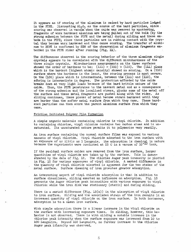
A heavily loaded tungsten - PTFE (approximately three times more load -1 mg)
contact gave the rather surprising result that extensive deformation of the
tungsten occurred. The deformation extended far into the bulk of the mate-
rial as shown in Fig. 5, which was taken after extensive field evaporation
(an effective increase in tip radius of approximately 50 percent). Gener-
ally, during heavy loaded contacts the tip will bend so that the image is
often displaced on the screen; however, there is no displacement of (1l0) in
the micrograph of Fig. 5. The tip, when pressed into the PFE, may be pre-
vented from bending and thus absorbing the stress further up the shank by
the very large area of contact (relative to metal-metal contacts).
Mechanical contacts with a polyimide polymer contacting tungsten tips were
made in vacuum of 10 - 9 torr with both light and heavy loads. At light loads
the results obtained were analogous to those obtained with PTFE. Random
distribution of bright spots were visible indicative of polymer fragments
adhering to.the tungsten. Spots (polymer fragments) were particularly
heavily clustered on the (110) surface as was observed with PTFE.
2
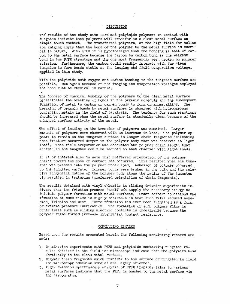
To determine if load would significantly influence the polyimide-tungstencontacts, an experiment was conducted with polyimide contacting tungstenusing a load approximately three times greater than that used for light loadcontacts. Figure 6 is the image of the same tungsten tip after a heavilyloaded polyimide contact. The results show a series of elongated spots allradially projected outward from a dark nonimaging area on the right side ofthe micrograph. As was also observed with PTFE, it appears that the polyimidepolymer fragments have been oriented by the radial stresses projecting out-ward from the center of contact, where the center of contact is the dark re-gion to the right in the micrograph.
Auger emission snectroscopy. - Auger emission spectroscopy (AES), provides atechnique for determining the chemical composition of a surface for elementsheavier than helium with a high degree of sensitivity (i.e., 1/100th of amonolayer). 'AES was used in conjunction with a vacuum friction apparatus toprovide an instantaneous chemical analysis of a metal surface during bothstatic and dynamic contact with PTFE. The experimental apparatus is shown inFig. 7 and further details on the technique and equipment are available inthe literaturel2.
Static contact. - Transfer of PTFE to atomically clean metals by static con-tact was observed for all metals used. These included iron, tungsten, alumi-num, and gold. Figure 8 shows three Auger spectrograms for a gold surfacebefore and after adhesive contact. The presence of carbon and fluorine in
Fig. 8(b) indicate the transfer of PTFE to the gold surface.
The possibility that the transfer of PTFE to metal might be adversely af-fected by the presence of an oxide film on the metal was investigated by twomethods. In the first method, high-purity oxygen was admitted to the chamberafter the disk surface had been sputter cleaned with the oxygen being chemi-sorbed on the surface to monolayer coverage. Static contact was then ini-tiated, and.again transfer of PTFE was observed. Thus, the presence of amonolayer of chemisorbed oxygen does not prevent the transfer observed.
The second method, involved the use of a pre-oxidized aluminum disk. It isknown that the natural oxide layer on aluminum is many layers thick. Re-moving the adsorbed carbon dioxide and carbon monoxide by a short sputtering(20 min) exposed the "clean" aluminum oxide layer. Static contact was againinitiated, and again PTFE was found on the surface. Thus, PTFE transfers tothe oxide of aluminum as well as to the clean metal, which implies that thechemical activity of the substrate was not an important factor in the trans-fer observed in these static contact experiments.
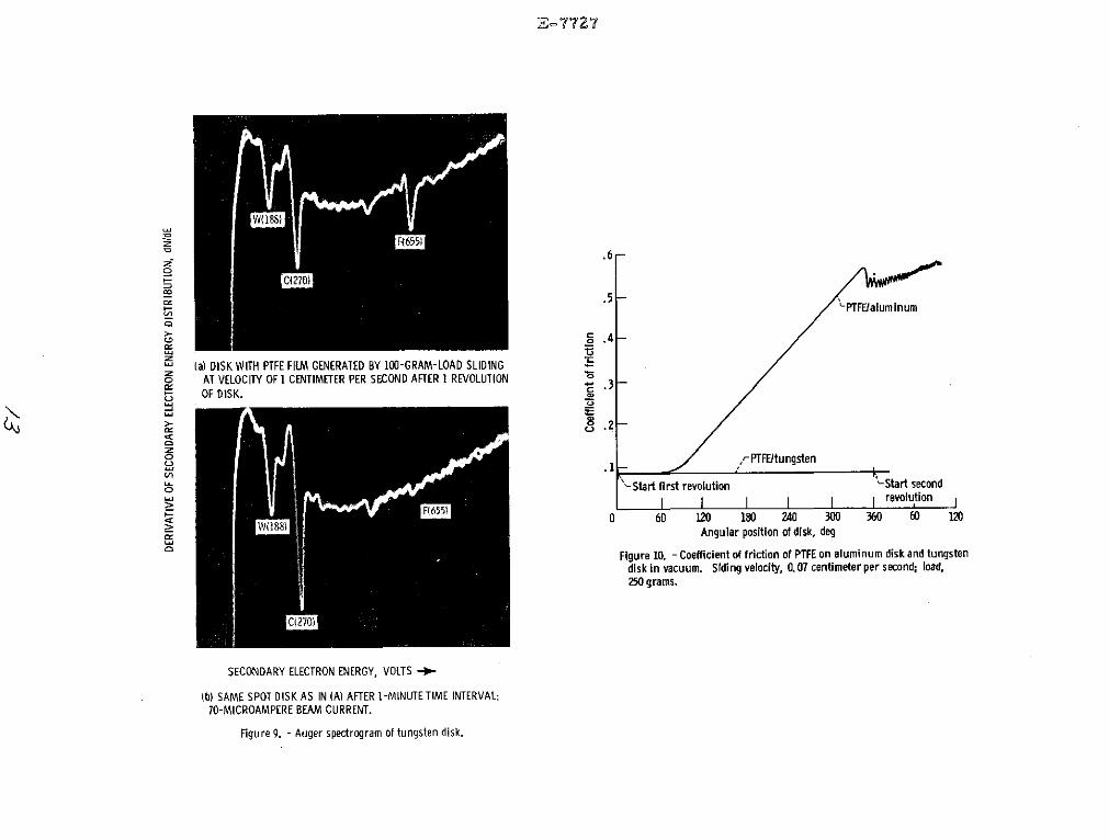
Sliding contact. - Sliding contact was initiated on an atomically clean tung-sten disk. The velocity was 1.0 centimeter per second, and the load was100 grams. A transfer film of PTFE was generated on the disk during thefirst revolution. The Auger spectrogram is shown in Fig. 9(a). The carbonand fluorine peaks were much larger than those in the static contact experi-ments and indicated the presence of larger amounts of PTFE on the surface.
The film appeared uniform across the track, as indicated by the constance ofthe peaks when the deflection plates in the electron gun moved the beamacross the track. The film also appeared uniform and continuous along thecircumference of the track, as indicated by the constancy of the peaksthroughout the first revolution of the disk.
Notice that the tungsten peak is still visible in the Auger spectrum. Thisindicates that the film was only a few monolayers thick, since AES is sensi-tive only to the first few layers on the surface.
Information on the structure of the film and its interaction with the sub-strate may be obtained from the time dependence of the Auger peaks when the
3

disk is held stationary and the electron beam impinges on one spot of the
surface. In Fig. 9, the two spectra were taken 60 seconds apart. It can be
seen that the fluorine peak has decreased while the carbon and tungsten peaks
have grown. The incident 2000-eV electrons usdd to excite the Auger transi-
tions have severed the carbon-fluorine bonds in the PTFE, and the fluorine
has desorbed from the surface. With the departure of the fluorine, Auger
electrons from the carbon and tungsten can leave the surface, enter the
analyzer, and cause growth of these peaks. Exposure of the surface to the
electron beam for about 1 minute resulted in domplete disappearance of the
fluorine peak (Fig. 2(b)).
Pepperl3 calculated the cross section value for electron induced fluorine
desportion from the time dependence of the fluorine Auger peak as 5X10- 1 8
cm2 ), thusly implying no interactions exist between the fluorine in the PTFE
and the metal substrate. This indicates that bonding to the metal must be
via the carbon atom.
Figure 10 shows the curve of friction coefficient versus number of passes of
the disk for PTFE sliding on atomically clean tungsten and aluminum. The
value of 0.08 obtained for PTFE on tungsten is consistent with values usually
reported for PTFE sliding on metals in air. The friction for PTFE on alumi-
num, however, rose drastically from 0.08 at the start to over 0.5 in less
than one complete revoluti6n. Severe "machining" of the aluminum disk oc-
curred and metal cut from the wear track could be seen at the rider-disk con-
tact zone, as well as chips of aluminum covering the surface. The severe
scoring of the aluminum occurred both in the presence or absence of a oxide
film.
Scanning electron microscopy. - To further study the behavior of the PTFE-
metal system, a series of experiments were conducted in air with face cen-
tered cubic aluminum single crystals. The crystals were of (l11), (110), and
(100) orientations. Friction tracks were generated by sliding PTFE over the
electropolished single crystals and then examining the resulting wear tracks
and rider wear scars in the scanning electron microscope (SEM).
Sliding wear tracks were generated on each ok the three single crystal sur-
faces under loads of 100 and 200 grams. Single passes as well as multi-
passes over the same track were made at a sliding velocity of 0.07 cm/sec.
In all cases, large disordered areas of PTFE were observed adhering to the
aluminum surfaces at the initial contact area. Extending out of these areas
were linear fibers of PTFE parallel to the surface. These were oriented inthe direction of sliding.
The friction coefficients for the three crystals were in the range of ap-
proximately 0.06 to 0.20 during sliding. The friction on the (111) surfacewas generally the lowest (0.06 : fk).
On the (111) plane, no damage to the aluminum surface was observed with a
single pass of the rider at either 100 or 200 grams loads. Further, repeatedpasses over the same track did not damage the metal surface. At 100 gram
loads no scoring was observed on the (100) plane but scoring was observed on
the (110) plane. On the (100) and (110) planes, fine score marks were ob-
served on the aluminum surface after.a single pass at 200 grams. Higher mag-nification micrographs taken for the 200 gram load showed areas where piecesof aluminum had been plucked out of the bulk.
For PTFE sliding on the (100) plane, although no scoring was observed for asingle pass at 100 grams load, fine score marks were observed after threepasses over the same wear track. On the (110) plane, repeated passes re-sulted in extensive scoring for a 200 gram load. In general, score marks onboth planes were found to terminate with a fragment of PTFE which had beenpulled out of the bulk.
4
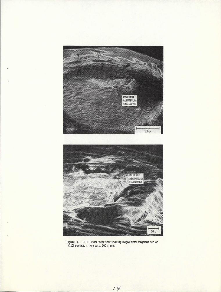
It appears as if scoring of the aluminum is caused by hard particles lodgedin the PTFE. Discounting A12 03 as the source of the hard particles, sincescoring was observed in vacuum when the oxide was removed by sputtering,fragments of work hardened aluminum are being bulled out of the bulk (by thestrong adhesion between the PTFE and the metal) during sliding and these em-bede in the PTFE; since these particles are in rubbing contact with the crys-tal they become work hardened and thus cause scoring. The transfer of alumi-num to PTFE is confirmed by SEM of the observation of aluminum fragments em-
bedded in the PTFE rider after running (Fig. 11).
The differences observed in the scoring behavior of the three aluminum singlecrystals appears to be correlated with the different microhardness of thethree single crystals. Microhardness measurements on the three surfacesshowed the order of hardness to be: (111) > (100) > (110). The (111) planewhich is the hardest (highest atomic density) showed no scoring. On a (11O0)
surface where the hardness is the least, the scoring process is most severe.
On the (100) plane which is intermediate, between the (1ll1) and (110), thescoring is intermediate in degree. The protection 'afforded by the oxide
breaks down at very light loads because of the hard brittle nature of the
oxide. Thus, the PTFE penetrates to the nascent metal and as a consequenceof the strong adhesion and the localized stress, plucks some of the metal off
the surface and these metal fragments are pushed along with the rider. Assliding continues, these pieces of metal become strain hardened until theyare harder than the softer metal surface from which they came. These hard-ened particles can then score the .parent aluminum surface from which theycame.
Friction Initiated Polymer Film Formation
A simple organic molecule containing chlorine is vinyl chloride. In additionto containing chlorine, vinyl chloride contains two carbon atoms and is un-saturated. Its unsaturated nature permits it to polymerize very readily.
An iron surface containing the normal surface films was exposed to variousamounts of vinyl chloride. Vinyl chloride adsorbed to the iron surface withan exposure of as little as 1 Langmuir. The adsorption is chemical in naturebecause the experiments were conducted at 23 C in a vacuum of 101- torr.
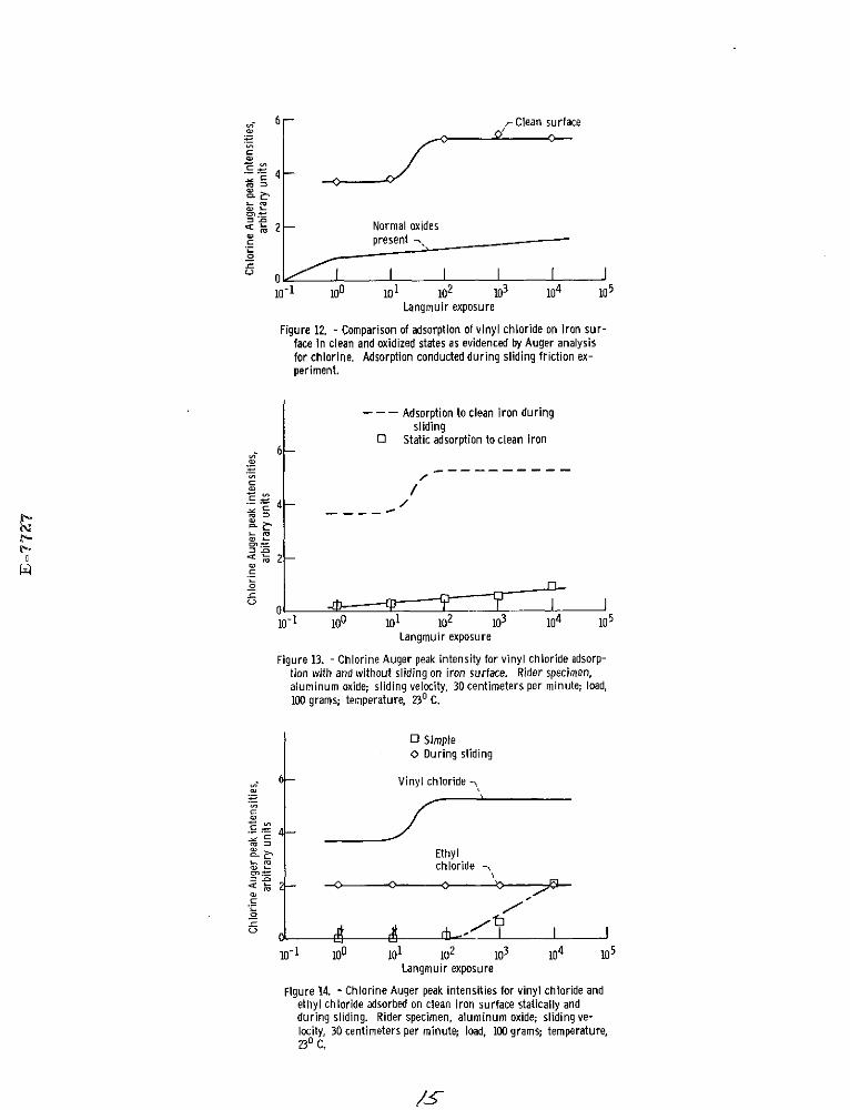
If the residual surface oxides are removed from the iron surface, larger
quantities of vinyl chloride are taken up by the surface. This is demon-strated by the data of Fig. 12. The chlorine Auger peak intensity is plottedin Fig. 12 for various exposures of vinyl chloride. A marked difference inthe quantity of vinyl chloride adsorbed is apparent for the two states of themetal surface. Surface cleaning of iron promotes greater adsorption.
An interesting aspect of vinyl chloride adsorption is that in addition tosurface cleanliness, sliding exerted an influence on adsorption. Fig. 13presents the Auger chlorine peak intensities with various exposure to vinylchloride while the iron disk was stationary (static) and during sliding.
There is a marked difference (Fig. 13(a)) in the adsorption of vinyl chlorideto iron surface. Sliding and the associated strain of the iron results in anincreased quantity of vinyl chloride on the iron surface. In both instances,adsorption is to a clean iron surface.
With simple adsorption there is a linear increase in the vinyl chloride onthe surface with increasing exposure times. In sliding, however, this be-havior is not observed. There is with sliding a notable increase in thechlorine peak intensity when the surface exposure was increased from 10 to100 Langmuirs. Beyond 100 Langmuirs, no further increase in the chlorineAuger peak intensity was observed.
5

Vinyl chloride is a polymer forming material. Ethyl chloride, its saturated
equivalent, is not. Both molecules contain twb carbon atoms and one chlorine.
An iron disk surface was exposed to ethyl chloride. The chlorine Auger peak
intensity observed is plotted in Fig. 14.
An examination of Fig. 14 indicates that the iron surface becomes essentially
saturated with ethyl chloride at an exposure of 1 Langmuir. No change in
Auger chlorine peak intensity was observed beyond 1 Langmuir. Ethyl chloride
is chemically more .reactive than vinyl chloride. This may account for no
further increase in Auger chlorine peak intensity with exposures to ethylchloride greater than 1 Langmuir. This may also be a result of the limiting
depth detectability of Auger analysis (four to five atomic layers).
The observation to be made from Fig. 14 is that even though vinyl chloride is
less reactive than its saturated equivalent, ethyl chloride, a greater con-
centration of vinyl chloride develops on the surface of iron with sliding.
This can be related to the ability of vinyl chloride to polymerize. Chemi-
sorption is a monolayer process. That is, once a ionolayer has formed,chemisorption to the iron surface is complete. Subsequent increases in
hydrocarbon surface concentration must result from chemical reaction or poly-
merization in these experiments. The lesser chemical reactive nature of
vinyl chloride would seem to indicate that polymerization is accounting for
the differences in surface concentration for vinyl and ethyl chlorides seen
in Fig. 14.
Static adsorption studies were conducted on clean iron surfaces with vinyl
and with ethyl chlorides. After 10 000 Langmuirs exposure, there was a
greater concentration of ethyl than vinyl chloride on the iron surface.
Thus, the normally greater reactivity of ethyl chloride was confirmed. This
is also additional evidence for the polymerization of vinyl chloride. The
sliding friction process appears to be initiating this polymerization.
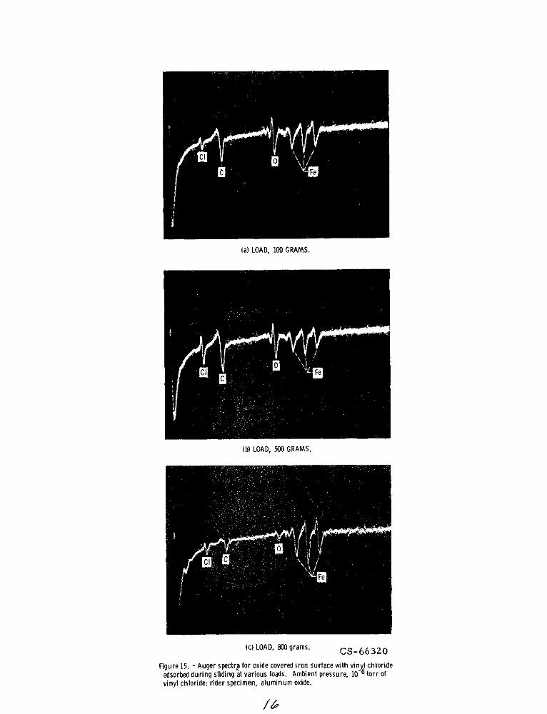
Hydrocarbons are generally in contact in practical lubrication systems with
oxide covered surfaces. Some sliding friction experiments were conducted
with iron containing its naturally occurring oxides in an environment of
vinyl chloride at various loads. The objective of the experiments was to
determine the influence of a mechanical parameter such as loading on surface
reactions. The aluminun oxide rider was loaded against the unsputtered iron
disk at loads from 100 to 800 grams. Sliding was done in vinyl chloride at
a pressure of lxl0- 6 torr. Results obtained in these experiments are pre-
sented in Figs. 15 and 16.
Figure 15 is a presentation of three Auger traces. In Fig. 15(a) the load
employed was 100 grams. The chlorine Auger peak is present but small. When
the load is increased to 500 grams (Fig. 15(b)), the chlorine Auger peak in-
creases indicating a higher concentration of vinyl chloride on the surface.
A further increase in load results in a reduction in the chlorine Auger peak
intensity as seen in Fig. 15(c).
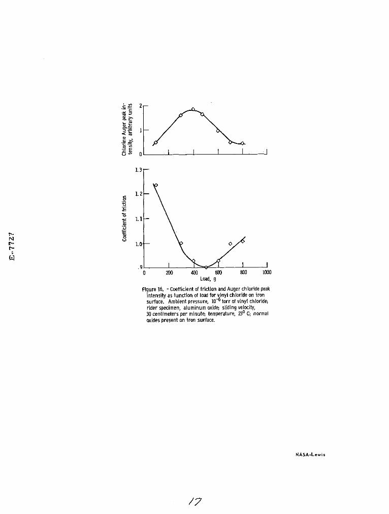
The chlorine Auger peak intensities and friction coefficients for a number
of loads are presented in the data of Fig. 16. In Fig. 16 an increase in
load results in an increase in chlorine Auger peak intensity to 500 grams.
Beyond 500 grams a decrease in chlorine peak intensity occurs. Friction co-
efficient is strongly dependent upon the concentration of vinyl chloride
present on the surface. Where the chlorine peak intensity is maximum in
Fig. 16 friction is at a minimum. To a point, increasing the load has a
beneficial effect in the adsorption of vinyl chloride and in the decrease of
friction. There is, however, an optimum beyond which load is detrimental to
both.
6
DISCUSSION
The results of the study with PTFE and polyimide polymers in contact withtungsten indicate that polymers will transfer' to a clean metal surface onsimple touch contact. The transferred polymers, at the high field for heliumion imaging imply that the bond of the polymer to the metal surface is chemi-cal in nature. With PTFE it is hypothesized that the bonding is that of car-bon to the metal surface because the carbon to carbon bond is the weakestbond in the PTFE structure and the one most frequently seen broken on polymerscission. Furthermore, the carbon could readily interact with the cleantungsten to form bonds stable at the imaging ahd field evaporation voltagesapplied in this study.
With the polyimide both oxygen and carbon bonding to the tungsten surface arepossible. But again because of the imaging and evaporation voltages employedthe bond must be chemical in nature.
The concept of chemical bonding of the polymers to the clean metal surfacenecessitates the breaking of bonds in the organic molecule and the subsequentformation of metal to carbon or oxygen bonds to form organometallics. Thebreaking of organic bonds by metal surfaces is observed with hydrocarbonscontacting metals in the field of catalysis. The tendency for such reactionsshould be increased when the metal surface is atomically clean because of theenhanced surface activity of the metal.
The effect of loading in the transfer of polymers was examined. Largeramounts of polymers were observed with an increase in load. The polymer ap-pears to remain on the tungsten surface in longer chain fragments indicatingthat fracture occurred deeper in the polymer body than was observed at lightload . When field evaporation was conducted the polymer chain length thatadhered to the tungsten could be reduced to that observed with light loads.
It is of interest also to note that preferred orientation of the polymerchains toward the zone of contact has occurred. This resulted when the tung-sten was pressed into the polymer under load. Adhesion of polymer occurredto the tungsten surface. Polymer bonds were broken in the bulk and the rela-tive tangential motion of the polymer body along the radius of the tungstentip resulted in texturing (preferred orientation of chain fragments).
The results obtained with vinyl chloride in sliding friction experiments in-dicate that the friction process itself ca: supply the necessary energy toinitiate polymer formation with metal surfaces. Under certain conditions theformation of such films is highly desirable in that such films reduced adhe-sion, friction and wear. There f6rmation has even been suggested as a formof extreme pressure lubrication. The formation of such polymer films inother areas such as sliding electric contacts is undesirable because thepolymer films formed increase interfacial contact resistance.
CONCLUDING REMARKS
Based upon the results presented herein the following concluding remarks aremade:
1. In adhesion experiments with PTFE and polyimide contacting tungsten re-sults obtained in the field ion microscope indicate that the polymers bondchemically to the clean metal surface.
2. Polymer chain fragments which transfer to the surface of tungsten in fieldion microscopy adhesion studies are highly oriented.
3. Auger emission spectroscopy analysis of PTFE transfer films to variousmetal surfaces indicate that the PTFE is bonded to the metal surface viathe carbon atom.
7
4. With PTFE in sliding contact with different orientations of aluminum,metal orientation is found to influence surfaces in sliding. The lowest
friction and least amount of surface damage is detected on the highest
atomic density (11) plane.
5. The friction process itself can initiate polymer film formation from sim-
ple organic molecules. *The tendency is more pronounded for polymer for-
mation with clean metals than for oxide covered metal surfaces.
REFERENCES
1. Steijn, R. P., ASM, Met. Eng., Quest, 7-9 (1967).
2. Makinson, K. R., and Tabor, D., Proc. Ray. (London), Sec. A, A281. 49
(1964).3. Buckley, D. H., and Johnson, R. L., SPE Trans., 4, 306 (1964).
4. Hermance, H. W., and Egan, T. T., Bill Sys. Tech. Jour. 37, 739 (1958).
5. Skinner, S. M., Savage, R. L., and Ruizler, Jr., J. E., Jour. App.
' Physi. 24, 438 (1953).
6. Fein, R. S., and Kreuz, K. L., ASLE Trans., 8, 29 (1953).
7. Fein, R. S., and Kreuz, K. L., ACS Div. of Pet. Chem. 13 327 (1968).
8. Miller, E. W., Adv. Electronics Electron Phys. 13, 83 (1960).
9. MUller, E. W., and Nishikawa, 0., Adhesion on Cold Welding of Mate-
rials in Space Environments, ASTM Spec. Tech. Publ., no. 431, 67
(1968).10. Brainard, W. A., and Buckley, D. H., NASA TN D-6492 (1971).
11. Brainard, W. A., and Buckley, D. H., NASA TN D-6524 (1971).
12. Buckley, D. H., and Pepper, S. V.,. NASA TN D-6497 (1971)..
13. Pepper, S. V., and Buckley, D. H., NASA TN D-6983 (1972).
14. Holm, R., Electrical Contacts Handbook, Springe - Verlag, Berlin,3rd ed. (1958).
8

HIGH VOLTAGE LEAD 7
-BELLOWS
/
rELECTROMAGNET
NITROGEN SHROUD /
COLD FINGER-VIEWING WINDOW-
BELLOWS- BEARING-\ I I
FEEDTHROUGHS / , OPTICALLY FLAT ,FOR INTENSIFIERI / PHOSPHOR COATED BLEED IN
// VIEWING WINDOW VALVE
LCONTACTING CD-10784-17SFLAT SPECIMEN
S Figure 1. - Schematic of field ion microscope.
Figure 2. - FIM image of tungsten tip prior to contact (18.0 kV, heliumimage gas, liquid nitrogen cooling).image gas, liquid nitrogen cooling).

Figure 3. - FIM image of tungsten tip following contact with PTFE(16.5 kV, helium image gas, liquid helium cooling).
Solid symbols denote unmeasurably small forceSingle-tailed symbol denotes contact with previously
4_ contacted tipDouble-tailed symbol denotes contact in air
3
<1
0 1 2 3 4 5 6Time in contact, min
Figure 4. - Adhesion coefficients for PTFE-tungsten contacts.
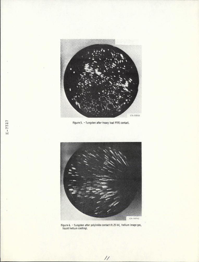
Figure 5. - Tungsten after heavy load PTFE contact.C.-
Figure 6. - Tungsten after polyimide contact (9.25 kV, helium image gas,liquid helium cooling).
1/

rBELLOWS ANDI GIMBAL ASSEMBLY o
FRICTION FORCE- -AUGERCYLINDRICA Au(150)I /-AUGER CYLI NDRI CAL o Au(270)/ /' MIRROR SPECTROMETER
RIDER7 I , 1-,DIS-
,/-DI SK // rCOLD CATHODE GAGE-NUDE />-
LOAD I I 1ONGAGE ION PUMP
zzo (a) CLEAN SURFACE.
c,
N, C CD-11442-15
S--' / VARIABLE LEAK LDISK- I VALVE 1)
/ MAGNETIC I LTO SORPTION 0DRIVE PUMPS
LPROTECTIVE L-SHUTTER LEADS FOR
SPUTTER CLEANING
Figure 7. - Friction apparatus with Auger spectrometer.
SECONDARY ELECTRON ENERGY, VOLTS--
(b) AFTER 500-GRAM-LOAD STATIC CONTACT FOR 1 MINUTE WITH PTFE.
Figure8. - Auger spectrogram of gold surface.
E-7727
C(270)
-. 5F TFElaluminum
g .4-
(a) DISK WITH PTFE FILM GENERATED BY 100-GRAM-LOAD SLIDINGAT VELOCITY OF 1 CENTIMETER PER SECOND AFTER 1 REVOLUTION
U, OF DISK.
.1-
U,
"-Start first revolution '-Start second
I I I I I revolution
0 60 120 180 240 300 360 60 120Angular position of disk, deg
Figure 10. - Coefficient of friction of PTFE on aluminum disk and tungstendisk in vacuum. Siding velocity, 0.07 centimeter per second; load,250 grams.
SECONDARY ELECTRON ENERGY, VOLTS -
(b) SAME SPOT DISK AS IN (A) AFTER 1-MINUTE TIME INTERVAL;70-MICROAMPERE BEAM CURRENT.
Figure 9. - Auger spectrogram of tungsten disk.
FRAGMENT
100 l
10 pFigure 11. - PTFE - rider-wear scar showing lodged metal fragment run on
(110) surface, single pass, 200 grams.
- 6 - ,-Clean surface
S 4-
< 2 - Normal oxidesSpresent -,
10-1 100 101 102 103 104 105Langmuir exposure
Figure 12. - Comparison of adsorption of vinyl chloride on iron sur-face in clean and oxidized states as evidenced by Auger analysisfor chlorine. Adsorption conducted during sliding friction ex-periment.
- - - Adsorption to clean iron duringsliding
O Static adsorption to clean iron
- -, -/
4 -
0
10-1 100 101 102 103 104 105
Langmuir exposure
Figure 13. - Chlorine Auger peak intensity for vinyl chloride adsorp-tion with and without sliding on iron surface. Rider specimen,aluminum oxide; sliding velocity, 30 centimeters per minute; load,100 grams; temperature, 230 C.
0 Simple0 During sliding
6 - Vinyl chloride -
4-
Ethylchloride
< 1 rh- I I I10-1 100 101 102 103 104 105
Langmuir exposure
Figure 14. - Chlorine Auger peak intensities for vinyl chloride andethyl chloride adsorbed on clean iron surface statically andduring sliding. Rider specimen, aluminum oxide; sliding ve-locity, 30 centimeters per minute; load, 100 grams; temperature,230 C.
/3-
(a) LOAD, 100 GRAMS.
(b) LOAD, 500 GRAMS.
(c) LOAD, 800 grams. CS-66320
Figure 15. - Auger spectra for oxide covered iron surface with vinyl chlorideadsorbed during sliding at various loads. Ambient pressure, 10- 6 torr ofvinyl chloride; rider specimen, aluminum oxide.
1.3
1.2 -
0.E 1. 1
r- 1.0
.9 I I I0 200 400 600 800 1000
Load, g
Figure 16. - Coefficient of friction and Auger chloride peakintensity as function of load for vinyl chloride on ironsurface. Ambient pressure, 10- 6 torr of vinyl chloride;rider specimen, aluminum oxide; sliding velocity,30 centimeters per minute; temperature, 230 C; normaloxides present on iron surface.
NASA-Lewis
/