nasa technical note technical note k two-dimensional analysis of heat and mass transfer ... the...
TRANSCRIPT

NASA TECHNICAL NOTE k
TWO-DIMENSIONAL ANALYSIS OF HEAT AND MASS TRANSFER IN POROUS MEDIA USING THE STRONGLY IMPLICIT PROCEDURE
by Donald M . Czlrry
Lyndon B. Johnson Space Center Hoaston, Texus 77058
NATIONAL AERONAUTICS A N D SPACE ADMINISTRATION 0 WASHINGTON, D. C, 0 MARCH 1974
https://ntrs.nasa.gov/search.jsp?R=19740010443 2018-05-30T16:50:43+00:00Z

1. Report No. NASA TN D- 7608
I 4. Title and Subtitle
TWO-DIMENSIONAL ANALYSIS OF HEAT AND MASS TRANSFER IN POROUS MEDIA USING THE STRONGLY IMPLICIT PROCEDURE
7. Author(sJ
Donald M. Curry, JSC
9. Performing Organization Name and Address
Lyndon B. Johnson Space Center Houston, Texas 77058
2. Government Accession No. 3. Recipient's Catalog No.
5. Report Date March 1974
12. Sponsoring Agency Name and Address National Aeronautics and Space Administration Washington, D. C. 20546
6. Performing Organization Code
13. Type of Report and Period Covered
Technical Note 14. Sponsoring Agency Code
8. Performing Organization Report No. JSC S-382
10. Work Unit No. 986-15-31-04-72
11. Contract or Grant No.
17. Key Words (Suggested by Author(s) J
' Porous Materials * Ablation * Convection * Momentum Equations Conduction
* Energy Equations 18. Distribution Statement
Subject Category 33
I 15. Supplementary Notes
19. Security Classif. (of this report)
None -
16. Abstract
Numerical results of the heat and mass transfer in a porous matrix are presented. The coupled, nonlinear partial differential equations describing this physical phenomenon are solved in finite difference form for two dimensions, using a new iterative technique (the strongly implicit procedure). The influence of the external environmFnt conditions (heating and pressure) is shown to produce two-dimensional flow in the porous matrix. Typical fluid and solid temperature distributions in the porous matrix and internal pressure distributions are presented.
20. Security Classif. (of this page) 21. NO. of Pages 22. Price
None 36 $3.00
* For sale by the National Technical Information Service, Springfield, Virginia 22151

CONTENTS
Section Page
SUMMARY. . . . . . . . . . . . . . . . . . . . . . . . . . . . . . . . . . . . . . 1
INTRODUCTION . . . . . . . . . . . . . . . . . . . . . . . . . . . . . . . . . . . 1
SYMBOLS . . . . . . . . . . . . . . . . . . . . . . . . . . . . . . . . . . . . . . 3
THEORETICAL RELATIONS . . . . . . . . . . . . . . . . . . . . . . . . . . . . 5
BOUNDARY AND INITIAL CONDITIONS . . . . . . . . . . . . . . . . . . . . . . 7
IMPLICIT DIFFERENCE EQUATION FORMULATION . . . . . . . . . . . . . . . 9
STRONGLY IMPLICIT PROCEDURE . . . . . . . . . . . . . . . . . . . . . . . . 11
SOLUTIONTECHNIQUE . . . . . . . . . . . . . . . . . . . . . . . . . . . . . . 14
NUMERICAL RESULTS . . . . . . . . . . . . . . . . . . . . . . . . . . . . . . . 15
Isothermal Solutions . . . . . . . . . . . . . . . . . . . . . . . . . . . . . . . 16
Nonisothermal Solutions . . . . . . . . . . . . . . . . . . . . . . . . . . . . . . 17
CONCLUDING REMARKS . . . . . . . . . . . . . . . . . . . . . . . . . . . . . . 22
APPENDIX A- DERIVATION O F THEORETICAL RELATIONS . . . . . . . . . 23
APPENDIX B - FINITE DIFFERENCE RELATIONS USING THE STRONGLY IMPLICIT TECHNIQUE . . . . . . . . . . . . . . . . . . . . 27
REFERENCES.. . . . . . . . . . . . . . . . . . . . . . . . . . . . . . . . . . . 30
iii
TABLE
Table Page
I THERMOPHYSICAL PROPERTIES OF POROUS CHAR MATRIX
(a) Constant property values . . . . . . . . . . . . . . . . . . . . . . . 18 (b) Thermal conductivity ks as a function of temperature . . . . . . . 18 (c) Specific heat C as a function of temperature . . . . . . . . . . 18
PS
FIGURES
Figure Page
1 Two-dimensional porous matrix . . . . . . . . . . . . . . . . . . . . . 7
2 Two-dimensional region with rectangular grid . . . . . . . . . . . . . 9
3 Grid model for definition of upper and lower matrices . . . . . . . . . 12
4 Illustration of boundary condition restrictions . . . . . . . . . . . . . . 13
5 Numerical iteration procedure . . . . . . . . . . . . . . . . . . . . . . 15
6 External pressure gradient, heat flux, and mass injection flux ratios used to simulate typical Apollo conditions; where P = P(O,O) ,
%tag Ref
isothermal flow with the external pressure gradient (metallic matrix); where PStag = 2.03 X 10 N/m 110.3 kg/m -hr . . . . . . . . . . . . . . . . . . . . . . . . . . . .
Stag = q(O,O), and m = xh(Lx,O) . . . . . . . . . . . . . . . . . 15
7 Mass flux ratio normal to the surface for a two-dimensional, steady
3 2 and mRef =
16 2
8 Internal pressure distribution for a two-dimensional, steady isothermal flow with the external pressure gradient (metallic matrix); where PStag = 2.03 X 10 N/m 110.3kg/m -hr . . . . . . . . . . . . . . . . . . . . . . . . . . . .
3 2 and mRef =
16 2
9 Mass flux ratio normal to the surface for a two-dimensional, steady isothermal flow with the external pressure gradient (metallic matrix); where PStag = 6.08 X 10 N/m 109.6 kg/m -hr . . . . . . . . . . . . . . . . . . . . . . . . . . . .
3 2 and mRef =
17 2
,.
iv
Figure
10
11
12
13
14
15
16
17
Internal pressure distribution for a two-dimensional, steady isothermal flow with the external pressure gradient (metallic matrix); where Pstag = 6.08 X 10 N/m 109.6 kg/m -hr . . . . . . . . . . . . . . . . . . . . . . . . . . . .
3 2 and mRef =
17 2
Two-dimensional transient solid temperature distribution in char 2 matrix (variable external heat flux); where m
and t = 20 seconds. . . . . . . . . . . . . . . . . . . . . . . . . . . = 68.2 kg/m -hr 18 Ref
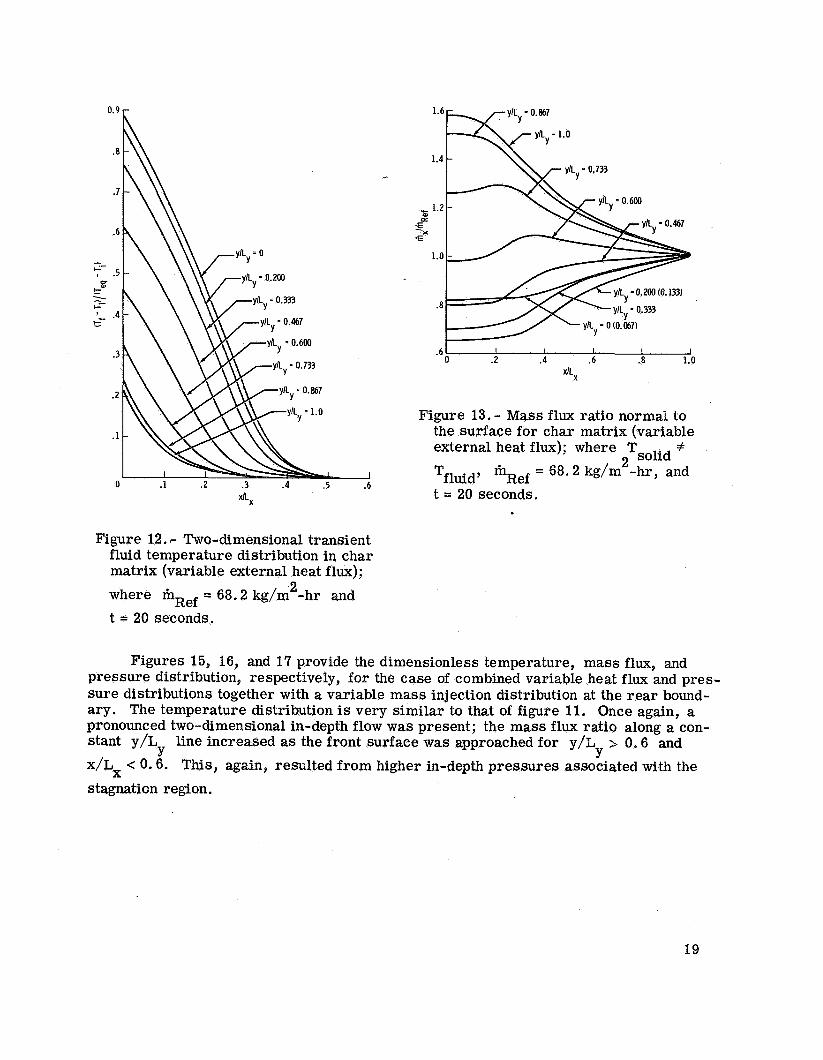
Two-dimensional transient fluid temperature distribution in char 2 matrix (variable external heat flux); where mRef = 68.2 kg/m -hr
and t = 2 0 s e c o n d s . . 19 . . . . . . . . . . . . . . . . . . . . . . . . . n
Mass flux ratio normal to the surface for char matrix (variable z m = 68.2 kg/m -hr, external heat flux); where Tsolid f Tfluid,
and t = 20 seconds. . . . . . . . . . . . . . . . . . . . . . . . . . . 19 Ref
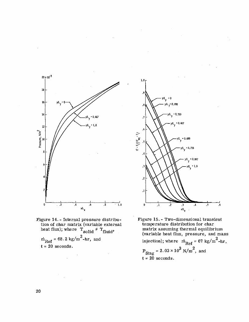
Internal pressure distribution of char matrix (variable external heat m 2 = 68.2 kg/m -hr, and ' Tfluid' Ref flux); where Tsolid
t = 20 seconds . . . . . . . . . . . . . . . . . . . . . . . . . . . . 20
Two-dimensional transient temperature distribution for char matrix assuming thermal equilibrium (variable heat flux, pressure, and mass injection); where m Ref 10 N/m2, and t = 20 seconds
2 = 67 kg/m -hr, PStag = 2.03 X
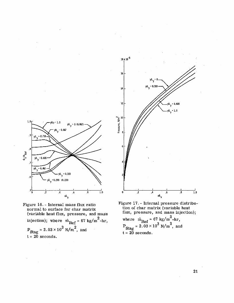
20 3 . . . . . . . . . . . . . . . . . . . . Internal mass flux ratio normal to surface for char matrix (variable
heat flux, pressure, and mass injection); where mRef =
21 3 = 2.03 X 10 N/m2, and t = 20 seconds 2 67 kg/m -hr, PStag . . . . Internal pressure distribution of char matrix (variable heat flux,
n
pressure, and mass injection); where m
'stag
= 67 kg/m"-hr, 21
Ref 3 2 = 2.03 X 10 N/m , and t = 20 seconds . . . . . . . . . . . . .
V
TWO-DIMENSIONAL ANALYSIS OF HEAT AND
MASS TRANSFER IN POROUS MEDIA USING THE
STRONGLY I M P L I C I T PROCEDURE
B y Donald M. C u r r y Lyndon B. Johnson Space Center
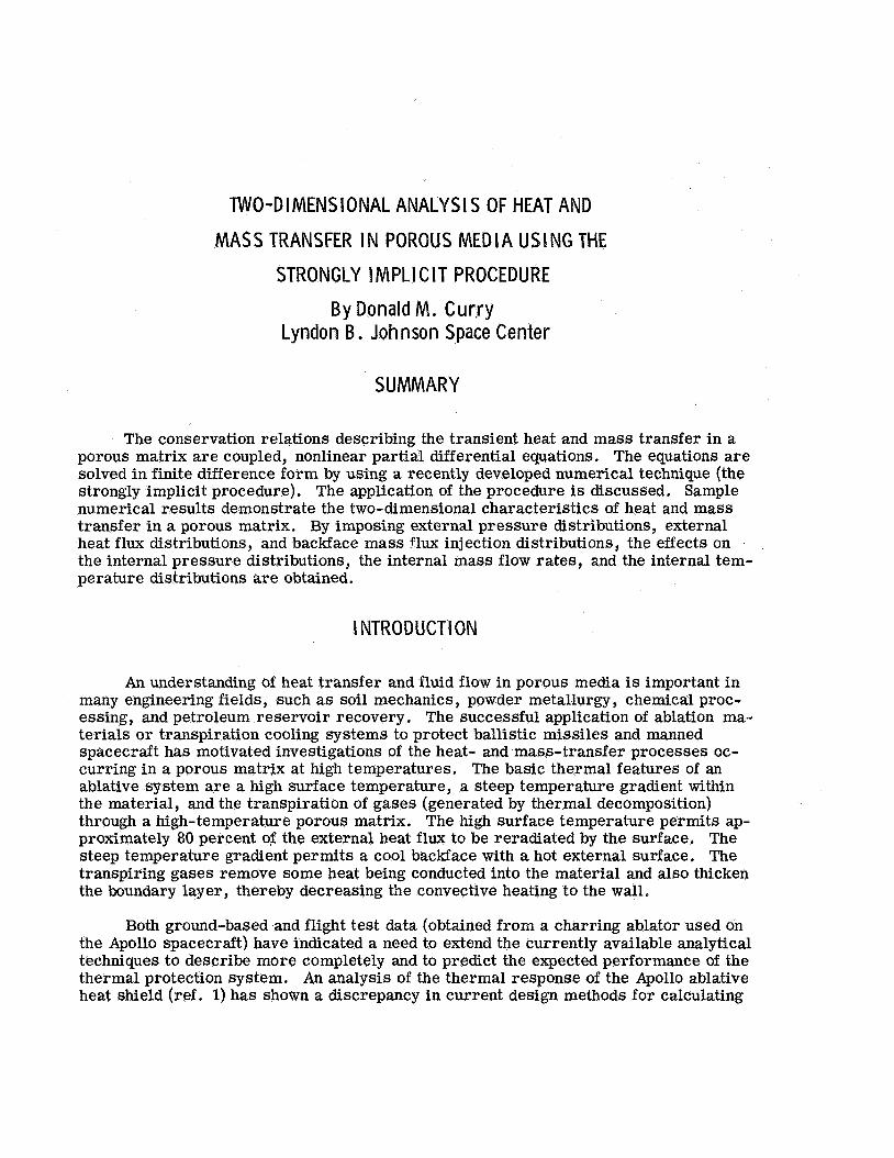
SUMMARY
The conservation relations describing the transient heat and mass transfer in a porous matrix are coupled, nonlinear partial differential equations. The equations are solved in finite difference form by using a recently developed numerical technique (the strongly implicit procedure), The application of the procedure is discussed. Sample numerical results demonstrate the two-dimensional characteristics of heat and mass transfer in a porous matrix. By imposing external pressure distributions, external heat flux distributions, and backface mass flux injection distributions, the effects on the internal pressure distributions, the internal mass flow rates, and the internal tem- perature distributions are obtained.
INTRODUCTION
An understanding of heat transfer and fluid flow in porous media is important in many engineering fields, such as soil mechanics, powder metallurgy, chemical proc- essing, and petroleum reservoir recovery. The successful application of ablation ma- terials or transpiration cooling systems to protect ballistic missiles and manned spacecraft has motivated investigations of the heat- and mass- transfer processes oc- curring in a porous matrix at high temperatures. The basic thermal features of an ablative system are a high surface temperature, a steep temperature gradient within the material, and the transpiration of gases (generated by thermal decomposition) through a high-temperature porous matrix. The high surface temperature permits ap- proximately 80 percent of the external heat flux to be reradiated by the surface. The steep temperature gradient permits a cool backface with a hot external surface. The transpiring gases remove some heat being conducted into the material and also thicken the boundary layer, thereby decreasing the convective heating to the wall.
Both ground-based and flight test data (obtained from a charring ablator used on the Apollo spacecraft) have indicated a need to extend the currently available analytical techniques to describe more completely and to predict the expected performance of the thermal protection system. An analysis of the thermal response of the Apollo ablative heat shield (ref. 1) has shown a discrepancy in current design methods for calculating
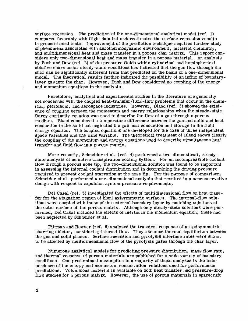
surface recession. The prediction of the one-dimensional analytical model (ref. 1) compares favorably with flight data but underestimates the surface recession results in ground-based tests. Improvement of the prediction technique requires further study of phenomena associated with aerothermodynamic environment, material chemistry, and multidimensional heat and mass transfer in a porous char matrix. This report con- siders only two-dimensional heat and mass transfer in a porous material. An analysis by Bush and Dow (ref. 2) of the pressure fields within cylindrical and hemispherical ablative chars under steady-state conditions has indicated that the gas flow through the char can be significantly different from that predicted on the basis of a one-dimensional model. The theoretical results further indicated the possibility of an influx of boundary- layer gas into the char. However, Bush and Dow considered no coupling of the energy and momentum equations in the analysis.
Heretofore, analytical and experimental studies in the literature a re generally not concerned with the coupled heat-transfer/fluid-flow problems that occur in the chem- ical, petroleum, and aerospace industries. However, Bland (ref. 3) showed the exist- ence of coupling between the momentum and energy relationships when the steady-state, Darcy continuity equation was used to describe the flow of a gas through a porous medium. Bland considered a temperature difference between the gas and solid and heat conduction in the solid but neglected the gas heat conduction and storage in the fluid energy equation. The coupled equations are developed for the case of three independent space variables and one time variable. The theoretical treatment of Bland shows clearly the coupling of the momentum and energy equations used to describe simultaneous heat transfer and fluid flow in a porous matrix.
More recently, Schneider et al. (ref. 4) performed a two-dimensional, steady- state analysis of an active transpiration cooling system. For an incompressible coolant flow through a porous nose tip, the two-dimensional solutiqn was found to be important in assessing the internal coolant distribution and in determining the driving pressure required to prevent coolant starvation at the nose tip. For the purpose of comparison, Schneider et al. performed a one-dimensional analysis that resulted in a nonconservative design with respect to expulsion system pressure requirements.
Del Casal (ref. 5) investigated the effects of multidimensional flow on heat trans- fer for the stagnation region of blunt axisymmetric surfaces. The internal-flow solu- tions were coupled with those of the external boundary layer by matching solutions at the outer surface of the porous matrix. Although only steady-state solutions were per- formed, Del Casal included the effects of inertia in the momentum equation; these had been neglected by Schneider et al.
Pittman and Howser (ref. 6) analyzed the transient response of an axisymmetric charring ablator , considering internal flow. They assumed thermal equilibrium between the gas and solid phases. Surface recession and pyrolysis interface rates were shown to be affected by multidimensional flow of the pyrolysis gases through the char layer.
Numerous analytical models for predicting pressure distribution, mass flow rate, and thermal response of porous materials are published for a wide variety of boundary conditions. One predominant assumption in a majority of these analyses is the inde- pendence of the energy and momentum conservation relations used for performance predictions. Voluminous material is available on both heat transfer and pressure-drop flow studies for a porous matrix. However, the use of porous materials in spacecraft
2

thermal protection systems has emphasized the importance of understanding the b o r e complex, coupled relationship. The general lack of available solutions that consider the coupled energy and momentum relations used in describing the thermal response of a transpiration cooling system motivated this study.
SYMBOLS
cP
hV
K
k
Lx’ Ly
m
m”?
P
9
q”‘
R
T
parameters known from previous time level and previous iteration
functions defined in equation (B3)
coefficients defined in equation (21)
specific heat
gravitational constant
volumetric heat-transfer coefficient
proportionality factor
thermal conductivity
thermal conductivity in x and y directions, respectively
lengthin x and y directions, respectively
mass flow rate, p 3
volume source term
total number of nodes in x direction
total number of nodes in y direction
p r e s sur e
convective heating rate
volumetric heat source (or sink)
universal gas constant
temperature
3

T eq
Ti
T'
t
U
'i, j
V
-c V
Q
P
Y
6
E
P
P
cr
radiation equilibrium temperature
initial temperature
unknown temperature in difference equations
time
total internal energy
velocity in x direction
superficial velocity
intermediate coefficient used in the solution algorithm
velocity in y direction
velocity in a pore
space coordinates
viscous coefficient
inertial coefficient
iteration parameter
dependent-variable difference between the new time step or iteration and the previous time step or iteration
emissivity
viscosity
density
Stefan-Boltzmann constant
viscous stress tensor
viscous dissipation
porosity, ratio of void area to total area
convective heat-blocking ratio due to mass injection
4

Subscripts :
e
f
i
j
0
Ref
Stag
S
W
Superscript :
n
Operators :
('>
v
external
fluid
x-direction node location
y-direction node location
without blockage
reference
stagnation
solid
matrix surface
iteration or time step
indicates parameter at next time step
differential operator
THEORETICAL RELATIONS
The unsteady heat transfer of a compressible gas flowing within a porous matrix can be described by the solution of the conservation equations for mass, momentum, and energy. The fundamental assumption is the use of a continuum model for the porous matrix. Briefly, the volume element used in deriving the conservation equations is assumed large with respect to the individual pores so that the flow field may be con- sidered a continuum. The application of the conservation equations for mass, momen- tum, and energy to the unsteady flow of a gas, with heat transfer, through a porous matrix is presented in appendix A.
5
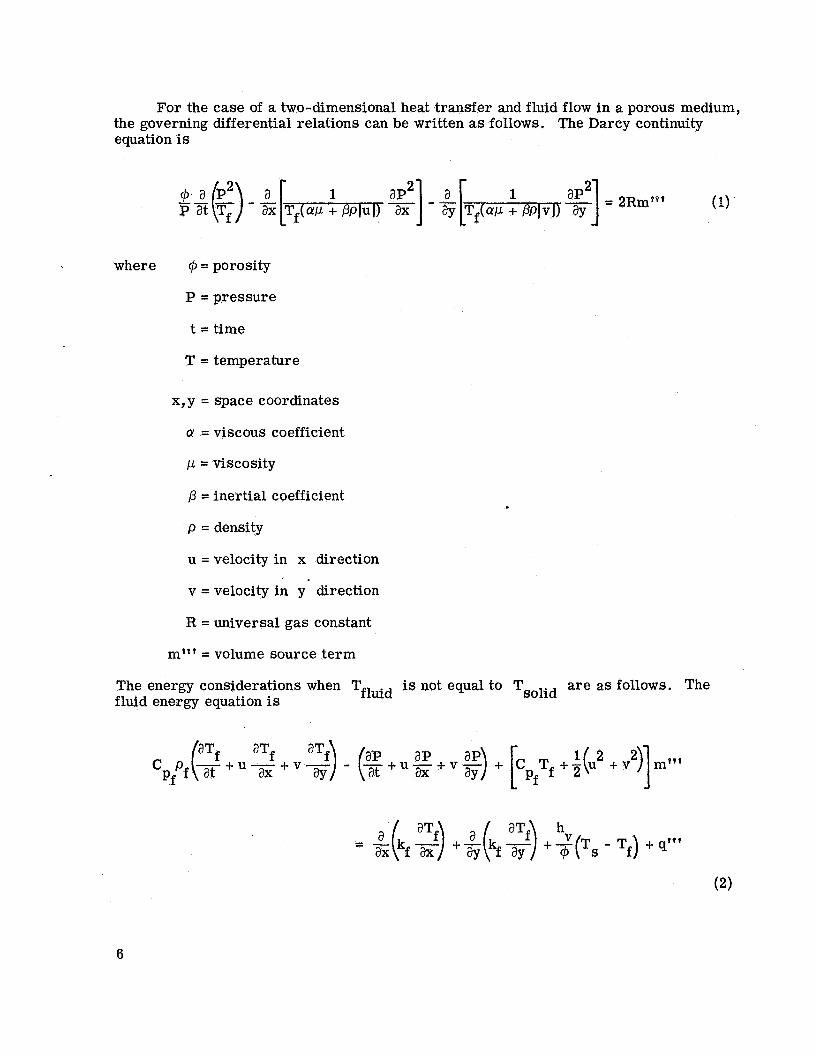
For the case of a two-dimensional heat transfer and fluid flow in a porous medium, the governing differential relations can be written as follows. The Darcy continuity equation is
where @ = porosity
P = pressure
t = time
T = temperature
x,y = space coordinates
cy = viscous coefficient
,u = viscosity
p = inertial coefficient
p = density
u = velocity in x direction
v = velocity in y direction I .
R = universal gas constant
= volume source term m t t '
The energy considerations when Tfluid is not equal to Tsolid are as follows. The fluid energy equation is
aTf a q - (E + u - - + v ~ ) aP + [. T +-(u 1 2 +v2)]m**f c Pf P ( 3 + u T f a t aY a t ax ay Pf f 2 + V -
- a (. aTf) +5 a (. fay +$(Ts - Tf) + q"' -ax fax
6
where C = specific heat P
k = thermal conductivity
hv = volumetric heat-transfer coefficient
q"' = volumetric heat source (or sink)
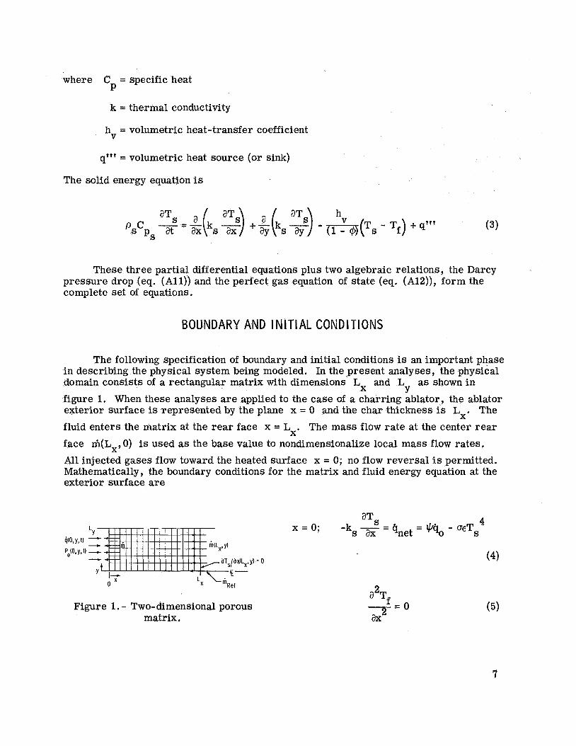
The solid energy equation is
h
ps (3)
These three partial differential equations plus two algebraic relations, the Darcy pressure drop (eq. ( A l l ) ) and the perfect gas equation of state (eq. (A12)), form the complete set of equations.
BOUNDARY AND INITIAL CONDITIONS
The following specification of boundary and initial conditions is an important phase in describing the physical system being modeled. In the present analyses, the physical domain consists of a rectangular matrix with dimensions L and L as shown in figure 1. When these analyses a re applied to the case of a charring ablator, the ablator exterior surface is represented by the plane x = 0 and the char thickness is Lx. The fluid enters the matrix at the rear face x = Lx. The mass flow rate at the center rear face m(Lx, 0) is used as the base value to nondirnensionalize local mass flow rates. All injected gases flow toward the heated surface x = 0; no flow reversal is permitted. Mathematically, the boundary conditions for the matrix and fluid energy equation at the exterior surface are
X Y
Figure 1. - Two-dimensional porous matrix.
a2Tf 2- - 0 (5)
7
where Q = convective heating rate
(T = Stefan-Boltzmann constant
E = emissivity
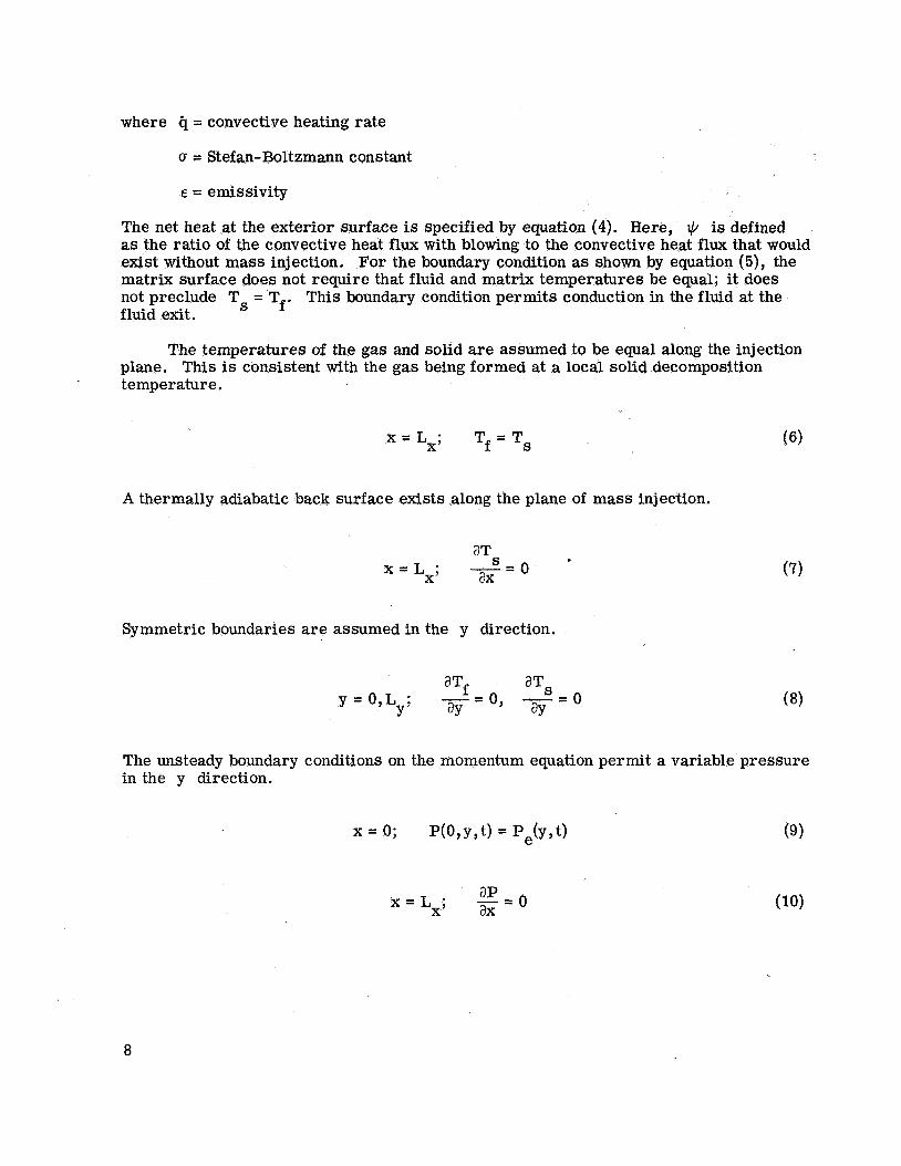
The net heat at the exterior surface is specified by equation (4). Here, IC/ is defined as the ratio of the convective heat flux with blowing to the convective heat flux that would exist without mass injection. For the boundary condition as shown by equation (5), the matrix surface does not require that fluid and matrix temperatures be equal; it does not preclude Ts = Tf. This boundary condition permits conduction in the fluid at the fluid exit.
The temperatures of the gas and solid are assumed to be equal along the injection plane. This is consistent with the gas being formed at a local solid decomposition temperature.
S x = L X ; Tf = T
A thermally adiabatic back surface exists along the plane of mass injection.
- = o aTS ax x = Lx;
Symmetric boundaries are assumed in the y direction.
aTS
Y =O,Ly; ay aY 0, - = o aTf
I-=
The unsteady boundary conditions on the momentum equation permit a variable pressure in the y direction.
- - ap - 0 ax x = Lx;
8

where Pe is external pressure. The boundary condition illustrated by equation (10)
does not permit flow reversal at the injection plane. This is a reasonable assumption since an impermeable seal exists a small distance from the injection zone. Along the y boundary
The initial pressure distribution is assumed constant and equal to the local external pressure at the start of the transient solution. No flow can occur in the y direction along the x = Lx boundary, with symmetrical flow assumed at the boundaries for y = o , y = L y .
Equations (l), (2), and (3) describe the flow and heat transfer in a porous matrix and are coupled, nonlinear partial differential equations. The solution is achieved by approximating the partial derivatives by use of suitable finite difference expressions involving the independent and dependent variables. This procedure leads to a set of algebraic equations in the dependent variable from which the final value can be deter- mined. Three basic finite difference formulas (forward, backward, and central differ- ence) can be used to obtain the necessary relations. Once the finite differencing method has been chosen, a variety of solution techniques is available, each of which has its own peculiar advantages and limitations. For example, an explicit technique may require small integration time steps to ensure stability; the implicit technique seemingly does not have a time-step limitation but may require the solution of a large algebraic matrix.
In this investigation, an implicit central-difference numerical technique is used to obtain solutions for the momentum, energy, and continuity relations; it requires evaluation of the coefficients of the dependent variable at the previous time level and/or iteration as well as the solution of a set of linear difference equations for the dependent variables.
I M PL I C I T D I FFERENC E EQUAT I ON FORMULAT I ON
A general two-dimensional region with an x-y grid system imposed is shown in figure 2. The implicit difference for- mulation used to solve equations (1)’ (2), and (3) can be illustrated conceptually
I!. x,i
Figure 2. - Two-dimensional region with rectangular grid.
9

by consideration of the simpler problem of pure conduction. The transient heat con- duction equation for this two-dimensional region is
An implicit finite difference equation for each grid point (i, j) within the specified region can be written as
. - 2T; . + Ti-l, j] ~ , j + l - 2T;,j + T;,j-l (T;,j - 'i,j) = p+1,~ 2 3 + k pcP X. 1, j (Ax>2 Y i , j (AY?
At
where, for the purposes of this illustration, kx and k
The prime on each temperature represents an unknown temperature. Equation (14) can be written as
have been considered constant. Y
Rewriting equation (15) yields
AT; +BT; . + CTI . C D T I , ~ + ET; .+l =&i,j (16) , j - 1 - Y 3 , 3 ,j 9 3
Equation (16) has five unknown temperatures per grid point (i, j). The values of A, B, C, D, E, and Q are known based on the previous time level and previous iteration. A set of equations similar to equation (16) can be written for all (i, j ) grid points within the region and on the boundaries. This matrix of equations then can be inverted to yield the unknowns T! solution can become very time consuming.
dimensional system proposed by Peaceman and Rachford (ref. 7) reduced the number
For large systems of equations, this matrix l , j *
The development of the alternating direct implicit (ADI) method for the two-
10

of unknowns to three, as obtained for simple one-dimensional problems. Basically, the AD1 solves the equations in one direction while assuming the dependent variable in the second dimension to be constant over the time interval. As an example, consider equa- tion (16) for the first time step, in the x direction.
BTf . + CTf . -I- DTi+l . = Q,., - ATi - ETi - , J , J , J , j -1 , j+l
The temperatures Ti and Ti a re known from the previous time step. Equa- tion (17) yields a tridiagonal matrix.
, j -1 , j + l
A2T1, j + B2T2, j + C2T3, j
*QT2, j -t- B3T3, j + C3T4, j
- Q2,j
= Q3,j
%-lTN-2, j + BN-lTN-l, j + ‘N-lTN,j = &N-1, j
Equation (18) is solved for the unknown temperatures by Gaussian reduction. Then, for the second time step, writing equation (16) in the y direction yields
- , j -1 +CT,! 7 1 . +ET; Y J .+l - Qi, j - BTi-l, j - DTi+l, j AT; (19)
Once again, a tridiagonal matrix as shown by equation (18) is obtained. The advantages of solving a tridiagonal matrix over the matrix generated by equation (16) a re apparent. The AD1 method is not used in this study; rather, the strongly implicit procedure (SIP) is used in the next section.
e
STRONGLY I M P L I C I T PROCEDURE
Recently, Stone (ref. 8) developed a new iterative method for solving sets of alge- braic equations that occur for multidimensional systems. This method is known as the strongly implicit procedure and has been used successfully in solving the two-dimensional, steady-state heat conduction problem as well as multidimensional flow in a petroleum reservoir. The foundation of the SIP calculation method lies in the approximate factor- ing of the five-diagonal matrix (five nonzero elements in each row of matrix) generated by equation (16) into three-diagonal upper and lower triangular matrices. The detailed
11

mathematical matrix reduction process, required to derive the upper and lower trian- gular matrices, is presented by Stone (ref. 8) and more recently by Bozeman (ref. 9).
The process of defining the upper and lower matrices involves the temperatures of the grid point (i, j). As shown in figure 3, the modified matrix equation involves not only the grid points indicated by the solid circles but also the temperatures at grid points (i-1, j+ l ) and (i+l, j-1) shown by the open circles.
The influence of these new temperatures in the modified equation is balanced par- tially by subtracting approximately equal terms. The modified equation for the unknown side of equation (16) becomes
i-1 i+l
Figure 3. - Grid model for definition of upper and lower matrices.
= % , j
where y is the iteration parameter. The first five terms are simply the original left side of equation (16)’ and the H.
eratures at (i-1, j + l ) and (i+l, j-1).
G. are used to cancel partially the temp- 1, j’ 1, j
The equations used in this algorithm for SIP are
Bi, j c. = 1 , j 1 + yfi-l,
. = b. .e Hi , j i , j i , j - l
Gi,l . = c. 1, j f i - l , j
12
Di,j - ‘Hi , j e. =
1 , j di, j
, j Ei,j - rGi -
f i , j - di, j
and
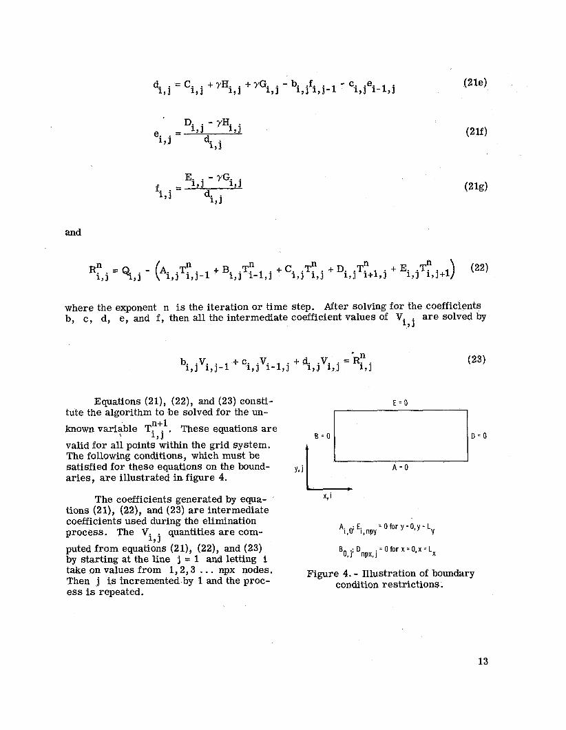
n . + C Tn n R n . =€I+. - (A. i,j .Tn i , j - l +Bi , jTi- l ,J 1, J ,J i , j i , j + D i , j T i + l , j + E i , j T i , j + l
where the exponent n is the iteration or time step. After solving for the coefficients b, c, d, e, and f , then all the intermediate coefficient values of Vi are solved by
, j
(23) - ’ n bi .Vi + c. .v. + di, jVi, - Ri, , J , j - 1 1 , ~ 1-1,j
Equations (21), (22), and (23) consti- tute the algorithm to be solved for the un- known variable Ti . These equations are valid for all points within the grid system. The following conditions, which must be satisfied for these equations on the bound- aries, are illustrated in figure 4.
n+l , j
The coefficients generated by equa- tions (21), (22), and (23) are intermediate coefficients used during the elimination process. The Vi quantities are com- puted from equations (21), (22), and (23) by starting at the line j = 1 and letting i take on values from 1,2,3 . . . npx nodes. Then j is incremented by 1 and the proc- ess is repeated.
, j Y
Ai,o; Ei,npy = 0 for y =O,y = L
= 0 for x = 0,x Lx j; Dnpx, j
Figure 4. - Illustration of boundary condition restrictions.
13
After all Vi coefficients have been generated and stored, equation (24) is , j
solved for 6:" by simply reversing the order; that is, starting with i = npx and j =npy. , j
n+l . - f. .6"1 i , j6 i+ l , j i , j i , j + l
n+l 6i,j = Vi,j - e.
- Tn n+l = Tn+l where 6
n = iteration or time step
n+l = 2.T - T'
Therefore, the values of temperature at the new time level (n+l) can be calculated from a knowledge of T at the current time level (n). Stone (ref. 8) recommends a variation of the procedure by carrying out the calculation just described in reverse order on each alternate time step. This has the effect of using the temperatures
on the odd steps. 'i-1, j + l and Ti+l, j - 1
The value of the iteration parameter y lies between 0 and 1. The minimum value is not critical and could be zero; however, Stone states that the maximum value can be critical for obtaining convergence. For a heat conduction problem with constant prop- erties, Stone recommends
It should be pointed out that equation (25) is for a particular problem, and it may be necessary to vary y for other types of problems to determine its effect. In this work, a constant y value of 0.95 was used successfully. The SIP formulation as applied to a simplified form of the fluid energy equation (2) is presented in appendix B.
SOLUTION TECHNIQUE
The two-dimensional nonlinear conservation equations ( l ) , (2), and (3) were ap- proximated by a set of finite difference equations compatible with Stone's algorithm. These equations are linearized by holding the nonlinear coefficients constant for each iterative calculation. The coefficients are then updated after each iteration. This set of linear equations is solved by application of equations (21) to (24). Because the equations are coupled through the nonlinear coefficients, the following iterative scheme was used as shown in figure 5.
14

Figure 5. - Numerical iteration procedure.
The procedure is (1) to solve the solid energy equation by using the previous level values for flow rates, temperature, and physical properties; (2) to solve the Darcy continuity equation to obtain new pressures and velocities; (3) to obtain the fluid energy equation solution by using these latest values for flow rate, pressure, and temperature to obtain new fluid temperatures; and (4) to perform an independent calculation of the continuity equation (eq. (Al)) to ensure mass conservation. Three iterations per time step normally were required to obtain a satisfactory mass balance. The largest
e r ror occurs at the surface node where the pressure is being specified. Gas density for this node is evaluated from the continuity equation instead of the perfect gas law.
NUMER I CAL RESULTS
The solution is capable of describing a wide variety of physical situations; how- ever, only a limited number of representa- tive cases are presented. More complete parametric comparisons for the porous ma- tr ix are provided in reference 10. Numeri- cal results are provided for cases similar to those experienced by the Apollo configu- ration. The external pressure distribution, the external heat flux distribution, and the backface mass flux injection distribution are shown in dimensionless form in fig- ure 6. The external distributions (mass flux injection at the rear boundary x =
pressure and heat flux at the external bound- a ry x = 0) were not time dependent in the cases under discussion. To identify the flow characteristics in the porous media, the decoupled solution (isothermal solution) is considered first. The effects of heat transfer on the internal flow characteristics are then considered by solving the coupled, two-dimensional equations.
Lx9
1.00
.75
m
Z .50 L a
.25
0
1.0
.a
c
.6 -E .E -
m ..- .g .4 .(J
. 2
0 I I I I I
.2 .4 .6 .8 1.0
YILy
Figure 6. - External pressure gradient, heat flux, and mass injection flux ratios used to simulate typical Apollo conditions; where P = P(O,O), Staff -
= Q(0,0), and mRef = m(Lx, 0). %tag
15
4~~hermal Solutions
A metallic matrix material is considered for examples of isothermal solutions. For the metallic matrix, the porosity Cp is 0.42, the viscous coefficient cy is
10 -2 4 -1 1.619 X 10 m , and the inertial coefficient /3 is 1.634 X 10 m . If the Darcy continuity equation (eq. (1)) is solved for an isothermal case, the
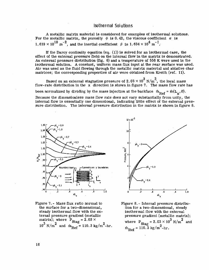
effect of the external pressure field on the internal flow in the matrix is demonstrated. An external pressure distribution (fig. 6) and a temperature of 556 K were used in the isothermal solution. A constant, uniform mass flux input at the rear surface was used. Air was used as the fluid flowing through the metallic matrix material and ablative char matrices; the corresponding properties of air were obtained from Kreith (ref. 11).
Based on an external stagnation pressure of 2.03 X 10 N/m ', the local mass flow-rate distribution in the x direction is shown in figure 7. The mass flow rate has
been normalized by dividing by the mass injection at the backface m = m(Lx,O). Because the dimensionless mass flow rate does not vary substantially from unity, the internal flow is essentially one dimensional, indicating little effect of the external pres- sure distribution. The internal pressure distribution in the matrix is shown in figure 8.
3 2
Ref
1.05 ylLy - 0.9
IL = 1.0 1.04 Y
1.a
1.02 yIL = 0.5 Y
1.01
%j 1.00
.99
LL *E -
.9a Boundary layerm ,-Symmetry on y boundaries
I I I I 0 .2 .4 .6 .a 1.0
xllX
Figure 7. - M a s s flux ratio normal to the surface for a two-dimensional, steady isothermal flow with the ex- ternal pressure gradient (metallic matrix); where PStag = 2.03 x
10 N/m 3 2 2 and mRef = 110.3 kg/m -hr.
I I I I I I
xlLx
0 .2 .4 .6 .a 1.0
Figure 8. - Internal pressure distribu- tion for a two-dimensional, steady isothermal flow with the external pressure gradient (metallic matrix);
0 0
= 2.03 X lo3 N/m& and where PStag 2 m = 110.3 kg/m -hr. Ref
16
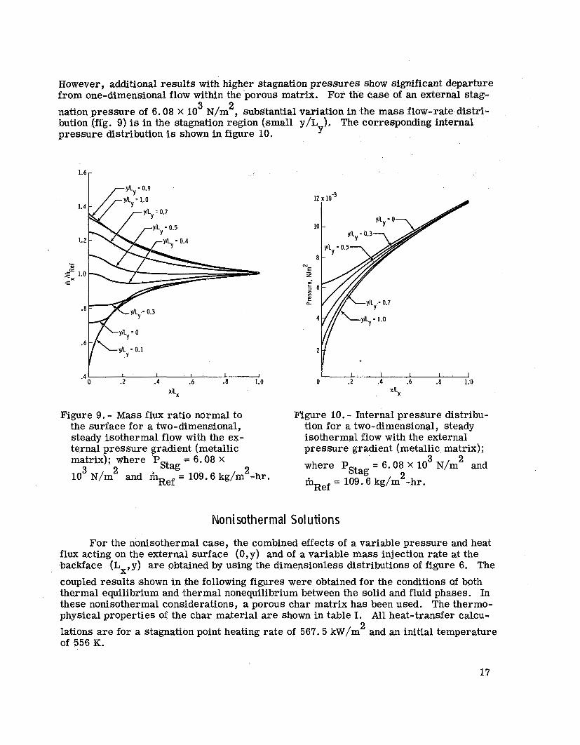
However, additional results with higher stagnation pressures show significant departure from one-dimensional flow within the porous matrix. For the case of an external stag- nation pressure of 6.08 X 10 N/m2, substantial variation in the mass flow-rate distri- bution (fig. 9) is in the stagnation region (small y/L ). The corresponding internal
3
pressure distribution is shown in figure 10. Y
.4 ' I I 1 I 1 I I I I I I 0 .2 .4 .6 .a 1.0 0 .2 .4 .6 .8 1.0
x/LX x%
Figure 9. - Mass flux ratio normal to the surface for a two-dimensional, steady isothermal flow with the ex- ternal pressure gradient (metallic matrix); where P = 6.08 X
10 N/m
Figure 10. - Internal pressure distribu- tion for a two-dimensional, steady isothermal flow with the external pressure gradient (metallic matrix);
= 6.08 X 10 N/m and where PStag m = 109.6 kg/m -hr.
3 2 2 2 3 2 Stag
and mRef = 109.6 kg/m -hr. Ref
No ni sother mal Sol u tio n s
For the nonisothermal case, the combined effects of a variable pressure and heat flux acting on the external surface (0,y) and of a variable mass injection rate at the backface (Lx,y) are obtained by using the dimensionless distributions of figure 6. The coupled results shown in the following figures were obtained for the conditions of both thermal equilibrium and thermal nonequilibrium between the solid and fluid phases. In these nonisothermal considerations, a porous char matrix has been used. The thermo- physical properties of the char material are shown in table I. All heat-transfer calcu- lations are for a stagnation point heating rate of 567.5 kW/m and an initial temperature of 556 K.
2
17
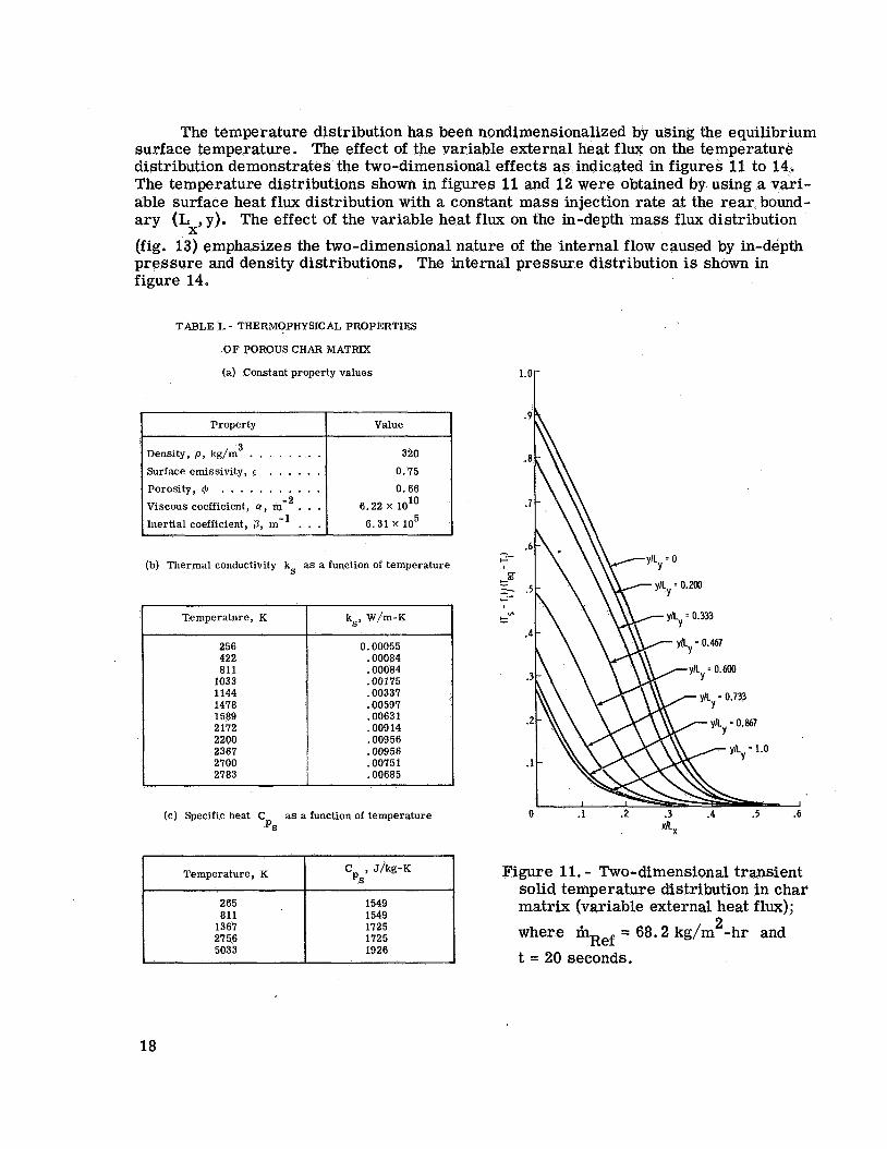
figure 14.
~ ~~
Property
TABLE I. - THERMOPHYSICAL PROPERTIES
O F POROUS CHAR MATRIX
(a) Constant property values
Value
Density, p, kg/m . . . . . . . . Surface emissivity, E . . . . . . Porosity, Q . . . . . . . . . . . viscous coefficient, u , m-2 . . . Inertial coefficient, 0, m- . . . 6.31 X lo5
6.22 x lolo
(b) Thermal conductivity ks a s a function of temperature
Temperature, K
256 422 811 1033 1144 1478 1589 2172 2200 2367 2100 2183
The temperature distribution has been nondimensionalized by using the equilibrium surface temperature. The effect of the variable external heat flux on the temperature distribution demonstrates the two-dimensional effects as indicated in figures 11 to 14. The temperature distributions shown in figures 11 and 12 were obtained by using a vari- able surface heat flux distribution with a constant mass injection rate at the rear bound- ary (Lx, y). The effect of the variable heat flux on the in-depth mass f lux distribution (fig. 13) emphasizes the two-dimensional nature of the internal flow caused by in-depth pressure and density distributions The internal pressure distribution is shown in
ks, W/m-K
0.00055 .00084 .00084 .00175 .00337 .00597 .00631 .009 14 .00956 .00956 .0075 1 .00685
(c) Specific heat C as a function of temperature PS
I 1 C , J/kg-K P s I Temperature, K
1125 2156 1725 5033 1926
1.0
.9
.a
.7
.6 - G-
e= 5 .5 .- I-
Ln I- -
.4
.3
.2
.1
0 .1 .2 .3 .4 .5 .6
a x
Figure 11. - Two-dimensional transient solid temperature distribution in char matrix (variable external heat flux); where m = 68.2 kg/m -hr and t = 20 seconds.
2 Ref
18
0.9
.a
.7
.6
.5
.4
.3
.2
.1
0 .1 .2 .3 .4 .5 .6
xlLx
tl-
t 5 G-
P
e-
1.6
1.4
1.2
1.0
.a
.6 0 .2 .4 .6 .a 1.0
xILx
Figure 13.- Mass flux ratio normal to the surface for char matrix (variable
Tfluid, mRef = 68.2 kg/m -hr, and t = 20 seconds.
external heat flux); where Tsolid f 2
Figure 12.7 Two-dimensional transient fluid temperature distribution in char matrix (variable external heat flux); where m = 68.2 kg/m -hr and t = 20 seconds.
2 Ref
Figures 15, 16, and 17 provide the dimensionless temperature, mass flux, and pressure distribution, respectively, for the case of combined variable heat f lux and pres- sure distributions together with a variable mass injection distribution at the rear bound- ary. The temperature distribution is very similar to that of figure 11. Once again, a pronounced two-dimensional in-depth flow was present; the mass flux ratio along a con- stant y/L line increased as the front surface was approached for y/L > 0.6 and x/L < 0.6. This, again, resulted from higher in-depth pressures associated with the
stagnation region.
Y Y X
19
20 10-3
la -
16 -
14 -
12 -
I I I I I 0 .2 .4 .6 .a 1.0
Figure 14. - Internal pressure distribu- tion of char matrix (variable external heat flux); where Tsolid f Tfluid,
2 m = 68.2 kg/m -hr, and t = 20 seconds.
Ref
1.0
.9
.a
.7
.6 - r.r-
CT
e" 2 .5 G-
!=
.4
. 3
.2
. I
0 .1 .2 . 3 .4 .5 .6 XkX .
Figure 15. - Two-dimensional transient temperature distribution for char matrix assuming thermal equilibrium (variable heat flux, pressure, and mass injection); where mRef = 67 kg/m -hr, 2
= 2.03 x 10 3 N/m 2 , and 'stag t = 20 seconds.
20
1.0
.9
.8 ..- CT .E *E -
.7
.6 yIL -0.200 10.133)
Y
I I I I I 0 .2 .4 .6 .8 1.0
.5
Figure 16. - Internal mass flux ratio normal to surface for char matrix (variable heat flux, pressure, and mass injection); where niRef = 67 kg/m -hr,
'Stag t = 20 seconds.
2
3 2 = 2.03 X 10 N/m , and
N E z - E 2 E n
I
I I I I d .2 .4 .6 .8 1.0
Figure 17. - Internal pressure distribu- tion of char matrix (variable heat flux, pressure, and mass injection); where m = 67 kg/m -hr,
'stag = 2.03 X 10 N/m , and t = 20 seconds.
2 2 Ref
21

~ONCLUDING REMARKS
The flow of a compressible gas through a porous matrix externally heated at the fluid exit surface has been investigated. The physical model was formulated to simu- late the flow of a pyrolysis gas formed during the degradation of an ablative material. The formulation of a numerical solution to the coupled energy, mass, and momentum relations describing this multidimensional flow of gas through a high-temperature porous matrix has been achieved. Two-dimensional coupled solutions were obtained using the strongly implicit procedure.
In this study, the strongly implicit procedure has been successfully applied to the solution of a system of coupled, nonlinear partial differential equations. The numerical results indicate the significance of multidimensional flow for both isothermal as well as nonisothermal effects in a porous material subjected to nonuniform boundary conditions.
Lyndon B. Johnson Space Center National Aeronautics and Space
Houston, Texas, January 986- 15-31-04-72
Administration 11, 1974
22

APPENDIX A
DER IVATIO PJ OF THEORETICAL RELATIONS
The basic conservation relations for mass, energy, and momentum are applied to a compressible gas flowing through a high-temperature porous matrix. A continuum is assumed to exist in the porous matrix.
CONSERVATION OF M A S S
The continuity equation for the unsteady flow of a single-species gas with a source term is
where the superficial fluid velocity vf = Cpv' and v' is velocity in a pore.
CONSERVATION OF MOMENTUM.
The conservation of momentum based on Newton's second law of motion is
where 7 is the viscous stress tensor and g is the gravitational constant. Direct application of this equation to flow in porous media has been discussed by Whitaker (ref. 12). boundary conditions makes the solution of equation (A2) unfeasible.
The viscous force term v . 7 was evaluated experimentally by Darcy (ref. 13)
The inability to specify exactly the flow geometry of the porous matrix and
for slow, steady incompressible flow. These assumptions yield
23
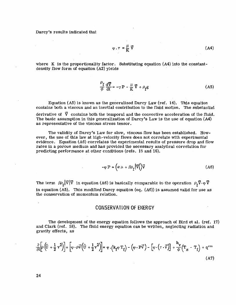
Darcy's results indicated that
v . 7 = E T K
where K is the proportionality factor. Substituting equation (A4) into the constant- density flow form of equation (A2) yields
Equation (A5) is known as the generalized Darcy Law (ref. 14). This equation contains both a viscous and an inertial contribution to the fluid motion. The substautial derivative of T contains both the temporal and the convective acceleration of the fluid. The basic assumption in this generalization of Darcy's Law is the use of equation (A4) as representative of the viscous stress tensor.
The validity of Darcy's Law for slow, viscous flow has been established. How- ever, the use of this law at high-velocity flows does not correlate with experimental evidence. Equation (A6) correlates the experimental results of pressure drop and flow rates in a porous medium and has provided the necessary analytical correlation for predicting performance at other conditions (refs. 15 and 16).
4 -
The term PpflV/V in equation (A6) is basically comparable to the operation pfT.vT in equation (A5). This modified Darcy equation (eq. (A6)) is assumed valid for use as the conservation of momentum relation.
~ O N ~ E R V A ~ ~ O N OF ENERGY
The development of the energy equation follows the approach of Bird et al. (ref. 17) and Clark (ref. 18). The fluid energy equation can be written, neglecting radiation and gravity effects, as
24

where 6 is the total internal energy. Equation (A8) is obtained by performing the in- dicated differentiations on the left side of equation (A7), substantial derivative, and using the mechanical energy
the definition of the
where @ is viscous dissipation. Using the continuity equation (eq. (Al)) and the defini- tion of enthalpy, equation (A8) may be written, neglecting viscous dissipation for a perfect gas, as
dTf dP pfcpf dt - dt +
which is equation (2) in the
h ( C Pf T f + - v : ") m t " = v * (A9)
text.
ENERGY EQUATION FOR SOLID
Application of the law of energy conservation to the solid state yields
which is equation (3) in the text.
REDUCTION OF GOVERNING EQUATIONS
The pressure, flow rate, and temperature distributions in a porous medium are obtained by a simultaneous solution of equations (Al), (A6), (A9), and (AlO), in conjunc- tion with an equation of state and the boundary and initial conditions. However, it is possible to reduce the number of equations by combining Darcy's Law and the continuity equation.
25
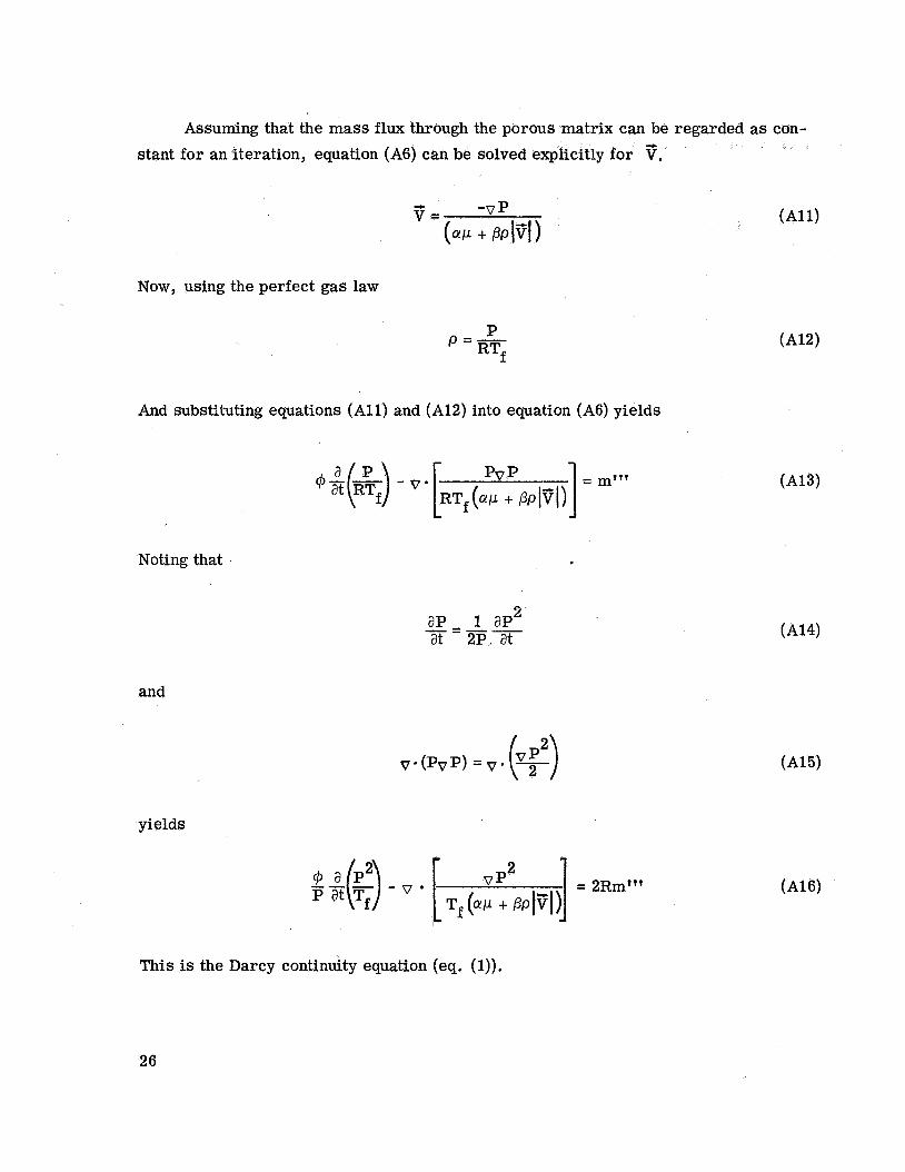
Assuming that the mass flux through the porous matrix can be regarded as con- stant for an iteration, equation (A6) can be solved explicitly for 3.
Now, using the perfect gas law
P p =- RTf
And substituting equations ( A l l ) and (A12) into equation (A6) yields
Noting that
ap 1 ap2 at 2 ~ . at
-=--
and
yields
This is the Darcy continuity equation (eq. (1)).
26
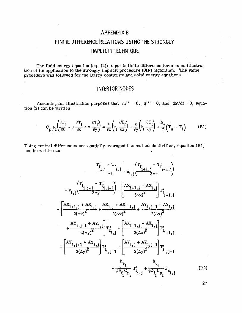
APPENDIX B FINITE DIFFERENCE RELATIONS USING THE STRONGLY
I M P L I C I T TECHNIQUE
The fluid energy equation (eq. (2)) is put in finite difference form as an illustra- tion of its application to the strongly implicit procedure (SIP) algorithm. The same procedure was followed for the Darcy continuity and solid energy equations.
I NTER I OR NODES
Assuming for illustration purposes that m"' = 0, q"' = 0, and dP/dt = 0, equa- tion (2) can be written
(B1)
Using central differences and spatially averaged thermal conductivities, equation (Bl) can be written as
- [mi+l,j + mi + mi,j + mi-l,.j + , j + l + Ayi , j AYi
2( AX)^ AX)^ 2(AY )2
h h

where
k kfx and AY=- fY
m=T P C Pf Pf
Formulating equation (B2) as
AT; +BT; . + C T i ,J . +DTl+l , j + ETI , j+ l 2: Qi,j (B4) , j - 1 - 9 1
(which is equation (16)) requires that
u. . + Axi . - 1J + ? 3 AX)^ Bi, j - 2Ax
U. - - =i+l , j + Ax; , j + 1 , j Di, j AX)^ 2Ax
28

As an illustration of the boundary condition requirements, consider the heated surface at x = 0, y = 0 (fig. 4). The SIP boundary restrictions require A = B = 0. Therefore, equation (B4) becomes
CTI Y J . +DTl+l Y J . +ET,! 2 1 .+l = Qi,j
where the boundary conditions
- ? 1
, j - 1 - Ti, j+l -= 0 or Ti’ aY
and
a2Tf - = o
2 ax
have been used.
29
REFERENCES
1. Curry, Donald M. ; and Stephens, Emily W. : Apollo Ablator Thermal Performance at Superorbital Entry. NASA TN 0-5969, 1970.
2. Bush, Harold G. ; and Dow, Marvin B. : Multidimensional Gas Flow Through Per- meable Char Layers and Its Effects on Ablation. NASA TR R-296, 1969.
3. Bland, D. R. : Mathematical Theory of the Flow of a Gas in a Porous Solid and of the Associated Temperature Distributions. Proc. Roy. SOC. (London), A, 221, 1954, pp. 1-28.
4. Schneider, P. J.; Mauer, R. E.; and Strapp, M. G. : Twa-Dimebsional Tran- spiration Cooling. AIAA Paper No. 69-96, 1969.
5. Del Casal, E. P. : The Effects of Multidimensional Flow Through Porous Matrices in Mass Transfer Cooling. AIAA Paper No. 69-149, 1969.
6. Pittman, Claud M. ; and Howser, Lona M. : Numerical Analysis of the Transient Response of an Axisymmetric Ablative Char Layer Considering Internal Flow Eff,ects. NASA TN D-6895, 1972.
7. Peaceman, D. W. ; and Rachford, H. W. : The Numerical Solution of Parabolic and Elliptic Differential Equations. J. SOC. Ind. Appl. Math., v01. 3, 1955, pp. 28-41.
8. Stone, Herbert L. : Iterative Solution of Implicit Approximations of Multidimen- sional Partial Differential Equations. SIAM J. Numerical Analysis, vol. 5, no. 3, Sept. 1968, pp. 530-558.
9. Bozeman, J. D. : Numerical Solutions for Recirculating Flow in a Cavity. Ph. D. Dissertation, Univ. of Houston, 1971.
10. Curry, Donald Morgan: Multi-Dimensional Analysis of Heat and Mass Transfer in Porous Media. Ph. D. Dissertation, Univ. of Houston, 1970.
11. Kreith, Frank: Principles of Heat Transfer. International Textbook Co., 1958, p. 535.
12. Whitaker, S. : The Equations of Motion in Porous Media. Chem. Eng. Sci., vol. 21, Mar. 1966, pp. 291-300.
13. Darcy, H. : Les Fontaines Publiques de la Ville de Dijon. 1856.
14. Yih, Chia-shun: Dynamics of Nonhomogeneous Fluids. Macmillan, 1965, pp. 196-199.
15. Green, Leon, Jr.; and Duwez, Pol: Fluid Flow Through Porous Metals. J. Appl. Mech., vol. 18, Mar. 1951, pp. 39-45.
30
16. Greenberg, D. B,; and Weger, E. : An Investigation of the Viscous and Inertial Coefficients for the Flow of Gases Through Porous Sintered Metals with High Pressure Gradients. Chem. Eng. Sei., vol. 12, no. 1, 1960, pp. 8-19.
17. Bird, Robert Byron; Stewart, Warren E. ; and Lighffoot, Edwin N. : Transport Phenomena. John Wiley & Sons, Inc., 1964.
18. Clark, R. K. : Flow of Hydrocarbon Gases in Porous Media at Elevated Tempera- tures. M. s. Thesis, Univ. of Virginia, 1968.
NASA-Langley 5-382 31
NATIONAL AERONAUTICS AND SPACE ADMINISTRATION WASHINGTON, D.C. 20546
OFFICIAL BUSINESS PENALTY FOR PRIVATE USE $300 SPECIAL FOURTH-C LASS
BOOK RATE
POSTAGE AND FEES P A I D N A T I O N A L AERONAUTICS AND
SPACE ADMINISTRATION 451
POsTMAST~R : If Undeliverable (Section 158 Postal Manual) Do Not Return
“The aeronautical and space activities of the United States shall be conducted so as to contribute . . . to the expansion of human knowl- edge of phenomena in the atmosphere and space. The Administration shall provide for the widest practicable and appropriate disseminution of information concerning its activities and the results thereof.”
-NATIONAL AERONAUTICS AND SPACE ACT OF 1958
NASA SCIENTIFIC AND TECHNICAL PUBLICATIONS TECHNICAL REPORTS: Scientific and technical information considered important, complete, and a lasting contribution to existing knowledge.
TECHNICAL NOTES: Information less broad in scope but nevertheless of importance as a contribution to existing knowledge.
TECHNICAL MEMORANDUMS : Information receiving limited distribution because of preliminary data, security classifica-
TECHNICAL TRANSLATIONS: Information published in a foreign language considered to merit NASA distribution in English.
SPECIAL PUBLICATIONS: Information derived from or of value to NASA activities. Publications include final reports of major projects, monographs, data compilations, handbooks, sourcebooks, and special bibliographies.
tion, or other reasons. Also includes conference proceedings with either limited or unlimited distribution.
CONTRACTOR REPORTS: Scientific and technical information generated under a NASA contract or grant and considered an important contribution to existing knowledge.
mILiZATION PUBLICATIONS: Information on technology used by NASA that may be of particular interest in commercial and other. non-aerospace applications. Publications include Tech Briefs, Technology Utilization Reports and Technology Surveys.
Details on the availabilify of these publications may be obtained from:
SCIENTIFIC AND TECHNICAL INFORMATION OFFICE
N A T I O N A L A E R O N A U T I C S A N D SPACE A D M I N I S T R A T I O N Washington, D.C. 20546