nasa technical note tn d-7532 technical note nasa tn d-7532 n cr3 ub ... government accession no. ....
TRANSCRIPT
I ! NASA TECHNICAL NOTE NASA TN D-7532
N Cr3 ub
STRAIN-CYCLING FATIGUE BEHAVIOR OF TEN STRUCTURAL METALS TESTED IN LIQUID HELIUM (4 K), IN LIQUID NlTROGEN (78 K), AND IN AMBIENT AIR (300 K)
by Alfred J. Nuchtigall
Lewis Research Center Cleveland, Ohio 44135
N A T I O N A L AERONAUTICS A N D SPACE At ,MINISTRATION W A S H I N G T O N , D. C. FEBRUARY 1974
https://ntrs.nasa.gov/search.jsp?R=19740008106 2018-06-15T21:06:08+00:00Z

1. Repoct No. NASA TN D-7532
STRUCTURAL METALS TESTED IN LIQUID HELIUM (4 K), IN LIQUID NITROGEN (78 K), AND IN AMBIENT AIR (300 K)
9 Performing Organization Name and Address
Lewis Research Center National Aeronautics and Space Administration
2. Government Accession No.
. February 1974 6. Performing Orgmization Code
7. Author(*)
Alfred J. Nachtigall
11. Contract or Grant No.
3 .ecipient's Catalog No.
8. Performing Organ~zat~on Report No.
E-7613 10. Work Unit No.
I 5. Supplementary Notes
Cleveland, Ohio 44135 2. Sponsoring Agency Name and Address
National Aeronautics and Space Administration Washington, D. C. 20546
6 Abstract
Strain-cycling fatigue behavior of 10 different structural alloys and metals was investigated in liquid helium (4 K), is liquid nitrogen (78 K), and in ambient a i r (300 K). At high cyclic lives, fatigue resistance increased with decreasing temperature for a l l the materials investigated. At low cyclic Lives, fatigue resistance generally decreased with decreasing temperature for the materials investigated. Only for Inconel 718 did fatigue resistance increase with decreasing temperature over the entire life range investigated. Comparison of the experimental f a t i y e behavior with that predicted by the Manson method of universal slopes showed that the fatigue behavior of these materials can be predicted for cryogenic temperatures by using material tensile properties obtained a t those same temperatures.
13. Type of Repon and Period Covered
Technical Note 14. Sponsoring Agency Code
7. Key Words (Suggested by Authorls) J
Cryogenic fatigue; Strain cycling; Low-cycle fatigue; Fatigue life predictions; Mechanical properties; Axial fatigue; Liquid nitrogen; 1,iquid helium
' For sale by the Nat~onal Technical lnformat~on Serv~ce. Spr~ngf~eld. V ~ r g ~ n ~ a 22151
18. D~stribut~on Statement
Unclassified - unlimited
Cat. 17
Unclassified I Unclassified I 31 $3.00
9 . Security Classif. (of this report) 20. Security Classif. (of this page) I 21. No. of Pager 1 22 Rice*

STRAIN-CYCLING FATlGlJE BEHAVIOR OF TEN STRUCTURAL METALS TESTED
I N LIQUID HELIUM (4 K), I N LIQUID NITROGEN (78 K),
AND I N AMBIENT AIR (300 K)
by Alfred J. Nachtigall
Lewis Research Center
SUMMARY
The strain-cycling fatigue behavior of 10 different structural alloys and metals (two aluminum alloys, two titanium alloys, two stainless steels, a maraging steel, a high- nickel alloy, pure nickel, and pure copper) was investigated in liquid helium (4 K), in liquid nitrogen (78 K), and in ambient a i r at room temperature (300 K). Cylindrical hourglass-shaped specimens were loaded in compression and tension about zero mean strain to produce the desired strain ranges. Tensile properties were also obtained for each material and environmental temperature so that they could be used with the method of universal slopes to predict the fatigue behavior a t each temperature.
At high cyclic fatigue lives, fatigue resistance increased with decreasing tempera- ture for all the materials investigated. At low cyclic fatigue lives, fatigue resistance generally decreased with decreasing temperature fcr the materials investigated. Only for Inconel 718 did the fatigue resistance increase with decreasing temperature over the entire life range investigated. Comparison of experimental fatigue behavior with that predicted by the Manson method of universal slopes s h ~ l ~ e t i that the strain-cycling fatigue behavior of these materials s t cryogenic temperatures 2F.n be predicted with an accuracy comparable to that achieved in earlier investigations conducted at room temperature. Eighty percent of the fatigue data obtained a t cryogenic t ~ ~ m p e r a t u r e ~ -7sre predicted within a life factor of 3.
INTRODUCTION
It is well known that cryogenic temperatures can markedly affect the fatigue behav- ior, a s well a s the mechanical properties, of structural alloys and metals. Most inves-
tigations of the effect of cryogenic temperatures on the fatigue strength of materials have been conducted under load cycling conditions resulting in high cyclic lives (ref. 1). An earlier fatigue investigation at the NASA Lewis Research Center (ref. 2) was also conducted at cryogenic temperatures under load cycling. The higher loading conditiom used in reference 2 resulted in much shorter cyclic lives (low-cycle fatigue). Strain- controlled low-cycle fatigue data on materials a t cryogenic temperatures a r e scarce and limited to liquid nitrogen temperatures (ref. 3).
The high cost and complexity of testing apparatus, a s well a s the limited availability and high cost of cryogenic fluids, make prediction of fatigue behavior a t cryogenic tem- peratures desirable. Prior to this investigation, no known efforts had been made to do so. However, at room temperature, correlation of strain-controlled low-cycle fatigue data with applied cyclic strain and tensile properties of materials has been extensively verified.
The Manson method of universal slopes was developed for predicting room- ~amperature fatigue behavior (ref. 4) by utilizing easily obtained tensile properties (ul- timate tensile strength, elastic modulus, and ductility). It is reasonable to expect that the method could also be used to predict fatigue behavior a t cryogenic temperatures by using the necessary tensile prorerties obtained a t cryogenic temperatures. However, the method correlates cyclic fatigue life with applied cyclic &rain (rather than the applied cyclic s t ress used in most investigations). Therefore, hardly any existing cryogenic fa- tigue data could be used to determine the validity and suitability of the method of univer- sal slopes for predicting the fatigue behavior of structural materials a t cryogenic tem- peratures.
An experimental investigation was therefore conducted at the NASA Lewis Research Center to obtain strain-controlled low-cycle fatigue data on 10 different structural alloys and metals tested in liquid helium, in liquid nitrogen, and in ambient a ir . The observed experimental fatigue behavior of these materials could then also be compared with the fatigue behavior predicted by the method of universal slopes. Hence, the mechanical properties necessary for applying the prediction method were also determined for each material and temperature.
The units for physical quantities used in this report a r e given in the International System of Units (SI); however, measurements during the investigation were made in U. S. customary units. Factors relating these two systems of units a r e given in refer- ence 5; those pertinent to the present investigation a r e presented in the appendix.

MATERLALS, APPARATUS, AND TEST PROCEDURE
Materials and Specimens
Most of the materials investigated were considered to have potential use a t cryo- genic temperatures. They included cyclically strain-hardening materials such as the two stainless steels AISI 304L and AISI 310; the nickel-base alloy Inconel 718; unalloyed nickel 270; and oxygen-free, high-conductivity (OFHC) copper. Also included were cyclically strain-softening materials such as the two aluminum-base alloys 2014-T6 and 2219-T851; the two titanium-base alloys Ti-5Al-2.5Sn and Ti-6A1-4V; and a 300- grade, 18-percent-nickel, maraging steel produced by consumable electrode vacuum melting. The chemical composition of these alloys is given in table I. The condition of each of the materials before they were tested is listed in table XI.
Specimens from each material investigated were fabricated from wrought bar stock 2.54 centimeters in diameter, with one exception. The 2219-T851 aluminum specimens were fabricated from extruded bar stock, 2.54 centimeters square. Specimen geometry is shown in figure 1. All specimens had 2.54-centimeter -diameter button heads on each end for attachment to the loading columns. Tensile specimens (fig. l (a)) had a 2.54- centimeter gage length with a 0.635-centimeter test section diameter. Fatigue speci- mens (fig. l(b)) had a shape similar to an hourglass with a minimum test section aiam- eter of 0.635 centimeter. Specimens for determining Poisson's ratio and elastic modulus (fig. l(c)) had a square test section, 0.897 centimeter on each side and 5.1 cen- t imeters long. The flat faces were desirable for cementing strain gages to them.
Test Apparatus
Tensile tests. - Tensile tests were conducted in ambient a i r (300 K) and in liquid nitrogen (78 K) with conventional universal testing machines. The cryostat used to con- tain the liquid nitrogen that surrounded the test specimen during tensile tes ts was essen- tially a double-walled vacuum-insulated cylindrical vessel open a t the top. The lower loading column entered through the bottom by means of a cryogenic fluid seal. Tensile tests in liquid helium (4 K) were conducted in the cryostat and the closed-loop electro- hydraulically actuated testing machine used for conducting fatigue tests in liqujd helium (see Fatigue tests). This machine possessed several features that made it suitable for conducting tensile tests. One feature was that the closed-loop command signal from the function generator could be manually triggered to initiate the various waveforms from zero output voltage, going either positive o r negative as desired. A second feature m s that one of the function generatorts selectable waveforms was a linear ramp signal.

This signal could be interrupted at any point on the ramp with a "ramp hold" switch and held a t that level until the ramp hold switch was returned to i ts normal "run" position and the ramp resumed its rise. For these tensile tests, loading was ..pplied by means of the linear ramp signal from the function generator controlling displacement of the loading column at a linear rate with respect to time. The rates varied from 1.0 to 3.8 milliineters per minute depending on the expected elongation of the material tested.
Fatigue tests. - Fatigue tests were conducted in either of two closed-loop electro- - hydraulically actuated fatigue testing machines. The first machine, shown in figure 2, was designed and built at the Lewis Research Center, for the most part from commer- cially available components. Its highest practical cycling rate was 1.2 hertz. Its max- imum load range was 59000 newtons.
The second fatigue machine was a commercial model of a closed-loop electrohy- draulically actuated fatigue machine capable of a cycling rate of 33 hertz with a hydraulic actuator double-amplitude di.splacement of 1.22 millimeters. The hydraulic actuator was also capable of developing cyclic load amplitudes of *90@3 newtons.
Each testing machine was equippcd with a cryostat specifically designed and built for NASA for this investigation. Although the basic design for the two cryostats was the same, experience with the first cryostat dictated several desian improvements in the cryostat used with the second machii~e, which is illustrated in figure 3. It consisted of a vacuum-tight enclosure (I) that surrounded a cylindrical specimen test chamber (N) vhose axis was concentric with the specimen loading axis and the cylindrical vacuum jacket (I). The specimen test chamber contained the cryogenic fluid in which the speci- men (0) was immersed during tests. To allow access to the test specimen, the cylindri- cal specimen chamber parted at the middle of i t s axial length by means of a circumfer- ential solder seal (G). The lower half of the seal had a circumferential well (or trough) to hold the low-temperature solder, which was melted by an integral electric heater (P) whenever the seal had to be made or broken. The upper and lower loading columns (L)
were brought through the opposite ends of the chamber with a double bellows arrange- ment (Q). The concentric double bellows arrangement allowed opening the two halves of the chamber f a r enough to install a test specimerr. It also allowed relative motion be- tween the upper and lower loading columns during tests without placing loads on the chamber itself.
Split couplings (F) engaged the button head on each end of the specimen to the button head on the end of each loading column in the specimen chamber. All axial clearance between the engaging button heads was taken up by a pair af opposing wedges (H) drawn against each other by means of machine nuts on threaded studs extending from the nar- row edge of each wedge through each half of the split coupling.
The radiation shield (J) in the vacuum space between the specimen chamber and the outer vacuum jacket consisted of telescoping copper cylinders attached to the upper and

lower loading columns. When tests were conducted with liquid helium in the specimen chamber, the radiation shield was cooled with liquid nitrogen. The lower cylinder was cooled by liquid nitrogen from the radiation shield reservoir (E) flowing through the coil of copper tubing (K) soldered to i ts outer surface. The larger diameter copper cylinder in the midsection of the cryostat was fastened by thumbscrews to the underside of the radiation shield reservoir containing liquid nitrogen. It was cooled by conduction through interface contact between i ts mounting flange and the reservoir. And it could be lowered inside the lower section of the vacuum jacket to allow access to the specimen chamber. The upper inside edge of the radiation shield reservoir was fastened to the upper loading column.
Elastic constants. - The apparatus for determining the elastic modulus and Pois- son's ratio in ambient air (300 K) and in liquid nitrogen (78 K) was a deadweight creep machine. Fixed loads were applied to the specimens by placing weights on the weight pan. Applied specimen loads were measured with a load cell and associated equipment. The specimen loading train went through an ope^^-mouth dewar surrounding the specimen, with the lower loading cnlumn from the specimen extending through the bottom of the dewar. The dewar could be filled with liquid nitrogen, thus immersing the specimen while load and strain determinations were made for that environmental temperature. The apparatus used for determining the elastic constants in liquid helium was the same cryostat and electrohydraulically actuated testing machine used for conducting tensile and fatigue tests in liquid helium.
Instrumentation. - A tensile extensometer was used to measure the elongation of the specimen's test section between 25.4-millimeter gage marks during the early part of each tensile test. The displacement sensing element was a linear variable differential transformer (LVDT) calibrated for the environmental use temperature. The extensom- eter used with tensile tes ts in liquid helium is shown in figure 4.
A diametral extensometer was used to sense the cyclic diameter changes of the minimum test section of specimens during fatigue tests. Figure 5 shows the extensom- eter mounted on a specimen. Again the displacement sensing element was an LVDT calibrated in the use environment.
The boiling temperature of liquid nitrogen enveloping a test specimen was measured with a calibrated platinum resistor and recorded on a strip-chart recorder. The boiling temperature of liquid helium enveloping a test specimen was measured with a calibrated carbon resistor tied to the specimen test section. Calibrations were traceable to NBS standards .
For Poisson's ratio measurements, dimensional changes due to loading of the speci- mens for each material were measured with foil strain gages cemented to the flat faces. A strain gage was cemented on each face of one pair of opposite parallel faces with the elements parallel to the specimen loading axis. On the adjacent pair of opposite parallel
faces the elements of the strain gages cemented to each face were normal to the loading axis of the specimen. An additional pair of s t rain gages was cemented to the faces of a dummy block of the same material that had faces the eame width a s those of the spe- cimen. The pair of strain gages on the dummy block was used with either pair of gages sensing longitudinal or transverse dimension changes of the specimen. They were con- nected a s a Wheatstone bridge, and strain changes were determined using a commercial strain indicator, The dummy block and its strain gages were placed in the same en- vironment a s the specimen used to measure elastic modulus and Poisson's ratio to avoid temperature effects.
Test Procedure
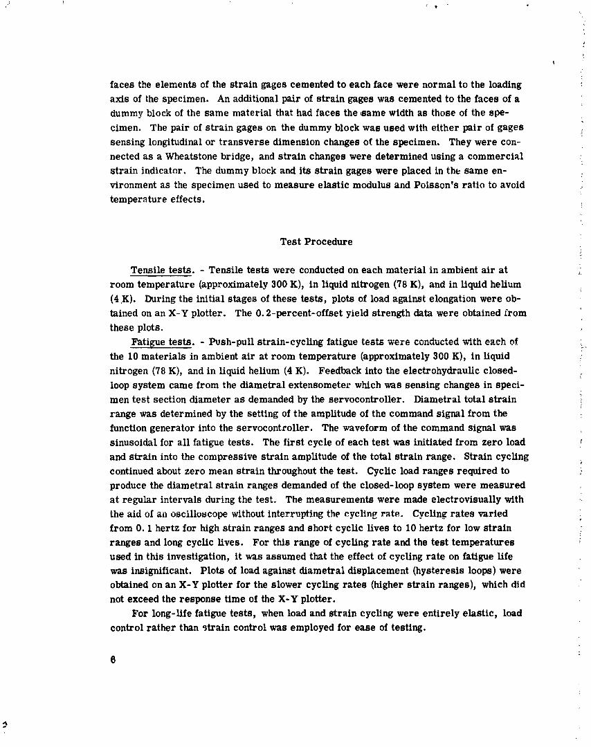
Tensile tests. - Tensile tests were conducted on each material in ambient a i r a t room temperature (approximately 300 K), in liquid nitrogen (78 K), and in liquid helium (4 ,K). During the initial stages of these tests, plots of load against elongation were ob- tained on an X-Y plotter. The 0.2-percent-offset yield strength data were obtained irom these plots.
Fatigue tests. - Push-pull strain-cycling fatigue tests were conducted with each c?f the 10 materials in ambient air a t room temperature (approximately 300 K), in liquid nitrogen (78 K), and in liquid helium (4 K). Feedback into the electrohydraulic closed- loop system came from the diametral extensometer which was sensing changes in speci- men test section diameter as demanded by the servocontroller. Diametral total strain range was determined by the setting of the amplitude of the command signal from the function generator into the servocontroller. The waveform of the command signal was sinusoidal for a l l fatigue tests. The f i rs t cycle of each test was initiated from zero load and strain into the compressive strain amplitude of the total strain range. Strain cycling continued about zero mean strain throughout the test. Cyclic load ranges required to produce the diametral strain ranges demanded of the closed-loop system were measured a t regular intervals during the test. The measurements were made electrovisually with the aid of an oscilloscope without interrupting the cycling rate. Cycling rates varied from 0 . 1 hertz for high strain ranges and short cyclic lives to 10 hertz for low strain ranges and long cyclic lives. For this range of cycling rate and the test temperatures used in this investigation, i t was assumed that the effect of cycling rate on fatigue life was insignificant. Plots of load against diametral displacement (hysteresis loops) were obtained on an X-Y plotter for the slower cycling rates (higher strain ranges), which did not exceed the response time of the X-Y plotter.
For long-life fatigue tests, when load and strain cycling were entirely elastic, load control rather than strain control was employed for ease of testing.

Elastic constants. - Determination of elastic modulus and Poisson's ratio for each material and temperature required measurement of longitudinal and transverse strains with each increment of load. Strain data were obtained from a t least two increasing- decreasing load histories. Care was taken to avoid exceeding the proportional limit for each material.
DATA ANALYSIS LlND FATIGUE LIFE PREDICTIONS
Fatigue Data Analysis
The basic raw data obtained from each test were the cyclic fatigue life, the con- trolled diametral total strain range, and the applied load range at the half-life. The s t ress range a t the half-life was calculated by using the load range at the half-life with the test cross-sectional a r ea a t the s ta r t of the test.
The longitudinal elastic strain range was calculated from s t r e s s range a t half-life and the elastic modulus. Determination of longitudinal plastic strain range was made from the following equation:
where
AE strain range
1 Poisson's ratio
L longitudinal
D diametral
t total
e elastic
p plastic
The longitudinal total &train range is the sum of longibdinal elastic and plastic s t rain ranges.
Low- Cycle Fatigue Life Prediction
Low-cycle fatigue life predictions were made by the method of universal slopes

from reference 4, which can be expressed by the following equations:
where
"u ultimatk tensile strength, M N / ~ ~
Nf number of fatigue cycles to failure - E elastic modulus, GN/m 2
D tensile ductility, In 100 100 - RA
RA reduction of area, percent
Equation (2b) describes the elastic component of the longitudinal total strain range. For higher cyclic fatigue lives i t becomes the dominant quantity. For any fixed cyclic life it varies a s the ratio of the material tensile properties a,/E varies.
Equation (2c) describes the plastic component of longitudinal total strain range. It becomes the dominant quantity at the lower cyclic fatigue lives. Fo r any fixed cyclic life i t varies with tensile ductility of the material to the 0.6 power.
The values of tensile properties used to predict a strain-range - fatigue-life curve for each material a t each of the environmental test temperatures were those determined from tensile tests a t the same temnerature.
RESULTS AND DISCUSSION
Mechanical and Tensile Properties
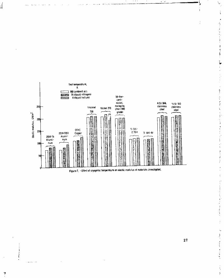
Mechanical propertiee of the 10 materials investigated a r e summarized in table III. Some of these results a r e also presented in bar graph form in figures 6 to 8. Figure 6 shows that the ultimate tensile rctrength increased with decreasing temperature for all the materials investigated. The highest initial ultimate tensile strength, that of the 18-percent-nickel maraging steel, increased 35 percent with decreasing temperature to 4 K. But the lowest initial ultimate tensile strength, that of OFHC copper, had a
Fatigue Behavior
!
103 percent increase with decreasing temperature. The greatest increase with decreas- !
Results from strain-cycling fatigue tests on the 10 materials investigated a t the three different temperatures a r e summarized in table IV. Long-Life load cycling fatigue tests a r e noted in the table.
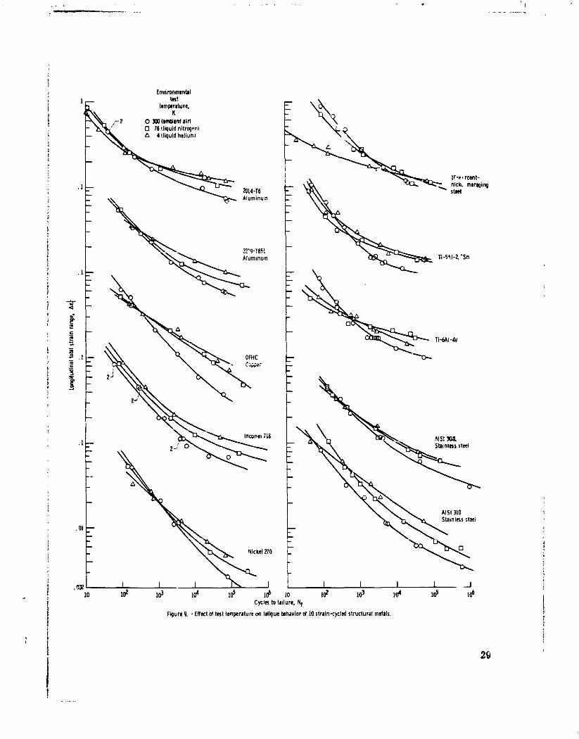
Effect of cryogenic temperature on fatigue -- behavior. - Plots of total longitudinal s t rain range against experimental cyclic fatigue life are presented in figure 9 for each material and environmental test temperature. The plots show that for the lower cyclic strain ranges (higher cyclic lives) the fatigue resistance of a l l 10 materials investigated improved with decreasing cryogenic temperature. The observed trend of the tempera- ture effect on fatigue resistance is consistent with what might be expected by using the Manson method of unive sal slopes. This effect is evident from equation (2b). For high cyclic fatigue lives the elastic component of total strain n n g e is dominant and varies a s
O" /E increases with decreasing temperature, thus predicting a higher fatigue resistance.
For the higher cyclic strain ranges (lower cyclic lives) there is a reversal in fatigue behavior for most of the materials investigated. The general trend is for fatigue resist- ance to decrease with decreasing temperature (fig. 9). For al l the materials investi- gated, except Inconel 718, the fatigue resistance in liquid helium was generally less than in ambient a ir , and for a majority of the materials tine fatigue resistance in Liquid helium was less than that in liquid nitrogen at the lower cyclic lives. For Inconel 718, the dt igue resistance increased with decreasing temperature over the entire span of strain range investigated. For AISI 310 stainless steel and 2219-T851 and 2014-T6 aluminum
I
ing temperature was 182 percent for AISI 304L stainless steel. The trend of a slight increase in the elastic modulus with decreasing cryogenic tem-
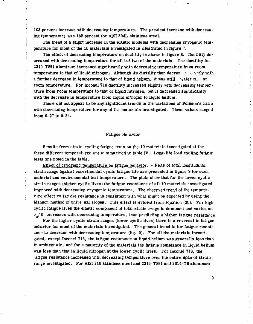
perature for most of the 10 materials investigated is illustrated in figure 7. The effect of decreasing temperature on ductility is shown in figure 8. Ductility de-
creased with decreasing temperature for a l l but two of the materials. The ductility for 2219-T851 aluminum increased significantly with decreasing temperature from room temperature to that of liquid nitrogen, Although its ductility then decrea; r . . ,L .:'*tly with a further decrease in temperature to that of liquid helium, it wao still -eater tt. ..II a t room temperature. For Xnconel718 ductility increased slightly with decreasing temper- ature from room temperature to that of liquid nitrogen, but it decreased significantly with the decrease in temperature from liquid nitrogen to liquid helium.
There did not appear to be any significant trends in the variations of Poisson's ratio with decreasing temperature for any of the materials investigated. These values ranged from 0.27 to 0.34.

the fatigue resistance increased in liquid nitrogen over that in ambient a i r a t room tem- perature over the entire span of strain range investigated. However, in liquid helium there was a crossover and the fatigue resistance became lower a t the higher strain ranges (lower cyclic lives) than in liquid nitrogen and ambient a ir .
The Manson method of universal slopes would ,e expected to predict decreasing fa- tigue resistance with decreasing temperature a t low cyclic fatigue life, where the plastic strain component is the dominant quantity for materials whose ductility decreases with decreasing temperature. This become^ evident from equation (2c), where the plastic strain range varies with tensile ductility to the 0.6 power. A g ~ o d example is the fatigue behavior of 18-percent-nickel, maraging steel (300 grade) shown in figure 9. The large drop in fatigue resistance in liquid helium a t lower cyclic lives can be attributed to the large drop in tenaile ductility of this material in iiquid helium.
Comparison of experimental with predicted fatigue behavior. - Comparison of ob- served experimental fatigue behavir - with that predicted by the Manson method of univer - sal slopes is presented in figure 10. Nearness of a data point to the 45" line is a meas- ure of how well the Manson methor' 9 universal slopes can predict the experimental data. The dot symbols represent the a. . from previous research on 29 different materials tested in ambient a i r (ref. 4). It can be seen that all the data from the present investi- gation fall well within the scatterband of the ear l ier data from reference 4. Eighty per- cent of the fatigue data generated at cryogenic temperatures in this investigation fall within a predicted life factor of 3, a s shown by figure 10. It is clearly evident from these reaults that th? Manson method of universal slopes can therefore be used to predict the fatigue behavior of materials at cryogenic temperatures, as well as at room tempera- ture, when the material tensile properties used a r e determined a t the same temperature for which the fatigue resistance predictions a r e to be made.
SUMMARY O F RESULTS
The strain-cycling fatigue behavior of 10 different alloys and metals (two aluminum alloys, two titanium alloys, two stainless steels, a maraging steel, a high-nickel alloy, pure nickel, and pure copper) was obtained in liquid nitrogen (78 K) and in liquid helium (4 K). Their fatigue behavior was also obtained in ambient a i r a t room temperature (300 K) for purposes of comparison. The major results a r e summarized as follows:
1. At high cyclic fatigue lives, where the elastic component of strain range is dom- inant, fatigue resistance increased with decreasing temperature for a l l the materials investigated.
2. Conversely, a t low-cyclic fatigue Wee, where the plastic component of strain range is dominafit, fatigue resistance decreased with decreasing temperature for most

of the materials investigated. Only for Inconel 718 did the fatigue resistance increase with decreasing temperature over the entire life range investigated.
3. The Manson method of universal slopes can be used to predict the strain-cycling fatigue behavior of these materials at cryogenic temperatures with a degree of accuracy a s good a s that achieved in an earlier inveetigation conducted a t room temperature. In a comparison of experimental with predicted fatigue behavior, 80 percent of the fatigue data generated a t cryogenic temperatures in this investigation were predicted within a life factor of 3.
Lewis Research Center, National Aeronautics snd Space Administration,
Cleveland, Ohio, Septemkr 19, 1973, 501-21.

1 APPENDIX - CONVEK 43N OF THE INTERNATIONAL SYSTEM OF ITNITS '8 r
TO U. S. CUSTOMARY UNITS 3 I
The International System of Uuits (SI) was adopted by the Eleventh General Confer- s
ence of Wcights and Measures in Pzris, October 1960. Conversion factors for the units I used herein are from reference 5 and are presented in the following table:
Conversion factor U. S. customary unit I ib) I
Prefix Multiple m
Frequency Force
Length Stress
Temperature
1 mega (M)I $ 1 gigs ( G )
b ~ u l t i p l y value given i n Si units by ronver! ion factor to obtain equivalent value in U. S. custon~ary its o r apply conversion formula.
a ~ r e f i x e s to indicate multiples of SI units a r e a s follows:
hertz ( J z ) newton (N)
meter (m)
newton/meter
( ~ i m ~ ) kelvin (K)
1 .0 0.2248
39.37 l . 4 5 ~ 1 0 - ~
OF = 2 (K - 255.4) 5
C P S lbf in.
ksi = 1000 lkf/in. 2
degree Fahrenheit (OF)

REFERENCES
1. Schwartzberg, F. R. ; Osgood, S. H. ; Herzog, R. G. ; and Kiefer, T. F. : Cryogen- i c Materials Data Handbook (Revised). Martin Co. (AFML-TDR-64-280, AD- 609562), Aug. 1968.
2. Nachtigall, Alfred J. ; Klima, Stanley J. ; and Freche, John C. : Fatigue of Liquid Rocket Engine Metals at Cryogenic Temperatures to -452' F (4' K). NASA TN D-4274, 1967.
3. Feltner, C. E. ; and Laird, C. : Cyclic Stress-Strain Response of F. C. C. Metals and Alloys - I. Phenomenological Experiments. Acta Met., vol. 15, no. 10, Oct. 1967, pp. 1621-1632.
4. Manson, S. S. : Fatigue: A Complex Subject - Some Simple Approximations. Exper- imental Mech., vol. 5, no. 7, July 1965, pp. 193-226.
5. Committee on Metric Practice: ASTM Metric Practice Guide. ASTM Standard E 380-72, 1972.

TA
BL
E I
. - C
HE
MIC
AL
CO
MP
OSI
TIO
N O
F M
AT
ER
IAL
S T
ES
TE
D
All
oyin
g an
dJoy
re
sid
ual
el
emen
ts
2014
-T6
alu
- m
inum
22
19-T
851
alu
min
um
O
FH
C C
OP
-
wr
Mat
eria
l
Nic
kel
270
18
-per
cen
t-
nic
kel
m
arag
ing
stee
l 30
0 gr
ade
Ti-
5A
1-2.
5Sr
-
.--
6.1
.0
2
----
--
----
--
----
--
----
--
.07
.0
069
----
--
----
--
----
--
.or1
--
----
. 1
24
----
--
----
--
----
--
----
--
Bal
ance
4
.2
----
--
----
--
----
--
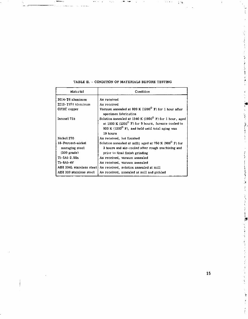
TABLE II. - CONDITION OF MATERIALS BEFORE TESTING
Material
2014-T6 aluminum 2219-Tb51 aluminum OFHC copper
Inconel 716
Nickel 270 18-Percent-nickel
nlaraging steel (300 grade)
Ti-5A1-2.5Sn Ti-6A1-4V AISI 304L stainless steel AISI 310 stainless steel
Condition
As received As rcceived Vacuum annealed at 920 K (1200' F) for 1 hour after
specimen fabrication Solution annealed a t 1340 K (1950' F) for 1 hour, aged
at 1000 K (1350' F) for 9 hours, furnace cooled to 920 K (1200' F), and held until total aging was 19 hours
As received, hot finished Solution annealed a t mill; aged a t 750 K ( 9 0 0 ~ I?) for
3 hours and air-cooled after rough machining and prior to final finish grinding
AS received, vacuum annealed As received, vacuum annealed As received, solution annealed at mill As received, annealed at mill and pjckled
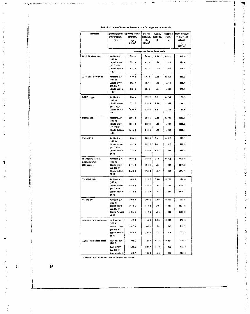
TABLE Ol. - MECHANICAL PROPERTlLB OF MATERIAIS TEETED
U . l e r h l Envtronmental Ultlmlt. Ienslle EIIItlc Trruii . Puimsm's YMld s b e d h Wst tempera- s t n w i h , modulu. ductlllty, n l i o , (0.2 percent
lure Ou* E. D li offnt), M N ~ G N ~
2014-T6 alumlnum Ambient a l r
I300 K) Llquld nltro-
Llquld hellum 14 Kl
2219-1'851 alunllnum Amblent a l r
(500 KI ~ q u l d nitro. gan (78 K ) Liquld hellun
, (4 K!
OFHC copper Ambient a l r
Uquld hellum
(4 K)
l w m l 718 Amblent a i r I (300 K)
Llquld nltro- gem (78 K) Llquid hellum
(4 K!
Nlckel 270 Amblent a i r
(300 K) Liquid nitro-
6Cn (70 K) Liquid h?llum
(4 K)
I&Percmt-nickel Amblent a i r mnraglw steel (300 K) (300 Era&) Liquid nitro-
gen (78 K) Liquld helium ( 4 K)
Ti-5.41-2.5% Amblent a t r
(300 K) Llquld nltrn-
pen (78 KI Llquid hellum
(4 K!
TI-8AI-4V Amblent a i r (300 K) Llquld nltro-
gen (18 K) Llquld W l u m
AlSl 304L stalnlesa steel ' Amblcnt a l r (300 KI Liquid nitro- gen PI8 Kl Llquld hellunl (4 K1 1 A W m ~ e - steel 1 Z r j Uquld nllro-
Llquld hrllulll
a ~ a l n c d wltll hourglass-shaped f a l l y e specimens.
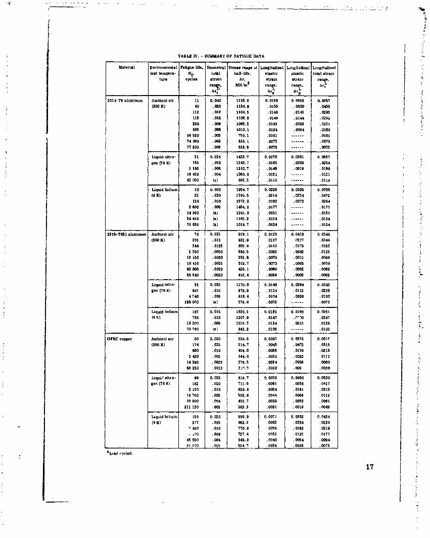
TABLE N. - SMMARY OF FATlCUE DATA
Snvlronmenta tell tempera-
ture
Amblcnt alr (SW K)
m & l l u d l ~ l ehrtic s t n i n range.
0,;
0,0159 .0155 .0148 .0149 .0143 .0134 .0101 . 0075 . M)?Z
Llquld nttro-
gen 0 8 K)
- -
31 0.024 165 ,010
1 180 .008 19 430 .w4 WWO (3)
&n$ltiidlml p b t l c r t n l n
range,
A(,"
0 0698 .WOO ,0145 .Old4 .0088 .W34
------ ------ .-----
Liquid bllur (4 K)
Longltudlna total strain
range,
A$
0.OPSI .0455 . 0203 .0293 .0231 .0168 .0101 . ms .W72
10 U.030 23 .020
124 .010 2800 .OMI
14 880 (a) 24 410 (a) 71 mo (a)
AmMent air (300 K)
-- Liquid nitro- gen (I u K)
l q u i d heltur (4 K)
Ambient alr (300 K)
89 182
2 150 18 750 33 BOO
211 120
Liquid hellur (4 K)
'Luad cycled.

TABLE IV. - Contlnucd. SUMMARY OF FATIGUE DATA - Iamelral
total Ltraln range, q -
0.040 ,040 ,020 ,020 ,008 ,008 ,004 .m ,004 . O(D ,002 . w
0.040 .020 ,008 ,004 ,002 -
0.040 . a 0 ,008
(a 1
nYLranmenh en! temwra-
lure
Ambient alr (300 Kl
Wquld hellur (4 K)
18-Percat-nlckc marrglng steel 1300 grade)
Ambient alr (300 Kl
Uquld nitro- ten Pr8 K)
Llquld hellur (4 10

TABLE IV. - Continued. SUMMARY OF FATIGUE DATA
.ongttudlnal plnntlc rtraln r a m . A$
0.0011 .MI9 . OS23 .W03 .W84 ,0029 . 0021 . w 4 .W15 .0014 . ow3
AmMent a l r (300 I0
Ligvld nltro- sen (78 K)
Uquld hcilun (4 K)
43 0.040 3088. 9 126 .016 2157.2 ass . o i u zse5.s 382 .014 2592.4 515 .014 2518.3
1 250 .W8 2414.9 10 580 .W46 2141.5 38 360 .DO4 1705.0 60 800 .M)4 1754.1
52 0.040 3592.2 128 . m 0 3025.4 275 .020 3171.6 R34 .OlO 2933.1
3 9YU .We 2644.8 6120 1 .005
1892.6 64 510 (a) 1857.5
Llgvld nltro- v n (78 K)

TABLE 1V. - Concluded. SUMMARY OF FATIGUE DATA
!nvlronrnental +st tempera-
ture
angihdlnnl Longitudinal pllsllc total mtraln
mY1 ranfp Art A6
P
0.0358 0.0435 ,0266 .0329 ,0173 .0224 .W82 .0115 .W82 .0116 .0084 .0115 .me . m 2 .0008 .WSO
0.0321 0.0451 .02W .0361 .0114 ,0285 ,0033 ,0148 . 0004 .w83 .0009 .MI9 .0010 . we2
a h i n A%
range, M N ~
*<I
0.020 1441.9 ,015 1194.5 . UIU 988.6
. 0 5 635. :
.005 650.2
. w 5 580.5
.W25 489.5
.001 429.2
0.020 2192.4 .015 3240.5 .010 3051.8 . MI 2358.0 . W25 1616.8 .0025 1435.5 .0020 1013.5
0.0125 3385.3 .010 3257.8
2238.0 . 30:: 144?.0
1511.3 1085.2 048.7 110.2 662.6
.0025 519.2
.0025 524.0
Ambient a l r (300 K)
l q u l d nitro- gen (I8 K)
Liquid hellun
(4 K)
E l 310 rtalnleas steel Amblent a l r ,Juu F'
Liquid nltro- gen (78 K1
Liquid hellun (4 K)


18-Per- cent- nickel,
ma raging steel (#r)
grade)
7 Test temperature.
- K
L I (ambient air) EZSa 78 (liquid n i t m e n )
Al Sl 3 W L
stainless steel Al Sl
310 stainless
steel
n - 2014-T6
2219-T851 num Alumi- + num
Figure 6. - Effect of cryogenic temperature on ?~ltirPate ten:i!e strength cif naieribis investigated.
Test temperature. K
0 I# (ambient air; 78 (liquid nitrogen) 4 (liquid helium) 18-per-
cent- nickel,
maraging stcel (?GO
gradel ,-,
AiSl 304L stainless
steel - ?IS1 310 stainless
steel - l nconel 718
Nickel 270 - 2219-T851
Alumi- num - 2014-16
Alumi- num
Figure 7. - Effect of cryogenic temperature on elastic modulus of materials investigated.

Test temperature, K
0 300 (ambient air) 0 78 (liquid nitrogen)
3 iiiquid nellum)
Nickel 270 - stainless
steel - 1
I
AlSl 310 stairless
s l e i 1R-Per- cent- nickel,
maraging steel fMO
arade) Ti-5AI- 2014-Tb
n Aluml- num
2219-1851 Aluni-
num - Figure 8. - Effect of cryogenic temperature on ductility of materials investigated.
1 t a t bmprature.
K 0 300 lambient air) 0 78 !liquid nitrogm) A 4 (liquid helium)
2014-T6 \\ Aluminum
cycles to falure, N,
Figure 9. - Ef lkt of t a t temperature on fatigue khavior ol 10 strain-cycled structural metals.
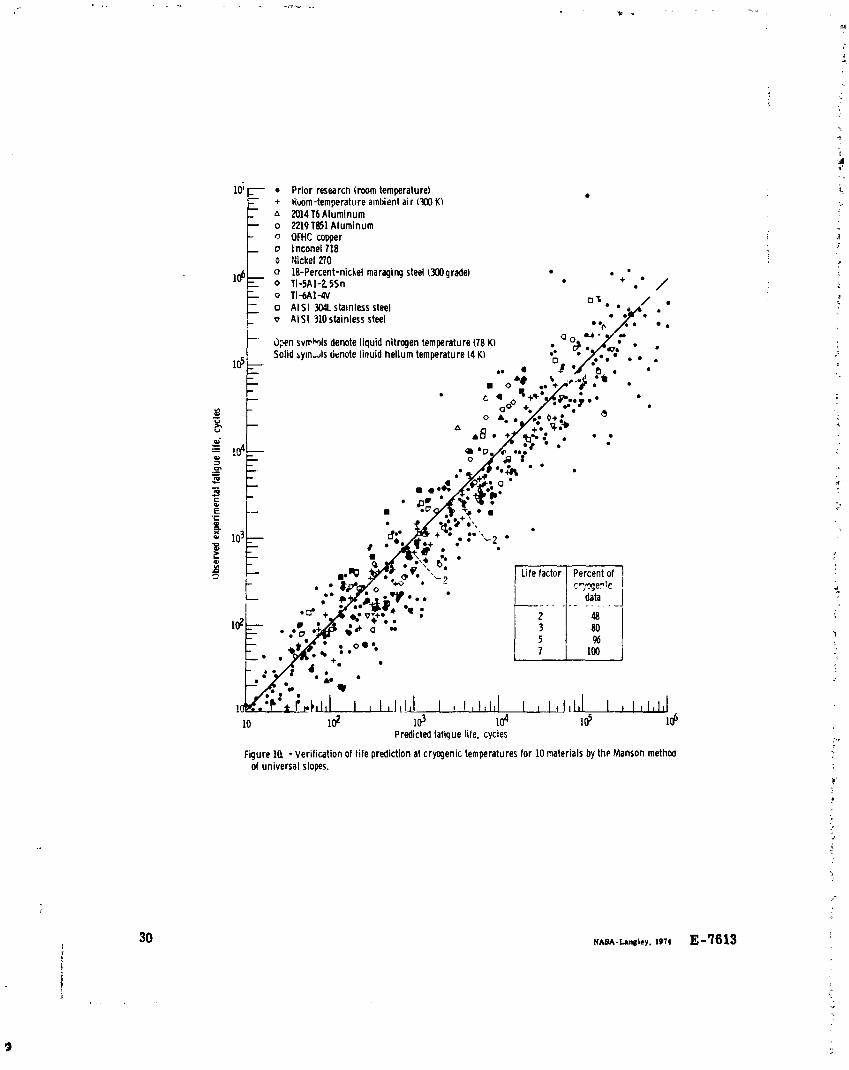
Prior research (room temperature) Kwm-temperature ambient a i r (3&l UKI 2014T6 Aluminum 2219 1851 Aluminum OFHC copper I nconel718 :kke l 270 18-Percent-nickel maraging steel W l g r a d e l . * Ti-5A1-2 5Sn .
+ .* / Ti -6A1-4V Al S l 3U4l stamless steel A l S l 310stainless steel .
3 p n svr rb ls denote l iquid nitrogen temperature (78 KI Solid s y m ~ l s denote l inuid hel ium temperature (4 K)
10 I$ lo3 18 ld 1 4 I
Predicted fatique life. cycles
Figure la -Verif ication of l i fe prediction at c ryqen ic temperatures for 10 materials by t h ~ Manson method of universal slopes.