national advisory!,;:gommittee’,,,,- for …/67531/metadc64484/m2/1/high... · acceleration...
TRANSCRIPT

—.-
...-
.. -. -.
,-
,Deutsche
NATIONAL ADVISORY ;:GOMMITTEE!, ’,,,,-FOR AERON~:@&~$Sr
$,,,.,.,-,,,,,
‘,..-:.~,
,., .’.,.
,,, ::“’.’,. .,-,
.,!’
COMPARK$ON OF DROP AND lKDl_D-TUNNEL EXPERIME~S ON,.
BOMB DRAG AT HIGH SUBSONIC SPEEDS; .:,-,,....-... ...... . . ..._=....
BY B. Gdthert
.....:‘ ,.”-. .. —— .. . ........ .. ... . . .... .-, .,,,, ’.-;,:$. ‘ @@,,&&@#@ *.$ .~> .~-$~d~ -‘- kxzz%.-:.. . . .., >k,::j ..-2’$:‘.: . . .
,: ‘~j$?l%~-. _ TRANSLATION -,,.
*‘.._:y#,i ., ._,. , ,, ...’..., , .,., ,, .~~.:~’~w: ,i +.j.,:-.’”%%F’, “ ;J” ;:
UVergleich zwi&?&en&4~b’wurf- und Windkanalversuchen hinsichtlich desWiderstandes vonB*omben bei hohen Unterschallgeschwtidigkeiten”
,..
.
Luftfahrtf orschung, Forschungsbericht,,-.Nr. 1570
,,.
Washqin@Ok-=y==w=--=--=-=
May 1948.
.

*<* -v.- * u.”;
NATIONAL ADVISORY COMMITTEE FOR AERONAU121CS
TECHNICALMf!MORAN’UMNO. 1186
,-... . “~i - -.-....—
COMPARISON OF DROP ti’ WIN&TUNNEL EXI?ERIMEN’1%
BOMB DRAG AT HIGH SUBSONIC SPEElX#3‘,
Qy B. .G6thert
SUMMKRY
The drag coefficients of bombs at high velocitiesvelocity of fall was 97 percent of the speed of sound)
ON
(the highestare determined
by drop tests and compared with measurements taken in the DVL hi~h-speed closed wind tunnel and the open jet at AVA - G&btingen.
1. PURPOSE OF THE DROP EXPERIMENTS
1. Limits of Mensurability in Subsonic ~.indTunnels
The upper limit of the a$rsFeed in subsonic wind tunnels atwhich it is no longer possible to carry over wind-tunnel measurementsto free flfght is that velocity at which the supersonic fieldoriginating in the flow past the model has spread out to the flowboundary. It is not known how closely this upper limit can beapproached, that is, by what amount the airsyeed must remain smallerthan the limlting velocitp. In the closed D’VLwind tunnel.,thevariation of preesure on the wall and the v@ocity variation alongthe test length are measured along with all model measurements takenat high airspeeds so that it can be established each time leyondquestion when the speed of eounfi,and, therefore, the lmge~t pos~i,ble
*“Vergleich zwischen A~wurf- und Windkanalverauchen hinsj.chtlichd.eslJider@xandesvon Bomben bei hohen Unterschall~eschwlndi~keiten.”Zentrale fi.irwissenschaftliches Berichtswesen der”Luftfahrt~orsch~gdee Generalluftzeugmeisters (ZWB) Eerlln-Ad3ershof,ForschungsberlchtNr. 15’70,April 17, 1942.
lThe DVL would like to take this opportunity to thank the varigusestablishments, the Rheinmetal.1-BorsegF5.rmand the LuftwaffeExperimental Station at 32eeneti’nde- Vest especially, for theirsupport in substantially expediting the drop expe~”iments.
.. — . .

I-=
II’ k”*
2 NAC!ATM NO. 1186
airspeed are attatned.. l?orpurposes of evaluation, measurements inthe proximity of the upper velocity limit are discarded from time totime. No equiva3,entsign for the limiting velocity that can bereached in wind tunnels with open test lengths is known.
Since there is no -prospectfor acceptable measurement in windtunnels in the immediate vicinity of the,speed of sound, it isnecessary to extrapolate in this remge from measurements made atlower velocities, However, this requires high reliability ofmeasurement, especially in the critical velocity region,that is,inthe vicinity of the limiting airspeed, since, aside from the magni-tude of the individual measurements, the slope of the experimentalC1.aiWeiS important, tOO,
. ‘“,,
2. Correction Factor for the Flow Velocity in Subsonic l?u~els
Wind-tunnel experiments hs,veshown that the air drag of themodels tested rises considerably if the airspeed is Increased to
the neighborhood of the speed of sound. Tillsdrag blse of the models,according to known measurements in wiu.dtunnel~, has,been larger,in general,’with clo~ed test lengths than in open arrangements. ‘l’hisdifference is understandable, too, as long as no velocity correctionfactois’are used as a result of the model obstructing the test length,As a result “of the obstruction of the test length, the air in a closedtunnelnust flow past ‘themodel with a higher velocity than in an.empty test’lAngth, which produces higher drag and with this, too.,,larger drag coefficients are simulated at velocities that are.too.low. Conversely, the air in em open jet canbe deflected more .easilythanin the unbounded air space so that the effective flow velocitybecomes “smallerand the drag and drag coefficients appear too small.
In the operation of the DVL high-speed wind tunnel a correctionfactor method was discovered whiah yermits the calculation of thevelocity correction factor for closed wind tunnels at high airspeeds,too, in a simple manner with ~he help of the dynemic pressure at thewall measured simultaneously. Since this semiempi.ricalcorrectionfactor method can not be taken over for an oyen wind tunnel withoutfurther development and, at present, no other metinodhas been workedout yet, a velocity correction factor has bean omitted, up to now,, -,for the open arrangement. This omission of the velocity correctionfactor in open Jet experiments, for which only a smaller correctionis known to be necessa.qythan for a closed wind tunnel with the sameobstruction of the test length, is justified as long as the dimensionsof the model which uust be tested near the syeed of sound are chosensmall enough. However, there is no accurate knowledge of what are tobe considered sufficiently small.dimensions of the model.
———‘Compare B. (lothert: “Windkanalkorr6ktmen bei hohen Unterschall-
geschwindigkeiten,”IG&Tagmg~bericht 127, p. 113.

NACATM No. 1186 3
.
3. Checkhg the Wind-Tu~elResults By Drop:Tests ;Ta--,..-. ,,4 .. . ............ ,..” ..—.——— .,. ..-.,.-. .
Although valuable evtdence concerning the magnitude of theinfluence of the”sti’eamboundaryandthe li~ting airspeed isacquired by systematic witi-tunnel exoeriments~,’for ex~ple withlarge and with %ry ’smallmodels of the same form in the.seinetunnel,there exists the pressing necessity of atleast knowing ‘thevariation
‘, of the aerodynamic forces for several bodies in un3Nnited airspaceand thereby ~ossessing,a means of examining the reliability of.thewind-tunnel method ‘ofmeasurement..... . . .
In the present report we will deal with an attempt to determinethe drag variation of bonibsat high subsonic speeds by drop testsof original bombs from an airplane. Bom?x3were selected as testbodies because there were sufficient numbers of them and the supportsand release installationswere available in guantity$ also. Accordingto holifavorably these f~.rsttests run off, these tests will beextended to other bodies such as rectangular wings, sweptback wings,and so forth. Among other things, several fallinR bodies axe to beselected with the correct weight and dro_ppedfrom the right altitudeto exceed the speed of sound in order to obtain evidence in the samerange covered in wind-tunnel experiment~.
II. PERJ?OHMANCEOF
The drop tests were carried out
DROP EXPERIMENTS
by,D~ with the support ofthe Rheinmetall-Borseg firm. The measurement of the tra.~ectorvwasmade by the measuring-squad’of the Luftwaffe research establishmentat Peenemiinde.
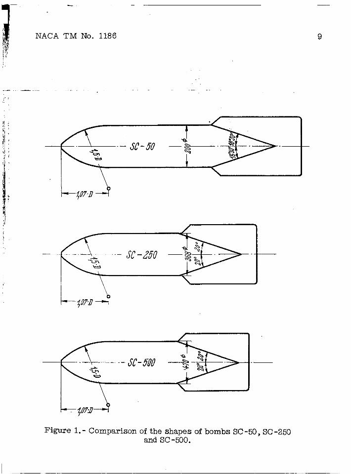
Several original bomb’sSC-50”and SC-2>0 with and without tailfin struts (fig. 1),weie”released apd observed. The bombs wereequipped with flm-es (flare dimensions 190 X 60 millimeters di~e~er)which were installed on the bomb axis behind the corresponding cut outof the %omb tail in ,theS0-50 bombs, somewhat off center in the anglebetween two fins in ‘th6.SG-250 bombs.
‘B. G?$thert: “HochgeschY~indigl<eits-Untersuchungenan symmetrischenl%?ofilenmit verschi.edenenDickenvarh31tnissen im DV&Hochgeschwind-igkeits-Windkanal (2.7 m ~) und Tergleich tit llessu.ngenin An.derenWtndkar&len,” Forschungsbericht Nr. 1506,p. 17.G. Richter: “Einfluss der Mcdell@%8se in Hochgeschwindigkeitskatialen(Messungen an vier verschieden giossen F1igeln von gleichem ProfilimDVL-Hochgeschwindigkeit%-Wind&nal) ,“ LGkTagungsbericht 127, p. 121.
..—------ _-. -—.-——..—.

NACA TM No.1186
The bombs were dropped from a height of approximatelyl-lkilometers and their trajectories recorded with two photothe-odolites set up on the ground. From time to time after drops aballoon ristng from the,ground was ob~erved to deterrn3,newindintensity and direction. With these measurements the true velocity”relative to the air was determined. To continue, during the ascentand descent of the airplane fromwhich the labs were dropped,.theair temperature was measured at various heights with en electricthermometer calibrated prior to the experiment to deteaine the airdensity and the speed of somd. A median curve was drawn through theex~erimental temperature points; the experimental points are scatteredwithin 2°0r 3° C of the curve. The uncertainty, due to this, inthe detenuinatiQn of syeed of sound, therefore, is in the orderof 1/2 percent. ,,
The choice of the altitude of?release oi’11 kilometers isbased on argyments which are explained in detail in the followingsection III.
111. INTERPRETATION OF EXPERIMENTAL RMXILTS
The”evaluation of the phototheodolite measurements gives, asraw data, the position of the bomb at intervals of 1/4 or 1/2 second.At eve~ instant, the path which the bomb GoVei”edin 1/2 second wascalculated by means of’the detximoinationof position previously made.This path for each 1/2 second shows the bomb velocity (measured inmeters pe~ 1/2 sefi)which was plotted against the time elapsed andaveraged by a suitable curve,’ The ”&zperimentalvalues for acceptablemeasurements of the velocitT lie within 2 or 3 meters per 1/2 second ofthe average curve.
By graphical differentiation of the velocity-time curve, theacceleration b~B/at acting on the bomb and from that,the air drag
was ascertainedfrom the followin~ equation.
Where
VB path velocity of the bomb
v’s velocity com~onent in the direction of gravity

.—
NACA TM No. 11861 5
c? gxavity . .
.G .-bombweight -.
F(1,
bomb cross-sectional area ‘tD2. ,.. .
P~ air density ,.
It is seen’from this equation, that the.determirlationof dragis more inaccurate, the,la~ge~ the acce~eratiol~of tilebomb .?3VB@t
d~Brelative -to,gravity. For exsmple, if ~ =9.0 meters per second2
and (vSfiB)g = 9.5 meters per seconds2, then the va?.uegoverting the
drag is the difference 9.5-9.0 = 0.5 meters pei+second2, Smal~errors in the determination of the acceleration bVB/&t appear manytimes larger inthe determination of dra~ in this caae. The rangeof high accuracy of measurement ~ossiblly,therefore, depends”on thevelocities which equal the terminal velocity of the bomb or fall freeOf acceleration. To exbencl’thisfavorable range over the largestpossible portion of the drop curve,the bombs were released at thealtitude of 11 kilometers previously mentioned, so that the bombs
reached their highest velocity at an altitude”of k 01: ~ kilometersand then were decelerated, iwtead of accelerated, on falling throughthe lower altitudes as a result of the increasing air density.
Corresponding to the difli’erentorders of accu~acy of measurement,the following three ranges of measurement are differentiated in thedescription of the results and are made reco~nizable on the graphsby individual point designations: ,..
1. Range of small accuracy of measurement.- The acceleration ofthe bomb is even larger than the a~rarily fixed limiting value of5.0 meters per second2, that it is at the highest elevation of thedrop. Not more than a fe~fpoints were evaluated,trom time to:timein this range, when a good”S-traightvariation of the’measurernentspemitted this.
2. Range of increasing Mach number4---The bomb accele~tion herei.s al~~ady smaller -than S.O meters persecond2 and falls”off toam— = o, ~ossibly.at This range terminates where’the bomb’attairisits
closest approach to the speed of”sotid’in the vicinity of the limitingvelocity. . . .
3. Range of decreasing Mach number.--Zn this rage the bomb—— _—-—___acceleration is almost always negativ~~ that is, the bombs are retarded
% = The ratio of pathvelocity/velocity of sound
.— —

6 NACA TM No. 1186
as a result of the drag so that the highest accuracy of measurementis obtained in this range. This range ends on impact with the ground,
Good control of the results is obtained, therefore, due to thefact that each drop is made from a high enough altitude so that therange of high Mach numbers is traversed first wtth increasin~ andthen with decreasing Mach number, Thereby, two different, mutual~independent parts of a curve are obtained which must fit together.
In the manner described, for each drop only that portion of thedrag curve is obtained which is well placed, that is, located inthe vicinity of the limiting Mach number. If the drag curve for alarger Mach number range should be determined, the limiting Machnumber would have to he shifted according~~. This could be accom-plished ly dropping more models o,fdifferent weights but the sameexternal form. Corresponding experiments on bombs, which are partlyunloaded, partly more or less heavily loaded with weighty materialsare in preparation.
The accuracy of evaluation can be increased further, if, insteadof the graphical method employed here, that is graphic differen-tiation of the average curve drawn through the experimental values,an ‘averageis determined by mathematical averaging calculations andthen differentiated. However, it is not to be expected that aconsiderable improvement will be obtained in the range of high Mach
numbers. The advantage of these refined methods of evaluation isseen principally in the range which is termed “The range of smallaccuracy of’measurement” in the foregoing.
IV. RESULT OFDROl? TESTS AND COMPARISONtiTEWlND-
Theshown as
TUNNEL WU13U4ENTS
drag coefficients Cw obtained by the drop tests arefunctions of the Mach numker in figures 2 and 3. The drap
tests made are shown as follows:
2SC-50bombs. . . . . . . . . , . , . . ~0 . , . . . . Infigure2
1 SC-250 bomb without tail fin strutsfoicomparison. . . . . . . . . . . . . ● Oo1nfi~res2and 3
1 SC-250 bomb with tail fin struts . , , . , . . . . . . In fi~re 3
The SC+O bomb used in carrying out the experiment,has no tailfin struts. The original SC-250 bomb had tail fin struts as
,..

;’
.-,
‘,
. . .
,.
NACA.TM,NO. 1186 7
standard equipment ~n order to stiffen the tail surfaces..:The tall— fin s@uts have a .diameter.of..l6milli@$e,~@ for.,abomb.diameter of
368 millimeters.
The closest approach to the velocity of sound was made by theSG250 bomb without tail fin wtruts wi.tha velocity 97 percent of thespeed.of sound, ‘Alloft,he dnag.curves o%tained from the drop tests“showa very steep increaee of drag on,approaching the speed ofsound. This agrees very well with the experimental curves from the’closed DVL high-speed.wind tunnel which are,drawn in for comparison.Admittedly, the wind-tunneland drop-test curves are displaced.“byadefinite ~ount of dzzagfrom one another; however, the increase ofdrag on approaching the speed .of,sound .showsvery good agreement;the increase ,ofdrag, incidentally, was observed especially“clearlyin this experiment.
The measurements from the DKL high-speed wind tunnel, citedfor comparison,,[email protected] carried out for a model of the &q-2>0 bombwhich had a diameter of’123 m!.llimeters. TWO fuse+openings and.asuspension lug for horizontal mounting of the bomb were added.to themodel. The variation of drag for the SG>O born%!naGnot been measuredin the wind tunnel as yet. Tlfie.meaaurernentsare now being preparedfor.5 However, as a result of ‘the~reat similarity between the SC-50and SC-250 bonlls(compare fig. 1), It is to be expected that the dragcurves for the.two bombs would.differ from one another by only a smallamount.
In f-igure.4the variation of drag of the tombs investigated inthe closed DVL h~gh--speedwind ‘tunnelhas been compared with that ofthe open jet, AVA - Giittinge1106 The experimental curves have beenextrapolated somewhat beyond the measured range to larger Mchnumbers in.conformity with the slope at the end of the curve. Theexperimental curves for the same tombu could not always be used forpurposes of comparison of bomb drag in these illustrations. However,sinc~ the bomb shapes are extraordinarily alike (compare fig. 1.),forexample, the SC-250 and S0.-500bombs without tail fin struts have
. .,
%Phe report.on the”v~d-tunnel measurements for all.bombs will bepublished as ’,soonas the measurements on’the model of-the “S&50 bombhave been completed,
6A. Roth: “Untersuchungenvon Bomben im komvressiblenlJnterschallgebiet”~AVA-Bericht 41./8/8, September 1941. ~ ,,..
On the basis of more recent calibrations of the wind tunnel atGottingen, the experimental results pre~ented in the AVA report hadbeen corrected before they were cited for the comparison in figure 4.This conversion is In the direction to reduce the differences betweenthe DTL and the AVA measurements.
I —

8 NACA TMNo. 1186
practically the same shape:with one another and be usedmind.
The reproduction of’ thedrop tests ha~ not been mademeasurements agree well withspeed wind tunnel~ (Compare
The curve~, therefore, can be comparedsatisfactorily for the comparison in
experimental curves obtained in thein figure 4 because the drop+testthe measurements of the closed DVL high-fig~, 2 and ~.)
The conrparisonof the curves shows that the measurements in theopen jet do not exhibit the sharp drag increase like those of theclosed DVL wind tunnel and, therefore, are also unlike the droptests. The cause of the deviation may be looked for in the fact thatno velocity correction factors were ayplied in the open-jet measure-ments to take care of the effects of the obstruction of the testlength by the model, or that the 13eynold~number in the open-jetmeasurements were extraordinarily low as a result of the limited wind-turirieldimensions (the bomb model dismeter was 25 millimeters in theAVAmeasuremen-ks!).
v. SUMIW.RY
1. “Droptests were made by dropping original bombs from a highaltitude and by taking measurements along the drop curve. The largestvelocity of fall in these experiments cuuoumtedto 97 percent of thespeed of sound.
2. The variation of the drag coefficients for bombs obtainedfrom the drop tests agreed closely with the measuiwuents in theclosed high-speed wind tunnel of DVL. In particular, according todrop and wind--tunnelmeasurements there is an extraordinarilysteep &rag increase when the velocity of fall a~yroaches the velocityof sound.
3. A comparison of drop measurements with drag measurementsof,the same boubs in the open jet of AVA .-G6ttingen shows that theincrease of drag is undervalued on approaching the speed of soundin the open-jet measurements.
Translated by Dave $’eingoldNational Advisol~ Comnitteefor Aeronautics
—
NACA TM No. 1186
--- ..— . ..-
,-,
9
t
‘– JC-3U—’&--i
/
L$om--!
—.!
\
Figure 1.- Comparison of the shapesand SC -500.
SC.-5O , SC-250
I

10
INACA TM No. 1186
Figure 2.- Comparison of the drag coefficientsobtained from- Wind tunnel and release experiments for SC-bombs without
tail fin struts for various Mach numbers.
Drag coefficientv?
Cw =P/2v%?
Bomb frontal area F=:D2
Mach numberM = Trajectory speed
Sonic speed

—-
N.ACA TM No. 1186
—
-- ...
::0
*:
:
e*
:.
1
—
—
—
—
—.
—
—
—
11
Figure 3.- Comparison of the drag coefficients obtained fromwind tunnel and releasewith and without tail fin
Drag coefficient
Bomb frontal area
Mach number
IL—-.
experiments for the bomb SC-250struts for various Mach numbers. ,
w‘w =
P/2V2F
F= ~ D2
M = Traj eCtOry speedSonic speed

———. ———.— -----. .
NACA TM No. 118612
L$
44
(p’
C)y
i /SC-bombs withouttall~imstruts :
f’j~~-[C1OE8Q~lnd t.... I j
SC-/j’5Owithout tail fin struts ; ,,.,
/’A
-_ /4yA- OP@Jn j.t
JC-50\ ,/ ‘
/ ‘
Extrapolated o“rves .--------
N = velocity of trf4jeat0ry/.0nic velocity:
I I I I I I, 1 1 1?
I44 &f L& 47 48 6
Cwl I bomb SC-250 without and with tail fin struts II
-9 5
T,’
,’/’
/’
with tail fin strutsExtrapolated CUFfe S . . . . . . . .
— i .
~~ - closed wind tunnel
$t-500withOut tail
fin struts~
Without tail fin struts
M = Ye locity of trajectory sonic velocity
6?4 45 (M (V Q$ 49 (
q4
o[Figure 4.- Comparison of bomb drag coefficients from measurements
in the closed DVL wind tunnel and the open jet, AVA -Gottingen.
.,

“ “,7. , ..:, ..,7.. .-.:-----.,,. . ,2- ““’”. ,. ,,,
+. . . ., –.
,“’-. .
, %, ‘G” “ iillllllmomlmll1‘~~%3fEk&:. ... :‘-.”‘“h“.‘5%!E5L;;.:’‘ .’.Q$$M2&m‘:““:3117600516.,,,””c-..+*Y,,,,;.,,.,./---- .4
.,,,.
f. .+
‘. ,,
●
,.,.. .. ....
,,