national central university department of electrical engineering dsp lab. introduction of ip...
TRANSCRIPT

National Central UniversityDepartment of Electrical EngineeringDSP Lab.
Introduction of IP Generator
Speaker : Peng Chen Chi

National Central UniversityDepartment of Electrical EngineeringDSP Lab.
OUTLINE
IntroductionBehavioral Level IPADD/SUB IP GeneratorViterbi Decoder IP BuilderReed-Solomon Code GeneratorFFT IP GeneratorConclusion
National Central UniversityDepartment of Electrical EngineeringDSP Lab.
Introduction
What is IP ? Intellectual Property
(IP):Intellectual property means products, technology, software, etc.that have been protected through patents, copyright, or trade secrets.

National Central UniversityDepartment of Electrical EngineeringDSP Lab.
Introduction(cont.)
The electronic industry is moving toward the design and implementation of entire systems on a single chip (SoC).
Three types of reusable core (IP Core) can be distinguishedThe Soft Core is described using a high level description language (i.e. VHDL or Verilog),The Firm Core is described and synthesized for specific library and finallyThe Hard Core is described at the layout level.

National Central UniversityDepartment of Electrical EngineeringDSP Lab.
Behavioral Level IP
We can define a set of objective criteria for a Behavioral- Level IP (BL-IP) that guarantees the performances of the block:
Blocks models must be uniform. This enables the extraction of generic parameters and rules to define and compare different implementations of functions.BL-IP overhead development cost must be reasonable. Flexibility is an important characteristic for BL-IP. The environmental adaptation of BL-IP is done by setting a set of parametersBL-IP performance have to be tool independent. This
criterion introduces the concept of Universal High- Level-Synthesis (U-HLS) tool. To reach these goals, we propose to use an interface called a
generator and to specify the IP at the behavioral level associated to the use of a methodology to simplify the IP integrator task.

National Central UniversityDepartment of Electrical EngineeringDSP Lab.
Definition of IP Parameters IP parameters have three different levels
of abstraction:Algorithm selection parametersIntegrator parameters and constraints.Synthesis tool parameters.
Parameters can interact with another from a different level, and can be defined by enumerations or bounds.

National Central UniversityDepartment of Electrical EngineeringDSP Lab.
IP Generator General Architecture
The interface enables the specification of constraints and parameters for a particular block, that will help the integrator in the definition of the IP.The estimator guides the designer to a good implementation of the function according to the required performances.The U-HLS generator takes the parameters defined through the interface and generates an U-HLS IP.Derivators transform an U-HLS IP to a tool specific description of the BL-IP.

National Central UniversityDepartment of Electrical EngineeringDSP Lab.
Parameterized IP Design
Why to parameteriz IP? Provide flexibility in interface and functionality Facilitate verification
Parameterizable types Logic/Algorithm functionality
DCT,IDCT,DST,IDST Structural functionality
Bit-width,depth of FIFO,etc Design Process functionality
Test events Event reports Automatic check event

National Central UniversityDepartment of Electrical EngineeringDSP Lab.
ADD/SUB IP Generator
Input parameterTypes of ADD/SUB
Ripple adder (RA) Carry-lookahead adder (CLA) Carry-select adder (CSA) Carry-bypass adder (CBA)
Types of functionality Addition Subtraction Addition/subtraction

National Central UniversityDepartment of Electrical EngineeringDSP Lab.
ADD/SUB IP Generator
Input parametersword lengthAdd register on (input/output/none)Performance optimization
Area or timing
Fixed stage sizing on architectureFixed stage size for CLA, CSA, and CBA4-bit is suggested as stage size

National Central UniversityDepartment of Electrical EngineeringDSP Lab.
ADD/SUB IP Generator
Outputs IP builder GUI Synthesizable RTL code Synthesis scripts
To apply the files ,can be immediately reported to the user the results of timing,area and power.
Test benchesAutomatic output checking and error
reporting

National Central UniversityDepartment of Electrical EngineeringDSP Lab.
ADD/SUB IP Generator
Documentation The documentation part resumes all
the information about the IP generator .This documentation must contain the function description , a set of performances and characteristics and the interface
description.

National Central UniversityDepartment of Electrical EngineeringDSP Lab.
Viterbi Decoder IP Builder
National Central UniversityDepartment of Electrical EngineeringDSP Lab.
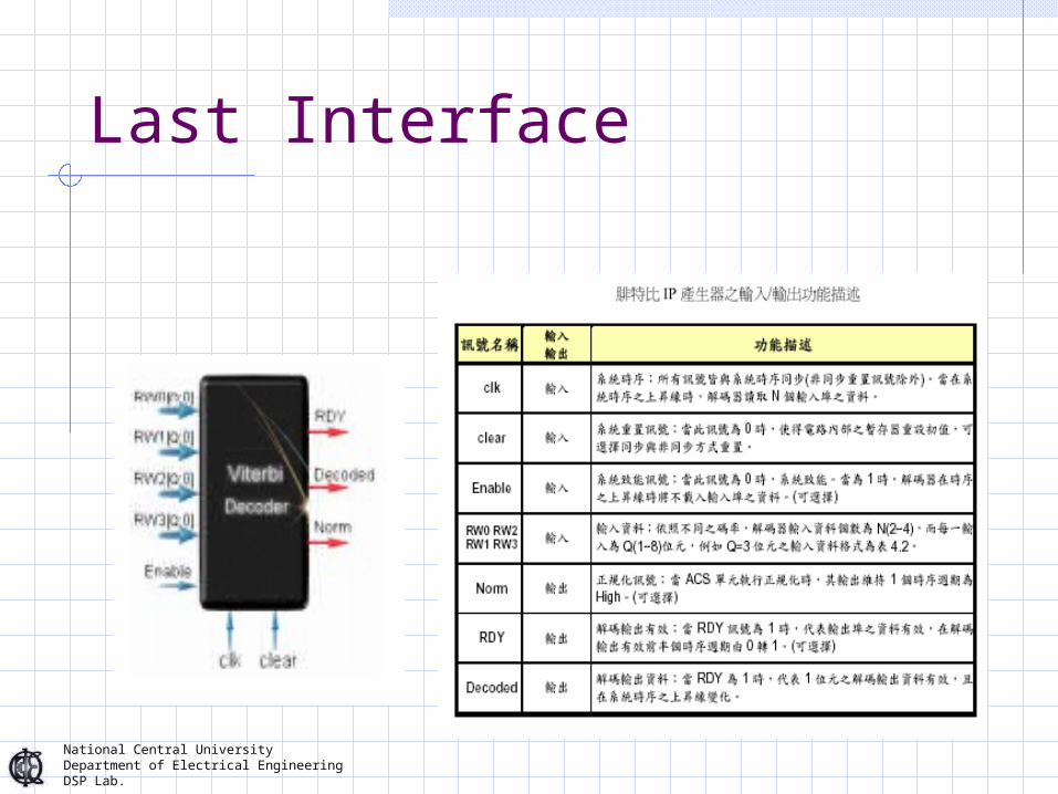
Last Interface

National Central UniversityDepartment of Electrical EngineeringDSP Lab.

National Central UniversityDepartment of Electrical EngineeringDSP Lab.
National Central UniversityDepartment of Electrical EngineeringDSP Lab.

National Central UniversityDepartment of Electrical EngineeringDSP Lab.
Source RS
encoder
Channel
RS
decoderSource
Noise
Reed-Solomon code

National Central UniversityDepartment of Electrical EngineeringDSP Lab.
Reed-Solomon code word
………
…………
n symbols ( m-bit)
2t redundancy symbols
k information symbols

National Central UniversityDepartment of Electrical EngineeringDSP Lab.
Reed-Solomon Code Generator
The RS Code Generator consists of three parts
Design Parameter Manager
Module Integration Arrangement
Automated Synthesis Interface
Design parameter Manager
Design Spec.
Module Integration Arrangement
HDL Output
Automated Synthesis Interface
Modules Synthesis Report
(Gate count, Speed , Power , memoty size)

National Central UniversityDepartment of Electrical EngineeringDSP Lab.
Parameters of RS code Generator
Basic Parameters Symbol Width (m)
We often use m=8 for one symbol width, we also define m=4 ,and m=7
Capability of Error Correction (t)The user can choose how many symbol can be
corrected. Block Length (n)
The user can decide the length of a code word. But the maximum length is limited by symbol width (m)
Information Data (k)This parameter indicates the number of
information symbols within a block
National Central UniversityDepartment of Electrical EngineeringDSP Lab.
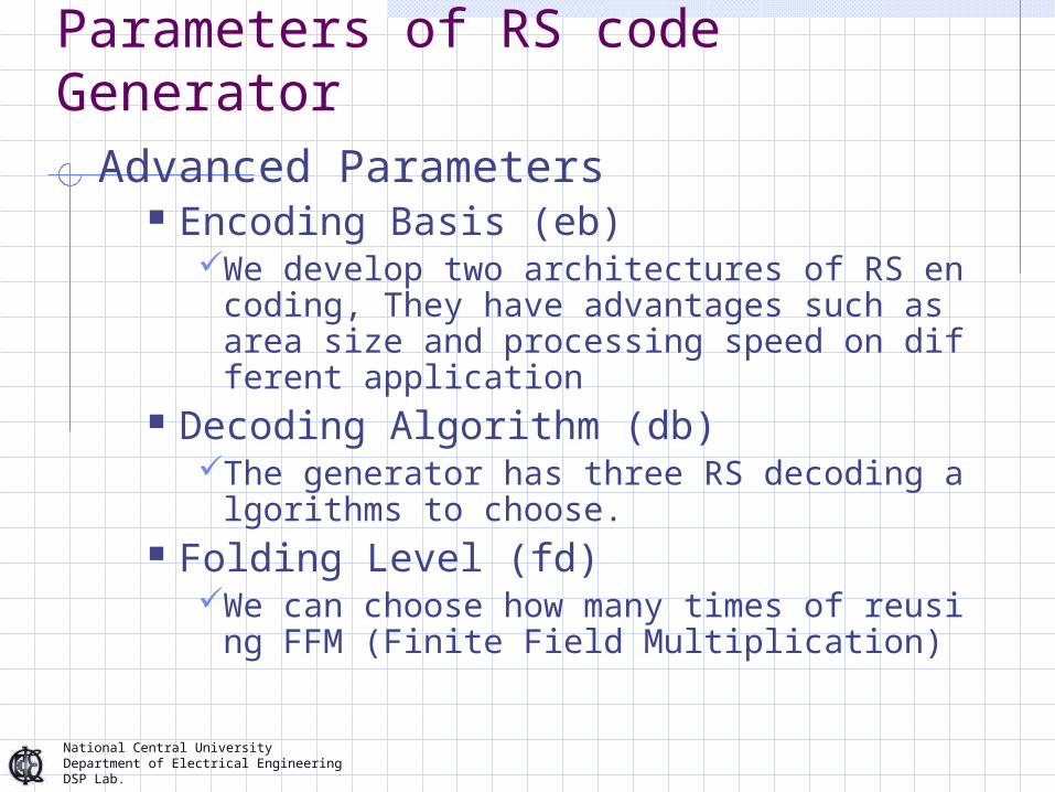
Parameters of RS code GeneratorAdvanced Parameters
Encoding Basis (eb)We develop two architectures of RS encodin
g, They have advantages such as area size and processing speed on different application
Decoding Algorithm (db)The generator has three RS decoding algorit
hms to choose. Folding Level (fd)
We can choose how many times of reusing FFM (Finite Field Multiplication)

National Central UniversityDepartment of Electrical EngineeringDSP Lab.
Operation diagram of RS code generator
Input RS code symbol size m (m={4,7,8}) :8
Input RS code block length n ( n<2^8) :255
Input RS code correctable symbol t (t={2,8,10}) :10
==================================================================
Type 1:g(x) Base. It generates only encoder hardware.
Type 2:a(x) Base. It combines with encoder and syndrome module.
Input Encode code Type(1 or 2) : 1
==================================================================
(1)Don’t do anything
(2)Unfolding by 2 factor -This will increase area
(3)Folding by 2 factor -This will increase speed
(4)Folding by 4 factor -This will increase speed
Input Folding level (1,2,3,4):1
==================================================================
(1) Berlekamp-massy Algorithm
(2) Euclidean’s Algorithm
(3) PGZ Algorithm (only for t<3)
Input RS decoder Algorithm(1,2,or 3) :1
National Central UniversityDepartment of Electrical EngineeringDSP Lab.
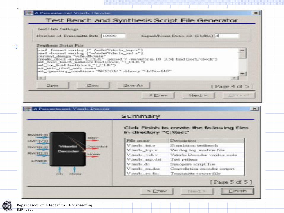
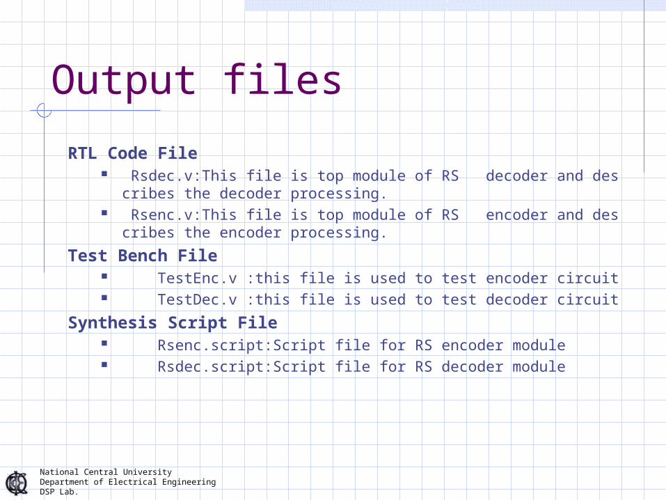
Output files
RTL Code File Rsdec.v:This file is top module of RS decoder and describes the decode
r processing. Rsenc.v:This file is top module of RS encoder and describes the encode
r processing.Test Bench File
TestEnc.v :this file is used to test encoder circuit TestDec.v :this file is used to test decoder circuit
Synthesis Script File Rsenc.script:Script file for RS encoder module Rsdec.script:Script file for RS decoder module

National Central UniversityDepartment of Electrical EngineeringDSP Lab.
FFT IP Generator
利用 Decimation In Frequency FFT的演算法 ,分別搭配 Radix-2,Radix-2/4,Radix-2/4/8 ,Multiple-Path Delay Communicator多管線的硬體架構以 Soft IP的程式結構方式去實現一個 FFT的 IP產生器 .可提供 64~8192點的 FFT Verilog 程式碼 .

National Central UniversityDepartment of Electrical EngineeringDSP Lab.
64Points Radix-2/4/8 FFT signal flow
R-2/8
R-2/4
R2

National Central UniversityDepartment of Electrical EngineeringDSP Lab.

National Central UniversityDepartment of Electrical EngineeringDSP Lab.
FFT IP Generator
輸入 FFT 相關參數 輸入 FFT 相關參數
FFT IP Generator
產生所對應之 Verilog 程式及所對應的 Test bench檔
產生所對應之 Verilog 程式及所對應的 Test bench檔

National Central UniversityDepartment of Electrical EngineeringDSP Lab.
The FFT IP Generator consists of three parts
Design Parameter ManagerModule Integration ArrangementAutomated Synthesis Interface

National Central UniversityDepartment of Electrical EngineeringDSP Lab.
Design Parameter Manager
In our FFT IP Generator, the parameters given by the user are calculated internally to analyse if the parameters are valid.If the input values are invalid, the system will respond error messages to the user.
National Central UniversityDepartment of Electrical EngineeringDSP Lab.
Module Integration Arrangement
Module Integration Arrangement generates a circuit according to the design parameters.Each module is generated by one unit of the design hierachy. This feature makes the module easy to expand and maintain.

National Central UniversityDepartment of Electrical EngineeringDSP Lab.
Automated Synthesis Interface
From the output HDL description, the Automated Synthesis Interface Links verilog-HDL file into synopsys synthesis routines,It is possible to describe the synthesis routine like Verilog-HDL. The files are called dc script files. To apply the files ,can be immediately reported to the user the results of timing,area,and power.

National Central UniversityDepartment of Electrical EngineeringDSP Lab.
通訊系統所需要 FFT 點數對照表
通訊系統 所需 FFT 點數IEEE802.11a 64
IEEE802.11g 64
ADSL 512
VDSL 256,512,1024,2048,4096,8192
DAB 256,512,1024,2048
DVB-T 2048,8192
National Central UniversityDepartment of Electrical EngineeringDSP Lab.
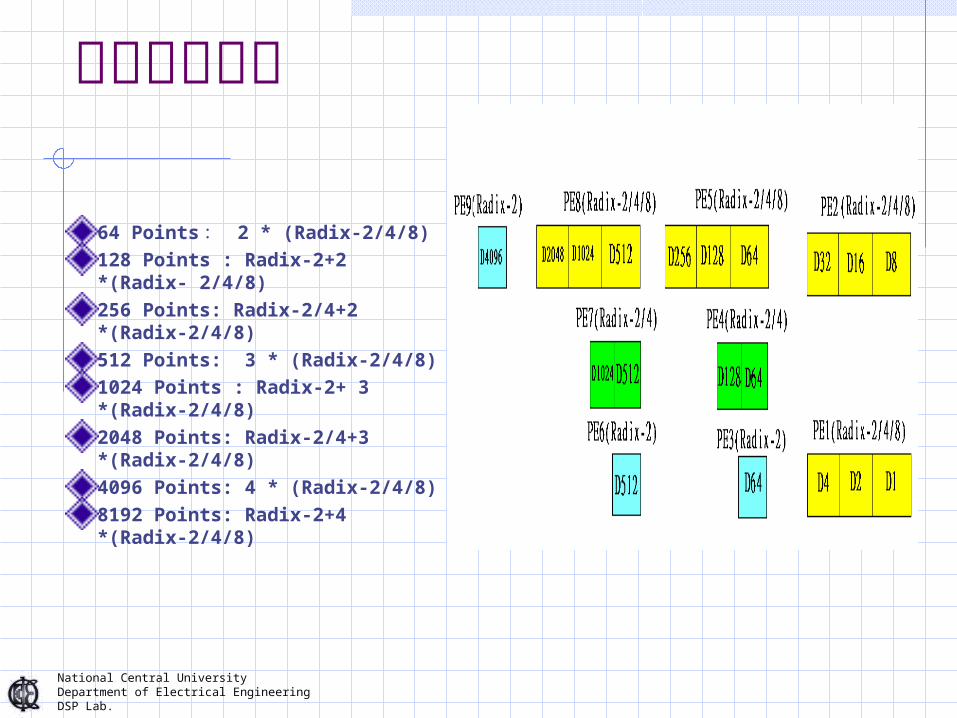
各點所需電路
64 Points : 2 * (Radix-2/4/8)128 Points : Radix-2+2 *(Radix- 2/4/8)256 Points: Radix-2/4+2 *(Radix-2/4/8)512 Points: 3 * (Radix-2/4/8)1024 Points : Radix-2+ 3 *(Radix-2/4/8)2048 Points: Radix-2/4+3 *(Radix-2/4/8)4096 Points: 4 * (Radix-2/4/8)8192 Points: Radix-2+4 *(Radix-2/4/8)

National Central UniversityDepartment of Electrical EngineeringDSP Lab.
FFT IP Generator Block
我們將每一個元件製成一個模組 ,利用物件導向的觀念將所需要使用的元件呼叫進來 ,再把控制電路加進來 ,即可完成一個 64~8192點的 FFT IP Generator

National Central UniversityDepartment of Electrical EngineeringDSP Lab.
FFT IP Generator 所產生之檔案
FFT 之可合成 Verilog 程式碼 FFT_top.v
Test bench :FFT_tst.vTest pattern:FFT_inp.datSynopsys dc script:FFT.dc

National Central UniversityDepartment of Electrical EngineeringDSP Lab.
GOAL
我們的 IP generator 能夠自動的對於不同的參數值產生相對應的 FFT code 此一 IP generator 具有以下特性
1. 提供一簡單之操作介面 , 減少使用者對於參數的設定 錯誤 2. 標準檔案輸出 , 產生可程式化的 Verilog code. 3. 自動產生測試模組及測試向量 , 達到快速驗證之效能 4. 提供一自動合成描述檔 , 能夠迅速的產生閘階層電路 5. 合成結束後 , 提供關於指定參數之面積 , 速度及功率之報告

National Central UniversityDepartment of Electrical EngineeringDSP Lab.
Conclusion IP Generator Inputs
Power dissipation, code size , application performance , die size ,etc
Types,number ,and sizes of functional units, including processor
User defined instruction
Outputs RTL code and testbenches Synthesis and P&R Scripts

National Central UniversityDepartment of Electrical EngineeringDSP Lab.
設計流程介紹

National Central UniversityDepartment of Electrical EngineeringDSP Lab.
Cell based Design Flow