national control point survey work specifications …
TRANSCRIPT


NATIONAL CONTROL POINT SURVEY WORK SPECIFICATIONS
(DRAFT)
DEPARTMENT OF LANDS AND SURVEYS, DEPARTMENT OF STATE FOR LOCAL
GOVERNMENT AND LANDS,
THE REPUBLIC OF THE GAMBIA

CONTENTS
Chapter 1 General .....................................................................................................1
Chapter 2 Work Plan .................................................................................................3
Chapter 3 Selection of Points ..................................................................................4
Chapter 4 Survey Markers........................................................................................7
Chapter 5 Observation..............................................................................................8
Chapter 6 Calculations ...........................................................................................17
Chapter 7 Arrangement ..........................................................................................22
- 1 -
NATIONAL CONTROL POINT SURVEY WORK SPECIFICATIONS
(DRAFT)
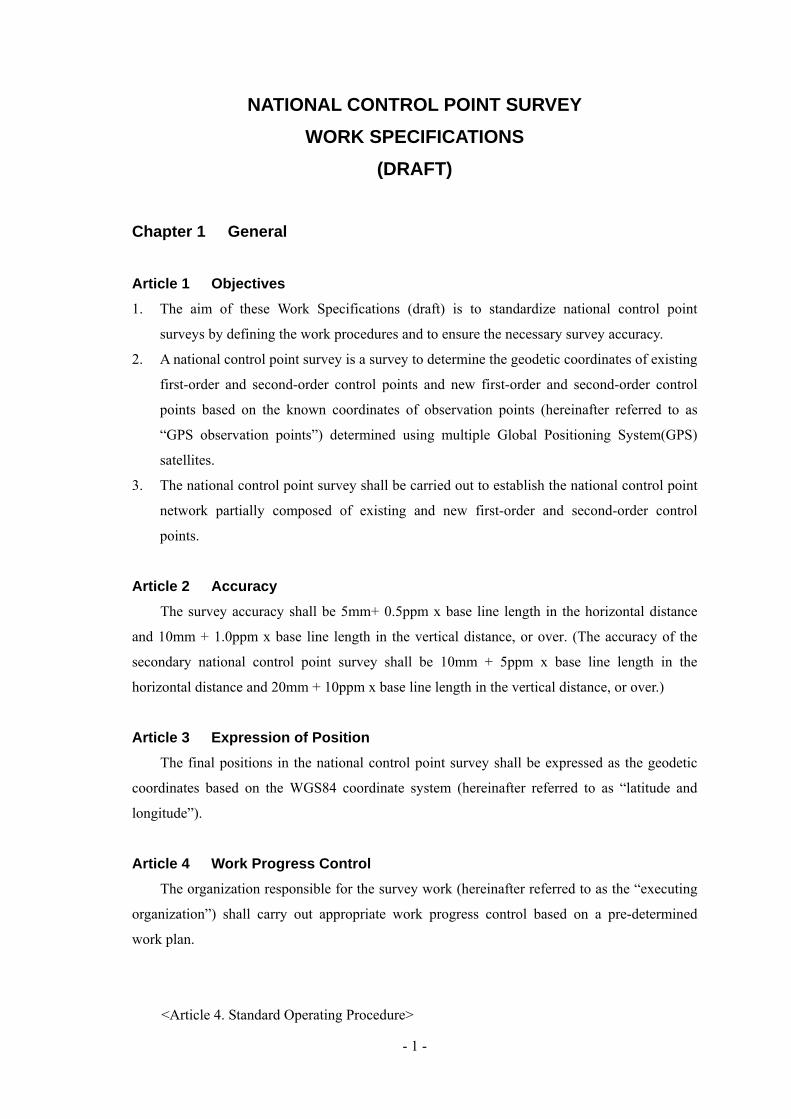
Chapter 1 General Article 1 Objectives 1. The aim of these Work Specifications (draft) is to standardize national control point
surveys by defining the work procedures and to ensure the necessary survey accuracy.
2. A national control point survey is a survey to determine the geodetic coordinates of existing
first-order and second-order control points and new first-order and second-order control
points based on the known coordinates of observation points (hereinafter referred to as
“GPS observation points”) determined using multiple Global Positioning System(GPS)
satellites.
3. The national control point survey shall be carried out to establish the national control point
network partially composed of existing and new first-order and second-order control
points.
Article 2 Accuracy The survey accuracy shall be 5mm+ 0.5ppm x base line length in the horizontal distance
and 10mm + 1.0ppm x base line length in the vertical distance, or over. (The accuracy of the
secondary national control point survey shall be 10mm + 5ppm x base line length in the
horizontal distance and 20mm + 10ppm x base line length in the vertical distance, or over.)
Article 3 Expression of Position The final positions in the national control point survey shall be expressed as the geodetic
coordinates based on the WGS84 coordinate system (hereinafter referred to as “latitude and
longitude”).
Article 4 Work Progress Control The organization responsible for the survey work (hereinafter referred to as the “executing
organization”) shall carry out appropriate work progress control based on a pre-determined
work plan.
<Article 4. Standard Operating Procedure>
- 2 -
1. The executing organization shall report the progress status of the work as deemed
appropriate.
Article 5 Accuracy Control The executing organization shall conduct appropriate accuracy control in order to ensure
the accurateness of the survey.
<Article 5. Standard Operating Procedure>
1. The executing organization shall prepare and submit an accuracy control sheet
based on the result of accuracy control.
- 3 -
Chapter 2 Work Plan
Article 6 Preparations and Planning The executing organization shall formulate an appropriate work plan and make
preparations for the various works before commencing such works.
<Article 6. Standard Operating Procedure>
1. The work plan shall be formulated as follows:
(1) The latest information on GPS satellites shall be collected.
(2) The work period, work formation and work schedule shall be determined
taking into account the latest information on GPS satellites.
2. Work preparations shall be made as follows:
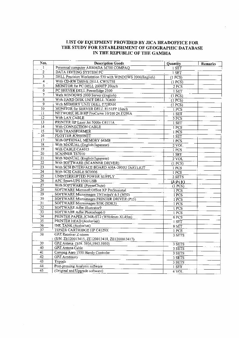
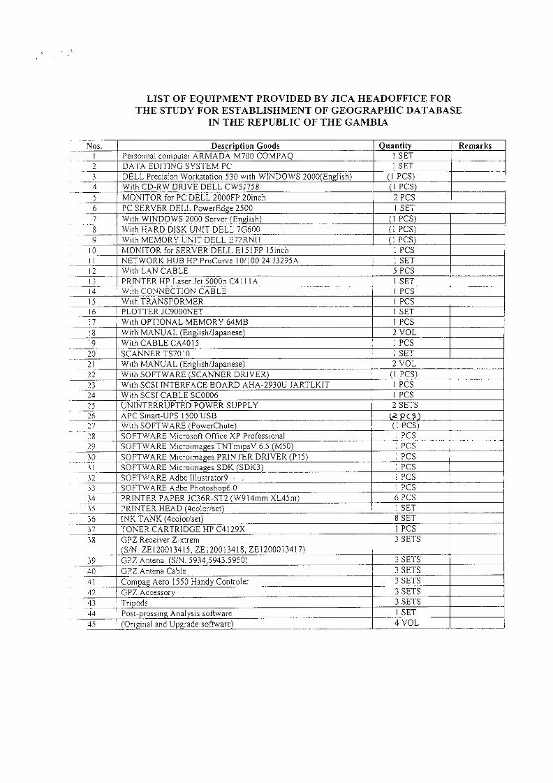
(1) The survey products, equipment and consumables to be used for each work
shall be prepared.
(2) The equipment shall be inspected and maintained and the safety functions of
the equipment shall be checked.
Article 7 Preparation of Net Adjustment Planning Map The executing organization shall check the distribution of the GPS observation points,
existing and new first-order and second-order control points and bench marks (hereinafter
referred to as “control points”) by referring to topographic maps and determine the operating
procedure, and prepare the plans for net adjustment.
<Article 7. Standard Operating Procedure>
1. The net adjustment planning map shall be created as follows:
(1) 1/250,000 and 1/50,000 topographic maps shall be used.
(2) The control points shall be clearly indicated on the topographic map.
2. The network on the net adjustment planning map shall be configured as follows:
(1) In principle, the network shall be composed of a number of unit polygons.
(2) A single unit polygon shall consist of one GPS observation point and three
(3) or more control points. The unit polygon shall be measured
simultaneously using GPS receivers.
3. The control points that are located within a distance of 5km from the benchmarks
shall be connected to the benchmarks by leveling.
- 4 -
Chapter 3 Selection of Points
Article 8 Investigation of Actual Conditions 1. The actual conditions of the GPS observation points and control points shall be
investigated referring to the net adjustment planning map .
2. Appropriate measures shall be taken for those of the existing controls points where
an abnormal situation is found as a result of the investigation of actual conditions.
<Article 8. Standard Operating Procedure>
1. The actual conditions of the GPS observation points and control points that have
been investigated shall be photographed.
2. The investigation of the actual conditions of existing control points shall be
carried out as follows:
(1) The loss, inclination, excessive exposure or burial, and damage of existing
control points shall be verified.
3. The following measures shall be taken for those existing control points where an
abnormal situation is found:
(1) For the control points that are deemed to be abnormal, their robustness shall
be checked and then they shall be treated as new stations.
(2) If any existing control points are lost, a monument shall be set at a new
point.
4. New control points shall be monumented in accordance with the specifications.
Article 9 Determination of Work Procedures 1. The conditions at the site, such as the terrain, vegetation, any radio obstructions
and other features, shall be investigated based on the net adjustment planning
map to determine the optimum work procedures.
2. An eccentric point shall be provided only if it is unavoidable based on the result
of the site investigation.
<Article 9. Standard Operating Procedure>
1. The investigation of site conditions shall be carried out as follows:
(1) Obstructions around the existing and new control points shall be investigated
to determine the most suitable work procedure (i.e. tree cutting, construction
of measuring marks and/or setting of eccentric points).
(2) If any electromagnetic interference is anticipated due to a radio transmitting
base near the existing and new control points, observation data shall be
- 5 -
acquired using GPS survey receivers to check whether these points are
suitable for observation.
(3) The planned point for installation of the GPS antenna (including a GPS
antenna tower) shall ensure that the overhead field of vision has an elevation
angle of 15 degrees or more.
(4) In selecting an eccentric point, the eccentric distance shall not be more than
1000m. However, if the distance between control points is 10km or less in
the corresponding unit polygon, the eccentric distance shall not be more than
one tenth of the distance between the control points.
(5) As for the direction of reference in eccentric angle measurement, two
directions shall be selected by the following method:
(a) The directions shall be those to an azimuth marker (temporary pile) to
be provided in the GPS observations. However, the existing control
points used in the same unit polygon may be used as azimuth markers.
(b) The distance to the azimuth marker shall be 500m or more, and more
than 6 times longer than the eccentric distance.
(6) Connections to benchmarks shall be carried out in the following way:
(a) Connections to bench marks shall preferably be carried out on the
benchmark. If unavoidable, observations may be made at an eccentric
point.
(b) Depending on the site conditions, direct leveling, or indirect leveling
with an electric distance meter and a theodolite, or both types of
leveling shall be used to connect control points to benchmarks.
(c) Benchmarks to be used as a known point shall be tested by carrying out
measurements in reference to an adjacent benchmark. The test
measurements shall be made by one-way observation and the
discrepancy in elevation with the final result table shall be 20mm√S or
less, where S is the distance (in km) between benchmarks.
2. In selecting new control points, consideration shall be given to its use in
subsequent works and the preservation of control points to determine the
optimum location.
Article 10 Creation of Net Adjustment Map 1. Net adjustment maps shall be created based on the results of the investigation as specified
in Article 8 and Article 9, and their quality shall be evaluated for approval.
2. Observation maps indicating the operating plan for GPS observation shall be created based
on the net adjustment maps.

- 6 -
<Article 10. Standard Operating Procedure>
1. The net adjustment maps and the observation maps shall be created in accordance
to the following:
(1) The map scale shall be 1/250,000 or 1/50,000.
(2) The unit polygons, GPS observation points and the actual range of base line
analysis shall be indicated.
(3) The existing and new control points shall be marked with their specific
numbers and names and the GPS observation points shall be marked with
point numbers and names.
(4) If connections to benchmarks are carried out, the positions and numbers of
the bench marks shall be indicated on the maps.
(5) In addition to (2), (3) and (4) above, the eccentric points and azimuth
markers shall also be plotted on the observation maps.
2. If there are any changes in the net adjustment map, the reason for such change
shall be explained immediately and approval shall be obtained.
- 7 -
Chapter 4 Survey Markers
Article 11 Approval of Use of Point Site Before setting a survey marker, approval by the owner or administrator of the site to be
used shall be obtained.
Article 12 Installation of Permanent Monuments The installation of permanent monuments shall conform to the prescribed standards and
forms.
<Article 12. Standard Operating Procedure>
1. In setting control points, the various regulations shall apply
2. When setting monuments, the scene during and after setting of the monument
shall be photographed.
Article 13 Tree Cutting If it is necessary to cut down trees that may obstruct the reception of signals from GPS
satellites, approval of the owner or administrator of the trees shall be obtained in advance.
<Article 13. Operating Procedure>
1. Tree cutting shall preferably be carried out in the presence of the owner or
administrator of the trees.
- 8 -
Chapter 5 Observation
Article 14 Observation
1. Observations shall be carried out by setting up the GPS receivers at observation points,
receiving signals from GPS satellites and recording the phase and other data (hereinafter
referred to as “GPS observations”), referring to the observation maps.
2. GPS observations shall be carried out under appropriate observation conditions.
<Article 14. Standard Operating Procedure>
1. Satellite almanac information including a “sky plot” and a PDOP shall be
prepared before carrying out GPS observations.
2. The satellite almanac information shall be prepared in accordance with the
following:
(1) The satellite almanac information shall be prepared based on the latest
satellite orbit information.
(2) If the method (1) above is difficult, such information may be prepared from
the observation data obtained during a 30-minute session at a favorable point
for receiving GPS satellite signals using a single GPS receiver.
3. The observation plan, including the work schedule, shall be drawn up based on
the satellite almanac information.
Article 15 Units of Observation Values The observation values shall be recorded in given units and to a given place.
<Article 15. Standard Operating Procedure>
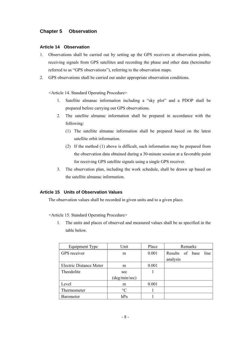
1. The units and places of observed and measured values shall be as specified in the
table below.
Equipment Type Unit Place Remarks GPS receiver m 0.001 Results of base line
analysis Electric Distance Meter m 0.001 Theodolite sec
(deg/min/sec) 1
Level m 0.001 Thermometer °C 1 Barometer hPa 1

- 9 -
2. The units and places in measuring the height of equipment shall conform to the
table below.
Equipment Type Unit Place Remarks Antenna m 0.001 Electric Distance Meter m 0.001 Theodolite m 0.001
Article 16 Performance of Survey Equipment The performance of the main equipment used in observation shall be equal or higher than
that described in the table below.
Equipment Type Performance GPS survey equipment Capable of receiving the P-codes of frequencies L1 and L2 and
AS compatible (encryption of P-codes). Electric Distance Meter Medium-range distance meter Theodolite Minimum reading value of 1" Level Automatic leveling Rod With rod level and having an accuracy of 1mm. Thermometer Having a reading accuracy of 1°C. Barometer Having a reading accuracy of 1hPa or better.
<Article 16. Standard Operating Procedure>
1. For the electric distance meter and theodolite, the total station may be used. The
data collector shall be capable of automatic input and output of observed values.
Article 17 Testing and Checking of Equipment 1. The GPS receivers, electric distance meter, theodolite and steel measure tape shall be
checked in accordance with given testing procedures before operation and, if necessary,
shall be adjusted.
2. The level, thermometer and barometer shall be checked in accordance with given testing
procedures before operation.
3. The equipment mentioned in clause 1 and clause 2 shall also be checked during the work
period if necessary.
<Article 17. Standard Operating Procedure>
1. The main equipment used for observation shall be checked before each
observation work by the personnel engaged in such work as specified in the
- 10 -
following sub-clauses:
(1) Functional check of GPS survey equipment
(a) The optical plumbing device shall operate normally.
(b) The digital display shall be normal.
(c) The antenna cable shall be normal.
(d) The connectors shall be normal.
(e) The power supply voltage shall be within the specified range.
(2) Functional check of Electric Distance Meter
(a) The optical plumbing device shall operate normally.
(b) The digital display shall be normal.
(c) The values indicating light reception, power supply voltage and others
shall be within their normal ranges as specified in the operation manual
of the electric distance meter.
(3) Functional check of theodolite
(a) The optical plumbing device shall operate normally.
(b) The rotation of each axis shall be smooth.
(c) The adjustment mechanism of the bubble tube shall be normal and
bubble movement shall be smooth.
(d) The telescope visibility control mechanism shall be normal and
visibility during observation shall not vary.
(e) The reading device for horizontal and vertical angles or the digital
display shall be normal and able to read or record the angles correctly.
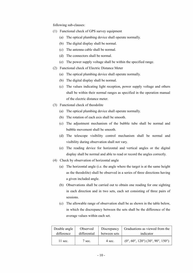
(4) Check by observation of horizontal angle
(a) The horizontal angle (i.e. the angle where the target is at the same height
as the theodolite) shall be observed in a series of three directions having
a given included angle.
(b) Observations shall be carried out to obtain one reading for one sighting
in each direction and in two sets, each set consisting of three pairs of
sessions.
(c) The allowable range of observation shall be as shown in the table below,
in which the discrepancy between the sets shall be the difference of the
average values within each set.
Double angle difference
Observed differential
Discrepancy between sets
Graduations as viewed from the indicator
11 sec. 7 sec. 4 sec. (0°, 60°, 120°) (30°, 90°, 150°)
- 11 -
(5) Check by observation of vertical angle
(a) Observations shall be carried out for three targets, each having different
heights.
(b) Observation shall be carried out to obtain one reading for one sighting
of each of the three targets and in one pair of sessions.
(c) The allowable range of observation shall be determined by the height
constant of the three targets and the discrepancy shall be within 10 sec.
(6) Functional check of total station
(a) Sub-clauses (2) and (3) shall apply accordingly.
(7) Functional check of data collector
(a) Once input, the observed values should not be able to be processed.
(b) The function of checking the observed values shall be provided.
(c) The function of re-measuring any observed value that exceeds a given
allowable range shall be provided.
(8) Functional check of level
(a) Rotation of the vertical axis shall be smooth.
(b) The adjustment mechanism of the bubble tube shall be normal and
bubble movement shall be smooth.
(c) The telescope visibility control mechanism shall be normal.
(d) The cross-hair control mechanism shall be normal.
(e) Rotation of the leveling screw shall be smooth.
(f) Rotation of the micrometer shall be smooth.
(9) Check and adjustment of level
(a) Two rods shall be erected at an interval of 30m, at the center of which
the level shall be set up to observe the elevation difference between the
two rods. The level shall then be shifted 18m if possible on the line
connecting the two rods to observe the elevation difference between the
rods again. The level shall be adjusted so that the discrepancy between
the two observed values is within 3mm.
(b) In addition to the adjustment (a) above, observations shall be carried out
with the level in a horizontal state midway between the two rods spaced
at an interval of 30m and with the level at an incline where the bubble of
the circular level is inside the concentric circle mark. The level shall
also be adjusted so that the discrepancy between the two observed
values is within 3mm.
(10) Check of leveling rods
- 12 -
(a) Each leveling rod shall be normal, with no error, peeling or striking out
of its graduation marks.
(b) The leveling screw attached to the level shall be normal.
2. Clause 2 in Article 17 shall apply to the inspection of the level during the work
period.
3. Steel measuring tapes with a scale constant of 15mm or more per 50m (at 20° and
tension of 10kg) shall not be used.
Article 18 Implementation of Observation Work GPS observations shall be implemented by the static positioning method.
<Article 18. Standard Operating Procedure>
1. In setting up the survey equipment, close attention shall be paid particularly to
centering. When centering, the leveling board shall be installed in a horizontal
place (such as on a tripod). Centering shall be checked before and after
observation and the allowable range of discrepancy before and after observation
shall be 3mm.
2. The height of the equipment shall be measured accurately along the vertical line
by the use of a measure with little elasticity. Measurements shall be made twice
each, before and after observation. The allowable range of observation
discrepancy and discrepancy before and after observation shall be 3mm.
3. GPS observations shall be carried out in accordance with the observation maps
and the observation plan.
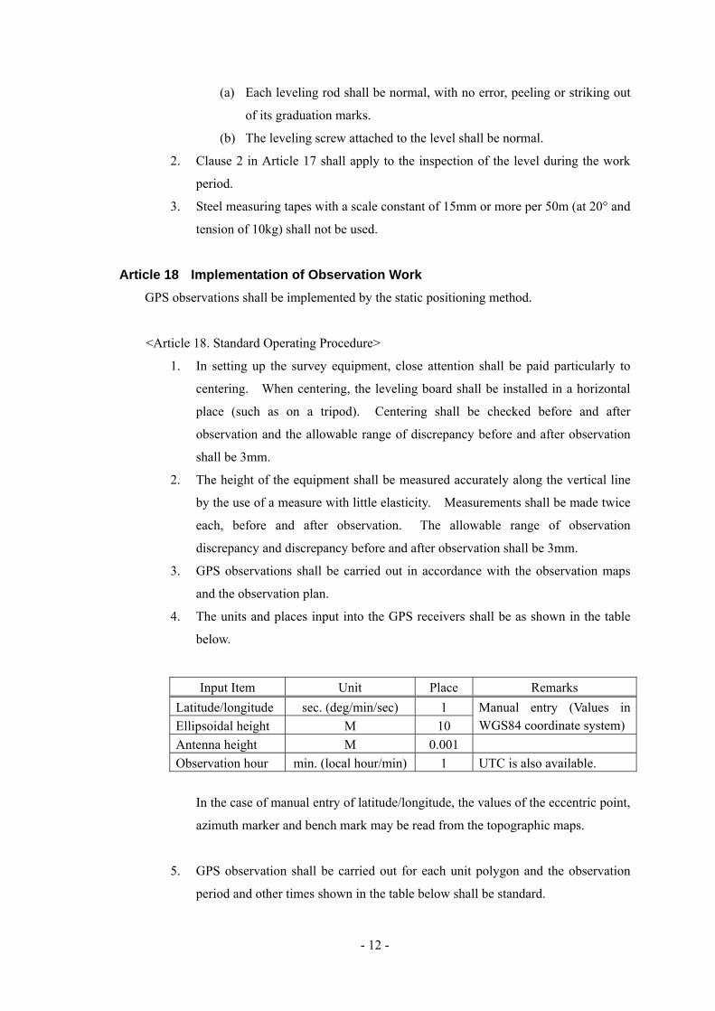
4. The units and places input into the GPS receivers shall be as shown in the table
below.
Input Item Unit Place Remarks Latitude/longitude sec. (deg/min/sec) 1 Ellipsoidal height M 10
Manual entry (Values in WGS84 coordinate system)
Antenna height M 0.001 Observation hour min. (local hour/min) 1 UTC is also available.
In the case of manual entry of latitude/longitude, the values of the eccentric point,
azimuth marker and bench mark may be read from the topographic maps.
5. GPS observation shall be carried out for each unit polygon and the observation
period and other times shown in the table below shall be standard.

- 13 -
Primary control point Secondary control point Data acquisition intervals Within 30 sec. Within 30 sec. Continuous observation period 6 hours 2 hours Number of sessions 1 1
6. GPS satellites shall be used for GPS observation as specified below.
(1) GPS satellites with an elevation angle of 15 degrees or more shall be used.
(2) GPS satellites with a normal health status shall be used.
(3) Four satellites or more shall be used simultaneously for observation.
7. GPS observation shall be carried out in strict conformity with the following rules:
(1) When installing the antenna, the specified side of the antenna or the mark
inscribed on the antenna shall be directed to the north.
(2) Any objects such as vehicles that may generate radio interference shall not
be allowed to approach within 10m of the area around the antenna.
(3) During GPS observation, no radio equipment shall be used. If unavoidable,
however, such radio equipment shall be used at a distance of 100m or more
from the antenna.
8. The GPS observed data (hereinafter referred to as “observed RAW data file”)
shall be recorded in the recording media, and in another recording media as a
backup copy.
9. The antenna height and other information necessary for GPS observations shall
be recorded in the GPS observation book.
10. Connections to benchmarks shall be carried out by the following procedure:
(1) The observation period when using GPS receivers shall be as shown in the
table below.
Data acquisition interval Within 30 sec. Continuous observation period 1 hour Number of sessions 1
(2) For direct leveling, go and back observations shall be made at a sight
distance of within 60m.
(3) Vertical angle observations in indirect leveling shall adopt the simultaneous
observation method, in which the distance between measuring stations shall
be within 3km.
(4) Clauses 3 and 4 of Article 19. Standard Operating Procedure shall apply
accordingly to measuring procedures and allowable ranges in sub-clauses (2)
and (3) above.

- 14 -
11. The operating conditions of GPS observations (including the tripod and GPS
antenna tower) shall be photographed for later verification.
Article 19 Measurement of Eccentric Elements If there is an eccentric point in a GPS observation, the eccentric elements shall be measured
by the procedure described below.
<Article 19. Standard Operating Procedure>
1. The eccentric elements shall be measured as follows:
(1) The observation procedure and allowable ranges of the eccentric angles
shown in the table below shall be standard.
Eccentric angle observation procedure
Allowable range Eccentric distance (e) Measuring Instruments Double angle
difference Observed difference
Adoption of eccentric angle
Unit (φ)
Less than 2m trilateration using measuring paper (2 sessions) 30' 2m or more, and less than 7m 5' 7m or more, and less than 20m
3' 2' 1'
20m or more, and less than 100m 2 pairs of sessions
50" 40" 30" 100m or more and less than 500m 3 pairs of sessions 20" 15" 5"
500m or more
Theo
dolit
e
3 pairs of sessions (2 sets); Discrepancy between sets: 4"
11" 7" 1"
The graduations as viewed from the indicator in 2 sets of observations shall
be (0°, 60°, 120°) and (30°, 90°, 150°).
(2) The measuring procedure and allowable range of the eccentric distance
shown in the table below shall be standard.
Eccentric distance (e) (measured) Measuring instrument Less than 30cm Ruler 30cm or more and less than 50cm Steel tape Minimum measuring distance or more Electric distance meter or total
station
2. When using a steel tape for measuring the eccentric distance, the following
procedure shall be adopted:
(1) Two sets of measurements shall be taken, one set consisting of two
measuring sessions. In the second set of measurements, the persons doing
the measuring at the front and back shall change places.
- 15 -
(2) The temperature shall be measured at each set of observations.
(3) The allowable range of discrepancy between sets shall be 1/10,000 of the
measured distance. However, the allowable range of discrepancy shall be
2mm when the measuring distance is 20m or less.
3. Measurement of the eccentric distance using an electric distance meter or total
station shall be made according to the following procedure:
(1) Three sets of measurements shall be made, one set consisting of two
measuring sessions. The measuring interval between sets shall be 5
minutes or more. Furthermore, targeting shall be repeated at each set.
(2) Measurement of climatic factors shall be made at the instrument station and
the reflection station at the beginning of each set of observations. In this
case, the value on one side may be obtained by calculation instead of
measurement. If the elevation difference is less than 400m, the
measurement may be made at only one side. The temperature measurement
shall be made at a distance of 1.5m or more from planimetric features,
vegetation and the ground.
(3) The allowable range of the measured values shall be a discrepancy of 5mm
within the set, and the discrepancy between sets after climatic correction
shall be 5mm.
(4) The measurements shall be verified by changing the instrument height or by
another method.
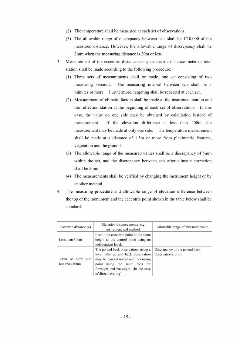
4. The measuring procedure and allowable range of elevation difference between
the top of the monument and the eccentric point shown in the table below shall be
standard.
Eccentric distance (e) Elevation distance measuring
instrument and method Allowable range of measured value
Less than 30cm Install the eccentric point at the same height as the control point using an independent level.
—
30cm or more and less than 100m
The go and back observations using a level. The go and back observation may be carried out at one measuring point using the same rods for foresight and backsight. (In the case of direct leveling)
Discrepancy of the go and back observations: 2mm

- 16 -
Eccentric distance (e) Elevation distance measuring
instrument and method Allowable range of measured value
Vertical angle observations in the forward and backward directions using a theodolite or total station. One-way vertical observations may be made at different instrument heights instead of the forward and backward vertical observation. (In the case of indirect leveling.)
Discrepancy of height constants: Eccentric distance: less than 10m: 40 sec. 10m or more: 25 sec. Forward and backward discrepancy of elevation difference or discrepancy between 2 sessions: 5mm
The go and back observations using a level. (In the case of direct leveling)
Discrepancy of the go and back observations: less than 300m: 3mm 300m or more: 5mm√S S: Measured distance (km)
100m or more
Vertical angle observation in the forward and backward directions using a theodolite or total station. (In the case of indirect leveling)
Discrepancy of height constants: Eccentric distance: less than 500m: 12 sec. 500m or more: 9 sec. Discrepancy of elevation differences in forward and backward directions: 15mm
Vertical angle observations shall be made to obtain one reading for one sighting
in each direction and in two sets, each set consisting of one pair of sessions.
5. Article 18. Standard Operating Procedure (excluding clause 4) shall apply to the
observation procedure when the azimuth markers are installed, but the continuous
observation period using the static positioning method shall be 3 hours.
6. In the case of an eccentric bench mark, observations to connect to bench marks
shall be made in accordance with the measuring procedure in clause 4 of Article
18. Standard Operating Procedure.
- 17 -
Chapter 6 Calculations
Article 20 Calculations The coordinates of the control points, ellipsoidal height and related factors shall be
calculated.
<Article 20. Standard Operating Procedure>
1. The calculations shall be made in accordance with the national control point
survey calculation formula. However, other calculation formulas may be used if
it ensures accuracy equal to or higher than these formulas.
2. Trial computations shall be carried out to check that the programs on the
computer used for the calculations are accurate and error-free.
3. The observation RAW data files shall be converted into RINEX format
(hereinafter referred to as “observation RINEX data file”) and stored in the
recording medium. This recording medium shall be used for subsequent
calculations.
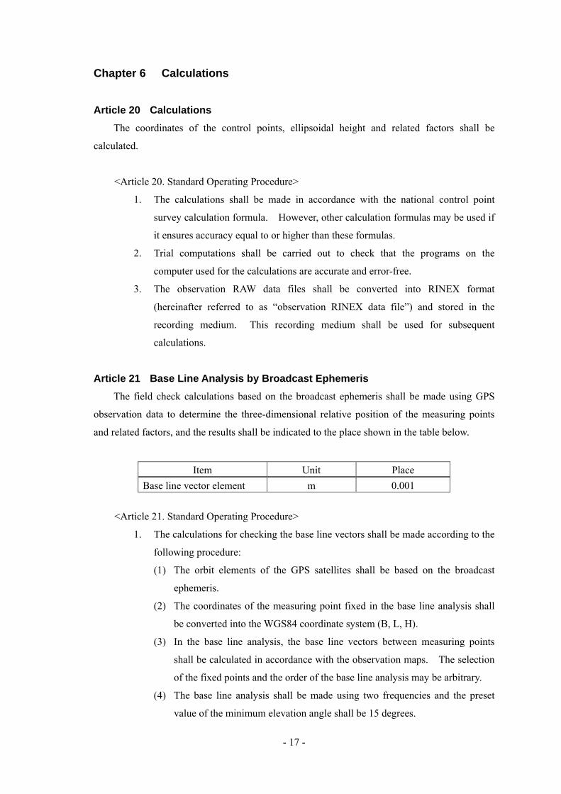
Article 21 Base Line Analysis by Broadcast Ephemeris The field check calculations based on the broadcast ephemeris shall be made using GPS
observation data to determine the three-dimensional relative position of the measuring points
and related factors, and the results shall be indicated to the place shown in the table below.
Item Unit Place Base line vector element m 0.001
<Article 21. Standard Operating Procedure>
1. The calculations for checking the base line vectors shall be made according to the
following procedure:
(1) The orbit elements of the GPS satellites shall be based on the broadcast
ephemeris.
(2) The coordinates of the measuring point fixed in the base line analysis shall
be converted into the WGS84 coordinate system (B, L, H).
(3) In the base line analysis, the base line vectors between measuring points
shall be calculated in accordance with the observation maps. The selection
of the fixed points and the order of the base line analysis may be arbitrary.
(4) The base line analysis shall be made using two frequencies and the preset
value of the minimum elevation angle shall be 15 degrees.
- 18 -
(5) The climatic correction shall be based on the standard atmosphere used by
the base line analysis software.
(6) In principle, the cyclic slips shall be automatically compiled using the base
line analysis software.
(7) After the base line analysis has been carried out, the internal accuracy shall
be examined according to statistical indices (such as the standard deviation
and data rejection rate).
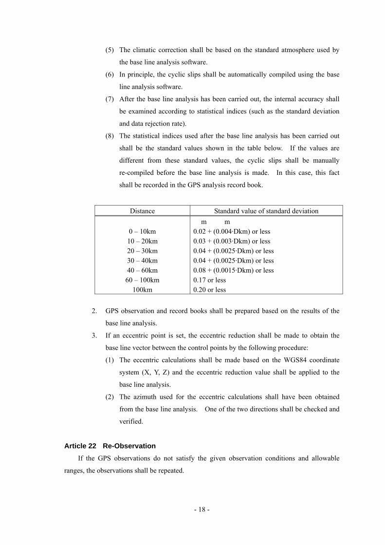
(8) The statistical indices used after the base line analysis has been carried out
shall be the standard values shown in the table below. If the values are
different from these standard values, the cyclic slips shall be manually
re-compiled before the base line analysis is made. In this case, this fact
shall be recorded in the GPS analysis record book.
Distance Standard value of standard deviation
0 – 10km 10 – 20km 20 – 30km 30 – 40km 40 – 60km
60 – 100km 100km
m m 0.02 + (0.004·Dkm) or less 0.03 + (0.003·Dkm) or less 0.04 + (0.0025·Dkm) or less 0.04 + (0.0025·Dkm) or less 0.08 + (0.0015·Dkm) or less 0.17 or less 0.20 or less
2. GPS observation and record books shall be prepared based on the results of the
base line analysis.
3. If an eccentric point is set, the eccentric reduction shall be made to obtain the
base line vector between the control points by the following procedure:
(1) The eccentric calculations shall be made based on the WGS84 coordinate
system (X, Y, Z) and the eccentric reduction value shall be applied to the
base line analysis.
(2) The azimuth used for the eccentric calculations shall have been obtained
from the base line analysis. One of the two directions shall be checked and
verified.
Article 22 Re-Observation If the GPS observations do not satisfy the given observation conditions and allowable
ranges, the observations shall be repeated.
- 19 -
Article 23 Field CheckCalculations After completion of GPS observations and base line analysis based on the broadcast
ephemeris, check calculations for accuracy control shall promptly be made.
<Article 23. Standard Operating Procedure>
1. Check calculations of base line vector
(1) A base line analysis between two points of each unit polygon shall be made
using the data for half the time of the continuous observation period in one
session, and the coordinate difference between the two results shall be
compared (to obtain the primary control point). However, this method shall
not apply to observations for benchmark connections or for azimuth marker
installation.
(2) If the cyclic slip is compiled manually in the base line analysis, the circuit
closure calculation of the base line vector elements in the unit polygon shall
be made to check the closure errors.
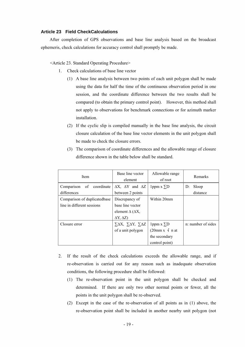
(3) The comparison of coordinate differences and the allowable range of closure
difference shown in the table below shall be standard.
Item Base line vector
element Allowable range
of root Remarks
Comparison of coordinate differences
∆X, ∆Y and ∆Z between 2 points
1ppm x ∑D D: Sloop distance
Comparison of duplicatedbase line in different sessions
Discrepancy of base line vector element ∆ (∆X, ∆Y, ∆Z)
Within 20mm
Closure error ∑∆X, ∑∆Y, ∑∆Z of a unit polygon
1ppm x ∑D (20mm x √n at the secondary control point)
n: number of sides
2. If the result of the check calculations exceeds the allowable range, and if
re-observation is carried out for any reason such as inadequate observation
conditions, the following procedure shall be followed:
(1) The re-observation point in the unit polygon shall be checked and
determined. If there are only two other normal points or fewer, all the
points in the unit polygon shall be re-observed.
(2) Except in the case of the re-observation of all points as in (1) above, the
re-observation point shall be included in another nearby unit polygon (not
- 20 -
observed) to form a new unit polygon and GPS observation shall be
performed at the re-observation point.
3. If any change appears in the unit polygon by re-observation, the net adjustment
map shall also be changed accordingly.
Article 24 Base Line Analysis by Precise Ephemeris Base line analysis shall be carried out using the precise ephemeris with the GPS
observation stations as fixed points to determine their geodetic coordinates.
<Article 24. Standard Operating Procedure>
1. Calculations shall be made for each unit polygon. If the net adjustment map is
changed due to re-observation, the calculations shall be based on the new net
adjustment map.
2. Base line analysis calculations by the precise ephemeris shall be made in
accordance with the International Earth Rotation Service(IERS) Terrestrial
Reference Frame Coordinate System (hereinafter referred to as “ITRF (IERS
Terrestrial Reference Frame) coordinate system”). The results of the
calculations shall be stored in the recording medium as a “precise analysis result
file”.
3. For an eccentric point, re-calculations shall be made based on the ITRF
coordinate system in accordance with clause 3 of Article 22. Standard Operating
Procedure.
4. The results using the ITRF coordinate system shall be converted into the final
results of the WGS84 coordinate system (B, L, H). In this case, the ellipsoidal
height shall be used.
5. The X, Y and Z components of the final results shall be indicated to 0.0001m.
Article 25 Adjustment Computation After completion of the check calculations, the geodetic coordinates and elevations shall be
determined by adjustment computation.
<Article 25. Standard Operating Procedure>
1. Adjustment computation shall be made in accordance with the three-dimensional
network adjustment computation program.
2. Three-dimensional network adjustment computation (hereinafter referred to as
“adjustment computation”), in which a point is fixed, shall be performed by the
following procedure:
- 21 -
(1) The adjustment computation shall be performed using all the base lines on
the net adjustment map. If some base lines are duplicated, as a rule, the
base line first observed shall be used.
(2) In the adjustment computation, a point whose elevation was connected to a
bench mark shall be used as the fixed point.
(3) In the adjustment computation, the input data (i.e. latitude, longitude and
height of a new point) shall have been obtained from the base line analysis.
(4) The allowable range of the computation results shown in the table below
shall be standard.
Type Allowable range RemarksCorrected values of ∆X, ∆Y and ∆Z components 10mm
(5) The final results of the computation shall be values based on the WGS84
coordinate system.
(6) The adjustment computation shall be performed using a given calculation
formula and the results shall be expressed as shown in the table below.
Item Unit Place Remarks Latitude/longitude Sec
(deg/min/sec) 0.0001
Elevation m 0.01 0.001
In direct leveling
UTM coordinates m 0.001 Azimuth Sec
(deg/min/sec) 0.1
Distance m 0.001
Article 26 Preparation of Point Description A point description shall be prepared for all the control points used in the GPS
observations.
<Article 26. Standard Operating Procedure>
1. The antenna height as well as the necessary items shall be included in the point
description for each control point. Furthermore, the position of eccentric points
with an eccentric distance of 10m or more shall be indicated on the sketch map.
2. “National control point survey” shall be entered in the Remarks column.
- 22 -
Chapter 7 Arrangement
Article 27 Arrangement All the survey results and records shall be arranged and classified into observation RAW
data files, observation RINEX data files, precise analysis result files, observation books, GPS
analysis books, calculation books, point descriptions, accuracy control sheets, national control
point survey network maps and a control point distribution map.
<Article 27. Standard Operating Procedure>
1. The national control point survey network maps shall be created on
1/250,000-scale topographic maps based on the plans of net adjustment. (The
eccentric points, antenna heights, benchmarks and GPS observation stations shall
also be entered on the maps.)
2. The control point distribution maps shall be created on 1/250,000-scale
topographic maps.
CALCULATION FORMULAE FOR
NATIONAL CONTROL POINT SURVEY
1. Transformation of Ellipsoid (1) Parameter of Ellipsoidal
(a) Values used by Clarke 1880
Semi-major axis: ab=6378249.145m
Flattening: fb=1/293.465000
(b) Values used by GPS (WGS84)
Semi-major axis: aw=6378137m
Flattening: fw=1/298.257223563
(2) Transformation from latitude, longitude and height to a 3-dimensional rectangular
coordinate system
( )( )( ) ( )
( )f2fe
sine1/a
sinHeN
sincosHNcoscosHN
2
22
2
−=
•−=Ν
+−=Ζ
λ•+=Υλ•+=Χ
φ
φ
φ
φ
where
φ: Latitude λ: Longitude
H : Height from the ellipsoid N : Radius of curvature of prime vertical
a : Semi-major axis e : First eccentricity
f : Flattening
(3) Transformation from a 3-dimensional rectangular coordinate system to latitude,
longitude and height
( )( )
( )( ) 1-111
2
1-122
1-1
22
1
coseP/tan
sine-1a/
N-cos/PHYXP
/tan
1 φφ
φ
φ
•Ν•−Ζ=
•=Ν
=
+=
ΧΥ=λ
−
−
−
(φis repeatedly calculated.)
where
Convergence condition of φ: φ1-φ1-1 ≦10-12(rad)
φ1 : ith computation result
φ0: tan-1 (Z/P)
(4) Transformation of coordinates
(a) General formula for transformation from Gambian’s geodetic coordinate system
to WGS84 coordinate system
( )
ΖΥΧ
Ω−Ω+Ω+Ω−Ω−Ω+
∆++
∆Ζ∆Υ∆Χ
=
ΖΥΧ
Β
Β
Β
ΧΥ
ΧΖ
ΥΖ
11
11
0
0
0
w
w
w
where
XB, YB, ZB : UTM coordinates values based on Gambian’s geodetic
coordinate system (Clarke ellipsoid)
Xw, Yw, Zw : UTM coordinates valued based on WGS84 coordinate
system
ΔX0, ΔY0, ΔZ0 : Value of parallel shift of origin from Gambian’s geodetic
coordinate system to WGS84 coordinate system
Δ : Value of scale correction from Gambian’s geodetic
coordinate system to WGS84 coordinate system
Ωx, Ωy, Ωz : Rotation of the X, Y, Z-axis from Gambia’s geodetic
coordinate system to WGS84 coordinate system
(b) Actual method of transformation
2. Eccentric Reduction Calculation 2.1 Eccentric reduction calculation
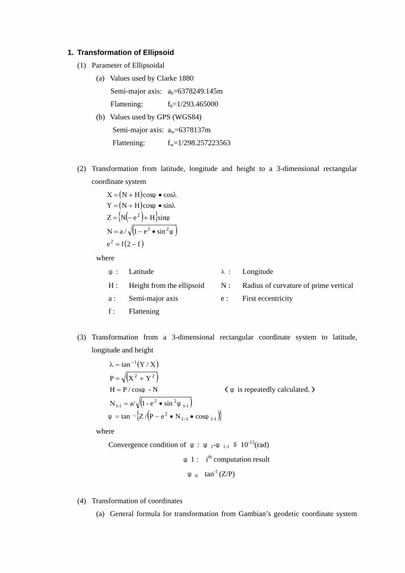
(1) Correction computation of elevation angle necessary for eccentric reduction
computation
( ) ( ) D/'cosfEEisind
'D/'cosfEEisind
d'd'
211221
2
122111
1
222
111
′α•−+−=α
α•−+−=α
α+α=αα+α=α
−
−
where
α1, α2 : Elevation angle of measured line from each survey point
α1’, α2’ : Observed elevation angles
dα1, dα2 : Correction of elevation angles of measured line
D’ : Measured Slope distance
E1, E2 : Height of Electric distance meter or reflecting mirror at the time
each point is observed
i1, i2 : Height of theodolite
f1, f2 : Height of target
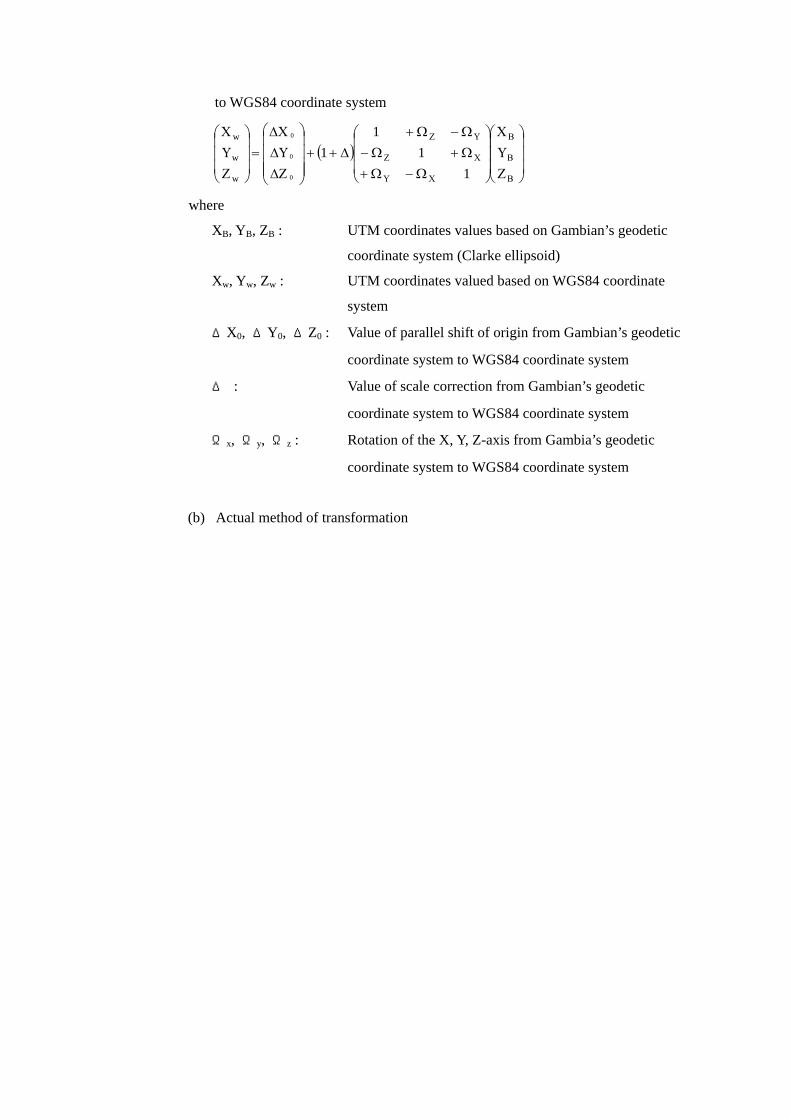
(2) Distance calculation necessary for eccentric reduction calculation
( ) ( )
2/
fisinDcosDD
21m
221m
2m
′−′=
−+•′+•′=
ααα
αα
where
D : Slope distance of known
station and eccentric station
D’ : Measured slope distance
α1’, α2’ : Observed elevation angles
i1, i2 : Height of instrument
f1, f2 : Height of target
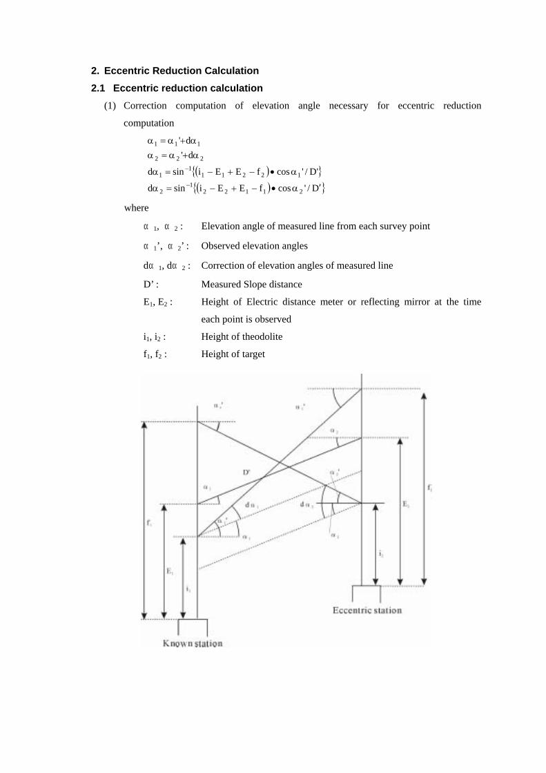
(3) Correction computation of elevation angle necessary for eccentric reduction calculation
( ) ( ) D/'cosfisind
D/'cosfisind
d'd'
2121
2
1211
1
22
111
2
α•−=α
α•−=α
α+α=αα+α=α
−
−
where
α1, α2 : Elevation angles of known station and eccentric station
α1’, α2’ : Observed elevation angles
dα1, dα2 : Correction value of elevation angles
D : Slope distance of known
station and eccentric station
i1, i2 : Height of instrument
f1, f2 : Height of target
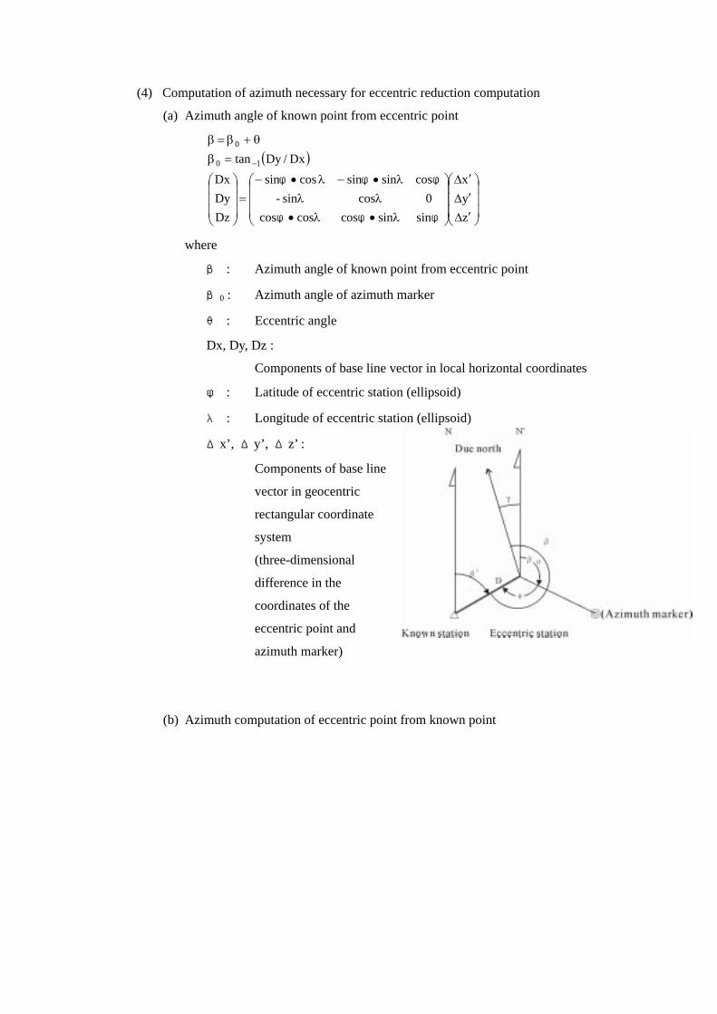
(4) Computation of azimuth necessary for eccentric reduction computation
(a) Azimuth angle of known point from eccentric point
( )
′∆
′∆
′∆
λ•λ•λλ
λ•−λ•−=
=βθ+β=β
−
zyx
sinsincoscoscos0cossin-
cossinsincossin
DzDyDx
Dx/Dytan 10
0
φφφ
φφφ
where
β : Azimuth angle of known point from eccentric point
β0 : Azimuth angle of azimuth marker
θ : Eccentric angle
Dx, Dy, Dz :
Components of base line vector in local horizontal coordinates
φ : Latitude of eccentric station (ellipsoid)
λ : Longitude of eccentric station (ellipsoid)
Δx’, Δy’, Δz’ :
Components of base line
vector in geocentric
rectangular coordinate
system
(three-dimensional
difference in the
coordinates of the
eccentric point and
azimuth marker)
(b) Azimuth computation of eccentric point from known point
( )
( )( )
( )( ) ( )2222
22c
c
21m
21m
1
m
c
0
sine1/e1a
sine1/a
R
2/2/
cosS/c
HmR/RcosDSNc/tansinS
180
φ•−−=Μ
φ•−=Ν
Ν•Μ=
Η+Η=Ηα−α=αΒ′•′=ΧΜΧ+=
+•α•=′φ•β′•′=γ
γ−±β=β′
φφ
where
β : Azimuth angle of known point from eccentric point (The values
calculated in 2.1, (4) (a). shall be used)
γ : Meridian convergence angle
S’ : Distance on reference surface (on the ellipsoid)
D : Slope distance of known point and eccentric point
φ1 : Latitude of the known point (on the ellipsoid)
Nc : Radius of curvature of the prime vertical (on the ellipsoid: the
argument shall be φc.)
M: Radius of curvature of the meridian (on the ellipsoid: argument shall
be φ1.)
R: Average radius of curvature (on the ellipsoid: argument shall be φ1.)
α1, α2: Elevation angle of known point and eccentric point
H1, H2: Height of known point and eccentric point (on the ellipsoid)
Note: The calculation of γ shall be made with the value of β0’=β+180°
and repeated until |β-β0’|≦0.1” is satisfied.
(5) Eccentric reduction computations (The transformation of the base line vector
components in the local horizontal coordinate system to the geocentric rectangular
coordinate system)
( ) 2/sinD
sincosDcoscosD
sin0cossincoscossinsincoscossincossin
zyx
21m
m
m
m
α−α=α
α•β•α•β•α•
λ•λλ•−λ•λ−λ•−
=
∆∆∆
φφ
φφ
φφ
where

Δx, Δy, Δz : Three-dimensional eccentric reduction
φ : Latitude of known point (on the ellipsoid)
λ : Longitude of known point (on the ellipsoid)
D : Slope distance of known station and eccentric station
α1, α2 : Elevation angle of known station and eccentric station
β : Azimuth angle of eccentric point from known point or known point
from eccentric point (on the ellipsoid)

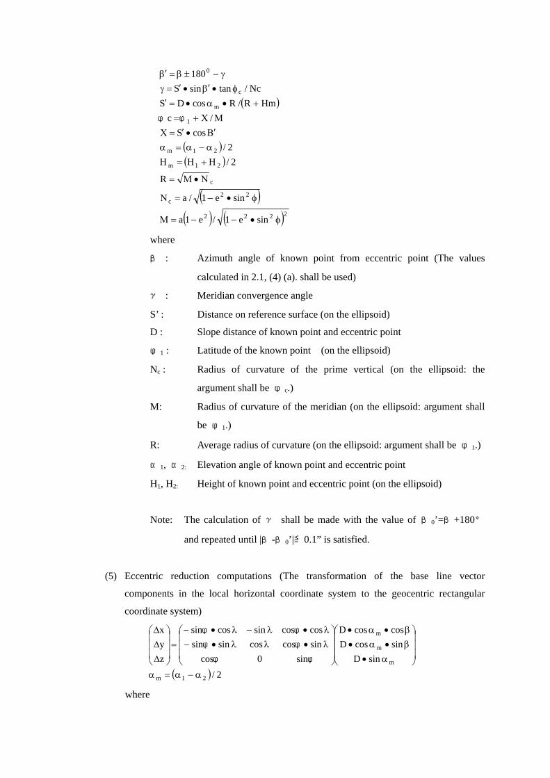
2.2 Method of eccentric reduction (1) Eccentric observations performed at the eccentric points and known points
∆∆∆
±
∆Ζ∆Υ∆Χ
=
∆Ζ∆Υ∆Χ
zyx
ob
ob
ob
where
ΔX, ΔY, ΔZ : Three-dimensional
coordinate difference
between the two points after
eccentric reduction
(Components in the
geocentric rectangular
coordinate system)
ΔXob, ΔYob, ΔZob : Three-dimensional coordinate difference
between the two points observed at the
eccentric point (Components in the
geocentric rectangular coordinate system)
Δx, Δy, Δz : Eccentric reduction (The values
calculated in 2.1, (5) “Eccentric reduction
computation” shall be used.)
(2) For eccentric points with unknown coordinates
∆∆∆
±
ΖΥΧ
=
ΖΥΧ
zyx
1
1
1
where
X, Y, Z: Three-dimensional coordinates of eccentric point (Components in
the geocentric rectangular coordinate system)
X1, Y1, Z1: Three-dimensional coordinates of known point (Components in
the geocentric rectangular coordinate system)
Δx, Δy, Δz : Eccentric reduction (The values calculated in 2.1, (5) “Eccentric
reduction computation” shall be used.)
∆Ζ∆Υ∆X
∆Ζ∆Υ∆Χ
ob
ob
ob
Observation direction
∆Ζ∆Υ∆X
Known station Eccentric station
∆∆∆
zyx
Known station Eccentric station

3. Computation of Closed Vector
Closed vectors: (∑ΔX、∑ΔY、∑ΔZ)
where
ΔX, ΔY, ΔZ : Three-dimensional difference between the coordinates of the
two points after eccentric reduction (Components in the
geocentric rectangular coordinate system)
4. Computation of Elevation (1) Elevation angle: when using the mean of face left and face right readings
( ) ( ) 212112 EER2/Dsec2/1sinD −+′α−α•′+Η=Η
(2) Elevation angle: in the case of separate computation in face left and face right readings
( )( )133.0k
R2/Dk1
2/"'sinD"sinD'
2D
222
D12212
D21112
=−=Κ
Η+Η=ΗΚ−Ε+Ε−α•′−Η=Η
Κ+Ε+Ε+α•′+Η=Η
(反方向)
(正方向)
Κ
Κ
where
H1, H2 : Elevation of each survey point
D’ : Measured slope distance
E1, E2 : Height of Electric distance meter or reflecting mirror at the time each
survey point is observed
α1, α1 : Elevation angle to measured line from each survey point
KD : Correction for earth’s curvature and refraction
K : Refraction coefficient
R : Earth’s radius (6,370km)
(face left) (face right)

5. Base Line Analysis 5.1 Net Adjustment
( ) ( )( )
1
zzyzxz
zyyyxy
zxyxxx1
T1T
TT
BP
PLAPAAX
PLAXPAA
LAXV
−
−
−
∆∆σ∆∆σ∆∆σ∆∆σ∆∆σ∆∆σ∆∆σ∆∆σ∆∆σ
==
=
=
−=
where
V: Residual vector
A: Coefficient matrix of unknown parameters
X: Vector of unknown parameters
L: Vector of constant term
P: Weight matrix
B: Variance-covariance matrix of ΔX, ΔY and ΔZ
5.2 Relation of variance-covariance matrix and correlation matrix
( )jjiiijij / σσσρ ×=
5.3 Correlation matrix
∆∆ρ∆∆ρ∆∆ρ∆∆ρ∆∆ρ∆∆ρ
=1
11
C
yzxz
zyxy
zxyx
5.4 Standard deviation
Standard deviation ofΔX :
Standard deviation of ΔY :
Standard deviation of ΔZ :
Standard deviation of slope distance (D) :
( )222
TDD
D
D/Z,D/,D/GGBG
∆Ζ+∆Υ+∆Χ=
∆∆Υ∆Χ=••=σ
where
B : Variance-covariance matrix of ΔX, ΔY and ΔZ
( )( )( )( )DD
zz
yyy
xxx
D
z
σ=σ
∆∆σ=∆σ
∆∆σ=∆σ
∆∆σ=∆σ

6. Others In addition to these formulas, formulas that are confirmed to have equal or greater accuracy
may also be used.