national crane 600h series -...
TRANSCRIPT

National Crane 600H SeriesProduct Guide
Features
• 18,1 t (20 USt) rating
• Six boom options available from 11,58 m (38 ft) to 27,42 m (90 ft)
• Full-, mid-, and retracted-span outriggers
• Mentor LMI System
• Internal anti-two block wiring
• Standard and rear mount options

Features
Overload protectionMentor Load Moment Indicator (LMI) with work area definition system (WADS) is standard on all Series 600H machines. The LMI display console is weatherproof and displays all crane load lifting values simultaneously.
"HO"-style outriggersStandard Mount: Two sets of “HO”-style outriggers with 5,28 m (17 ft 4 in) span, with 3,04 m (10 ft) mid span setting with manual locks and reduced capacity chart and fully retracted outrigger spread with reduced capacity chart.
Rear Mount: 4.7 m (15.3 ft) full span, with 4,05 m (13.3 ft) midspan setting with manual locks and reduced capacity chart and fully retracted outrigger spread with reduced capacity chart.
Main outriggers are equipped with removable ball and socket aluminum foot pads standard.
BoomAt 27,5 m (90 ft) the 600H series four-section boom is the longest in its size range. The longer boom allows the operator to perform more lifts without the use of a jib, reducing setup time and improving efficiency. A 11,58 m (38 ft) three-section boom, 15 m (49 ft) four-section boom, 18,3 m (60 ft) three-section boom, 21,64 (71 ft) three-section boom, and 24,38 m (80 ft) four-section boom are also available.
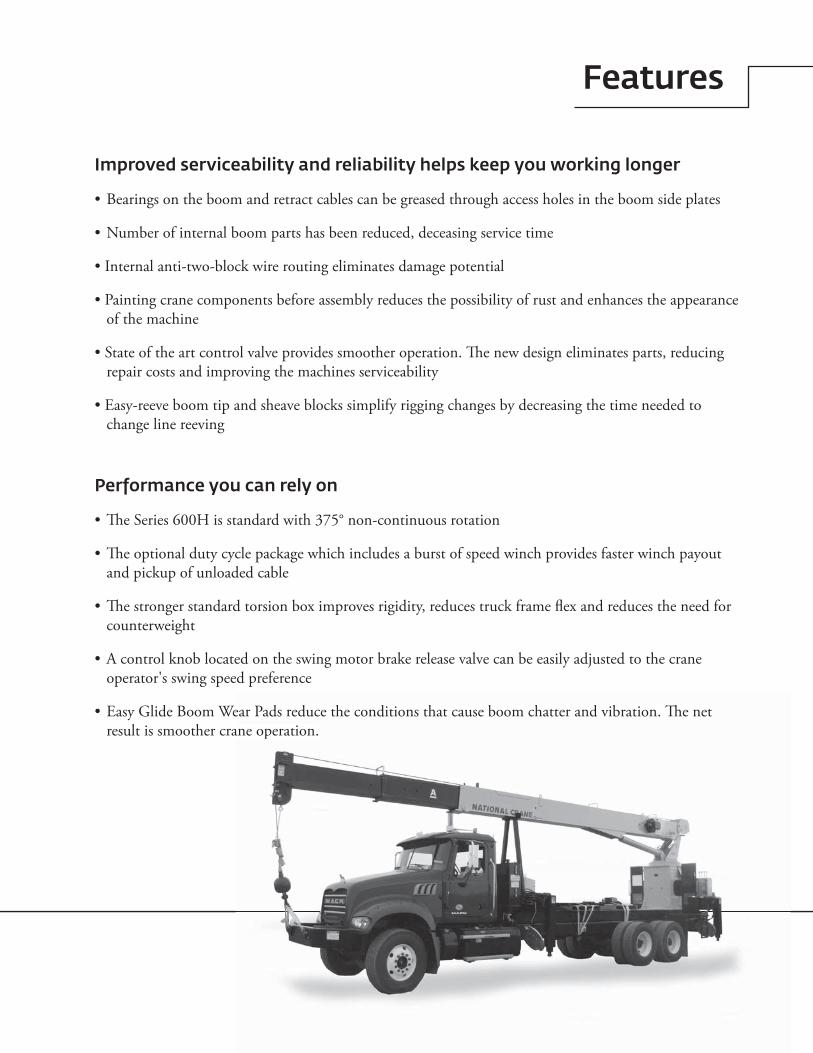
National Crane Series 600H• 18,1 t (20 USt) maximum capacity• 30,2 m (99 ft) maximum tip height (main boom)• 43,95 m (144 ft) maximum tip height (boom with jib)
Features
Improved serviceability and reliability helps keep you working longer
• Bearings on the boom and retract cables can be greased through access holes in the boom side plates
• Number of internal boom parts has been reduced, deceasing service time
• Internal anti-two-block wire routing eliminates damage potential
• Painting crane components before assembly reduces the possibility of rust and enhances the appearance of the machine
• State of the art control valve provides smoother operation. The new design eliminates parts, reducing repair costs and improving the machines serviceability
• Easy-reeve boom tip and sheave blocks simplify rigging changes by decreasing the time needed to change line reeving
Performance you can rely on
• The Series 600H is standard with 375° non-continuous rotation
• The optional duty cycle package which includes a burst of speed winch provides faster winch payout and pickup of unloaded cable
• The stronger standard torsion box improves rigidity, reduces truck frame flex and reduces the need for counterweight
• A control knob located on the swing motor brake release valve can be easily adjusted to the crane operator's swing speed preference
• Easy Glide Boom Wear Pads reduce the conditions that cause boom chatter and vibration. The net result is smoother crane operation.
ear Pads reduce the conditions that cause boom chatter and vibration. The net ane operation.
4
Contents
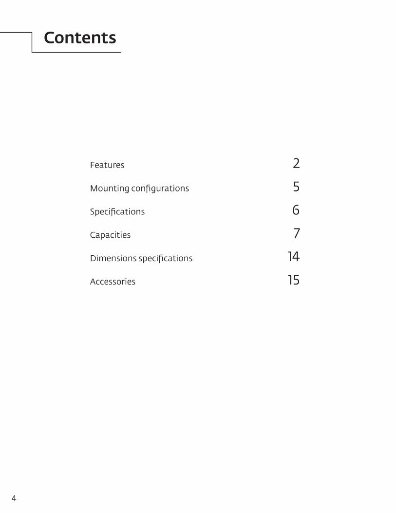
Features 2
Mounting configurations 5
Specifications 6
Capacities 7
Dimensions specifications 14
Accessories 15

5National Crane 600H
Mounting configuration
Configuration 1 with torsion box – 180˚ full capacity work areaWorking area ............................................................................. 180˚Gross axle weight rating front ........................... 6350 kg (14,000 lb)Gross axle weight rating rear .......................... 15,442 kg (34,000 lb)Gross vehicle weight rating ............................ 21,773 kg (48,000 lb)Wheelbase .............................................................. 650 cm (256 in)Cab to axle/trunnion (CA/CT) ............................... 488 cm (192 in)Frame Section Modulus (SM) under crane: 758 MPa (110,000 PSI) .................................... 327,7 cm3 (20 in3)Frame Section Modulus (SM) over rear stabilizers: 758 MPa (110,000 PSI) ....................................... 213 cm3 (13 in3)Stability weight, front ....................... 3946 kg (8700 lb) minimum*Stability weight, rear .......................... 3901 kg (8600 lb) minimum*
Configuration 2 with torsion box – 360˚ full capacity work areaWorking area .............................................................................360˚Gross axle weight rating front ........................... 6350 kg (14,000 lb)Gross axle weight rating rear .......................... 15,422 kg (34,000 lb)Gross vehicle weight rating ............................ 21,773 kg (48,000 lb)Wheelbase .............................................................. 650 cm (256 in)Cab to axle/trunnion (CA/CT) ............................... 488 cm (192 in)Frame Section Modulus (SM) under crane: 758 MPa (110,000 PSI) ....................................... 328 cm3 (20 in3)Frame Section Modulus (SM) over rear stabilizers: 758 MPa (110,000 PSI) ........................................ 213 cm3 (13 in3)Stability weight, front ........................ 3946 kg (8700 lb) minimum*Stability weight, rear ...........................3901 kg (8600 lb) minimum*
Configuration 3 with torsion box – rear mountWorking area .............................................................................360˚Gross axle weight rating front ............................ 5443 kg (12,000 lb)Gross axle weight rating rear .......................... 15,422 kg (34,000 lb)Gross vehicle weight rating ............................ 20,865 kg (46,000 lb)Wheelbase ............................................................... 650 cm (256 in)Cab to axle/trunnion (CA/CT) ................................ 488 cm (192 in)Frame Section Modulus (SM) under crane: 758 MPa (110,000 PSI) ....................................... 261 cm3 (15.9 in3)Frame Section Modulus (SM) over rear stabilizers: 758 MPa (110,000 PSI) ....................................... 261 cm3 (15.9 in3)Stability weight, front ........................ 2948 kg (6500 lb) minimum*Stability weight, rear .......................... 4309 kg (9500 lb) minimum*
44.69"
104.31"20' Bed
92.55" 118.78"
Top of truck frame rail
Tandem
66.00"
111.0" MIN
192.00" MIN
256.00" WB MIN
6.00" MIN
Front jack required for 360° work area
44.69"
104.31"20' Bed
92.55" 118.78"
Top of truck frame rail
Tandem
66.00"
111.0" MIN
192.00" MIN
256.00" WB MIN
6.00" MIN
2.19"MIN
23.00"
256.00"MIN
192.00"MIN
129.00"
78.00"
118.72"
92.49"
44.69"
16' Bed
Top of truck frame rail
Tandem
Notes:• Gross Vehicle Weight rating (GVWR) is dependent on all
components of the vehicle (axles, tires, springs, frame, etc.) meeting manufacturers’ recommendations: always specify GVWR when purchasing trucks
• Diesel engines require a variable speed governor and energize-to-run fuel solenoid for smooth crane operation; electronic fuel injection requires EET engine remote throttle
• All mounting data is based on a National Series 600H with an 85 percent stability factor
• The complete unit must be installed in accordance with factory requirements, and a test performed to determine actual stability and counterweight requirements per SAE J765; contact the factory for details
• Transmission neutral safety interlock switch is required with optional radio remote control
*Estimated axle scale rates prior to installation of crane, stabilizers and subbase for 85% stability.
The configurations are based on the Series 600H with an 85% stability factor. The complete unit must be installed in accordance with factory requirements and a test performed to determine actual stability and counterweight requirements since individual truck chassis vary.
This configuration is the least expensive method for the Model 600H. This mount, with the crane mounted behind the cab, requires the least weight of all mounts for stability; thus, you can haul larger payloads on your truck. It requires standard subbase and rear (ASH) stabilizers. *Weights do not include RSOD, PTO, pumpt, bed and SFO.
Requires front SFO stabilizer to give machine full capacity 360˚ around the truck. Truck must meet the minimum requirements above. Front stabilizer gives the machine a solid base, helping the operator control loads precisely. Extended front frame rails required for SFO installation. *Weights do not include RSOD, PTO, pumpt, bed and SFO.
Allows the installation of the Model 600H on a chassis. In most cases, the chassis will not require reinforcing, and the amount of counterweight required is minimized, increasing payload capacities. *Weights do not include RSOD, PTO, pumpt, bed and SFO.
6
Specifications
Boom and jib combinations data
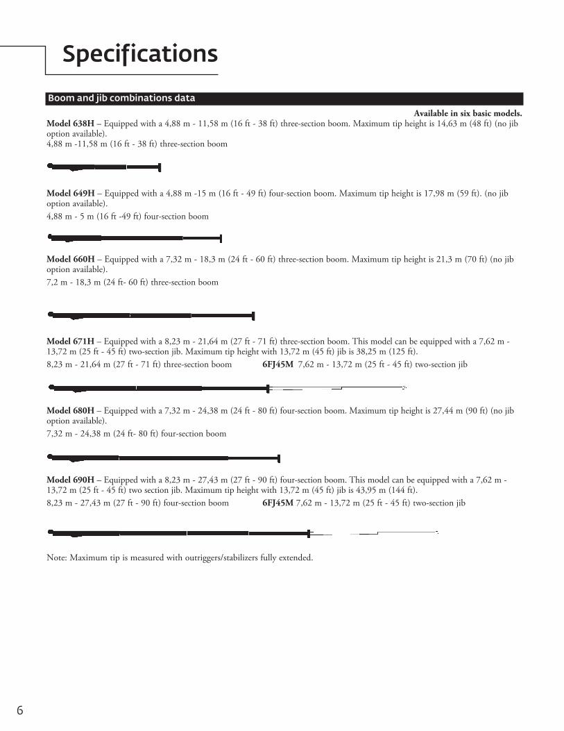
Available in six basic models.Model 638H – Equipped with a 4,88 m - 11,58 m (16 ft - 38 ft) three-section boom. Maximum tip height is 14,63 m (48 ft) (no jib option available). 4,88 m -11,58 m (16 ft - 38 ft) three-section boom
Model 649H – Equipped with a 4,88 m -15 m (16 ft - 49 ft) four-section boom. Maximum tip height is 17,98 m (59 ft). (no jib option available).4,88 m - 5 m (16 ft -49 ft) four-section boom
Note: Maximum tip is measured with outriggers/stabilizers fully extended.
Model 680H – Equipped with a 7,32 m - 24,38 m (24 ft - 80 ft) four-section boom. Maximum tip height is 27,44 m (90 ft) (no jib option available).7,32 m - 24,38 m (24 ft- 80 ft) four-section boom
Model 690H – Equipped with a 8,23 m - 27,43 m (27 ft - 90 ft) four-section boom. This model can be equipped with a 7,62 m - 13,72 m (25 ft - 45 ft) two section jib. Maximum tip height with 13,72 m (45 ft) jib is 43,95 m (144 ft).8,23 m - 27,43 m (27 ft - 90 ft) four-section boom 6FJ45M 7,62 m - 13,72 m (25 ft - 45 ft) two-section jib
Model 671H – Equipped with a 8,23 m - 21,64 m (27 ft - 71 ft) three-section boom. This model can be equipped with a 7,62 m - 13,72 m (25 ft - 45 ft) two-section jib. Maximum tip height with 13,72 m (45 ft) jib is 38,25 m (125 ft).8,23 m - 21,64 m (27 ft - 71 ft) three-section boom 6FJ45M 7,62 m - 13,72 m (25 ft - 45 ft) two-section jib
Model 660H – Equipped with a 7,32 m - 18,3 m (24 ft - 60 ft) three-section boom. Maximum tip height is 21,3 m (70 ft) (no jib option available).7,2 m - 18,3 m (24 ft- 60 ft) three-section boom
7National Crane Series 600H
Capacities
600H Winch Data
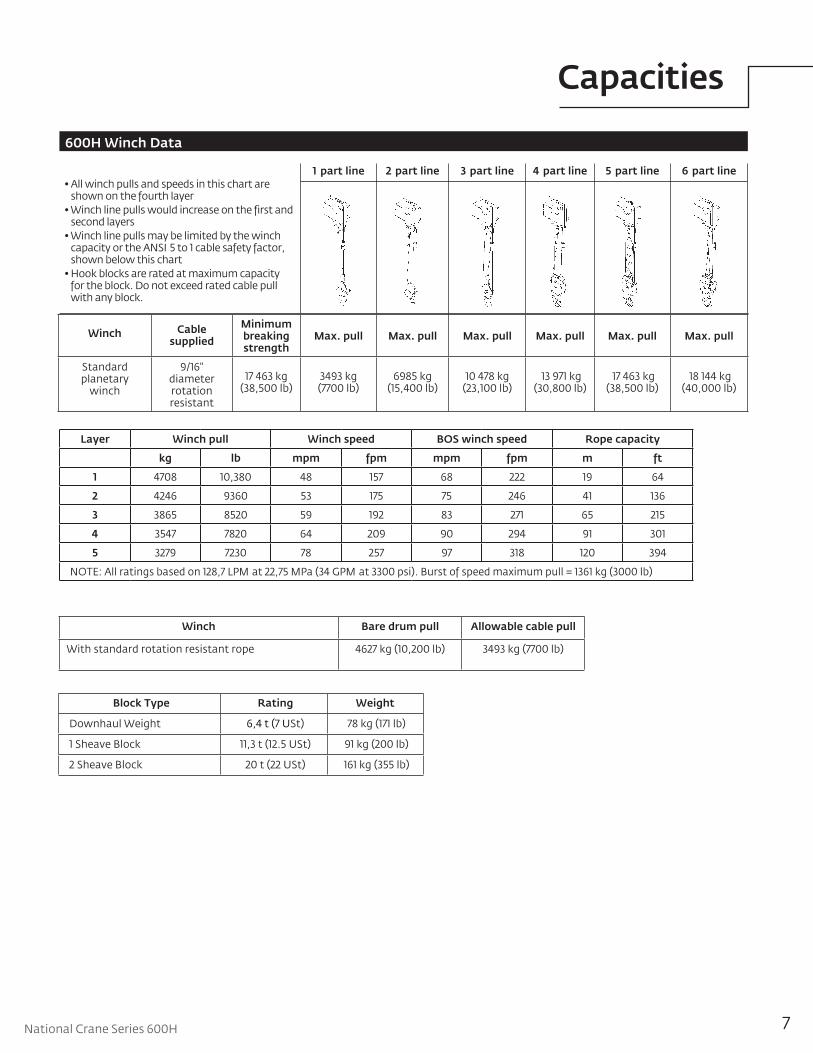
• All winch pulls and speeds in this chart are shown on the fourth layer
• Winch line pulls would increase on the first and second layers
• Winch line pulls may be limited by the winch capacity or the ANSI 5 to 1 cable safety factor, shown below this chart
• Hook blocks are rated at maximum capacity for the block. Do not exceed rated cable pull with any block.
Winch Cable supplied
Minimum breaking strength
Max. pull Max. pull Max. pull Max. pull Max. pull Max. pull
Standard planetary
winch
9/16" diameter rotation resistant
17 463 kg (38,500 lb)
3493 kg (7700 lb)
6985 kg (15,400 lb)
10 478 kg (23,100 lb)
13 971 kg (30,800 lb)
17 463 kg (38,500 lb)
18 144 kg (40,000 lb)
1 part line 6 part line3 part line2 part line 5 part line4 part line
Winch Bare drum pull Allowable cable pull
With standard rotation resistant rope 4627 kg (10,200 lb) 3493 kg (7700 lb)
Block Type Rating Weight
Downhaul Weight 6,4 t (7 USt) 78 kg (171 lb)
1 Sheave Block 11,3 t (12.5 USt) 91 kg (200 lb)
2 Sheave Block 20 t (22 USt) 161 kg (355 lb)
Layer Winch pull Winch speed BOS winch speed Rope capacity
kg lb mpm fpm mpm fpm m ft
1 4708 10,380 48 157 68 222 19 64
2 4246 9360 53 175 75 246 41 136
3 3865 8520 59 192 83 271 65 215
4 3547 7820 64 209 90 294 91 301
5 3279 7230 78 257 97 318 120 394
NOTE: All ratings based on 128,7 LPM at 22,75 MPa (34 GPM at 3300 psi). Burst of speed maximum pull = 1361 kg (3000 lb)
8THIS CHART IS ONLY A GUIDE AND SHOULD NOT BE USED TO OPERATE THE CRANE.
The individual crane’s load chart, operating instructions and other instructional plates must be read and understood prior to operating the crane.
Capacities
* Shaded areas are structurally limited capacities.
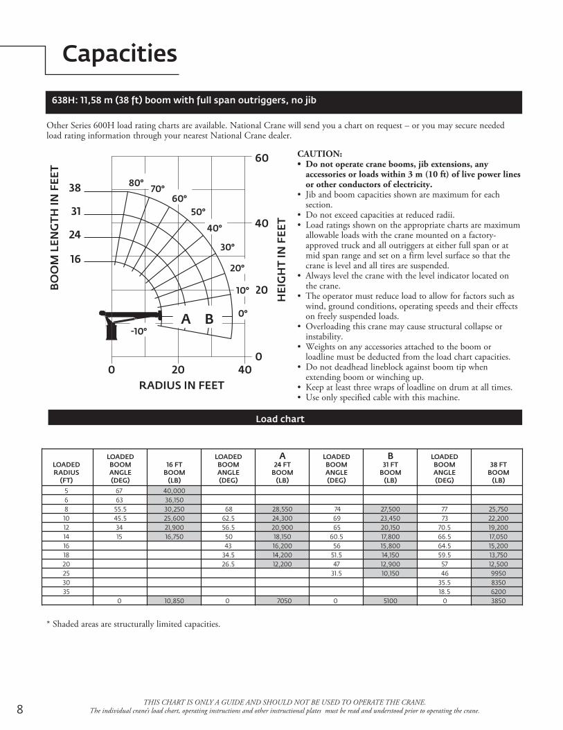
638H: 11,58 m (38 ft) boom with full span outriggers, no jib
Other Series 600H load rating charts are available. National Crane will send you a chart on request – or you may secure needed load rating information through your nearest National Crane dealer.
CAUTION:• Do not operate crane booms, jib extensions, any
accessories or loads within 3 m (10 ft) of live power lines or other conductors of electricity.
• Jib and boom capacities shown are maximum for each section.
• Do not exceed capacities at reduced radii.• Load ratings shown on the appropriate charts are maximum
allowable loads with the crane mounted on a factory-approved truck and all outriggers at either full span or at mid span range and set on a firm level surface so that the crane is level and all tires are suspended.
• Always level the crane with the level indicator located on the crane.
• The operator must reduce load to allow for factors such as wind, ground conditions, operating speeds and their effects on freely suspended loads.
• Overloading this crane may cause structural collapse or instability.
• Weights on any accessories attached to the boom or loadline must be deducted from the load chart capacities.
• Do not deadhead lineblock against boom tip when extending boom or winching up.
• Keep at least three wraps of loadline on drum at all times.• Use only specified cable with this machine.
Load chart
16 FTBOOM
(LB)
LOADEDBOOMANGLE(DEG)
A24 FT
BOOM(LB)
LOADEDBOOMANGLE(DEG)
B31 FT
BOOM(LB)
LOADEDBOOMANGLE(DEG)
38 FTBOOM
(LB)
LOADEDBOOMANGLE(DEG)
LOADEDRADIUS
(FT)
568101214161820253035
40,00036,15030,25025,60021,90016,750
10,850
28,55024,30020,90018,15016,20014,20012,200
7050
27,50023,45020,15017,80015,80014,15012,90010,150
5100
25,75022,20019,20017,05015,20013,75012,5009950835062003850
67 6355.545.5
34 15
0
6862.556.5
50 43
34.526.5
0
74 69 65
60.5 56
51.5 47
31.5
0
77 73
70.566.564.559.5
57 46
35.518.5
0
0 20 400
20
40
60
RADIUS IN FEET
HEI
GH
T IN
FEE
T
38
31
24
16
BO
OM
LEN
GTH
IN F
EET
80°70°
60°50°
40°
30°
20°
10°
0°
-10°A B

9National Crane 600H
Capacities
THIS CHART IS ONLY A GUIDE AND SHOULD NOT BE USED TO OPERATE THE CRANE. The individual crane’s load chart, operating instructions and other instructional plates must be read and understood prior to operating the crane.
RADIUS IN FEET
HEI
GH
T IN
FEE
T
BO
OM
LEN
GTH
IN F
EET
0
10
20
30
40
50
60
70
0 10 20 30 40 50 60
60°
80°70°
50°
40°
30°
16
25
33
41
49
A
B
C
20°
-10°
10°
0°
649H: 15 m (49 ft) boom with full span outriggers, no jib
Other Series 600H load rating charts are available. National Crane will send you a chart on request – or you may secure needed load rating information through your nearest National Crane dealer.
CAUTION:• Do not operate crane booms, jib extensions, any
accessories or loads within 3 m (10 ft) of live power lines or other conductors of electricity.
• Jib and boom capacities shown are maximum for each section.
• Do not exceed capacities at reduced radii.• Load ratings shown on the appropriate charts are
maximum allowable loads with the crane mounted on a factory-approved truck and all outriggers at either full span or at mid span range and set on a firm level surface so that the crane is level and all tires are suspended.
• Always level the crane with the level indicator located on the crane.
• The operator must reduce load to allow for factors such as wind, ground conditions, operating speeds and their effects on freely suspended loads.
• Overloading this crane may cause structural collapse or instability.
• Weights on any accessories attached to the boom or loadline must be deducted from the load chart capacities.
• Do not deadhead lineblock against boom tip when extending boom or winching up.
• Keep at least three wraps of loadline on drum at all times.• Use only specified cable with this machine.
Load chart
16 FTBOOM
(lb)
LOADEDBOOMANGLE(deg)
LOADEDBOOMANGLE(deg)
LOADEDBOOMANGLE(deg)
LOADEDBOOMANGLE(deg)
A25 FT
BOOM(lb)
B33 FT
BOOM(lb)
C41 FT
BOOM(lb)
49 FTBOOM
(lb)
LOADEDBOOMANGLE(deg)
LOADEDRADIUS
(ft)
5
8
10
12
14
16
20
25
30
35
40
45
67
54
44
31.5
8
0
75.5
68
63
57.5
51.5
45
29
0
74
70
66.5
62.5
58
49.5
36
17
0
77.5
74.5
71.5
68.5
65.5
59
50
40
28
0
78
75.5
73
70.5
65
58.5
51
43.5
33.5
19
0
40,000
29,600
24,700
20,400
13,750
10,950
38,100
27,400
23,200
20,200
17,750
15,750
12,100
6350
26,200
22,200
19,250
17,000
15,200
12,500
9850
6950
4350
25,300
21,300
18,450
16,300
14,550
12,050
9800
8050
6450
3200
19,500
17,500
15,000
13,750
11,750
9600
8050
6800
5650
4300
2600
* Shaded areas are structurally limited capacities.

10
Capacities
THIS CHART IS ONLY A GUIDE AND SHOULD NOT BE USED TO OPERATE THE CRANE. The individual crane’s load chart, operating instructions and other instructional plates must be read and understood prior to operating the crane.
* Shaded areas are structurally limited capacities.
660H: 18,3 m (60 ft) boom with full span outriggers, no jib
Other Series 600H load rating charts are available. National Crane will send you a chart on request – or you may secure needed load rating information through your nearest National Crane dealer.
CAUTION:• Do not operate crane booms, jib extensions, any
accessories or loads within 3 m (10 ft) of live power lines or other conductors of electricity.
• Jib and boom capacities shown are maximum for each section.
• Do not exceed capacities at reduced radii.• Load ratings shown on the appropriate charts are maximum
allowable loads with the crane mounted on a factory-approved truck and all outriggers at either full span or at mid span range and set on a firm level surface so that the crane is level and all tires are suspended.
• Always level the crane with the level indicator located on the crane.
• The operator must reduce load to allow for factors such as wind, ground conditions, operating speeds and their effects on freely suspended loads.
• Overloading this crane may cause structural collapse or instability.
• Weights on any accessories attached to the boom or loadline must be deducted from the load chart capacities.
• Do not deadhead lineblock against boom tip when extending boom or winching up.
• Keep at least three wraps of loadline on drum at all times.• Use only specified cable with this machine.
Load chart
24 FTBOOM
(lb)
LOADEDBOOMANGLE(deg)
LOADEDBOOMANGLE(deg)
LOADEDBOOMANGLE(deg)
LOADEDBOOMANGLE(deg)
A33 FT
BOOM(lb)
B42 FT
BOOM(lb)
C51 FT
BOOM(lb)
60 FTBOOM
(lb)
LOADEDBOOMANGLE(deg)
LOADEDRADIUS
(ft)
58101214162025303540455055
75.567.5
62 56
49.5 4324.5
0
74 70 6762.558.549.537.514.5
0
77.5 75 72 69 66 60
51.5 42
30.5
0
7875.5
73 71
6659.5
5345.536.5
25
0
78.576.574.570.565.5
6054.5
48 41 33
21.50
40,00027,20022,80019,65017,15015,15011,150
6150
25,80021,60018,70016,40014,60011,95094006600
3950
25,00020,70017,80015,75014,05011,550935077006100
2700
20,40017,40015,25013,60011,20091007600640053504250
1950
17,15014,95013,20010,85088007400620054004550390030001300
RADIUS IN FEET
HEI
GH
T IN
FEE
T
BO
OM
LEN
GTH
IN F
EET
0
20
40
60
80
100
0 20 40 60 80
-10°
80°70°
60°
50°
40°
30°
20°
10°
0°
51
42
60
24
33
A B C

11National Crane 600H
Capacities
THIS CHART IS ONLY A GUIDE AND SHOULD NOT BE USED TO OPERATE THE CRANE. The individual crane’s load chart, operating instructions and other instructional plates must be read and understood prior to operating the crane.
* Shaded areas are structurally limited capacities.
671H: 21,6 m (71 ft) boom with 13,7 m (45 ft) jib and full span outriggers
Other Series 600H load rating charts are available. National Crane will send you a chart on request – or you may secure needed load rating information through your nearest National Crane dealer.
CAUTION:• Do not operate crane booms, jib extensions, any accessories or
loads within 3 m (10 ft) of live power lines or other conductors of electricity.
• Jib and boom capacities shown are maximum for each section.• Do not exceed capacities at reduced radii.• Load ratings shown on the appropriate charts are maximum allowable
loads with the crane mounted on a factory-approved truck and all outriggers at either full span or at mid span range and set on a firm level surface so that the crane is level and all tires are suspended.
• Always level the crane with the level indicator located on the crane.• The operator must reduce load to allow for factors such as wind, ground
conditions, operating speeds and their effects on freely suspended loads.• Overloading this crane may cause structural collapse or instability.• Weights on any accessories attached to the boom or loadline must be
deducted from the load chart capacities.• Do not deadhead lineblock against boom tip when extending boom or
winching up.• Keep at least three wraps of loadline on drum at all times.• Use only specified cable with this machine.
NOTE:1. Operate with jib by radius when main boom is fully extended. If necessary increase boom angle to maintain loaded radius.2. Operate with jib by boom angle when main boom is not fully extended. Do not exceed rated jib capacities at any reduced boom
lengths.
Load chart
28 FTBOOM
(lb)
LOADEDBOOMANGLE(deg)
LOADEDBOOMANGLE(deg)
LOADEDBOOMANGLE(deg)
LOADEDBOOMANGLE(deg)
LOADEDBOOMANGLE(deg)
A35 FT
BOOM(lb)
B44 FT
BOOM(lb)
C53 FT
BOOM(lb)
D62 FT
BOOM(lb)
71 FTBOOM
(lb)
LOADEDBOOMANGLE(deg)
LOADEDRADIUS
(ft)
581012141620253035404550556065
7770.565.5
61 56
50.5 38
19.5
0
7571.5
6864.560.552.540.5
26
0
78.5 76 7370.567.561.553.545.5
35 20
0
7976.574.5
72 67 61 55 48 40
29.5 14
0
79 77 75 71 66 6155.549.5
43 35
25.5 10
0
7977.5
7469.565.5
61 56 5145.5
3931.5
22
40,00025,55021,00017,90016,00014,90011,3007650
4200
24,75021,00017,95015,55013,70011,10089006600
3100
24,25020,45017,45015,50013,65010,950
8700710058004100
1850
20,10017,150
15,00013,25010,700850070005850490040502450
1150
16,55014,40012,75010,35083006850575048504050340027001500
650
12,45012,45010,050
805066005700480041503550300025001900
25 ft–45 ft JIB FULL SPAN RATED LOADS
25 ftJIB(lb)
LOADEDBOOMANGLE(deg)
44 ftJIB(lb)
LOADEDBOOMANGLE(deg)
LOADEDRADIUS
(ft)253035404550556065707580859095
75.572.5
69 66
62.559.555.5
52 48
43.5 39
33.527.5
76.5 74 72 6966.5
64 6158.5
55 5248.5
45 4136.5
4400390032002750235020001750150013001100900700600
2600245023002100190017001500135012001050900800700600
RADIUS IN FEET
HEI
GH
T IN
FEE
T
BO
OM
LEN
GTH
IN F
EET
0
20
40
60
80
100
120
140
0 20 40 60 80 100 120
534435
6271
-10°
1st Jib 25'
2nd Jib 45'
60°
80°70°
50°
40°36.5°
28 Do notextendjib into
thisarea
27.5°
20°
10°
0°
30°
DCB
A
12
Capacities
THIS CHART IS ONLY A GUIDE AND SHOULD NOT BE USED TO OPERATE THE CRANE. The individual crane’s load chart, operating instructions and other instructional plates must be read and understood prior to operating the crane.
* Shaded areas are structurally limited capacities.
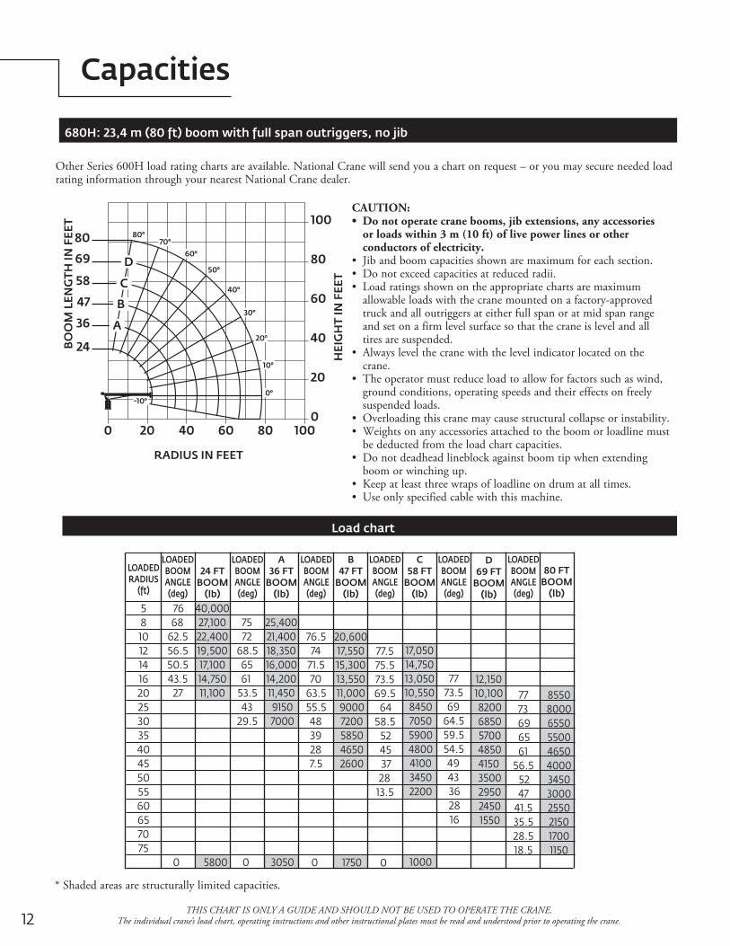
Other Series 600H load rating charts are available. National Crane will send you a chart on request – or you may secure needed load rating information through your nearest National Crane dealer.
CAUTION:• Do not operate crane booms, jib extensions, any accessories
or loads within 3 m (10 ft) of live power lines or other conductors of electricity.
• Jib and boom capacities shown are maximum for each section.• Do not exceed capacities at reduced radii.• Load ratings shown on the appropriate charts are maximum
allowable loads with the crane mounted on a factory-approved truck and all outriggers at either full span or at mid span range and set on a firm level surface so that the crane is level and all tires are suspended.
• Always level the crane with the level indicator located on the crane.
• The operator must reduce load to allow for factors such as wind, ground conditions, operating speeds and their effects on freely suspended loads.
• Overloading this crane may cause structural collapse or instability.• Weights on any accessories attached to the boom or loadline must
be deducted from the load chart capacities.• Do not deadhead lineblock against boom tip when extending
boom or winching up.• Keep at least three wraps of loadline on drum at all times.• Use only specified cable with this machine.
680H: 23,4 m (80 ft) boom with full span outriggers, no jib
Load chart
24 FTBOOM
(lb)
LOADEDBOOMANGLE(deg)
LOADEDBOOMANGLE(deg)
LOADEDBOOMANGLE(deg)
LOADEDBOOMANGLE(deg)
LOADEDBOOMANGLE(deg)
A36 FT
BOOM(lb)
B47 FT
BOOM(lb)
C58 FT
BOOM(lb)
D69 FT
BOOM(lb)
80 FTBOOM
(lb)
LOADEDBOOMANGLE(deg)
LOADEDRADIUS
(ft)
5810121416202530354045505560657075
76 68
62.556.550.543.5
27
0
75 7268.5
65 6153.5
4329.5
0
76.5 74
71.5 70
63.555.5
48 39 28
7.5
0
77.575.573.569.5
6458.5
52 45 37 28
13.5
0
7773.5
6964.559.554.5
49 43 36 28 16
77 73
69 65 6156.5
52 47
41.535.528.518.5
40,00027,10022,40019,50017,10014,75011,100
5800
25,40021,40018,35016,00014,20011,45091507000
3050
20,60017,55015,30013,55011,00090007200585046502600
1750
17,05014,75013,05010,550
8450705059004800410034502200
1000
12,15010,100820068505700485041503500295024501550
855080006550550046504000345030002550215017001150
RADIUS IN FEET
HEI
GH
T IN
FEE
T
BO
OM
LEN
GTH
IN F
EET
0
20
40
60
80
100
0 20 40 60 80 100
36
58
69
80
24
47
-10°
80°70°
60°
50°
40°
30°
20°
10°
0°
A
B
C
D
13National Crane 600H
Capacities
THIS CHART IS ONLY A GUIDE AND SHOULD NOT BE USED TO OPERATE THE CRANE. The individual crane’s load chart, operating instructions and other instructional plates must be read and understood prior to operating the crane.
* Shaded areas are structurally limited capacities.
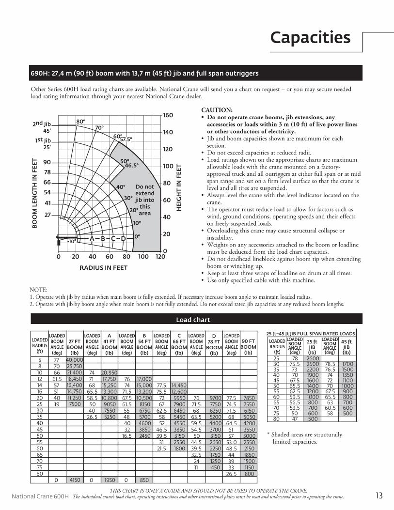
Other Series 600H load rating charts are available. National Crane will send you a chart on request – or you may secure needed load rating information through your nearest National Crane dealer.
CAUTION:• Do not operate crane booms, jib extensions, any
accessories or loads within 3 m (10 ft) of live power lines or other conductors of electricity.
• Jib and boom capacities shown are maximum for each section.
• Do not exceed capacities at reduced radii.• Load ratings shown on the appropriate charts are maximum
allowable loads with the crane mounted on a factory-approved truck and all outriggers at either full span or at mid span range and set on a firm level surface so that the crane is level and all tires are suspended.
• Always level the crane with the level indicator located on the crane.
• The operator must reduce load to allow for factors such as wind, ground conditions, operating speeds and their effects on freely suspended loads.
• Overloading this crane may cause structural collapse or instability.
• Weights on any accessories attached to the boom or loadline must be deducted from the load chart capacities.
• Do not deadhead lineblock against boom tip when extending boom or winching up.
• Keep at least three wraps of loadline on drum at all times.• Use only specified cable with this machine.
690H: 27,4 m (90 ft) boom with 13,7 m (45 ft) jib and full span outriggers
NOTE:1. Operate with jib by radius when main boom is fully extended. If necessary increase boom angle to maintain loaded radius.2. Operate with jib by boom angle when main boom is not fully extended. Do not exceed rated jib capacities at any reduced boom lengths.
Load chart
RADIUS IN FEET
HEI
GH
T IN
FEE
T
BO
OM
LEN
GTH
IN F
EET
70°60°57.5°
50°46.5°
40°
30°
20°
10°
0°-10°
0
20
40
60
80
100
120
140
160
0 20 40 60 80 100 120
27
54
41
66
78
90
1st Jib25'
2nd Jib45'
Do notextendjib into
thisarea
A B C D
80°
27 FTBOOM
(lb)
LOADEDBOOMANGLE(deg)
LOADEDBOOMANGLE(deg)
LOADEDBOOMANGLE(deg)
LOADEDBOOMANGLE(deg)
LOADEDBOOMANGLE(deg)
A41 FT
BOOM(lb)
B54 FT
BOOM(lb)
C66 FT
BOOM(lb)
D78 FT
BOOM(lb)
90 FTBOOM
(lb)
LOADEDBOOMANGLE(deg)
LOADEDRADIUS
(ft)
581012141620253035404550556065707580
77 70 66
61.5 57 51
40 19
0
74 71
6865.558.5
50 40
26.5
0
76 74
71.567.561.5
55 48 40 32
16.5
0
77.575.5
72 6762.5
58 52
46.539.5
3121.5
7671.5
6863.559.554.5
5044.539.532.5
24 11
77.574.571.5
6864.5
61 5753.048.5
44 39 33
26.5
40,00025,75021,40018,45016,40014,75011,2507500
4150
20,95017,75015,25013,30010,800
905075505250
1950
17,00015,00013,20010,500
815067505700460038502450
850
14,45012,600
995079006450545045503850315025501800
97007750625052004400370031502650225017501250450
785075506150505042003550300025502150185015001150800
25 ft–45 ft JIB FULL SPAN RATED LOADS
25 ftJIB(lb)
LOADEDBOOMANGLE(deg)
45 ftJIB(lb)
LOADEDBOOMANGLE(deg)
LOADEDRADIUS
(ft)253035404550556065707580
7875.5
73 70
67.565.562.559.556.553.5
50 47
78.576.5
74 72 70
67.565.5
6360.5
58
26002500220019001600140012001000800700600500
17001500135011001000900800700600500
14
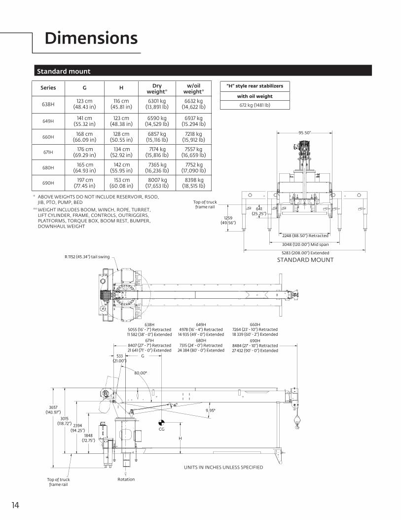
Dimensions
3657(143.97")
3015(118.72") 2394
(94.25")1848
(72.75")
Top of truck frame rail
Rotation
CG
H
9.95°
80.00°
533(21.00")
R 1152 (45.34") tail swing
G
638H5055 (16' - 7") Retracted11 582 (38' - 0") Extended
649H4978 (16' - 4") Retracted
14 935 (49' - 0") Extended
660H7264 (23' - 10") Retracted18 339 (60' - 2") Extended
671H8407 (27' - 7") Retracted21 641 (71' - 0") Extended
680H7315 (24' - 0") Retracted
24 384 (80' - 0") Extended
690H8484 (27' - 10") Retracted27 432 (90' - 0") Extended
UNITS IN INCHES UNLESS SPECIFIED
* ABOVE WEIGHTS DO NOT INCLUDE RESERVOIR, RSOD, JIB, PTO, PUMP, BED
** WEIGHT INCLUDES BOOM, WINCH, ROPE, TURRET, LIFT CYLINDER, FRAME, CONTROLS, OUTRIGGERS, PLATFORMS, TORQUE BOX, BOOM REST, BUMPER, DOWNHAUL WEIGHT
Series G H Dry weight*
w/oil weight*
638H 123 cm (48.43 in)
116 cm (45.81 in)
6301 kg (13,891 lb)
6632 kg (14,622 lb)
649H 141 cm (55.32 in)
123 cm (48.38 in)
6590 kg (14,529 lb)
6937 kg (15.294 lb)
660H 168 cm (66.09 in)
128 cm (50.55 in)
6857 kg (15,116 lb)
7218 kg (15,912 lb)
671H 176 cm (69.29 in)
134 cm (52.92 in)
7174 kg (15,816 lb)
7557 kg (16,659 lb)
680H 165 cm (64.93 in)
142 cm (55.95 in)
7365 kg (16,236 lb)
7752 kg (17,090 lb)
690H 197 cm (77.45 in)
153 cm (60.08 in)
8007 kg (17,653 lb)
8398 kg (18,515 lb)
“H” style rear stabilizers
with oil weight
672 kg (1481 lb)
Standard mount
Top of truck frame rail
1259(49.56")
5283 (208.00") Extended
2248 (88.50") Retracted
3048 (120.00") Mid span
641(25.25")
95.50"
STANDARD MOUNT

National Crane 600H
Accessories
15
Radio Remote Controls – Eliminate the handling and maintenance concerns that accompany cabled remotes. Operate to a range of about 76 m (250 ft), varying with conditions. • RB4R
Heavy-duty Personnel Basket – 544 kg (1200 lb) capacity steel basket with safety loops for two passengers. Gravity leveling 183 cm x 107 cm (72 in x 42 in) platform. Fast attachment and • BSA-1secure locking systems. Load chart must show 1043 kg (2300 lb) minimum to • BSA-R1 (provides rotation)operate this accessory.
Duty Cycle Package – Burst of speed winch (BOS) control option, hydraulic oil cooler (OC), • DCPKGand self-contained radiator system with electric fan.
Single Front Outrigger – Center front stabilizer with a 25 in vertical stroke • SFO
Bulkhead-steel • BHSD
Boom mounted hose reelWith control valve and hydraulic hoses • CRH
Spanish-Language Danger Decals, • SDD
Spanish Operators’ Manuals • SOM

©2014 ManitowocForm No. 600H PGPart No. 600H / 2M / 0314 www.manitowoccranes.com
This document is non-contractual. Constant improvement and engineering progress
Regional offices
ChinaShanghai, China Tel: +86 21 6457 0066Fax: +86 21 6457 4955
Greater Asia-Pacific Singapore Tel: +65 6264 1188 Fax: +65 6862 4040
Europe, Middle East, Africa Dardilly, France Tel: +33 (0)4 72 18 20 20 Fax: +33 (0)4 72 18 20 00
Americas Manitowoc, Wisconsin, USA Tel: +1 920 684 6621 Fax: +1 920 683 6277
Shady Grove, Pennsylvania, USA Tel: +1 717 597 8121 Fax: +1 717 597 4062
Regional headquarters
Manitowoc Cranes
ChinaBeijingChengduGuangzhouXian
Greater Asia-PacificAustraliaBrisbaneMelbourneSydneyIndiaChennaiDelhiHyderabadPuneKoreaSeoulPhilippinesMakati CitySingapore
FactoriesBrazilPasso FundoChinaTaiAnZhangjiagangFranceCharlieuMoulinsGermanyWilhelmshavenIndiaPuneItalyNiella TanaroPortugalBaltarFânzeresUSAManitowoc Port WashingtonShady Grove
AmericasBrazilAlphavilleMexicoMonterreyChileSantiago
Europe, Middle East, AfricaFranceBaudemontCergyDecinesGermanyLangenfeldItalyLainateNetherlandsBredaPolandWarsawPortugalBaltarRussiaMoscowSouth AfricaJohannesburgU.A.E.DubaiU.K.Buckingham