national & international best practices manual pulp ...s3. · pdf file3 “making...
TRANSCRIPT
July 2009
“Make Indian Pulp & Paper Industry World Class”
Volume 2
National & International Pulp & Paper Industry
Best Practices Manual
About CII
About CII-Godrej GBC
About IPMA
The Confederation of Indian Industry (CII) works to create and sustain an environment conducive to the growth of industry in India, partnering industry and government alike through advisory and consultative processes.
CII is a non-government, not-for-profit, industry led and industry managed organisation, playing a proactive role in India's development process. Founded over 113 years ago, it is India's premier business association, with a direct membership of over 7500 organisations from the private as well as public sectors, including SMEs and MNCs, and an indirect membership of over 83,000 companies from around 380 national and regional sectoral associations.
CII catalyses change by working closely with government on policy issues, enhancing efficiency, competitiveness and expanding business opportunities for industry through a range of specialised services and global linkages. It also provides a platform for sectoral consensus building and networking. Major emphasis is laid on projecting a positive image of business, assisting industry to identify and execute corporate citizenship programmes. Partnerships with over 120 NGOs across the country carry forward our initiatives in integrated and inclusive development, which include health, education, livelihood, diversity management, skill development and water, to name a few.
Complementing this vision, CII's theme "India@75: The Emerging Agenda", reflects its aspirational role to facilitate the acceleration in India's transformation into an economically vital, technologically innovative, socially and ethically vibrant global leader by year 2022.
With 64 offices in India, 9 overseas in Australia, Austria, China, France, Germany, Japan, Singapore, UK, USA and institutional partnerships with 211 counterpart organisations in 87 countries, CII serves as a reference point for Indian industry and the international business community.
CII – Sohrabji Godrej Green Business Centre (CII – Godrej GBC), a division of Confederation of Indian Industry (CII) is India's premier developmental institution, offering advisory services to the industry on environmental aspects and works in the areas of Green Buildings, Energy Efficiency, Water Management, Renewable Energy, Green Business Incubation and Climate Change activities.
The Centre sensitises key stakeholders to embrace green practices and facilitates market transformation, paving way for India to become one of the global leaders in green businesses by 2015.
Indian Paper Manufacturers Association (IPMA) has emerged as a national level organisation and is an apex Association provides a broad based common platform to project Industry's view and to articulate its strategy to cater to the growing need and global vision of the Paper Industry. Large Paper Mills from private and public sector with a product mix of all varieties of Paper (Writing, Printing, Packaging, Speciality, Paper boards and Newsprint) located in all regions and using conventional fibre such as wood and bamboo and also unconventional raw materials like bagasse, recycled paper, etc. comprise the Membership of IPMA in a broad spectrum. The Association is registered with the Registrar of Societies, Government of NCT of Delhi.
IPMA strives to promote, protect and improve trade, commerce and Industry in general, with a focus on Industry connected with Paper in particular.
For more details, kindly contact
Survey No 64, Kothaguda Near HITEC City, Hyderabad - 500 084
Tel: +91 40 23112971-73 Fax: +91 40 23112837www.greenbusinesscentre.org

National & International Best Practices - Pulp & Paper Industry
2
Disclaimer
© 2009, Confederation of Indian Industry
All rights reserved. No part of this publication may be reproduced, stored in retrieval system, or transmitted, in any form or by
any means electronic, mechanical, photocopying, recording or otherwise, without the prior written permission from CII-
Sohrabji Godrej Green Business Centre, Hyderabad.
While every care has been taken in compiling this Manual, neither CII-Godrej-GBC nor Indian Paper Manufactures Association
(IPMA) accepts any claim for compensation, if any entry is wrong, abbreviated, omitted or inserted incorrectly either as to the
wording space or position in the manual.
The Manual is only an attempt to create awareness on energy conservation and sharing of best practices being adopted in
Indian and international Paper industry.
Published by Confederation of Indian Industry
CII – Sohrabji Godrej Green Business Centre
Survey # 64, Kothaguda Post, R R District, Hyderabad - 500 084, India.
3
“Making Indian Pulp & Paper Industry World Class”
FOREWORD
The paper industry in India is more than a century old. At present there are over 600 paper
mills in the country manufacturing industrial grades, cultural grades and other specialty papers.
The domestic paper sector is expected to grow at 6.6%, which is higher than the growth rate
globally. With the Indian economy on a solid growth path and the share of services sector in
GDP rising every year, the Indian paper industry holds a huge potential for growth. At present
per capita consumption of paper in India is low at 7.2 kg as compared to 42 kg in China and
350 kg in developed countries, however, the Indian paper industry is poised to grow from
present annual production levels of 9 million tones to 13.95 million tons in 2015-16.
Increasing literacy levels and current lower per capita consumption are compelling reasons to believe that the current
rate of growth would continue for a long period.
Most of the Indian paper mills are in existence for a long time and hence present technologies fall in a wide spectrum
ranging from oldest to the most modern. The paper industry in India is fast adapting state-of-art technologies to reduce
its production cost and to upgrade the technology to meet the international standards. The industry is also fast adapting
ecologically sustainable practices.
CII-Godrej GBC has a vision of making India a Global Leader in Green Business by 2015. To fulfill the vision, the
Centre has adopted several focus areas viz. Green Buildings, Energy Efficiency, Renewable Energy, Environment
& Recycling, Water management and Climate change activities in India.
To advance energy efficiency in the industry, the Centre through the exclusive Energy Efficiency Council facilitates
industries adopt best operational practices and thus become World Class Energy Efficient units.
We strongly believe that, to achieve the vision, it is necessary to demonstrate and achieve leadership status in each sector.
We are now working towards creating “Islands of Excellence” in select sectors, including Pulp and Paper sector.
The organizing of the yearly event Papertech and this manual are efforts in this direction.
I would like to express my gratitude to all the CEOs of the various Pulp & Paper mills in the country for their contributions,
guidance and support in shaping this initiative.
My congratulations to Mr K S Kasi Viswanathan, Chairman, Working group on ‘Make Indian Pulp & Paper Industry
World Class’ and all the members of the core working group for their efforts and contributions.
I am sure that this best practices manual would go a long way in facilitating quicker adoption of best practices in Indian
Pulp and Paper industry.
Chairman, Energy efficiency Council, CII – Godrej GBC

National & International Best Practices - Pulp & Paper Industry
4
5
“Making Indian Pulp & Paper Industry World Class”
PREFACE
The paper industry provides the basic input for most service sectors such as education, print
media and packaging. With the rapid growth of the economy in the past few years, India is
undergoing structural changes with greater urbanization, rise in disposable incomes leading
to higher demand for high-end paper and hygiene paper products. As a result, there is a shift
in demand from low-value paper products to the high-value segment. Further, a spurt in direct
mailers and print media is creating an even greater demand for newsprint.
Buoyed by the growth prospects, companies in the paper industry are in the midst of massive
capacity expansion. According to CMIE data, the value of all the projects, which have eitherbeen announced or are currently under implementation, is around Rs 9,000 crore. Most of
these are newsprint, writing and printing paper projects. Most domestic paper companies are
already operating at 80-90% of their capacities. Since demand is expected to remain robust, the expanded capacities
are unlikely to lead to a glut situation in the industry.
With the increasing Globalization, the Indian paper industry is now looking into all ways and means of making itself
more competitive. This has necessitated Indian paper industry to closely look at Efficient Global players operating outside
India and elevate itself to International level in terms of Efficiency and Technology. The problems of the industry are
being continuously addressed at many forums and macro level policy decisions are under consideration to make its
operations competitive and sustainable.
The World Class Energy Efficiency initiative of CII – Sohrabji Godrej Green Business Centre is one such forum to enhance
competitiveness and also focus on energy efficiency, good environmental performance, Global best practices andtechnology upgrades. The objective of this initiative, with respect to the paper sector is to facilitate in developing at least
three world class Pulp and Paper mills in the country by the year 2010.
This initiative is driven by a core working group with participation from Paper Mills, consultants and equipment suppliers.
As it was with the “National Best Practices Manual – Pulp & Paper Industry”, the objective of this manual is to act as a
catalyst to promote activities in Indian Pulp & Paper Plants towards continual improvement in the performance ofindividual units and thereby move towards “Making Indian Pulp and Paper Industry World Class”.
The future road map of the World Class Energy Efficiency initiative in the Pulp and Paper sector envisages Implementationof the National and International identified best practices in the Indian mills, and bridge the gap between the performances
of large and the small Paper mills in India.
I take this opportunity to thank Mr Pradeep Dhobale, Chairman Energy Efficiency Council, CII - Godrej GBC for hisunstinted support, CEOs of various Paper Mills for their encouragement and the core working group members for their
untiring efforts, which has made this manual a reality.
K S Kasi Viswanathan
Chairman, Working Group on ‘Make Indian Pulp & Paper industry World Class’ and Deputy Managing Director, Seshasayee Paper & Boards Limited

National & International Best Practices - Pulp & Paper Industry
6
7
“Making Indian Pulp & Paper Industry World Class”
CONTENTS
S.NO. Name Page No.
1 Executive Summary 9
2 How to use this Manual 13
Part 1: International Best Practices (European Paper Mills)
3 Summary of Learnings from the visit to European Paper Mills 17
4 Details of European Paper Mills visited
4.1 UPM - Kymmene Wisaforest Pulp And Paper Mill 29
4.2 Stora Enso Imatra Mill 50
4.3 Sunila Mill 54
4.4 M-Real Kyro Mill 57
4.6 Stora Enso, Stracel Mill 61
Part 2: Best Practices implemented in Indian Pulp & Paper Mills
5 List of Best Practices Implemented in Indian Pulp & Paper Mills 71
6 Description of the best practices implemented in Indian Pulp & Paper Mills 73
7 Action Plan & Conclusion 131
8 Annexures
Annexure - A : List of Europeon paper mission attendees 133
Annexure - B : List of Best Practices covered in Volume - I 135

National & International Best Practices - Pulp & Paper Industry
8
9
“Making Indian Pulp & Paper Industry World Class”
EXECUTIVE SUMMARY
Paper industry in India is the 15th largest paper industry in the world. It provides employment to nearly 1.5 million
people and contributes Rs 25 billion to the government’s revenue. The government regards the paper industry as
one of the 35 high priority industries of the country.
In 1951, there were 17 paper mills, and today there are about 515 units engaged in the manufacture of paper and
paperboards and newsprint in India. The pulp & paper industries in India have been categorized into large-scale
and small-scale. Those paper industries, which have capacity above 24,000 tonnes per annum are designated as
large-scale paper industries. India is self-sufficient in manufacture of most varieties of paper and paperboards.
Import is confined only to certain specialty papers. To meet part of its raw material needs the industry has to rely on
imported wood pulp and waste paper.
Growth of paper industry in India has been constrained due to high cost of production caused by inadequate
availability and high cost of raw materials, power cost and concentration of mills in one particular area. Government
has taken several policy measures to remove the bottlenecks of availability of raw materials and infrastructure
development. For example, to overcome short supply of raw materials, duty on pulp and waste paper and wood
logs/chips has been reduced. However, the aspect of higher production cost needs to be tackled by the sector as a
whole by increased cooperation in terms of sharing of best practices and moving towards cleaner production.
The CII - Sohrabji Godrej Green Business Center (CII-Godrej GBC) under the leadership of
Mr. Jamshyd Godrej, Chairman, CII Godrej GBC and Managing Director, Godrej & Boyce has adopted the
vision of “Facilitating India to become a global leader in green business (environment) by 2015”.
Towards this objective, the Energy Efficiency Council of CII-Godrej GBC under the chairmanship of
Mr. Pradeep Dhobale, Divisional Chief Executive, ITC Ltd, PSPD has undertaken the development of
“World Class Energy Efficient Units” in energy intensive sectors, such as Cement, Power Plant and Pulp
& Paper Industry.
The Paper sector initiative through a project titled “Make Indian Pulp & Paper Industry world class” is guided by a
working group chaired by Mr. K S Kasi Viswanathan, Deputy Managing Director, Seshasayee Paper & Boards
Limited (SPB), Pallipalayam.
The activities were initiated in a CEO meet organized in conjunction with Paper Tech 2007 at Hyderabad, a national
conference jointly done by CII-Godrej GBC and Indian Paper Manufactures Association (IPMA). The CEO’s meet
was attended by 19 CEO’s representing all the major Pulp and Paper Manufactures in the country.
The CEO’s discussed and endorsed the following action plan to be taken up for developing World Class Energy
Efficient Paper plants in the country.
National & International Best Practices - Pulp & Paper Industry
10
Core working group:
A core working group was formulated with participation for Paper Mills, consultants and equipment supplier. The
Paper Industry is sub divided into three groups namely Wood, Agro and Recycled fibre group. These groups visited
different paper mills, perceived to be doing well in terms of energy, water and environmental management, and
identified best practices followed in those mills.
Inter plant visits for sharing and identify best practices (during August 2007 – February 2009)
The working group visited some of the Indian Pulp and Paper Industries in order to identify the best practices. The
companies to be selected are identified based on a questionnaire circulated to the above mentioned companies.
The plants visited by the working group are:
1. APPM, Rajahmundry
2. Bilt, Bhigwan Unit
3. Delta Paper Mills Ltd., Vendra
4. Hindustan Newsprint Ltd., Kottayam
5. ITC – PSPD, Bhadrachalam
6. JKPM, Rayagada
7. Naini Tissues Limited, Kashipur
8. Rama Newsprints and Paper Ltd.
9. Shreyans Industries Ltd. (Ahmedgarh unit & Shree Rishab Paper)
10. TamilNadu Newsprint & Papers Ltd., Kagithapuram

11
“Making Indian Pulp & Paper Industry World Class”
About 6 to 10 working group members have visited each of the above mentioned plants which had resulted in a
great learning experience both for the host plant and the working group members. The members of the working
group are mostly Paper Manufactures, Equipment suppliers and Consultants.
The out come of the working group plant visits is identification of 37 best practices from the Indian Pulp and Paper
Industry.
Development of “National Best Practices Manual”
The previous edition of this manual, namely “National Best Practices manual – Pulp & Paper Industry”, was developed
based on the leanings of the working group during the visits to individual plants. The information collected was
collated in to a document which had been widely circulated through out Indian Pulp and Paper Industry.
It was envisaged that the manual would benefit both the participating and the non participating companies. This
would also initiate the process of sharing best practices among pulp and paper Industry.
During Papertech 2008, the “National Best Practices Manual - Pulp & paper Industry” was released on June 27,
2008 at Hyderabad. This manual was widely received and appreciated. The list of best practicies covered in the
manual is enclosed as Annexure - B.
Second CEOs meet 27th June 2008
The CEOs of major Indian pulp & paper mills met again on 27th June 2008 on the morning of first day of Papertech
2008 and reviewed the status of activities of the working group.
The next steps in the process of “Making Indian Pulp & Paper Industry World Class” were envisaged to be focused towards:
� Implementation of the best practices by participating plants
� Studying best practices in overseas installations
� Development of International Best Practices Manual
� Implementation of the international best practices
� Make at least three Indian paper mills world class in three years (by 2010)
In line with this, the core working group met at Chennai subsequently to decide on which mills abroad should be
visited to identify international best practices.
After much deliberation, the core working group came to a conclusion that Scandinavian countries and China have
paper mills that are considered to be the best in a portion of an integrated pulp & paper plant. As a first step, the
Scandinavian countries were visited for identifying international best practices in Pulp & paper industry focusing on
energy, water and environmental management.
With the help of technology suppliers Andritz, GL&V and Metso, the working group has visited the following mills
during the five day visit between 13 - 17 October 2008. The list of Europeon paper mission attendees is enclosed
National & International Best Practices - Pulp & Paper Industry
12
CII thanks the host companies Andritz Oy, GL&V and Metso, for their excellent hospitality provided to the European
mission attendees. This European paper mill mission was conducted by CII, in association with IPMA (Indian Paper
Manufacturers Association). The visit to the Chinese paper mills was postponed in view of the recent economic
downturn.
Development of “National & International Best Practices Manual”
The development of this manual, namely “National & International Best Practices Manual - Pulp & paper
Industry”, contains two parts. While the National best practices were collated from what some of the Indian mills
have done differently in the recent past, the International portion of the manual was developed based on the
learning’s of the working group during the visits to European Paper mills. As with the previous edition of the best
practices manual, the information collected is intended to be collated in to a document that could be widely
circulated in the Indian Pulp and Paper Industry.
This manual is released on July 2, 2009 in the inaugural function of the seminar Papertech 2009 conducted jointly
by CII and IPMA at CII – Sohrabji Godrej Green Business Centre, Hyderabad. In Papertech 2009, together with
sharing of best practices from the Indian Pulp & Paper mills, bringing in more international experiences in the form
of case studies and technological advancements was the focus. Thus the occasion of release of the manual can be
considered apt with its intent of the manual.
S.No. Mill Visited Host Activity / summary
1 UPM Kymenne Wisaforest mill Andritz • Visited Recovery Island of the mill
2 Stora Enso Imatra mill Andritz • Visited pulp mill of the plant for both
soft wood and hardwood streams
3 Sunila mill Andritz • Visited the Wood yard
4 M-real kyro mill GL&V • Visited the Effluent treatment plant
5 Stora Enso, Stracel mill Metso • Visited Paper machine section

13
“Making Indian Pulp & Paper Industry World Class”
HOW TO USE THIS MANUAL
The objective of this manual is to act as a catalyst to promote activities in Indian Pulp & Paper Plants towards
continuously improving the performance of individual units and there by achieving world class levels (with thrust
on energy, water & environmental management).
� To set a clear goal for improving the performance and move towards the world class standards, the best
practices adopted in some Indian Pulp & Paper Plants have been included in this manual as part of “Best
practices from Indian Pulp & Paper Industry”
� The description of the best practices identified during the European paper mills visit by the working group
forms the first part of this manual. The details of the state of the art technologies from the international
paper plants have also been included
� These best practices may be considered for implementation after suitably fine tuning to meet the requirements
of individual units
� Suitable latest technologies may be considered for implementation in existing and future Pulp & Paper
Plants for achieving the world class energy efficiency. Further investigation needs to done for the suitability
of these technologies for Indian conditions
� The collated best operating parameters and the best practices identified from various plants need not
necessarily be the ultimate solution. It is possible to achieve even better energy efficiency and develop
better operation and maintenance practices
Therefore, Indian Pulp & Paper Plants should view this manual positively and utilize the opportunity to improve the
performance and “Make Indian Pulp and Paper Industry World Class”.

National & International Best Practices - Pulp & Paper Industry
14
15
“Making Indian Pulp & Paper Industry World Class”
Part 1
International Best Practices
(European Paper Mills)

National & International Best Practices - Pulp & Paper Industry
16
17
“Making Indian Pulp & Paper Industry World Class”
Summary of Learnings from the visit to European Paper Mills
The following is the summary of the discussion held amongst the attendees of the European paper mill mission on
the final day of the visit of the European paper mills. The discussion goes, more or less, as description of an ideal
integrated pulp and paper plant which has all the latest technologies and best practices implemented in it.
(The list of Europeon paper mission attendees is enclosed in Annexure - A)
Wood Yard
Wood yard also popularly known as ‘chipper house’ is generally a neglected area in the Indian Pulp & paper
industry in terms of energy conservation. Being the initial phase of the paper making process, chipping and screening
system has a significant bearing on the quality of the final product (paper or board or pulp).
1. Installation of disc chippers with a good wood feeding system
� Stora Enso Sunilla mill (visited in the second half of 14th October 2008 near Turku, Finland) has disc
chippers installed and is operating since 1990
� Out of the two popularly known chippers of drum type and disc type, many Indian mills have been
traditionally using drum chippers
� Disc chippers have several advantages over drum chippers owing to the cutting action as against
crushing action in the drum chippers
� Lower power consumption
� Less sliver formation
� More consistent size of chips
� Less dust formation
� While installing disc chippers, care needs to be taken so that the feeding system should be able to
handle thin wood logs. Amongst the Indian Pulp & Paper mills, TNPL & ITC- Bhadrachalam have
installed disc chippers and are operating successfully since quite some time. This aspect was covered
as a best practice in the previous edition of the best practices manual for Pulp & Paper Industry
� Also, the effectiveness of feeding system is the major aspect which governs the parameter of
specific power consumption in a disc chipper. This is because the design of the feeding system
governs the effective load time of the chipper and thus alters the overall specific power consumption
with a component of non useful power consumption, namely no-load power
National & International Best Practices - Pulp & Paper Industry
18
2. Installation of thickness screening systems after size screens.
� Thickness screening system is installed at Sunila mill and the cooking system does not have any
screening for knots
� Screening of chips according to thickness is beneficial
in more than one way
� Uniform cooking of the entire digester feed
� Avoids generation of uncooked chips
� Minimizes knots formation
� Yield of digestion system increases
� Overall quality of chips improves
� Thickness screening of chips is not practiced in any of the Indian Pulp & Paper mills. ITC – PSPD,
Bhadrachalam unit has a very good wood yard system but for this aspect in its wood yard.
3. Log washing and Chip washing systems
� Log washing and chips washing helps in chips conditioning during storage
� This also reduces the amount of silica content (surface silica and the sand particles picked up). This
in-turn helps in reduction in scale formation in the evaporator section.
4. Mechanical conveying of chips instead of pneumatic conveying
� Mechanical conveying consumed lesser power than pneumatic conveying
� Mechanical systems are easier to maintain and are known for trouble free operation
� Also, the damage to the chips is reduced to a great extent with Mechanical conveying systems
� Modern types of mechanical conveying systems include
� Belt conveyors – traditionally used in the Indian pulp & paper mills at other locations
� Cleated belt conveyors: These belt conveyors can have higher angle of elevation upto 70
degrees from the horizontal axis.
� Pipe conveyors: Though a little expensive than the belt conveyors, these systems can transport
chips in an enclosed pipe.
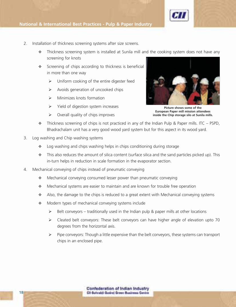
Picture shows some of theEuropean Paper mill mission attendees
inside the Chip storage silo at Sunila mills.
19
“Making Indian Pulp & Paper Industry World Class”
Cooking Section:
Reference mill visited as part of this mission (Stora Enso Imatra mill) have previous generation continuous and super
batch digesters. Some of the Indian Paper mills have advanced digester systems. While the continuos digestor is
installed at APPM, the super batch digesters are installed at TNPL and ITC; also being installed at Westcoast and
Century Pulp & Paper.
With mixed hard wood feed stock available to the Indian Paper mills, both these cooking systems are
suitable and acceptable. This can be inferred from the choices made by the Indian paper mills mentioned above,
for their cooking system. In general, a continuous digester has an edge over the super batch digesters in terms of
energy consumption and consistency in quality of pulp. As a thumb rule, a continuous digester is considered
economical with capacities going above 500 TPD and super batch digester systems are considered economically
apt for capacities less than 500 TPD.
Rapid Displacement Heating (RDH) cooking and super batch are good proven technologies by themselves, and as
discovered by the mission attendees during the course of discussions, GL&V has combined the advantages of these
technologies and have come up with a more energy efficient cooking process called “Dual C”. They claim that this
will have a reduction of 15% in steam consumption for the Dual C over that of the RDH. Moreover, GL&V can also
offer upgradation of the existing RDH systems to the Dual C cooking system and achieve a benefit of 10 - 15%
reduction in steam consumption in the cooking process.
Fibre Line (for Wood based systems)
The configuration of a good fibre line would consist of washing and screening section (W&S) followed by a two
stage Oxygen De-Lignification (ODL) and then followed by a an Elemental Chlorine Free (ECF) bleaching section.
� Even though ECF bleaching is considered best by EPA, there is a need to introduce Ozone into the bleaching
sequence for environmental reasons. These are available from Andritz and Metso as ZeTrack or Lite-ECF
� The treatment of pulp with Ozone in the beaching section should be done at as high consistency as possible
using presses (about 40%)
In case of press based washing and bleaching systems, hard stock screening should be before washing and for
washer based bleaching and washing systems, the screening is to be located after ODL. This practice increases yield
of the fibre line.
� While press based systems are offered by Metso, the washer based systems are offered by Andritz. Andritz
is now offering press based systems, GL&V offers for either systems based on capacities
Indian Pulp mills have fibre lines of the latest technology in the market. For example ITC- Bhadrachalam and TNPL
have recently commissioned their new fibre lines, while Westcoast and Century Pulp & Paper are in the process of
procuring and installing advanced fibre lines.
� ITC is the third mill in the world to use ozone in the bleaching process and it also enjoys the distinction of
having the largest ozone generator in the world
National & International Best Practices - Pulp & Paper Industry
20
� The performance of the fibreline using ozone has been quite satisfactory in terms of pulp quality and
reduction in variable production cost
� The fibre line of the reference mill visited (Stora Enso Imatra mill) turned out to be inferior in technology and
environmental impacts when compared with the best fibre line available in India
However, the following are the identified best practices in the Fibre Line section.
� Selective delignification in the fiberline with two stage Oxygen DeLignification
� Reducing ClO2 consumption by combining the bleaching sequence with the mixture of Ozone and oxygen
� Centri-cleaners are not recommended to be installed in the fibreline. However, this idea is considered
debatable by some
� Recommended bleaching sequence is as follows.
� First stage : DHD or D0 or Z/D
� Second stage : EO
� Third Stage : D1
� Fourth stage : D/P (only for special cases requiring high brightness)
Recovery Island & Power Block
Evaporator section
Some of the Indian pulp & paper mills have very good evaporator section – ITC- Bhadrachalam, TNPL, APPM,
Abishek paper mills, to name a few. But these Pulp and Paper mills do not have some technologies that if installed
would take them to new heights in environmental friendliness. Some of the technologies listed below are installed
at the visited reference mill (Wisaforest mill at Peitersaari).
� Potassium and Chloride removal system from the black liquor is essential to minimize tube corrosion at
higher operating temperatures of recovery boiler
� Though this by itself does not give any benefit in terms of energy or environment, Potassium and
chloride removal system will enable to install and operate the recovery boilers at 105 ata and 510
deg C
� Installing high pressure recovery boiler (105 ata) increases the cogeneration opportunity in an
integrated paper plant
� The condensate collected of the vapours generated in the evaporator (and used for their latent heat in the
subsequent effects), commonly known as evaporator foul condensate, needs undergo Condensate stripping.
Though this is not energy friendly, it has significant benefits in terms of recycling of water and reduction in
effluent load
21
“Making Indian Pulp & Paper Industry World Class”
Recovery Boiler:
The visited reference mill of UPM Kymmene Wisaforest has an impressive recovery island. One prominent feature of
the recovery section of UPM Kymmene Wisaforest mill is that of a high pressure boiler (105 ata and 510 oC). The
group found out that the boiler was operated with steam generation at only 100 bar and 460oC. The reason for
such an operational practice was attributed to the fact that the Wisaforest mill did not have the Potassium and /or
Chloride removal system. This has made a significant difference in the power generation of the plant.
On detailed analysis of the system, combined with the assorted experiences of the participants, the following
points were identified.
� Potassium and / or chloride removal system form the black liquor is a pre-requisite for the operation of the
recovery boiler at high pressures and temperatures (105 ata and 510 oC)
� Also, while designing the recovery boilers for operating conditions of 105 ata and 510oC, it has to be
ensured that composite tubes are used in the construction of the main tubes for heat transfer. This will
enable Non condensable gasses (NCGs) from the pulp mill and the evaporator sections to be fired into the
recovery boiler. Though the NCGs do not have very high calorific values, this practice will help fight the
conventional odor problems of the pulp mill and the evaporators. These have to be handled in the recovery
boiler below the secondary level
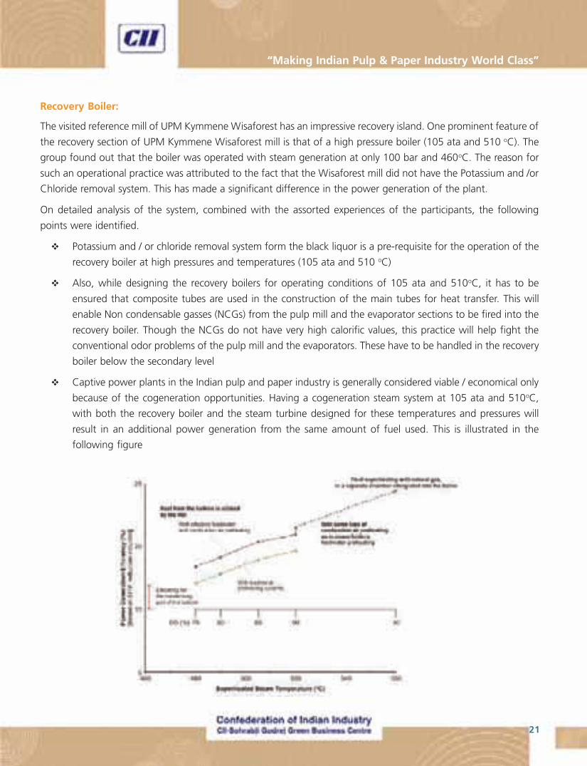
� Captive power plants in the Indian pulp and paper industry is generally considered viable / economical only
because of the cogeneration opportunities. Having a cogeneration steam system at 105 ata and 510oC,
with both the recovery boiler and the steam turbine designed for these temperatures and pressures will
result in an additional power generation from the same amount of fuel used. This is illustrated in the
following figure
National & International Best Practices - Pulp & Paper Industry
22
Power block:
Many of the major Indian Pulp & Paper mills (integrated) have their own captive power plant as it enables them to
have an economical electrical power and thermal (by steam) energy by the means of cogeneration. Unlike the
European counter parts, the Indian mills have a power boiler in addition to the recovery boiler. This is mostly due to
the economics of power generation and import in India and that in Europe.
Even in the case of power boilers in the Indian paper mills, having systems of higher pressure and temperatures is
beneficial in terms of energy economy. Thus the following are the points noted in this regard.
� Must go for 105 bars and 510 oC and unify with the recovery boilers steam system
� CFBC boilers are to be preferred for higher efficiency and higher flexibility in term of variety of fuels fired.
� This type of boilers are available even for small capacities but is generally considered more economical
than AFBC boilers in ranges of steam capacities of above 50 – 75 TPH
� Recognizing these benefits, all the new boilers that BILT has procured are of CFBC type
� Having a condensing cum extraction turbine will provide greater operational flexibility in terms of balancing
between the steam and electrical energy requirement of the plant. This will also keep the electrical power
import from the power grid to a minimum
� With more than one outlet for the turbine, it is advisable to have one outlet with internal control and
another outlet with external control. Having both outlets with internal control will definitely reduce the
isentropic efficiency of the turbine generator system
� A condensate polishing unit is essential in reducing the quantity of De- Mineralized (DM) water added for
boiler feed water make up
a. The condensate polishing unit has to be coupled with a heat recovery unit so that the condensate
enters the polishing unit at less than 40oC. (The resins available in the market for a condensate
polishing unit are capable of performing only at or less than 40oC.)
Caustisizing:
� Green Liquor filtration – use of pressure filtration
� Precoat filter for dregs filtration
� Multidisc pressure filter for WL delivers better quality of WL in terms of clarity
� Multidisc vacuum filter for lime filter with lime dryness greater than 70% will result in a lower energy
consumption for re-burning of lime. Other benefits include higher quality of WL and higher efficiency of
chemical recovery cycle
� ITC- Bhadrachalam and TNPL have these technologies implemented (except for GL side)
23
“Making Indian Pulp & Paper Industry World Class”
Lime Kiln:
� Installation of Rotary lime Kiln is necessary as the lime sludge is now categorized as hazardous waste
� Traditionally, HFO or Furnace oil is used as fuel for the rotary lime kilns. There is increased need to look at
alternative fuels for this
� Tall oil can be derived only with Softwood as feed stock. With hard wood based raw materials in
the Indian scenario, this options is not feasible
� Gassification technology of wood or other agri-residues is available but is not commercially established
and so is considered theoretical
� Producer gas derived from Coal can substitute 60- 70% of HFO fired in the Lime Kiln. Some mills in
India have installed Producer gas plants – OPM, BILT – Yamunanagar, CPP-Lalkuan
� Presence of Silica in the lime sludge is considered as an environmental problem. Lime mud purging from the
cycle is generally practiced. But with lime sludge now being classified as hazardous waste, ways and means
of silica removal from the lime mud needs to be explored
� This problem is not normally found in the case of European paper mills because of the their increased
use of softwood
� Alternately, two stage caustisizing will also help counter this problem especially if bamboo is used
as the raw material
Paper Machine
The participants of the Paper mission to European paper mills have visited Stracel mill on the French side of the
border with Germany. Apparently, the mill has no captive power generation but meets its steam requirements by
generation in the waster heat recovery boilers. (What are these boilers? What is the heat source?)
Suiting to the Indian conditions of having mixed hard wood feed stock, paper machines of a maximum speed of
1300 mpm (meters per minute) are recommended for economical design. At higher speeds the head box and
former section become expensive.
Pulp Sheeting Machine:
Unlike the European paper mills, most of the Indian mills have the pulping making system and the paper machine
located in the same compound. A pulp sheeting machine is not very relevant to the Indian pulp & paper industry
owing to the low number of such machines installed in the country.
Finishing House:
This section is not dealt with in detail as the group felt, this portion is tailor made to suite the requirements of an
individual mill and the extent of automation the mill feels necessary.
National & International Best Practices - Pulp & Paper Industry
24
Water Treatment system:
Though depending on the quality of water available to a Paper mill, the water treatment facility is designed, the
following sequence of operations can be considered during a new installation or while modifying /upgrading.
Step 1: Primary clarifier /clari-flocculator
Step 2: Filtration (pressure sand filter or gravity sand filter)
Step 3: (Only for Boiler feed water, EOP presses & washers and high purity needs)
Option 1 : DM plant (DeMiniralization)
Option 2 : DM + UF (DeMineralisation + Ultra Filtration)
Option 3 : RO + UF (Reverse Osmosis + Ultra Filtration)
The option to be chosen at step 3 depends on the quality of water required.
Effluent Treatment Plant:
The strategy to adopt for effective effluent handling is by reducing the effluent at source. For example, hot effluent
from Chlorine-di-Oxide stage of bleaching (Do or DHT) has to pass through a heat exchanger to recover heat from
that portion of the effluent. Also, this will eliminate the need to have a cooling tower for the effluent before going
to the ETP
In general for an ETP, the following series of steps are recommended.
� Primary Clarifier (Aimed at eliminating suspended solids)
� A best practice of the secondary treatment is diffused aeration
� Various methods area available for this system. Out of these Durofloc is considered most effective.
Examples of these include MBR, MBBR technologies.
� Clarifier
� There is a great need for the use of a Tertiary treatment in the ETPs of the Indian paper mills to fight the
color problem of the effluent
� Generally not practiced in the Indian paper mills
� To be based on micro flotation to reduce color and enable recycling of most of the effluent water.
� As a first step, the water consumption in the paper mill has to be reduced to quantity of effluent
generated. This in turn will make the installation of the tertiary treatment system less arduous
� The sludge collected from the primary & secondary clarifiers and the tertiary treatment, has to be used of its
calorific value and generate steam
� In the Wisaforest paper mill, the sludge thus collected was added to the black liquor at the third
effect of the evaporator and is fired in the recovery boiler as part of black liquor
25
“Making Indian Pulp & Paper Industry World Class”
� Considering the Indian scenario of having a power boiler as well, the sludge can be thickened and
sent to a screw press to get the sludge out of it with 50% moisture content. This can be used in the
power boiler to substitute for a little portion of the fuel fired
Miscellaneous observations:
� In the process of selection and operation of pumps and agitators, it is recommended to install equipment of
high energy efficiency rather than the one with lower capital investment. As thumb rule, the capital cost of
a pump or an agitator is only about 3% of the total life cycle cost, while the operation cost (energy cost)
accounts for over 90% share
� Air compressors: For the sake of energy efficiency, a centrifugal compressor is to be preferred over reciprocating
or screw type. Care needs to be taken to ensure complete utilization of the capacity of the centrifugal
compressor. Throttling of suction guide vane or venting of compressed air is not energy efficient operating
practices of a centrifugal compressor. Also, the lowest capacity centrifugal compressor available in the
market is 1000 cfm
� Electrical systems
� Installation of only Energy efficient motors has to be ensured and added as a clause in the failure
replacement policy of a given paper mill
� Intelligent MCCs (Smart digital systems with PLC installed within the MCCs). These are very
economical when looked at the combined cost with DCS systems
� Installation of Switchless Fuses
� It is imperative to have electrical systems with 690 V as the line voltage in the plant. It is proven at BILT,
Bhigwan that this system will lower the distribution loss with an overall loss reduction of 0.8 – 0.9%.
For a new project, this will also lower the installation cost by about 5%. Apart from the voltage
ratings of the circuit breakers, the main distribution transformer has to rated for 11 kV / 690 V

National & International Best Practices - Pulp & Paper Industry
26
� Instrumentation: Foundation field Bus or Profi-bus system has to be preferred
� Wireless communication with digital transmission of data
� No stray voice voltages
� MOC (Material of Construction)
� Causticising : Stainless Steel for Green Liquor & White Liquor handling
� SS for instrument air piping and condensate piping
27
“Making Indian Pulp & Paper Industry World Class”
Details of European Paper Mills visited

National & International Best Practices - Pulp & Paper Industry
28
29
“Making Indian Pulp & Paper Industry World Class”
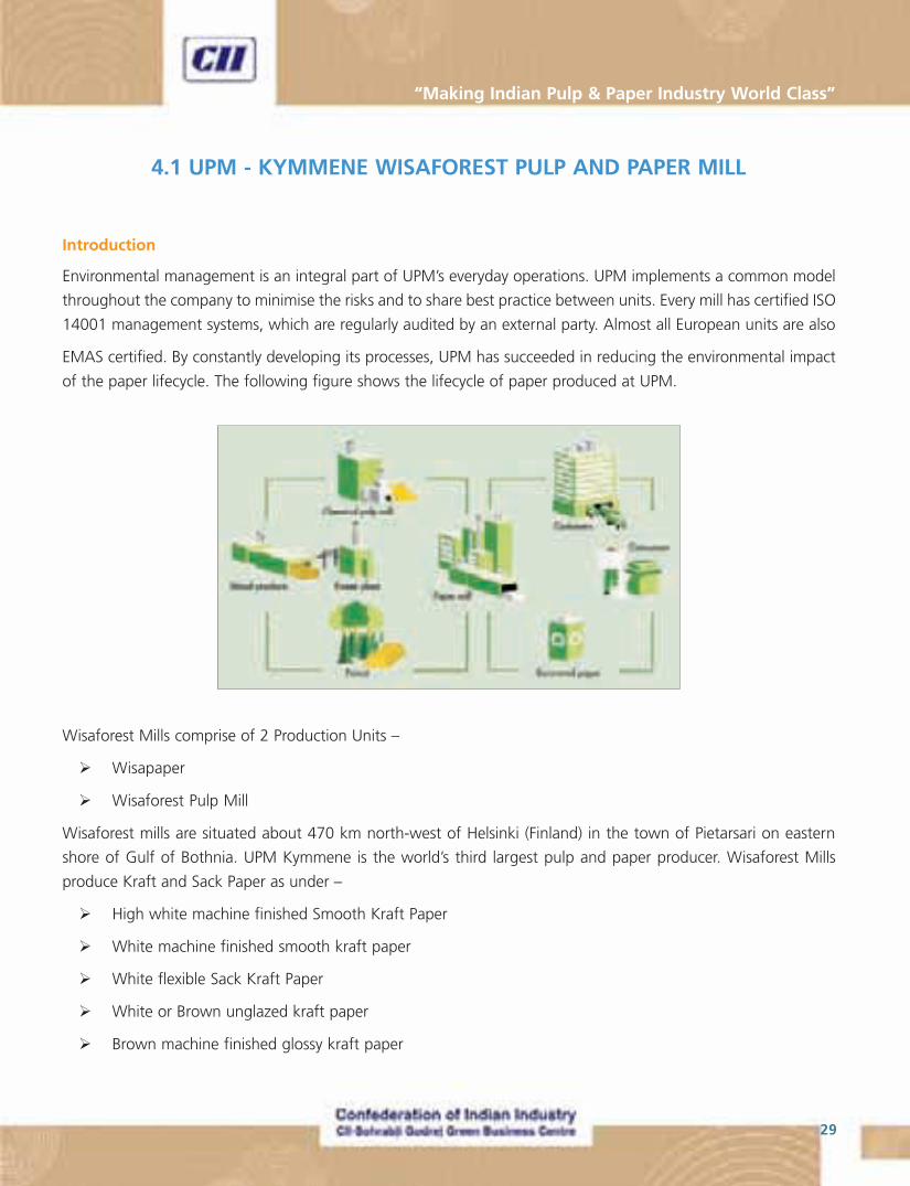
4.1 UPM - KYMMENE WISAFOREST PULP AND PAPER MILL
Introduction
Environmental management is an integral part of UPM’s everyday operations. UPM implements a common model
throughout the company to minimise the risks and to share best practice between units. Every mill has certified ISO
14001 management systems, which are regularly audited by an external party. Almost all European units are also
EMAS certified. By constantly developing its processes, UPM has succeeded in reducing the environmental impact
of the paper lifecycle. The following figure shows the lifecycle of paper produced at UPM.
Wisaforest Mills comprise of 2 Production Units –
� Wisapaper
� Wisaforest Pulp Mill
Wisaforest mills are situated about 470 km north-west of Helsinki (Finland) in the town of Pietarsari on eastern
shore of Gulf of Bothnia. UPM Kymmene is the world’s third largest pulp and paper producer. Wisaforest Mills
produce Kraft and Sack Paper as under –
� High white machine finished Smooth Kraft Paper
� White machine finished smooth kraft paper
� White flexible Sack Kraft Paper
� White or Brown unglazed kraft paper
� Brown machine finished glossy kraft paper
National & International Best Practices - Pulp & Paper Industry
30
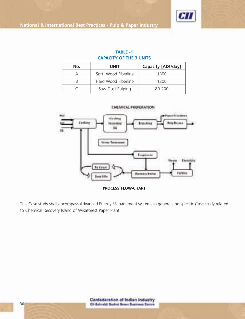
TABLE -1CAPACITY OF THE 3 UNITS
No. UNIT Capacity [ADt/day]
A Soft Wood Fiberline 1300
B Hard Wood Fiberline 1200
C Saw Dust Pulping 80-200
This Case study shall encompass Advanced Energy Management systems in general and specific Case study related
to Chemical Recovery Island of Wisaforest Paper Plant.
PROCESS FLOW-CHART
31
“Making Indian Pulp & Paper Industry World Class”
NEW RECOVERY BLOCK
Background
UPM Kymmene, Finland, entrusted Andritz with the supply of a complete chemical recovery system
for its Wisaforest pulp mill in Pietarsaari, Finland, for a total volume of over 100 MEUR (Million Euro). The system
would the largest chemical recovery system worldwide at that time. The contract encompassed all major processes
of chemical recovery: the evaporation plant, recovery boiler, recausticizing plant and lime reburning kiln.
UPM Kymmene is the world’s third largest pulp and paper producer. For this Pohjolan Voima Oy (PVO), a Finnish
company based at Helsinki, supplied the biggest single-cylinder turbine-generator to be installed in a pulp and
paper mill. With the plant operating at 100% steam generating capacity some of the electricity produced is supplied
to the electricity grid.
Multiple-effect Falling Film Evaporator:
The seven effect evaporator plant was supplied by Andritz and has an evaporation capacity of 1,050 tonnes of
water/Hr; it is said to be the most advanced unit in the world considering the features built in to the system. The
configuration is more like 7.5 effects because the high density unit, which is operated with medium pressure
steam. It can produce heavy liquor at a concentration of 85% dry solids and weak liquor is fed to the evaporator at
14.6% dry solids content. The high concentration end of the process equipment features duplex steel construction
because of high corrosion risk with such a high solids content and high temperatures.
Lamella technology is used in the evaporator units, with internal segregation in effects numbered two to seven.
The evaporation plant also features liquor heat treatment (integrated in effect one), a calcium deactivation unit
(between effects two and three), an integrated stripping unit and methanol liquefaction system. The technology
based on Lamella is the most commonly used for high dry solids black liquor evaporation, with testing done upto
92%. This is one reason why Wisaforest decided to go as high as 85% as their design dry solids.
The secondary condensates are split into four fractions instead of the conventional three and are used in the fibre
line and recausticizing process as wash or dilution water.
The lamella evaporator operates on the falling film principle. The heating surface consists of stainless steel elements.
Steam for evaporation condenses inside the elements, and delivers the condensing energy through the element
wall. Black liquor is fed to the bottom of the unit. A small circulation pump lifts the liquor to the top part. The liquor
distribution system delivers black liquor evenly on the outer surfaces of all elements. Due to gravity, the liquor flows
down as a film. Heat from condensing steam induces boiling of the liquor. Secondary vapor is separated immediately
after generation from the black liquor and flows to the surrounding space. A profile type mist eliminator at the top
of the evaporator ensures the purity of secondary vapor.
National & International Best Practices - Pulp & Paper Industry
32
Resistance against scaling
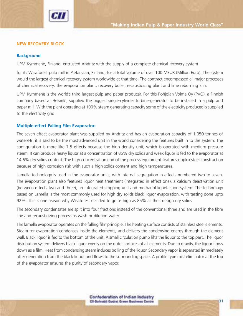
One major advantage of lamella heating surface is its inherent resistance to scaling. Uniform liquor distribution on
the heating elements and continuous redistribution of the liquor by the dimpled shape of the surface ensure
completely wetted heating surface and eliminate local over-concentrations. The scale peels off due to the dimpled
shape thus providing a self-cleaning effect in some difficult cases
Condensate segregation
With an Andritz evaporator, the plant is able to generate clean condensates reusable
within the pulping process. Clean condensates are the result of an evaporator
design that minimizes dry solids carry over and optimally divides the condensates
in different fractions. The unique construction of the heating element with bottom
vapor inlet and internal stripping effect enables cleanest condensates of any multi-
effect kraft liquor evaporator – clean enough to be used in bleach plant.
The giant evaporation plant at UPM Kymmene’s Wisaforest mill in Pietarsaari is the
first one in the world having a steam condensate optimization to four fractions
using integrated condensate segregation allowing most effective re-utilization of
the condensates in mill processes.
Chemical Recovery Boiler:
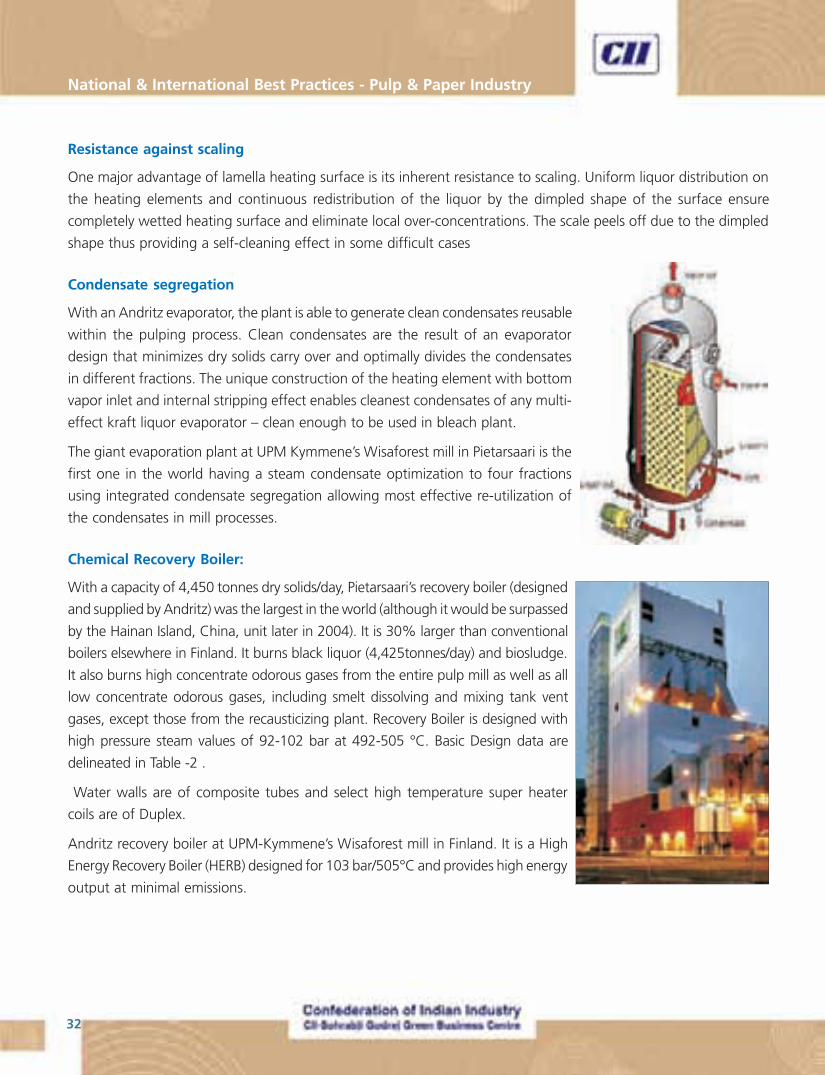
With a capacity of 4,450 tonnes dry solids/day, Pietarsaari’s recovery boiler (designed
and supplied by Andritz) was the largest in the world (although it would be surpassed
by the Hainan Island, China, unit later in 2004). It is 30% larger than conventional
boilers elsewhere in Finland. It burns black liquor (4,425tonnes/day) and biosludge.
It also burns high concentrate odorous gases from the entire pulp mill as well as all
low concentrate odorous gases, including smelt dissolving and mixing tank vent
gases, except those from the recausticizing plant. Recovery Boiler is designed with
high pressure steam values of 92-102 bar at 492-505 °C. Basic Design data are
delineated in Table -2 .
Water walls are of composite tubes and select high temperature super heater
coils are of Duplex.
Andritz recovery boiler at UPM-Kymmene’s Wisaforest mill in Finland. It is a High
Energy Recovery Boiler (HERB) designed for 103 bar/505°C and provides high energy
output at minimal emissions.
33
“Making Indian Pulp & Paper Industry World Class”
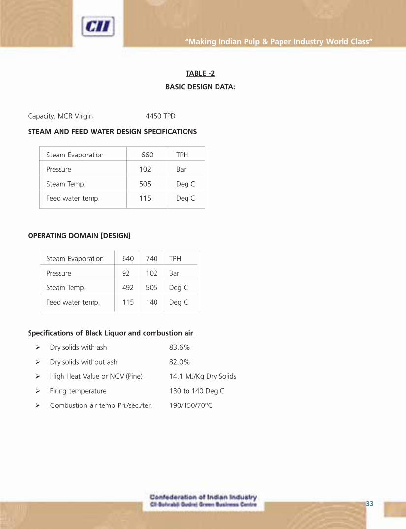
TABLE -2
BASIC DESIGN DATA:
Capacity, MCR Virgin 4450 TPD
STEAM AND FEED WATER DESIGN SPECIFICATIONS
Steam Evaporation 660 TPH
Pressure 102 Bar
Steam Temp. 505 Deg C
Feed water temp. 115 Deg C
OPERATING DOMAIN [DESIGN]
Steam Evaporation 640 740 TPH
Pressure 92 102 Bar
Steam Temp. 492 505 Deg C
Feed water temp. 115 140 Deg C
Specifications of Black Liquor and combustion air
� Dry solids with ash 83.6%
� Dry solids without ash 82.0%
� High Heat Value or NCV (Pine) 14.1 MJ/Kg Dry Solids
� Firing temperature 130 to 140 Deg C
� Combustion air temp Pri./sec./ter. 190/150/70°C
National & International Best Practices - Pulp & Paper Industry
34
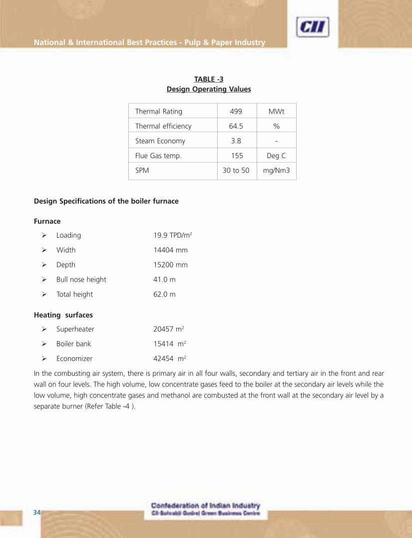
TABLE -3Design Operating Values
Design Specifications of the boiler furnace
Furnace
� Loading 19.9 TPD/m2
� Width 14404 mm
� Depth 15200 mm
� Bull nose height 41.0 m
� Total height 62.0 m
Heating surfaces
� Superheater 20457 m2
� Boiler bank 15414 m2
� Economizer 42454 m2
In the combusting air system, there is primary air in all four walls, secondary and tertiary air in the front and rear
wall on four levels. The high volume, low concentrate gases feed to the boiler at the secondary air levels while the
low volume, high concentrate gases and methanol are combusted at the front wall at the secondary air level by a
separate burner (Refer Table -4 ).
Thermal Rating 499 MWt
Thermal efficiency 64.5 %
Steam Economy 3.8 -
Flue Gas temp. 155 Deg C
SPM 30 to 50 mg/Nm3
35
“Making Indian Pulp & Paper Industry World Class”
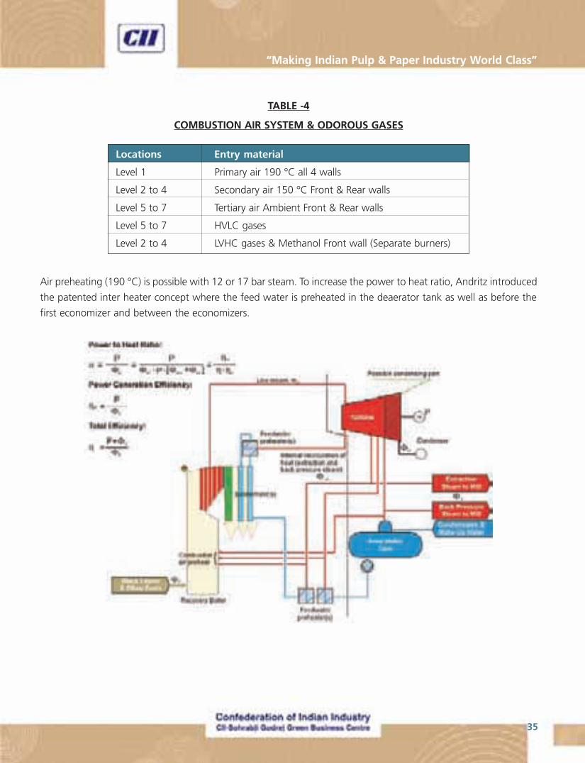
TABLE -4
COMBUSTION AIR SYSTEM & ODOROUS GASES
Air preheating (190 °C) is possible with 12 or 17 bar steam. To increase the power to heat ratio, Andritz introduced
the patented inter heater concept where the feed water is preheated in the deaerator tank as well as before the
first economizer and between the economizers.
Locations Entry material
Level 1 Primary air 190 °C all 4 walls
Level 2 to 4 Secondary air 150 °C Front & Rear walls
Level 5 to 7 Tertiary air Ambient Front & Rear walls
Level 5 to 7 HVLC gases
Level 2 to 4 LVHC gases & Methanol Front wall (Separate burners)
National & International Best Practices - Pulp & Paper Industry
36
The Deaerator Operating Temperature is 128 Deg C. Feed water, containing mostly process return condensates is
at 85 Deg C entering the deaerator. LP steam consumption is at a low of 12.9 kg/s, which is about 6% of Steam
generation from the boiler.
Soot blowing steam is sourced from the turbo generator at the required pressure to increase the power input. This
aspect had been detailed in a later section.
In early June the mill was running at 92 bar and 490 °C. Preheating the feed air up to 190 °C provides a higher
power to heat ratio that allows the mill to produce more electricity from the same amount of heat put into the
boiler.
With the conventional fuel available (i.e., the black liquor from eucalyptus pulping), the recovery boiler can produce
only 185 kg/s of steam.
Biological sludge (to the extent of around 40 TPD) along with Non-condensable gases (NCG) is being burnt in the
boiler.
The boiler bank is so big that two soot blower columns had to be installed. Special materials were used in the
construction of the super heater because of the high temperatures and pressures.
The mill does not segregate its liquor so the recovery boiler will burn black liquor sourced from both soft wood and
hardwood liquor. At times, Pietarsaari pulps softwood in both its continuous and batch processes so there will be
only softwood liquor. This means higher solids content because the yield is lower. As noted, eucalyptus has higher
yields so fewer solids are send to the recovery boiler.
The electrostatic precipitator has three chambers with four fields in each. It was made big so the mill could keep the
flue gas temperature elevated.
Despite the large increase in production, effluent emissions have fallen. The new environmental limits for flue gas
dust particles are 50 mg/Nm3 for the recovery boiler and 60mg/Nm3 for the lime kiln.
Low temperature heat recovery scheme, in the style of feed/combustion air heating with flue gas heater located
immediately after ESP.
Operation at highest level:
The plant team operated the plant at the highest levels of temperature and pressure for few months at Steam
outlet temperature of 520 to 525 °C, as also at 87% (Dry solids) black liquor solids concentration. For fear of
chloride corrosion of super heater tubes, experiment was discontinued of operating at the highest design steam
pressure and BLS concentration.
During the team visit to the mill during October 2008, performance of the Recovery Boiler in operation was studied
(Fig. 3). The select operational performance data are elicited in Table -5.
37
“Making Indian Pulp & Paper Industry World Class”
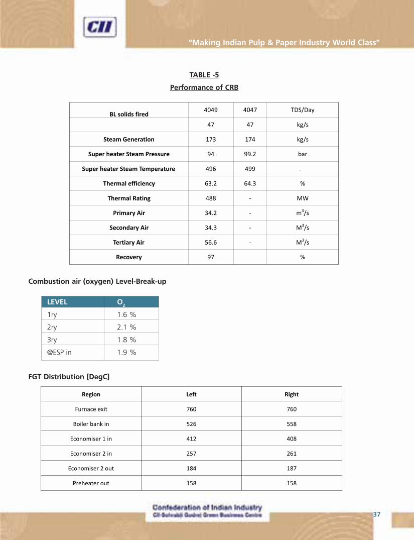
TABLE -5
Performance of CRB
Combustion air (oxygen) Level-Break-up
LEVEL O2
1ry 1.6 %
2ry 2.1 %
3ry 1.8 %
@ESP in 1.9 %
FGT Distribution [DegC]

National & International Best Practices - Pulp & Paper Industry
38
Fig. 4. Steam Turbine Flow Chart
STEAM TURBINE GENERATOR
The steam turbine, a single-cylinder backpressure machine with an electrical output of 150MW is equipped with a
multiple shifting non automatic extraction. It is operated with main steam at 100 bar / 505 °C.
Steam Turbine Generator design specifications are delineated in Table –6
TABLE-6
STG DESIGN SPECIFICATIONS
Siemens turbine is a centre-admission, extraction back-pressure design with a power generation capacity of 143MW,
with extraction pressure at three levels viz., 11 bar, 7 bar and 3 bar ( Fig.4). Best power generation efficiency is
obtained with a steam flow range of 175-200 kg/s, corresponding to a power generation of 100-120MW.
39
“Making Indian Pulp & Paper Industry World Class”
ROTARY LIME KILN
The lime kiln has a capacity of 750 tonnes/day of burnt lime. The kiln itself is 135m long with a diameter of 4.75m.
The modern LMD design features sectorial cooling and burns tall oil, furnace oil, methanol and turpentine. However,
the goal is to burn mostly tall oil.
Electrowatt-Ekono supplied the 8 tonnes/Hr (192tonnes/day) HDS tall oil plant while polar gas supplied the CO2
neutralization unit (to reduce sulphur). Following neutralization, there is final acidification with sulphuric acid and
crude tall oil separation.
Fuzzy logic control
Temperature profile optimization along kiln length.
� Energy efficiency enhancement
� Kiln availability increase
� Reburned lime quality enhancement
� Energy reduction
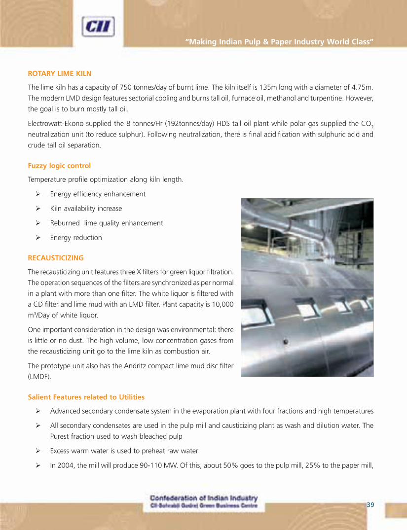
RECAUSTICIZING
The recausticizing unit features three X filters for green liquor filtration.
The operation sequences of the filters are synchronized as per normal
in a plant with more than one filter. The white liquor is filtered with
a CD filter and lime mud with an LMD filter. Plant capacity is 10,000
m3/Day of white liquor.
One important consideration in the design was environmental: there
is little or no dust. The high volume, low concentration gases from
the recausticizing unit go to the lime kiln as combustion air.
The prototype unit also has the Andritz compact lime mud disc filter
(LMDF).
Salient Features related to Utilities
� Advanced secondary condensate system in the evaporation plant with four fractions and high temperatures
� All secondary condensates are used in the pulp mill and causticizing plant as wash and dilution water. The
Purest fraction used to wash bleached pulp
� Excess warm water is used to preheat raw water
� In 2004, the mill will produce 90-110 MW. Of this, about 50% goes to the pulp mill, 25% to the paper mill,
National & International Best Practices - Pulp & Paper Industry
40
Case Study No. 1
MULTILEVEL COMBUSTION IN THE RECOVERY BOILER
Improving air systems
To achieve solid operation and low emissions the recovery boiler air system needs to be properly designed. Air
system development continues and has been continuing as long as recovery boilers have existed. As soon as the
target set for the air system has been met new targets are given. Currently the new air systems have achieved low
NOx, but are still working on lowering fouling. The Table 7 visualizes the development of air systems.
Table 7: Development of air systems.
The first generation air system in the 1940’s and 1950’s consisted of a two level arrangement; primary air for
maintaining the reduction zone and secondary air below the liquor guns for final oxidation. The recovery boiler size
was 100 - 300 TDS/day (Total Dissolved Solids per day) and black liquor concentration 45 – 55 %. Frequently to
sustain combustion auxiliary fuel needed to be fired. Primary air was 60 – 70 % of total air with secondary the rest.
In all levels openings were small and design velocities were 40 – 45 m/s. Both air levels were operated at 150oC.
Liquor gun or guns were oscillating. Main problems were high carryover, plugging and low reduction. But the
function, combustion of black liquor, could be filled.
The second generation air system targeted high reduction. In 1954 CE moved their secondary air from about 1 m
below the liquor guns to about 2 m above them. The air ratios and temperatures remained the same, but to
increase mixing 50 m/s secondary air velocities were used. CE changed their frontwall / backwall secondary to
tangential firing at that time. In tangential air system the air nozzles are in the furnace corners. The preferred
method is to create a swirl of almost the total furnace width. In large units the swirl caused left and right imbalances.
This kind of air system with increased dry solids managed to increase lower furnace temperatures and achieve
reasonable reduction. B&W had already adopted the three-level air feeding by then.
Air system Main target But also should
1st generation Stable burning of black liquor
2nd generation high reduction Burn liquor
3rd generation decrease sulfur emissions Burn black liquor, high reduction
4th generation low NOx Burn black liquor, high reduction and low sulfur emission
5th generation decrease superheater and Burn black liquor, high reduction, low emissions
boiler bank fouling
41
“Making Indian Pulp & Paper Industry World Class”
Third generation air system was the three level air. In Europe the use of three levels of air feeding with primary and
secondary below the liquor guns started about 1980. At the same time stationary firing gained ground. Use of
about 50 % secondary seemed to give hot and stable lower furnace. Higher black liquor solids 65 – 70 % started
to be in use. Hotter lower furnace and improved reduction were reported. With three level air and higher dry solids
the sulfur emissions could be kept in place.
Fourth generation air systems are the multilevel air and the vertical air. As the feed of black liquor dry solids to the
recovery boiler have increased, achieving low sulfur emissions is not anymore the target of the air system. Instead
low NOx and low carryover are the new targets.
Multilevel air
The three-level air system was a significant improvement, but better results were required. Use of CFD models
offered a new insight of air system workings. The first to develop a new air system was Kvaerner (Tampella) with
their 1990 multilevel secondary air in Kemi, Finland, which was later adapted to a string of large recovery boilers.
Kvaerner also patented the four level air system, where additional air level is added above the tertiary air level. This
enables significant NOx reduction.
Vertical air
The idea in vertical air concept is to turn traditional vertical mixing to horizontal mixing. Closely spaced jets will
form a flat plane. In traditional boilers this plane has been formed by secondary air. By placing the planes to 2/3 or
3/4 arrangement improved mixing results. Vertical air has a potential to reduce NOx as staging air helps in decreasing
emissions. In vertical air mixing, primary air supply is arranged conventionally. Rest of the air ports are placed on
interlacing 2/3 or 3/4 arrangement.
The recovery boiler at UPM Kymene Wisaforest mill uses Andritz’s Vertical Air system for efficient burning of black
liquor at very low emissions levels. The emission levels of the boiler is given in table 8.
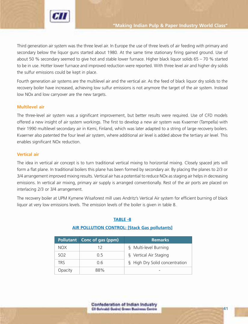
TABLE -8
AIR POLLUTION CONTROL: [Stack Gas pollutants]
Pollutant Conc of gas (ppm) Remarks
NOX 12 § Multi-level Burning
SO2 0.5 § Vertical Air Staging
TRS 0.6 § High Dry Solid concentration
Opacity 88% -
National & International Best Practices - Pulp & Paper Industry
42
The designers of the boiler have done considerable development work to minimize emissions from recovery boilers
(particularly NOx emissions) and to improve the reliability and safety of the boiler. The chemical recovery boiler at
UPM-Kymmene’s Pietarsaari mill included several innovations. The Andritz Vertical Air System™ for the first time
includes a two-level spraying arrangement of black liquor. This will further decrease NOx emissions in the flue gas.
Also, a virtual dynamic simulator was included in the recovery boiler plant delivery. The simulation is so realistic that
operators cannot tell the difference between a simulated operation and the actual process.
Case Study No. 2
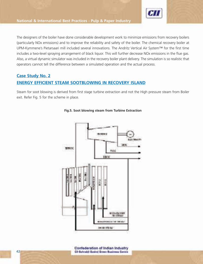
ENERGY EFFICIENT STEAM SOOTBLOWING IN RECOVERY ISLAND
Steam for soot blowing is derived from first stage turbine extraction and not the High pressure steam from Boiler
exit. Refer Fig. 5 for the scheme in place.
Fig.5. Soot blowing steam from Turbine Extraction
43
“Making Indian Pulp & Paper Industry World Class”
The Soot blowing scheme adopted is one of Low pressure (11 bar) steam blowing, whether it is superheater, boiler
bank or economiser zones.
Through the implementation of the above scheme, the power gain is around 1 to 1.1 to 1.3 MW. With daily power
addition of ~ 30,000 units, it is sizable revenue for the plant authorities.
Smart soot blowing for conserving the steam is not gone in for, for fear of likely non-removal of the deposits
especially in the super heater zone and for fear of attendant chloride/potassium corrosion.
Fear of chloride corrosion had also been the reason for not going in for the design operating pressure (105 bar) and
temperature (510 Deg C) and BLS concentration (87 %).
OPERATIONAL GAINS
� High power to steam ratio for recovery boiler and turbo generator
� But for a short Annual shut, there had not been any other outages and the plant team cannot recollect any
forced outage
� Good and easy control of furnace and efficient combustion
� Very high Steam Economy & overall Cycle efficiency
� Gas pollutant emissions of a low order
� State of the art condition monitoring in place
ISSUES
� Electrical Inverter had given minor problem
� Corrosion in APH tubes noted
� Secondary Air Ports burning, because of high temperature, which in turn is due to operation at low loads
(at times)
� Black liquor solid concentration had to be maintained at 83 %, because of fear of Chloride corrosion &
potassium salt deposit on pressure part exterior
National & International Best Practices - Pulp & Paper Industry
44
Case Study No. 3
PIETERSAARI SAW MILL - SAW DUST COOKING
Background
The Saw mill produces about 100,000 m3 of saw dust annually. Earlier practice was to burn the saw dust in the
boiler for steam generation. However with WISA 800 project, UPM decided to produce pulp from saw dust by
cooking.
Conventional saw dust cooking was not preferred since it was rough on the fiber. ANDRITZ had specially developed
the Cooking process to facilitate slow and gentle cooking of fibres to achieve maximum strength and yield.
Trial and test runs were conducted in the ANDTDRITZ Research laboratory for yielding process suitable for Wisaforest.
Design capacity of the installed system is 200 ton/day. Production varies from a minimum of 80 TPD to a maximum
of 200 TPD. Since the process is tailor made for Wisaforest, it is ensured that there is no degradation when the
sawdust pulp is added to the Hardwood pulp. The Sawdust cooking technology is discussed briefly in the following
section.
The mill uses 2.6 million m3/yr of softwood, 73% of which is round wood and the rest chips, and 1.5 m3/yr of
hardwood, 81% of which is round wood, 13% sawdust and 6% chips.
The final piece of the WISA 800 jigsaw was the installation of a new M&D (Andritz) sawdust digester in summer
2004. It will produce 40,000 tonnes/yr from sawdust from UPM’s own sawmills as well as other sawmills in the
area. This sawdust had previously been burnt in the lime kiln after gasification.
The sawdust digester’s capacity is as high as 200 tonnes/day. Following a first washing stage and oxygen
delignification, the pulp will then be conveyed to the hardwood line for further washing and screening. Although
it will use softwood waste, the new digester is considered part of the hardwood line. The mill’s birch pulp will
contain 10% sawdust pulp.
When all is said and done, the mill will be able to produce 450,000 tonnes/yr of softwood pulp and 350,000
tonnes/yr of hardwood. The pulp’s main end use is uncoated and coated printing papers.
Sawdust Cooking Technology
Cooking Process steps
� Impregnation stage performed at low temperature in Digester.
� The Digester finishes the cook
� Pulp washed in DD Washer
The Andritz solutions for the pulping of sawdust include the DownFlow Single-vessel Digester and the M&D
Digester (Messing–Durkee Digester).

45
“Making Indian Pulp & Paper Industry World Class”
Lo-Solids Cooking
Lo-Solids® Cooking is a patented process which makes use of distributed white liquor addition (even alkali profile),
clean filtrate addition, and multiple extraction points to create a “cleaner, lower solids cooking environment.
The Andritz Lo-Solids® cooking solution achieves high pulp strength and optimal properties for bleaching. The Lo-
Solids® digester provides high cooking capacity and washing efficiency with minimal chemical consumption and
low rejects. Significant cooking yield improvements have been measured on hardwood Lo-Solids® Cooking references.
The most common type of Lo-Solids® digester supplied by Andritz has been the single-vessel hydraulic digester.
Having a hydraulically full vessel removes the need to control liquor level, making this type of digester is simple to
operate. As an alternative, the Andritz two-vessel system utilizes an Impregnation Vessel before the Cooking Vessel
to allow time for the cooking liquor to impregnate the chips. The transfer circulation between the vessels helps
to maintain uniform conditions prior to cooking. In some cases, the two-vessel approach can reduce the amount
of necessary cooking circulations within the Cooking Vessel
M&D Digester
In the M&D digesting system retention time, temperature and liquor concentration can be controlled to maximize
pulp quality. Pulp washing in M&D digester systems is accomplished externally with washers such as the Andritz
Pressure Diffuser and Drum Displacer® Washers.
Pressure Diffuser
The Andritz Pressure Diffuser is a diffusion-type washer that is perfectly suited as a brownstock washer in the
blowline of a continuous digester. The continuous digester operating pressure supplies the energy to push the
pulp through the machine without the use of MC pumps.
Pressure Diffuser systems require a very little space for installation and are easily retrofitted into the blowline of
existing digester systems. The Pressure Diffuser has the highest single-stage washing efficiency of any other washer
available
Pressure Thickener Screen
The Andritz Pressure Thickener (PT Screen) series is a family of pressurized, hydraulic thickeners that was designed
as a pre-thickener for the feed to a low consistency Andritz Drum Displacer™ Washer. The PT Screen serves as
the separation of optimal screening consistency from optimal Drum Displacer Washer feed consistency.
Depending on the amount of thickening required, a single PT Screen can handle a range from 200 ADMT/d up to
2000 ADMT/d. The feed consistency of a PT Screen is normally 2.5%–4%, and with a discharged pulp consistency
in the range of 3.5% to 6%.
National & International Best Practices - Pulp & Paper Industry
46
Case Study No. 4
ENERGY EFFICIENCT LIME REBURNING PROCESS
At the Wisaforest pulp mill, the smelt from two recovery boilers is dissolved and diluted with weak liquor and raw
water. The green liquor is fed from the dissolving tank in to the mixing tank where the flow, temperature and
density variations are smoothed out. It is then fed in to the green liquor clarification in order to remove insoluble
materials. After clarification, the green liquor is pumped into two parallel
slakers, and the reburned lime is fed at a controlled rate in to the slakers. The
lime milk continually flows from the slakers into a series of causticizing tanks
with a total retention time of about two to three hours. The white liquor
produced is then clarified by means of pressurized disc filters, and the liquor
is pumped in to the white liquor tanks, while the separated mud is pumped
into storage tanks.
Mud discharged from the storage tanks is pumped into the two parallel precoat
type drum filters. After the filters, the lime mud ( ~ 75% dry solids content)
is conveyed to a screw feeder, which distributes the mud into the flue gas
duct. The fast flowing flue gas carries the mud into an external lime mud
drier (LMD). After separation of preheated mud from the cooled flue gas, the
mud is discharged from the bottom cone of the drier and fed into the cold-
end of kiln.
The rotary lime kiln has a total length of 104 metres, an external diameter of
3.6 metres and an angle of inclination of 2Ú. The design capacity of the kiln
is 500 tonnes of reburned lime per day.
After the LMD cyclone, the flue gas passes through an electrical precipitator
Drum Displacer
The Andritz Drum Displacer® Washer is a high efficiency, high performance pulp washer for brownstock washing,
oxygen delignification and bleaching stages.
The Drum Displacer® Washer can include up to four complete stages of washing on a single washer. This unique
multi-stage feature means that where once multiple washers were necessary, now a single Drum Displacer® Washer
may be sufficient. The DD Washer is the perfect solution for replacing older multiple stage vacuum drum washer
lines.
The Drum Displacer® Washer is manufactured in a variety of sizes, for both low and medium consistency applications
with single unit capacity up to 3500 ADMT/d.
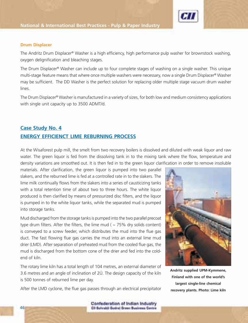
Andritz supplied UPM-Kymmene,
Finland with one of the world’s
largest single-line chemical
recovery plants. Photo: Lime kiln
47
“Making Indian Pulp & Paper Industry World Class”
and a two stage venturi type wet scrubber. The major part of the dust that escapes the cyclone is captured in an
electrostatic precipitator and is fed back into the kiln. Drying and heating of the lime mud continues in the kiln as
the mud powder moves down the gradient of the kiln. The heat from the hot reburned lime leaving the kiln is used
to preheat the secondary combustion air .Primary combustion air which is taken between the stationary hood and
the product coolers, is forced into the kiln together with the fuel.
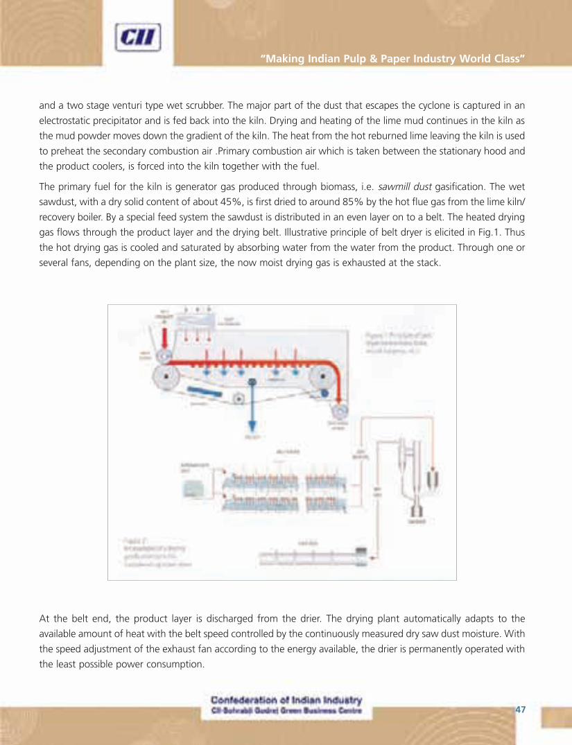
The primary fuel for the kiln is generator gas produced through biomass, i.e. sawmill dust gasification. The wet
sawdust, with a dry solid content of about 45%, is first dried to around 85% by the hot flue gas from the lime kiln/
recovery boiler. By a special feed system the sawdust is distributed in an even layer on to a belt. The heated drying
gas flows through the product layer and the drying belt. Illustrative principle of belt dryer is elicited in Fig.1. Thus
the hot drying gas is cooled and saturated by absorbing water from the water from the product. Through one or
several fans, depending on the plant size, the now moist drying gas is exhausted at the stack.
At the belt end, the product layer is discharged from the drier. The drying plant automatically adapts to the
available amount of heat with the belt speed controlled by the continuously measured dry saw dust moisture. With
the speed adjustment of the exhaust fan according to the energy available, the drier is permanently operated with
the least possible power consumption.
National & International Best Practices - Pulp & Paper Industry
48
The dried sawdust, which has a heat value of around 12 MJ/kg, is fed into the circulating fluidized bed gassifier
(Fig.2), where the volatiles are converted into gas. The generated gas is then led in to the kiln and burnt in the air.
The principal motivation for sawdust burning is the significant reduction in heat energy cost. One important advantage
is that this also reduces the use of non-renewable fossil fuel is reduced, and hence also the overall balance of the
carbon dioxide (CO2) emissions can be reduced by burning renewable biomass. The secondary fuel is heavy fuel oil,
is having sulphur content of 0.9 w%.
The temperature during lime calcination is typically monitored by means of a number of temperature sensors
installed along the length of the kiln. In the Wisaforest mill, the temperature of the flue gas is measured by means
of thermocouple installed next to the external lime mud drier, after the kiln in the flue gas duct and inside the cold-
end of the kiln.
The temperature measurements are, however, more related to the flue gas emissions and heat losses than the lime
quality. The temperature of the product in the lime kiln, which is an essential temperature measure with respect to
lime quality, is measured by two pyrometers. Unfortunately, these temperature readings are exposed to disturbances
e.g by dust formation, and are therefore not suitable for control purpose s. The temperature in the hot-end of the
kiln is also measures by a thermocouple mounted on the front wall of the kiln. In addition to radiation from the lime
bed, the thermometer is also influenced by the fuel mixture, the shape and temperature of the flame, and the
temperature of the incoming secondary burning air.
On an average, sawdust accounts for about 80% of the total heat energy input into the kiln. Heavy fuel oil, which
has a heat value of about 41MJ/kg, is usually burnt in addition to sawdust. It was given to understand that till oil is
also being used as fuel (which needs to be doubly re-confirmed). Frequently, especially during periods with a low
production rate, sawdust is burnt alone. Fuel oil alone is occasionally used, e.g. due to shortage of dried sawdust
or during repairs of the gasifier.
One negative aspect associated with the use of sawdust (common to all bio-fuels) is the inconsistency in the energy
content and problems in regulating the feed rate. Random changes in sawdust quality (ie. In the composition,
moisture, and/or size distribution) or in the actual feed rate result in variations in the heat energy input into the kiln.
As a result, considerable fluctuations in the temperature are a common problem, because of irregular variations in
the energy input and with improper control; which also causes undesired variation in the quality of the lime.
Changes in the fuel mixture, i.e. the ratio between the burning of sawdust and fuel/tall oil, have a tendency to
cause serious disturbances in the process. Improperly managed changes increase the risk of undesired temperature
excursions, which have a detrimental influence on the service life of the refractory bricks. Changes in the fuel
mixture also often induce a short term imbalance between the fuel supply and the flow of the burning air, which
may result in a considerable rise in the flue gas emissions.
49
“Making Indian Pulp & Paper Industry World Class”
Advanced Fuzzy Logic Controls – An Energy Efficient Tool
Fuzzy logic control had successfully been employed for meeting the challenges in temperature control with the
producer gas generated from any of different fuel combinations viz., sawdust and oil, in isolation or as admixture
in varying proportions.
� Energy efficiency enhancement
� Temperature profile optimisation
� Increased availability of the lime kiln
� Reduction in energy consumption
� Flexibility in co-fuel firing; Choice of firing HVLC gases.
� Enhancement of reburned lime quality
Conclusion
Hence with the process scheme as stated above, certainly has substantial mileage in energy conservation had been
achieved in Wisaforest lime kiln centre. This had certainly paved the way for other paper and pulp mills having
rotary lime kilns in place.
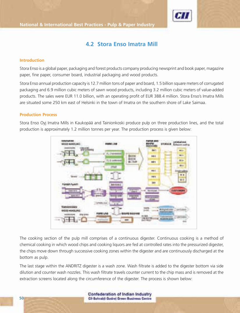
National & International Best Practices - Pulp & Paper Industry
50
4.2 Stora Enso Imatra Mill
Introduction
Stora Enso is a global paper, packaging and forest products company producing newsprint and book paper, magazine
paper, fine paper, consumer board, industrial packaging and wood products.
Stora Enso annual production capacity is 12.7 million tons of paper and board, 1.5 billion square meters of corrugated
packaging and 6.9 million cubic meters of sawn wood products, including 3.2 million cubic meters of value-added
products. The sales were EUR 11.0 billion, with an operating profit of EUR 388.4 million. Stora Enso’s Imatra Mills
are situated some 250 km east of Helsinki in the town of Imatra on the southern shore of Lake Saimaa.
Production Process
Stora Enso Oyj Imatra Mills in Kaukopää and Tainionkoski produce pulp on three production lines, and the total
production is approximately 1.2 million tonnes per year. The production process is given below:
The cooking section of the pulp mill comprises of a continuous digester. Continuous cooking is a method of
chemical cooking in which wood chips and cooking liquors are fed at controlled rates into the pressurized digester,
the chips move down through successive cooking zones within the digester and are continuously discharged at the
bottom as pulp.
The last stage within the ANDRITZ digester is a wash zone. Wash filtrate is added to the digester bottom via side
dilution and counter wash nozzles. This wash filtrate travels counter current to the chip mass and is removed at the
extraction screens located along the circumference of the digester. The process is shown below:
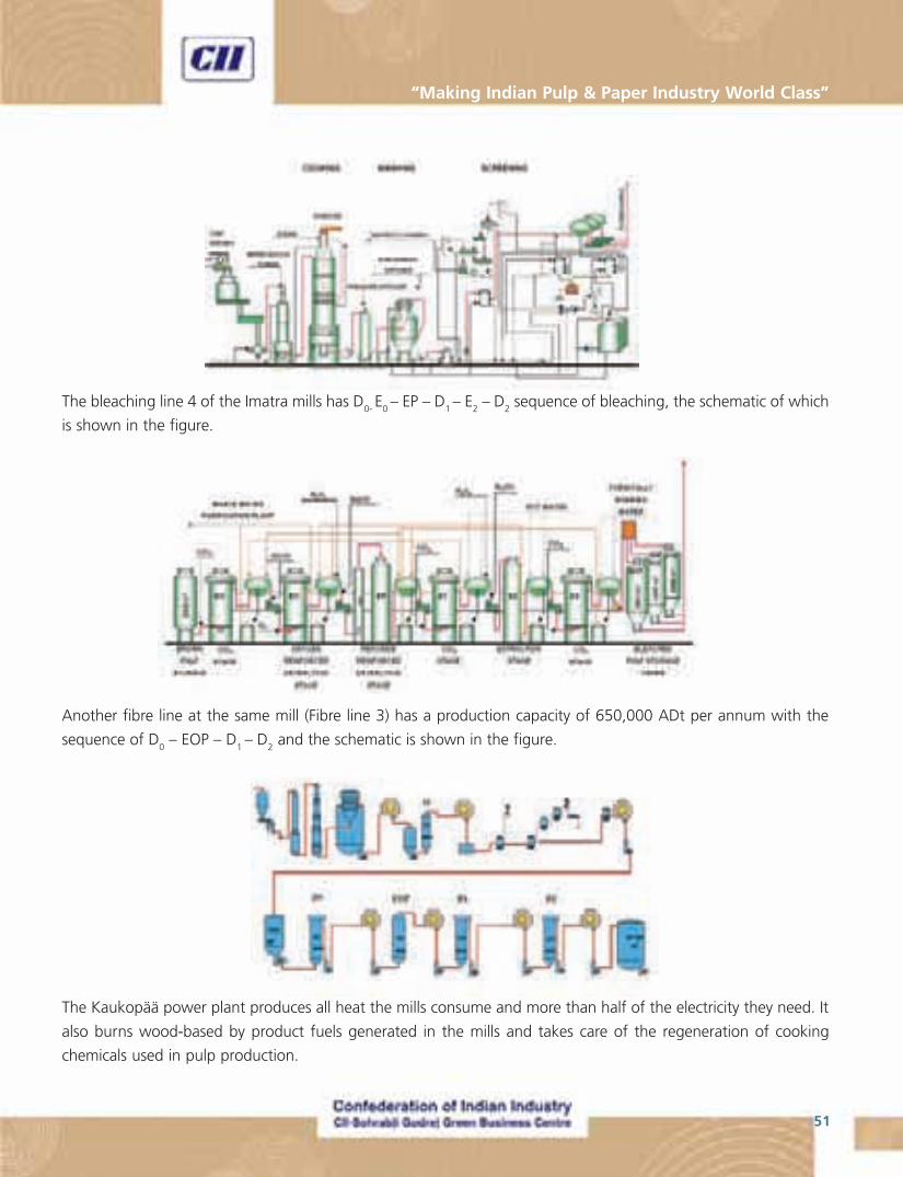
51
“Making Indian Pulp & Paper Industry World Class”
The bleaching line 4 of the Imatra mills has D0- E0 – EP – D1 – E2 – D2 sequence of bleaching, the schematic of which
is shown in the figure.
Another fibre line at the same mill (Fibre line 3) has a production capacity of 650,000 ADt per annum with the
sequence of D0 – EOP – D
1 – D
2 and the schematic is shown in the figure.
The Kaukopää power plant produces all heat the mills consume and more than half of the electricity they need. It
also burns wood-based by product fuels generated in the mills and takes care of the regeneration of cooking
chemicals used in pulp production.
National & International Best Practices - Pulp & Paper Industry
52
Thermal Efficiency Enhancement
Energy supplied to the plant of individual fuel contribution is given below.
FUEL GWh FUEL GWh
Black Liquor 4821 NG 564
Bark 1328 OIL 6
NG 469
Sub-Total 6149 1039
% [86%] [14%]
Total 7188
The thermal efficiency is enhanced by using secondary condensate heat in preheating boiler makeup water.
Substitution of imported fossil fuel (Natural gas) with Bio-fuels (wood) up to 90% and fuel drying has reduced fuel
consumption to 75 GWh/yr.
Power boiler
Back pressure turbine
The breakup of power consumption inside the plant for the year 2007 is given below
� Self generation : 825 GWhr/yr (60%)
� Purchased power : 542 GWhr/yr (40%)
� Total power consumption : 1367 GWhr/yr (100%)
53
“Making Indian Pulp & Paper Industry World Class”
Electric power enhancement
Power to heat ratio is enhanced by raising steam pressure and temperature from 70 to 84 bar and 500 to 530°C.
Optimising turbine to process steam and energy efficient rotating machines with VFD’s has increased on-site power
generation to 615 GWh/yr.
Water conservation schemes
Maximising condensate return and closed cycle cooling, reuse and recycle are the water conservation schemes
being carried out in the mill.
Waste management
The waste management measures that are being taken are
� Hot effluent cooled through cooling tower
� Effluent cooled to 35°C and then discharged
� Primary sludge fired in Boiler
Findings
The most significant saving potential relates to more efficient use of secondary heat, increasing of the power to
heat ratio by means of improved steam control system concept and reduction of natural gas firing. For example,
the improved steam control concept suggested would increase the on-site power generation by approximately 14
Gwh per annum. Improved pre heating of makeup water by means of hot condensates would lead to a total
reduction of approximately 74 GWh fuel per annum in fuel consumption.
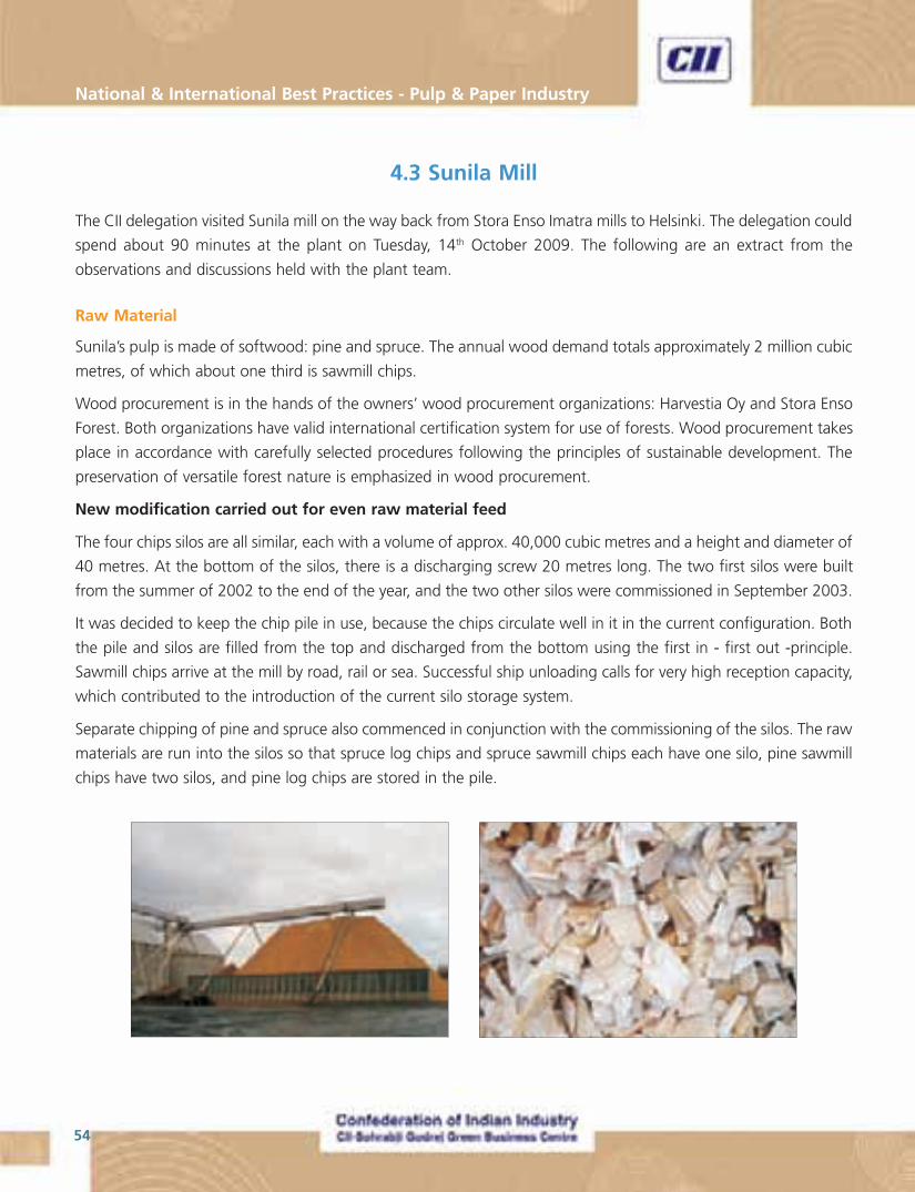
National & International Best Practices - Pulp & Paper Industry
54
4.3 Sunila Mill
The CII delegation visited Sunila mill on the way back from Stora Enso Imatra mills to Helsinki. The delegation could
spend about 90 minutes at the plant on Tuesday, 14th October 2009. The following are an extract from the
observations and discussions held with the plant team.
Raw Material
Sunila’s pulp is made of softwood: pine and spruce. The annual wood demand totals approximately 2 million cubic
metres, of which about one third is sawmill chips.
Wood procurement is in the hands of the owners’ wood procurement organizations: Harvestia Oy and Stora Enso
Forest. Both organizations have valid international certification system for use of forests. Wood procurement takes
place in accordance with carefully selected procedures following the principles of sustainable development. The
preservation of versatile forest nature is emphasized in wood procurement.
New modification carried out for even raw material feed
The four chips silos are all similar, each with a volume of approx. 40,000 cubic metres and a height and diameter of
40 metres. At the bottom of the silos, there is a discharging screw 20 metres long. The two first silos were built
from the summer of 2002 to the end of the year, and the two other silos were commissioned in September 2003.
It was decided to keep the chip pile in use, because the chips circulate well in it in the current configuration. Both
the pile and silos are filled from the top and discharged from the bottom using the first in - first out -principle.
Sawmill chips arrive at the mill by road, rail or sea. Successful ship unloading calls for very high reception capacity,
which contributed to the introduction of the current silo storage system.
Separate chipping of pine and spruce also commenced in conjunction with the commissioning of the silos. The raw
materials are run into the silos so that spruce log chips and spruce sawmill chips each have one silo, pine sawmill
chips have two silos, and pine log chips are stored in the pile.
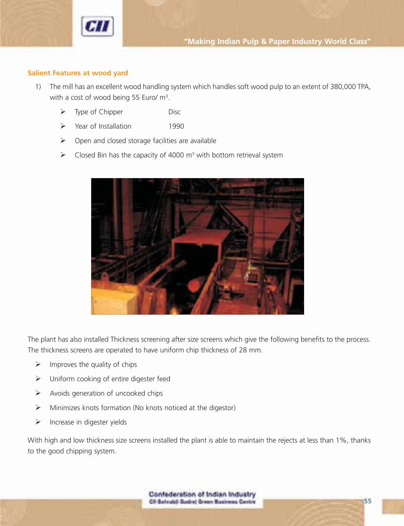
55
“Making Indian Pulp & Paper Industry World Class”
Salient Features at wood yard
1) The mill has an excellent wood handling system which handles soft wood pulp to an extent of 380,000 TPA,
with a cost of wood being 55 Euro/ m3.
� Type of Chipper Disc
� Year of Installation 1990
� Open and closed storage facilities are available
� Closed Bin has the capacity of 4000 m3 with bottom retrieval system
The plant has also installed Thickness screening after size screens which give the following benefits to the process.
The thickness screens are operated to have uniform chip thickness of 28 mm.
� Improves the quality of chips
� Uniform cooking of entire digester feed
� Avoids generation of uncooked chips
� Minimizes knots formation (No knots noticed at the digestor)
� Increase in digester yields
With high and low thickness size screens installed the plant is able to maintain the rejects at less than 1%, thanks
to the good chipping system.

National & International Best Practices - Pulp & Paper Industry
56
Other useful information
� Bark from the wood is burnt in boiler – after pressing to more than 40% dryness
� Upto 45 – 50 % dryness achieved
� Uses perforated drum type press
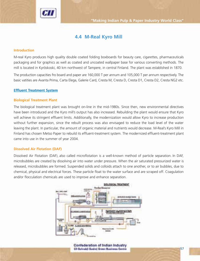
57
“Making Indian Pulp & Paper Industry World Class”
4.4 M-Real Kyro Mill
Introduction
M-real Kyro produces high quality double coated folding boxboards for beauty care, cigarettes, pharmaceuticals
packaging and for graphics as well as coated and uncoated wallpaper base for various converting methods. The
mill is located in Kyröskoski, 40 km northwest of Tampere, in central Finland. The plant was established in 1870.
The production capacities fro board and paper are 160,000 T per annum and 105,000 T per annum respectively. The
basic vatities are Avanta Prima, Carta Elega, Galerie Card, Cresta M, Cresta D, Cresta D1, Cresta D2, Cresta NG2 etc.
Effluent Treatment System
Biological Treatment Plant
The biological treatment plant was brought on-line in the mid-1980s. Since then, new environmental directives
have been introduced and the Kyro mill’s output has also increased. Rebuilding the plant would ensure that Kyro
will achieve its stringent effluent limits. Additionally, the modernization would allow Kyro to increase production
without further expansion, since the rebuilt process was also envisaged to reduce the load level of the water
leaving the plant. In particular, the amount of organic material and nutrients would decrease. M-Real’s Kyro Mill in
Finland has chosen Metso Paper to rebuild its effluent-treatment system. The modernized effluent-treatment plant
came into use in the summer of year 2004.
Dissolved Air Flotation (DAF)
Dissolved Air Flotation (DAF), also called microflotation is a well-known method of particle separation. In DAF,
microbubbles are created by dissolving air into water under pressure. When the air saturated pressurized water is
released, microbubbles are formed. Suspended solids and colloids attach to one another, or to air bubbles, due to
chemical, physical and electrical forces. These particle float to the water surface and are scraped off. Coagulation
and/or flocculation chemicals are used to improve and enhance separation.
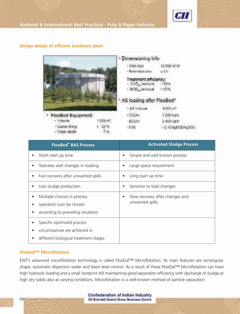
National & International Best Practices - Pulp & Paper Industry
58
Design details of effluent treatment plant
FlooDaf™ Microflotation
EWT’s advanced microflotation technology is called FlooDaf™ Microflotation. Its main features are rectangular
shape, automatic dispersion water and basin level control. As a result of these FlooDaf™ Microflotation can have
high hydraulic loading and a small footprint still maintaining good separation efficiency with discharge of sludge at
high dry solids also at varying conditions. Microflotation is a well-known method of particle separation.
59
“Making Indian Pulp & Paper Industry World Class”
General Features of the FlooDaf™ Microflotation
� One floor structure, only 0.9 m water depth
� Low space requirement
� Good separation efficiency over large particle area
� Good tolerance for hydraulic and solid variations
� High solid concentration in the sludge
� Flexibility in changing the operational situations
Advantages of the FlooDaf ™ Microflotation
� Reliable and recognized systems - over 200 references worldwide
� Economic construction
� Low maintenance costs
� Competitive operating costs
� After-sales support
FlooDaf is claimed to take care of the following aspects
� Efficient mixing of incoming water, air and polymer
� Good flock formation
� Low shear forces
� Eliminate turbulences
� Equal water distribution to whole gross section
� Utilization of total flotation surface efficiently
Design and operating values before and after modification
Design values for the effluent treatment system installed at M-Real Kyro mill are as follows. (Values are for the
effluent after primary clarifier)
� Quantity of effluent : 12000 m3/day
� SSin : < 350 mg/l
� SCODCr : < 1200 mg/l
� SSout
: < 30 mg/l
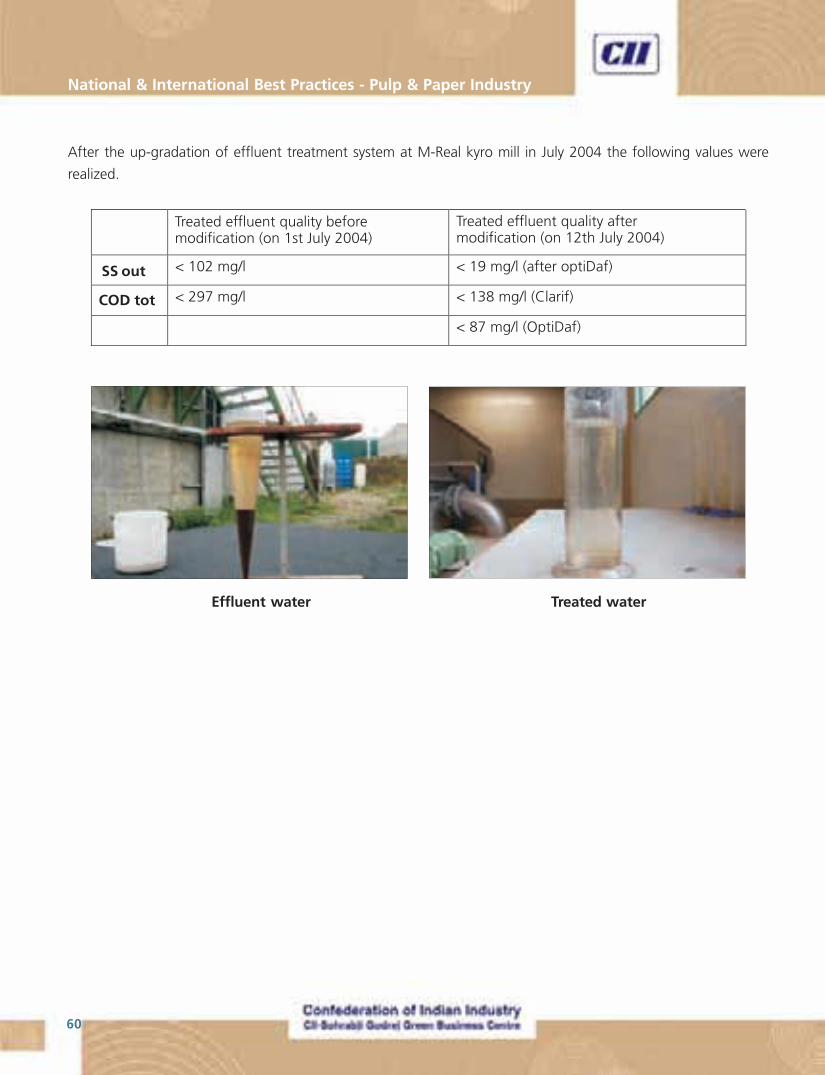
National & International Best Practices - Pulp & Paper Industry
60
After the up-gradation of effluent treatment system at M-Real kyro mill in July 2004 the following values were
realized.
Effluent water Treated water

61
“Making Indian Pulp & Paper Industry World Class”
4.5 Stora Enso, Stracel Mill
Introduction
The Stracel Company is part of the UPM Group. Situated in Strasbourg, France, the company enjoys an ideal
geographical location in the heart of European economic activity, but close to abundant forests and wood supplies.
The Stracel mill produces high quality magazine paper – UPM Satin and UPM Matt – obtained from sawmill chips
and round wood from the first thinning. The mill’s PM 1 runs at a speed of 1,500 m/min and produces an 8.48 m
wide sheet. The annual production capacity is 270,000 tonnes.
The Stracel mill operations date back to 1937, when Cellulose de Strasbourg built a sulfite pulp mill along the
Rhine River. Stracel’s newsprint mill and 850 metric tons/day thermo-mechanical pulp (TMP) plant were built on a
green-field site after Finland’s UPM-Kymmene acquired the operations in 1988. The new complex, built by the
same project team that had worked on Jämsänkoski’s PM 5 and other Finnish paper mills began operations on Oct.
25, 1990. The company continues to operate a nonintegrated 140,000 tons/year bisulphite pulp mill nearby. It’s
also fitting that a newsprint mill is located in the city where Johannes Gutenberg developed his printing process.
The pulp mill uses as much as 80% purchased sawmill chips—primarily spruce—for its TMP process. The rest is
roundwood. About half the chips come from German sawmills in the Black Forest, half from French sawmills in the
Vosges. Capacity is 850 metric tons/day.
Stracel claims a 95–96% yield from its TMP process. For brightening, the mill uses dithionite (sodium hydrosulfite:
Na2S2O4). Both elemental chlorine-free and totally chlorine-free, chemical market pulps are produced at the
bisulphite pulp mill, using oxygen, hydrogen peroxide, and chlorine dioxide for bleaching.
A view of the (thermo-mechanical) sunds refiners installed at the mill.
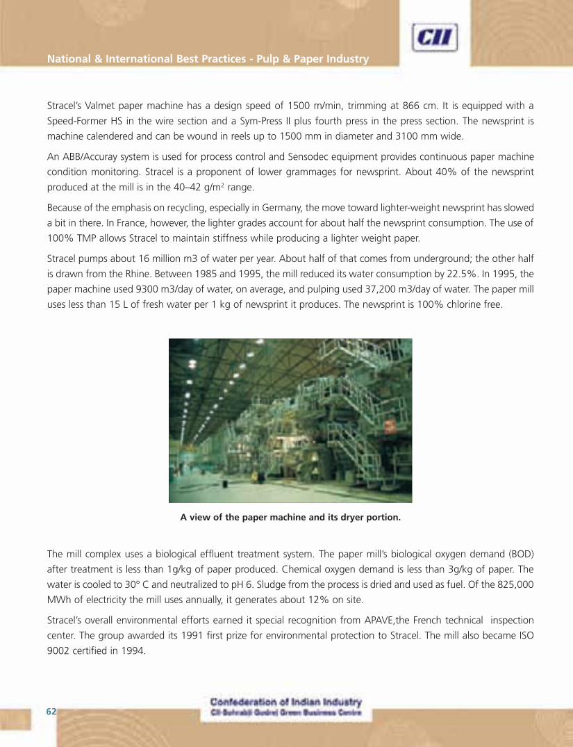
National & International Best Practices - Pulp & Paper Industry
62
Stracel’s Valmet paper machine has a design speed of 1500 m/min, trimming at 866 cm. It is equipped with a
Speed-Former HS in the wire section and a Sym-Press II plus fourth press in the press section. The newsprint is
machine calendered and can be wound in reels up to 1500 mm in diameter and 3100 mm wide.
An ABB/Accuray system is used for process control and Sensodec equipment provides continuous paper machine
condition monitoring. Stracel is a proponent of lower grammages for newsprint. About 40% of the newsprint
produced at the mill is in the 40–42 g/m2 range.
Because of the emphasis on recycling, especially in Germany, the move toward lighter-weight newsprint has slowed
a bit in there. In France, however, the lighter grades account for about half the newsprint consumption. The use of
100% TMP allows Stracel to maintain stiffness while producing a lighter weight paper.
Stracel pumps about 16 million m3 of water per year. About half of that comes from underground; the other half
is drawn from the Rhine. Between 1985 and 1995, the mill reduced its water consumption by 22.5%. In 1995, the
paper machine used 9300 m3/day of water, on average, and pulping used 37,200 m3/day of water. The paper mill
uses less than 15 L of fresh water per 1 kg of newsprint it produces. The newsprint is 100% chlorine free.
A view of the paper machine and its dryer portion.
The mill complex uses a biological effluent treatment system. The paper mill’s biological oxygen demand (BOD)
after treatment is less than 1g/kg of paper produced. Chemical oxygen demand is less than 3g/kg of paper. The
water is cooled to 30° C and neutralized to pH 6. Sludge from the process is dried and used as fuel. Of the 825,000
MWh of electricity the mill uses annually, it generates about 12% on site.
Stracel’s overall environmental efforts earned it special recognition from APAVE,the French technical inspection
center. The group awarded its 1991 first prize for environmental protection to Stracel. The mill also became ISO
9002 certified in 1994.
63
“Making Indian Pulp & Paper Industry World Class”
During the visit to Stracel Mill, the following points were observed and some of these are coveredbelow, in detail.
1. Equipped with Shoe press with the result dryness entering the drying section as 49%
2. Equipped with on-line film coater for LWC, manufacturing 48-70 gsm paper. At the time of visit the machine
was running at coat weight of 15 gsm on 48 gsm paper(Means base weight paper gsm 33 only)
3. Equipped with Opti load calendar performing the job of off-machine super calendaring with the result
saving in space, operational cost, losses and capital investment also
4. Manufacturing LWC of gloss ranging from 15 to 55 gloss units, machine speed is 1550 MPM , Deckle 8.48
M and water consumption is 12 M3/T of paper, machine production is around 2,80,000 MT/annum
A complete write up on Opti calendar and press part configuration is enclosed as presented by M/s Metso during
the discussions.
Case Study No. 1
Installation of Shoe press before dryer part of the paper machine.
Shoe presses can be used on pulp, paper and board machines. The structure of the Shoe press comprises of an
enclosed, hydrodynamic lubricated press shoe with a fixed or variable crown roll as a counter roll. The counter roll
type depends on the ratio between machine width and desired line pressure.
Shoe presses generally comprise a press shoe and a counter roll which form an extended nip therebetween through
which a running fibrous web is carried for treating the web, such as for dewatering the web in the press section of
a paper machine. Shoe presses generally also comprise pressure-actuatable piston-and-cylinder units, also referred
to as loading cylinders, which are distributed along the press shoe in one or more rows in the longitudinal direction
of the press shoe and adapted to press the press shoe against the counter roll.
Shoe presses can be set in either on top or bottom position. The pressure profile can be altered, enabling an
extremely even pressure to be applied to bulk sensitive qualities along the whole length of the nip. For qualities
capable of withstanding higher pressures, the pressure profile can be set far higher, maximising the dryness
percentage. This construction ensures long life for the belt, short belt replacement time, and low maintenance
needs. Some modern small and medium shoe presses are specially designed for a considerable increase of dryness
with reasonable investment costs, making this shoe press a realistic alternative for smaller machines as well. Its
compact construction makes it possible to be located into very limited spaces. The hydraulic space demand has
been optimized by incorporating separate lubricating and hydraulic equipment.
Due to the shoe press installed at the Stracel mill newsprint paper machine, the dryness of sheet entering the dryer
part is 49%. This reduces the steam consumption substantially and, in most cases, this energy saving will also pay
back the investment cost within three years.
National & International Best Practices - Pulp & Paper Industry
64
Advantages of installing shoe press are as follows.
1. Increases the dryness of paper entering the press part. This reduces the drying load requirement and there
by reduces the steam consumed in the dryer section. Some studies indicated an increase in dryness by 2.4
to 3% which results in steam consumption reduction of upto 8% in the dryer part
2. In cases where the dryer part is the bottleneck for increasing production, a shoe press can help in increasing
production rate substantially and there by reduce Specific energy consumption. A retrofit is expected to
show a 15% increase in production, in-line with that reported by some mills
3. It is also believed that a shoe press will make will make production of new quality papers and boards with
improved properties possible
Case Study No. 2
Installation of optiload calendar to perform online Super-Calendaring.
Calenders have come a long way since the days when steel-rolled machine calender tacks were mainly used to
remove lumps and even up the caliper profile. Soft calendering, which developed rapidly in the late 1980s and early
1990s, is now a standard technology for many paper and board grades. Lightweight coated and soft-nip uncoated
mechanical papers that used to require supercalendering are now produced in mills pushing the limits of soft
calenders. However, the newest multi-roll calenders are even more innovative, and provide capabilities to papermakers
previously limited to slow, high maintenance off-machine supercalenders.
There are two commercial multi-roll calenders available: Valmet’ OptiLoad and Voith Sulzer Paper Technology’
Janus calender. Both units are targeted at new installations on- and off-machine, as well as for rebuilds of existing
supercalenders.
In off-machine applications, cost savings compared to supercalendering is a key selling point. For example, in new
or rebuild situations, two supercalenders could be replaced by one multi-roll unit. It would require less staffing and
the new cover materials provide longer life and, thus, less downtime.
An advantage when located on-machine is that no additional staff is required vs the staff needed to run a
supercalender, and they can often be installed in existing space on-machine. This avoids the cost of moving reels,
winders, etc. associated with installing two or more soft-calenders. For example, energy use (for equal sheet
finishing) on the Janus is stated to be much less than soft calendering and modestly less than supercalendering.
The main advantage vs soft calendering is much lower heating energy requirements.
Is online Operation the Future? The inclusion of a multi-roll calender on-machine, while seeming to be the way
of the future for many commodity grades such as uncoated mechanical, raises the question that is probably of
most concern to papermakers: How will the uses of this equipment on-machine impact operating efficiency?
Specific issues of concern include cover life, threading at PM speed, motor maintenance issues (since the rolls are
driven), and, of course, paper quality.
65
“Making Indian Pulp & Paper Industry World Class”
One of the major challenges of online operation had been was to operate these units at the design speed of new
machines. But recent advancements have removed these from the list of concerns for a papermaker.
Valmet’ design, now taken over by Metso, differs from Voith’ in the way the rolls are loaded. In the OptiLoad, the
same nip load can be used in all nips from the top to the bottom of the stack. In conventional multi-nip stacks (i.e.,
supercalenders) most of the work is done in the bottom nips, because the weight of the rolls themselves means
most of the nip force is on the bottom, with only light loading on the top. In the OptiLoad, however, the dead load
impact of the stack is relieved by hydraulically compensating for the weight of the intermediate rolls. Additional
loading can then be applied by hydraulically loading the cylinders. As a result, each nip can do the same amount of
work, or can be loaded the same. In the Janus calender, there is an increase in loading from top to bottom, which
Voith believes is the preferred method. The Janus can also provide a hot variable crown roll which allows caliper
profiling. Observers appear mixed on whether either design has an advantage.
In soft calenders used to produce high-quality grades, the range of temperature required has led to the use of oil
as the heating medium in the steel roll. The oil is heated, often by use of natural gas, and then is pumped through
the hot roll, which contacts the covered roll (which has crown control capabilities). In contrast, the use of a multi-
roll approach means that lower temperatures can be used. Therefore, mill process steam, rather than the more
complex and expensive oil heating system, can supply heat. Also, energy savings can be considerable. In a multi-roll
calender, the use of smaller diameter rolls with less surface area for heat loss, in conjunction with the fact that the
heated rolls work against two opposing rolls vs one in a conventional singe nip calender, saves energy.
Details on the covers used, whether it is grind cycle or resistance to marking, is probably the key technical question
asked by operating personnel. The advent of new synthetic or polymer roll covers has been one of the major
developments making these new systems possible. Each manufacturer provides their own soft roll covers, but
details are considered confidential.
What is a multi-roll calender?
Traditionally, the grade a mill wanted to make determined one of two options in terms of finishing the sheet.
For low- to moderate smoothness grades, soft calendering could achieve a gloss range of about 70 and a
smoothness of around 1.5 PPS S10. For grades with properties above this, such as rotogravure lightweight
coated, SCA, and coated free-sheet, supercalendering was required. However, the new calenders provide the
capability to attain higher smoothness than machine calenders, and higher speeds considerably above the
1,475 to 2,950 ft/min (450 to 900 m/min) range of a supercalender. The key has been development of covers
that can withstand both higher temperatures than a supercalender and higher impact than a soft calender
(both frequency and line load).
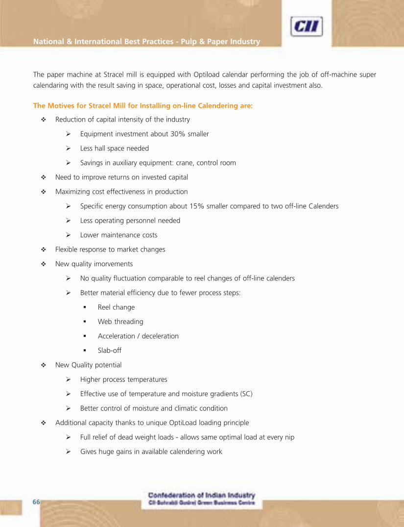
National & International Best Practices - Pulp & Paper Industry
66
The paper machine at Stracel mill is equipped with Optiload calendar performing the job of off-machine super
calendaring with the result saving in space, operational cost, losses and capital investment also.
The Motives for Stracel Mill for Installing on-line Calendering are:
� Reduction of capital intensity of the industry
� Equipment investment about 30% smaller
� Less hall space needed
� Savings in auxiliary equipment: crane, control room
� Need to improve returns on invested capital
� Maximizing cost effectiveness in production
� Specific energy consumption about 15% smaller compared to two off-line Calenders
� Less operating personnel needed
� Lower maintenance costs
� Flexible response to market changes
� New quality imorvements
� No quality fluctuation comparable to reel changes of off-line calenders
� Better material efficiency due to fewer process steps:
� Reel change
� Web threading
� Acceleration / deceleration
� Slab-off
� New Quality potential
� Higher process temperatures
� Effective use of temperature and moisture gradients (SC)
� Better control of moisture and climatic condition
� Additional capacity thanks to unique OptiLoad loading principle
� Full relief of dead weight loads - allows same optimal load at every nip
� Gives huge gains in available calendering work
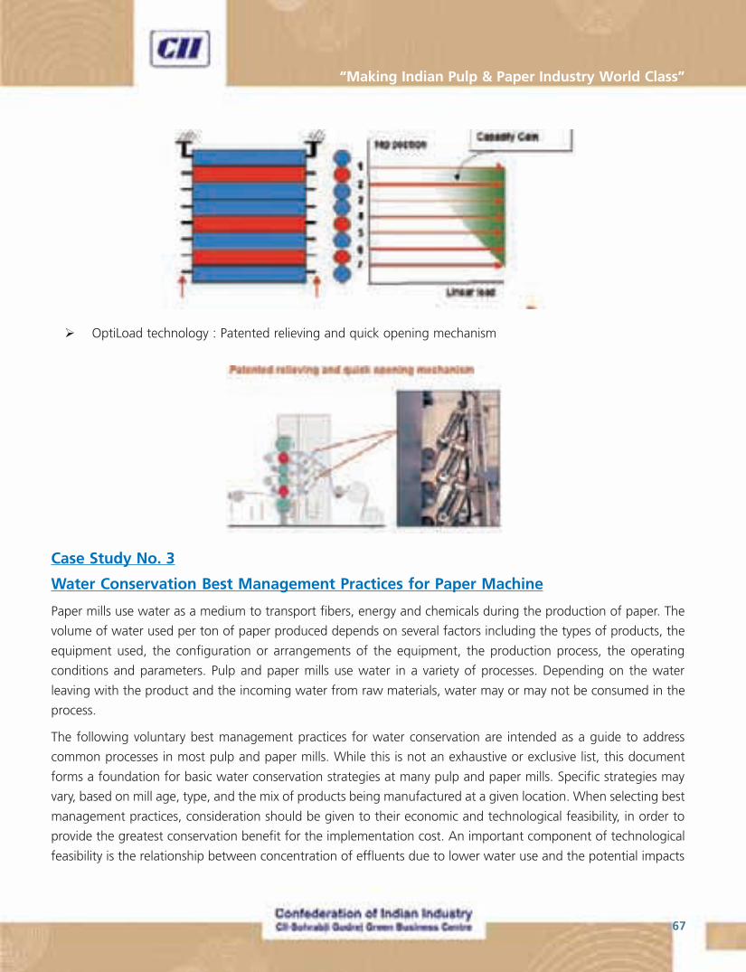
67
“Making Indian Pulp & Paper Industry World Class”
� OptiLoad technology : Patented relieving and quick opening mechanism
Case Study No. 3
Water Conservation Best Management Practices for Paper Machine
Paper mills use water as a medium to transport fibers, energy and chemicals during the production of paper. The
volume of water used per ton of paper produced depends on several factors including the types of products, the
equipment used, the configuration or arrangements of the equipment, the production process, the operating
conditions and parameters. Pulp and paper mills use water in a variety of processes. Depending on the water
leaving with the product and the incoming water from raw materials, water may or may not be consumed in the
process.
The following voluntary best management practices for water conservation are intended as a guide to address
common processes in most pulp and paper mills. While this is not an exhaustive or exclusive list, this document
forms a foundation for basic water conservation strategies at many pulp and paper mills. Specific strategies may
vary, based on mill age, type, and the mix of products being manufactured at a given location. When selecting best
management practices, consideration should be given to their economic and technological feasibility, in order to
provide the greatest conservation benefit for the implementation cost. An important component of technological
feasibility is the relationship between concentration of effluents due to lower water use and the potential impacts
National & International Best Practices - Pulp & Paper Industry
68
that may have on receiving waters, process equipment due to increased corrosivity, and the finished product.
Generic Recommendations
A significant reduction in fresh water usage can be realized by optimizing the design and operation of the whitewater
system in the mill. Whitewater should be the primary source of water for pulping especially when its color is
compatible with the color of the paper being produced. The use of fresh water for Headbox, Breast, Knockoff,
Forming Fabric, and Wire Return Roll Showers for most paper machines can be substituted with screened and
clarified whitewater. Process piping should be inspected for leaks and repaired as soon as possible upon detection.
All plant personnel should be educated about these water conservation strategies through a facility-wide program
in order to facilitate achieving the water conservation goals specified below.
Pulper
Whitewater should be used for making stock. Whitewater from the machine room or the whitewater chest should
be the first source of water for stock preparation, if the color is acceptable for the grade of paper to be produced.
Vacuum Seal Water
The temperature of effluent seal water is higher than that of the feed water. Besides the increase in temperature, the
main contaminants in seal water are fiber and felt hair. There could also be some solids pick up from the felt. A cooling
tower can be installed to reduce the temperature and screens and filters can be used to remove the other contaminants.
However, this system cannot be run as a closed loop due to conductivity build. The high conductivity can greatly decrease
the life of the pumps due to attacks on metallurgy. It must be continuously purged. Another option is to route the seal
water to a whitewater chest or back to the bleach plant for stock dilution. The cleaned water can then be reused. It is also
possible to cascade the cooler seal water effluent from the high vacuum pumps (couch, flat boxes) to the low vacuum
pumps (press, felt conditioning, etc.). The hot water now generated can be stored and used for stock preparation.
Non-Contact Cooling Water
Non-contact cooling water should be collected and stored in the hot water storage tank. Water from this tank can
be used for stock preparation in the pulper, preparation of additives, colors and finishing materials. The viability of
doing this depends on the heat balance in the mill’s water system.
Felt Cleaning Water
Fresh water is often utilized for felt cleaning on paper machines and presses and discarded to the sewer thereafter.
The used water would typically contain felt (hair) and low concentrations of fiber, color and stock additives. It is
possible to separate the felt/hair component and reuse the water upstream in stock preparation.
Showers
Check to see if high-pressure, low-volume showers instead of low-pressure, high-volume showers can be used for
every application. Clarified white water can be used for guide edge knock-off showers, guide showers and breast
69
“Making Indian Pulp & Paper Industry World Class”
Part 2
Best Practices Implemented in
Indian Pulp & Paper Mills

National & International Best Practices - Pulp & Paper Industry
70
71
“Making Indian Pulp & Paper Industry World Class”
List of Best Practices Implemented in
Indian Pulp & Paper Mills
1. Installation of Down Flow Lo Solids Cooking System - APPM’s Experience (APPM)
2. ECF Alkaline Extraction Filtrate Recycling (TNPL)
3. Features of the latest Paper Machine installed at EMAMI Paper Mills, Balasore (EMAMI)
4. Steam optimisation in soot blowing of new High Pressure Chemical Recovery Boiler (SPB)
5. Using DIP sludge as a fuel substitute for Power Boiler (EMAMI)
6. Chloride removal from Recovery cycle – a low cost option (TNPL)
7. Impact of medium consistency ECF sequence on Water Consumption and Pollution Load (TNPL)
8. Activated sludge process with MBBR technology (ITC – PSPD, Bhadrachalam)
9. Water Conservation activities at J K Paper Mills, Rayagada (JKPM)
10. Advanced Process Controllers installed in areas other than Pulp Mill (ITC – PSPD, Bhadrachalam)

National & International Best Practices - Pulp & Paper Industry
72

73
“Making Indian Pulp & Paper Industry World Class”
Best Practices No. 1
Installation of Down Flow Lo Solids Cooking System
Unit : The Andhra Pradesh Paper Mills Ltd., Rajahmundry (APPM)
Introduction
APPM installed Down flow Lo solids continuous cooking system suppled by M/s Andritz OY, Finland in the year
2006 and since then the plant was in operation. The plant operation is easy and the performance is quite satisfactory.
It is totally automated plant. All plant operations are carried out through DCS from central control room.
The advantages of Down flow Lo-solids continuous cooking system are:
1. High yield
2. Uniform quality of pulp
3. Good pulp strength
4. Easy operation
5. Less steam consumption
6. Less power consumption
7. No LVHC gases generation
Description of cooking system
The cooking system mainly consists of Turbo feed system and Down flow Lo-solids cooking system.Turbo feed System
Turbo Feed Digester Feed System
National & International Best Practices - Pulp & Paper Industry
74
One of the main equipment in the feed system is diamond back chip bin, which ensures an even distribution to
make sure all chips subjected to effective air removal and prevents channeling of the chip flow. Steam generated in
the reboiler is used for pre-steaming the chips. Pre steamed chips are metered through metering screws and fed to
the digester with the help of chip pumps. The Liquor Surge Tank stabilizes and helps control the liquor level in the
Chip Tube via an equalization line.
Down Flow lo Solids Cooking
The objective of Lo-Solids cooking is to minimize the concentration of dissolved organics throughout the bulk
phase of delignification while maintaining an “even” alkali profile, minimum cooking temperatures, and minimum
concentrations of dissolved lignin with pulp at the end of the cook.
To achieve this objective, multiple extractions, split white liquor additions and split filtrate additions adopted.
Chips are pumped to the top of digester by turbo feed pumps. Top separator, on the top of the digester, distributes
the chips to impregnation zone of the digester and return liquor flows back to chip tube through feed circulation
cooler. MP steam is added at the top of digester to maintain top temperature of digester, approximately 1450C.
The chips are impregnated in impregnation zone with liquor. After impregnation zone, the chips enter the upper
cooking circulation zone. The impregnation liquor is extracted from the uppermost set of extraction screens and
directed through steam economizer, where make-up black liquor and white liquor are pre-heated before being fed
to cooking circulation. The extracted liquor after economizer is fed to re-boiler where heat transfer is taken place
between liquor and hot water. Hot water flashes and LP steam is generated. This LP steam is utilized for steaming
the chips in diamond back chip bin.

75
“Making Indian Pulp & Paper Industry World Class”
After impregnation, the chips are in contact with hot up-flowing liquor from the cooking circulation (second set of
digester screens). This liquor heats the chips to the required cooking temperature of 150°C. Cooking circulation
liquor is composed of hot white liquor, brown stock filtrate, wash extraction and cooking circulation extract. By
adding these liquors to cooking circulation, the alkali and dissolved solids concentrations are kept uniform through
out cooking, which gives a better pulp quality compared to addition of chemicals at a single point. A portion of this
liquor then flows upward to the upper extraction screens and the remaining liquor flows downward to the co-
current cooking zone.
After co-current cooking zone, the rest of the liquor is extracted from the digester at the wash extraction screens.
Washing in the digester is accomplished by passing wash liquor in the counter-current direction through the pulp
in the digester bottom wash zone.
Cold blow filtrate passes upwards in the pulp column and is continuously extracted through the wash extraction
screens. The wash extract is extracted from the digester through one row of screen plates on the digester wall with
two headers.
Pulp is blown continuously to blow tank by outlet device.
There is no LVHC generation in Lo-solids continuous cooking system.
Performance of continuous system
Down flow Lo solids cooking system has been in operation for last two and half years.
Our observations on the performance of cooking system are as follows:
1. The operation of the digester system is quite easy and operational flexibility is excellent
2. Uniform cooking. Kappa no is around 16
3. % AA on BD chips charged ,on average is 18-19
4. The quality of unbleached pulp improved when compared with pulp of conventional batch digester system.
Comparison of unbleached pulp strength properties are as follows:
5. Knots content are 0.5% which is less than conventional batch system
6. Specific power consumption is 40 kwh/T of U.B. plulp
Strength properties Conventional Lo solids cooking system
batch digester
Burst factor 36 48.9
Breaking length, Meters 6085 7930
Tear factor 57 70
Double folds 16 46
National & International Best Practices - Pulp & Paper Industry
76
Problems encountered in continuous system:
Although the system offers satisfactory performance, we have experienced few problems which are enumerated
below:
Tripping of chip pumps
The tripping of chip pumps are due to entry of foreign materials with chips. It was addressed with the help of
magnetic separator installed on feed conveyor to airlock screw feeder.
Wear & tear of chip pump internals due to erosion:
Initially we faced problem of wear and tear on the internals of Chip pump, control valves in liquor lines and some
parts of piping. After installing sand separating system in the return liquor line from the top of digester to chip
tube, there is no such problem.
Conclusion:
Down flow Lo solids cooking system is energy efficient and environmental friendly system. There is no odour gas
due to cold blow. The operation of the plant is easy and there is substantial improvement in strength properties of
the pulp.
7. Specific MP Steam consumption is 0.65T against specific steam consumption of conventional batch system
of 1.48T/T
8. Availability of digester for operations is 97%
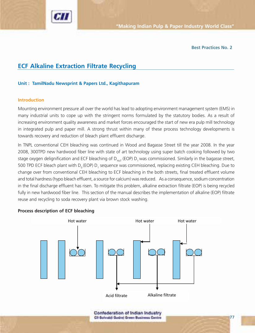
77
“Making Indian Pulp & Paper Industry World Class”
Best Practices No. 2
ECF Alkaline Extraction Filtrate Recycling
Unit : TamilNadu Newsprint & Papers Ltd., Kagithapuram
Introduction
Mounting environment pressure all over the world has lead to adopting environment management system (EMS) in
many industrial units to cope up with the stringent norms formulated by the statutory bodies. As a result of
increasing environment quality awareness and market forces encouraged the start of new era pulp mill technology
in integrated pulp and paper mill. A strong thrust within many of these process technology developments is
towards recovery and reduction of bleach plant effluent discharge.
In TNPL conventional CEH bleaching was continued in Wood and Bagasse Street till the year 2008. In the year
2008, 300TPD new hardwood fiber line with state of art technology using super batch cooking followed by two
stage oxygen delignification and ECF bleaching of DHoT (EOP) D1 was commissioned. Similarly in the bagasse street,
500 TPD ECF bleach plant with D0 (EOP) D
1 sequence was commissioned, replacing existing CEH bleaching. Due to
change over from conventional CEH bleaching to ECF bleaching in the both streets, final treated effluent volume
and total hardness (hypo bleach effluent, a source for calcium) was reduced. As a consequence, sodium concentration
in the final discharge effluent has risen. To mitigate this problem, alkaline extraction filtrate (EOP) is being recycled
fully in new hardwood fiber line. This section of the manual describes the implementation of alkaline (EOP) filtrate
reuse and recycling to soda recovery plant via brown stock washing.
Process description of ECF bleaching
National & International Best Practices - Pulp & Paper Industry
78
Pulp from Super batch digester is screened and washed in twin roll displacement press. Washed pulp is sent to
oxygen delignification (ODL) where it is further delignified in two step oxygen delignification stage. After ODL, pulp
is washed in a post oxygen displacement (PO) press prior to entering the bleaching.
Pulp from PO press is diluted and pumped to upward DHot tower through the pulp heater and chlorine dioxide mixer.
DHot
tower outlet pulp is diluted with D1 filtrate is pumped to dewatering press. The filtrate from D
Hot press is used as
dilution and the excess filtrate is pumped to liquor filter to recover the fiber before letting into effluent channel.
Pulp from DHot press is diluted and pumped to bottom of the EOP tower through oxygen mixer after the addition of
alkali and peroxide. Pulp from the top of the tower is diluted with hot water is pumped to dewatering press. The
filtrate from EOP press is used as dilution and the excess filtrate is drained into the effluent channel after recovering
the fiber.
Pulp from EOP press is diluted and pumped to up-flow D1 tower through chlorine dioxide mixer. Pulp from the top
of the tower is diluted with hot water and pumped to dewatering press. The filtrate from D1 press is used as dilution
and the excess filtrate is pumped to DHot stage for dilution. Pulp from the D1 press is diluted with paper machine
back water and pumped to storage tower. Dilution factor of 2-2.5 is maintained in all the stages.
Characteristics of Bleach Plant effluent
ECF bleach plant effluent consists of both acid and alkaline filtrates. In ECF bleaching it is desirable not to concentrate
inorganic substance along with organic substances. Alkaline waste water comprises a great deal of relatively high
molecular weight organic material and sodium, where as the acid waste water primarily consists of low molecular
weight organics and inorganic salts such as calcium, magnesium, chlorides and chlorate etc. If the acid and alkaline
filtrates are mixed, it becomes more difficult to separate different substances from the process flow in a subsequent
treatment which is detrimental in methods aiming at closing up the bleach plant. Foam generation may occur when
treating mixed waste water which can result in operating difficulties and increase in cost of defoamer (Erickson,
1995). Recycle directly into the weak black liquor to achieve an over all bleach plant reduction of 40% colour and
25% AOX, but with a 7% increase in chemical recovery evaporation load. Any recycling of alkaline filtrate into brown
stock fiber line must be done to a point were the weight percentage of dissolved solids equal or exceed those in the
alkaline concentration. Direct recycling of bleach plant alkaline filtrate for use as a wash water or dilution water on the
pulp system can be pushed back to the chemical recovery cycle. The concentrate may be added only as replacement
wash or dilution water for fresh water, it increases in chemical recovery evaporation load.
In effluents, COD and AOX compounds are not easily biodegradable in biological waste treatment systems. Therefore,
it is desirable to reduce the high molecular weight COD and AOX compounds in effluent by recovery and diversion
of the same to chemical recovery system without causing a significant impact of the evaporation load in chemical
recovery(Wearing, 1994). Alkaline filtrate contains much of the organic solids removed during bleaching as well as
most of the chromophoric bodies which are principally made of soluble organic compounds removed from the
pulp. Recycle or reuse of at least portion of EOP filtrate may reduce the level of organic solids and colour bodies
leaving the bleach plant.
79
“Making Indian Pulp & Paper Industry World Class”
Need for recycling of alkaline EOP filtrate
Soft water is being used in hardwood fiber line and bagasse street instead of process water due to extremely high
hardness in the mill water drawn from river Cauvery. EOP press roll perforation holes are getting plugged with
calcium scales due to high hardness of river water and also entry of non process elements mainly calcium from
wood chips, requiring frequent plant stoppages for cleaning the EOP press rolls leading to production loss. To
minimize this problem, process water is replaced with soft water. Sodium level in the process circuit and mill
effluent is increased significantly due to usage of soft water and also the back wash (having very high sodium as
well as inorganic TDS) in softener operation drained to effluent. To reduce the sodium concentration in the mill
effluent, possibility of reducing sodium discharge from the pulp mill effluent was studied in detail. The only option
is to recycle the alkaline filtrate to soda recovery plant through washing cycle.
Implementation of alkaline filtrate recycling
Alkaline filtrate from filter (recovery of suspended solids) going to the effluent drain is diverted to an intermediate
tank installed for recycling alkaline filtrate. Alkali filtrate from intermediate tank is pumped and used in post
oxygen press for washing in place of hot water. Dilution factor used in post oxygen press is 2 – 2.5. Thereby no
alkaline filtrate is going to effluent from hardwood ECF bleaching.
Additional benefits of alkaline filtrate recycling
In new hardwood fiber line, bleach plant alkaline effluent discharge was 1440 m3 per day. Hot water of equivalent
volume at 80°C used in post oxygen press washing was replaced with alkaline filtrate of 75 – 80°C. Alkali loss in PO
press was not affected by recycling of alkaline filtrate for dilution factor of 2.5. The same dilution factor was
maintained before recycling alkaline filtrate also. Hot water of 1440m3 per day at 80°C used in PO press becomes
excess due to alkaline extraction filtrate recycling. This quantity of hot water generation can’t be reduced in super
batch cooking as 175 – 200 m3 of fresh water per hr is required to reduce the temperature of hot black liquor
before supplying to soda recovery plant. About 60m3 per hr of excess hot water is pumped to chemical bagasse
ECF plant, thereby reducing 1440m3 of hot water and corresponding reduction in LP steam required for heating
fresh water. . Annual saving due to pumping of excess hot water from hardwood fiber line to Chemical bagasse
ECF plant is around Rupees 2 crores. Brightness of post oxygen press pulp and chlorine dioxide consumption
remains same before and after recycling of alkaline filtrate. Results are shown in Table-3.
National & International Best Practices - Pulp & Paper Industry
80
Incremental impact on recycling
If bleach plant filtrate is recycled in the pulp mill, the impact on chemical recovery system will be too high. Process
equipment such as black liquor evaporators are not constructed for recycling large quantity of waste water. In
addition, process equipment in the recovery system is very sensitive to chlorides and other inorganic substances
from the recovery of bleaching wash filtrates. Increased concentrations of inorganic cations and anions resulting
from bleach plant closure may cause negative impact, including formation of scale deposits and consumption of
bleach chemicals. Accumulation of chloride and potassium in recovery cycle adversely affects the operation of
boiler, which include plugging in super heater, corrosion of recovery boiler and increased steam demand.
The present process is preferably claimed in combination with a whole concept for closing up the bleach plant.
Hence, in case of ECF bleaching, such concept may include removal of chlorides and potassium by direct purging of
recovery boiler ESP ash or selective leaching of ESP ash and crystallization of sodium sulphate present in ESP ash.
The advantages of crystallization are a high recovery of sodium and sulphur with a high removal efficiency of
chlorides and potassium.
The kraft mills with high chlorides in their process cycle have difficulties in sustained operation, hence difficult for
complete bleach plant closure. Minimum purging is required until the non-process elements are no longer brought
into the mill
A key to successful recovery and recycle of bleach plant effluent is management of non process elements, controlled
purging are required for chlorides, potassium, phosphors, silica, aluminum, calcium, magnesium and Iron. Any mill
contemplating closure must be cautious about the negative impacts of buildup of non process elements and
design systems for controlling purges.
Purging of non-process elements in SRP cycle
In TNPL about 60-70 tons per day ESP ash is generated which contains 28% chlorides as NaCl and 6.8% as
potassium. 90% of chloride, 74% of potassium and 63% of sulphate are removed by running decanter of 30 tons
per day capacity installed for ESP ash handling system. Unrecovered sulphate in the filtrate is mixed with softner
effluent and further treated by adding burnt lime. Recovered sodium chloride is reused in softner plant. Calcium
sulphate and magnesium hydroxide salt precipitated from decanter filtrate is used for soil reclamation.
Summary
State of the art oxygen ECF bleaching of hardwood fiber line in TNPL is less sensitive to build of organics and metals
in highly closed water recycle circuits. ECF bleaching generates both acid and alkaline filtrates. As entire quantity of
alkaline filtrate (EOP
) generated is used in PO press, no alkaline filtrate is going to effluent from ECF bleaching of
hardwood fiber line. Alkali loss of PO press is not affected by recycling of alkaline filtrate. Brightness of PO press
pulp and chlorine dioxide consumption in bleaching remains same before and after recycling of alkaline filtrate.
Annual savings of energy due to pumping of excess hot water from hardwood ECF fiber line to chemical bagasse
ECF plant is around 2 crores. Due to recycling 1400-1500 kg of chloride per day is carried over to soda recovery
plant. Around 1.5 tons sodium per day going to effluent is recycled into the system.
81
“Making Indian Pulp & Paper Industry World Class”
New pulping and bleaching process facilitates partial closure of bleach plant effluent. Because of constant efforts
taken by TNPL towards implementation of eco-friendly practices, conservation techniques, latest technology in
pulping and bleaching, overall status of TNPL has come up, which has become competitive in present global
scenario.
Table - 3
Result of before and after alkaline filtrate recycling.

National & International Best Practices - Pulp & Paper Industry
82
Best Practices No. 3
Features of the latest Paper Machine installed at Emami Paper Mills
Unit : Emami Paper Mills (EMAMI), Balasore
Emami Paper Mills Ltd. has two paper mills Unit # 1 at Balasore and Unit # 2 at Kolkata. The Balasore mill was
expanded by installing a Newsprint Paper Machine (PM #3) production line, with all the auxiliaries and utilities.
Including this project the total installed capacity of EMAMI is 450 tpd (400 tpd in Balasore and 50 tpd in Kolkata).
The Paper Machine (PM 3)
Commissioned in 2008-09, this paper machine has state of the art features with most advanced online automation
provided by Honeywell, USA and ABB coupled with most advanced machinery from Beloit, USA; Kadant Inc, USA;
Voith, Germany.
Machine is designed to make the paper at a speed of 1200 meter per minute, and currently running at 1100 meter
per minute. It is the fastest machine in India running with 100% recycled pulp and making 45 gsm Newsprint.
Block diagram of the process is given below:
83
“Making Indian Pulp & Paper Industry World Class”
Paper Forming
The paper machine has most advanced forming Zone of BelBaie IV gap former from Beloit, USA. As on date, Emami
paper mills is the only mill in India that has BelBaie IV wire section.
Advantages
� Good Formation
� Good CD profile
� No two sidedness
Paper Pressing Zone
The paper machine has most advanced pressing zone equipped with Three Nip Press with Nippco Zone Control
Rolls and Ceramic Central Roll from Voith – Sulzer, Germany
Advantages
Best Control on Cross Moisture Profile of the Paper means best possible dimensional stability.
Paper Calendaring
The paper machine has best Calendaring system equipped with advanced Two Stack back to back Soft Nip Calendar
with Heated Thermo rolls and full Hydraulic control.
Advantages
� Two sidedness is significantly eliminated
� Superior Paper surface on both sides
� Uniform density of the Paper resulting in minimum hills and valleys and gives much better printability at par
with International Newsprint quality
Paper Machine Automation
The paper machine has latest Online Automation from Honeywell, USA for Cross Directional (CD) control of Basis
Weight, Caliper, and Moisture by Auto Slice, Devronizer and Calcoil HT.
Advantages
All the above basic requirements of Paper are uniformly maintained, which gives a constant quality printing throughout
with good Roll density.

National & International Best Practices - Pulp & Paper Industry
84
Major Highlights of PM 3 (Newsprint)
� Uniform basis weight and caliper
� Two sidedness is nearly eliminated
� Best possible smoothness on both sides
� Dirt and specs are negligible
� MD/CD ratio significantly improved
� Newsprint with best dimensional stability
� Uniform Reel Density
� Good runnability on printers as the paper is made on the machine at the Highest operating speed in India
� Automated reel wrapping with bar coding improves reel management
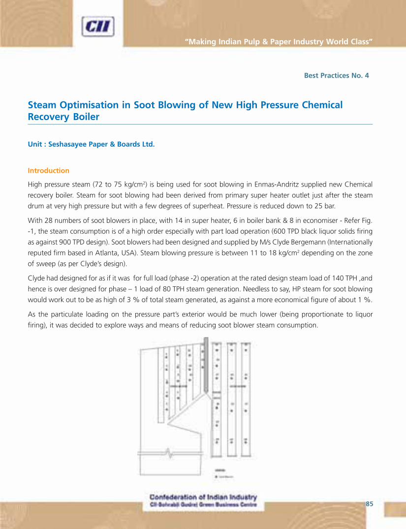
85
“Making Indian Pulp & Paper Industry World Class”
Best Practices No. 4
Steam Optimisation in Soot Blowing of New High Pressure ChemicalRecovery Boiler
Unit : Seshasayee Paper & Boards Ltd.
Introduction
High pressure steam (72 to 75 kg/cm2) is being used for soot blowing in Enmas-Andritz supplied new Chemical
recovery boiler. Steam for soot blowing had been derived from primary super heater outlet just after the steam
drum at very high pressure but with a few degrees of superheat. Pressure is reduced down to 25 bar.
With 28 numbers of soot blowers in place, with 14 in super heater, 6 in boiler bank & 8 in economiser - Refer Fig.
-1, the steam consumption is of a high order especially with part load operation (600 TPD black liquor solids firing
as against 900 TPD design). Soot blowers had been designed and supplied by M/s Clyde Bergemann (Internationally
reputed firm based in Atlanta, USA). Steam blowing pressure is between 11 to 18 kg/cm2 depending on the zone
of sweep (as per Clyde’s design).
Clyde had designed for as if it was for full load (phase -2) operation at the rated design steam load of 140 TPH ,and
hence is over designed for phase – 1 load of 80 TPH steam generation. Needless to say, HP steam for soot blowing
would work out to be as high of 3 % of total steam generated, as against a more economical figure of about 1 %.
As the particulate loading on the pressure part’s exterior would be much lower (being proportionate to liquor
firing), it was decided to explore ways and means of reducing soot blower steam consumption.
Fig 1 . Soot Blower Layout
National & International Best Practices - Pulp & Paper Industry
86
Design Specifications
Blow Time : 4 minutes
Section Soot Blower Steam Line Steam consumptionNo. Pressure kg/cm2 Tons/hr/blow
Super heater 1 to 14 15.3-17.3 7.3
Boiler Bank 15 to 20 14.3-15.3 6.6
Economiser 21 to 28 11.2-13.3 5.6
Details of the Identified Best Practice
Soot blowing scheme
Clyde-Bergemann [CB], Atlanta USA were awarded the contract of the entire Soot blowing system for the High
Pressure (65 kg/cm2) Chemical Recovery Boiler. Energy efficiency related features such as - patented CFE nozzle
design, multiple indexing & proprietary poppet valve - are unique with CB design. Brief of the above facets is
outlined in the following section.
Contoured Full Expansion [CFE] Nozzle
Higher Peak Impact Pressure [PIP] provided by CFE Nozzle ensures lower lance pressure (17 bar) as against a higher
lance pressure (25 bar) with conventional nozzles for achieving same PIP & cleaning efficacy. This would tantamount
to reduction in steam consumption by 20 to 30 %. This could be achieved because of total expansion of higher
pressure steam thereby eliminating loss of energy due to shock-waves.
Poppet Valve –Speciality
The poppet valve (of medium pressure) with pressure control orifice is provided so as to adjust the blowing pressure
independent of valve opening. ( Refer Fig.2 ). Pressure adjustment can be made external to pressure valve and
while soot blowing is in operation. Precise and quick adjustment with improved safety is specific features of the
item.
Soot blower pressure optimisation is easily achieved with the aid of poppet valve.
MULTIPLE INDEXING
Background:
In order to ensure total sweep of pressure part exterior off particulates, CB had developed the concept of multiple
indexing. See Fig. 3 showing the soot blowers in place.

87
“Making Indian Pulp & Paper Industry World Class”
Design concept:
� Offsets venturi to different angle through a linear movement at the end of each cycle, as can be seen from
Fig. 4.
� Accomplished by clutch in gearbox. Hence different helix followed for each cycle
� Infinite indexing capabilities.
� Offset time is 0.8 sec between Helix and Linear movement (resulting in phase shift )
Fig. 4
Mechanical features:
� Linear travel : ~11m
� Travelling speed : ~3m/min
� Helix : 125mm
Concept
Rotation of 0.8s out of phase with linear movement; setting in control panel.
Salient features:
� High thermal performance of the heat transfer surface
� Longer life of pressure parts
� HP steam is saved as a continuous basis through efficient steam soot blowing
� Multiplexing would ensure complete sweeping of particulates on pressure parts
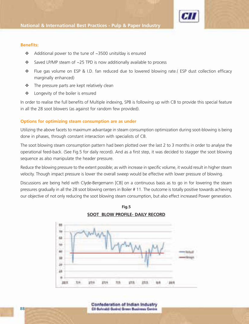
National & International Best Practices - Pulp & Paper Industry
88
Benefits:
� Additional power to the tune of ~3500 units/day is ensured
� Saved LP/MP steam of ~25 TPD is now additionally available to process
� Flue gas volume on ESP & I.D. fan reduced due to lowered blowing rate.( ESP dust collection efficacy
marginally enhanced)
� The pressure parts are kept relatively clean
� Longevity of the boiler is ensured
In order to realise the full benefits of Multiple indexing, SPB is following up with CB to provide this special feature
in all the 28 soot blowers (as against for random few provided).
Options for optimizing steam consumption are as under
Utilizing the above facets to maximum advantage in steam consumption optimization during soot-blowing is being
done in phases, through constant interaction with specialists of CB.
The soot blowing steam consumption pattern had been plotted over the last 2 to 3 months in order to analyse the
operational feed-back. (See Fig.5 for daily record). And as a first step, it was decided to stagger the soot blowing
sequence as also manipulate the header pressure.
Reduce the blowing pressure to the extent possible; as with increase in specific volume, it would result in higher steam
velocity. Though impact pressure is lower the overall sweep would be effective with lower pressure of blowing.
Discussions are being held with Clyde-Bergemann [CB] on a continuous basis as to go in for lowering the steam
pressures gradually in all the 28 soot blowing centers in Boiler # 11. The outcome is totally positive towards achieving
our objective of not only reducing the soot blowing steam consumption, but also effect increased Power generation.
Fig.5
SOOT BLOW PROFILE- DAILY RECORD

89
“Making Indian Pulp & Paper Industry World Class”
Table-1
Average SB Max. SB Steam HP Steam LP Steam
MonthSteam consumption saving Power available
consumption (Tons/Day) (Tons/Day) (Units/Day) (Tons/Day)(Tons/day)
April 66 75 Basis Basis Basis
May 48 64 18 2100 18
June 46 53 20 2350 20
Replication Potential
The above scheme can be extended to all the co-generating chemical recovery boilers which will result in additional
power and steam for the process.
Scope for Further Improvement
Now plans are underway to go in for MP steam extraction from the 16 MW Back pressure steam turbine for soot
blowing which will result in further enhancement of power ( by 0.2 MW) and additional steam generation of
1½ TPH for process.
With optimization as of above, the daily steam consumption for soot blowing had been brought down significantly,
as can be seen from the Summary as under (Refer Table-1).
Design soot blow = 37.4 Tons/day Year: 2009

National & International Best Practices - Pulp & Paper Industry
90
Process flow Diagram
Company Profile
Emami Paper Mills Ltd. has two paper mills Unit # 1 at Balasore and Unit # 2 at Kolkata. The Balasore mill was
expanded by installing a Newsprint Paper Machine (PM #3) production line, with all the auxiliaries and utilities.
Including this project the total installed capacity of EMAMI is 450 tpd (400 tpd in Balasore and 50 tpd in Kolkata).
Emami, Balasore has imported high efficiency screw press, it produces 55% dry sludge which is being feed directly
to the power boiler. It is replacing coal in the ration 2.3:1 i.e 2.3 ton of sludge is replacing 1 ton of coal. Emami,
Balasore is the first plant in India to implement this project of feeding De-inking Plant (DIP) sludge to Power Boiler.
Emami has also won an award from IPMA for this project.
Best Practices No. 5
Using Dip Sludge as Fuel Substitute for Power Boiler (Emami)
Unit : Emami Paper Mills (EMAMI), Balasore
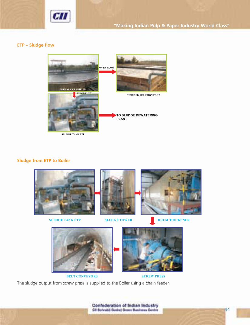
91
“Making Indian Pulp & Paper Industry World Class”
Sludge from ETP to Boiler
The sludge output from screw press is supplied to the Boiler using a chain feeder.
ETP – Sludge flow
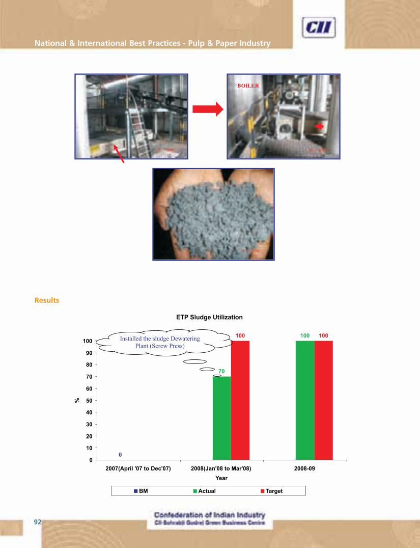
National & International Best Practices - Pulp & Paper Industry
92
Results
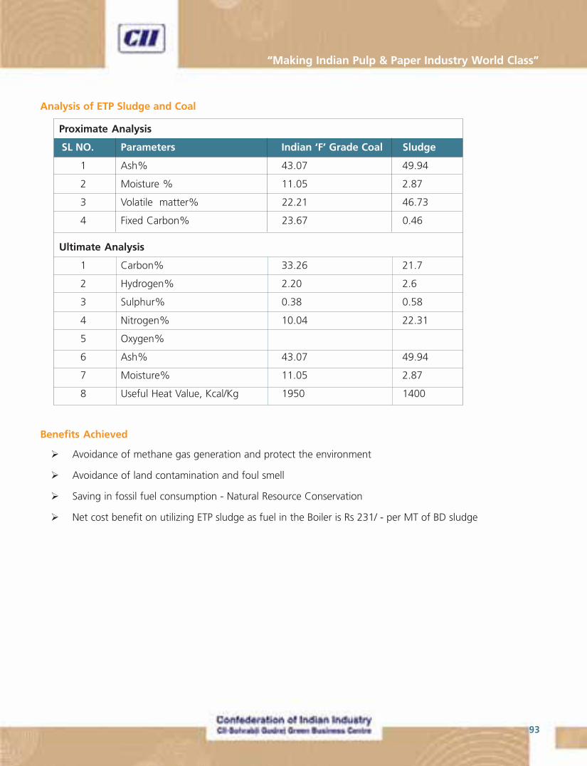
93
“Making Indian Pulp & Paper Industry World Class”
Benefits Achieved
� Avoidance of methane gas generation and protect the environment
� Avoidance of land contamination and foul smell
� Saving in fossil fuel consumption - Natural Resource Conservation
� Net cost benefit on utilizing ETP sludge as fuel in the Boiler is Rs 231/ - per MT of BD sludge
Analysis of ETP Sludge and Coal
Proximate Analysis
SL NO. Parameters Indian ‘F’ Grade Coal Sludge
1 Ash% 43.07 49.94
2 Moisture % 11.05 2.87
3 Volatile matter% 22.21 46.73
4 Fixed Carbon% 23.67 0.46
Ultimate Analysis
1 Carbon% 33.26 21.7
2 Hydrogen% 2.20 2.6
3 Sulphur% 0.38 0.58
4 Nitrogen% 10.04 22.31
5 Oxygen%
6 Ash% 43.07 49.94
7 Moisture% 11.05 2.87
8 Useful Heat Value, Kcal/Kg 1950 1400
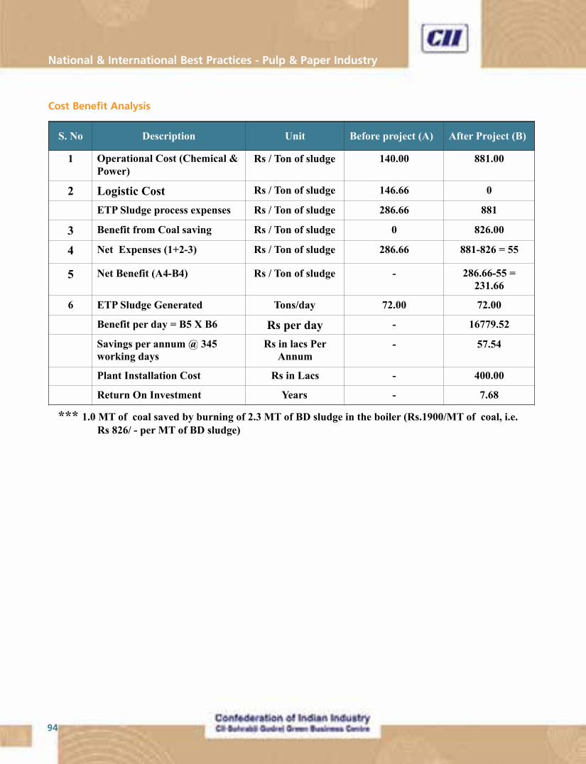
National & International Best Practices - Pulp & Paper Industry
94
Cost Benefit Analysis
95
“Making Indian Pulp & Paper Industry World Class”
Best Practices No. 6
Chloride Removal from Recovery Cycle – a Low Cost Option
Unit : TamilNadu Newsprint & Papers Ltd., Kagithapuram
Introduction
Tamilnadu Newsprint and Papers Ltd (TNPL) is one of the leading manufacturers of Newsprint and Printing and
writing paper in India and it operates an integrated pulp and paper mill with a production capacity of 2,45,000
tons per annum. The mill operates one recovery boiler with a firing capacity of 1300 TPD per day at 65 kg/cm2
pressure with a steam generation of 197.5 TPH. The recovery boiler fires liquor at 70% solids.
The mill was operating two recovery boilers and it was observed that the performance of the recovery boilers started
reducing and frequent cleaning of the flue gas passages was required leading to production losses. On a detailed
study of the problem, it was noted that the flue gas passages were blocked due to increase of chloride levels in the
system. The main problems due to higher levels of chlorides and potassium in the liquor cycle of chemical recovery
area were corrosion and plugging of the flue gas passages in the recovery boiler. This is due to the decrease in the
melting temperature of the deposits on the tubes with the increasing levels of chloride and potassium.
Sources of NPEs (Non-Process Elements)
The increase in chlorides was mainly due to the in-coming process water which has a chloride content varying from
100 ppm to 300 ppm and usage of un-debarked casuarina wood. Also since 2004, the mill has started using
treated effluent water which consist high level of chlorides in the process and the chloride level increased due to
the closure of water system in the mill as only a part quantity of water was discharged.
Methods adopted for removing NPE’s
Apart from chlorides, large number of non-process elements (NPE) like Al (Aluminium), Si (Silica), K (Potassium)
enters into the pulp mill mainly through raw material. The elements of concern are primarily those that don’t form
insoluble inorganic compounds in alkaline solutions i.e Al, Si, Cl (Chloride) and K. Transition elements like Mn
(Manganese), Cu (Copper) and the alkaline earth metals like Ca (Calcium) and Ba (Barium) also have to be handled
in an appropriate manner. The NPE, soluble in weak alkaline solutions are removed through PH adjustment by
addition of lime mud, lime or some other alkaline source. These NPEs are precipitated as insoluble inorganic
compounds which can be separated by filtration and purged from the system together with green liquor dregs.
Besides the existing systems like equipment for removing green liquor dregs, lime mud, ESP ash dust and bleach
plant effluents for purging the NPE’s, there is need for new systems to remove NPE’s to avoid problems arising from
the accumulation of these elements in a closed cycle Kraft pulp mill.
Traditionally recovery boiler ESP ash is discharged when there is need to purge chlorides and potassium from the
system. This had an adverse impact on the environment apart from causing added expense of soda make up.
National & International Best Practices - Pulp & Paper Industry
96
TNPL Scenario
Chlorides in white liquor is about 24 – 28 gpl as NaCl and Chlorides in Recovery boiler ESP ash is about 24 - 28%
as NaCl. Initially the chloride level was about 4-6% and got increased gradually to 10% and then to 20% and
presently to a level of 24-28%. The reason for the build up of chlorides is mainly the increased chloride content in
the incoming water which was contaminated with dying unit effluents in upstream of river. The other reason being
the recycling of treated effluent for the process in certain areas like bagasse washing.
TNPL‘s attempt to remove NPE’s (Cl and K)
Initially, it was proposed to maintain the chloride level by purging the ESP Ash. However owing to the environmental
impact of purging ESP ash, alternative methods were studied for removal of chlorides from the system.
Laboratory studies on the separation of chloride from sulphates.
From the literature it was observed that the solubility of chlorides differs much against that of sulphates in water.
Sodium chloride dissolved readily in water and also suppresses the solubility of sulphates. Laboratory studies were
conducted using the above principle to separate chlorides and sulphates.
A series of tests with varying amounts of ESP ash in water viz 500, 600, 800, 1000 and 1200 gram per liter were
prepared. The slurry is filtered. Both the cake and filtrate were analyzed for sodium sulphate, sodium chloride and
potassium.
ESP ash Analysis
Insolubles in water 0.11%
Sulphates as Na2SO4 70.3%
Chlorides as NaCl 24.2%
Potassium as K 5.10%
Carbonates as Na2CO3 0.30%
Cake analysis
ESP ash in water, gpl 50 600 800 1000 1200
Na2SO4, % 92.9 94.3 92.3 90.8 89.7
NaCl, % 1.87 2.45 3.84 5.14 6.43
Potassium as K, % 0.54 1.35 2.24 2.99 3.29
Sulphate recovery, % 12.0 34.2 60.6 79.1 89.1
Chloride removal, % 99.3 97.4 92.7 87.0 81.4
Potassium removal, % 99.0 93.3 79.7 64.1 54.9

97
“Making Indian Pulp & Paper Industry World Class”
ESP ash in water, gpl 500 600 800 1000 1200
Na2SO4, gpl 284.5 244.2 238.1 189.0 144.5
NaCl, gpl 109.6 131.5 157.8 197.3 236.7
Potassium as K, gpl 18.1 25.0 28.1 30.6 29.4
Filtrate Analysis
Encouraged by the results, a system was designed in TNPL where slurry of ESP Ash in water at about 800 gpl to
1000 gpl is fed into a decanter centrifuge which separates undissolved sodium sulphate as a cake from slurry. The
separated sodium sulphate is fed to mixing tank of recovery boiler and the filtrate rich in chlorides and potassium
is drained.
Components of the system
The system (see fig 1) consist of a tank with a capacity of 2 m3 with a slow speed agitator, a centrifugal pump, a
decanter centrifuge with feed rate, Density control equipments and necessary instrumentation.
Process description
The ash from ESP is fed to the tank and dissolved in water. Necessary feed consistency is maintained in the tank by
the density control instruments. The mixture at 800 to 1000 gpl is fed into the decanter centrifuge. The decanter
separates the sulfates in the form of cake/sludge. The centrifuged sludge with sodium sulfate is fed to the mixing
tank of recovery boiler. The filtrate rich with chlorides and potassium is drained.
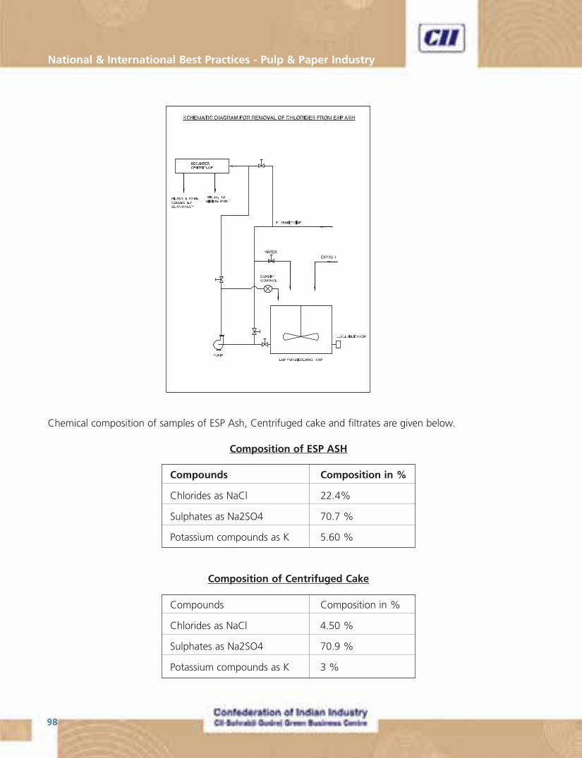
National & International Best Practices - Pulp & Paper Industry
98
Chemical composition of samples of ESP Ash, Centrifuged cake and filtrates are given below.
Composition of ESP ASH
Compounds Composition in %
Chlorides as NaCl 22.4%
Sulphates as Na2SO4 70.7 %
Potassium compounds as K 5.60 %
Composition of Centrifuged Cake
Compounds Composition in %
Chlorides as NaCl 4.50 %
Sulphates as Na2SO4 70.9 %
Potassium compounds as K 3 %
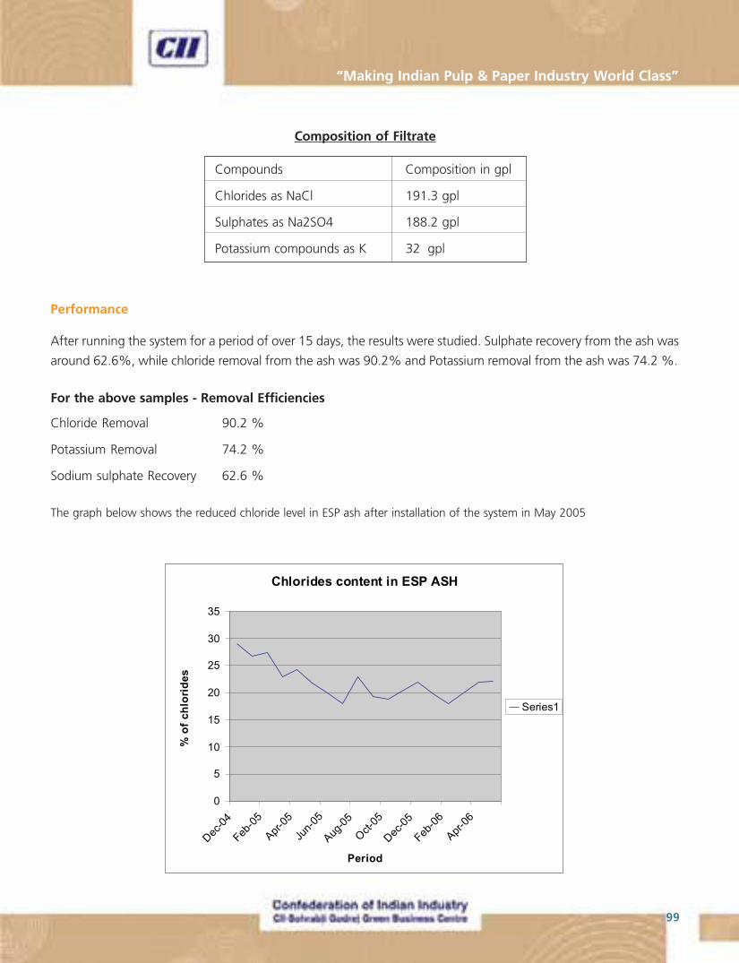
99
“Making Indian Pulp & Paper Industry World Class”
Composition of Filtrate
Compounds Composition in gpl
Chlorides as NaCl 191.3 gpl
Sulphates as Na2SO4 188.2 gpl
Potassium compounds as K 32 gpl
Performance
After running the system for a period of over 15 days, the results were studied. Sulphate recovery from the ash was
around 62.6%, while chloride removal from the ash was 90.2% and Potassium removal from the ash was 74.2 %.
For the above samples - Removal Efficiencies
Chloride Removal 90.2 %
Potassium Removal 74.2 %
Sodium sulphate Recovery 62.6 %
The graph below shows the reduced chloride level in ESP ash after installation of the system in May 2005
National & International Best Practices - Pulp & Paper Industry
100
Benefits of chloride removal by the system
� Increased stability of mill operation with less frequent stoppages of boiler for washing
� A reduction of corrosion in the recovery boiler
� An increase of recovery boiler steam production
Equipment specification
Decanter centrifuge
Make ALFA LAVAL INDIA LIMTED
Type : ALDEC
Design code : NX 414
Capacity : 2 m3/hr Feed rate.
Centrifugal pump
Flow : 5 m3/hr
Head : 30 m WC
Financials
Cost of the total project was 25 Lakhs.
Conclusion
Though the operation of the system helps to contain the level of chlorides in the system, as the filtrate which is
drained contains un-recovered sodium sulphate and chlorides, it increases the sodium content of the discharge
effluent. Pilot plant studies are conducted to treat this filtrate with WTP softener plant effluent rich in Na, Ca and
Mg Chlorides. By adding burnt lime, 67% Sulphates can be precipitated as CaSO4 and 100% Mg can be precipitated
as Mg(OH)2. After removing these precipitates, the filtrate containing mainly sodium chlorides can be sent to WTP
softener plant for regeneration of resin.

101
“Making Indian Pulp & Paper Industry World Class”
Benefits
� Effective Cl removal
� Effective K removal
� Effective Na2SO4 recovery
Chlorine Remover – In brief
Chlorine removal is based on dissolving and recrystallization of recovery boiler fly ash. A part of fly ash from
electrostatic precipitator is dissolved in a separate dissolving tank to warm liquid (e.g. warm water or secondary
condensate). From dissolving tank the solution is pumped to a pump tank and further to the recrystallizer.
During the recrystallization chloride remains in the solution, due to its higher solubility, while sodium sulfate and
carbonate crystallizes. These crystals are then removed from the solution and are delivered back to the chemical
cycle. The solution is led further to another recrystallizer which crystallizes chloride and potassium from the solution.
Chloride and potassium crystals are then discharged as moist cake.
A typical ARC system is a stand alone two stage evaporator/crystallizer system with forced circulation evaporator/
crystallizer units.
National & International Best Practices - Pulp & Paper Industry
102
Best Practices No. 7
Impact of Medium Consistency ECF Sequence on Water Consumption andPollution Load in TNPL
Unit : Tamil Nadu Newsprint and Papers Ltd., Kagithapuram
Introduction
The pulp and paper industry is one of the highest water consumers among major industries. Because, using a well-
diluted fiber suspension for manufacturing paper on wire is still the same from the day paper was invented 2000
years ago. The water is used in the mills; a major fraction becomes contaminated with pollutants generated during
various processes of pulp and paper manufacturing. This contaminated water has to be treated and discharged
later as effluent. Another important fraction of the collected water is lost, it does not return back to the water or
wastewater stream. These losses are due to evaporation, losses to the ground, water carried along with solid
wastes and finished products as moisture, etc. In 80’s water consumption per ton of paper produced was as high
as 250 m³/MT, and even at present it ranges from 100 to 150 m3/ MT because the water has been an inexpensive
material to the industry. The total water cost has only been calculated by the sum of the costs for collection,
treatment and distribution. It is obvious that this situation has to change, and it is because, there is also a very
interesting physics law by the well-known Lavoisier’s law for the mass conservation in the system “what comes in
has to go out”. More water a mill uses, more effluent it will generate. It is then obvious that more water we use,
higher are our costs, both in water and for effluents.
The reason for high water consumption is simple: more water a mill uses, cleaner are the pulp and the processes.
The water removes unwelcome contaminants, those that may cause dirt in the pulp, difficulties in bleaching, and
incrustations and plugging in the process. Colloids, mineral ions, chromophoric groups, wood extractives, organic
radicals, slime, stickies, and a lot more, may be eliminated from the process through the water. Good to the process
but bad to the environment. When water systems are closed and water consumption minimized, these contaminants
may cause problems as production and final product quality losses. For these reasons, the pulp and paper mills
would prefer to work in open water cycles. That is the one high significant for water consumption and it ranges as
high as 100 to 150 m³/ MT of paper even though when technologies are available to manufacture white paper
with bout 40 to 50 m³ per ton of paper. Something it is unacceptable according to today’s growing environments
awareness and standards. Mills have closed their water circuits and they are generating less effluent using modern
pulp and paper technologies. Today, the bleached kraft pulp manufacture is reporting values from 40 to 50 m³/ ton
of white paper. Apart from water CESS paid to government, mills spending enormous sums of capital in the
construction of huge water and wastewater treatment plants and subsequent revenue expenditure to run and
maintain the plants. Reduction in the water consumption leads to considerable saving in the above areas. Now our
focus should be on designing a system to prevent pollutants at source, to recycle wastewater with in the plant and
to segregate good water from wastewater, instead of using end-of-pipe techniques.
103
“Making Indian Pulp & Paper Industry World Class”
Tamilnadu Newsprint and Papers Limited (TNPL), a Government of Tamilnadu Enterprise, owns and successfully
operates India’s largest bagasse based Integrated Pulp and Paper mill, having an installed capacity of 245,000 TPA
of Newsprint and Printing & Writing paper. The mill had two streets of continuous Kraft chemical bagasse fibreline
of total 380 TPD with CEpH bleaching and one 120 TPD kraft batch hardwood chemical fibre line with CEPHH
bleaching. Under the Mill Development Plan (MDP), TNPL had replaced 120 TPD Hardwood fibreline with 330 TPD
Superbatch cooking system with oxygen delignification process with DHT EOP D medium consistency bleaching
sequence and complete brown loop closure. The chemical bagasse line was integrated in to single line 500 TPD ECF
(DHT EOP D) medium consistency bleaching. The oxygen delignification and brown loop closer is under way in the
bagasse line under mill expansion plan. MDP was implemented in the year 2008 and it became fully functional in
the year 2009. Impact of the implementation of above measure under the MDP with respect to water consumption
and associated pollution load to the wastewater treatment has been compared and discussed with data collected
before and after implementation of MDP.
Results and discussions
Water is the medium where all the pulp and paper making process are carried out and it is also used as vehicle to
transport the pulp in the mills from one place to another place. Historically, the pulp is transferred by low consistency
pumping (2.5 to 3.5%). This means that for each dry ton of pulp, we are also pumping 96 to 97 m³ of water. In this
process the water gets several contaminants like, colloids, ions, fines, pitch, chromophoric groups, sand, volatile
odorous compounds (VOCs), toxic compounds (AOX), that enter to the other area together with the pulp. Therefore,
we should move to other concepts that are very important for improving our processes. High consistency washers
would surely reduce water and energy consumption for each dry ton of pulp produced which is great to environment.
Implementation medium consistency process in the new hard wood line and in new ECF bleaching process is one
of the major element which reduced the water consumption level in the pulp mill. The average water consumption
per day in the pulp mill reduced from 44,092 m3 from 2007 to 25,528 m3 in 2009. (FIGURE -1). Though, the overall
consumption of water reduced in the pulp mill by 42%, the use of soft water increased considerably (37.6%) to
avoid the scaling problem. As expected the average consumption did not reduce in other areas like paper machine,
utilities, SRP and energy side and the reduction is only 9% (FIGURE - 2). However, overall water consumption in the
mill has reduced significantly from 70,851 in the year 2007 to 49,944 in the year 2009, because, the pulp mill is the
major consumer of water in the mill. From FIGURE – 3, it is clear that the average water consumption per day has
reduced by 30% in 2009 when compared to 2007 and specific consumption per ton of product is 99 m3, 87 m3,
74 m3 and 61 m3 for 2007, 2008, 2009 and May 2009 respectively (Figure - 8).
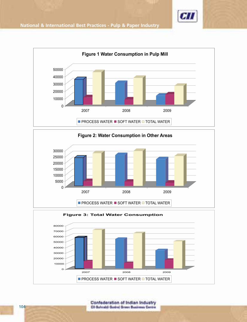
National & International Best Practices - Pulp & Paper Industry
104
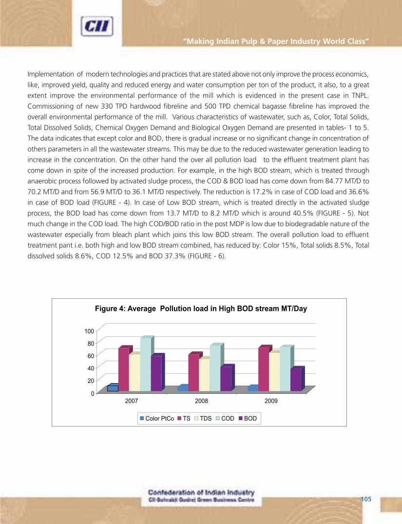
105
“Making Indian Pulp & Paper Industry World Class”
Implementation of modern technologies and practices that are stated above not only improve the process economics,
like, improved yield, quality and reduced energy and water consumption per ton of the product, it also, to a great
extent improve the environmental performance of the mill which is evidenced in the present case in TNPL.
Commissioning of new 330 TPD hardwood fibreline and 500 TPD chemical bagasse fibreline has improved the
overall environmental performance of the mill. Various characteristics of wastewater, such as, Color, Total Solids,
Total Dissolved Solids, Chemical Oxygen Demand and Biological Oxygen Demand are presented in tables- 1 to 5.
The data indicates that except color and BOD, there is gradual increase or no significant change in concentration of
others parameters in all the wastewater streams. This may be due to the reduced wastewater generation leading to
increase in the concentration. On the other hand the over all pollution load to the effluent treatment plant has
come down in spite of the increased production. For example, in the high BOD stream, which is treated through
anaerobic process followed by activated sludge process, the COD & BOD load has come down from 84.77 MT/D to
70.2 MT/D and from 56.9 MT/D to 36.1 MT/D respectively. The reduction is 17.2% in case of COD load and 36.6%
in case of BOD load (FIGURE - 4). In case of Low BOD stream, which is treated directly in the activated sludge
process, the BOD load has come down from 13.7 MT/D to 8.2 MT/D which is around 40.5% (FIGURE - 5). Not
much change in the COD load. The high COD/BOD ratio in the post MDP is low due to biodegradable nature of the
wastewater especially from bleach plant which joins this low BOD stream. The overall pollution load to effluent
treatment pant i.e. both high and low BOD stream combined, has reduced by: Color 15%, Total solids 8.5%, Total
dissolved solids 8.6%, COD 12.5% and BOD 37.3% (FIGURE - 6).
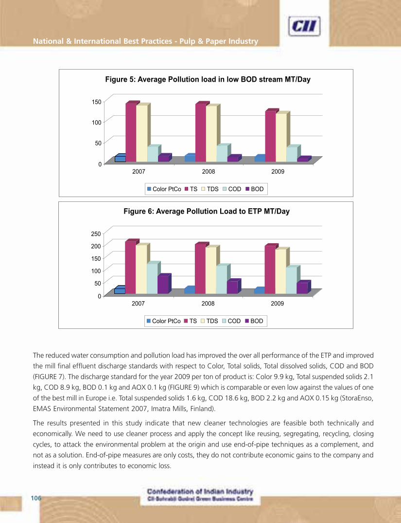
National & International Best Practices - Pulp & Paper Industry
106
The reduced water consumption and pollution load has improved the over all performance of the ETP and improved
the mill final effluent discharge standards with respect to Color, Total solids, Total dissolved solids, COD and BOD
(FIGURE 7). The discharge standard for the year 2009 per ton of product is: Color 9.9 kg, Total suspended solids 2.1
kg, COD 8.9 kg, BOD 0.1 kg and AOX 0.1 kg (FIGURE 9) which is comparable or even low against the values of one
of the best mill in Europe i.e. Total suspended solids 1.6 kg, COD 18.6 kg, BOD 2.2 kg and AOX 0.15 kg (StoraEnso,
EMAS Environmental Statement 2007, Imatra Mills, Finland).
The results presented in this study indicate that new cleaner technologies are feasible both technically and
economically. We need to use cleaner process and apply the concept like reusing, segregating, recycling, closing
cycles, to attack the environmental problem at the origin and use end-of-pipe techniques as a complement, and
not as a solution. End-of-pipe measures are only costs, they do not contribute economic gains to the company and
instead it is only contributes to economic loss.
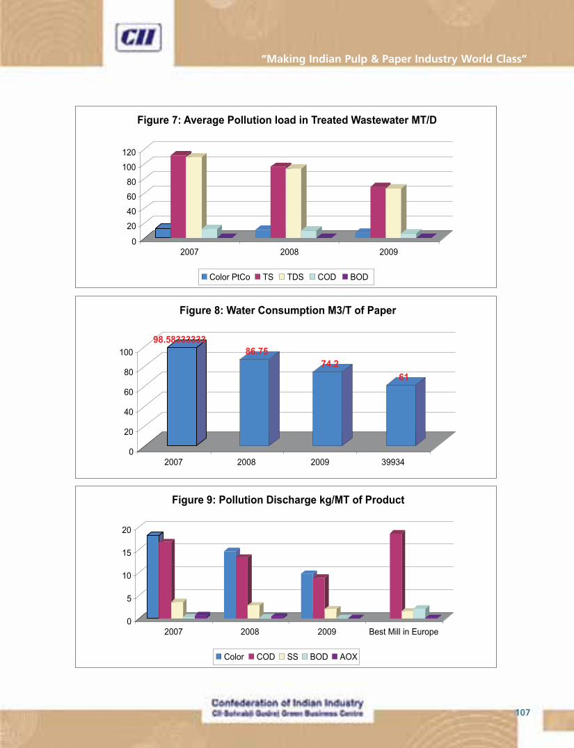
107
“Making Indian Pulp & Paper Industry World Class”
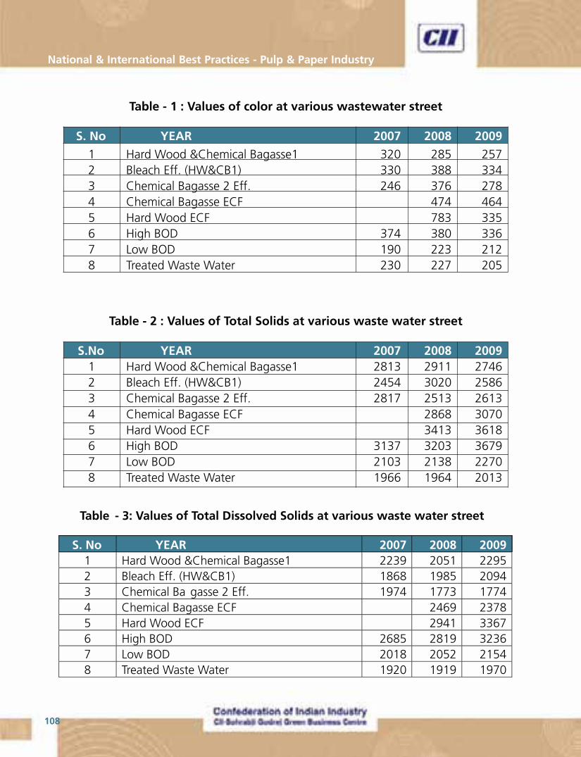
National & International Best Practices - Pulp & Paper Industry
108
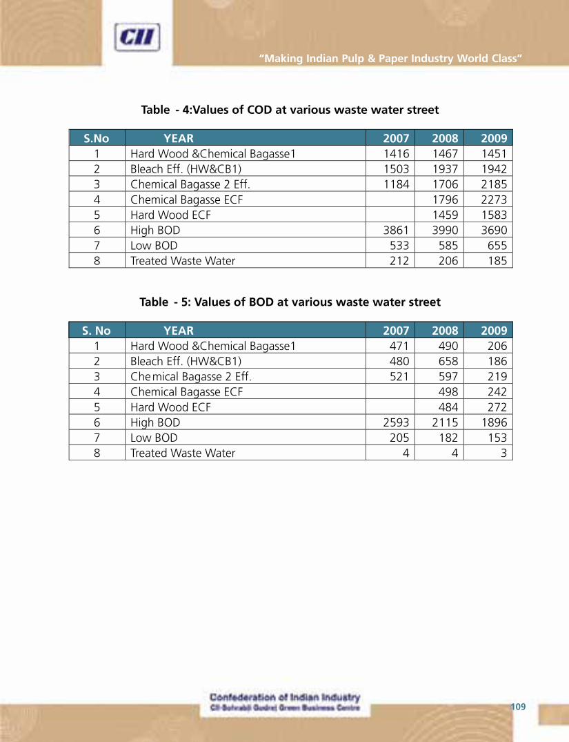
109
“Making Indian Pulp & Paper Industry World Class”
National & International Best Practices - Pulp & Paper Industry
110
Best Practices No. 8
Activated Sludge Process with MBBR Technology
Unit : ITC – PSPD, Bhadrachalam
Company Profile
ITC – PSPD, Bhadrachalam is one of the largest integrated pulping and paperboard manufacturing unit in India.
With a total manufacturing capacity of more than 3,50,000 tonnes of papers and paperboards per annum,
Bhadrachalam unit is a manufacturing site for some of the popular packaging and graphic application brands – like
Cyber XLPac,Cyber Cypak and Safire Graphik as well as our range of fine printing papers like Alfa Zap, HiBrite and
Alfa Plus. This mill has equipments supplied by internationally renowned suppliers for pulping processes, paper
machines, web detection & inspection systems, and finishing & packing lines. The facilities here consist of 6 machines,
of which 3 are paperboard machines. The Bhadrachalam unit is ISO 9001:2000 series accredited. The unit is also
ISO 14001 certified for Environment Management Systems.
Introduction
Paper industry effluent contains organic matter (BOD, COD, TOC), color, toxicity (acute, chronic), suspended material,
nutrients (N and P) and heavy metals.
Effluent treatment methods
� Mechanical Treatment - Separation of particles
� Chemical Treatment
� Biological Treatment
Mechanical treatment
Usually treats suspended, rather than dissolved pollutants by allowing suspended pollutants to settle out or float to
the top naturally– depending on whether they are more or less denser than water.
By gently stirring the water, more small particles will tend to bump into each other and stick together, forming
larger particles that will settle faster.
To aid flotation processes, dissolved air under pressure can be added to cause the formation of tiny bubbles that
will attach to particles.
111
“Making Indian Pulp & Paper Industry World Class”
Chemical Treatment
Removal of COD, metals and suspended solids can effectively be done by chemical treatment procedures. It can
also be used to remove ammonia, and other toxic pollutants like cyanides, organics, pesticides & herbicides.
Examples of Chemical Treatment are Flocculation of particles, precipitation of phosphorus and some dissolved
material with alum or other chemicals.
Biological treatment processes are based on the activity of micro-organisms transforming organic material in to
carbon dioxide, water and biomass.
Three basic processes in Biological Treatment are:
� Aerated lagoons
� Activated sludge
� Bio-film systems
Bio-film Systems or Moving Bed Bio Reactor (MBBR) Systems
What is bio-film?
Biofilm is a community of different microorganisms, and their extra-cellular products, attached to an “inert” surface.
Biofilms can be found on many different surfaces like Boat hulls, pipes, heat exchangers, electrodes, teeth, whitewater
system etc.
MBBR Technology
Treatment of effluent with microorganisms developed as bio-films on biochips in an aeration tank to reduce the
pollutant load (COD/BOD) in a Secondary Treatment process is called as Moving Bed Bio-film Technology.
Principle
The Process is based on the biofilm principle, and the core of the process is the biofilm carrier elements made from
polyethylene with a density slightly below that of water. These are designed to provide a large protected surface for
the, bacteria culture.
Because of providing large surface area via biochip, the micro organisms will not easily come out from the system
and they develop bio-films on the carrier element/biochip to easily degrade the organic material and to reduce the
pollutants (COD/BOD) load.
The biofilm carrier elements are being kept suspended in water by air from the diffusers in the aerobic reactors, and
by means of a mixer in the reactors.
National & International Best Practices - Pulp & Paper Industry
112
Advantages
� Robust towards variations and disturbances
� Can be operated at high organic loading rates
� Simple to operate, minimal need for control
The most important microorganisms in effluent treatment are Bacteria, Archaea, Micro animals & Fungi.
Microorganisms
Microorganisms are necessary for clarification and to filter water off the dispersed bacteria; these are more sensitive
than bacteria. Examples of Micro animals are
Protozoa (Unicellular animals)
� Flagellates
� Amoebas
� Ciliates ~10 – 300 ìm (free-swimming, crawling, stalked, suctoria)
Metazoa (Multi-cellular animals)
� Rotifers
� Nematodes
� Water Bears
� Worms
Factors affecting treatment are temperature, pH, toxicity, oxygen, nutrients organic material.
Optimal Growth Conditions
Organic load < design data, F/M for AS
Oxygen > ” 2 – 3 ppm (MBBR)
NH4 - N > 1 ppm
PO4 - P > 0.5 ppm
pH 6.5 – 8.5
Temperature < 38 ºC

113
“Making Indian Pulp & Paper Industry World Class”
Installation at ITC - Bhadrachalam
Treatment Facilities at ITC
� Mechanical pre-treatment - Bar screen and primary clarifier
� Biological treatment - Activated sludge , MBBR
� Post treatment - Clarifier (mechanical)
Process
The Overflow from Primary Clarifier (Colored effluents) is led to Moving Bed Bio-Reactor to reduce Soluble COD to
60%. The outlet of MBBR enters into Aeration tank for further reduction of organic matter and then to Secondary
Clarifier for reduction of suspended solids and other pollutant load.
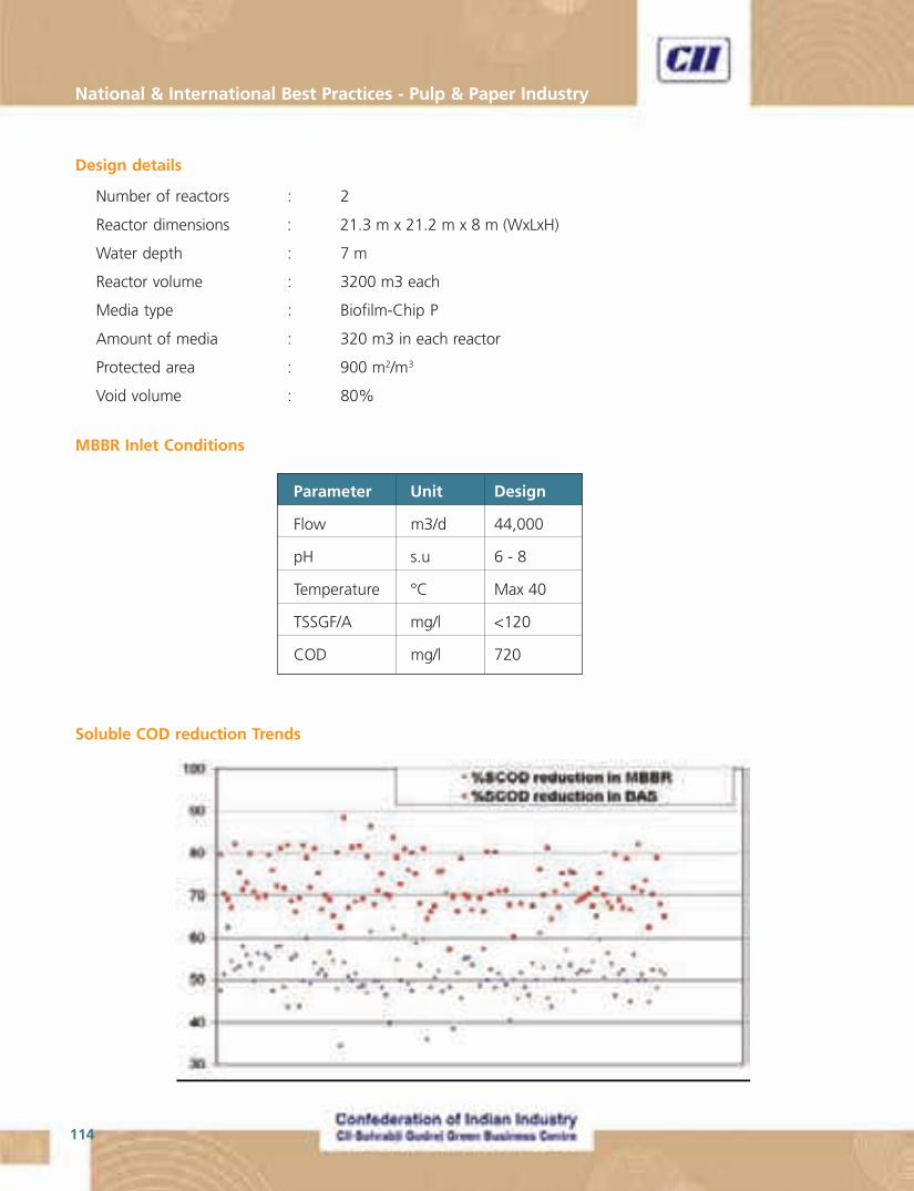
National & International Best Practices - Pulp & Paper Industry
114
Design details
Number of reactors : 2
Reactor dimensions : 21.3 m x 21.2 m x 8 m (WxLxH)
Water depth : 7 m
Reactor volume : 3200 m3 each
Media type : Biofilm-Chip P
Amount of media : 320 m3 in each reactor
Protected area : 900 m2/m3
Void volume : 80%
MBBR Inlet Conditions
Parameter Unit Design
Flow m3/d 44,000
pH s.u 6 - 8
Temperature °C Max 40
TSSGF/A mg/l <120
COD mg/l 720
Soluble COD reduction Trends
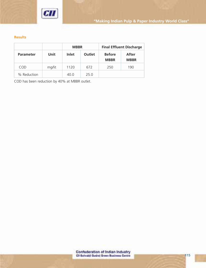
115
“Making Indian Pulp & Paper Industry World Class”
Results
MBBR Final Effluent Discharge
Parameter Unit Inlet Outlet Before After
MBBR MBBR
COD mg/lit 1120 672 250 190
% Reduction 40.0 25.0
COD has been reduction by 40% at MBBR outlet.
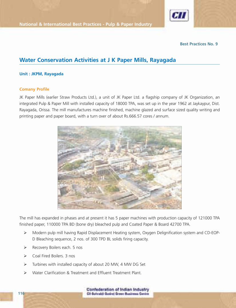
National & International Best Practices - Pulp & Paper Industry
116
Best Practices No. 9
Water Conservation Activities at J K Paper Mills, Rayagada
Unit : JKPM, Rayagada
Comany Profile
JK Paper Mills (earlier Straw Products Ltd.), a unit of JK Paper Ltd. a flagship company of JK Organization, an
integrated Pulp & Paper Mill with installed capacity of 18000 TPA, was set up in the year 1962 at Jaykaypur, Dist.
Rayagada, Orissa. The mill manufactures machine finished, machine glazed and surface sized quality writing and
printing paper and paper board, with a turn over of about Rs.666.57 cores / annum.
The mill has expanded in phases and at present it has 5 paper machines with production capacity of 121000 TPA
finished paper, 110000 TPA BD (bone dry) bleached pulp and Coated Paper & Board 42700 TPA.
� Modern pulp mill having Rapid Displacement Heating system, Oxygen Delignification system and CD-EOP-
D Bleaching sequence, 2 nos. of 300 TPD BL solids firing capacity.
� Recovery Boilers each. 5 nos
� Coal Fired Boilers. 3 nos
� Turbines with installed capacity of about 20 MW, 4 MW DG Set
� Water Clarification & Treatment and Effluent Treatment Plant.
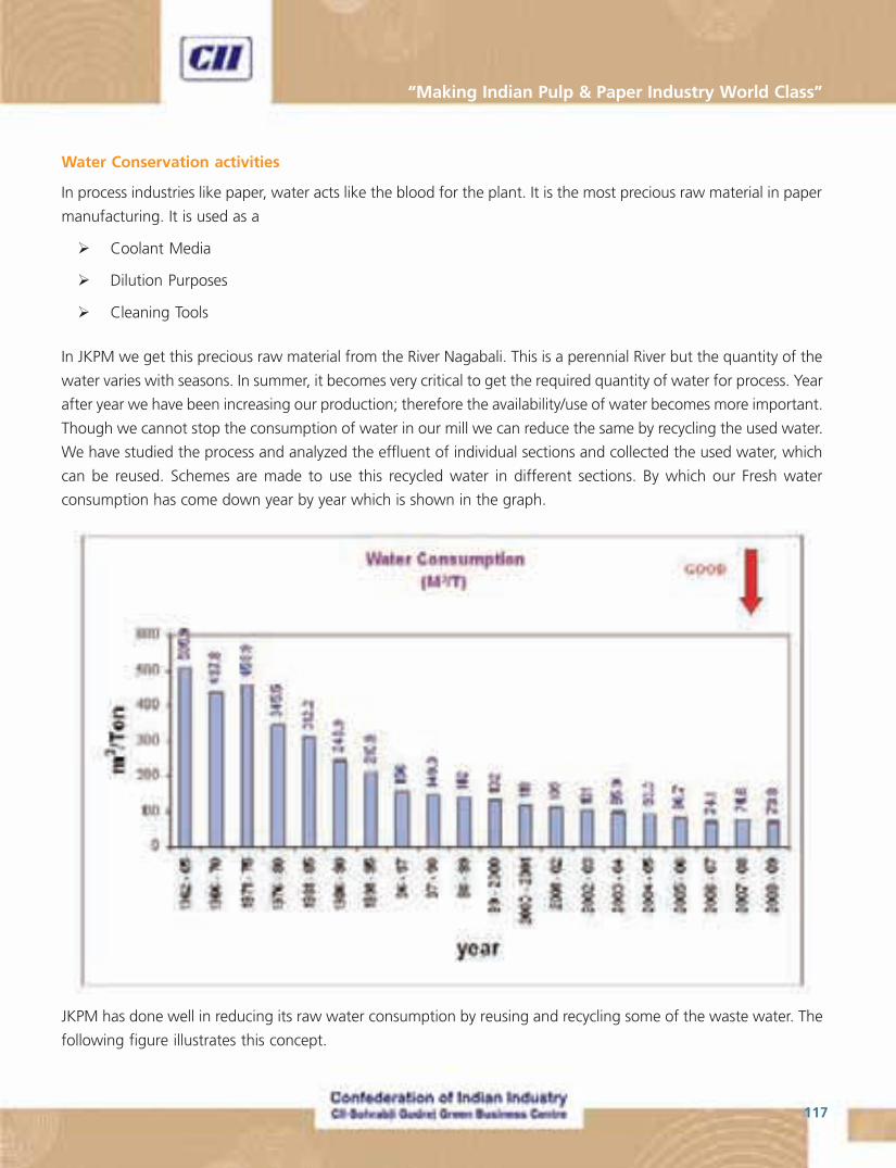
117
“Making Indian Pulp & Paper Industry World Class”
Water Conservation activities
In process industries like paper, water acts like the blood for the plant. It is the most precious raw material in paper
manufacturing. It is used as a
� Coolant Media
� Dilution Purposes
� Cleaning Tools
In JKPM we get this precious raw material from the River Nagabali. This is a perennial River but the quantity of the
water varies with seasons. In summer, it becomes very critical to get the required quantity of water for process. Year
after year we have been increasing our production; therefore the availability/use of water becomes more important.
Though we cannot stop the consumption of water in our mill we can reduce the same by recycling the used water.
We have studied the process and analyzed the effluent of individual sections and collected the used water, which
can be reused. Schemes are made to use this recycled water in different sections. By which our Fresh water
consumption has come down year by year which is shown in the graph.
JKPM has done well in reducing its raw water consumption by reusing and recycling some of the waste water. The
following figure illustrates this concept.

National & International Best Practices - Pulp & Paper Industry
118
One key factor that adds success to the efforts of JKPM towards water conservation is the formation of a core team
working responsible for water conservation. This team at JKPM is called “Water Conservation Committee”, WCM
in short.
Water Conservation Committee
Chairman : CGM (Eng.)
Coordinator : GM (PB)
Members : 5 Nos. Representing all
Process sections
Schedule meeting : Once Every Month
Management Review : i) Monthly Performance meeting
ii) ISO & OSHAS Review every 3months
iii) TPM SHE Pillar Presentation & review by TPM consultant
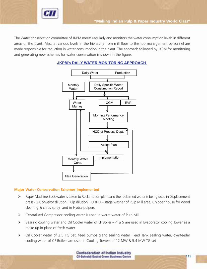
119
“Making Indian Pulp & Paper Industry World Class”
The Water conservation committee of JKPM meets regularly and monitors the water consumption levels in different
areas of the plant. Also, at various levels in the hierarchy from mill floor to the top management personnel are
made responsible for reduction in water consumption in the plant. The approach followed by JKPM for monitoring
and generating new schemes for water conservation is shown in the figure.
Major Water Conservation Schemes Implemented
� Paper Machine Back water is taken to Reclamation plant and the reclaimed water is being used in Displacement
press - 2 Conveyor dilution, Pulp dilution, PO & D – stage washer of Pulp Mill area, Chipper house for wood
cleaning & chips spray and in Hydra-pulpers
� Centralised Compressor cooling water is used in warm water of Pulp Mill
� Bearing cooling water and Oil Cooler water of LF Boiler – 4 & 5 are used in Evaporator cooling Tower as a
make up in place of fresh water
� Oil Cooler water of 2.5 TG Set, feed pumps gland sealing water ,Feed Tank sealing water, overfeeder
cooling water of CF Boilers are used in Cooling Towers of 12 MW & 5.4 MW TG set

National & International Best Practices - Pulp & Paper Industry
120
� CF Boiler coal spreader bearing cooling water is used in ash quenching in stead of fresh water
� Bearing cooling water of pope reel, cooling cylinder, edge cutter tank overflows, heat exchanger cooling
water & flash steam from condensate tanks are taken in warm water tank of respective machines which are
again reused in wire, felt showers and starch preparation
� Fibre recovery system from back waters is made in all machines like ADKA in PM/c-1 & 2, Wagner Filter is
PM/c -3, Krofta save all in PM/c-4, Mark save all in Pm/c-5 so that after fibre recovery the water is called as
clarified water .This clarified water is again used in Broke Pulpers of respective Machines and in stock
preparation
Further more Water conservation schemes are under study which will reduce the specific water
Consumption from 74 m3/T to 65 m3/T of Paper. Again JKPM plans for zero discharge by using effluent for
irrigation purpose and further study is under progress to reuse the effluent in the plant after de-colourisation by
enzyme treatment.
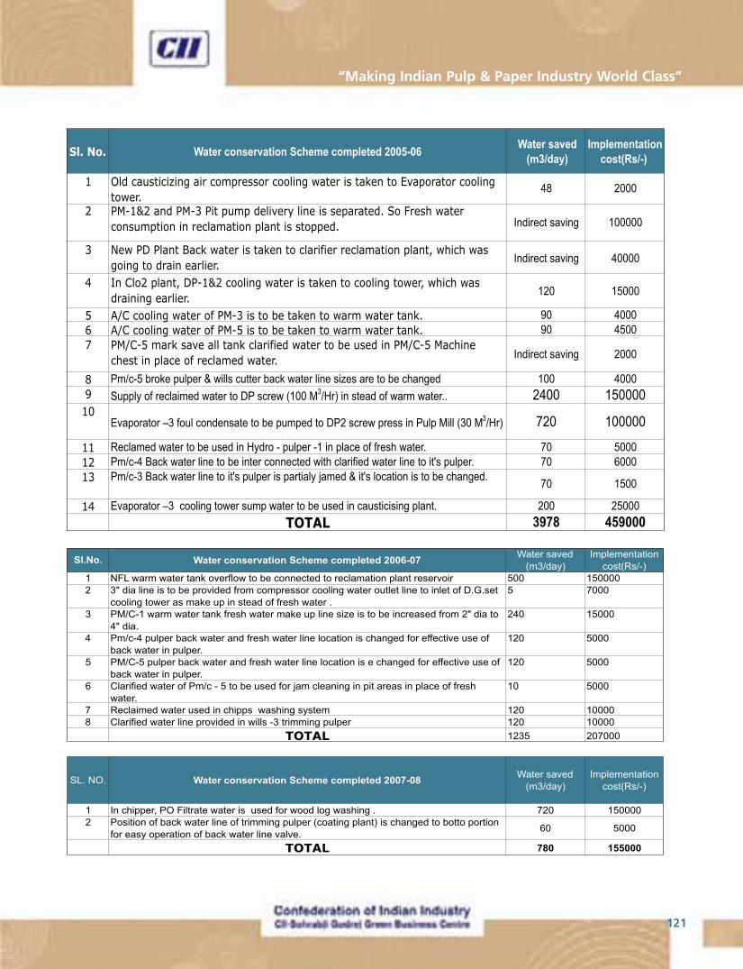
121
“Making Indian Pulp & Paper Industry World Class”
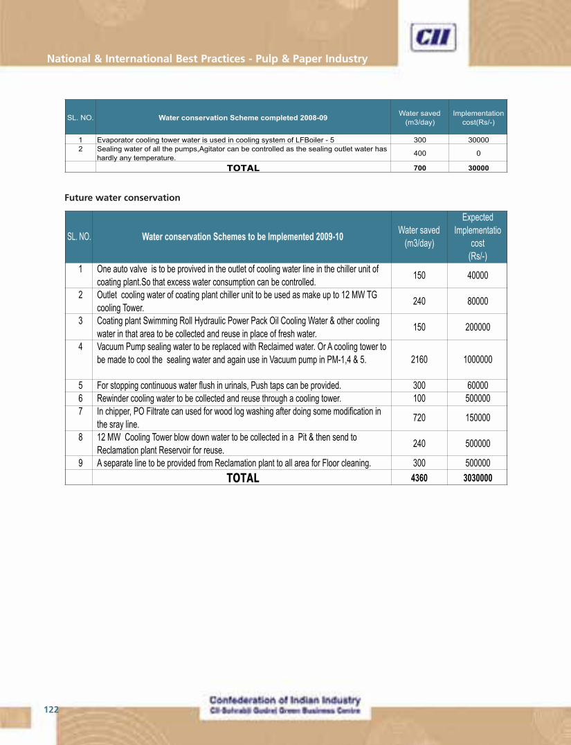
National & International Best Practices - Pulp & Paper Industry
122
123
“Making Indian Pulp & Paper Industry World Class”
Best Practices No. 10
Advanced Process Controllers installed in areas other than Pulp Mill
Unit : ITC - PSPD, Bhadrachalam
Introduction
After having successfully installed in the pulp mill, the advanced process controllers have been given a go for the
limekiln, Soda recovery boiler and the power block. The results are as follows.
Lime Kiln - 1
Problem
� Unable to reduce fluctuation of burning zone temperature due to long dead time associated in the process
between fuel oil flow and burning zone temperature
� Fluctuation in Burning zone temperature which is not an optimized operation results in more consumption
of fuel oil per ton of product (lime)
� Excess oxygen in flue gas being maintained on the higher side (> 5%)
Challenge
� Long dead time cannot be handled by DCS level PID controllers
� Fuel oil flow affecting both burning zone temperature and excess oxygen in flue gas which is a multivariable
problem and same cannot be addressed by basic level controllers
� Disturbance in the unit demands for frequent changes in the operating parameters to maintain the critical
operating parameters with good judgment
Solution/Advantages of APC
� Long dead time process can be effectively handled by model based Advanced Process Controller
� Multivariable control problems can be addressed
� Control is based on models which derived from actual plant test
� Have the advantage of predictability (Feed Forward)
� APC responds to disturbances in the plant and takes corrective action typically every minute around the
clock
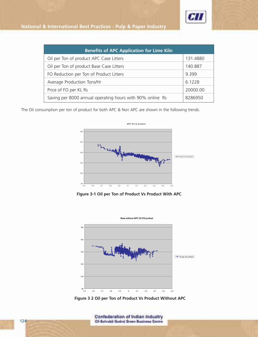
National & International Best Practices - Pulp & Paper Industry
124
The Oil consumption per ton of product for both APC & Non APC are shown in the following trends.
A PC O il vs product
8 0
10 0
12 0
14 0
16 0
18 0
5. 5 5 .6 5 .7 5.8 5 .9 6 6.1 6 .2 6. 3 6 .4 6 .5
Oil pe r to n p rod uct
Figure 3 2 Oil per Ton of Product Vs Product Without APC
Base without APC Oil VS product
80
100
120
140
160
180
5.5 5.6 5.7 5.8 5.9 6 6.1 6.2 6.3 6.4 6.5
Oil per ton product
Benefits of APC Application for Lime Kiln
Oil per Ton of product APC Case Litters 131.4880
Oil per Ton of product Base Case Litters 140.887
FO Reduction per Ton of Product Litters 9.399
Average Production Tons/Hr 6.1228
Price of FO per KL Rs 20000.00
Saving per 8000 annual operating hours with 90% online Rs 8286950
Figure 3-1 Oil per Ton of Product Vs Product With APC

125
“Making Indian Pulp & Paper Industry World Class”
O2 Comparision Base and APC CASE
0
2
4
6
8
10
12
1 202 403 604 805 1006 1207 1408 1609 1810 2011 2212 2413 2614 2815 3016 3217 3418 3619 3820 4021
FLUE GAS OXYGEN
Soda Recovery Boiler – 2
Problem
� Fluctuation in excess oxygen in flue gas.
� Excess oxygen in flue gas at higher side (>6%)
� Maintaining primary, secondary and tertiary air ratios as well as excess oxygen in flue gas which is a typical
multi-variable problem
� Improve Steam per Ton of Black liquor solids by optimizing the overall boiler operations
Challenge
� Multivariable control problem cannot be addressed by basic level controllers
� Lack of feed forward information for better control on excess oxygen
� Frequent disturbances in the unit demands for frequent control actions to maintain critical operating
parameters
Solution
� APC addresses the multivariable control problem to maintain both air ratios and excess oxygen in flue gas
� APC takes corrective actions every 30 seconds for disturbances in the unit to maintain excess oxygen close
to the minimum allowable limit
Figure 3.5 2 Flue gas Oxygen comparison of Base and APC cases
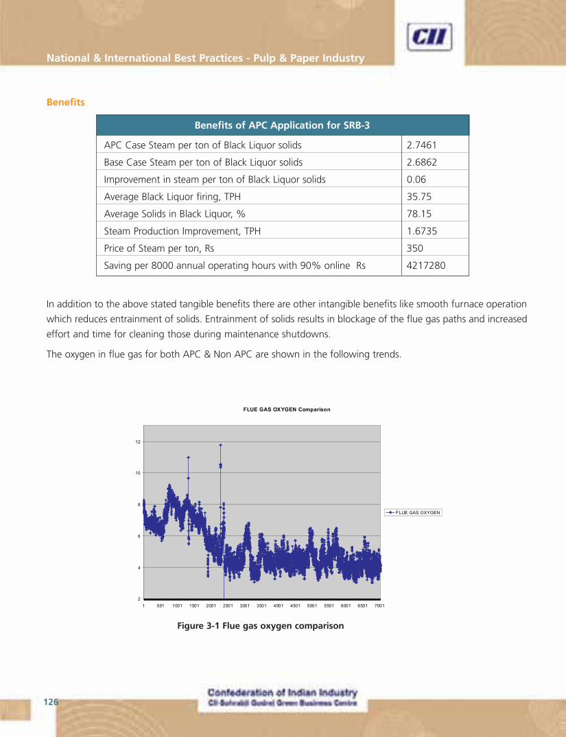
National & International Best Practices - Pulp & Paper Industry
126
Benefits
Benefits of APC Application for SRB-3
APC Case Steam per ton of Black Liquor solids 2.7461
Base Case Steam per ton of Black Liquor solids 2.6862
Improvement in steam per ton of Black Liquor solids 0.06
Average Black Liquor firing, TPH 35.75
Average Solids in Black Liquor, % 78.15
Steam Production Improvement, TPH 1.6735
Price of Steam per ton, Rs 350
Saving per 8000 annual operating hours with 90% online Rs 4217280
In addition to the above stated tangible benefits there are other intangible benefits like smooth furnace operation
which reduces entrainment of solids. Entrainment of solids results in blockage of the flue gas paths and increased
effort and time for cleaning those during maintenance shutdowns.
The oxygen in flue gas for both APC & Non APC are shown in the following trends.
FLUE GAS OXYGEN Comparison
2
4
6
8
10
12
1 501 1001 1501 2001 2501 3001 3501 4001 4501 5001 5501 6001 6501 7001
FLUE GAS OXYGEN
Figure 3-1 Flue gas oxygen comparison
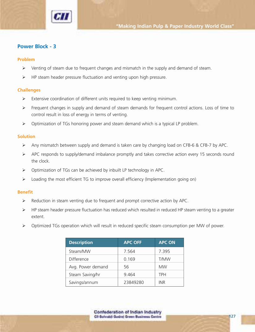
127
“Making Indian Pulp & Paper Industry World Class”
Power Block - 3
Problem
� Venting of steam due to frequent changes and mismatch in the supply and demand of steam.
� HP steam header pressure fluctuation and venting upon high pressure.
Challenges
� Extensive coordination of different units required to keep venting minimum.
� Frequent changes in supply and demand of steam demands for frequent control actions. Loss of time to
control result in loss of energy in terms of venting.
� Optimization of TGs honoring power and steam demand which is a typical LP problem.
Solution
� Any mismatch between supply and demand is taken care by changing load on CFB-6 & CFB-7 by APC.
� APC responds to supply/demand imbalance promptly and takes corrective action every 15 seconds round
the clock.
� Optimization of TGs can be achieved by inbuilt LP technology in APC.
� Loading the most efficient TG to improve overall efficiency (Implementation going on)
Benefit
� Reduction in steam venting due to frequent and prompt corrective action by APC.
� HP steam header pressure fluctuation has reduced which resulted in reduced HP steam venting to a greater
extent.
� Optimized TGs operation which will result in reduced specific steam consumption per MW of power.
Description APC OFF APC ON
Steam/MW 7.564 7.395
Difference 0.169 T/MW
Avg. Power demand 56 MW
Steam Saving/hr 9.464 TPH
Savings/annum 23849280 INR
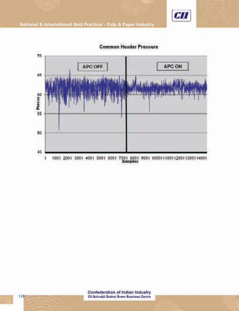
National & International Best Practices - Pulp & Paper Industry
128
129
“Making Indian Pulp & Paper Industry World Class”
ACTION PLAN & CONCLUSION
Action Plan
� The individual paper plants have to assess the present performance and should develop its own individual
target for improving parameters concerning energy, water and environmental performance
� Set and achieve voluntary target of at least 1 to 5% reduction in specific energy consumption every year
� The best practices and the performance improvement projects compiled in this manual may be considered
for implementation after suitably fine tuning to match the individual plant requirements
� If required, CII-Godrej GBC will help the individual units to improve the performance by providing energy
audit services and identifying performance improvement projects specific to individual units to achieve the
targets
� The present level of performance and the improvements made by the individual units have to be monitored
� The performance improvement of these units will be reviewed in the “Papertech” every year and the
information will be disseminated among the Indian Pulp and Paper plant
Conclusion
The objective of the project will be fulfilled only if the performance of all the pulp and paper units improves and
achieves world class standards.
We are sure that the Indian Pulp and Paper units will make use of this opportunity, improve their performance and
move towards the world class Energy Efficiency.

National & International Best Practices - Pulp & Paper Industry
130

131
“Making Indian Pulp & Paper Industry World Class”
Annexures

National & International Best Practices - Pulp & Paper Industry
132
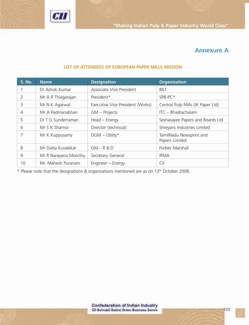
133
“Making Indian Pulp & Paper Industry World Class”
Annexure A
LIST OF ATTENDEES OF EUROPEAN PAPER MILLS MISSION
S. No. Name Designation Organization
1 Dr Ashok Kumar Associate Vice President BILT
2 Mr A R Thiagarajan President* SPB-PC*
3 Mr N K Agarwal Executive Vice President (Works) Central Pulp Mills (JK Paper Ltd)
4 Mr A Padmanabhan GM – Projects ITC – Bhadrachalam
5 Dr T G Sunderraman Head – Energy Seshasayee Papers and Boards Ltd
6 Mr S K Sharma Director (technical) Shreyans Industries Limited
7 Mr K Kuppusamy DGM – Utility* TamilNadu Newsprint andPapers Limited
8 Mr Datta Kuvalekar GM – R & D Forbes Marshall
9 Mr R Narayana Moorthy Secretary General IPMA
10 Mr. Mahesh Puranam Engineer – Energy CII
* Please note that the designations & organisations mentioned are as on 13th October 2008.

National & International Best Practices - Pulp & Paper Industry
134
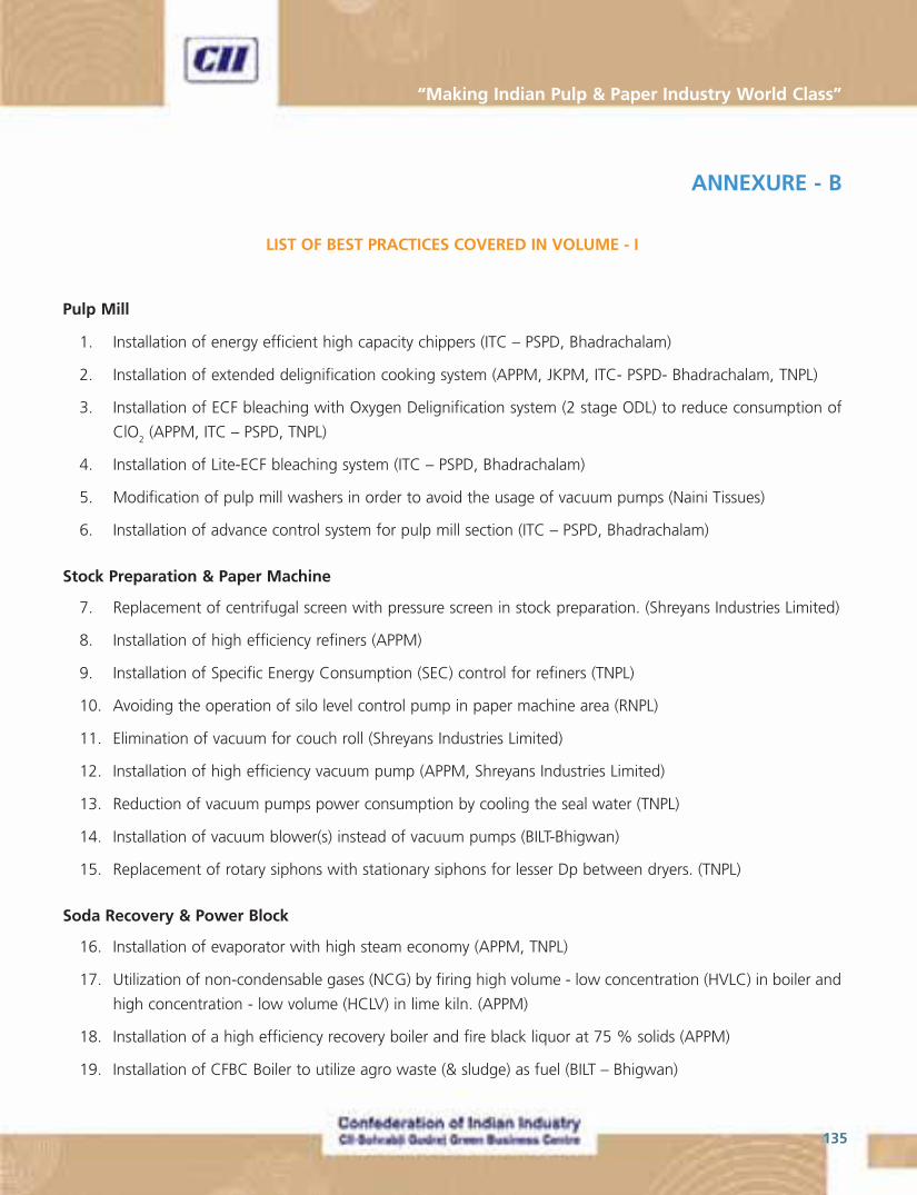
135
“Making Indian Pulp & Paper Industry World Class”
ANNEXURE - B
LIST OF BEST PRACTICES COVERED IN VOLUME - I
Pulp Mill
1. Installation of energy efficient high capacity chippers (ITC – PSPD, Bhadrachalam)
2. Installation of extended delignification cooking system (APPM, JKPM, ITC- PSPD- Bhadrachalam, TNPL)
3. Installation of ECF bleaching with Oxygen Delignification system (2 stage ODL) to reduce consumption of
ClO2 (APPM, ITC – PSPD, TNPL)
4. Installation of Lite-ECF bleaching system (ITC – PSPD, Bhadrachalam)
5. Modification of pulp mill washers in order to avoid the usage of vacuum pumps (Naini Tissues)
6. Installation of advance control system for pulp mill section (ITC – PSPD, Bhadrachalam)
Stock Preparation & Paper Machine
7. Replacement of centrifugal screen with pressure screen in stock preparation. (Shreyans Industries Limited)
8. Installation of high efficiency refiners (APPM)
9. Installation of Specific Energy Consumption (SEC) control for refiners (TNPL)
10. Avoiding the operation of silo level control pump in paper machine area (RNPL)
11. Elimination of vacuum for couch roll (Shreyans Industries Limited)
12. Installation of high efficiency vacuum pump (APPM, Shreyans Industries Limited)
13. Reduction of vacuum pumps power consumption by cooling the seal water (TNPL)
14. Installation of vacuum blower(s) instead of vacuum pumps (BILT-Bhigwan)
15. Replacement of rotary siphons with stationary siphons for lesser Dp between dryers. (TNPL)
Soda Recovery & Power Block
16. Installation of evaporator with high steam economy (APPM, TNPL)
17. Utilization of non-condensable gases (NCG) by firing high volume - low concentration (HVLC) in boiler and
high concentration - low volume (HCLV) in lime kiln. (APPM)
18. Installation of a high efficiency recovery boiler and fire black liquor at 75 % solids (APPM)
19. Installation of CFBC Boiler to utilize agro waste (& sludge) as fuel (BILT – Bhigwan)
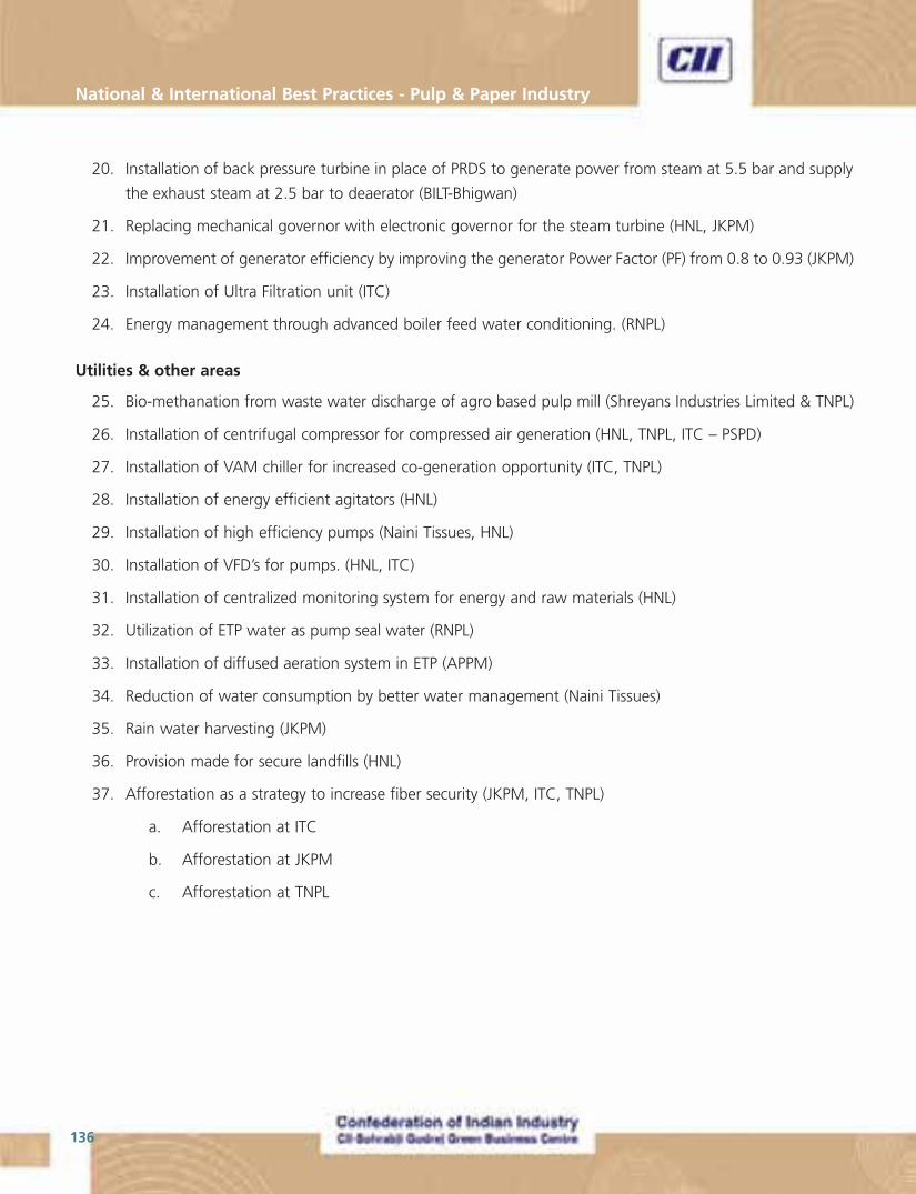
National & International Best Practices - Pulp & Paper Industry
136
20. Installation of back pressure turbine in place of PRDS to generate power from steam at 5.5 bar and supply
the exhaust steam at 2.5 bar to deaerator (BILT-Bhigwan)
21. Replacing mechanical governor with electronic governor for the steam turbine (HNL, JKPM)
22. Improvement of generator efficiency by improving the generator Power Factor (PF) from 0.8 to 0.93 (JKPM)
23. Installation of Ultra Filtration unit (ITC)
24. Energy management through advanced boiler feed water conditioning. (RNPL)
Utilities & other areas
25. Bio-methanation from waste water discharge of agro based pulp mill (Shreyans Industries Limited & TNPL)
26. Installation of centrifugal compressor for compressed air generation (HNL, TNPL, ITC – PSPD)
27. Installation of VAM chiller for increased co-generation opportunity (ITC, TNPL)
28. Installation of energy efficient agitators (HNL)
29. Installation of high efficiency pumps (Naini Tissues, HNL)
30. Installation of VFD’s for pumps. (HNL, ITC)
31. Installation of centralized monitoring system for energy and raw materials (HNL)
32. Utilization of ETP water as pump seal water (RNPL)
33. Installation of diffused aeration system in ETP (APPM)
34. Reduction of water consumption by better water management (Naini Tissues)
35. Rain water harvesting (JKPM)
36. Provision made for secure landfills (HNL)
37. Afforestation as a strategy to increase fiber security (JKPM, ITC, TNPL)
a. Afforestation at ITC
b. Afforestation at JKPM
c. Afforestation at TNPL

July 2009
“Make Indian Pulp & Paper Industry World Class”
Volume 2
National & International Pulp & Paper Industry
Best Practices Manual
About CII
About CII-Godrej GBC
About IPMA
The Confederation of Indian Industry (CII) works to create and sustain an environment conducive to the growth of industry in India, partnering industry and government alike through advisory and consultative processes.
CII is a non-government, not-for-profit, industry led and industry managed organisation, playing a proactive role in India's development process. Founded over 113 years ago, it is India's premier business association, with a direct membership of over 7500 organisations from the private as well as public sectors, including SMEs and MNCs, and an indirect membership of over 83,000 companies from around 380 national and regional sectoral associations.
CII catalyses change by working closely with government on policy issues, enhancing efficiency, competitiveness and expanding business opportunities for industry through a range of specialised services and global linkages. It also provides a platform for sectoral consensus building and networking. Major emphasis is laid on projecting a positive image of business, assisting industry to identify and execute corporate citizenship programmes. Partnerships with over 120 NGOs across the country carry forward our initiatives in integrated and inclusive development, which include health, education, livelihood, diversity management, skill development and water, to name a few.
Complementing this vision, CII's theme "India@75: The Emerging Agenda", reflects its aspirational role to facilitate the acceleration in India's transformation into an economically vital, technologically innovative, socially and ethically vibrant global leader by year 2022.
With 64 offices in India, 9 overseas in Australia, Austria, China, France, Germany, Japan, Singapore, UK, USA and institutional partnerships with 211 counterpart organisations in 87 countries, CII serves as a reference point for Indian industry and the international business community.
CII – Sohrabji Godrej Green Business Centre (CII – Godrej GBC), a division of Confederation of Indian Industry (CII) is India's premier developmental institution, offering advisory services to the industry on environmental aspects and works in the areas of Green Buildings, Energy Efficiency, Water Management, Renewable Energy, Green Business Incubation and Climate Change activities.
The Centre sensitises key stakeholders to embrace green practices and facilitates market transformation, paving way for India to become one of the global leaders in green businesses by 2015.
Indian Paper Manufacturers Association (IPMA) has emerged as a national level organisation and is an apex Association provides a broad based common platform to project Industry's view and to articulate its strategy to cater to the growing need and global vision of the Paper Industry. Large Paper Mills from private and public sector with a product mix of all varieties of Paper (Writing, Printing, Packaging, Speciality, Paper boards and Newsprint) located in all regions and using conventional fibre such as wood and bamboo and also unconventional raw materials like bagasse, recycled paper, etc. comprise the Membership of IPMA in a broad spectrum. The Association is registered with the Registrar of Societies, Government of NCT of Delhi.
IPMA strives to promote, protect and improve trade, commerce and Industry in general, with a focus on Industry connected with Paper in particular.
For more details, kindly contact
Survey No 64, Kothaguda Near HITEC City, Hyderabad - 500 084
Tel: +91 40 23112971-73 Fax: +91 40 23112837www.greenbusinesscentre.org