national radio astronomy observatory - 12 meter millimeter … · interoffice to: from: subject:...
TRANSCRIPT

Interoffice
To:
From:
Subject:
National Radio Astronomy Observatory Charlottesville, Virginia
May 26, 1981
Bill Horn
W - Y . Wong
12 METER MILLIMETER WAVE TELESCOPE
M E M O N o . g qA competing proposal for one 12-m reflector structure
Enclosed please find a proposal for the 12-m reflector design. I trust by the 29th of this month (last date for the concept design, see H. Hvatum’s memo no. 34), you will have all three proposals - Hor n’s, King’s and W o n g’s - in front of you to review. I hope you will exercise your most unbiased judgement and select a good one.

- 1 -
INTRODUCTION
To build a larger, deeper and better telescope without weight in
crease is a non-trivial engineering problem. Also, the 12-m replacement
must provide enough tie-down points to fit a given geometry of surface
panels. The structure itself must fit into the existing yoke. It should
be so designed that it can be taken apart into modules of manageable size
and weight for shipment, and can be assembled without the need for field
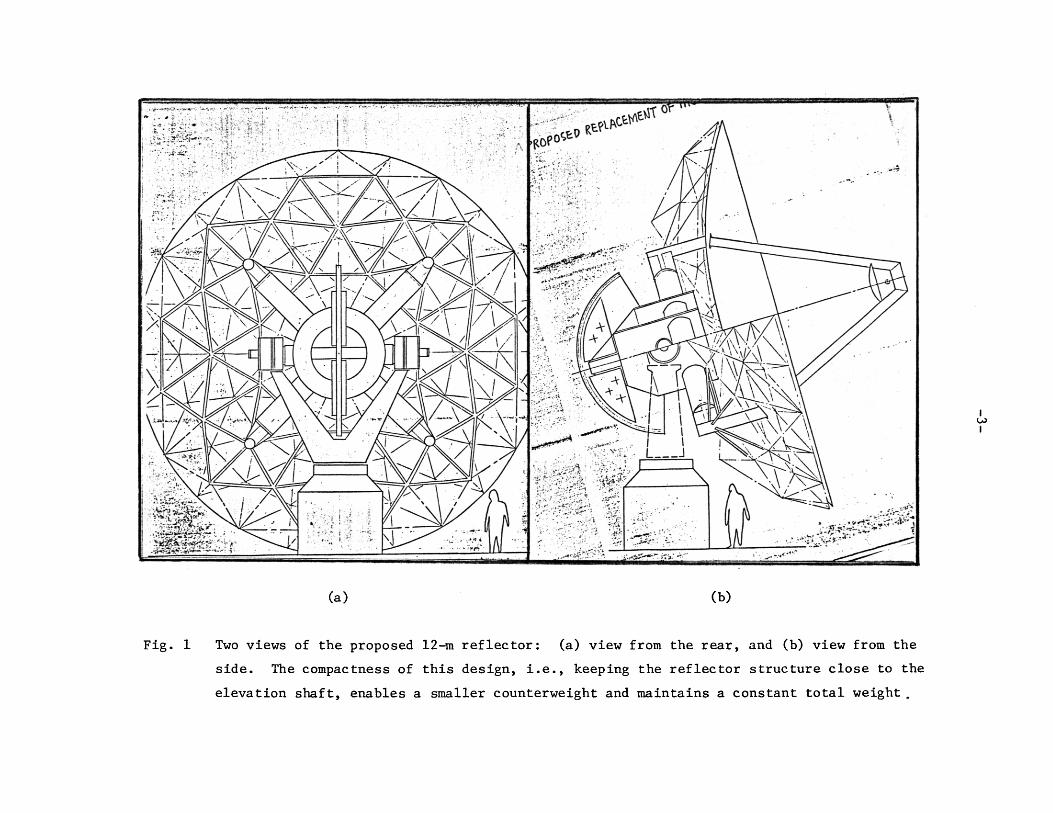
weldings. The proposed design, shown in Figures 1(a) and 1(b), fulfills
all these requirements.
This antenna design calls for the replacement of the entire existing
elevation structure. The removal of the existing structure entails the
loosening and disconnection of 20 bolts and one elevation bearing. The
installation of the new structure requires a reversal of the process.
This approach will shorten the telescope*s down time.
This design has a strong central hub, supporting the cross-beams and
the reflector on one end, the counterweight and the auxilliary elevation
wheel on the other. Four receiver mounting spaces are available on the
outside wall of the hub. The alignment of the receivers is 90° to the
telescope’s optical axis (J. Payne: 12-m memo 19, 4/16/81). This ex
terna lly-mounted concept provides a very direct reach to the receivers.
It is a departure from the conventional frontal vertex-mounted concept,
which requires a considerable amount of walking over the surface.
A rigid reference floor of 1.4 m in diameter behind the vertex is
available for the path length modulator mount during normal operation,
and for the measuring jig support during the measurement/setting period.
A circular track will also be available along the outer rim of the backup
structure for reference targets (J. Findlay: 12-m memo 36, 5/14/81).
- 2 -
As for telescope performance, it can be summarized as follows:
a) Gravity effects: la error from the backup structure alone is
estimated to be 0.025 mm rms, with a peak value of 0.031 mm.
b) Change of ambient temperature would cause the surface degradation
of 0.015 mm at the worst situation, around noon time when the rate is
estimated to be 5° C/hr., the la value is about 0.009 mm rms.
c) A temperature gradient across the telescope structure would
degrade the surface by the amount of 0.020 mm peak, 0.012 mm rms.
d) Thermal pointing caused by the reflector structure alone is
estimated to be 2.7 arc-sec peak, 1.6 arc-sec rms.
e) Estimated fundamental frequency of the structure is 11 Hz, and
the vibration mode is rocking about the elevation axis.
ILOI
(a) (b)
Fig. 1 Two views of the proposed 12-m reflector: (a) view from the rear, and (b) view from the
side. The compactness of this design, i.e., keeping the reflector structure close to the
elevation shaft, enables a smaller counterweight and maintains a constant total weight .
- 4 -
THE BASIC DESIGN CONCEPT
The problem facing this new 12-m design is clearly stated in the
previous section. The smaller f/D ratio produces a deeper structure,
causing a shift of the center of gravity further away from the elevation
axis (the shortening of the feed leg structure compensates some). Hence
the emphasis of the structural design is not on achieving a true homolo
gous solution, but on keeping the counter balance small.
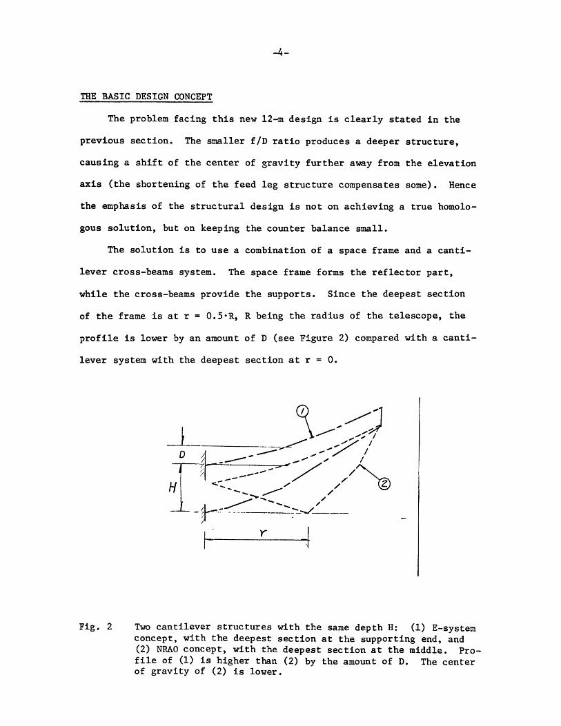
The solution is to use a combination of a space frame and a canti
lever cross-beams system. The space frame forms the reflector part,
while the cross-beams provide the supports. Since the deepest section
of the frame is at r = 0.5*R, R being the radius of the telescope, the
profile is lower by an amount of D (see Figure 2) compared with a canti
lever system with the deepest section at r = 0.
Fig. 2 Two cantilever structures with the same depth H: (1) E-system concept, with the deepest section at the supporting end, and (2) NRA.0 concept, with the deepest section at the middle. Profile of (1) is higher than (2) by the amount of D. The center of gravity of (2) is lower.

- 5 -
The space frame is a design (W. Wong: A 25-m Radio Telescope Design for
the VLB Array Project; 7/7/80) providing a large number of points on the
surface, and requires 4 supporting points on the back. It consists of a
relatively small number of members, with two different sizes.
The 4 cantilever cross-beams are 90° apart, clear entirely the
existing elevation bearings, motors and encoder packages on the top of
the yoke. This means one can locate the 4 beams as close as possible to
the elevation axis, limited only by the physical contact between the two
lower beams and the yoke arm as the telescope tilts to its lowest eleva
tion position. Due to the symmetry of the design, the stiffness of these
4 beams is equal.
This concept also provides an uncloistered space around the hub area,
rendering it possible to install receivers on the wall of the central hub.
SURFACE PANELS
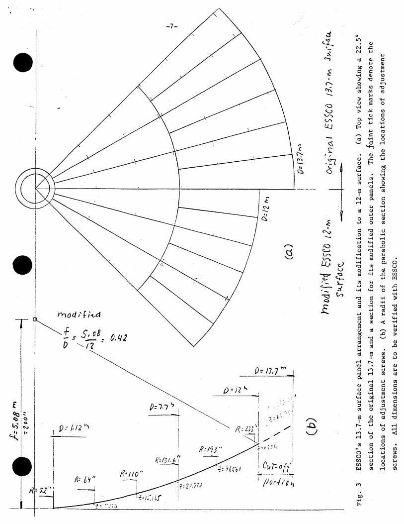
Figure 3 illustrates the surface panels used for the new reflector.
The geometry of the panels is based on the best information available,
but certainly will be subjected to some adjustment once the information
is verified with ESSCO. The thin tick marks in (a) denote the location
of the adjustment screws, with the corresponding radius in inches given
in (b). The cut-off surface forms a 12-m diameter reflector, and with
the original focal length of 5.08 m, the new surface has a f/D = 0.42.
There are 48 outer panels, and 24 inner panels. Each outer panel
has 6 adjustment screws, and each inner panel has 7 adjustment screws,
and a total of 456 screws.
The outer panel measures approximately 94 inches, with one end
measuring 31" wide and the other end 20” wide.
The inner panel measures approximately 134 inches, with one end
measuring 40" wide, and the other end 6" wide.
The total surface area is estimated to be 1,307.5 square feet. The
total weight is estimated to be 2,900 lbs.
/'
5,0
$
- z
oo"
o
• CUCMCM 4-1
4-1CO cu c
4-1 CU60 o 6C c 4-1•H cu CO
T 3 3O •r->£1 CO T 3co CO
}-ico I W
<u S O• H
> COa C
& • H OO 4-) • H
H 4-14-J CO
/ '- N c acd • H ov_> a r - \
CU• <ua) r C 4-1o HcO &0
M-l cVJ • ♦ H3 CO SCO r H O
<U .Ce C COi COCM a, ctH Ou • H
cO <u 4-14-1 O
O 3 cu4-J o CO
C oO a) • H•H • H r—14 J M-4 oco • H rQo T3 cO•H O U6 cO•H aT3 CO
O 4-1 cu6 • H rd4-1
CO U4-1 O 4-4•H 14-1 oT3 c • HC o • HCO •rH T3
4-J cO4 J O UC a)CU CO <ecu CO S-\60 &c T3 '_/Cfl CU cOU .cO n CO
i &t—i <ua) .C C O aco I—1 COCX
I—1 4-)cu cd Co e <ucd •rH 6IN bO 4-1
• H CO3 U PCO O '<—)e a) cOi X
4-1 4-4• oC O 14-1i—I o COc
CO c O— o •rHo • H 4-1CJ 4 J COCO O oCO cu Ow CO t—1co
60•HPn
All
dimensions
are
to
be
veri
fied
with
ESSCO.
- 8 -
THE CONSTRUCTION, ASSEMBLY AND DISASSEMBLY OF THE REFLECTOR
Considering that most of the construction will take place in Green
Bank, plus the subsequent test assembly, measurements, disassembly, and
shipment, the reflector should be built by modules. Figure 4 illustrates
the assembled end-product of the structure. And figures 5 and 6 depict
the bird's eye view of the modules laid out on the ground unassembled
(with some miscellaneous items not shown).
A list of the modules and their relevant information are given as
follows:
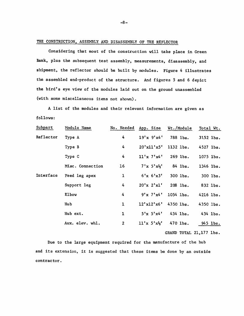
Subpart Module Name N o . Needed App. Size Wt./Module Total Wt.
Reflector Type A 4 19'x 9'x4' 788 lbs. 3152 lbs.
Type B 4 2 0 fx l l’x5* 1132 lbs. 4527 lbs.
Type C 4 11 *x 7*x4? 269 lbs. 1075 lbs.
Misc. Connection 16 7 ’x 5 fx V 84 lbs. 1346 lbs.
Interface Feed leg apex 1 6 ’x 6’x3' 300 lbs. 300 lbs.
Support leg 4 20'x 2 fxl* 208 lbs. 832 lbs.
Elbow 4 9'x 7’x4' 1054 lbs. 4216 lbs.
Hub 1 1 2 ,xl2lx6 * 4350 lbs. 4350 lbs.
Hub ext. 1 5'x 5 ,x 4 l 434 lbs. 434 lbs.
Aux. elev. whl. 2 11 *x 5 ' x V 470 lbs. 945 lbs.
GRAND TOTAL 21,177 lbs.
Due to the large equipment required for the manufacture of the hub
and its extension, it is suggested that these items be done by an outside
contractor.
- 9 -
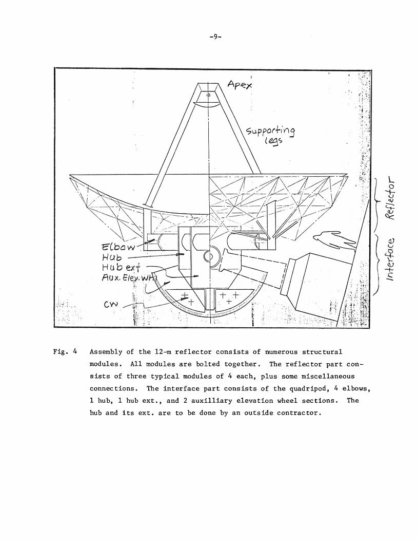
Fig. 4 Assembly of the 12-m reflector consists of numerous structural
modules. All modules are bolted together. The reflector part con
sists of three typical modules of 4 each, plus some miscellaneous
connections. The interface part consists of the quadripod, 4 elbows,
1 hub, 1 hub ext., and 2 auxilliary elevation wheel sections. The
hub and its ext. are to be done by an outside contractor.
/n-fe
r'-fa
ce
feflt
cfor
M c d a ie T y p e C r 4 -e a c h , u'xl'<4-'
- 1 0 -
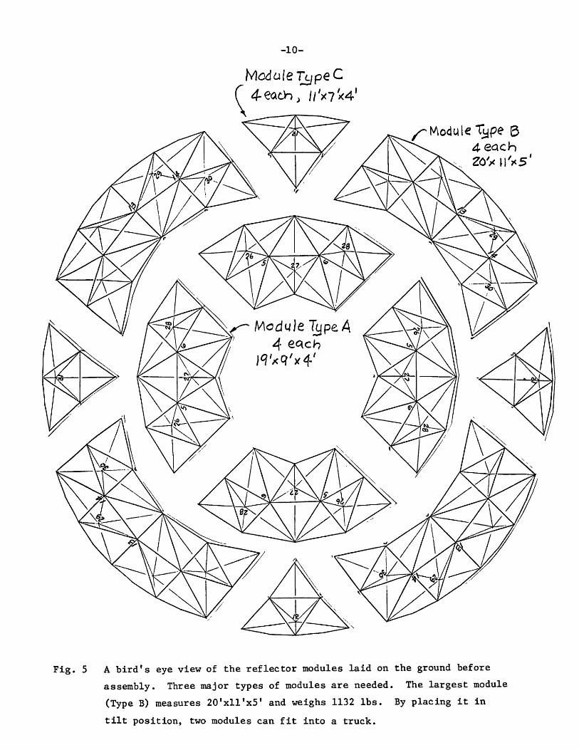
Fig. 5 A bird's eye view of the reflector modules laid on the ground before
assembly. Three major types of modules are needed. The largest module
(Type B) measures 20'xllfx 5 f and weighs 1132 lbs. By placing it in
tilt position, two modules can fit into a truck.
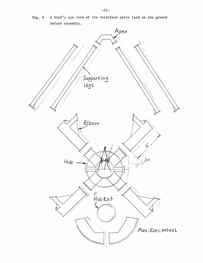
A bird's eye view of the interface parts laid on the ground
before assembly.

-1 2 -
WEIGHT AND INERTIA
The existing reflector, including all moving parts in elevation, has
the following data:
Structure wt. (incl. the surface, the back-up
structure and the feed supports) * 20,200 lbs.
Counter balance wt. = 23,720 lbs.
TOTAL = 43,920 lbs.
Moment of inertia about the elevation axis * 44,000 slug-ft. sq.
The new reflector has the following data:
Surface plates = 2,900 lbs.
Reflector & interface structure = 21,177 lbs.
Counter balance wt. = 20,000 lbs.
TOTAL = 44,077 lbs.
Estimated moment of inertia = 45,045 slug-ft. sq.
The new structure is overweight by < 1%, the moment of inertia is larger
by 2%.
-1 3 -
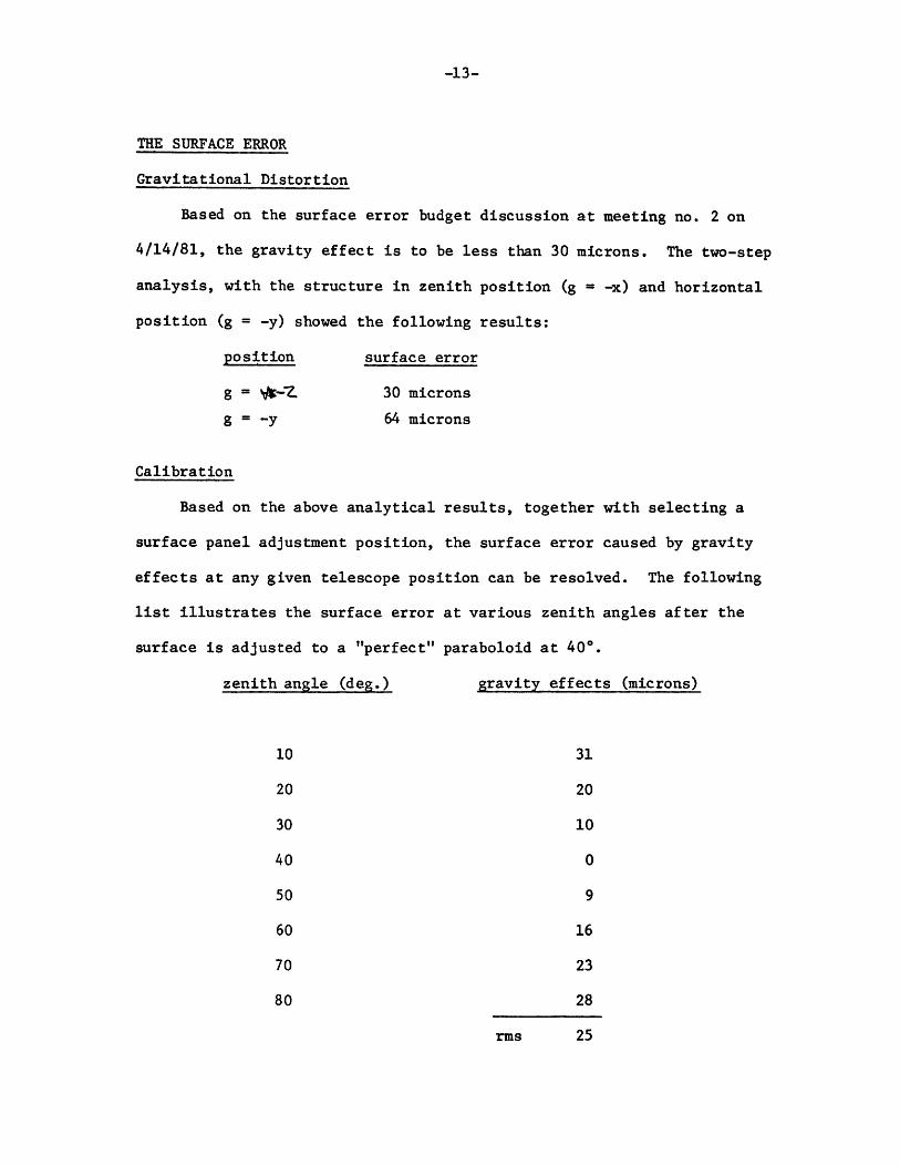
THE SURFACE ERROR
Gravitational Distortion
Based on the surface error budget discussion at meeting no. 2 on
4/14/81, the gravity effect is to be less than 30 microns. The two-step
analysis, with the structure in zenith position (g ■ -x) and horizontal
position (g = -y) showed the following results:
position surface error
g = 30 microns
g = -y 64 microns
Calibration
Based on the above analytical results, together with selecting a
surface panel adjustment position, the surface error caused by gravity
effects at any given telescope position can be resolved. The following
list illustrates the surface error at various zenith angles after the
surface is adjusted to a "perfect" paraboloid at 40°.
zenith angle (deg.) gravity effects (microns)
10 31
20 20
30 10
40 0
50 9
60 16
70 23
80 28
rms 25
-1 4 -
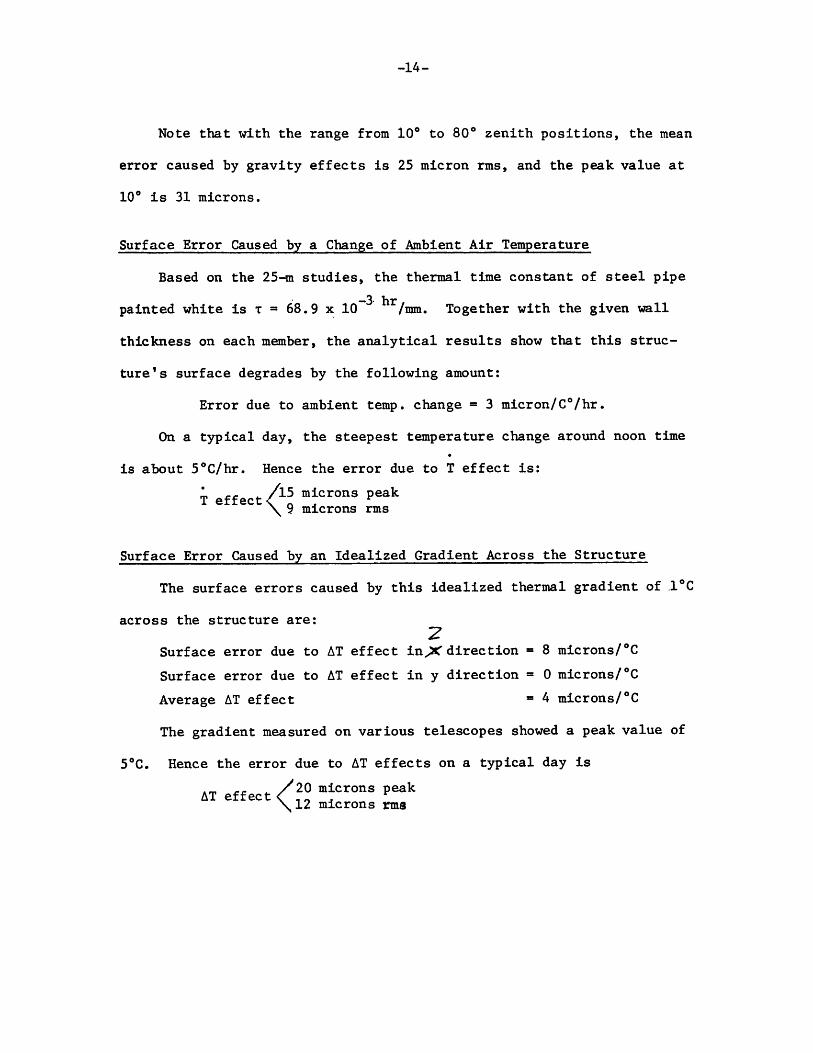
Note that with the range from 10° to 80° zenith positions, the mean
error caused by gravity effects is 25 micron rms, and the peak value at
10° is 31 microns.
Surface Error Caused by a Change of Ambient Air Temperature
Based on the 25-m studies, the thermal time constant of steel pipe
—3' hrpainted white is t = 68.9 x 10 /mm. Together with the given wall
thickness on each member, the analytical results show that this struc
t u r e d surface degrades by the following amount:
Error due to ambient temp, change = 3 micron/C°/hr.
On a typical day, the steepest temperature change around noon time
is about 5°C/hr. Hence the error due to T effect is:
’ /15 microns peakT effects . . r
\ 9 microns rms
Surface Error Caused by an Idealized Gradient Across the Structure
The surface errors caused by this idealized thermal gradient of 1°C
across the structure are: zSurface error due to AT effect i n ^ X direction = 8 microns/°C
Surface error due to AT effect in y direction = 0 microns/°C
Average AT effect = 4 microns/°C
The gradient measured on various telescopes showed a peak value of
5°C. Hence the error due to AT effects on a typical day is
AT effect / ? ? m *Crons peak \ 1 2 microns rms

- 1 5 -
THERMAL POINTING
A temperature difference across the telescope structure also causes
a slight rotation of the best fit paraboloid. This rotation is a com
bination of various mechanical deflections, together with the optical
characteristics of the telescope. From the analyses, the beam tilt due
to 1°C across the structure is computed and described as follows:
0 (Am) = Beam tilt due to the lateral motion of the main reflector —6
“ +2.8 x 10 rad
0 (otm) = Beam tilt due to the rotation of the main reflector
= -1.0 x 10 ^ rad
0 (As) = Beam tilt due to the lateral motion of the subreflector
= -4.0 x 10 ^ rad
0 (as) = Beam tilt due to the rotation of the subreflector
= -0.4 x 10 6 rad
0 (AP) = Beam tilt due to the lateral motion of the phase center
= 0
The combined beam tilt due to 1°C temperature difference is the sum
of these contributions, or:
0 = -2.6 x 10"6 rad/C° = -0.54 sec/C°
The mean temperature difference on a typical day is 2.9° C, and the
peak value is 5.0° C. The corresponding thermal pointing is estimated
to be:
Thermal pointing S6C )̂ea^r ° \ 1 . 6 sec avg.