national radio astronomy observatory … · national radio astronomy observatory green bank, west...
TRANSCRIPT
NATIONAL RADIO ASTRONOMY OBSERVATORYGreen Bank, West Virginia
Electronics Division Internal Report No. 49
POSITION READOUT SYSTEMSFOR 85-1, 85-2, AND NIKE MOUNT
Claude C. Bare
SEPTEMBER 1965
NUMBER OF COPIES: 75
40 . es.
POSITION READOUT SYSTEMS FOR 85-1 85-2 AND NIKE MOUNT
Claude C. Bare
The readout receives data from two 17-bit binary encoders and from the
sidereal clock. Electrical binary coded decimal and nixie outputs are provided for
Declination, Hour Angle and Right Ascension. One encoder bit equals approximately
9. 89- seconds of arc and 0. 66 seconds of time angle. Since these numbers are not
integers, the output resolution must be greater than the encoder resolution. The error
on Hour Angle and Right Ascension due to conversion does not exceed 0.05 seconds of
time angle.
The maximum =certainty of Declination is estimated to be ± 8.4 seconds of
arc (0. 5 conversion, 4.9 encoder resolution, and 3iencoder error). The maximum
uncertainty of Hour Angle and Right Ascension is estimated at . 58 seconds of time
angle (.05 conversion, .33 encoder resolution, and . 2 encoder error). Mechanical
errors occurring before the encoder are not included.
The encoders are Baldwin 17-bit binary encoders, model 1011, with negative
output niodules. The logic is performed with commercial logic cards by Computer
Control Corporation. The 200 kc S-pac series of cards are used.
A position transmitter and position receiver will be constructed to provide a
- readout of the position of the remote telescope in the main telescope control room.
Only the 85-2 readout has output connectors to drive the position transmitter.
IL Controls
The power switch on the right side of the panel controls all the logic volt
The 200 volt power for the nixie readouts does not pass through the logic system.
A similar group of controls for both the encoders are provided. The "strobe
test" banana jack indicates the lamp is flashing in the encoder. An amplitude "adjust"
pot and a "test" jack are provided for the "Interrogation Pulse". The Interrogation
Pulse should be adjusted to the minimum signal that gives consistent triggering of
the strobe lamp. In the "amp test" position the Interrogation Pulse generator is
switched from the Interrogation Pulse coax to the amplifier test encoder coax. The
amplifier test signals cause all the output amplifiers in the encoder to give an output.
These encoder outputs are available on a terminal strip behind the front panel. The1
clock slave supplies the pulse that starts the readout process every 10
second.
IlL Block Di ram
The data is received from the 17-bit Baldwin encoder in gray code. The data
is converted to non-cyclic binary code in a modified shift register. This is accomplished
by shifting the data 16 times (places) around the 17-bit register. Refer to figure 1.
Each binary bit in the register now represents a specific number of hours or
degrees, minutes, seconds, and tenths of seconds. Refer to table 1 for degrees and to
table 2 for hours. The most significant digit represents half of a rotation of the encoder
(180 degrees or 12 hours). The second digit represent 1/4 of a revolution, the third
1/8 revolution, etc. The last digit (the seventeenth) represents approximately 9. 89
seconds of arc or approximately 0. 66 seconds of time angle.
The three output registers are designated Declination Counter, Hour Angle
Counter, and Right Ascension Counter. A counter is set to zero and then caused to
count the proper number of pulses to reach the correct output. The three registers are
slightly different in actual operation. The most complicated one (Right Ascensipn
Counter) will be discussed first.
The Right Ascension Counter is first reset, then loaded with sidereatime ,), an
then counted up by amount measured by the polar encoder. The R. A. Counter is
divided up by decimal digits into grout,. ......s" . See table 2. The "columns"
are further divided into four "rows".
At the beginning of each new "column" the sidereal time is loaded into that
decimal digit (or digits) represented by the new "cOlumn" •• For each "row" one and
only one of each "weight one", "weight two", "weight four", and "weight eight" are
loaded into the "Scaler Down Counter" by the "Scaler Gates". The binary weights
loaded follow the rules shown in table 2. The "Down Counter" now holds a number
3
from 0 to 15, depending upon the bits loaded. At the same time that the "Down
Counter" is counted down to zero the same pulses are fed to the decimal digit selected
by the column number. After this operation is repeated for each "row" , this decimal
digit will be counted up by the required amount.
The Hour Angle Counter is loaded similarly to the Right Ascension Counter.
Two major differences exist. Time is not loaded into the register. The most signifi-
cant encoder digit represents East or West instead of 12 hours. The Gray to Binary
Converter is not loaded with the most significant digit. The binary code then becomes
a mirror code with two zero' s and increasing in number (count) in both directions from
zero. The West zero is eliminated by adding O. 7 seconds of time to the Hour Angle
Register if the angle is West.
The Declination Counter also uses the most significant encoder bit as a sign
bit. The Declination Scaler Gates are used for this register. These gates follow the
rules in table 1. This is the only output that is displayed in degrees, minutes, and
seconds. Some of the numbers from table 1 are placed into the Declination Counter
without using the Declination Scaler Gates and the Scaler Down Counter. The directly
loaded numbers are indicated by a "D" in table 1. A decimal digit may be loaded with
a "two", and a ftfo----tta "one" , Ur without error. A senary digit may be loaded with a
"one" and a "two".
IV. Logic Sequence of Operations
This section is written with the service of the equipment in mind. It is not
recommended reading for the general knowledge of the system. Refer to logic drawings
DL 1350, DL 1351, and DL 1352 for the readout system at the 85-2. The drawings for
the 85-1 are DL 1250, DL 1251, and DL 1252. The system at the 85-1 has the added
feature of sampled encoder lines. The readout system for the 12-foot (nike mount)
telescope (drawings DL 850, DL 851, and DL 852) is somewhat similar to the 85-foot
systems. The standard 3C logic symbols are used for the logic drawing. Literature
describing 3C logic is recommended reading. In order to guide someone through the
logic drawings, the following sequence of operations is provi ded:
1End of "0. 1 AT" (starts operation each io second).
20 p,sec pulse on T8 Block 2, set "F21"; reset "F22".
P20 p,sec pulse at
"SEB" and
"SEA?! interrogate polar en-
coder, "RDRR " (reset Right Ascension Decimal
Register); reset Shift Register.
Encoder data loaded into shift register (under control of
encoder at 85-2; under control of "SEC at 85-1.
Set "F204".
Shift the Gray to Binary Shift Register 16 times.
Reset "F204".
Pulse on TP2 block 2; reset Column Counter, "C2" state.
Set "F205"; start Row Counter, "RI" state (F206 is in
reset state); load Scaler with "Ps" pulse (F21 selects
H. A. and R. A. Scaler Gates). Note that table 2
specified that nothing will be loaded into the scaler
during C2 R1; "Pz" causes sidereal time hour to be
loaded into the Right Ascension Counter.
F206 is not set since the Scaler is already on "zero"
F205 reset.
Set F205; step Row Counter to state R2; nothing is loaded
into the scaler on C2 R2; reset P205.
Set F205 row counter to state R3; under control of "Ps"
load a "4" and an "8" into scaler if "Fl" is true;
load a "1" and a "2" if "F2" is true.
Assuming Scaler is loaded with something, Set F206; reset
F205; begin counting down Scaler and counting up unit
hours of the Right Ascension Counter; "PCR" controls
the counting up of the R. A. Counter.
Scaler reaches count "one" ; reset F206.

Set F205; advance "Row Counter" to "111"; advance "Column
Counter" to "C3" . Load tens of minutes of sidereal
time into the Right Ascension Counter; load the Scaler
with a "one" and a "two" if F4 is true and with a "four"
if F5 is true.
Repeat above operations until end of 08 R4 advances Column
Counter to "C9"; the Row Counter goes to a "no action"
state; pulse on TP9 block 2.
Pulse TP10 block 2, toggle F21 to pulse state; set F22.
Pulse on SEA
and SEB interrogate Declination Encoder; reset'
Declination Counter; reset Shift Register.
The most significant encoder bit is loaded into the North-South
flip-flop (Fs). The remaining encoder bits are loaded
into the Shift Register and are converted to binary code
from gray code.
F204 reset (starts) Column Counter.
C2 R2 produces P •PD' loads data into Declination Counter with-
out using the Scaler Gate and the Scaler.
C2 R4 is the time the Scaler is first used. The counting-up
process of the Declination Counter proceeds like the
Right Ascension Counter except the Declination Scaler
Gates are used.
End of C8 R4; step to C9 and to a "no action" state of the
Row Counter; pulse TP9 block 2.
Pulse on TP10 block 2; toggle F21 (F21, F22 now selects
Hour Angle measurement).S
EA' SEB'
reset Hour Angle Counter; reset shift register;
interrogate Polar Encoder. (The readout system'is
slowed down to allow the Polar Encoder time to re-
cover from the previous readout.)
Encoder data is loaded into the Shift Register. The most
significant encoder digit is loaded into E." instead
of the shift register.
At the completion of R4 C8 the system is inhibited
from restarting by F22. The system is now waiting1for the next 0. 1 AT at the next second.
10
V. Spçi eCaal
One special purpose card is required in the Position Readout System. The
card contains two Interrogation Driver Circuits. Refer to Digital Drawing DS 875.
Each circuit consists of a two input "and" gate, and emitter follower, and. an inverting
output amplifier. This amplifier is AC coupled to the encoder cable. The "--12 volts
to gnd" pulse at the output of the transistor produces a "gnd to +12 volt" pulse on the
encoder cable.
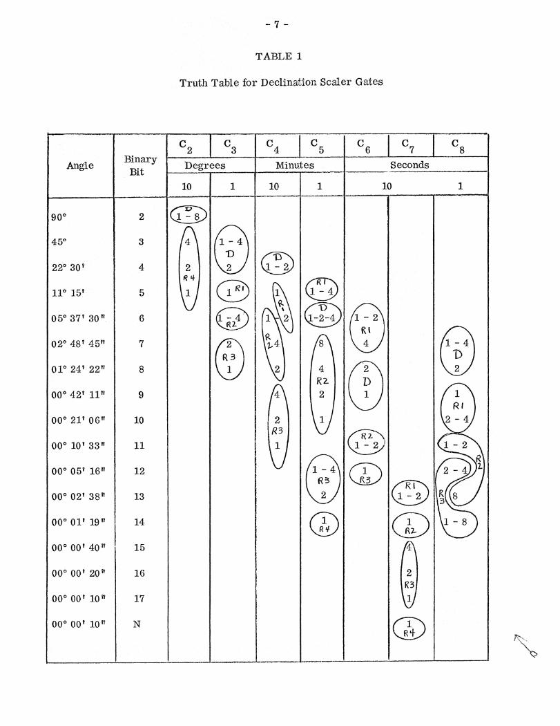
TABLE 1
Truth Table for Declination Sc er Gates
Angle Binary4
C5
C7
C
Bit ,.......,..............Minutes Seconds
.........„,......10 1 10 1
Icy90° 2 1 - 8
45° 3 4 1 - 41) 1)
220 301 4 2 1 - 2R I
11°15' 5 1Ri 1 - 4
D05° 37' 30" 6 1 - 4
R2.,
•
1-2-4 _
R I02° 48' 45" 1 - 4
R 3 D
01° 24' 22 n 8 2R 2-
00 0 42? 11" 9 4 2 1 1RI
000 21' 06" 10 1
ii2-
2 - 4
000 10' 33" 11 .... 1 - 2
R00
0 05' 16 n 12 i
1 - 4 i 2 - 4 i
000 02 1 38" 13
, R32
1 3Ri
1 - 2
000 01' 19" 14 1 1 - 8
R it
000 00' 40" 15
000 00' 20" 16
R300
0 00' 10 n 17 1
000 00' 10 n N 1
Ri
_
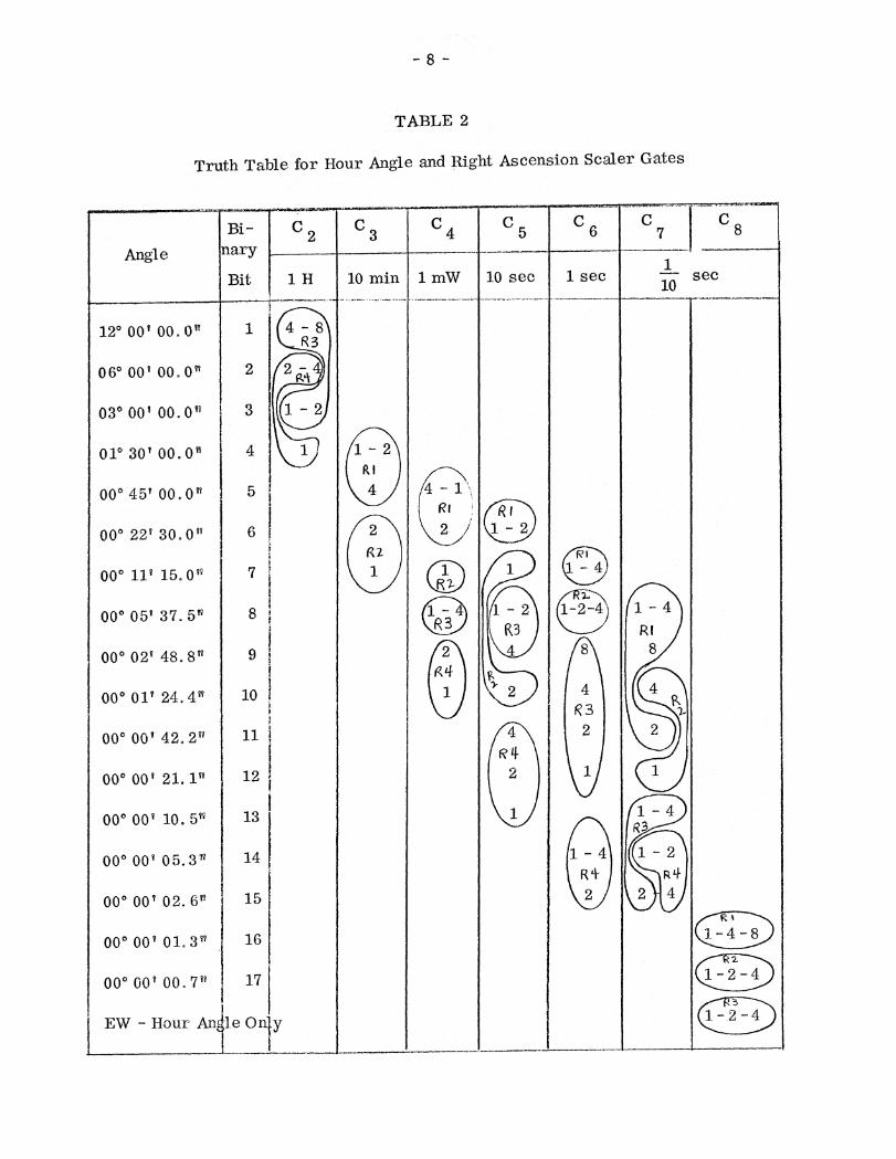
12° 00' 00.0"
06° 00' 00.0"
03° 00 1 00.0"
010 30' 00.0"
000 45 00.0"
00 0 22' 30.0"
00 0 11' 15.0"
00 0 05' 37.5"
00 0 02' 48.8"
00* 01' 24.4"
000 00' 42.2"
000 00' 21.1"
000 00' 10.5"
00 0 00' 05.3"
000 00' 02.6"
000 00' 01.3"
000 00' 00.7"
EW - Hour An
5
6
7
8
9
10
11
12
13
14
15
16
17
10 min
le Only
TABLE 2
Truth Table for Hour Angle and Right Ascension Sealer Gates
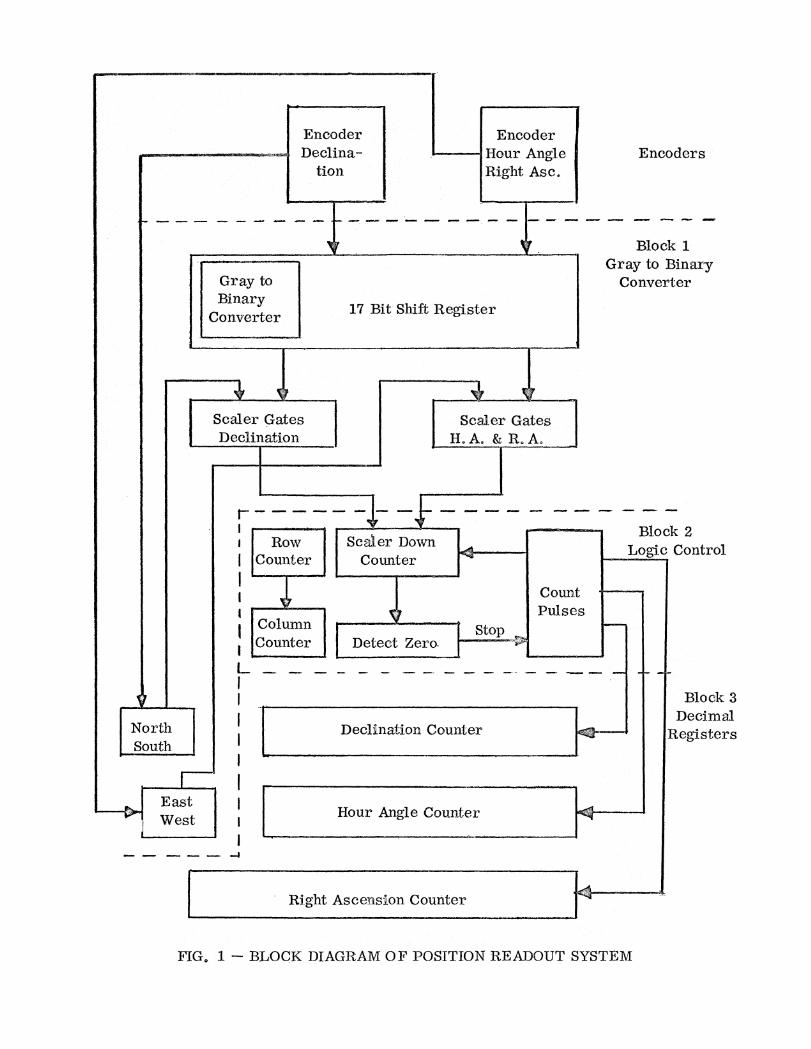
FIG. 1 — BLOCK DIAGRAM OF POSITION READOUT SYSTEM
17 Bit Shift Register
Block 1Gray to Binary
Converter
Scaler GatesDeclination
NorthSouth
EastWest
Gray toBinary
Converter
EncoderDeclina-
tionEncoders
r_. •■■••10.
Block 2Logic Control
Block 3Decimal.
Registers
Hour Angle Counter
Right Ascension Counter
CountPulses
ColumnCounter Detect Zero.
Stop
Scaler DownCounter
••■•■•■••• •••••■■■■■ •••■•..
Declination Counter
EncoderHour AngieRight Asc.