national renewable energy laboratory (nrel) topic 2 … · · 2018-02-22national renewable energy...
TRANSCRIPT

National Renewable Energy Laboratory (NREL) Topic 2 Final Report End-to-End Communication and Control System to Support Clean Energy Technologies
2017 TECHNICAL REPORT

National Renewable Energy Laboratory (NREL) Topic 2
Final Report
End-to-End Communication and Control System to Support Clean Energy Technologies
EPRI Project Manager J. Simmins
3420 Hillview Avenue Palo Alto, CA 94304-1338
USA
PO Box 10412 Palo Alto, CA 94303-0813
USA
800.313.3774 650.855.2121
[email protected] 3002011500 www.epri.com Final Report, August 2017

DISCLAIMER OF WARRANTIES AND LIMITATION OF LIABILITIES
THIS DOCUMENT WAS PREPARED BY THE ORGANIZATION(S) NAMED BELOW AS AN ACCOUNT OF WORK SPONSORED OR COSPONSORED BY THE ELECTRIC POWER RESEARCH INSTITUTE, INC. (EPRI). NEITHER EPRI, ANY MEMBER OF EPRI, ANY COSPONSOR, THE ORGANIZATION(S) BELOW, NOR ANY PERSON ACTING ON BEHALF OF ANY OF THEM:
(A) MAKES ANY WARRANTY OR REPRESENTATION WHATSOEVER, EXPRESS OR IMPLIED, (I) WITH RESPECT TO THE USE OF ANY INFORMATION, APPARATUS, METHOD, PROCESS, OR SIMILAR ITEM DISCLOSED IN THIS DOCUMENT, INCLUDING MERCHANTABILITY AND FITNESS FOR A PARTICULAR PURPOSE, OR (II) THAT SUCH USE DOES NOT INFRINGE ON OR INTERFERE WITH PRIVATELY OWNED RIGHTS, INCLUDING ANY PARTY'S INTELLECTUAL PROPERTY, OR (III) THAT THIS DOCUMENT IS SUITABLE TO ANY PARTICULAR USER'S CIRCUMSTANCE; OR
(B) ASSUMES RESPONSIBILITY FOR ANY DAMAGES OR OTHER LIABILITY WHATSOEVER (INCLUDING ANY CONSEQUENTIAL DAMAGES, EVEN IF EPRI OR ANY EPRI REPRESENTATIVE HAS BEEN ADVISED OF THE POSSIBILITY OF SUCH DAMAGES) RESULTING FROM YOUR SELECTION OR USE OF THIS DOCUMENT OR ANY INFORMATION, APPARATUS, METHOD, PROCESS, OR SIMILAR ITEM DISCLOSED IN THIS DOCUMENT.
REFERENCE HEREIN TO ANY SPECIFIC COMMERCIAL PRODUCT, PROCESS, OR SERVICE BY ITS TRADE NAME, TRADEMARK, MANUFACTURER, OR OTHERWISE, DOES NOT NECESSARILY CONSTITUTE OR IMPLY ITS ENDORSEMENT, RECOMMENDATION, OR FAVORING BY EPRI.
THE ELECTRIC POWER RESEARCH INSTITUTE (EPRI) PREPARED THIS REPORT.
ACKNOWLEDGEMENTS IN SUBCONTRACTOR PUBLICATIONS
IN ANY SCIENTIFIC OR TECHNICAL REPORT OR ARTICLE, CONFERENCE PAPER, JOURNAL ARTICLE, ETC. BASED ON OR CONTAINING DATA FIRST PRODUCED IN THE PERFORMANCE OF THIS SUBCONTRACT AND PUBLISHED IN ACADEMIC, TECHNICAL OR PROFESSIONAL JOURNALS, SYMPOSIA PROCEEDINGS OR SIMILAR WORKS, THE SUBCONTRACTOR SHALL USE THIS ACKNOWLEDGEMENT STATING, “THIS [ARTICLE, CONFERENCE PAPER, JOURNAL ARTICLE, ETC.] WAS DEVELOPED BASED UPON FUNDING FROM THE ALLIANCE FOR SUSTAINABLE ENERGY, LLC, MANAGING AND OPERATING CONTRACTOR FOR THE NATIONAL RENEWABLE ENERGY LABORATORY FOR THE U.S. DEPARTMENT OF ENERGY.”
NOTE
For further information about EPRI, call the EPRI Customer Assistance Center at 800.313.3774 or e-mail [email protected].
Electric Power Research Institute, EPRI, and TOGETHER…SHAPING THE FUTURE OF ELECTRICITY are registered service marks of the Electric Power Research Institute, Inc.
Copyright © 2017 Electric Power Research Institute, Inc. All rights reserved.

Acknowledgments The Electric Power Research Institute (EPRI) prepared this report.
Principal Investigator J. Simmins
This report describes research sponsored by EPRI and the National Renewable Energy Laboratory as part of the Integrated Network Testbed for Energy Grid Research and Technology Experiment (INTEGRATE).
This publication is a corporate document that should be cited in the
literature in the following manner:
National Renewable Energy Laboratory (NREL) Topic 2 Final
Report: End-to-End Communication and Control System to Support
Clean Energy Technologies. EPRI, Palo Alto, CA: 2017.
3002011500.
iii

Abstract
This document is the final report of a two-year development, test, and demonstration project, “Cohesive Application of Standards- Based Connected Devices to Enable Clean Energy Technologies.” The project was part of the National Renewable Energy Laboratory’s (NREL’s) Integrated Network Testbed for Energy Grid Research and Technology (INTEGRATE) initiative hosted at Energy Systems Integration Facility (ESIF). Specifically, this project is a component of RFP Number RCS-4-42326, Topic 2, “End-to-End Communication and Control System to Support Clean Energy Technologies.”
This project demonstrated techniques to control distribution grid events using the coordination of traditional distribution grid devices and high-penetration renewable resources and demand response. Using standard communication protocols and semantic standards, the project examined the use cases of high/low distribution voltage, requests for volt-ampere-reactive (VAR) power support, and transactive energy strategies using Volttron. Open source software, written by EPRI to control distributed energy resources (DER) and demand response (DR), was used by an advanced distribution management system (ADMS) to abstract the resources reporting to a collection of capabilities rather than needing to know specific resource types. This architecture allows for scaling both horizontally and vertically.
Several new technologies were developed and tested. Messages from the ADMS based on the common information model (CIM) were developed to control the DER and DR management systems. The OpenADR standard was used to help manage grid events by turning loads off and on. Volttron technology was used to simulate a homeowner choosing the price at which to enter the demand response market. Finally, the ADMS used newly developed algorithms to coordinate these resources with a capacitor bank and voltage regulator to respond to grid events.
Keywords Demand response Distributed energy resources Distribution feeder Integration
v

EXECUTIVE SUMMARY
Deliverable Number: 3002011500 Product Type: Technical Report
Product Title: National Renewable Energy Laboratory (NREL) Topic 2 Final Report: End-to-End Communication and Control System to Support Clean Energy Technologies
PRIMARY AUDIENCE: This research would be used by engineers and engineering managers engaged in planning for high levels of DER.
SECONDARY AUDIENCE: Individuals interested in advanced DMS or DER/DR control.
KEY RESEARCH QUESTION
With higher penetration levels of distributed energy resources (typically photovoltaic, small wind, storage, and so on) on distribution feeders, can these assets be coordinated with demand response to augment or replace standard methods of distribution feeder control? Several typical distribution scenarios are tested to determine the viability of using distribution energy resources and demand response to support an overvoltage situation, an undervoltage situation, and transmission VAR support. Also tested were IEC 61968 messages and OpenADR messages that were developed to support distribution management system control using these resources.
RESEARCH OVERVIEW
EPRI built a feeder simulator that consisted of 10 simulated miles of feeder with the ability to connect any kind of device or circuit at each node. These nodes were installed in two electronics racks. Typical SCADA (supervisory control and data acquisition) -controlled devices (a voltage regulator and a capacitor) were located at the middle of the simulated feeder. These devices are used to raise the voltage along a feeder to mitigate voltage drop. In addition to the SCADA-controlled devices, groups (described below) of distributed energy resources (DER) and demand response (DR) resources were installed at various nodes above and below the SCADA-controlled devices. These groups were controlled by two open source software packages developed by EPRI. Requests from an advanced distribution management system (ADMS) were sent to these software packages via the enterprise service bus (ESB). Each of these software packages then decided how best to fulfill the request.
KEY FINDINGS Ô Open standards are sufficient to enable groups of connected devices to be monitored and managed
effectively. Ô A recursive architecture is one way to create a flexible solution to manage and dispatch DER and DR
resources. Ô Aggregating software packages such as OpenDERMS and OpenDRAS can be used by an ADMS to
control groups of resources without any knowledge of the resources they represent. Ô DER and DR can be coordinated using a commercial ADMS package through the use of resource
groups.
vii

EXECUTIVE SUMMARY
WHY THIS MATTERS
Normally, high penetrations of DER are something of a liability for the distribution utility operations group. The results of this research show that DER can be an asset to operations by providing additional options for distribution grid voltage control and transmission support. This research demonstrates that DER and DR can be dispatched for a variety of reasons by advanced distribution management systems in groups as if the group consisted of one resource.
HOW TO APPLY RESULTS
This project proves the concept of grouping individual resources as a single, abstract entity for dispatch purposes. In addition, this project proves that this abstracted resource can be dispatched for a variety of responses in support of distribution grid operations. The results of this research could be applied to a project of similar complexity on an actual medium-voltage distribution circuit. A more complicated experiment on the same feeder simulator could be attempted to explore greater applicability of the concepts. Finally, these results could be applied to a project on Blockchain and smart contracts.
LEARNING AND ENGAGEMENT OPPORTUNITIES
Ô EPRI has conducted numerous studies on both the architecture and the individual standards applied in this study:
o 3002009854, Summary of Interoperability and Functionality Testing of SunSpec Inverters o 3002009462, Results from Inverter Interoperability Assessment Using the SunSpec
Specification: Summary of EPRI’s Testing of Communications in Residential Solar
o 3002003035, DER Enterprise Integration: Interoperability Workshop Results o 3002003451, Automated Demand Response and Ancillary Services Demonstration Project
Newsletter
o 3002002709, CEA-2045 Laboratory Device Testing: Duke Energy, EnergyWise Lab o 1026542, Modular Communication Interface Interoperability Workshops: Laboratory
Evaluation of the CEA-2045 Demand Response Interface
Ô This deliverable applies to any utility interested in integrating smart distribution assets, smart solar, and smart loads on its distribution system. The project looks at topics that span the Information and Communication Technology Program but also applies to programs researching the end devices (distribution system equipment, solar, and demand response).
EPRI CONTACTS: John J. Simmins, Technical Executive, [email protected]
PROGRAM: Information and Communication Technology (P161C) Together...Shaping the Future of Electricity®
Electric Power Research Institute 3420 Hillview Avenue, Palo Alto, California 94304-1338 • PO Box 10412, Palo Alto, California 94303-0813 USA
800.313.3774 • 650.855.2121 • [email protected] • www.epri.com © 2017 Electric Power Research Institute (EPRI), Inc. All rights reserved. Electric Power Research Institute, EPRI, and
TOGETHER...SHAPING THE FUTURE OF ELECTRICITY are registered service marks of the Electric Power Research Institute, Inc.

Table of Contents Abstract ......................................................................... V
Executive Summary .................................................... VII
Section 1: Project Overview .................................... 1-1 1.1 Project Accomplishments ......................................... 1-3 1.2 Project Team ............................................................ 1-3 1.3 Key Concepts Developed in the INTEGRATE Task 2 Project ............................................................................. 1-4
1.3.1 Recursive Architecture .................................... 1-4 1.3.2 Use of Open Standards ................................... 1-5 1.3.3 Resource Groups ............................................ 1-5 1.3.4 Enterprise Service Bus .................................... 1-6 1.3.5 Open Applications ...........................................1-6 1.3.6 Open Semantic Standard Test Harness (OpenSSTH) ..............................................................1-6
Section 2: Laboratory Testing and Result Highlights ................................................. 2-1
2.1 Feeder-Level Voltage Management .........................2-2 2.2 Protecting and Optimizing the Use of Grid Assets ....2-3
2.2.1 Goal .................................................................2-3 2.2.2 Results .............................................................2-3
2.3 Transactive Energy ...................................................2-4 2.3.1 Goal .................................................................2-4 2.3.2 Results .............................................................2-4
2.4 VAR Support for Transmission ................................ 2-4 2.4.1 Goal ................................................................ 2-4 2.4.2 Results ............................................................ 2-4
Section 3: Conclusion and Analysis ....................... 3-1 3.1 Value of ESIF ........................................................... 3-1 3.2 Impact on Stakeholders ........................................... 3-1 3.3 Standards Assessment ............................................ 3-1
3.3.1 OpenADR 2.0b ............................................... 3-1 3.3.2 CTA-2045 ........................................................ 3-2 3.3.3 IEC 61850-90-7 and IEC 61850-7-420 ........... 3-2
ix

3.3.4 Distributed Network Protocol: DNP3 ............... 3-2 3.3.5 Volttron ............................................................ 3-2 3.3.6 Common Information Model – IEC 61968 ....... 3-3
3.4 Key Take-aways ....................................................... 3-3
Section 4: Future Research ..................................... 4-1
x

List of Figures
Figure 1-1 One-line schematic of the simulated feeder and group configuration used in this project .......................... 1-1
Figure 1-2 Electronics rack with seven lumped impedance nodes, cooling and control equipment. Two of these racks were used in the INTEGRATE Task 2 project. ........ 1-2
Figure 1-3 Project Team ....................................................... 1-4
Figure 1-4 Recursive architecture consisting of abstract virtual top nodes (VTNs) and virtual end nodes (VENs). .. 1-5
Figure 2-1 ADMS GIS view of a fictitious test feeder on a generic land base ............................................................ 2-1
Figure 2-2 Geo-schematic view of fictitious test feeder ......... 2-1
Figure 2-3 Violation Report -- consumers with overvoltage. ...2-2
Figure 2-4 Violation report showing overloaded transformer. 2-3
xi

Section 1: Project Overview This document is the final report of a two-year development, test and demonstration project, “End-to-End Communication and Control System to Support Clean Energy Technologies”. This project was part of the National Renewable Energy Laboratory’s (NREL’s) Integrated Network Test-bed for Energy Grid Research and Technology (INTEGRATE) initiative. Specifically, this project is a component of RFP Number RCS-4-42326, Topic 2, “Communication and Control Systems” (CIC). Under this program EPRI designed, built, and tested a flexible feeder simulator for testing communication schemes. It used open-source consensus-based standards CIC infrastructure that allows for the interoperability of multiple clean technology devices in a secure fashion. The CIC solution was installed and evaluated using an EPRI developed distribution feeder simulator at the Energy Systems Integration Facility (ESIF) located at NREL.
Figure 1-1. One-line schematic of the simulated feeder and group configuration used in this project.
1-1

Figure 1-1 is a schematic of the simulated circuit under test. It consists of 10, lumped impedance nodes. Each lumped impedance node represents approximately 1 mile of distribution line. The EPRI build feeder simulator then consisted of 10 simulated miles of feeder with the ability to connect any kind of device or circuit at each node. These nodes were installed in two electronics racks as seen in Figure 1-2. Typical, SCADA (supervisory control and data acquisition) controlled devices (a voltage regulator and a capacitor) were located at Nodes 5 and 7. These devices are typically used to raise the voltage along a feeder to mitigate voltage drop. In addition to the SCADA-controlled devices, groups (described below) of distributed energy resources (DER) and demand response (DR) resources were installed at various nodes above and below the SCADA-controlled devices. These groups were controlled by two open source software packages. Requests from the advanced distribution management system (ADMS) were sent to these software packages via the enterprise service bus (ESB). Each of these software packages then decided how best to fulfill the request.
Figure 1-2. Electronics rack with seven lumped impedance nodes, cooling and control equipment. Two of these racks were used in the INTEGRATE Task 2 project.
1-2

1.1 Project Accomplishments
The goal of this project was to demonstrate the control of a simulated distribution feeder with high penetration demand response and high penetration renewable resources in a coordinated fashion. The feeder had the typical control features of a voltage regulator and capacitor bank. Coordinating the combination of resources with an advanced distribution management system (ADMS) to address specific scenarios of feeder operation required several new standards and innovative technologies. Some of these “firsts” in this project include:
1. Communication of an ADMS with software that aggregates and controls DER or DR. This proved that an ADMS was able to coordinate with other control systems that may or may not be owned by the distribution system operator.
2. Use of demand response for the purpose of grid control.
a. The OpenADR 2.0b standard is typically used with economic signals from the market and not for the operational needs of the distribution system operator (DSO). Customers may participate in planned demand response events based on their economic circumstances. In this project, demand response was used to shed load to increase voltage at points on the simulated feeder or to increase load to lower the voltage.
b. Use of common information model (CIM) standard messages to virtual top node (VTN) to request action by the VTN to add or shed load based on operation needs as determined by the ADMS representing the DSO.
c. Turning loads on as well as off to control voltage levels along the feeder.
3. Use of generic “groups” to aggregate DER and DR resources.
a. Groups allow for unlimited control over aggregates of resources that can be dispatched to achieve a desired end result.
b. Development of CIM standard messages to obtain group information and dispatch real and reactive power.
4. Development of an open source, semantic test harness to validate CIM message structure and content:
a. This software can be used by the industry in creating a CIM compliance certification program which is a major gap in the standard.
b. The test harness can also be used to determine whether interoperability is a possibility and to act as an emulator of missing or non-functioning software during the integration process.
1.2 Project Team
The project team and organization are identified in Figure 1-3. The team consisted of experts in the areas of SCADA control of feeders, CIM standards,
1-3

OpenADR 2.0b standards, Volttron transactive energy, CTA-2045 standard, integration and electrical engineering. There was a mix of government lab personnel, large and small companies, and academic and research institutions.
Figure 1-3. Project Team.
1.3 Key Concepts Developed in the INTEGRATE Task 2 Project
1.3.1 Recursive Architecture
A recursive architecture is one way of designing and building a large-scale, adaptive control system. Recursive means that all of the elements use the same algorithms and procedures to perform their functions. In this architecture, similar functional nodes are distributed over the network in such a way as to control a group of nodes and individual resources in a completely abstract and arbitrary manner. Each node has identical upstream functionality and identical downstream functionality. Functionally, the nodes are interchangeable. Each node is presented with a problem, such as a request to dispatch power, and determines which resources are needed within a group which may include other nodes and resources to fufill the request. This architecture allows for the creation of virtual power plants, and control of micro-grids and facilitates innovative, transactive market solutions such as Blockchain. Each node consists of a virtual top node (VTN) and a virtual end node (VEN). The VTN requests action from the devices and nodes below it while the VEN receives the request and processes it. The VEN then fulfills the request, if it is a resource (VEN only), requests support from down-stream VTNs and devices. How the VEN fulfills the request is opaque to the VTN. VTNs can take the services of thousands of individual resources and present them as a smaller, more manageable, number of aggregated virtual resources. VTNs optimize the use of resources within various groups to get the desired outcome at minimal cost and maximum power quality. Individual resources may speak different languages, depending on their type and scale. VTNs handle these diverse languages, and present to the upstream calling entity in a cohesive way (see Figure 1-4).
1-4
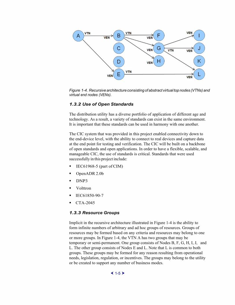
Figure 1-4. Recursive architecture consisting of abstract virtual top nodes (VTNs) and virtual end nodes (VENs).
1.3.2 Use of Open Standards
The distribution utility has a diverse portfolio of application of different age and technology. As a result, a variety of standards can exist in the same environment. It is important that these standards can be used in harmony with one another.
The CIC system that was provided in this project enabled connectivity down to the end-device level, with the ability to connect to real devices and capture data at the end point for testing and verification. The CIC will be built on a backbone of open standards and open applications. In order to have a flexible, scalable, and manageable CIC, the use of standards is critical. Standards that were used successfully in this project include:
IEC61968-5 (part of CIM)
OpenADR 2.0b
DNP3
Volttron
IEC61850-90-7
CTA-2045
1.3.3 Resource Groups
Implicit in the recursive architecture illustrated in Figure 1-4 is the ability to form infinite numbers of arbitrary and ad hoc groups of resources. Groups of resources may be formed based on any criteria and resources may belong to one or more groups. In Figure 1-4, the VTN A has two groups that may be temporary or semi-permanent. One group consists of Nodes B, F, G, H, I, J, and L. The other group consists of Nodes E and L. Note that L is common to both groups. These groups may be formed for any reason resulting from operational needs, legislation, regulation, or incentives. The groups may belong to the utility or be created to support any number of business modes.
1-5

1.3.4 Enterprise Service Bus
An enterprise service bus (ESB) provides an event-driven messaging engine. For the purposes of this project, the team will use an open source ESB from Glashfish. This messaging engine provides an abstraction layer that allows messages to be passed between systems without the need for writing application and data model specific code greatly simplifying development and implementation. Internal to the utility, the ESB facilitates communication between enterprise systems and provides services such as guaranteed delivery and audit trails of messages. External to the utility, the ESB acts as a gateway to third parties that take advantage of the recursive architecture and group technology. The ESB allows for the flow of both operational and financial transactions to third party resource aggregators. The ESB will allow essentially infinite scalability of the CIC.
1.3.5 Open Applications
EPRI has a history of developing open source applications. This project included an open source semantic standard test harness (OpenSSTH), open source demand response application server (OpenDRAS), and an open source distributed energy resource management system (OpenDERMS). These applications are improvements to existing EPRI technology and play primary roles in enabling diverse, clean energy integration. These tools provide open standards-based communication interfaces both upstream and downstream.
The OpenDRAS is an open source reference implementation of the OpenADR 2.0 standard (www.openadr.org) developed by EPRI to test a number of funded projects for the last several years. The OpenDERMS is an open source application that is meant to send and receive CIM messages as well as control protocols (such as DNP3) from devices and so, act as a virtual top node and virtual end node in the EPRI recursive architecture.
1.3.6 Open Semantic Standard Test Harness (OpenSSTH)
The experiment used an open source, semantic standard test harness that was first developed by EPRI in 2011 and improved upon in this project. This standard will be deployed as the infrastructure to support certification and integration testing of semantic standards, primarily CIM (Common Information Model) and MultiSpeak®. These types of testing against the standard are mandatory for commercialization of projects to support the integration of both DR and DER.
1-6

Section 2: Laboratory Testing and Result Highlights
Figure 2-1 ADMS GIS view of a fictitious test feeder on a generic land base.
Figure 2-2. Geo-schematic view of fictitious test feeder.
2-1

2.1 Feeder-Level Voltage Management
The goal of this test case was to prove that power quality could be controlled by using multiple resources to optimize voltage throughout the feeder. The ADMS control of the generation and load resources was solely through the OpenDERMS and OpenDRAS applications while the voltage regulator was controlled by the ADMS. The control actions of OpenDERMS and OpenDRAS were based on analysis of ADMS measured data. The ADMS provided current network state, including voltage values and alarms, and leveraged real-time data along with state estimation and load flow analyses.
The one-line diagram in Figure 1-1 was used to create a fictitious feeder diagram in ADMS, shown in Figure 2-1 and Figure 2-2. In the first scenario of the experiment, an overvoltage situation was produced when the voltage at the head of the feeder was manually set to 290V. The output of the inverters was manually increased, resulting in a high voltage along the feeder. The ADMS was told to force a solution involving only non-utility assets. The ADMS responded by increasing loads in both load groups (including the variable load). At the same time, DER Group B was told to consume Var. This resulted in reducing the voltage all along the feeder to within standard.
In the second part of this experiment, the ADMS was to manage all resources (utility and non-utility) to maintain the voltage to within standard. The experimental assumption was that communications was lost and then restored to feeder regulation devices. The variable and switched loads were returned to their original state. The utility removed all controls from the DER. Finally, the ADMS controls the voltage via the voltage regulator by removing the “Do Not Operate” tag. In this scenario, voltage violations remained at some locations as seen in Figure 2-3.
Figure 2-3. Violation Report -- consumers with overvoltage.
2-2
2.2 Protecting and Optimizing the Use of Grid Assets
2.2.1 Goal
This test case was to optimize the use of distribution transformers while protecting them from overload (load or generation). For example, one scenario is that transformers failing prematurely due to EV clustering in neighborhoods. All control actions on OpenDERMS and OpenDRAS will be based on analysis of measurement data. ADMS provided generator injection values and issued commands for OpenDERMS and OpenDRAS.
2.2.2 Results
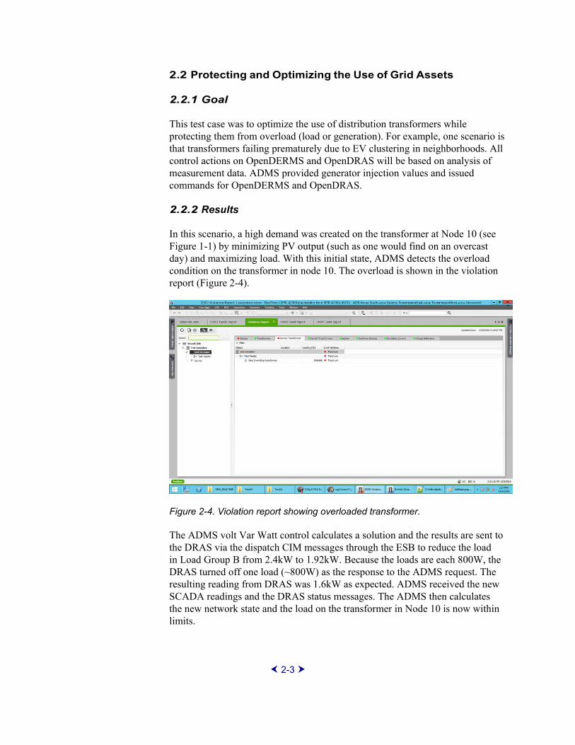
In this scenario, a high demand was created on the transformer at Node 10 (see Figure 1-1) by minimizing PV output (such as one would find on an overcast day) and maximizing load. With this initial state, ADMS detects the overload condition on the transformer in node 10. The overload is shown in the violation report (Figure 2-4).
Figure 2-4. Violation report showing overloaded transformer.
The ADMS volt Var Watt control calculates a solution and the results are sent to the DRAS via the dispatch CIM messages through the ESB to reduce the load in Load Group B from 2.4kW to 1.92kW. Because the loads are each 800W, the DRAS turned off one load (~800W) as the response to the ADMS request. The resulting reading from DRAS was 1.6kW as expected. ADMS received the new SCADA readings and the DRAS status messages. The ADMS then calculates the new network state and the load on the transformer in Node 10 is now within limits.
2-3

2.3 Transactive Energy
2.3.1 Goal
This use case will demonstrate the operation of the Volttron software platform in conjunction with the Intwine ICG in the HEM application. When an OpenADR 2.0b signal is received by the home energy management system (HEMS), each of the load control agents evaluates its current and anticipated states. These are compared to the customer preferences (the customer can choose which asset to use under what conditions) and the HEMS decides whether to participate in the event. The HEMS also decides how the premise participates in the event.
2.3.2 Results
In the INTEGRATE project, Intwine tested the OpenADR2.0b system and all of the CTA-2045 equipped devices responded as expected. The interface between a simulated home and a utility broker was also tested. All of the various CTA-2045 compatible loads behaved as expected based on price signals. When the homeowner’s preferences were changed to be more price conscious, more load was shed. When the load was unconstrained, the homeowner’s desired consumption was met.
2.4 VAR Support for Transmission
2.4.1 Goal
This test case was to optimize the use of distribution network resources in order to provide Var support for the transmission network.
2.4.2 Results
A request was made to increase the VAR output to the maximum allowable by operating the volt/watt/VAR control in the Schneider ADMS. Through trial and error, it was found that DER Group A could be expected to provide 3 kVAR and DER Group B could be expected to provide 1 kVAR. Using the DER groups, the voltage was dropped along the feeder as before. The VAR amounts were requested, and the resulting reverse, reactive power was produced.
2-4
Section 3: Conclusion and Analysis 3.1 Value of ESIF
The facilities and personnel of ESIF were critical to the success of this project. ESIF was superbly constructed for use by the industry in just these sorts of projects. Though EPRI also has a laboratory, the ease of configurability of the ESIF lab made conducting the INTEGRATE project much simpler than could have been done at the EPRI laboratory.
The people at ESIF were very knowledgeable and were great to work with. They were clearly dedicated to the success of the project and provided insights and capabilities where we clearly had gaps.
3.2 Impact on Stakeholders
In the INTEGRATE Task 2 experiment, the point of view from the prosumer, the utility, and the market were all considered. Without going into rates and incentives, the INTEGRATE project demonstrated how a highly flexible distribution feeder could operate. The technology demonstrated that utility assets could be protected, power conserved through volt/Var optimization, price signals affecting customer participation in the market and the transmission grid supported. These remarkable results were made possible by a relatively small group of standards described next.
Also demonstrated was the use of resource “groups” and an architecture that enables new business models through the creation of virtual power plants and DR aggregators. This architecture is also ideal for enabling transactive energy markets, trading of energy using Blockchain, and smart contracts.
3.3 Standards Assessment
3.3.1 OpenADR 2.0b
The OpenADR 2.0b demand response standards were created by the OpenADR Alliance based on the OASIS Energy Interoperation Standard and intended to guide users in the creation of schema, payloads, and test plans. This widely accepted standard was used in INTEGRATE to speak to loads through communications modules that adhered to the CTA-2045 standard mentioned below. Two things were unique to INTEGRATE: 1) the OpenADR messages were used for grid stability purposes instead of what they were intended for
3-1

economic dispatch of load management events. 2) the OpenADR 2.0b standard was extended to allow the ability to turn loads on, if additional loads were required to achieve a stable grid. As might be expected with a mature standard, no issues were found with OpenADR 2.0b. There were issues found between the EPRI and Intwine implementations. The pool pump experienced some issues with the initial bits sent by the two controllers but this was a problem with the code at the pump. A code change was required in the EPRI OpenADR implementation to prevent the pool pump from malfunctioning.
3.3.2 CTA-2045
The CTA-2045 standard allows for a request to be made for device behavior changes. The standard actually governs two form factors (one AC and one DC) for attachment to devices and serves as a replaceable communications bridge that is agnostic of the device. Each utility can use its communications choice and does not have to specify to the vendor what must be supported to be sold in its service territory. Because CTA-2045 is a connection standard, what mattered was the ability to make and maintain contact with the end device. We often had issues with that, requiring multiple re-seating of the modules. The lack of any visible indication of connectivity exacerbated this issue.
3.3.3 IEC 61850-90-7 and IEC 61850-7-420
Over the four-year period from 2008 to 2012, EPRI worked with the U.S. Department of Energy, Sandia National Laboratories, and the Solar Electric Power Association to develop these standards. These standards are for the messaging syntax for communication to smart inverters.
3.3.4 Distributed Network Protocol: DNP3
DNP3 was used in the INTEGRATE project to talk to the capacitor bank and the voltage regulator directly from the ADMS. DNP3 is a very mature and powerful standard. With this power comes complexity, and use of the DNP3 standard depends on sending values to various “points” on the device. The configuration of these points is often misinterpreted in the setup; such was the case in the experiments. The configuration of the points needed to be done by a service person from the manufacturer of the voltage regulator controller.
3.3.5 Volttron
Volttron, in the context of the INTEGRATE experiment is a “behind the meter” standard allowing for agent based programming. The result is the ability for the homeowner to have extensive control of when and how they participate in the demand response market. The homeowner could place constraints on what devices participate and under what terms. The purpose of the third experiment in Task 2 was to demonstrate this.
3-2

3.3.6 Common Information Model – IEC 61968
For the last four years, EPRI has been working with utilities, DMS software providers, DER management experts, inverter manufacturers, universities and researchers worldwide to produce a CIM standard for control over DER through a DERMS-type product. The results have been published by EPRI and made publicly available1. The participants identified a range of useful functions for enterprise integration of DER and prioritized these functions in terms of value to the industry. The results of this process established the messages used in the current project.2,3 The top 5 priorities were determined by the workshop included:
DER status monitoring
DER capabilities discovery
Real power dispatch
Reactive Power Dispatch
DER forecast
These functions, along with DER group creation and maintenance functions were tested in INTEGRATE Task 2. Very few changes were required to the actual messages although the OpenDERMS software needed some modifications to scale the values being passed to the correct units.
3.4 Key Takeaways
Open standards are sufficient to enable groups of connected devices to bemonitored and managed effectively.
A recursive architecture is one way to create a flexible solution to manage anddispatch DER and DR resources.
Aggregating software packages such as OpenDERMS and OpenDRAS canbe used by an ADMS to control groups of resources without any knowledgeof the resources they represent.
DER and DR can be coordinated using a commercial ADMS packagethrough the use of resource groups.
1 Collaborative Initiative to Advance Enterprise Integration of DER: Workshop Results. EPRI, Palo Alto, CA: 2012. 1026789. 2 Enterprise Integration Functions for Distributed Energy Resources: Phase 1. EPRI, Palo Alto, CA: 2013. 3002001249. 3 Enterprise Integration Functions Test Plan for Distributed Energy Resources, Phase 1. EPRI, Palo Alto, CA: 2014. 3002004681.
3-3

Section 4: Future Research There are four primary areas where this research could be extended:
A project of similar complexity on an actual medium voltage distribution circuit.
A more complicated (multi-group, multi-layered) project on the grid simulator used in this project.
Using the learnings and equipment developed here in the SHINES4 project.
Exploring using the test equipment and communications architecture in a Blockchain and smart contracts project.
4 Grid Interactive Microgrid Controllers and the Management of Aggregated Distributed Energy Resources (DER): Relationship of Microgrid Controller with Distributed Energy Resource Management System (DERMS) and Utility Distributed Management System (DMS). EPRI, Palo Alto, CA: 2015.3002007067
4-1

The Electric Power Research Institute, Inc. (EPRI, www.epri.com) conducts research and development relating to the generation, delivery and use of electricity for the benefit of the public. An independent, nonprofit organization, EPRI brings together its scientists and engineers as well as experts from academia and industry to help address challenges in electricity, including reliability, efficiency, affordability, health, safety and the environment. EPRI members represent 90% of the electric utility revenue in the United States with international participation in 35 countries. EPRI’s principal offices and laboratories are located in Palo Alto, Calif.; Charlotte, N.C.; Knoxville, Tenn.; and Lenox, Mass.
Together...Shaping the Future of Electricity
Program:
Information and Communication Technology
© 2017 Electric Power Research Institute (EPRI), Inc. All rights reserved. Electric Power Research Institute, EPRI, and TOGETHER...SHAPING THE FUTURE OF ELECTRICITY are registered service marks of the Electric Power Research Institute, Inc.
3002011500
Electric Power Research Institute 3420 Hillview Avenue, Palo Alto, California 94304-1338 • PO Box 10412, Palo Alto, California 94303-0813 USA
800.313.3774 • 650.855.2121 • [email protected] • www.epri.com