national science foundation - governmentattic.org
TRANSCRIPT

Description of document: National Science Foundation (NSF) Documents Concerning the Arecibo Radio Observatory Response Plan
Requested date: 19-November-2020 Release date: 26-February-2021 Posted date: 15-March-2021 Source of document: National Science Foundation
Attn: FOIA Officer 2415 Eisenhower Avenue Alexandria, Virginia 22314 Fax: (703) 292-9041 Email: [email protected]
The governmentattic.org web site (“the site”) is a First Amendment free speech web site and is noncommercial and free to the public. The site and materials made available on the site, such as this file, are for reference only. The governmentattic.org web site and its principals have made every effort to make this information as complete and as accurate as possible, however, there may be mistakes and omissions, both typographical and in content. The governmentattic.org web site and its principals shall have neither liability nor responsibility to any person or entity with respect to any loss or damage caused, or alleged to have been caused, directly or indirectly, by the information provided on the governmentattic.org web site or in this file. The public records published on the site were obtained from government agencies using proper legal channels. Each document is identified as to the source. Any concerns about the contents of the site should be directed to the agency originating the document in question. GovernmentAttic.org is not responsible for the contents of documents published on the website.

NATIONAL SCIENCE FOUNDATION 2415 Eisenhower Avenue Alexandria, Virginia 22314
OFFICE OF THE GENERAL COUNSEL
Telephone (703) 292-5065 FAX (703) 292-9483
February 26, 2021
Via email
Case #2021-45F
This is a partial response to your November 19, 2020 emailed Freedom of Information Act (FOIA) request to the National Science Foundation (NSF) for the following records pertaining to Arecibo Observatory, specifically:
1) The technical/engineering assessment of the Arecibo Observatory Telescope in 2020.
2) a copy of the decisional document(s) or memorandum(s) making the determination to scrap the Arecibo Observatory Telescope.
3) A copy of the Analysis of Alternatives regarding the Arecibo Observatory Telescope.
4) A copy of letter correspondence with the University of Central Florida regarding the decision to scrap the Telescope. You may limit this request to documents between August 1, 2020 and November 19, 2020.
Enclosed is the Response Plan to the Auxiliary Cable Failure at the Arecibo Observatory that I interpreted as being responsive to item #3 of your request. Personal information (signatures) has been withheld wherever it appears under the privacy protection of Exemption (b)(6) of the FOIA. I am also enclosing some links to the public website that may be useful.

http://www.naic.edu/~phil/hardware/telescope/auxmain200810/auxmain4.html
http://www.naic.edu/~phil/hardware/telescope/auxmain200810/auxmain4photos.html
We will continue processing the remainder of your request and update when records are received.
Your right of administrative appeal is set forth in Section 612.9 of the NSF FOIA regulation (copy enclosed). Your appeal must be postmarked or electronically transmitted within 90 days of the date of the response to your request.
If you need any further assistance or would like to discuss any aspect of your request, please do not hesitate to contact our FOIA Public Liaison at 703-292-8060. Additionally, you may contact the Office of Government Information Services (OGIS) which was created to offer mediation services to resolve disputes between FOIA requesters and Federal agencies as a non-exclusive alternative to litigation. Using OGIS services does not affect your right to pursue litigation. If you are requesting access to your own records (which is considered a Privacy Act request), you should know that OGIS does not have the authority to handle requests made under the Privacy Act of 1974. You may contact OGIS in any of the following ways:
National Archives and Records Administration Office of Government Information Services 8601 Adelphi Road - OGIS College Park, MD 20740-6001 E-mail: [email protected] Web: https://archives.gov/ogis Telephone: 202-741-5770 Facsimile: 202-741-5769 Toll-free: 1-877-684-6448 There is no fee for FOIA services in this instance in accordance with 5 U.S.C. 552(a)(4)(A)(i) et seq.
Sincerely,
/s/
Sandra Evans FOIA/Privacy Act Officer Enclosures

WJE September 1, 2020
Mr. Ramon Lugo Principal Investigator
University of Central Florida Florida Space Institute 12354 Research Parkway Partnership 1 Building, Suite 214 Orlando, FL 32826-0650
Response Plan for the Arecibo Observatory Cable Failure
Dear Mr. Lugo:
W iss, Janney, Elstner Associates, Inc.
330 Pfingsten Road
Northbrook, Illinois 60062
847.272.7400 tel
www.wje.com
As outlined in our proposal dated August 20, 2020, Wiss, Janney, Elstner Associates, Inc. (WJE) is pleased
to provide the attached Response Plan for the Auxi liary Cable Fai lu re at the Arecibo Observatory. This plan
was developed using the information provided to WJE to-date including our conference call with the
project team on August 31, 2020. We believe we have structured the plan and its associated tasks so that
the investigative and repai r work can be completed timely and safely. WJE will lead the overall forensic
investigation of the failure and the visual condition assessment of the remaining cables. WJE wil l also be
responsible for working with other parties to assess and maintain structure stability at the various stages
of the investigative and restorative work. These responsibilities have been clarified in the proposed plan.
We are available to discuss and answer questions as needed.
Sincerely,
(b) (6)
~
(b)(6)
y Principa l
Attachment
Brian J. Santosuosso Principal
Atlanta I Austin I Boston I Chicago I Cleveland I Dallas I Denver I Detroit I Honolulu I Houston I Indianapolis London I Los Angeles I Minneapolis I New Haven I Northbrook (HQ) I New York I Philadelphia I Pittsburgh I Portland
Princeton I Raleigh I San Antonio I San Diego I San Francisco I Seattle I South Florida I Washington, DC

WJE September 1, 2020
RESPONSE PLAN FOR THE AUXILIARY CABLE FAILURE AT THE ARECIBO OBSERVATORY
Introduction
As requested, Wiss, Janney, Elstner Associates, Inc. (WJE) performed a preliminary review of information
provided by your office to-date related to the recent auxiliary suspension cable failure at the Arecibo
Observatory. The purpose of this review was to become familiar with current conditions at the
Observatory and develop a plan for pursuing a forensic investigation of the failure, performing a cond ition
assessment of remaining cable elements, and implementing measures as needed to maintain stability of
the suspended platform during these efforts and while repairs designed by others are implemented to
restore normal observatory operations. WJE will lead the overal l forensic investigation of the failure and
the visual condition assessment of the remaining cables. WJE will also be responsible for working with
other parties to assess and maintain structure stabil ity at the various stages of the investigative and
r-estorative work.
Background
Accident Description
On August 10, 2020, a structural cable failed at 2:35 am during normal observatory operations. The failed
cable was a primary component of the system used to suspend a large, steel-framed platform (Feed
Platform) above the telescope reflector dish. The failed cable was one of twelve auxiliary cables installed as
part of a 1992-designed modification to the observatory. As a result of the cable failure, the supported
Gregorian dome and many reflector panels were damaged. The observatory is no longer operating.
Document Review
We have received many documents related to the facility and the failure, and we anticipate receiving many
more. The information received and reviewed to date has enabled us to develop the response plan
outl ined in this letter.
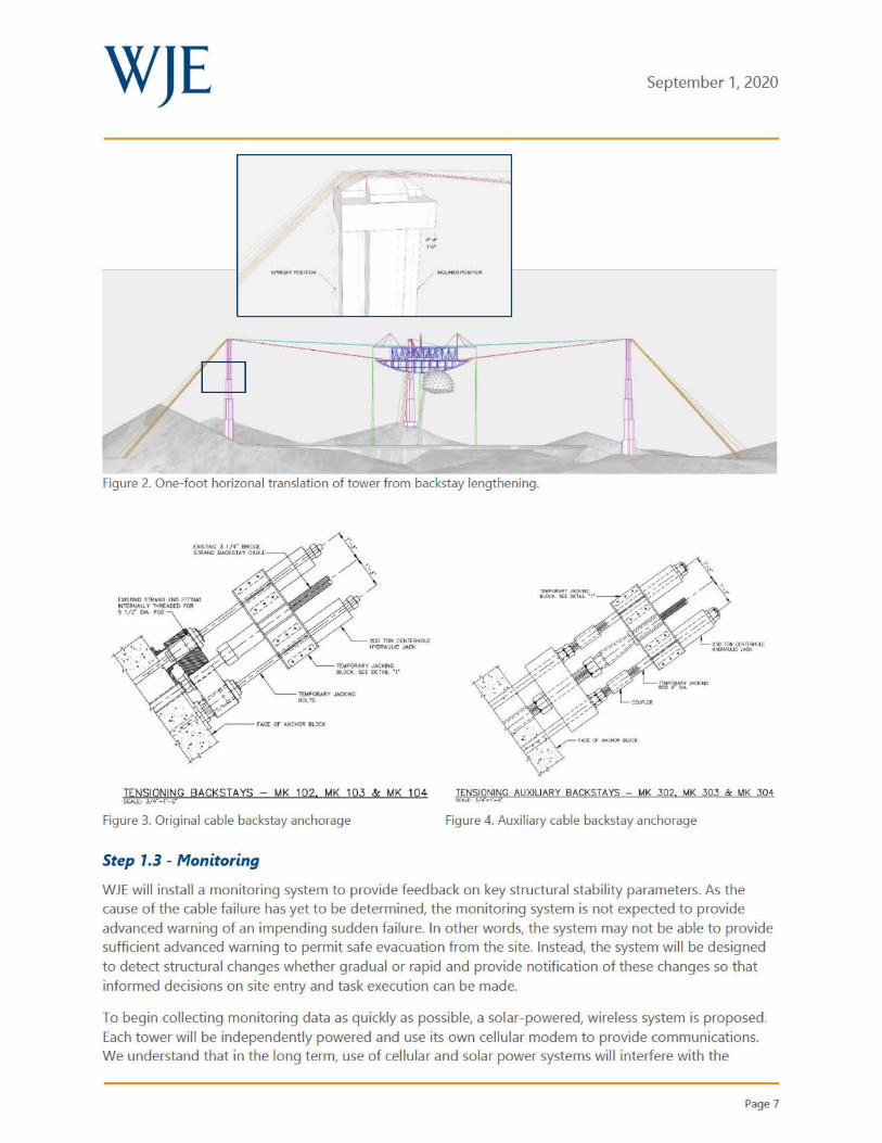
According to drawings provided for our review, the subject structure includes the following primary
components (refer to Figure 1 ):
• A suspended, steel-framed platform (Feed Platform, in blue)
o Shaped as an equilateral triangle in plan, with each side measuring 216 feet
o Suspended from three sets of wire ropes; each set aligned with the bisector of a corner
angle
o One corner angle bisector points north and is given a position designation of 12 (as in 12
a-clock), while the other two bisectors point south east (position 4, as in 4 o-clock), and
southwest (position 8, as in 8 o-clock)
o Substantia lly modified in 1992 via addition of equipment and additional structural
elements
• Wire suspension cables (in red and cyan)
Page 1

WJE September 1, 2020
o One set corresponding to each corner of the Feed Platform, generally aligned with the
corner's bisector, so that there is one set of cables at 12 a-clock, one set at 4 a-clock, and
one set at 8 a-clock
o Each set contains 4 original (1960 construction) cables (red), each 3.0-inch diameter with a
breaking strength of about 600 tons, extending about 575 feet from a corner of the Feed
Platform to a support tower, at a vertical angle of about 12.8 degrees
o Each set contains 2 auxiliary (1992 construction) cables (cyan), each 3.25-inch diameter
with a breaking strength of about 720 tons, extending about 700 feet from a point on the
side of the Feed Platform to the same tower that supports the original cables, at a vertical
angle of about 10.5 degrees
• Support towers (in purple)
o One tower for each set of suspension cables (designated T12, T8 and T 4 corresponding to
the clock positions of each cable set)
o The tops of the towers are at a common elevation that is about 100 feet above the top
chords of the Feed Platform main trusses
o Reinforced concrete, cruciform cross-section
o Cross-section varies via setbacks at various elevations
o Foundation consists of reinforced concrete pad bearing on natura l rock
o Suspension cables are anchored to the top of the tower
o Inward pull of suspension cables is balanced by a set of backstay cables that are also
attached to the top of the tower
• Backstay cables (in orange and yellow)
o One set for each tower
o Aligned rad ially with suspension cables, but on the opposite side of the tower
o Each set contains 5 orig inal (1960 construction) cables (orange), each 3.25-inch diameter
with a breaking strength of about 700 tons; and 2 auxiliary cables (1992 construction in
yellow), each 3.625-inch diameter, with a breaking strength of about 880 tons
o Each set of backstay cables attaches to a single reinforced concrete anchorage set in
natural rock; the d istance of the anchorage from the base of the corresponding tower and
the angle of the backstay set vary as follows: T12: anchorage is 380 feet from tower, and
cables are at an angle of 36 degrees from horizontal; T8: anchorage is 390 feet from tower
and cables are at an angle of 26 degrees from horizontal; T4: anchorage is 455 feet from
tower, and cables are at an angle of 37 degrees from horizontal.
• Hold down cables (in green)
o Three pairs of cables, each of which is 1.5-inch diameter with a breaking strength of about
150 tons
o Each pa ir connects an outrigger aligned with a corner of the Feed Platform to an anchorage located directly below (i.e., the cables are vertical)
o The as-designed tension in each hold down cable was 24 kips under gravity load only conditions with a maximum "operational" load of 59 kips
Page 2

WJE September 1, 2020
On August 10, 2020, the north auxiliary suspension cable in the 4 a-clock set failed . According to
documents provided for our review, the mode of failure involved the tower end separating from the zinc
fi lled spelter socket in the clevis that connected the cable to Tower T4.
An event summary document we were given access to on August 26, 2020 summarized information
concerning various operational conditions shortly before and shortly after the failure. According to this
document, the total tension in the ho ld down cables was about 95 kips just before the event and about
110 kips shortly thereafter. This document also noted that, shortly after the incident, the remote
controlled jacks on the hold down cables were moved to their total stroke such that the total tension in
the cables was reduced to around 40 to 48 kips, concentrated at the 4 a-clock corner of the Feed Platform.
Figure 1. Arecibo Observatory with components color-coded.
RESPONSE PLAN
Based on our review of available documentation and an August 31, 2020 conference call with parties
involved with this indicent, we developed a plan for investigating the failure and restoring the affected
Feed Platform suspension system to a serviceable state. We have identified three, somewhat concurrent
tasks under which the work will be completed. The various steps in this plan and the supporting rationale
are summarized below. Given the fact that we are receiving additional information almost daily and that
we have yet to visit the site, this plan is necessarily general in scope and will be supplemented with greater
detail as work progresses.
Page 3

WJE September 1, 2020
Task 1 - Initial Measures
Step 1. 1 - Initial Assessment
The load in the failed cable was likely much less than its original capacity. This suggests that the cables
have been subjected to mechanisms (e.g., corrosion, fatigue) that have significantly reduced the ir
strengths. Until the effects of such mechanisms can be reliably quantified, reliable analytical
determinations of current cable capacities are not possible. In contrast, reasonably accurate capacities of
platform framing members and connections can be established using analytical methods. We understand
that others will be responsible for developing an analytical model that will be used to quantify demands
in cable and platform elements at any particular stage in the investigation/restoration process, and that
they will also provide capacities for platform members and connections.
When considering possible courses of action, it is helpfu l to have some understanding concerning the
stability associated with existing conditions. In this context, the following facts are relevant:
1. The design capacities of the remaining 4 a-clock suspension cables (and all other suspension and
backstay cables) are much greater than the current demands. In fact, the as-new capacity of the
original set of 4 suspension cables is about 150 percent of the current tension in each suspension
group. This means that even with both auxiliary cables lost, the original cable set wou ld have to
be substantially compromised in order for a cable group to fail under gravity loading.
2. During the loss of the failed cable, the structure was ab le to sustain the associated dynamic
loading without becoming unstable.
3. After the dynamic effects of the failure subsided, the demands in many elements were (and
remain) less than the peak demands sustained during the dynamic response phase.
4. The yet-to-be-determined mechanisms that led to the failure of the subject cable almost certainly
created substantially varying capacities in all auxiliary cables, which means the relative capacities
of the remaining cables are likely significantly higher than the capacity of the weakest cable (i.e.,
the one that failed).
5. After the cable failed, loading on the remaining Feed Platform suspension cables was significantly
reduced by relieving tension on the hold-down cables.
Items 1 through 4 provide subjective reasons for believing the current capacity/demand (C/D) ratios for
the primary structural elements and the suspension system as a whole are significantly greater than one
rather than just barely greater than one. The actions related in Item 5 provided a quantitative reduction in
the load carried by the suspension system of about 4 percent. Consequently, when there are no significant
loads other than gravity acting on the system, failure of additional cables in the near future is unlikely.
With this in mind, we believe that it would be appropriate to carefully remove the clevis of the failed cable,
and lower it to the ground, provided the work can be done during a period of calm weather (i.e., wind
gusts remaining below 20 mph). However, as discussed below, we believe additional measures should be
implemented before permitting access within the perimeter defined by the towers (i.e., within about 700
feet of the center of the reflector dish) and before allowing extensive work to be performed at the tops of
the towers.
A detai led model of the Feed Platform and suspension cable system is being prepared by others for the
purpose of performing the fo llowing tasks:
Page4
WJE September 1, 2020
1. Analytically evaluate the existing cond ition of the Feed Platform framing to identify members and
connections that are highly loaded.
2. Establish a benchmark estimate of element demands (truss members, cables, connections} as a
basis for comparisons with changing conditions.
3. Evaluate the effects of substantial temperature changes on key elements.
As part of the initial assessment, WJE will rely upon the model results to prioritize stabilization efforts and
establish safe procedures for beginning repa ir and investigation work.
Step 1.2 - System Load Management
Immediately after the cable failure, the suspended platform system was stable, which means the elements
comprising the system clearly had C/D ratios greater than one. Equally clear is the fact that the C/D ratios
for critical system elements need to remain greater than one if people are going to be working on the
towers and within the tower perimeter. Maintaining C/D ratios greater than one a lso mitigates risk to the
facility. WJE will oversee the efforts to manage the system loads in coordination with others.
Although the system is currently stable, time-dependent mechanisms (e.g., corrosion, fatigue} are at work,
at least some of which are reducing element capacities. The key to maintaining system stability is to keep
demands below the corresponding capacities as those capacities decrease. The previously noted reduction
in hold-down cable tension was a productive, quantifiable action in this regard.
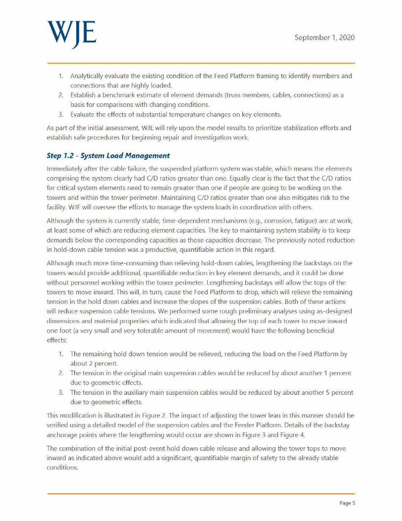
Although much more time-consuming than rel ieving hold-down cables, lengthening the backstays on the
towers would provide additional, quantifiable reduction in key element demands, and it could be done
without personnel working within the tower perimeter. Lengthening backstays wil l allow the tops of the
towers to move inward. This will, in turn, cause the Feed Platform to drop, which will relieve the remaining
tension in the hold down cables and increase the slopes of the suspension cables. Both of these actions
wi ll reduce suspension cable tensions. We performed some rough preliminary analyses using as-designed
dimensions and materia l properties which indicated that allowing the top of each tower to move inward
one foot (a very smal l and very tolerable amount of movement) would have the following beneficial
effects:
1. The remaining hold down tension would be relieved, reducing the load on the Feed Platform by
about 2 percent.
2. The tension in the original main suspension cables would be reduced by about another 1 percent
due to geometric effects.
3. The tension in the auxi liary main suspension cables would be reduced by about another 5 percent
due to geometric effects.
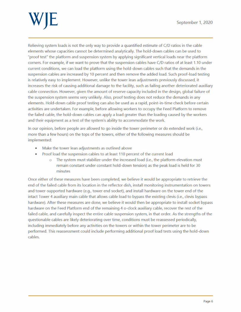
This modification is illustrated in Figure 2. The impact of adjusting the tower lean in this manner should be
verified using a detailed model of the suspension cables and the Feeder Platform. Details of the backstay
anchorage points where the lengthening would occur are shown in Figure 3 and Figure 4.
The combination of the initial post-event hold down cable release and allowing the tower tops to move
inward as indicated above would add a significant, quantifiable margin of safety to the already stable
conditions.
Page 5
WJE September 1, 2020
Relieving system loads is not the only way to provide a quantified estimate of C/D ratios in the cable
elements whose capacities cannot be determined analytical ly. The hold-down cables can be used to
"proof test" the platform and suspension system by applying significant vertical loads near the platform
corners. For example, if we want to prove that the suspension cables have C/D ratios of at least 1.10 under
current conditions, we can load the platform using the hold-down cables such that the demands in the
suspension cables are increased by 10 percent and then remove the added load. Such proof-load testing
is relatively easy to implement. However, unlike the tower lean adjustments previously discussed, it
increases the risk of causing additional damage to the facility, such as failing another deteriorated auxiliary
cable connection. However, given the amount of reserve capacity included in the design, global failure of
the suspension system seems very unlikely. Also, proof testing does not reduce the demands in any
elements. Hold-down cable proof testing can also be used as a rapid, point-in-time check before certain
activities are undertaken. For example, before allowing workers to occupy the Feed Platform to remove
the fai led cable, the hold-down cables can apply a load greater than the loading caused by the workers
and their equipment as a test of the system's ability to accommodate the work.
In our opinion, before people are allowed to go inside the tower perimeter or do extended work (i .e.,
more than a few hours) on the tops of the towers, either of the following measures should be
implemented:
• Make the tower lean adjustments as outlined above
• Proof load the suspension cables to at least 110 percent of the current load
o The system must stabilize under the increased load (i.e., the platform elevation must
remain constant under constant hold-down tension) as the peak load is held for 30
minutes
Once either of these measures have been completed, we believe it would be appropriate to retrieve the
end of the failed cable from its location in the reflector dish, install monitoring instrumentation on towers
and tower-supported hardware (e.g ., tower end socket), and install hardware on the tower end of the
intact Tower 4 auxiliary main cable that allows cable load to bypass the existing clevis (i.e., clevis bypass
hardware). After these measures are done, we believe it would then be appropriate to install socket bypass
hardware on the Feed Platform end of the remaining 4 a -clock auxiliary cable, recover the rest of the
failed cable, and carefully inspect the entire cable suspension system, in that order. As the strengths of the
questionable cables are likely deteriorating over time, conditions must be reassessed periodically,
including immediately before any activities on the towers or within the tower perimeter are to be
performed. This reassessment could include performing additional proof load tests using the hold -down
cables.
Page 6
WJE
""'
D
Figure 2. One-foot horizonal translation of tower from backstay lengthening.
OOS ThO URAND OIi) F'ITTINO INT'EJh,h\U. Y -,.,REAOCD ,ore 5 1/2" Ct'-. AOO
200 TCH COi'!£ OU: tl"!tlAA IILIC J,l.CIC
TEW?OAAJIIY JACKlt.C 9t.OCK. SEE D(fAll ·1·
TUIP(IIA..rrJM:X.Nti 11.0CK. !EC Cl[Tt,L • 1•
.. .,.,..
September 1, 2020
~~~9~t~G BACKSTAYS - MK 102, MK 103 & MK 104 ;iJ.,.~'9_!'!~~.G AUXILIARY BACKSTAYS - MK 302 MK 303 & MK 304
Figure 3. Original cable backstay anchorage Figure 4. Auxiliary cable backstay anchorage
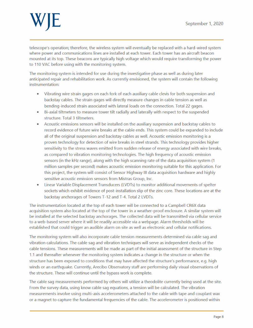
Step 1.3 - Monitoring
WJE will install a monitoring system to provide feedback on key structural stability parameters. As the cause of the cable failure has yet to be determined, the monitoring system is not expected to provide advanced warning of an impending sudden failure. In other words, the system may not be able to provide sufficient advanced warning to permit safe evacuation from the site. Instead, the system will be designed to detect structural changes whether gradual or rapid and provide notification of these changes so that informed decisions on site entry and task execution can be made.
To begin collecting monitoring data as quickly as possible, a solar-powered, wireless system is proposed. Each tower will be independently powered and use its own cellular modem to provide communications. We understand that in the long term, use of cellular and solar power systems will interfere with the
Page 7
WJE September 1, 2020
telescope's operation; therefore, the wireless system will eventually be replaced with a hard-wired system where power and communications lines are installed at each tower. Each tower has an aircraft beacon mounted at its top. These beacons are typically high voltage which would require transforming the power to 110 VAC before using with the monitoring system.
The monitoring system is intended for use during the investigative phase as well as during later anticipated repair and rehabilitation work. As currently envisioned, the system will contain the following instrumentation:
• Vibrating wire strain gages on each fork of each auxiliary cable clevis for both suspension and
backstay cables. The strain gages will directly measure changes in cable tension as well as
bending-induced strain associated with lateral loads on the connection. Total 22 gages.
• Bi-axial tiltmeters to measure tower tilt radially and laterally with respect to the suspended
structure. Total 3 tiltmeters.
• Acoustic emissions sensors will be installed on the auxiliary suspension and backstay cables to
record evidence of future wire breaks at the cable ends. This system could be expanded to include
all of the original suspension and backstay cables as well. Acoustic emission monitoring is a
proven technology for detection of wire breaks in steel strands. This technology provides higher
sensitivity to the stress waves emitted from sudden release of energy associated with wire breaks,
as compared to vibration monitoring technologies. The high frequency of acoustic emission
sensors (in the kHz range), along with the high scanning rate of the data acquisition system (1
million samples per second) makes acoustic emission monitoring suitable for this application. For
this project, the system will consist of Sensor Highway Ill data acquisition hardware and highly
sensitive acoustic emission sensors from Mistras Group, Inc.
• Linear Variable Displacement Transducers (LVDTs) to monitor additional movements of spelter
sockets which exhibit evidence of post-installation slip of the zinc core. These locations are at the
backstay anchorages of Towers T-12 and T-4. Total 2 LVDTs.
The instrumentation located at the top of each tower will be connected to a Campbell CR6X data acquisition system also located at the top of the tower in a weather-proof enclosure. A similar system will be installed at the selected backstay anchorages. The collected data will be transmitted via cellular service to a web-based server where it will be readily accessible via a webpage. Alarm thresholds will be established that could trigger an audible alarm on site as well as electronic and cellular notifications.
The monitoring system will also incorporate cable tension measurements determined via cable sag and
vibration calculations. The cable sag and vibration techniques will serve as independent checks of the
cable tensions. These measurements will be made as part of the initial assessment of the structure in Step
1.1 and thereafter whenever the monitoring system indicates a change in the structure or when the
structure has been exposed to conditions that may have affected the structure's performance, e.g . high
winds or an earthquake. Currently, Arecibo Observatory staff are performing dai ly visual observations of
the structure. These will continue until the bypass work is complete.
The cable sag measurements performed by others will utilize a theodolite currently being used at the site.
From the survey data, using know cable sag equations, a tension will be calculated. The vibration
measurements involve using multi-axis accelerometers attached to the cable with tape and couplant wax
or a magnet to capture the fundamental frequencies of the cable. The accelerometer is positioned within
Page 8

WJE September 1, 2020
arm's reach of the cable end. No special supplemental excitation is needed during these measurements. A
time-history waveform is generated from the data which is then analyzed using a Fast-Fourier Transform
(FFn analysis to map the frequency spectrum and extract the fundamental frequencies of the first several
modes. Based on the cable length between connections and weight per unit length of the cables, the
tension in the cable can then be calcu lated using the relationship between natural frequency, geometry,
and material properties of the cable.
Step 1.4 - Strengthening Measures
Once the tower leaning adjustments are made or the proof loading using the hold-down cab les is
completed, the monitoring systems described above are active, current cable tensions have been
calculated based on survey data, and others have completed their assessment of the platform
components, we believe it would be appropriate to install certain supplemental items. We understand that
socket bypass hardware is being designed to supplement the strengths of certain backstay cable socket
connections that have exhibited excessive zinc slippage, and these should be installed at this t ime.
Without knowing more about the existing conditions and the extent of repairs and cable replacements
being designed by others, we cannot list specific additional items that would need to be installed at this
point. If the analyses show that certain platform elements would be excessively loaded at any time during
the investigation/restoration process, this would likely be a good time to install at least some of the
corresponding strengthening measures.
Since we cannot reliably determine the strengths of cables using analysis, maintaining the integrity of the
r·emaining cables will require a combination of efforts including surveys, instrumentation monitoring, load
testing and, possibly, supplementation. For example, if the repairs being designed by others can be
installed in a manner that precludes loading cables beyond their recently demonstrated capacities (i.e.,
loads currently sustained, loads sustained just before the failure, and loads sustained during a load test
using the ho ld -down cables), there may be no need to supplement them. However, if implementing the
desired modifications will involve loading cables beyond demonstrated capacities, supplementing suspect
socketed connections might be necessary.
In our opinion, the remaining auxiliary suspender cable at Tower T4 is especially critical because it is a
more critical component of its cable group than any of the other auxiliary cables. Given the suspect nature
of the auxiliary cable socket connections, it is especially important to prevent loading this cable's clevis
socket beyond it recently demonstrated capacity.
Task 2 - Forensic Investigation
It is important to determine the cause of the cable socket failure and evaluate cond itions at the remaining
30-year old auxiliary cable connections and original main cable connections that have been in-place over
50 years. Time is of the essence as it re lates to securing and protecting important evidence associated with
the fa ilure. Metallic failure surfaces begin to immediately corrode which can hinder and complicate later
evaluations of the surfaces. In the hot, humid environment of Arecibo, corrosion is accelerated. Therefore,
every effort should be made to safely retrieve the failed spelter socket, a portion of the failed end of the
auxil iary cable, and the other socket end with a segment of cable from the site. These components should
Page9

WJE September 1, 2020
be carefully removed from the structure, prepared for shipment, and sent to a laboratory with appropriate
forensic investigation experience and the tools to carry out the required work.
The following outlines the steps to complete the failure investigation of the cable socket by WJE:
Step 2. 1 - Failed Clevis Recovery
Once Step 1.1 is complete, recovery of the failed clevis can commence. Removal of the clevis wi l I require
personnel to climb Tower T4, secure the clevis to the tower, remove the pin, and then lower the clevis to
the ground. This work will be done during low wind conditions and in accordance with a task-specific
safety plan. All personnel will have appropriate PPE and will be tied off to proper anchorages during their
ladder accent/decent and while working on the top platform. Personnel working on the top platform
should remain next to the failed socket and avoid positioning themselves in front of or below any other
live cable socket. Figure S is a long-distance view of the failed clevis.
Risks associated with failure of another cable and any ensu ing collateral damage during this activity will be
low. As previously indicated, demands on the intact cables are less than the demands sustained during
and shortly after the failure. In addition, in the unlikely event of a future cable failure, the failed unit will
not be able to contact personnel positioned on or at the base of the tower. The tower wil l remain stable
should a backstay cable failure occur. The recovered clevis, once lowered to the ground, should be stored
indoors in an environmentally controlled space.
Figure 5. Failed clevis (circled). Photo from AO.
Step 2.2 - Cable Recovery
Recovery of the fai led cable end can occur as described in Step 1.2 when suspension cable demands have
either been reduced or proof testing has shown the cables to have significant reserve capacity.
Approximately 10 feet of the failed cable including the failed end should be recovered (see Figure 6). This
will require accessing the lower portion of the primary reflector, securing the individual wires using steel
clamps (hose clamps or similar), holding the segment of cable with a material handler, cutting the cable
with an electric saw, and lowering the materia l to the ground. This work wi ll be done during low wind
Page 10

WJE September 1, 2020
conditions for the site and in accordance with a task-specific safety plan. All personnel will have
appropriate PPE. The recovered cable end should be stored indoors in an environmentally controlled
space.
Figure 6. Cable end to be recovered. Photo from AO.
Figure 7. Failed cable draped over T12 auxil iary cable. Photo from AO.
Step 2.3 - Removal of Remaining Cable and Socket
Removal of the remaining attached socket and draped length of cable can proceed after the monitoring
and socket bypass retrofits of Steps 1.3 and 1 .4 have been installed. These steps will provide further
assurance that work on and below the platform will be reasonably safe. Removal of the still-connected
socket and cable must avoid damaging the auxiliary cable from Tower T12 over which the fai led cable is
draped (see Figure 7 above). Because it is advantageous to save the socket and cable for testing, the
retrieva l effort wil l need to secure the socket and adjustment rod connection, detach the connection
assembly, lift and rotate the assembly away from the supporting cable, and lower it to the ground.
This work wi ll be done during low wind conditions for the site and in accordance with engineered and
task-specific safety plans. All personnel wil l have appropriate PPE.
Step 2.4 - Visual Examination and Materials Testing
The root cause fai lure investigation will include metallographic and fractographic examinations of the
cable wires on both sides of the fracture. Preparation of wire end surfaces will be in accordance with ASTM
E3 - Standard Guide for Preparation of Metallographic Specimens. The evaluation process will include the
following steps: 1) Visually examine by stereomicroscope the fai led wire ends, in their as-received
condition; 2) Photodocument as appropriate; 3) Perform any dimensiona l measurements considered
relevant to the investigation; 4) Further examine relevant fracture surfaces in their as-received condition by
scanning e lectron microscopy (SEM); 5) Analyze the composition of relevant fracture surface deposits and
any other features by energy d ispersive x-ray spectroscopy (EDS); 6) If necessary, clean the fracture
Page 11

WJE September 1, 2020
surfaces to enable further examination and fractography, both visual/optical and by SEM; and 7) Perform
microhardness testing of any relevant microstructural regions or features.
Wire segments will be removed from the recovered specimen for mechanical and chemical testing. The
mechanical testing in accordance with ASTM AS86 -Standard Specifications for Metallic-Coated Parallel
and Helical Steel Wire Structural Strand will confirm the tensile strength and stress at 0.7 percent
elongation, tota l elongation, ductility, weight of meta llic coating, adherence of metallic coating, and finish.
Elemental chemical analyses will be obtained using optical emission spectrometry for compositional
analysis using ASTM E415 - Standard Test Method for Analysis of Carbon and Low-Alloy Steel by Spark
Atomic Emission Spectrometry. Hardness testing (ASTM E18 - Standard Test Methods for Rockwell Hardness
of Metallic Materials and ASTM E92 - Standard Test Methods for Vickers Hardness and Knoop Hardness of
Metallic Materials) will also be performed on the wire samples.
The failed socket will be cut longitud inally to expose the interior for examination . An attempt will be made
to match up the failed wire fractures surfaces. In addition, the composition, location and thickness of the
zinc corrosion by-product will be documented for evidence of long-term separation of the core.
Environmental testing for hydrogen embrittlement will also be considered if there is evidence of hydrogen
assisted failure at the wire fractu re surfaces. This test, in accordance with ASTM A 1032 - Standard test
Method for Hydrogen Embrittlement Resistance for Steel Wire Hard-Drawn Used for Prestressed Concrete
Pipe, will provide an indication of the wire's resistance to hydrogen embrittlement when exposed to a
hydrogen-rich environment. In this case, the environmental hydrogen would be from water.
Step 2.5 - Load Testing of Spelter Socket
The removed spelter socket and connected wire rope from the Feed Platform end of the failed cable will
be carefully examined. That cable-socket assembly will then be tested to failure which if undeteriorated
and properly constructed will be in the cable. After testing, the spelter socket wedge will be sectioned and
examined for evidence of deterioration and proper wire brooming. The formerly attached segment of
cable will be sectioned in several locations to examine internal conditions and estimate remaining service
life.
Step 2.6 - Analytical Evaluations
An analytical eva luation to determine the estimated loads on the socket at the time of the failure will be
performed. If there is evidence of fatigue damage to cable components, a model capable of identifying
key dynamic characteristics may be useful.
Task 3 - Assessment and Repair
Using the findings of the laboratory and analytical studies, a determination as to the root cause of the
failure wil l be prepared. With the root cause determined, a plan to assess the remaining cables can then
be developed and executed. If an accurate assessment is not possible, then a plan to provide
supplemental connections at the socketed ends will be needed.
Page 12

WJE September 1, 2020
Step 3. 1 - Remaining Cable Condition Assessment
A detailed condition survey of the cables will be completed by WJE. The hands-on visual inspection will
include all cable ends at the anchorages, towers, and Feed Platform. A drone will be used to visually survey
the cable lengths where they are otherwise inaccessible. Should the drone images reveal a critical finding,
industrial rope access methods will be used to provide close-up inspection. This should only begin after
the failure investigation has, at a minimum, developed its preliminary findings.
Step 3.2 - Cable Replacement
We understand that various degrees of cable replacement are being considered. Given the demonstrated
variability in the capacities of the auxiliary cables and the fact that the original cables are much older, it is
important to keep tensions in existing cables below recently demonstrated capacities when working on
the system. This can be done by either load testing the system using hold-down cables before critical
steps, relieving load on the system, installing supplemental cables, or any combination of these measures.
WJE will be responsible for establishing the procedures required to maintain stability of the structure
during the replacement work. Our assessment will rely upon the analyses of others to determine member
and component forces and platform capacities at each step of the process.
Page 13