national standards commission certificate of approval no ... · 10/l/6/4 4/3/93 certificate of...
TRANSCRIPT

National Standards Commission
10/1/6A 4m93
Certificate of Approval
No 10/1/6A
Issued under Regulation 9 of the
National Measurement (Patterns of Measuring Instruments) Regulations
This is to certify that an approval for use for trade has been granted in respect of the
Email Model ELC1 LPG Driveway Flowmeter
submitted by Email Electronics 88 - 94 Canterbury Road Kilsyth VIC 3137.
NOTE: This Certificate relates to the suitability of the pattern of the instrument for use for trade only in respect of its metrological characteristics. This Certificate does not constitute or imply any guarantee of compliance by the manufacturer or any other person with any requirements regarding safety.
CONDITIONS OF APPROVAL
This approval is subject to review on or after 1/12/93. This approval expires in respect of new instruments on l/12/94.
Instruments purporting to comply with this approval shall be marked NSC No 10/1/6A and only by persons authorised by the Submittor.
. . ..I2
10/l/6/4 4/3/93
Certificate of Approval No 10/1/6A Paae 2
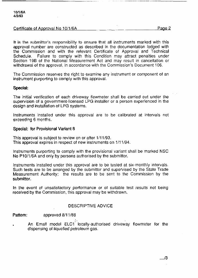
It is the Submittor’s responsibility to ensure that all instruments marked with this approval number are constructed as described in the documentation lodged with the Commission and with the relevant Certificate of Approval and Technical Schedule. Failure to comply with this Condition may attract penalties under Section 19B of the National Measurement Act and may result in cancellation or withdrawal of the approval, in accordance with the Commission’s Document 106.
The Commission reserves the right to examine any instrument or component of an instrument purporting to comply with this approval.
Special:
The initial verification of each driveway flowmeter shall be carried out under the supervision of a government-licensed LPG installer or a person experienced in the design and installation of LPG systems.
Instruments installed under this approval are to be calibrated at intervals not exceeding 6 months.
Special: for Provisional Variant 8
This approval is subject to review on or after l/l l/93. This approval expires in respect of new instruments on l/l l/94.
Instruments purporting to comply with the provisional variant shall be marked NSC No Pl0/1/6A and only by persons authorised by the Submittor.
Instruments installed under this approval are to be tested at six-monthly intervals. Such tests are to be arranged by the Submittor and supervised by the State Trade Measurement Authority; the results are to be sent to the Commission by the Submittor.
In the event of unsatisfactory performance or of suitable test results not being received by the Commission, this approval may be withdrawn.
DESCRIPTIVE ADVICE
Pattern: approved 8/l 1 I88
. An Email model ELCl”locally-authorised drivew-ay flowmeter for the dispensing of liquefied petroleum gas.
. . ..I3
lOIll6A 4m93
Certificate of Approval No 10/1/6A Page 3
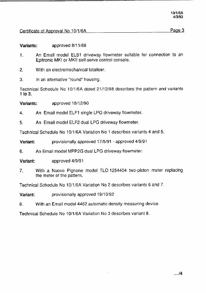
Variants: approved 8/l 1 I88
1. An Email model ELSI driveway flowmeter suitable for connection to an Epitronic MKI or MKII self-serve control console.
2. With an electromechanical totaliser.
3. In an alternative “round” housing.
Technical Schedule No 10/1/6A dated 21/l 2/88 describes the pattern and variants 1 to 3.
Variants: approved 18/l 2/90
4. An Email model ELF1 single LPG driveway flowmeter.
5. An Email model ELF2 dual LPG driveway flowmeter.
Technical Schedule No 10/1/6A Variation No 1 describes variants 4 and 5.
Variant: provisionally approved 17/5/91 - approved 4/9/91
6. An Email model MPP2G dual LPG driveway flowmeter.
Variant: approved 4/9/9 1
7. With a Nuovo Pignone model TLO 1254404 two-piston meter replacing the meter of the pattern.
Technical Schedule No 10/1/6A Variation No 2 describes variants 6 and 7.
Variant: provisionally approved 19/l O/92
8. With an Email model 4462 automatic density measuring device.
Technical Schedule No 10/1/6A Variation No 3 describes variant 8.
. . ..I4

1 O/l l6A 4f3193
Certificate of Approval No 10/1/6A Page 4
FILING ADVICE
Certificate of Approval No 10/1/6A dated 11/10/91 is superseded by this Certificate and may be destroyed. The documentation for this approval now comprises:
Certificate of Approval No 10/1/6A dated 413193 Technical Schedule No 10/1/6A dated 21112188 Technical Schedule No 10/1/6A Variation No 1 dated 13/5/91 (incl. Test
Procedure and Notification of Change) Technical Schedule No 10/1/6A Variation No 2 dated 1 l/10/91 (incl.
Notification of Change) Technical Schedule No 10/1/6A Variation No 3 dated 4/3/93 (incl. Test
Procedure Variation No 1) Test Procedure No 10/1/6A dated 21 /I 2/88 Figures 1 to 4 dated 21/l 2/88 Figures 5 and 6 dated 1315191 Figures 7 and 8 dated 1 l/l 0191 Figure 9 dated 413193
Signed and sealed by a person authorised under Regulation 9 of the National Measurement (Patterns of Measuring Instruments) Regulations to exercise the powers and functions of the Commission under this Regulation.

l0/1/6A
NATIONAL STANDARDS COMMISSION 2-l/12/88
TECHNICAL SCHEDULE No 10/1/6A
Pattern:
Submlttor:
Emall Model ELCI LPG Drlveway Flowmeter.
Emall Electronics Cnr Canterbury and Liverpool Roads KILSYTH VIC 3137.
1. Descrlptlon of Pattern
The pattern Is an Emall model ELCI drlveway flowmeter (Figure 1) for the delivery of llquefled petroleum gas of denslty 0.500 to 0.540 kg/L tat 15”0, at temperatures between - 5°C and +45”C.
The instrument Is approved for locally-authorised operation wlth maximum and mlnlmum flow rates of 60 L/min and 15 L/min respectively.
1.1 Component Structure
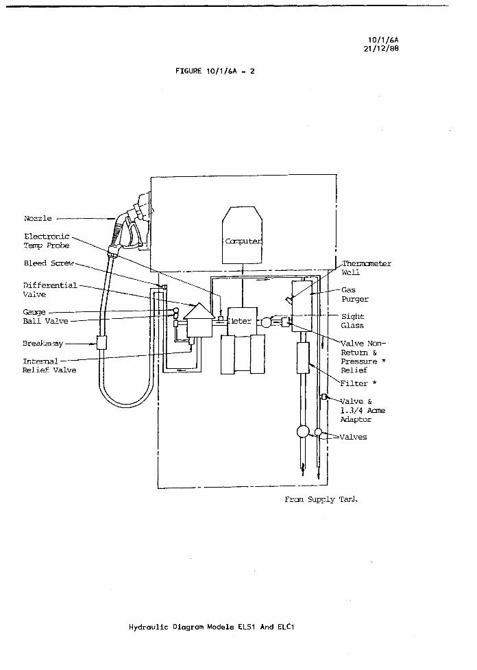
The component parts of each driveway flowmeter comprise components as detalled below. The hydraulic dlagram of the flowmeter is shown In Figure 2.
(I) Supply Tank
The supply tank Is located above the pump and where suitable pumping equipment Is provlded, the tank may be below ground.
(II) Pump
The pump is posltloned as close as possible to the supply tank and must always be In a state of flooded suction. There shall be no restrlctlve flttlngs within ten plpe dlameters of the pump Inlet. The Inlet pipe to the pump Is larger than the outlet from the pump. The external pump by-pass relief valve Is Installed In a line returnlng to the supply tank.
(III) Meter
A Schwelm two-piston Ilquefled petroleum gas meter, part number 840039 Is used.
(Iv) Gas Puraer
The meter Is protected from the measurement of vapour by COrreCt lnstallatlon and by a Neptune 32 mm gas purger (Figure 3). The waer, which incorporates a stralner and a float valve, Is vented through a non-return valve, via a vapour return llne not less than 20 mm In dlameter to the vapour space In the supply tank.
A thermometer pocket is situated In the stralner cover.
. . . . ..I2
10/1/6A 21/12/86
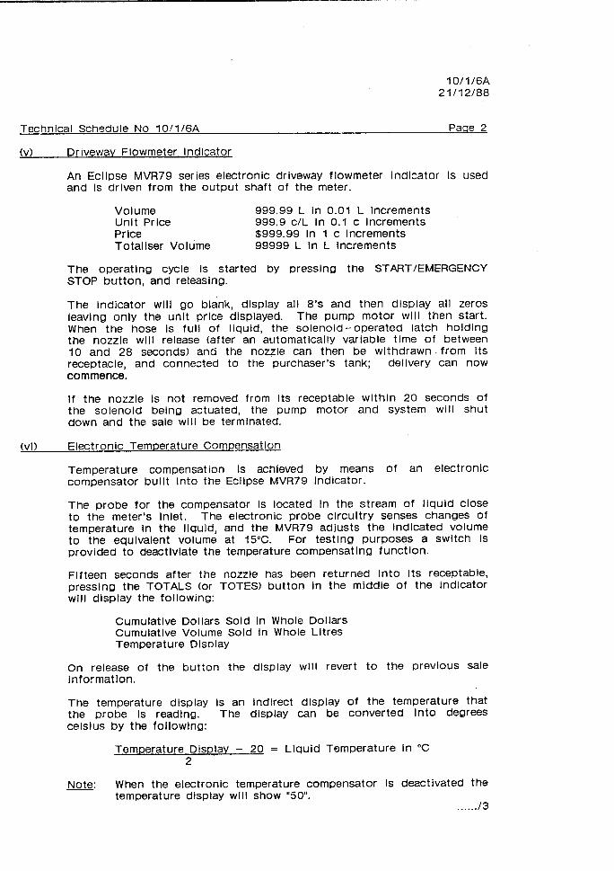
(VI Driveway Flowmeter Indicator
An Eclipse MVR79 series electronic driveway flowmeter indicator Is Used and Is driven from the output shaft of the meter.
Volume 999.99 L in 0.01 L Increments Unit Price 999.9 c/L In 0.1 c increments Price $999.99 In 1 c increments Totaliser Volume 99999 L In L Increments
The operating cycle Is started by pressing the START/EMERGENCY STOP button, and releasing.
The Indicator will go blank, display all 8’s and then display all zeros leaving only the unlt price dlsplayed. The pump motor will then start. When the hose is full of liquid, the solenoid-operated latch holding the nozzle will release (after an automatlcally variable tlme of between 10 and 28 seconds) and the nozzle can then be withdrawn .frOm Its receptacle, and connected to the purchaser’s tank; dellvery can now commence.
If the nozzle Is not removed from Its receptable within 20 seconds of the solenoid being actuated, the pump motor and system will shut down and the sale will be termlnated.
(vi) Electronic Temperature Compensation
Temperature compensation Is achieved by means of an electronic compensator built Into the Eclipse MVR79 Indicator.
The probe for the compensator Is located in the stream of liquid close to the meter’s Inlet. The electronic probe circuitry senses changes of temperature In the Ilquld, and the MVR79 adjusts the indicated volume to the equlvalent volume at 15°C. For testing purposes a switch Is provided to deactlvlate the temperature compensating function.
Fifteen seconds after the nozzle has been returned Into Its receptable, presslng the TOTALS (or TOTES) button In the mlddle of the lndlcator will display the following:
Cumulative Dollars Sold In Whole Dollars Cumulatlve Volume Sold In Whole Lltres Temperature Display
On release of the button the display will revert to the previous sale informatlon.
The temperature dlsplay Is an lndlrect display of the temperature that the probe Is reading. The display can be converted Into degrees Celsius by the followlng:
Temperature Display - 20 = Llquid Temperature In “C 2
Note. L When the electronic temperature compensator is deactivated the temperature display will show “50”.
. . . . ../3

10/1/6A 21/?2/aa
Technlcal Schedule No 10/1/6A Paae 3
(VII) Dlfferentlal Valve
A Schwelm spring-loadetl-plston pressure dlfferentlal valve maintains pressure In the meterlng chamber to prevent the formatlon of vapour.
A pressure-equallslng plpe Is connected from the dlfferentlal valve to the supply tank, through the vapour return llne from the gas purger vent (Figure 2).
An excess flow valve Is Incorporated in the outlet of the differential valve and will function at a flow rate of 80 L/min.
(VIII) Vapour lndlcator
A sight glass flow indicator Is fitted In the pipe between the gas purger and the meter so that It may be seen If vapour Is being metered.
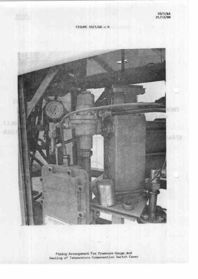
A pressure gauge Is fltted ad]acent to the pressure dlfferentlal valve (Figure 4).
(Ix) Outlet Pipe
The plpe connection from the differential valve to the hose is fitted wlth a bleed screw to enable the pressure in the hose to be lowered for reassembly of the hose break coupling.
(xl l-lose
The dispenser Is fltted with a hose of 20 mm bore, complying with the SAA code for hoses In use with liquefied petroleum gases.
The hose is supported on a hose mast and is fitted wlth a hose break coupling which will break with a loss of no more than 15 ml of liquid In the event of an excessive pull on the nozzle.
(xl) Nozzle
The nozzle used is a Gllbarco model 102 -ZVG 1.3, also known as an Elaflex, as described in the documentation of NSC approval No S158.
1.2 Marklnas
The Instrument data plate permanently flxed to the external housing of the driveway flowmeter Is marked with the fOllOwinQ:
Manufacturer’s name or mark Year of manufacture Serial number NSC approval number Maximum flow rate Mlnlmum flow rate Llquld temperature range Approved for LPG of density range Denslty for which temperature compensator Maximum operating pressure
NSC No 10/1/6A . . . . . . . . . . . . . . . L/min . . . . . . . . . . . . . . . L/min -5°C to +45-s 0.500 to 0.540 kg/L
Is set . . . .._._._..... kg/L 2450 kPa
. . . . ..I4

10/1/6A 21f12laa
1.3 Sealing
The MVR79 Indicator and meter calibration adjustments are sealed.
Alternatlvely, the computer calibration ad)ustments may be sealed. Only one side of the computer Is sealed.
The temperature compensator switch (Figure 4) and the vapour return line provided for pressure equallsatlon during testing with a pressure prover, are also sealed.
2.1 Variant 1
The Emall model ELSI LPG driveway flowmeter in which the computer of the pattern has been modlfied to facilitate connectton to an Epitronic MKI or MKll control console, I.e. remotely-authorised operation.
The operatlng sequence is similar to that for the pattern; pressing the START/EMERGENCY STOP button signals the console for authorlsatlon, after which the Cycle Is the same as for the model ELCI.
2.2 Varlant 2
With an eiectromechanlcal totallser (line model MGU). The totallser range Is 9999999 L In 1 L Increments.
2.3 Variant 3
In an aiternatlve “round” houslng. In thls case the preflx E of the model number Is replaced by M te.g. ELCI becomes MLCI).
10/1/6A
NATIONAL STANDARDS COMMISSION 2i/f2ma
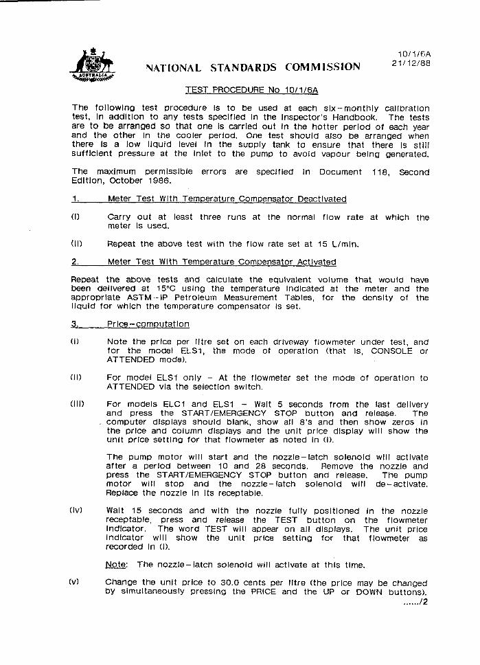
TEST PROCEDURE No 10/1/6A
The foilowlng test procedure is to be used at each slx-monthly calibration test, In addltion to any tests specified In the Inspector’s Handbook. The tests are to be arranged so that one is carried out in the hotter period of each year and the other In the cooler period. One test should also be arranged when there Is a low llquld level In the supply tank to ensure that there is stlii sufficient pressure at the Inlet to the pump to avoid vapour belng generated.
The maximum permissible errors are specified In Document 118, Second Edl tlon, October 1986.
1.
(I)
Meter Test Wlth Temperature Compensator Deactivated
Carry out at least three runs at the normal flow rate at which the meter is used.
(II) Repeat the above test with the flow rate set at 15 L/min.
2. Meter Test With Temperature Compensator Activated
Repeat the above tests and calculate the equivalent volume that would have been deilvered at 15°C using the temperature Indicated at the meter and the approprlate ASTM-IP Petroleum Measurement Tables, for the density of the liquid for which the temperature compensator is set.
3.
(I)
Price-computation
Note the price per iltre set on each driveway flowmeter under test, and for the model ELSI, the mode of operatlon (that Is, CONSOLE or ATTENDED mode).
(II) For model ELSI only - At the flowmeter set the mode of operatlon to ATTENDED via the selection switch.
(III) For models ELCI and ELSI - Wait 5 seconds from the last dellvery and press the START/EMERGENCY STOP button and release. The
I computer displays should blank, show all 8’s and then show zeros In the price and column dlsplays and the unit price display will show the unit price settlng for that flowmeter as noted In (I).
The pump motor wlli start and the nozzle-latch solenoid wlli activate after a period between 10 and 28 seconds. Remove the nozzle and press the START/EMERGENCY STOP button and release. The pump motor will stop and the nozzle-latch solenoid will de-activate. Replace the nozzle In Its receptable.
(Iv) Walt 15 seconds and with the nozzle fully positioned in the nozzle receptable, press and release the TEST button on the flowmeter indicator. The word TEST will appear on ail displays. The unit price indicator wlli show the unit price setting for that flowmeter as recorded in (I).
(VI
Note. The nozzle-latch solenoid will activate at this tlme. d
Change the unit price to 30.0 cents per litre (the price may be changed by simultaneously pressing the PRICE and the UP or DOWN buttons).
. . . . ../2

10/1/6A 21l12l88
Test Procedure No 10/1/6A Paqe 2
(VI)
(VII)
(VIII)
(ix)
(xl
(XII
(xii)
Press the UP/FAST or DOWN/SLOW TEST button to display a volume of between 7.49 iitres and 7.54 Iltres. The price will be $2.25 for 7.49, 7.50 or 7.51 Iltres, or $2.26 for 7.52, 7.53 or 7.54 iltres. if an lndicatlon beyond this volume is achieved by mistake, reset the price and volume indicators to zero by presslng the START/EMERGENCY STOP button.
Repeat test for the required number of runs.
Lift nozzle and alter the unlt price to 30.9 cents per iitre; “ERROR 2” should flash In the price indicator, Indicating a multlpllcatlon error.
Change the unlt price back to the value as recorded in (0.
Replace the nozzle and press the TEST button once and release. The word TEST on the displays will now clear. The nozzle- latch solenoid wlil de-activate.
Press the START/EMERGENCY STOP button and release. The computer will reset and the pump motor will start (the solenoid may activate). Press the START/EMERGENCY STOP button again and release, and the pump motor will stop.
Press the TOTES button on the driveway flowmeter Indicator, and check the decimal markers on the price Indicator. If they show between each figure, the batteries need immediate replacement.
For model ELSI only - Return the flowmeter to the mode recorded in (1).
4. System wlth Epitronlc MKI or MKII Consoles - MVR79 Eclipse (self-serve post-pay model) For ELSI Models Onlv
The foilowlng test procedure will check whether the system Is operating in accordance with the approved design.
Note: In order to allow the service station to continue to function while these tests are carried out, a number of the driveway flowmeters may be isolated by swltchlng to ATTENDED (MANUAL) mode at the flowmeter while the remainder are left In CONSOLE mode.
(I) Ensure that the CONSOLE mode is selected at those flowmeters to be tested.
(II) At the control console select CONSOLE (POST-PAY) mode of OperatlOn
by use of the keyswitch.
(Ill) In turn, press each STATUS button and check that all 8’s are displayed.
For one flowmeter (or more if thought to be necessary):
(Iv) Press the START/EMERGENCY STOP button and release - the AUTHORISATION light should flash at the console; authorise the flowmeter by pressing AUTHORISATION button for that flowmeter.
. . . . ../3

IQlIl6A 21/12/68
(vi)
(VII)
(VIII)
_ (Ix)
(xl
(xl 1
Deliver sufflclent liquid to cause the price and quantity Indicators on the flowmeter to move signlflcantly off zero.
Stop the pump motor by returnlng the nozzle to Its receptable.
Record the flowmeter number and the price lndlcated on the drlveway f lowmeter.
Press the START/EMERGENCY STOP button and release, and check that the price-computing lndlcator does not reset to zero and that the pump motor does not start (AUTHORISATION and STATUS lights will be Illuminated).
At the control console, press the STATUS button for the flowmeter and check the display price against the price recorded at the flowmeter (refer tvll)).
Authorlse the flowmeter by presslng the AUTHORISATION button.
After a mlnlmum of 20 seconds the STATUS light for that flowmeter will flash. Press the STATUS button; the price and volume Indicators, on both the console and the flowmeter, should zero.
National Standards Commission
TECHNICAL SCHEDULE No 10/1/6A
lOIll6A 13/5/91
VARIATION No 1
Pattern: Email Model ELCl LPG Driveway Flowmeter.
Submittor: Email Electronics Cnr Canterbury and Liverpool Roads KILSYTH VIC 3137.
1. Description of Variants
1.1 Variant 4
An Email model ELF1 single LPG driveway flowmeter (Figures 5 and 6) in which the Neptune 32 mm gas purger, the Schwelm spring-loaded-piston pressure differential valve and manual shut off valve of the pattern have been replaced by a vapour detection/elimination system comprising an Email model 001-4272 vapour detection sensor and an LPG Engineering model EVE-10 vapour elimination chamber.
The meter’ is protected from the measurement of vapour by correct installation and by the vapour detection/elimination system. The system is vented through an excess flow valve, via a vapour return line of not less than 20 mm in diameter to the vapour space in the supply tank. A temperature sensor, a thermometer pocket, a liquid level sensor, a bleed valve, and provision for a pressure gauge are incorporated into the vapour eliminator.
1 .l .l Components
-- (i) SUpplY
Instruments fitted with the vapour detection/elimination system described above may be used with the pump positioned above the supply tank provided the pump used is specifically designed for use with LPG in negative suction head installations.
The supply tank may be located above or below ground.
(ii) Solenoid Valve
A 20 mm solenoid valve located downstream of the meter maintains pressure in the metering chamber to prevent the formation of vapour. The valve is controlled by the computing indicator and by the vapour eliminator to prevent delivery during the reset cycle and when vapour has been detected.
. . ..I2

10/1/6A 13/5/91
T n’ ia
(iii)
(iv)
(VI
1.1.2
Vapour Indicator
A sight glass flow indicator is fitted in the pipework downstream of the meter.
Outlet Piping
The pipe connection from the meter to the hose is fitted with an air-operated ball valve to a positive shut-off valve, to ensure closure of the delivery line when the emergency shut-down system is activated.
Pressure Equalisation
Provision is made for a vapour line from the vapour space in the supply tank to a pressure prover used for testing, either directly or via a tee in the vapour return line from the vapour eliminator. During a normal delivery there is no vapour return connection between the receiving container and the supply tank.
Operating Cycle
The operating sequence is similar to that described in Technical Schedule No 10/1/6A cl. 1 .l (v), except that the nozzle is not latched.
The operating cycle is started by removing the nozzle from its receptacle. The displays will be cleared of any previous sale and the remote pump will start. After a delay of about 1 second a segment check is initiated; when completed only the unit price is displayed. At the end of this cycle a solenoid valve opens. Provided that the nozzle has been attached to a receiving container, which may be done at any time during the cycle, filling can now commence. Replacement of the nozzle stops the remote pump but allows the details of the delivery to remain until the next reset cycle.
1.1.3 Sealing
The vapour sensor connection plug at the top of the vapour eliminator and the vapour sensor interjunction box are sealed.
1.2 Varlarlt 5
An Email model ELF2 dual LPG driveway flowmeter which consists of two sets of model ELF1 (variant 4) components in the one housing (Figure 6).
. . . . I3
10/1/6A 13/5/91
Technical Schedule No 10/1/6A P&
NOTIFICATION OF CHANGE
Technical Schedule No 10/1/6A dated 21/12/88 cl. 1 .l (xi) Nozzj.6, is amended by adding ‘I..., or a Gasguard model LGl LPG nozzle.”
TEST PROCEDURE
Test of the Vapour Detection/elimination System.
Sensing of vapour can be simulated by a switch located inside the vapour sensor interjunction box.
(i) Deactivate the switch. The LED on the side of the sensor interjunction box will go out, simulating the presence of vapour. Attempt to make a delivery; this should not be possible.
(ii) Activate the switch and check that the time taken to reset the electronic vapour detection/elimination system (indicated by the LED coming back on), necessary to allow a delivery to be made, is not less than 90 seconds.

Pattern: Email Model ELCl LPG Driveway Flowmeter.
Submittor: Email Electronics Cnr Canterbury and Liverpool Roads KILSYTH VIC 3137.
10/1/6A 11llol91
National Standards Commission
TECHNICAL SCHEDULE No 10/1/6A
VARIATION No 2
1. Description of Variants
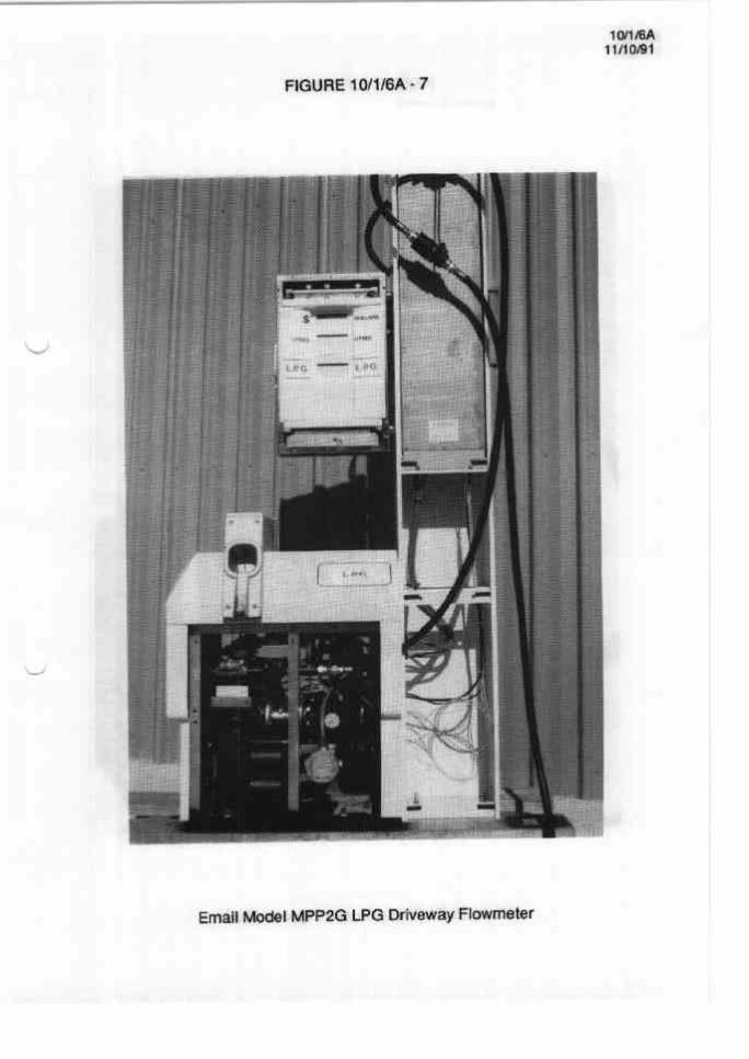
1.1 Variant 6
An Email model MPP2G dual LPG driveway flowmeter which uses the same hydraulic components as the model ELF2 (Variant 5). Instruments use Email model MPP indicators, Temperature conversion is achieved by means of an electronic compensator, whose electronics are located in the column that supports the indicator, along with the electronics for the vapour detection/elimination system of Variant 4.
The model MPP2G uses a multi-product style housing as shown in Figure 7.
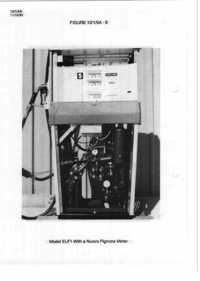
1.2 Variant 7
With a Nuovo Pignone model TLO 1254404 two-piston meter (Figure 8) replacing the Schwelm meter described for the pattern.
NOTIFICATION OF CHANGE
The following changes are made to Technical Schedule No 10/1/6A Variation No 1 dated 13/5/91;
(i) In cl. 1.1.2 Sealing, delete the reference to the vapour sensor interjunction box being sealed.
(ii) Delete the Test Procedure.
National Standards Commission
1 O/i/6A 4m93
TECHNICAL SCHEDULE No 10/1/6A
VARIATION No 3
Pattern: Email Model ELCl LPG Driveway Flowmeter.
Submittor: Email Electronics 88 - 94 Canterbury Road Kilsyth VIC 3137.
1. Description of Variant 8
An Email model 057-0291 liquid petroleum gas density measurement probe and interface unit for use only in conjunction with the Email vapour elimination/detection system (as described in Variant 4).
(i) The unit consists of a probe, a density interface and an interjunction unit. The probe includes 2 sensors, one each for density and vapour detection, and is fitted to the top of the vapour elimination chamber. The density sensor measures the relative permittivity (dielectric constant) of LPG flowing through the sensor and a signal is sent to the indicator to enable automatic temperature conversion to be carried out for the appropriate density.
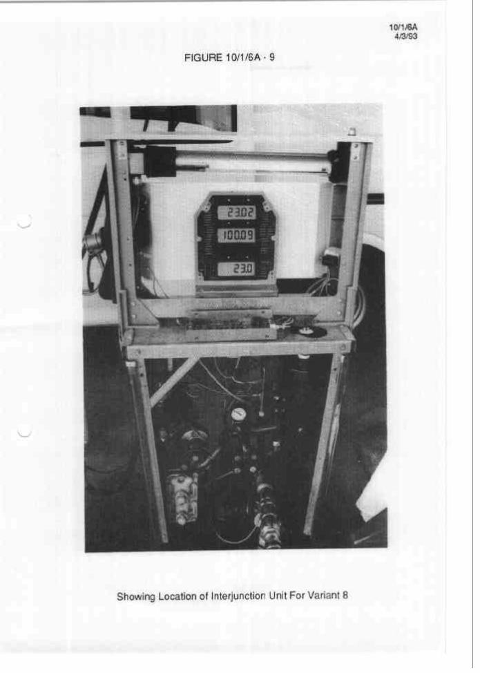
(ii) The interjunction unit is either located as shown in Figure 9 or, for model MPP2G (multi-product style housing - Variant 6) it is included in the column that supports the indicator.
(iii) If the vapour detection sensor detects vapour, a signal is provided to the computer to close the solenoid valve (refer Variant 4).
(iv) The temperature conversion included in the indicator has been programmed with the volume conversion equation for ASTM IP Table 54 for a density range between 0.500 and 0.555 kg/L.
(4 The indicator may display the current density and temperature of the product, and this is achieved by following the procedure as set out in Clause 1.1 (vi) of Technical Schedule 10/1/6A dated 21/l 2/88. The density is displayed on the top window of the indicator instead of the ‘cumulative dollars sold in whole dollars’.
Density @15 C Cum Tots Volume Temperature
“0.XxX” (in 0.001 increments) “Litres Sold” “Indirect Temp Reading”
. . ..I2

1 O/l f6A m/93
v T hnic I
Density displayed is the equivalent density @ 15OC, in the following range:
up to 0.499 low out of range reading 0.500 to 0.555 valid range 0.556 or greater high out of range reading
The display shows the density value without units, e.g. 0.515 not 0.515 kg/L.
(vi) If the temperature conversion is deactivated the density of the product is still displayed, but conversion will be based on a product temperature of 15OC.
TEST PROCEDURE - VARIATION No 1
Instruments should be tested in accordance with any tests included in the approval documentation for the indicator used, and in accordance with any relevant tests specified in the Inspector’s Handbook.
Maximum Permissible Errors at Verification/Certification
The maximum permissible errors applied during a verification test from normal flow rate to the minimum flow rate specified in the Certificate of Approval or Technical Schedule are:
fl .O% with the temperature convertor deactivated; and *1.2% with the temperature convertor activated.
1. Test of Vapour Detection/Elimination System
During a delivery, press the button adjacent to the temperature convertor ON/OFF switch. When this is held down, the vapour return solenoid will open and the vapour indicator LED, on the indicator or on the vapour sensor interjunction unit, will illuminate.
2. Test of Automatic Density Measuring Device
Check that the density displayed corresponds to the density of the product being measured (+0.005 kg/L). Refer to clause 1. (v).
3. Test of Temperature Conversion Facility
Check that the temperature displayed corresponds to the temperature of the product being measured (+0.5OC). Refer to clause 1. (v).

._
LPG Approvals 25m94
National Standards Commission
NOTIFICATION OF CHANGE
VARIOUS CERTIFICATES OF APPROVAL
The following changes are made to the approval documentation for various LPG _ flowmeter approvals as listed below:
In the approvals listed below, remove from the Certificate, Technical Schedule and Test Procedure, any Condition of Approval or clause that refers to instruments being verified, re-verified or calibrated at specific intervals. (Note that the re-verification period is determined by the Trade Measurement Authority in the State or Territory in which the instrument is located.)
APPROVAL NUMBER PATTERN
10/l/2 Halco Neptune 32/38 mm LPG Flowmeter
Pi o/1/3 lOlll3A PlO/l/5 P10/1/6 10/1/6A PlOll/7 1 O/l/8 1 Olll8A 10/l/9 PlO/l/lO lO/l/lOA 10/l/l 1 10/l/12 10/l/13
Acme Model LGD 100 LPG Driveway Flowmeter Acme Model LGD 10% LPG Driveway Flowmeter Batchen Model Mk II LPG Driveway Flowmeter Wayne Model ELCl LPG Driveway Flowmeter Email Model ELCl LPG Driveway Flowmeter lndeng Model MK0 LPG Driveway Flowmeter Gilbarco Model T093D LPG Driveway Flowmeter Gilbarco Model T093D LPG Driveway Flowmeter Batchen Model Commander LPG Driveway Flowmeter LPG Engineering Model Stargas LPG Driveway Flowmeter LPG Engineering Model Stargas LPG Driveway Flowmeter LPG Engineering Model Stargas EPSN LPG Driveway Flowmeter CleverHead Model 93 LPG Driveway Flowmeter Batchen Model SCB Commander LPG Driveway Flowmeter
PI Oi2!2 1012l3 P 1 O/2/4
Liquid Controls Model MA-7-GY-10 Bulk LPG Flowmeter Neptune Model 4D 32 mm Bulk LPG Flowmeter Euromatic Model FL 1112-125 Turbine Bulk LPG Flowmeter
Signed and sealed by a person authorised under Regulation 9 of the National Measurement (Patterns of Measuring Instruments) Regulations to exercise the powers and functions of the Commission under this Regulation.
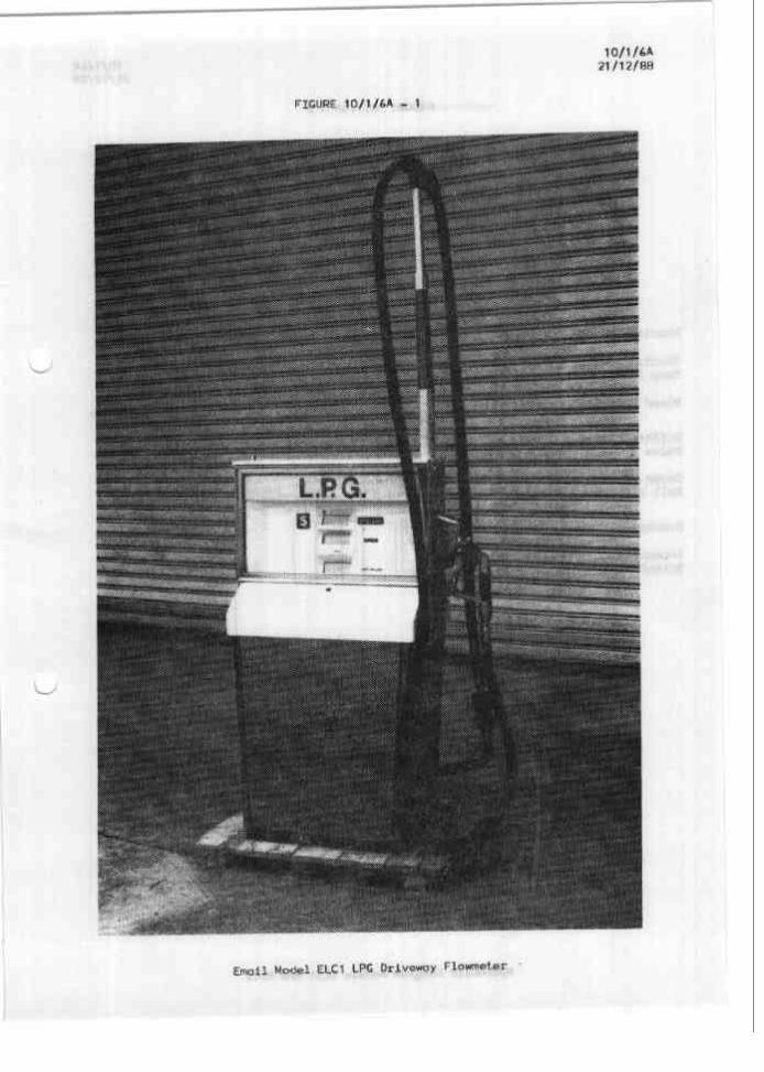
lO/l/bA 21/12/88
FIGURE lO/l/bA - 1
1 O/l /6A 21/12/08
FIGURE 10/1/6A - 2
Bleed Screw
Differential Valve
I
L Themeter Weli
-Gas Purger
- Sight Glass
'Valve Non- Return & Pressure * Relief
'Filter *
valve & 1.3/4 AaTe Maptor
LValves
Fran Supply Tad,
Hydraulic Diagram Models ELSl And ELCl

T
ST
‘HERMOM WELL
‘RAINER
lOlll6A 21 /12/w
FIGURE 10/1/6A - 3
GAS VENT
BLEED SCREW
PISTON VALVE
PI LOT VALVE
M -L l--YzmFLoAT
llQUlD IN1
NON RETU
7 \LlQlJlD OUTLET
.ET
RN
Neptune Gas Purger - Schematic Diagram
--- .---.--~-~----..
10/1/6A 21/12/88
FIGURE lOlll6A - 4
Piping Arrangement For Pressure Gouge Ad s.zding Of ~emperoture Compensation Switch Cover

FIGURE 10/1/6A - 5 10/1/6A 1315191
Email Model ELF1 LPG Driveway Flowmeter

10/1/6A 13/5/91
I--------- I I I 8
.,
.- -:
I
I c :
_-
i i I I I
i ; .I..,.. r I..-!
C
101lffiA 11/10/91
FIGURE lOHl6A - 7
Email Model MPPZG LPG Driveway Flowmeter
-.. ---
1 ON6A 11/10/91
FIGURE 10/1/6A - 8
Model ELF1 With a Nuovo Pignone Meter
10/1/6A 4m93
FIGURE 10/116A - 9
Showing Location of Interjunction Unit For Variant 8