national synchrotron light source ii rsi document no. … specifications and interfaces for the...
TRANSCRIPT

National Synchrotron Light Source II RSI Document No. 1.04.01.02
---------------------
Requirements, Specifications and Interfaces
for the Experimental Facilities Utilities
Andy Broadbent,
with help from Erik Johnson, Lino Miceli, Sushil Sharma, Ove Dyling, Nick Simos, Ron Beauman, and others.

NSLS-II EXPERIMENTAL FACILITIES UTILITIES RSI DOC. NO. 1.04.01.02
2
1 Contents 2 Overview ............................................................................................................................................................. 52 3 Introduction ......................................................................................................................................................... 52
3.1 Experimental Facilities Utilities: WBS Dictionary Definition ................................................................... 52 4 Experimental Facilities Utilities Requirements ................................................................................................... 62
4.1 General ........................................................................................................................................................ 62 4.2 Communication and data transfer ............................................................................................................... 72 4.3 Standard Requirements for Beamline Utility Services at the Point of Usage ............................................. 82 4.4 Requirements for Beamline Utility Service Interfaces. .............................................................................. 82 4.5 Experimental Facilities Utilities: Provision of Services on Building Beneficial Occupancy. .................. 102
5 Experimental Facilities Utilities Specifications ................................................................................................ 112 5.1 Electrical Systems ..................................................................................................................................... 112
5.1.1 Electrical Cable Trays above Walkway ................................................................................................ 122 5.1.2 Electrical Earthing Schemes ................................................................................................................. 122
5.2 Water Systems .......................................................................................................................................... 132 5.2.1 Facility DI Water Specifications ........................................................................................................... 132 5.2.2 Chilled Water Specifications ................................................................................................................ 142
5.3 Liquid Nitrogen supply ............................................................................................................................. 152 5.4 Gas supplies and gas extraction system .................................................................................................... 162
5.4.1 Compressed Nitrogen Gas .................................................................................................................... 162 5.4.2 Special gases ......................................................................................................................................... 172 5.4.3 Gas extraction system ........................................................................................................................... 172 5.4.4 Special / Hazardous gas extraction system ........................................................................................... 172 5.4.5 General ventilation system .................................................................................................................... 192
6 Experimental Facilities Utilities Interfaces ....................................................................................................... 202 6.1 Interfaces with the ASD ............................................................................................................................ 212 6.2 Interfaces with the CFD ............................................................................................................................ 232 6.3 Interfaces with ES&H ............................................................................................................................... 242
7 References ......................................................................................................................................................... 252 8 Appendix 1. Electrical Power Consumption Estimate. .................................................................................... 262 9 Appendix 3. De-Ionized (Process) Water Consumption Estimate. .................................................................. 272 10 Appendix 4. Chilled Water Consumption Estimate. .................................................................................... 282 11 Appendix 5. Liquid Nitrogen Consumption Estimate. ................................................................................ 292 12 Appendix 6. Gaseous Nitrogen and Compressed Air Consumption Estimate. ............................................ 302 13 Appendix 7. Temperature Sensors Background Information. ..................................................................... 302 14 Appendix 8. Oxygen Depletion Alarms Background Information. ............................................................. 302

NSLS-II EXPERIMENTAL FACILITIES UTILITIES RSI DOC. NO. 1.04.01.02
3
Identification
This document, NSLS-II Experimental Facilities Utilities Requirement Specification and Interface (RSI) is a part of
the documentation system, mapping to the NSLS-II project Work Breakdown Structure (WBS) and Cost Estimate
Database (CED).
It captures and summarizes all requirements and specifications for the WBS element 1.04.01.02, Experimental
Facilities Utilities and describes all its technical interfaces with other WBS elements.
Compiled by
Signature Date
Andy Broadbent, XFD Beamlines Manager
Approvals
Qun Shen, XFD Director
Reviewed by
Ove Dyling, CFD
Steve Hoey, ES&H
Erik Johnson, ASD
Tom Nehring, Electrical Engineering
John Gosman, CFD
Andrew Ackerman NSLS
Debbie Bauer, Environmental Compliance
Representative
Yong Cai, IXS BL Group Leader
Yong Chu, HXN BL Group Leader
Andrei Fluerasu, CHX BL Group Leader
Cecilia Sanchez-Hanke, CSX BL Group Leader
Juergen Thieme, SRX BL Group Leader
Eric Dooryhee, XPD BL Group Leader

NSLS-II EXPERIMENTAL FACILITIES UTILITIES RSI DOC. NO. 1.04.01.02
4
Document Updates
The NSLS-II Experimental Facilities Utilities RSI is a controlled document, revised under change control.
Revision number Date Authorized by Changes made;
Version 5 April 2nd 2008 Andy Broadbent Interface Committee Recommendations on 1st April 2008, including simplification of
interface descriptions, and putting data into table form.
Version 6 April 10th 2008 Andy Broadbent Interface positions better defined following discussions with Ove Dyling.
Version 7 April 22nd 2008 Andy Broadbent Improved electrical service description added.
Version 8 May 13th 2008 Andy Broadbent Addition of vibration criteria from Nick Simos.
Detailed review with Ove Dyling.
Addition of tepid water system for emergency showers.
Version 9 23rd May 2008 Andy Broadbent Removal of building and environmental specifications to a separate RSI document
Version 1.0 2nd July 2008 Andy Broadbent First version under change control.
Incorporation of changes suggested by Nick Gmür and John Hill
Version 2.0 8th Sept 2008 Andy Broadbent Incorporation of changes suggested by Andrew Ackerman.
Version 2.1 9th April 2009 Andy Broadbent LN2 connections – diameter implied by flow specifications, rather than specified
explicitly. Expansion of allowable pressure range.
Change of GN2 supply to compressed air (from within SR tunnel) and addition of LP
GN2 pipe with LN2 system.
Removal of the 60% coverage restriction for some of the utilities.
Version 2.2 3rd June 2009 Andy Broadbent Amendments to GN2 pressure and flow rates (Table 5, and Appendix 6) on the
advice of John Gosman.
Version 3 18th August
2010
Andy Broadbent Incorporation of comments from Nick Gmur, amendment to reviewers list.
Table 1 Revision Log
Acronyms and Abbreviations (***these need checking for completeness)
ASD Accelerator Systems Division
CED Cost Estimate Database
CFD Conventional Facilities Division
EPS Equipment Protection System
FO Fiber Optic
FOE First Optics Enclosure
IDF Intermediate distribution Frame
LOB Laboratory Office Building
OM3 A type of high quality multimode fiber optic cable
PPS Personnel Protection System
RSI Requirements, Specifications, Interfaces
SR Storage Ring
WBS Work Breakdown Structure
XFD Experimental Facilities Division
List of Tables
Table 1 Revision Log ................................................................................................................................................. 42 Table 2 Electrical Services Specifications ............................................................................................................... 112 Table 3 Water Services Specifications .................................................................................................................... 132 Table 4 Liquid Nitrogen Services Specifications .................................................................................................... 152 Table 5 Nitrogen Gas Specifications ....................................................................................................................... 162 Table 6 Gas Extraction System Specifications ........................................................................................................ 172 Table 7 Possible exhaust gases emitted from beamlines ......................................................................................... 182 Table 8 Interfaces of WBS element 1.04.01.02, XFD Utilities with the ASD (WBS 1.03) .................................... 212 Table 9 Interfaces of WBS element 1.04.01.02, XFD Utilities with the CFD (WBS 1.05) .................................... 232 Table 10 Interfaces of WBS element 1.04.01.02, XFD Utilities with ES&H (WBS 1.01.02) ................................ 242

NSLS-II EXPERIMENTAL FACILITIES UTILITIES RSI DOC. NO. 1.04.01.02
5
2 OVERVIEW
Section-3 has some introductory remarks. In Section-3.1, the WBS Dictionary entry of the Experimental Facilities
Utilities is given. Section 4 lists all environmental and utilities requirements. Section-5 summarizes all the
Experimental Facilities Utilities Specifications, by dividing them into four categories; Electrical, Water, Liquid
Nitrogen and Gas supply and exhaust system. Section-6 provides a list of its technical interfaces with the other parts
of the NSLS-II project and, finally, References are given in Section-7.
3 INTRODUCTION
This document describes a standard package of utilities for NSLS-II beamlines. Requirements and specifications of
individual beamlines may in part differ from this standard package to meet specific needs (e.g. higher power
consumption, or greater water flows). These additions are outside the scope of this document and will be defined in
the individual beamline RSI documents.
The document also defines the overall requirements for the beamlines within the facility and thus provides a
specification to the Conventional Facilities Division for the interface points (mainly on, or around, the SR tunnel
roof).
The installation of the Beamlines Utilities is a major activity for completion of the beamlines. In terms of
installation sequence, the Beamline Utilities follows the installation of the enclosures and only then can the
installation of the beamline optics and end station proceed. The installation of the Beamline Utilities is on the
critical path for installation of beamline equipment.
3.1 Experimental Facilities Utilities: WBS Dictionary Definition
Specification of the utilities needed for use by Experimental Facilities includes experimental floor exclusive of
those required for supporting beneficial occupancy of the space (HVAC, lighting, convenience power, etc.). Does
not include activities related to bringing these utilities from the facility drop off to the beamline.

NSLS-II EXPERIMENTAL FACILITIES UTILITIES RSI DOC. NO. 1.04.01.02
6
4 EXPERIMENTAL FACILITIES UTILITIES REQUIREMENTS
4.1 General
The Synchrotron Facility is designed to operate continuously 24 hours per day, 7 days per week (≥ 5,000 User
Beam Hours per year). The design life of the beamline utilities system shall be a minimum of 25 years.
The environmental conditions (temperature, temperature stability and humidity) are defined in the document
“Experimental Facilities Requirements, Specifications and Interfaces for the Ring Building and Experimental
Floor”, RSI Document No. 1.04.05.AB.
The utilities system shall be designed such that no personnel hazard or damage to any component within the
utilities system can result from any interruption to, or loss of, these services.
Work according to these requirements and specifications includes: detailed design, review and approval,
manufacture, installation, testing, commissioning, documentation, maintenance and coordination with the ES&H
division.
The following tasks are included in the Scope of Work for the Beamline Utilities:
a. Design, review and approval of the mechanical services distribution and electrical systems;
b. Production of the manufacturing, installation and as-built drawings as well as all procedural and
maintenance documents;
c. Supply of materials;
d. Manufacturing of custom parts;
e. Purchase of all parts;
f. Clean assembly of systems;
g. Inspection and testing;
h. Installation at the beamline, including building permits as required for the works;
i. Preventing damage to, and maintaining the integrity of, all enclosures (a.k.a. hutches, or experimental
stations);
j. Precise work coordination with the enclosures contractor;
k. Commissioning, testing and certification of the installation;
l. On-site training, for operation, maintenance and fault diagnosis.

NSLS-II EXPERIMENTAL FACILITIES UTILITIES RSI DOC. NO. 1.04.01.02
7
4.2 Communication and data transfer
Communications to the beamline hub shall be via fiber-optical cable from a local Intermediate Distribution Frame
(IDF) to the Beamline hub (normally on the roof of the beamline FOE).
The interface point to the XFD scope (and budget) will be at the IDF.
The FO cable from the IDF to the beamline router will comprise 12 individual fibers, and may be high
quality multimode (e.g. OM3) with a typical data rate of up to 10 Gb/sec per fiber.
The local hub will provide a 1 Gb/sec sub-network for the beamline control system from a 24 or 48 port
CISCO or equivalent router (the specification of this device can be decided later).
The FO connection shall provide access (as required) to other sub-networks (e.g. to request an insertion
device move from the accelerator network).
The FO connection shall provide (fiber optic) network access for User data storage at a local (shared)
RAID array (probably located in the LOB),
Access to the internet for staff and Users shall be accomplished via the FO connection to the beamline.
This external access to (and from) the internet may be used for remote control and monitoring of the
beamline or external (User) storage.
The communications system shall include provision for two phone outlets per beamline.

NSLS-II EXPERIMENTAL FACILITIES UTILITIES RSI DOC. NO. 1.04.01.02
8
4.3 Standard Requirements for Beamline Utility Services at the Point of Usage
The scope of supply for the standard utility services to all Beamlines is as follows;
a. Electrical power distribution from the interface points for both sensitive and non-sensitive power at the
ratchet wall including sub-panel distribution boards with appropriate and properly labeled circuit breakers
at each enclosure or experiment area, cable trays, all the electrical outlets in the enclosures and along the
beamline and wiring to light fixtures, fans, hoists, etc. inside the enclosures. It also includes electrical
power outlets in the hutch, cabin and user area;
b. Electrical grounding system from the interface point on the SR tunnel roof;
c. De-ionized (process) water distribution for beamline components needing cooling due to photon heatloads.
See Table 3 Water Services Specifications;
d. Chilled water distribution to all equipment racks and some items of end station equipment such as furnaces,
compressors, etc. See Table 3 Water Services Specifications;
e. Liquid nitrogen distribution from the local interface point on the SR tunnel roof;
f. Compressed nitrogen gas from the local interface point on the SR tunnel roof;
g. Facility compressed gas (compressed air);
h. Experimental gases distribution from gas cylinders into hutches;
i. Ambient temperature sensor installation inside enclosures (hutches);
j. Oxygen depletion sensor installation where required following calculations defined in the SBMS “ODH
Classification/Controls” subject area to determine the need and posting requirements. This may include
optics hutches with LN2 cooled monochromators and compressed nitrogen gas delivery systems, and all
experimental stations (unless it can be shown that there will NEVER be any chance that a cryogenic system
or compressed N2 gas will be used in the enclosure, in practice this is very difficult to do – an alternative
would be to engineer the hazard out of the system, eg with flow restrictions, fans etc), according to ES&H
requirements;
k. Communications, including: Beamline LAN with switches and racks (including Ethernet outlets in the
hutches, cabin or user area), and telephone lines (two per beamline);
l. Cabling and piping support structures, including necessary pylons and roof supports for cable trays, for all
utilities as well as EPS and PPS cables;
m. Gas-exhaust system for ventilating fume hoods, etc. from the User area or (less likely) from within
enclosures to a common exhaust manifold.
n. Air exchange system for forcing filtered experimental hall air into the hutch (this will then leak out via
labyrinths and custom air outlets). The fans are mounted on the hutch roofs and air passes in through a vent
labyrinth; the fans will be included in the hutch or cabin contracts and will be wired up under the beamlines
utilities work package. This work is entirely covered by XFD budgets.
o. Specialized hazardous gas exhaust (where this is required due to Health and Safety concerns that the gas
exhaust system is inadequate) would be a special utility request and needs to be coordinated with CFD and
ES&H division. This is outside the scope of this document. This system would probably be constructed in
polypropylene for chemical resistance and operation in the 32-150F (0-65C) temperature range.
p. Emergency lighting and painting of the floor may be required in the region of an emergency egress duck-
under. If required, this will come under the Beamline Utility Services work package.
q. Emergency showers and eyewash stations are required within unobstructed 50’ of positions where
corrosives are being handled. This is addressed within the document “Experimental Facilities
Requirements, Specifications and Interfaces for the Ring Building and Experimental Floor”, RSI Document
No. 1.04.05.AB
4.4 Requirements for Beamline Utility Service Interfaces.
The utility connections (or provision for their later easy addition) generally located on the SR tunnel roof are to be
included as part of the basic building design, and will be detailed by the Architect. The full requirements
specifications are provided later in this document.

NSLS-II EXPERIMENTAL FACILITIES UTILITIES RSI DOC. NO. 1.04.01.02
9
The scope of supply for the beamline utility service interfaces on the SR tunnel roof is as follows:
a. Electrical power interface points for sensitive and non-sensitive (“clean” and “dirty”) 120V and 208V 3-
phase electrical power including provision for up to four circuit breakers (in total), located within a load
panel on the inside building wall above the SR tunnel roof;
b. Electrical grounding system interface point;
c. De-ionized (process) water at interface (flow and return) points on the side of the SR ratchet shield wall at a
position roughly in the middle of a future FOE, and as close to the ceiling as possible. It is expected that
this will be approximately 20’ downstream from the beamline penetration of the ratchet wall and
approximately 4’ below the top of the ratchet wall, with isolation valves, if appropriate, within the SR
tunnel. The XFD scope of supply will include a second isolation valve inside the FOE;
d. Chilled water interface (flow and return) points expected to be on top of the SR tunnel fixed to a 6’ high
unistrut frame with appropriate quarter turn isolation valves and downward pointing connection points at a
height of approximately 5’;
e. Liquid nitrogen system interface point expected to be on the SR tunnel roof attached to the same unistrut
frame as the chilled water, and at the same height, with an appropriate cryogenic isolation valve and
connection bayonet;
f. Gaseous nitrogen interface point expected to be on the SR tunnel roof adjacent to the liquid nitrogen
interface point, with an appropriate gas isolation valve and connection fitting;
g. Facility compressed gas (compressed air), from within the SR tunnel with a quarter turn isolation valve, as
appropriate, passing through the SR ratchet shield wall immediately adjacent to the DI water pipes,
terminating at an interface point outside the SR tunnel;
h. Communications, interface point including:
i. Fiber optic cabling from the local IDF (Intermediate Distribution Frame), to the beamline interface
point either in the service building or at intermediate points between service buildings (total 10
interface points). Splicing of the FO cable is to be avoided. The XFD scope of supply, on each
beamline, will include running of FO cable around the inside building wall to a point close to the
beamline and then be routed over the walkway on top of the SR tunnel to the appropriate rack on
the beamline;
ii. Connection point on the unistrut interface panel (also used for chilled water and LN2) for two
telephone lines per beamline (these lines will be run in copper cable from the nearest Service
Building);
iii. The specifications for the FO cables are included in the Communications RSI.
i. Gas-exhaust system manifold designed to meet the requirements outlined in Table 7 Gas Extraction
System Specifications.
j. Provision shall be made in the utilities piping supports for the later addition of a 6” diameter metal or
plastic Helium gas recovery pipe. This shall go around the facility above the SR tunnel roof, and provision
shall be made later for;
a. connection to a helium gas bag (probably to be located below the building roof, suspended
between bar joists),
b. a compressor in a separate small building, and
c. trailer parking for the compressed gas bottles.
The CFD scope is no more than provision of brackets and space, for the recovery pipe on the pipe support.
k. A flow and return “stub” for connection to the fire sprinkler system shall be provided adjacent to the
beamlines, above the SR tunnel roof. See the document “Experimental Facilities Requirements,
Specifications and Interfaces for the Ring Building and Experimental Floor”, RSI Document No.
1.04.05.AB.
l. A tepid water system shall be provided around the facility on the inside of the outer wall adjacent to the
access corridor to allow for emergency shower stations to be added as required. See the document
“Experimental Facilities Requirements, Specifications and Interfaces for the Ring Building and
Experimental Floor”, RSI Document No. 1.04.05.AB.

NSLS-II EXPERIMENTAL FACILITIES UTILITIES RSI DOC. NO. 1.04.01.02
10
4.5 Experimental Facilities Utilities: Provision of Services on Building Beneficial Occupancy.
The following services will be provided around the facility at the time of beneficial occupancy of the building:
1. Electrical power cables;
2. Electrical grounding system;
3. De-ionized (process) water with holes in the SR tunnel ratchet wall, and interface points;
4. Chilled water;
5. Facility compressed gases (Compressed air and N2 gas);
6. Tepid water loop around the walkway for the later addition of eyewash/shower stations around building
periphery and at beamlines as the facility gets built out.
7. Liquid nitrogen system;
8. Non-hazardous gas-exhaust system.
The following services will be installed to specific beamline locations, as needed:
9. Fiber optic cabling;
10. Telephone connections;
11. Beamline transformers and load panels.
NSLS-II EXPERIMENTAL FACILITIES UTILITIES RSI DOC. NO. 1.04.01.02
11
5 EXPERIMENTAL FACILITIES UTILITIES SPECIFICATIONS
5.1 Electrical Systems
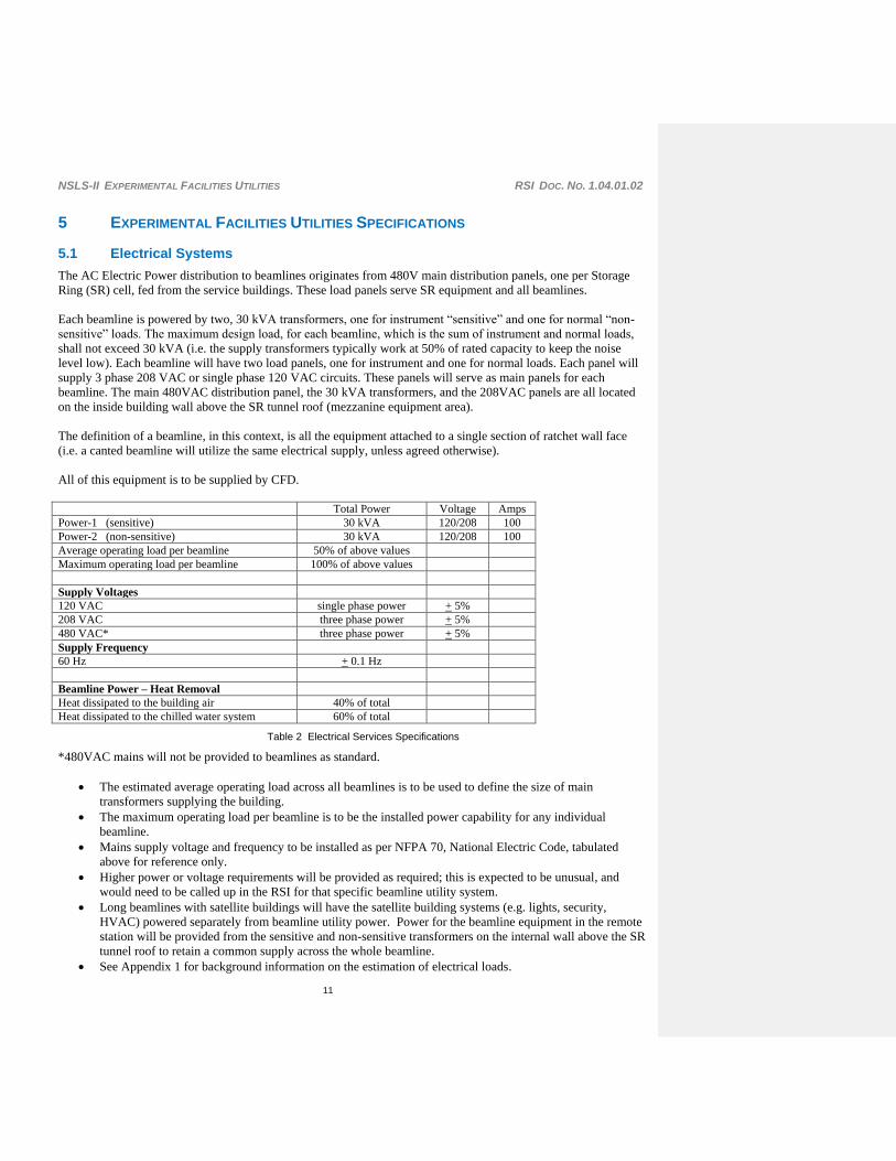
The AC Electric Power distribution to beamlines originates from 480V main distribution panels, one per Storage
Ring (SR) cell, fed from the service buildings. These load panels serve SR equipment and all beamlines.
Each beamline is powered by two, 30 kVA transformers, one for instrument “sensitive” and one for normal “non-
sensitive” loads. The maximum design load, for each beamline, which is the sum of instrument and normal loads,
shall not exceed 30 kVA (i.e. the supply transformers typically work at 50% of rated capacity to keep the noise
level low). Each beamline will have two load panels, one for instrument and one for normal loads. Each panel will
supply 3 phase 208 VAC or single phase 120 VAC circuits. These panels will serve as main panels for each
beamline. The main 480VAC distribution panel, the 30 kVA transformers, and the 208VAC panels are all located
on the inside building wall above the SR tunnel roof (mezzanine equipment area).
The definition of a beamline, in this context, is all the equipment attached to a single section of ratchet wall face
(i.e. a canted beamline will utilize the same electrical supply, unless agreed otherwise).
All of this equipment is to be supplied by CFD.
Total Power Voltage Amps
Power-1 (sensitive) 30 kVA 120/208 100
Power-2 (non-sensitive) 30 kVA 120/208 100
Average operating load per beamline 50% of above values
Maximum operating load per beamline 100% of above values
Supply Voltages
120 VAC single phase power + 5%
208 VAC three phase power + 5%
480 VAC* three phase power + 5%
Supply Frequency
60 Hz + 0.1 Hz
Beamline Power – Heat Removal
Heat dissipated to the building air 40% of total
Heat dissipated to the chilled water system 60% of total
Table 2 Electrical Services Specifications
*480VAC mains will not be provided to beamlines as standard.
The estimated average operating load across all beamlines is to be used to define the size of main
transformers supplying the building.
The maximum operating load per beamline is to be the installed power capability for any individual
beamline.
Mains supply voltage and frequency to be installed as per NFPA 70, National Electric Code, tabulated
above for reference only.
Higher power or voltage requirements will be provided as required; this is expected to be unusual, and
would need to be called up in the RSI for that specific beamline utility system.
Long beamlines with satellite buildings will have the satellite building systems (e.g. lights, security,
HVAC) powered separately from beamline utility power. Power for the beamline equipment in the remote
station will be provided from the sensitive and non-sensitive transformers on the internal wall above the SR
tunnel roof to retain a common supply across the whole beamline.
See Appendix 1 for background information on the estimation of electrical loads.

NSLS-II EXPERIMENTAL FACILITIES UTILITIES RSI DOC. NO. 1.04.01.02
12
Emergency generators are reserved for equipment that would have Life Safety consequences if power is
lost. It should be noted that no beamline equipment has been identified in this category. Note that it is
likely that cold rooms or freezers in the LOBs will require a UPS, these are outside the scope of this
document but will be considered on a case by case basis and be financed from the LOB fitout budget.
Uninterruptible Power Supplies will be installed in beamline racks on an “as needed” basis. These will be
used to provide power continuity to critical servers etc, and are included in the beamline control system
costs (i.e. XFD budget) and not the utilities distribution.
Cryocoolers used for keeping monochromator crystals at liquid nitrogen temperature may be fitted with a
dedicated UPS (typical single phase power consumption of a cryocooler is 750W), when the cost and risk
of unit power failure warrants expenditure on such a system.
Any UPS used shall be sized appropriately for the load and the risk / duration of power outages.
Electrical power distribution design shall meet all relevant codes and standards (e.g. NEC, OSHA, DOE
Code 10 CFR 851 and BNL site regulations).
Typically a beamline may have single phase mains outlets at 1m intervals along the internal in-board side
of the hutch. External mains sockets will at least double this number; in total this could amount to 80
sockets for clean and dirty power combined.
5.1.1 Electrical Cable Trays above Walkway
Two cable trays will be provided around the building exterior wall at a height of >4m, above the walkway, at about
300mm spacing, vertically. This is to be used wherever a convenient run from a beamline to an LOB is on the
outside diameter of the building, rather than via the SR tunnel roof.
Cable trays are required for:
One for communications, ethernet, fiber-optics, and other low level signals (including fire alarm cabling - if
this is permitted),
One for noisy signals and/or voltages (≥50 volts including mains).
5.1.2 Electrical Earthing Schemes
5.1.2.1 Facility Protective Earth Scheme
The protective earth system for the facility is wired by pentant back to the main earth in each service building as
part of the mains supply conductors. This conductor will be connected to the centre-taps of the secondaries of
individual beamline transformers and then distributed radially to the beamlines from this point. This earth is not
intended to be a current carrying conductor (except during a fault).
5.1.2.2 Beamline Protective Earth Scheme
The beamline earth will be distributed to the beamline equipment via the main supply conductors from the
transformers, via the local breaker panel. Sensitive and non-sensitive earths will be separated and only interconnect
as the transformers link to the main building earthing system. Switched mode and variable speed type devices shall
be connected to the non-sensitive earth as part of this cable.
Sharing of equipment across beamlines is discouraged, and very great care needs to be taken. This requires an
Electrical Engineer to advise/design.
All beamline equipment shall be connected to earth in accordance with electrical codes.
NSLS-II EXPERIMENTAL FACILITIES UTILITIES RSI DOC. NO. 1.04.01.02
13
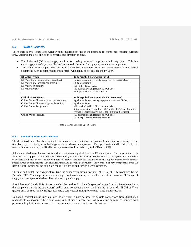
5.2 Water Systems
There shall be two closed loop water systems available for use at the beamline for component cooling purposes
only. All lines must be labeled as to contents and direction of flow.
The de-ionized (DI) water supply shall be for cooling beamline components including optics. This is a
clean supply, carefully controlled and monitored, also used for supplying accelerator components.
The chilled water supply shall be used for cooling electronics racks and other pieces of non-critical
equipment, such as compressors and furnaces which may be brought on-site by Users.
DI Water System (to be supplied from within the SR)
DI Water Flow (maximum per beamline) 15 gallons/minute (velocity in pipe not to exceed 6ft/sec)
DI Water Flow (average per beamline) 12 gallons/minute
DI Water Temperature 85F+0.2F (29.5C+0.1C)
DI Water Pressure 150 psi max design pressure at 100F and
~100 psi typical working pressure
Chilled Water System (to be supplied from above the SR tunnel roof)
Chilled Water Flow (maximum per beamline) 6 gallons/minute (velocity in pipe not to exceed 6ft/sec).
Chilled Water Flow (average per beamline) 3 gallons/minute.
Chilled Water Temperature 53F nominal, with ~20F temperature rise
(this assumes the removal of ~60% of the 30 kVA per beamline
average electrical load with a 6 gallon/minute flow rate).
Chilled Water Pressure 150 psi max design pressure at 100F and
100-120 psi typical working pressure
Table 3 Water Services Specifications
5.2.1 Facility DI Water Specifications
The de-ionized water shall be supplied to the beamlines for cooling of components (seeing a power loading from x-
ray photons), from the system that supplies the accelerator components. The specification shall be driven by the
needs of the accelerator (specifically the requirement for low resistivity (~1 MΩ-cm +5%)).
All water cooled beamline components shall have water supplied from the DI water system for the accelerator via
flow and return pipes run through the ratchet wall (through a labyrinth) into the FOEs. This system will include a
water filtration unit at the service building to ensure that any contamination in the supply cannot block narrow
passageways in components. The filtration unit shall prevent performance deterioration of any components over the
lifetime of the beamline, including bio-fouling, oxidation and foreign body obstruction.
The inlet and outlet water temperatures (and the conductivity from a facility EPICS PV) shall be monitored by the
Beamline EPS. The temperature sensors and generation of these signals shall be part of the beamline EPS scope of
supply and is not part of the beamline utilities scope of supply.
A stainless steel (grade 304) pipe system shall be used to distribute DI (process) water from the interface point to
the components inside the enclosure(s) and/or other components down the beamline as required. EPDM or Viton
gaskets shall be used for any flange seals where compression fittings or welded joints are impractical.
Radiation resistant plastic such as Poly-Flo or Nylon12 may be used for flexible connections from distribution
manifolds to components where bent stainless steel tube is impractical. All plastic tubing must be stamped with
pressure rating that meets or exceeds the maximum pressure available from the system.
NSLS-II EXPERIMENTAL FACILITIES UTILITIES RSI DOC. NO. 1.04.01.02
14
Tubing shall be used in conjunction with stainless steel instrumentation type compression ferrule fittings (e.g.
Swagelok or equivalent). Compression fittings interfacing with copper shall utilize appropriate metal to metal
connections such as parallel threaded o-ring connections. Flexible connections shall be kept to a minimum length.
The maximum flow velocity in any water circuit should be less than 2 m/s (for ambient noise minimization).
Output flow meters of very high reliability shall be provided on all process water circuits (e.g. of the Yokogawa or
the KOBOLD RCD-C, or equivalent, type). Valves shall also be included to isolate any parallel process water
circuits. The use of Teflon anywhere is prohibited.
A means to vent air and drain the process water distribution system shall be provided.
Facility to eliminate water hammer or other vibrations shall be provided, if required, in operation.
The beamline EPS shall include a means to detect a fault in the process water circuit (i.e. return flow stops; loss of
water volume due to leak or user usage) and to isolate the water system with an electrically operated valve in the
event of such a leak.
5.2.2 Chilled Water Specifications
The chilled water shall be used for the cooling of equipment racks.
This system shall be plumbed in rigid stainless steel (grade 304); with stainless steel braided flexible hoses only
where needed (e.g. racks needing to move). Fittings shall be Swagelok type.
If required, due to condensation, or risk of condensation, these lines shall be insulated and/or some temperature
control may be required.
NSLS-II EXPERIMENTAL FACILITIES UTILITIES RSI DOC. NO. 1.04.01.02
15
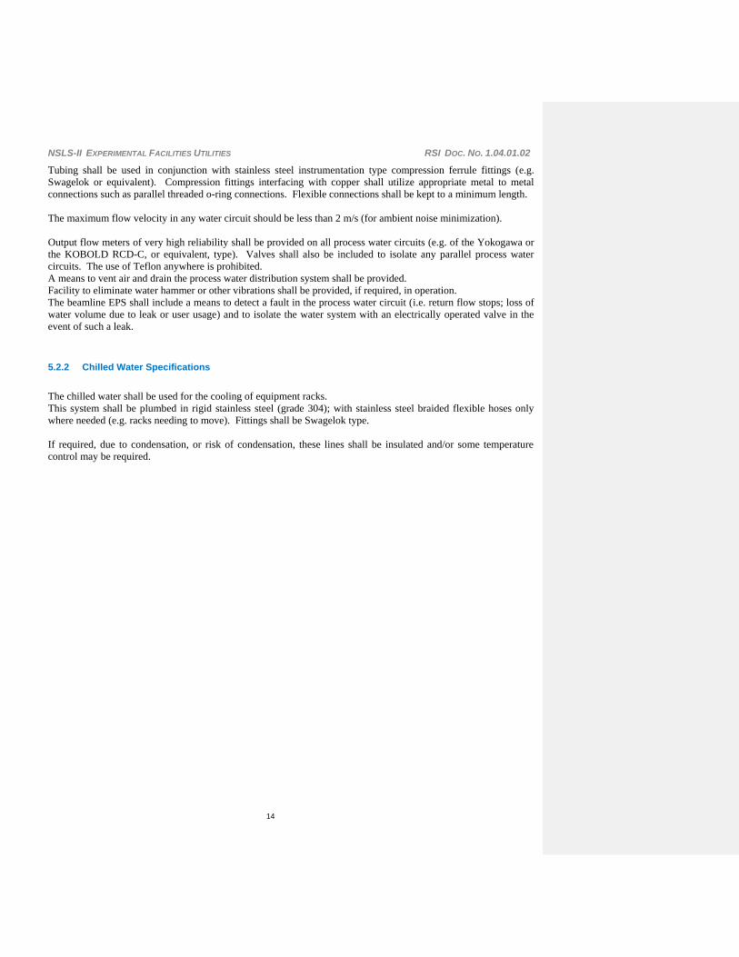
5.3 Liquid Nitrogen supply
The liquid nitrogen distribution system takes the liquid nitrogen from one or two storage tanks outside the facility
and pipes this to tap-off points adjacent to each of the Insertion Device beamlines (i.e. 30 tap-off points in total).
All lines must be labeled for contents and direction of flow.
This system shall also provide the liquid nitrogen required for the RF system. Background information on the flow
rates, etc. is provided in the Appendix (Section 11).
Average usage Supply Pressure Flow rate
23,000 Gallons / year / beamline
(87,000 l/yr)
This is equivalent to 600l/hr.
Within the range
2.0–3.0 Bar (30–45 psi)
40 Gallons/hr
(150 l/hr) minimum at each beamline
with 50% of spigots open
Table 4 Liquid Nitrogen Services Specifications
The interface points are expected to be ~1” nominal diameter bayonet fittings (male on the supply side, and
fitted with insulating, sealing covers), unless this is incompatible with the flow specifications above.
Mating fittings shall be provided by the system supplier.
All interface points shall be equipped with a cryogenic compatible isolation valve.
The supply pipe work shall be appropriately gas vented (and not rely on the beamline connections for gas
venting).
Flow restriction for ODH control, as appropriate.
Pressure reliefs venting into the experimental hall shall be located in all sections of pipe that can be isolated
and specified for a pressure commensurate with the design pressure of the system.

NSLS-II EXPERIMENTAL FACILITIES UTILITIES RSI DOC. NO. 1.04.01.02
16
5.4 Gas supplies and gas extraction system
5.4.1 Compressed Nitrogen Gas
Compressed Nitrogen shall be supplied to all beamlines in accordance with values in the Table 6
Compressed Air Specifications, below.
All lines to be labeled for contents and direction of flow.
The supplied compressed nitrogen gas shall be at room temperature.
The compressed nitrogen gas pipework shall follow the routing of the LN2 distribution system, taking gas
from the LN2 storage vessels, through an external heat exchanger (to bring the gas to room temperature)
and then routed around the facility high about the SR tunnel. This piping shall be in 1” pipework, unless
this is incompatible with the pressure and flow specifications below.
Drops shall be provided from the nitrogen gas “ring main” to the top of the SR tunnel, adjacent to the ID
beamline positions (30 in total). These drops shall be in ½” pipework, unless this is incompatible with the
flow specifications below.
The interface connection shall be on the top of the SR tunnel ratchet wall immediately adjacent to the LN2
interface point.
The interface is expected to be a standard ½” Male NPT fitting (with isolating valve). This is within the
CFD scope of supply.
Distribution from the interface point to the User connections within hutches, or elsewhere along the
beamline, is expected to be ½” tube, unless a larger diameter is required. Take-off points shall be Female
Nitto Hicupla ½” quick connect fittings. There will be four take-off points as standard, with locations to be
confirmed. This is all within the XFD scope of supply.
Supply requirement to each beamline Supply Pressure
Overall maximum system flow rate 20cfm (10 l/s) at STP.
Approximately 0.6 cfm at each of 15 interface points with all valves open.
30 psi (0.2 MPa) nominal with a maximum
system pressure of 125psi (0.85 MPa).
Table 5 Compressed Nitrogen Gas Specifications
5.4.2 Compressed Air
Compressed air shall be supplied to all beamlines in accordance with values in the Table 6 Compressed
Air Specifications, below.
The supplied compressed air shall be at room temperature.
The interface connection on the side of the SR tunnel ratchet wall is expected to be a standard ½” Male
NPT fitting (with isolating valve within the SR tunnel). This is within the CFD scope of supply.
Distribution from the interface point to the User connections within hutches, or elsewhere along the
beamline, is expected to be ½” tube, unless a larger diameter is required. Take-off points shall be Female
Nitto Hicupla ½” quick connect fittings. There will be four take-off points as standard, with locations to be
confirmed. This is all within the XFD scope of supply.
Supply requirement to each beamline Supply Pressure
0.4 cfm 0.22l/s) at STP average flow across all beamlines,
2 cfm (1 l/s) at STP maximum average flow, and
10cfm (5 l/s) at STP for 5 seconds intervals with 30 second recuperation
75 psi (0.5 MPa) nominal with a maximum
pressure of 125psi (0.85 MPa).
Table 6 Compressed Air Specifications

NSLS-II EXPERIMENTAL FACILITIES UTILITIES RSI DOC. NO. 1.04.01.02
17
5.4.3 Special gases
Special gases, (e.g. for XAFS ion chambers and soft X-ray experiments) will normally be provided from
local gas cylinders adjacent to the hutch.
These gases are NOT part of the standard utilities pack, and are provided only on special request (defined
within the individual Beamline RSI document).
Generally it is anticipated that 6mm stainless steel Swagelok fittings will be used.
5.4.4 Gas extraction system
An exhaust gas system shall be provided around the facility with one interface point available for each
beamline. The system shall maintain a negative pressure within the exhaust gas piping by means of
remotely located pumps or fans;
The system shall remove the exhaust gas from any given beamline at the flow rates defined in Table 7 Gas
Extraction System Specifications, below;
The exhaust duct shall be capable of withstanding an operating temperature range defined in Table 7 Gas
Extraction System Specifications;
Each termination point shall include a removable cap that seals the inlet when not in use, and to which a
Phoenix valve and/or HEPA filter may be easily attached.
Piping from this termination point to the extraction point (e.g. via fixed piping to an extraction port on the
equipment, or via an “elephant trunk” (either inside the hutch, via a labyrinth, or external to the hutch) will
be part of the Beamline scope.
The connection points shall be positioned above the access corridor around the facility, at an approximate
height of 22’ (~7m).
Temperature range for extracted gases 32F – 150F (0C to 65C) Extraction flow rate requirement at any given beamline 750 cfm at 73F (23C) Extraction flow rate requirement with all inlets open 400 cfm at 73F (23C)
Table 7 Gas Extraction System Specifications
5.4.5 Special / Hazardous gas extraction system
This extraction system is to be supplied as part of the CFD scope of supply, however the connections to beamlines
are not part of the standard utilities pack, and are provided only on special request (defined within the individual
Beamline RSI document), and after careful review with the relevant ES&H staff.
The system shall be “explosion proof” and shall be designed to meet all Legislative Requirements when venting
these gases into the atmosphere.
The exhaust gas extraction system will not be used to extract any radioactive or bio-hazardous materials.
An anticipated list of possible exhaust gases, by beamline, is provided below for information only. Please note that
some of these gases may require sensors and perhaps alarms under certain circumstances – ammonia is an example.
XAFS PD Nanoprobe IXS CHX/SAXS Soft x-ray PX IR
Gas
Hydrogen (H2) X X
Water (H2O) X
Helium (He) X X X X
Carbon Monoxide (CO) X X X X
Carbon Dioxide (CO2) X X X X
Nitrogen (N2) X X X X X X X X
Ammonia (NH3) X

NSLS-II EXPERIMENTAL FACILITIES UTILITIES RSI DOC. NO. 1.04.01.02
18
Argon (Ar) X X X X
Neon (Ne) X
Ethylene oxide X
Difluoroethane X
Chlorodifluoromethane X
Methanol vapor X X X X
Ethanol vapor X X X X
Acetone vapor X X X X
Chloroform vapor X
Ethylene imine (azridine) X
Freon 12 (dichlorodifluoromethane) X
Polyester X
Epoxy X
Sulfur based chemicals
Hydrogen Sulfide X
Organic liquids
Alcohols X
Ketones X
Aldehydes X
Esters X
Oil filled rotary pump fumes X X
Sulfur vapors from pumps X
Table 8 Possible exhaust gases emitted from beamlines

NSLS-II EXPERIMENTAL FACILITIES UTILITIES RSI DOC. NO. 1.04.01.02
19
5.4.6 General ventilation system
Ventilation of the individual hutches and cabins is required; this will not be part of the CFD responsibilities.
Fans with integral, replaceable, filter elements shall be fitted to the roof of each enclosure.
The fans will force filtered air into the hutch, which will then exit the hutch through various labyrinths
including a dedicated air outlet.
All such fans will be included in the relevant hutch or cabin contract.
The fan shall be able to move air through each enclosure at a rate of at least 6 m3/min. One dedicated air
inlet labyrinth (on the roof) and one dedicated air outlet labyrinth (on the wall, close to the floor) shall be
provided, per hutch, and sized to permit this air flow.
Each fan shall be equipped with variable speed control permitting continuous adjustment from 0% (off) to
100%. Adjustment will be possible only by beamline staff, typically to reduce noise and/or resonances
within the enclosure.
Electrical connection to the mains will be done within the beamline utilities work package.
Care shall be taken to ensure that the vibration criteria are met with the fan running. The vibration criteria
are addressed in the document “Experimental Facilities Requirements, Specifications and Interfaces for the
Ring Building and Experimental Floor”.

NSLS-II EXPERIMENTAL FACILITIES UTILITIES RSI DOC. NO. 1.04.01.02
20
6 EXPERIMENTAL FACILITIES UTILITIES INTERFACES
Tables No. 8, 9 and 10, list the interfaces with other WBS elements of the NSLS-II project, except for the
pre-Operations phase (WBS 1.06), which will be considered later. A first order justification for each
interface is given here where necessary, i.e. when it is not obvious from the attached WBS dictionary
definition. The interfaces identified here are defined and managed through meetings, software tools and
interface control documents.

NSLS-II EXPERIMENTAL FACILITIES UTILITIES RSI DOC. NO. 1.04.01.02
21
6.1 Interfaces with the ASD
Table 9 Interfaces of WBS element 1.04.01.02, XFD Utilities with the ASD (WBS 1.03)
WBS Title Dictionary Definition
1.03.04.08.02
Storage Ring
Electrical
Utilities
Design, specify, and procure storage ring electrical utilities. This
includes equipment enclosures, cable tray, AC power connections,
and special AC power. See the level-6 WBS entry for more
detailed descriptions. The procurement for electric utilities will
almost be standard commercial products. The racks will have some
simple factory modifications to minimize our labor costs. All
procurements will be done through a request for proposal buy.
This is so the project gets the exact technical specification and
delivery schedules needed, even through the components are
standard products
Reason: Although the electrical utilities are provided by CFD,
ASD provides design and specifications for the transformers and
load panels powering all beamline equipments. See also all WBS
elements at a lower level
1.03.04.08.03
Storage Ring
Mechanical
Utilities
Design, procure, and fabricate the mechanical utilities (process
water and compressed gas) associated with the storage ring. This
will include five process water pumping systems for each
Mechanical Equipment Room (MER) and one pumping system for
the storage ring RF system. There will be nitrogen gas
compressors also located in the MER to supply compressed gas for
various process valve operation (see the level-6 WBS entries,
below, for additional details).
Reason: ASD provides the process DI water system and
compressed N2-gas for the Experimental Facilities. Other, WBS
elements below 1.03.04.08.03, that specifically address DI water
and G-N2 must also be considered n developing this interface.
1.03.04.09.01
Storage Ring
Installation &
Test of
Mechanical
Utilities
Install and test all mechanical and electrical components
associated with the Storage Ring Water System and Storage Ring
Compressed Gas System. This includes all piping, heat
exchangers, pumps, and valves for each of the five Mechanical
Equipment Rooms (MERs), the distribution system associated
with each MER, and the connections to all specific components,
excluding the Injection System (which is under a separate WBS,
1.3.3.5.1). Labor will consist of both engineering and technical
staff.
This interface naturally follows from the above-identified interface
with 1.03.04.08.02.
1.03.04.09.02
Storage Ring
Installation of
Electrical
Install storage ring electrical utilities, which include all equipment
enclosures, cable trays, AC power connections, and special AC
power. Also includes the manpower to pull all subsystem cables

NSLS-II EXPERIMENTAL FACILITIES UTILITIES RSI DOC. NO. 1.04.01.02
22
Utilities for the entire storage ring. (Each subsystem is responsible to
terminate its own cables.) This WBS entry is mostly for
installation labor.
This interface naturally follows from the above-identified interface
with 1.03.04.08.03.

NSLS-II EXPERIMENTAL FACILITIES UTILITIES RSI DOC. NO. 1.04.01.02
23
6.2 Interfaces with the CFD
Table 10 Interfaces of WBS element 1.04.01.02, XFD Utilities with the CFD (WBS 1.05)
WBS Title Dictionary Definition
1.05.02
Conventional
Facilities
Engineering and
Design (Marty
Fallier)
Execution of engineering and design of NSLS-II buildings,
utilities, and improvements to land by developing design
requirements, preparing design drawings and specifications for
construction contracts, and providing engineering support during
the construction phase, to assure proper execution of the design
and complete as-built documentation.
Reason: beamline-utilities interfaces need to be considered as early
as possible, during the building design phase. This interface
extends to all WBS elements branching from this, namely the
Title-I and Title-II design activities until the final design is reached
and approved.
1.05.03.06 Ring Building
The building is divided into five pentants with a service building
within each pentant, and is connected to each of the other
buildings identified in separate WBS entries. The Ring Building
spaces include the accelerator tunnel, power supply and utility
service gallery on top of the storage ring tunnel, experimental floor
beamline areas, and service buildings totaling ~294,000 GSF.
Included are the building enclosure, all building finishes, and
distribution of services for the experimental and accelerator areas
within the building. Initial beamline utility services will be
distributed to pentants 1 and 5 and partially in pentants 2 and 4.
The Ring Building is the functional center of the facility and is the
primary element of the Ring Building contract.
Reason: beamline utilities services distribution. This interface
extends to all sub-activities branching from this WBS element,
namely 1.05.03.06.01 through 1.05.03.06.05, referring to the five
pentants in which the ring building is subdivided.
1.05.06.01
Ring Building
Commissioning
(Stephen Sawch)
This activity provides inspection, testing, O&M training, and start-
up commissioning services for the Ring Building HVAC systems
and services, including the Service buildings.
Reason: utilities commissioning phase. This will just verify that
the systems are installed in accordance with the construction
drawings and specifications. The beamlines will be installed much
later - several years after the ring bldg construction is done -
commissioning and calibration at this time must be done in concert
with operational staff because the contractor will be gone from the
site. It is also something that is best done with operating staff
given the imprecise nature of what is required and when.

NSLS-II EXPERIMENTAL FACILITIES UTILITIES RSI DOC. NO. 1.04.01.02
24
6.3 Interfaces with ES&H
Table 11 Interfaces of WBS element 1.04.01.02, XFD Utilities with ES&H (WBS 1.01.02)
1.01.02.01 ESH
Management
This function provides ESH management for safety & training
related activities associated with the NSLS-II R&D program,
the NSLS-II construction program, and the NSLS-II
commissioning activities. It specifically includes: 1.
Preparation of ESH manuals, procedures, etc. 2. Providing
support and guidance to NSLS-II staff regarding ESH and
training requirements 3. Conducting safety evaluations of
design to ensure compliance with DOE and BNL ESH
requirements 4. Monitoring workplace activities and conditions
to ensure compliance w/ DOE & BNL ESH. Determination of
ESH related training requirements, tracking training
compliance, and provision of NSLS-II ESH training for staff
members. 6. Preparation of safety assessment documents
needed to support CD-1, 2, 3, 4a, & 4b. 7. Coordination and
follow up of required ESH reviews associated with beneficial
occupancy and Accelerator Readiness Reviews.
The installation of beamline utilities raises safety issues:
electrical, high-pressure gases, etc. Compliance to safety
regulation requires coordination w/ ESS&H.
1.01.02.02 Shielding
Analysis
This WBS activity provides radiological support for NSLS-II
design and commissioning activities. It includes: 1. the
preparation of shielding analyses for the accelerator enclosures
and beamlines 2. Specification of required shielding 3. review
of design for radiological shielding to determine compliance
with BNL requirements. 4. Support and monitor commissioning
activities, including evaluations of shielding and radiation fields
generated during commissioning studies, evaluation of dose to
equipment and components as a result of operational beam
losses and evaluation of induced activity in machine
components to determine handling and storage requirements.
The installation of beamline utilities requires drilling into the
enclosures shielding walls. Radiation protection issues [1, 2].

NSLS-II EXPERIMENTAL FACILITIES UTILITIES RSI DOC. NO. 1.04.01.02
25
6.4
7 REFERENCES
1
Shielding estimates for First Optics Enclosures, Monochromatic Stations and Monochromatic Beam
Transports for the NSLSII Beamlines, NSLS-II Technical note
http://groups.nsls2.bnl.gov/eshqa/Shared%20Documents/Forms/AllItems.aspx?FolderCTID=&RootFolder
=%2feshqa%2fShared%20Documents%2fNSLS%20II%20Beamline%20Shielding%20Guidelines&SortF
ield=Modified&SortDir=Asc&View=%7bDCEBD175%2d88FE%2d4F8A%2dBE9A%2dF741DA69C56
E%7d
2 Beam line-Utilities Interface System Development:
http://groups.nsls2.bnl.gov/ExperimentalFacilities/XFD_Interface_Systems_Development/Beaml
ine_Utilities_Interface_System/default.aspx
3 Standard Beam line-Utilities Interface Control Document:
http://groups.nsls2.bnl.gov/ExperimentalFacilities/DocumentReferenceLibrary/InterfaceControlD
ocuments/Forms/AllItems.aspx?RootFolder=%2fExperimentalFacilities%2fDocumentReference
Library%2fInterfaceControlDocuments%2fXFD%20Utilities%20Interface%20System&FolderC
TID=&View=%7bBECC950B%2dE59D%2d4823%2dBEB6%2dAE7205985858%7d
Field Code Changed
Field Code Changed
Field Code Changed

NSLS-II EXPERIMENTAL FACILITIES UTILITIES RSI DOC. NO. 1.04.01.02
26
8 APPENDIX 1. ELECTRICAL POWER CONSUMPTION ESTIMATE.
Comments from Oxford Danfysik
To answer your question in the absence of anything else please find my rule of thumb measures:-
Mains power is complex and depends upon the components.
I would budget 50W/stepper axis plus 100W per large component - Mirror or DCM. The sizing of the circuit breakers should reflect this.
The sizing for the air-conditioning should be 20W/stepper axis plus 100W per large component because you assume 40% of motors are operating at any one time.
Further Oxford Danfysik comments from Julian Adams - PX BLS ASP.
The 240V version MCS8 is rated at 6A (8 motor control channels 1.5kVA)
In reality it uses about 2 A continuous and about 4A peak (ie about 60W/channel idle and 120W/channel peak).
Comments from FMB (very detailed spreadsheet for SXR Beamline), have been incorporated below.
The control system operates all components (i.e. also the ion pumps) with exception of the heat exchanger and the bakeout system.
The given power consumption of 11 kW is a safe value for the switch on moment of the system
(approx. the first half second) because there are typically a lot of inductances (Transformators etc.) in a control system.
Therefore time delayed fuses are necessary. The actual consumption is clearly lower but we don't know the correct amount.
The Heat exchanger (Haskris) needs 3 x 415 V x 5A because of the three-phase motor inside.
Comments from ASP (8-axis stepper controller built in-house from Galil modules)
Rated power draw is 600W/8-axes. In practice never anywhere close to this. Allow XX W/motor axis.
Comments from ACCEL 240V current draw tbc.
Real numbers for a typical beamline…..
Stepper Ion Instruments Total
channels pumps power
Optics
W/C mask 0 0
BBPM 2 3 Two interpolator channels and 1 current 4 channel amplifier
Filter rack 1 1
Slits 4 1 4Mirror 6 1 6 5 axes of motion + bender
Fl Screen 1 0 Screen in/out motor, assume video card in IOC
Be window 0 0DCM 10 1 1 Bragg, x/y, roll, fpitch, cpitch, sagbendx2, yaw, 1st xtal ht.
Cryocooler 0 0 2500
LN2 solenoid / level monitoring 1
Oxygen depletion monitor 1
WB Stop 0 0
QBPM 1 1
Slits 4 1 4
Fl Screen 1 0 Screen in/out motor, assume video card in IOC
VFM 6 1 6
HFM 6 6
Shutter 0 1 1
QBPM 1 1
Slits 4 4
Fl Screen 1 1 Screen in/out motor, assume video card in IOC
QBPM 1 1
Ion chamber 0 1
End station 1
Table 6 6
Diffractometer 6 6
Detector 10000
Total instruments 55 2750 Assume small instruments take 50W each
Total ion pumps 7 Assume 1 pair of ion pumps takes XX Watts
Total stepper channels 61 3050 Assume 50W/axis
Other high power 20000 eg SXR bakeout kit, PX CCD detector etc
Small chiller for DCM 1000 Based on DCM stabiliser, not huge chiller or H/X
EPS PLC 500 Check
PSS PLC 500 Check
Beamline PCs 6 600 Watts each 3600 Based on my DELL desktop
Beamline IOCs 6 600 Watts each 3600 Check
Hutch door actuators
Power outlets 30 1000 Watts each 5000 10A each, but most current draw included above (instruments).
Fluorescent lights for hutches 40 25 Watts each 1000 Allow 5kW for misc other
Cooling fans for hutch 5 400 Watts each 2000
Total electrical power for beamline 55500 Watts total

NSLS-II EXPERIMENTAL FACILITIES UTILITIES RSI DOC. NO. 1.04.01.02
27
9 APPENDIX 2. DE-IONIZED (PROCESS) WATER CONSUMPTION ESTIMATE. Comments from Oxford Danfysik
All water-cooled components in bending magnets and undulators should have 4l/min available on each circuit.
The standard pressures are 5-6 bar.
Comments from FMB (very detailed spreadsheet for ASP SXR Beamline), have been incorporated below.
Comments from ACCEL
Real numbers for a typical beamline…..
Water cooling
circuits
Optics
W/C mask 1
BBPM shared
Filter rack shared
Slits 2Mirror 2 max
Fl Screen 1
Be window sharedDCM 2 max
Cryocooler 0
WB Stop shared
QBPM 0
Slits 0
Fl Screen 0
VFM 0
HFM 0
Shutter 0
QBPM 0
Slits 0
Fl Screen 0
QBPM 0
Ion chamber 0
End station 0 Assume this is zero. Some DI water may be needed for furnaces etc.
Water cooling 8 at 4 l/min 32 l/min per beamline Note 1
for optics Note 2
Info from FMB 10 at 5 l/min 50 l/min per beamline Note 3
Note 1 On investigation the OD number is for a BM beamline and FMB for an EPU B/L
Note 2 ACCEL's number comes to 40l/min
Note 3 Use this number, but add no further contingency!

NSLS-II EXPERIMENTAL FACILITIES UTILITIES RSI DOC. NO. 1.04.01.02
28
Note; following discussions with Sushil Sharma (AJB, 14th Jan 2008), it was proposed that the number of water
circuits be reduced by 40% over those recommended by the various beamline supply companies. The rationale for
this is that the pressure differential between flow and return is 80psi (100psi flow and 20 psi return), which is
higher than usual. Additionally, several components on the beamline are “non-critical” e.g. fixed masks, windows,
and possibly, white beam slits. Connecting non-critical circuits in series after the more critical components makes
good use of the water, and minimizes the use of flow sensors – APS experience has been that flow sensors cause
the majority of false trips to EPS.
The specifications for the DI water system are driven by the accelerator.
In summary, and for information only, the following specifications are expected for the DI water system;
Resistivity to be >1 MΩ-cm + 5% (beamline components can actually tolerate lower resistivity, but this is driven by
the accelerator (magnets and RF) requirements for minimization of leakage currents).
The pH value shall be 7.5 + 0.2. Naturally the water will tend to be slightly acidic due to Carbonic acid from CO2
absorption, this needs to be avoided.
The oxygen content shall be 5-10 ppb in order to minimize the corrosion rate.
10 APPENDIX 3. CHILLED WATER CONSUMPTION ESTIMATE.
A typical beamline will have the following racks;
Hutch Quantity Rack function
Optics 2 Stepper controllers, ion pumps, EPS, UPS, IOCs
End station 4 Stepper controllers for end station tables, diffractometers etc.
Detector electronics, IOC and DA.
NSLS-II EXPERIMENTAL FACILITIES UTILITIES RSI DOC. NO. 1.04.01.02
29
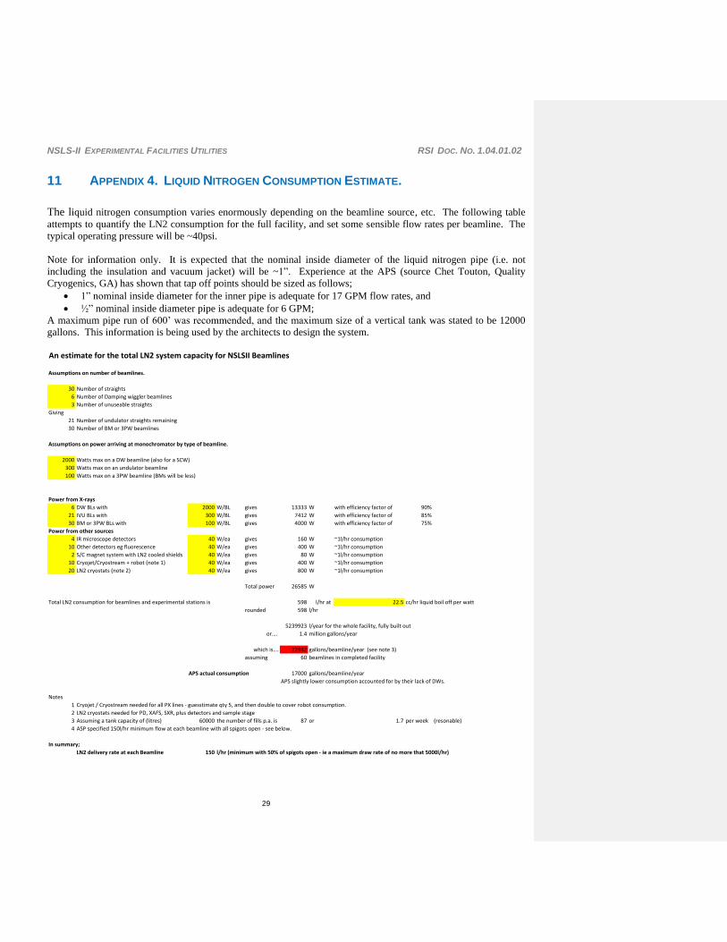
11 APPENDIX 4. LIQUID NITROGEN CONSUMPTION ESTIMATE.
The liquid nitrogen consumption varies enormously depending on the beamline source, etc. The following table
attempts to quantify the LN2 consumption for the full facility, and set some sensible flow rates per beamline. The
typical operating pressure will be ~40psi.
Note for information only. It is expected that the nominal inside diameter of the liquid nitrogen pipe (i.e. not
including the insulation and vacuum jacket) will be ~1”. Experience at the APS (source Chet Touton, Quality
Cryogenics, GA) has shown that tap off points should be sized as follows;
1” nominal inside diameter for the inner pipe is adequate for 17 GPM flow rates, and
½” nominal inside diameter pipe is adequate for 6 GPM;
A maximum pipe run of 600’ was recommended, and the maximum size of a vertical tank was stated to be 12000
gallons. This information is being used by the architects to design the system.
An estimate for the total LN2 system capacity for NSLSII Beamlines
Assumptions on number of beamlines.
30 Number of straights
6 Number of Damping wiggler beamlines
3 Number of unuseable straights
Giving
21 Number of undulator straights remaining
30 Number of BM or 3PW beamlines
Assumptions on power arriving at monochromator by type of beamline.
2000 Watts max on a DW beamline (also for a SCW)
300 Watts max on an undulator beamline
100 Watts max on a 3PW beamline (BMs will be less)
Power from X-rays
6 DW BLs with 2000 W/BL gives 13333 W with efficiency factor of 90%
21 IVU BLs with 300 W/BL gives 7412 W with efficiency factor of 85%
30 BM or 3PW BLs with 100 W/BL gives 4000 W with efficiency factor of 75%
Power from other sources
4 IR microscope detectors 40 W/ea gives 160 W ~1l/hr consumption
10 Other detectors eg fluorescence 40 W/ea gives 400 W ~1l/hr consumption
2 S/C magnet system with LN2 cooled shields 40 W/ea gives 80 W ~1l/hr consumption
10 Cryojet/Cryostream + robot (note 1) 40 W/ea gives 400 W ~1l/hr consumption
20 LN2 cryostats (note 2) 40 W/ea gives 800 W ~1l/hr consumption
Total power 26585 W
Total LN2 consumption for beamlines and experimental stations is 598 l/hr at 22.5 cc/hr liquid boil off per watt
rounded 598 l/hr
5239923 l/year for the whole facility, fully built out
or…. 1.4 million gallons/year
which is…. 22982 gallons/beamline/year (see note 3)
assuming 60 beamlines in completed facility
APS actual consumption 17000 gallons/beamline/year
APS slightly lower consumption accounted for by their lack of DWs.
Notes
1 Cryojet / Cryostream needed for all PX lines - guesstimate qty 5, and then double to cover robot consumption.
2 LN2 cryostats needed for PD, XAFS, SXR, plus detectors and sample stage
3 Assuming a tank capacity of (litres) 60000 the number of fills p.a. is 87 or 1.7 per week (resonable)
4 ASP specified 150l/hr minimum flow at each beamline with all spigots open - see below.
In summary;
LN2 delivery rate at each Beamline 150 l/hr (minimum with 50% of spigots open - ie a maximum draw rate of no more that 5000l/hr)
NSLS-II EXPERIMENTAL FACILITIES UTILITIES RSI DOC. NO. 1.04.01.02
30
12 APPENDIX 5. GASEOUS NITROGEN AND COMPRESSED AIR CONSUMPTION
ESTIMATE.
The consumption of compressed air is relatively small, and mainly intermittent. Typically a ½” nominal inside
diameter pipe is adequate, with a typical supply pressure of 80-100 psi.
Typical devices on a beamline requiring compressed air include:
Gate valves
Shutters
Possible air bearing for the IXS spectrometer(s) – comparison with SPRing8 data showed this was a very
low flow rate, connections being made with 4 x 6mm diameter plastic tubes.
Air bearings for PX beamline goniometers.
The consumption of compressed nitrogen is very small, and intermittent. Typically a ½” nominal inside diameter
pipe is adequate, with a typical supply pressure of ~30 psi.
Typical devices on a beamline requiring nitrogen gas include:
Purge devices (for IR microscopes)
Chambers requiring inert gas
Vacuum section bleed-ups
Experiments requiring nitrogen gas as an inert medium.
13 APPENDIX 6. TEMPERATURE SENSORS BACKGROUND INFORMATION.
All hutches and cabins shall be fitted with ambient temperature sensors in a small ventilated enclosure.
Temperature sensor type TBD
The sensors shall be wired back to the beamline control racks (outside the hutch)
The sensors can be used for monitoring and/or control of hutch temperature as required.
14 APPENDIX 7. OXYGEN DEPLETION ALARMS BACKGROUND INFORMATION.
Oxygen depletion alarms shall be fitted to all hutches or cabins where LN2 or gaseous nitrogen is (or could be)
present. The hazard is possible with a simple small Dewar in a potentially enclosed space; however, the hazard
becomes significantly greater with plumbed liquid nitrogen where a line rupture could lead to the spillage of
dangerous volumes of liquid.
Care need to be taken to ensure that the ODH sensor is sensitive to nitrogen and helium gases.
The sensors shall be wall mounted at approx 1-2m height (in accordance with the manufacturer’s instructions) with
an alarm external to the hutch or cabin.
The budgeted cost of Oxygen depletion sensors is ~$2000/enclosure, or about $4000/beamline max.
A "standard" stand alone system covering a single experiment station, cabin or FOE has a typical historical cost of
~$2500 per cabin, this includes a strobe/siren, and a spare head (aim for one spare head per four installed heads),
and commissioning work (as well as the first year of calibration, after which facility staff must do scheduled
maintenance). Facility staff or utilities contractors can do the installation which is simple, and requires only about
10m of standard instrument cable (and takes less than 4 hours per hutch).
Additionally, the alarm signal needs to be brought into either the Control Room (building 725) and/or the
Operations Coordinator (Ring building) room so that a response and investigation can take place.
A system for a small laboratory complex (e.g. IR cabins which may have a number of separate rooms) costs
~$6,000 per system including strobe/siren and the rack mounting controller with four detector heads.
A company in California http://www.rkiinstruments.com/ offers competitive products at almost exactly half of
the prices given above, for the same scope. They were also very helpful.