nato standard aep-893 nato unclassified 4. source documents the following rules and standards have...
TRANSCRIPT

NATO UNCLASSIFIED
NATO UNCLASSIFIED
NATO STANDARD
AEP-89
Unmanned Aerial Vehicle (UAV) Systems Airworthiness Requirements (USAR) for Light Vertical Take Off and
Landing (VTOL) Aircraft
Edition A Version 1
MONTH YEAR
NORTH ATLANTIC TREATY ORGANIZATION
ALLIED AIR TRAFFIC MANAGEMENT PUBLICATION
Published by the NATO STANDARDIZATION AGENCY (NSA)
© NATO/OTAN

NATO UNCLASSIFIED
NATO UNCLASSIFIED
INTENTIONALLY BLANK

NATO UNCLASSIFIED
NATO UNCLASSIFIED
NORTH ATLANTIC TREATY ORGANIZATION (NATO)
NATO STANDARDIZATION AGENCY (NSA)
NATO LETTER OF PROMULGATION

NATO UNCLASSIFIED
NATO UNCLASSIFIED
INTENTIONALLY BLANK

NATO UNCLASSIFIED AEP-89
I NATO UNCLASSIFIED
RESERVED FOR NATIONAL LETTER OF PROMULGATION

NATO UNCLASSIFIED AEP-89
II NATO UNCLASSIFIED
INTENTIONALLY BLANK

NATO UNCLASSIFIED
RECORD OF RESERVATIONS
CHAPTER RECORD OF RESERVATION BY NATIONS
Note: The reservations listed on this page include only those that were recorded at time of promulgation and may not be complete. Refer to the NATO Standardization Database for the complete list of existing reservations.

NATO UNCLASSIFIED AEP-89
2 NATO UNCLASSIFIED
INTENTIONALLY BLANK

NATO UNCLASSIFIED AEP-89
3 NATO UNCLASSIFIED
RECORD OF SPECIFIC RESERVATIONS [nation] [detail of reservation]
Note: The reservations listed on this page include only those that were recorded at time of promulgation and may not be complete. Refer to the NATO Standardization Database for the complete list of existing reservations.

NATO UNCLASSIFIED AEP-89
4 NATO UNCLASSIFIED
INTENTIONALLY BLANK

NATO UNCLASSIFIED AEP-89
5 NATO UNCLASSIFIED
UAV Systems Airworthiness Requirements (USAR) Vertical Take Off and Landing (VTOL)
TABLE OF CONTENTS
1. Scope ................................................................................................................................................. 1 2. Introduction ....................................................................................................................................... 1 3. Type design airworthiness evidence................................................................................................ 2 4. Source documents ............................................................................................................................ 3 5. Restricted Certification ..................................................................................................................... 3 6. Requirements ..................................................................................................................................... 3 ER.1 System integrity ........................................................................................................................ 4 ER.1.1 Structures and materials .......................................................................................................... 6 ER.1.2 Propulsion ............................................................................................................................... 22 ER.1.3 Systems and equipment ........................................................................................................ 30 ER.1.4 Continued airworthiness of the Light VTOL UAV ................................................................ 40 ER.2 Airworthiness aspects of system operation ......................................................................... 41 ER.3 Organisations ......................................................................................................................... 57 ANNEX A Terms and Definitions ……………………………………………………………………..A-1 ANNEX B Landing conditions for conventional landing gear configurations (where
applicable) .................................................................................................................................... B-1 ANNEX C Spark and compression ignition reciprocating engines ........................................ C-1 ANNEX D Electric engines ......................................................................................................... D-1 ANNEX E Turbine engines ........................................................................................................ E-1 ANNEX F Verticle lift elements and drive systems ...................................................................F-1 ANNEX G Hazard Reference System ........................................................................................ G-1 ANNEX H Stability and Response assessment guidance ....................................................... H-1 ANNEX I The Safety Management Plan ..................................................................................... I-1 ANNEX J Guidelines for airworthiness requirements applicable to Light VTOL UAV below
the 66J impact energy ................................................................................................ J-1

NATO UNCLASSIFIED
B-1 NATO UNCLASSIFIED
1. Scope
This document contains the minimum set of technical airworthiness requirements intended for the airworthiness certification of Light VTOL UAV with a maximum take-off weight not greater than 150 kg and an impact energy1 greater than 66 J (49 ft-lb) that intend to regularly operate in non-segregated airspace.
The lower limit is established according to available blunt trauma studies showing that below this level it is reasonably expected that a fatal injury should not occur if the Light VTOL UAV strikes an unprotected person. It is recognized that 66 J is a conservative value based on current research that will be reviewed after further investigation.
For Light VTOL UAV below the 66J impact energy threshold, it is reasonable that a number of requirements can be relaxed. Specific airworthiness requirements must be agreed with the Certifying Authority on a case-by-case basis. Annex J of this document provides applicable guidelines, that are not limited to VTOL aspects.
2. Introduction
Due to the large variety of possible configurations and technology in this category of Light VTOL UAV and the fact that many of these systems are architecturally simple, this STANAG has been developed with the following objectives.
- require no more than the minimum amount of certification evidence that is needed to substantiate an acceptable level of airworthiness;
- address all design attributes which may endanger safety;
1 The impact energy must be calculated using the worst case terminal velocity based on the foreseeable failure conditions, as agreed with the Certifying Authority.
- be flexible by being non-prescriptive, in order not to limit the design solutions (i.e., address issues instead of prescribing solutions).
It has been considered that a pure complete traditional prescriptive set of airworthiness codes (e.g. CSs, FARs) could not fulfil this objective, and it could not be derived from existing civil or military regulations applicable to manned aircraft. Therefore, a hybrid approach has been established, which combines a set of conventional airworthiness codes requirements with other types of qualitative criteria aimed to achieve a high level of confidence that the type design is airworthy (e.g. through process evidence or design criteria).
Creating this hybrid approach, the top-level starting point is the set of the Military Essential Requirements for Airworthiness. This STANAG also establishes means to comply with each of these mandatory minimum essential requirements in order to obtain a Type Certificate (or equivalent document) for Light VTOL UAV with Maximum Take Off Weight of 150 kg, or less, for flight in non-segregated airspace.
Throughout this document, the term ‘Type Certificate’ refers to any document issued by a National Certifying Authority that, within the regulatory framework of that Nation, certifies compliance as determined by the National Certifying Authority with this STANAG.
It is recognized that 'sense and avoid' is a key enabling issue for Light VTOL UAV operations. The derivation and definition of 'sense and avoid' requirements is primarily an operational issue and hence outside the scope of this STANAG. However, once these requirements are clarified, any system designed and installed to achieve these objectives shall be considered as an

NATO UNCLASSIFIED AEP-89
2 NATO UNCLASSIFIED
item of installed equipment within a Light VTOL UAV.
3. Type design airworthiness evidence
The Applicant must provide to the Certifying Authority any type of verifiable evidence that the system is designed to be airworthy for its intended purpose through its lifetime.
The Applicant should create comprehensive arguments, supported by a body of evidence, to demonstrate how the mandatory Essential Requirements for Airworthiness have been met and to provide confidence in the airworthiness of the Light VTOL UAV type design. The evidence could consist of one or more forms of the following types.
• direct evidence from analysis; • direct evidence from demonstration (rig
testing, representative prototype ground and flight operation, operational experience);
• direct quantitative safety evidence; • direct qualitative safety evidence; • direct evidence from hazard risk
management; • direct evidence extracted from the
design review process; • direct technical description of design
features and system functions; • direct qualitative evidence of good
design (e.g. design criteria and practices);
• process evidence (e.g. Design Assurance Levels allocation as per ARP-4754; Safety Management System processes) showing good Light VTOL UAV life-cycle safety issues management;
• any other quantitative and/or qualitative compelling argument provided to the Certifying Authority in order to demonstrate compliance with mandatory Essential Requirements for Airworthiness.
Consideration of design criteria and airworthiness management processes is as important as compliance with detailed codes, where applicable, and may constitute a certification credit giving the Certifying Authority the necessary confidence and level of trust that the result of the design activity is an airworthy Light VTOL UAV. In other words, behind this STANAG is the firm belief that the verification of design criteria, safety management plans, and technical qualitative arguments constitute an additional means in order to demonstrate compliance with high-level Essential Requirements for Airworthiness, which are general and qualitative in nature. Therefore, consideration of additional evidence, other than conventional quantitative arguments, is an effective strategy that may be used by the Authority to certify the airworthiness of a Light VTOL UAV for which the variety of possible configurations and technical design solutions may sometimes compromise compliance with a detailed set of airworthiness codes.

NATO UNCLASSIFIED AEP-89
3 NATO UNCLASSIFIED
4. Source documents
The following rules and standards have been used as source material to derive this STANAG:
• STANAG 4671 (UAV Systems Airworthiness Requirements for North Atlantic Treaty Organization Military UAV Systems),
• Draft STANAG 4702 (Rotary Wing UAV Airworthiness Requirements)
• Draft STANAG 4703 (Light UAV Systems Airworthiness Requirements for North Atlantic Treaty Organization (NATO) Military UAV Systems)
• CS 27 (Certification Specifications for Small Rotorcraft)
• CS VLR (Certification Specifications for Very Light Rotorcraft)
• • DEF STAN 00-56 (Safety Management
Requirements for Defence Systems).
5. Restricted Certification
Non-segregated airspace contains regions of densely populated areas and sparsely populated areas. It is therefore possible that Light VTOL UAV not meeting all the objectives in this STANAG will be airworthy to fly in sparsely populated areas of non-segregated airspace as determined by the Certifying Authority.
Non-compliance with some requirements of this STANAG may be negotiated on a case-by-case basis depending on particular Light VTOL UAV design and envisaged operating restrictions in the framework of a Restricted Type Certification.
Any non-compliance or operating restriction must be agreed with the Certifying Authority, tracked and identified in the Certificate Data Sheet (or equivalent).
6. Requirements
The following section provides the Certification Basis requirements for Light VTOL UAV in the form of a three column table in which:
I. the first column expresses the mandatory Minimum Essential Requirements for Airworthiness;
II. the second column presents a detailed argument to elaborate the Essential Requirements in the first column into an Airworthiness Basis for a specific type of Light VTOL UAV;
III. the third column presents an acceptable set of evidence that may be provided to the Certifying Authority in order to demonstrate compliance with the detailed arguments in the second column.
Compliance with the Airworthiness Essential Requirements (first column) is mandatory and must be demonstrated through a comprehensive set of arguments (of the type mentioned in §3).
Unless stated as a requirement (i.e. "must" statements), the detailed arguments may be interpreted as Applicable Means of Compliance with the Airworthiness Essential Requirements. The Applicant should follow these requested arguments. Nevertheless, if it is difficult for a particular application to comply with the detailed request, the Applicant may propose to the Certifying Authority compelling alternative arguments with a rational demonstration that a comparable level of safety is assured.

NATO UNCLASSIFIED
B-4 NATO UNCLASSIFIED
NOTE DETAILED ARGUMENTS: Compliance with the Essential Requirements may be shown by the Applicant through these detailed arguments or by any other argument which meets the intent behind them with a comparable level of safety, to be agreed with the Certifying Authority, wherever a “should” statement appears.
AIRWORTHINESS ESSENTIAL REQUIREMENTS
DETAILED ARGUMENTS MEANS OF EVIDENCE
ER.1 System integrity
System integrity must be assured for all anticipated flight conditions and ground operations for the operational life of the Light VTOL UAV. Compliance with all requirements must be shown by assessment or analysis, supported, where necessary, by tests.
UL.0 The Applicant must identify the design usage spectrum as the set of all the foreseen operational conditions of the Light VTOL UAV: - typical design missions; - in-flight operation conditions; - on-ground operation conditions; - operational modes (automatic, speed-hold, altitude hold, direct manual, etc.); - take-off / launch / ramp conditions; - landing / recovery conditions; - locations and platforms (e.g. land vehicle, water vessel, aircraft, building, etc.) from which launch,
command and control, and recovery operations will be performed (e.g., land, littoral/maritime, air, ); - number of air vehicles to be operated simultaneously; - transport conditions (define the transportation and storage environment of the Light VTOL UAV like
bag, package, truck or whatever is required); - operating environmental conditions:
- natural climate (altitude, temperature, pressure, humidity, wind, rainfall rate, lightning, ice, salt fog, fungus, hail, bird strike, sand and dust, etc.);
- electromagnetic environmental effects (electromagnetic environment among all sub-systems and equipment, electromagnetic effects caused by external environment, electromagnetic interference among more than one Light VTOL UAVS operated in proximity);
- lighting conditions (e.g., day, night, dawn, dusk, mixed, etc.); - identify all the possible mass configurations (minimum and maximum flying weight, empty CG, most
forward CG, most rearward CG must be identified).
In all the identified conditions the Applicant must verify to the satisfaction of the Certifying Authority the requirements of the following paragraphs.
ME0 Description of the design usage spectrum

NATO UNCLASSIFIED AEP-89
5 NATO UNCLASSIFIED
AIRWORTHINESS ESSENTIAL REQUIREMENTS
DETAILED ARGUMENTS MEANS OF EVIDENCE
UL.1 The Applicant must identify design criteria, standards and practices used to design Light VTOL UAV structure, engine, rotor blades, shrouded rotor blades, ducted fan, propeller, (vertical lifting element(s)) and;
UL1.1 Main vertical lifting element(s) speed and pitch limits
(a) Main vertical lifting element(s) speed limits. A range of main vertical lifting element(s) speeds must be established so that:
(1) With power-on, provides adequate margin to accommodate the variations in vertical lifting element(s) speed occurring in any appropriate manoeuvre, and is consistent with the kind of governor or synchronizer used; and
(2) With power-off, if autorotation capability is implemented, allows each appropriate autorotative manoeuvre to be performed throughout the ranges of airspeed and weight for which certification is requested.
(b) Normal main vertical lifting element(s) high pitch limits (power-on). For Light VTOL UAV, except Light Helicopter UAV required to have a main vertical lifting element(s) low speed warning under subparagraph (e ) It must be shown, with power-on and without exceeding approved engine maximum limitations that main vertical lifting element(s) speeds substantially less than the minimum approved main vertical lifting element(s) speed will not occur under any sustained flight condition. This must be met by:
(1) Appropriate setting of the main vertical lifting element(s) (i.e. rotor, etc.) high pitch stop; or
(2) Adequate means to prevent unsafe main vertical lifting element(s) speeds.
(c) Normal main vertical lifting element(s) low pitch limits (power-off). If autorotation capability is implemented, it must be shown, with power-off, that:
(1) The normal main vertical lifting element(s) low pitch limit provides sufficient vertical lifting element(s) speed, in any autorotative condition, under the most critical combinations of weight and airspeed; and
(2) Overspeeding of the vertical lifting element(s) is protected by the flight control system in compliance with UL 2.4
(d) Emergency high pitch. If the main vertical lifting element(s) high pitch stop is set to meet subparagraph (b)(1), and if that stop cannot be exceeded in normal mode, additional pitch may be made available for emergency use.
ME1 A description of the design criteria to be used must be submitted to the Certifying Authority, in order to gather a sufficient level of trust

NATO UNCLASSIFIED AEP-89
6 NATO UNCLASSIFIED
AIRWORTHINESS ESSENTIAL REQUIREMENTS
DETAILED ARGUMENTS MEANS OF EVIDENCE
(e) Main rotor low speed warning for Light Helicopter UAVs. For each single-engine Light Helicopter UAV, and each multi-engine Light Helicopter UAV that does not have an approved device that automatically increases power on the operating engines when one engine fails, there must be a main rotor low speed warning which meets the following requirements:
(1) The warning must be furnished to the operator in the Light VTOL UAV control station in all flight conditions, including power-on flight and, if autorotation capability is implemented, power-off flight when the speed of a main rotor approaches a value that can jeopardize safe flight.
(2) The warning must be clear and distinct under all conditions, and must be clearly distinguishable from all other warnings. A visual device that requires the attention of the operator is not acceptable by itself.
(3) If a warning device is used, the device must automatically de-activate and reset when the low-speed condition is corrected. If the device has an audible warning, it must also be equipped with a means for the operator to manually silence the audible warning before the low-speed condition is corrected.
ER.1.1 Structures and materials
The integrity of the structure must be ensured throughout, and by a defined margin beyond, the operational envelope for the Light VTOL UAV, including its propulsion system, and maintained for the operational life of the Light VTOL UAV.
UL.2 Loads The Applicant must define and justify with a rationale a positive margin beyond the maximum operating envelope, in order to establish the design loads.
(a) Strength requirements are specified in terms of limit loads (the maximum loads to be expected in service) and ultimate loads (limit loads multiplied by prescribed factors of safety). Unless otherwise provided, prescribed loads are limit loads.
(b) Unless otherwise provided, the specified air, ground, and water loads must be placed in equilibrium with inertia forces, considering each item of mass in the Light VTOL UAV. These loads must be distributed to closely approximate or conservatively represent actual conditions.
(c) If deflection under load would significantly change the distribution of external or internal loads, this redistribution must be taken into account.Strength and deformation
UL2.1 Strength and Deformation
(a) The structure must be able to support limit loads without detrimental permanent deformation. At any load up to limit loads, the deformation may not interfere with safe operation.
(b) The structure must be able to support ultimate loads without failure. This must be shown by-
(1) Applying ultimate loads to the structure in a static test for at least 3 seconds; or
(2) Dynamic tests simulating actual load application Proof of Structure
ME2 A description of the rationale for the design loads margins to be included in Design Criteria in ME1

NATO UNCLASSIFIED AEP-89
7 NATO UNCLASSIFIED
AIRWORTHINESS ESSENTIAL REQUIREMENTS
DETAILED ARGUMENTS MEANS OF EVIDENCE
UL2.2 Proof of Structure
a) Compliance with the strength and deformation requirements of this Subpart must be shown for each critical loading condition accounting for the environment to which the structure will be exposed in operation. Structural analysis (static or fatigue) may be used only if the structure conforms to those structures for which experience has shown this method to be reliable. In other cases, substantiating load tests must be made. (See Annex F)
(b) Proof of compliance with the strength requirements of this Subpart must include -
(1) Dynamic and endurance tests of vertical lifting element(s), vertical lifting element(s) drives, and vertical lifting element(s) controls;
(2) Limit load tests of the control system, including control surfaces;
(3) Operation tests of control system;
(4) Flight stress measurement tests;
(5) Landing gear drop tests; and (6) Any additional tests required for new or unusual design features;
UL2.3 Design limitations
The following values and limitations must be established to show compliance with the structural requirements of this Subpart:
(a) The design maximum weight.
(b) The main vertical lift element rpm ranges power-on and power-off.
(c) The maximum forward speeds for each main vertical lift element rpm within the ranges determined in sub-paragraph (b).
(d) The maximum rearward and sideward flight speeds.
(e) The centre of gravity limits corresponding to the limitations determined in sub-paragraphs (b), (c), and (d).
(f) The rotational speed ratios between powerplant and each connected rotating component.
(g) The positive and negative limit manoeuvring load factors.

NATO UNCLASSIFIED AEP-89
8 NATO UNCLASSIFIED
AIRWORTHINESS ESSENTIAL REQUIREMENTS
DETAILED ARGUMENTS MEANS OF EVIDENCE
UL2.4 Factor of Safety
The factor of safety of ≥1.5 (for structure whose failure would lead to a Hazardous or more serious failure condition) or ≥1.25 (for other structure)UL2.3 should be multiplied by a further special factor in the following cases:
- ≥2.0 on castings,
- ≥1.15 on fittings,
- ≥2.0 on bearings at bolted or pinned joints subject to rotation,
- ≥4.45 on control surface hinge-bearing loads except ball and roller bearing hinges,
- ≥2.2 on push-pull control system joints,
- in composite structures, if A or B allowables for hot and wet conditions are not statistically justified (as per UL9.2 and UL9.3), the following special factors should be used: ≥1.2 for moisture conditioned specimen tested at maximum service temperature, providing that a well established manufacturing and quality control procedure is used; or ≥1.5 for specimen tested with no specific allowance for moisture and temperature;
- ≥1.5 for attachments in frequently assembled and disassembled structural parts, to cover potential deterioration in service; alternatively, this factor is not needed if a test reproducing the required number of assemble/disassemble operations demonstrates no degradation of structural integrity;
- in certain circumstances the Certifying Authority may chose to use a further justified special factor >1 to cover any uncertainty not previously mentioned.
-
ER.1.1.1 All parts of the Light VTOL UAV, the failure of which could reduce the structural integrity, must comply with the following conditions without detrimental deformation or failure. This includes all items of significant mass and their means of restraint.
UL.3 The Applicant must identify Primary Structural Elements (PSEs) for which failure would lead to hazardous or more serious effects (e.g. primary Light VTOL UAV structure bearing aerodynamic, inertial and propulsion forces; control surface and control system structural elements, control surface hinges; structural elements of systems used in launching and recovery phases).
ME3 Description of the PSEs
UL.4 For each PSE identified in UL.3 and for all on-board equipment, the structure must be proven according to the following criteria: - no detrimental deformation against the Limit Loads obtained by multiplying the maximum
operational loads identified under UL.5 to UL.6 by the limit load factors of safety in UL.2, and
ME4 Proof of Structure by a compelling combination of conservative analyses

NATO UNCLASSIFIED AEP-89
9 NATO UNCLASSIFIED
AIRWORTHINESS ESSENTIAL REQUIREMENTS
DETAILED ARGUMENTS MEANS OF EVIDENCE
- no rupture against the Ultimate Loads obtained by multiplying the maximum operational loads identified under UL.5 to UL.6 by the ultimate load factors of safety in UL.2;
- the control system is free from interference, jamming, excessive friction and excessive deflection when the control system limit loads are applied to the controls and the surfaces; additionally the control system stops must withstand those loads.
For non-PSEs, the structure must be proven according to the following criterion: - no rupture against the Ultimate Loads obtained by multiplying the maximum operational loads
identified under UL.5 to UL.6 by the ultimate load factors of safety in UL.2.
and tests
ER.1.1.1.1 All combinations of load reasonably expected to occur within, and by a defined margin beyond, the weights, centre of gravity range, operational envelope and life of the Light VTOL UAV must be considered. This includes loads due to gusts, manoeuvres, pressurisation, movable surfaces, control and propulsion systems both in flight and on the ground.
UL.5 Flight loads
(a) The flight load factor must be assumed to act normal to the longitudinal axis of the Light VTOL UAV, and to be equal in magnitude and opposite in direction to the Light VTOL UAV inertia load factor at the centre of gravity.
(b) Compliance with the flight load requirements of this Subpart must be shown-
(1) At each weight from the design minimum weight to the design maximum weight; and
(2) With any practical distribution of disposable load within the operating limitations in the Light VTOL UAV Flight Manual.
UL5.1. Limit Manoeuvring Load Factors
The Light VTOL UAV must be designed for-
(a) A limit manoeuvring load factor ranging from a positive limit of 3.5 to a negative limit of -1.0; or loads approved by the certifying authority based on the usage spectrum in UL.0
(b) Any positive limit manoeuvring load factor not less than 2.0 and any negative limit manoeuvring load factor of not less than -0.5 for which-
(1) The probability of being exceeded is shown by analysis and flight tests to be extremely remote; and
(2) The selected values are appropriate to each weight condition between the design maximum and design minimum weights.
UL5.2. Resultant limit manoeuvring loads
The loads resulting from the application of limit manoeuvring load factors are assumed to act at the centre of each vertical lifting element(s) hub and each auxiliary lifting surface, and to act in directions,
ME5 Assumptions and analysis of the design loads in-flight

NATO UNCLASSIFIED AEP-89
10 NATO UNCLASSIFIED
AIRWORTHINESS ESSENTIAL REQUIREMENTS
DETAILED ARGUMENTS MEANS OF EVIDENCE
and with distributions of load among the vertical lifting element(s) and auxiliary lifting surfaces, so as to represent each critical manoeuvring condition, including power-on and power-off flight with the maximum design vertical lifting element(s) tip speed ratio. The vertical lifting element(s) tip speed ratio is the ratio of the Light VTOL UAV flight velocity component in the plane of the vertical lifting element(s) disc to the rotational tip speed of the vertical lifting element(s) blades, and is expressed as follows:
μ = V cos a ΩR where-
V = The airspeed along the flight path (m/s);
a = The angle between the projection, in the plane of symmetry, of the axis of no feathering and a line perpendicular to the flight path (radians, positive when the axis is pointing aft);
Ω = The angular velocity of the vertical lifting element(s) (radians per second); and
R = The vertical lifting element(s) radius (m).
UL5.3. Yawing conditions
(a) Each Light VTOL UAV must be designed for the loads resulting from the manoeuvres specified in subparagraphs (b) and (c) with-
(1) Unbalanced aerodynamic moments about the centre of gravity which the aircraft reacts to in a rational or conservative manner considering the principal masses furnishing the reacting inertia forces; and
(2) Maximum main vertical lift element speed.
(b) To produce the load required in sub-paragraph(a), in unaccelerated flight with zero yaw, at forward speed from zero up to 0.6 VNE-
(1) Displace the directional control suddenly to the maximum deflection limited by the control stop or by the FCS.
(2) Attain a resulting sideslip angle or 90°, whichever is less; and
(3) Return the directional control suddenly to neutral.
(c) To produce the load required in sub-paragraph
(a), in unaccelerated flight with zero yaw, at forward speeds from 0.6 VNE up to VNE or VH, whichever is less-

NATO UNCLASSIFIED AEP-89
11 NATO UNCLASSIFIED
AIRWORTHINESS ESSENTIAL REQUIREMENTS
DETAILED ARGUMENTS MEANS OF EVIDENCE
(1) Displace the directional control suddenly to the maximum deflection limited by the control stops or by the FCS.
(2) Attain a resulting sideslip angle or 15°, whichever is less, at the lesser speed of VNE or VH.
(3) Vary the sideslip angles of sub-paragraphs (b)(2) and (c)(2) directly with speed; and
(4) Return the directional control suddenly to neutral.
UL5.4. Gust loads
The Light VTOL UAV must be designed to withstand loads at each critical airspeed including hovering.
Gust values should be determined by rational analysis of the intended use of the Light VTOL UAV, considering the design operational altitude level and the cruise speed (consistent with the design usage spectrum defined in UL.0). In absence of an alternative compelling rationale, the following should be used; the loads resulting from a vertical gust of 9.1 m/s (30 ft/s)..
Potential limitations may be established, where applicable, and documented in operating manuals, taking due account of the design usage spectrum as per UL.0.
UL5.5. Engine Torque
(a) For turbine engines, the limit torque may not be less than the highest of:
(1) The mean torque for maximum continuous power multiplied by 1.25;
(2) The torque required in Annex F.
(3) The torque imposed by sudden engine stoppage due to malfunction or structural failure (such as compressor jamming).
(b) For reciprocating engines, the limit torque may not be less than the mean torque for maximum continuous power multiplied by:
(1) 1.33, for engines with five or more cylinders; and
(2) Two, three, and four, for engines with four, three, and two cylinders, respectively.
UL5.6. Unsymmetrical loads
(a) Horizontal tail surfaces and their supporting structure must be designed for unsymmetrical loads arising from yawing and vertical lifting element(s) wake effects in combination with the prescribed flight

NATO UNCLASSIFIED AEP-89
12 NATO UNCLASSIFIED
AIRWORTHINESS ESSENTIAL REQUIREMENTS
DETAILED ARGUMENTS MEANS OF EVIDENCE
conditions.
(b) To meet the design criteria of sub-paragraph (a), in the absence of more rational data, both of the following must be met: (1) 100 % of the maximum loading from the symmetrical flight conditions acts on the surface on one side of the plane of symmetry and no loading acts on the other side.
(2) 50 % of the maximum loading from the symmetrical flight conditions acts on the surface on each side of the plane of symmetry but in opposite directions.
(c) For empennage arrangements where the horizontal tail surfaces are supported by the vertical tail surfaces, the vertical tail surfaces and supporting structure must be designed for the combined vertical horizontal surface loads resulting from each prescribed flight condition, considered separately. The flight conditions must be selected so the maximum design loads are obtained on each surface. In the absence of more rational data, the unsymmetrical horizontal tail surface loading distributions described in this paragraph must be assumed.
UL5.7. Recovery with parachute (for applications with normal parachute landing operations) - The loads during recovery phase due to deployment of the parachute and consequent aerodynamic and inertial loads from the worst operational condition of weight and flight envelope must be determined.
UL5.8. Recovery with parachute (for applications in which parachute recovery is an emergency condition only) –The loads due to deployment of the parachute and consequent aerodynamic and inertial loads from the worst operational condition of weight and flight envelope must be determined as an ultimate condition only.
UL5.9. Any other specific load condition in-flight not included in the previous paragraphs.
UL5.10. Control System Loads
UL5.10.1 Control System Loads
Each control system including its supporting structure, must be designed as follows:
(1) The system must withstand loads resulting from the limit control forces derived from UL6.2.
(2) Notwithstanding sub-paragraph (b)(3), when power-operated actuator controls or power boost controls are used, the system must also withstand the loads resulting from the force output of each normally energized power device, including any single power boost or actuator system failure.
(3) If the system design or the normal operating loads are such that a part of the system cannot react to the limit forces derived from UL6.2, that part of the system must be designed to withstand the maximum

NATO UNCLASSIFIED AEP-89
13 NATO UNCLASSIFIED
AIRWORTHINESS ESSENTIAL REQUIREMENTS
DETAILED ARGUMENTS MEANS OF EVIDENCE
loads that can be obtained in normal operation. The minimum design loads must, in any case, provide a rugged system for service use, including consideration of fatigue, jamming, ground gusts, control inertia and friction loads.
(4) If operational loads may be exceeded through jamming, ground gusts, control inertia, or friction, the system must withstand the limit control forces derived from UL6.2, without yielding.
UL5.10.2 Limit Control Forces and Torques
(a) In the control surface flight loading condition, the air loads on movable surfaces and the corresponding deflections need not exceed those that would result in flight from the application of any force occurring from the actuating device within the range derived from UL6.2 (b).
(b) The control system must be able to bear the maximum loads and torques generated by the actuating device.
UL5.10.3 Secondary Flight Control
Secondary flight controls (as defined in ANNEX A.2 Terms And Definitions) must be designed for the maximum forces that the actuating device is likely to apply to those controls.
UL5.10.4 Ground clearance: anti- torque device guard
(a) It must be impossible for the anti-torque device to contact the landing surface during a normal landing.
(b) If a guard is required to show compliance with sub-paragraph (a) -
(1) Suitable design loads must be established for the guard; and
(2) The guard and its supporting structure must be designed to withstand those loads.

NATO UNCLASSIFIED AEP-89
14 NATO UNCLASSIFIED
AIRWORTHINESS ESSENTIAL REQUIREMENTS
DETAILED ARGUMENTS MEANS OF EVIDENCE
UL.6 Ground loads
The Applicant must identify all maximum operational loads that the PSEs must withstand on the ground, considering external forces in equilibrium with inertial forces.
UL6.1 General, Ground Loads
(a) Loads and equilibrium. For limits ground loads-
(1) The limit ground loads obtained in the landing conditions in this Subpart must be considered to be
external loads that would occur in the VTOL UAV structure if it were acting as a rigid body; and
(2) In each specified landing condition, the external loads must be placed in equilibrium with linear and
angular inertia loads in a rational or conservative manner.
(b) Critical centres of gravity. The critical centres of gravity within the range for which certification is
requested must be selected so that the maximum design loads are obtained in each landing gear
element.
UL6.2 Ground loading conditions and assumptions
(a) For specified landing conditions, a design maximum weight must be used that is not less than the maximum weight. Vertical lifting element(s) lift may be assumed to act through the centre of gravity throughout the landing impact. This lift may not exceed two-thirds of the design maximum weight.
(b) Unless otherwise prescribed, for each specified landing condition, the Light VTOL UAV must be designed for a limit load factor of not less than the limit inertia load factor substantiated under ANNEX B.
UL6.3 Main vertical lifting element(s) structure
(a) Each main vertical lifting assembly (including but not limited to assembly of rotating components which includes the vertical lifting element(s) hub, blades, blade dampers, pitch control mechanisms, and all other parts which rotate with the assembly) must be designed as prescribed in this paragraph
(b) (Reserved)
(c) The vertical lifting element structure must be designed to withstand the limit manoeuvring load factor and the design gust loading conditions.
ME6 Assumptions and analysis of the design loads on-ground

NATO UNCLASSIFIED AEP-89
15 NATO UNCLASSIFIED
AIRWORTHINESS ESSENTIAL REQUIREMENTS
DETAILED ARGUMENTS MEANS OF EVIDENCE
(1) Critical flight loads.
(2) Limit loads occurring under normal conditions of autorotation. For this condition, the vertical lifting element rpm must be selected to include the effects of altitude.
(d) The main vertical lifting element structure must be designed to withstand loads simulating-
(1) For the vertical lifting element blades, hubs, and flapping hinges, the impact force of each blade against its stop during ground operation; and
(2) Any other critical condition expected in normal operation.
(e) The main vertical lifting element structure must be designed to withstand the limit torque at any rotational speed including zero. In addition-
(1) The limit torque need not be greater than the torque defined by a torque limiting device (where provided), and may not be less than the greater of-
(i) The maximum torque likely to be transmitted to the vertical lifting element structure in either direction; and
(ii) The limit engine torque specified in UL.5.5
(2) The limit torque must be distributed to the vertical lifting element blades in a rational manner.
UL6.4 Fuselage, landing gear, and vertical lifting element pylon structures
(a) Each fuselage, landing gear, and vertical lifting element pylon structure must be designed as prescribed in this paragraph. Resultant vertical lifting element forces may be represented as a single force applied at the vertical lifting element hub attachment point.
(b) Each structure must be designed to withstand:
(1) The critical loads prescribed in section UL 5
(2) The applicable ground loads prescribed in section UL6.1 and UL6.2.
(3) The loads prescribed in UL6.3.
(c) Auxiliary vertical lifting element thrust, and the balancing air and inertia loads occurring under accelerated flight conditions, must be considered.
(d) Each engine mount and adjacent fuselage structure must be designed to withstand the loads

NATO UNCLASSIFIED AEP-89
16 NATO UNCLASSIFIED
AIRWORTHINESS ESSENTIAL REQUIREMENTS
DETAILED ARGUMENTS MEANS OF EVIDENCE
occurring under accelerated flight and landing conditions, including engine torque.
UL6.5 Launch / Catapult (where applicable)
- For both the launch system and the Light VTOL UAV PSEs, determine a longitudinal load corresponding to the maximum continuous load factor applied by the launch system / operator at the maximum and minimum take-off weight.
- Demonstrate that either the assumptions for launching loads determination are sufficiently conservative or that the acceleration and the rate of change of acceleration (jerk) imposed by the launcher are controlled such that the Light VTOL UAV does not sustain damage during launch.
UL6.6 Landing impact at the maximum design weight
Taking into account the specific design usage spectrum as per UL.0, the worst combination of loads corresponding to all the reasonably possible scenarios of impact in the landing phase must be determined. For conventional landing gear configurations see Annex B as a reference.
UL6.7 Any other specific load condition on-ground not included in the previous paragraphs.
ER.1.1.1.2 Where applicable to the system, consideration must be given to the loads and likely failures induced by emergency landings either on land or water.
N/A
ER.1.1.1.3 Dynamic effects must be covered in the structural response to these loads.
UL.7 Structural dynamic load response – The airframe should be monitored in flight tests and ground tests in order to assess whether the dynamic response to flight and ground loads is relevant, or not, as agreed with the Certifying Authority. If the dynamic contribution in flight or ground operations is shown to be relevant, a dynamic response analysis should be performed using the most significant dynamic loading conditions.
ME7 A combination of tests and analyses

NATO UNCLASSIFIED AEP-89
17 NATO UNCLASSIFIED
AIRWORTHINESS ESSENTIAL REQUIREMENTS
DETAILED ARGUMENTS MEANS OF EVIDENCE
ER.1.1.2 The Light VTOL UAV must be free from any aero–servo-elastic instability and excessive vibration.
UL.8 Flutter and vibration
UL8.1 Flutter
Each aerodynamic surface of the Light VTOL UAV must be free from flutter under each appropriate speed and power condition.
UL8.2 Vibration
Each part of the Light VTOL UAV must be free from excessive vibration under each
appropriate speed and power condition.
ME8 A combination of assumptions, tests and analyses
ER.1.1.3 The manufacturing processes and materials used in the construction of the Light VTOL UAV must result in known and reproducible structural properties. Any changes in material performance related to the operational environment must be accounted for.
UL.9 The Applicant must identify the material allowables used in structure design, so that no structural part is under strength as a result of material variations or load concentration.
UL9.1 The sources for material allowables determination must be declared and agreed by the Certifying Authority.
UL9.2 The following criteria in choosing material allowables should be used.
- Where applied loads are eventually distributed through a single member within an assembly, the failure of which would result in the loss of the structural integrity of the component involved, the guaranteed minimum design mechanical properties (‘A’ values - value above which at least 99% of the population of values is expected to fall with a confidence of 95%) should be met. - Redundant structures, in which the failure of the individual elements would result in applied loads being safely distributed to other load carrying members, may be designed on the basis of the 90% probability values (‘B’ basis). - When the Applicant is unable to provide satisfactory statistical justification for A and B values, especially in the case of manufacturing of composite materials, an additional safety super factor should be applied to ensure that A/ B values are met.
Material properties handbooks like MMPDS-03, CMH-17 could be used.
UL9.3 Where temperature and moisture have significant effects on the material strength capabilities (e.g. composites), the allowable design values must be considered in the worst operational conditions (see also UL2.4).
ME9 Description of the used materials and their allowables. Evidence of compliance could be given in the Design Criteria of ME1.

NATO UNCLASSIFIED AEP-89
18 NATO UNCLASSIFIED
AIRWORTHINESS ESSENTIAL REQUIREMENTS
DETAILED ARGUMENTS MEANS OF EVIDENCE
UL.10 The Applicant must identify the materials and manufacturing processes used in the construction of the Light VTOL UAV and the criteria implemented to control materials performance variability among specimens. Manufactured parts, assemblies, and the complete Light VTOL UAV must be produced in accordance with the manufacturer’s Quality Management System, approved as per AS/EN-9100 certification or equivalent.
ME10 AS/EN-9100 Certification or equivalent.
ER.1.1.4 The effects of cyclic loading, environmental degradation, accidental and discrete source damage must not reduce the structural integrity below an acceptable residual strength level. All necessary instructions for ensuring continued airworthiness in this regard must be promulgated.
UL.11 Fatigue
UL11.1. Fatigue evaluation of flight structure
(a) General. Each portion of the flight structure (the flight structure includes vertical lifting element(s) vertical lifting element(s) drive systems between the engines and the vertical lifting element(s) hubs, controls, fuselage, landing gear and their related primary attachments) the failure of which could be catastrophic, must be identified and must be evaluated in subparagraph
(b), (c). The following apply to each fatigue evaluation:
(1) The procedure for the evaluation must be approved.
(2) The locations of probable failure must be determined.
(3) Inflight measurement must be included in determining the following:
(i) Loads or stresses in all critical conditions throughout the range of limitations in UL.2.3, except that manoeuvring load factors need not exceed the maximum values expected in operation.
(ii) The effect of altitude upon these loads or stresses.
(4) The loading spectra must be as severe as those expected in operation including ground-airground cycles. The loading spectra must be based on loads or stresses determined in sub-paragraph (a)(3).
(b) Fatigue tolerance evaluation. It must be shown that the fatigue tolerance of the structure ensures that the probability of catastrophic fatigue failure is extremely remote without establishing replacement times, inspection intervals or other procedures and listed in the instructions for continued airworthiness (see UL.39).
(c) Replacement time evaluation. It must be shown that the probability of catastrophic fatigue failure is extremely remote within a replacement time furnished in the instructions for continued airworthiness under the “airworthiness limitations” paragraph.
ME11 Structural design criteria (refer to ME1) and stress analysis.

NATO UNCLASSIFIED AEP-89
19 NATO UNCLASSIFIED
AIRWORTHINESS ESSENTIAL REQUIREMENTS
DETAILED ARGUMENTS MEANS OF EVIDENCE
UL11.2. There must be sufficient evidence that PSEs have strength capabilities to achieve an adequate safe-life.
UL11.2.1. For Aluminium and Steel Alloys, the use of stress levels less than half of the rupture tensile strength may be taken as sufficient evidence, in conjunction with good design practices to eliminate stress concentrations, that structural items have adequate safe-lives.
UL11.2.2. For wood, ANC-18 should be used as a reference.
UL11.2.3. For Composite materials, the use of strain levels compatible with the no-growth criterion for the Damage Tolerance (as per UL13.1.1 or UL13.1.2) may be taken as sufficient evidence, in conjunction with good design precautions to avoid the local development of out-of-plane stresses2, that structural items have adequate safe-lives.
UL.12 Protection of the structure against weathering, corrosion and wear, as well as suitable ventilation and drainage, must be provided as required.
ME12 Description of protection criteria against environmental degradation
UL.13 The Applicant must identify all reasonable accidental and discrete sources of damage relevant for the operational conditions and determine protection design features for each of them.
UL13.1 Impact damage on composite PSEs
For composite PSEs, it must be shown that delaminations or barely visible flaws related to impact damages realistically expected from manufacturing and service will not reduce the structural strength below ultimate load capability and will not grow.
The following alternative arguments are acceptable means to comply with this requirement.
UL13.1.1 For composite PSEs, a special factor ≥ 6.0 multiplying the factor of safety of UL2.3 could be used.
To demonstrate strength and damage tolerance for damaged critical design features the Certifying Authority may require tests at detail, sub-component or component levels.
UL13.1.2 Composite PSE parts could be designed not to exceed the following Damage
ME13 Description of protection criteria against accidental discrete damage sources and corresponding analyses and tests where applicable.
2 Corners, ply drop-off, stringer run-outs are of primary importance.

NATO UNCLASSIFIED AEP-89
20 NATO UNCLASSIFIED
AIRWORTHINESS ESSENTIAL REQUIREMENTS
DETAILED ARGUMENTS MEANS OF EVIDENCE
Tolerance Strains:
Loading Damage Tolerance Strain(με) Sandwich skin
Full Laminates with thickness ≤2 mm
Full Laminates with thickness > 2 mm
Tension 5000 5000 Compression 2600 3000 Shear 5200 6000
To demonstrate strength and damage tolerance for damaged critical design features, the Certifying Authority may require tests at detail, sub-component or component levels.
This allowable strain must be used in absence of a compelling argument in the choice of allowables in composite material, taking into account reduction of strength capabilities down to barely visible impact damage strength after impact.
Note - The damage tolerance strain values in the above table should only be used if the degradation of Hot Wet (HW) properties is less than 50% of the Room Temperature Dry (RTD) properties. Otherwise, a safety factor of 6.0 should be used.
Note - The above strain values may be increased if the Applicant shows by other evidence (e.g. analytical evidence; analysis with a representative composite material; specimen tests; repeated landing demonstration test in conjunction with composite inspections) that the typical damages within the design usage spectrum have no negative influence on the composite structure, including the consideration of material properties, possible impact zones, and protection layers, etc.
UL13.2 Bird strike
Bird strike protection for the Light VTOL UAV must be agreed with the Certifying Authority, according to the intended Light VTOL UAV size, use and technological constraints.
UL.14 The designed configuration must provide accessibility for PSEs and control system inspection, adjustment, maintenance and repair, where necessary.
ME14 Description of accessibility provisions
UL.15 The Applicant must promulgate all necessary instructions for ensuring continued airworthiness. ME15 Set of instructions for continued airworthiness to be

NATO UNCLASSIFIED AEP-89
21 NATO UNCLASSIFIED
AIRWORTHINESS ESSENTIAL REQUIREMENTS
DETAILED ARGUMENTS MEANS OF EVIDENCE
provided in the operational manuals.

NATO UNCLASSIFIED AEP-89
22 NATO UNCLASSIFIED
AIRWORTHINESS ESSENTIAL REQUIREMENTS
DETAILED ARGUMENTS MEANS OF EVIDENCE
ER.1.2 Propulsion
The integrity of the propulsion system (i.e. engine and, where appropriate, vertical lifting elements) must be demonstrated throughout, and by a defined margin beyond, the operational envelope of the propulsion system and must be maintained for the operational life of the propulsion system.
UL.16 Engine
UL16.1 For spark and compression ignition engines, the installed engine must comply with the requirements of Annex C, as agreed by the Certifying Authority.
For electric engines, the installed engine must comply with the requirements of Annex D, as agreed by the Certifying Authority.
For turbine engines, the installed engine must comply with the requirements of Annex E, as agreed by the Certifying Authority.
UL16.2 The installation must provide accessibility for servicing, inspection and maintenance.
UL16.3 The fire hazard must be assessed as per UL30.3.
If the fire hazard risk is not compliant with the hazard reference system: - detection means should be installed, on–board, and warnings provided in the UCS / UCB so that the operator can take appropriate actions; - a fire expansion assessment should be conducted in order to evaluate time for fire propagation to catastrophic event; - the operating manuals must contain procedures following a fire detection.
UL16.4 Engine Cooling
(a) The engine must meet the specifications of Annex C UL.RE.10
(b) Engine or drive system cooling fan blade protection.
(1) If an engine or vertical lifting element(s) drive system cooling fan is installed, there must be a means to protect the Light VTOL UAV and allow a safe landing if a fan blade fails. This must be shown by showing that –
(i) The fan blades are contained in case of failure;
(ii) Each fan is located so that a failure will not jeopardise safety; or
(iii) Each fan blade can withstand an ultimate load of 1.5 times the centrifugal force resulting from operation limited by the following:
(A) For fans driven directly by the engine—
ME16 Declaration of compliance by the Engine Manufacturer, together with the complete set of compliance evidence.
Safety Assessment Report
Where necessary, description of fire detection and warning system and description of the procedure to take in case fire, together with fire expansion analysis or test

NATO UNCLASSIFIED AEP-89
23 NATO UNCLASSIFIED
AIRWORTHINESS ESSENTIAL REQUIREMENTS
DETAILED ARGUMENTS MEANS OF EVIDENCE
(1) The terminal engine r.p.m. under uncontrolled conditions; or
(2) An over-speed limiting device.
(B) For fans driven by the vertical lifting element(s) drive system, the maximum vertical lifting element(s) drive system rotational speed to be expected in service, including transients.
(2) Unless a fatigue evaluation under UL.11.1 is conducted, it must be shown that cooling
fan blades are not operating at resonant conditions within the operating limits of the Light VTOL UAV
UL16.5 Engine vibration
(a) The engine must be installed to prevent the harmful vibration of any part of the engine or Light VTOL UAV.
(b) The addition of the vertical lifting element(s) and the vertical lifting element(s) drive system to the engine must not subject the principal rotating parts of the engine to excessive vibrations or vibration stresses (UL.RE.13).
(c) No part of the vertical lifting element(s) drive system may be subjected to excessive vibration stresses...

NATO UNCLASSIFIED AEP-89
24 NATO UNCLASSIFIED
AIRWORTHINESS ESSENTIAL REQUIREMENTS
DETAILED ARGUMENTS MEANS OF EVIDENCE
UL.17 Powered and Unpowered Vertical Lift Elements. The installed Powered and Unpowered Vertical Lift Elements must comply with the requirements of Annex F
UL17.1 Design
UL.17.1.1 . If autorotation capability is implemented for a powered vertical lift UAV or for multi-engine powered vertical lift UAV, if OEI capability is implemented: Each lifting drive system must incorporate a unit for each engine to automatically disengage that engine from the main and auxiliary lifting source if that engine fails.
UL.17.1.2 If autorotation capability is implemented: Each lift drive system must be arranged so
that each vertical lifting element(s) necessary for control in autorotation will continue to be driven by the main lifting system after disengagement of the engine from the main lift and auxiliary lift systems.
UL.17.1.3 If a torque limiting device is used in the lift drive system, it must be located so as to allow continued control of the powered vertical lift UAV when the device is operating. If a torque limiting device is used in any Vertical Lift drive system, it must allow continued control of the Light VTOL UAV when the device is operating.
UL.17.1.4 The lift drive system includes any part necessary to transmit power from the engines to the vertical lifting element(s) hubs, ducted fan drive hub or shrouded vertical lifting element(s) hubs. This includes gear boxes, shafting, universal joints, couplings, vertical lifting element(s) brake assemblies, clutches, supporting bearings for shafting, any attendant accessory pads or drives, and any cooling fans that are a part of, attached to, or mounted on the vertical lifting element(s) , fan or shrouded vertical lifting element(s) drive systems.
UL.17.1.5 For Autogyro systems it must be shown that each vertical lifting element(s) necessary for lift in the autorotation mode will continue to operate throughout the usage spectrum adequately.
UL.17.1.6 For Autogyro systems it must be arranged so that each vertical lifting element(s)
ME17 Declaration of compliance by the Manufacturer, together with the complete set of compliance evidence

NATO UNCLASSIFIED AEP-89
25 NATO UNCLASSIFIED
AIRWORTHINESS ESSENTIAL REQUIREMENTS
DETAILED ARGUMENTS MEANS OF EVIDENCE
necessary for control in autorotation will continue to be driven by forward motion of the aircraft when forward thrust is lost.
UL.17.1.7 Vertical lifting element(s)/Fan brake: If there is a means to control the rotation of the drive system independently of the engine, any limitations on the use of that means must be specified, and the control for that means must be guarded to prevent inadvertent operation. Additionally the associated limitation and controls must be in compliance with the design operational limitation,
UL.17.1.8 Vertical lifting element(s)/Fan brake controls (a) It must be impossible to apply the vertical lifting element(s)/fan brake inadvertently in flight. (b) There must be means to warn the crew if the vertical lifting element(s) brake has not been completely released before takeoff.
ER.1.2.1 The propulsion system must produce, within its stated limits, the thrust or power demanded of it at all required flight conditions, taking into account environmental effects and conditions.
UL.18 Propulsion system compatibility
UL18.1 Pressure venting and drainage of propeller, fan or rotor blades should be considered where design and construction introduce these factors.
(a) For each propeller, fan or rotor blade-
(1) There must be means for venting the internal pressure of the blade;
(2) Drainage holes must be provided for the blade; and
(3) The blade must be designed to prevent water from becoming trapped in it.
(b) Sub-paragraphs (a)(1) and (2) do not apply to sealed blades capable of withstanding the maximum pressure differentials expected in service.
UL18.2 Mass balance
- The vertical lifting element(s) and blades must be mass balanced as necessary to-
(1) Prevent excessive vibration; and
(2) Prevent flutter at any speed up to the maximum forward speed.
ME18 Description of requirements compatibility, analyses, ground and flight test evidence as agreed by the Certifying Authority.

NATO UNCLASSIFIED AEP-89
26 NATO UNCLASSIFIED
AIRWORTHINESS ESSENTIAL REQUIREMENTS
DETAILED ARGUMENTS MEANS OF EVIDENCE
- The structural integrity of the mass balance installation must be substantiated
UL18.3 .Vertical lifting element(s) blade clearance
There must be enough clearance between the vertical lifting element(s) blades and other parts of the structure to prevent the blades from striking any part of the structure during any operating condition.
UL18.4 Ground resonance prevention means
(a) The Light VTOL UAV may have no dangerous tendency to oscillate on the ground with the vertical lifting element(s) turning.
(b) The reliability of the means for preventing ground resonance must be shown either by analysis and tests, or reliable service experience, or by showing through analysis or tests that malfunction or failure of a single means will not cause ground resonance.
(c) The probable range of variations, during service, of the damping action of the ground resonance prevention means must be established and must be investigated during the test required by (a) of UL18.4.
UL18.5 The installation must comply with the instructions provided by the engine and vertical lifting element manufacturers (see UL.RE.1, UL.EE.1, UL.TE.1, UL.P.1).
UL18.6 Performance compatibility between Light VTOL UAV design usage spectrum requirements identified in UL.0 and the engine and powered and Unpowered Vertical Lift Elements limits verified under UL.16, UL.17, UL18.1, UL18.2 and UL18.4 must be assured. Flight demonstration should be performed at the more severe and demanding operating conditions.
UL18.7 Environmental compatibility between Light VTOL UAV design usage spectrum requirements identified in UL.0 and the engine and powered and Unpowered Vertical Lift Elements limits verified under UL.16, UL.17, UL18.1, UL18.2 and UL18.4 must be assured. In particular, Light VTOL UAV power-plant cooling provisions must maintain the temperatures of propulsion system components and engine fluids within the temperature limits established by the engine manufacturer during all likely operating conditions. Flight demonstrations should be performed at the more severe and demanding operating conditions.
UL18.8 Air Inlet
18.8.1. Air induction (for reciprocating engine applications) - The air induction system must supply the air required by the engine under the operating conditions defined in UL.0.

NATO UNCLASSIFIED AEP-89
27 NATO UNCLASSIFIED
AIRWORTHINESS ESSENTIAL REQUIREMENTS
DETAILED ARGUMENTS MEANS OF EVIDENCE
- If operating conditions defined in UL.0 specify operations in icing conditions, then the air-induction system must have means to prevent and eliminate icing.
18.8.2. Air inlet (for turbine engine applications) - The installation of turbine engine must be compatible with maximum distortion limits allowed by the engine. - There must be means to prevent hazardous quantities of fuel leakage or overflow from drains, vents or other components of flammable fluid systems from entering the engine intake system. - The air intake duct should be located or protected so as to minimize foreign objects ingestion in hazardous quantity during takeoff, landing and taxiing.
UL18.9 The exhaust system (where applicable) must ensure safe disposal of exhaust gases without posing a fire hazard to the Light VTOL UAV.
UL18.10 For reciprocating and turbine engine applications, the electrical system of the Light VTOL UAV must provide the necessary electrical power for ignition and operation of the engine electronic controls.
ER.1.2.2 The fabrication process and materials used in the construction of the propulsion system must result in known and reproducible structural behaviour. Any changes in material performance related to the operational environment must be accounted for.
This Essential Requirement is met by compliance with UL.16 and UL.17.
ER.1.2.3 The effects of cyclic loading, environmental and operational degradation and likely subsequent part failures must not reduce the integrity of the propulsion system below acceptable levels. All necessary instructions for ensuring continued airworthiness in this regard must
This Essential Requirement is met by compliance with UL.16 and UL.17.

NATO UNCLASSIFIED AEP-89
28 NATO UNCLASSIFIED
AIRWORTHINESS ESSENTIAL REQUIREMENTS
DETAILED ARGUMENTS MEANS OF EVIDENCE
be promulgated.
ER.1.2.4 All necessary instructions, information and requirements for the safe and correct interface between the propulsion system and the Light VTOL UAV must be promulgated.
This Essential Requirement is met by compliance with UL.16 and UL.17.
ER.1.2.5 Fuel system
The engine must be safely fed by the quantity of fuel required to perform the Light VTOL UAV missions it is certified for. [Fuel is to be interpreted as electrical power for electrical engine applications]
UL.19 Fuel system for spark and compression ignition engines
UL19.1 The fuel system must be able to provide the necessary fuel flow at the necessary conditions required by the engine throughout the operational envelope.
UL19.2 The unusable fuel quantity for each tank must be established by test and must not be less than the quantity at which the first evidence of engine fuel starvation occurs under each intended flight operation and manoeuvre.
UL19.3 Tanks must be protected against wear from vibrations, and their installation must be able to withstand the applicable inertial loads.
UL19.4 Fuel tanks and associated supporting structure should be designed to withstand the pressure developed during maximum ultimate acceleration with a full tank.
UL19.5 Fire hazard related to fuel vapour accumulation in the tank zone must be minimized (e.g. each tank should be vented).
UL19.6 The maximum exposed surface temperature of any component in the fuel tank must be less, by a safe margin, than the lowest expected auto-ignition temperature of the fuel or fuel vapour in the tank. Compliance with this requirement must be shown under all operating and all failure or malfunction conditions of all components inside the tank
UL19.7 There must be means to ensure the engine is fed with fuel meeting the engine manufacturer specification with respect to the maximum acceptable level of contaminants and water (e.g. safe drainage to remove water and contaminants; a fuel strainer or filter accessible for cleaning and replacement).
UL19.8 The fuel lines must be properly supported and protected from vibrations and wear.
ME19 Description and tests of the fuel system.

NATO UNCLASSIFIED AEP-89
29 NATO UNCLASSIFIED
AIRWORTHINESS ESSENTIAL REQUIREMENTS
DETAILED ARGUMENTS MEANS OF EVIDENCE
UL19.9 Fuel lines located in an area subject to high heat (engine compartments) must be fire-resistant or protected with a fire-resistant covering.
UL19.10 Depending on the safety analysis results, the possibility of introducing a fuel shutoff valve which can be activated by the remote operator should be considered (e.g. taking into account engine fire risk, shutoff valve failure effects, temperature sensor failure effects, etc.).
UL.20 Electric power subsystem: battery pack, associated power management electronic circuits and battery charger
UL20.1. For electrical engine applications, the battery must be able to provide the necessary voltage and current required by the engine and electrical equipment throughout the operational envelope.
UL20.2. The power subsystem must include a voltage sensor.
UL20.3. The battery installation must be able to withstand the applicable inertial loads.
UL20.4. The installation provisions, the environment and the intended usage of all batteries must meet all performance, operating and safety requirements established by the battery manufacturer.
UL20.5. There must be means to minimize the risk of battery overheating/explosion (e.g. cooling, temperature sensor, active battery management system).
UL20.6. For electrical engine applications, a minimum voltage threshold that indicates low remaining capacity should be determined in the worst environmental conditions. A low battery warning must be provided in the UCS/UCB in order to alert the Light VTOL UAV operator that the battery has discharged to a level which requires immediate Light VTOL UAV recovery actions. The procedure to be followed in case of low battery warning must be established and provided in the Flight Manual.
UL20.7. For electrical engine applications, the battery pack charger must be considered part of the Light VTOL UAV. The charger must have indicators for fault and charging status.
UL20.8. Information concerning battery storage, operation, handling, maintenance, safety limitations and battery health conditions must be provided in the applicable manuals.
UL20.9. Saltwater compatibility must be considered if applicable as per UL.0.
ME20 Description and tests of the battery.

NATO UNCLASSIFIED AEP-89
30 NATO UNCLASSIFIED
AIRWORTHINESS ESSENTIAL REQUIREMENTS
DETAILED ARGUMENTS MEANS OF EVIDENCE
ER.1.3 Systems and equipment
ER.1.3.1 The Light VTOL UAV must not have design features or details that experience has shown to be hazardous in their intended application.
UL.21 The Applicant should substantiate that the design criteria are either derived from standard aerospace practices or that novel design criteria are based on sound engineering principles.
[As examples:
- the electrical system should include overload protection devices (fuses or circuit breakers); - electrical bonding should be guaranteed; - the electrical wires must be sized to accommodate the expected electrical loads; - positive drainage of moisture should be provided wherever necessary (e.g. static pressure
measuring devices); - drainage and venting should be provided where flammable fluid vapour may accumulate; - the electrical system should be installed such that the risk from mechanical damage and/or
damage caused by fluids, vapours, or sources of heat, is minimized].
ME21 Design criteria (see ME1)
UL.22 The Applicant must provide a method to track technical occurrences affecting safety throughout the life of the program and implement preventive and corrective actions as necessary.
ME22 Description of the safety tracking system
UL.23 Flight test experience must be accumulated before Type Certification, exploring the complete design usage spectrum as per UL.0, in order to provide a sufficient level of confidence to the Certifying Authority.
- The flight test campaign plan must be provided to the Certifying Authority. - Any technical events that occur during this flight test experience must be reported, analyzed and corrected when necessary. - Both the occurrences and their corrective actions must be made available to the Certifying Authority.
ME23 Evidence of accumulated flight test activity and problem report tracking.
ER.1.3.2 The Light VTOL UAV, with those systems, equipment and appliances required for type-certification, or by operating rules (e.g. under operational air traffic (OAT) and general air traffic (GAT)), must function as intended
UL.24 Equipment
UL24.1 All equipment must function properly within the design usage spectrum (UL.0), including icing conditions, if required.
UL24.2 Equipment Specification and Declaration of Design and Performance (DDP) - For all installed equipment the Light VTOL UAV manufacturer must approve its
technical specification, in order to assess compatibility with Light VTOL UAV higher-level requirements.
ME24 Evidence of the detailed requirement deployment from high level requirements to sub-systems and to equipment specifications.

NATO UNCLASSIFIED AEP-89
31 NATO UNCLASSIFIED
AIRWORTHINESS ESSENTIAL REQUIREMENTS
DETAILED ARGUMENTS MEANS OF EVIDENCE
under any foreseeable operating conditions, throughout and by a defined margin beyond the operational envelope of the Light VTOL UAV, taking due account of the system, equipment or appliance operating environment. Other systems, equipment and appliance not required for type-certification, or by operating rules, whether functioning properly or improperly, must not reduce safety and must not adversely affect the proper functioning of any other system, equipment or appliance. Systems, equipment and appliances must be operable without needing exceptional skill or strength.
- All equipment must have a Declaration of Design and Performance (DDP)), or equivalent, released by its manufacturer and accepted by the Light VTOL UAV manufacturer showing compliance with applicable specifications.
UL24.3 The installation provisions, environment and the intended usage of all equipment must meet all performance, operating and safety limitations to which the equipment is qualified (i.e. it meets its specifications).
UL24.4 The minimum necessary accuracy of each measuring device used to control Light VTOL UAV trajectory and to acquire navigation data must be established by the Light VTOL UAV manufacturer and be compatible with Light VTOL UAV high-level requirements.
UL24.5 Each measuring device must be calibrated as necessary (e.g. airspeed sensors).
UL24.6 Any equipment whose failure could lead to loss of functions or misleading data with hazardous or catastrophic effects on safety must have fault detection / fault isolation capabilities as agreed by the Certifying Authority.
UL24.7 A minimum essential set of Built-In-Test (BIT) performance should be included in the design. For example:
Air Vehicle
Computers Checksum Data Link Health
GPS Receiver Receiver failure indication from power-up, self-test or background BIT
Motherboards Under-voltage Temperature
Light VTOL UAV faults and status information must be transmitted to the UCS/UCB for display to the operator, when the link is available
UCS/UCB
Computers Checksum Data Link Health
Motherboards Under-voltage Temperature
+ Collection of the DDPs.

NATO UNCLASSIFIED AEP-89
32 NATO UNCLASSIFIED
AIRWORTHINESS ESSENTIAL REQUIREMENTS
DETAILED ARGUMENTS MEANS OF EVIDENCE
UL.25 Each sub-system of the Light VTOL UAV affecting safe operation (e.g. Light VTOL UAV, UCB / UCS, Data-Link etc.) must perform its intended function under any operating condition identified in UL.0.
- Identify all functions of each sub-system. - Characterize the operational environment of each sub-system. - Perform all necessary functional tests at sub-system level. - Perform all necessary environmental tests (e.g. vibration, humidity, EMC/HIRF, etc.). - Show that the operation of any other sub-system or item of installed equipment does not
adversely affect the operation of those sub-systems that affect safe operation.
The test plans must be provided to the Certifying Authority.
ME25 Functional and environmental tests.
UL.26 Command and control data link subsystem
A Light VTOL UAV must include a command and control data link (such as a radio-frequency link) for control of the Light VTOL UAV with the following functions.
- transmittal of Light VTOL UAV crew commands from the UCS/UCB to the Light VTOL UAV (uplink), and
- transmittal of Light VTOL UAV status data from the Light VTOL UAV to the UCS/UCB (downlink). The Light VTOL UAV status data must include, to the appropriate extent, navigational information, response to Light VTOL UAV crew commands, and equipment operating parameters in accordance with UL.32.
UL26.1 The command and control data link must be electromagnetically compatible (EMC) with other UCS/UCB and Light VTOL UAV equipment, protected against electromagnetic interference (EMI) and electromagnetic vulnerability (EMV).
UL.27 Data link performances:
UL27.1 the effective maximum range for the full range of operating altitudes must be determined and provided to the operator in the operating manual;
UL27.2 latencies must be determined and provided to the operator in the operating manuals as a function of all relevant conditions; these latencies must not lead to an unsafe condition in any FCS operating mode (including manual direct piloting conditions, where applicable);
UL27.3 performing a transfer of the Light VTOL UAV command and control from one data link channel to another channel within the same UCS/UCB must not lead to an unsafe condition;
ME26 Functional tests + EMI/EMC test.

NATO UNCLASSIFIED AEP-89
33 NATO UNCLASSIFIED
AIRWORTHINESS ESSENTIAL REQUIREMENTS
DETAILED ARGUMENTS MEANS OF EVIDENCE
- minimum information to be provided to the UCS/UCB display is in UL.32; - warning cues should be provided to alert the operator of detrimental degradation in
data link capabilities (e.g. approaching antenna masking attitudes where applicable, approaching external interfering antennas, approaching maximum data link range, etc.) in order to prevent potential total loss of the data link.
UL27.4 In case of data link loss, an automatic reacquisition process must try to re-establish the command and control data link in a time period and with a flight behaviour agreed with the Certifying Authority.
In case the reacquisition fails: - a warning must alert the operator, and the Applicant must specify whether the alert will be audible, visual, or both, - the alert should sound/be displayed continuously until acknowledged and extinguished, - a loss strategy must be established and agreed by the Certifying Authority. The data link loss strategy must be provided to the operator in the operating manual.
UL.28 UCS/UCB
UL28.1 The UCS/UCB must guarantee correct functioning of all functions necessary to safely accomplish all design missions under all conditions of the design usage spectrum in UL.0, including the performance of emergency and recovery procedures.
UL28.2 The UCS/UCB must be able to display the minimum information required by UL.32.
UL28.3 UCS/UCB Human-Machine Interface aspects must be designed to facilitate the safe accomplishment of the design missions under all the conditions of the design usage spectrum in UL.0. Particular consideration must be given to the information layout, to the information readability in all external lighting conditions, to aural signals (if applicable) and announcements. The risks of controls interference and misuse of controls must be minimized.
UL28.4 A communication system should be provided as agreed by the Certifying Authority in order to allow a two-way communication with the ATC.
UL28.5 A data recorder should be provided as agreed by the Certifying Authority in order to store a complete typical flight set of data exchanged between the UCS/UCB and the Light VTOL UAV in addition to autopilot and operator commands. The same data as per UL.32 should be recorded.
ME27 Technical description + Functional tests + Human Machine Interface evaluations.

NATO UNCLASSIFIED AEP-89
34 NATO UNCLASSIFIED
AIRWORTHINESS ESSENTIAL REQUIREMENTS
DETAILED ARGUMENTS MEANS OF EVIDENCE
UL28.6 UCS/UCB electrical systems (when installed) must be:
- free from both internal and external hazards; - designed to prevent electrical shock; - designed to be protected against electrostatic, lightning and EME hazards.
UL28.7 The UCS/UCB power supply must be designed such that the operations in normal and failure conditions shall not lead to an unsafe condition; the corresponding minimum UCS power required must be stated in the Light VTOL UAV operating manual.
UL.29 Payload
UL29.1 The payload equipment, whether functioning properly or improperly, must not adversely affect the safe flight and control of the Light VTOL UAV.
UL29.2 The payload equipment must be electromagnetically compatible with other Light VTOL UAV components.
UL29.3 All potential hazards caused by the payload (including lasers) to crew, ground staff or third parties must be assessed and minimized.
ME28 Evaluation of the effects of payload normal functioning and failures on the other Light VTOL UAV sub-systems.
UL.30 Integration
The Light VTOL UAV, the UCB / UCS, the Data-Link, Launch/Recovery equipment (where applicable) and any other system necessary for operation must function properly when operated all together.
ME29 The evidence given in ME23 should be enough, except the Certifying Authority ask for additional evidence.
ER.1.3.3 The Light VTOL UAV, equipment and associated appliances, including the control station, its data links etc., considered separately and in relation to each other, must be designed such that any catastrophic failure condition does not result from a single failure not shown to be extremely
UL.31 A System Safety Assessment must be performed for the UA (including all contributions coming from the UA, UCS/UCB, Data Link and any other equipment necessary to operate the Light VTOL UAVS) and submitted to the Certifying Authority, which includes but is not limited to:
- the definition of a Hazard Reference System to be agreed by the Certifying Authority (see Annex G);
- a Functional Hazard Analysis (see SAE ARP 4761 – “Guidelines and methods for conducting the safety assessment process on civil airborne systems and Equipment” or similar civil or military aviation standard),
- a Failure Mode Effect and Criticality Analysis (see SAE ARP 4761 – “Guidelines and methods for
ME30 Safety Assessment Report

NATO UNCLASSIFIED AEP-89
35 NATO UNCLASSIFIED
AIRWORTHINESS ESSENTIAL REQUIREMENTS
DETAILED ARGUMENTS MEANS OF EVIDENCE
improbable. An inverse relationship must exist between the probability of a failure condition and the severity of its effect on the Light VTOL UAV, crew, ground-crew or other third parties. Due allowance must be made for the size and broad configuration of the Light VTOL UAV (including specific military systems and operations) and that this may prevent this single failure criterion from being met for some parts and some systems on VTOL, small or single engine aeroplanes and uninhabited aerial vehicles.3
conducting the safety assessment process on civil airborne systems and Equipment” or similar civil or military aviation standard);
- a Fault Tree Analysis (see SAE ARP 4761 – “Guidelines and methods for conducting the safety assessment process on civil airborne systems and Equipment” or similar civil or military aviation standard) for failure conditions of Catastrophic or Hazardous severity.
The safety analysis must demonstrate compliance with the following.
UL31.1 all credible hazards and accidents must be identified, the associated accident sequences must be defined and the associated risks must be determined.
UL31.2 The cumulative probability per flight hour for a catastrophic event (with all the contribution of all Light VTOL UAV and sub-systems, including propulsion, navigation, data-link, UCS/UCB, etc.) must not be greater than the Hazard Reference System cumulative safety requirement as agreed with the Certifying Authority.
UL31.3 All identified safety risks must be reduced to the minimum levels that are compatible with technological constraints, and each failure condition must be acceptable according to the Hazard Reference System criteria in Annex G, as agreed with the Certifying Authority.
UL31.4 Software Development Assurance Levels
UL31.4.1 The software integrated in the Light VTOL UAV should perform intended functions with a level of confidence in safety that complies with the following requirements.
UL31.4.2 A software safety program should provide software development assurance evidence of safe software engineering (e.g., RTCA/DO-178C or AOP-52 for software and RTCA/DO-254 for firmware), and analyze safe use within the context of hardware design (e.g., using guidelines in the US DoD Joint Software System Safety Committee Software System Safety Handbook, MIL-STD-882, and/or STANAG 4404).
UL31.4.3 The software life cycle assurance process agreed with the Certifying Authority should be demonstrated with the approach defined in RTCA DO-178C/ ED-12B “Software considerations in airborne systems and equipment certification”, for the process objectives and outputs by software level. The use of AOP-52 is also recognized as an applicable standard. If equivalent
ME31 The minimum software life-cycle data to be submitted to the Certifying Authority are:
- Software / Hardware architecture and DAL allocation
- Plan for Software Aspects of Certification
- Software Configuration Index
3 With no persons onboard the aircraft, the airworthiness objective is primarily targeted at the protection of people on the ground. category

NATO UNCLASSIFIED AEP-89
36 NATO UNCLASSIFIED
AIRWORTHINESS ESSENTIAL REQUIREMENTS
DETAILED ARGUMENTS MEANS OF EVIDENCE
standards are provided, a Plan for Software Airworthiness should be provided and agreed with the Certifying Authority in order to present how the quoted standards will be applied.
UL31.4.4 The software Development Assurance Levels should be based upon the contribution of software to potential failure conditions as determined with Development Assurance Level (DAL) derived from the safety analysis. The DAL allocation should be as follows.
Failure condition Minimum Software DAL
Catastrophic B
Hazardous C
Major D
Minor D
UL31.4.5 Appropriate architectural choices (redundancy, partitioning, monitoring, dissimilarity, independency, etc.) could justify, if deemed satisfactory to the Certifying Authority, any downgrade of the above DALs, in accordance with ARP-4754 guidelines.
UL31.4.6 In case of new hardware development with use of a PLD (programmable logic device), the development assurance level process should be agreed with the Certifying Authority by use of a specific Special Condition.
UL31.4.7 The use of legacy software must be agreed by the Certifying Authority. The Applicant must provide a cross reference comparison between the followed process objectives and the objectives defined by RTCA DO-178C, AOP-52, or other standard, as agreed by the Certifying Authority. The Applicant must provide an equivalent level of confidence of the legacy software used and the corresponding level required as per UL31.3.
- Software Accomplishment Summary
ER.1.3.4 Information needed for the safe conduct of the flight and information concerning unsafe conditions must be provided to the crew, or maintenance personnel, as appropriate, in a clear, consistent
UL.32 Depending on the Light VTOL UAV design features complexity, the Applicant must define and agree with the Certifying Authority the minimum information on the Light VTOL UAV (e.g. dangerous areas warnings, basic assembling indications), in the UCS/UCB (e.g. warnings, announcements, flight data, navigation data, power-plant data, other sub-system data) and on any other equipment necessary to operate the Light VTOL UAV (e.g. warnings on the antenna apparatus or on the battery charger) to be provided to the operator in order to allow the safe conduct of operations under the design usage spectrum in UL.0, including the management of the failure conditions which may occur.
ME32 Description of the minimum information displayed to the operator

NATO UNCLASSIFIED AEP-89
37 NATO UNCLASSIFIED
AIRWORTHINESS ESSENTIAL REQUIREMENTS
DETAILED ARGUMENTS MEANS OF EVIDENCE
and unambiguous manner. Systems, equipment and controls, including signs and announcements must be designed and located to minimise errors which could contribute to the creation of hazards.
UL32.1 The minimum flight and navigation data that should be displayed in the UCS/UCB at an update rate consistent with safe operation are:
- indicated airspeed, - ground speed, - pressure altitude and related altimeter setting, - heading, - track, - Light VTOL UAV position on a map at a scale selectable by the operator, together with the deviation between the planned ground track and the actual Light VTOL UAV flight path (see also UL44.3), - Light VTOL UAV position relative to the LOS data link transmitter/receiver displayed in terms of range, bearing and altitude, - where semi-automatic flight control modes (e.g. altitude hold, heading hold, airspeed hold) are activated, the commanded flight or navigation parameters sent to the Light VTOL UAV must be displayed, - airspeed minimum and maximum limitations (see UL2.1) and corresponding speed warnings, - Light VTOL UAV attitude, - vertical speed, - navigation system status, - g-meter (in order to avoid structural limit exceedances in manual direct piloting conditions, where there are no other alternative means to avoid g exceedances).
UL32.2 The minimum propulsion system data that should be displayed in the UCS/UCB at an update rate consistent with safe operation are:
- for reciprocating and turbine engines, information concerning the remaining usable fuel quantity in each tank and the rate of fuel consumption should be provided to the operator,
- for electrical engines, the information concerning the remaining level of battery charge should be provided to the operator,
- a means to indicate engine health status such as engine RPM, engine cylinder head (for internal combustion engines) or exhaust gas (for turbine engines) or case (for electrical engines) temperature, along with corresponding caution and warning alerts when specified minimum and maximum limitations are being approached, reached, and/or exceeded.
UL32.3 As a minimum, information concerning the Data Link system, the strength and integrity (i.e. frame/bit error rate) of the uplink and downlink should be provided and continuously monitored at a

NATO UNCLASSIFIED AEP-89
38 NATO UNCLASSIFIED
AIRWORTHINESS ESSENTIAL REQUIREMENTS
DETAILED ARGUMENTS MEANS OF EVIDENCE
refresh rate consistent with safe operation.
- The UCS/UCB should include an automatic diagnostic and monitoring capability for the status of the Light VTOL UAV and all monitored subsystems and provide to the Light VTOL UAV crew appropriate warning indication, with the following colour codes. - red, for warning information (information indicating a hazard which may require immediate corrective action); - amber, for caution information (information indicating the possible need for future corrective action); - green, for safe operation information.
UL.33 The necessary information must be displayed in UCS/UCB in a clear, consistent, unambiguous manner, in such a way that a trained crew of average skill allowed to remotely control the Light VTOL UAV is capable of managing any situation (both in normal functioning conditions and in failure conditions) which may occur under UL.0. This should be demonstrated with a representative trained crew of average skill by inspection, simulation and/or flight test.
The necessary information displayed in UCS/UCB must be visible under all lighting conditions.
ME33 Demonstration of effectiveness of the information provided to a “minimum operator”
UL.34 Depending on the complexity of the Light VTOL UAV, the Applicant must define, agree by the Certifying Authority and provide the minimum information on the Light VTOL UAV, on the UCS/UCB and on any other equipment necessary to operate the Light VTOL UAV to be given to the maintenance personnel in order to allow the safe conduct of servicing and maintenance operations.
ME34 Description of the minimum information to be provided to maintenance personnel
ER.1.3.5 Design precautions must be taken to minimise the hazards to the Light VTOL UAV, crew or other third parties from reasonably probable threats, both inside and external to the Light VTOL UAV, including protecting against the possibility of a significant failure in, or disruption of, any Light VTOL UAV appliance.
UL.35 External Threats
UL35.1 The behaviour of the Light VTOL UAV must be determined and demonstrated in all weather conditions as defined in the design usage spectrum per UL.0 (including where applicable rain, hail, lightning, cold weather, hot weather, sand and dust, HIRF, etc.) Design precautions and/or operating limitations must be established in order to minimise hazards to the Light VTOL UAV, the operator or other third parties.
UL35.2 Any Light VTOL UAV equipment (including redundant equipment) performing functions whose failure could lead to loss of functions or misleading data with hazardous or catastrophic effects on safety must pass appropriate environmental tests (see UL.25). RTCA-DO-160D or MIL-STD-810F should be used as reference material for Light VTOL UAV equipment environmental tests.
UL35.3 Identify the hazards which may be created by simultaneous operation of more than one
ME35 Description of the reasonably probable external threats, the derived hazards, the design mitigations, the eventual operating limitations mitigations.

NATO UNCLASSIFIED AEP-89
39 NATO UNCLASSIFIED
AIRWORTHINESS ESSENTIAL REQUIREMENTS
DETAILED ARGUMENTS MEANS OF EVIDENCE
Light VTOL UAV by the same UCS/UCB, or by hand over of a Light VTOL UAV between two UCS/UCB, and develop design precautions and/or operating limitations in order to prevent occurrence(see UL.66 and UL.67).
UL35.4 Identify the hazards which may be created by simultaneous operation of more than one Light VTOL UAV in close proximity and develop design precautions and/or operating limitations in order to prevent occurrence.
UL35.5 Identify and agree with the Certifying Authority the minimum external lighting system.
UL.36 Internal threats
UL36.1 There must be design features adequate to prevent incorrect installation of equipment (e.g. installation in the wrong place or with the wrong orientation).
UL36.2 It must be demonstrated that any risk of incorrect in-field structural assembling by the operator (where applicable) has been reduced to the minimum by adequate mitigating solutions (e.g. appropriate joints design features, warnings labelled on the Light VTOL UAV, pre-flight checks, etc.).
UL36.3 The Light VTOL UAV should have (where applicable) design features which limit and segregate the consequences of an equipment disruption or failure in order to reduce, to the maximum extent, its effects on Light VTOL UAV function and structural integrity.
UL36.4 If not covered by other evidence, the Certifying Authority may deem necessary to require, in addition to the safety analysis per UL.30, a Hazard Zonal Analysis to cover hazards derived from installation aspects.
UL36.5 Considering the Light VTOL UAV operator as an element internal to the system, all foreseeable hazards which may arise from human errors when operating the Light VTOL UAV in all FCS operating modes, under all operational environmental conditions (as per UL.0), with normal functioning performances, must be identified and mitigated to a level acceptable to the Certifying Authority.
UL36.6 Foreseeable hazards which may arise from operating the Light VTOL UAV with degraded performance in condition of failure, including the risks associated to human errors, must be identified and mitigated to a level acceptable to the Certifying Authority.
UL36.7 Electromagnetic radiation hazards (EMRADHAZ): the system design must protect personnel, fuels (where applicable), and ordnance (where applicable) from hazardous effects of
ME36 Description of the reasonably probable internal threats, the derived hazards, the design mitigations, the eventual operating limitations mitigations.
Human errors analysis.
Zonal Hazard Analysis may be required by the Certifying Authority.
EMRADHAZ test and/or analysis report.

NATO UNCLASSIFIED AEP-89
40 NATO UNCLASSIFIED
AIRWORTHINESS ESSENTIAL REQUIREMENTS
DETAILED ARGUMENTS MEANS OF EVIDENCE
electromagnetic radiation. MIL-STD-464A may be used as a reference.
UL36.7.1 Hazards of electromagnetic radiation to personnel (HERP): personnel must not be exposed to an electromagnetic field whose energy exceeds the permissible exposure limits specified in approved current standards (e.g. US-DoD policy 6055.11, EU- ICNIRP).
UL36.7.2 A minimum safe distance from the data link antenna must be established and the value provided to the operator (mandatory information must be given in the flight manual; safe distance should be labelled on the antenna apparatus, where possible).
ER.1.4 Continued airworthiness of the Light VTOL UAV
ER.1.4.1 Instructions for continued airworthiness must be established to ensure that the Light VTOL UAV type certification airworthiness standard is maintained throughout the operational life of the Light VTOL UAV.
UL.37 Identify and provide the instructions for continued airworthiness for the Light VTOL UAV which must include the information essential to the continued airworthiness of the Light VTOL UAV.
In particular, provide instructions for continued airworthiness of the Light VTOL UAV structure, engine, gearboxes, vertical lift components (fan, rotorblade, propeller, etc.) and any subsystem for which inspection, substitution (e.g. life limited parts), adjustment, lubrication are required. Information must be given to cover for:
UL37.1 Light VTOL UAV maintenance schedules and instructions, as well as instructions for unscheduled maintenance (to include system and subsystem overhaul and refurbishment schedules),
UL37.2 Light VTOL UAV repair and replace instructions,
UL37.3 Light VTOL UAV troubleshooting information,
UL37.4 Light VTOL UAV structural inspection intervals and procedures,
UL37.5 Light VTOL UAV servicing information,
UL37.6 Light VTOL UAV assembling and disassembling instructions (where applicable as for Micro Light VTOL UAV).
UL37.7 For Light VTOL UAV which are required to be assembled before being operated, pre-flight and/or post-flight structural integrity checks (and any mandated tool requirements) must be prescribed.
ME37 Instructions for continued airworthiness are given in the form of a manual or manuals, as appropriate for the quantity of data to be provided.
The format of the manual or manuals must be agreed with the Certifying Authority and may differ according to National Regulations.
Appropriate labelling on the Light VTOL UAV may be necessary.

NATO UNCLASSIFIED AEP-89
41 NATO UNCLASSIFIED
AIRWORTHINESS ESSENTIAL REQUIREMENTS
DETAILED ARGUMENTS MEANS OF EVIDENCE
ER.1.4.2 Means must be provided to allow inspection, adjustment, lubrication, removal or replacement of parts and appliances as necessary for continued airworthiness.
UL.38 Means must be provided to allow inspection, adjustment, lubrication, removal or replacement of parts and appliances as necessary for continued airworthiness.
ME38 Description of the means provided to allow continued airworthiness implementation.
ER.1.4.3 The instructions for continued airworthiness must be in a format appropriate for the quantity of data to be provided (e.g. paper or electronic). The instructions must cover maintenance and repair instructions, servicing information, trouble-shooting and inspection procedures.
See UL.37 and ME37.
ER.1.4.4 The instructions for continued airworthiness must contain airworthiness limitations that set forth each mandatory replacement time, inspection interval and related inspection procedure.
UL.39 A specific section called “Airworthiness Limitations“ should be clearly distinguishable in the applicable manuals, containing prescriptions for each mandatory replacement time, inspection interval and related inspection procedure.
ME39 Section called “Airworthiness Limitations“ in the manual or manuals as per ME37.
ER.2 Airworthiness aspects of system operation
ER.2.1 The following must be shown to have been addressed to ensure a satisfactory level of safety for those on the ground during the
See the following.

NATO UNCLASSIFIED AEP-89
42 NATO UNCLASSIFIED
AIRWORTHINESS ESSENTIAL REQUIREMENTS
DETAILED ARGUMENTS MEANS OF EVIDENCE
operation of the system:
ER.2.1.1 The kinds of operation for which the Light VTOL UAV is approved must be established and limitations and information necessary for safe operation, including environmental limitations and performance, must be established.
Structure, engine, gearboxes, vertical lift components, and general Light VTOL UAV sub-system integrity within the limitations identified in design usage spectrum of UL.0 has been previously demonstrated. Only the aspects deriving from the Light VTOL UAV flight characteristics are hereby addressed.
NOTE
The performances in the following paragraphs should be determined as “minimum values” at the most severe conditions according to the design usage spectrum in UL.0, considering mass and balance, environmental conditions, wind, etc.
UL.40 Kinds of operation:
UL40.1. Identify the airspace classes for which the Light VTOL UAV may be authorized, taking into account the Light VTOL UAV design features.
UL40.2. All platforms, both stationary and moving, from which Light VTOL UAV operations will be conducted, to include launch, command and control and recovery, must be considered and incorporated in the Light VTOL UAV design to ensure required levels of safety and airworthiness are maintained.
ME40 Justification of the airspace classes in which the Light VTOL UAV may be authorized to fly and platforms other than land from which operations may be conducted.
UL.41 Performance at minimum operating speeds Performance at minimum operating speed
(a) The hovering ceiling must be determined, over the ranges of weight, altitude and temperature for which certification is requested, with -
(1) Take-off power;
(2) The Light VTOL UAV in ground effect at a height consistent with normal take-off procedures; and
(b) The hovering ceiling determined under subparagraph (a) must be at least 915m (3000 ft) at maximum weight with a standard atmosphere.
ME41 Flight test and analysis report.
UL.42 Takeoff / launch
UL42.1 Take off
ME42 Flight Test and analysis report.

NATO UNCLASSIFIED AEP-89
43 NATO UNCLASSIFIED
AIRWORTHINESS ESSENTIAL REQUIREMENTS
DETAILED ARGUMENTS MEANS OF EVIDENCE
(a)The take-off, with take-off power and rpm, at the most critical centre of gravity:
(1) May not require exceptional skill from the Light VTOL UAV crew or exceptionally favourable conditions throughout the ranges of altitude from standard sea-level conditions to the maximum altitude for which take-off and landing certification is requested.
(2) Must be made in such a manner that no single or complete engine failure will lead to a Catastrophic or Hazardous failure condition.
(b) Sub-paragraph (a) must be met throughout the ranges of altitude, temperature and weight for which certification is requested
UL42.2 .A takeoff safety trace must be determined as the area (associated with a Light VTOL UAV conventional takeoff or launch by catapult or by hand) in which there may be a hazard which could result in a risk to personnel, third parties, equipment and/or property. Winds, navigational accuracies, communication latencies, etc. must be considered in the establishment of the takeoff safety trace.
UL42.3 For hand launch Light VTOL UAV, with the Light VTOL UAV at MTOW, safe takeoff procedures and settings must be determined for all launch conditions.
UL42.4 When an automatic takeoff system is provided,
-The Light VTOL UAV must include an automatic take-off system under the
following requirements:
(a) Once the automatic take-off mode has been engaged, the process is fully automatic and the Light VTOL UAV crew monitors the take-off from the Light VTOL UAV control station, via the command and control data link, but is not required to perform any manual “piloting action”, except manual abort, where required, as per provisions of UL.42.5.
(b) The automatic function will reside in the Light VTOL UAV airborne control laws algorithms and will utilize navigation and flight path tracking inputs in such a manner as not to degrade the overall redundancy or level of safety of the flight control system. When off-board sensors are utilized via data-links, the continued safe flight of the vehicle must be ensured in the event of a loss of that data-link.
(c) The automatic system may cause no unsafe sustained oscillations or undue attitude changes or control activity as a result of configuration or power changes or any other disturbance to be expected in normal operation.

NATO UNCLASSIFIED AEP-89
44 NATO UNCLASSIFIED
AIRWORTHINESS ESSENTIAL REQUIREMENTS
DETAILED ARGUMENTS MEANS OF EVIDENCE
- .
UL42.5 Manual abort function
The Light VTOL UAV Take-off System must include the following function:
(a) The automatic Take-off system must incorporate a manual abort command. Its control shall be easily accessible to the Light VTOL UAV crew in order to:
(1) interrupt take-off and either land or hover the Light VTOL UAV up to “takeoff rejection point”.
(3) initiate a return to hover and/or an abort Take-off.
(b) Specific go around procedure shall be provided in the Light VTOL UAV System Flight Manual.
UL.43 Climb
UL43.1 The steady rate of climb must be determined at maximum continuous power:
(a) At a speed for which certification is requested;
(b) From sea level up to an altitude for which certification is requested;
(c) At weights and temperatures for which certification is requested.
ME43 Flight Test and analysis report.
UL.44 Navigation accuracy
UL44.1 Navigation accuracy must be agreed with the Certifying Authority and verified by flight test in all the Light VTOL UAV operational modes, in terms of maximum error from an established waypoint on ground, altitude and speed.
UL44.2 The information about the worst possible navigation accuracy must be provided to the Light VTOL UAV operator in the flight manual.
UL44.3 Where automatic or semi-automatic FCS modes are activated, a flight-path deviation warning must be displayed and the appropriate procedure established (see ER.2.1.5) when excessive
ME44 Flight Test report.

NATO UNCLASSIFIED AEP-89
45 NATO UNCLASSIFIED
AIRWORTHINESS ESSENTIAL REQUIREMENTS
DETAILED ARGUMENTS MEANS OF EVIDENCE
deviation (as agreed by the Certifying Authority) from the pre-programmed flight-path occurs.
UL.45 Glide
UL45.1 Glide performance
The minimum rate of descent airspeed and the best angle-of-glide airspeed must be determined in autorotation at-
(a) Maximum weight; and
(b) Vertical lift element speed(s) selected by the applicant.
UL45.2 The glide performances and instructions to achieve the best glide range must be provided to the Light VTOL UAV operator in the flight manual.
ME45 Flight Test and analysis report.
UL.46 Landing
UL46.1 It must be shown that the landing sequence is a reliable, repeatable and predictable safe operation.
UL46.2 A landing safety trace must be determined as the area (associated with a Light VTOL UAV conventional, arrested, parachute or stalling landing), in which there may be a hazard which could result in a risk to personnel, third parties, equipment and/or property. Winds, navigational accuracies, communication latencies, etc. must be considered in the establishment of the landing safety trace.
UL46.3 Limiting height-speed envelope
(a) If there is any combination of height and forward speed (including hover) under which a safe landing cannot be made under applicable power failure condition in sub-paragraph (3), a limiting height-speed envelope must be established (including all pertinent information) for that condition, throughout the ranges of-
(1) Weight, from the maximum weight (at sea-level) to the lesser weight selected by the applicant for each altitude covered by sub-paragraph a; and
(2) The weight at altitudes above sea-level may not be less than the maximum weight or the highest weight allowing hovering out of ground effect whichever is lower.
ME46 Flight Test and analysis report.

NATO UNCLASSIFIED AEP-89
46 NATO UNCLASSIFIED
AIRWORTHINESS ESSENTIAL REQUIREMENTS
DETAILED ARGUMENTS MEANS OF EVIDENCE
(b) The applicable power failure conditions are full auto-rotation.
UL46.4 Recovery with parachute:
- a minimum parachute safety height must be determined and provided to the operator; - the normal landing under parachute must be made without excessive vertical acceleration
or tendency to bounce, nose over, ground loop or porpoise, - the landing accuracy must be determined.
UL46.5 Recovery by arrestment - a safe landing speed and a safe gradient of descent must be determined with sufficient
margin above stalling speed in landing configuration; - the landing accuracy must be determined - for automatic recoveries, a predefined go-around feature should be incorporated into the
Light VTOL UAV design such that, when conditions established to promote safe and successful recovery cannot be achieved, the Light VTOL UAV commands the Light VTOL UAV to go-around.
- the recovery rate performance (defined as the statistical percentage of successful recoveries of the Light VTOL UAV to its recovery device while operating under all established operational and environmental envelopes) must be determined and provided.
UL46.6 When normal recovery is done by stalling the Light VTOL UAV, the landing accuracy must be determined.
UL46.7 When an automatic landing system is provided,
-The Light VTOL UAV must include an automatic landing system under the following requirements:
(a) Once the automatic landing mode has been engaged, the process is fully automatic and the Light VTOL UAV crew monitors the landing from the Light VTOL UAV control station, via the command and control data link, but is not required to perform any manual “piloting action”, except manual abort, where required, as per provisions of UL.42.5..
(b) The automatic function will reside in the Light VTOL UAV airborne control laws algorithms and will utilize navigation and flight path tracking inputs in such a manner as not to degrade the overall redundancy or level of safety of the flight control system. When off-board sensors are utilized via data-links, the continued safe flight of the vehicle must be ensured in the event of a loss of that data-link.
(c) The automatic system may cause no unsafe sustained oscillations or undue attitude
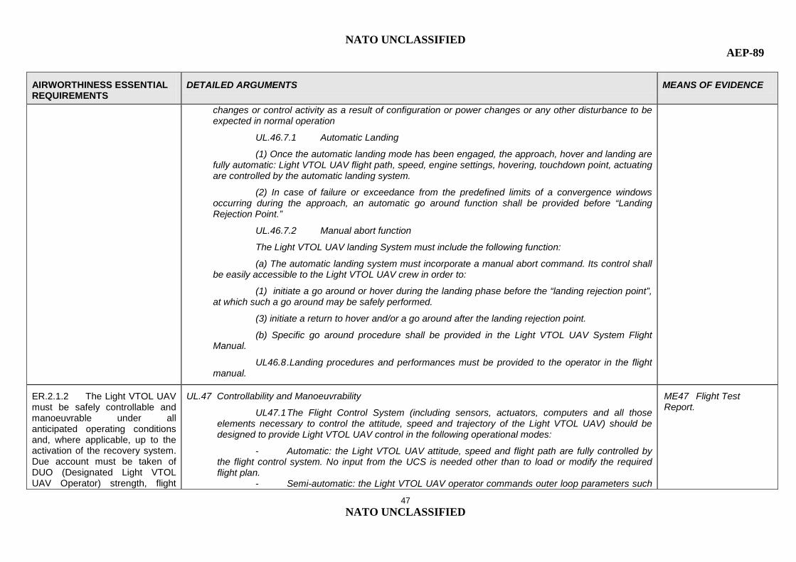
NATO UNCLASSIFIED AEP-89
47 NATO UNCLASSIFIED
AIRWORTHINESS ESSENTIAL REQUIREMENTS
DETAILED ARGUMENTS MEANS OF EVIDENCE
changes or control activity as a result of configuration or power changes or any other disturbance to be expected in normal operation
UL.46.7.1 Automatic Landing
(1) Once the automatic landing mode has been engaged, the approach, hover and landing are fully automatic: Light VTOL UAV flight path, speed, engine settings, hovering, touchdown point, actuating are controlled by the automatic landing system.
(2) In case of failure or exceedance from the predefined limits of a convergence windows occurring during the approach, an automatic go around function shall be provided before “Landing Rejection Point.”
UL.46.7.2 Manual abort function
The Light VTOL UAV landing System must include the following function:
(a) The automatic landing system must incorporate a manual abort command. Its control shall be easily accessible to the Light VTOL UAV crew in order to:
(1) initiate a go around or hover during the landing phase before the “landing rejection point”, at which such a go around may be safely performed.
(3) initiate a return to hover and/or a go around after the landing rejection point.
(b) Specific go around procedure shall be provided in the Light VTOL UAV System Flight Manual.
UL46.8 .Landing procedures and performances must be provided to the operator in the flight manual.
ER.2.1.2 The Light VTOL UAV must be safely controllable and manoeuvrable under all anticipated operating conditions and, where applicable, up to the activation of the recovery system. Due account must be taken of DUO (Designated Light VTOL UAV Operator) strength, flight
UL.47 Controllability and Manoeuvrability
UL47.1 The Flight Control System (including sensors, actuators, computers and all those elements necessary to control the attitude, speed and trajectory of the Light VTOL UAV) should be designed to provide Light VTOL UAV control in the following operational modes:
- Automatic: the Light VTOL UAV attitude, speed and flight path are fully controlled by the flight control system. No input from the UCS is needed other than to load or modify the required flight plan.
- Semi-automatic: the Light VTOL UAV operator commands outer loop parameters such
ME47 Flight Test Report.

NATO UNCLASSIFIED AEP-89
48 NATO UNCLASSIFIED
AIRWORTHINESS ESSENTIAL REQUIREMENTS
DETAILED ARGUMENTS MEANS OF EVIDENCE
deck environment, DUO workload and other human-factor considerations and of the phase of flight and its duration.
as altitude, heading and air speed. The flight control system operates the Light VTOL UAV controls to achieve the commanded outer loop parameter value.
- Manual direct piloting mode: the Light VTOL UAV operator directly commands Light VTOL UAV controls. This control mode may be limited to some flight phases (e.g. take off and landing) or emergency conditions, as agreed by the Certifying Authority.
UL47.2 There must be a clear unambiguous means in the UCS/UCB to indicate to the Light VTOL UAV operator the active mode of control of the FCS.
UL47.3 Controllability and manoeuvrability
a) The Light VTOL UAV must be safely controllable and manoeuvrable in all FCS operating modes and in manual direct piloting mode (where applicable), in the most severe operating conditions as per UL.0, during all flight phases including;
(1) During steady flight; and
(2) During any manoeuvre appropriate to the type, including-
(i) Take-off;
(ii) Climb;
(iii) Level flight;
(iv) Turning flight;
(v) Glide;
(vi) Landing (power-on and power-off); and
(vii) Recovery to power-on flight from a balked autorotative approach
(b) The margin of cyclic control must allow satisfactory roll and pitch control at VNE with-
(1) Critical weight;
(2) Critical centre of gravity;
(3) Critical vertical lifting element(s) rpm; and
(4) Power off and power-on.
c) A wind velocity determined by the applicant and approved by the Certfying Authority from all

NATO UNCLASSIFIED AEP-89
49 NATO UNCLASSIFIED
AIRWORTHINESS ESSENTIAL REQUIREMENTS
DETAILED ARGUMENTS MEANS OF EVIDENCE
azimuths, must be established in which the Light VTOL UAV can be operated without loss of control on or near the ground in any manoeuvre appropriate to the type, such as crosswind takeoffs, sideward flight and rearward flight:
(1) With altitude, from standard sea-level conditions to the maximum take-off and landing altitude capability of the Light VTOL UAV or a density altitude, determined by the applicant and approved by the regulator whichever is less with:
(i) Critical weight;
(ii) Critical centre of gravity; and
(iii) Critical rpm.
(iv) Altitude from standard sea level conditions to the maximum altitude for which landing and takeoff certification is sought.
(2) Not applicable
(d) The Light VTOL UAV, after complete engine failure, must be controllable over the range of speeds and altitudes for which certification is requested when such power failure occurs with maximum continuous power and critical weight. No corrective action time delay for any condition following power failure may be less than-
(1) For the cruise condition, one second (or approved duration by the regulator); and
(2) For any other condition, one second (or approved duration by the regulator).
(e) For Light VTOL UAV for which a VNE (power-off) is established under UL.49 compliance must be demonstrated with the following requirements with critical weight, critical centre of gravity, and critical rpm:
(1) The Light VTOL UAV must be safely slowed to VNE (power-off), after the last operating engine is made inoperative at power-on VNE;
(2) At a speed of 1.1 VNE (power-off), the margin of cyclic control must allow satisfactory roll and pitch control with power off.
UL47.4 The Light VTOL UAV flight mechanics behaviour when it encounters the gust as per UL5.3 must be characterized and potential limitations (taking due account of the design usage spectrum as per UL.0) established where applicable and documented in operating manuals.

NATO UNCLASSIFIED AEP-89
50 NATO UNCLASSIFIED
AIRWORTHINESS ESSENTIAL REQUIREMENTS
DETAILED ARGUMENTS MEANS OF EVIDENCE
UL.48 Trim
The Flight Control System (FCS) must trim the Light VTOL UAV in such a manner that a maximum of control remains and that dynamic characteristics and safety margins are not compromised.
ME48 Flight Test Report.
UL.49 Never-exceed speed
(a) The never-exceed speed, VNE, must be established so that it is:
(1) Not less than 74 km/h (40 knots) (CAS); and
(2) Not more than the lesser of:
(i) 0.9 times the maximum forward speeds established under UL.2.3;
(ii) 0.9 times the maximum speed shown under UL.8; or
(iii) 0.9 times the maximum speed substantiated for advancing blade tip mach number effects.
(b) VNE may vary with altitude, rpm, temperature, and weight if the system is able to automatically maintain the relevant limitation based on the appropriate influencing parameters.
(c) If autorotation capability is implemented, a stabilized power-off VNE denoted as VNE (power-off) may be established at a speed less than VNE established pursuant to sub-paragraph (a), if the following conditions are met:
(1) VNE (power-off) is not less than a speed midway between the power-on VNE and the speed used in meeting the requirements of:
(a) Climb: The steady rate of climb must be determined at maximum continuous power:
(i) At a speed for which certification is requested;
(ii) From sea level up to an altitude for which certification is requested;
(iii) At weights and temperatures for which certification is requested.
-
ME49

NATO UNCLASSIFIED AEP-89
51 NATO UNCLASSIFIED
AIRWORTHINESS ESSENTIAL REQUIREMENTS
DETAILED ARGUMENTS MEANS OF EVIDENCE
UL.50 Stability (see Annex H for additional guidance)
UL50.1 The Light VTOL UAV in all its operating modes, both augmented by the FCS and in manual direct piloting conditions (where applicable), including the effects of sensor and computational errors and delays, must be longitudinally, directionally and laterally stable in any condition normally encountered in service, at any combination of weight and centre of gravity for which certification is requested.
UL50.2 Transient response in all axes during transition between different flight conditions and FCS flight modes must be smooth, convergent, and exhibit damping characteristics with minimal overshoot of the intended flight path.
UL50.3 In addition to data obtained by computation or modelling, stability analysis must be supported by the results of relevant flight tests.
UL50.4 Stability also must be assessed in manual direct piloting conditions (where applicable), taking due account of data-link latencies.
UL50.5 Pilot (DUO) induced oscillation (PIO) tendencies must be safe, with particular consideration to manual direct piloting conditions flight characteristics (where applicable).
ME50 Model analysis and flight test.
UL.51 A qualitative evaluation of the DUO workload and degree of difficulty in all FCS operating modes including manual direct piloting (where applicable) and in all flight phases (e.g. launching strength) should be done in order to demonstrate that the probability of piloting errors is reduced to the minimum. Workloads in emergency conditions and in case of possible deconflicting manoeuvres should also be evaluated.
Note - Depending on the Light VTOL UAV design features complexity, the Certifying Authority may issue recommendations concerning DUO training syllabus as necessary.
ME51 Flight Test Report including workload assessment.
ER.2.1.3 It must be possible to make smooth transition(s) from one flight phase to another without requiring exceptional piloting skill, alertness, strength or workload under any probable
UL.52 It must be possible to make a smooth transition from one flight phase and/or condition to another (including turns and slips) without danger of exceeding the operating limitations of the Light VTOL UAVr, under any probable operating condition, (including, for multi-engine Light VTOL UAV, those conditions normally encountered in the sudden failure of any engine).
Where applicable, consideration must be given to the transition from launch phase and normal flight
ME52 Flight Test Report.

NATO UNCLASSIFIED AEP-89
52 NATO UNCLASSIFIED
AIRWORTHINESS ESSENTIAL REQUIREMENTS
DETAILED ARGUMENTS MEANS OF EVIDENCE
operating condition. condition, as well as the transition from normal flight condition to recovery phase.
ER.2.1.4 The Light VTOL UAV must have handling qualities that ensures the demands made on the DUO are not excessive taking into account the phase of flight and its duration.
N/A
[It concentrates on handling qualities effects on DUO controls; it is assumed that there is no artificial feedback on the controls in direct mode piloting condition.
In ER 2.1.2 due account has already been taken of DUO strength, flight deck environment, DUO workload and other human-factor considerations].
ER.2.1.5 Procedures for normal operations, failure and emergency conditions must be established.
UL.53 Emergency recovery capability
UL53.1 The Light VTOL UAV must integrate an emergency recovery capability that consists of:
- a flight termination system, procedure or function that aims to immediately end normal flight, or,
- an emergency recovery procedure that is implemented through Light VTOL UAV crew command or through the execution of a predefined course of events in order to mitigate the effects of critical failures with the intent of minimising the risk to third parties, or,
- any combination of the previous two options.
UL53.2 The emergency recovery capability must function as desired over the whole flight envelope under the most adverse combination of environmental conditions.
UL53.3 The emergency recovery capability must be safeguarded from interference leading to inadvertent operation.
ME53 Technical description
UL.54 Conflict Avoidance Manoeuvres
Possible conflict avoidance manoeuvres should be investigated according to the Light VTOL UAV manoeuvrability and identified in order to minimize the risk of in-flight collision.
ME54 Flight Test Report

NATO UNCLASSIFIED AEP-89
53 NATO UNCLASSIFIED
AIRWORTHINESS ESSENTIAL REQUIREMENTS
DETAILED ARGUMENTS MEANS OF EVIDENCE
UL.55 Engine shut down procedure
In the event of an engine failure that causes loss of thrust, an appropriate procedure must be defined and provided in the flight manual; the following apply.
UL55.1 The Light VTOL UAV must be designed to retain sufficient control and manoeuvrability until it has reached a forced landing area.
UL55.2 The emergency electrical power must be designed in such a way that its reliability and duration are compatible with UL55.1. The time period needed to perform a glide from maximum certificated altitude to sea level (ISA conditions) and reach a forced landing area includes the time needed for the Light VTOL UAV crew to recognise the failure and to take appropriate action, if required.
UL55.3 The engine shut down procedure must be analysed considering the existence of the emergency recovery capability specified in UL.53.
ME55 Technical description
UL.56 The Flight Manual provided to the Light VTOL UAV operator must clearly and unambiguously define all the
- operating procedures, and - operating limitations, and - performance information,
for
- normal operations, and - failure conditions and emergency conditions. Where the emergency recovery capability includes a
pre-programmed course of action to reach a predefined site where it can be reasonably expected that fatality will not occur, the dimensions of such areas must be stated in the Light VTOL UAV Flight Manual,
- possible conflict avoidance manoeuvres.
ME56 Flight Manual
ER.2.1.6 Warnings, or other deterrents intended to prevent exceeding the normal flight envelope, must be provided, as appropriate to type.
UL.57 The Light VTOL UAV should be designed so that:
UL57.1 in automatic or semi-automatic operating modes, the Light VTOL UAV should remain within a flight envelope sufficiently protected by the FCS in order to avoid any unsafe condition (see UL.58);
UL57.2 in manual direct piloting mode (where applicable), the operator should be alerted with
ME57 Technical description of Light VTOL UAV flight envelope protection design features

NATO UNCLASSIFIED AEP-89
54 NATO UNCLASSIFIED
AIRWORTHINESS ESSENTIAL REQUIREMENTS
DETAILED ARGUMENTS MEANS OF EVIDENCE
sufficient margin when approaching any unsafe condition.
UL.58 Flight Envelope Protection (where applicable)
UL58.1 Flight envelope protection must be implemented in the flight control system as follows.
- Characteristics of each envelope protection feature must be smooth, appropriate to the phase of flight and type of manoeuvre.
- Limit values of protected flight parameters must be compatible with:
- Light VTOL UAV structural limits,
- vertical lift components rotational speed limits, (e.g. rotorblades, fan blades, etc.)
- required safe and controllable manoeuvring of the Light VTOL UAV,
- margin to catastrophic failure conditions.
-vertical lift components stall limits,
- engine and transmission torque limits.
- The Light VTOL UAV must respond to intentional dynamic manoeuvring within a suitable range of parameter limit.
- Dynamic characteristics such as damping and overshoot must also be appropriate for the manoeuvre and limit parameter concerned.
- Characteristics of the flight control system must not result in residual oscillations in commanded output due to combinations of flight envelope protection limits and any other flight control internal limit.
UL58.2 When simultaneous envelope protection limits are engaged, adverse coupling or adverse priority must not result.
UL58.3 The Applicant must define clearly the borders and prioritization within the control system of the flight envelope protection maintained by the flight control system.
ME58 Technical description of Light VTOL UAV flight envelope protection design features + model simulation analysis + flight test report
ER.2.1.7 The characteristics of the Light VTOL UAV and its systems must allow a safe return
UL.59 A safe return from the extremes of the flight envelope that may be encountered in all operating modes must be demonstrated by simulation and it should be demonstrated in flight.
ME59 Flight Test Report.

NATO UNCLASSIFIED AEP-89
55 NATO UNCLASSIFIED
AIRWORTHINESS ESSENTIAL REQUIREMENTS
DETAILED ARGUMENTS MEANS OF EVIDENCE
from extremes of the flight envelope that may be encountered.
ER.2.2 The operating limitations and other information necessary for safe operation must be made available to the crew members.
The information needed for the safe conduct of the flight and information concerning unsafe conditions are displayed in the UCS/UCB as per UL.32 and UL.33.
UL.60 The Flight Manual provided to the Light VTOL UAV operator must clearly and unambiguously define all the operating limitations and other information necessary for safe operation (see also UL.56).
ME60 Flight Manual
ER.2.3 System operations must be protected from hazards resulting from adverse external and internal conditions, including environmental conditions.
See UL.35 and UL.36.
In particular, environmental tests are required by UL35.2.
Consideration to bird-strike is given in UL.13.
ER.2.3.1 In particular, account must be taken of the exposure to phenomena such as, but not limited to, adverse weather, lightning, bird strike, high frequency radiated fields, ozone, etc., expected to occur during system operation.
ER.2.3.2 Where applicable, cabin compartments must provide passengers with suitable transport conditions and adequate protection from any expected hazard arising in flight operations or resulting in emergency situations, including fire, smoke, toxic gases and rapid decompression hazards.
N/A
For the UCS/UCB see also UL.27 and UL.30.

NATO UNCLASSIFIED AEP-89
56 NATO UNCLASSIFIED
AIRWORTHINESS ESSENTIAL REQUIREMENTS
DETAILED ARGUMENTS MEANS OF EVIDENCE
Provisions must be made to give occupants every reasonable chance of avoiding serious injury and quickly evacuating the aircraft and to protect them from the effect of the deceleration forces in the event of an emergency landing on land or water. Clear and unambiguous signs or announcements must be provided, as necessary, to instruct occupants in appropriate safe behaviour and the location and correct use of safety equipment. Required safety equipment must be readily accessible.
ER.2.3.3 Crew compartments must be arranged in order to facilitate flight operations, including means providing situational awareness, and management of any expected situation and emergencies. The environment of crew compartments must not jeopardise the crew's ability to perform their tasks and its design must be such as to avoid interference during operation and misuse of the controls.
See UL.27, UL.32, UL.33.
In particular human-machine interface aspects are covered by UL27.3.

NATO UNCLASSIFIED AEP-89
57 NATO UNCLASSIFIED
AIRWORTHINESS ESSENTIAL REQUIREMENTS
DETAILED ARGUMENTS MEANS OF EVIDENCE
ER.3 Organisations
(It includes natural persons undertaking design, manufacture or maintenance)
ER.3.1 Organisations involved in design (including flight test), production (manufacture) or maintenance activities must satisfy the following conditions:
ER.3.1.1 The organisation must have all the means necessary for the scope of work. These means comprise, but are not limited to the following: facilities, personnel, equipment, tools and material, documentation of tasks, responsibilities and procedures, access to relevant data and record-keeping.
UL.61 The Applicant should ensure certification as per AS/EN 9100 for undertaking Light VTOL UAV design and production activities and the documented statement of the quality policy should explicitly include system safety as one of the main objectives: this should give a minimum confidence that safety management is implemented and that safety-related work is undertaken by competent individuals, in adequate facilities, with adequate tools, material, procedures and data.
ME61 Approved AS/EN 9100 Certificate or equivalent.
ER.3.1.2 The organisation must implement and maintain a management system to ensure compliance with these essential requirements for airworthiness, and aim for continuous improvement of this system.
UL.62 The Applicant must ensure implementation, documentation, operation and maintenance of an auditable Safety Management System.
Safety must be considered from the earliest stage in a programme and used to influence all activities from the concept of requirements definition, the development phase, production, operation, etc., until disposal.
Safety management should be integrated into a Systems Engineering approach that gives due consideration to safety alongside related issues.
The Applicant must submit to the Certifying Authority a Safety Management Plan which details the specific actions and arrangements required to operate the Safety Management System and define safety milestones for the project. It must provide the link between safety requirements and general
ME62 The minimum evidence to comply with this requirement is a Safety Management Plan, which is a significant document that provides a basis on which to achieve trust in the effectiveness of the Safety Management System.

NATO UNCLASSIFIED AEP-89
58 NATO UNCLASSIFIED
AIRWORTHINESS ESSENTIAL REQUIREMENTS
DETAILED ARGUMENTS MEANS OF EVIDENCE
management processes for the project, to ensure that safety is achieved and maintained for the complete Light VTOL UAV life cycle.
The Certifying Authority may audit the Safety Management System at its discretion.
Guidelines on information to be included in the Safety Management Plan are provided in Annex I.
UL.63 The aim for continuous improvement must be verified when assessing the Company management system. Normally it is covered under AS/EN 9100. Additional confidence may be obtained by complying with ISO 9004 [present title: Quality Management Systems – Guidelines for Performance Improvement] [future title: Managing for sustainable success – A quality management approach].
ME63 Approved AS/EN 9100 certificate + ISO 9004 or equivalent
ER.3.1.3 The organisation must establish arrangements with other relevant organisations, as necessary, to ensure continuing compliance with these essential requirements for airworthiness.
UL.64 The organisation must establish an interface with other relevant organisations, as necessary, to ensure continuing compliance with these essential requirements for airworthiness.
ME64 The Safety Management Plan (see Annex I).
ER.3.1.4 The organisation must establish an occurrence reporting and/or handling system, which must be used by the management system under point ER.3.1.2 and the arrangements under point ER.3.1.3, in order to contribute to the aim of continuous improvement of the safety of systems (“continuing airworthiness of the type design”).
UL.65 The organisation must establish an occurrence reporting and/or handling system, which must be used by the management system under point ER.3.1.2 and the arrangements under point ER.3.1.3, in order to contribute to the aim of continuous improvement of the safety of systems (“continuing airworthiness of the type design”).
ME65 The Safety Management Plan (see Annex I)
ER.3.2 In the case of maintenance training organisations, the conditions under points 3.3.1.3 and 3.3.1.4 do not apply.
N/A

NATO UNCLASSIFIED AEP-89
59 NATO UNCLASSIFIED
AIRWORTHINESS ESSENTIAL REQUIREMENTS
DETAILED ARGUMENTS MEANS OF EVIDENCE
Light VTOL UAV HANDOVER
(where applicable)
UL.66 Where the Light VTOL UAV is designed for Light VTOL UAV hand over between two UCS/UCB:
UL66.1 The in-control UCS/UCB must be clearly identified to all Light VTOL UAV operators.
UL66.2 Positive control must be maintained during handover.
UL66.3 The command and control functions that are transferred during handover must be approved by the Certifying Authority and defined in the Light VTOL UAV Flight Manual.
UL66.4 Handover between two UCS/UCB must not lead to unsafe conditions.
UL66.5 The in-control UCS/UCB must have the required functionality to accommodate emergency situations
ME66 Technical description + Flight test report
UL.67 Where a UCS/UCB is designed to command and control multiple Light VTOL UAV:
UL67.1 The minimum Light VTOL UAV crew must be established so that it is sufficient for safe operation of each Light VTOL UAV and emergency condition.
UL67.2 The Light VTOL UAV data must be displayed in the UCS/UCB in a manner that prevents confusion and inadvertent operation.
UL67.3 The Light VTOL UAV controls must be available to the Light VTOL UAV crew for each Light VTOL UAV of which it has command and control, in a manner that prevents confusion and inadvertent operation.
UL67.4 All indicators and warnings must be available to the Light VTOL UAV crew for each Light VTOL UAV, in a manner that prevents confusion and inadvertent operation
ME67 Technical description + Flight test report
UL.68 Where the UCS has more than one workstation designed for controlling the Light VTOL UAV:
UL68.1 The in-control workstation must be clearly identified to all Light VTOL UAV crew members.
UL68.2 Positive control must be maintained during handover.
UL68.3 The command and control functions that are transferred during handover must be approved by the Certifying Authority and defined in the Light VTOL UAV Flight Manual.
ME68 Technical description + Flight test report
NATO UNCLASSIFIED AEP-89
60 NATO UNCLASSIFIED
AIRWORTHINESS ESSENTIAL REQUIREMENTS
DETAILED ARGUMENTS MEANS OF EVIDENCE
UL68.4 Handover within the same Light VTOL UAV UCS must not lead to unsafe conditions.
UL68.5 The in-control workstation must have the required functionality to accommodate emergency situations.
UL.69 Where the UCS/UCB is designed to monitor multiple Light VTOL UAV, there must be a means to clearly indicate to the Light VTOL UAV crew the Light VTOL UAV over which it has command and control.
ME69 Technical description + Flight test report

NATO UNCLASSIFIED AEP-89
61 NATO UNCLASSIFIED
INTENTIONALLY BLANK

NATO UNCLASSIFIED
A-1 NATO UNCLASSIFIED
ANNEX A TO AEP-83
A 1 Acronyms and abbreviations A.2. Terms and definitions
A.1. Acronyms and Abbreviations. The following acronyms are used for the purpose of this agreement.
ARP Aerospace Recommended Practices BIT Built in Test CG Centre of Gravity DAL Development Assurance Level DAL Development Assurance Level DDP Declaration of Design and Performance DUO Designated UA Operator EMC Electromagnetic Compatibility EME Electromagnetic Emission EMI Electromagnetic Interference EMRADHAZ Hazards of Electromagnetic Radiation to Personnel EMV Electromagnetic Vulnerability FCS Flight Control System GAT General Air Traffic GPS Global Positioning System h Hour HIGE Hover in Ground Effect HIRF High Intensity Radiated Fields HOGE Hover out of Ground Effect HW Hot Wet LOS Line of Sight MTOW Maximum Take Off Weight NATO North Atlantic Treaty Organization OAT Operational Air Traffic PII Pilot Induced Instabilities PLD Programmable Logic Device PSE Primary Structural Elements RPM Revolutions per Minute RPM Revolutions per Minute RTD Room Temperature Dry SSA System Safety Assessment STANAG (NATO) Standard Agreement STANREC NATO) Standard Recommendation UA Unmanned Aircraft UAS Unmanned Aircraft System.

NATO UNCLASSIFIED AEP-89
A-2 NATO UNCLASSIFIED
UCB / UCS UA Control Box / UA Control Station USAR UAV Systems Airworthiness Requirements VH Max speed in level flight with max continuous power VNE Never Exceed Speed VNO maximum structural cruising speed
A.2. Terms and Definitions The following terms and definitions are used for the purpose of this agreement.
Applicant The entity applying for the Type Certificate Automatic The execution of a predefined process or event that requires UAV
crew initiation Autorotation Light VTOL UAV flight condition in which the vertical lifting element(s)
is driven entirely by action of the air when the Light VTOL UAV is in motion.
Catastrophic Failure conditions that result in worst case credible outcomes of at least uncontrolled flight (including flight outside of pre-planned or contingency flight profiles/areas) and/or uncontrolled crash, which can potentially result in a fatality. Or Failure conditions which could potentially result in a fatality to Light VTOL UAV crew or ground staff.
Data link
Wireless communication channel between one or more UCS and one or more Light VTOL UAV, or between multiple Light VTOL UAV. Its utility may include but is not limited to exchange of command & control or payload data. A data link may consist of:
• Uplink - Transmittal of Light VTOL UAV crew commands from the UCS to the Light VTOL UAV.
• Downlink - Transmittal of Light VTOL UAV status data from the Light VTOL UAV to the UCS.
Designated UAV Operator DUO
Operator tasked with overall responsibility for operation and safety of the Light VTOL UAV system. Equivalent to the pilot in command of a manned aircraft.
Design usage spectrum The Applicant uses this information as the basis for assumptions underpinning fatigue and damage tolerance and associated individual Light VTOL UAV tracking. The design usage spectrum is therefore necessary for producing and maintaining the Fatigue Type Record or equivalent document. The applicant also uses the design usage spectrum to identify any gross deviation between design assumptions and Service usage. The design usage spectrum is descriptive, rather than prescriptive. The design usage spectrum contains a breakdown of the typical Sortie Profiles Codes (SPCs) or any equivalent for the Light VTOL UAV type in each of its roles and at each typical operating location. SPCs or any equivalent are expressed in terms of height, time, speed, mass and configuration data, which are derived from recorded sortie information. The initial issue of the design usage spectrum should be produced as early as possible in the project life cycle and should be reviewed and updated throughout the life of type.
Effective maximum range
Measure of data link coverage over a horizontal distance that is a function of frequency, availability, bit error rate, climate area and altitude.

NATO UNCLASSIFIED AEP-89
A-3 NATO UNCLASSIFIED
Electromagnetic Compatibility EMC
Ability of equipment or a system to function in its electromagnetic environment without causing intolerable electromagnetic disturbances to anything in that environment.
Electromagnetic Environment EME
The totality of electromagnetic phenomena existing at a given location.
Electromagnetic Interference EMI
Any electromagnetic disturbance, whether intentional or not, which interrupts, obstructs, or otherwise degrades or limits the effective performance of electronic or electrical equipment.
Emergency recovery capability
Procedure that is implemented by Light VTOL UAV crew command or by means of autonomous design in order to mitigate the effects of critical failures with the intent of minimizing the risk to third parties. This may include automatic pre-programmed course of action to reach a predefined and unpopulated forced landing or recovery area.
Emergency landing
Exceptional landing condition that could lead to a severe level constraint on the structure.
Extremely remote Occurrence between 10-5 and 10-6 per flight hour. Failure conditions
A condition having an effect on either the Light VTOL UAV or third parties, or both, either direct or consequential, which is caused or contributed to by one or more failures or errors considering flight phase and relevant adverse operational or environmental conditions or external events.
Fire-resistant
With respect to materials, components and equipment, means the capability to withstand the application of heat by a flame, as defined for ‘Fireproof’, for a period of 5 minutes without any failure that would create a hazard to the Light VTOL UAV. For materials this may be considered to be equivalent to the capability to withstand a fire at least as well as aluminium alloy in dimensions appropriate for the purposes for which they are used.
Flight control system FCS
The flight control system comprises sensors, actuators, computers and all those elements of the Light VTOL UAV System, necessary to control the attitude, speed and flight path of the Light VTOL UAV. The flight control system can be divided into 2 parts:
Flight control computer - A programmable electronic system that operates the flight controls in order to carry out the intended inputs.
Flight controls - Sensors, actuators and all those elements of the Light VTOL UAV System (except the flight control computer), necessary to control the attitude, speed and flight path of the Light VTOL UAV.
Flight load factor Ratio of the aerodynamic force component (acting normal to the assumed longitudinal axis of the Light VTOL UAV) to the weight of the Light VTOL UAV. A positive flight load factor is one in which the aerodynamic force acts upward, with respect to the Light VTOL UAV.
Flight Envelope Protection
System that prevents the Light VTOL UAV from exceeding its designed operating limits.
Flight termination system:
System to immediately terminate flight.
Forced landing Condition resulting from one or a combination of failure conditions Ground staff
Qualified personnel necessary for ground operations (such as supplying the Light VTOL UAV with fuel and maintenance) as stated in the Light VTOL UAV System Flight Manual or in the Light VTOL UAV Maintenance Manual.

NATO UNCLASSIFIED AEP-89
A-4 NATO UNCLASSIFIED
Hand over
Operation that consists in performing a Light VTOL UAV command and control transfer from one UCS to another one or from one workstation to another one in the same UCS.
Hazardous
Failure conditions that either by themselves or in conjunction with increased crew workload, result in a worst credible outcome of a controlled-trajectory termination or forced landing potentially leading to the loss of the Light VTOL UAV where it can be reasonably expected that a fatality will not occur; Or, failure conditions which could potentially result in serious injury to Light VTOL UAV crew or ground staff.
Landing
The process in which an aircraft is brought from a safe flight condition to a standstill on the intended landing surface (ground, sea surface, etc).
Landing Rejection point:
Point in the landing trajectory beyond which the Light VTOL UAV has automatically determined to continue to its touchdown. Beyond this point, the Light VTOL UAV will only abort the landing and continue to a safe and stabilized airborne state if manually aborted by the Light VTOL UAV crew.
Line of Sight
Visually unobstructed straight line through space between the transmitter and receiver
Major
Description of a failure condition that either by itself or in conjunction with increased crew workload, result, in a worst credible outcome of an emergency landing of the Light VTOL UAV on a predefined site where it can be reasonably expected that a serious injury will not occur
Masking
Blockage of data link due to fuselage blockage or unfavourable Light VTOL UAV attitude
Minor
Description of a failure condition that does not significantly reduce Light VTOL UAV safety and involve Light VTOL UAV crew actions that are well within their capabilities
Must
Indicates a mandatory requirement (see also “shall”).
Payload
Device or equipment carried by the Light VTOL UAV which performs the mission assigned. The payload comprises all elements of the air vehicle that are not necessary for flight but are carried for the purpose of fulfilling specific mission objectives.
Probable
Occurrence between 10-3 and 10-4 per flight hour.
Remote In the system safety context, occurrence between 10-4 and 10-5 per flight hour.
Safety trace Area associated with the take-off/launch and landing/recovery phases of a Light VTOL UAV in which an otherwise unacceptable risk is mitigated by clearing that area.
Secondary flight control All flight controls other than primary flight controls such as wheel brakes, vertical lifting element(s) brakes controls.
Shall Indicates a mandatory requirement (see also “must”). Should Indicates a preferred, but not mandatory, method of accomplishment. Take-off Process by which an aircraft leaves the surface and attains controlled
flight (includes launch via catapult or rocket assistance). Takeoff Rejection Point Point in the takeoff trajectory before which a rejected takeoff results in
the Light VTOL UAV: either automatically returning to a touchdown (if already airborne), or holding on the pad (if not already airborne); and after which, the Light VTOL UAV will automatically continue to a safe and stabilized airborne state.

NATO UNCLASSIFIED AEP-89
A-5 NATO UNCLASSIFIED
Light VTOL UAV Control Box / Light VTOL UAV Control Station
A facility or device from which the Light VTOL UAV is controlled and/or monitored for all phases of flight.
Unmanned Aircraft System
A UAS comprises individual UAS elements consisting of the UA, the UA control station and any other UAS elements necessary to enable flight, such as a command and control data link, communication system, and take-off and landing element. There may be multiple UA, UCS, or take off and landing elements within a UAS. Includes the UA, modular mission payloads, data links, launch and recovery equipment, mission planning and control stations, data exploitation stations and logistic support.
Unmanned Aerial Vehicle UAV
Aircraft which is designed to operate with no human pilot on board and which does not carry personnel. Moreover a UAV is:
• capable of sustained flight by aerodynamic means, • remotely piloted or automatically flies a pre-programmed flight profile, • reusable, • not classified as a guided weapon or similar one shot device designed for the delivery of munitions.
UCS flight control Flight controls used by the UAV crew in the UCS to operate the UAV in the semi-automatic mode of control.
Unsafe
Condition or situation that is likely to cause a Hazardous or more serious event
Workload
Amount of work assigned to or expected from a person in a specified time
Workstation
Computer interface between an individual Light VTOL UAV crew member and the Light VTOL UAV to perform the functions of mission planning, flight control and monitoring and for display and evaluation of the downloaded image and data (where applicable)
Vertical Take Off and Landing VTOL
An aircraft that uses powered lift to ascend or descend vertically or near vertically and does not require forward flight to generate continuous lift by a fixed non moving lifting surface to remain airborne. Light VTOL aircraft may exhibit forward, rearward and side to side flight or hover in place.

NATO UNCLASSIFIED
C-1 NATO UNCLASSIFIED
ANNEX B TO AEP-83
LANDING GEAR
UL.GL.1 Shock absorption tests The landing inertia load factor and the reserve energy absorption capacity of the landing gear must be substantiated by the tests prescribed in UL.GL.2 and UL.GL.3, respectively or by analysis. These tests must be conducted on the complete rotorcraft or on undercarriage units in their proper relation." UL.GL.2 Limit drop test The limit drop test must be conducted as follows: (a) The drop height must be 0.20 m (8 inches) from the lowest point of the landing gear to the ground; or (b) If considered, the rotor lift specified in UL.6.2 (a) must be introduced into the drop test by appropriate energy absorbing devices or by the use of an effective mass. (c) Each landing gear unit must be tested in the attitude simulating the landing condition that is most critical from the standpoint of the energy to be absorbed by it. (d) When an effective mass is used in showing compliance with sub-paragraph (b) the following formula may be used instead of more rational computations: where:
We = the effective weight to be used in the drop test. W=WM for main gear units, equal to the static reaction on the particular unit with the rotorcraft UAV in the most critical attitude. A rational method may be used in computing a main gear static reaction, taking into consideration the moment arm between the main wheel reaction and the rotorcraft centre of gravity. W=WN for nose gear units, equal to the vertical component of the static reaction that would exist at the nose wheel, assuming that the mass of the rotorcraft acts at the centre of gravity and exerts a force of 1.0 g downward and 0.25 g forward. W=WT for tail wheel units equal to whichever of the following is critical: (1) The static weight on the tail wheel with the rotorcraft UAV resting on all wheels; or (2) The vertical component of the ground reaction that would occur at the tail wheel, assuming that the mass of the rotorcraft UAV acts at the centre of gravity and exerts a force of 1 g downward with the rotorcraft in the maximum nose-up attitude considered in the nose-up landing conditions. h = specified free drop height. L = ratio of assumed rotor lift to the rotorcraft weight. d = deflection under impact of the tyre (at the proper inflation pressure) plus the vertical component of the axle travel relative to the drop mass. n = limit inertia load factor. nj = the load factor developed, during impact, on the mass used in the drop test (i.e., the acceleration dv/dt in g recorded in the drop test plus 1.0)." UL.GL.3 Reserve energy absorption drop tests The reserve energy absorption drop test must be conducted as follows: (a) The drop height must be 1.5 times that specified in UL.GL.2(a).

NATO UNCLASSIFIED AEP-89
C-2 NATO UNCLASSIFIED
(b) Rotor lift, where considered in a manner similar to that prescribed in UL.GL.2(b), may not exceed 1.5 times the lift allowed under that paragraph. (c) The landing gear must withstand this test without collapsing. Collapse of the landing gear occurs when a member of the nose, tail, or main gear will not support the rotorcraft in the proper attitude or allows the rotorcraft UAV structure, other than the landing gear and external accessories, to impact the landing surface. " UL.GL.4 Skis The maximum limit load rating of each ski must equal or exceed the maximum limit load determined under the applicable ground load requirements of this code." UL.GL.5 Main float buoyancy (a) For main floats, the buoyancy necessary to support the maximum weight of the rotorcraft in fresh water must be exceeded by- (1) 50 %, for single floats; and (2) 60 %, for multiple floats. (b) Each main float must have enough watertight compartments so that, with any single main float compartment flooded, the main floats will provide a margin of positive stability great enough to minimize the probability of capsizing." UL.GL.6 Main float design (a) Bag floats. Each bag float must be designed to withstand- (1) The maximum pressure differential that might be developed at the maximum altitude for which certification with that float is requested; and (2) The vertical loads prescribed in CS VLR.521(a), distributed along the length of the bag over three-quarters of its projected area. (b) Rigid floats. Each rigid float must be able to withstand the vertical, horizontal, and side loads prescribed in CS VLR.521. These loads may be distributed along the length of the float." UL.GL. 7 Hulls For each rotorcraft UAV, with a hull and auxiliary floats, that is to be approved for both taking off from and landing on water, the hull and auxiliary floats must have enough watertight compartments so that, with any single compartment flooded, the buoyancy of the hull and auxiliary floats (and wheel tires if used) provides a margin of positive stability great enough to minimize the probability of capsizing."
ANNEX C TO AEP-83
SPARK AND COMPRESSION IGNITION RECIPROCATING ENGINES
GENERAL
UL.RE.1 Instruction manual
An instruction manual containing the necessary information essential for installing, operating, servicing and maintaining the engine must be provided.
UL.RE.2 Engine ratings and operating limitations Engine ratings and operating limitations are to be established and based on the operating conditions demonstrated during the bench tests prescribed in this Annex. They include power ratings and operational limitations relating to speeds,

NATO UNCLASSIFIED AEP-89
C-3 NATO UNCLASSIFIED
temperatures, pressures, fuels and oils which are necessary for the safe operation of the engine.
UL.RE.3 Selection of engine power ratings Each selected rating must be for the lowest power that all engines of the same type may be expected to produce under the conditions to determine that rating.
ENGINE CONTROL SYSTEM
UL.RE.4 It must be substantiated by tests, analysis or a combination thereof that the Engine Control System performs the intended functions in all its control modes and in accordance with the design usage spectrum as per UL.0: - without exceeding operating limits within the flight envelope, - allowing adequate modulation of power/thrust, - without creating excessive power/thrust oscillations, - with safe transition between different control modes, - without surge and stall of the engine.
DESIGN AND CONSTRUCTION
UL.RE.5 Materials
The suitability and durability of materials used in the engine must (a) be established on the basis of experience or tests; (b) conform to approved specifications that ensure their having the strength and
other properties assumed in the design data; (c) demonstrate that measures are taken to ensure protection from corrosion and
deterioration. UL.RE.6 Strength
The maximum stresses developed in the Engine must not exceed values conforming to those established by satisfactory practice for the material involved, due account being taken of the particular form of construction and the most severe operating conditions.
UL.RE.7 Fire prevention
(a) The design and construction of the engine and the materials used must minimise the probability of the occurrence and spread of fire because of structural failure, overheating or other causes.
(b) Each tank, external line or fitting that conveys flammable fluids must be at least fire resistant. Components must be shielded or located to safeguard against the ignition of leaking flammable fluid.
UL.RE.8 Electrical bonding.
Any components, modules, equipment and accessories that are susceptible to or are potential sources of static discharges or currents from electrical faults, must be designed and constructed so as to be grounded to the main Engine earth, as necessary to minimise the accumulation of electro-static or electrical charge that would cause: - Injury from electrical shock,

NATO UNCLASSIFIED AEP-89
C-4 NATO UNCLASSIFIED
- Unintentional ignition in areas where flammable fluids or vapours could be present, - Unacceptable interference with electrical or electronic equipment.
UL.RE.9 Durability
Engine design and construction must minimise the probability of occurrence of an unsafe condition of the engine between overhauls (a) The effects of cyclic loading, environmental and operational degradation must
not reduce the integrity of the engine below acceptable levels. (b) The effects of likely subsequent part failures must not reduce the integrity of
the engine below acceptable levels. UL.RE.10 Engine cooling
Engine design and construction must provide the necessary cooling under conditions in which the UA is expected to operate.
UL.RE.11 Engine mounting attachments and structure
(a) The maximum allowable loads for engine mounting attachments and related structure must be specified, taking account of the flight and ground loads calculated from the UA design usage spectrum (UL.0.).
(b) The engine mounting attachments and related structure must be able to withstand the specified loads without failure, malfunction or permanent deformation.
UL.RE.12 Accessory attachment
Each accessory drive and mounting attachment must be designed and constructed so that the engine will operate properly with the accessories attached. The design of the engine must allow the examination, adjustment or removal of each essential engine accessory.
UL.RE.13 Vibration
The engine must be designed and constructed to function throughout its normal operating range of crankshaft rotational speeds and engine powers without inducing excessive stress in any of the engine parts because of vibration and without imparting excessive vibration forces to the structure of the UA.
UL.RE.14 Fuel and induction system
(a) The fuel system of the engine must be designed and constructed to supply the appropriate mixture of fuel to the combustion chambers throughout the complete operating range of the engine under all starting, flight and atmospheric conditions.
(b) The intake passages of the engine through which air, or fuel in combination with air, passes must be designed and constructed to minimise ice accretion and vapour condensation in those passages. The engine must be designed and constructed to permit the use of a means for ice prevention.
(c) Filters, strainers or other equivalent means must be provided to protect the fuel system from malfunction due to contaminants. These devices must have the capacity to accommodate any likely quantity of contaminants, including water, in relation to recommended servicing intervals and, if provided, the blockage or by-pass indication system.

NATO UNCLASSIFIED AEP-89
C-5 NATO UNCLASSIFIED
The Applicant must show (e.g. within the endurance test prescribed in UL.RE.22 (a)) that foreign particles passing through the prescribed filtering means will not critically impair engine fuel system functioning. Any main fuel filter or strainer having a significant function for the control of the power must have a means to permit indication to the DUO of impending blockage of the filter or strainer and all necessary instructions must be provided. If a by-pass means is provided on any filter or strainer, it must be demonstrated that open by-pass operation is safe.
(d) Each passage in the induction system that conducts a mixture of fuel and air, and in which fuel may accumulate, must be self-draining to prevent a liquid lock in the combustion chambers. This applies to all attitudes that the Applicant establishes as those the engine can have when the UA in which it is installed is in the static ground attitude.
UL.RE.15 Oil system (four-stroke engines only)
(a) The oil system of the engine must be designed and constructed so that it will function properly in all attitudes and atmospheric conditions in which the UA is expected to operate. In wet-sump engines this requirement must be met when the engine contains only the minimum oil quantity, the minimum quantity being not more than half the maximum quantity. In particular the oil breather (vent) must be resistant to blockage caused by icing.
(b) The oil system of the engine must be designed and constructed to allow installing a means of cooling the lubricant.
(c) The crankcase must be vented to preclude leakage of oil from excessive pressure in the crankcase.
(d) All parts of the oil system that are not inherently capable of accepting contaminants likely to be present in the oil or otherwise introduced into the oil system must be protected by suitable filter(s) or strainer(s). These must provide a degree of filtration sufficient to preclude damage to the engine and engine equipment and have adequate capacity to accommodate contaminants in relation to the specified servicing intervals. If the most critical main oil filter does not incorporate a by-pass, then it must have provision for appropriate indication to the DUO of impending blockage and all necessary instructions must be provided. If a by-pass means is provided on any filter or strainer, it must be demonstrated that open by-pass operation is safe. Indication of by-pass operation must be provided to permit appropriate maintenance action to be initiated.
(e) Each oil tank must: - have, or have provision for, an oil quantity indicator; - have an expansion space of an adequate size which must be impossible
to inadvertently fill. (f) Each brand and type of oil to be approved, and the associated limitations,
must be declared and substantiated.
UL.RE.16 Electromagnetic Compatibility The reciprocating engine spark ignition system and the other UAS components (e.g. data links, communication) must be electromagnetically compatible.

NATO UNCLASSIFIED AEP-89
C-6 NATO UNCLASSIFIED
UL.RE.17 All engine components must be resistant to humidity (applicable standards
that should be used as a reference to tailor a humidity test are RTCA-DO-160D or MIL-STD-810).
UL.RE.18 A failure analysis of the engine and its installation, including the control
system, must be made to establish that the engine does not introduce unacceptable hazards as per the UAS Hazard Reference System.
BENCH TESTS
UL.RE.19 Vibration test
Except where the engine is of a type of construction known not to be prone to hazardous vibration, the engine must undergo a vibration survey to establish crankshaft torsional and bending characteristics over a range of rotational speeds from idling to 110% of the maximum continuous speed or 103% of the maximum desired take-off speed, whichever is the greater. The survey must be conducted with a representative vertical lifting element (the vertical lifting element should be so chosen that the prescribed maximum rotational speed is obtained at full throttle or at the desired maximum permissible manifold pressure, whichever is appropriate). No hazardous condition may be present.
UL.RE.20 Calibration test
Each engine must be subjected to the calibration tests necessary to establish its power characteristics and the conditions for the endurance test specified in UL.RE.22 (a) to (c). The results of the power characteristics calibration tests form the basis for establishing the characteristics of the engine over its entire operating range of crankshaft rotational speeds, manifold pressures, and fuel/air mixture settings. Power ratings are based on standard atmospheric conditions at sea-level.
UL.RE.21 Detonation test (spark ignition only)
The engine must be tested to establish that it can function without detonation throughout the range of intended conditions of operation.
UL.RE.22 Endurance test
(a) The engine must be subjected to an endurance test (with a representative vertical lifting element) that includes a total of 50 hours of operation and consists of the cycles specified in UL.RE.22(c).
(b) Additional endurance testing at particular rotational speed(s) may be required depending on the results of the tests prescribed in UL.RE.19, to establish the ability of the engine to operate without fatigue failure.
(c) Each cycle must be conducted as follows:

NATO UNCLASSIFIED AEP-89
C-7 NATO UNCLASSIFIED
(d) During or following the endurance test the fuel and oil consumption must be determined.
UL.RE.23 Operation test
The operation test must include the demonstration of backfire characteristics, starting, idling, acceleration, over-speeding and any other operational characteristics of the engine.
UL.RE.24 Engine component test
(a) For engine components that cannot be adequately substantiated by endurance testing in accordance with UL.RE.22 (a) to (c), the Applicant must ensure that additional tests are conducted to establish that components are able to function reliably in all normally anticipated flight and atmospheric conditions.
(b) Temperature limits must be established for each component that requires temperature controlling provisions to ensure satisfactory functioning, reliability and durability.
UL.RE.25 Teardown inspection
After the endurance test has been completed the engine must be completely disassembled. No essential component may show rupture, cracks or excessive wear.
UL.RE.26 Engine adjustment and parts replacement
Service and minor repairs to the engine may be made during the bench tests. If major repairs or replacements of parts is necessary during the tests or after the teardown inspection, or if essential parts have to be replaced, the engine must be subjected to any additional tests the Certifying Authority may require.
RESTARTING CAPABILITY (where applicable)

NATO UNCLASSIFIED AEP-89
C-8 NATO UNCLASSIFIED
UL.RE.27 According to the specific application, the Certifying Authority may require a
restarting capability as follows: an altitude and airspeed envelope must be established for the aeroplane for in-flight engine restarting and the installed engine must have a restart capability within that envelope.

NATO UNCLASSIFIED
D-1 NATO UNCLASSIFIED
ANNEX D TO AEP-83
ELECTRIC ENGINES
GENERAL
UL.EE.1 Instruction manual An instruction manual containing the necessary information essential for installing, operating, servicing and maintaining the engine must be provided.
UL.EE.2 Engine ratings and operating limitations Engine ratings and operating limitations are to be established and based on the operating conditions demonstrated during the bench tests prescribed in this Annex. They include power ratings and operational limitations relating to voltage, current, speeds and temperatures which are necessary for the safe operation of the engine.
UL.EE.3 Selection of engine power ratings Each selected rating must be for the lowest power that all engines of the same type may be expected to produce under the conditions to determine that rating.
ENGINE CONTROL SYSTEM
UL.EE.4 It must be substantiated by tests, analysis or a combination thereof that the Engine Control System performs the intended functions in all its control modes and in accordance with the design usage spectrum as per UL.0: - without exceeding operating limits within the flight envelope, - allowing adequate modulation of power/thrust, - without creating excessive power/thrust oscillations, - with safe transition between different control modes, - without surge and stall of the engine.
DESIGN AND CONSTRUCTION
UL.EE.5 Materials
The suitability and durability of materials used in the engine must (a) be established on the basis of experience or tests; (b) conform to approved specifications that ensure their having the strength and
other properties assumed in the design data; (c) demonstrate that measures are taken to ensure protection from corrosion and
deterioration.
UL.EE.6 Strength The maximum stresses developed in the Engine must not exceed values conforming to those established by satisfactory practice for the material involved, due account being taken of the particular form of construction and the most severe operating conditions.
UL.EE.7 Fire prevention - N/A

NATO UNCLASSIFIED AEP-89
D-2 NATO UNCLASSIFIED
UL.EE.8 Electrical bonding. Any components, modules, equipment and accessories that are susceptible to or are potential sources of static discharges or currents from electrical faults, must be designed and constructed so as to be grounded to the main Engine earth, as necessary to minimise the accumulation of electro-static or electrical charge that would cause: - Injury from electrical shock, - Unintentional ignition in areas where flammable fluids or vapours could be present, - Unacceptable interference with electrical or electronic equipment.
UL.EE.9 Durability
Engine design and construction must minimise the probability of occurrence of an unsafe condition of the engine between overhauls. (a) The effects of cyclic loading, environmental and operational degradation must
not reduce the integrity of the engine below acceptable levels. (b) The effects of likely subsequent part failures must not reduce the integrity of
the engine below acceptable levels. UL.EE.10 Engine cooling
Engine design and construction must provide the necessary cooling under conditions in which the UA is expected to operate.
UL.EE.11 Engine mounting attachments and structure
(a) The maximum allowable loads for engine mounting attachments and related structure must be specified, taking account of the flight and ground loads calculated from the UA design usage spectrum (UL.0).
(b) The engine mounting attachments and related structure must be able to withstand the specified loads without failure, malfunction or permanent deformation.
UL.EE.12 Accessory attachment
Each accessory drive and mounting attachment must be designed and constructed so that the engine will operate properly with the accessories attached. The design of the engine must allow the examination, adjustment or removal of each essential engine accessory.
UL.EE.13 Vibration
The engine must be designed and constructed to function throughout its normal operating range of speeds and engine powers without inducing excessive stress in any of the engine parts because of vibration and without imparting excessive vibration forces to the structure of the UA.
UL.EE.14 Fuel and induction system - N/A UL.EE.15 Lubrication system - N/A UL.EE.16 Electromagnetic Compatibility
The electrical engine must be electromagnetically compatible with the electromagnetic environment of the installation.

NATO UNCLASSIFIED AEP-89
D-3 NATO UNCLASSIFIED
UL.EE.17 Humidity
The electrical engine must function properly in a humid environment (see UL.EE.25.
UL.EE.18 A failure analysis of the engine and its installation, including the control
system, must be made to establish that the engine does not introduce unacceptable hazards as per the UAS Hazard Reference System.
BENCH TESTS
UL.EE.19 Vibration test - N/A UL.EE.20 Calibration test
Each engine must be subjected to the calibration tests necessary to establish its power characteristics and the conditions for the endurance test specified in UL.EE.22. The results of the power characteristics calibration tests form the basis for establishing the characteristics of the engine over its entire operating range of rotational speeds.
UL.EE.21 Detonation test - N/A UL.EE.22 Endurance test
(a) The electric engine assembly, as installed in the UA, must be subjected to an endurance test (with a representative vertical lifting element) that includes a total of 50 hours of operation and consists of the cycles specified in UL.EE.22(c).
(b) N/A (c) The endurance test procedure must be agreed by the Certifying Authority and
shall be more severe than the engine design duty cycle. If the UA is designed to stress engine above maximum continuous power, this must be addressed in the endurance test procedure. As an example, each cycle could be conducted as follows:
Sequence Environmental
Temperature Duration [min]
Power setting
1.1 Cold 2 Maximum continuous power
1.2 Cold 43 Nominal power
1.3 Cold 2 Maximum continuous power
1.4 Cold 43 Nominal power
TOTAL DURATION CYCLE 1: 90 [min]
2.1 Ambient 2 Maximum continuous power
2.2 Ambient 43 Nominal power

NATO UNCLASSIFIED AEP-89
D-4 NATO UNCLASSIFIED
Sequence Environmental Temperature
Duration [min]
Power setting
2.3 Ambient 2 Maximum continuous power
2.4 Ambient 43 Nominal power
TOTAL DURATION CYCLE 2: 90 [min]
3.1 Hot 2 Maximum continuous power
3.2 Hot 43 Nominal power
3.3 Hot 2 Maximum continuous power
3.4 Hot 43 Nominal power
TOTAL DURATION CYCLE 3: 90 [min]
4.1 Ambient 3 Maximum continuous power
4.2 Ambient 102 Nominal power
TOTAL DURATION CYCLE 4: 105 [min]
TOTAL SEQUENCE DURATION (1 to 4): 375 [min] Iterate the previous 4-cycle sequence 8 times.
Cold temperature setting = minimum temperature according to the design usage spectrum as per UL.0 Ambient temperature setting = ISA sea level temperature (15°C) Hot temperature setting = maximum temperature according to the design usage spectrum as per UL.0
(d) N/A
UL.EE.23 Operation test
The operation test must include the demonstration starting, loiter and cruise related power settings, acceleration, over-speeding and any other operational characteristics of the engine.
UL.EE.24 Engine component test
(a) For engine components that cannot be adequately substantiated by endurance testing in accordance with UL.EE.22 (a) to (c), the Applicant must ensure that additional tests are conducted to establish that components are able to function reliably in all normally anticipated flight and atmospheric conditions.

NATO UNCLASSIFIED AEP-89
D-5 NATO UNCLASSIFIED
(b) Temperature limits must be established for each component that requires temperature controlling provisions to ensure satisfactory functioning, reliability and durability.
UL.EE.25 Humidity test
The electric engine assembly should be subjected to combined temperature and humidity test according to a procedure to be agreed by the Certifying Authority (RTCA-DO-160D should be used as a reference to tailor a humidity test). The procedure should include a series of functional tests after performing each block of Environmental Cycling Conditioning at Cold, Ambient and Hot temperature combined with 95 ± 5 % Relative Humidity. The influence of humidity aspects in the design of the engines could also be assessed using the Endurance Test (UL.EE.22) if, in addition to the Temperature, the Relative Humidity is also controlled during endurance cycling as agreed by the Certifying Authority.
UL.EE.26 Teardown inspection
After the endurance test has been completed the engine must be completely disassembled. No essential component may show rupture, cracks or excessive wear.
UL.EE.27 Engine adjustment and parts replacement
Service and minor repairs to the engine may be made during the bench tests. If major repairs or replacements of parts is necessary during the tests or after the teardown inspection, or if essential parts have to be replaced, the engine must be subjected to any additional tests the Certifying Authority may require.
NATO UNCLASSIFIED AEP-89
D-6 NATO UNCLASSIFIED
INTENTIONALLY BLANK

NATO UNCLASSIFIED
E-1 NATO UNCLASSIFIED
ANNEX E TO AEP-83
TURBINE ENGINES
UL.TE.1 Instruction manual
An instruction manual containing the necessary information essential for installing, operating, servicing and maintaining the engine must be provided. The instruction manual must also contain all appropriate safety procedures that the operator and ground crew must respect during maintenance, pre-flight checks, taxiing, take-off and landing, as identified in UL.TE.6.
UL.TE.2 Engine ratings and operating limitations Engine ratings and operating limitations are to be established and based on the operating conditions demonstrated during the bench tests prescribed in this Annex. They include thrust/power ratings, specific fuel consumptions, operational limitations relating to speeds, temperatures, pressures, fuels and oils which are necessary for the safe operation of the engine.
UL.TE.3 Selection of engine power ratings Each selected rating must be for the lowest thrust/power that all engines of the same type may be expected to produce under the conditions to determine that rating.
ENGINE CONTROL SYSTEM
UL.TE.4 It must be substantiated by tests, analysis or a combination thereof that the
Engine Control System performs the intended functions in all its control modes and in accordance with the design usage spectrum as per UL.0: - without exceeding operating limits within the flight envelope, - allowing adequate modulation of power/thrust, - without creating excessive power/thrust oscillations, - with safe transition between different control modes, - without surge and stall of the engine.
UL.TE.5 Over-speed protection should be provided (either electronic, hydromechanical or mechanical) with reasonable assurance that it functions correctly. If over-speed protection is not provided, the applicant must show compliance with additional test requirements, in order to show at least that: - each rotor does not burst up to 120% of the maximum permissible rotor speed; - no detrimental vibrations occur for the entire UA up to 120% of the maximum
permissible rotor speed.
SAFETY UL.TE.6 A system safety assessment (including the engine control system, power supply,
starting system and any applicable interfaces with UAS) must be completed for the Engine to ensure that the UAS safety requirements are met (as perUL.30). Particular consideration must be given but not limited to the following hazards: uncontrolled fire, burst, uncontainment of high-energy debris, non-restartable in-

NATO UNCLASSIFIED AEP-89
E-2 NATO UNCLASSIFIED
flight shutdown and loss of shutdown capability, release of the vertical lifting element by the drive system (if applicable). The safety assessment must also identify all appropriate precautions and/or actions that the operator and ground crew must respect during maintenance, pre-flight checks, taxiing, take-off and landing.
UL.TE.7 Software design assurance level must be compatible with UL.31.
DESIGN AND CONSTRUCTION
UL.TE.8 Materials
The suitability and durability of materials used in the engine must (a) be established on the basis of experience or tests; (b) conform to approved specifications that ensure their having the strength and
other properties assumed in the design data; (c) demonstrate that measures are taken to ensure protection from corrosion and
deterioration.
UL.TE.9 Strength (a) The maximum stresses developed in the engine must not exceed
values conforming to those established by satisfactory practice for the material involved, due account being taken of the particular form of construction and the most severe operating conditions.
(b) The strength verification must consider all applicable loading conditions resulting from normal operation. Loads from abnormal speeds and temperature must be considered if over-speed and over-temperature protection are not implemented. Gyroscopic loads resulting from normal flight manoeuvres must be considered.
(c) The following factors of safety should be used to design all engine components (including tanks):
Load type Limit Load
Ultimate Load = (Limit Load) x (Factor of Safety)
Externally applied loads
1.0 1.5
Thermal loads 1.0 1.5 (1.0 could be used in case of over-temperature protection)
Thrust loads 1.0 1.2 (1.0 could be used in case a Full Authority Digital Engine Control Unit prevents maximum thrust exceedance)
Internal pressures 1.0 2.0 UA flow field loads 1.0 1.5
(d) Blade-out condition Subsequent to blade failure at maximum allowable steady state speed, the engine must not experience: uncontainment of high-energy debris, uncontrolled fire; catastrophic rotor, bearing, support or mount failures; over-speed conditions; leakage of flammable fluid lines; loss of ability to shut down the engine.

NATO UNCLASSIFIED AEP-89
E-3 NATO UNCLASSIFIED
Unbalance loads transmitted to the UA structure in engine blade-out conditions must be determined and considered in the UA strength assessment.
(e) Bird ingestion protection must be agreed with the Certifying Authority in accordance with UL13.2.
UL.TE.10 Fracture critical parts
a. Fracture critical parts must be clearly identified in a summary, as those parts of the engine (and of the starting system, where applicable) whose failure may result in catastrophic outcome as a result of non-containment either due to direct part failure or by causing other progressive part failures Examples of fracture critical parts are disks (including blisks), radial compressors and turbines.
b. An Engineering Plan, a Manufacturing Plan and a Service Management Plan must be established by the Applicant to identify processes and tasks that guarantee each critical part will be withdrawn from service at an approved life before structural failure can occur.
c. For each fracture critical part, the containment should be established by test, analysis, or a combination thereof in the most critical condition with respect to part integrity, as agreed by the Certifying Authority.
For fracture critical parts not shown to be contained appropriate damage tolerance assessments should be performed to address the potential for failure from material, manufacturing and service-induced anomalies within the approved life of the part. The damage tolerance assessment should identify inspection intervals adequate to prevent initial flaws to grow to critical length before they will be detected. The methodology for damage tolerance assessment must be detailed in the previous Plans and agreed with the Certifying Authority. The Certifying Authority may exempt the Applicant from assessing damage tolerance. For instance, the following cases may apply:
- engines intended to be used for a sufficiently short life (expressed in engine total accumulated cycles) with adequate field or test experience, as agreed with the Certifying Authority;
- sufficiently short life limitations for fracture critical parts. UL.TE.11 Fire prevention
(a) The design and construction of the engine and the materials used must minimise the probability of the occurrence and spread of fire because of structural failure, overheating or other causes.
(b) Each tank, external line or fitting that conveys flammable fluids must be at least fire-resistant. Components must be shielded or located to safeguard against the ignition of leaking flammable fluid.
(c) Engine control system components which are located in a fire zone must be at least fire resistant.
(d) Unintentional accumulation of hazardous quantities of flammable fluid within the engine must be prevented by draining and venting.
(e) Those features of the engine which form part of the mounting structure or engine attachment points must be at least fire-resistant.

NATO UNCLASSIFIED AEP-89
E-4 NATO UNCLASSIFIED
UL.TE.12 Electrical bonding.
Any components, modules, equipment and accessories that are susceptible to or are potential sources of static discharges or currents from electrical faults, must be designed and constructed so as to be grounded to the main Engine earth, as necessary to minimise the accumulation of electro-static or electrical charge that would cause: - Injury from electrical shock, - Unintentional ignition in areas where flammable fluids or vapours could be present, - Unacceptable interference with electrical or electronic equipment.
UL.TE.13 Durability
The engine service life must be demonstrated for the engine usage determined in accordance with the UAS design usage spectrum as per UL.0. (a) Low Cycle Fatigue (LCF) life for cold parts and hot parts must be
demonstrated. (b) Engine structural components operating under combined steady and vibratory
stress conditions must be designed to ensure resistance to High Cycle Fatigue (HCF) cracking(4).
(c) All engine parts must not creep to the extent that an hazard may occur. UL.TE.14 Engine cooling
Engine design and construction must provide the necessary cooling under conditions in which the UA is expected to operate.
UL.TE.15 Engine mounting attachments and structure
(a) The maximum allowable loads for engine mounting attachments and related structure must be specified, taking account of the flight and ground loads calculated from the UA design usage spectrum (UL.0).
4 An acceptable means of compliance to this requirement is to show that the natural frequencies of this components are outside of the engine operating range with a minimum of 20% margin. All fracture critical parts should be designed according to this criterion. For other components it should be shown that the vibratory (HCF) stress should be restricted to 40% of the material capability in a Haigh diagram (in the absence of data at a number of values of mean stress, the diagram could be constructed by connecting a straight line from the data point from fully reversed alternating stress around zero mean stress and the Yeld Tensile Stress. A maximum allowable vibratory stress limit should be established. Besides the high mean stress regime should be avoided.
All engine parts should have a minimum HCF life of 109 cycles. A reduction to lower values (e.g. 107 cycles for steel parts and 3*107 cycles for non-ferrous alloy parts) may be acceptable if it is demonstrated that this established number of HCF cycles will not occur in a component during its lifetime (consider that a part subjected to a frequency of 5 kHz for 60 hours accumulates 109 cycles).

NATO UNCLASSIFIED AEP-89
E-5 NATO UNCLASSIFIED
(b) The engine mounting attachments and related structure must be able to withstand the specified loads without failure, malfunction or permanent deformation.
UL.TE.16 Accessory attachment
Each accessory drive and mounting attachment must be designed and constructed so that the engine will operate properly with the accessories attached. The design of the engine must allow the examination, adjustment or removal of each essential engine accessory.
UL.TE.17 Vibration
The engine must be designed and constructed to function throughout the specified UA flight envelope and its normal operating range of rotational speeds and engine powers without inducing excessive stress in any of the engine parts because of vibration and without imparting excessive vibration forces to the structure of the UA.
UL.TE.18 Fuel system
(a) The fuel system of the engine must be designed and constructed to supply the appropriate fuel flow at the appropriate temperature and pressure conditions to the combustion chambers throughout the complete operating range of the engine under all starting, flight and atmospheric conditions. The engine fuel pump must have a margin of capacity over the maximum engine demand in the flight envelope consistent with the assumed UA installation specifications.
(b) Each fuel specification to be approved, including any additive, and the associated limitations in flow, temperature and pressure that ensure proper engine functioning under all intended operating conditions must be declared and substantiated.
(c) Filters, strainers or other equivalent means must be provided to protect the fuel system from malfunction due to contaminants. These devices must have the capacity to accommodate any likely quantity of contaminants, including water, in relation to recommended servicing intervals and, if provided, the blockage or by-pass indication system. The Applicant must show (e.g. within the endurance test prescribed in UL.TE.26 (a)) that foreign particles passing through the prescribed filtering means will not critically impair engine fuel system functioning. Any main fuel filter or strainer having a significant function for the control of the thrust or power must have a means to permit indication to the DUO of impending blockage of the filter or strainer and all necessary instructions must be provided. If a by-pass means is provided on any filter or strainer, it must be demonstrated that open by-pass operation is safe.
UL.TE.19 Oil system
(a) The design of the oil system must be such as to ensure its proper functioning under all intended flight attitudes, installation, atmospheric and operating conditions, including oil temperature and expansion factors.
(b) The oil system, including the oil tank expansion space, must be adequately vented. All atmospheric vents in the oil system must be located, or protected,

NATO UNCLASSIFIED AEP-89
E-6 NATO UNCLASSIFIED
to minimise ingress of foreign matter that could affect satisfactory Engine functioning. Venting must be so arranged that condensed water vapour which might freeze and obstruct the line cannot accumulate at any point.
(c) All parts of the oil system that are not inherently capable of accepting contaminants likely to be present in the oil or otherwise introduced into the oil system must be protected by suitable filter(s) or strainer(s). These must provide a degree of filtration sufficient to preclude damage to the engine and engine equipment and have adequate capacity to accommodate contaminants in relation to the specified servicing intervals. If the most critical main oil filter does not incorporate a by-pass, then it must have provision for appropriate indication to the DUO of impending blockage and all necessary instructions must be provided. If a by-pass means is provided on any filter or strainer, it must be demonstrated that open by-pass operation is safe. Indication of by-pass operation must be provided to permit appropriate maintenance action to be initiated.
(d) Each oil tank must: - have, or have provision for, an oil quantity indicator; - have an expansion space of an adequate size which must be impossible
to inadvertently fill. (e) Each brand and type of oil to be approved, and the associated limitations,
must be declared and substantiated.
UL.TE.20 Electromagnetic Compatibility The engine ignition system and control unit and the other UAS (e.g. data links, communication) must be electromagnetically compatible.
ATMOSPHERIC CONDITIONS
UL.TE.21 All engine components must be resistant to humidity (applicable standards
that should be used as a reference to tailor a humidity test are RTCA-DO-160D or MIL-STD-810).
UL.TE.22 It must be demonstrated that the engine can operate satisfactorily under the
meteorological conditions prescribed as per the UAS design usage spectrum (UL.0), with particular consideration to: - icing conditions (where applicable), - sand and dust (where applicable), - hail ingestion (where applicable), - atmospheric liquid water ingestion capability (where applicable).
BENCH TESTS
UL.TE.23 All tests must be made with a representative test item configuration including
air intake, acceptable representative jet pipes, propelling nozzle and the designated engine control system.
UL.TE.24 Vibration test
Each Engine must undergo vibration surveys to establish that the vibration characteristics of those components that may be subject to mechanically or

NATO UNCLASSIFIED AEP-89
E-7 NATO UNCLASSIFIED
aerodynamically induced vibratory excitations are acceptable throughout the declared flight envelope. The surveys must cover the ranges of power or thrust and both the physical and corrected rotational speeds for each rotor system, corresponding to operations throughout the range of ambient conditions in the declared flight envelope, from the minimum rotational speed up to 103% of the maximum physical and corrected rotational speed permitted for rating periods of two minutes or longer and up to 100% of all other permitted physical and corrected rotational speeds, including those that are Over-speeds. If there is any indication of a stress peak arising at the highest of those required physical or corrected rotational speeds, the surveys must be extended sufficiently to reveal the maximum stress values present, except that the extension need not cover more than a further 2 percentage points increase beyond those speeds. Consideration should be given to the effect on vibration characteristics of excitation forces caused by typical fault conditions.
UL.TE.25 Calibration test
In order to identify the engine thrust/power changes that may occur during the endurance test specified in UL.TE.26, each test engine must be subjected to the calibration tests necessary to establish its thrust/power and specific fuel consumption characteristics. The results of the thrust/power characteristics calibration tests form the basis for establishing the characteristics of the engine over its entire operating range of rotational speeds, pressures, temperatures and altitudes. Thrust/power ratings are based on standard atmospheric conditions at sea-level.
UL.TE.26 Endurance test
(a) The engine must be subjected to an accelerated endurance test to be agreed with the Certifying Authority. The duration and type of cycles of the test must be established in order to demonstrate that the engine is durable for its entire design service life:
- an appropriate combination of different types of throttle cycles (Start-Max-Shutdown, Idle-Max-Idle, Cruise-Max-Cruise) should test a low cycle fatigue life at least equivalent to one design service life;
- rapid accelerations to max thrust/power should be included in the test; - additional time at particular rotational speed(s) may be required
depending on the results of the tests prescribed in UL.TE.24, to establish the ability of the engine to operate without high cycle fatigue failures for its entire service life;
- during the endurance test the total time spent at the maximum turbine inlet temperature should be as long as during the design service life;
- the ignition system should be operated during the test for periods representative of the duration and frequency of operation of the system during the design service life;
- a sufficient number of cold starts and hot starts (including consecutive hot starts if allowed by the engine) should be performed during the test;
- part of the test should be performed with contaminated fuel as per UL.TE.18;
- part of the test should be performed with the minimum allowed oil quantity.

NATO UNCLASSIFIED AEP-89
E-8 NATO UNCLASSIFIED
An alternative acceptable endurance test for Turbine Engines is made by the repetition of the following 6 hours stages in a number equivalent to the entire engine design service life (but never more than 25):
Part 1
One hour of alternate 5-minute periods at Take-off Power or Thrust and minimum ground idle
Part 2
30 minutes at (A)Rated Maximum Continuous Power/Thrust during 3/5 of the total number of the 6-hour endurance test stages (B) Rated Take-off Power/Thrust during 2/5 of the total number of the 6-hour endurance test stages. Where Engine rotational speeds between Maximum Continuous and Take-off may be used in service, and these speeds would not be adequately covered by other Parts of the endurance test, then the following Part 2 must be substituted: (C)Rated Maximum Continuous Power/Thrust during 2/5 of the total number of the 6-hour endurance test stages. (D) Rated Take-off Power/Thrust during 1/5 of the total number of the 6-hour endurance test stages. (E) 2/5 of the total number of the 6-hour endurance test stages covering the range in 6 approximately equal speed increments between Maximum Continuous and Takeoff Power/Thrust.
Part 3
One hour and 30 minutes at Maximum Continuous Power/Thrust.
Part 4
2 hours and 30 minutes covering the range in 15 approximately equal speed increments from Ground Idling up to but not including Maximum Continuous Power/Thrust .
Part 5
30 minutes of accelerations and decelerations consisting of 6 cycles from Ground Idling to Take-off Power/Thrust, maintaining Take-off Power/Thrust for a period of 30 seconds, the remaining time being at Ground Idling.
NOTES - During scheduled accelerations and decelerations in Parts 1
and 5 the power or thrust control lever must be moved from one extreme position to the other in a time not greater than one second.
- The oil pressure during the various stages must be varied in the complete range from minimum to maximum.
- If a significant peak blade vibration is found to exist at any condition within the operating range of the Engine, not less than 10 hours, but not exceeding 50%, of the incremental periods of Part 4 of the endurance test must be run with the rotational speed varied continuously over the range for which vibrations of

NATO UNCLASSIFIED AEP-89
E-9 NATO UNCLASSIFIED
the largest amplitude were disclosed by the vibration survey; if there are other ranges of rotational speed within the operational range of the Engine where approximately the same amplitude exists, a further 10 hours must be run in the same way for each such range.
- An adequate part of the cycles should be performed with contaminated fuel as per UL.TE.18.
- A sufficient number of cold starts and hot starts (including consecutive hot starts if allowed by the engine) should be performed during the test.
(b) Performance retention. The deteriorated engine after the endurance test must
retain adequate thrust/power and specific fuel consumption, as agreed with the Certifying Authority.
UL.TE.27 Operation test
The operation test must include the demonstration of starting, idling, maximum acceleration, over-speeding, shut-down, re-light (where applicable), engine response characteristics (if required by the UA) and any other operational characteristics of the engine required by the UA in the most severe conditions of the operating envelope. The engine should be run for sufficient time at the excess pressures and thrusts which would result from operation at a defined margin (to be agreed with the Certifying Authority) above the maximum operational speed (VC-max), under the most critical ambient pressure and temperature conditions, with maximum continuous thrust/power selected.
UL.TE.28 Engine component test
(a) For engine components (including gearbox, where applicable) that cannot be adequately substantiated by endurance testing in accordance with UL.TE.26, the Applicant must ensure that additional tests are conducted to establish that components are able to function reliably in all normally anticipated flight and atmospheric conditions.
(b) Temperature limits must be established for each component that requires temperature controlling provisions to ensure satisfactory functioning, reliability and durability.
UL.TE.29 Teardown inspection
After the endurance test has been completed the engine must be completely disassembled. No essential component may show rupture, cracks or excessive wear and deterioration.
UL.TE.30 Engine adjustment and parts replacement
Service and minor repairs to the engine may be made during the bench tests. If major repairs or replacements of parts is necessary during the tests or after the teardown inspection, or if essential parts have to be replaced, the engine must be subjected to any additional tests the Certifying Authority may require.
FUNCTIONING

NATO UNCLASSIFIED AEP-89
E-10 NATO UNCLASSIFIED
UL.TE.31 Surge and instability The engine must be free from dangerous surge and instability throughout the specified UA flight envelope and its operating range of ambient and running conditions within air intake pressure and temperature conditions compatible with the installation on the UA.
RESTARTING CAPABILITY (where applicable)
UL.TE.32 According to the specific application, the Certifying Authority may require a restarting capability as follows:
an altitude and airspeed envelope must be established for the aeroplane for in-flight engine restarting and the installed engine must have a restart capability within that envelope.

NATO UNCLASSIFIED
F-1 NATO UNCLASSIFIED
ANNEX F TO AEP-83
VERTICLE LIFT ELEMENTS and DRIVE SYSTEMS
GENERAL
Rotor/Fan drive system and control mechanisms
UL.VLEDS.1 Rotor/Fan drive system and control mechanism tests
UL.VLEDS.1.1 Each part tested as prescribed in this paragraph must be in a serviceable condition at the end of the tests. No intervening disassembly which might affect test results may be conducted.
UL.VLEDS.1.2 Each vertical lift drive system and control mechanism must be tested for a duration of hours based on the intended design usage spectrum as agreed to by applicant and the certifying authority or for not less than a100 hours. The test must be conducted on the VTOL UAV, and the torque must be absorbed by the rotors to be installed, except that other ground or flight test facilities with other appropriate methods of torque absorption may be used if the conditions of support and vibration closely simulate the conditions that would exist during a test on the VTOL UAV.
UL.VLEDS.1.3 A 60-hour part of the test prescribed in UL.VLEDS.2. must be run at not less than maximum continuous torque and the maximum speed for use with maximum continuous torque. In this test, the main vertical lift controls must be set in the position that will give maximum longitudinal cyclic pitch change to simulate forward flight. The auxiliary vertical lift controls must be in the position for normal operation under the conditions of the test. UL.VLEDS.1.4 A 30-hour or, for VTOL UAV for which the use of either 30-minute OEI power or continuous OEI power is requested, a 25-hour part of the test prescribed in subparagraph (b) must be run at not less than 75% of maximum continuous torque and the minimum speed for use with 75% of maximum continuous torque. The main and auxiliary vertical lift controls must be in the position for normal operation under the conditions of the test. UL.VLEDS.1.5 A 10-hour part of the test prescribed in sub-paragraph (b) must be run at not less than take-off torque and the maximum speed for use with take-off torque. The main and auxiliary vertical lift controls must be in the normal position for vertical ascent. (1) For multi-engine VTOL UAV for which the use of 2½ minute OEI power is requested, 12 runs during the 10-hour test must be conducted as follows: (i) Each run must consist of at least one period of 2½ minutes with takeoff torque and the maximum speed for use with take-off torque on all engines. (ii) Each run must consist of at least one period for each engine in sequence, during which that engine simulates a power failure and the remaining engines are run at 2½-minute OEI torque and the maximum speed for use with 2½-minute OEI torque for 2½ minutes. (2) For multi-engine turbine-powered VTOL UAV for which the use of 30- second and 2-minute OEI power is requested, 10 runs must be conducted as follows: (i) Immediately following a take-off run of at least 5 minutes, each power source must simulate a failure, in turn, and apply the maximum torque and the maximum speed for use

NATO UNCLASSIFIED AEP-89
F-2 NATO UNCLASSIFIED
with 30-second OEI power to the remaining affected drive system power inputs for not less than 30 seconds, followed by application of the maximum torque and the maximum speed for use with 2-minute OEI power for not less than 2 minutes. At least one run sequence must be conducted from a simulated ‘flight idle’ condition. When conducted on a bench test, the test sequence must be conducted following stabilization at take-off power. (ii) For the purpose of this paragraph, an affected power input includes all parts of the vertical lift drive system which can be adversely affected by the application of higher or asymmetric torque and speed prescribed by the test. (iii) This test may be conducted on a representative bench test facility when engine limitations either preclude repeated use of this power or would result in premature engine removal during the test. The loads, the vibration frequency, and the methods of application to the affected vertical lift drive system components must be representative of VTOL UAV conditions. Test components must be those used to show compliance with the remainder of this paragraph. UL.VLEDS.1.6 The parts of the test prescribed in subparagraphs (c) and (d) must be conducted in intervals of not less than 30 minutes and may be accomplished either on the ground or in flight. The part of the test prescribed in sub-paragraph (e) must be conducted in intervals of not less than 5 minutes. UL.VLEDS.1.7 At intervals of not more than five hours during the tests prescribed in subparagraphs (c), (d), and (e), the engine must be stopped rapidly enough to allow the engine and vertical lift drive to be automatically disengaged from the vertical lifting elements. UL.VLEDS.1.8 Under the operating conditions specified in sub-paragraph (c), 500 complete cycles of lateral control, 500 complete cycles of longitudinal control of the main vertical lifting element(s) s, and 500 complete cycles of control of each auxiliary vertical lift must be accomplished. A ‘complete cycle’ involves movement of the controls from the neutral position, through both extreme positions, and back to the neutral position, except that control movements need not produce loads or flapping motions exceeding the maximum loads or motions encountered in flight. The cycling may be accomplished during the testing prescribed in sub-paragraph (c). UL.VLEDS.1.9 At least 200 start-up clutch engagements must be accomplished: (1) So that the shaft on the driven side of the clutch is accelerated; and (2) Using a speed and method selected by the applicant. UL.VLEDS.1.10 For multi-engine VTOL UAV for which the use of 30-minute OEI power is requested, five runs must be made at 30-minute OEI torque and the maximum speed for use with 30-minute OEI torque, in which each engine, in sequence, is made inoperative and the remaining engine(s) is run for a 30-minute period. UL.VLEDS.1.11 For multi-engine VTOL UAV for which the use of continuous OEI power is requested, five runs must be made at continuous OEI torque and the maximum speed for use with continuous OEI torque, in which each engine, in sequence, is made inoperative and the remaining engine(s) is run for a 1-hour period. UL.VLEDS.2. Additional tests

NATO UNCLASSIFIED AEP-89
F-3 NATO UNCLASSIFIED
UL.VLEDS.2.1 Any additional dynamic, endurance, and operational tests, and vibratory investigations necessary to determine that the vertical lift drive mechanism is safe, must be performed. UL.VLEDS.2.2. If turbine engine torque output to the transmission can exceed the highest engine or transmission torque rating limit, under normal operation the following test must be made: (1) Under conditions associated with all engines operating, make 200 applications, for 10 seconds each, of torque that is at least equal to the lesser of: (i) The maximum torque used as required in Vertical lift drive system and control mechanism tests in meeting UL.VLEDS.1 plus 10%; or (ii) The maximum attainable torque output of the engines, assuming that torque limiting devices, if any, function properly. (2) For multi-engine VTOL UAV under conditions associated with each engine in turn becoming inoperative, apply to the remaining transmission torque inputs, the maximum torque attainable under probable operating conditions, assuming that torque limiting devices, if any, function properly. Each transmission input must be tested at this maximum torque for at least 15 minutes. (3) The tests prescribed in this paragraph must be conducted on the VTOL UAV at the maximum rotational speed intended for the power condition of the test and the torque must be absorbed by the vertical lift to be installed, except that other ground or flight test facilities with other appropriate methods of torque absorption may be used if the conditions of support and vibration closely simulate the conditions that would exist during a test on the VTOL UAV. UL.VLEDS.2.3 If autorotation capability is implemented, it must be shown by tests that the vertical lift drive system is capable of operating under autorotative conditions for 15 minutes after the loss of pressure in the vertical lift drive primary oil system. UL.VLEDS.3. Shafting critical speed
NOTE: Advisory Circular paragraph § AC 27.931 provides guidance as to acceptable means of compliance. UL.VLEDS.3.1 The critical speeds of any shafting must be determined by demonstration except that analytical methods may be used if reliable methods of analysis are available for the particular design. UL.VLEDS.3.2. If any critical speed lies within, or close to, the operating ranges for idling, power on, and autorotative conditions; if autorotation capability is implemented, the stresses occurring at that speed must be within safe limits. This must be shown by tests. UL.VLEDS.3.3. If analytical methods are used and show that no critical speed lies within the permissible operating ranges, the margins between the calculated critical speeds and the limits of the allowable operating ranges must be adequate to allow for possible variations between the computed and actual values. UL.VLEDS.4. Shafting joints

NATO UNCLASSIFIED AEP-89
F-4 NATO UNCLASSIFIED
UL.VLEDS.4.1. Each universal joint, slip joint, and other shafting joints whose lubrication is necessary for operation must have provision for lubrication. UL.VLEDS.5. Transmissions and gearboxes: general UL.VLEDS.5. If autorotation capability is implemented: The lubrication system for components of the vertical lift drive system that requires continuous lubrication must be sufficiently independent of the lubrication systems of the engine(s) to ensure lubrication during autorotation.
PROPELLERS
GENERAL
UL.P.1 Instruction manual
An instruction manual containing the information considered essential for installing, servicing and maintaining the propeller must be provided.
UL.P.2 Propeller operating limitations
Propeller operating limitations must be established on the basis of the conditions demonstrated during the tests specified in this Annex.
DESIGN AND CONSTRUCTION
UL.P.3 Materials
The suitability and durability of materials used in the propeller must (a) Be established on the basis of experience or tests; and (b) Conform to approved specifications that ensure their having the strength and
other properties assumed in the design data. UL.P.4 Durability
Propeller design and construction must minimise the possibility of the occurrence of an unsafe condition of the propeller between overhauls. (a) The effects of cyclic loading, environmental and operational degradation must
not reduce the integrity of the propeller below acceptable levels. (b) The effects of likely subsequent part failures must not reduce the integrity of
the propeller below acceptable levels. UL.P.5 Pitch Control
(a) Failure of the propeller pitch control may not cause a hazardous overspeed event under intended operating conditions.
(b) If the propeller can be feathered the control system must be designed to minimize (1) consequential hazards, such as a propeller runaway resulting from
malfunction or failure of the control system (2) the possibility of an unintentional operation.

NATO UNCLASSIFIED AEP-89
F-5 NATO UNCLASSIFIED
TESTS AND INSPECTIONS
UL.P.6 General It must be shown that the propeller and its main accessories complete the tests and inspections prescribed in UL.P.7 through UL.P.12 without evidence of failure or malfunction.
UL.P.7 Blade retention test
The hub and blade retention arrangement of propellers with detachable blades must be subjected to a load equal to twice the centrifugal force occurring at the maximum rotational speed (other than transient overspeed) for which approval is sought, or the maximum governed rotational speed, as appropriate. This may be done either by a whirl test or a static pull test.
UL.P.8 Vibration load limit test
The vibration load limits of each metal hub and blade, and of each primary load-carrying metal component of non-metallic blades, must be determined for all reasonably foreseeable vibration load patterns.
UL.P.9 Endurance test
(a) Fixed-pitch or ground-adjustable propellers. Fixed-pitch or ground-adjustable propellers must be subjected to one of the following tests: (1) A 50-hour flight test in level flight or in climb. At least five hours of this flight
test must be with the propeller at the rated rotational speed and the remainder of the 50 hours must be with the propeller operated at not less than 90% of the rated rotational speed. This test must be conducted on a propeller of the greatest diameter for which certification is requested.
(2) A 50-hour endurance bench test on an engine at the power and propeller rotational speed for which certification is sought. This test must be conducted on a propeller of the greatest diameter for which certification is requested.
(b) Variable pitch propellers. Variable pitch propellers (propellers the pitch of which can be changed by the DUO or by automatic means while the propeller is rotating) must be subjected to one of the following tests: (1) A 50-hour test on an engine with the same power and rotational speed
characteristics as the engine or engines with which the propeller is to be used. Each test must be made at the maximum continuous rotational speed and power rating of the propeller. If a take-off performance greater than the maximum continuous rating is to be established, an additional 10-hour bench test must be made at the maximum power and rotational speed for the take-off rating.
(2) Operation of the propeller throughout the engine endurance tests prescribed in Annex 2.
UL.P.10 Functional tests
(a) Each variable pitch propeller must be subjected to all applicable functional tests of this paragraph. The same propeller used in the endurance test must be used in the functional test and must be driven by an engine on a test stand or on a UA.

NATO UNCLASSIFIED AEP-89
F-6 NATO UNCLASSIFIED
(b) Manually controllable propellers. 500 complete cycles of control throughout the pitch and rotational speed ranges, excluding the feathering range.
(c) Automatically controllable propellers. 1500 complete cycles of control throughout the pitch and rotational speed ranges, excluding the feathering range.
UL.P.11 Teardown inspection
After the endurance test has been completed the propeller must be completely dis-assembled. No essential component may show rupture, cracks or excessive wear.
UL.P.12 Propeller adjustments and parts replacement
During the tests, service and minor repairs may be made to the propeller. If major repairs or replacement of parts is found necessary during the tests or in the teardown inspection, any additional tests that the Certifying Authority finds necessary must be conducted.
INTENTIONALLY BLANK

NATO UNCLASSIFIED
G-1 NATO UNCLASSIFIED
ANNEX G TO AEP-83
HAZARD REFERENCE SYSTEM
UL.HRS.1 Severity Reference System
Catastrophic Failure conditions that are expected to result in at least uncontrolled flight (including flight outside of pre-planned or contingency flight profiles/areas) and/or uncontrolled crash. Or Failure conditions which may result in a fatality to UA crew or ground staff.
Hazardous Failure conditions that either by themselves or in conjunction with increased crew workload, are expected to result in a controlled-trajectory termination or forced landing potentially leading to the loss of the UA where it can be reasonably expected that a fatality will not occur. Or Failure conditions for which it can be reasonably expected that a fatality to UA crew or ground staff will not occur.
Major Failure conditions that either by themselves or in conjunction with increased crew workload, are expected to result in an emergency landing of the UA on a predefined site where it can be reasonably expected that a serious injury will not occur. Or Failure conditions which could potentially result in injury to UA crew or ground staff.
Minor Failure conditions that do not significantly reduce UA safety and involve UA crew actions that are well within their capabilities. These conditions may include a slight reduction in safety margins or functional capabilities, and a slight increase in UA crew workload.
UL.HRS.2 Cumulative Safety Requirement
The cumulative probability for catastrophic event (i.e. resulting from the combination of all catastrophic failure conditions) takes into account all the contributions of all UAS and sub-systems, including propulsion, navigation, data-link, UCS/UCB etc.. The cumulative probability per flight hour should be established as follows:
for MTOW below 15kg PCUM-CAT = 10-4 for MTOW between 15kg and 150kg PCUM-CAT = 0.0015 / (MTOW)

NATO UNCLASSIFIED AEP-89
G-2 NATO UNCLASSIFIED
UL.HRS.3 Probability Level Reference System
The number of expected catastrophic failure conditions should be determined, as derived by the Preliminary Safety Assessment and agreed by the Certifying Authority.
Alternatively a fixed number of 10 expected catastrophic failure conditions may be used.
The following probability reference system should be used:
(E) Extremely Improbable P(E) ≤
conditions failureiccatastroph expected ofNumber
CATCUMP −
(D) Extremely Remote P(E) < P(D) ≤ 10 x P(E) (C) Remote 10 x P(E) < P(C) ≤ 100 x P(E) (B) Probable. 100 x P(E)< P(B) ≤ 1000 x P(E) (A) Frequent P(A) > 1000 x P(E)
(150; 1,0E-05)
(15; 1,0E-04)
1.E-05
1.E-04
1.E-03 0.1 1 10 100 1000
P = 0,0015 / W

NATO UNCLASSIFIED AEP-89
G-3 NATO UNCLASSIFIED
UL.HRS.4 Hazard Acceptability Criteria
Hazard Risk Index (HRI)
(1) CATASTROPHIC
(2) HAZARDOU
S
(3) MAJOR
(4) MINOR
(A) FREQUENT 1A Unacceptable
2A Unacceptable
3A Unacceptabl
e
4A Unacceptable
(B) PROBABLE 1B Unacceptable
2B Unacceptable
3B Unacceptabl
e
4B Acceptable
(C) REMOTE 1C Unacceptable
2C Unacceptable
3C Acceptable
4C Acceptable
(D) EXTREMELY REMOTE
1D Unacceptable
2D Acceptable
3D Acceptable
4D Acceptable
(E) EXTREMELY IMPROBABLE
1E Acceptable
2E Acceptable
3E Acceptable
4E Acceptable

NATO UNCLASSIFIED AEP-89
G-4 NATO UNCLASSIFIED
INTENTIONALLY BLANK

NATO UNCLASSIFIED
H-1 NATO UNCLASSIFIED
ANNEX H TO AEP-83
STABILITY AND RESPONSE ASSESSMENT GUIDANCE
This Annex should be used by the Applicant and the Certifying Authority as guidance to demonstrate compliance with VTOL UAV stability requirements concerning longitudinal / lateral stability and transient response. The accuracy and stability quantitative requirements should be established according to the design usage spectrum as per UL.0 (e.g. best cruise height compared to a minimum safe clearance above patrolled area buildings). UL.SR.1 Accuracy
The VTOL UAV must be capable of maintaining the desired flight parameters in smooth air with a sufficiently small static error, to be agreed by the Applicant and the Certifying Authority. This should be demonstrated by model-based analyses and verified by flight tests, for the following parameters, throughout the normal flight envelope:
- attitude: pitch and roll angles; - all airspeeds to include forward fight – rearward flight and sideways
flight, heading or track, HOGE/HIGE, and altitude. UL.SR.2 Transient response
It must be demonstrated for the entire flight envelope that :
UL.SR.2.1 Pitch and Roll response following an abrupt command input or gusts, are suitably damped so as not to cause exceedances of the:
- limit load factor, - maximum torque allowed by the control surface actuators.
UL.SR.2.2 Transition to a selected altitude, or engagement of an altitude hold
function should not cause a deviation (overshoot) of the commanded value by a tolerance greater than 3 times the tolerance agreed with the Certifying Authority under paragraph UL.SR.1.
UL.SR.2.3 Transition to a selected heading or engagement of a heading hold
function should not cause transient deviation (overshoot) of the commanded value by a tolerance greater than 3 times the tolerance agreed with the Certifying Authority under paragraph UL.SR.1.
UL.SR.2.4 Transition to a selected airspeed or selection of an airspeed hold
function, within the permissible flight envelope protection, should not cause the aircraft to:
- enter a condition that induces vortex ring state, - exceed any defined margin(s) agreed with the Certifying
Authority within the Limiting height-speed envelope. UL.SR.3 Pilot Induced instabilities (PII)
NATO UNCLASSIFIED AEP-89
H-2 NATO UNCLASSIFIED
The absence of PII tendencies which may lead to unsafe conditions should be demonstrated in flight for each FCS operational mode, with particular attention to manual direct piloting mode (where applicable). Model based simulations with the DUO in the loop may be used to integrate flight test evidence in extreme operational conditions.

NATO UNCLASSIFIED
I-1 NATO UNCLASSIFIED
ANNEX I TO AEP-83
THE SAFETY MANAGEMENT PLAN
SAFETY MANAGEMENT UL.SMP.1 The Safety Management Plan sets out to:
- Describe how the Safety Management System works, including descriptions of organisational structure, processes, procedures and methodologies used to enable the direction and control of the activities necessary to meet safety requirements and objectives.
- Describe the project’s safety related timescales, milestones, targets and other relevant date related information.
UL.SMP.1.1 The Safety Management Plan should link directly to the project management plan, but focus on specific safety activities. Key safety milestones should be included in the overall project management plan alongside other engineering and design activities.
UL.SMP.1.2 The Safety Management Plan would typically address the following: - A description of the system and its purpose sufficient to provide
an understanding of what the Plan is referring to. - Initial definition of all key safety requirements. - Details of the Safety Management System to be operated. - A description of defined safety tasks, including: - Ownership. - Methodology - Resource requirements. - Definition of milestones. - Tolerability Criteria. - Risk management processes, including the definition of
methods. - The identification of specific tools to be utilised (such as hazard
log software). - The safety programme. - The safety audit plan. - The compliance matrix for this STANAG, indicating procedures
and methods to be used. - A list of deliverables and their format. The safety programme usually comprises a ‘Gantt’ chart depicting timescales, safety milestones and deliverables. It should also include a treatment of potential unprogrammed activities such as analysis of incidents and accidents. The programme can be developed as required e.g. it could include the safety audit plan.
UL.SMP.1.3 Some of these items may be included by summarising and referencing other management and engineering documents but, as a key deliverable, the Safety Management Plan should contain

NATO UNCLASSIFIED AEP-89
I-2 NATO UNCLASSIFIED
an adequate level of information and detail to provide a comprehensive understanding of the way safety management will be implemented and maintained.
UL.SMP.2 There are a number of events that could lead to a revision of the Safety Management Plan e.g. change in overall requirements, changes in organisation, major operational changes or problems etc. The Safety Management Plan must consider the full life of the system and the Applicant will be required to review and update it through the system life-cycle
UL.SMP.3 The Safety Management Plan is a significant document and one that provides a basis on which to assess the effectiveness of the safety management process. It is therefore important that the contents of the Safety Management Plan are agreed with the Certifying Authority at the earliest possible stage in the Certification Process
UL.SMP.4 A Safety Management System provides the Applicant with the means of managing safety and defining the processes to be followed to achieve his objectives. The Safety Management System should be fully documented within the Safety Management Plan, so that processes for the management of safety for the specific project are clearly defined and the effectiveness of the implementation of the Safety Management System can be assessed. UL.SMP.4.1 An effective Safety Management System will ensure co-
ordination of the right mix of resources to plan, organise, implement, monitor, review, audit and improve specified tasks. The Safety Management System should address safety policy and/or strategy, defined levels of authority, lines of communication and procedures. The Safety Management System would typically at least address the following: - The strategy for managing safety. - The definition of individual and organisational roles and
allocation of safety authority and responsibilities including identification of the ‘sign-off’ authority.
- The interface arrangements, particularly with other Safety Management Systems (e.g. Sub-Contractors, Production Organization, Maintenance Organization, Armed Forces, etc.).
- The definition of competency requirements and mechanisms for measuring and ensuring competence of individuals performing tasks affecting safety.
- The identification and allocation of resources required for the Safety Management System to be implemented effectively.
- The identification of applicable legislation, regulations and standards to be met.
- The interface with Occupational Health (e.g. applicable to the UCS/UCB) and Safety arrangements as appropriate, either directly or by reference.
- The audit arrangements. - The change management arrangements. - The arrangements for monitoring defect/failure reports and
incident/accident/near miss reports, and identifying and implementing remedial action.

NATO UNCLASSIFIED AEP-89
I-3 NATO UNCLASSIFIED
- The arrangements for managing and acting on feedback in respect of the impact of such actions on safety requirements and safety achievements.
- The arrangements for measuring the effectiveness of safety management activities.
- The definition of a hazard reference system (as mentioned in Annex 7 6).
UL.SMP.4.2 The Safety Management System should demonstrate positive safety culture. Safety culture is the product of individual and group values, attitudes, perceptions, competencies and patterns of behaviour that determine the commitment to, and the style and proficiency of, safety management.
UL.SMP.4.3 The effectiveness of the implementation of the Safety Management System must be assessed measuring the degree of achievement of the objectives. Measuring the performance of the Safety Management System provides the necessary information to implement a continuous improvement of the Safety Management System performances in time.
UL.SMP.5 It is important that safety is considered with all other engineering disciplines and not as a separate entity, particularly as experience has shown that poor safety management can be a significant source of project risk. As part of implementing a systems engineering approach, different processes, documents, etc, may be merged. However, the need to be able to consider safety issues independently should be recognised, particularly when involving specialist experts and regulator/certification organisations. As a result, it may be necessary for safety material to be tagged as such, to enable it to be differentiated from non-safety material.

NATO UNCLASSIFIED AEP-89
I-4 NATO UNCLASSIFIED
INTENTIONALLY BLANK

NATO UNCLASSIFIED
J-1 NATO UNCLASSIFIED
ANNEX J TO AEP-83
GUIDELINES FOR AIRWORTHINESS REQUIREMENTS APPLICABLE TO UA BELOW THE 66J IMPACT ENERGY
This Annex should be used by the Applicant and the Certifying Authority as guidance material to establish minimum airworthiness requirements for UA with an impact energy below 66 J (calculated using the worst case terminal velocity based on the foreseeable failure conditions). 1. Design Usage Spectrum
The Applicant must identify the design usage spectrum as the set of all the foreseen operational conditions of the UAS:
a. typical design missions; b. in-flight operation conditions; c. on-ground operation conditions; d. operational modes (automatic, speed-hold, altitude hold, direct manual, etc.); e. take-off / launch / ramp conditions; f. landing / recovery conditions; g. locations and platforms (e.g. land vehicle, water vessel, aircraft, building,
etc.) from which launch, command and control, and recovery operations will be performed (e.g., land, littoral/maritime, air, );
h. number of air vehicles to be operated simultaneously; i. transport conditions (define the transportation and storage environment of
the UAS like bag, package, truck or whatever is required); j. operating environmental conditions: k. natural climate (altitude, temperature, pressure, humidity, wind, rainfall rate,
lightning, ice, salt fog, fungus, hail, bird strike, sand and dust, etc.); l. electromagnetic environmental effects (electromagnetic environment among
all sub-systems and equipment, electromagnetic effects caused by external environment, electromagnetic interference among more than one UAS operated in proximity);
m. lighting conditions (e.g., day, night, dawn, dusk, mixed, etc.); n. identify all the possible mass configurations (minimum and maximum flying
weight, empty CG, most forward CG, most rearward CG must be identified).
2. General Requirements The Applicant should ensure certification as per AS/EN 9001 for undertaking Light VTOL UAV design and production activities and the documented statement of the quality policy should explicitly include system safety as one of the main objectives: this should give a minimum confidence that safety management is implemented and that safety-related work is undertaken by competent individuals, in adequate facilities, with adequate tools, material, procedures and data. The Applicant must identify design criteria, standards and practices used to design UA structure, engine, propeller and UAS equipment.

NATO UNCLASSIFIED
J-2 NATO UNCLASSIFIED
The UA must be stable and controllable in all sequences of flight and in all operational modes. Navigation accuracy must be agreed with the Certifying Authority. There must be a means to monitor and indicate the flight path and UAS (including Data Link) status to the DUO. Human-Machine Interface aspects must be considered. There should be a means for flight termination in emergency conditions. Standard operating and emergency procedures must be established and documented. For certification, the Applicant must demonstrate the whole usage spectrum by flight test. The test plan must be accepted by the Certifying Authority.
3. Structures and Materials
Structural integrity The LIGHT VTOL UAV must withstand, without rupture, the maximum operational loads multiplied by a factor of safety, at each critical combination of parameters. The significance of loads induced by transportation and handling must be considered. The factor of safety must be agreed with the Certifying Authority, taking into account all the uncertainty factors in the design criteria (e.g. load modelling, stress modelling, material allowables, environmental effects, barely visible damage effects on composites, etc.). The structural integrity should be considered also in relation to fatigue and the expected service life of the air vehicle. Materials The Applicant must identify the materials and manufacturing processes used in the construction of the LIGHT VTOL UAV and the criteria implemented to control materials performance variability among specimens. Materials must be compatible with the usage spectrum. Manufactured parts, assemblies, and the complete LIGHT VTOL UAV must be produced in accordance with the manufacturer’s Quality Management System.
4. Propulsion system
The entire propulsion system must be subjected to an endurance test, followed by tear down inspection, according to a duration and a cycle to be agreed with the Certifying Authority, in accordance with the design usage spectrum.

NATO UNCLASSIFIED
J-3 NATO UNCLASSIFIED
For electrical engine applications, the battery must be able to provide the necessary voltage and current required by the engine and electrical equipment throughout the operational envelope. There must be means to minimize the risk of battery overheating/explosion (e.g. cooling, temperature sensor, active battery management system). Provisions must be provided to alert the Light VTOL UAV operator that the battery has discharged to a level which requires immediate Light VTOL UAV recovery actions. Information concerning battery storage, operation, handling, maintenance, safety limitations and battery health conditions must be provided in the applicable manuals.
5. Systems and equipment
All equipment (including Commercial-Off-The-Shelf) and subsystems (including Data Link) must function properly within the design usage spectrum, when integrated in the Light VTOL UAVS. The installation provisions, environment and the intended usage of all equipment must meet all performance, operating and safety limitations to which the equipment is qualified (i.e. it meets its specifications). Environmental Electromagnetic Effects (E3) must be considered as agreed with the Certifying Authority. A data recorder should be provided in order to store typical flight data as agreed by the Certifying Authority. Safety A System Safety Assessment must be performed for the Light VTOL UAVS (including all contributions coming from the Light VTOL UAV, UCS/UCB, Data Link and any other equipment necessary to operate the Light VTOL UAVS). This assessment should include a Functional Hazard Analysis, a Failure Mode Effect and Criticality Analysis and a Fault Tree Analysis. It must be verified that the probability of failures expected to result in at least uncontrolled flight (including flight outside of pre-planned or contingency flight profiles/areas) and/or uncontrolled crash is extremely remote as agreed with the Certifying Authority5. A minimum essential set of Built-In-Tests (BIT) should be agreed with the Certifying Authority (e.g. power-up self-test).
The software life cycle assurance process for the Light VTOL UAVS must be agreed with the Certifying Authority. A Plan for Software Airworthiness should be provided and agreed with the Certifying Authority. Each configuration software
5 The probability threshold for extremely remote failures is of the order of 1e-3 /fh

NATO UNCLASSIFIED
J-4 NATO UNCLASSIFIED
item whose failure could lead to uncontrolled flight and/or crash should be equivalent to Design Assurance Level (DAL) C as per RTCA DO-178B / ED-12B.
6. Continued Airworthiness
The Applicant must promulgate all necessary instructions for ensuring continued airworthiness. The Applicant must provide a method to track technical occurrences affecting safety throughout the life of the program and implement preventive and corrective actions as necessary. A Flight Manual must be provided to the Light VTOL UAV operator that clearly and unambiguously defines all the operating procedures, limitations and performance information for normal operations and emergency conditions.