natural convective heat transfer for …digitool.library.mcgill.ca/thesisfile43904.pdfthè analogy...
TRANSCRIPT

NATURAL CONVECTIVE HEAT TRANSFER
FOR VERTICAL CYLINDERS·WITH TRANSVERSE MASS fLUX

1 f
, (
NATURAL CONVECTIVEHEAT TRANSFER
FOR VERTICAL· CYLINDERS WITH TRANSVERSE MASS FLUX
by
JAGJI T KUMAR KHOSLA J B. Sc. Ch. E.,
Submitted tothe Facu1ty of Graduate Studies and Research in
partial fulfilment of the requirements for the degree of Master of
Engineering.
Dept. of Chemica1 Engineering
McGi11 University
Montrea1- April 10,1967
~ Jagjit Kumar Khosla 1968
. '4t- M. Eng • Chemical Engineering
JAGJIT KUMAR KHOSLA
NA'lURAL CONVECTIVE BEAT TRANSFER FOR
VERTICAL CYLI~ERS WITH TRANSVERSE MASS FLUX
ABSTRACT
A numerical solution· for heat transfer innatural convection around
a vertical cylinder with uniform surface temperature and uniform·transverse
mass flux was obtained for a fluid of Pr = 0.7, using a perturbation tech
nique to the solution for a flat plate. Non linear, partial differential
~quations for momentum, energy and mass transfer were reducedto ordi~ary
differential equations by introducing transverse flux and curvature var,tables.
Heat transfer rates were found to decrease with blowing andi~crease with
suction. Increase of curvature increases the rate of heat transfer. Amethod
for calculating the transverse m~8S flow when it is linked with the driving
force causing natural convection has been suggested.

.. '~, .:
AGKNOWLEDGEMENTS
The author wishes to express his thanks and appreciation for their
contributions in many ways towards the success of this project,. to
Dr. W.J.M •. Douglas, for his guidance and constructive. criticism,
The Pulp and Paper Research Institute of Canada, for their financial
support and the use of Library and other facUities,
Dr. A. Held for his invaluable help in the solution of equations on
computer,
The Staff and Graduate Students of the Chemical Engineering Department,
for their suggestions during the course of this study.
, . . J .>
. ~.'
1.
2.
3.
4.
5.
6.
. 7.
8.
9.
'., . LIST .. :OF FIGURES·':,~
Co~ordinate system for the cylinder
9 as a func·tion of '1. f' as a function of Y)
. 9, 9' and 9" as functions of YI
f', f" and f'" as functions of 11.
Third order term as percentage of leading.terms
Heat fransfer ~esults forblowing
Heat transfer results for suct.ion
Comparison of local heat transfer results for a cylinder with flat plate heat transfer results
10. Comparison of local heat transfer results for a cylinder with and without transverse mass flux
Page 17
46
47
49
50
51
53
54
55
56
Il. Average heat transfer results 60
12. Transverse mass transfer rates with and without heat transfer 62

GENERAL INTRODUCTION
Much attention has been devoted in recent years to the development
of generalized analysis of the transport of mass, momentum and energy. However,
the interaction of two or more transport processes remains a difficult problem
to generalize.
The present study treats the case of simultaneous convective transport
of mass, momentum and energy associated with the interaction of two, mutually
interacting velocities in the presence or absence of heat transfer. This aspect
of the transport phenomena arises in a wide variety of practical applications.
Evaporation of acetone from cellulose acetate thread in dry extrusion,
the sweat cooling of the electrodes in an electric arc furnace, and the drying
of paper are sorne of the cases where interaction of natural convection and trans-
verse mass flow is important. In pulp and paper industry the rate of drying
of webs is a problem of great importance. Pressure, tension and speed of the
drying roll ers depend on the strength and hence the moisture contents of the
paper sheet.
In aerodynamics the application of s~ction on an aerofoil to increase
lift and decrease drag by preventing transition of the boundary layer from
laminer to turbulent has been investigated.
Blowing of air through molten metal helps to keep the temperature
of its surface lower than that which would cause the formation of undesirable
oxides.
-2-
In polymerisation reactions, a controlled rate of injection of one
or more of the reactants along the length of a flow reactor with porous walls
may help to obtain the desirable molecular weight of the polymer.
The structural elements of turbojects, rocket engines, exhaust nozzles,
gas turbin.e blades, the combustion chamber walls of fuel cells, and the surfaces
of spacecraft during reentry are subjected to high temperatures. Injection of
a cold fluid fromthe soUd walls may be used to obtain the 'heat blocking effect',
and thus protect the surface from thermal damage. This process is called trans-
piration cooling.
Air-conditioning, evaporation, condensation of vapours on a solid sur-
face, diffusion of reactants and products towards and away from the calatyst par-
tic les in a packed bed, distillation, adsorption and absorption and in fact most
chemical engineering operations involve in one way or the other interaction bet-
ween two perpendicular fluxes.
The orientation of the present study of naturai convective heat trans-
fer with uniform transverse mass flux around a vertical cyliner has been to ob-
tain a numerical solutions of the boundary layer type equations for momentum
and energy transport. A third order perturbation technique along wi.th the Kutta-
Simpson method was employed to solve the nonQlinear par.tial differential equations
of momentum and energy transport at a Prandtl number of 0.7 •
...-.-----------

LlTERATURE REVIEW ..
In.troduction:
Thè analogy between mass, momentum. and heat transfer is applicable only
to a very li~ited range of cases. The problem of combined transport of mass,
momentum . and energy has been solved analytically and numerically for some simple
geometrt~s and flow patterns. Since the interaction of two or more transport
processes introduces many complications, simplet sit\lations are studied first.-:
Most of the analytical and numerical solutions obtained for simultaneous
heat and mass transfer have been for a fIat plate immersed in a paraI leI flow
environment. Transport processes at the stagnation point of biunt objects have
been considered. The effect of variable fluid properties (8, 23) and as a
further complication, diffusion thermo and thermo diffusion effects (25,26,28,29~35)
have been· included in some studies. The interaction of thermal radiation and
convection has also been treatteèl by some workers (5.,14,,27). .Similarly, the effect
of curvature has been found to be significant (1,2,19,21,32).
A review of the literature concerning simultaneous heat and maS6 transfer
in natural convection has been given by Li (9). Here on1y the analytical and
numerical methods employed by various workers for cases re1event to the present
problem will be discussed.
Hest Iransfer without Mass Transfer in Natural Convection
This section gives a summary of the various approaches which have been
used for the case when there is no transverse mass flux at the surface~ This
is included for the sake of completeness since the effects of mass transfer

-4-
have .foUowed the studiés'of pure heat transfer. lt. 18 suggested tbat the
reader may prefer to proceed to the page·~: 7where heat and Diass transfer in
n@~utal. conveet~on ,.are discussed
Pure free convective heat transfer .to a vertical flat; plate has been
inves,tigated by Schuh (17) and Ostrach (15,. 16). Ostrach (16) gave the simi-
laritysolution of themomentum. and energy equations for a large number of
Prandtl ·numbers corresponding to liquid Uletals, gases, liquids and very visco\ls
fluids (Pr = .0 • .01, .• 72, 1,2,1.0.,1.0.0,1.0.0.0). Local heat transfer coefficients
1/4 have been eJl!pressed as proportional to (Gr.Pr) ; for air tbe value of pro-
.portionaHty cOI;1stant is .0.548.
Sparrow and Gregg (2.0) studied the case of laminar pure free convective
l;I.eat transfer with uniform· heat flux dong the surface of a vertical flat plate.
Similarity so,lutions have been given for the range of Prandtl nwnbers from
. .0.1 to 1.0.0 and extrapolated to .0.01. The heat transfer resl,1lts are expressed
* 1/4 * interms of a modified Grashof number, (Gr) where Gr = (Gr)(Nu). The se
. results are in good agreement to those obtained by the Von K:arman-pohlhausen
method. It has alsobeen noted that local Nusselt numbers for uniform·heat flux
are· about ID to 15% higher thanthose for the case of uniform surface tempera-
ture.
Most of the numerical solutions assume that thef:lilid properties, except for
density, do not change much in the range of temperatures eIicountered. More
.correc.tly,the vatiati0':l of viscoBity, thermal conductivity, and specifie heat
with temperature should be included. Sparrow. and Gregg (23) proposed that the

-5-
product of density withviscosity,.and of density with:ther~l conduct1.vity
18 independent of temperàture. Eor this case' it has been. -shawn, that..;the variable
property,momentum and energy equations becolQe identical to those for constant
property fluide A re.ference temperature T has been proposed, where r
Tr ... Tw - .38 (Tw - T.,J. When properdes (with the exception of coefficient
1 of thermal expansion t3 • ~ ) are evaluated at Tr , the heat transfer results
are very close to the exact solutions for a variety of gases having different
physical property temperature relationships.
Similarity solution for a non-isothermal vertical fIat plate in pure
free convective heat transfer is given by Sparraw and Gregg (22). Two families
n of surface temperature variations are considered(i) T - T~ = N x , and w
(11) mx T - Too = Me , where T and Tooare the wall and environment temperatures
w w
respectively, x is the distance from·the leading edge, and N,n,M,m are constants.
A unified analysis giving necessary and sufficient conditions ~or aIl
possible temperature and heat flux distributions at the wall for a vertical
flat plate and a vertical cylinder for which similarity solutions exist are given
by Yang .(34). Generalsimilarity transformations are assumed as follows:
u =
'1 = y 0,(x, t)
'Y(x,y, t) f(~) =
O2
(x, t) = G(x,y,t)
G (x, t) w
where u and v are dimensionless velocities,. x and y are dimensionless

-6-
distances in., longitudinal and trans~erse direct.ions. "fis the stream funct.ion,
and G is the Grashof number. Substituting these transformations :.into nonw
dimensionalized~ unsteady state momen.tum,and energy eql,lations, two ordinary
differential equations in terms of f and, 9 are obtained (differentiation is
with respect .to ~ ). For a simUarity solution' to exist, the coefficients of
f 'aJ;ld· 9 and their deriva:tives must be constants. These constants when 'evaluated
at· the prescribed conditions of temperature and heat flux distribution
give the expressions for 01 and O2" Yang lists the sit~ations which yield
sim~larity solutions.
Millsaps and· ~ohlhausen (12) have giventhe solutions for laminar free-
convective fluid motion produced by a heated ver·tical cylinder for which the
thermal distribution at the outer surface varies linearly with distance from
the leading edge. This surface temperature distribution permits the foUowing
similarity solution:
~ = zf(r) z
,9 = 1; h(r) r
where ~ is the stream function, z is distance from the leading edge, r is
distaJ;lce in, radial direction, and, 9 is the Grashof temperature. Substitution
of the above traJ;lsformation along with r = exp(t) into the momentum and energy
equations" reduces them from non-linear partial differential equation to non-
linear ordinary equations. The first estimation of the initial values was made
by assuming parabolic temperature and v~locity profiles, with subsequent cor-
rections for additional accuracy.
-7-··
Reat and Mass Transfer in Natural Convection:
An analytical solution for laminar free convection on a vertical flat plate
for heat and mass transfer is given by Somers (18). Using the Von Karman-
Pohlhausen method, the integral forms of the mDmen,tum, diffusion and energy
equations were used to eva1uate the constants. The inertia terms were neglected
in order to simplify the mathematical treatment. Somers considered different
thicknesses for the momentum, thermal, and the concentration boundary layers.
As a simplification, he also considered the case .for which the momentum boundary
layer thickness is equal to either the concentration or to thermal boundary
layer thickness, depending upon whether the convection currents are caused by
a concentration or a temperature difference. With the a$sumption of si.milarity
of ve10city, concentration and temperature profiles in the boundary.layer, the
profiles were ~pproximated by third order polynomials of (y/'O), (y/'O'), (y/5"),
respectively where y iS distance in the transverse direction and 8,5' ,8"
are the respective boundary layer thicknesses. The variable u (maximum velocity), x
.5' and 5" were taken as functions of distance from the leading edge, x, as follows
1/2 u = al x x
5' 1/4 = a x
5" .2 1/4
= a3
x
where al,a2,a3 are the constants to be evaluated. The mass transfer Nusselt
number, Nu. , and heat transfer Nusselt number Nu were given as functions vx x
of the mass and heat transfer Grashof numbers Gr and Gr respec,tively. vx x
Nu = A(Gr + Gr (Pr/sc)1/2)1/4 vx x vx
Nu = B(Pr/sc)1/2 Nu x vx
where A and B are functions of Pr,Sc and concentration at the wall.

.. ~8-
Mathers et. al. (11), h~ve obtained .the solution ,for a flat plate by
solving the mass, momentum and energy transport equations on an analogue
computer. Only the case of zero transverse velocity ~t the surface (applicable 2
to the case of equal"molal counter,' diffusion or :to heat transfer accompanied
by small mass transfer rates) was considered. Since the 1nertia terms were
neglected,the results are vaUd only for a Prandtl number of the order of 100
or higher,',i.e. for liquids. The heat and mass transfer results were given in
the form
fj 1/2 -1/4 Nu = 0.67 L(Gr + (Pr/Sc) Gr')Pr j
Nu' = 0.67 [(Gr' + (Sc/Pr)1/2 Gr)sc]1/4
where Nu, Nu'; Gr, Gr' are the heat and mass transfer Nusselt numbers and
Grashof nuœbers.
Wilcox (33) tried to improve on the solutions of Somers (18) and Mathers
et. al. (11) who had both neglected the inertia terms. In the solution of the
Integral forms of the mass, momentum and energy equations for a vertical fIat
plate, Wilcox assumed velocity, concentration and temperature profiles of a
more simplified form than those taken by Somers (18) inorder that the inertia
terms could be included. The cases of zero and non-zero wall velocities were
considered, and for the latter, both the conditions of a constant wall tempera-
ture and an adiabalic wall were evaluated. The results for the zero wall velo-
city case agree to those given by Mathers et.al.( 11) at high values of Sc and
Pr, and when Lewis number (Sc/Pr) is approximately equal to one.

SiiniTar!1;y solutions for heat transfer to a vertical flat plate .for the
effect of mass transfer at Pr = 0.73 are given by Eichhorn(6). Similarity
conditions require that the blowing or suction,rate varY as the distance from n-l
. the leading edge, x, raised to the power (n-l}/4 , Le. v Ct x", where w
nin turnis the exponent in. the power law surface temperature._F.9~ n = 0,
this requirement implies that the blowingrate at the leadingedge should be
infinite. In practiée, injection of a fluid .through a porous plate with rea-
sonable pressure drop is likely to produce a uniform transverse flux distribu-
tion over the surface. Auniform flux corresponds to n = l, which would require
the temperature distribution to be T = TOC) + Bx. w This temperature distribution
do es not correspond to any case of practical interest. Thus a similarity solu-
tion for uniform velocity at the surface is of no interest, but for the case of
a'uniform wall temperature, a similarity solution will be valid except near
the leading edge.
Quite a different approach was tried by Nakamura (13), who used the method
of successive integration and approximation for free convection on a vertical
flat plate accompanied by vapour transfer. Th'è zeroeth approximat.ion was taken
from the solution for pure natural convective heat transfer given by Ostrach (16).
Results were presented for different rates of evaporation and condensation for
Pr = 0.72 and for Sc = 0.5, 0.6 and 0.72 •
The integral solutions given by Somers (18) and Wilcox(33) are valid only
for a cOr;lstant surface temperature. Mabuchi (lq'~ extended this approach by
accounting for the effect of Prandtl number and for the effect of the wall temperature
-10-
distribution 'rw" Too + A xn for the range 0:s n:S 1. The Integral forms oF
oënservttti:~·r~titilFf,·"W'elte~::'SC1.1.~d; with the help of assumed dimensionless
velocity and temperature profiles expressed as a power ser.ies of y/8, the
ratio of transverse distance .to boundary layer thickness.
u / / 2 / 3 1 4 - = .(y. 8). - 3(y 8) + 3()" 8) - (y 8) u . x .
= 1 - -12 (Y/8) + 16w (y/8)2 + 2-8w -w -w 1 - w
3 (y/8) - 1 - 3w
1 - w
where ux istbe unknown non-dimensionlizing velocity, which, is eliminated in
the process of solution, and w is a parameter introduced to satisfy the wall
temperature profile boundary condition. These approximate similar solutions
impose restrictions on transverse velocity Reynolds number as follows:
For n = 0
\. vwx 1 < 0.6 [, C?:rx J 1/4 for Pr = 0.73
- "4 v "
Iv xI [ Gr ] 1/4 .~ :S0.5 4
x .for Pr=1.0
For n = 1
1 vwxl [ Grx 11/ 4 v :S 0. 8 4 . .1
for Pr = 0.73
\ v xI [Gr ] 1/4 ~ :S 0.65 4
x for. Pr = 1.0

-li-
where v is the transverse mass velocity, v is the kinematic viscosity, and w
Gr is the local Grashof number at a distance x from the leading edge. x
The heat ~ransfer solution for an isolthermal wall at Pr = 0.73 is tn
good agreement with the exact solution given by Eichhorn (6) for the case of
s'trong suction and moderate blowing. It has also been concluded that local
Nusselt number depends on the upstream history of the surface temperature at
constant blowing or suction. The ratio of 10caL.Nusselt numbers with and 4
without transverse mass flux is relatively independent of the details of the
upstream blowing or suction distribution for a constant surface temperature.
A perturbation technique has been employed by Sparrow and Cess (24) for
natural convective heat transfer, with uniform blowing or suction, to a fIat
plate having a constant wall temperature. These conditions do not have a simi-
larity solution. The stream function and dimensionless temperature were expan-
ded as a power series in terms of a blowing parameter in the form of a dimen~ 1/4
sionless injection or suction velocity vwx Only the first order 4vc
approximation has been taken into account. For Pr = 0.72, the ratio of 'heat
transfer with transverse velocity to non-blowing case is given by
1/4 q / qo = 1 - 2.77 ( v w x )
4vc
Heat transfer increases with suction while decreasœwith blowing.Comparing
these results with those given by Eichhorn (6), it is concluded that the boundary
layer has 'poor memory' i.e. it is not very sens'Ïtive to the distribution of
J
-12-
transverse mass flux at the surface. Since the perturbation method used by
Sparrow and Ces8(a~)is vaUd on1y fo,r small values of the b10wing parametet,
t'his solution cannot give the asympl:otic .solution which. exists for large
suctionrates. Transformations were suggested for the case when the power
1aw distribution of temperat~e and of transverse ~ass flux at the surface
are independent of each other.
Brd1ik and Mochalov (3) solved the integra1 forms of momentum and energy
equations for uni.form temperature and uniform transverse mass flux at the
surface of a vertical flat plate in a still atmfJspher·e. The ve10city and
temperature profiles were assumed as fourth order po1ynomials of the ratio
of transverse distance ~o the boundary layer thickness. These results, when
compared with t.hose of Sparrow and Cess (24), are found .to be 10% higher for
strong suction and 4.5% lower for strong b.1owing. Brdlik and Mocha1ov noted
that these qiscrepancies Fight be reduced if higher order terms were added .to
the perturbation method.These also determined that the effect of· transverse
mass flux increased with.an increase in Prandt1 number.

-13-
Cl.!rvature Effect
Keeping aU the system condition same,whellClflat plate, which may be
considered as a cylinder of infinite radius, is bent to a cylinder of finite
radi.us, heat and mass transfer rates are changed. The ratio of boundary layer
thickness to the cylinder radius, named as curvature parameter, has been used
by Seban and Bond (19) as a criterion for the effect of curvature. Solutions
for Prandtl number 0.715 have been obtained for laminar forced convection
paraUel to cylind.er axis. Some numerical correction have been given by Kelly
(7) to the solutions of Seban and Bond (19).
For 1aminar forced conve'ction solutions for heat transfer to a cylinder
for blowing or suction have been considered by Wanous and Sparrow (32) using
the approach of Seban and Bond (19). It i8 observed that the effect of
blowing or suction distribution at the surface does not influence very much
the rates of heat transfer for blowing as weIl as for suction i.e. the boundary
. layer has poor memory.
Bourne and Davies (2) have obtained the solution for the case of laminar
forced convection axial flow for very long and thin vertical cylinders. Effect
of curvature and Prandtl number on local heat transfer rates has been shawn
by comparing heat transfer rates for the fIat plate.
Cylinde~ with arbitrary cross-section have been considered by Bourne and
Wardle (l) for forced convective heat transfer. Equivalent curvature parameter
has been defined such that cross-section of elliptic cylinder 1s mapped confor
mally into that of right circular cylinders.
-14-
For naturalconvection Sparrow and Gregg (21) gave a 1aminar boundary
layer solution for a vertical cy1inder with uniform surface temperature~ for
Prandt1 number of 0.72 and 1.0,. using a perturbation techniq!le. Not large
derivations have been observed when comparing these resu1ts with those ob-
tained by stagnation layer ana1ysis. Limits on the curvatureparameter
have been defined within which,flat plate solutionmay be applied to acy1inder wit-
hôut more than 5 percent error.
23/2 ""';;;"---"'1/4 (x/r ) ~ .11
(Gr/4) 0
for Pr = 0.72
where x is the distance from the 1eading edge and r is the radius of o
cylinder.
In the present study the effect of uniform transverse mass flux on a
vertical cy1inder in natural convection is obtained by solving the momentum,
mass -and energy equation numerically. This solution is extended .to inc1ude the
casewhen transverse mass flux ràte is determined by the driving force causing
natural convection.

ANALYSIS OF THE SYSTEM
Introduction
When the natural convective flow around a solid ls altered by the
- ,
addition of flowin transverse direction it is necessary to distinguish whether
or not the transverse flow is directly linked 'co the heat transfer rate. The
rate of transverse flow may be controlled independently in case of pressure
injection or suction of the fluid ~hrough a solid with porous walls. In other
cases, 'however, the transverse flux depends on the driving force causing natural
convection, which would be the teniperature diffe'l'ence in case of evaporation
or condensation,~hd concentration difference in case of absorption or desorp-
tion. In case of injection or suction, the transverse flow at the surface is,
for pr-actical reasons, likely to be ur.iform, while for the case of evaporation
and absorption the flux may be a function of position because of the coupling
of the transport processes. In the present work the solution of the boundary
layer equations is obtained for the case of uniform transverse flow inter acting
with natural convective flow at the s~rface of a vertical cylinder. This solu-
tion is further extended to the case where transverse flow is controlled by the
driving force causing natural convection.
Since a Hat plate may be regarded as a cylinder with infinUe radius,
the h~at transfer solution for a cylinder may be expressed as an expansion
series around the fIat plate solution to give a third order correction for the
curvature effect. A similarity solution, in which two vdocity profiles
ü(x,i=) at two different positions of x differ only by a scale factor in ü amt r,
does not exist for the case of uniform transverse flow. The solution in the

-16-
present case therefore contains correction terms for the curvature effect, for
the transverse flow effect, and for the interaction between the two.
Mass, Momentum and Energy Equations for Uniform Transyerse Flow.
The co-ordinates used for a semi-infinite right circular cylinder
of radius, a, suspended vertically in a constant temperature still atmosphere
are indicated on Figure 1. The fluid velocities ü and v are in the directions
X andr, respectively. The transverse velocity at the solid surface is v w
The environment and wall temperatures T and T respectively, and the fluid 00 w
properties are assumed to be constant. For the variable fluid property case,
a suitable reference temperature for their evaluation has been given by Sparrow
and Gregg(23 ).The boundary layer thickness at the leading edge is taken as
zero~ The conservation of mass, momentum and energy can be represented by
equations 1,2,3, respectively.
è (--) + 0 ( __ ) 'âi ur dr vr = 0 ( 1)
_ oii + _ 'oü g(3(T - T ) + v 0 C oü) udi v~ = 'dr r'dr
00 w r (2)
_ OT + _ OT ~ 0 C OT, U ai v'~ = di- r d'r' r
(3)
where g is the acceleration du.e to gravit y , (3 is the volumetrie coefficient
of thermal expansion, v i8 the kinematic viscosity, and a
thermal diffusivity.
( =.....!L) is the pc p
Equation 2 is a simplified form of the steady state x-component,

r----'J
FIG. 1
lo-ordlnate System for tr.e cyl1nder

-1'8-
Navier-Stokes equation for a Newtonian fluid around an axi-symmetrical .body
with zero rotationa1 ve1ocity. A1so, the Prandt1 boundary layer assumption
has been app1ied. i.e.
Equation 3 1s a simp1ified form of the steady state thermal energy
conservation equation, neg1ecting
(a) viscous dissipation
(b) compression or expansion effects
(c) thermo diffusion and diffusion thermo effects.
It has a1so been assumed that 02T
k--- is negligible which wou1d not Ox2
be true in the case·of f10w of mo1ten meta1s where thermal conductivity of the
f1uid is very high.
For the purpose of obtaining geometric and therma1similarity,
equation 1,2,3 arenon-dimensionalized with the following definitions:
r x ua Y! r =- x =- J U =- V = a a V V (4)
l'co- T 9 _.
" . T = l'co -.9(T T ) T - T 00 w
00 w (5)
where Il and x are dimension1ess 1engths, u and v, dimensionJ.ess ve10citie s
and 9, a dimension1ess temperature. Substitution of equations 4- and 5' in
equations 1,2,3 gives:

-' -19-
0 0 dx (ur) +ar- (vr) = 0 (6)
Ou + Ou g f3 3 T) o Ou Uax var- = a (Too -+ 1
ar-(r or) (7) v2 r
09 09 1 1 0 ( 09 ) (8) ua;+var- =-;ar- rar-Pr ~
Boundary conditions associated with these equations are:
At r = a: r = 1, u = u = 0 (the no slip condition ),
v = v v = v T = T , and 9 = 1 (9) w' w w
At -r =00 r =00 T = T 00 9 = 0 , and
u = u = 0 (still enviroment) (10)
Equations 7,8 are non-dimensl.onalized, non-linear partial differen-
tia1 equations representing momentum and energy transport.
Definition o~ the stream function according to equation 11 satisfies the
mass conservation equation 6
u =1.Qi rdr'
v =.1 ~ r ox (11)
Substitution of equation 11 in to the momentum and energy equations 7,B
resu1ts in equations 12,13,

where r = g f3(TOI) • T)a3
2 v
-20-
Pr = v 0:
If G is defined as -G = [g f3(T_ . T
W>a3J 1/4
4V 2
Then 9 =
Transformation of Space Co-ordinates
(12)
(13)
A transformation of space co.-ordinates is made in order to introduce
the curvature effect of the cy1inder. The size of this curvature parameter, ~,
will faci1itate the comparison of heat transfer resu1ts for a cy1inder with those
for a f1at plate.
Transformations 14,lS p 16 are used to change the space coordinates
in the momentum and energy equations 12,13, from x and r, to sand YL
respective1y.
Y'l = G x· 1/\r2_1>
1/4 ~ = 1L-
G
• v x w
(14)
(16)

-21-
~ = 2Gr x- l / 4 ( 17)
(18)
Differentiation of * and 9 with respect to x and/or r is expressed
in terms of differentiation of f withrespect to vt and ~ in equations 17
through 26, Primes denote differentiation with respect ta 1. .
.2! = Gf l. x- l /4 + GX3/ 4[df ëw\ + df dg] _ v dX 4 ~ ox d~ ~ w
From equation 5
Too - T
Tao-T w = 9(yt » g )
- v w
(19)
(20)
(21)
(22)
(23)

-22-
. . (24)
o (r 09) = 4'G2r x~ 1/2[( 1 +1:'fI )9" + 1: 9'J -or. dr 5>·l 5> (25)
~ = 9'(- 1~) + ~ (1 i ) ox 4 X 05 4 X
(26)
Substitution of equations17 through 26 in equations12 and 13 resu1ts in equations
27 and 28, which are the transformed forms of the momentum and energy transport
equations.
Of 2(1 +;y). )f"'+ (2; +.25; di" -; Vw + 0.75f)f"
2 - 0.5(f,)2 - .25; f' 0 f + 9 = 0 d1drt (27)
:r (1 + ;yt)9" + (:r; + 1.5f - 2 ;vw + 0.5; ~:)9'
- 0.51: f' 09 0 5> af = • (28)
Substitution of equations14,15,16 in equation 11 gives longitudinal: '
and transver se ve loci tj.es in'"sp'ate co- ordilnatel!! "l and ;
( 29)
v = - ~~ = -[0.75 Gfx- 1/4 - .25 Gytx-1
/4f'
df ] 1 + .25 dI - Vw r (30)

-23-
The boundary conditions 9,10 can be written as
At 'lî. = 0 r = 1 ,
T = T w'
u = 0, hence f'(O) = 0
hence e = 1
If we choose f(O) = 0 and ~: ~= 0 = 0
then the condition v = v at r = 1 is satisfied in equation 30 w
At u = 0 . . f' (00) = 0
= 0
Perturbation Technique
(31)
A perturbation technique is used to eva1uate the heat transfer resu1ts
for a cy1inder in terms of correction factors app1ied to the solution for a
Hat plate.
From eqt.:ation 16, S 1/4
=LG
1~1/4 [ X] = -:;;: ('4) , where = 5
is the boundary layer thickness at a distance x from the leading edge and so.·~ is
the ratio of boundary layer thickness to the radius of the cylinder. It can be
readily shown that the ratio of conduction heat transfer in a f1uid layer around
a vertical cy1inder to that on a vertical f1ate plate (of the same width as the
F1uid layer thickness periphery of the cy1inder) is a function of Radiue of Cylinder
There-
fore S = Q a
can be treated as a measure of the curvature effect caused by

-24-
the cylinder. For small values of s, the functions f and 9 can be expanded
in series by a third order perturbation technique, around the f1at plate 80-
1ution to accomodate the ctirvature effect.
(32)
(33)
91,92,93, ••• are functions created to account for the curvature effect. It
has been assumed that the fourth and higher powers of S will not make any
significant contribution.to the va1uesof f and 9 • Substitution of equat10ns
32 and 33 in equations 27 and 28, neg1ecting powers of S higher thanthree,
and arranging in order of ascending powers of S, resu1ts in equations 34
and 35.
o 2 "' s [2f'" + .75f fn - 0.5(f' ) + 9 ] + S[2f'''+ 2n f + 2f" - v fil 00 0000 00 00 1l 00 00 W 00
+ 0.75 f fil +f fil -1~25f' fli-Q J+th2fill+'2Vtfll'+ 2f" - v fil 00 1 1 '.00 00.1 1 s ·2 " 1 1 w 1
+ 75 f fil + f fil + 1 25 f fil - .75(f1,)2 l 5f' f' + 9 ] • 00 2 11 • 2 00 - .• 00 2 2
(34)
--2'5-
sOI i.. e" + 1.5f ,e' ] + sti..fe" +Y1-9"+e'L-2v e'+ l5f 9' + 1 Si e' Pr 00 . 00 00 Pr II . L- 0 OO} W 00 •. 1 00 • (JO 1
+ 5f e' Sf' 9 ] + t2[··i...he" +Yle" +. e'} - 2v· e' + 2f rH + 2.5f e' • . 1 00 - •. 00 1 ~ Pr L 2 . L 1 1 W 1 1" 1 . 2 00
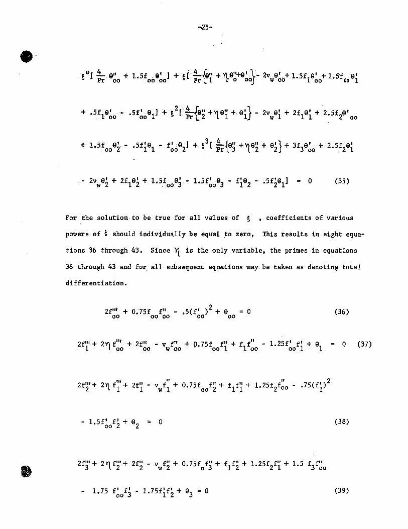
For the solution to be true for a11 values of S ,. coefficients of various
powers of S shou1d individua11y be equal ~o zero~ This resu1ts in eight equa-
tions 36 through 43. Since Yt. is the on1y variable, the primes in equations
36 through 43 and for a11 subsequent equations may be taken as denoting total
differentiation.
2f'" + O.75f f" - .5(f' )2 + e = 0 00 00 00 00 00
(36)
,,," "2 2fll/+ 2Y1 f + 2f" - f + O.75f fil + f f" + 1 25f f .75(f
1') 2 . l 1 1 v w 1 00 2 1 1 .• 2 00 -
(38)
(39)

-26-
(40)
4(911 +V\ 9" +.·9' ) + Pr[- 2v,9' + 1.5f19 1 + 1.5f 9
1' + .5f
19' 1 "L 0000 . W 00 00 00 00
- .5f' 911 = 0 (41) 00
It is obvious that first eqp.1ations 36 and 40 must be solved simul-
taneous1y, after which equations 37,41; 38,42; and 39,43 may be solved succes-
sive1y .. in pairs.
Equations 36 and 40 are non-linear simultaneous ordinary differential
equations wl th tw6 point boundary conditions. They r·èpresent the solution for
heat transfer for a fIat plate without transverse mass flux. Equations 37,38,
39,41,42,43 are inhomogenousordinary differentia1 equat:ions. For example,
equation 37 i8 a third order equation in fI. Since the inhomogeneous terms
(not containiqg fI or ( 1) fo and its derivatives are now known functions of ~ ,

-27-
their values· aTesubstituted from ·the solution of equations 36 and 40. l t
can be easi1y shown from the properties of inhomogeneous equations thatif fIl
18 a solution of. a part of equation ,37 ( aU terms except v fil) when . . w 00
equated to zero i.e. equation ;44
2f"'+ 2Y\ftll +. 2f" + 0.75f f"+'i f" - 1.25fl fI + Q = 0 (44) 1 Loo 00 00 1 1 00 00 1 1
andthat ,if vwf12 is a solution of another part of equation 37 (the homogenous
part and the term vwf~) whenthat part is equated to zero, i.e. equation 45
2f"l + 0.75 f frl + f fil - L 25 f' fI + Q . - v f" = 0 ( 45 ) 1 00 1 1 00 00 1 1 w 00
then fU + Vw
f 12 is the solution of equation 37, Le. f l = fU + Vw f 12 (46)
Using this approach one may obtain for equations 38, 39, 41,42 and 43, the
(47)
(48)
(49)
(50)

-28-
... (51)
where
Substitution'of equations 46 through 51 in equations 32 and 33
resu1ts in
(53)
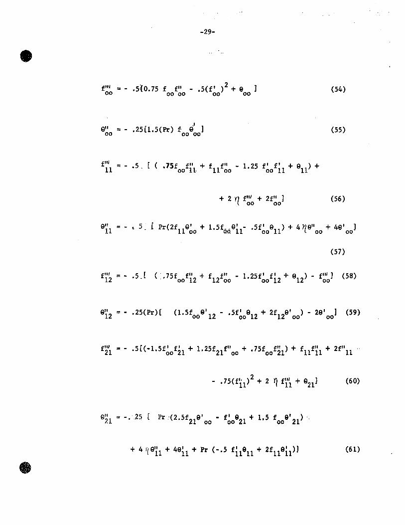
The substitution of equations 46 through 51 in equations 36 through 45,
combined with the requirement that, for the solution to be true for a11 values
of v, the coefficients of al1 powers of v shou1d individual1y be equa1 w w
to zero,results in a set of twenty ordinary differentia1 equations, (54)
through (73).
f lf, =-00
91f =-00
-29-
.5{O.75 f f lf - .5(f' )2 + 9 ]
00 00 00 00
l' .25[1.5(Pr) f 9 ] 00 00
+ 2 Y1 f lf' + 2 f lf
] 00 00
(54)
(55)
(56)
e" = - ,5 l P (2f e' + 1 5f e' .5f' e ) + 4 'l9" + 4e' ) 11 r 11 00 • 6.6. 11- 00 11 00 00
e" = - • 25 (Pr )[ 12
e" /.1
(57)
(1.5f .. e'12 - .5f' 912 + 2f129' ) - 29' ] (59) 00 00 00 00
(61)

fit' = -22
+ f fil - fil ] 12 12 12
(63)
(64)
(65)
(66)
(67)

":31-
(68)
(69)
f3~ = -.5 (. 75foof"33-1. 75f~of33+1.5f~of33+933) + 2 Y/.f23+2f23-f22
(71)
(72)

-32-
(73)
The boundary conditions associated with these equations are:
At 'r( = 0:
r = l, u = 0 T == T , w
f'(O) = f(O) = 0 9(0) == 1
(74)
f(O) = foo(O) = fll(O) = f12
(0) =f21
(0) •••• = f33
(O) = f34
(0) = 0
(75)
900
(0) =1, ~\l(O) =912(0) ••• =93/0) =9
34(0) =0 (76)
At ~ = co:
u = O·, T = Tco

-:33-
Numerical .Solution
Equations 54 through 73 are ordinary differential equations representing
the fundamental momentum and energy transport in the axi-symmetric free con-
vection boundary layer around a vertical cylinder with uniform transverse mass
flow. These equations, being coupled, are solved in pairs at Pr = 0.7.
Equations 54 and 55, which constitute the first pair, are non-linear equations,
while the remainder are a11 inhomogeneous. The first group of terms on right .
hand side of equations 56 through 73: is the homogeneous part, the remainder
being the inhomogeneous part. Solution of any pair of equations requires the
values of the inhomogeneous terms from some or all of the previous pairs.
The solution of equations·54 through 73 has been carried out by numerical
integl'ation using the Kutta-Simpson method. The equatioŒl in each pair are res-
pectively third and second order simultaneous differential equations. For
numerical integration they are reduced to a set of five differential equations,
each of first order. Five boundâry cOnditions, 74 through 78, are available
for the solution. However, the Kutta~Simpson method is applicable only ta initial
v~lue problems. This forced us to choose two more initial conditions (i.e.
fil (0) and e' (0» arbitrarily. Withthese arbitrarily chosen values of 00 00
fil (0) and Q' (0), equations 54 and 55 are solved. This is repeated for 00 00
different combinations of fil (0) and Q' (0) until the conditions at infinity 00 00
are matched. The numerical computation was do ne on an IBM 7044 computer.
For computation, some numerical value,~~,of the independent variable, yt ,

-34-
is chosen to represent infinity. The implication of f' (~) = 0 is that the 00
value of f' 00
at ~ ~ is zero and remains zero no matter how far beyond Y1. ~
we may go. This required that at and beyond yt~, fil' fil must al so be 00' OP
zero. Similarly e" e' 00' 00
along wi th e 00 must also be zero at and beyond ~~.
Numerical integration.with. correctly chosen values of fil ( 0) and 9 ' ( 0 ) 00 00
. f f 1 fil fil' and g1ves 00' 00' . 00' 00 e ,e' ,.9" 00 00 00
as functions of l1 values are used in the solution of the succeeding pairs of equations.
These
Solution of each pair of the inhomogeneous equations 56 through 73 1s ob-
taine~ by a linear combination of the solutions of the homogeneous part
equated to zero and the full equations. A set of values of f~b(O) and e~b(O)
(a = 1,2,3; b = 1,2,3,4) is chosen to satisfy one of the two conditions at
infinity i. e. A Hnear combination of values of fil (0) ab and.
9~b(O), obtained for thehomogeneous part and the equations containing aIl the
terms, is made to satisfy f' (~) = O. ab
The interested reader is referred to
the details of the methods of solving of non-linear and inhomogeneous equatigns
given in Appendix '. Results'have been calculated to eight significant figures
after the decimal. The worst matching of the boundary conditions· at infinity
is four places after the decimal. This result is qui te good, taking into con-
sideration that the error gets accumulated as results from one set of equations
are fed to succeeding sets.
The values of f~b(O) and 9~b(O) (where a = 0,1,2,3 9 b = 0,1,2,3,4)"
which match the solution of equations 54 through 73 at "'l~ and beyond that, are
given in Table 1.

-35-
TABLE 1
fil (0) = 0.6789105 00
Q' (0) = -.2497558 00
" fil (0) = 0.11118057 Qi.1(0) = -.22487495
11
fil (0) = -.08811011 Qi.2(0) = 0.17144587 12
fil (0) = -.01239087 Q21(O) = 0.05675445 21
fil (0) = -.02569557 Q22 (0) = 0.00243219 22
fil (0) = -.0369464 Q'I tO) = -.03582649 23 23,
fil (0) = 0.01741969 931
(0) = -,.02799335 31
fil (0) = 0.0482692 932
(0) = -.00630005 32
fil (0) = 0.05879534 933
( 0) = 0.02501713 33
fil (0) = 0.01013797 934
(0) = 0.00039481 34

-36-
Local Heat Transfer Results
Heat transfer results are presented in terms of the Nusselt ·number
Nu = i/(k/h), the ratio of a length dimension to the fluid film thickness
if the whole of the heattransfer were by, conduction.
hi Nu ='k" 1
(T - T ) co w
( k o~1 ) 25 ai_ k r=a '
Nu = x ( _ ~ (Tco - Tw) ~:I ) k(T -T ) r=l
co w
X d9 oYl Nu = - - (-) (-) = -a o~~=o orr=l
2G x3/4 e' (0)
= (NU)(Gr)-1/4 = _ 29'(0) 4
Substituting equation 53 in equation 80
= -
(79)
(80)
(81)
The product of S and v is F w w It is proportional to the
ratio of transverse flow Reynoldsnumber, v x _w_ to the Grashof number.
v

" .,.:J 7-
Therefore equation 81 can be rewritten as
= -
(82)
The first term on the right hand"side of equation 82 represents the
surface temperature gradient along a flat plate for pure heat transfer. The
second and third grou~of terms represent respectively, the third order correction
for the effect of curvature, and the correction for the transverse flow. The
fourth group of terms gives the correction for the interaction between curvature
and transverse flow effects.
For the case of pure heat transfer on a flat plate,
and thereforel
(Nu)F =0 w
;=0
= -
or (Nu) = 0.5 (4Gr )1/4 F =0 w
e=O
2(9' (0)) = 0.4995'= 0.5 00
For pure heat transfer on a circular cylinder, F = 0 w
; = 0,
(83)

-38-
Therefore the fract10na1 1ncrease 1nheat transfer due to the curvature 1s
g1ven by the second group of terms 1nthe r1ght hand s1de of equat10n (85)
(Nu)S =0
F =0 w
= 1 + [s 8il (0) + ~ 2 9' 21 (0) + s3 931(0) J 9' (0) 9' (0) 9' (0) 00 00 00·
(85)
The change 1n the rate of heat transfer due to transverse mass f10w for a
fIat plate 1s g1ven by equat10n 86
(Nu)! =0
(NU)s"O
F =0 w
~ 91' 2(0) 2 92'3(0) + F3 93'4(0) ] .. 1 + [F + F
w 9' (0) w 9' (0) w 9' (0) 00 00 00
(86)
S1m11arly, for a c1rcular cy11nder, the relatlonshlp ls:
(Nu)
(Nu)F -0 w
- 1 + [Fw912(0)+F;923(0)+F;934(0)]+ftFw922(0)+ ~2Fw932(0)+~F!933(0)
.9~0(0) +ft9il(0)+~292l(0)+t393l(0) ]
(87)
-39-
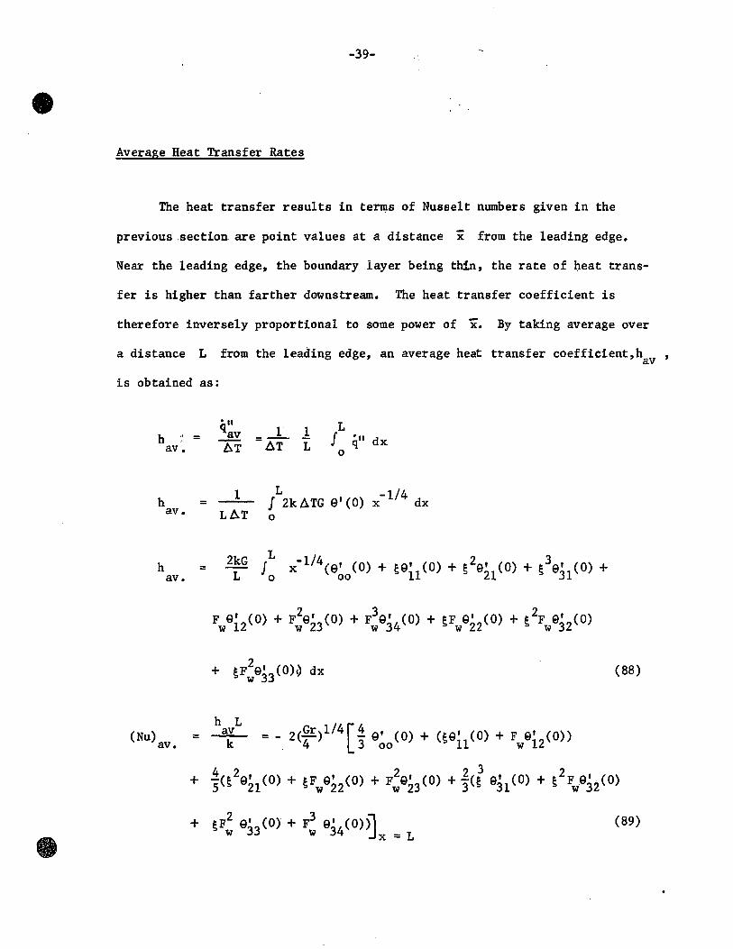
Average Heat Transfer Rates
The heat transfer resu1ts in terms of Nusse1t numbers given in the
previous .section are point values at a distance x from the 1eading edge.
Near the 1eading edge, the boundary layer being thin, the rate of heat trans-
fer is higher than farther downstream. The heat transfer coefficient is
therefore inversely proportiona1 to some power of x. By taking average over
a distance L from the leading edge, an average heat transfer coefficient,h , av
is obtained as:
h av.
h av.
h av.
(Nu) av.
... = qav
ÂT
1 = LAT
2kG = L
h L =~
k
L 1 1 J '11 = AT L q dx 0
L -1/4 J 2k ÂTG e' (0) x dx 0
L x- lI\e' (0) + se' (0) + s2e' (0) + s3e, (0) + Jo 00 11 21 31
= - 2 (Gr) 1/4 [~ e' ( 0) + (s e' ( 0) + F Q' ( 0) ) 4 3 00 11 w 12
+ sF2 e' (0) + F
3 e' (0»)1 w 33 w 34 :.lx = L
(88)
(89)

-40-
Mass Transfer with or without Heat Transfer
From an examination of the equations for heat and for mass transfer,
it is apparant that under certain conditions the mass and energy transport
equations are analogous. In the absence of a chemlcal reaction and thermo-
diffusion and diffusion-thermo effects, the mass transport equation can be
written as
_ Oc + _ Oc u ox v~
D =:
r o (_ Oc ) air~ (90)
where c is the concentration of one of the components, D ls the diffusi-
vit y, and ~ is the Schmidt number, Sc. If a dimensionless concentration
difference is defined as equation 90 can be non-dimen-
sionalized to equation 9.1.
(91)
Equation 91 is similar to equation 7 except that Sc has replaced Pro
For the case of pure mass transfer from a vertical cylinder in a
still atmosphere, the driving force is the concentration difference between
the fluid near the surface and that far from it. This concentration difference
is also responsible for the creation of free convection because of the density
difference. Therefore, in the momentum equation, the body force takes the
form g( P -Poo l'co
). If a Grashof number for mass transfer is defined as
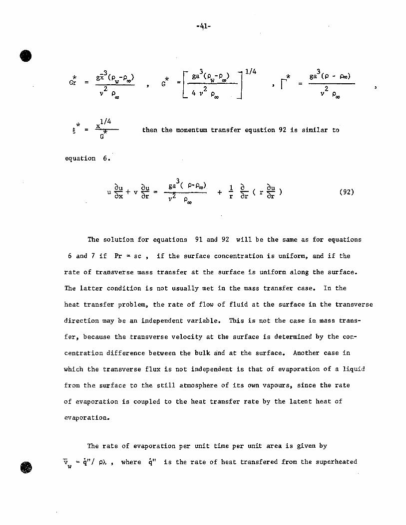
gx3(p -p ) =[ 3 T/4 3
* * ga (p -p ) * ga (p -
Gr = w 00 G w 00 r = 2· 2 2
v Poo 4 V Poo v Poo
* 1/4
x S = * then the momentum transfer equation 92 is simi1ar to
G
equation 6.
Ou + Ou u~ var = 1 0 ( ou)
+ r or r ar
Alo)
(92)
The solution for equations 91 and 92 will be the same as for equations
6 and 7 if Pr = sc, if the surface concentration is uniform, and if the
rate of transverse mass transfer at the surface is uniform a10ng the surface.
The latter condition is not usua11y met in the mass transfer case. In the
heat transfer prob1em, the rate of f10w of f1uid at the surface in the transverse
direction may be an independent variable. This is not the case in mass trans-
fer, because the transverse ve10city at the surface is determined by the co~-
centration difference between the bu1k and at the surface. Another case in
which the transverse flux is not independent is that of evaporation of a liquid
from t.he surface to the still atmosphere of its own vapours, since the rate
of evaporation is coup1ed to the heat transfer rate by the latent heat of
evaporation.
The rate of evaporation per unit time per unit area is given by
v = él" / pl.. , w
where -II q is the rate of heat transfered from the superheated
,
1
-42-
vapours in the suroundings to the surface covered with a layer of 1iquid
at its boi1ing point, ~ is the latent heat of evaporation, and p is the
vapour density at a suitab1e temperature between that of bu1k and at the
surface.
q" = k ~=a =-2GkÂT
a . x- 1/4 e' (0)
v = _ 2(~ ) kAT w ax p~
e' (0) 2 = - sr- v k A.T e' (0)
vp~
v a --!...- = v
v w = - 2 k ) (~) I( c vp ~ e' (0)
p
Vw = - l ( !r> e' (0)
A measure of the driving force for heat transfer is given by the
dimension1ess quantity, B = c ÂT 2 which is the ratio of change ~
(93)
(94)
in
entha1py of the evaporating vapours às they are heated from the saturation
temperature to the bu1k temperature, to the latent heat of evaporation.
The equation, ana1ogous to 94, applicable to the case of mass transfer
where it is the concentration difference , t:. c, which causes free convection
is as follows:
-* B* * v a 2 v = _w_ = - ... ~' (0) (95) w v ~* Sc
* Âc where B = P 'w
-43-
lt has been shown by Sparrow and Cess (24) that the heat transfer
results for a flat plate with constant transverse flow do .not differ very
( 6 ) . - _-1/4 much·from those obtained by Eichhorn. for the case where v œ x • w
This conclusion will also be established by the present study. Sparrow and
Cess termed thus phenomena as,. 'the boundary·layer has poor memory', i. e.
the rate of heat transfer is not affected by the amount of upstream trans-
verse mass flow. lt 18 hoped that. this independenée of heat. t~a:nsfer· of the
transverse .velo.city distribution atthe surfac~ re~ain,s true for.a cylinder also.
In view of these facts, it is proposed that no great error will be intro-
duced if in equation 94,95 , the values of temperature and concentration
gradients, 9'(0) and (11'(0), are subtituted .trom the heat transfer solution
for the case of uniform v w
Therefore equations 94 and 95 can, be expanded
into equations 96 and 97 respectively.
(96)
0' ( ) *2) 3 0' (0' * n' *2 0' *3 " + 23 0 Vw +~ ( 31 0)+ 32(0)vw + 'lJ33(0)vw + 34(0)vw )J (97)
For some particular values of g and B, a value of v can be found w

-44-
which will satisfy equation 96. Thua plots of v , vs. s with B as a w
parameter will give the value of Vw
along the. length of the cyUnder at
. C.,/).T ). different values of B(L e.!:: The sameplot 18 also vaUd for
equation 97 if v , S w and
À.
* * B are replaced by Vw
' S , * B respectively.

DISCUSSION OF RESULTS
Temperature and Velocity Profiles:
Temperature and velocity profiles in a boundary layer flow reveal much
about the mechanisms governing the transport processes. This is especially
helpful in complex transport processes for which it is difficult to visualize
the effect of interaction of the processes occuring simultaneously. Equations
98,99 give the temperature and velocity profiles for heat transfer with trans-
verse mass flux around d. vertical cylinder at P:C' = 0.7.
(98)
(99)
The effect of YI. ' t'.he fllnction of distance in the transverse direction~ on e
and fi, the dimensionless temperat~re and longitud~nal flow parameters respec-
tively~ is given in figures 2 and 3. Four combinations of ~ an.d F , w
the
curvature and the transverse flow parameters respectively, are considered for
illustration.
Since suction causes a flow towards the surface, conditions in the near
vicini ty of the surface are in th:'i.s case more strongly inHuenced by the bulk

e
8
ro lE: 1
curve ~ F.
a 0'2 0'0
0"8 b 0'2 0'5
c 0'2. 0'5 d 0'3 075
'-------- --
0'6
1 Note t he change in scale
0'4
Q.; '< ~
0'2
o·o-l---. '. 0'0 2 4 6 8
'tt FIG.2
10
9 as a Function of yt
15 20
e
25 30

• :g 82 g of
1 • • ." !'I "tif ~ 0 00
f a t
• • .. ~ a .. . .. e u •
s:::--... 0
If) c 0
c:; .. .. u
(ii: §
"" .. Il ... ;..
0 b
;t 0 0 0 g ~ 0 N ...
0 0 0 0
-:..
-r48-
flllid conditions. Withblowing~ on· the other hand, the temperature and
fluid velocity at the surface influence the flow field for a considerably
greatet' distance fromthe surface. Thus the temperature gradient at the
surface is higher in case of suction, and lower.for blowing, as compared to
the gradient without transverse mass flux. Alternately~ the effect of trans-
verse mass flux May be described in,terms of a reductionor an.increase in
the boundary layer thickness caused by suction or blowing.
Corresponding effects of transverse mass flux·for the longitudinal flow
variable, fI, are shown in figure 3. The maximum value of fI and hence the
maximum axial velocity in the boundary layer decreases with suction and in-
crease with blowing. The distrubance ahownin the curve,d of.Jigure 3 becomes
more pronounced at higher values of F as the boundary layer becomes w thicker.
With excessive blowing the transverse flow will dominate the longitudinal flow
caused by the density difference.
Accuracy of the Results.
Fo~ this analysis to be valid, an important requirement is that the
boundary conditions at '1 = 00 be met. For YL ,,30 to be a satisfactory
numerical approximation for Y'\. =.oor the physical conditions require that 9 and
f' be zero and remain so for alljvalues of~ > 30, and that the higher deri
vatives of 9 and f' follow the samerequirement. Figures 4 and 5 illustrate for
the particular value of ~ = 0.3 and F = 0.75, w the way in which the boundary
conditions for Y) = co are met at '1. = 30 or earlier. For aU other values of ~
and f, it is also true that 9 = 9 ' = 9" = 0 = f' = f" = fil' • W

----~----------------------~----~;
~ g • Ct • N .. • .= 00 1
':;'> , p !!!
• ~ 1 1/ ...
0
• 0
12 o·
2 004
" u
! v
= ~C; iD o -il 1&.
i ~
ri e

______ 1 ft
~
1
1 • • .. f 1
G ~E J -~i j s:::'"
~
~ • a 0 ... 60 U a :1 ...
11).
e ci" iL-1W
"'-a " ...
e ..

~
----~--~~----r__,r_--------_T!
• N
ID 0\
\ \ \ \ \ \ \ \ \
1 1 1 "
, 1
1 1 1 0 1 1 1 1 1 1 1 , 1 1 1 1 1 1 1 1 1 " Il
,/1 Il
III /1/ 1 ~ ~
• l
,'''IIU 8N1Gyn :10 % n l'IIIU 113CIItO GIIIH!
• o

-52-
Another factor affectingaccuracyis the repres~ntation.of the functions
f and-ein_series form.in ascending powers of ~. In this expansion it was
assumed that the sum of the.terms containing fourth and higher powers of è was less than the term .. containing the third power of ~. Because it is diffi
cult to prove this point directly, which would require the calculation of a
large number of termsin the series, a limit was set on,the system variables
so that the third order term was small relative to the sum of the leading terms.
The dependence of the third order term, as a percentage of t~e sum of the leading
. terms of the series, .. is plotted in. figure 6 as a function of ~ and F w
Withinthe limits -1 < F < 1 and 0 < ~ < 0.85, it 1s observed that the w
third order term is never more than± 4% of the sum of the leading terms.
Because the results for cylirider have been obtai.ned by a perturbation technique,
the solution is not applicable ta cylinders of bigh curvature, i.e. for
~ > 0:85, for which the neglected terms of the series would become significant. \,. ..
6 . For a Grashof number of 4 x 10 , the limitation of ~ < 0.85 corresponds ta
cylinders of a length ta diameter ratio up· ta 27. With respect ta limit on
transverse flow, it is of interest to note that if the limits for F were extended w
ta -5 < F < 1.5 , the third arder term would become at the worst -10% of the w
sum of the leading terms. The error caused by suction is smaller than that for
the same rate of blowing beeause the boundary layer is thinner and more stable.
Local Heat Transfer Results
The local heat transfer results for blowing and for Buetion, given earlier
as equation 82 are represented graphieally on figures 7 and 8~ The transverse
mass flow parameter F is preferr:ed ta v = (val J) ), when è is used as the w w w

--r -,.....j • ...... ~I.;t '-' ......
::J Z '-'
.., e
rO'I~-----------------------------------------------------------------------------------------------,
0"8
0"6
0"4
0·2
0"0 , 1" O··, 0"2 0"3 0"4 0"5
FIG.7 F
w 0"6
Heat transfer results for blowing
• • •
"PRESENT WORK
CRe'.24:"J CRef. 10 ) att = 0
(Re'. 3 )
( Re'. 6 ) Vw .-114, t.= 0
O·SO
0·40
0·20 0·'0 00"5
~~-----------
07 0"8 0·9

0 •
0 .,
• ! w 1 • . J - _1_ 1_---_ ·r-
0 .... 10 ... ~ • ~ • • ~ - -n
1 1 • • •
~
.~ b 1
~~~~~--~--~--~~o' ~ 0 S '0
a 0 ... ... U :1 • t ... •
CD~ .C!i~ "_II &&ok
11 ... • q 11 ... .. Il =

Ct
n~i~-------------------------------------------------------------------'
?,n .P.!)
11-'-' ~ ''Ç' ",Iv -.J ........ .:J ::2 ....."
L-..I ----.. :;tr-. I~
~It '-' ........ .:J ;z -./
/-.J
r
I"2-CL_---~ "aO·'O
.·0 1 -0". -a. -(M -02.... 0·0 0·2 0"4 O·. O·.
FIG. 9 Comparison of local heat transfer results for a cylinder vith fIat plate heat transfer re.u1ta
e

o .. .r
r"' 1 ..... ~,. -..... ~ z ~ ~r-' ~ 1 .....
~I" .... .... ~ . ....::::...,.,
et
2'0
ra
,'6
,'4
"2
rO
"8
0'6
0·4
0'2
0"0 0'0
--------
01 0'3 0:4 0'5
t. FIG.IO
·tt
ro
• (Re' 21 h F.·O
------_--------r . 0'8
. Fw =-0'8· . .
-0'5
-0'3
-01
-01
0'3 0'5
0'8
0'6 0'7 0'8
ro" n
0'6 • la.
~ ï_ c';j.t ~
0'4 -; ~
~
0'2
0'0 0'85
Compairson of local heat transfer results for a cylinder with and without transverse mass flux.

-57-
second parameter, because the radius appears both in ~w and ~. but not in
The flow variable F = (v x/V)(Gr/4)-1/4 represents the ratio of the w w
F • w
transverse flow Rey~olds number to a functionof Grashof number. The choice
of F. and ~ thus facilitates determination. of the effect. of curvature. Howw ç
ever, it should be noted that ~, also represents the effect of distance from
·the leading.edge as in' figure 12·whet.e x does not appear in the ordinate.
The rate of heat transfer may ~e seen to increase for suction and decrease
for blowing. A flow of fluid outward fromthe s~rface and originating at the
surface temperature, acts .to reduce the temperature gradient at the surface, and
~hus~r.educing.the heat transfer rates. A flow of fluid towards the surface has,
naturally,the opposite effect.
The curve for ~ = 0 . in figures 7 and .8, which ·represents the heat trans-
fer rate to a flat plate, differs at .higher rates of blowing and suction from
the rates givenby Sparrow and Cess (24). Since Sparrow and Cess considered
only a first order:correction for the transverse flow, their results are lower
than those obtained in the present work, for which a third order correction
has been applied. The results obtained for a fIat plate by Mabuchi (10) and
by Brdlik. and Mochalov (3) are in good a~eement with tbe present work for
blowing.For suction, however,our results are between tbose given by Sparrow
(24) and tboœ of Mabucbi (10), Brdlik and Mocbalov (3). Mabucbis and Brdl1k and
Mocbalov assumed 'similar profiles' for velocity and temperature in the boundary
layer, and. for the transverse distance variable in both profiles,used a fourth
order polynomial in terms of the ratio of transverse distance to boundary layer

-58-
thickness. Since velocity .and temperature profiles are in fact nbt'similat'
in the boundary layer, the perturbation technique was used by Sparrow and Cess
(24) and this study. It is believed that the result:~ of the present analysis
is more accurate than those of the earlier studies.
When the fIat plate results of the present study are compared with
the exact solution given by Eichhorn (6) for the case of a transverse flux
which is inversely proportional to the on~fourth power of. the distance from
the leading edge, good agreement is found for moderate rates of blowing and
suction~ . Deviations are higher for suction than for blowing. However, the ,
important conclusion is that the local heat transfer rate is influenced very
little by the upstream transverse velocity distribution. This fact was first
noticed by Sparrow and Cess (24)
~ 1 - -1/4 The effect of curvature is indicated by the parameter, ~= (-) x(Gr/4) , . a
the ratio of boundary layer thickness to the radius of the cylinder. It may be
seen from figures 7 and 8 that for any value of F , the rate of h~at transfer incrE w
ses as the cUlVFlture variable increases, the mimimum value being for a flat plate.
A physical picture of the effect of curvature onheat transfer may be given by
considering the value of heat flux for a flat plate at ... particular surface and
environment temperatures T and Too. As the surface acquires curvature in w
becoming a cylinder,whilè the same T w
and Too are maintained, the point
values of heat flux at aIl points in the boundary layer wou1d be decreased if
the heat transfer at the wall were to remain constaQt. This reduction wou1d
resu1t from the fact that for a cylinder the area for transverse flow of heat
1
.. 59-
or mass in the boundary layer increases in proportionto the Tadial distance.
If the heat flux at aIl points in the boundary layer were to decrease, the
temperature difference (Toa - T ) . would al80 decrease. w Thus for the tempera-
tures Tao and T w
to be maintained as curvature increases, it necessarily
follaws that the heat flux at the wall must increase. The magnitude of the
increase is given on figures. 7 add 8.
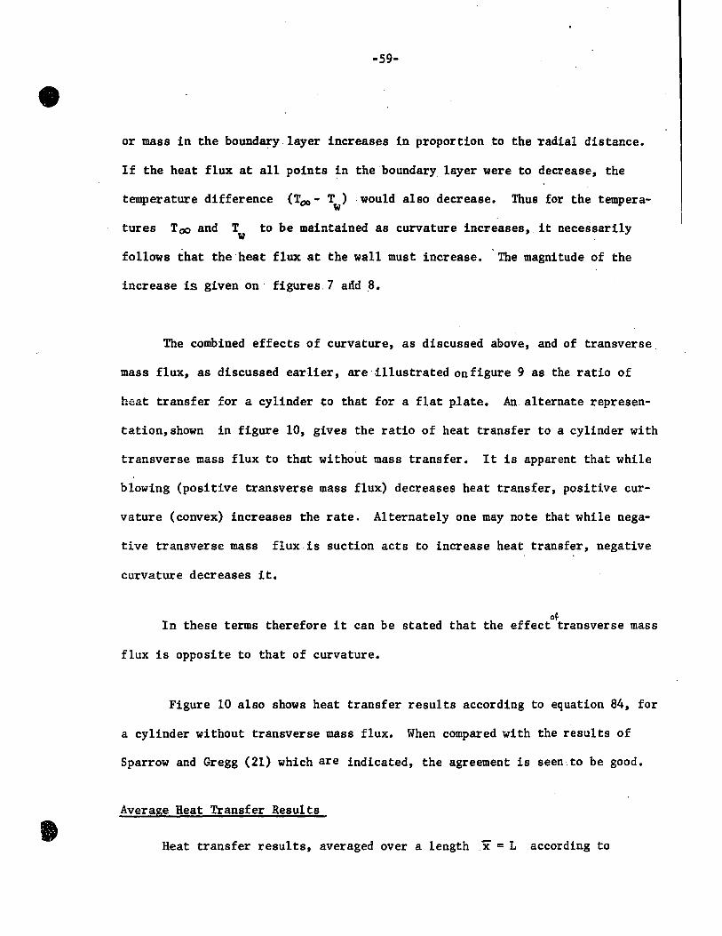
The combined effects of curvature, as discussed above, and of transverse.
mass flux, as discussed earlier, are Ulustrated on figure 9 as the ratio of
heat transfer for a cylinder to that for a fiat plate. An alternate represen-
tation,shown in figure 10, gives the ratio of heat transfer to a cylinder with
transverse mass flux to that without mass transfer. It is apparent that while
blowing (positive transverse mass flux) decreases heat transfer, positive cur-
vature (convex) increases the rate. Alternately one may note that while nega-
tive transverse mass flux is suction acts to increase heat transfer, negative
curvature decreases it.
Ot In these terms therefore it can be stated that the effect transverse mass
flux is opposite to that of curvature.
Figure 10 also shows heat transfer results according to equation 84, for
a cylinder without transverse mass flux. When compared with the results of
Sparrow and Gregg (21) which are indicated, the agreement is seen. to be good.
Average Heat Transfer Results
Heat transfer results, averaged over a length x = L .according to

~ ________________ ~p-~~~ __ ---------r~

-61-
equation 89,' are given in figure 11. The average value of heat tra~sfer co-
efficient is higher than the local value at x = L, beca~se of the decrease of
the local heat transfer coefficient with distance from the leading edge as the
boundary· layer thickness increases. However, the effects of ~ and F on the w
average Nusselt number are similar to tl)at for the point values given on
Figures 7 and 8.
Mass Transfer with or without.Heat Transfer.
In the analysis presented to this point, a degree of freedom·has existed
between the variables, transversevelocity, and the heat transfer driving
force, AT. HOlrever, if the source or the sink of transverse mass flow at the
solid surface occurs by means of a phase change, then the transverse velocity
and driving force become linked. In the case of coupled heat and mass transver,
the mass flux will usually not be constant over the surface. However, it has
been pointed out earlièr that the boundary layer has 'POOl' memory' i.e. the
rate of heat transfer is not much.affected by the transverse mass flux distribution
at the surface. Thus it is proposed that where transverse mass flux distribu-
tion depends on the local rate of heat transfer, the solution for the uniform
transverse mass flux distribution can he applied without large error.
Figure 12 gives the rate of transversemass flux v as a function of ç w
* ~* * and B for heat and mass transfer and v as a function of ç and B for pure w
mass transfer. Since~, with ordinate v =(v a/V),represents longitudinal C;: w w
distance from the leading edge, figure 12 gives the rate of transverse mass flux
as a function of length of the cylinder. In.this analysis, the theoretical trans
verse mass flux increases without limit as the leading edge i.e. ~ = 0 is
approached, since the boundary layer thickness is taken as zero at this point.

• b
• 0
G
• 0
!fi 0
~------~------~------~------r-------r------+g g
... • ."
b ....
1 ., j ~ .8 ., ... :a
N1 "":'fI se ... ... :a
• li • .. ~ a li • i Il •
1

-63-
Downstream fromthe leading edge theboundary layer thickness increases in
proportion.to the one-fourth power of the distance from the leading edge. At
higher values of ~ , the mass flux may be seen from figure 12 to approach an
asymptotic value.
Li (9) has measured the rates of evaporation of water on flat plates
in natural convection at hightemperatures. For the evaporation rate he obtained
o with a 2 inch long plate in an environment at 374 C, which gives a Grashof
5 number of 3.24 x 10 , the value of the flow variable F = 0.47 may be calculated.
w
This experimental value of F is well within the range of validity.of our w
theoretical results.
For the case when the heat transfer by radiation 18 significant, the rate
of evaporation by radiation may be added to the right hand side of equation 96,
and the value of v may be found to satisfy this equation. w

.. CONCLUSIONS
For heat transfer, by laminar natural convection with uniform trans
verse massflux; for a vertical cylinder, a numerica1 solution has been
obtained, which depicts the effect of curvature and transverse mass flux.
Qwing to the application of perturbation technique this solution is not
valid for very long and thin cylinders.
It has beenobserved, that
(i) For aIl values of transverse mass flux, the effect of curvature,
convex to the surroundings, is to increase the rate of heat transfer,
Conversely, the rate of heat transfer is decreased if the curvature to
the environment becomes concave.
(ii) For aIl values of curvature, from'a fIat plate to the highest value
for which the solution obtained remains val id, the heat transfer rate
is decreased by blowing (positive mass flux) and increased by suction
(negative massflux).
(iii) The effect of transverse mass flux is opposite to that of curvature.
(iv) The phenomena of 'poor memory' of the boundary layer has been confirmed
for a flat plate and it i.s hoped to be true for a cylinder a1so. This
provides a method for the estimation of transverse mass flow rates for
a coupled heat and mass transfer process e.g. evaporation of a liquide
Evaporation by radiation can be taken into account as long as the mass
transfer rate conforms to the limits imposed.

BIBLIOGRAPHY
1. Bourne, D.E.,. and Ward1e, S., J. Aero, Science, 29; pp 460-67, (1962).
2. Bourne, D.E., and Davis,D.R., Quart. J. Mechanics and Applied Mathematics,
11; pp 52-66, (1958).
3. Br~k, P.M., and Mocha1ov,. V.A., Int. Chem. Engg. 5; 4, pp 603-7, (1965).
4. Brindley, J., Int. H. Heat Mass Transfer, 6; pp 1035-48, (1963).
5. Cess, R.D., Advances in Heat Transfer, vol. 1, Academie Press, New York, 1964).
6. Eichhorn, R., J. Heat Transfer, C82;3, pp 260-63, (1960).
7. Kelly, H.R., J. Aero, Science, 21; (1954).
8. Kemp·',N.H., A.I.A.A., 2; (196t..).
9. Li, F.S., 'Natural convective Heat and Mass Transfer from vertical plates in
High temperature surroundings' Ph.D. Thesis (McGi11 University, 1965).
10. Mabuchi, Ikuo, Bulletin of Japan So.c. Mech. Engrs., 6; 22, pp 223-30, (1963).
Il. Mathers, W.G., Madden, A.J., Piret, E.L., Ind. Eng. Chem., 49; pp 961-68,(1957).
12. Millsaps, K., and Poh1hausen, K., J. Aero, Science, 25; pp 357-60, (1958) •
13. Nakamura, H. , Bulletin of Japan Soc. Mech. Engr.8., 5; 18, pp 311-14, (1962) •
14. Oliver, C.C., and McFadden, P.W. , J. Heat Transfer, C 88, 2, (1966).
15. Ostrach, S. , N.A.C.A., T.N. 2635, (1952).
16. Ostrach, S. , N.A.C.A. , T.R. 1111, (1953) •
17. Schuh, H., Reports and Trans. 1007, AVA Monograph, BritishM.A.P. (A~ri1 1948).
18. Somers, E.V., J. of Applied Mechnics, 23; 2, pp 295-301, (1956).
19. Seban, R.A., and Bond, R., 18; pp 671-75, (1951).
20. Sparrow, E.M., and Gregg, J.L., Trans. Am. Soc. Mech. Engrs., 78; pp435-40
(1956).

-66-
21. Ibid., 78; :pp 1823-29, (1956).
22. Ibid., 80; pp 3.79-86, (1958).
23. Ibid., 80; pp 879-86, (1958).
24. Sparrow, E.M., and Cess, R.D., J. Heat Transfer, C 83; 3, pp 387-89,
(1961) •
25. Sparrow, E.M., Minkowycs, W.J., Eckert, E.R.G., J. Heat Transfer,
C 86; 4, (1964).
26. Sparrow, E.M., Scott, C.V. Forstrom, R.J., Ebert, W.A., J. Heat Transfer, C·87; 3, (1965).
27. Sparrow and Lin, Int. J. Heat Mass Transfer, 8; pp 437 (1965).
28. Sparrow, E.M., Yang, J.W., Scott, C.J., Int. J. Heat Mass Transfer, 9; pp 53-61 (1966).
29. Sparrow, E.M., Minkowycz, W.J., Eckert, E.R.G. J. Heat Transfer,
C 88; 3, (1966).
30. Sparrow, E.M., Starr, J.B., Int.J. Heat Mass Transfer, 9; 5,
pp 508-10, (1966).
31. Tewfik, O.E., Yang, J.W., Int. J. Heat Mass Transfer, 6; pp 915-23 1
(1963).
32. Wanous, D.J., Sparrow, E.M., J. Heat Transfer, C 87; 2, pp 317-19,
(1965).
33. Wi1cox, W.R., Chem, Engg. Science, 13; pp 113-19, (1961).
34. Yang, K.T., J. App1ied Mechanics, 27; 2, pp 230-36, (1960).
35. Zeh, D.W., Gill, W.N., Chem. Engg. Progress, Symposium Series, 61;
pp 19-35, (1965).

NOMENCLATURE
Roman Symbo1s
a radius of the cy1inder, feet
B
* B
C !:::.T P
Ac
lw
., dimension1ess
dimension1ess
C ifi h BTU/1b oF p spec c eat at constant pressure,
c
Ac
concentration of one of the components Ib/ft3
c - c , 00 w Ib/ft3
D diffusion coefficient ft2/hr
F w
b (v- -xl)) ).(Gr)1/4 <:l l' lowing parameter w 4 ' dimension ess
f dimension1ess dependent variable, defined in equation 32
f ,f b a a
G
* G
Gr
Gr*
dimension1ess dependent variables, defined in equation 32,47,48.
[
gj3{T. - Tw
)a3]1/4
dimensionless constant, 4 ))2
g a3
( lw- L) dimension1ess constant -~J)2 1'0..
gj3(T. - T )x3
Grashof number, w, dimension1ess V2
(
_3{ D p') Grashof numberfor mass transfer gx J w -.;lQ)
J),,2 '
1/4
) 2 g acceleration of gravit y ft/hr •

-68-
h heat trapsfer coefficient, Bru/hr ft2 oF
k thermal conductivity, BTU/hr ft oF
L length of the cylinder
Nu Nusselt number, hx/k, dimensionless
Pr Prandtl number, C plk, dimensionless p
q" heat transfer rate, BTU/hr ft2
r distance inradia1 direction, ft
r r dimensionless distance in radial direction, a
Sc Schmidt number, ~ , dimensionless D
T temperature, oF
AT Toc - T, oF w
u velocity in x direction, ft/hr
u dimensionless velocityin x direction, üa/v
v velocity in r direction, ft/hr
v dimensionless velocity in r direction va/v
x distance in longitudinal direction, ft
x dimensionless distance in longitudinal direction
Greek Symbols
0( thermal diffusivity, J~ ,ft2/hr p
r
coefficient of thermal expansion,
3 gt3(Too - T )a
.JI 2 , dimensionless
0-1 F
-69-
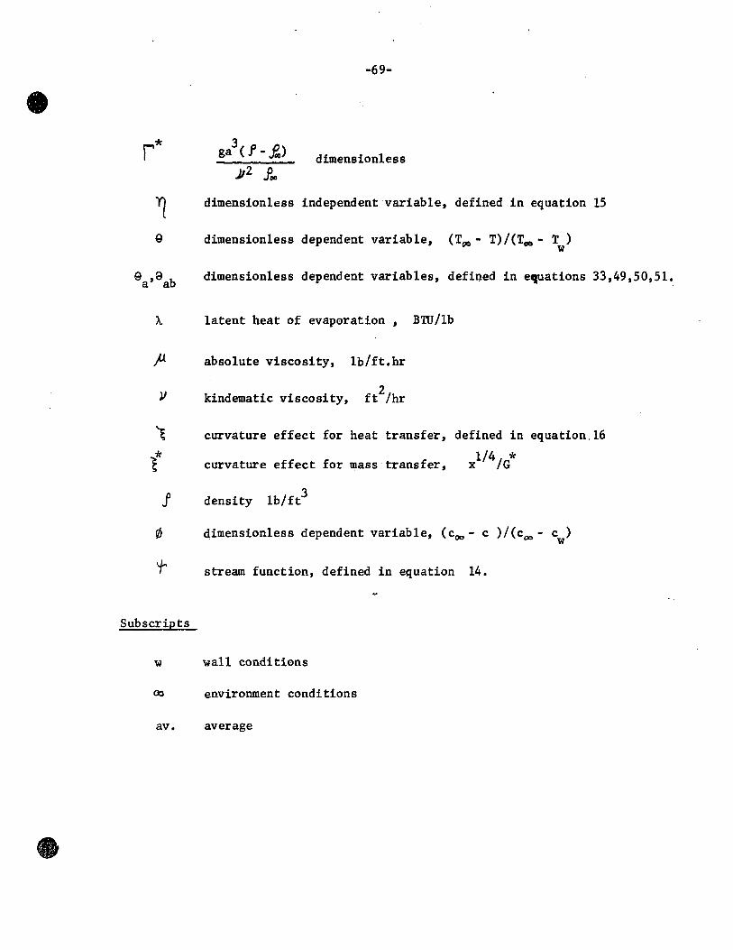
r* dimension1ess
~ dimension1ess independentvariab1e, defined in equation. 15
9 dimension1ess dependent variable, (T~ - T)/(Tf/O - T ) w
9 ,9 b dimension1ess dependent variables, defined in equations 33,49,50,51. a a
latent heat of evaporation, BTU/1b
)J. absolute viscosity, 1b/ft.hr
V kindematic viscosity, ft2/hr
~ curvature effect for heat transfer, defined in equation16
curvature effect for mass transfer,
J density 1b/ft3
dimensionless dependent variable, (coo - c )/(cao - c ) w
~ stream function, defined in equation 14.
Subscripts
w wall conditions
~ environment conditions
av. average

APPENDIX
Simultaneous differential equations of arder higher than one, with j
two point boundary conditions, may be solved by numerical integration on digital
computers. The mass, momentum, and energy transport equations of this study .
were converted to a set of first order equations by defining the dependent varia-
b1e and its derivatives (except the highest one) by new functions. Since initial
values of the functions are required for a numerical integration method, some
arbitrary but reasonab1e guess of the initial values of the functions is made,
and the integration is carried out. The process is repeated with different
initial conditions unti1 the final conditions are satisfied. In the present case
three step sizes, 0.05, 0.10 and 0.20,were used in the independent variable, Yl '
in the regions 0:S ~ < 10; 10:S "rl < 20; 20 < ~ < 30 respectively, because
at higher values: of ~ , the dependent variables ~each asymptotic values.
Since equations 74 through 78 give three initial conditions and two final
conditions, two more initial conditions, f"(O) and 9 ' (0), have to be assumf?d such
that the given final conditions, f"(ao) and 9(oa) are satisfied. Method of
steepest descent was used to minimize the difference between final values f~
and 9~ , obtained by solving equations with assumed initial conditions, and the
desired final conditions, f'(~) and ·9(~). Owing to the presence of local minima
in the case of non-linear equations, the abso1ute minima was found by locating
minima on the locus of (f~- f' (ex») 2 , such that the final condition, (9jfO- 9(00»2
is always minimum.
-71-
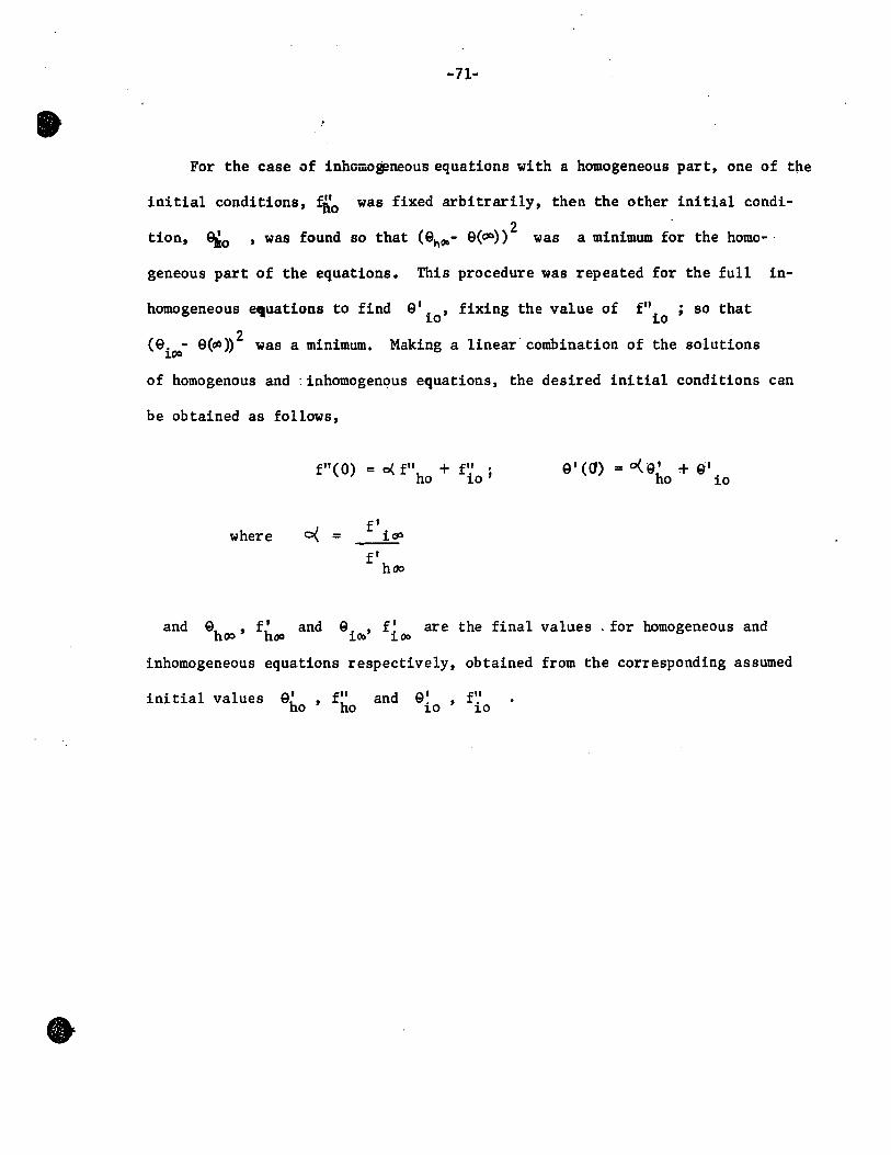
For the case of inhûiiio~neous equations with a homogeneous part, one of the
initial conditions, fao was fixed arbitrarily, then the other initial condi-
tion, 9ko 2 , was found so that (en~- e(~» was a minimum for the homo- .
geneous part of the equations. This procedure was repeated for the full in-
homogeneous e,uations to find el
iO ' fixing the value of fil ; so that 10
2 (e. - e(oO» was a minimum. Making a linear combination of the solutions 100
of homogenous and :inhomogenous equations, the desired initial conditions can
be obtained as follows,
f"(O) = 0{ fil + fil • ho io'
where fI
0< = ~ fI
hl»
el (a) = 0(9 1 + 9'1 ho io
and ehoo ' f hoo and eiOo, f~OCI are the final values. for homogeneous and
inhomogeneous equations respectively, obtained from the corresponding assumed
ini tial values el fil ho' ho and el fil
io' io