naval communications nvk - cdvandt.org · 4 communication and direction finders the aim of this...
TRANSCRIPT
1 Synopsis
Aspects of the German Naval Communications Research Establishment
In reviewing the course of the history of naval communications in the western hemisphere during the last World War, we inevitably have to deal with Germany’s contribution in the fields of wire-less communications and electronic warfare. As in many other countries, there existed a tough rivalry between the Air Force, the Navy and the Army. The first one mentioned, doubtless, car-ried the most young spirit and became the best equipped military service owing perhaps to their principal commander, who was at the same time also the minister of aviation. He had very great influence in the economical and industrial arenas and, most important, played a key-role in their political infrastructure. The Navy was, due to its very conservative nature, responding quite re-luctantly to most new electronic developments. Nonetheless, they were the first to adopt, about 1934-1935, a technology which became later well known as radar. However, system reliability was their main concern and they consequently were maintaining communication-systems whose designs were often dating back to the first half of the 1930s. The Air Force and Army communi-cations will not be discussed in this paper as these, with a few exceptions, had no direct connec-tions with the technology of naval communications. The objective of this paper is to explain some aspects of the work of the German naval research establishment NVK, in respect to naval communications and related technologies. This was the institution in which most of the new electronic related projects were being engendered and, to some extent, were also brought to maturity. © Arthur O. Bauer Diemen, 27 December 2004 The Netherlands stgcdv&[email protected] Introduction We generally may consider that science related to “electronics” was brought to maturity during the 1920s although, the understanding of what became known as the basic theories of wireless were dated back to the novel contributions of Maxwell and Hertz, in the second half of the 1800s. We should wonder that so many new communication technologies were brought on to the market during the first two decades of the past century, albeit that most of the theoretical phe-nomena were not fully scientifically understood. In this respect is it very interesting to study the patent applications of those days, in which we will rarely find a relevant scientific explanation concerning claimed inventions. Starting this historical survey we must go back to about 1919/1920. It became clear that the rapidly improving communication technologies in future warfare de-manded a new approach by German naval institutions. They established in Kiel, which was their major naval port, the “Nachrichtenmitelversuchsanstalt” which generally was abbreviated to NVA (and we will further use abbreviations where appropriate). Soon most divisions of this es-tablishment moved to a site called Pelzerhaken (the British wrote it Pelzerhagen) which is about 70 km from Kiel. This location became their main domicile, although their headquarters still remained in Kiel. We may presume that they chose this site because it was quiet and was sur-rounded by grassland so that future expansion would not be a problem. And, presumably, it ac-
2 commodated a navigational beacon which was used by the German Imperial Navy during the first World War. It allowed all sorts of antenna experiments in a low-noise environment and it was also favoured by those who worked on the fields of sonic (sonar) research. (1)(2) After the NVA had been established they set up their organisation structure in the following divi-sions (mentioning here the most relevant):- C = Dezimeter and Zentimeter (Decimetre and centimetre, section) F = Funkwesen (Communication, section) P = Peilwesen (Direction Finding, section) U = Unterwasserschall (Sonic = Sonar, section) Following the course of the history (and ignoring the alphabetic order), we see that the section ‘U’ was responsible for sonic research, which was translated in German language “Unterwasser-schall”, nowadays better known as “sonar”. This latter division was doing rather advanced work and was headed, since 1928, by Dr. Rudolf Kühnhold, who had just received his PhD at the Uni-versity of Göttingen. He was engaged as a civil servant and started his career in Kiel at the Tor-pedoversuchsanstallt or abbreviated TVA. Before Kühnhold became involved in the (research) fields of radar, he soon came-up with the clever idea of “Sum-Difference” procedure (according to (2) this occurred about 1929) with which technology it became possible to distinguish bearings very accurately on a cathode ray tube (CRT). We notice that such a system needs two separate signal sources to determine (ac-quire) accurate bearings. However, its principles will not be explained on this occasion. He ap-plied for a German, of course, secret patent in 1930. Soon after, this technology became widely adopted in the domains of sonic and related technologies. Furthermore, Kühnhold came-up, relatively soon after his engagement, with another clever idea. He considered that what works in the field of sonar must probably also work with electromag-netic waves too. It should not be overlooked that when we compare the formulae used for com-puting radiation fields of acoustic-waves with those used for electromagnetic-waves, there exists a remarkable similarity. His conclusions proved to be correct! We have seen that Kühnhold’s engagement, as group-leader, started with the work in the field of sonic technologies. Most of us are indeed familiar with the circumstance that organisations are, generally, heavily dependent on their annual budgets. Particularly organisations like military services. It can often take years before a non regular budget receives approval. The German Navy was no exception here. To by-pass long and exhausting discussions with superiors, they (division U) searched for a rather flexible (and small) company who could solve electrical and electronic demands without being bogged down in bureaucracy. They came in contact with two young engineers Paul Erbslöh and Hans-Karl von Willisen, who, since about 1931, had owned the Tonographie company in Berlin and who were successfully involved in the fields of sound and gramophone recording. To continue this retrospection: About 1933 Kühnhold discussed, with the two partners Erbslöh and von Willisen, his failed experiments on 13.5 cm wave-length (0.1 watt radiated power), with which he had tried to detect the bouncing phenomena of high-frequency signals on metal ob-jects. In the meantime, Kühnhold continued his experiments with improved Pintsch apparatus on 13,5 cm which used increased transmission power of 0.3 watt (according to (2) they used Bark-hausen-Kurz valve(s) designed by Hans Hollmann, which are also known as retarding field valves). It is a contradiction that most references mention the use of a magnetron! The antenna dipole was, for this experiment, mounted in a parabola disc. On 12 May 1934 Kühnhold was able
3 to measure the distance of the trial-vessel “Grille” at a distance of 2100 m. It is clear that Erb-slöh and von Willisen knew soon about Kühnhold’s efforts. And it is understandable that there was competition as to who would be come-up with a reliable radar-like installation first! Erblöh’s and Willisen’s own attempts had still failed to measure the distance of metal targets, owing to overloading (blocking) of the radar receiver. However, their trials in cooperation at the NVA testing-site, during 12 October and 2 November 1934, ultimately brought the so desper-ately needed results. They were now able to measure distance of vessels for up to 12 km. The German Navy instantly ordered the continuation of this research project for which they very soon found the necessary funds! For the course of the early radar-history, particularly for British readers, is it interesting to know that their patent application was soon rejected because the clerk of the patent office showed, these somewhat bewildered men, Christian Hülsmeyer’s German patent applications 165546 of 30 April 1904 and 169154 of 11 November 1904. These are similar to Hülsmeyer’s British pat-ents 13170 (1904, application 10 June 1904) and 25608 (1904, application 24 November 1904) thus we ought to be aware that these patent applications could be said to represent the birthday of what became known, decades later, as “RADAR”. However upsetting, Hülsmeyer’s claims were serious and he had demonstrated his apparatus successfully during an international shi-powners conference in June 1904 in the harbour of Rotterdam in the Netherlands! To close this sub-chapter, the NVA (ie, the Navy) together with Erbslöh and von Willisen estab-lished a new corporate enterprise (which was in those days a very unusual practice) and which was named: Gesellschaft für elekroakustische und mechanische Apparate m.b.H abbriviated GEMA. (The present German company Gema has no links, whatsoever, with the previous com-pany, as this is Germany’s copyright organisation!) In contrast to practices maintained in Britain, the German governmental organisations frequently relied quite heavily on the private sectors and thus was no different in the fields of radar related technologies. The pre-war years As time proceeded, Germany regained its military sovereignty around the mid nineteen thirties (with a notable disregard for international agreements). The German military complex was ex-panding rapidly and the Navy Communication Research Establishment (NVA) was, of course, following this trend. The headquarters of the NVA was still based in Kiel and moved about 1938 to a newly built, and huge, compound in Kiel-Dietrichsdorf. The NVA organisation also changed their organisation and command structure and got the new designation “Nachrichtenmittelversuchskommando” or NVK. (communication research command) (3) In the meantime the testing facilities at the Pelzerhaken site expanded vastly and more and more space was being occupied to such an extent that villages bordering the area found themselves inside the security zones. (4,p.133-160)
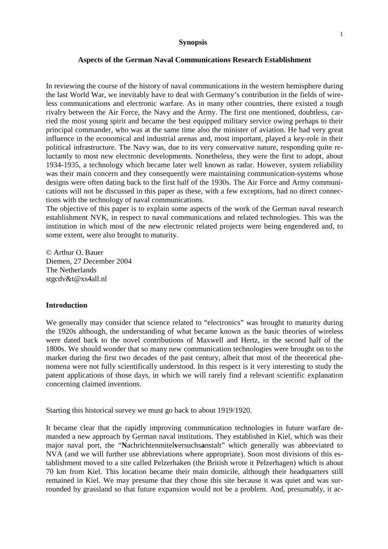
4 Communication and Direction Finders The aim of this symposium is to deal with the subject of naval communications. Such kinds of communications, which may be regarded as most important in military strategies, inevitably have a downside as they may themselves become the subject of interception. The content of messages may, perhaps, be kept a secret but the position of a transmitting source, particularly ships, consti-tutes a major target for military intelligence. Some may have got the impression, that the Allies were, possibly, the only belligerents who were able to intercept the enemies naval communica-tions and that the Germans were not able to compete in this field (owing to most post war litera-ture dealing with Allied naval warfare). To learn if these beliefs had any basis in truth, we have to follow the course of the history and have to go back in time. Watson-Watt’s contribution in the fields of direction-finding The first decade of the past century may be regarded as the period in which nearly all major di-rection finding inventions were born. However, their application was often hampered by the lack of sufficiently adequate valves (amplification). (see also my contributions in the CHiDE pro-ceedings of 1997 and 1998) As we have seen in the previous chapter, the 1920s became the decade in which electronics was gaining maturity. Thus, it is not surprising that direction finding (DF) technologies were also improving and, subsequently, could become a rich source for intelligence agencies world wide. Watson-Watt’s contribution in the fields of DF may be regarded, amongst some others, as a break-through in ‘real time’ direction finding. He and J.F. Herd gave a paper for the Wireless Section of the IEE which was called: AN INSTANTANEOUS DIRECT-READING RA-DIOGONIOMETER, on 3 March 1926. (5, p.611-622) Nowadays we call this a “real-time direction finder system”. Watson-Watt’s paper was widely appreciated and adopted by the scientific communities. Watson-Watt’s paper used for this occasion a basic diagram which, in my opinion, explains the principles of his recently invented DF apparatus very well and which I have never seen repro-duced before.
Figure 1: Watson-Watt’s 1926 receiver concept The left-hand side shows the North-South antenna loop and at the far right-hand we see the East-West antenna loop. The nature of its principle is easy to understand. In the centre of the drawing we recognise the cathode ray tube (CRT). The simplicity of Watson-Watt’s invention is striking.

5 However, the actual realisation of a tuneable multi-band receiver based upon this principle proved to be extremely difficult. The famous British HF/DF receiver FH 4 (which had been in-troduced in 1943) needed, for its full alignment, up to 44 adjustment-settings (which were acces-sible from outside)! However, it may be regarded as a most important and impressive achieve-ment in electronic warfare against the threatening German U-boats. What was the German side doing in the fields of HF/DF? In the 1930s Dr. Maximilian Wächtler became one of the leading personalities of the NVA (and its successor NVK) in the fields of direction finding. In the early 1950s he established the C. Plath GmbH in Hamburg, which latter company would become very famous for their three- channels Watson-Watt direction finder receivers. As the war years proceeded, it became clear to the Germans that they were increasingly falling behind the Allied electronic warfare efforts. It is evident that they were desperately trying to bridge this gap. In late 1942 they established a central directive organisation called: Bevollmächtigte der Hochfrequenzforschung or BHF (Directorate for the High-Frequency Re-search). This institution was given limitless power and could overrule all who were engaged in the field of German electronic warfare. At the same time they also encouraged fundamental re-search. On 23 and 24 March 1944 the BHF held, in cooperation with the NVK, a workshop or so-called “Arbeitstagung”, on “Navigation” at the Ferdinand-Braun-Institute in Landsberg/Lech. (6) Those who attended may be regarded as leaders in their fields. One of the contributors was Maximilian Wächtler whose paper started with a general outline on the advantages and disadvantages of direction-finding. Most DF systems were using the so-called minimum-signal or ‘null’ method in which the antenna was directed as to pick-up the low-est signal level - with or without using a sense antenna. However, the downside of the minimum signal method is, that the bearing minimum tends often to be blurred thus introducing a degree of uncertainty. Wächtler also noted that there exists a DF device which does not suffer from the difficulties en-countered by the regularly used minimum-signal methods and that “erstmalig von Watson-Watt benutzt wurde....” , or which, was first used by Watson-Watt. And he started to explain about their own innovative apparatus “Anlage Lichtbild”, which code-name may be translated as ‘pho-tograph installation’. In an Allied CIOS Report (Combined Intelligence Objectives Sub-Committee) (7, p. 19), they used the description: C.R.D.F. system (cathode ray direction finder). To understand the nature of direction finding, we have to bear in mind that, whatever is being used, a loop or an Adcock antenna-system, both basically suffering from bearing ambiguities. If, for instance, a bearing has been determined it may not be possible (without additional tools) to determine whether the bearing azimuth is, say, 10 degrees or 190 degrees. To counter this disad-vantage, an additional ‘sense’ signal has to be picked up (preferably, with a different field orien-tation), which is then fed, in counter-phase, into the receiving circuit. This may result in a cardi-oid-shaped bearing-pattern. This shape, theoretically, shows a clear signal minimum (null). A radiation pattern is, mathematically, the result of vector summation, in which the signal phase and signal amplitudes (argument and moduli) have to be considered. If we go back to fig. 1, we see that the Watson-Watt principle uses two equal signal channels. How can we inject a sense signal in to a direction system correctly? We may note that the (sig-nal) phase of an alternating current (wave) is a function of time (time domain) and that the signal phase is changing with the travelling time and so its distance covered. We also know that the velocity (expression v or c) of electric magnetic (EM) waves, in vacuum, is 300.000 km/s.
6 Though, in cables and related wire systems we may assume that its velocity can decrease to about 200.000 km/s! What does this mean for the signal velocity which is also related to the sig-nal phase when this is passing through the circuitry of a receiver? Keeping the latter in mind, then it becomes clear why it proved to be so very difficult to control the time delay in Watson-Watt’s receiver channels. Even relatively small differences in the channel-parameters, such as phase shifts will, consequently, cause change and/or blurring of bearing patterns. And bearing accuracy is of prime concern! Taking all this into account, we may come to the conclusion that an optimal equipped ‘real time’ Watson-Watt receiver should consist of three receiving channels. One for the North-South and one for the East-West antennae loops. The third channel should then be used for the sense an-tenna signal. The British, to my knowledge, have not brought such a receiver system into mili-tary service. The FH 4 may be, in this respect, not regarded as a real time DF receiver because, to counter the ambiguity of a bearing reading, the sense-antenna had to be connected manually (by means of a switch) onto either the N-S or E-W receiver channel. We must also bear in mind the very short time span which was often left to determine bearings correctly and we must therefore emphasize that much became dependent upon the operator’s skill. (neglecting a deal of good luck) (see also my paper in the CHiDE proceedings of 1998) The Germans were very well aware of all the pros and cons concerning the deployment of Wat-son-Watt DF systems and, as we will see, they approached these technical problems with a dif-ferent philosophy. Some considerations in receiver design It should be noted that the receiver parameters can change, owing to:- detuning of tuned circuits emission of valves changing (differences) of component temperature In this list we neglect the changes of filament and/or high tension voltages, as these are common to both signal channels equally. When a (received) signal ωs is fed on to a circuit (such as a band filter) tuned at ω0, the output-phase may vary between - π/2 and + π/2 (- 90° and + 90°). Only when ω s = ω 0 the phase difference will become 0°. However, when the received signal remains equal to ω s, but ω 0 of the tuned cir-cuit varies, owing to changes in the value of L and/or C, then the signal phase is also changing! Thus, ω s ≠ ω 0 and, for our system, the signal phase got, more or less, out of control (≠ 0°). Most of you will still be familiar with the emission and the space-charge phenomenon in valves. The space charge is, for each valve type, a function of the actual bias voltage fed on to the first grid G1 (we will not explain the nature of it). This results in a change of the input capacitance Ci (and on high frequencies admittance too) of a valve, which loads the previous tuned circuit (like a band filter). Owing to this downside, automatic gain control (AGR or AVC) had, in those days, to be omitted in multi-channel receiver design. The FH 4 used a rather complicated, manually set, gain control system. The local changes of temperature inside a receiver may be considered as a design issue and spe-cial care was taken to keep the changes similar in all stages.

7 It is evident that these considerations are only measurable and hampering in conjunction with multi-channel receiver systems. Regular receivers are, in most cases, not affected by our forego-ing concerns. The approach of NVK in cooperation with the Army’s Wa Prüf 7 in receiver design We have to ignore all Wächtler’s DF related problems as, for instance, how to improve the accu-racies of aural and visual DF systems. Let us now continue with German contributions in the fields of real time direction findings.
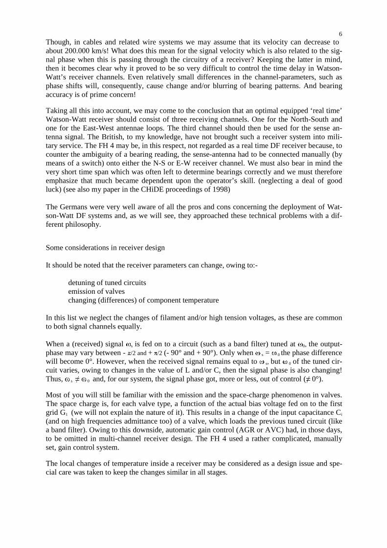
Figure 2:Wächtler’s 3 channels Watson-Watt receiver concept The N-S and the E-W receiver channels may be comparable with those used in regular Watson-Watt direction finders. But the third channel, placed in the centre of the drawing, is exactly equal to the two adjacent ones though, fed now with the sense aerial. As was, more or less, done in the
8 FH 4 circuitry, it was ultimately feeding the Wehnelt cylinder circuitry so as to create the bear-ing pointer at the CRT screen (blanking one segment of the painted bearing pattern). Please note that contrary to the practise with aural direction finding, where a minimal signal strength was deployed, the Watson-Watt direction finders used (for practical reasons) the maxi-mum signal strength (Sum) component so as to paint a bearing pointer (pattern) on the screen of a CRT. The introduction of an additional third receiving (sense) channel seems to be a good solution but, without special precautions the entire DF system would become (most likely) totally unreliable and inaccurate! Let us consider the next figure
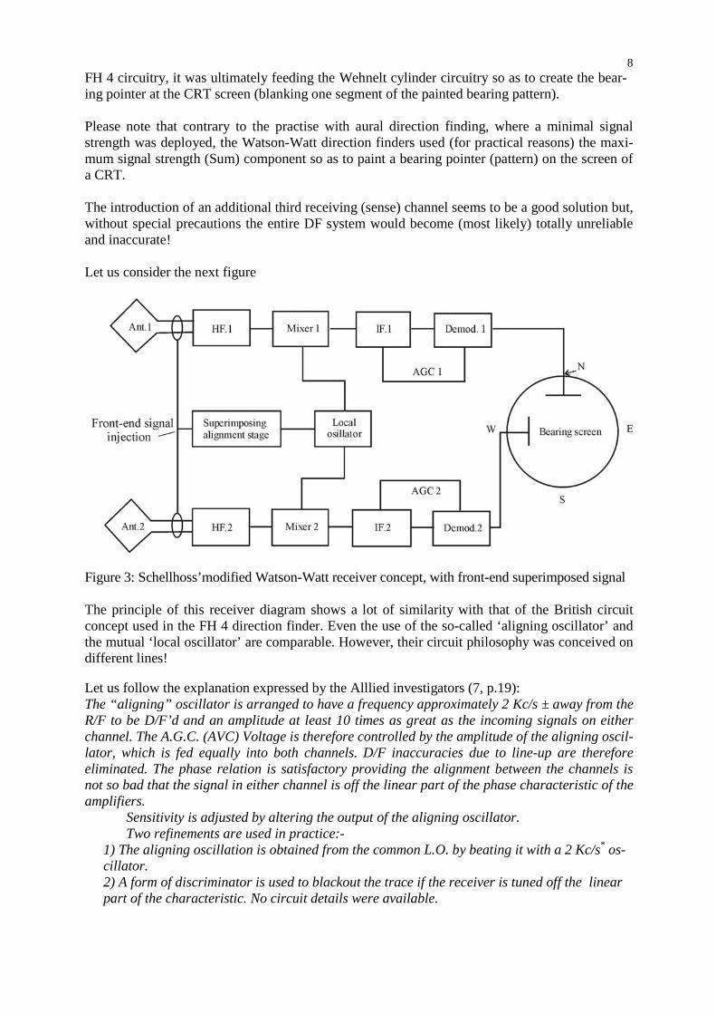
Figure 3: Schellhoss’modified Watson-Watt receiver concept, with front-end superimposed signal The principle of this receiver diagram shows a lot of similarity with that of the British circuit concept used in the FH 4 direction finder. Even the use of the so-called ‘aligning oscillator’ and the mutual ‘local oscillator’ are comparable. However, their circuit philosophy was conceived on different lines! Let us follow the explanation expressed by the Alllied investigators (7, p.19): The “aligning” oscillator is arranged to have a frequency approximately 2 Kc/s ± away from the R/F to be D/F’d and an amplitude at least 10 times as great as the incoming signals on either channel. The A.G.C. (AVC) Voltage is therefore controlled by the amplitude of the aligning oscil-lator, which is fed equally into both channels. D/F inaccuracies due to line-up are therefore eliminated. The phase relation is satisfactory providing the alignment between the channels is not so bad that the signal in either channel is off the linear part of the phase characteristic of the amplifiers. Sensitivity is adjusted by altering the output of the aligning oscillator. Two refinements are used in practice:-
1) The aligning oscillation is obtained from the common L.O. by beating it with a 2 Kc/s* os-cillator. 2) A form of discriminator is used to blackout the trace if the receiver is tuned off the linear part of the characteristic. No circuit details were available.
9 * according to reference (6,p.130) they used 1 kHz beat frequency off-set. Figure 3 and the related latter circuit concept was utilized in several kinds of German DF receiv-ing systems. The N-S and E-W receiver concept, shown in figure 2, shows similarity to that of figure 3. And the alignment-signal had to be fed onto the third (sense) channel too. The investi-gators, who did their job just in the aftermath of the war were, presumably, not aware of the exis-tence of German related references such as (6), (8), and (9). The Allied investigators had not, among other things, mentioned the disturbing effects of space charge and its implications on Ci and admittance which loaded the input circuitry of the valve stages. These disadvantages played an important role in the design of the British FH 4 receiver. However, by now, the Germans had overcome these drawbacks and were able to introduce AGC in the circuitry. Such an AGC (AVC) feature was impossible within the FH 4 receiver concept! One of the most striking technical details was that the tuning capacitor consisted of eleven ganged sections which had to be mutually aligned to within 0.25 % tolerance! The audio signals (LF) of the three receiver channels could also be linked with a separate LF (audio) goniometer apparatus, so as to obtain more accurate bearings. It is evident, that this fea-ture could be a convenient asset when one had to deal with relatively weak and, for instance, blurring signals. Consequently, it became possible to compare the aural bearing with the trace (pointer) on the CRT screen. (6, p.130) The ‘Lichtbild’ apparatus (sometimes known as ‘Lichtkohle’, ‘Lichtbild-Kurzwelle”) was devel-oped in cooperation between NVK and the Army Wa Prüf 7 and was manufactured by the com-pany Schwarzer & Co. Although, according to other sources (10)(11,p,110), it was produced by the company Thomsen & Schwarzkopf in Kiel. The Army’s nomenclature was: Fu.P.E. c2. The principal inventor was Dr. Hans Schellhoss (1905-1978) who was engaged with WaPrüf 7 (Army Ordinance Services section 7). During my recent research on this subject I found one of Schellhoss’ related German patents data (877 046) in which he claimed: Substitution method to measure Phase and Amplitudes. (Substi-tutionsverfahren zur Phasen- und Amplitudenmessung). As for most of German patent applica-tions, their claims and descriptions were expressed in a rather fussy manner! Very curiously, the application date is not clear, as this patent (claim) commenced on 3 August 1950. Yet, I know for a fact that the number series 877xxx dates back to about 1940 to 1944. However, his 1950 patent ‘claims’ show some slightly different technology (approach) and, it is clear that it covered his wartime considerations. We may judge that Schellhoss was, at sometime, involved with the German armed forces and that he, consequently, could not then apply for a patent in his own name. I would like to consider Schellhoss’ wartime invention a:- front-end superimposing technology. As far as we know, only one (or two) prototype(s) of the three-channel receiver came into ser-vice at the interception station in Wilhelmshaven-Sengwarden, two months before the war ended. But it was destroyed, inclusive of all accompanying documentation, just in the final days of the war. Anyhow, not all references quote the same figures. The receiver was designed for the wave range of 1,4 to 16,1 MHz according to (11, p.108-111) or 1,5 MHz to 14 MHz after (6, p. 130). Its frequency range was divided in to 6 bands. The development of this set took, presumably, several years as it had already been the subject of discussion in Spring 1943.
10
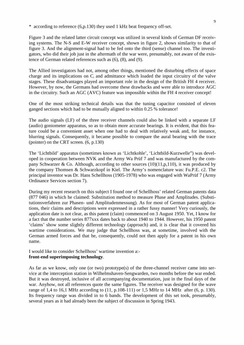
Figure 4: The prototype of Wächtler’s and Schellhoss’ ”Lichtbild-Kurzwelle” DF receiver This photograph shows the exterior of the prototype (1943?) of the three-channel ‘Watson-Watt’ receiver. It is housed in a typical Army box. It is interesting that the test switch ‘T’ shows 16 valve (Röhre) positions though, I could count on the photograph (Figure 5 shown below) 32 valves! Each receiver channel utilized 9 valves (the sense channel ‘S’ used one valve less). The compartment or section ‘L’ houses the first oscillator stage (LO) and the buffer and IF beat-oscillator (aligning-oscillator) and the blanking circuit for the cathode ray tube (CRT). The test-switch was, presumably, used in a double function (2 x 16 = 32), because only 16 emission-check-positions are visible. It is most likely that 12 volt filaments were being used. The CRT type is not known to me though, a commercial type could have been adopted notwithstanding that it had to be rather sensitive with a screen diameter of about 12 cm, being very compact and with a very short glass envelope as well. The German Army often insisted on the use of battery valves, due to their mobile requirements. But, if we look at the block-diagram in figure 3 (9 valves per receiver channel), then we may presume that every stage required, necessarily, opti-mal amplification. And, most likely, the valve type RV 12 P 2000 (static µ = 2000) and/or RV 12 P 2001 (µ is variable < 2000) was utilised. On the next page we see the rather compact interior of the receiver block, as viewed from the top.

11
Figure 5: The interior (top-view) of the Lichtbild-Kurzwelle prototype If we consider that the diameter of the valve base of the RV 12 P 2000 is 2.5 cm, then we may estimate that the receiver frame is about 50 cm wide. That its height is about 40 cm and that the receiver block is about 40 cm deep. These are the dimensions for the (die cast?) chassis with the odd extra cm to give the outside diameter of the box itself. Transient signals To record and measure short lasting phenomena, the Germans (Schellhoss?) created a magnetic recording device. Basically, it consisted of two or three metal discs which were stopped from rotation by a brake and clutch system. When a signal appeared (presumably triggering a thresh-old) then the disc rotated for 1/50 of a second and stopped automatically after one rotation. It was now possible to read-out, simultaneously, the content of the magnetic discs as often as may be required (6, p. 127-130) Wullenwever Regular naval DF systems were, to some extent, satisfying the demands of the German Naval organisations. But, as we know, the German navy was operating in most Oceans. Between Bar-entz Sea (called after the Dutch captain Willem Barentz) all the way down south of Capetown and in the Indian Ocean into the Strait of Malacca (Penang) up to Japan, although very rarely in the Pacific. This engendered an increasing demand for ultra sensitive and selective DF systems. How could they satisfy this demand? Normal systems could barely be improved and, after due considerations, the NVK decided to cooperate with Telefunken specialists and drew up a set of objectives.

12 They contemplated phase measuring technologies, which had the disadvantages that they were frequency dependent. However, a delay-line, when correctly adapted to a receiving array, is fre-quency independent. This is even true for acoustical arrays! (See also my contribution on Sonar in the CHiDE proceedings of 1996, also available on our website) One of the greatest in this sci-entific field was Stenzel. But, let us first follow the course of the considerations. The British FH 4 HF/DF receiver was, on board ships, used in conjunction with loop-antennas and could only supply proper bearings when it received so-called ground-waves. These are sig-nals received from less than about 30 miles (at sea), in which the signal arrives in a straight line from the transmitting source. Long distance signals, may not be properly received by those loop-antennas. The occurrence of ground and sky waves at the same time, may cause polarisation er-rors of up to 90°! (12, P.1) This is why shore based DF stations were maintaining Adcock an-tenna systems which, in contrast, are adequate for receiving sky-waves. One of the most hampering phenomena regarding DF, generally, is the occurrence of both ground and sky waves at the antenna. Without, very sophisticated precautions (which were prac-tically impossible in those days), DF becomes most unreliable! Consequently, speaking in gen-eral terms, vertical radiators are most suitable for the reception of sky-waves (by way of the ionosphere) whereas loop antennas are more favoured for ground wave reception. There are several ways to increase the directivity of antenna arrays. One option is to use a straight-line array of vertical radiators which has to be fed in phase and, with a reflecting circum-ference behind the perimeter of the aerial system. To obtain the optimal radiation patterns one has to compensate for the travelling time of the electrical signals in the directional system. This results, inevitably, in the appearance of more or less uncontrollable side lobes. Unfortunately these are very frequency dependent too. (see my CHiDE sonar contribution of 1996) Stenzel worked out these phenomena mathematically, and he has introduced a so-called delay-line compensator in conjunction with sonar technology. It can be proved that when such a delay-line is properly designed that it acts independent of frequency.
Figure 6: Overhead view of a Wullenwever site

13 This figure shows the top view of a Wullenwever site. The North-South antenna aerials were exactly placed on a North-South meridian so to obtain true geographical bearings. According to (12, p.29) this was at: 57° 28' 39'' North and the E-W aerials at: 10° 20' 04'' West. These coor-dinates were pointing at the central pointer of Stenzel’s Sine-Compensator. The forty vertical radiators (aerials) are placed on the arc of a circle with a diameter of 120 m. Thus, 10 antenna’s may be considered in every quadrant. The (flat) reflector walls (iron wires) are spaced a ¼ λ away from each vertical radiator (aerial), computed for the highest frequency deployed. They were erected at the circumference of the circle with spacing between two adja-cent radiators kept to ½ λ for the shortest wave length which had to be considered. The Wullenwever antenna-system was designed and calculated by Rothe and Kotowski (Tele-funken). It is clear that the impedance at the feeding point, over the applied frequency range of the radia-tors, had to be kept ‘real’ and the imaginary components to be as low as possible (Zant . R
T).
Let us now consider one of the forty vertical radiator elements in the Wullenwever array as illus-trated in Figure 7 below.
Figure 7: Wullenwever “Reusen-antenna” and its antenna impedance Zant (sizes in metres) This antenna type had been regarded, in Germany, as a wide band vertical radiator known as “Reusen-Antenne”, (according to 12, p.12) ...a vertical cylindrical cage tapering at both ends to the form of a cone built around a wooden scaffolding structure...). The top loading (Dachka-pazität), was connected onto the Reuse radiator by a 166 ohm resistor and the circuitry had to compensate for the capacitive component of the matching impedance at frequencies below ¼ 8 (.17 MHz). According to (13, p.122), the antenna impedance Zant, varied at its feeding point for the frequencies of 8.5 MHz up to 17.5 MHz (about 1 octave), between 52 and 65 ohm (though, this plot made < March 1943 shows for RT slightly different figures, but 13 p.122 refers to 1944/45 data. The impedance plot shows the correlation between Rbl = X and R
T in the frequency
domain. The optimal working conditions were being obtained within the dotted circle. These
14 antenna impedance figures allowed, without complicating mis-match, direct connection onto the coaxial cables which had, of course, to be of exactly equal lengths. However, the Wullenwever at Skisby (in German literature referred at Hjörring) was designed to cover the frequency range of 6-20 MHz. But the previous figures illustrated the optimal (best) frequency range of the Wullenwever installation. It is clear that we can magnify the antenna gain when we consider the induced electro magnetic forces in the adjacent antenna group radiators as well. But, these are placed, as shown in figure 6 on the arc of a circle.
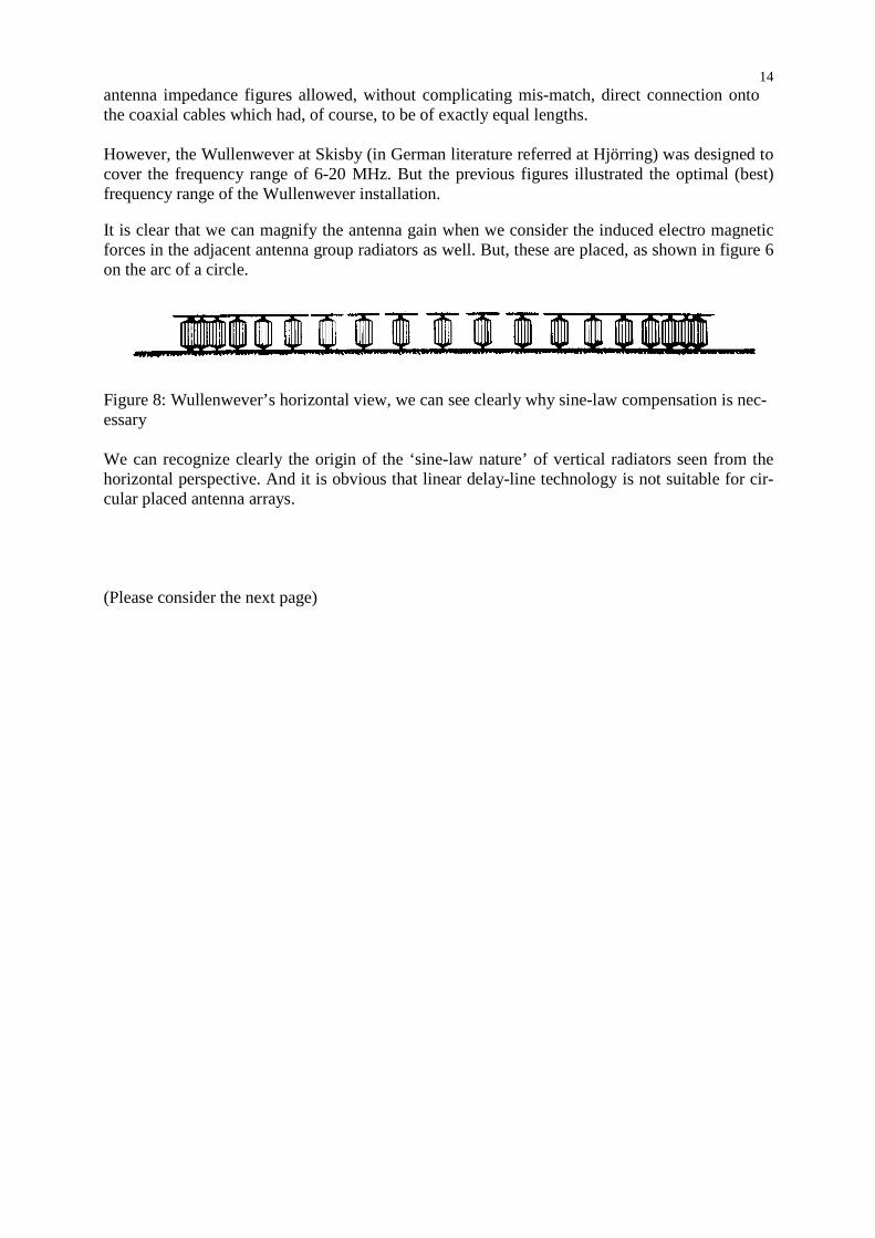
Figure 8: Wullenwever’s horizontal view, we can see clearly why sine-law compensation is nec-essary We can recognize clearly the origin of the ‘sine-law nature’ of vertical radiators seen from the horizontal perspective. And it is obvious that linear delay-line technology is not suitable for cir-cular placed antenna arrays. (Please consider the next page)

15
Figure 9: Stenzel’s sine-compensator concept Following the line of P.G. Redgment’s description (12, p.15): As already mentioned the elements of the delay networks were unequal and, in fact, varied in a manner obeying a sine-law so as to take into account the fact that the individual aerials were placed on the arc of a circle and so as to produce in-phase output voltages for radiation incident along the axis of symmetry of the operative sector. The function of the two delay networks in the goniometer (in German ‘Kompensator’,AOB) was to derive from each aerial array of the operative sector signals equivalent to those which would be obtained from identical flat, co-planar arrays orientated normally to the incident signal (wave, AOB) Explanation of the symbols used in Stenzel’s Compensator (figure 9). A = Axis of symmetry, bearing pointer C = Capacitive coupling device R = Matching resistors, equal to the delay-line characteristic impedance S = Sum/Difference selector switch, zero clearing device (12, p.21) These types of antenna arrays create side lobes which could hamper proper bearings. They coun-tered this downside by decreasing the numbers of aerials involved to sectors of ± 4.5 ° (around the axis of symmetry). Thus, prevented the bordering antennas from supplying their additional
16 (unwanted) EMFs onto the compensator system. To obtain the correct (best) bearing, the switch ‘S’ had to be set for receiving signal-minima. Consequently, the signal ‘null’ will be equal to the axis of symmetry axis of the compensator system. The coaxial cables connected on to the compensator (goniometer) were each loaded with phase correcting circuits, which also acted as step-up transformers, before these were linked on to the capacitive contacts ‘C’. Special provisions were made to facilitate the operation of the Wullenwever direction finding installation. The system had provisions to connect all antenna signals in parallel so as to create omni-directional reception. When special provisions were made, such as amplifiers in each of the forty antenna cables, it was then also technically possible to deploy (independently) more than one compensator system. Thus, at the same time bearings at several frequencies could be obtained from the same antenna installation. (this feature was not actually deployed by the Germans though the post war US systems did employ these features!) (14, p.128-152 ) A major disadvantage of fixed DF arrays is, the dependence on elevation errors caused by the incident wave front. This disadvantage was, more or less, overcome by the Wullenwever com-pensator concept. Assuming of course that the delay-line system has been designed properly, and the bearing pointer is equal with the virtual axis of symmetry of the compensator. If a down com-ing sky wave is approaching the vertical radiators at an elevation angle , then all aerials con-cerned will receive these incidence waves with the same elevation angle . Consider also figure 6. When we use on this occasion the null mode then, the axis of symmetry will point in the direc-tion just in between the two equal antenna groups g1 and g2. Hence, Wullenwever systems be-came less affected by elevation errors than most other DF installations. Advantages of the Wullenwever concept Let us follow the line as it had been expressed in the ASRE Monograph (12, p.3) An effort to obtain higher accuracy led to the technique (adopted by the Admiralty during the recent war) of constructing Adcock Shore-Station Groups for H.F. work. The underlying princi-ple of groups was to “probe’ at several points with U-Adcock direction-finders a reasonably wide sample of incident wave-front and to average the bearings obtained simultaneously upon the several members of the group. ....... In the Groups the direction-finders were located in a cluster, close enough to be treated as a single point for plotting purposes, but at mutual dis-tances of several wavelengths considered great enough to ensure complete randomness (between individuals) of the errors arising from the other important contributory causes (rapidly fluctuat-ing wave-interference errors and polarisation errors) The British considered ten DF stations, as one group. And their optimal bearing accuracy was obtained by considering all ten bearing results.

17
Fig 10: Wullenwever versus Adcock, with respect to their minimum (null) aperture at 15.95 MHz Shown in this figure is the bearing aperture of Wullenwever versus Adcock direction finders, measured at a wave-length of 18.8 m (15.95 MHz). If we compare the sharpness of bearings at system ‘null’ for Adcock and Wullenwever, then the advantages of Wullenwever over regular Adcock DF systems is evident. What is also striking is the amplitude-difference of the received signals just outside the bearing null. These figures gives a good impression of the signal output of both Wullenwever and Adcock antenna installations. The symbol M shows the case in which the DF selector has been switched in at the signal maximum mode (Sum). According to Rind-fleisch, who was involved in Wullenwever development for the NVK, the signal output could optimally (theoretically) be increased by a factor 32 (compared with U-Adcock). Though, for increasing wave length, these figures will, of course, decrease. (13, p.121) According to Redgment in their “General Observations and Conclusion” chapter (12, p.50). (re-sulting from investigations over a considerable time-span) ... It may be remarked that considerable practice appeared to be necessary to acquire familiarity with the high slope of the “Difference” pattern in the vicinity of the null. Further observations a few lines later:- Insofar as the performance data permits a direct comparison of Wullenweber with a standard Adcock (or an Adcock Group) it is possible to draw the following inferences:- Wullenweber is approximately ten times more sensitive than a standard Adcock. It was considered by the Ger-mans to have a sensitivity as high as could be usefully employed. The system seems inherently to have less polarisation error than an Adcock system. On page 51:- The overall conclusion, as regards accuracy, appears to be that a Wullenweber is likely to give a performance rather similar to a spaced group of three or four normal Adcocks, all of which ob-tain bearings on all signals, but no definite performance predictions can be made....
18 Reflection We have followed the course of some aspects of German Naval Communication Research as these were carried out under the supervision of NVK and, its predecessor, NVA. When I started to consider which subjects would be of interest, it duly became clear to me that the interception of naval signals had an important role to play for all belligerents. Much attention had been paid to what happened on the Allied side, but little to what occurred on the Axis side? These aspects were mostly neglected, as being either not of interest or, dealt with as “not being invented here”. One of the striking shortcomings of post war Anglo-Saxon historians is, in my opinion, that they (with only a few exceptions) lost the sense for historically ‘judging the bal-ance’. As we know now, Radar had not been solely invented in Britain, although, one of the aspects of radar was created in Britain after the mid 1930s. Most important was, that the work of all the people involved could be co-ordinated, so that a workable system was in place when it was so desperately needed! Radar was invented and created, simultaneously, in many other developed countries. German off-shore radar systems never became a real threat for their enemies. But, the German air force (GAF) gun-laying (GL) radar systems were regarded by the Allies as being most dangerous. To some extent the same is happening with the history on HF/DF culminating in the bearings taken on German submarines when they communicated with their home stations. A question arises were the Germans able to take bearings on Allied signal sources and, if so, how did they approach this task? Watson-Watt’s contribution in the field of direction finding in the 1920s, paved the way for real-time direction finding. But, the necessity of strictly controlled system parameters hampered its application in the fields of high-frequency direction-finding. As we have seen, the Germans ap-proached the technical difficulties, to some extent, on comparable lines to the British. Schellhoss’ front-end superimposing technology was, in my opinion, a genuine approach which, appears to have been rejected in post war years. We have seen examples as to how the German military requirements had been realised in the form of the “Lichtbild” apparatus. One of the values of this review is, to highlight Schellhoss’ ingenious solution so as to keep the align-ment of the three receiver channels constantly controlled. It can be, mathematically proven, that his ideas should work, but if it was a feasible operational procedure is not known to me. Wächtler established, in the post war years, the C. Plath GmbH which became, ultimately, very famous for their reliable three-channel Watson-Watt receiver concept which was widely em-ployed in naval environments. Many of his NVK colleagues became involved for awhile (some of them even for the rest of their career) in Wächtler’s company. The Wullenwever concept was, the best that was achieved in those days. Nothing, comparable was available in the rest of the world! The Americans soon adopted it widely and they even gave it a similar system name! In particular the Sylvania company became involved and improved the system parameters and widened its frequency range. Rolf Wundt, who was working for Lorenz in the DF fields during the war years, later became senior scientist of Sylvania’s Wullenwever project. It was also possible instead of using for reception to use the antenna array as a direc-tional transmitting source. (14, p.128-152)(strangely they used the word Wullenweber instead of Wullenwever)
19 Final thoughts What happened technically during wartime years in Germany had much to do with the typical German attitudes. Systems had been introduced, often because senior politicians had been dedi-cated to some aspect of technology. And we must not underestimate the political impact of deci-sion making. Unlike the developments of the so-called ‘V’ weapons, where personal interven-tions by the head of state provided funding for intensive work programmes, the NVK projects were, in this respect, of a much less political nature. Nonetheless, the Wullenwever project de-manded considerable efforts. The Germans tended, in those days, to extravagant projects. It is a fact that, though they have been reluctant to admit it, Britain, America + Russia were not slow to latch on to and utilise German developments and, the Wullenwever concept was one of the de-velopments which were widely adopted. We have quoted:- Hülsmeyer, Kühnhold, Erbsloh and von Willisen, Wächtler, Schellhoss, Rothe and Kotowski, Rindfleisch, P.G. Redgment and others who played their role in this brief retro-spect. Acknowledgements I have to thank, late Fritz Trenkle, who, over the years passed so much information on to me. Jürgen Wächtler, who kept his father’s archives and who gave me full access to all he had avail-able. He allowed me to copy very rare wartime papers (military proceedings) and who, kindly, when questions were raised, contacted still living eyewitnesses. Tom Going who showed me, years ago, how and where to look for Allied post war reports. Ian Carter of the Science Museum Library, who allowed us to research their archives in an un-conventional manner. Peter Brinken-berg (Holland), who gave me access to his intriguing library. Bob Guerney (Canada) who sup-plied me with interesting information. And, of course, my friend Richard Walker, without his indispensable support this paper would never have seen daylight. References (1) Jürgen Wächler’s e-mail 15 May 2002 (2) Telephone conversation with Harry von Kroge, on 17 may 2002, concerning: Gema,
Kühnhold, Pelzerhaken, Hollmann’s Barkhausen-Kurz generator valves, German Brems-feld-röhre. To some extent I relied upon the German version of Harry von Krogge’s book who’s English title is “GEMA: Birthplace of German Radar and Sonar”.
(3) Personal letter and papers of the NVK comrade association, O. Köhler, of 19 December 1969; our archives number Z 1021/ ZR 1005
(4) Jahrbuch für Heimatkunde, Jahrgang 2001, J.H. Koch, Geschichtliches über Pelzerhaken Teil II, p. 133 - 160
(5) An Instantaneous Direct-Reading Radiometer, By R.A. Watson Watt and J.F. Herd, (Communicated by permission of the Research Board), (read before the Wireless Section 3 rd March 1926), p. 611-622; The Journal of The Institution of Electrical Engineers Vol. 64 May 1926 No. 353
(6) Sammlung der Vorträge anlässlich der Arbeitstagung, “Navigation”, 23 - 24 March 1944, at the Ferdinand-Braun-Institut Landsberg/Lech, BHF Arbeitskreis Naviagtion; Dr. Rind-fleisch personal wartime copy; our archives number Z 2174a / ZR 402
(7) CIOS Report XXXI-38; our archives number Z 1742/2, ZR 1633a / VK 1593
20 (8) Navy Conference (Marine-Tagung, 9-10 March 1944, our archives number Z 299 / ZR
403 (9) Ausgewählte Fragen über Theorie und Technik von Antennen, Tagung (Secret Confer-
ence) 24-26 March 1943, ZWB (Zentrale für wissenschaftliche Berichtwesen) volume 1 and 2; copy available in our archives, but has not yet got a registration number
(10) E-mail message by Jürgen Wächtler, of 28 May 2002 (11) Die deutschen Funkpeil- und -Horch-Verfahren bis 1945, Fritz Trenkle, published in co-
operation with AEG-Telefunken, 1982, ISBN 3-87087-129-6 (12) A.S.R.E Monograph 806; THE WULLENWEBER, THE THEORY, DESIGN AND EX-
PERIMENTAL INVESTIGATION OF THE EX-GERMAN WIDE-APERTURE H.F.D.F. WULLENWEBER AT SKISBY, NORTH JUTLAND, DENMARK, by A.H. Mugridge and P.G. Redgment; Admiralty Signal & Radar Establishment, September 1949; ACSIL/ADM/49/691; copy available in our archives, but has not yet got a registra-tion number.
(13) Die Großbasis-Peilanlage “Wullenwever”, Hans Rindfleisch, NTZ March 1956, page 119-123, based upon Rindfleisch contribution on to (9) conference.
(14) R. Wundt, Signal Processing Arrays, Agard Conference Proceedings No.16, 1968 (Li-brary of Congress Catalog Card No. 67-22237); pages 128-152