naval postgraduate school - apps.dtic.mil · ad-a256 701 naval postgraduate school monterey,...
TRANSCRIPT
AD-A256 701
NAVAL POSTGRADUATE SCHOOLMonterey, California
0 DTI0 ELL[cTit/
THESISTHE DEFENSE MESSAGE SYSTEM
ANDTHE U.S. COAST GUARD
by
John J. Lapke
June 1992
Principal Advisor: Dan C. Boger
Approved for public release; distribution is unlimited
92-28649I/~l JH [Jil 11111 llll h JIJJi Jm JfJi JJJ JJJ

UnclassifiedSECURITY CLASSIFICATION OF THIS PAGE
REPORT DOCUMENTATION PAGEla. REPORT SECURITY CLASSIFICATION 1 b. RESTRICTIVE MARKINGS
Unclassified
2a. SECURITY CLASSIFICATION AUTHORITY 3. DISTRIBUTION/AVAILABILITY OF REPORT
Approved for public release; distribution is unlimited.2b. DECLASSIFICATIONIDOWNGRADING SCHEDULE
4. PERFORMING ORGANIZATION REPORT NUMBER(S) S. MONITORING ORGANIZATION REPORT NUMBER(S)
6a. NAME OF PERFORMING ORGANIZATION 6b. OFFICE SYMBOL 7a. NAME OF MONITORING ORGANIZATIONNaval Postgraduate School (If applicable) Naval Postgraduate School
32
6c. ADDRESS (City, State, and ZIP Code) 7b. ADDRESS (City, State, andZIP Code)
Monterey, CA 93943-5000 Monterey, CA 93943-5000
8a. NAME OF FUNDINGiSPONSORING 8b. OFFICE SYMBOL 9. PROCUREMENT INSTRUMENT IDENTIFICATION NUMBERORGANIZATION (If applicable)
8c. ADDRESS (City, State, and ZIP Code) 10. SOURCE OF FUNDING NUMBERS
Program Ekement No PFrOKt NO I ak No Work Unit Accetion
Number
11. TITLE (Include Security Classification)
The Deffense Message System and The U.S. Coast Guard
12. PERSONAL AUTHOR(S) Lapke,JohnJ.
13a. TYPE OF REPORT 13b. TIME COVERED 14. DATE OF REPORT (year, month, day) 15. PAGE COUNTMaster's Thesis From To June 1992 126
16. SUPPLEMENTARY NOTATIONThe views expressed in this thesis are those of the author and do not reflect the official policy or position of the Department of Defense orthe U.S. Government.
17. COSATI CODES 18 SUBJECT TERMS (continue on reverse if necessary and identify by block number)
FIELD GROUP SUBGROUP Defense Message System, U.S. Coast Guard, Coast Guard Telecommunications System,Government Open Systems interfconnection Protocol, Open Systems Interface, CoastGuard Data Network, Meaasage Distribution Terminal
19. ABSTRACT (continue on reverse if necessary and identify by bloc'k n'Irum er)" , oast Guard Data Network, Message Ditribution Terminal
This thesis provides an overview of the Defense Message System (DMS) and the messaging related components of the Coast GuardTelecommunications System (CGTS). Also addressed are the seven-layer Open Systems Interface (OSI) Reference Model, the GovernmentOpen Systems Interconnection Protocol, and various interface devices such as bridges, routers, and gateways. The DMS Program is composedof a baseline architecture and three phases that will result in the transition from baseline systems and networks to a target architecture,with a goal for complete writer-to-reader messaging services. DMS baseline components, such as the Automatic Digital Network andcomponents of the Defense Data Network, will either be phased out or transitioned into new architectures that will lead to the targetarchitecture. The Coast Guard telecommunications organization is addressed as well as the broad aspects of the CGTS. A key issue of thisthesis is to emphasize the importance of interoperability between the DMS and the CGTS through the use of approved standards andprotocols.
20. DISTRIBUTION/AVAILABILITY OF ABSTRACT 21. ABSTRACT SECURITY CLASSIFICATIONM UNCLASSIFIEoUN.IMITED SAME AS REPRT 3DTIC USES Unclassified
22a NAME OF RESPONSIBLE INDIVIDUAL 22b. TELEPHONE (Include Area code) 22c OFFICE SYMBOLDan C. Boger (408)-646-2607/2772 AS/Bo
DD FORM 1473.84 MAR 83 APR edition may be used until exhausted SECURITY CLASSIFICATION OF THIS PAGEAll other editions are obsolete Unclassified
i
Approved for public release; distribution is unlimited.
The Defense Message Systemand
The U.S. Coast Guard
by
John J. LapkeLieutenant Commander, United States Coast Guard
B.S., United States Coast Guard Academy, 1978
Submitted in partial fulfillment
of the requirements for the degree of
MASTER OF SCIENCE IN TELECOMMUNICATIONS SYSYTEMS MANAGEMENT
from the
NAVAL POSTGRADUATE SCHOOL
June 1992
Author: __ _ _ _ _ _ _ _ _ _ _ _ _ _ _ __ _ _ _ _ _ _ _ _ _ _ _ _ _ _
J h Lake
Approved by: / __'ran C. Boger, P nci Il Advisor
Allan WTlloch, Associate Advisor
f V~avid t.Whipple, Chairman/
Department of Administrative Sciences
ii
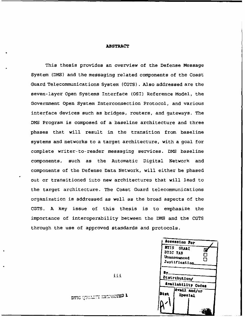
ABSTRACT
This thesis provides an overview of the Defense Message
System (DMS) and the messaging related components of the Coast
Guard Telecommunications System (CGTS). Also addressed are the
seven-layer Open Systems Interface (OSI) Reference Model, the
Government Open System Interconnection Protocol, and various
interface devices such as bridges, routers, and gateways. The
DMS Program is composed of a baseline architecture and three
phases that will result in the transition from baseline
systems and networks to a target architecture, with a goal for
complete writer-to-reader messaging services. DMS baseline
components, such as the Automatic Digital Network and
components of the Defense Data Network, will either be phased
out or transitioned into new architectures that will lead to
the target architecture. The Coast Guard telecommunications
organization is addressed as well as the broad aspects of the
CGTS. A key issue of this thesis is to emphasize the
importance of interoperability between the DMS and the CGTS
through the use of approved standards and protocols.
hAooee.jjelo Fr ...
Dlic VAGRA&IDI Dc TAB 0
:=~Stir catlo
"f"By lt codes
DTICi Davi sCi I" l
__ _ I.

TABLE OF CONTENTS
I. INTRODUCTION ................... 1
A. PURPOSE .................. .................... 1
B. SCOPE .................... ..................... 1
C. APPLICABILITY CONSIDERATIONS ....... ......... 2
1. Statutory Considerations ....... ......... 2
2. Operational and Support Considerations . 3
3. Current Communications Considerations . . 4
D. THESIS ORGANIZATION ............ .............. 5
II. THE DEFENSE MESSAGE SYSTEM .... .............. 6
A. INTRODUCTION ................ ................. 6
B. DMS MESSAGES ................ ................. 7
1. Organizational Messages ........ .......... 7
2. Individual Messages .......... ............ 8
C. OPERATIONAL REQUIREMENTS ......... ........... 8
1. Connectivity/Interoperability .... ....... 8
2. Guaranteed Delivery/Accountability . . .. 9
3. Timely Delivery ............ .............. 9
4. Confidentiality/Security ....... ......... 9
5. Sender Authentication ........ ........... 9
6. Integrity .......... ................. .. 10
7. Survivability ........ ............... .. 10
iv
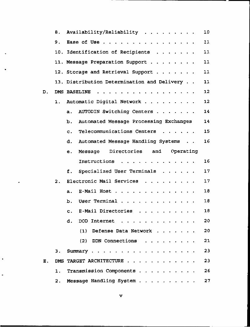
8. Availability/Reliability ....... ......... 10
9. Ease of Use ........ ................ . 11
10. Identification of Recipients .. ....... 11
11. Message Preparation Support ... ........ .. 11
12. Storage and Retrieval Support ......... .. 11
13. Distribution Determination and Delivery . 11
D. DMS BASELINE ........... ................. .. 12
1. Automatic Digital Network ... ......... .. 12
a. AUTODIN Switching Centers ......... .. 14
b. Automated Message Processing Exchanges 14
c. Telecommunications Centers ...... .. 15
d. Automated Message Handling Systems . 16
e. Message Directories and Operating
Instructions ..... ............. 16
f. Specialized User Terminals ...... .. 17
2. Electronic Mail Services ... ......... .. 17
a. E-Mail Host ...... .............. .. 18
b. User Terminal .... ............. .. 18
c. E-Mail Directories ... .......... .. 18
d. DOD Internet ..... ............. .. 20
(1) Defense Data Network ......... .. 20
(2) DDN Connections ... ......... 21
3. Summary .......... .................. .. 23
E. DMS TARGET ARCHITECTURE ...... ............ .. 23
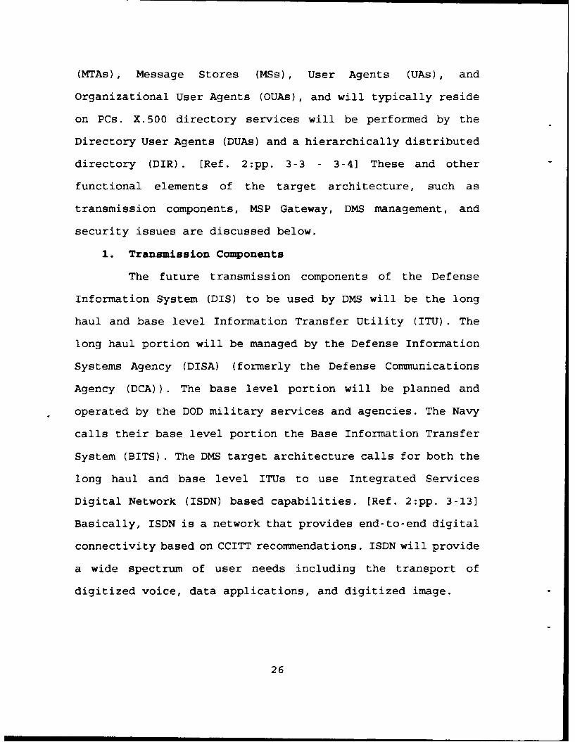
1. Transmission Components .... .......... .. 26
2. Message Handling System .... .......... .. 27
v

3. Directory Services ..... ............ .. 29
4. MSP Gateway ........ ................ .. 31
5. Management ......... ................ 31
6. Security ........... ................. .. 32
F. DMS PHASED IMPLEMENTATION STRATEGY ...... .. 32
1. DMS Phase 1 ........ ................ .. 35
a. TCC Automation ..... ............ .. 35
b. AUTODIN-to-DDN Interface .. ....... .. 35
c. Directory Improvements (MCS and X.500
DIB) ........... ................. .. 37
d. X.400 E-Mail ....... ............. .. 37
e. Open System Interconnection Gateway . 38
2. DMS Phase 2 ........ ................ .. 38
3. DMS Phase 3 ........ ................ .. 43
G. SUMMARY ............ .................... .. 45
III. U.S. COAST GUARD TELECOMMUNICATIONS SYSTEM . . . . 46
A. INTRODUCTION ........... ................. .. 46
B. COAST GUARD TELECOMMUNICATIONS ORGANIZATION 46
1. Commandant/Headquarters Level ......... .. 49
2. Area Command Level ..... ............ .. 50
3. District Command Level ... .......... .. 51
4. Maintenance and Logistics Command Level . 51
5. Headquarters Units ..... ............ .. 52
6. Field Units ........ ................ .. 52
a. Communications Stations ... ........ .. 52
vi

b. Group Offices .... ............. .. 53
C. COAST GUARD TELECOMMUNICATIONS SYSTEM ..... .. 53
1. Definition of the CGTS ... .......... .. 54
2. CGTS Mission ......... ............... .. 54
D. COAST GUARD STANDARD WORKSTATION .. ....... .. 55
1. Automated Message Preparation ......... .. 57
2. Information Transfer Distribution System 57
3. X.25 District Network .... ........... .. 59
4. BTOS OFIS Mail ....... .............. 59
5. X.25 Applications .... ............. .. 59
6. Standard Semi-Automated Message Processing
System ........... .................. 60
7. SORTS Message Writing Utility ......... .. 62
8. Network Security Software ... ......... .. 62
E. NETWORKS AND SYSTEMS ....... ............. .. 63
1. Coast Guard Data Network ... ......... .. 63
2. Automatic Digital Network ... ......... .. 64
a. Message Distribution Terminal ..... .. 66
3. Defense Data Network ..... ........... .. 70
4. Secure Data Network ...... ............ .. 71
5. Federal Telephone System 2000 ......... .. 72
F. FUTURE PLANS ........... ................. .. 72
1. Vision Statement ....... ............. .. 72
2. Initiatives For 1995 Accomplishment . . .. 73
IV. STANDARDS AND INTERFACES ......................... 75
vii

A. STANDARDS . . . . . . . . . . . . . . . . . . . 75
1. Government Open Systems Interconnection
Profile .......... .................. .. 75
2. OSI Reference Model ...... ............ .. 77
a. Physical Layer (Layer 1) ..... ....... 79
b. Data Link Layer (Layer 2) ......... .. 80
c. Network Layer (Layer 3) ... ........ .. 80
d. Transport Layer (Layer 4) ......... .. 81
e. Session Layer (Layer 5) ... ........ .. 81
f. Presentation Layer (Layer 6) ..... 82
g. Application Layer (Layer 7) ........ .. 82
3. GOSIP Version 2 ...... .............. .. 83
a. Architecture ..... ............. .. 83
b. Protocols ........ ............... .. 86
(1) Physical Layer .... .......... .. 87
(2) Data Link Layer .. ......... .. 88
(3) Network Layer ... .......... 88
(4) Transport Layer .. ......... .. 89
(5) Session Layer ... .......... 89
(6) Presentation and Application Layers 89
B. INTERFACE DEVICES ........ ............... .. 90
1. Repeaters .......... ................. .. 90
2. Bridges .......... .................. .. 91
3. Routers .......... .................. .. 92
4. Gateways ........... ................. .. 93
viii

V. SUMMARY AND CONCLUSIONS ........ .............. 97
A. SUMMARY .............. .................... 97
B. ISSUES AND RECOMMENDATIONS ..... .......... 100
1. Plans for the DMS Transition .. ....... . 101
2. Other Specific Issues .... ........... .. 103
a. X.400 MHS and X.500 Directory ..... .. 103
b. DMS-CGTS Interface ... ......... .. 104
c. Security Issues ...... ............ 105
d. Coast Guard Support to DOD . ... ... 105
APPENDIX A. COAST GUARD AUTODIN ACCESS ... ........ 107
APPENDIX B. COAST GUARD DSNET 1 ACCESS .. ...... .... 108
LIST OF REFERENCES ............. .................. 109
INITIAL DISTRIBUTION LIST ........ ............... 112
ix

LIST OF FIGURES
Figure 1. DMS Baseline Architecture ........... 13
Figure 2. DMS Target Architecture ....... ........... .. 25
Figure 3. DMS Message Handling System Functional Model . 28
Figure 4. DMS Directory Services Functional Model . . 30
Figure 5. DMS Implementation Strategy ..... ......... .. 33
Figure 6. DMS Phase 1 Architecture ...... ........... .. 36
Figure 7. Early DMS Phase 2 Architecture .... ........ .. 40
Figure 8. End DMS Phase 2 Architecture .... ......... .. 41
Figure 9. DMS Phase 3 Architecture ...... ........... .. 44
Figure 10. U.S. Coast Guard Organization ... ........ .. 47
Figure 11. U.S. Coast Guard Geographic Boundaries . . . 48
Figure 12. E-Mail Envelope Concept ....... ........... .. 58
Figure 13. CGSW SSAMPS Overview ........ ............. .. 61
Figure 14. Coast Guard Data Network's Future Backbone 65
Figure 15. CG Pacific Area COMMCEN's MDT Connections 68
Figure 16. Message Distribution Terminal (MDT) ..... 69
Figure 17. OSI Reference Model ......... ............. .. 78
Figure 18. GOSIP Version 2 OSI Architecture ... ....... .. 84
Figure 19. Bridge Functionality (using OSI Reference
Model) .............. .................... .. 91
Figure 20. Router Functionality (using OSI Reference
Model) .............. .................... .. 92
x

Figure 21. Gateway Functionality (using OSI Reference
Model) .................................... 94
Figure 22. LAN - Gateway - PSN - Database Network . . . . 95
xi

I. INTRODUCTION
A. PURPOSE
The purpose of this thesis is to examine the Defense
Message System (DMS) and Coast Guard Telecommunications System
(CGTS), and explore how the DMS will affect the CGTS. The
Department of Defense's (DOD's) long term transition from a
DMS Baseline Architecture to the DMS Target Architecture is
planned to occur in a three-phased strategy from 1988 to the
year 2008. Since the Coast Guard uses DOD systems and networks
to deliver and receive messages, the DOD's transition to the
DMS directly impacts the Coast Guard. Therefore, the phased
implementation strategy to the DMS Target Architecture needs
to be fully understood by the Coast Guard, and future changes
to Coast Guard message procedures, systems, and networks need
to be done in collaboration with DOD interoperability efforts.
B. SCOPE
This thesis is designed to provide an overview of the DMS,
the parts of the CGTS that deal with shoreside general service
(GENSER) messages and electronic mail (E-Mail), and the
relationships between them. It is not designed to provide
detailed technical aspects of the electronic aspects of
message transmissions, however, it will address related
systems and networks used.
1
C. APPLICABILITY CONSIDERATIONS
1. Statutory Considerations
The intent of this section is not to imply that the
Coast Guard has direct statutory requirements to be involved
with the DMS target architecture and implementation strategy,
however, a common sense planning and coordination approach to
future events is needed to ensure that there are appropriate
interoperable interfaces between the DMS and the CGTS. Never-
theless, statutory requirements should be understood to ensure
that its intent is accomplish-ýd.
Basic statutory considerations include the fact that
the Coast Guard is a military service and a branch of the
armed forces of the United States. As a military service, the
Coast Guard operates in the Department of Transportation,
except when it is operating as a service in the Department of
the Navy. The Coast Guard may operate in the Department of the
Navy upon declaration of war or when the President so directs
it. [Ref. 1:pp. 35-361 Therefore, the Coast Guard
t el ecommuni cations systems should be interoperable with those
of the Department of the Navy (DON) and, in general, with the
DOD and the National Command Authorities (NCA) . The Coast
Guard has a responsibility to be interoperable with the DMS
(i.e., interoperable with the NCA, DOD, and DON) for present
and future military preparedness and national defense
2

purposes, including U.S. Maritime Defense Zone (MDZ)
responsibilities.
2. Operational and Support Considerations
During day-to-day peacetime operations the Coast Guard
needs to communicate with many different elements of the DOD.
These needs are based on the performance of Coast Guard
missions and support functions related, but not limited, to
the following activities on, under, and over the high seas or
waters subject to U.S. jurisdiction:
"* Federal law enforcement, including U.S. efforts withthe "War on Drugs" and fisheries law enforcement, andrelated intelligence activities.
"* Promotion of safety of life and property, includingsearch and rescue, marine safety, and environmentalprotection.
"* Other special operations and military exercises.
Operational reporting also includes keeping the U.S
Navy and other DOD elements informed of the status and
capability of Coast Guard forces. These message reports
include Casualty Reports (CASREPs), Movement Reports
(MOVREPs), and Status of Resources and Training Systems
(SORTS).
In general, some Coast Guard operations are performed
in cooperation or coordination with various DOD agencies and
elements thereof, and various military operational commanders,
especially naval operational commanders, and their staffs and
3

operational forces. Day to day direct communications and
interoperability are necessary.
Support considerations include inventory control and
supply coordination. The Coast Guard owns or operates Navy
supported equipment. This type of coordination is accomplished
by Coast Guard aviation and ship inventory control points
located at Coast Guard Air Station Elizabeth City, NC, and
Coast Guard Yard, Curtis Bay, MD, respectively. Message
communications requirements at these locations necessitated
connections to the DOD message transport system.
3. Current Communications Considerations
In addition to the operational considerations already
mentioned, the Coast Guard currently uses DOD networks to
transport messages to and from both Coast Guard and DOD
agencies and elements. This consideration is evident with the
connections the Coast Guard has to the DOD's Automatic Digital
Network (AUTODIN). One of the primary uses of this network by
the Coast Guard is for the transport of classified messages.
As will be addressed in the next chapter, the AUTODIN is part
of the DMS baseline. Therefore, the Coast Guard needs to
address what will happen to those connections under the
planned DMS initiatives.
In addition to the Coast Guard's use of DOD systems
and networks, the DOD commands and units use the message
services of the CGTS. One current example is the U.S Pacific
4

Command's Joint Task Force Five (JTF 5). JTF 5 is located at
Coast Guard Island, Alameda, CA, and receives all of its
message services through the Coast Guard Pacific Area's
communications center. This example typifies the mutual
support provided by the Coast Guard to DOD commands/units.
Situations like this create a grey area between the DMS and
the CGTS and highlight the need for coordination.
D. THESIS ORGANIZATION
This thesis is organized into the following chapters.
"* Chapter II addresses the Defense Message System.
"* Chapter III addresses the Coast Guard TelecommunicationsSystem.
"* Chapter IV analyzes DMS-related issues that impact on theCGTS.
"* Chapter V provides a summary and conclusions.
5

II. THE DEFENSE MESSAGE SYSTEM
A. INTRODUCTION
The Defense Message System (DMS) Program is a long-term
transitional approach to improve the Department of Defense's
(DOD's) message communications system and reduce costs while
being responsive to overall mission requirements. Factors that
led to this effort were budgetary constraints, old equipment
and systems that were expensive to maintain and staff, and the
emergence of new standards and technologies. The DMS design is
based on the principles of standardization and
interoperability. [Ref. 2:p. 1-1; Ref. 3:p. 1)
The DMS consists of software and hardware, standards and
procedures, and personnel and facilities involved in providing
DOD message services. Also included are other non-DOD
interfaces to other systems, but DMS does not include those
systems. DMS elements are the policies, procedures, standards,
and components. DMS components are the hardware and software
implementation of message applications. [Ref. 2:pp. 1-1 - 1-21
This chapter addresses various aspects of the DMS,
including a definition of DMS messages, and the guiding
operational requirements for the DMS. Also addressed is an
overview of the DMS Baseline, Target Architecture, and the
three phases that are planned to transition DOD message
6
systems and networks from the Baseline to the Target
Architecture.
B. DMS MESSAGES
A computer dictionary's definition of a message is:
In data communications, a message is an item of data witha specified meaning transmitted over communications lines.A message is composed of a header, the information to beconveyed, and an end-of-message indicator. [Ref. 4:p.222].
Allied Communications Publication (ACP) 167 defines a
message as:
Any thought or idea expressed briefly in plain or secretlanguage, prepared in suitable format form for trans-mission by any means of communication. [Ref. 5:p. 2-42]
From these definitions comes two primary concepts: (1) a
message has information, and (2) the message is transmitted
and/or delivered. In addition, messages are typically
formatted for administrative and transmission purposes. DMS
messages are identified by two message classes, either
organizational or individual [Ref. 2:p. 1-3].
1. Organizational Messages
Organizational messages include command and control
messages exchanged between organizational elements that
require a designated releasing official by the sending
organization. The receiving organization determines its own
internal distribution. This class of message is official in
nature, and the operational requirements that are placed on a
communications system include: non-routine precedence,
7

guaranteed timely delivery, high availability and reliability,
accountability, and survivability. [Ref. 2:p. 1-3] This class
of message directly relates to messages that are commonly
referred to as official record message traffic.
2. Individual Messages
Individual messages include working level and
administrative communications between individuals or end
users, and in general, do not commit or direct an
organization. Communications systems will need to provide
connectivity between individuals and also be user friendly.
[Ref. 2:p. 1-3] This class of message directly relates to
messages that are commonly referred to as electronic mail (E-
Mail), which tend to be less official in nature.
C. OPERATIONAL REQUIREMENTS
The mission of the DMS is to handle messages in a manner
appropriate to their content [Ref. 3:p. 21. The thirteen
primary operational requirements for the DMS are as follows.
Each of these requirements need to be addressed for current
systems and their subsequent improvements or replacements.
1. Connectivity/Interoperability
The DMS is required to provide message services within
the DOD community, and it must also support interfaces to
systems of other U.S. government entities. The concept of
connectivity deals with providing message communications from
writer to reader. Messages should be drafted and released, and
8
transmitted and received as close to the users as possible.
This concept requires the eventual use of international
standards and protocols. [Ref. 3:pp. 3-4]
2. Guaranteed Delivery/Accountability
The DMS is required to deliver messages with a high
degree of certainty, and if non-delivery occurs, then the
system must promptly notify the sender of the situation. Due
to the official nature of organizational messages, writer to
reader accountability is required. [Ref. 3:p. 4]
3. Timely Delivery
This requirement is based on preferential handling of
more urgent messages. The DMS needs to dynamically change to
accomodate varying traffic load patterns. A message's delivery
time should be a function of message precedence and system
stress level. [Ref. 3:p. 5]
4. Confidentiality/Security
This requirement is based on the prevention of
unauthorized access or unauthorized release of information.
The DMS should process, and appropriately separate and
protect, all messages based on classification or
compartmentation. Security requirements are based on
integrity, authentication, and confidentiality. [Ref. 3:p. 5]
5. Sender Authentication
This requirement calls for the unambiguous
verification of the receipt of a message from a specific
9
originating source. The release of an organizational message
must be approved by a competent releasing official. [Ref.
3:p. 5]
6. Integrity
This requirement is based on the concept that the
information content of a message sent by the writer is the
same as is received by the intended reader. If authorized by
the writer, the DMS may make format changes to accommodate the
different component system capabilities. [Ref. 3:p. 5]
7. Survivability
The DMS survivability requirements are directly based
on the survivability of the users of the system, and should
not degrade the survivability of other interfaced systems.
This requirement is accomplished through redundancy,
proliferation of system assets, and distributed processing.
[Ref. 3:p. 6]
8. Availability/Reliability
DMS availability should provide essentially
continuous, all-hours messaging services. This can be
accomplished by obtaining highly reliable, readily
maintainable, and thoroughly tested software and components,
and where appropriate, provide system redundancies and back
ups. [Ref. 3:p. 61
10
9. Ease of Use
In order to provide a system that automates writer to
reader functions, the DMS needs to be flexible and responsive
enough to allow user operations without extensive training.
Developers of replacement components and software packages
should consider ergonomically friendly user interfaces to
facilitate this ease of use requirement. [Ref. 3:p. 6]
10. Identification of Recipients
The identification of recipients is necessary so that
senders can identify to the DMS the final destination of an
organizational or individual message. This is accomplished
through the use of directories. [Ref. 3:pp. 6-7]
11. Message Preparation Support
This support requires user-friendly preparation of
messages in the formats required, such as the U.S. Message
Text Format (USMTF). [Ref. 3:p. 7]
12. Storage and Retrieval Support
After delivery, DMS should support the storage of
messages for later retrieval for readdressal, retransmission,
and automated message handling purposes. The storage period
for organizational messages is specified by allied
communications procedures. [Ref. 2:p. 7]
13. Distribution Determination and Delivery
This last requirement calls for the DMS to determine
the distribution and delivery of organizational and individual
11

messages. For individual messages, delivery is specified by
the message originator. For organizational messages, the DMS
determines the destination for the addressee(s) in the
message, and then delivery is accomplished per the
requirements of the receiving organization. [Ref. 3:pp. 7-81
D. DNS BASELINE
The first step in the DMS transition strategy was to
identify a starting baseline based on the existing situation
in September 1989. From this baseline, the DMS will evolve in
approximately twenty years into a final target architecture
based on requirements to reduce costs and staffing levels,
while maintaining or improving existing levels of service and
security. [Ref. 2: p. 1-11
The importance of identifying the baseline is for the use
of baseline information by the DOD as a fixed reference point
and an evaluation tool against which the future costs,
staffing levels, and performance incurred during the
transition phases can be measured. The initial baseline
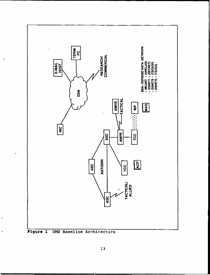
architecture is depicted in Figure 1 [Ref. 2:p. 2-21 . The two
primary components of the DMS baseline are the Automatic
Digital Network and the electronic mail services on the DOD
Internet and DOD local area networks.
1. Automatic Digital Network
The Automatic Digital Network (AUTODIN) transports
messages using store and forward technology, and was
12
C)0 0LU IL
z
No.) a .) V)
i3zzz
400
U
U Ole
04) 0
I-
Figre DM Baelne rchtecur
130

originally established in the 1960s. This DOD network is used
to provide secure, multi-level precedence, and automated
message services to meet DOD operational requirements. [Ref.
2:p. 2-11 As is, the AUTODIN is considered relatively costly
to operate and maintain, and thus is a target for improvement
or replacement under the DMS strategy. [Ref. 3:p. 15] AUTODIN
components are shown in Figu7e 1 and are described below.
AUTODIN equipment connections are accomplished using
dedicated transmission lines that are protected with the use
encryption equipment (e.g., KG-84s) physically located in
secure locations. Tailored AUTODIN interface devises are used
to connect with tactical units, such as Navy afloat commands,
and with allied, commercial and other agencies. [Ref. 2:p.
2-41
a. AUTODIN Switching Centers
AUTODIN Switching Centers (ASCs) provide store and
forward message switching for worldwide coverage. The ten
operational ASCs and the multiple interconnecting links
between them are referred to as the AUTODIN's trunk lines or
backbone. These centers also provide validation functions,
format conversions, and specialized routing functions. [Ref.
2:pp. 2-1, 2-4]
b. Automated Message Processing Exchanges
Automated Message Processing Exchanges (AMPEs) are
connected to the ASCs and provide selected switching
14

functions, conversion of destination plain language addressees
(PLAs) into AUTODIN routing indicators (RIs) (for AUTODIN
backbone use), and message distribution to the
telecommunication centers that are local to the specific
AMPEs. There are over 100 AMPEs that include the following
service/agency created and operated systems:
"* Army's Automated Multi-Media Exchanges (AMMEs)
"* Navy's Local Digital Message Exchanges (LDMXs)
"* Air Force's Automated Message Processing Exchanges(AFAMPEs)
"* National Security Agency's STREAMLINER
"* Defense Intelligence Agency's Communication SupportProcessor (CSP) [Ref. 2:pp. 2-2 - 2-3]
The Navy's Naval Co-'nuaications Processing and Routing
System (NAVCOMPARS) is a tailored AUTODIN Interface Terminal
(AIT) that connects to an ASC as a fleet gateway. The
NAVCOMPARS emphasis is to automate the message receipt,
processing, and transmission functions required to support the
fleet. [Ref. 6:p. 3-301
c. Telecommunications Centers
Telecommunication Centers (TCCs) are
administrative message centers that are the primary entry and
exit points for AUTODIN messages. These centers have
historically provided a human-to-human interface via an over-
the-counter operation. TCCs are staffed by communications
15

personnel who typically support one or more organizations, and
these organizations usually have a relatively large volume of
messages that require an appropriate distribution. Over the
years, this operation has become more automated through the
use of optical character readers, the use of hand-carried
floppy diskettes, and in some locations, the use of direct
electrical connections used to deliver and receive messages in
electronic form (versus hard copy printout) with the use of
personal computers (PCs). [Ref. 2:pp. 2-3 - 2-4]
d. Automated Message Handling Systems
These systems automate the TCC's handling of
messages and, in effect, bypass the TCC's traditional
operation and create direct connections to the AMPEs. This
automated processing provides assistance in the coordination,
release and distribution of messages, and the storage,
sorting, and retrieving of messages after receipt. [Ref. 2:p.
2-3]
e. Message Directories and Operating Instructions
Message Address Directory (MAD) lists the Plain
Language Addressees (PLAs) of organizations. The Allied
Communications Publication (ACP) 117 series contains AUTODIN
routing indicators (RIs) for the PLAs. Operating instructions
are disseminated in ACPs and in the Joint Army Navy Air Force
Publication (JANAP) 128. [Ref. 2:pp. 2-1 - 2-3] The ACP and
MAD boxes in Figure 1 are not directly connected to other
16

AUTODIN components because they represent publications and
listings, which are typically printed and distributed as paper
products.
f. Specialized User Terminals
AUTODIN has a number of user terminals that
typically support one organization. They are called user
terminals because they are typically, although not
exclusively, operated by the users, versus the equipment
operated by communications personnel in a full TCC. These
types of terminals usually handle a limited volume of
messages, where there is limited distribution, and therefore
do not require expensive or high speed transmission equipment.
These terminals can be connected to the ASCs or the AMPEs.
[Ref. 2:p. 2-4] The Navy's specialized user terminals are used
in smaller Navy TCCs, and include the Standard Remote Terminal
(SRT) and the Remote Information Exchange Terminal (RIXT).
2. Electronic Mail Services
E-Mail services are typically provided over the DOD
Internet, which is described below. In general, E-mail
services provide a person-to-person message service. When a
message is received, it can be read, printed, and moved for
storage or deleted. In addition to these mail services, the
Internet also provides a File Transfer Protocol (FTP) and
remote login between host computers (TELNET) capabilities.
17
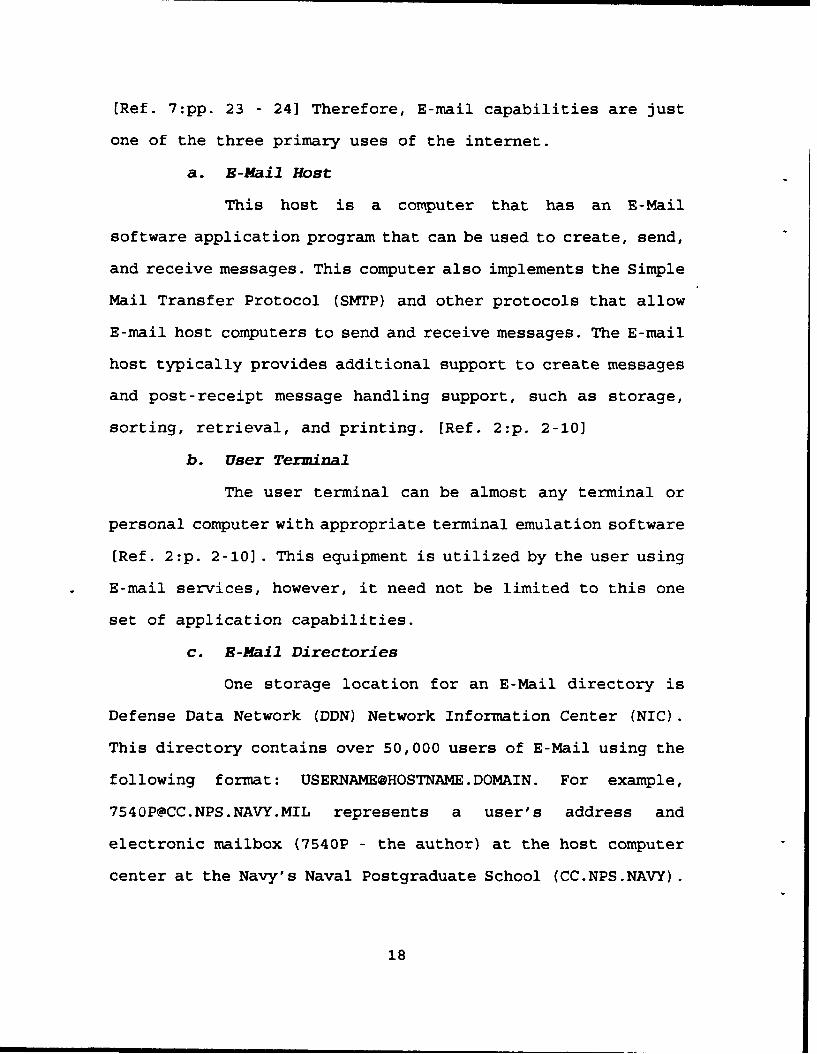
[Ref. 7:pp. 23 - 24] Therefore, E-mail capabilities are just
one of the three primary uses of the internet.
a. E-Mail Host
This host is a computer that has an E-Mail
software application program that can be used to create, send,
and receive messages. This computer also implements the Simple
Mail Transfer Protocol (SMTP) and other protocols that allow
E-mail host computers to send and receive messages. The E-mail
host typically provides additional support to create messages
and post-receipt message handling support, such as storage,
sorting, retrieval, and printing. [Ref. 2:p. 2-10]
b. User Terminal
The user terminal can be almost any terminal or
personal computer with appropriate terminal emulation software
[Ref. 2:p. 2-10]. This equipment is utilized by the user using
E-mail services, however, it need not be limited to this one
set of application capabilities.
c. E-Mail Directories
One storage location for an E-Mail directory is
Defense Data Network (DDN) Network Information Center (NIC).
This directory contains over 50,000 users of E-Mail using the
following format: [email protected]. For example,
[email protected] represents a user's address and
electronic mailbox (7540P - the author) at the host computer
center at the Navy's Naval Postgraduate School (CC.NPS.NAVY).
18
The "MIL" stands for the domain "military agencies and
organizations." Other top-level domains include commercial
institutions (COM), educational institutions (EDU), network
backbone entities (NET), and not-for-profit institutions
(ORG). [Ref. 2:p. 2-10, Ref. 7:p. 59]
The above user's address is not listed at NIC
because the NIC does not maintain a universal directory of
network users. The task of maintaining a centralized listing
of all current network users is too colossal. The NIC
therefore maintains a directory, a host file table which
contains host names registered at the NIC, and the host's
corresponding Internet addresses which consist of four decimal
numbers. These four numbers are separated by a period or a
dot. One example is the DDN.NIC.MIL host at the Internet
address 192.112.36.5. The NIC host file table is transferred
by each host site to their location for E-mail routing
purposes. [Ref. 2:p. 2-10; Ref. 7:pp. 38, 58, 71]
The task of efficiently maintaining a centralized
table of the large number of Internet hosts is difficult, and
it is also difficult for host sites to transfer this
information. Another alternative created was the Domain Name
System (DNS). In the DNS, the host Internet addresses are
grouped into a hierarchy of authority. This common information
is distributed throughout the Internet. Each domain within DNS
has at least two hosts that run server programs assisting in
locating subordinate host sites. With this system, the entire
19

database of hosts need not be centrally maintained. [Ref. 7:p.
59]
d. DOD Internet
The E-Mail services of the Internet is a component
of the DMS, however, the Internet itself is not. The Internet
is a group of packet switching networks (PSNs) using the
Internet Protocol (IP), and are connected together with
gateways. The Internet itself has three major divisions:
classified DDN, unclassified DDN, and baseline transmission
facilities. [Ref. 2:p. 2-10] In general, the first two are
called the Defense Data Network (DDN). The DDN is a worldwide
wide area network (WAN) that uses packet-switching technology
to provide data transport services. For DMS baseline purposes,
the discussions below will be focused towards DDN E-Mail
services. DDN network components include packet switches,
communications circuits, access devices, monitoring centers,
and Internet gateways. [Ref. 8:pp. 1, 33]
(1) Defense Data Network. As discussed above, the
DDN has three major divisions or components.
Classified DDN. The three classified segments
of the DDN contain secure packet switches that provide the
backbone for classified E-Mail. Each of these segments is
physically separate, and is physically, procedurally, and
cryptographically secure to the following levels: DSNET1
(Secret), DSNET2 (Top Secret (TS)), and DSNET3 (TS - Sensitive
20

Compartmented Information (SCI)). This separation creates
different user communities for each level. DSNETI, DSNET2 and
DSNET3 are planned to merge into the Defense Integrated Secure
Network (DISNET). DISNET is planned to be available for DMS
use during the end half of the second phase to the DMS
Project. [Ref. 2:pp. 2-2, 2-10]
Unclassified DDN. The unclassified segments
(MILNET and ARPANET) of the DDN contain nonsecure packet
switches that provide the backbone for unclassified E-Mail.
[Ref. 2:p. 2-10]
Baseline Transmission Facilities. These
facilities include base cable plants and their associated main
distribution frame(s) and dial central office(s). This
baseline includes digitization upgrades on local area
networks. [Ref. 2:pp. 2-10 - 2-11]
(2) DDN Connections. Access to DDN is accomplished
from a terminal or computer through a DDN host, a terminal
access controller (TAC), or a gateway concentrator [Ref. 7:p.
8]. These various access options depend on different factors
such as user location and needs, and costs.
Host Access. Direct connections to a DDN host
are generally accomplished with the use of synchronous
terminals or local area networks (LANs) located at the host'slocation. Host access can also be accomplished with the use of
TELNET when access to another DDN host has already been
21

accomplished. This is called a host-to-host connection. [Ref.
7:p. 8; Ref. 2:p. 2-11]
TAC Access. TACs are utilized by users who are
geographically distant from their host computers. Connections
to the TAC include telephone dial-up and hard-wired terminals.
Telephone dial-up to a TAC is accomplished by using a personal
computer, a modem, and a communications software package, or
using a terminal and an acoustic coupler. Hard-wired
connections are accomplished by running a cable from the
terminal to the TAC; this provides a direct connection with
access on immediate demand. Mini-TACs are also used in a
similar fashion; however, they have fewer user connection
capabilities (e.g., 64 user ports for a TAC and 16 user ports
for a mini-TAC). Mini-TACs are more technically advanced and,
therefore, provide more advanced operations and security
features. [Ref. 7:pp. 5-17, 21]
Gateway Access. Gateways are typically used
between dissimilar networks, such as between the DDN and a LAN
or a non-DDN network, or can be used between two similar
networks. The gateway manages the communications between the
two networks, including the transparent handling of E-Mail.
Gateway concentrators provide advantages for connecting
installations to the DDN as they increase the number of
possible connections, quicken the connections, and lower the
cost per host. Multiple host connections to a concentrator can
reduce the communication port limitations at a DDN packet-
22

switching node thus making more connections possible. [Ref.
7:pp. 8, 57-58)
Personal Computers. A PC can be connected to
the DDN as a host with the IP software. Most PCs are connected
to the DDN like a terminal, that is, connected to a LAN or a
TAC/mini-TAC, or by telephone dial-up. [Ref. 7:p. 9]
3. Suzmary
The DMS baseline was the communication situation
(hardware, software, procedures, etc.) at the start of the DMS
project. The goal for DMS was to evolve into an improved
system, a target architecture.
E. DMS TARGET ARCHITECTURE
The target architecture is different from the current
system as the target architecture is envisioned to be a
totally automated writer-to-reader messaging system that uses
commercially available messaging and directory service
standards and protocols. This is typified by the required use
of the Consultative Committee International Telegraph and
Telephone (CCITT) X.400 Message Handling System, and X.500
Directory Service standards and protocols. Security issues are
handled through the use of the DoD's Secure Data Network
System (SDNS) Message Security Protocol (MSP). The
evolutionary process from the 1989 baseline to the desired
target architecture is highlighted by the concept of
decentralization and flexibility. Decentralization refers to
23

the placement of as many messaging functions as possible at
the user's physical locations. Flexibility refers to the
ability of DMS to evolve to include new technological advances
that become available over time, while at the same time
incorporating on-going DOD programs like the SDNS. [Ref. 2:p.
3-1]
As discussed earlier, DMS messages will be either
individual or organizational. DMS messages will be exchanged
within X.400 electronic envelopes. DMS users, or lists of
users, will be uniquely identified by an originator/recipient
name (O/R). This name has two parts, a directory name and its
O/R address. Like a regular postal envelope, the X.400
envelope will contain the originator and recipient address
information, date/time marks, and control parameters (for
special "handling" or routing instructions). The DMS message
will have three parts: the SDNS heading (for security
services), the message heading (containing internal
distribution control, such as: TO, FROM, INFO/COPY, DATE, and
SUBJECT) and the message body (containing text, graphics,
facsimile, teletex, videotex and/or digitized voice). The
message heading and message body will be encrypted by the SDNS
MSP, and the SDNS heading will contain the appropriate
decryption information. [Ref. 2:pp. 3-1 - 3-3]
The functional elements of the DMS target architecture are
shown in Figure 2 [Ref. 2:p. 3-4]. X.400 message handling
services will be performed by the Message Transfer Agents
24

U)w"iUj i M>
M 0 LLIt= -iT) wFFNM0 r) t= ACI w dc
N49 a >- m
I M LU t= 0
10 -j
ZWD
0 LA.M
0m z
M ý- 00 -jU. Zz 0 dc
LU
U)z
LU CCLL 0
W LL.
LLI
UIrT P
Pw j> CL
w CP
i
W w U)(1) NM :3 z44 Lai j 0
Co
Figure 2 DMS Target Architecture
25
(MTAs), Message Stores (MSs), User Agents (UAs), and
Organizational User Agents (OUAs), and will typically reside
on PCs. X.500 directory services will be performed by the
Directory User Agents (DUAs) and a hierarchically distributed
directory (DIR). [Ref. 2:pp. 3-3 - 3-4] These and other
functional elements of the target architecture, such as
transmission components, MSP Gateway, DMS management, and
security issues are discussed below.
1. Transmission Components
The future transmission components of the Defense
Information System (DIS) to be used by DMS will be the long
haul and base level Information Transfer Utility (ITU). The
long haul portion will be managed by the Defense Information
Systems Agency (DISA) (formerly the Defense Communications
Agency (DCA)). The base level portion will be planned and
operated by the DOD military services and agencies. The Navy
calls their base level portion the Base Information Transfer
System (BITS). The DMS target architecture calls for both the
long haul and base level ITUs to use Integrated Services
Digital Network (ISDN) based capabilities. [Ref. 2:pp. 3-13]
Basically, ISDN is a network that provides end-to-end digital
connectivity based on CCITT recommendations. ISDN will provide
a wide spectrum of user needs including the transport of
digitized voice, data applications, and digitized image.
26
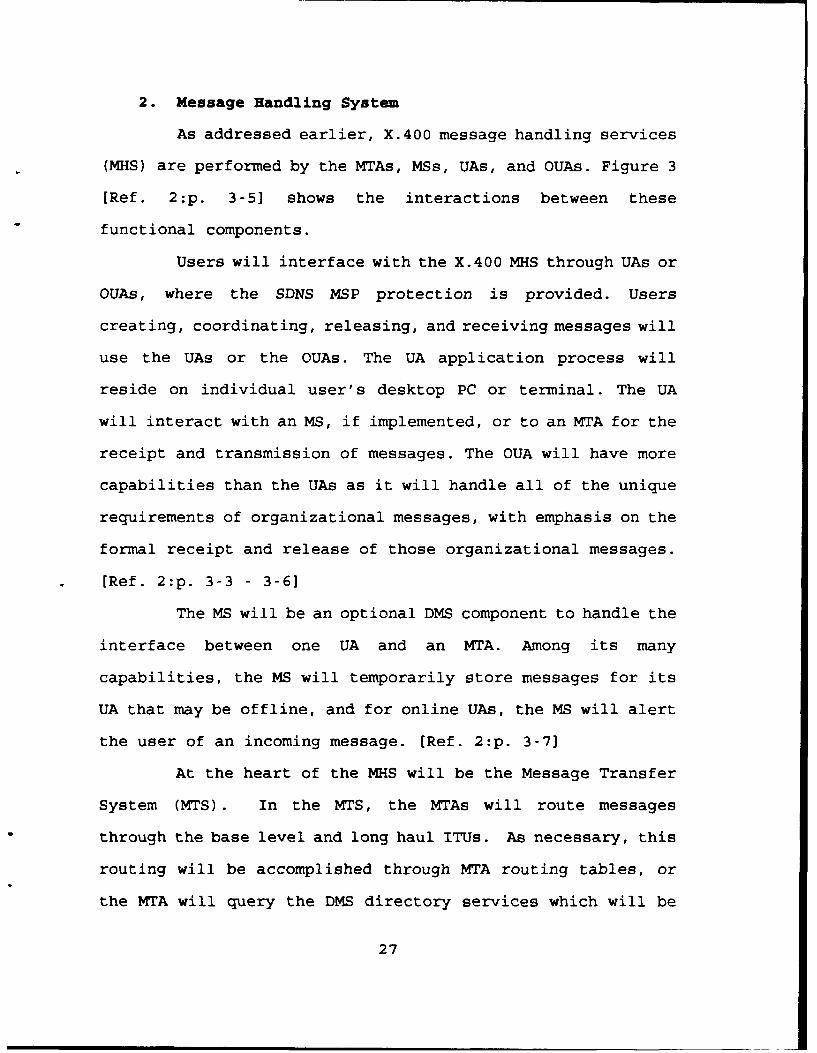
2. Message Handling System
As addressed earlier, X.400 message handling services
(MHS) are performed by the MTAs, MSs, UAs, and 0UAs. Figure 3
[Ref. 2:p. 3-5] shows the interactions between these
functional components.
Users will interface with the X.400 MHS through UAs or
0UAs, where the SDNS MSP protection is provided. Users
creating, coordinating, releasing, and receiving messages will
use the UAs or the 0UAs. The UA application process will
reside on individual user's desktop PC or terminal. The UA
will interact with an MS, if implemented, or to an MTA for the
receipt and transmission of messages. The OUA will have more
capabilities than the UAs as it will handle all of the unique
requirements of organizational messages, with emphasis on the
formal receipt and release of those organizational messages.
[Ref. 2:p. 3-3 - 3-6]
The MS will be an optional DMS component to handle the
interface between one UA and an MTA. Among its many
capabilities, the MS will temporarily store messages for its
UA that may be offline, and for online UAs, the MS will alert
the user of an incoming message. [Ref. 2:p. 3-7]
At the heart of the MHS will be the Message Transfer
System (MTS). In the MTS, the MTAs will route messages
through the base level and long haul ITUs. As necessary, this
routing will be accomplished through MTA routing tables, or
the MTA will query the DMS directory services which will be
27

C
o
M- Z
a 0
CE E
tm
b m i-.
4nn
Figure 3 DMS Message Handling System Functional Model
28

available at either the base or long haul levels. [Ref. 2:p.
3-7 - 3-8]
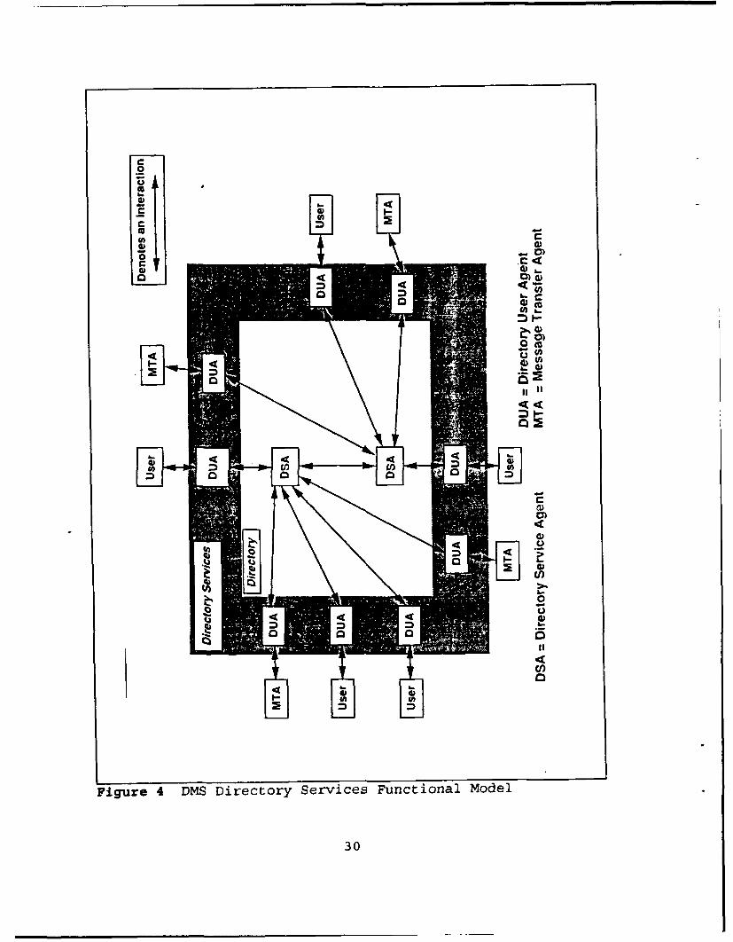
3. Directory Services
DMS directory services will be developed using the
X.500 standards. It will be the source for the directory name,
the O/R address, and other required information. Figure 4
[Ref. 2:p. 3-9] contains a functional model of the proposed
directory services.
Within the DMS, the hierarchical DIR will be distributedand will have the capability to translate between userfriendly names and machine oriented O/R addresses; assistin authenticating the identity of MHS functional agents(i.e., UAs, OUAs, MSs and MTAs); store information on usercapabilities and messaging services profiles; assist inthe expanding distribution lists supplied by the MHS intoindividual O/R addresses; and assist in updating therouting tables at each MTA. [Ref. 2:pp. 3-8 - 3-9]
Individual and organizational users will manually, and
MTAs will automatically, interface with the DMS Directory
Services through a Directory User Agent (DUA) that will
provide unique O/R addresses of intended message recipients.
The DUA will store a list of some of the most commonly used
names and O/R addresses used by the users and MTAs. This list
will help speed up the process by eliminating the need for the
DUA to interact with the DSA for every address. This list will
be interactively updated by the DSA and the DUA. At the heart
of Directory Services will be the "Directory" which is
composed of interconnecting Directory System Agents (DSAs)
that connect with the DUAs. Multiple DUAs will be served by
29
0
Cl
0
eU)M4
M
Figue 4 DMS iretor Serice Fuctioal ode
300
one DSA. The DSA will be the distributed, hierarchical
application process that will include and provide access to
the Directory Information Base (DIB). [Ref. 2:pp. 3-8 - 3-11]
4. MSP Gateway
A specialized gateway will be needed to interface the
DMS community using the SDNS MSP with non-DOD entities using
the X.400/X.500 protocols and not using SDNS MSP. If
necessary, the MSP Gateway will decrypt the incoming message,
encrypt it using SDNS MSP, and transmit to the intended
recipient. The reverse process will be used for outgoing
messages. [Ref. 2:p. 3-12] In Figure 2, the MSP Gateway is
shown as connected to the long haul ITU. Note that the other
networks and systems that may connect to this gateway will not
be considered part of the DMS architecture.
5. Management
Like the Directory, management functions also will be
hierarchical and distributed, meaning that they will not be
centrally located. These automated functions support the
overall DMS architecture and all of its users, and are shown
in Figure 4 as connected to the base level and long haul ITUs.
Management will include the enhanced performance of the
overall MHS through the monitoring of the network's status and
performance, and also through directory service maintenance
and network configuration control. [Ref. 2:p. 3-11]
31

6. Security
Security will consist of DMS security policies,
procedures and guidance developed as part of the phased
implementation, together with the supporting security
components. As noted in Figure 2, SDNS MSP security protocol
protection will be required at the UAs and OUAs to ensure that
writer-to-reader encryption is provided. Other security
services will likely include confidentiality, data integrity,
authentication, access control, and non-repudiation throughout
various portions or all of the network. [Ref. 2:pp. 3-11 -
3-121
A three-phased strategic approach has be identified in
order for the DMS baseline system of 1989 to smoothly evolve
into the target architecture of 2008. This DMS phased
implementation strategy is addressed below.
F. DMS PHASED IMPLEMENTATION STRATEGY
The implementation strategy consists of three phases
starting in 1989 with the identification of the DMS baseline
and a planned completion in the year 2008 with the system's
full operational capability. Figure 5 [Ref. 2:p. 4-21 shows
major planned actions during the three phases to the DMS
implementation strategy. These items are addressed below.
The "evolutionary transition" to the target architecture
is based on compliance with various DMS objectives. These
objectives include: reducing cost and/or staffing, satisfying
32

wwC,)
0.0~0
M
0
SU
0
C,),4qzz
* * 0
* FS
* . Z
6 01- U1
w t4S
0 0
00
C33
operational and service/agency requirements, extending the DMS
interface closer to the user, and providing enhanced
flexibility through the compliance with various standards,
such as the Government Open Systems Interconnection Profile
(GOSIP). [Ref. 2:pp. 4-11 - 4-13]
The implementation strategy calls for backward
compatibility. This concept will support the evolution to the
target architecture through multiple releases of various
software and hardware DMS components combined with new
policies and procedures. These releases will allow a phased
deployment of new DMS components while at the same time
aggressively phasing out "obsolete components, procedures,
protocols, formats, and media." [Ref. 2:p. 4-11 This means
that dual capabilities, both new and old, will be supported
until the old baseline and intermediate transitional
capabilities are phased out.
For the purpose of this thesis, Phases 1 will be described
in more detail than the subsequent two phases. This approach
is taken since Phase 1 is currently in progress (as of 1992),
and it presents issues that the Coast Guard needs to consider.
These issues will be addressed in Chapter IV. In addition, the
details of actions and projects planned for Phases 2 and 3
will be subject to changes due to the lessons that will be
learned during Phase 1, and also due to new technology that
will become available in the future.
34

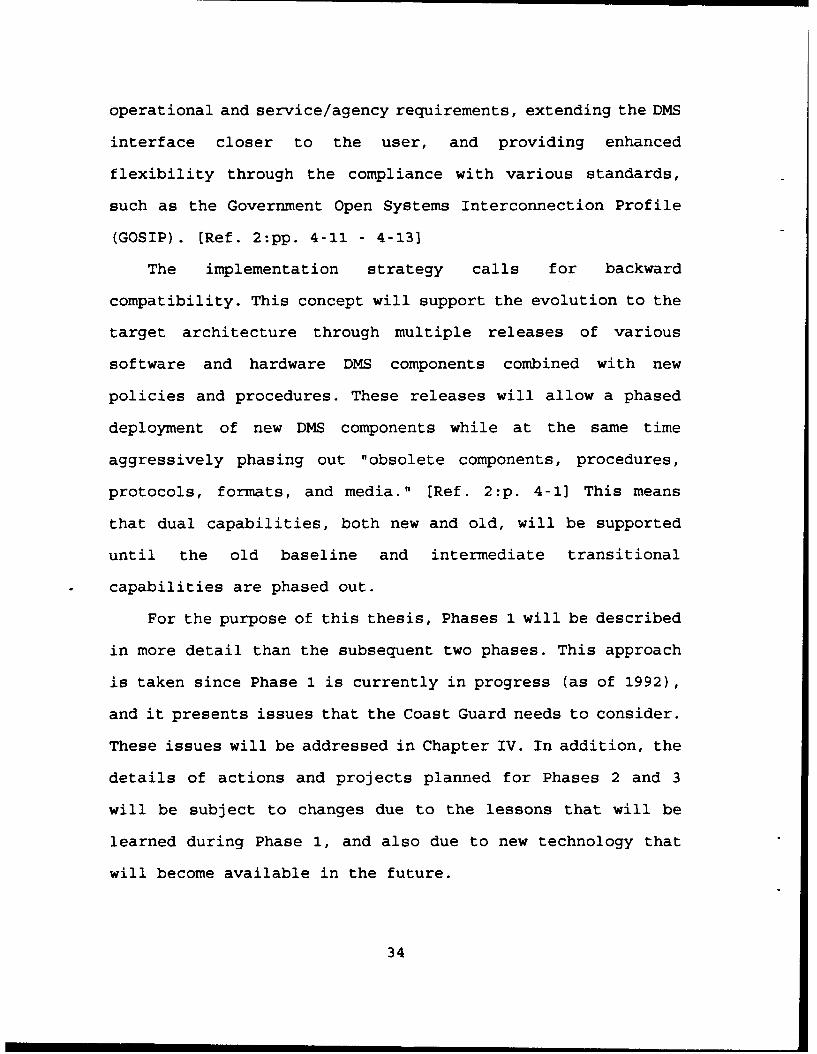
1. DMS Phase 1
Phase 1 is highlighted by the automation of the TCCs
for future phaseout, and the creation of regional and base
level interfaces between AUTODIN and DDN. The DMS Phase 1
architecture is shown in Figure 6 [Ref. 2:p. A-21. Actions
taken during Phase 1 will lead to the eventual phasing out of
baseline ASCs, AMPEs, and TCCs. [Ref. 2:pp. A-2, A-16]
a. TCC Automation
TCC automation will reduce TCC staffing and costs,
while at the same time bring the system's interface closer to
the users. This involves the automation of the electronic
transfer of messages to and from users verses the use of hard
copy printouts. Some of the Navy's TCC related projects
include the Remote Terminal System (RTS), the Personal
Computer Message Terminal (PCMT), the GateGuard, and the
Multi-level Mail Server (MMS). [Ref. 2:pp. 4-1 - 4-2, A-3 -
A-4]
b. AUTODIN-to-DDN Interface
Figure 6 shows both the regional and base level
AUTODIN-to-DDN Interfaces (ADIs), called R-ADI and B-ADI,
respectively. The R-ADI gateway will provide initial
connectivity and the selected transfer of narrative and data
pattern traffic between ASCs and the DDN. The B-ADI provides
a gateway interface between AMPEs and tie DDN. B-ADI
components shown in Figure 6 are the AUTODIN Mail Server (AMS)
35
4w
400
44K
Figue 6 MS Pase1 Arhitetur
360

software application for message format conversions and the
BLACKER Front End security device at a standard E-Mail host
that will contain a variety of communications protocols.
[Ref. 2:pp. A-Il - A-14]
c. Directory Improvements (MCS and X.500 DIB)
These directory improvements will include the
Message Conversion System (MCS), which will be connected to an
ASC, and X.500 Directory Information Base (X.500 DIB), which
will be connected to the DDN. These mutually supporting
improvements will facilitate message preparation, reduce the
manual PLA-to-RI operations and AMPE/TCC database maintenance
efforts, and support ADI capabilities. [Ref. 2:p. A-8]
d. X.400 E-Mail
Early DMS subscribers will have their user
terminals and E-Mail hosts transition to an X.400 E-Mail
service using MTAs and UAs (same hardware). These systems will
need to be upgraded to meet DMS requirements (i.e.,
organizational message related issues) such as reliability,
availability and responsiveness of hosts, and security
protection, authentication and access control for message
integrity and security. [Ref. 2:pp. A-14 - A-15]
X.400 messaging will require new message formats
and procedures. There are plans for a new Allied
Communications Publication (ACP) that will address the new
Common Message Format (CMF). This ACP will serve as an
37

international standard for the use of X.400 and X.500
protocols. These protocols will be the basis for the phase out
of AUTODIN and non-standard E-mail formats and procedures.
[Ref. 2:p. A-16]
e. Open System Interconnection Gateway
During Phase 1, this OSI application level gateway
will provide limited unclassified individual user message
translation capabilities between the SMTP and X.400 protocols.
This initial capability will start the process of
transitioning existing systems or installing X.400 based MTAs
and UAs. [Ref. 2:p. A-8]
2. DMS Phase 2
Phase 2 is scheduled to start in 1995 when the initial
operational capability is available for X.400/X.500 individual
and organizational messaging with SDNS MSP protection. Phase
2 is planned to be completed when the last ASC is phased out
in approximately the year 2000. As noted in Figure 5, many of
the projects started in Phase 1 will be completed, with
organizational messaging transition and TCC phaseout
continuing into Phase 3. This complex transition to
organizational messaging spans all three DMS phases. Phase 2
will be characterized by significant hardware and personnel
changes from what was known in the DMS baseline. [Ref. 2 :p.
B-1]
38
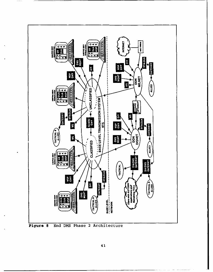
Figures 7 and 8 [Ref. 2:pp. B-5 - B-6] show the early
and ending Phase 2 architectures, respectively. Figures 7 and
8 differ from the DMS Phase 1 Architecture (Figure 6) in that,
in general, more detail is shown. First, the Phase 2
architectures are shown with "Base Level" and "Network"
sections. This is easily seen by the separating dashed line in
the middle of Figures 7 and 8. These sections represent the
separation between the future base level and long haul ITUs.
Another different separation is now shown between the
unclassified and classified portions to the IITS and the DDN.
In Figure 6, the DDN was shown as a "cloud." In Figures 7 and
8, the DDN is shown in more detail with guard gateway
separating the DISNET and the MILNET, with a mail bridge to
the Internet. Figures 7 and 8 show the base level transmission
system and the existing user interfaces (the workstations);
they were not included in Figure 6.
In Figure 7, the AUTODIN part of the architecture is
shown in less detail (as compared to Figure 6). In Figure 8,
the remaining AUTODIN users and TCC are drawn as a "cloud"
with a DIN/DMS gateway to connect the cloud to the DDN DISNET
and MILNET networks.
Two important aspects to Phase 2 will be the initial
capability to handle classified messages with X.400 MHS and
X.500 directory services over the SDNS, and the complete
phaseout of two primary AUTODIN components, the AMPEs and
ASCs. When Phase 2 is completed, there will no longer be an
39

0 - 994
UiE
40)
z
ii ru4z
0-0
IiiT
ziFigue 8 nd MS Pase Arhitetur
41

AUTODIN. While AUTODIN components are being phased out, the
transitional components fielded in Phase 1 will :_.her be
integrated and upgraded, or phased out altogether. Thi-s
process will continue until the DMS full operational
capability is provided. [Ref. 2:pp. 4-3]
As the middle phase to the overall transition
strategy, Phase 2 bridges the initial action taken during
Phase 1, and positions the DMS for transitioning into Phase 3.
Phase 2 objectives are summarized as follows:
"* Expand writer-to-reader connectivity and support. Thisis done with new or upgraded user PCs or desktopterminals (UAs, 0UAs, MSs, and MTAs with X.400 MHScapabilities) and related X.500 directory services withDUAs, DSAs, and DIBs).
"* Provide writer-to-reader message security services.This security service is provided through pre-MSP andMSP (application layer security), and lower layersecurity at the interfaces to the base level and longhaul transmission networks.
"• Phase out baseline messaging systems. This includes theTCCs, the AMPEs, the ASCs, and the SMTP.
"* Phase out baseline messaging formats and procedures. Anew ACP prescribed CMF will replace AUTODIN's ACP-127and JANAP-128, and DDN's E-Mail format.
"* Maintain message exchange interoperability between theDMS and non-DMS systems. This is provided throughDIN/DMS gateways which will replace the ADIs,
"* Implement Phase 2 in a cost effective manner. This isaccomplished sharing DMS applications among users, byusing existing hardware/capital investments wherepossible, and planning for scheduled upgrades to becompatible with DMS objects. [Ref. 2:pp. 4-3, B-i - B-3]
42
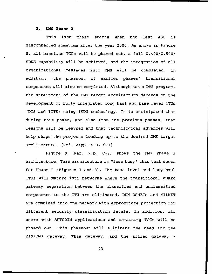
3. DMS Phase 3
This last phase starts when the last ASC is
disconnected sometime after the year 2000. As shown in Figure
5, all baseline TCCs will be phased out, a full X.400/X.500/
SDNS capability will be achieved, and the integration of all
organizational messages into DMS will be completed. In
addition, the phaseout of earlier phases, transitional
components will also be completed. Although not a DMS program,
the attainment of the DMS target architecture depends on the
development of fully integrated long haul and base level ITUs
(DIS and IITS) using ISDN technology. It is anticipated that
during this phase, and also from the previous phases, that
lessons will be learned and that technological advances will
help shape the projects leading up to the desired DMS target
architecture. [Ref. 2:pp. 4-3, C-1]
Figure 9 [Ref. 2:p. C-31 shows the DMS Phase 3
architecture. This architecture is "less busy" than that shown
f or Phase 2 (Figures 7 and 8) . The base level and long haul
ITUs will mature into networks where the transitional guard
gateway separation between the classified and unclassified
components to the ITU are eliminated. DDN DSNETs and MILNET
are combined into one network with appropriate protection for
different security classification levels. In addition, all
users with AUTODIN applications and remaining TCCs will be
phased out. This phaseout will eliminate the need for the
DIN/DMS gateway. This gateway, and the allied gateway -
43

0Lai-$.-
w a-
U) z
ii 1 0Iim
LU--c 7,
4 a
ma z
Figure 9 DMS Phase 3 Architecture
44

MTA/DUA connections to the base level and long haul ITUs (from
Phase 2), will continue to provide interoperability to non-DMS
users. In general, users will interface with the base level
ITU through workstations that handle either classified or
unclassified information.
G. SUMMARY
This chapter provides the reader with current DMS
information. The DMS started with a baseline in 1989 and will
end with a target architecture around the year 2008. This
twenty year transition will be accomplished through a phased
implementation strategy that will install transitional
components to meet the needs of both the old and new systems
and networks, and will eventually phaseout or upgrade the DMS
baseline systems and networks that were used in 1989. It is
the author's opinion that it is important that all military
services, including the Coast Guard, and DOD/government
agencies using the DMS baseline systems and networks be
involved with the DMS Program so that their messaging needs
are addressed, and so that they will be prepared to meet the
challenges that DMS will undoubtedly present to them.
The following chapter will address the basic Coast Guard
messaging systems and networks used in 1992. This information
corresponds to the DMS baseline and Phase 1 type of
information.
45
III. U.S. COAST GUARD TELECOMMUNICATIONS SYSTEM
A. INTRODUCTION
This chapter briefly addresses the Coast Guard's
telecommunications organization and identifies elements of the
Coast Guard Telecommunications System (CGTS). Also addressed
is the Coast Guard Standard Workstation (CGSW) and various
telecommunications/message related software application
programs that run on the CGSW. Following the description of
the CGSW are descriptions of the various message related
networks and systems used by the Coast Guard and the future
plans for the CGTS.
B. COAST GUARD TELECOMMUNICATIONS ORGANIZATION
Like the other military services, the Coast Guard has a
hierarchical telecommunications organization that spans the
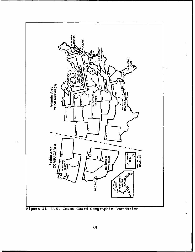
Coast Guard organization. Figure 10 [Ref. 9:p. 1.1.2] is a
simplified diagram of the overall Coast Guard organization.
This organization reflects the assignment of military command,
and operational and administrative responsibilities and
authorities among components in Coast Guard Headquarters,
Areas, Districts, Maintenance and Logistics Commands (MLCs),
and field units. Figure 11 [Ref. 9:p. 1.1.3] shows the various
geographic areas of responsibility for the area and district
commands. In general, the chain of command is from the
46

U- V)
Ix o I-- -
:: Z ,I-. C;).,
0- "hI 0 0-w -1ý- U)0
z 0.< z
z :1
oGo
()C.
0 0q
0 Li
V))
0 V,
W2
•l 0.. 1 /
I-
::I<
I-0
Figure 10 U.S. Coast Guard Organization
47
0-z
U
UJ
33
II
48
00
Figure% 11 U.S CosSur Gorpi Budre
48a

Commandant to the area commanders, and from the area
commanders to the district and Maintenance and Logistics
Command (MLC) commanders, or area units, and then, in turn, to
the subordinate operating or logistics units. [Ref. 9:pp.
1.1.9] The following descriptions are of Coast Guard
telecommunications elements at the various command/unit
levels. Over the years, the Coast Guard's telecommunications
organization has changed in both how the structure looks and
works, and also in the names used. As time passes, it would
not be particularly unusual for this organization to undergo
further changes. One example is the possibility of changing
the District (dt) Chief of Staff element to a division statug.
1. Coinandant/Neadquarters Level
At the top is the Coast Guard's military service
Headquarters located in Washington, DC. One of the ten offices
at Coast Guard Headquarters is the Office of Command, Control
and Communications (G-T) or Commandant (G-T). The "G" in G-T
was assigned by the Department of Transportation (DOT) to keep
Coast Guard Headquarters separate from other DOT Washington-
area agencies and organizations. The "T" in G-T was a holdover
from when the office was called Telecommunications. G-T is
"responsible for developing policy for, maintaining managerial
oversight of, and acquiring communications, information
systems, and electronics equipment support for an effective
49

command and control network to fulfill Coast Guard management
and operational requirements." [Ref 10:p. 3-1]
2. Area CozJzand Level
The Coast Guard Atlantic and Pacific Area Commands are
located on Governors Island, New York, NY, and Coast Guard
Island, Alameda, CA, respectively. Area telecommunications
responsibilities are managed by the Information System
Division (At/Pt) and the Telecommunications Branch (Att/Ptt).
The "A" in At/Att and "P" in Pt/Ptt respectively stand for the
Atlantic and Pacific geographic areas of responsibility. These
divisions and branches are responsible for planning,
evaluating, coordinating, and supervising all changes and
upgrades to the overall inter-district system control aspects
of telecommunications and information systems within their
respective geographic areas of responsibility. This also
includes the operation of the area's Telecommunications Center
(COMMCEN), and control over the Coast Guard Communications
Area Master Stations (CAMS Atlantic and Pacific,
respectively), and the Coast Guard Communication Stations
(COMMSTAs) within the area command's region. The At and Pt
divisions are also respectively assigned as U.S. Naval
Atlantic and Pacific Maritime Defense Zones' command N-6 staff
element, respectively. [Ref. 9:pp. 3.3.26-3.3.30, Ref. 10:pp.
3-1, 7-4]
50

3. District Command Level
The Coast Guard has ten district commands located in
Boston, MA (First Coast Guard District or Coast Guard District
One (CGD1 or D1)); St. Louis (D2), MO; Portsmouth, VA (D5);
Miami, FL (D7); New Orleans, LA (D8); Cleveland, OH (D9); Long
Beach, CA (DI1), Seattle, WA (D13); Honolulu, HI (D14); and
Juneau, AK (D17) (see Figure 11). The numbering scheme for
these districts corresponds to older and no longer used U.S.
Naval Districts.
District telecommunications responsibilities are
typically managed by the Information Resources Management
Staff (dt) and the Telecommunications Branch (dtm or dttm).
This staff and branch are "responsible for the proper
planning, organization, operation, inspection, supervision,
and coordination of telecommunications for all activities
under the control of the district." This includes the
operation of the district's COMMCEN. [Ref. 9:p. 4.1.16, Ref.
10:pp. 3-1 - 3-2)
4. Maintenance and Logistics Command Level
The Coast Guard has two MLCs, MLC Atlantic and MLC
Pacific, both of which are located at the same geographic
locations as the area commands, in New York, NY, and Alameda,
CA. In general, the MLCs provide various support services
directly to individual units. Telecommunications related
support is provided by the Command, Control, and Communica-
51

tions (C3) Technical Support Division (t) and its Tele-
communication Systems Branch (tts). [Ref. 9:pp. 5.1.4, 5.1.461
5. Headquarters Units
There are various Coast Guard commands that provides
service-wide support or support to satisfy a requirement in a
specific geographic area. These commands operate under the
Commandant, who is assisted by a Headquarters Office Chief who
exercises technical control over those Headquarters units.
Commandant (G-T) exercises technical control over the
following Coast Guard Headquarters units that provide
telecommunicationo-related support: [Ref. 9:pp. 6.1.3 - 6.1.5,
6.1.29, 6.1.31]
"* Information Systems Center (ISC), Alexandria, VA
"* Electronics Engineering Center (EECEN), Wildwood, NJ
"* Operation Systems Center (OSC), Martinsburg, WV
6. Field Units
a. Communications Stations
Under the direction of the area commander,
communications stations (COMMSTAs) provide command and
control, and other support communications services to afloat
units. [Ref. 10:p. 7-4] Message support is primarily intended
for vessels located within the COMMSTA's geographic area of
responsibility. These commands are the interface between the
shoreside and afloat messaging networks and systems.
52

b. Group Offices
Groups, which are district-level commands, are
included because they operate and maintain the Group
Telecommunications Systems (GRU COMMSYS), which include
messaging systems. The geographic area of responsibility for
each district command is subdivided into contiguous groups.
The number of groups within each district varies depending on
many factors, including the geographic size and missions
performed. Each group typically has a COMMCEN that serves as
a focal point for all communications activities within the
group, including messaging services. Group personnel typically
perform search and rescue and law enforcement operations with
patrol boats (PBs) and small boats. [Ref. 10:p. 7-7]
C. COAST GUARD TELECOMMUNICATIONS SYSTEM
The CGTS provides "the connectivity to meet all Coast
Guard information system telecommunications," with a goal of
supporting all Coast Guard missions [Ref. 12:p. 1]. It is a
combination of the needs of all of these missions that drives
the CGTS. The CGTS includes "the people, facilities, and
systems (hardware and software) orchestrated to meet the
telecommunications needs of the Coast Guard." A goal for the
CGTS is to be "a responsive, robust, and cost effective
information transfer system." The CGTS has four principal
components: voice, record message, data, and image
transmissions. [Ref. 12:p. 1] This thesis is primarily focused
53

on message-related issues, therefore, voice, data and image
transmission issues will not be directly addressed. The phrase
"record messages" directly relates to DMS organizational
messages. Additionally, in the Coast Guard, E-Mail is
considered not only to be what DMS refers to as an individual
message, it also includes the system used to send both formal
and informal messages. [Ref. 13:pp. 1-2] A formal Coast Guard
message directly relates to the DMS organizational message,
and an informal Coast Guard message directly relates to the
DMS individual message.
1. Definition of the CGTS
The CGTS refers to the radio, telephone, and landline
facilities owned, controlled, or used by the Coast Guard, and
also includes associated terminal facilities, techniques and
procedures. The following are the three major CGTS subsystems:
* Area Telecommunications Systems (AREA COMMSYS) whichinclude the CAMS, the COMMSTAs, COMMCENs, andTransportable Communications Centrals (TCCs).
* District Telecommunications Systems (DIST COMMSYS).
* Group Telecommunications Systems (GRU COMMSYS). [Ref.10:p. 1-1]
2. CGTS Mission
The mission of the CGTS is to:
* Provide and maintain reliable, secure and rapidtelecommunications to meet the needs of Command,Control and Communications (C3) of operational CoastGuard forces.
54

* Ensure connectivity, compatibility and interoperabil-ity with the National Command Authorities (NCA) andFederal Executive Agencies, especially the Navy.
* Provide effective interface with the marinetransportation industry and the boating public insupport of global distress and safety systems whichprovide rapid and appropriate aid to vessels, personsand aircraft in distress.
* Provide telecommunications services, includingfrequency management, record message service,telephone and data service for administrative supportof Coast Guard facilities. [Ref. 10:p. 1-1]
Coast Guard telecommunications is conducted according
to various Coast Guard directives and standard operating
procedures issued by the Commandant, area and district
commanders, and at the command/unit level. Coast Guard
telecommunications is also guided by International Radio
Regulations, joint and allied/combined communications
instructions (e.g., JANAPs and ACPs), and Naval
Telecommunications Procedures (NTPs). [Ref. 10:p. 1-3]
D. COAST GUARD STANDARD WORKSTATION
In 1981, the Coast Guard contracted with the C3
Corporation for the first Coast Guard Standard Workstation
(CGSW). The workstation was originally called the C3, now it
is called the CGSW I. The CGSW I was an early, Intel 8086-
logic-based, Convergent Technologies Corporation Computer.
This standard, service-wide computer was used primarily for
office automation in standalone and local area network (LAN)
configurations which used the proprietary operating system
55

called Convergent Technologies Operating System (CTOS). The
CGSW I provided advantages of compatibility and connectivity.
This low speed PC was able to meet the then growing needs of
the Coast Guard due to design capabilities/options such as:
modems, storage, printing, programming, and upgrade options.
In 1987, C3 Corporation introduced, and the Coast Guard
purchased, C3's modular computers which were called "N-GEN"
for new generation. By default, the older equipment became
known as "O-GEN" for old generation. This new equipment had
Intel 80186, 80286, or 80386 processors. The 80386 processor
was very expensive and was not widely used due to the limited
requirements of the time and the initial purchase costs. [Ref.
14:pp. 51-53, Ref. 15:pp. 5-71
In 1988, the Coast Guard contracted with the Unisys
Corporation for the next generation CGSW, called the CGSW II.
Prior to this, Unisys had purchased the Convergent
Technologies Corporation, which included CTOS. Unisys was able
to deliver the same hardware and software that were in the
CGSW I. Also during this contract an agreement was reached for
the delivery of Unisys's Burroughs Operating System (BTOS).
Developments by the end of 1991 resulted in the merger between
CTOS and BTOS with the newer CTOS II version 3.3. The 1988
contract with Unisys is scheduled to end in 1992. The next
CGSW contract will require new equipment to be compatible with
older systems and also provide new capabilities based on the
support of all Coast Guard communications needs. Several
56

communications related software application programs used on
the CGSW are addressed in the following subsections. [Ref.
14:pp. 51-53, Ref. 16:p. 3]
1. Automated Message Preparation
The Automated Message Preparation (AMP) subsystem is
used by personnel authorized to draft, review, and transmit
record messages. It provides support to the user for basic
message formatting. With the AMP, the user can transmit
messages to the Coast Guard Data Network using the Information
Transfer Distribution System. [Ref. 14:p. 5-23]
2. Information Transfer Distribution System
The Information Transfer Distribution System (ITDS)
was formerly called the Message Transfer Distribution System
(MTDS). The name change reflects the capability to
automatically transfer both messages and data using electronic
mail capabilities. For messages, the ITDS takes a message from
the outgoing message queue, "wraps" it in an E-Mail envelope
(as an attachment to the E-Mail), and sends it to other ITDS
E-Mail locations. On the receiving end, the ITDS "unwraps" the
E-Mail envelope, and puts the message in the incoming queue.
Refer to Figure 12 [Ref. 17:p. 10] for a diagram of this
process. The ITDS is configured as an external CGSW circuit
and uses an end-to-end encrypted X.25 network for
transmission. External circuits, like AUTODIN, are circuits
where incoming messages can not be immediately resent to by
57

GOut
Encryption "i
~In
Reject QueueManager
Figure 12 E-Mail Envelope Concept
the ITDS software. This prevents duplicate messages from being
resent back onto the external circuits. The encryption device
between the CGSW and the X.25 network is the Cipher X5000
Datacryptor. The Cipher X5000 meets the National Institute of
Standards and Technology (NIST) Data Encryption Standard
(DES) . The Cipher X5000 has also been endorsed by the National
Security Agency (NSA) as having met the requirements of
various federal standards. [Ref. 14:p. 5-25, Ref. 17 :p. 10,13]
58

3. X.25 District Network
The X.25 District Network (X25D) is the same as the
ITDS, except it uses internal CGSW circuits. The X25D is the
designator for the District Level Network which uses the Coast
Guard Data Network. Internal circuits are circuits where
incoming messages may be resent to by the X25D software.
Duplicate message routing may be necessary to ensure delivery
to all intended "internal" recipients. The X25D is replacing
an older network procedure that used a polling protocol. [Ref.
17 :pp. 4, 10]
4. BTOS OFIS Mail
BTOS OFIS Mail (B-Mail) is Unisys's electronic mail
system that is used on CGSWs. B-Mail allows messages and
separate attachments to be sent transparently from one
user/location to another. B-Mail attachments can be either
official or unofficial in nature. Examples of official B-Mail
attachments can include Coast Guard directives (instructions
and notices), correspondence (letters and memorandums), and
record messages. Asychronous B-Mail access is provided by the
Terminal Mail Manager. [Ref. 14 :p. 5-10]
5. X.25 Applications
Unisys's X.25 Communications Manager and the X.25
Network Gateway programs allow Unisys E-mail to be sent
between Coast Guard E-mail centers over an X.25 Public Packet
Switched Network (PPSN), such as Sprintnet, and also over the
59

DDN. The X.25 Communication manager's features include X.25
communications, full duplex operation, multiple connections,
simple operation, and authentication. The X.25 Network Gateway
application program conforms to CCITT X.25 requirements and
also provides the following features: X.21 Circuit Switched
Service (CSS) Support, Event Management System (EMS) Support,
Multiple Gateway Server (MGS) Support, DDN Support, and X.25
Agent. The CCITT X.25 requirements define the interface
between PPSNs and user devices, called Data Terminal Equipment
(DTE), operating in a packet switched mode. This gateway
program addresses the Open Systems Interconnection (OSI) lower
three layers, which are called the physical, data link, and
network layers. [Ref. 18, Ref. 19]
6. Standard Semi-Automated Message Processing System
The Standard Semi-Automated Message Processing System
(SSAMPS) is the Coast Guard's record message routing system
that directs the flow of record messages based on plain
language addressees (PLAs). Messages are received,
transmitted, and routed between external circuits (the ITDS
and the AUTODIN) and internal circuits (X25D). All Coast Guard
record message circuits or networks terminate at a SSAMPS.
These different circuits can have different communications
protocols. Refer to Figure 13 [Ref. 14:p. 5-52] for a diagram
of the processes involved the with CGSW SSAMPS. Incoming
messages received from a circuit are automatically put into an
60

(AI
0
61
incoming queue based on the precedence of the message. The
router background application program routes the message to
appropriate outgoing message queues for automatic transmission
to the appropriate desired circuit, and also automatically
sends an electronic copy to an archive data base for storage.
The Log Server (LOG or LOGSERV) is the log keeping background
software program that receives and can provide information on
system and message statuses. The Interactive Message Manager
(IMM) is a foreground menu-driven software program that the
user/operator uses to monitor and control the message
processing software. [Ref. 17:pp. 3-5, Ref. 14:pp. 5-52 -
5-54]
7. SORTS Message Writing Utility
This utility program assists users in creating SORTS
readiness related messages by duplicating the SORTS worksheet
for data input, and then properly formatting the data for
message transmission [Ref. 14:p. 5-34]. This is one example of
how an automation program can assist users in creating
specifically formatted messages.
8. Network Security Software
The Network Security Software (NSS) allows the system
manager/user to specifically select which volumes and
directories remote users may access at Coast Guard nodes. By
default, the entire system is protected. [Ref. 14:p. 5-30]
62
E. NETWORKS AND SYSTEMS
Coast Guard policy calls for long haul data and record
traffic transmissions to be accomplished on record or data
networks such as a Public Data Network (PDN), such as
Sprintnet (formerly called Telenet); the AUTODIN and the DDN
(addressed in Chapter II); and the Coast Guard's Secure Data
Network (SDN) (formerly called the Secure Command and Control
Network (SCCN)). Short haul connections are accomplished in a
variety of forms which include the use of modems over
telephone lines, Coast Guard microwave, and dedicated
cables/lines. [Ref. 10:p. 9-2; Ref. 20:p. iv]
1. Coast Guard Data Network
The Coast Guard Data Network (CGDN), previously called
the Hybrid Data Network (HDN), is a reliable, high speed, and
relatively inexpensive data and record message network used to
elpztronically connect Coast Guard commands and units. In
1991/1992 the network was both public and private. It was
putlic from the perspective that the Coast Guard uses a PPSN,
ca'led Sprintnet, and is private in that it uses Coast Guard-
owned/operated hardware (computers, switches, and cables).
[R.-f. 20]
In 1991/199Z the CGDN is in a significant change
status and is being reconfigured in order to convert the
network to an all-private network through FTS 2000 data
connections between Coast Guard-owned switches (TP4) and
63
concentrators (TP3). Figure 14 [Ref. 21] shows the future CGDN
private network backbone. TP4 Packet Switching Nodes (PSNs)
are located at Coast Guard Headquarters, at area/MLC (LANT and
PAC) and district commands, and the Coast Guard Operations
Systems Center. The 1991/1992 situation shows that these PSNs
use Sprintnet for connectivity. Tn the future, these PSNs will
be interconnected by dedicated lines capable of handling
56,000 bits per second (56K BPS) of information (64K BPS if
control information is included). The CGDN uses the CCITT X.25
standard for packetized data transmissions. In addition to the
TP4 data switches and TP3 concentrators, the CGDN also uses
microwave and modem equipment. This and other communication
equipment make the CGDN a hybrid data network
The CGDN uses the E-mail architecture, that is, a
hierarchical network of CGSW mail centers, with a post office
mail center serving as the router for subordinate mail centers
or nodes (if any) on a multiple CGSW cluster or LAN. This
hierarchical network of mail centers calls for a standard
Coast Guard-wide naming convention and directory, that will
support OSI standards and compatibility with the Internet.
These procedures are contained in COMDTINST 5270.1 [Ref. 13].
[Ref. 20:p. 4-1, Ref. 22:p. 10]
2. Automatic Digital Network
As addressed in Chapter II, the AUTODIN is a non-Coast
Guard network. It is a DOD store-and-forward message switched
64

(3r
>11-7O
Figure 14 Coast Guard Data Network's Future Backbone
65

network that is managed and controlled by the Defense
Information Systems Agency (DISA). This network is primarily
used by the Coast Guard for long-haul classified message
transmissions, and it also provides interoperability between
the Coast Guard and DOD, including the U.S. Navy and others.
The U.S. Navy sponsors and pays for the Coast Guard's access
to the AUTODIN, and therefore the Coast Guard is a non-
claimant user of the network. [Ref. 221
Appendix A [Ref. 22] identifies the Coast Guard
locations that have access to AUTODIN, and the AUTODIN
connection locations, such as an AUTODIN Switching Center
(ASC), an Automated Message Processing Exchange (AMPE), or a
Telecommunication Center (TCC). All of these Coast Guard
locations either presently have or are in the process of
reconfiguring to Zenith/INTEQ Inc's Message Distribution
Terminal to connect with the AUTODIN. The following subsection
describes this terminal.
a. Message Distribution Terminal
In February 1991, the Coast Guard formally decided
to begin the transition from the then-labor-intensive,
torn-paper-tape type AUTODIN-related hardware to the automated
Message Distribution Terminal (MDT). Prior to 1991, the Coast
Guard had fielded MDTs at the Pacific Area's COMMCEN to meet
the messaging needs of Commander in Chief, U.S. Pacific
Command's (USCINCPAC's) Joint Task Force 5 (JTF 5) and
66
Commander in Chief, Pacific Fleet's (CINCPACFLT's) Maritime
Defense Zone Pacific (MDZPAC). [Ref. 24] JTF 5 is a tenant DOD
command at Coast Guard Island, Alameda, CA, and MDZPAC is a
combined command with Coast Guard Pacific Area.
Figure 15 [Ref. 25] shows a simplified April 1992
configuration of messaging networks and systems at the Pacific
Area's COMMCEN. They used a three MDT configuration. This
configuration is different from other locations, such as the
D13 COMMCEN, because of the additional routing requirements
for JTF 5. One MDT is used for routing incoming and outgoing
messages to AMME Oakland. Incoming and outgoing messages for
JTF 5 and Coast Guard Pacific Area/MDZPAC are routed to
Pacific Area's MDT. The Pacific Area's MDT then routes as
follows: (1) it routes JTF 5 messages to their MDT for further
JTF 5 routing, (2) it routes classified Pacific Area/MDZPAC
messages to the Coast Guard's SDN/STU-III for further
classified routing, and (3) it routes Pacific Area/MDZPAC
unclassified/encrypted for transmission only/fow official use
only (UNCLAS/EFTO/FOUO) messages to a CGSW with the Coast
Guard's SSAMPS for further unclassified message routing. [Ref.
25]
The MDT is a PC-AT hardware and software based
system that is relatively inexpensive, user friendly, and
upgradable to new computer technology. It consists of a
workstation and monitor that is available in either the
TEMPEST or non-TEMPEST configurations. Refer to Figure 16
67
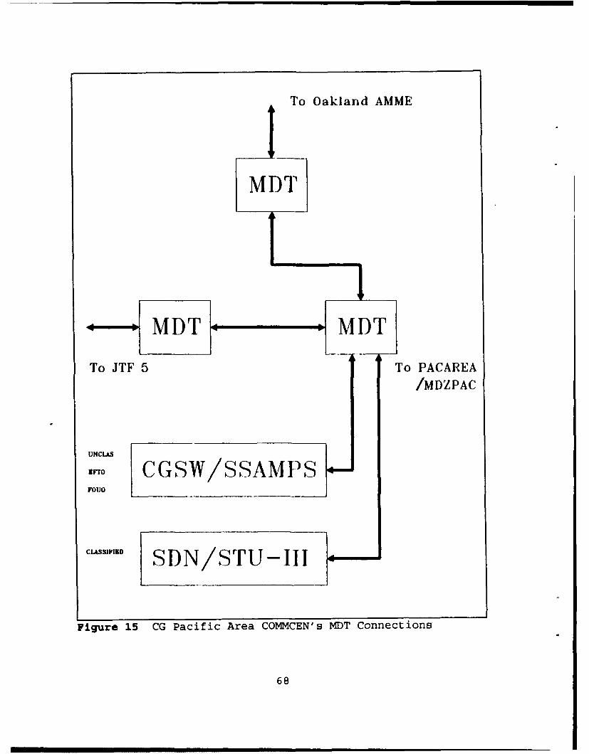
To Oakland AMME
MDT
To JTF 5 To PACAREA
/MDZPAC
UNCLAS
a.o CGSW/SSAMPSFOUO
CLa"SIVID SDN/STU- III
Figure 15 CG Pacific Area COMMCEN's MDT Connections
68

--- I
!:.ca---
Figure 16 Message Distribution Terminal (MDT)
69

[Ref. 26:p. 2] for Zenith/INTEQ's MDT diagram. The MDT's
software is written in the DOD's mandated Ada programming
language, and this software, combined with the hardware
workstation (together called the communication platform),
provides the following capabilities:
"* Implements JANAP 128 AUTODIN message format.
"* Provides AUTODIN message preparation and transmissionwith the capability to use other message system andprotocol.
"* Allows system security administrator to manage andcontrol all systems accesses, and allows or prohibitsany function to any user.
"* Provides capability to mix and match message protocolsand message formats.
"* Allows users to specify system-wide values, devicesecurity levels, automatic backup criteria, securitylevels for equipment, and alternate devises. [Ref. 26]
3. Defense Data Network
Refer to Chapter II for details on the Defence Data
Network (DDN). Like the command and control connections to
AUTODIN, the Coast Guard has similar connections to the DDN.
Appendix B [Ref. 27] identifies the Coast Guard's DSNET 1
connections which the Coast Guard pays for. These connection
are accomplished through the use of a modem or a direct
connection. In 1992 these connections are not generally used
for message transport purposes, however, DDN is used for data
purposes such as connectivity to the Joint Chiefs of Staff-
sponsored, multi-agency Anti-Drug Network (ADNET). ADNET is a
70

command, control, communications, and intelligence (C31)
network created to pass real-time counternarcoti-s information
between the DOD and various Law Enforcement Agencies (LEAs),
which includes the Coast Guard. DDN connectivity is also used
for interface to a number of other intelligence systems, such
as the Joint Maritime Intelligence Element (JMIE), Zincdust,
and Emerald. [Ref. 27]
4. Secure Data Network
The Coast Guard's Secure Data Network (SDN) provides
a capability for secure data and record message communications
up to the Top Secret level using a CGSW-based system. The SDN
is a computer terminal connected to a special STU-III secure
telephone. The SDN provides small units, both afloat and
ashore, with automated classified messaging capabilities and
connections to larger shore units, such as COMMSTAs, and
group, district, and area commands. These small units
typically have relatively low volumes of classified messages,
where the sending and receiving of messages requires a
messenger to deliver and/or pick up messages from a distant
messaging center. [Ref. 16:p. 2] Connections to SDN hardware
is accomplished in four ways: (1) through the use of a secure
dedicated line, (2) through STU-III dial-in/dial-out, (3)
through the use of floppy diskettes, and (4) to an output
paper printer. [Ref. 25] In addition to these connections,
messages can be created at the SDN/CGSW keyboard.
71
5. Federal Telephone System 2000
The Federal Telephone System 2000 (FTS 2000) is a U.S.
Sprint and AT&T operated, and General Services Agency (GSA)
managed, centralized network that will provide both telephone
and data communications. The U.S. Coast Guard falls under the
AT&T portion of the FTS 2000. FTS 2000 services include
circuit-switched voice or data, dedicated data, packet-
switched data, video, and switched digital integrated
services. ISDN capabilities are projected to be available
during or after 1992. [Ref. 14:p. 5-44]
F. FUTURE PLANS
In March 1991, the Coast Guard held a telecommunicaLions
conference in Virginia Beach, VA (commonly referred to as
VBII), "to assess the current technical and management status
of the Office of G-T and to set the direction for the 1990's."
The conference used Total Quality Management (TQM) concepts
'to create a vision, understand the current business
processes, to develop new designs for business processes, and
to evaluate the implementation of the new designs." [Ref. 28]
1. Vision Statement
The Coast Guard's messaging-related plans are related
to three of the five components of G-T's vision statement for
the year 2000 (developed at VBII) These components a&dressed
universal access and satisfying customer, user, and
72

organizational needs. These three components of this vision
statement are:
0 Every Coast Guard unit has universal access to alltelecommunications and information services regardlessof geographic location, unit size, platform, type oftransmission (e.g., data, voice, video, text), andsecurity requirements.
* G-T anticipates and satisfies emerging customer needsby providing users with information required to solvebusiness problems.
* The Coast Guard telecommunications system enables theorganization to change its business processes. [Ref.28:Appendix DI
2. Initiatives For 1995 Accomplishment
A goal for the CGTS is to expand telecommunications'
supervisors, managers and staff attentions towards the
customers who use and depend on the CGTS. To do this, the
Coast Guard must look beyond the traditional telecommunication
facilities (COMMSTAs and COMMCENs) and into the end user
environment. [Ref. 28:p. 20]
Three key strategic objectives to meet this goal were
identified at VBII as: (1) COMMCEN re-engineering, including
reducing the size/staffing or elimination through automation,
(2) Reducing the burden of the Communications Security
(CC',4EC) Material System (CMS), and (3) COMMSTA re-
engineering. The benefits of these three initiatives will be
reinvestable resources (personnel and money), improved
services (faster and more reliable), and reduced
73
administrative burdens. A common key to these initiatives is
the automation of manual processes, which include over-the-air
rekeying of cryptographic equipment. COMMCENs and COMMSTAs
will become fully or near fully automated. Overall network and
systems management will focus multi-purpose uses versus single
use, such as looking at the improved transmission and routing
of all types of data, not just one type (e.g., messages). One
additional recommendation (from many recommendations)
specifically addresses the need to "define DOD gateways and
needed interfaces (NAVCOMPARS, ADNET, DDN, AUTODIN, voice)."
[Ref. 28:pp. 20-23] Chapter IV will address these issues with
emphasis on messages.
74
IV. STANDARDS AND INTERFACES
This chapter addresses the primary Open System Interface
(OSI) standards and protocols that impact on messaging
services. Also addressed is a description of various computer
interfaces. The importance of an open system is that it "is a
system capable of communicating with other open systems by
virtue of implementing common international standard
protocols." [Ref. 29:p. viii]
A. STANDARDS
1. Government Open Systems Interconnection Profile
The Government Open Systems Interconnection Profile
(GOSIP) is an overall standard applicable to all Federal
Government agencies. It "defines a common set of data
communication protocols that enable systems developed by
different vendors to interoperate and the users of different
applications on those systems to exchange information" [Ref
29:p. 1]. The four objectives of the GOSIP are:
0 To achieve interconnection and interoperability ofcomputers and systems that are acquired frommanufacturers in a open system environment;
* To reduce the costs of computer network systems byincreasing alternative sources of supply;
* To facilitate the use of advanced technology by theFederal Government; and
75
* To stimulate the development of commercial productscompatible with the Open Systems Interconnection (OSI)standards." [Ref. 29:p. 1]
The GOSIP standards apply to the DOD and the DOT/USCG
when acquiring computer networking products and services, or
communications systems and services that provide equivalent
functionalities required by those standards. Non-GOSIP related
products can include both proprietary and nonproprietary
protocols, and features and options of OSI protocols not
included in the most recent edition to the Federal Information
Processing Standards (FIPS) Publication 146-series [Ref. 29],
which is the primary GOSIP publication. Future editions of the
FIPS Pub 146-series will include OSI protocols that provide
additional functionalities. The GOSIP standards are not
intended to limit computer/ telecommunications acquisitions,
as agencies are permitted to purchase network products in
addition to those specified in FIPS Pub 146-series. Waivers to
GOSIP standards can be obtained if compliance with a standard
would adversely affect the accomplishment of a mission, or if
a standard would cause a major financial impact that would not
be offset by government-wide savings. [Ref. 29:pp. 1-2]
An example of the inclusion of the GOSIP requirements
for future CGSW contracts is shown in the 'Concepts of
Operations for the Future' section to the May 1991 CGSW
Requirement Analysis (Ref. 141. The GOSIP is specified as one
76

of the key technologies required to support Coast Guard
policies. [Ref. 14:pp 5-59 - 5-62]
To better understand what GOSIP is, one needs to
understand the basics of the 0SI Reference Model. The
following section will address this model, then additional
information on GOSIP Version 2 will be provided. Some of the
OSI Reference Model layers addressed below have been
subdivided into sub-layers that perform certain functions.
Examples of this will be shown in the GOSIP Version 2 and
Interface sections to this chapter. Additionally, a specific
product/protocol may span one or more layers due to functions
performed. This flexibility allows for the creation of
different standard protocols to manage and address different
communications requirements.
2. OSI Reference Model
The OSI Reference Model, also called the OSI Seven-
Layer Model, provides a framework and a plan with which to
develop a series of protocols. The model itself is not a
software program. Protocols are "a formal set of conventions
governing the format and control of inputs and outputs between
two communications devices," the rules by which computers talk
to each other. [Ref. 30:p. 554]
Figure 17 [Ref. 30:p. 320] shows how the seven layers
interreact. The concept of theoretical virtual links or
circuits between similar layers is included in Figure 17. The
77

(7) Application layer - V - Application layer (7)t I t(6) Presentation layer -- N(- R u Presentation layer (6)
t T t(5) Session layer - U . Session layer (5)
t A t
(4) Transport layer . L - Transport layer (4)
(3) Network layer -O.-- L . Network layer (3)
N(2) Data link layer - K - Data link layer (2)
(1) Physical layer Physical layer (1)
Physical communicationlink between machines
(Host end) (Terminal end)
Figure 17 OSI Reference Model
78

virtual links between Layers 2 through 7 perform operations
that are transparent to the functions performed at lower
layers. A virtual link appears to be a physical point-to-point
connection, but it is not, as the physical connection occurs
at Layer 1. Each layer provides a service to the above layer
by communicating via a virtual link with its corresponding
layer in another computer/system. For example, to the user,
the Application Layer-to-Application Layer communications
occur transparent to the activities occurring at lower layers.
In actuality, this communication from Layer 7-to-Layer 7
starts at Layer 7 on one computer/system. Then it is passed
down sequentially through Layers 6 to Layer 1 (where the
physical connection occurs) and physically connects to the
next computer/system at the Layer 1 level. Then the
communication is passed up from Layers 1 to Layer 7 on the
second computer/system. The seven layers to the OSI Reference
Model are as follows:
a. Physical Layer (Layer 1)
The Physical Layer is the lowest layer and it
provides a physical connection for transmission of all data
bits (zeroes and ones) over a communications circuit. Issues
addressed at this layer include voltages, timing factors (bits
per second (BPS)), rules for connecting and disconnecting, and
connector/cable/modem standards (e.g., RS-232, RS-530, or
V.35). All communications between higher level virtual
79
circuits are passed down to this layer for the actual movement
of all control and information related data. (Ref. 30:p. 321,
Ref. 29:p. 111
b. Data Link Layer (Layer 2)
The Data Link Layer, sometimes referred to as the
Data Link Control Layer, provides machine-to-machine protocols
to ensure error-free management of the data bit transmissions
occurring at Layer 1. Layer 2 interfaces closely with the
Layer 3, the Network Layer. Issues addressed in Layer 2 can
include frame formatting, frame transmission, error detection,
correction, retransmission, flow control, and control
characters. Examples of Data Link level protocols include
X.25, High-level Data Link Control (HDLC), Media Access
Control (MAC), and Logical Link Control (LLC). MAC and LLC are
sometimes referred to as sublayers to the Data Link Layer.
[Ref. 30:pp. 321-322, Ref. 29:p. 10]
c. Network Layer (Layer 3)
The Network Layer provides addressing and routing
services that assist in providing transport services through
a network or interconnected networks. This layer controls the
operations of the combined lAyers 1, 2, and 3, which is
sometimes called the subnetwork or the packet switching
network function. Issues addressed in Layer 3 can include the
message routing between networks, flow control, end-to-end
acknowledgements, load-leveling the volume of transmissions on
80

any given circuit, and management/accounting functions. [Ref.
30:pp 322-323, Ref. 29:p. 10)
d. Transport Layer (Layer 4)
The Transport Layer, sometimes referred to as the
host-to-host or end-to-end layer, establishes, maintains, and
terminates logical or virtual connections between two session
entities, and in general, provides reliable and transparent
data transfer. The functions of this layer are transparent to
the Session Layer, Layer 5. Transport level protocols include
connection-orientated or connectionless mode services. Issues
addressed in Layer 4 can include the optimization of available
network services, network and user addressing, data assurance
(control), multiplexing, transport headers, and the flow
control of messages between simple or complex networks. [Ref.
30:pp. 323-324, Ref. 29:p. 10]
e. Session Layer (Layer 5)
The Session Layer, sometimes referred to as the
Data Flow Control Layer, is responsible for initiating,
maintaining, and terminating each logical session (not
connection) between the user's applications or processes. A
session is the dialogue or exchange of information between
computers. Issues addressed in Layer 5 can include the
management and structuring of all session-requested data
transport actions, logging on to circuit equipment,
transferring files between equipment, terminal emulations,
81

security authenticators, maintaining data flow control to
avoid buffer overflow, and management/accounting functions.
The Session Layer works closely with the Transport Layer to
handle Application Layer functions. [Ref. 30:pp. 324-325, Ref.
29:p. 10]
f. Presentation Layer (Layer 6)
The Presentation Layer specifies the way data is
presented to the end user (e.g., displaying, formatting, and
editing of user inputs and outputs), or the way information is
presented for exchange between application level functions.
Issues addressed in Layer 6 include file and protocol
conversions between different or incompatible computers,
message transformation and formatting, encryption, compaction,
peripheral devise coding, and video screen formatting (e.g.,
lines per screen, characters per line, and cursor addressing).
This layer is concerned with the format cr syntax of data or
data structures, not with the content of the data. [Ref. 30:p.
325, Ref. 29:p. 10]
g. Application Layer (Layer 7)
The Application Layer is the highest layer, and it
provides user access to the system or network. This layer
provides protocols and utilities for a user to interface and
use application software programs. This layer is concerned
with the content of data, not with how it is presented or
transferred. The X.400 Message Handling System (MHS) includes
82
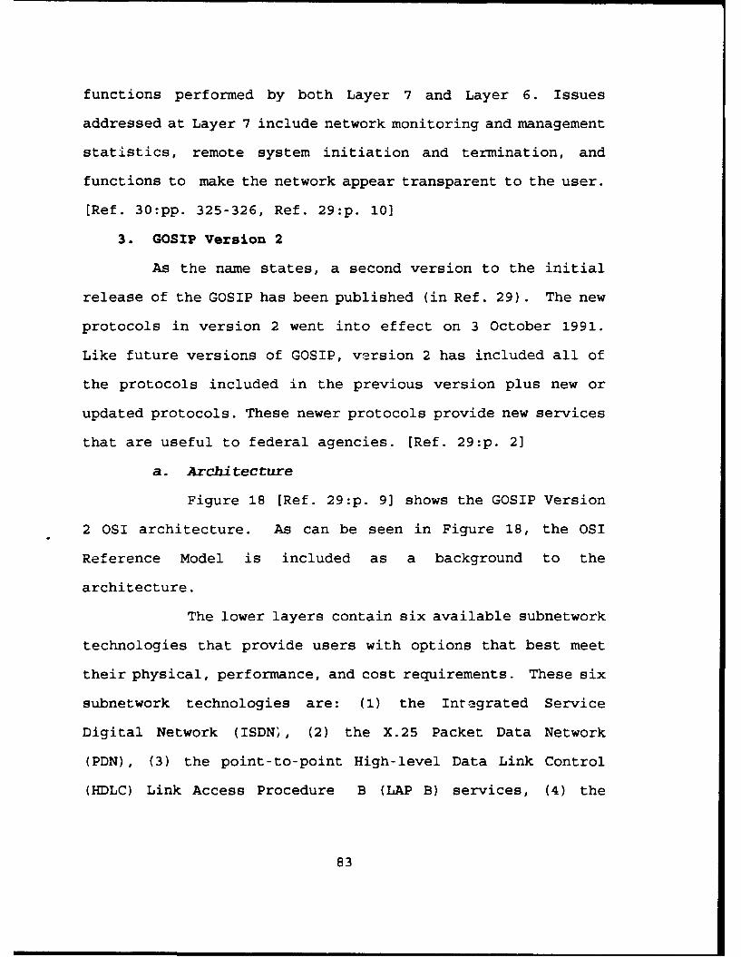
functions performed by both Layer 7 and Layer 6. Issues
addressed at Layer 7 include network monitoring and management
statistics, remote system initiation and termination, and
functions to make the network appear transparent to the user.
[Ref. 30:pp. 325-326, Ref. 29:p. 10]
3. GOSIP Version 2
As the name states, a second version to the initial
release of the GOSIP has been published (in Ref. 29). The new
protocols in version 2 went into effect on 3 October 1991.
Like future versions of GOSIP, version 2 has included all of
the protocols included in the previous version plus new or
updated protocols. These newer protocols provide new services
that are useful to federal agencies. [Ref. 29:p. 2]
a. Architecture
Figure 18 [Ref. 29:p. 9] shows the GOSIP Version
2 0SI architecture. As can be seen in Figure 18, the OSI
Reference Model is included as a background to the
architecture.
The lower layers contain six available subnetwork
technologies that provide users with options that best meet
their physical, performance, and cost requirements. These six
subnetwork technologies are: (1) the Integrated Service
Digital Network (ISDN', (2) the X.25 Packet Data Network
(PDN), (3) the point-to-point High-level Data Link Control
(HDLC) Link Access Procedure B (LAP B) services, (4) the
83

[ Oltce Document Architecture -New in GOSIP Version 2
___________ I(ODA)[j Optional protocol or service
Fie Transfer, Access and Management Virtual TerminalApl.!ain Message El (FIAM) (ISO 8571-4)(V(S901
ApLcayion Handling t VLayer . Systems
Association Control Service Element(MHS) (ISO 8650)
SesinConnectio-retdSsion -oine rsnainProtocol
Layer (1508327)
Connection -oriented Transport Protoo Connectionless Transport ProooloTransport Class 4 (ISO 8073) SO62
(ISO 88023)(SO80-)(O8025
_~S.253PacketLayer roto30
A~j.~, U Irusportand X208r)eurd[rconcint ulc es~n ytm
Figitre 18O76 LogicP Versio 2oto 0ISO Ar8hiet2r
Netwo84

Carrier Sense Multiple Access with Collision Detection
(CSMA/CD), (5) the Token-Bus, and (6) the Token-Ring. The
CSMA/CD, Token-Bus, and Token-Ring technologies are typically
used in small or local area networks (LANS), and are
controlled by the Logical Link Control (LLC). The X.25 PLP
operates in conjunction with the HDLC LAP B in either the
connection-oriented or connectionless mode. The HDLC LAP B can
also function independent of the X.25 PLP when it is operated
in the point-to-point connectionless mode. The X.25 (like the
one the Coast Guard uses) and ISDN services are typically
associated with wide area networks (WANs). [Ref. 29:pp. 7-91
GOSIP Version 2 requires the mandatory use of
connection-oriented session and transport-level protocols.
The upper layer function of interest is the X.400 MHS. The
Office Document Architecture (ODA) is considered to be above
the top level, Layer 7 (Application Layer), because it not an
OSI protocol. ODA is included in GOSIP Version 2 because "it
provides services required by federal agencies, and the
information specified by the standards can be transported by
the OSI" MHS Application layer protocols. [Ref. 29:pp. 9-101
A goal for GOSIP Version 2 is to provide guidance
for standard applications operating over networks using
standard protocols. The purchaser/user determines the
required applications and networks, and GOSIP defines required
minimum protocols. [Ref. 29:p. 10]
85

For example, the Coast Guard needs a messaging
capability over an X.25 network. GOSIP defines that the
minimum standards are the X.400 MHS, a Connection-oriented
Session Protocol, a Connection-oriented Transport Protocol, a
Connectionless Network Protocol, an X.25 Packet Layer Protocol
(PLP), an HDLC LAP B, and three options for physical-level
connections (V.35, RS-232, and RS-530) based on the
requirements for the speed of communications. Additional
requirements can be added to these to meet the needs of the
users.
This example is for a source or destination end
system (ES) that "contains the application processes that are
the ultimate sources and destinations of user oriented message
flows" and addresses all seven layers of the OSI Reference
Model [Ref. 29:p. 101. There are intermediate systems (ISs),
or interfaces (addressed in the next section), that connect
two or more networks. This type of interface typically
performs the routing and relaying of message flows, however,
GOSIP only addresses the lower three OSI Reference Model
layers for these intermediate systems. Additional
functionalities need to be specified by the purchaser/user for
these interface devices. [Ref. 29:pp. viii, 10, 12]
b. Protocols
GOSIP requires that at least one of the six lower
layer technologies/protocols and a connectionless network
86
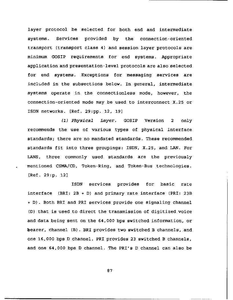
layer protocol be selected for both end and intermediate
systems. Services provided by the connection-oriented
transport (transport class 4) and session layer protocols are
minimum GOSIP requirements for end systems. Appropriate
application and presentation-level protocols are also selected
for end systems. Exceptions for messaging services are
included in the subsections below. In general, intermediate
systems operate in the connectionless mode, however, the
connection-oriented mode may be used to interconnect X.25 or
ISDN networks. [Ref. 29:pp. 12, 19]
(1) Physical Layer. GOSIP Version 2 only
recommends the use of various types of physical interface
standards; there are no mandated standards. These recommended
standards fit into three groupings: ISDN, X.25, and LAN. For
LANS, three commonly used standards are the previously
mentioned CSMA/CD, Token-Ring, and Token-Bus technologies.
[Ref. 29:p. 12]
ISDN services provides for basic rate
interface (BRI: 2B + D) and primary rate interface (PRI: 23B
+ D). Both BRI and PRI services provide one signaling channel
(D) that is used to direct the transmission of digitized voice
and data being sent on the 64,000 bps switched information, or
bearer, channel (B). BRI provides two switched B channels, and
one 16,000 bps D channel. PRI provides 23 switched B channels,
and one 64,000 bps D channel. The PRI's D channel can also be
87
used to transmit information like a B channel. [Ref. 31:pp.
382-383, Ref. 29:p. 13]
X.25 standards commonly used include the RS-
232-C, the V.35, and the RS-530. The Electronic Industries
Association (EIA) RS-232-C and the CCITT V.35 specified
physical interfaces are used for line speeds up to 19,200 bps,
and the EIA RS-530 for transfer rates over 20,000 bps. [Ref.
29:p. 13]
(2) Data Link Layer. Like the Physical Layer, the
Data Link Layer protocols can be divided into three groups:
ISDN, HDLC LAP B, and LANs. For ISDN there are two protocols
for transfer of information on the B or D channels. For the
ISDN B channel, a LAP B is used, and for the D channel, a LAP
D is used. The HDLC LAP B is used in conjunction with X.25 or
point-to-point subnetworks. For LANs, the Logical Link Control
1 is used. [Ref. 29:p. 13]
(3) Network Layer. Connectionless Network Services
(CLNS) provided by end systems are required to ensure both
local and long-haul interoperability for the federal
government. The Connectionless Network Protocol (CLNP) is the
standard. An optional standard for ISDN and X.25 services is
the combination of the Connection-oriented Network Service
(CONS) and the X.25 PLP. This is used for interoperation with
end systems (e.g., non-federal government agencies or
businesses) that do not implement the CLNP. [Ref. 29:p. 14]
88
As addressed earlier, X.25 describes the protocol governing
the interface between a computer (called a packet mode Data
Terminal Equipment (DTE)) and a packet switched network. [Ref.
31:p. 1681
(4) Transport Layer. As with the CLNS, the class
4 Connection-oriented Transport Services (COTS) provided by
end systems are required to ensure reliable end-to-end
interoperability for the federal government. The Connection-
oriented Transport Protocol is the standard. The
Connectionless Transport Service (CLTS) is also an additional
option for interoperation with non-GOSIP protocols. Transport
class 0 (per CCITT X.400 recommendations) is used in
conjunction with CONS and X.25 for connections to public data
network messaging services. [Ref. 29:pp. 10, 12, 16]
(5) Session Layer. Connection-oriented session
services are required through the use of a vendor-provided
Connection-oriented Session Protocol. Functions required by
this protocol are determined by the application layer
protocols used. [Ref. 29:p. 16]
(6) Presentation and Application Layers. These
layers are addressed together through the use of tne CCITT
X.400 MHS, which has been addressed in Chapter II. GOSIP
requires the MHS to provide all Message Transfer Services and
Interpersonal Messaging Services. [Ref. 2 9:p. 171
89
B. INTERFACE DEVICES
Before addressing DMS/CGTS interface issues, it is
important to have a basic understanding of what types of
interface devices or intermediate systems exit. In general,
interfaces include repeaters, bridges, routers, and gateways.
The following section will address these types of interface
devices with reference to the applicable OSI Reference Model
layers, then the final chapter will summarize this thesis and
address DMS/CGTS interface issues and recommendations.
1. Repeaters
Repeaters are devices that connect systems with the
same physical-level (Layer 1) protocols by regenerating
signals without changing any of the control or data
information. Repeater or amplifiers receive attenuated signals
from one link and increase the signal strength, and in some
case reconstruct digital signals, before it transmits the
signal to the next link. Repeaters are simple devices
typically used to extend the local distance limitations
(typically 500 meters) inherent in LANs. Disadvantages of the
repeater are its short distance related use and the
possibility that it may pass bad data because they do not
perform error checking functions. [Ref. 31:pp. 197-198, Ref.
30:pp. 148, 159]
90
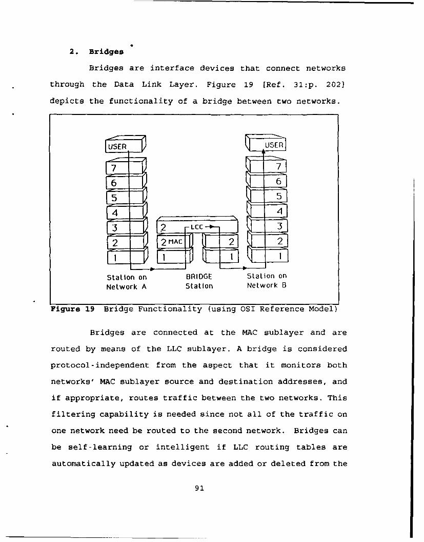
2. Bridges
Bridges are interface devices that connect networks
through the Data Link Layer. Figure 19 [Ref. 31:p. 202]
depicts the functionality of a bridge between two networks.
U SE Rf USER
7 7
6 6
5 5
44
Station on BRIDGE Station onNetwork A Station Network B
Figure 19 Bridge Functionality (using OSI Reference Model)
Bridges are connected at the MAC sublayer and are
routed by means of the LLC sublayer. A bridge is considered
protocol-independent from the aspect that it monitors both
networks' MAC sublayer source and destination addresses, and
if appropriate, routes traffic between the two networks. This
filtering capability is needed since not all of the traffic on
one network need be routed to the second network. Bridges can
be self-learning or intelligent if LLC routing tables are
automatically updated as devices are added or deleted from the
91
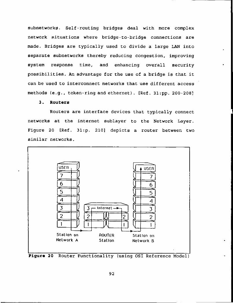
subnetworks. Self-routing bridges deal with more complex
network situations where bridge-to-bridge connections are
made. Bridges are typically used to divide a large LAN into
separate subnetworks thereby reducing congestion, improving
system response time, and enhancing overall security
possibilities. An advantage for the use of a bridge is that it
can be used to interconnect networks that use different access
methods (e.g., token-ring and ethernet). [Ref. 31:pp. 200-208]
3. Routers
Routers are interface devices that typically connect
networks at the internet sublayer to the Network Layer.
Figure 20 [Ref. 31:p. 2101 depicts a router between two
similar networks.
IUSER USERI
C-7 171
6 1 61
F5 151
3 3 F-internet-- - 3
4 2
Station on ROUTER Station onNetwork A Station Network B
Figure 20 Router Functionality (using OSI Reference Model)
92

Like bridges, routers provide filtering and other
bridging functions over a network. However, unlike bridges,
routers can be used to build large wide area networks (WANs)
by interconnecting or linking LANs to a WAN backbone, such as
an X.25 network. Unlike bridges, routers are protocol-
dependent for both the LANs and the WAN, meaning that the same
protocols need to be used. Routers also offer more imbedded
intelligence which provides enhanced network management, flow
control, and error checking capabilities. Routers keep track
of the entire network through the use of a routing table,
where it keeps track of the status of the network's nodes and
paths. For static routers, the network manager manually
maintains the routing table (s) , whereas in a dynamic router it
automatically reconfigures the routing table and recalculates
the lowest cost path, and can balance the traffic load in the
network. These extra capabilities (as compared to a bridge)
result in more effective operations due the capability to
avoid congested or inoperative links. [Ref. 31:pp. 209-2131
4. Gateways
A gateway is an interface device typically used
between two different types of networks that use different
protocols. Figure 21 [Ref. 31:p. 2101 depicts a gateway's
functionality between two dissimilar networks. Note that it
spans all seven layers to the OSI Reference Model.
93
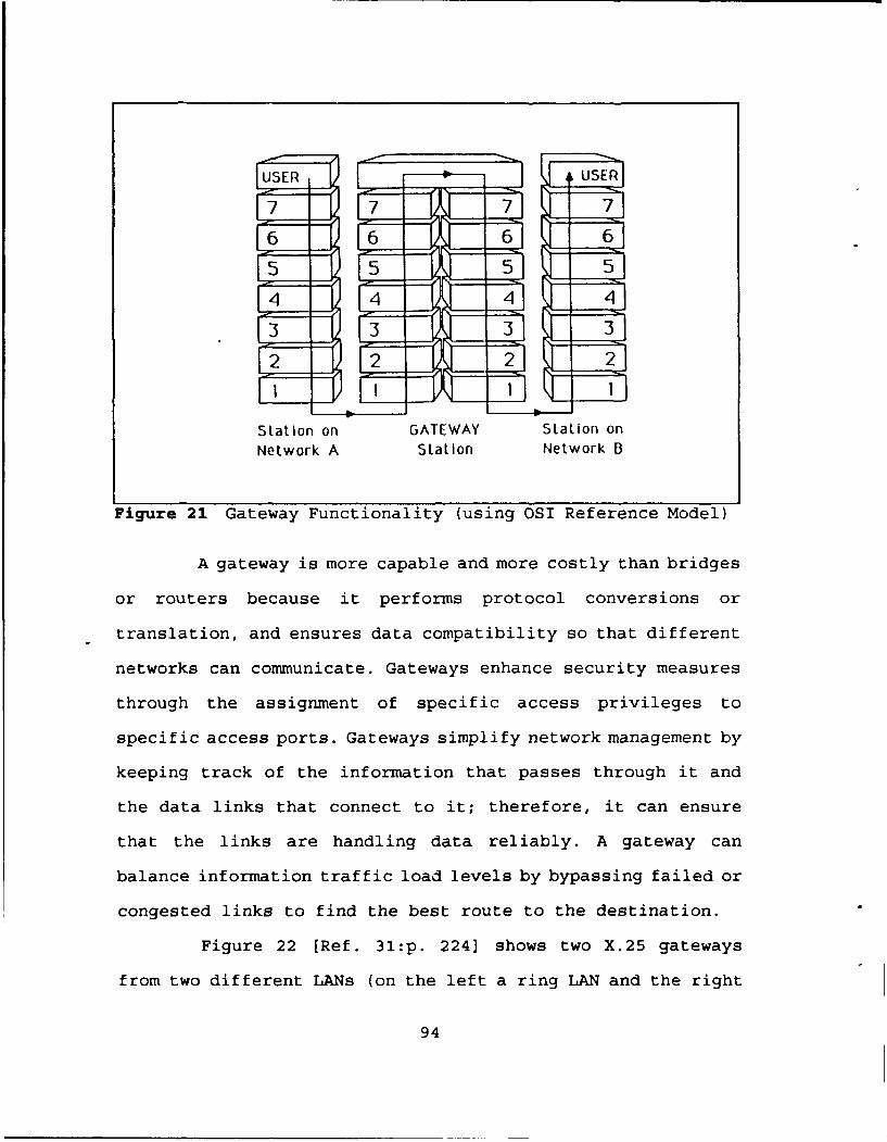
USER USER
6 16 61 6
4 14 41 4
Station on GATEWAY Station onNetwork A Station Network 6
Figure 21 Gateway Functionality (using OSI Reference Model)
A gateway is more capable and more costly than bridges
or routers because it performs protocol conversions or
translation, and ensures data compatibility so that different
networks can communicate. Gateways enhance security measures
through the assignment of specific access privileges to
specific access ports. Gateways simplify network management by
keeping track of the information that passes through it and
the data links that connect to it; therefore, it can ensure
that the links are handling data reliably. A gateway can
balance information traffic load levels by bypassing failed or
congested links to find the best route to the destination.
Figure 22 [Ref. 31:p. 224] shows two X.25 gateways
from two different LANs (on the left a ring LAN and the right
94

Public PrivateDatabacse Database
X.25
P"•ACKET SWI TCHED•
NETWORK
X.'25
X.25. Gateway
Figure 22 LAN - Gateway - PSN - Database Network
a bus LAN) connected to an X.25 Packet Switched Network, which
has access to various databases. All of these advantages
translate to a congestion or performance bottleneck due to the
extra functionalities performed at different layers. For this
reason, gateways are typically dedicated to specific
applications, such as E-Mail and batch file transfers. [Ref
31:pp. 219-2221
Bridges, routers and gateways have been summarized as
follows:
95

Bridges, routers, and gateways may be viewed asspecialized network communications servers that providevarying levels of connectivity, efficiency, and economy tocorporate networks. Each product category has widedisparities in transparency. reliability, and level ofcontrol. [Ref. 31:p. 226]
As technological advances take place, hybrid interface
devices will be developed to maximize advantages and minimize
disadvantages. One example is the hybrid bridge-router, or
brouter. A brouter distributes load sharing and alternative
routing between nodes (like a router), and also enforces
security across a network by blocking access to restricted
nodes by unauthorized users (like a bridge). Another example
is a combined router-terminal server, or trouter. A trouter is
a single device that performs the functions of a router and a
terminal server. [Ref. 31:pp. 214-215] Advances in other
network interface devices will likely evolve to meet ever-
increasing demands for networks to be more efficient and cost
effective.
96

V. SUMMARY AND CONCLUSIONS
A. SUMMARY
This thesis provides an overview of the Defense Message
System and the messaging related components of the Coast Guard
Telecommunications System. This thesis can be used as a basis
for the development of a Coast Guard DMS Transition Plan. The
DMS and the CGTS are both in the process of evolving or
transitioning to more automated systems (less manual
interventions), that will comply with appropriate standards,
such as the Government Open Systems Interface Protocol
(GOSIP). Like a fast moving target, the DMS and CGTS
transition actions complicate the task of adequately
describing the two systems, especially the CGTS. The overviews
provided in Chapters II and III attempt to address the current
communications situation, while at the same time, address
planned transition actions. The DMS and CGTS transition
actions do not simultaneously occur in all locations at the
same time. The task of system/network managers is to ensure
that both government and service needs are met, which include
compatibility and interoperability between the systems.
The DMS is a planned twenty year, three phase project to
fully automate DOD writer-to-reader messaging services by the
year 2008. It is based on the DOD's Automatic Digital Network
97
(AUTODIN) and Defense Data Network (DDN) electronic mail
services, including those services associated with DOD local
area networks. The transition to an automated system will
result in significant changes to the AUTODIN and DDN, and will
use the X.400 Message Handling Service and the X.500 Directory
Service. The automation process will evolve as the AUTODIN
message transport backbone is replaced by the base level and
long haul Information Transfer Utility, which will evolve from
the DDN and local area networks. The results of the transition
process will be seen by the closing of AUTODIN Switching
Centers, Automated Message Processing Exchanges, and
Telecommunications Centers. Appendix A lists the Coast Guard
locations that connect with these facilities. A key issue for
the Coast Guard, and other military services and DOD agencies,
is how they will interface with these DOD facilities, or their
DDN related replacement locations, during the DMS transition
process.
The automation process for the messaging components of the
Coast Guard Telecommunications System is well underway. The
Coast Guard is transitioning to a private, Coast Guard owned,
data network. This network is called the Coast Guard Data
Network which is a hybrid data network consisting of multiple
systems, networks, and transmission modes. The CGDN backbone
and its district level component will be using X.25 protocols.
The CGDN transports unclassified message and data in E-mail
envelopes. In general, classified record messages are sent
98

over AUTODIN or, for smaller units, over the Coast Guard's
Secure Data Network. The installation of the Message
Distribution Terminal (MDT) as AUTODIN Interface Terminal,
coupled with appropriate site-by-site security accreditations
for MDT installations, enhance the automation process from a
torn-paper-tape interface system, to a semi-automated, air-
gapped MDT setup, to a fully automated MDT setup. For security
purposes prior to accreditation, some Coast Guard locations
are using an air-gapped MDT setup which means that there are
no hard wired connections between the MDT and Coast Guard
systems and networks. The temporary air-gap setups require
communication center personnel to hand carry floppy diskettes
or cassette tapes between the MDT and Coast Guard systems and
networks. This situation is not as favorable as a hard wired
connection, but it is better than using torn paper-tape. With
perfect 20 - 20 hindsight, one can see that the Coast Guard's
February 1991 decision [Ref. 24] to use the U.S. Navy
originated MDT as a service-wide AUTODIN interface terminal
was on the mark, for in March 1992, the MDT became a DMS joint
project sponsored by the U.S. Air Force [Ref. 32]. For the
Coast Guard, the assignment of the DMS joint project status to
the MDT means that other services and agencies will also need
to address MDT-to-AUTODIN transition issues as the AUTODIN is
phased out.
Coast Guard plans call for the automation/closure of all
communications stations, except for one on each coast. Similar
99

automation/closure or downsizing actions are also planned for
Coast Guard communications centers. These automation/closure
and downsizing actions are similar to those planned in the DMS
Program.
Systems procured by the Coast Guard, the DOD, and other
government agencies are required to meet the Government Open
Systems Interface Protocol. GOSIP is based on Open Systems
Interface reference model and standards. This requirement was
established to ensure basic interoperability between
government agencies. This requirement will make all government
systems and networks more compatible, and will make interface
devices between them less complicated.
B. ISSUES AND RECOMMENDATIONS
This last section will address DMS related issues that may
be of interest to the Coast Guard. In general, it appears that
the actions taken or planned by the Coast Guard are heading in
the same direction as the actions planned by the DMS project.
In some ways, the Coast Guard's current use of E-Mail
"envelope" technology, to send and receive various messages
and data files as attachments to E-Mail envelopes, places the
Coast Guard in a good position to address future Coast Guard-
DMS interface issues that will be looking at similar transport
issues.
100
1. Plans for the DMS Transition
It is the opinion of the author that it may be in the
Coast Guard's best interest to document and formally address
future DMS-CGTS interface issues. Options include: (1)
continue as is without formally documenting DMS issues, (2)
include DMS transition issues in the next edition of the Coast
Guard Telecommunications Plan (Ref. 11), or (3) develop a
separate Coast Guard DMS Transition Plan. Each option has its
advantages and disadvantages.
Option 1 may appear to show that there is little Coast
Guard interest in the DMS transition process, however, Coast
Guard actions to date meet DMS objectives. For example, DMS
Phase 1 objectives are: (1) TCC automation, (2) extension of
messaging services to users, (3) transfer data pattern traffic
to DDN, (4) eliminate the use of paper material, and (5)
posture for the phasing out of communication facilities (ASCs,
AMPEs, and TTCs) through the use of transitional components
and initiating the transition to international standard
protocols and procedures [Ref. 2:p. A-i). Unilateral actions
taken by the Coast Guard meet all of these DMS goals except
for the transfer of data pattern traffic to DDN. Instead, the
Coast Guard is transitioning unclassified data pattern traffic
to the CGDN. It may be in the Coast Guard's best interest to
be aware of the changes that occur to DDN as it evolves to the
ITU. This point is brought up as it may be more cost effective
to use the ITU in the future rather than maintain a separate
101
CGDN, or maybe the Coast Guard could plan for the CGDN to
evolve and become part of the ITU. An advantage of a separate
CGDN is that it would not be restricted by DOD related
Minimize conditions. For example, DOD Minimize actions were
used during the 1990-1991 operations Desert Shield and Desert
Storm. The Coast Guard used this time period to enforce the
restriction on sending messages over the AUTODIN by requiring
all unclassified messages (where possible) to be sent over the
CGDN. Because of the availability and capabilities of the
CGDN, Coast Guard day-to-day operations were not substantially
affected by the DOD Minimize actions.
Option 2's advantage is that specific Coast Guard-DMS
transition issues could be folded into the Coast Guard-wide
communications plan, or have a separate dedicated chapter,
without having to develop a separate plan. Disadvantages could
possibly include that some transition issues may be overlooked
or not fully considered or addressed, or the status of the
transition issues may not be properly maintained over time.
Option 3's advantage is that all CGTS-DMS transition
issues would be consolidated into one document that could be
easily used by both the Coast Guard and the DMS community. The
Coast Guard DMS Transition Plan could then be targeted for
updates every other year or possibly even annually. A
disadvantage would be the extra Coast Guard Headquarters staff
time that would need to be devoted to developing and
maintaining the plan. It is the author's opinion that the
102
time dedicated to accomplishing this task (and maintain it)
would pay off in future benefits by providing the DMS
community with Coast Guard inputs and possible new ideas and
recommendations for the evolving DMS, while at the same time
providing the Coast Guard with DMS related policy and
guidance. Based on this option's advantage, the author
recommends the development of a Coast Guard DMS Transition
Plan that focuses primarily on CGTS-DMS interface related
issues.
2. Other Specific Issues
The following paragraphs address some of the important
issues that should be considered by the Coast Guard. Although
not all-inclusive, these issues represent items of interest
that the author considers worthy of near term Coast Guard
attention.
a. X.400 MHS and X.500 Directozy
The X.400 Message Handling Service is a GOSIP
standard that will be used by the DMS. The Coast Guard
currently has the capability to utilize X.400 capabilities
through the use of Unisys's OFIS Mail (B-Mail), the OFIS
Access - X.400 system service, and the BTOS OSI MHS 400 system
[Ref. 33:p. H-1]. Depending on the next CGSW contract and the
costs involved, the Coast Guard should consider transition E-
Mail services to use the X.400 MHS to meet GOSIP and DMS
standards. X.500 Directory related issues are planned to be
103

addressed in GOSIP Version 3 [Ref. 29:p. 41), and it is also
included in DMS plans. The Coast Guard should consider the use
of this standard also. By having X.400 and X.500 capabilities,
the Coast Guard could position itself to meet future DMS
transition needs. If these capabilities are not available to
the Coast Guard when the DMS phases out AUTODIN components,
then a transitional interface component will need to be
developed. An example of this is the DMS's Phase 2 DIN/DMS
Gateway.
b. DMS-CGTS Interface
One of the most important issues is the interface
between the DMS and the CGTS. That current interface device is
the MDT connection to the AUTODIN. (AUTODIN is a DMS baseline
component.) As addressed above, other services and agencies
will also be looking to transition from the MDT-to-AUTODIN
connection to a future connection between their follow-on
components. This transition should be addressed from a Coast
Guard service-wide perspective and also by each Coast Guard
location listed in Appendix A. The service-wide perspective
should address overall policy, guidance, and funding on how to
manage the transition. Coast Guard locations that currently
connect to AUTODIN must be preparing for the day when those
connections will need to be modified or replaced. The Coast
Guard locations in Appendix A should maintain close contact
104

with their appropriate ASC, AMPE, or TCC to ensure that they
are kept informed of future planned changes.
c. Security Issues
There are numerous DMS related security issues.
Where appropriate, the security requirements of the Coast
Guard, DOD, and National Security Agency need to be met. One
such issue is the site specific accreditations to install
direct MDT connections without an air-gap. DMS security
policies will identify a Message Security Protocol (MSP) or
other security mechanisms. A DMS Component Security Guide will
contain policy on how to certify DMS components and accredit
facilities. The Coast Guard will likely have the option to
adopt the MSP standard for Coast Guard use, or use different
standards and use an MSP gateway to interface with the DMS. An
advantage of using the MSP is that the Coast Guard would have
less complicated interfaces to the DMS. These and
other security related issues should be addressed by the
Coast Guard.
d. Coast Guard Support to DOD
As addressed in Chapter I, the Coast Guard
provides messaging support to various DOD and military service
commands, units, and agencies, such as Joint Task Force 5 and
many others. A detailed inventory of all of these commands,
units, and agencies should be provided to the DMS Project and
appropriate military services for their DMS Transition Plans.
105
As Coast Guard systems are automated, so should the messaging
support to those commands, units, and agencies, or this
support should be replaced by systems provided by the DOD
and/or appropriate military service or agency.
106

APPENDIX A. COAST GUARD AUTODIN ACCESS
Coast Guard Locations ASC/AMPE/TCC Access Locations
Headquarters, Washington, DC NTCC Cheltenham, MD
Atlantic Area, New York, NY ASC Hancock, NY
1st District, Boston, MA ASC Hancock, NY
2nd District, St Louis, MO ASC Tinker AFB
5th District, Portsmouth, VA NTCC Breezy Point, NC
7th District, Miami, FL ASC Albany, NY
GANTSEC, San Juan, PR NAVCOMMSTA R. Roads, PR
9th District, Cleveland, OH ASC Gentile AFB
CAMSLANT, Chesapeake, VA NTCC Breezy Point, NC
COMMSTA Boston, MA ASC Ft Dietrick, MD
COMMSTA Miami, FL ASC Albany, NY
Group Baltimore, MD ASC Andrew AFB
AIRSTA Elizabeth City, NC ASC Ft Dietrick, MD
Pacific Area, Alameda, CA AMME Oakland, CA
11th District Long Beach, CA ASC Norton AFB
13th District, Seattle, WA NAVCOMMSTA Puget Sound, WA
14th District, Honolulu, HI NTCC Makalapa, HI
17th District, Juneau, AK ASC McClellan AFB
CAMSPAC, Point Reyes, CA NTCC Stockton, CA
COMMSTA Honolulu, HI NTCC Makalapa, HI
COMMSTA Kodiak, AK ASC McClellan AFB
COMMSTA Guam NAVCAMS WESTPAC Guam
107
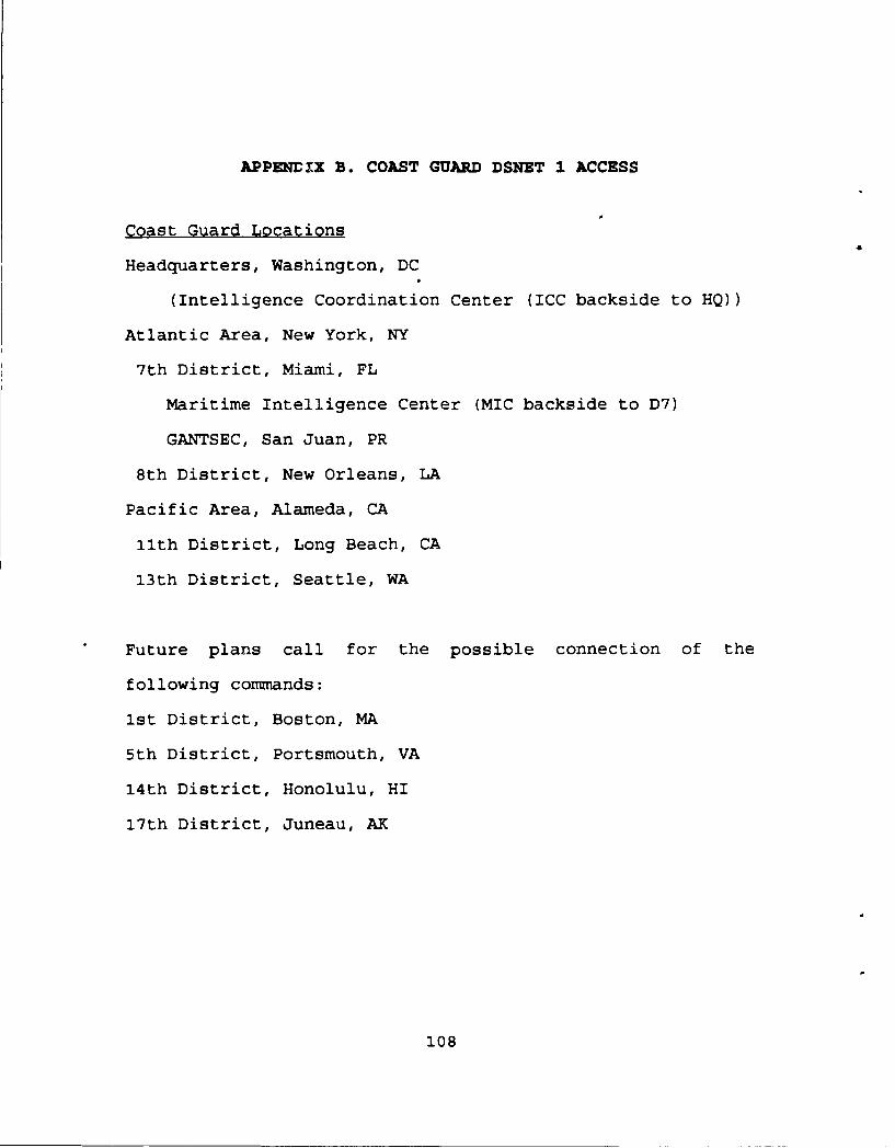
APPENDrX B. COAST GUARD DSNET 1 ACCESS
Coast Guard Locations
Headquarters, Washington, DC
(Intelligence Coordination Center (ICC backside to HQ))
Atlantic Area, New York, NY
7th District, Miami, FL
Maritime Intelligence Center (MIC backside to D7)
GANTSEC, San Juan, PR
8th District, New Orleans, LA
Pacific Area, Alameda, CA
11th District, Long Beach, CA
13th District, Seattle, WA
Future plans call for the possible connection of the
following commands:
1st District, Boston, MA
5th District, Portsmouth, VA
14th District, Honolulu, HI
17th District, Juneau, AK
108

LIST OF REFERENCES
1. U.S. Government, United States Code (USC). Title 14 - U.S.Coast Guard, Volume 5, Government Printing Office, 1988.
2. Department of Defense, The Defense Message System (DMS)Target Architecture (TAIS), 13 February 1991.
3. Joint Chiefs of Staff, Memorandum MJCS-20-89,Implementation of Multicommand Required OperationalCapability (MROC) 3-88, the Defense Message System (DMS),6 February 1989.
4. Sippl, C. J., The New Webster's Computer Terms, LexiconPublishing, Inc., 1990.
5. Allied Communications Publication (ACP) 167(F), Glossaryof Communications - Electronic Terms, April 1981.
6. Defense Data Network, Network Information Center, SRIInternational, DDN New User Guide (NIC 6001), 2nd Edition,February 1991.
7. Department of the Navy, Defense Message System TransitionPlan Draft, January 1991.
8. The Defense Data Network. High Capacity for DOD DataTransmission, April 1986.
9. U.S. Coast Guard, Commandant Instruction M5400.7C, TheCoast Guard Organization Manual, 4 August 1989, with CH-1of 21 May 1990.
10. U.S. Coast Guard, Commandant Instruction M2000.3B,Telecommunications Manual (TCM), 4 April 1988, with CH-1of 23 April 1991.
11. U.S. Coast Guard, Commandant Instruction M2000.4A, CoastGuard Telecommunications Plan (TCP), 20 April 1988.
12. U.S. Coast Guard, Office of Command, Control andCommunications, U. S. Coast Guard TelecommunicationsArchitecture, February 1991.
13. U.S. Coast Guard, Commandant Instruction 5270.1B,Management of Electronic Mail, 30 March 1990.
109
14. Federal Systems Integration and Management Center(FEDSIM), Final U.S. Coast Guard Standard WorkstationRequirements Analysis (90058-02-DOT), May 1991.
15. U.S. Coast Guard, Office of Conmnand, Control andCommunications (G-T), T Staff Notes, What is the HybridData Network?, 15 October 1991.
16. U.S. Coast Guard, Office of Command, Control andCommunications (G-T), T Staff Notes, CTOS 3.3 Evaluations,13 December 1991.
17. U.S. Coast Guard, Information Systems Center, Coast GuardStandard Semi-Automated Message Processing System. CGSWSSAMPS Concept of Operations, September 1991.
18. Unisys Corporation, BTOS Series Software ReleaseInformation File for BTOS X.25 Gateway, Software Release9.1, undated.
19. U.S. Coast Guard, Information Systems Center, ReleaseNotice for X.25 Communications Manager 2.04, 23 January1991.
20. U.S. Coast Guard, Commander, Thirteenth Coast GuardDistrict Instruction M2070, Implementation and Operationof the Coast Guard Data Network (CGDN) within the ThirteenDistrict, 4 November 1991.
21. U.S. Coast Guard, Coast Guard Data Network, 8 November1991.
22. Patton, R, CWO, USCG, Electronic Mail ID N08000057338,Subject: MDT Info, 15 January 1992.
23. U.S. Coast Guard, Office of Command, Control, andCommunications (G-T), T Staff Notes, E-Mail NamingStandards, 31 March 1992.
24. U.S. Coast Guard, Commandant (G-TTS), Memorandum 2070 Ser:21034, Subject: MDT Decision Paper, 7 February 1991, withCommandant (G-T) endorsement of 25 February 1991.
25. Telephone conversation between C. Bremner, RMI, USCG, U.S.Coast Guard Pacific Area (Pt) and the author, 10 April1992.
26. Zenith/INTEQ, Inc. Pamphlet, The Communications Platform,Message Distribution Terminal on a Desktop, 1989.
110
27. Telephone Conversation between J. Gallagher, LT, USCG,U.S. Coast Guard Headquarters (G-T) and the author, 16March 1992.
28. ARINC Research Corporation, Proceedings of the G-TTelecommunications Conference. 25-27 March 1991, undated.
29. U.S. Department of Commerce, Federal InformationProcessing Standards Publication 146-1, Government OpenSystems Interconnection Profile (GOSIP), 3 April 1991.
30. Fitzgerald, J., Business Data Communications: BasicConcepts, Security, and Design, 3rd Edition, John Wiley &Sons, 1990.
31. Muller, N. J. and Davidson, R. P., LANs to WANs: NetworkManagement for the 1990s, Artech House, 1990.
32. Zenith/INTEQ Inc., News Release, Defense Message SystemApproves AUTODIN Terminal by Zenith/INTEO, 20 March 1992.
33. Unisys Corporation, BTOS OFIS Mail: Administration Guide,March 1989.
ii
nmnnnnm111
INITIAL DISTRIBUTION LIST
I. Defense Technical Information Center 2Cameron StationAlexandria, VA 22304-6145
2. Library, Code 052 2Naval Postgraduate SchoolMonterey, CA 93943-5002
3. Commandant (G-T) 2U.S. Coast Guard2100 Second Street, S.W.Washington, DC 20593-0001
4. DirectorDefense Information Systems AgencyCode DISMWashington, DC 20305-2000
5. DirectorNaval Telecommunications AutomationSupport Centerc/o NAVCOMMUNIT WashingtonAttn: Code 44Washington, DC 20397-5310
6. Commander (At)Atlantic Area, U.S. Coast GuardGovernors IslandNew York, NY 10004-5000
7. Commander (Pt)Pacific Area, U.S. Coast GuardCoast Guard IslandAlameda, CA 94501-5100
8. Commanding Officer 1U.S. Coast Guard Information Center7323 Telegraph RoadAlexandria, VA 22310-3999
9. Commander (dttm) 1Thirteenth Coast Guard District915 2nd AvenueSeattle, WA 98174-1067
112

10. Professor Dan C. Boger, Code AS/BoNaval Postgraduate SchoolMonterey, CA 93943-5000
11. CDR Allan W. Tulloch, USN, Code AS/TuNaval Postgraduate SchoolMonterey, CA 93943-5000
12. LCDR John J. Lapke196 First AvenueStratford, CT 06497-0000
113