naval postgraduate school - auvac · naval postgraduate school monterey, california . thesis ....
TRANSCRIPT
NAVAL
POSTGRADUATE SCHOOL
MONTEREY, CALIFORNIA
THESIS
Approved for public release; distribution is unlimited
AN ANALYSIS OF UNDERSEA GLIDER ARCHITECTURES AND AN ASSESSMENT OF
UNDERSEA GLIDER INTEGRATION INTO UNDERSEA APPLICATIONS
by
William P.Barker
September 2012
Thesis Advisor: John Osmundson Second Reader: Steven Bousquet

THIS PAGE INTENTIONALLY LEFT BLANK
i
REPORT DOCUMENTATION PAGE Form Approved OMB No. 0704-0188 Public reporting burden for this collection of information is estimated to average 1 hour per response, including the time for reviewing instruction, searching existing data sources, gathering and maintaining the data needed, and completing and reviewing the collection of information. Send comments regarding this burden estimate or any other aspect of this collection of information, including suggestions for reducing this burden, to Washington headquarters Services, Directorate for Information Operations and Reports, 1215 Jefferson Davis Highway, Suite 1204, Arlington, VA 22202-4302, and to the Office of Management and Budget, Paperwork Reduction Project (0704-0188) Washington DC 20503. 1. AGENCY USE ONLY (Leave blank)
2. REPORT DATE September 2012
3. REPORT TYPE AND DATES COVERED Master’s Thesis
4. TITLE AND SUBTITLE An Analysis of Undersea Glider Architectures and an Assessment of Undersea Glider Integration into Undersea Applications
5. FUNDING NUMBERS
6. AUTHOR(S) William P. Barker 7. PERFORMING ORGANIZATION NAME(S) AND ADDRESS(ES)
Naval Postgraduate School Monterey, CA 93943-5000
8. PERFORMING ORGANIZATION REPORT NUMBER
9. SPONSORING /MONITORING AGENCY NAME(S) AND ADDRESS(ES) N/A
10. SPONSORING/MONITORING AGENCY REPORT NUMBER
11. SUPPLEMENTARY NOTES The views expressed in this thesis are those of the author and do not reflect the official policy or position of the Department of Defense or the U.S. Government. IRB Protocol number ___N/A____.
12a. DISTRIBUTION / AVAILABILITY STATEMENT Approved for public release; distribution is unlimited.
12b. DISTRIBUTION CODE A
13. ABSTRACT (maximum 200 words)
Currently, buoyancy driven underwater gliders are deployed globally to gather oceanographic data from across the world’s oceans. This thesis examines the utility of underwater gliders within the context of providing additional U.S. Navy capabilities. An extensive survey of available underwater gliders was undertaken and the resultant survey pool of ten gliders down selected to five gliders of fixed wing configuration. A comprehensive architectural analysis was then conducted of seven key architectural attributes of the five selected gliders. The architectural analysis compared various implementations of the key architectural attributes relative to desirable traits and capabilities for a notional U.S. Navy glider. Following the architectural analysis a proposed architecture for a U.S. Navy underwater glider was developed which includes a compendium of ‘best’ features gleaned from the architectural analysis. Drivers and rationale for selection of specific key architectural attributes and features are also provided. Additionally, a comparison of constraints and capabilities of underwater gliders is provided. Finally, a comparison of the current and proposed capabilities of underwater gliders versus other Autonomous Undersea Vehicles, specifically Unmanned Undersea Vehicles, is proffered.
14. SUBJECT TERMS underwater glider, unmanned undersea vehicle (UUV), autonomous undersea vehicle (AUV), system architecture, underwater glider survey, architectural attributes, underwater glider recommendation for U.S. Navy, underwater glider system analysis
15. NUMBER OF PAGES
91 16. PRICE CODE
17. SECURITY CLASSIFICATION OF REPORT
Unclassified
18. SECURITY CLASSIFICATION OF THIS PAGE
Unclassified
19. SECURITY CLASSIFICATION OF ABSTRACT
Unclassified
20. LIMITATION OF ABSTRACT
UU NSN 7540-01-280-5500 Standard Form 298 (Rev. 8-98) Prescribed by ANSI Std. Z39.18

ii
THIS PAGE INTENTIONALLY LEFT BLANK
iii
Approved for public release; distribution is unlimited
AN ANALYSIS OF UNDERSEA GLIDER ARCHITECTURES AND AN ASSESSMENT OF UNDERSEA GLIDER INTEGRATION INTO UNDERSEA
APPLICATIONS
William P. Barker Civilian, Department of the Navy
B.S., University of Rhode Island, 1983
Submitted in partial fulfillment of the requirements for the degree of
MASTER OF SCIENCE IN SYSTEMS ENGINEERING
from the
NAVAL POSTGRADUATE SCHOOL September 2012
Author: William P. Barker
Approved by: John S. Osmundson Thesis Advisor
Steven Bousquet Second Reader
Clifford Whitcomb Chair, Department of Systems Engineering

iv
THIS PAGE INTENTIONALLY LEFT BLANK
v
ABSTRACT
Currently, buoyancy driven underwater gliders are deployed globally to gather
oceanographic data from across the world’s oceans. This thesis examines the
utility of underwater gliders within the context of providing additional U.S. Navy
capabilities. An extensive survey of available underwater gliders was undertaken
and the resultant survey pool of ten gliders down selected to five gliders of fixed
wing configuration. A comprehensive architectural analysis was then conducted
of seven key architectural attributes of the five selected gliders. The
architectural analysis compared various implementations of the key architectural
attributes relative to desirable traits and capabilities for a notional U.S. Navy
glider. Following the architectural analysis a proposed architecture for a U.S.
Navy underwater glider was developed which includes a compendium of ‘best’
features gleaned from the architectural analysis. Drivers and rationale for
selection of specific key architectural attributes and features are also provided.
Additionally, a comparison of constraints and capabilities of underwater gliders is
provided. Finally, a comparison of the current and proposed capabilities of
underwater gliders versus other Autonomous Undersea Vehicles, specifically
Unmanned Undersea Vehicles, is proffered.

vi
THIS PAGE INTENTIONALLY LEFT BLANK
vii
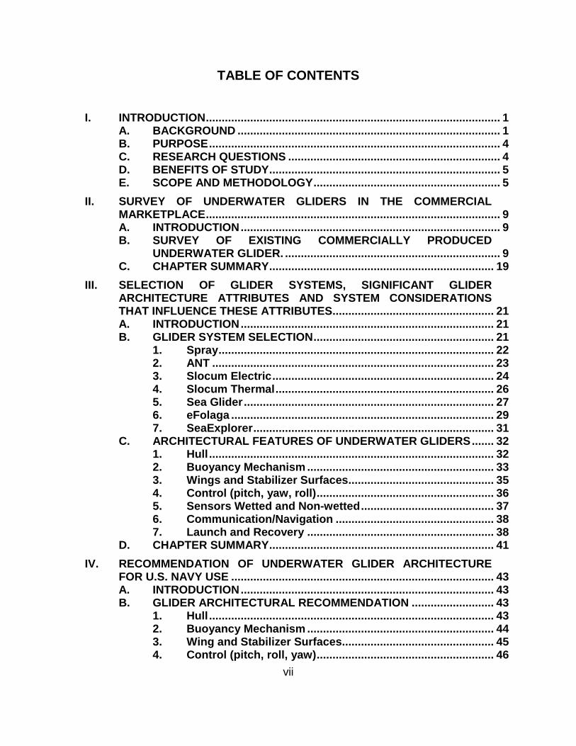
TABLE OF CONTENTS
I. INTRODUCTION ............................................................................................. 1 A. BACKGROUND ................................................................................... 1 B. PURPOSE ............................................................................................ 4 C. RESEARCH QUESTIONS ................................................................... 4 D. BENEFITS OF STUDY ......................................................................... 5 E. SCOPE AND METHODOLOGY ........................................................... 5
II. SURVEY OF UNDERWATER GLIDERS IN THE COMMERCIAL MARKETPLACE ............................................................................................. 9 A. INTRODUCTION .................................................................................. 9 B. SURVEY OF EXISTING COMMERCIALLY PRODUCED
UNDERWATER GLIDER. .................................................................... 9 C. CHAPTER SUMMARY ....................................................................... 19
III. SELECTION OF GLIDER SYSTEMS, SIGNIFICANT GLIDER ARCHITECTURE ATTRIBUTES AND SYSTEM CONSIDERATIONS THAT INFLUENCE THESE ATTRIBUTES ................................................... 21 A. INTRODUCTION ................................................................................ 21 B. GLIDER SYSTEM SELECTION ......................................................... 21
1. Spray ....................................................................................... 22 2. ANT ......................................................................................... 23 3. Slocum Electric ...................................................................... 24 4. Slocum Thermal ..................................................................... 26 5. Sea Glider ............................................................................... 27 6. eFolaga ................................................................................... 29 7. SeaExplorer ............................................................................ 31
C. ARCHITECTURAL FEATURES OF UNDERWATER GLIDERS ....... 32 1. Hull .......................................................................................... 32 2. Buoyancy Mechanism ........................................................... 33 3. Wings and Stabilizer Surfaces .............................................. 35 4. Control (pitch, yaw, roll) ........................................................ 36 5. Sensors Wetted and Non-wetted .......................................... 37 6. Communication/Navigation .................................................. 38 7. Launch and Recovery ........................................................... 38
D. CHAPTER SUMMARY ....................................................................... 41
IV. RECOMMENDATION OF UNDERWATER GLIDER ARCHITECTURE FOR U.S. NAVY USE ................................................................................... 43 A. INTRODUCTION ................................................................................ 43 B. GLIDER ARCHITECTURAL RECOMMENDATION .......................... 43
1. Hull .......................................................................................... 43 2. Buoyancy Mechanism ........................................................... 44 3. Wing and Stabilizer Surfaces ................................................ 45 4. Control (pitch, roll, yaw) ........................................................ 46
viii
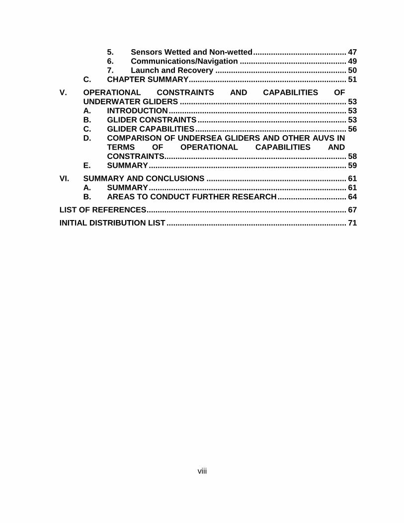
5. Sensors Wetted and Non-wetted .......................................... 47 6. Communications/Navigation ................................................ 49 7. Launch and Recovery ........................................................... 50
C. CHAPTER SUMMARY ....................................................................... 51
V. OPERATIONAL CONSTRAINTS AND CAPABILITIES OF UNDERWATER GLIDERS ........................................................................... 53 A. INTRODUCTION ................................................................................ 53 B. GLIDER CONSTRAINTS ................................................................... 53 C. GLIDER CAPABILITIES .................................................................... 56 D. COMPARISON OF UNDERSEA GLIDERS AND OTHER AUVS IN
TERMS OF OPERATIONAL CAPABILITIES AND CONSTRAINTS.................................................................................. 58
E. SUMMARY ......................................................................................... 59
VI. SUMMARY AND CONCLUSIONS ............................................................... 61 A. SUMMARY ......................................................................................... 61 B. AREAS TO CONDUCT FURTHER RESEARCH ............................... 64
LIST OF REFERENCES .......................................................................................... 67
INITIAL DISTRIBUTION LIST ................................................................................. 71
ix
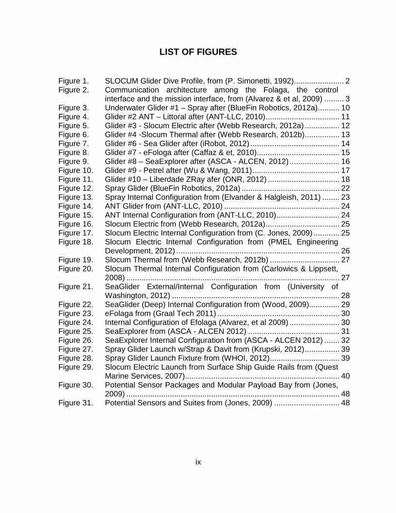
LIST OF FIGURES
Figure 1. SLOCUM Glider Dive Profile, from (P. Simonetti, 1992) ....................... 2 Figure 2. Communication architecture among the Folaga, the control
interface and the mission interface, from (Alvarez & et al, 2009) ......... 3 Figure 3. Underwater Glider #1 – Spray after (BlueFin Robotics, 2012a) .......... 10 Figure 4. Glider #2 ANT – Littoral after (ANT-LLC, 2010) .................................. 11 Figure 5. Glider #3 - Slocum Electric after (Webb Research, 2012a) ................ 12 Figure 6. Glider #4 -Slocum Thermal after (Webb Research, 2012b) ................ 13 Figure 7. Glider #6 - Sea Glider after (iRobot, 2012) ......................................... 14 Figure 8. Glider #7 - eFologa after (Caffaz & et, 2010) ...................................... 15 Figure 9. Glider #8 – SeaExplorer after (ASCA - ALCEN, 2012) ....................... 16 Figure 10. Glider #9 - Petrel after (Wu & Wang, 2011) ........................................ 17 Figure 11. Glider #10 – Liberdade ZRay afer (ONR, 2012) ................................. 18 Figure 12. Spray Glider (BlueFin Robotics, 2012a) ............................................. 22 Figure 13. Spray Internal Configuration from (Elvander & Halgleish, 2011) ........ 23 Figure 14. ANT Glider from (ANT-LLC, 2010) ..................................................... 24 Figure 15. ANT Internal Configuration from (ANT-LLC, 2010) ............................. 24 Figure 16. Slocum Electric from (Webb Research, 2012a) .................................. 25 Figure 17. Slocum Electric Internal Configuration from (C. Jones, 2009) ............ 25 Figure 18. Slocum Electric Internal Configuration from (PMEL Engineering
Development, 2012) ........................................................................... 26 Figure 19. Slocum Thermal from (Webb Research, 2012b) ................................ 27 Figure 20. Slocum Thermal Internal Configuration from (Carlowics & Lippsett,
2008) .................................................................................................. 27 Figure 21. SeaGlider External/Internal Configuration from (University of
Washington, 2012) ............................................................................. 28 Figure 22. SeaGlider (Deep) Internal Configuration from (Wood, 2009) .............. 29 Figure 23. eFolaga from (Graal Tech 2011) ........................................................ 30 Figure 24. Internal Configuration of Efolaga (Alvarez, et al 2009) ....................... 30 Figure 25. SeaExplorer from (ASCA - ALCEN 2012) .......................................... 31 Figure 26. SeaExplorer Internal Configuration from (ASCA - ALCEN 2012) ....... 32 Figure 27. Spray Glider Launch w/Strap & Davit from (Krupski, 2012) ................ 39 Figure 28. Spray Glider Launch Fixture from (WHOI, 2012) ................................ 39 Figure 29. Slocum Electric Launch from Surface Ship Guide Rails from (Quest
Marine Services, 2007) ....................................................................... 40 Figure 30. Potential Sensor Packages and Modular Payload Bay from (Jones,
2009) .................................................................................................. 48 Figure 31. Potential Sensors and Suites from (Jones, 2009) .............................. 48

x
THIS PAGE INTENTIONALLY LEFT BLANK

xi
LIST OF TABLES
Table 1. Recommended Architecture for U.S. Navy Underwater Glider ........... 52

xii
THIS PAGE INTENTIONALLY LEFT BLANK
xiii
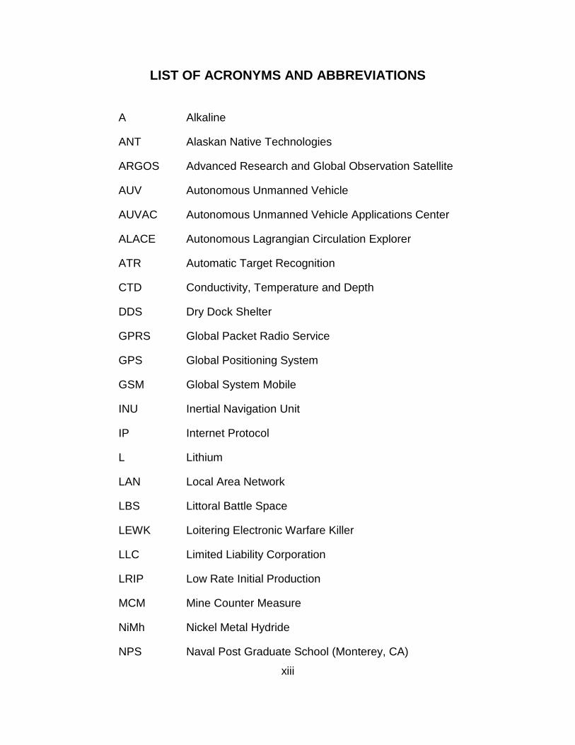
LIST OF ACRONYMS AND ABBREVIATIONS
A Alkaline
ANT Alaskan Native Technologies
ARGOS Advanced Research and Global Observation Satellite
AUV Autonomous Unmanned Vehicle
AUVAC Autonomous Unmanned Vehicle Applications Center
ALACE Autonomous Lagrangian Circulation Explorer
ATR Automatic Target Recognition
CTD Conductivity, Temperature and Depth
DDS Dry Dock Shelter
GPRS Global Packet Radio Service
GPS Global Positioning System
GSM Global System Mobile
INU Inertial Navigation Unit
IP Internet Protocol
L Lithium
LAN Local Area Network
LBS Littoral Battle Space
LEWK Loitering Electronic Warfare Killer
LLC Limited Liability Corporation
LRIP Low Rate Initial Production
MCM Mine Counter Measure
NiMh Nickel Metal Hydride
NPS Naval Post Graduate School (Monterey, CA)
xiv
NOAA National Oceanographic and Atmospheric Association
ONR Office of Naval Research
REA Rapid Environmental Assessment
REMUS Remote Environmental Monitoring Unit System
RF Radio Frequency
RIB Rigged Inflatable Boat
SVP Sound Velocity Profile
TCP Transmission Control Protocol
UHF Ultra High Frequency
UK United Kingdom
U.S. United States
USS United States Ship
UUV Unmanned Undersea Vehicle
WHOI Woods Hole Oceanographic Institute
xv
EXECUTIVE SUMMARY
This thesis examines the utility of underwater gliders within the context of
providing additional U.S. Navy capabilities. A notional architecture for a U.S.
Navy glider is proposed based on an extensive survey of available underwater
gliders and a rigorous analysis of desirable key architectural attributes. The
resultant, proposed, U.S. Navy underwater glider architecture includes: seawater
compressibility matched composite hull, forward and aft wetted sections, two
pump buoyancy system, aft swept fixed wings at 45 degrees, pitch control by
buoyancy change and internal weight movement, yaw control by actuated vertical
stabilizer (with embedded antenna), standard sensor suite of
Conductivity/Temperature/Depth (CTD)/compass/altitude, separate sensor
payload bay with fixed interfaces, structural features allowing launch/recovery
from surface craft and submarine payload tubes.
With a notional architecture of the proposed U.S. Navy glider established,
a comparison of constraints and capabilities of underwater gliders was
undertaken. The limiting constraint is the need to intermittently surface to
transmit data and receive tasking instructions. The dominant capability is the
ability to maintain a persistent presence in a given operating area as a result of
the underwater glider’s significant endurance capability. Finally, a comparison of
the current and proposed capabilities of underwater gliders versus other
Autonomous Undersea Vehicles (AUV), specifically Unmanned Undersea
Vehicles (UUVs), is conducted. This comparison results in the recommendation
to use a fleet of underwater gliders as a U.S. coastal protection trip-wire system
or as detection and tracking vehicles for locating threat patrol submarines.

xvi
THIS PAGE INTENTIONALLY LEFT BLANK

xvii
ACKNOWLEDGMENTS
I would like to express my gratitude to Professor John Osmundson for
providing his enthusiasm and promptness of review of my draft materials during
this thesis effort and also to Mr. Steven Bousquet for freely volunteering to act as
Second Reader.
Lastly I would like to thank my family for allowing me to pursue an
advanced degree given our intensive schedule demands.

xviii
THIS PAGE INTENTIONALLY LEFT BLANK
1
I. INTRODUCTION
A. BACKGROUND
Unmanned Autonomous Vehicles (AUVs) for the undersea domain have
taken many forms in the past decades. AUV capability, and particularly
autonomy, of these devices have increased significantly as AUV technology has
evolved. AUV underwater devices range from simple data gathering devices to
highly sophisticated Unmanned Undersea Vehicles (UUVs). An example of a
data-gathering device is the SeaBird Electronics, ALACE (Autonomous
Lagrangian Circulation Explorer) float (Seabird Inc., 16 Apr, 2012), which reports
temperature, salinity and drift data from the world’s oceans via satellite to the
ARGOS (Advanced Research and Global Observation Satellite) satellite network.
While an example of a highly sophisticated UUV is the Remote Environmental
Measuring Unit (REMUS) (Kongsberg Maritime, 2012) used for debris field
mapping, environmental monitoring and search and salvage operations.
Between the simple data gathering devices and highly sophisticated
UUVs, exists a class of vehicle known as underwater gliders. Although many
attribute the idea for underwater gliders to Henry Strommel from his fictional work
(Strommel, 1989), underwater gliders were originally the vision of Douglas Webb,
the founder of Webb Research, Falmouth, MA. The underwater glider concept
was to conduct, controllable, mobile, measurements of conductivity, temperature
and salinity in the world’s oceans. This is in direct contrast to the ALACE floats,
which inherently follow the path of the ocean’s current. Underwater gliders
function by changing buoyancy to move up and down vertically while fixed wings
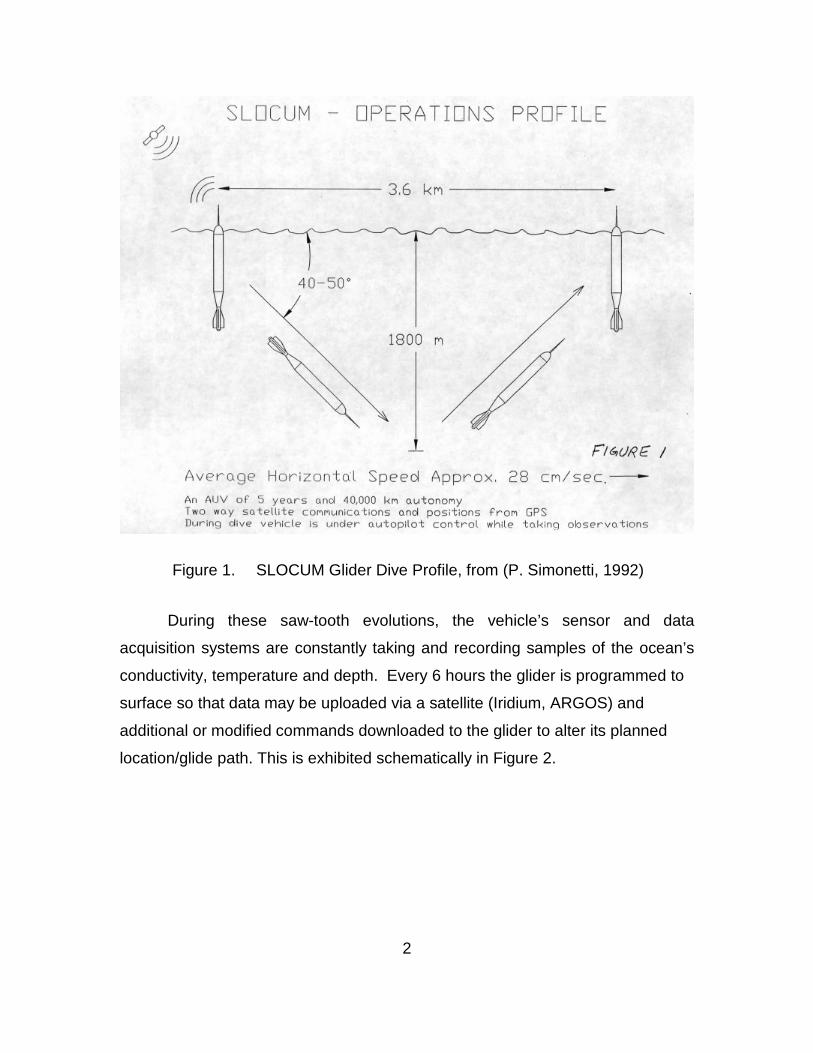
turn vertical motion into horizontal motion. A typical trajectory of an underwater
glider is shown in Figure 1. The trajectory is ‘saw-tooth’ in nature as the glider
repetitively descends and ascends the ocean environment.
2
Figure 1. SLOCUM Glider Dive Profile, from (P. Simonetti, 1992)
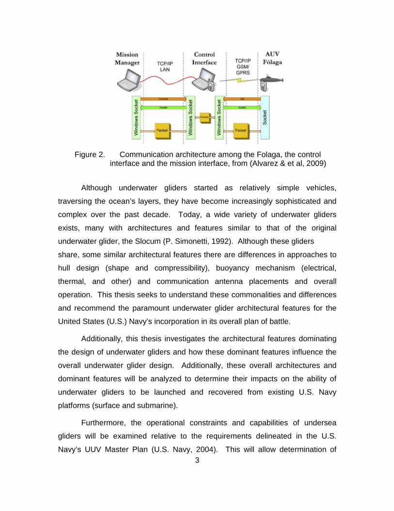
During these saw-tooth evolutions, the vehicle’s sensor and data
acquisition systems are constantly taking and recording samples of the ocean’s
conductivity, temperature and depth. Every 6 hours the glider is programmed to
surface so that data may be uploaded via a satellite (Iridium, ARGOS) and
additional or modified commands downloaded to the glider to alter its planned
location/glide path. This is exhibited schematically in Figure 2.
3
Figure 2. Communication architecture among the Folaga, the control
interface and the mission interface, from (Alvarez & et al, 2009)
Although underwater gliders started as relatively simple vehicles,
traversing the ocean’s layers, they have become increasingly sophisticated and
complex over the past decade. Today, a wide variety of underwater gliders
exists, many with architectures and features similar to that of the original
underwater glider, the Slocum (P. Simonetti, 1992). Although these gliders
share, some similar architectural features there are differences in approaches to
hull design (shape and compressibility), buoyancy mechanism (electrical,
thermal, and other) and communication antenna placements and overall
operation. This thesis seeks to understand these commonalities and differences
and recommend the paramount underwater glider architectural features for the
United States (U.S.) Navy’s incorporation in its overall plan of battle.
Additionally, this thesis investigates the architectural features dominating
the design of underwater gliders and how these dominant features influence the
overall underwater glider design. Additionally, these overall architectures and
dominant features will be analyzed to determine their impacts on the ability of
underwater gliders to be launched and recovered from existing U.S. Navy
platforms (surface and submarine).
Furthermore, the operational constraints and capabilities of undersea
gliders will be examined relative to the requirements delineated in the U.S.
Navy’s UUV Master Plan (U.S. Navy, 2004). This will allow determination of
4
undersea glider effectiveness in filling existing gaps in the UUV master plan or if
other AUVs such as UUVs would, more effectively fill these gaps. Specifically,
the goals from the 2004 UUV Master (U.S. Navy, 2004) plan are:
1. Intelligence, Surveillance, and Reconnaissance
2. Mine Countermeasures
3. Anti-Submarine Warfare
4. Inspection / Identification
5. Oceanography
6. Communication / Navigation Network Node
7. Payload Delivery
8. Information Operations
9. Time Critical Strike
B. PURPOSE
The purpose of this study is to analyze the different systems architectures
utilized in today’s commercially available underwater gliders. Various attributes
of the commercially available underwater gliders will be investigated, including
hull design and shape, buoyancy mechanism and communications
implementation. The utility of underwater gliders in the U.S. military’s UUV
Master Plan will also be evaluated as well as underwater glider constraints and
capabilities relative to UUVs.
C. RESEARCH QUESTIONS
This thesis will analyze the existing commercially available undersea
glider architectures and based on analysis of specific, desirable attributes,
propose an undersea glider architecture for United States (U.S.) Navy
applications. The proposed undersea glider architecture will be examined for
prospective integration onto U.S. Navy surface and submerged combatants.
Additionally, the capabilities and constraints of undersea gliders will be discussed
and contrasted to other types of Autonomous Undersea Vehicles (AUVs),
5
specifically Unmanned Undersea Vehicles (UUVs). The specific research
questions are:
• What are the prevalent architectural features of currently existing
commercial undersea gliders?
• How is undersea glider design driven by prevalent architectural features of
currently existing commercial undersea gliders?
• What are the paramount architectural features for a U.S. Navy undersea
glider?
• What are the operational constraints of undersea gliders?
• What are the operational capabilities of undersea gliders?
• How do undersea gliders compare to other types of AUVs in terms of
operational capabilities and operational constraints?
D. BENEFITS OF STUDY
A result of this thesis will be determination of architectural characteristics
prevalent to the design of undersea gliders. Based on determination of these
architectural characteristics a conglomerate design is proposed complimentary to
launch and recovery requirements from U.S. Navy platforms. This study will also
aid the U.S. Navy in its assessment of underwater glider’s utility and capability
relative to the Navy’s UUV Master Plan. In particular, evaluations of military
capabilities and constraints of underwater gliders are compared to those of
existing commercial UUVs.
E. SCOPE AND METHODOLOGY
This study seeks to determine the pertinent architectural design
parameters for development of a proposed U.S. Navy underwater glider. A
literature search of all commercially available underwater gliders is therefore
conducted. This literature search focuses solely on commercially available,
buoyancy driven, underwater gliders. Hybrid underwater gliders (buoyancy and
electrically propelled combined) are not included. However, design features of
6
hybrids relevant to the current thesis will be evaluated as appropriate (i.e. hull
design/communications implementation).
Next, a systematic system engineering approach is utilize to determine
those architectural parameters which complement both the U.S. Navy’s UUV
Master Plan and its launch and recovery of underwater gliders from current U.S.
Navy fleet assets. Finally, there is discussion of the capabilities and constraints
of underwater gliders in direct comparison to commercially available UUVs.
The overall methodology of this thesis is provided below and the
accompanying sections which follow are aligned in similar fashion.
1. Conduct a comprehensive literature search on currently available
underwater gliders and their architectural traits.
2. Dependent on the number of underwater gliders commercially
available conduct a down selection, to limit the total number of
unique underwater gliders examined.
3. Examine the architectural features of the down selected underwater
gliders. Compile a listing of architectural traits which have a
significant impact on the overall systems engineering approach to
design of the underwater gliders. Down select to those
architectural features relevant to potential U.S. Navy
implementation of underwater gliders in the order of battle.
4. Based on the results of item (3) above propose a glider
configuration which potentially shores-up shortfalls in the current
UUV Master Plan and enables launch and recovery of underwater
gliders from existing U.S. Navy platforms (surface and submarine).
5. Review the constraints imposed on underwater gliders by their
intrinsic design features relative to potential maritime naval
missions.
7
6. Evaluate the militarily capabilities of underwater gliders relative to
those of existing UUVs and the UUV Master Plan.
The next chapter contains a comprehensive survey of commercially
available underwater gliders both in the United States and abroad.

8
THIS PAGE INTENTIONALLY LEFT BLANK
9
II. SURVEY OF UNDERWATER GLIDERS IN THE COMMERCIAL MARKETPLACE
A. INTRODUCTION
This chapter presents a comprehensive survey of underwater gliders
currently available in the commercial marketplace, both in the U.S. and abroad.
The overall scope of this survey includes gliders which alter operational depth via
pure buoyancy means only and also hybrid gliders that alter depth via a
combination of buoyancy and propulsive means. The underwater glider survey
which follows was conducted purely from open source research materials
available to the public and considers only those underwater gliders that are
currently commercially available or thought near Low Rate Initial Production
(LRIP). Prototypes, university or governmental research and developmental
units were not included, as these are typically one of a kind units not meant for
eventual commercial production. In the following chapter, the resultant
population of commercial underwater gliders is examined for prevalent
architectural features relevant to potential U.S. Navy military usage.
B. SURVEY OF EXISTING COMMERCIALLY PRODUCED UNDERWATER GLIDER.
As a first cut, at determining the extent of underwater gliders available, the
online Autonomous Undersea Vehicle Applications Center (AUVAC) database
was consulted. Additionally, numerous vendor websites and the Naval Post
Graduate School BOSUN library were queried. The results are shown in
common quad charts format shown in Figures 3 thru 11. Note that this particular
quad chart format was derived from reference (French, 2010). Therefore, “the
four quadrants consist of applications, features, energy/endurance/propulsion
and payload/sensors” (French, 2010). The quad charts highlight the main
architectural and capability differences between the available gliders. Note that
many variations of these gliders exist, i.e., built on a Slocum or Seaglider
platform. Therefore, to avoid repetitive configurations of Slocum or Seaglider
10
vehicles within the subject survey, which were modified for particular purposes,
but retain the same base architecture, only the base configurations were included
in the survey findings.
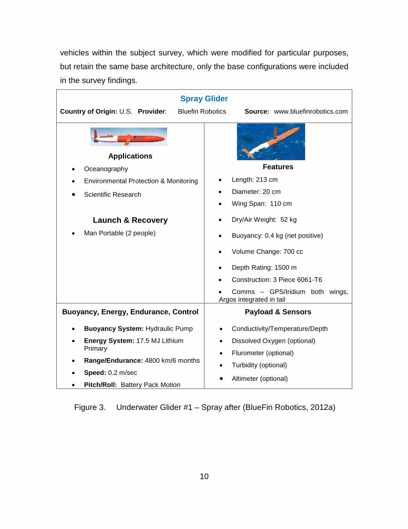
Spray Glider Country of Origin: U.S. Provider: Bluefin Robotics Source: www.bluefinrobotics.com
Applications • Oceanography
• Environmental Protection & Monitoring
• Scientific Research
Launch & Recovery • Man Portable (2 people)
Features • Length: 213 cm
• Diameter: 20 cm
• Wing Span: 110 cm
• Dry/Air Weight: 52 kg
• Buoyancy: 0.4 kg (net positive)
• Volume Change: 700 cc
• Depth Rating: 1500 m
• Construction: 3 Piece 6061-T6
• Comms – GPS/Iridium both wings, Argos integrated in tail
Buoyancy, Energy, Endurance, Control
• Buoyancy System: Hydraulic Pump
• Energy System: 17.5 MJ Lithium Primary
• Range/Endurance: 4800 km/6 months
• Speed: 0.2 m/sec
• Pitch/Roll: Battery Pack Motion
Payload & Sensors
• Conductivity/Temperature/Depth
• Dissolved Oxygen (optional)
• Flurometer (optional)
• Turbidity (optional)
• Altimeter (optional)
Figure 3. Underwater Glider #1 – Spray after (BlueFin Robotics, 2012a)
11
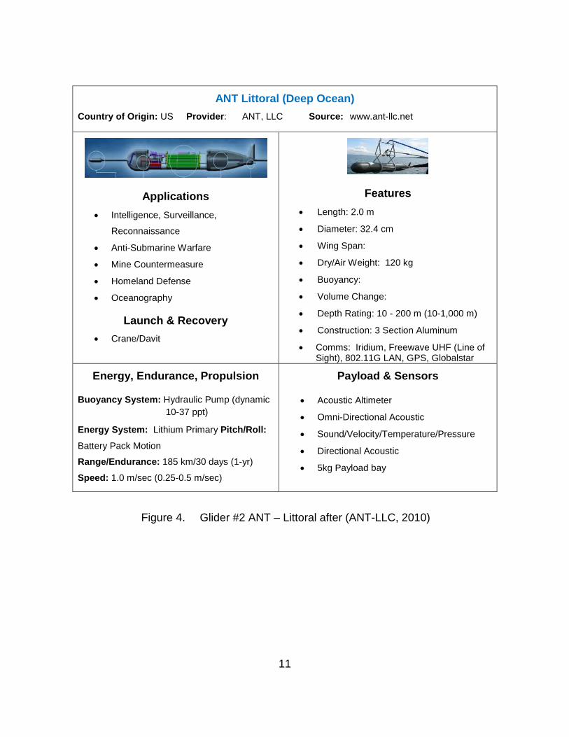
ANT Littoral (Deep Ocean) Country of Origin: US Provider: ANT, LLC Source: www.ant-llc.net
Applications • Intelligence, Surveillance,
Reconnaissance
• Anti-Submarine Warfare
• Mine Countermeasure
• Homeland Defense
• Oceanography
Launch & Recovery • Crane/Davit
Features • Length: 2.0 m
• Diameter: 32.4 cm
• Wing Span:
• Dry/Air Weight: 120 kg
• Buoyancy:
• Volume Change:
• Depth Rating: 10 - 200 m (10-1,000 m)
• Construction: 3 Section Aluminum
• Comms: Iridium, Freewave UHF (Line of Sight), 802.11G LAN, GPS, Globalstar
Energy, Endurance, Propulsion
Buoyancy System: Hydraulic Pump (dynamic 10-37 ppt)
Energy System: Lithium Primary Pitch/Roll:
Battery Pack Motion Range/Endurance: 185 km/30 days (1-yr)
Speed: 1.0 m/sec (0.25-0.5 m/sec)
Payload & Sensors
• Acoustic Altimeter
• Omni-Directional Acoustic
• Sound/Velocity/Temperature/Pressure
• Directional Acoustic
• 5kg Payload bay
Figure 4. Glider #2 ANT – Littoral after (ANT-LLC, 2010)
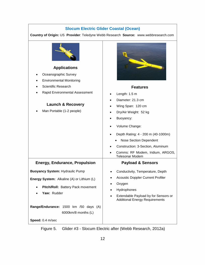
12
Slocum Electric Glider Coastal (Ocean) Country of Origin: US Provider: Teledyne Webb Research Source: www.webbresearch.com
Applications • Oceanographic Survey
• Environmental Monitoring
• Scientific Research
• Rapid Environmental Assessment
Launch & Recovery • Man Portable (1-2 people)
Features • Length: 1.5 m
• Diameter: 21.3 cm
• Wing Span: 120 cm
• Dry/Air Weight: 52 kg
• Buoyancy:
• Volume Change:
• Depth Rating: 4 - 200 m (40-1000m)
• Nose Section Dependent
• Construction: 3-Section, Aluminum
• Comms: RF Modem, Iridium, ARGOS, Telesonar Modem
Energy, Endurance, Propulsion
Buoyancy System: Hydraulic Pump
Energy System: Alkaline (A) or Lithium (L)
• Pitch/Roll: Battery Pack movement
• Yaw: Rudder
Range/Endurance: 1500 km /50 days (A)
6000km/8 months (L)
Speed: 0.4 m/sec
Payload & Sensors
• Conductivity, Temperature, Depth
• Acoustic Doppler Current Profiler
• Oxygen
• Hydrophones
• Extendable Payload by for Sensors or Additional Energy Requirements
Figure 5. Glider #3 - Slocum Electric after (Webb Research, 2012a)

13
Slocum Thermal Glider Country of Origin: US Provider: Teledyne Webb Research Source: www.webbresearch.com
Applications • Oceanographic Survey
• Environmental Monitoring
• Scientific Research
Launch & Recovery • Man Portable (1-2 people)
Features • Length: 1.5 m
• Diameter: 21.3 cm (main body)
• Wing Span: 120 cm
• Dry/Air Weight: 60 kg
• Buoyancy:
• Volume Change:
• Depth Rating: 1200 m
• Construction: 3-Section, Aluminum
• Comms: RF Modem, Iridium, ARGOS,
Energy, Endurance, Propulsion
Buoyancy System: Thermal Pump
Energy System: Environmental
• Pitch/Roll: Battery Pack movement
• Yaw: Rudder
Range/Endurance: 40,000 km/3-5 years
Speed: 0.4 m/sec
Payload & Sensors
• Conductivity, Temperature, Depth
Figure 6. Glider #4 -Slocum Thermal after (Webb Research, 2012b)
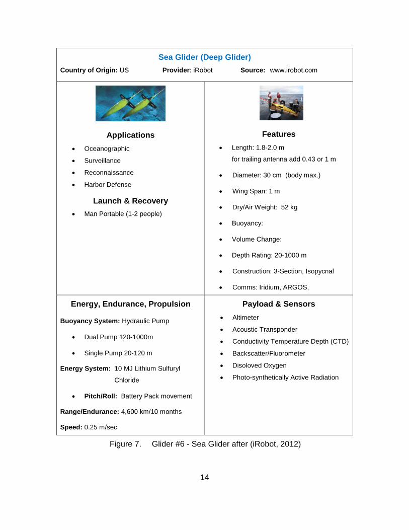
14
Sea Glider (Deep Glider) Country of Origin: US Provider: iRobot Source: www.irobot.com
Applications • Oceanographic
• Surveillance
• Reconnaissance
• Harbor Defense
Launch & Recovery • Man Portable (1-2 people)
Features • Length: 1.8-2.0 m
for trailing antenna add 0.43 or 1 m
• Diameter: 30 cm (body max.)
• Wing Span: 1 m
• Dry/Air Weight: 52 kg
• Buoyancy:
• Volume Change:
• Depth Rating: 20-1000 m
• Construction: 3-Section, Isopycnal
• Comms: Iridium, ARGOS,
Energy, Endurance, Propulsion
Buoyancy System: Hydraulic Pump
• Dual Pump 120-1000m
• Single Pump 20-120 m
Energy System: 10 MJ Lithium Sulfuryl
Chloride
• Pitch/Roll: Battery Pack movement
Range/Endurance: 4,600 km/10 months
Speed: 0.25 m/sec
Payload & Sensors • Altimeter
• Acoustic Transponder
• Conductivity Temperature Depth (CTD)
• Backscatter/Fluorometer
• Disoloved Oxygen
• Photo-synthetically Active Radiation
Figure 7. Glider #6 - Sea Glider after (iRobot, 2012)
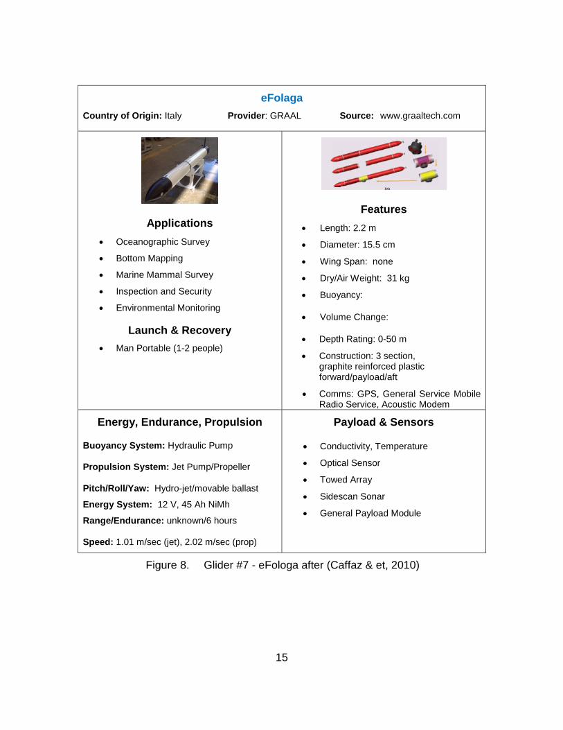
15
eFolaga Country of Origin: Italy Provider: GRAAL Source: www.graaltech.com
Applications • Oceanographic Survey
• Bottom Mapping
• Marine Mammal Survey
• Inspection and Security
• Environmental Monitoring
Launch & Recovery • Man Portable (1-2 people)
Features • Length: 2.2 m
• Diameter: 15.5 cm
• Wing Span: none
• Dry/Air Weight: 31 kg
• Buoyancy:
• Volume Change:
• Depth Rating: 0-50 m
• Construction: 3 section, graphite reinforced plastic forward/payload/aft
• Comms: GPS, General Service Mobile Radio Service, Acoustic Modem
Energy, Endurance, Propulsion
Buoyancy System: Hydraulic Pump
Propulsion System: Jet Pump/Propeller
Pitch/Roll/Yaw: Hydro-jet/movable ballast
Energy System: 12 V, 45 Ah NiMh
Range/Endurance: unknown/6 hours
Speed: 1.01 m/sec (jet), 2.02 m/sec (prop)
Payload & Sensors
• Conductivity, Temperature
• Optical Sensor
• Towed Array
• Sidescan Sonar
• General Payload Module
Figure 8. Glider #7 - eFologa after (Caffaz & et, 2010)
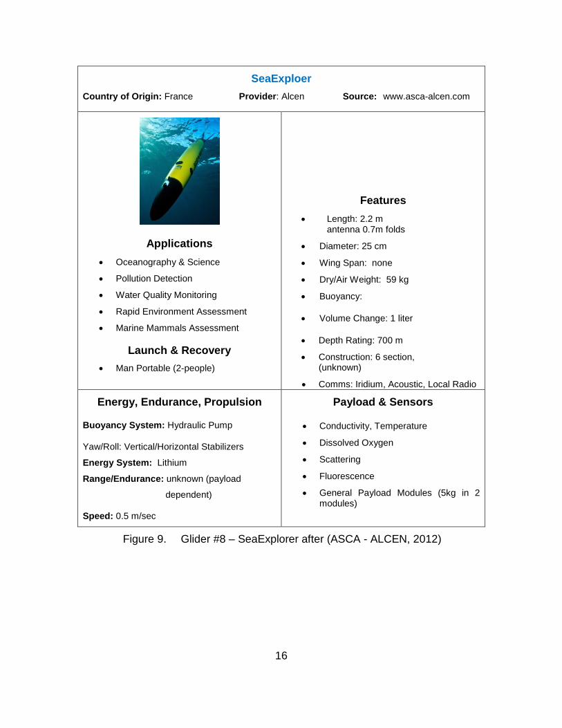
16
SeaExploer Country of Origin: France Provider: Alcen Source: www.asca-alcen.com
Applications • Oceanography & Science
• Pollution Detection
• Water Quality Monitoring
• Rapid Environment Assessment
• Marine Mammals Assessment
Launch & Recovery • Man Portable (2-people)
Features • Length: 2.2 m
antenna 0.7m folds
• Diameter: 25 cm
• Wing Span: none
• Dry/Air Weight: 59 kg
• Buoyancy:
• Volume Change: 1 liter
• Depth Rating: 700 m
• Construction: 6 section, (unknown)
• Comms: Iridium, Acoustic, Local Radio
Energy, Endurance, Propulsion
Buoyancy System: Hydraulic Pump
Yaw/Roll: Vertical/Horizontal Stabilizers
Energy System: Lithium
Range/Endurance: unknown (payload
dependent)
Speed: 0.5 m/sec
Payload & Sensors
• Conductivity, Temperature
• Dissolved Oxygen
• Scattering
• Fluorescence
• General Payload Modules (5kg in 2 modules)
Figure 9. Glider #8 – SeaExplorer after (ASCA - ALCEN, 2012)
17
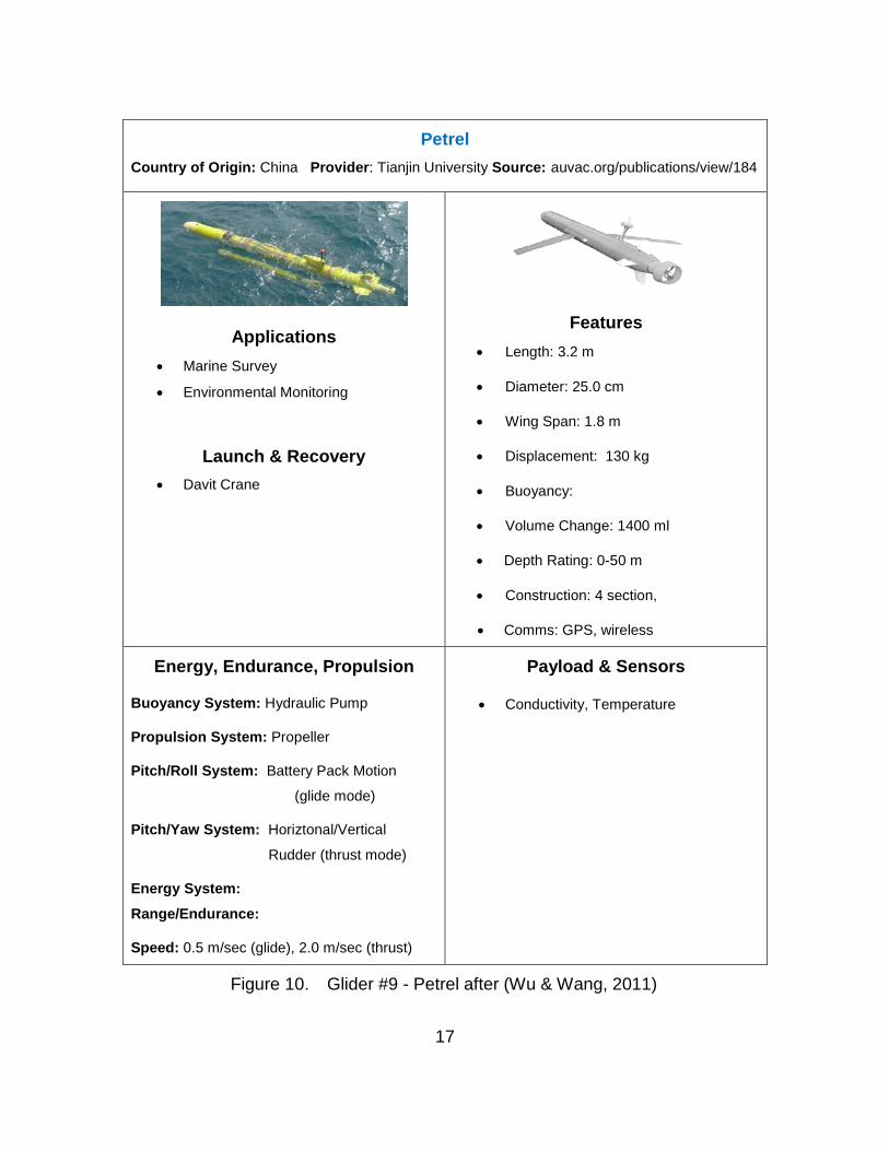
Petrel Country of Origin: China Provider: Tianjin University Source: auvac.org/publications/view/184
Applications • Marine Survey
• Environmental Monitoring
Launch & Recovery
• Davit Crane
Features • Length: 3.2 m
• Diameter: 25.0 cm
• Wing Span: 1.8 m
• Displacement: 130 kg
• Buoyancy:
• Volume Change: 1400 ml
• Depth Rating: 0-50 m
• Construction: 4 section,
• Comms: GPS, wireless
Energy, Endurance, Propulsion
Buoyancy System: Hydraulic Pump
Propulsion System: Propeller
Pitch/Roll System: Battery Pack Motion
(glide mode)
Pitch/Yaw System: Horiztonal/Vertical
Rudder (thrust mode)
Energy System:
Range/Endurance:
Speed: 0.5 m/sec (glide), 2.0 m/sec (thrust)
Payload & Sensors
• Conductivity, Temperature
Figure 10. Glider #9 - Petrel after (Wu & Wang, 2011)
18
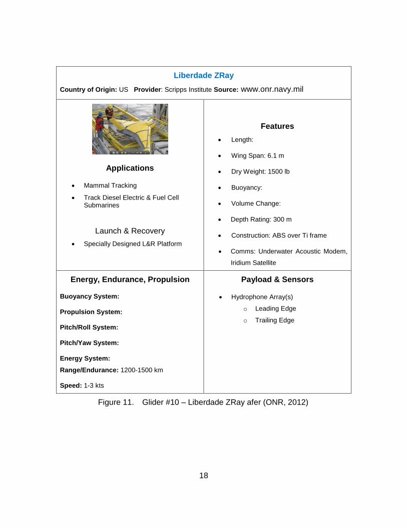
Liberdade ZRay Country of Origin: US Provider: Scripps Institute Source: www.onr.navy.mil
Applications
• Mammal Tracking
• Track Diesel Electric & Fuel Cell Submarines
Launch & Recovery
• Specially Designed L&R Platform
Features • Length:
• Wing Span: 6.1 m
• Dry Weight: 1500 lb
• Buoyancy:
• Volume Change:
• Depth Rating: 300 m
• Construction: ABS over Ti frame
• Comms: Underwater Acoustic Modem,
Iridium Satellite
Energy, Endurance, Propulsion
Buoyancy System:
Propulsion System:
Pitch/Roll System:
Pitch/Yaw System:
Energy System:
Range/Endurance: 1200-1500 km
Speed: 1-3 kts
Payload & Sensors
• Hydrophone Array(s)
o Leading Edge
o Trailing Edge
Figure 11. Glider #10 – Liberdade ZRay afer (ONR, 2012)
19
Additionally, as stealth is of major importance for tactical underwater
gliders, those vehicles with portions, which normally reside on the ocean surface
were not considered. (An example of this is the WaveGlider, from Liquid
Robotics (Liquid Robotics, 2012), which utilizes wave motion to provide the
forward/downward and upward cyclic motion for its submerged vehicle which is in
turn tethered to a surf-board like vehicle on the ocean surface.)
Furthermore, complete data was not available, or proprietary, for all of the
gliders contained in the survey. Accordingly, the quad charts may exhibit blank
data fields where information was unavailable from open sources.
C. CHAPTER SUMMARY
This chapter presented a survey of the available underwater gliders from
within the U.S. and abroad. Both proper buoyancy driven and hybrid
buoyancy/propulsive gliders were considered in this survey. Those gliders used
by academia, commercial and military prototypes were not considered as they
have not reached even low initial rate of production (LRIP) quantities. There
exists a limited number of underwater gliders with complete characterization
information available in open literature. Therefore, only those gliders with
complete characterization information available were carried into the study on
underwater glider system architectural features relevant to a U.S. Navy
underwater glider discussed in the following chapter.

20
THIS PAGE INTENTIONALLY LEFT BLANK
21
III. SELECTION OF GLIDER SYSTEMS, SIGNIFICANT GLIDER ARCHITECTURE ATTRIBUTES AND SYSTEM CONSIDERATIONS
THAT INFLUENCE THESE ATTRIBUTES
A. INTRODUCTION
This chapter down selects from the underwater gliders surveyed in the
previous chapter in order to provide a comparison of the associated significant
architectural attributes. Although the underwater glider survey resulted in a
compilation of conventional (buoyancy only), hybrid gliders (buoyancy and
propulsion) and flying wing gliders only conventional and hybrid gliders are
considered in the following architectural attribute discussion. This is necessary
to restrain the scope of the resultant architectural attribute discussion.
Additionally, the conventional and hybrid gliders selected have significantly more
at-sea time and higher current or near-term rates of production than the flying
wing glider (Liberdade Zray). Note, one hybrid glider, Petrel, had insufficient open
source information available regarding internal arrangement of components or its
operation. Therefore, this glider was eliminated from the study that follows and
should be reconsidered once more open source information becomes available.
B. GLIDER SYSTEM SELECTION
For this effort, seven underwater gliders were deemed either commercial
successes or had significant potential for near term viable commercial
successes. The determination of current commercial or near term viable
commercial success was based on four traits: number of units sold, number of
similar prototypes successfully at-sea tested or demonstrated,
manufacturer/distributor training availability and at-sea time. The section, which
follows, delineates the basic information of each glider and consists of
identification of the manufacturer, key features of the glider and external and
cross-sectional view of the associated glider. The gliders are presented in the
following order:
22
• Spray
• ANT
• Slocum Electric
• Slocum Thermal
• Sea Glider
• eFolaga
• SeaExplorer
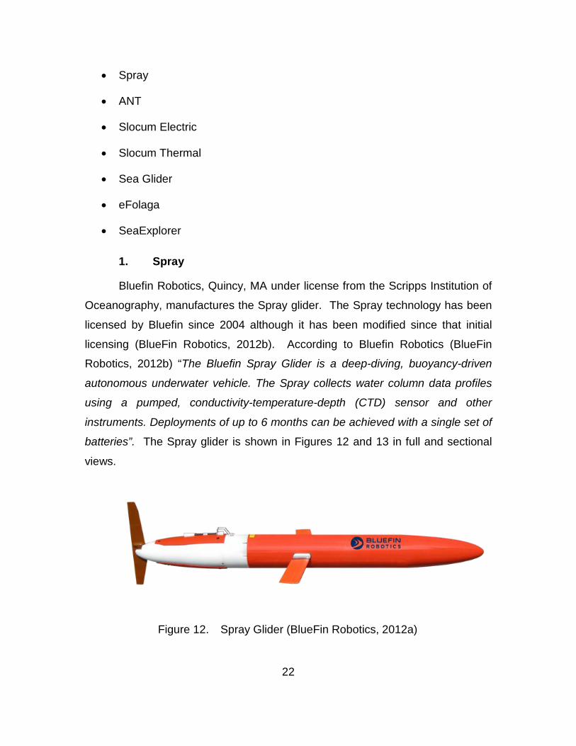
1. Spray
Bluefin Robotics, Quincy, MA under license from the Scripps Institution of
Oceanography, manufactures the Spray glider. The Spray technology has been
licensed by Bluefin since 2004 although it has been modified since that initial
licensing (BlueFin Robotics, 2012b). According to Bluefin Robotics (BlueFin
Robotics, 2012b) “The Bluefin Spray Glider is a deep-diving, buoyancy-driven
autonomous underwater vehicle. The Spray collects water column data profiles
using a pumped, conductivity-temperature-depth (CTD) sensor and other
instruments. Deployments of up to 6 months can be achieved with a single set of
batteries”. The Spray glider is shown in Figures 12 and 13 in full and sectional
views.
Figure 12. Spray Glider (BlueFin Robotics, 2012a)
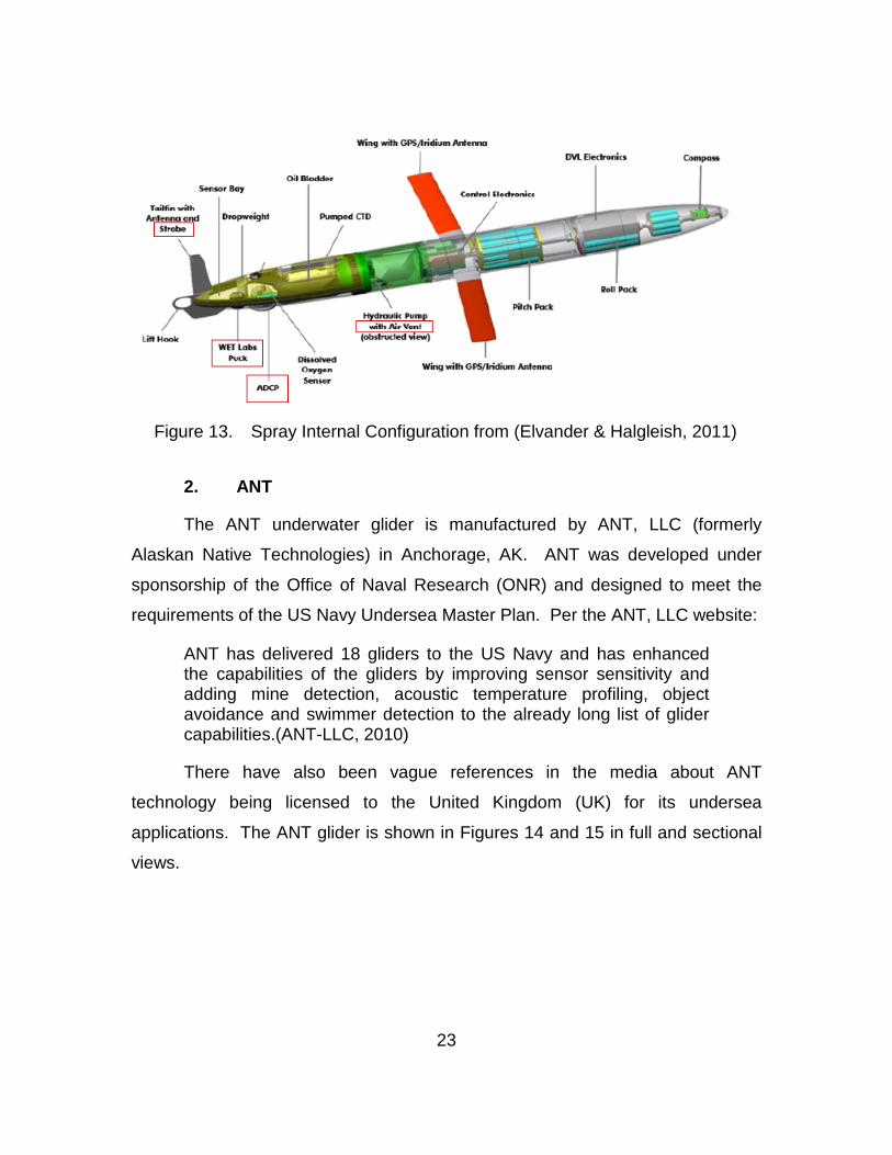
23
Figure 13. Spray Internal Configuration from (Elvander & Halgleish, 2011)
2. ANT
The ANT underwater glider is manufactured by ANT, LLC (formerly
Alaskan Native Technologies) in Anchorage, AK. ANT was developed under
sponsorship of the Office of Naval Research (ONR) and designed to meet the
requirements of the US Navy Undersea Master Plan. Per the ANT, LLC website:
ANT has delivered 18 gliders to the US Navy and has enhanced the capabilities of the gliders by improving sensor sensitivity and adding mine detection, acoustic temperature profiling, object avoidance and swimmer detection to the already long list of glider capabilities.(ANT-LLC, 2010)
There have also been vague references in the media about ANT
technology being licensed to the United Kingdom (UK) for its undersea
applications. The ANT glider is shown in Figures 14 and 15 in full and sectional
views.
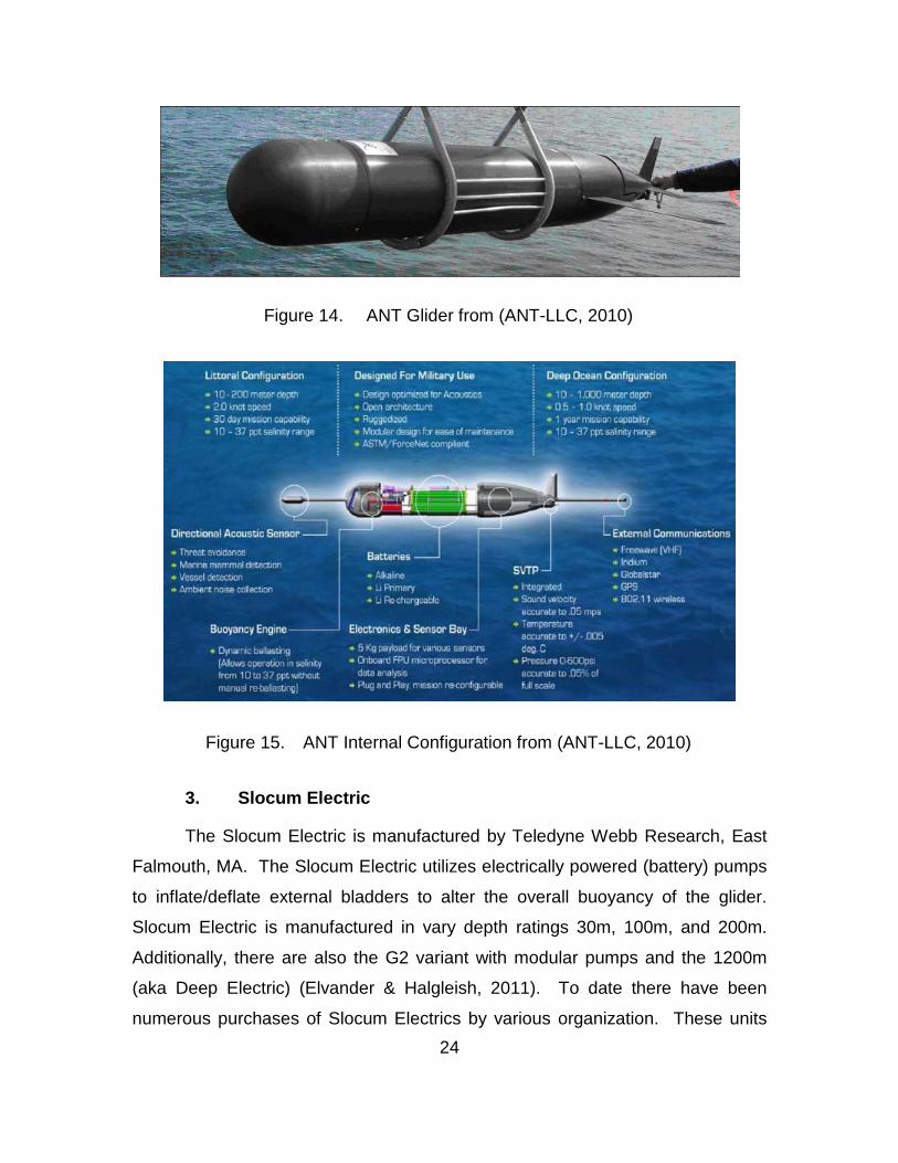
24
Figure 14. ANT Glider from (ANT-LLC, 2010)
Figure 15. ANT Internal Configuration from (ANT-LLC, 2010)
3. Slocum Electric
The Slocum Electric is manufactured by Teledyne Webb Research, East
Falmouth, MA. The Slocum Electric utilizes electrically powered (battery) pumps
to inflate/deflate external bladders to alter the overall buoyancy of the glider.
Slocum Electric is manufactured in vary depth ratings 30m, 100m, and 200m.
Additionally, there are also the G2 variant with modular pumps and the 1200m
(aka Deep Electric) (Elvander & Halgleish, 2011). To date there have been
numerous purchases of Slocum Electrics by various organization. These units
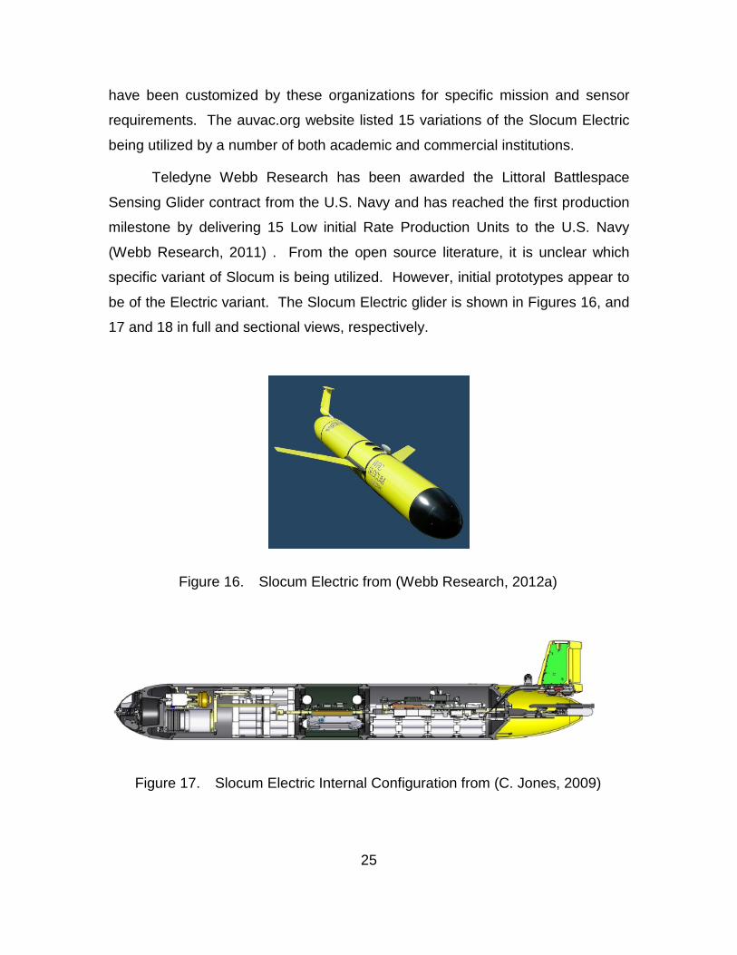
25
have been customized by these organizations for specific mission and sensor
requirements. The auvac.org website listed 15 variations of the Slocum Electric
being utilized by a number of both academic and commercial institutions.
Teledyne Webb Research has been awarded the Littoral Battlespace
Sensing Glider contract from the U.S. Navy and has reached the first production
milestone by delivering 15 Low initial Rate Production Units to the U.S. Navy
(Webb Research, 2011) . From the open source literature, it is unclear which
specific variant of Slocum is being utilized. However, initial prototypes appear to
be of the Electric variant. The Slocum Electric glider is shown in Figures 16, and
17 and 18 in full and sectional views, respectively.
Figure 16. Slocum Electric from (Webb Research, 2012a)
Figure 17. Slocum Electric Internal Configuration from (C. Jones, 2009)
26
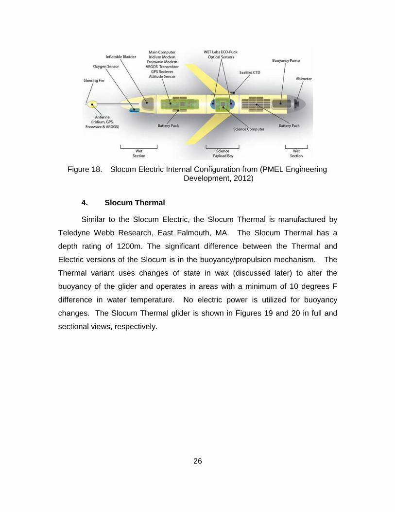
Figure 18. Slocum Electric Internal Configuration from (PMEL Engineering
Development, 2012)
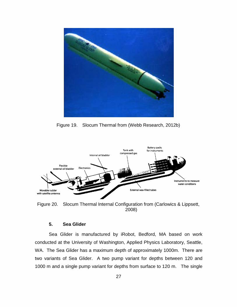
4. Slocum Thermal
Similar to the Slocum Electric, the Slocum Thermal is manufactured by
Teledyne Webb Research, East Falmouth, MA. The Slocum Thermal has a
depth rating of 1200m. The significant difference between the Thermal and
Electric versions of the Slocum is in the buoyancy/propulsion mechanism. The
Thermal variant uses changes of state in wax (discussed later) to alter the
buoyancy of the glider and operates in areas with a minimum of 10 degrees F
difference in water temperature. No electric power is utilized for buoyancy
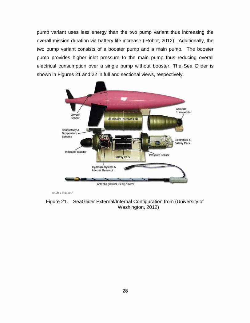
changes. The Slocum Thermal glider is shown in Figures 19 and 20 in full and
sectional views, respectively.
27
Figure 19. Slocum Thermal from (Webb Research, 2012b)
Figure 20. Slocum Thermal Internal Configuration from (Carlowics & Lippsett,
2008)
5. Sea Glider
Sea Glider is manufactured by iRobot, Bedford, MA based on work
conducted at the University of Washington, Applied Physics Laboratory, Seattle,
WA. The Sea Glider has a maximum depth of approximately 1000m. There are
two variants of Sea Glider. A two pump variant for depths between 120 and
1000 m and a single pump variant for depths from surface to 120 m. The single
28
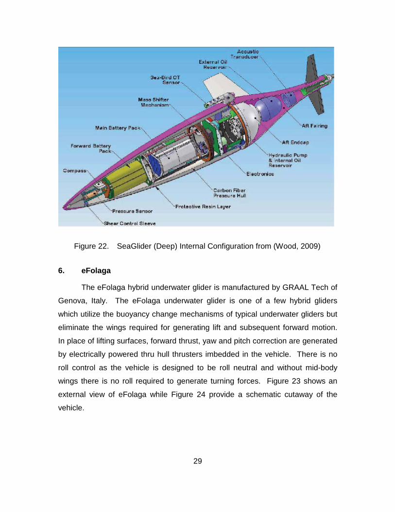
pump variant uses less energy than the two pump variant thus increasing the
overall mission duration via battery life increase (iRobot, 2012). Additionally, the
two pump variant consists of a booster pump and a main pump. The booster
pump provides higher inlet pressure to the main pump thus reducing overall
electrical consumption over a single pump without booster. The Sea Glider is
shown in Figures 21 and 22 in full and sectional views, respectively.
Figure 21. SeaGlider External/Internal Configuration from (University of
Washington, 2012)
29
Figure 22. SeaGlider (Deep) Internal Configuration from (Wood, 2009)
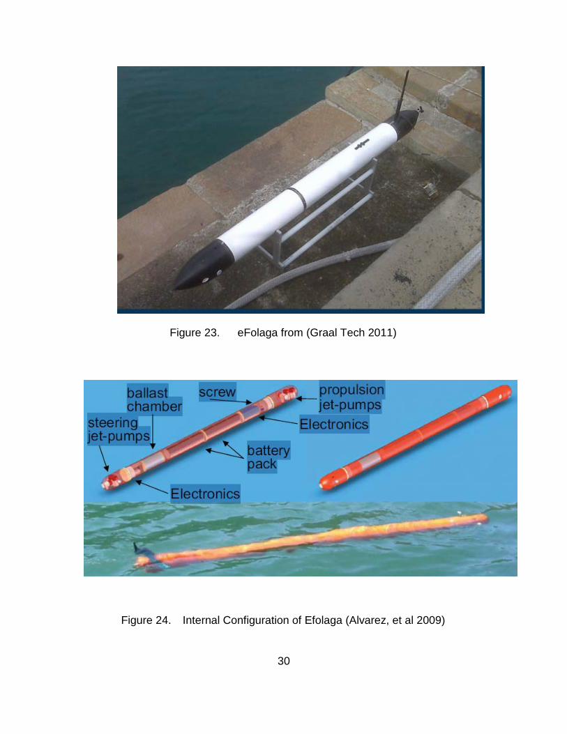
6. eFolaga
The eFolaga hybrid underwater glider is manufactured by GRAAL Tech of
Genova, Italy. The eFolaga underwater glider is one of a few hybrid gliders
which utilize the buoyancy change mechanisms of typical underwater gliders but
eliminate the wings required for generating lift and subsequent forward motion.
In place of lifting surfaces, forward thrust, yaw and pitch correction are generated
by electrically powered thru hull thrusters imbedded in the vehicle. There is no
roll control as the vehicle is designed to be roll neutral and without mid-body
wings there is no roll required to generate turning forces. Figure 23 shows an
external view of eFolaga while Figure 24 provide a schematic cutaway of the
vehicle.
30
Figure 23. eFolaga from (Graal Tech 2011)
Figure 24. Internal Configuration of Efolaga (Alvarez, et al 2009)
31
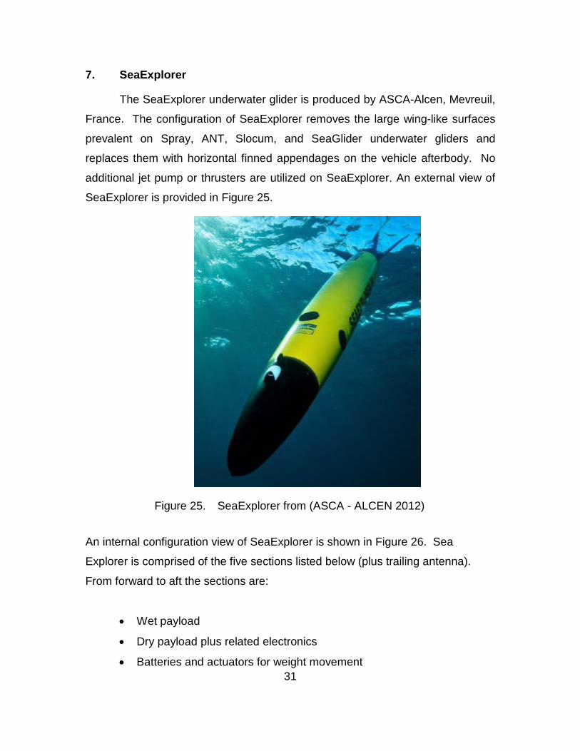
7. SeaExplorer
The SeaExplorer underwater glider is produced by ASCA-Alcen, Mevreuil,
France. The configuration of SeaExplorer removes the large wing-like surfaces
prevalent on Spray, ANT, Slocum, and SeaGlider underwater gliders and
replaces them with horizontal finned appendages on the vehicle afterbody. No
additional jet pump or thrusters are utilized on SeaExplorer. An external view of
SeaExplorer is provided in Figure 25.
Figure 25. SeaExplorer from (ASCA - ALCEN 2012)
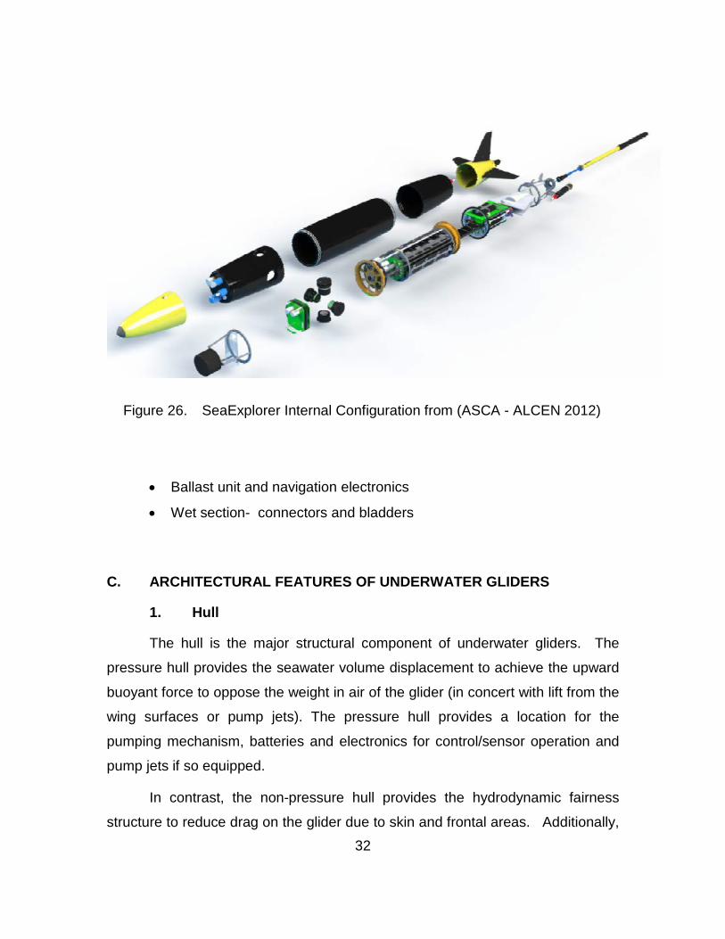
An internal configuration view of SeaExplorer is shown in Figure 26. Sea
Explorer is comprised of the five sections listed below (plus trailing antenna).
From forward to aft the sections are:
• Wet payload
• Dry payload plus related electronics
• Batteries and actuators for weight movement
32
Figure 26. SeaExplorer Internal Configuration from (ASCA - ALCEN 2012)
• Ballast unit and navigation electronics
• Wet section- connectors and bladders
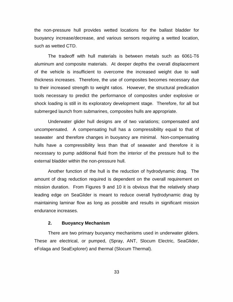
C. ARCHITECTURAL FEATURES OF UNDERWATER GLIDERS
1. Hull
The hull is the major structural component of underwater gliders. The
pressure hull provides the seawater volume displacement to achieve the upward
buoyant force to oppose the weight in air of the glider (in concert with lift from the
wing surfaces or pump jets). The pressure hull provides a location for the
pumping mechanism, batteries and electronics for control/sensor operation and
pump jets if so equipped.
In contrast, the non-pressure hull provides the hydrodynamic fairness
structure to reduce drag on the glider due to skin and frontal areas. Additionally,
33
the non-pressure hull provides wetted locations for the ballast bladder for
buoyancy increase/decrease, and various sensors requiring a wetted location,
such as wetted CTD.
The tradeoff with hull materials is between metals such as 6061-T6
aluminum and composite materials. At deeper depths the overall displacement
of the vehicle is insufficient to overcome the increased weight due to wall
thickness increases. Therefore, the use of composites becomes necessary due
to their increased strength to weight ratios. However, the structural predication
tools necessary to predict the performance of composites under explosive or
shock loading is still in its exploratory development stage. Therefore, for all but
submerged launch from submarines, composites hulls are appropriate.
Underwater glider hull designs are of two variations; compensated and
uncompensated. A compensating hull has a compressibility equal to that of
seawater and therefore changes in buoyancy are minimal. Non-compensating
hulls have a compressibility less than that of seawater and therefore it is
necessary to pump additional fluid from the interior of the pressure hull to the
external bladder within the non-pressure hull.
Another function of the hull is the reduction of hydrodynamic drag. The
amount of drag reduction required is dependent on the overall requirement on
mission duration. From Figures 9 and 10 it is obvious that the relatively sharp
leading edge on SeaGlider is meant to reduce overall hydrodynamic drag by
maintaining laminar flow as long as possible and results in significant mission
endurance increases.
2. Buoyancy Mechanism
There are two primary buoyancy mechanisms used in underwater gliders.
These are electrical, or pumped, (Spray, ANT, Slocum Electric, SeaGlider,
eFolaga and SeaExplorer) and thermal (Slocum Thermal).
34
The electrical (pumped) variant works by use of a bladder external to the
pressure hull but within the fairing which is either filled with or purged of fluid
(water or oil) taken from inside the pressure hull. Filling the bladder with fluid
increases the buoyancy of the glider resulting in an upward motion. The upward
motion is translated to a forward motion due to the lifting forces caused by flow
over the wing surfaces. (Alternately, for gliders without wings, for example
eFolaga, jet pump thrusters initiate the forward motion). Similarly a downward
motion is initiated by pumping fluid out of the bladder thus reducing the gliders
overall buoyancy.
The thermal variant works via a state change of a wax-like substance. As
described on the AUVAC website:
The thermal engine consists of a heat exchange tube, accumulator, valve manifold, and both external and internal (to the pressure hull) bladders. The heat exchange tube is comprised of an outer aluminum pressure vessel that is filled with a wax chemistry tuned to undergo a phase change at 10 C. In the center of the wax is a flexible hose which can be filled with mineral oil. In operation, the glider leaves the surface by rotating the valve and allowing oil from an external bladder to enter into the pressure hull to an internal bladder, decreasing vehicle volume, causing the vehicle to descend. (AUVAC, 2012)
The most significant shortfall with the thermal glider is the necessity for a 10 C
temperature difference for operation. This limits the use of thermal gliders to
approximately 65 percent of the world’s oceans (C. Jones, Allsup, & Altshuler,
2010). Additionally, to speed heat transfer, the heat exchange tubes are
normally placed external to the vehicle. (See Figure 19 for reference.) Placing
the heat exchanger tubes external to the non-pressure hull or fairing adds an
additional encumbrance with regard to debris accumulation and has a
detrimental effect on vehicle drag. The above however, neglects the significant
energy savings from the use of the readily available thermal cycle. There is no
energy cost (pump operation) for the cyclic motion of the glider thus the available
battery energy is utilized to operate the pitch/roll controls and sensors. This
35
energy savings results in a substantial increase in flight duration relative to an
electric glider for the same battery configuration (number & type).
The main drawback of the thermal glider is its limited efficiency.
The thermal cycle has a very low efficiency, approximately 3%, due to the small temperature differences. The low efficiency itself is not a handicap since there are large sources and sinks of heat, however, the low efficiency means a large heat flow relative to the useful work that is done. Therefore, the glide path of a thermal glider is almost double that of the electric gliders. This is necessary to constantly harvest the oceans energy for glider usage. (Webb, Simonetti, & Jones, 2001b)
3. Wings and Stabilizer Surfaces
The wings, or airfoil shapes, utilized on conventional underwater gliders (Spray,
ANT, Slocum Electric and Thermal, SeaGlider) are symmetrical for gliding
upward and downward and are thin flat wings with sharp leading edges (Webb,
Simonetti, & Jones, 2001a). The wings are positioned at an angle of
approximately 45 degrees to the main longitudinal axis (fore/aft) of the glider.
The wing span and foil shape vary dependent on the overall dry weight of
the glider, buoyancy of the glider and the desired ‘forward’ speed characteristics.
The relatively sharp angle of the wings prevents debris accumulation on the
lifting surfaces. The wings on some production models (SLOCUM Electric or
LBS) are also removable for shipping and stowage and are installed only during
pre-launch preparations. The glider Spray also uses the wings to house the
antenna for the iridium satellite up/down link function.
Two exceptions to the use of relatively large wings to generate lift are the
eFolaga (no wings, smooth body) and the SeaGlider (no wings, but aft lifting
surfaces in place of wings). eFolaga uses a jet pump aft to generate thrust and
induce forward motion of the vehicle in place of the buoyancy force coupled with
the lift generated by the flow over fixed wings. The lack of wings reduces the
possibility of any debris accumulation on the eFolaga vehicle. (Also of note for
eFolaga is that the vehicle mission duration is limited to 6 hours at maximum
36
speed. This pales in comparison to the durations of Spray, ANT, Slocum and
SeaGlider. This indicates that although providing more vehicle maneuverability
in the short-term, long-term mission duration is significantly impaired.)
The gliders also have either a single fixed vertical stabilizer (Spray,
SeaGlider), controllable vertical rudder (Slocum Electric and Thermal) or vertical
and horizontal stabilizer at the afterbody (ANT, SeaExplorer). These serve to
both stabilize flight and to control the turning of the glider to follow the ascribed
flight path as described in the section which follows.
4. Control (pitch, yaw, roll)
For all subject vehicles, pitch is primarily controlled by movement of liquid
(oil/water) from internal to external reservoirs relative to the pressure hull. Fine-
tuning of pitch is accomplished by minimized longitudinal motion of battery
pack(s) within the vehicle pressure hull. Longitudinal motion of the battery
pack(s) effectively changes/reverses the separation distance between center of
gravity and center of buoyancy. This allows battery packs to serve dual
functions: energy for sensors, pumps, valves and ballast (as required).
For the Slocum gliders, a vertical rudder at the aft portion of the vehicle is
operated by the onboard vehicle control system to provide the desired turning
rate characteristics. This eliminates roll from vehicle motion allowing the
altimeter to function correctly without waiting for the vehicle to stabilize. Other
vehicles, such as Spray, incorporate a separate, rotational, battery pack to
induce roll and thus turning. This is described further below:
This gives the lift vector a horizontal component and induces vehicle sideslip in the plane of the wing in the direction of the buoyant force. The horizontal component of lift provides the centripetal force for turning while sideslip acting on the vertical stabilizer produces the yaw moment needed to change vehicle heading. For example, to turn right during descent the right wing is dropped, like a conventional airplane, generating a lift component to the right that drives to the vehicle to the right. Sideslips down and to the right acts on the vertical stabilizer causing the nose to
37
yaw to the right. To turn right in ascent the glider is rolled oppositely by dropping the left wing. (Davis, Eriksen, & Jones, 2002)
Additionally, the aft position of the wings relative to the glider nose
determines its turning mechanism. For instance, Sea Glider’s wings are
considerably more aft than Spray’s resulting in opposite turn characteristics.
The wing is so far aft that the turning dynamics are opposite that of Spray. In descent, to turn right the vehicle’s left wing is dropped so that lift on the wing drives the stern to the left, overcoming lift off the vertical stabilizer, and initiating a turn to the right. Hydrodynamic lift on the sideslipping hull produces the centripetal force to curve the course. Conversely, in ascent a roll to the left produces a turn to the left. (Davis, Eriksen, & Jones, 2002)
For eFolaga there is no roll control as the vehicle was designed as roll
neutral and thus there is no roll mechanism for turning within the vehicle. Instead
pitch and yaw adjustments are accomplished via the use of thru hull jet thrusters
to provide yaw and pitch control. This allows relatively horizontal attitude of the
vehicle for all maneuvers which may be useful for certain sensor packages (i.e.
bottom imaging or side scan sonars).
5. Sensors Wetted and Non-wetted
A number of sensors are either standard equipment or available as
options on underwater gliders, see Figures 3 thru 7. The standard equipment
usually includes a Conductivity, Temperature, Depth (CTD) sensor, compass and
altitude. Any additional sensors are incorporated into a payload bay or within the
existing wet space forward or aft of the pressure hull and under the fairings.
Dependent on the sensor utilized the energy consumption may increase and
result in reduced mission duration times. To overcome this issue glider makers
such as Webb Research (Slocum) offer an extended battery variant. For
sensors, the trade-off is between sensor need/data value, energy consumption
and mission duration requirements. Additionally, the glider must be capable of
providing the control necessary for the given sensor. For instance, side scan
sonar has severe requirements on allowable vehicle roll, therefore a comparison
38
of the sensor specifications versus vehicle capabilities is mandatory before
considering the installation of any sensor on the vehicle. Additionally, the effects
of changes in vehicle center of gravity and center of buoyancy on flight
characteristics must be understood.
6. Communication/Navigation
Communications/navigation fixes from the underwater glider to the remote
underwater glider control station (or stations) are conducted during vehicle
surfacing and subsequent exposure of the Iridium satellite or GPS antenna.
Exposure of the antenna is initiated by increasing aft buoyancy for trailing and
built-in (rudder) antenna variants (Sea Glider, ANT and Slocum, eFolaga,
SeaExplorer, respectively). This results in a significant down-angle of the vehicle
relative to the vehicle’s nose.
Uniquely, Spray utilizes an antenna which is built into its wing and uses
the rotary battery ballast to roll the vehicle (and corresponding wing)
approximately 30 degrees out of the water.
With the antenna exposed communication with the control station occurs
with data being uplinked and new mission profiles being downlinked. The glider
then submerges and begins its new mission with the corresponding updated
mission profiles.
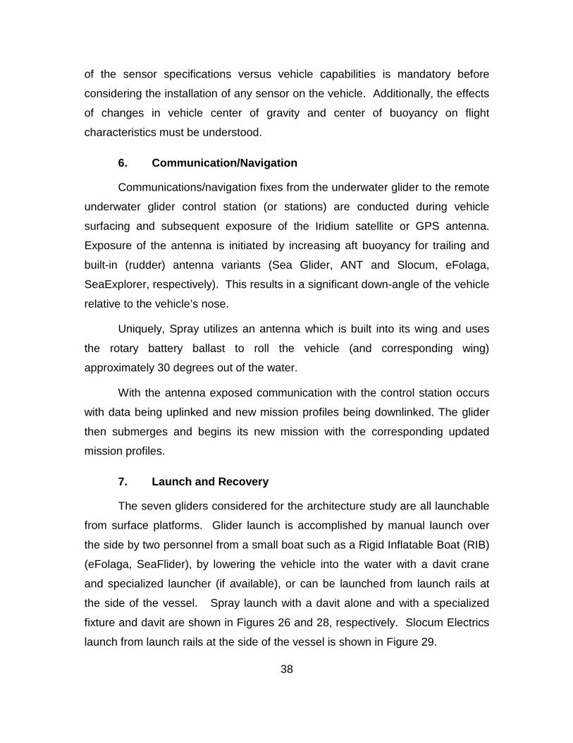
7. Launch and Recovery
The seven gliders considered for the architecture study are all launchable
from surface platforms. Glider launch is accomplished by manual launch over
the side by two personnel from a small boat such as a Rigid Inflatable Boat (RIB)
(eFolaga, SeaFlider), by lowering the vehicle into the water with a davit crane
and specialized launcher (if available), or can be launched from launch rails at
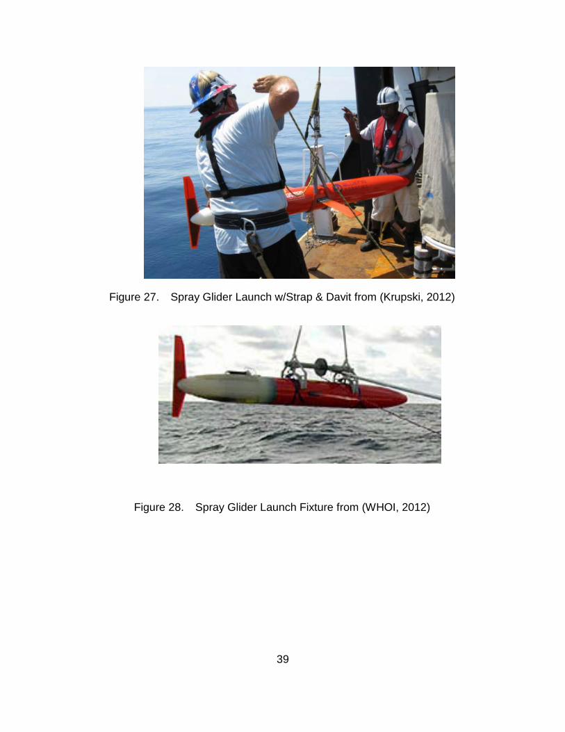
the side of the vessel. Spray launch with a davit alone and with a specialized
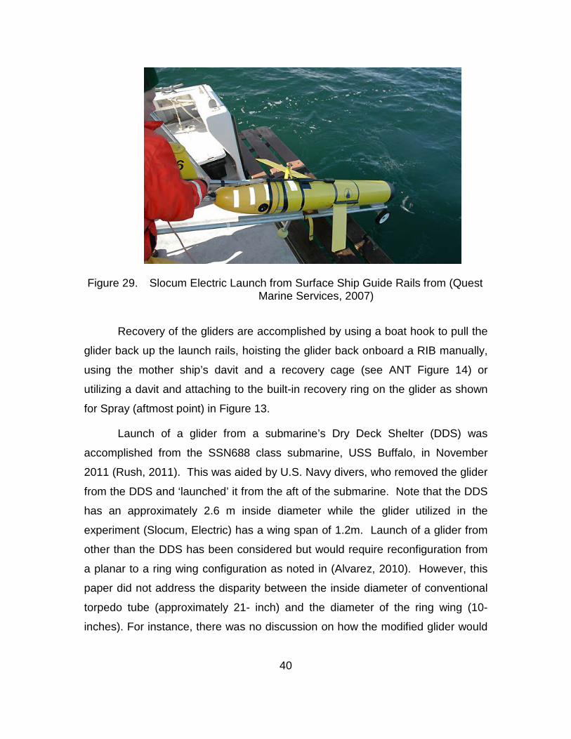
fixture and davit are shown in Figures 26 and 28, respectively. Slocum Electrics
launch from launch rails at the side of the vessel is shown in Figure 29.
39
Figure 27. Spray Glider Launch w/Strap & Davit from (Krupski, 2012)
Figure 28. Spray Glider Launch Fixture from (WHOI, 2012)
40
Figure 29. Slocum Electric Launch from Surface Ship Guide Rails from (Quest Marine Services, 2007)
Recovery of the gliders are accomplished by using a boat hook to pull the
glider back up the launch rails, hoisting the glider back onboard a RIB manually,
using the mother ship’s davit and a recovery cage (see ANT Figure 14) or
utilizing a davit and attaching to the built-in recovery ring on the glider as shown
for Spray (aftmost point) in Figure 13.
Launch of a glider from a submarine’s Dry Deck Shelter (DDS) was
accomplished from the SSN688 class submarine, USS Buffalo, in November
2011 (Rush, 2011). This was aided by U.S. Navy divers, who removed the glider
from the DDS and ‘launched’ it from the aft of the submarine. Note that the DDS
has an approximately 2.6 m inside diameter while the glider utilized in the
experiment (Slocum, Electric) has a wing span of 1.2m. Launch of a glider from
other than the DDS has been considered but would require reconfiguration from
a planar to a ring wing configuration as noted in (Alvarez, 2010). However, this
paper did not address the disparity between the inside diameter of conventional
torpedo tube (approximately 21- inch) and the diameter of the ring wing (10-
inches). For instance, there was no discussion on how the modified glider would
41
be supported within the torpedo tube structure. The recovery of the glider was
conducted at the surface utilizing a RIB. Future plans call for the divers to
recover the glider and return it to the DDS.
As an alternative to torpedo tube launch, launch from large diameter
missile or payload tubes appears feasible. Large diameter missile tubes are
present on SSBN and SSGN Class submarines and are scheduled to be installed
on SSN774 Class submarines starting with Block IV. Within the large diameter
tubes, supporting structure would be required to both secure the glider in the
large diameter tubes (~84” diameter) and allow vertical launch of the gliders.
Additionally, due to the limited buoyancy of underwater gliders, a launch pulse or
supplemental buoyancy may be required to ensure safe separation of the glider
from the platform.
D. CHAPTER SUMMARY
This chapter down selected from the underwater gliders surveyed in the
previous chapter in order to provide a comparison of the associated significant
architectural attributes. Although the underwater glider survey resulted in a
compilation of both conventional (buoyancy only), hybrid gliders (buoyancy and
propulsion) and winged gliders only conventional and hybrid gliders were
considered in the architectural attribute discussion. This was necessary to
restrain the scope of the resultant architectural attribute discussion. Additionally,
the conventional and hybrid gliders that were selected for the architectural
attribute discussion have significantly more at-sea time and either higher rates of
current production or near-term viable production than the flying wing glider
(Liberdade Zray). The gliders that were selected were:
• Spray
• ANT
• Slocum Electric
• Slocum Thermal
• Sea Glider
42
• eFolaga
• SeaExplorer The architectural attributes that were examined were comprised of the
following:
• Hull
• Buoyancy Mechanism
• Wing and Stabilizers Surfaces
• Control (pitch, roll, yaw)
• Sensors Wetted and Non-Wetted
• Communications/Navigation
• Launch and Recovery Each glider’s architectural attributes were examined in combination with all the
other selected fixed wing gliders. This information will now be utilized in the next
chapter in order to recommend an underwater glider architecture for use by the
U.S. Navy in actual forward deployed conditions.
43
IV. RECOMMENDATION OF UNDERWATER GLIDER ARCHITECTURE FOR U.S. NAVY USE
A. INTRODUCTION
This chapter delineates the recommendation(s) for an underwater glider
for use by the U.S. Navy. This section not only addresses the selection of the
architectural features for a U.S. Navy underwater glider but also provides
substantiating statements and rationale that justify said selection. The order of
selection of the architectural features is identical to that in chapter III and is
presented in the following order:
• Hull
• Buoyancy Mechanism
• Wing and Stabilizers Surfaces
• Control (pitch, roll, yaw)
• Sensors Wetted and Non-Wetted
• Communications/Navigation
• Launch and Recovery
Due to the potential deployment of the subject underwater glider from both
surface platforms and submarines two potential architectures are recommended
in the section, which follows.
B. GLIDER ARCHITECTURAL RECOMMENDATION
1. Hull
The hull for the glider is recommended to be of the type which matches
the hull’s compressibility to that of seawater as a function of depth. This will
reduce the energy required to be provided by the buoyancy system at the
deepest point in the dive cycle. Although additional analysis and testing is
required to match the compressibility of the hull to the compressibility of seawater
44
this is considered worth the extra effort and associated cost from a long term
operating cost perspective. A hull construct which matches seawater
compressibility reduces the amount of fluid which must be stored within the
pressure hull. This hull construct also reduces the amount of fluid which must be
pumped from within the pressure hull to outside the pressure hull as is normally
accomplished for stiff’ hulls to compensate for differences in hull compressibility
and seawater compressibility. Reducing the volume of fluid pumped across the
pressure/non-pressure hull boundary reduces the overall energy consumption for
each surface-to-depth cycle. This enables the residual energy to be utilized to
instead extend mission duration. The seawater compressibility matching hull
ultimately allows thinner hull structures which provides additional volume within
the hull due to the reduced heights of stiffening ribs and associated bulkhead
thicknesses.
To prevent issues associated with thru hull penetrations, thru hull
penetrations should either be eliminated or substantially minimized. This will
increase the reliability of the underwater glider which is significant as mission
persistence is an important characteristic of underwater gliders mission profile.
The hull should be comprised of various wet and dry sections, with the wet
sections provided at the furthest points forward and aft, respectively. This will
allow placement of flow thru sensors forward (i.e. flow CTD or forward looking
sonar) while the aft wetted sections would be used for the inflatable bladder of
the buoyancy system. Additionally, any minimal damage to these immediately
forward/aft wetted sections would not result in damage to the vehicle pressure
boundary. This would either allow continuing operation of the vehicle (with
possible reduced capability if allowable) or initiation of an emergency recovery
procedure.
2. Buoyancy Mechanism
The recommended buoyancy system is an electrically powered two pump
system with a booster pump feeding a main pump to pump fluid from a reservoir
45
within the vehicle’s dry pressure hull into an external bladder located in the
vehicle’s aft wetted section. This allows improved buoyancy system performance
at greater depths of vehicle operation as the pressure across each pump is less
than that across a single pump performing the identical function. (Obviously if
the glider were limited to shallow depth operation a single pump would suffice.
However, this thesis assumes a requirement for a multi-depth of use glider.)
The use of the thermal buoyancy system utilized by Slocum Thermal was
considered but deemed overly restrictive in regard to potentially restricting the
glider’s potential operating areas. As reported in the description of the thermal
buoyancy system in Chapter III, only 65% of the ocean is accessible to thermal
gliders (C. Jones, 2009). From a tactical usage standpoint this is untenable in
many of the current operational areas. Furthermore, the external tubes
necessary to increase overall thermal buoyancy engine efficiency are detrimental
in regards to debris accumulation on the glider. (Note that this is in addition to
any debris which may be accumulated and/or shed from the wings due to the
aftward rake of the wings.)
3. Wing and Stabilizer Surfaces
The U.S. Navy has both surface and sub-surface (submarine) assets in its
current ship inventory. Of the seven underwater gliders considered in the
architectural discussion any winged, finned or pump jet variants could be
launched from either surface platforms or from the DDS of submarines.
However, if launch from other than the DDS is considered on submarines (i.e.
torpedo tube launch) then only jet pump variants (i.e. eFolaga) would be
integratible. Therefore, an alternate architecture for propulsion would be required
for tube launch from submarine platforms. Noticeably, the limited mission
duration of the eFolaga, stated as 6 hours at maximum speed by GraalTech,
would not achieve the persistent presence capability of underwater gliders and
will not be considered further. Therefore, another vehicle (UUV) for achieving
these relatively short missions should be considered.
46
The relatively short aft fin configuration of SeaExplorer was also
considered but eliminated due to the limited lifting surfaces provided by the
relatively short horizontal stabilizer (or fin). Thus increased motion of the internal
weights (batteries) would be required for pitch control taking up valuable internal
volume that could be otherwise utilized.
For launch from surface platforms and submarine DDS structures (by
divers) a wing configuration similar to that utilized by the Slocum gliders is
recommended in concert with a controllable vertical stabilizer (discussed in the
vehicle control section which follows). This provides increased mission duration
when coupled with the recommended two-pump buoyancy system. Thus
relatively sharp edged wings similarly positioned, as shown on Slocum, would be
utilized for the U.S. Navy underwater glider. Incorporation of communications
antennas within the wings is not recommended as damage to the wings caused
by debris would interfere with the operational mission and eventual vehicle
recovery due to lack of communications. However, removable/replaceable wings
are recommended as this aids storage of the vehicles shipboard and allows for
rapid replacement of wings damaged during recovery operations.
4. Control (pitch, roll, yaw)
With use of the recommended fixed wings as described in Section 3,
Wings and Stabilizer Surfaces, vehicle pitch and roll control would be as
described for the Slocum Electric and Thermal gliders. Therefore, a portion of
the batteries used for buoyancy mechanism and sensor operation would be
axially displaced to alter the center of buoyancy/center of gravity separation
distance to provide vehicle pitch control. (Note some batteries are stationary in
this configuration and arranged to neutrally balance the center of gravity around
the center of buoyancy.) The buoyancy mechanism and wings would provide the
gross pitch control while the shift in center of buoyancy/center of gravity
separation distance would provide vehicle fine pitch control. This minimizes the
distance that the pitch mass has to move in the longitudinal direction which may
47
be acoustically beneficial. Roll control would be affected thru use of a
controllable vertical stabilizer at the upper aft portion of the glider. This provides
a significantly reduced turning duration as compared to fixed stabilizer gliders
with roll control established via a rotational mass within the glider (Wood, 2009).
This is particularly important in operations which require more frequent overlap
without wasting energy in turn creation (i.e. mine reconnaissance).
5. Sensors Wetted and Non-wetted
The recommended base sensors for the U.S. Navy underwater glider
include the following:
• Sensor: CTD – Conductivity, Temperature, Depth
o Use: Data input into the Sonar Equation for higher fidelity
Sound Velocity Profiles (SVP)
• Sensor: Altitude
o Use: Used by control system to keep glider a fixed distance
from ocean floor.
• Sensor: Compass
o Use: Input to the glider controller to maintain desired heading.
There are also a myriad of other sensors, which may be integrated into the
U.S. Navy underwater glider. An indication of this plethora of sensors is
provided in list format in Figure 30 and in hardware format in Figure 31.
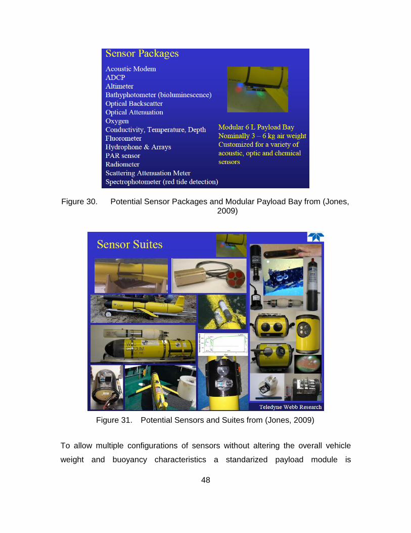
48
Figure 30. Potential Sensor Packages and Modular Payload Bay from (Jones, 2009)
Figure 31. Potential Sensors and Suites from (Jones, 2009)
To allow multiple configurations of sensors without altering the overall vehicle
weight and buoyancy characteristics a standarized payload module is
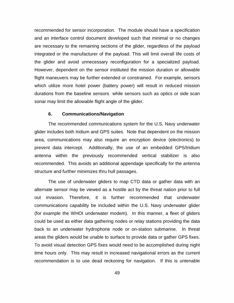
49
recommended for sensor incorporation. The module should have a specification
and an interface control document developed such that minimal or no changes
are necessary to the remaining sections of the glider, regardless of the payload
integrated or the manufacturer of the payload. This will limit overall life costs of
the glider and avoid unnecessary reconfiguration for a specialized payload.
However, dependent on the sensor instituted the mission duration or allowable
flight maneuvers may be further extended or constrained. For example, sensors
which utilize more hotel power (battery power) will result in reduced mission
durations from the baseline sensors while sensors such as optics or side scan
sonar may limit the allowable flight angle of the glider.
6. Communications/Navigation
The recommended communications system for the U.S. Navy underwater
glider includes both Iridium and GPS suites. Note that dependent on the mission
area, communications may also require an encryption device (electronics) to
prevent data intercept. Additionally, the use of an embedded GPS/Iridium
antenna within the previously recommended vertical stabilizer is also
recommended. This avoids an additional appendage specifically for the antenna
structure and further minimizes thru hull passages.
The use of underwater gliders to map CTD data or gather data with an
alternate sensor may be viewed as a hostile act by the threat nation prior to full
out invasion. Therefore, it is further recommended that underwater
communications capability be included within the U.S. Navy underwater glider
(for example the WHOI underwater modem). In this manner, a fleet of gliders
could be used as either data gathering nodes or relay stations providing the data
back to an underwater hydrophone node or on-station submarine. In threat
areas the gliders would be unable to surface to provide data or gather GPS fixes.
To avoid visual detection GPS fixes would need to be accomplished during night
time hours only. This may result in increased navigational errors as the current
recommendation is to use dead reckoning for navigation. If this is untenable
50
from a data or navigation standpoint then it is further recommended that an
Inertial Navigation Unit (INU) be included in the glider’s base sensors to provide
increased navigation accuracy between actual GPS fixes.
7. Launch and Recovery
The recommended architecture for launch of the U.S. Navy glider is
designing multiple features within the vehicle structure to allow; launch directly
over the side via RIB and two person team, lowering from surface vessel via
davit crane, from guide rails either astern or athwartships or vertically ascending
from a submarine’s large diameter missile or payload tubes. This will provide
maximum overall flexibility in the deployment of U.S. Navy underwater gliders
and allow them to be launched from all surface vessels, from the DDS of
submarines with diver assistance, and from large diameter missile or payload
tube equipped submarines.
No additional features are required for man-launch from the RIB.
However, hard points would be required for launch with a davit crane to protect
the vehicle hull, sensors and wings. The strengthened boundaries between hulls
sections could be used as hard points to lift the vehicle from the surface vessel
with the davit and also secure it in the DDS. An arrangement similar to that for
ANT shown in Figure 14 is envisioned for launch from a davit crane. For rail
launch an arrangement similar to that for Slocum in Figure 25 is recommended
for launch from astern/athwartships. Note that launch from deck mounted rails
(even with tilt features) requires that the overall vehicle withstand the impulse
loads occurring as the glider enters the water and may require additional analysis
and structural strengthening. For launch from a submarine’s large diameter
missile or payload tube a securing and release point on the afterbody similar to
that of Spray is recommended, see Figure 13
The recommended architecture for recovery is identical to that for launch
with similar features required in identical locations.
51
C. CHAPTER SUMMARY
This chapter provided the recommended architecture for a U.S. Navy
deployed underwater glider. Due to limited mission duration the eFolaga
underwater glider was not considered in the architectural recommendations. As
the main feature of underwater gliders is persistence on station or gathering data
the 6-hour mission duration for the eFolaga could be accomplished by other
existing UUVs contained within the UUV Master Plan (U.S. Navy, 2004). Specific
architectural recommendations made are shown in Table 1.
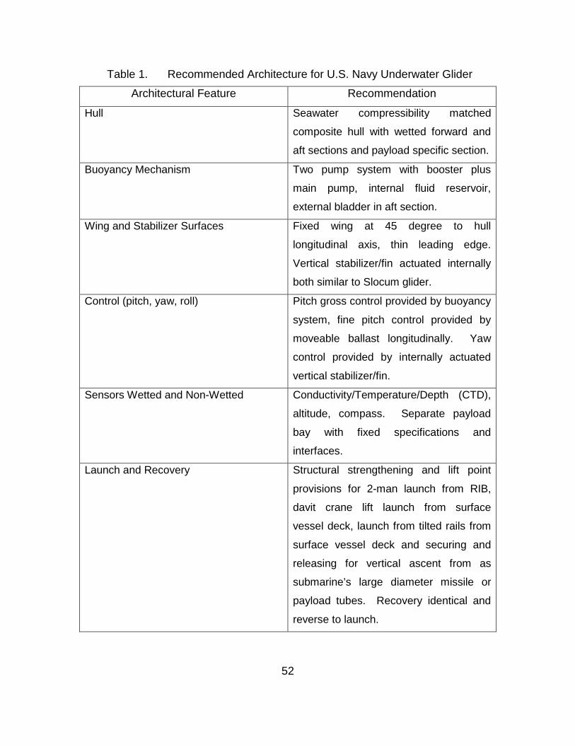
52
Table 1. Recommended Architecture for U.S. Navy Underwater Glider
Architectural Feature Recommendation
Hull Seawater compressibility matched
composite hull with wetted forward and
aft sections and payload specific section.
Buoyancy Mechanism Two pump system with booster plus
main pump, internal fluid reservoir,
external bladder in aft section.
Wing and Stabilizer Surfaces Fixed wing at 45 degree to hull
longitudinal axis, thin leading edge.
Vertical stabilizer/fin actuated internally
both similar to Slocum glider.
Control (pitch, yaw, roll) Pitch gross control provided by buoyancy
system, fine pitch control provided by
moveable ballast longitudinally. Yaw
control provided by internally actuated
vertical stabilizer/fin.
Sensors Wetted and Non-Wetted Conductivity/Temperature/Depth (CTD),
altitude, compass. Separate payload
bay with fixed specifications and
interfaces.
Launch and Recovery Structural strengthening and lift point
provisions for 2-man launch from RIB,
davit crane lift launch from surface
vessel deck, launch from tilted rails from
surface vessel deck and securing and
releasing for vertical ascent from as
submarine’s large diameter missile or
payload tubes. Recovery identical and
reverse to launch.
53
V. OPERATIONAL CONSTRAINTS AND CAPABILITIES OF UNDERWATER GLIDERS
A. INTRODUCTION
This chapter discusses the operational constraints and capabilities of
underwater gliders. Specifically, the discussion will focus on what constraints are
placed on underwater gliders due to their architectural configurations which
subsequently limit the operating envelope of the gliders. For example are they
constrained to specific operating areas due to limitations in depth or turning
ability. Furthermore, the capabilities of underwater gliders will be delineated in
regards to aiding the U.S. Navy’s warfighting capabilities. This will provide
insight into the military value that underwater gliders bring to the U.S. Navy.
Finally, a comparison will be made between capabilities and constraints of
underwater gliders as compared to the other UUV sizes notated in the U.S. Navy
Unmanned Undersea Vehicle Master Plan (U.S. Navy, 2004).
B. GLIDER CONSTRAINTS
The U.S. Navy glider proposed in Chapter IV has a number of constraints
that are inherent in all the gliders investigated in the architectural analysis of
Chapter III. The greatest constraint is that of having to surface to transmit data
recorded by the underwater glider to remote glider operator locations or nearby
U.S. naval units (via satellite or radio frequency link). This places the glider at
risk for detection and capture if the operating area is within threat sovereignty
territory. This could be avoided by the addition of an underwater acoustic
modem such as was noted, in Chapter III, as desirable for the U.S. Navy glider
proposed. However, others have noted underwater acoustic modems are
detrimental to glider endurance. “When they surface, gliders have a near-real-
time data transmission capability via the Iridium or Argos satellite
communications systems. Gliders which operate on minimal energy, do not use
acoustic modems as they would limit their endurance.” (Jane's, 2 JUN, 2011).
54
Thus, as with all glider sensor integrations, there is a constant tradeoff between
sensor utility and need and the endurance of the glider. Therefore, more energy
efficient acoustic modems would be needed or increased power density for a
given battery cell would be required.
Due to their fixed-wing, buoyant designs, gliders cannot maintain constant
position at a given depth (hover) in the presence of ocean current. Instead, when
current is present they may be pushed backward by the current (if it exceeds
forward speed of the vehicle) while still ascending/descending. Without
consideration for current it would be possible to design a control system such
that vertical hovering is maintainable. (This is a strong feature of the eFolaga
vehicle discarded in the architectural study due to its limited endurance of 6
hours at maximum speed.)
The current dead reckoning navigation scheme (with altitude sensing)
limits the ability of the glider to provide truly accurate position data with
accompanying oceanographic data. (Note this assumes that the current altitude
sensing is done forward of the vehicle to avoid collision with a rapidly rising sea
floor.) Additionally, navigational error growth may result in uncertain location with
potential future uses such as inclusion of an imbedded side-scan sonar for MCM
or object location. Incorporation of side-scan sonar would require significant
software and logic development to account for the angle of attack of the glider
relative to the sea floor. An option would be the incorporation of an inertial
navigation unit (INU) to provide more accurate navigation between GPS fixes at
the surface (when allowable).
Another constraint on gliders is that they must have sufficient water depth
below-the-surface and altitude above-the-bottom to accomplish their
characteristic saw-tooth glide pattern, see Figure 1. The ability of the glider to
avoid impact with the sea floor depends on altitude sensing and the
responsiveness of the control system to shift ballast and increase buoyancy as
55
the sea floor approaches the altitude set point (above the bottom). In this
context, the relatively slow forward speed of the glider enables the control system
adequate time to respond prior to bottom strike.
Existing underwater gliders were not designed with minimizing underwater
acoustics signatures as a requirement. Therefore, additional architectural
constraints and features may be necessary to avoid detection, tracking and
classification of the underwater gliders when conducting a Rapid Environmental
Assessment (REA) as part of an overall Mine Counter Measure (MCM) mission.
To avoid pump and motor acoustics (vibration, airborne noise) coupling with the
hull structure, design approaches such as isolation mounting of pumps and
motors from the hull structure may be necessary. Additionally, low noise
components such as bearings and gears may be necessitated. Potentially, a
noise budget could be allocated for each component of the glider and an overall
glider noise level established with the buoyancy mechanism and other systems
operational based on a mission profile. Alternately, acoustic noise cancellation
techniques could be used to cancel continuous duty cycle acoustics. Such
changes will require reassessment of overall vehicle weight and buoyancy and
also reassessment of the selection of the buoyancy system components.
Increases in overall vehicle size and weight may result as a byproduct of
incorporating noise reduction and isolation features.
An issue with incorporation of any additional sensors is retaining the pre-
existing endurance levels given the energy consumption of proposed sensors
relative-to/in-addition to current sensors. Current sensor selections typically
have extremely low power consumption and incorporate a ‘sleep’ mode wherein
the sensor is in a quiescent state, when unused, thus saving valuable energy.
For sensors that require a continuous or near continuous duty cycles such as
forward looking (obstacle avoidance/navigation) or side scan sonars (MCM) and
optical systems (bottom or debris imagery) this would be problematic, as vehicle
56
endurance would suffer significantly. This would eliminate the persistent
presence characteristic of gliders such that deployment of an alternate UUV
would be more appropriate.
The proposed underwater glider is constrained to be launched only from a
submarine’s DDS and with the aid of divers. This is due to the use of fixed
wings, whose span is significantly larger than the current U.S. Navy torpedo tube
diameters, therefore torpedo tube launch is not feasible. However, if semi-rigid
inflatable airfoils were utilized, similar to those on the Loitering Electronic Warfare
Killer (LEWK) (Erwin, 2001), repackaging an underwater glider for torpedo tube
launch may eventually prove feasible.
Although not specifically a constraint, the use of the dual pump buoyancy
system provides an all-depth buoyancy system but at the expense of added
weight and complexity at shallower operating depths. Obviously different
buoyancy pumping configurations could be feasible for gliders relegated to
operate within a specific depth range. However, having multiple configurations of
buoyancy pumping systems increases the glider logistics tail significantly.
C. GLIDER CAPABILITIES
The greatest capability of underwater gliders is their ability to maintain a
persistent and continuous presence in a specified operating area while gathering
and recording critical sensor data. Gliders are being used worldwide to capture
conductivity, temperature and depth readings in various operating areas ranging
from deep-ocean to shallow-littorals. In 2009, a Slocum Electric glider, from
Rutgers University, crossed the Atlantic Ocean in 221 days (Mother Nature
Network & Butler, 2009). Following the recent British Petroleum oil rig disaster
(Deep Water Horizon Oil Spill, 20 April 2011, Gulf of Mexico) underwater gliders
were used to locate and track oil by utilizing the onboard fluorometers which can
indicate the presence of oil (NOAA, 2010).
A fleet of gliders could also provide a low cost network for determining the
patrol patterns of threat submarine fleets. This is due to the inherent endurance
57
of gliders previously noted as 6 to 12 months in Chapter II’s underwater glider
survey. This would require that acoustic events be sensed and recorded by the
glider. Acoustic measurements would require the addition of conformal or
forwarded mounted hydrophones (ANT-LLC, 2010) to avoid self-noise issues
(those related to the glider itself). Alternately, a towed hydrophone array could
be deployed prior to or immediately following glider launch. Potentially automatic
target recognition (ATR) software could be developed such that the glider would
recognize a high value contact and relay the information shortly after the contact
cleared the area. Subsequently overlapping gliders would aid in development of
an overall submarine patrol track. This is somewhat similar to the plans for the
ONR flying wing Liberadade z-Ray (ONR, 2012). Similarly, a network of gliders
could provide coastal reconnaissance of any underwater approaches to the U.S.
shores and key infrastructures.
The myriad of potential sensor packages for gliders is of considerable
significance. This is especially true with the large number of humanitarian efforts
being undertaken by the U.S. military in recent years. In particular, continuous
detection and monitoring of radiation levels would prove invaluable in monitoring
local radiation levels if a disaster occurred at a nuclear plant which was located
on a coast. This application bridges the capability of the glider from military to
humanitarian applications and may provide useful in recognizing circulation
patterns of contaminated water from the Fukishima, Japan earthquake, tsunami
and subsequent nuclear disaster.
Gliders are classified as man-portable UUVs in accordance with the U.S.
Navy UUV Master Plan (U.S. Navy, 2004). This means they could be launched
quickly from small platforms such as a RIB or covertly from the DDS of a
submarine (Rush, 2011). These actions would allow underwater gliders to
provide REA data that can immediately utilized in MCM missions.
Within the U.S. Navy UUV Master Plan (U.S. Navy, 2004) the employment
of gliders is noted as part of the Communication/Navigation Network Node
(CN3). The CN3 is the “Enabling undersea node of the Net-Centric Warfare
58
Sensor Grid” (U.S. Navy, 2004) which will “Provide network connectivity across
multiple platforms and the ability to provide navigation aids on demand” (U.S.
Navy, 2004). Therefore, per the U.S. Navy UUV Master Plan, gliders are tasked
with gathering oceanographic data and providing undersea network conductivity.
Although valuable tasking given the high endurance of undersea gliders there are
numerous other tasks which could leverage this high endurance capability.
Thus, the U.S. Navy Master Plan fails to capitalize on the potential uses of
undersea gliders for coastal reconnaissance or submarine patrol trackers.
D. COMPARISON OF UNDERSEA GLIDERS AND OTHER AUVS IN TERMS OF OPERATIONAL CAPABILITIES AND CONSTRAINTS.
The basic comparison between an undersea glider and a AUV is between
a simple platform meant for oceanographic CTD measurements (glider) to that of
a complex vehicle made for a particular mission (AUV). Either gliders or AUVs
can be developed which are functional at either deep-ocean or shallow-littoral
depths. The significant departure in capabilities between gliders and AUVs is in
terms of overall mission endurance which drives many design aspects.
Underwater gliders have endurances in terms of months to years while AUV
endurance is in terms of hours or days. Vehicle endurance is a function of the
speed at which the mission is accomplished. Higher speed vehicles typically
consume energy at significantly higher rates. Thus, the actual mission speed of
completion requirement drives the determination if an underwater glider or
alternate AUV would be suitable for a given mission.
Currently the U.S. Navy is also pursuing the opposite end of the spectrum
from underwater gliders, large AUVs (UUV). This is an attempt to increase the
station time of the medium size UUVs bridging the capabilities between
underwater glider endurance and AUV capacity. For glider operations, operators
are most likely stationed remotely such as at the Stennis glider operations center,
Stennis Space Center, MS (Lammons, 2012). In contrast, UUVs normally have a
highly trained cadre that functions as a support and operations team for the
forward deployed vehicle. As stated in the capability section there is potential for
59
either coastal trip-wire implementation of gliders or use as detection and tracking
vehicles for locating threat patrol submarines. The low cost of gliders relative to
other AUVs allows a fleet of gliders to cover a given area versus less coverage
with fewer AUVs.
E. SUMMARY
This chapter discussed the operational constraints and capabilities of
underwater gliders. The dominant operational constraint of underwater gliders is
the need to transfer recorded data and receive instructions from the glider control
center. This requires the glider to surface and expose its antenna(s). To prevent
detection/capture in perceived threat waters, integration of an underwater
acoustic modem was discussed and found to reduce the underwater gliders
endurance. Therefore, more efficient underwater modems and higher power
density batteries are necessary.
The glider’s persistent surveillance and REA capability were discussed
and found highly relevant to near-term MCM missions. The persistence
surveillance capability was discussed relative to conducting constant surveillance
of U.S. coastal areas and in detecting and tracking threat patrol submarines.

60
THIS PAGE INTENTIONALLY LEFT BLANK
61
VI. SUMMARY AND CONCLUSIONS
A. SUMMARY
This thesis conducts an examination of the utility of underwater gliders within
the context of providing additional U.S. Naval capabilities. The specific research
questions posed and their subsequent answers are delineated below:
• What are the prevalent architectural features of currently existing commercial undersea gliders?
Based on a survey of available underwater gliders a compilation of
prevalent architectural features is developed. The specific key architectural
features or attributes selected for further analysis are:
• Hull
• Buoyancy Mechanism
• Wing and Stabilizers Surfaces
• Control (pitch, roll, yaw)
• Sensors Wetted and Non-Wetted
• Communications/Navigation
• Launch and Recovery
• How is undersea glider design driven by prevalent architectural features of currently existing commercial undersea gliders?
Based on the architectural analysis of the aforementioned key features, a
comparison of positive and negative factors affecting the overall underwater
glider architecture is performed and is fully described in Chapter III. Prevalent
architectural features driving underwater glider design include; type and material
of pressure hull (i.e. compressibility compensating or not, aluminum or
composite), buoyancy mechanism (full depth or limited depth capability), location
62
of wings on vehicle body (forward or aft of mid-body), method of achieving pitch,
yaw, and roll control (actuated surface(s) or wing location/buoyancy), placement
of general oceanographic/payload sensors (wet/dry or within separate payload
sensor bay), placement of communication antenna (in wings, stabilizer or trailing
appendage) and structural modifications necessary to support underwater glider
launch and recovery (lift or hard points).
• What are the paramount architectural features for a U.S. Navy undersea glider?
Specific, supporting, rationale for each recommended architectural feature
is discussed in Chapter IV and the proposed U.S. Navy underwater glider
architecture is delineated below as taken from Table 1.
• Recommended Hull: Seawater compressibility matched composite hull with wetted forward and aft sections and payload specific section.
• Recommended Buoyancy Mechanism: Two pump system
with booster plus main pump, internal fluid reservoir, external bladder in aft section.
• Recommended Wing and Stabilizer Surfaces: Fixed wing at
45 degree angle to hull longitudinal axis, thin leading edge. Vertical stabilizer/fin actuated internally - both similar to Slocum glider.
• Recommended Control (pitch, yaw, roll): Pitch gross control
provided by buoyancy system, fine pitch control provided by moveable ballast longitudinally. Yaw control provided by internally actuated vertical stabilizer/fin.
• Recommended Sensors Wetted and Non-Wetted:
Conductivity/Temperature/Depth (CTD), altitude, compass. Separate payload bay with fixed specifications and interfaces.
63
• Recommended Launch and Recovery: Structural
strengthening and lift point provisions for 2-man launch from RIB, davit crane lift launch from surface vessel deck, launch from tilted rails from surface vessel decks and securing and releasing for vertical ascent from a submarine’s large diameter missile or payload tubes. Recovery identical and reverse to launch.
• What are the operational constraints of undersea gliders?
The dominant operational constraint of underwater gliders is the necessity
to transfer recorded data and receive instructions from the glider control center
(or remote operator). This requires the glider to surface and expose its
antenna(s). To prevent detection/capture in perceived threat waters, integration
of an underwater acoustic modem is discussed and found to reduce the
underwater glider’s endurance. Therefore, more efficient underwater modems
and higher power density batteries are necessary for incorporation of underwater
acoustic modems in gliders without reduction from baseline endurance levels.
• What are the operational capabilities of undersea gliders?
The greatest operational capability of underwater gliders is their ability to
maintain a persistent and continuous presence in a specified operating area
while gathering and recording critical sensor data. The glider’s persistent
surveillance and REA capability are discussed and are highly relevant to near-
term MCM mission execution. Additional, potential, capabilities of a fleet of
underwater gliders are; use as U.S. coastal trip-wire warning system and also as
a low cost network for determining the patrol patterns of threat submarine fleets.
64
• How do undersea gliders compare to other types of AUVs in terms of operational capabilities and operational constraints? As compared to other AUV types, the underwater glider is capable of
operating nearly autonomously and for longer periods. This is due to the
operation of the glider from a remote command center and the significantly
longer duration capability of gliders. Overall manning is reduced as operation is
conducted from a remote underwater glider command center obviating the need
for a large cadre of vehicle specific operational and maintenance support
personnel. Additionally, a fleet of underwater gliders could provide undersea
network conductivity to various fleet assets at a substantially reduced cost as
compared to other AUVs.
B. AREAS TO CONDUCT FURTHER RESEARCH
This study should be re-evaluated once additional open-source
information becomes available on the Petrel underwater glider. Petrel is of
particular interest as it combines both forward motion due to wing lift and
propulsive means by propeller.
An additional area of interest would be the power consumption of various
sensor payloads relative to the reduction in glider endurance from the baseline
CTD configuration. This would include allow mapping specific glider/sensor
combinations to specific missions
Furthermore, to provide a submarine launched glider via the torpedo tube
environment, eFolaga and SeaExplorer should be re-evaluated once higher
energy density batteries become commercially available. Alternately, efforts
could be focused on development of a deployable wing concept that unfolds
post-launch.
A focused study on underwater acoustic communications via a distributed
underwater network system should be conducted to determine if a
communications network can be implanted insitu for future glider or other AUV
65
usage. Potential data transmit/receive rates and power consumption
considerations should be included in the study for both the glider and network.
Finally, a study on the potential for inclusion of an INU in the baseline
glider package should be considered to reduce the duration that the glider
remains detectable at the water’s surface. To be effective, this should be
coupled with the underwater communications study cited above.

66
THIS PAGE INTENTIONALLY LEFT BLANK
67
LIST OF REFERENCES
Alvarez, A. (2010). Redesigning the SLOCUM glider for torpedo tube launching. IEEE Journal of Ocean Engineering, 35(24), 984.
Alvarez, A., et al. (2009). Folaga: A low-cost autonomous underwater vehicle combing glider and AUV capabilities. Ocean Engineering, 36, 24.
ANT-LLC. (2010). ANT littoral glider - developing a new generation of gliders. Retrieved 5/28, 2012, from http://www.ant-llc.net/ant%20littoral%20glider.htm
ASCA - ALCEN. (2012). SeaExplorer - autonomous underwater vehicle glider. Retrieved 6/27, 2012, from http://www.underwater-gps.com/images/dynproduits/g48.pdf
AUVAC. (2012). Slocum thermal glider configuration. Retrieved 7/17, 2012, from http://auvac.org/configurations/view/51
BlueFin Robotics. (2012). Spray glider. Retrieved 5/28, 2012, from http://www.bluefinrobotics.com/products/spray-glider/
BlueFin Robotics. (2012). Spray glider specification sheet. Retrieved 7/11, 2012, from http://www.bluefinrobotics.com/assets/Downloads/Bluefin-Spray-Glider-Product-Sheet.pdf
Caffaz, A., et, al. (2010, March 2010). The hybrid Glider/AUV folaga. IEEE Robotics & Automation Magazine, , 31.
Carlowics, M., & Lippsett, L. (2008). Thermal glider use green energy to fly through the deep blue. Oceanus, 46(3), 12.
Davis, R., Eriksen, C., & Jones, C. (2002). Autonomous buoyancy-driven underwater gliders. In G. Griffiths (Ed.), The technology and applications of autonomous underwater vehicles (2002nd ed., pp. 37). London: Taylor and Francis.
Elvander, J., & Halgleish, F. (2011). The bluefin spray glider - recent activity. Retrieved 7/5, 2012, from http://ego2011.eu/doc/PDF-EGO/Wednesday%2016th/EGO%202011%20-%20Joshua%20Elvander.pdf
Erwin, S. (2001, June 2001). Electronic warfare drone developed with commercial technology. National Defense Magazine,
68
French, D. (2010). Analysis of unmanned undersea vehicle (UUV) architectures and an assessment of UUV integration into undersea applications. (Masters in Science in Systems Engineering, Naval Post Graduate School, Monterey, CA).
Graal Tech. (2011). Folaga AUV. Retrieved 7/29, 2012, from http://www.graaltech.it/documents/folaga.pdf
iRobot. (2012). IRobot 1KA SeaGlider. Retrieved 5/28, 2012, from http://www.irobot.com/en/us/robots/Maritime/Seaglider.aspx
Jane's Navy International. (2011). Reading the signs across ocean and atmosphere. Retrieved 8/15, 2012, from https://janes.ihs.com.libproxy.nps.edu/CustomPages/Janes/DisplayPage.aspx?DocType=News&ItemId=+++1208675&Pubabbrev=JNI
Jones, C. (2009). Environmental workshop WHOI. Retrieved 7/5, 2012, from http://media.umassp.edu/mattcenter/environmental-sensors/Teledyne_Jones.pdf
Jones, C., Allsup, B. & Altshuler, T. (2010). Slocum glider expanding the capabilities. Retrieved 7/22, 2012, from http://geos2.nurc.nato.int/mrea10conf/reports/pdf/Jones,%20Slocum%20Glider%20Expanding%20the%20Capabities.pdf
Kongsberg Maritime. (2012). Autonomous underwater vehicle - REMUS 6000. Retrieved 05/11, 2012, from http://www.km.kongsberg.com/ks/web/nokbg0240.nsf/AllWeb/481519DA1B0207CDC12574B0002A8451?OpenDocument
Krupski, A. (2012). FLoSEE 2011 expedition blog . Retrieved 7/22, 2012, from http://flosee2.wordpress.com/2011/09/26/sep-21-day-10/
Lammons, G. (2012). NMOC forecasting for bold alligator. Retrieved 8/17, 2012, from http://www.navy.mil/submit/display.asp?story_id=65340
Liquid Robotics.WaveGlider specification sheet. Retrieved 6/26, 2012, from http://liquidr.com/files/2012/06/Wave-Glider-0612.pdf
Mother Nature Network, & Butler, K. (2009). First unmanned underwater glider crosses the atlantic. Retrieved 8/16, 2012, from http://www.mnn.com/green-tech/research-innovations/stories/first-ever-unmanned-underwater-glider-crosses-the-atlantic
69
NOAA. (2010). NOAA, IOOS partners employing underwater gliders and surface radar to assist in gulf water sampling. Retrieved 8/16, 2012, from http://www.noaanews.noaa.gov/stories2010/20100630_ioos.html
ONR. (2012). Liberdade XRay advanced underwater glider. Retrieved 6/27, 2012, from www.onr.navy.mil
PMEL Engineering Development. (2012). Slocum electric gliders. Retrieved 7/5, 2012, from http://www.pmel.noaa.gov/edd/slocum_gliders.html
Quest Marine Services. (2007). Image gallery - science and engineering. Retrieved 7/22, 2012, from http://www.questmarineservices.com/gallery/scienceEngineering.html
Rush, D. (2011). Submarine makes first launch of an underwater glider. Retrieved 7/22, 2012, from http://www.spacewar.com/news/naval-05e.html
Seabird Inc. (16 Apr, 2012). CTD profiling instruments. Retrieved 05/11, 2012, from http://www.seabird.com/products/profilers.htm
Simonetti, P. (1992). SLOCUM GLIDER: Design and 1991 field trials. ().Webb Research Corporation.
Strommel, H. (1989). The slocum mission. Oceanography, 2(1), 22.
U.S. Navy. (2004). The navy unmanned undersea vehicle master plan ().United States Navy.
University of Washington. (2012). SeaGlider specifications. Retrieved 7/5, 2012, from http://www.apl.washington.edu/project/projects/seaglider/pdfs/seaglider_specifications.pdf
Webb Research, I. (2011). Teledyne webb research reaches second milestone of U.S. navy LBS-glider program. Retrieved 7/16, 2012, from http://www.webbresearch.com/newscenter/Reaches_Second_Milestone.aspx
Webb Research, I. (2012). Electric glider. Retrieved 5/28, 2012, from http://www.webbresearch.com/electricglider.aspx#
Webb Research, I. (2012). Thermal glider. Retrieved 5/28, 2012, from http://www.webbresearch.com/thermal.aspx#
Webb, D., C., Simonetti, P., J., & Jones, C., P. (2001). SLOCUM: An underwater glider propelled by environmental energy. IEEE Journal of Ocean Engineering, 26(4), 447.
70
WHOI. (2012). Spray glider. Retrieved 7/22, 2012, from http://www.whoi.edu/instruments/viewInstrument.do?id=1498
Wood, S. (2009). Autonomous underwater gliders . In A. Inzartsev (Ed.), Underwater gliders (pp. 499). Croatia: In-Tech.
Wu, J., & Wang, X. (2011). Dynamic modelling and motion simulation for a winged hybrid-drive underwater glider. China Ocean Engineering, 25(1), 97-112.
71
INITIAL DISTRIBUTION LIST
1. Defense Technical Information Center Ft. Belvoir, Virginia 2. Dudley Knox Library Naval Postgraduate School Monterey, California