naval postgraduate school - dtic.mil · naval postgraduate school report number ... user location...
TRANSCRIPT
NAVAL
POSTGRADUATE
SCHOOL
MONTEREY, CALIFORNIA
THESIS
Approved for public release; distribution is unlimited
MOBILE TRACKING AND LOCATION AWARENESS
IN DISASTER RELIEF AND HUMANITARIAN
ASSISTANCE SITUATIONS
by
Drew Q. Abell
September 2012
Thesis Advisor: Gurminder Singh
Thesis Co-Advisor: John Gibson

THIS PAGE INTENTIONALLY LEFT BLANK

i
REPORT DOCUMENTATION PAGE Form Approved OMB No. 0704–0188
Public reporting burden for this collection of information is estimated to average 1 hour per
response, including the time for reviewing instruction, searching existing data sources, gathering
and maintaining the data needed, and completing and reviewing the collection of information. Send
comments regarding this burden estimate or any other aspect of this collection of information,
including suggestions for reducing this burden, to Washington headquarters Services, Directorate
for Information Operations and Reports, 1215 Jefferson Davis Highway, Suite 1204, Arlington, VA
22202–4302, and to the Office of Management and Budget, Paperwork Reduction Project (0704–0188)
Washington DC 20503.
1. AGENCY USE ONLY (Leave blank)
2. REPORT DATE
September 2012
3. REPORT TYPE AND DATES COVERED
Master’s Thesis
4. TITLE AND SUBTITLE Mobile Tracking and Location
Awareness in Disaster Relief and Humanitarian
Assistance Situations
5. FUNDING NUMBERS
6. AUTHOR(S) Drew Q. Abell
7. PERFORMING ORGANIZATION NAME(S) AND ADDRESS(ES)
Naval Postgraduate School
Monterey, CA 93943–5000
8. PERFORMING ORGANIZATION
REPORT NUMBER
9. SPONSORING /MONITORING AGENCY NAME(S) AND
ADDRESS(ES)
N/A
10. SPONSORING/MONITORING
AGENCY REPORT NUMBER
11. SUPPLEMENTARY NOTES The views expressed in this thesis are those of the author and
do not reflect the official policy or position of the Department of Defense or the U.S.
Government. IRB Protocol number: N/A.
12a. DISTRIBUTION / AVAILABILITY STATEMENT
Approved for public release; distribution is unlimited
12b. DISTRIBUTION CODE
A
13. ABSTRACT (maximum 200 words)
Situational awareness is one of the most important aspects to a commander in
any type of mission, be it humanitarian relief, disaster recovery, or armed
conflict. Through the past several decades, with the use of technology, we have
been able to develop systems that help improve the commander’s situational
awareness of the mission. One of the major problems with this has been that
every organization uses different technology to communicate, which causes
interoperability issues and a lack of a Common Operational Picture (COP)
between them.
Commercial Off-the-Shelf (COTS) equipment that is relatively inexpensive,
easily obtainable, simple to operate, and rapidly distributable to different
organizations can help bridge this gap in the overall mission situational
awareness. The goal of this research is to explore how to effectively implement
Android-based devices to provide the tracking of team members and locations of
significant activities/equipment graphically through the use of GPS, Google
Maps, and custom overlays to increase situational awareness, thereby
constructing a COP to assist in disaster relief efforts.
14. SUBJECT TERMS Android Programming, Common Operating Picture,
Situational Awareness
15. NUMBER OF
PAGES
55
16. PRICE CODE
17. SECURITY
CLASSIFICATION OF
REPORT
Unclassified
18. SECURITY
CLASSIFICATION OF THIS
PAGE
Unclassified
19. SECURITY
CLASSIFICATION OF
ABSTRACT
Unclassified
20. LIMITATION OF
ABSTRACT
UU
NSN 7540–01–280–5500 Standard Form 298 (Rev. 2–89)
Prescribed by ANSI Std. 239–18

ii
THIS PAGE INTENTIONALLY LEFT BLANK

iii
Approved for public release; distribution is unlimited
MOBILE TRACKING AND LOCATION AWARENESS IN DISASTER RELIEF
AND HUMANITARIAN ASSISTANCE SITUATIONS
Drew Q. Abell
Captain, United States Army
B.A., Texas Tech University, 2003
Submitted in partial fulfillment of the
requirements for the degree of
MASTER OF SCIENCE IN COMPUTER SCIENCE
from the
NAVAL POSTGRADUATE SCHOOL
September 2012
Author: Drew Q. Abell
Approved by: Gurminder Singh
Thesis Advisor
John H. Gibson
Thesis Co-Advisor
Peter Denning
Chair, Department of Computer Science

iv
THIS PAGE INTENTIONALLY LEFT BLANK
v
ABSTRACT
Situational awareness is one of the most important aspects
to a commander in any type of mission, be it humanitarian
relief, disaster recovery, or armed conflict. Through the
past several decades, with the use of technology, we have
been able to develop systems that help improve the
commander’s situational awareness of the mission. One of
the major problems with this has been that every
organization uses different technology to communicate,
which causes interoperability issues and a lack of a Common
Operational Picture (COP) between them.
Commercial Off-the-Shelf (COTS) equipment that is
relatively inexpensive, easily obtainable, simple to
operate, and rapidly distributable to different
organizations can help bridge this gap in the overall
mission situational awareness. The goal of this research is
to explore how to effectively implement Android-based
devices to provide the tracking of team members and
locations of significant activities/equipment graphically
through the use of GPS, Google Maps, and custom overlays to
increase situational awareness, thereby constructing a COP
to assist in disaster relief efforts.

vi
THIS PAGE INTENTIONALLY LEFT BLANK

vii
TABLE OF CONTENTS
I. INTRODUCTION ..........................................1 A. BACKGROUND AND NEED ...............................1 B. FOCUS ............................................2
C. ORGANIZATION .....................................2
II. BACKGROUND AND RELATED RESEARCH ........................5 A. SITUATIONAL AWARENESS TOOLS .......................5
1. Military ....................................5 2. Civilian ....................................6
B. CLOUD COMPUTING...................................7 C. SPARCCS ..........................................8 D. CLIENT/SERVER ................................... 10
E. NATIVE SMARTPHONE SENSORS ........................ 10 F. SUMMARY ......................................... 11
III. DESIGN INFRASTUCTURE.................................. 13 A. ANDROID LOCATION MANAGER ......................... 13 B. SQLITE .......................................... 14 C. GOOGLE CLOUD .................................... 15
1. Google App Engine ........................... 15 2. Google Datastore ............................ 16
D. ANDROID MAP APPLICATION PROGAMMING INTERFACE
(API) ........................................... 17 E. OVERLAYS ........................................ 17 F. SUMMARY ......................................... 18
IV. IMPLEMENTATION ....................................... 19 A. USER LOCATION ................................... 19 B. DISSEMINATION OF USER LOCATION ................... 22 C. DISPLAY OF ACTIVE RESPONDER LOCATIONS ............ 23
D. LOCATE ACTIVE USERS .............................. 26 E. POINT OF INTEREST ICONS .......................... 27 F. USER SETTINGS ................................... 28 G. DETERMINE ACTIVE USERS ........................... 29 H. SUMMARY ......................................... 31
V. CONCLUSIONS AND FUTURE WORK ........................... 33 A. CONCLUSIONS ..................................... 33 B. FUTURE WORK ..................................... 33
LIST OF REFERENCES ........................................ 37
INITIAL DISTRIBUTION LIST.................................. 39

viii
THIS PAGE INTENTIONALLY LEFT BLANK

ix
LIST OF FIGURES
Figure 1. Design Flow ................................... 13 Figure 2. Location Undeterminable ....................... 20 Figure 3. User Location by GPS .......................... 21
Figure 4. User Location by Network Provider .............. 22 Figure 5. ArrayList Elements Skipped in For-Loop ......... 24 Figure 6. Responder Clicked ............................. 25 Figure 7. Responder Icons ............................... 26 Figure 8. Points of Interest Icons ...................... 28 Figure 9. Points of Interest Icons ...................... 29

x
THIS PAGE INTENTIONALLY LEFT BLANK

xi
LIST OF ACRONYMS AND ABBREVIATIONS
AGIS Advanced Ground Information Systems
APK Android Application Packages
BFT Blue Force Tracker
COTS Commercial Off-the-Shelf
COP Common Operational Picture
HTTP Hypertext Transfer Protocol
IaaS Infrastructure-as-a-Service
IDE Integrated Development Environments
OIF Operation Iraqi Freedom
PaaS Platform-as-a-Service
SPARCCS Smartphone-Assisted Readiness, Command and
Control System
SaaS Software-as-a-Service

xii
THIS PAGE INTENTIONALLY LEFT BLANK

xiii
ACKNOWLEDGMENTS
My wife, Marianne, for her love and support throughout
my career. Dr. Gurminder Singh and Professor John H.
Gibson, for their guidance and support with this research
and accompanying academic courses.

xiv
THIS PAGE INTENTIONALLY LEFT BLANK

1
I. INTRODUCTION
A. BACKGROUND AND NEED
One of the major aspects in military and disaster
response situation today is for commanders and team members
to have situational awareness. Commanders, team leaders,
and team members all need to be able to know where their
personnel are at all times. This will enable each member in
the field to effectively communicate the ground reality to
everyone else related to the mission. These attributes
combined with information from the headquarters element
make up what is known as a Common Operational Picture
(COP).
In the past, the COP has been maintained utilizing
cellular, radio, and computer-based communication methods
and by updating individual maps. A major problem with this
approach occurs when multiple organizations are involved in
the same mission and their lines of communications are
incompatible. Two relatively recent examples of these types
of issues are 9/11 and Hurricane Katrina [1]. During
Hurricane Katrina military forces and first responders had
issues communicating relief efforts with one another due to
a lack of a COP shared between the different entities.
September 11th had similar issues even between different
first responder organizations (police, firefighters, and
medics, etc.).
The ability to create an application that can provide
a COP on such a small mobile device would greatly increase
situational awareness for both the commanders and the
personnel on the ground. Additional benefits of using

2
smartphones are that they are Commercial Off-the-Shelf
(COTS) systems that are continually increasing in
capabilities with each iteration and easily obtainable.
B. FOCUS
The focus of this thesis is to demonstrate how to
effectively utilize both Android-based devices and cloud
computing to provide situational awareness. The main focus
is on utilizing mobile Android devices Global Positioning
Satellite (GPS) capabilities, mapping functions, and data
transfer to track and display user locations in the field
to provide situational awareness to the command center, as
well as to the individual users on the ground.
C. ORGANIZATION
The following chapters in this thesis are arranged and
discussed as follows:
Chapter II (Background and Related Research): The
second chapter of this thesis discusses current situational
awareness tools that are used by both military and civilian
organizations today. It describes the current command and
control system upon which this thesis builds advanced
capabilities. It also covers several of the technologies
that are used in this new type of system.
Chapter III (Design Infrastructure): The third chapter
gives a high-level look at how the information is gathered
and disseminated to other devices. It describes how each
piece of the system works to provide the user critical
situational awareness.

3
Chapter IV (Implementation): The fourth chapter goes
into detail on how the original system was altered to
incorporate location tracking. It covers which classes and
methods were added. It also gives examples of what a user
might see on their device while using it in a real world
mission.
Chapter V (Conclusions and Future Work): The fifth
chapter of this thesis gives an overall summary of what
this system provided originally and of what this system is
now capable. It also provides a few suggestions on how the
system can still be improved upon, and which capabilities
would make the system a truly robust system for disaster
relief and humanitarian assistance first-responders.

4
THIS PAGE INTENTIONALLY LEFT BLANK

5
II. BACKGROUND AND RELATED RESEARCH
A commanders ability to have an accurate perception of
his forces and area of concern is instrumental in any
operation. With today’s technology this same information
can be disseminated down not just to the sub-commanders but
to each individual team member on the ground. This section
covers the concept of situational awareness tools and the
technologies used with them.
A. SITUATIONAL AWARENESS TOOLS
The United States Army Training and Doctrine Command
defines Situational Awareness as:
Ability to have accurate and real-time
information of friendly, enemy, neutral, and
noncombatant locations; a common, relevant
picture of the battlefield scaled to specific
level of interest and special needs. [2]
Situational Awareness tools are now being used by both
military and civilian organizations. These tools help the
command more efficiently manage their personnel and
resources.
1. Military
One of the main technologies used today by the United
States military is the Blue Force Tracker (BFT). BFT is a
GPS-enabled system that graphically displays the location
of friendly forces. This system has the capability to send
and receive text for transmitting reports, battlefield
conditions, etc. It also has the ability for a user to
manually enter and update enemy forces.
6
This system was first fielded by the Army in late 2002
during the pre-invasion buildup of Operation Iraqi Freedom
(OIF). Soldiers were initially reluctant to use the system
because they believed it would just be another tool to help
micro-manage them.
BFT was later known for being one of the biggest
success stories of OIF and has since changed the way our
military conducts operations. BFT systems are now used by
both the Marine Corps and Air Force, as well as British
forces [3].
2. Civilian
The military are not the only ones using situational
awareness systems in operational environments. First
responders such as law enforcement, paramedics, fire
fighters, and homeland security are using these types of
systems as well.
One system used by first responders, made by Advanced
Ground Information Systems (AGIS), is called LifeRing.
LifeRing is an online group collaboration and communication
software system for crisis management. LifeRing provides
the capability for all first responders to know the
location of all other first responders by placing responder
icons on a graphical map display. These maps are stored on
the local device, or downloaded as needed if they are not
pre-positioned on the device. Users are capable of sending
text and making voice calls to other users. LifeRing also
allows for users to exchange photos and even videos with
other users. Each user can note the location of an event on
a map and have it sent to other users.
7
LifeRing is capable of being installed on PDAs, PCs,
and tablets. Originally, LifeRing was made to only be
compatible with Microsoft operating systems (Windows Mobile
6.5) but has recently been updated to function with most
mobile operating systems (e.g., BlackBerry, Android, and
Apple). Devices are connected together by a peer-to-peer,
many-to-many remote IP server. The LifeRing network can be
connected through both cellular or Wi-Fi connections [4].
Another system used in the private sector is GPS
Vehicle Tracking from FleetMatics. FleetMatics is a
software development company based out of Ireland. It is a
GPS-enabled system that provides situational awareness of
vehicles for private companies. These types of companies
include the service and distribution industries. The
system’s main purpose is to assist companies in improving
efficiency and increase productivity by providing
management with accurate and timely data of the locations
of their fleet.
The system works by attaching a small device to each
vehicle, which transmits its location and other information
to a server operated and maintained by Fleetmatics. The
server then has a web portal that allows users to view the
location and other data from each unit. There is also an
application that can be installed on either an Android or
iPhone that can be used to access the data [5].
B. CLOUD COMPUTING
The “cloud” is an expression referring to the use of
cloud computing, which in turn, is the term used for
providing computation, software, data access, and storage
services over the Internet instead of through a physical

8
device possessed by the user. The cloud gives people the
capability to utilize these services without needing to
understand how it works [6]. In essence, the resources are
consumed as a utility, just like electricity, and is
normally billed according to the amount of resources used.
This allows consumers to only pay for what they need,
purchasing more capacity or resources as required making
them elastic. This means they can scale up or down easily,
without major changes to their own infrastructure and
personnel, to meet demand [7].
The services that cloud computing provide can be
divided into three basic models. The first, Infrastructure-
as-a-Service (IaaS) provides virtual server instances.
Customers have the ability to access, build, start, and
stop their virtual servers and storage. This type of
service allows companies to expand rapidly to the size they
need while preserving cost. The second, Software-as-a-
Service (SaaS) makes available the hardware, software, and
interfaces to the user. These services can be accessed
through a browser or a thin-client. The last, Platform-as-
a-Service (PaaS), is where software and product development
tools are hosted by the provider. This allows for
developers to create and operate applications over the
Internet [8].
C. SPARCCS
Smartphone-Assisted Readiness, Command and Control
System (SPARCCS) is a command and control application
initially developed by Mike Asche and Niki Crewes to
demonstrate the operational capabilities that smartphones

9
and cloud computing provide. It provides for rapid
development and deployment capability using COTS equipment.
SPARCCS, in its current state, provides for an array
of useful features that can contribute to overall oversight
of a mission. Users can create, join, edit and view
missions, as well as create, edit, view, and delete points
of interest associated with particular missions. Images can
be captured edited, viewed and associated with the COP.
Information about each user belonging to a particular
mission can be displayed. GPS can be utilized to plot
missions, points of interest, and images on the COP.
The SPARCCS server-side was designed on the Platform-
as-a-Service model, defined earlier. The Platform-as-a-
Service model is perfect for a development environment
because it is robust, affordable, and scalable. SPARCCS is
currently running on Google’s APP Engine site. All
information collected is synchronized and stored in a cloud
database, also known as the Google Datastore. Google’s App
Engine Site also provides a web interface portal for users.
Users interact with the system in one of two ways. The
first is through the web portal, as previously stated. The
second is through an Android smartphone application. The
Android application allows for users in the field to take
advantage of the capabilities of their smartphone for use
in an operation. Users can easily add points of interest or
images to the COP using the built in camera. Location can
even be pinpointed with the use of the GPS antennas that
are common in most smartphones on the market. The COP is
easily displayed on the smartphone screen using Google Maps
and/or satellite imagery keeping the amount of space needed

10
to install the app minimal. Further, the use of “tiles”
associated with Google’s cloud computing allow for overlay
of custom diagrams, such as floor plans, on Google map
images.
D. CLIENT/SERVER
A common method of distributing information and data
services is the client/server computing architecture. The
client-server architecture is defined as “a network of
loosely coupled computers in which one or more computers
are designated as servers to provide specific services”
[9]. The most common types of usage for this architecture
are print, file, web, and database retrieval services.
The client/server architecture consists of four
components: client, server, network, and protocol. The
client is a host on the network that requests a server’s
content or service and is normally utilized by the end
user. The server is a host that runs one or more services
and shares its resources in response to requests or queries
by the client. The network is the infrastructure that
allows the communication between the client and the server.
The protocol is the standard that is used when exchanging
requests or responses between the client the server. An
example of a protocol is the Hypertext Transfer Protocol
(HTTP), which is normally used for web services [10].
E. NATIVE SMARTPHONE SENSORS
Smartphones carry a lot of power. Devices that may be
as small as a wallet may contain several different sensors,
a powerful processor, a large memory and plentiful storage
with a multitude of possibilities for use. These

11
smartphones are perfect for making every member of a field
team a collector of information, as well as a distributor
and consumer of such information.
Today’s smartphones have built-in cameras, with
resolution of more than 8 megapixels providing high-
definition quality, and a flash. This is better than some
stand-alone cameras on the market, and makes for one less
device to carry. Most top-selling phones include at least
three different antennas for transmitting and receiving
data communications: 3G/4G cellular, Wi-Fi, and Bluetooth
antennas. The 3G/4G cellular devices are perfect for
utilizing current commercial infrastructure and provide for
a larger coverage area. Wi-Fi antennas allow for simple,
short-range networks to be established with some central
gateway providing connection to the outside world, such as
a radio-equipped Wi-Fi hotspot. Bluetooth allows for
additional external wireless sensors to be connected to the
phone, as well as establishing mobile ad-hoc networks.
Smartphones also have accelerometers that are used to
detect any motion by the device. Furthermore, almost every
smartphone is GPS-enabled, which is perfect for obtaining
accurate location for incident reporting and even for
tracking individual user locations.
These sensors, combined with a dual or quad core
processor, 16 gigabytes or more of storage, and 1 to 2
gigabytes of RAM give them plenty of capability to be a
perfect field collection tool.
F. SUMMARY
With the use of smartphones and the cloud, SPARCCS can
create a powerful and cost efficient situational awareness

12
system that has the capability to utilize current
infrastructure networks and/or impromptu networks and allow
individual team members to communicate vital information to
the rest of their team and chain-of-command.

13
III. DESIGN INFRASTUCTURE
This chapter discusses the design, flow, and concepts
that will be used in SPARCCS to track and display
individual users and points of interest. This will include
Android LocationManager, SQLite database, Google App Engine
and Datastore, Android Map API, and overlays. Figure 1 is a
diagram that shows the basic components that are used in
the process.
Cloud Services
Datastore
APPEngine
GPS
Smartphone
SQLiteAPP
DisplayGPS
Smartphone
SQLiteAPP
Display
Figure 1. Design Flow
A. ANDROID LOCATION MANAGER
The first task in the design of tracking individuals
and asset locations is for each element to determine its
position. Smartphones include built in GPS, cellular, and
Wi-Fi antennas.

14
Through the use of these antennas and the
LocationManager class, applications can determine their
device position. Giving permission for an application to
ACCESS_FINE_LOCATION allows the LocationManager the ability
to activate the phone’s GPS antenna and acquire its
position. Giving permission for an application to
ACCESS_COARSE_LOCATION allows the LocationManager the
ability to determine its location based on local cell
towers and/or Wi-Fi access points [11]. Both methods can be
used to acquire the location and automatically switched
between the two methods as one type loses or regains its
position. If both methods are enabled the priority will be
given to the GPS acquired location.
Once the application has determined its location
through the use of the GPS antenna or network provider,
this data must be stored to the local database of the
phone.
B. SQLITE
To track the user’s own location as well as the
locations of the other users accessing the system, there
must be a place to store this data. The SPARCCS mobile
application uses an SQLite database to store information
about responders on the phone. SQLite is an open source
database that is embedded into every version of the Android
operating system.
SQLite is small, fast, and reliable. SQLite databases
do not have a separate server process like most SQL
databases. Read and writes are made directly to ordinary
15
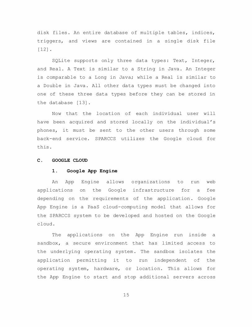
disk files. An entire database of multiple tables, indices,
triggers, and views are contained in a single disk file
[12].
SQLite supports only three data types: Text, Integer,
and Real. A Text is similar to a String in Java. An Integer
is comparable to a Long in Java; while a Real is similar to
a Double in Java. All other data types must be changed into
one of these three data types before they can be stored in
the database [13].
Now that the location of each individual user will
have been acquired and stored locally on the individual’s
phones, it must be sent to the other users through some
back-end service. SPARCCS utilizes the Google cloud for
this.
C. GOOGLE CLOUD
1. Google App Engine
An App Engine allows organizations to run web
applications on the Google infrastructure for a fee
depending on the requirements of the application. Google
App Engine is a PaaS cloud-computing model that allows for
the SPARCCS system to be developed and hosted on the Google
cloud.
The applications on the App Engine run inside a
sandbox, a secure environment that has limited access to
the underlying operating system. The sandbox isolates the
application permitting it to run independent of the
operating system, hardware, or location. This allows for
the App Engine to start and stop additional servers across

16
the cloud to meet traffic needs while simultaneously
distributing web request to the associated servers [14].
Data is exchanged with the App Engine through HTTP
requests. The App Engine stores the information in the
datastore, described below.
2. Google Datastore
The datastore is a scalable storage location for web
applications with no planned downtime. Objects in a
datastore are called entities. An entity has one or more
named properties and those named properties can have one or
more values. The data types for these properties can be:
integers, floating-point numbers, strings, dates, binary,
and more.
A datastore is different from traditional relational
databases in that it uses a distributed architecture and is
able to scale automatically. Datastore writes scale by
automatically distributing data as needed. The reads scale
because the only queries supported are the queries that
scale with the size of the result. This means the
performance for 100 queries is the same over a thousand
entities or a million [15].
Once the information has been placed in the datastore,
it can be queried and retrieved by the SPARCCS application
on user smartphones. Once the user has received the new
information from the datastore and has saved it to the
local SQLite database, the information can be used to
graphically display each user.

17
D. ANDROID MAP APPLICATION PROGAMMING INTERFACE (API)
Once the SQLite database on the local device has been
updated with information on other users, it is now possible
to display them graphically on a map or satellite image.
Google allows Android applications to access their map
repository and display them using the Android Maps API.
To be able to access the Google Maps repository, the
application must have a Maps API Key. The Key can be
obtained by registering an MD5 fingerprint of the
certificate that is used to sign the application. A
separate key is needed for developmental builds (installed
directly from Integrated Development Environments [IDE])
and release builds (signed Android Application Packages
[APK]).
The Maps API includes the basic function for viewing
maps on a touch screen. It includes the ability for the
user to use touch gestures to pan and zoom in and out on
the map. Through the use of the Maps library, satellite
images can be displayed on top of the map as well.
Once the application has the capability for displaying
map or satellite images, the next step is to display the
user locations on the map. This is done through overlays.
E. OVERLAYS
When it is time to actually place icons on the map to
represent the locations of the other users or points of
interest is analogous to acetate overlays used for planning
missions in the military, to plot movements and enemy
locations on top of hard-copy maps. Another analogy would
be in construction to show water and power lines on

18
blueprints by having them drawn on translucent paper and
placed on top of the blueprints.
Next an itemized overlay will be created that uses an
arrayList to hold each object that will be displayed. The
data needed for each item can then be gathered from the
local database and placed into the arrayList in the
itemized overlay. Once the itemized overlay is ready it is
added to the overall map overlay. Creating itemized
overlays and adding them to a master overlay allows us to
dynamically choose which itemized overlays we wish to
display.
As the database is updated with new positions for the
different users the overlay can be updated. This is done by
creating a method that is called every time the database is
updated. This method will reload the itemized overlay with
the current information from the database, clear the
overlay currently displayed on the map, and then redraw the
itemized overlay so that it is viewable once again.
F. SUMMARY
This chapter summarized the flow of how object
locations that are gathered through the use of the
smartphone will be gathered, distributed, and plotted on
the local devices. The built in antennas on smartphones
provide a great capability for easily gathering the
location of the device. The next chapter details how these
capabilities are implemented into the SPARCCS system.

19
IV. IMPLEMENTATION
This chapter discusses the implementations of the
responder tracking and display features of the SPARCCS
mobile application. This includes determining the device
location, dissemination of location to other devices, how
and which icons are plotted on the map, how point of
interest icons are determined, and how responders are
determined to be active.
A. USER LOCATION
As previously stated, to access the user’s device
location we must use the LocationManager class. An instance
of the LocationManager class, locManager, is created during
the onCreate() portion of the main activity file of the
SPARCCS mobile application. This gives the application the
ability to access the system location services.
Next, an instance of the LocationListener class is
needed to receive notification from the locManager of when
the location has changed; this instance was named
MyLocationListener. MyLocationListener is not just an
instance of LocationListner but of a custom class of
LocationListener. This custom class was created so that the
location is determined by the GPS receiver subsystem first,
and if that fails, to obtain the location from the network
provider. It also allows for custom messages to be
displayed in the event that the current location is
undeterminable (Figure 2) or if the location setting needs
to be altered in the phone.

20
Figure 2. Location Undeterminable
To start using the location data that is now enabled,
an instance of the MyLocationOverlay class is created,
myLocationOverlay. The myLocationOverlay can then be
displayed on the map using the following statement:
mapView.getOverlays().add(myLocationOverlay);
21
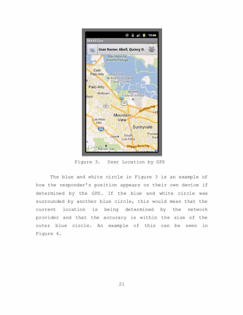
Figure 3. User Location by GPS
The blue and white circle in Figure 3 is an example of
how the responder’s position appears on their own device if
determined by the GPS. If the blue and white circle was
surrounded by another blue circle, this would mean that the
current location is being determined by the network
provider and that the accuracy is within the size of the
outer blue circle. An example of this can be seen in
Figure 4.

22
Figure 4. User Location by Network Provider
B. DISSEMINATION OF USER LOCATION
The current location of the device is gathered using a
method named myLocationToDB. This method first creates an
instance of the ResponderClient class with the user’s
current data. Then it gathers the GeoPoint, a single
variable that holds both latitude and longitude in
microdegrees, of the device by issuing the following
command:
GeoPoint point = myLocationOverlay.getMyLocation();
Once the GeoPoint has been acquired, both the latitude
and longitude are extracted and placed in separate
variables for entry into the database. They are then placed

23
into the instance of the ResponderClient that was created.
The instance of the ResponderClient is then used to update
the information of the current user to the local database.
The next time the mobile device synchronizes to the
App Engine, the latest latitude and longitude values are
updated in the datastore on the Google cloud. During this
synchronization, any new location data for other users is
received and stored in the local database.
C. DISPLAY OF ACTIVE RESPONDER LOCATIONS
To display other responders on the map, a list of all
the active responders must be created. To do this, the
buildResponderClassList() method is used. This method
builds an ArrayList of type ResponderClient that only
contains responders that have joined the same mission and
are currently active. Active users are defined as devices
that have synchronized to the app engine within 15 minutes.
The buildResponderClassList() method first takes an
ArrayList of type ResponderClient and loads it with all the
responders listed in the local database. Next, the current
user’s mission is compared to each responder mission in the
previously created ArrayList using a for-loop. If both the
responders and the current user’s mission matches and the
responderLoggedIn field for that responder is set to “true”
then a copy of that responder is added to a second
ArrayList. This second ArrayList contains the responders
that will be displayed.
If the second ArrayList were not used and responders
that did not meet the criteria were just removed from the

24
ArrayList during that iteration of the for-loop,
a responder may not be compared against the criteria
(Figure 5).
Figure 5. ArrayList Elements Skipped in For-Loop
After the for-loop is complete, the final step in
creating the ArrayList is to remove the current user. This
is done so that the user is not displayed twice on the map.
The method responderListRemoveUser() is used for this. The
responderListRemoveUser() method uses a for-loop to compare
the user name with the respondername field in the
ArrayList. If there is a match, the entry is removed from
the ArrrayList.
Once the ArrayList of all the users has been created,
it can now be used to populate the map with icons
representing the locations of these active users. This is

25
done through the method responderDrawOverlay(). The
responderDrawOverlay() method uses an itemized overlay so
that information about each responder can be displayed when
the icon is clicked on the map and different icons can be
used for each responder based upon their type. Figure 6 is
an example of what is displayed when a responder’s icon is
clicked.
Figure 6. Responder Clicked
The ArrayList is iterated through using a for-loop to
perform the following functions. The latitude and longitude
are extracted and used to create a GeoPoint. This GeoPoint
represents where the icon will be displayed on the map.
Then, an overlay item is created with the GeoPoint and any

26
other information that is going to be displayed about the
responder. Then, the responder type is compared to
determine which icon will be set for this user. Figure 7
shows responders displayed on the map with different color
stars representing them as three different types of
responders. A green represents military, red for fire
protection, blue for law enforcement, white for medical
corps, and purple for humanitarian assistance.
Figure 7. Responder Icons
D. LOCATE ACTIVE USERS
Once the responders are plotted on the map they can be
located by clicking the responder’s button in the top

27
right-hand corner of the screen. Once clicked, a dialog box
will appear listing all active users who are a part of the
current user’s mission. Click the name of the responder you
want to locate and the map will move and center on the
location of that user. To center the map on the current
user location, click the button at the top center of the
screen with the user name on it.
This functionality is provided by the
goToResponderLocation() and goToMyLocation() methods,
respectively. These methods use the built in
MapView.getController().animateTo(GeoPoint) method to
center the map on these locations. These methods also set
the zoom of the map based on the default zoom level
selected in the application setting.
E. POINT OF INTEREST ICONS
Displaying points of interest using different icons is
done similarly to that of displaying responders’ icons. The
points of interest form from the original SPARCCS mobile
code was altered to only allow choices from a spinner
object for the description. A spinner object resembles a
drop-down list in HTML. This allowed for the description
field to be evaluated and a specific icon to be set based
on this field. Figure 8 shows different icons for the six
points of interest on the map. The flame icon representing
a fire location, the water drop representing a water cache,
the fork and spoon representing a food cache, and a the
flag icons used to represent other types of points of
interest.

28
Figure 8. Points of Interest Icons
F. USER SETTINGS
The application settings menu is accessed by pressing
the device’s menu button and selecting settings. This
displays the application settings. This display and the
variables used in it are created using the shared
preferences library included in the Android operating
system. Shared preference allows for the storage of private
primitive data in key-value pairs. Accessing a variable in
shared preference is faster than accessing a locally stored
file.

29
Figure 9. Points of Interest Icons
Under the setting menu, the current users name and the
server the application is accessing are displayed (Figure
9). From here the user can change the update intervals and
default zoom levels.
G. DETERMINE ACTIVE USERS
Active users are determined by the Google App Engine.
Although the SPARCCS mobile application uses the
responderLoggedIn field to determine if the user’s icon
will be displayed, it is the app engine that sets this
field. When a user logs-in from the SPARCCS mobile
application the reponderLoggedIn field is set to “True” for
that responder in the datastore in the Google cloud.

30
Whenever the responder’s device synchronizes with app
engine again, the field is set to “True,” ensuring the user
is still active.
A responder becomes inactive if their device does not
synchronize with the app engine after a specified amount of
time. This is done by creating a timestamp field in the
datastore. This timestamp field is updated with the current
time whenever the user logs in or synchronizes with the app
engine. The time used for the timestamp is generated from
the app engine and not the mobile applications. This is
done to prevent inaccuracies in timing and to be able to
account for time zone variations. The timestamp field is
checked against the current time every 15 minutes (this
time can be modified inside the app engine code). If during
this check the difference in the current time and the
timestamp exceeds the specified amount of time the
responderLoggedIn field is set to “False” for that
responder. This is needed because continual transmissions
between the app engine and the device are not maintained
between synchronization intervals.
Google App Engines run primarily on front-ended
instances. This means that the server-side code is running
and scaling dynamically, based on incoming requests, and
working in a reactive state. So, once a device connects to
synch with the application, the processes are then
preformed. To create a way for a frontend instance to be
called to compare responders’ timestamps, the SPARCCS app
engine utilizes a “cron” job. A cron is a time-based job
scheduler in Unix operating systems. This cron job allows
for a regularly scheduled task to be performed at defined

31
times or intervals. The cron job is set to execute the
SPARCCS AutoLogoutCheckServlet every 15 minutes. This
effectively sets responders to an inactive state so they
are not displayed on the map when not currently
participating in the mission.
H. SUMMARY
This chapter summarized the implementation of the
responder tracking capability of the SPARCCS mobile
application. This situational awareness capability adds to
a units overall potential effectiveness during a mission.

32
THIS PAGE INTENTIONALLY LEFT BLANK

33
V. CONCLUSIONS AND FUTURE WORK
A. CONCLUSIONS
The SPARCCS system was designed to provide a COP to
the command center down to the individual responder. Users
were able to disseminate information to the command center
as well as other responders in a relatively quick fashion
and have them depicted graphically on a map.
With the inclusion of the tracking capability into the
SPARCCS system, the situational awareness of the all
members supporting the mission is significantly increased.
Users can now see the proximity of other responders on
their mobile devices. This ability allows for more
effective use of personnel by the command center and by the
team leaders on the scene.
SPARCCS, in its present state, provides a vast set of
capabilities to its users utilizing the cloud and COTS
equipment that is relatively inexpensive, easily
obtainable, simple to operate, and rapidly deployable to
different organizations. This can help bridge the gaps in
the overall mission situational awareness we discussed in
Chapter I.
B. FUTURE WORK
This thesis extended the capabilities of the original
SPARCCS system. The addition of the mobile tracking
capability to the system enhances the overall situational
awareness of the mobile responders as well as the command
center. The system is close to being a fully featured

34
command and control suite but could use a few more
capabilities to be more effective. Below are a few
recommendations.
Mobile-to-Mobile Device Synchronizing — Allowing
for a mobile device to act as a server to
synchronize other mobile devices would alleviate
traffic on the long haul connection for missions
with limited bandwidth capabilities or restricted
access to the Internet. This could also allow for
team members to stay synchronized among a local
group if connectivity to the Google cloud is
temporary lost.
Push Capability — Currently, the SPARCCS system
uses http requests to send and receive
information. This means the mobile device is only
updated when it requests updates from the app
engine and not when updates are made to the
datastore. This creates some lag from when the
data in the cloud is updated and when the mobile
users interface is updated. If updates to the
server were disseminated using push capability,
mobile devices could display information at close
to real time.
Responder Route Logging — The ability to see
where a responder has been would be useful for
analysis of mission operations after they are
complete.
Messaging — Communicating with other team members
during operations is essential. Having the
35
capability to send a simple text message to
another team member by just tapping on their icon
would give them a rapid and easy way to
communicate.
Notifications — As new users join missions or new
points of interest are added to the map, the user
may not notice immediately. Adding notifications
would provide a way to indicate to the user that
something has been changed/updated to the current
mission.

36
THIS PAGE INTENTIONALLY LEFT BLANK

37
LIST OF REFERENCES
[1] R. Miller, Hurricane Katrina: Communications &
Infrastructure Impacts. Fort McNair: National Defense
University, 2007.
[2] “Force XXI Operations,” TRADOC pamphlet 525–5, U.S.
Army Training & Doctrine Command, Fort Monroe, VA,
1994.
[3] R. Tiron, National Defense Industrial Association,
"Army’s Blue-Force Tracking technology Was a tough
sell" December 2003,
http://www.nationaldefensemagazine.org/archive/2003/De
cember/Pages/Armys_Blue3685.aspx.
[4] AGIS, “Advanced Ground Information Systems,”
http://www.agisinc.com/.
[5] Fleetmatics, “GPS vehicle tracking from FleetMatics,”
2012, http://www.fleetmatics.com.
[6] “Cloud computing,” in Wikipedia.
http://en.wikipedia.org/wiki/Cloud_Computing.
[7] "Infographic: The future of the cloud," eyeOS Blog,
http://blog.eyeos.org/en/2011/11/18/infographic-the-
future-of-the-cloud/.
[8] M. Rouse, “Search cloud computing,” December 2010,
http://searchcloudcomputing.techtarget.com/definition/
cloud-computing.
[9] I. Englander, The Architecture of Computer Hardware
and Systems Software. Hoboken, NJ: John Wiley & Sons,
2003.

38
[10] T. R. Kochtanek, “Client-Server model,”
http://web.missouri.edu/~heink/7301/inet/clientserver.
html.
[11] Android Developer Reference, "Reference:
LocationManager," August 2012,
http://developer.android.com/reference/android/locatio
n/LocationManager.html
[12] SQLite, “About SQLite,” http://www.sqlite.org/.
[13] L. Vogel, “Android SQLite database and content
provider,” 16 March 2012,
http://www.vogella.com/articles/AndroidSQLite/article.
html.
[14] Google Developers, “Google App Engine,” 11 July 2012,
https://developers.google.com/appengine/docs/whatisgoo
gleappengine.
[15] Google Developers, “Datastore Overview,” 26 June 2012,
https://developers.google.com/appengine/docs/java/data
store/overview.
39
INITIAL DISTRIBUTION LIST
1. Defense Technical Information Center
Ft. Belvoir, Virginia
2. Dudley Knox Library
Naval Postgraduate School
Monterey, California
3. Head, Information Operations and Space Integration
Branch
PLI/PP&O/HQMC
Washington, D.C.