navigation for indoor robot: straight line movement via...
TRANSCRIPT

Research ArticleNavigation for Indoor Robot Straight Line Movementvia Navigator
Chaozheng Zhu 1 Ming He 12 Pan Chen3 Kang Sun4
Jinglei Wang 5 and Qian Huang36
1College of Command and Control Engineering The Army Engineering University of PLA Nanjing 210007 China2Institute of Network Information Institute of Systems Engineering Academy of Military Sciences Beijing 100071 China3College of Computer and Information Hohai University Nanjing 211100 China4College of Energy and Electrical Engineering Hohai University Nanjing 211100 China5School of Electronic and Optical Engineering Nanjing University of Science and Technology Nanjing 210094 China6Key Laboratory of Symbol Computation and Knowledge Engineering of Ministry of Education Jilin University Jilin 130012 China
Correspondence should be addressed to Ming He paper review126com
Received 4 July 2018 Accepted 2 September 2018 Published 24 September 2018
Academic Editor Simone Bianco
Copyright copy 2018 ChaozhengZhu et alThis is an open access article distributed under the Creative Commons Attribution Licensewhich permits unrestricted use distribution and reproduction in any medium provided the original work is properly cited
Due to the need of zigzag overlay strategy long-term linear motion is essential for sweep robot However the existing indoor sweeprobot navigation algorithm hasmany problems for instance algorithm with high complexity demands high hardware performanceand is incapable of working at night To overcome those problems in this paper a new method for indoor robot Straight LineMovement via Navigator (SLMN) is proposed to ensure long linear motion of robot with an acceptable error threshold and realizemultiroom navigation Firstly in a short time robot runs a suitable distance when it is covered by navigatorrsquos ultrasonic sensor Wecan obtain a triangle with twice the distance between navigator and robot and the distance of robot motion The forward angle ofthe robot can be conveniently obtained by the trigonometric functions Comparing the robotrsquos current angle with expected anglethe robot could correct itself and realize the indoor linear navigation Secondly discovering dozens of the magnitude gaps betweenthe distance of robot run and the distance between navigator and robot we propose an optimized method using approximatescaling which increases efficiency by nearly 708 Finally to realize multiroom navigation we introduce the conception of thedepth-first search stack and a unique encode rule on rooms and navigators It is proved by extensive quantitative evaluations thatthe proposed method realizes indoor full coverage at a lower cost than other state-of-the-art indoor vision navigation schemessuch as ORB-SLAM
1 Introduction
Traditional low cost sweep robot used the random mode ofsweeping with small coverage area low cleaning efficiencyand easy collision Adopting the shape of Z full coveragealgorithm [1] can effectively reduce the disadvantage ofrandom sweeping but robot must run linearly if the fullcoverage algorithm can work steadily [2 3] It could worknormally based on an inertialmeasurement unit (IMU) [4 5]but with the data from both sensor and PID correcting itsdirection it is not enough to realize its indoor localizationDue to accumulated errors of sensors wheel mechanicalinaccuracy and the slide problem sweeping robotwould drift
away so researchers start the indoor navigation system [6]research
Rodas et al proposed an optimal Bayesian fusion andlocalization algorithm based on Bluetooth positioning data[7] However Bluetooth location error is still serious deploy-ment cost is huge and the result is not satisfactory Lin etal proposed a fingerprint location system based on Wi-Fi[8] which is a sample of signal intensity and preconstructa radio map use the information of Wi-Fi cover and readdata from accelerometer reliably However a great quantityinitial work should be finished before using it and the effectis not very well Fuentes-Pacheco et al proposed vSLAM(visual Simultaneous Localization and Mapping) [9ndash13]
HindawiMathematical Problems in EngineeringVolume 2018 Article ID 8419384 9 pageshttpsdoiorg10115520188419384
2 Mathematical Problems in Engineering
Infrared
ultransonic
Navig-ator
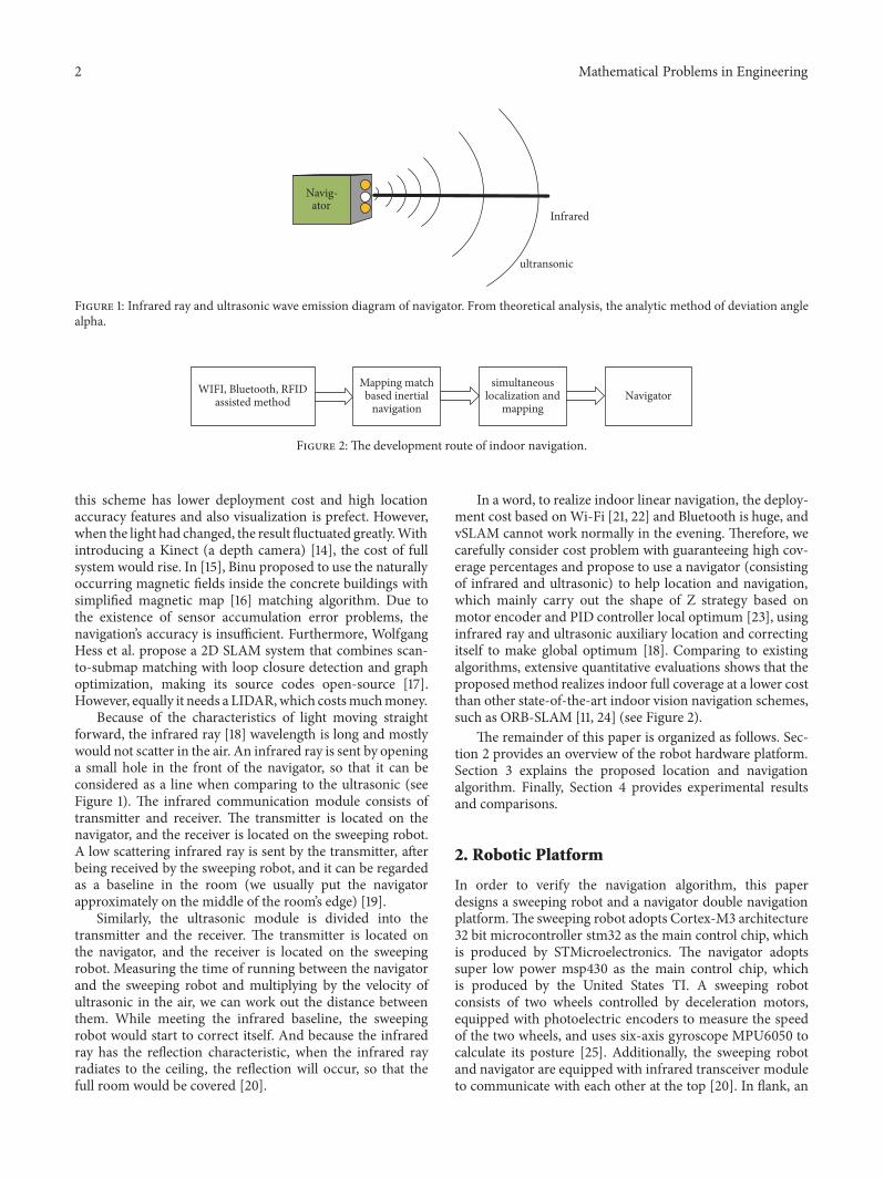
Figure 1 Infrared ray and ultrasonic wave emission diagram of navigator From theoretical analysis the analytic method of deviation anglealpha
WIFI Bluetooth RFIDassisted method
Mapping matchbased inertial
navigation
simultaneouslocalization and
mappingNavigator
Figure 2 The development route of indoor navigation
this scheme has lower deployment cost and high locationaccuracy features and also visualization is prefect Howeverwhen the light had changed the result fluctuated greatlyWithintroducing a Kinect (a depth camera) [14] the cost of fullsystem would rise In [15] Binu proposed to use the naturallyoccurring magnetic fields inside the concrete buildings withsimplified magnetic map [16] matching algorithm Due tothe existence of sensor accumulation error problems thenavigationrsquos accuracy is insufficient Furthermore WolfgangHess et al propose a 2D SLAM system that combines scan-to-submap matching with loop closure detection and graphoptimization making its source codes open-source [17]However equally it needs a LIDARwhich costsmuchmoney
Because of the characteristics of light moving straightforward the infrared ray [18] wavelength is long and mostlywould not scatter in the air An infrared ray is sent by openinga small hole in the front of the navigator so that it can beconsidered as a line when comparing to the ultrasonic (seeFigure 1) The infrared communication module consists oftransmitter and receiver The transmitter is located on thenavigator and the receiver is located on the sweeping robotA low scattering infrared ray is sent by the transmitter afterbeing received by the sweeping robot and it can be regardedas a baseline in the room (we usually put the navigatorapproximately on the middle of the roomrsquos edge) [19]
Similarly the ultrasonic module is divided into thetransmitter and the receiver The transmitter is located onthe navigator and the receiver is located on the sweepingrobot Measuring the time of running between the navigatorand the sweeping robot and multiplying by the velocity ofultrasonic in the air we can work out the distance betweenthem While meeting the infrared baseline the sweepingrobot would start to correct itself And because the infraredray has the reflection characteristic when the infrared rayradiates to the ceiling the reflection will occur so that thefull room would be covered [20]
In a word to realize indoor linear navigation the deploy-ment cost based onWi-Fi [21 22] and Bluetooth is huge andvSLAM cannot work normally in the evening Therefore wecarefully consider cost problem with guaranteeing high cov-erage percentages and propose to use a navigator (consistingof infrared and ultrasonic) to help location and navigationwhich mainly carry out the shape of Z strategy based onmotor encoder and PID controller local optimum [23] usinginfrared ray and ultrasonic auxiliary location and correctingitself to make global optimum [18] Comparing to existingalgorithms extensive quantitative evaluations shows that theproposed method realizes indoor full coverage at a lower costthan other state-of-the-art indoor vision navigation schemessuch as ORB-SLAM [11 24] (see Figure 2)
The remainder of this paper is organized as follows Sec-tion 2 provides an overview of the robot hardware platformSection 3 explains the proposed location and navigationalgorithm Finally Section 4 provides experimental resultsand comparisons
2 Robotic Platform
In order to verify the navigation algorithm this paperdesigns a sweeping robot and a navigator double navigationplatformThe sweeping robot adopts Cortex-M3 architecture32 bit microcontroller stm32 as the main control chip whichis produced by STMicroelectronics The navigator adoptssuper low power msp430 as the main control chip whichis produced by the United States TI A sweeping robotconsists of two wheels controlled by deceleration motorsequipped with photoelectric encoders to measure the speedof the two wheels and uses six-axis gyroscope MPU6050 tocalculate its posture [25] Additionally the sweeping robotand navigator are equipped with infrared transceiver moduleto communicate with each other at the top [20] In flank an
Mathematical Problems in Engineering 3
Navig-ator
SweepingRobot
③
④ ① ②
① ②
③
④
Motor IMU
① Infrared reception② Infrared transmission
③ Ultrasonic reception④ Ultrasonic transmission
Figure 3The infrared relies on ceiling reflection to cover full room communication
NavigatorSweeping
robot
ExpectPosition
RealPosition
rarra
rarrb
rarrc
Figure 4 From theoretical analysis the analytic method of deviation angle 120572
infrared sensor and ultrasonic sensor are used to obtain thedistance between them as shown in Figure 3
3 Location and Navigation of Indoor Robot
The navigator is located at the edge of the room and it regu-larly sends an infrared ray signals without scattering Whenthe sweeping robot detects infrared ray signal calculates thedistance 997888rarr119886 and records the wheels roll over the distance
997888rarr119887 the ultrasonic wave starts to emit regular frequency Withthe ultrasonic wave we could measure 997888rarr119888 again As a resultby solving 997888rarr119886 997888rarr119887 997888rarr119888 which form a vector triangle we canobtain the real forward angle and correct the sweeping robotdirection by comparison to the theoretical value as shown inFigure 4
31 Ensure Running in a Straight Line Traditionally asweeping robot can stably execute straight line because twowheels can keep themselves running with the same velocityBecause the electronic characteristics of two wheels may notbe completely consistent in the same PWM duty rate the
velocities of two motors are not exactly the same If there islong-term running the error is accumulated continually andthe sweeping robot would move forward one side Thereforeit is necessity to adjust the velocity of the two wheels in realtime so that the velocity of two wheels becomes the same androbot can keep itself linearly running for a long time withoutany consideration to the other obstacles
In this paper we installed two 26-hole photoelectrictachometer encoders at the back of the motors By measuringthe number of pulses 119873 generated by the photoelectricencoder in unit time 119879 and before that measuring thecircumference of the wheel L the formula is given as follows
119881 = (11987326) lowast 119871119879 (1)
Theoretically after obtaining the forward speed of V thevelocity of the wheel can be adjusted by the PID controlalgorithm in the field of classical automatic control Howeverconsidering the approximate errors produced on the formulatransformation we directly added the number of pulses Ngenerated by the photoelectric encoder to the PID formula
4 Mathematical Problems in Engineering
1Do2 if n=1 or 23 calculate the offsets of right and left wheel 119890
119877(119899)119890119871(119899)
4 calculate the current PWM value of right and left wheel 119906119877(119899) 119906
119871(119899)
5 substitute n=1 or 2 into equation(6) obtain 119906(1) 119906(2) 119890(1) 119890(2)6 if ngt=37 substitute 119906(119899 minus 1) 119890(119899) 119890(119899 minus 1)119890(119899 minus 2) into equation(6)8While (if work signal = true)9 return 119906(1)119906(2) 119890(1)119890(2) 119906(119899)
Algorithm 1 The implementation of PID algorithm
[26] instead of calculating the forward speed ofV eachwheelGenerally there are two kinds of PID as shown below
119906 (119899)= 119870119875119890 (119899) + 119879119879
119868
119899sum119894=0
119890 (119894) + 119879119863119879 [119890 (119899) minus 119890 (119899 minus 1)]
+ 1199060
(2)
Incremental PID control algorithm998779119906 (119899) = 119906 (119899) minus 119906 (119899 minus 1)
= 119870119875 [119890 (119899) minus 119890 (119899 minus 1)] + 119870
119875
119879119879119868
119890 (119899)+ 119870119875
119879119863119879 [119890 (119899) minus 2119890 (119899 minus 1) + 119890 (119899 minus 2)]
(3)
119890 (119899) = 119903 (119905) minus 119888 (119905) (4)
119888 (119905) = 119873 (5)where 119906(119899) is the output value of PID and 119903(119905) is
the desired value 119873 is the photoelectric encoder currentmeasurement value and 119890(119899) is the deviation value In thispaper DC motor is used for robotic motion by controllingthe duty rate of PWM to control the velocity so according tothe incremental PID control algorithm the recursion formulais
119906 (119899) = 119906 (119899 minus 1) + 998779119906 (119899)= 119906 (119899 minus 1) + 119870
119875(1 + 119879119879
119868
+ 119879119863119879 ) 119890 (119899)
minus 119870119875(1 + 2119879
119863119879 ) 119890 (119899 minus 1) minus 119870119875119890 (119899 minus 2)
= 119906 (119899 minus 1) + 1198870119890 (119899) + 119887
1119890 (119899 minus 1) + 119887
2119890 (119899 minus 2)
(6)
1198870= 119870119875(1 + 119879119879
119868
+ 119879119863119879 ) (7)
1198871= minus119870119875(1 + 2119879
119863119879 ) (8)
1198872= minus119870119875 (9)
where 119906(119899) is currently the value of PWM which suppliesmotor additionally 119906(119899 minus 1) is the last value of PWM 119890(119899)119890(119899minus1) 119890(119899minus2) are the offsets between expected velocity andreal velocity by current by last time and by the time beforelast time T is the sample time usually a fixed value119870
119875119879119868119879119863
are the parameters which will be optimized The algorithmrsquospseudocode is as in Algorithm 1
Among them 119906(1) 119906(2) 119890(1) 119890(2) are the PID outputvalues and offsets of the left and right wheel respectivelyUsing PID algorithm the mechanical errors can be elimi-nated and the robot can ensure that it is straight as much aspossible
32 Positioning and Navigation Algorithm
321 Angle and Position Correction The two wheels of thesweeping robot are driven by two independent motorsAlthough using PID regulation control can ensure that thetwo wheels are at the same speed the robot would shiftwhen running a distance because there may exist slipping andmechanical error A new method of angle and position cor-rection based on infrared and directional ultrasonic sensorsis presented in this paper as shown in Figure 5
The navigator is placed in the middle of the wall onone side of the room emitting vertical infrared ray and fan-shaped ultrasonic waves on both sides The angle of motionof the robot is always parallel to the wall When the robotruns from top to bottom and from right to left and each timeis in the middle of the room the robot receives infrared rayand ultrasonic waves determining its position by combiningonboard devices If the robot discovers deviation from thestraight line it corrects itself in time
Basic work principle With the infrared ray by thenavigator treated as the baseline we sent an ultrasonicwave with certain angles in particular frequency which canmeasure the precise position of robot Based on two times ofmeasurement we can resolve robotrsquos deviation angle Specificsteps are as follows (before the algorithm is detailed notethat we briefly define the notation that is used throughout thepaper in Table 1)
Step 1 When the robot arrives at the baseline of infrared afterit receives an infrared ray the distance 997888rarr119886 between them canbe obtained
Mathematical Problems in Engineering 5
navigator
robot
heading
t0
ti
tn
tj
t1
t2
t(j+1)
i lt j ti the current time
Figure 5 A diagram of the sweeping robot working Ti (i = 0 n)Table 1 The model of analytic geometry parameters
Symbol Description Symbol Description
O The position ofnavigator A The Expected
position of robotB The real position of robot
C The point where circle whose radius is equal to the distance of O to A cutsOB997888rarr119886 The vector of O to A |997888rarr119886 | The distance of O to A997888rarr119887 The vector of O to B |997888rarr119887 | The distance of O to B
997888rarr119888 The vector of A to B10038161003816100381610038161003816997888rarr119888 10038161003816100381610038161003816 The distance of A to B
997888rarr119889 The vector of O to C1003816100381610038161003816100381610038161003816997888rarr1198891003816100381610038161003816100381610038161003816 The distance of O to C997888rarr119890 The vector of A to C |997888rarr119890 | The distance of A to C
Step 2 After the robot leaves the baseline and runs in ashort distance |997888rarr119890 | measure the distance between them byultrasonic wave again
Step 3 Resolve the horizontal attitude angle 120572 from therelationship of geometry
120572 = arccos
10038161003816100381610038161003816997888rarr120572100381610038161003816100381610038162 + 10038161003816100381610038161003816997888rarr119890 100381610038161003816100381610038162 minus 1003816100381610038161003816100381610038161003816997888rarr11988910038161003816100381610038161003816100381610038162
2 10038161003816100381610038161003816997888rarr119890 10038161003816100381610038161003816 10038161003816100381610038161003816997888rarr119886 10038161003816100381610038161003816(10)
However as the complexity of the formula 120572 is expensiveand the gap between 997888rarr119890 and 997888rarr119886 is more than 103 orders ofmagnitude we propose a geometry algorithm to make thecomplexity reduction substantial (see Figure 6)
Follow 119874 as the center of a circle the direction of 997888rarr119886 as xaxis forward and the direction of perpendicular 997888rarr119886 as y axisforward Let down ⊙119874 trajectory is y=f(x) The slope of thetangent at C is 1198911015840(119888) in ⊙119874
The slope of AC because of |997888rarr119887 | towards 0 relative to 997888rarr119886 119909119862-119909119860=o(x) [27] o(x) is the infinitely small quantity of x
1198911015840 (119909119862) = lim119909119862997888rarr119909119860
119891 (119909119862) minus 119891 (119909119860)119909119862minus 119909119860
(11)
so the slope of the tangent at C being 1198911015840(119888) in ⊙O is equal tothe slope of AC
In the circle from the relationship of geometry997888rarr119889sdot
(11198911015840(119888))=0 then 997888rarr119889 sdot 997888rarr119890 =0Similarly 997888rarr119886 sdot 997888rarr119890 =0 from the relationship of geometry⟨minus997888rarr119886 997888rarr119888 ⟩=⟨minus997888rarr119886 997888rarr119890 ⟩+⟨minus997888rarr119890 997888rarr119888 ⟩
120572 = 90∘ + 120573 = 90∘ + arcsin
1003816100381610038161003816100381610038161003816997888rarr119887 1003816100381610038161003816100381610038161003816 minus 10038161003816100381610038161003816997888rarr119886 1003816100381610038161003816100381610038161003816100381610038161003816997888rarr119888 10038161003816100381610038161003816
(12)
As the (10) and (12) are antitrigonometric functions wecan directly consider the internal formula As we all know
6 Mathematical Problems in Engineering
rarra
rarrb
rarrc
rarrd
rarre
A
BC
O
y
x
Figure 6 Establishing coordinate system for the motion model of robot
appr
oxim
ated
angl
e err
or
radiusoffsets
minus3
5
45
4
35
3
25
2
15
1
05
01000 2000 3000 4000 5000 6000 7000 8000 9000 10000
times 10
Figure 7The relationship between radiusoffsets and approximate angle error
multiplication is nearly 10 times slower than addition andsubtraction and division is nearly 20 times slower thanaddition and subtraction when it is an 8-bit CPU Now wedefine the time of addition and subtraction as 119905 then themultiplication is 10119905 and division is 20119905 For (10) the timeof the whole equation is as follows
10119905 + 10119905 + 10119905 + 2119905 + 20119905 + 10119905 + 10119905 = 72119905 (13)
For equation (12) the time of the whole equation is as follows
119905 + 20119905 = 21119905 (14)
Then we have the following72119905 minus 2111990572119905 lowast 100 = 708 (15)
Compared with (10) (12) reduces the computationalcomplexity [28] and increases efficiency by nearly 708 Atthe same time it satisfies the actual precision requirementunder the condition of 119860119862 being smaller The relationshipbetween relative errors and deviation angle from the originalline is shown in Figure 7
322 Navigation Implementation between Multiple RoomsIn order to help a robot to cross different rooms to workcontinuously it should be improved autonomously In thispaper we built topology model for multiple rooms based onthe theory of graph optimization [29] Meanwhile the depth-first search (DFS) [30] stack is introduced to firstly select themost nearest and inmost room to work [31] which improvesthe efficiency of DFS The algorithmrsquos pseudocode is as inAlgorithm 2
In this algorithmwe define a room as119881119894(119894 = 1 119899) by the
navigator which has a unique encode signal We build a stackto store the room information so that the robot can selectthe most nearest and inmost room to work When it finishesthe current room then it checks the stack status every timeLastly it goes back to the initial room and stops working
4 Implementation and Experiments
We tested the SLMN algorithm in a 108 lowast 10m real indoorenvironment and the dimension of the robot was 08lowast 04mSince it is an upgraded TF card the robot could easily store
Mathematical Problems in Engineering 7
1Define every room has a unique ID 119881119894(119894 = 1 119899)
2 Let S be a stack3 if robot receive an infrared ray communication signals 119881
1
4 Start work in regular path5 if the robot receive another infrared ray communication signals 119881
2
6 Then Spush(1198812)
7 When finish working this room8 While S is not empty9 119881
119894= Spop()
10 Enter the ID of room 119881119894
11 if 119881119894is not labeled as discovered
12 Label 119881119894as discovered
13 Goto line 314 Back to initial room then the work is over15 Else16 Stop work
Algorithm 2 DFS stack for cleaning work
Figure 8 The model of a real robot
the data from the electronic motor encoder The real robotwas shown in Figure 8
After finishing its work run the local trajectory of therobot was restored (as the errors are small it is difficultto discover the trajectory of at a global view) as shown inFigure 9 The red and blue lines represent the robotrsquos truetrajectory and ideal trajectory respectively Therefore we canfind out that when the robot passed an infrared reference line(119910 = 5m) by the navigator the deviation trajectory would beeffectively corrected
By calculating the absolute value a good view of thisdeviation could be created The deviation that appears on[(5 + 104119896 5 + 104(119896 + 1)] will be effectively corrected at5 + 104(119896 + 1) as shown in Figure 10
Occasionally resources such as memory and computa-tional time are of primary concern but most often costand accuracy are what we want to measure By analyzingseveral candidate algorithms for the navigation problem [6]we can identify a most efficient one In this paper we putthe results of comparative analysis with other state-of-the-art algorithms such as vSLAM [11] LIDAR SLAM [17] andinertial navigation [32 33] as shown in Table 2
From Table 2 it is seen that the two SLAM systemshave similar precision which are the most highest However
their work time is also the shortest in the same batterycapacity so it needs more power to keep it working Althoughinertial navigation system has the lowest cost its error is tooenormous to work normally As a result our proposed algo-rithm has less energy cost in satisfying practical applicationscompared with other state-of-the-art algorithms
5 Conclusion
On the one hand this paper proposed a high efficiencymethod on indoor sweep robot line navigation The twomeasured values between navigator and robot and the dis-tance of robot motion can form a triangle then to solve theforward angle and correct the direction of forward speedwith analytic geometry principle Finally we implementedthe long time line navigation and based on that we proposemultiroom navigation algorithm After simulation and realityenvironment experiments on the threshold of error anindoor line navigation method based on the navigator whichconsists of the infrared and ultrasonic sensors even in theevening could resolve the problems on the other existingnavigation
On the other hand we prepare to do more works onbuilding a map based on the high efficiency motion to
8 Mathematical Problems in Engineering
Table 2 The result of performance test
Compared AlgorithmsPrecise and cost
Mean relative errors in 5001198982() Battery life with 12119881 (ℎ)1119860119867 3119860119867 5119860119867Proposed 673 17 49 76vSLAM 232 14 41 63Radar SLAM 317 13 39 59Inertial navigation 136 21 61 98
x (m)
y (m
)
12
10
8
6
4
2
0
minus2
minus2 minus1 0 1 2 3 4 5 6 7
Figure 9 The local trajectory of the robot had been restored a red line is the real trajectory of the robot and a blue line is the expectedtrajectory of the robot
05
045
04
035
03
025
02
015
01
005
00 10 20 30 40 50
x (m)
y (m
)
Figure 10 The variation trend of the deviation
improve its practicability and integrity so it can become self-charging and work continuously
Data Availability
The data used to support the findings of this study areavailable from the corresponding author upon request
Conflicts of Interest
The authors declare that they have no conflicts of interest
Acknowledgments
This work was supported by National Key RampD Programof China Nos 2018YFC0806900 2016YFC0800606 2016
Mathematical Problems in Engineering 9
YFC0800310 and 2018YFC0407905 Natural Science Foun-dation of Jiangsu Province under Grants Nos BK20150721and BK20161469 and Primary Research amp DevelopmentPlan of Jiangsu Province under Grants Nos BE2015728BE2016904 BE2017616 and BE2018754
References
[1] L Jia-jun Z Bi and H Yuan-lie ldquoResearch on Path PlanningAlgorithm for Cleaning Robot Based on Improved PotentialField Grid Methodrdquo Journal of Guangdong University of Tech-nology 2016
[2] J Shang X Hu F Gu D Wang and S Yu ldquoImprovementschemes for indoor mobile location estimation a surveyrdquoMathematical Problems in Engineering vol 2015 Article ID397298 32 pages 2015
[3] G Liu Y Geng and K Pahlavan ldquoEffects of calibration RFIDtags on performance of inertial navigation in indoor environ-mentrdquo in Proceedings of the 2015 International Conference onComputing Networking and Communications ICNC 2015 pp945ndash949 USA February 2015
[4] B-W Li and D-Y Yao ldquoLow-cost MEMS IMU navigationpositioning method for land vehiclerdquoZhongguo Guanxing JishuXuebaoJournal of Chinese Inertial Technology vol 22 no 6 pp719ndash723 2014
[5] S Lynen M W Achtelik S Weiss M Chli and R SiegwartldquoA robust and modular multi-sensor fusion approach appliedto MAV navigationrdquo in Proceedings of the 2013 26th IEEERSJInternational Conference on Intelligent Robots and Systems NewHorizon IROS 2013 pp 3923ndash3929 Japan November 2013
[6] Y Zheng G Shen L Li C Zhao M Li and F Zhao ldquoTravi-Navi self-deployable indoor navigation systemrdquo IEEEACMTransactions on Networking no 99 pp 1ndash15 2014
[7] J Rodas C J Escudero andD I Iglesia ldquoBayesian filtering for aBluetooth positioning systemrdquo in Proceedings of the 2008 IEEEInternational Symposium on Wireless Communication SystemsISWCSrsquo08 pp 618ndash622 Iceland October 2008
[8] P Lin Q Li Q Fan X Gao and S Hu ldquoA real-time location-based services system using WiFi fingerprinting algorithm forsafety risk assessment of workers in tunnelsrdquo MathematicalProblems in Engineering vol 2014 Article ID 371456 10 pages2014
[9] J Fuentes-Pacheco J Ruiz-Ascencio and J M Rendon-Mancha ldquoVisual simultaneous localization and mapping asurveyrdquo Artificial Intelligence Review vol 43 no 1 pp 55ndash812015
[10] S Leutenegger S Lynen M Bosse R Siegwart and P Fur-gale ldquoKeyframe-based visual-inertial odometry using nonlin-ear optimizationrdquo International Journal of Robotics Researchvol 34 no 3 pp 314ndash334 2015
[11] R Mur-Artal and J D Tardos ldquoORB-SLAM2 An Open-SourceSLAM System for Monocular Stereo and RGB-D CamerasrdquoIEEE Transactions on Robotics vol 33 no 5 pp 1255ndash1262 2017
[12] S Yin X Li H Gao and O Kaynak ldquoData-based techniquesfocused on modern industry an overviewrdquo IEEE Transactionson Industrial Electronics vol PP no 99 p 1 2014
[13] R A Newcombe S J Lovegrove and A J Davison ldquoDTAMDense tracking and mapping in real-timerdquo in Proceedings of the2011 IEEE International Conference on Computer Vision ICCV2011 pp 2320ndash2327 Spain November 2011
[14] J SmisekM Jancosek andT Pajdla ldquo3DwithKinect Advancesin Computer Vision Pattern Recognitionrdquo 3D with KinectAdvances in Computer Vision Pattern Recognition vol 21 no5 pp 1154ndash1160 2013
[15] P K Binu R A Krishnan and A P Kumar ldquoAn efficientindoor location tracking and navigation system using simplemagnetic map matchingrdquo in Proceedings of the 2016 IEEEInternational Conference on Computational Intelligence andComputing Research (ICCIC) pp 1ndash7 Chennai December 2016
[16] A Sud R Gayle E Andersen S Guy M Lin and D ManochaldquoReal-time navigation of independent agents using adaptiveroadmapsrdquo in Proceedings of the ACM SIGGRAPH 2008Classes2015
[17] W Hess D Kohler H Rapp and D Andor ldquoReal-time loopclosure in 2D LIDAR SLAMrdquo in Proceedings of the 2016 IEEEInternational Conference on Robotics and Automation ICRA2016 pp 1271ndash1278 Sweden May 2016
[18] K Wang T Song T Liang et al ldquoA dual-infrared-transmitteroptical wireless based indoor user localization systemwith highaccuracyrdquo in Proceedings of the 2017 Optical Fiber Communica-tions Conference and Exhibition OFC 2017 USA March 2017
[19] J Krejsa and S Vechet ldquoInfrared beacons based localization ofmobile robotrdquo Elektronika ir Elektrotechnika no 1 pp 17ndash222012
[20] J Yun andM-H Song ldquoDetecting direction ofmovement usingpyroelectric infrared sensorsrdquo IEEE Sensors Journal vol 14 no5 pp 1482ndash1489 2014
[21] D Han S Jung M Lee and G Yoon ldquoBuilding a practical wi-fi-based indoor navigation systemrdquo IEEE Pervasive Computingvol 13 no 2 pp 72ndash79 2014
[22] C Yang andH-R Shao ldquoWiFi-based indoor positioningrdquo IEEECommunications Magazine vol 53 no 3 pp 150ndash157 2015
[23] P Shah and S Agashe ldquoReview of fractional PID controllerrdquoMechatronics vol 38 pp 29ndash41 2016
[24] R Mur-Artal J M M Montiel and J D Tardos ldquoORB-SLAM a versatile and accuratemonocular SLAM systemrdquo IEEETransactions on Robotics vol 31 no 5 pp 1147ndash1163 2015
[25] J Simanek M Reinstein and V Kubelka ldquoEvaluation of theEKF-based estimation architectures for data fusion in mobilerobotsrdquo IEEEASME Transactions on Mechatronics vol 20 no2 pp 985ndash990 2015
[26] K J Astrom PID Controllers Theory Design and TuningInstrument Society ofAmerica ResearchTriangle ParkNc 1995
[27] A Banner ldquoThe Calculus Lifesaverrdquo 2009[28] T Hcormen C Eleiserson R Lrivest and C Stein Introduction
to Algorithms vol 39 Computer Education 3rd edition 2013[29] S R U MurtyGraph Theory with Applications North Holland
1976[30] K Mehlhorn ldquoEngineering DFS-based graph algorithmsrdquo 2017
httpsarxivorgabs171006055[31] R Tarjan ldquoDepth-first search and linear graph algorithmsrdquo in
Proceedings of the 12th Annual Symposium on Switching andAutomata Theory (swat 1971) pp 114ndash121 East Lansing MIUSA October 1971
[32] A R Jimenez F Seco J C Prieto and J Guevara ldquoIndoorPedestrian navigation using an INSEKF framework for yawdrift reduction and a foot-mounted IMUrdquo in Proceedings of the2010 7th Workshop on Positioning Navigation and Communica-tion WPNCrsquo10 pp 135ndash143 Germany March 2010
[33] B Barshan and H F Durrant-Whyte ldquoInertial navigationsystems for mobile robotsrdquo IEEE Transactions on Robotics andAutomation vol 11 no 3 pp 328ndash342 1998
Hindawiwwwhindawicom Volume 2018
MathematicsJournal of
Hindawiwwwhindawicom Volume 2018
Mathematical Problems in Engineering
Applied MathematicsJournal of
Hindawiwwwhindawicom Volume 2018
Probability and StatisticsHindawiwwwhindawicom Volume 2018
Journal of
Hindawiwwwhindawicom Volume 2018
Mathematical PhysicsAdvances in
Complex AnalysisJournal of
Hindawiwwwhindawicom Volume 2018
OptimizationJournal of
Hindawiwwwhindawicom Volume 2018
Hindawiwwwhindawicom Volume 2018
Engineering Mathematics
International Journal of
Hindawiwwwhindawicom Volume 2018
Operations ResearchAdvances in
Journal of
Hindawiwwwhindawicom Volume 2018
Function SpacesAbstract and Applied AnalysisHindawiwwwhindawicom Volume 2018
International Journal of Mathematics and Mathematical Sciences
Hindawiwwwhindawicom Volume 2018
Hindawi Publishing Corporation httpwwwhindawicom Volume 2013Hindawiwwwhindawicom
The Scientific World Journal
Volume 2018
Hindawiwwwhindawicom Volume 2018Volume 2018
Numerical AnalysisNumerical AnalysisNumerical AnalysisNumerical AnalysisNumerical AnalysisNumerical AnalysisNumerical AnalysisNumerical AnalysisNumerical AnalysisNumerical AnalysisNumerical AnalysisNumerical AnalysisAdvances inAdvances in Discrete Dynamics in
Nature and SocietyHindawiwwwhindawicom Volume 2018
Hindawiwwwhindawicom
Dierential EquationsInternational Journal of
Volume 2018
Hindawiwwwhindawicom Volume 2018
Decision SciencesAdvances in
Hindawiwwwhindawicom Volume 2018
AnalysisInternational Journal of
Hindawiwwwhindawicom Volume 2018
Stochastic AnalysisInternational Journal of
Submit your manuscripts atwwwhindawicom
2 Mathematical Problems in Engineering
Infrared
ultransonic
Navig-ator
Figure 1 Infrared ray and ultrasonic wave emission diagram of navigator From theoretical analysis the analytic method of deviation anglealpha
WIFI Bluetooth RFIDassisted method
Mapping matchbased inertial
navigation
simultaneouslocalization and
mappingNavigator
Figure 2 The development route of indoor navigation
this scheme has lower deployment cost and high locationaccuracy features and also visualization is prefect Howeverwhen the light had changed the result fluctuated greatlyWithintroducing a Kinect (a depth camera) [14] the cost of fullsystem would rise In [15] Binu proposed to use the naturallyoccurring magnetic fields inside the concrete buildings withsimplified magnetic map [16] matching algorithm Due tothe existence of sensor accumulation error problems thenavigationrsquos accuracy is insufficient Furthermore WolfgangHess et al propose a 2D SLAM system that combines scan-to-submap matching with loop closure detection and graphoptimization making its source codes open-source [17]However equally it needs a LIDARwhich costsmuchmoney
Because of the characteristics of light moving straightforward the infrared ray [18] wavelength is long and mostlywould not scatter in the air An infrared ray is sent by openinga small hole in the front of the navigator so that it can beconsidered as a line when comparing to the ultrasonic (seeFigure 1) The infrared communication module consists oftransmitter and receiver The transmitter is located on thenavigator and the receiver is located on the sweeping robotA low scattering infrared ray is sent by the transmitter afterbeing received by the sweeping robot and it can be regardedas a baseline in the room (we usually put the navigatorapproximately on the middle of the roomrsquos edge) [19]
Similarly the ultrasonic module is divided into thetransmitter and the receiver The transmitter is located onthe navigator and the receiver is located on the sweepingrobot Measuring the time of running between the navigatorand the sweeping robot and multiplying by the velocity ofultrasonic in the air we can work out the distance betweenthem While meeting the infrared baseline the sweepingrobot would start to correct itself And because the infraredray has the reflection characteristic when the infrared rayradiates to the ceiling the reflection will occur so that thefull room would be covered [20]
In a word to realize indoor linear navigation the deploy-ment cost based onWi-Fi [21 22] and Bluetooth is huge andvSLAM cannot work normally in the evening Therefore wecarefully consider cost problem with guaranteeing high cov-erage percentages and propose to use a navigator (consistingof infrared and ultrasonic) to help location and navigationwhich mainly carry out the shape of Z strategy based onmotor encoder and PID controller local optimum [23] usinginfrared ray and ultrasonic auxiliary location and correctingitself to make global optimum [18] Comparing to existingalgorithms extensive quantitative evaluations shows that theproposed method realizes indoor full coverage at a lower costthan other state-of-the-art indoor vision navigation schemessuch as ORB-SLAM [11 24] (see Figure 2)
The remainder of this paper is organized as follows Sec-tion 2 provides an overview of the robot hardware platformSection 3 explains the proposed location and navigationalgorithm Finally Section 4 provides experimental resultsand comparisons
2 Robotic Platform
In order to verify the navigation algorithm this paperdesigns a sweeping robot and a navigator double navigationplatformThe sweeping robot adopts Cortex-M3 architecture32 bit microcontroller stm32 as the main control chip whichis produced by STMicroelectronics The navigator adoptssuper low power msp430 as the main control chip whichis produced by the United States TI A sweeping robotconsists of two wheels controlled by deceleration motorsequipped with photoelectric encoders to measure the speedof the two wheels and uses six-axis gyroscope MPU6050 tocalculate its posture [25] Additionally the sweeping robotand navigator are equipped with infrared transceiver moduleto communicate with each other at the top [20] In flank an
Mathematical Problems in Engineering 3
Navig-ator
SweepingRobot
③
④ ① ②
① ②
③
④
Motor IMU
① Infrared reception② Infrared transmission
③ Ultrasonic reception④ Ultrasonic transmission
Figure 3The infrared relies on ceiling reflection to cover full room communication
NavigatorSweeping
robot
ExpectPosition
RealPosition
rarra
rarrb
rarrc
Figure 4 From theoretical analysis the analytic method of deviation angle 120572
infrared sensor and ultrasonic sensor are used to obtain thedistance between them as shown in Figure 3
3 Location and Navigation of Indoor Robot
The navigator is located at the edge of the room and it regu-larly sends an infrared ray signals without scattering Whenthe sweeping robot detects infrared ray signal calculates thedistance 997888rarr119886 and records the wheels roll over the distance
997888rarr119887 the ultrasonic wave starts to emit regular frequency Withthe ultrasonic wave we could measure 997888rarr119888 again As a resultby solving 997888rarr119886 997888rarr119887 997888rarr119888 which form a vector triangle we canobtain the real forward angle and correct the sweeping robotdirection by comparison to the theoretical value as shown inFigure 4
31 Ensure Running in a Straight Line Traditionally asweeping robot can stably execute straight line because twowheels can keep themselves running with the same velocityBecause the electronic characteristics of two wheels may notbe completely consistent in the same PWM duty rate the
velocities of two motors are not exactly the same If there islong-term running the error is accumulated continually andthe sweeping robot would move forward one side Thereforeit is necessity to adjust the velocity of the two wheels in realtime so that the velocity of two wheels becomes the same androbot can keep itself linearly running for a long time withoutany consideration to the other obstacles
In this paper we installed two 26-hole photoelectrictachometer encoders at the back of the motors By measuringthe number of pulses 119873 generated by the photoelectricencoder in unit time 119879 and before that measuring thecircumference of the wheel L the formula is given as follows
119881 = (11987326) lowast 119871119879 (1)
Theoretically after obtaining the forward speed of V thevelocity of the wheel can be adjusted by the PID controlalgorithm in the field of classical automatic control Howeverconsidering the approximate errors produced on the formulatransformation we directly added the number of pulses Ngenerated by the photoelectric encoder to the PID formula
4 Mathematical Problems in Engineering
1Do2 if n=1 or 23 calculate the offsets of right and left wheel 119890
119877(119899)119890119871(119899)
4 calculate the current PWM value of right and left wheel 119906119877(119899) 119906
119871(119899)
5 substitute n=1 or 2 into equation(6) obtain 119906(1) 119906(2) 119890(1) 119890(2)6 if ngt=37 substitute 119906(119899 minus 1) 119890(119899) 119890(119899 minus 1)119890(119899 minus 2) into equation(6)8While (if work signal = true)9 return 119906(1)119906(2) 119890(1)119890(2) 119906(119899)
Algorithm 1 The implementation of PID algorithm
[26] instead of calculating the forward speed ofV eachwheelGenerally there are two kinds of PID as shown below
119906 (119899)= 119870119875119890 (119899) + 119879119879
119868
119899sum119894=0
119890 (119894) + 119879119863119879 [119890 (119899) minus 119890 (119899 minus 1)]
+ 1199060
(2)
Incremental PID control algorithm998779119906 (119899) = 119906 (119899) minus 119906 (119899 minus 1)
= 119870119875 [119890 (119899) minus 119890 (119899 minus 1)] + 119870
119875
119879119879119868
119890 (119899)+ 119870119875
119879119863119879 [119890 (119899) minus 2119890 (119899 minus 1) + 119890 (119899 minus 2)]
(3)
119890 (119899) = 119903 (119905) minus 119888 (119905) (4)
119888 (119905) = 119873 (5)where 119906(119899) is the output value of PID and 119903(119905) is
the desired value 119873 is the photoelectric encoder currentmeasurement value and 119890(119899) is the deviation value In thispaper DC motor is used for robotic motion by controllingthe duty rate of PWM to control the velocity so according tothe incremental PID control algorithm the recursion formulais
119906 (119899) = 119906 (119899 minus 1) + 998779119906 (119899)= 119906 (119899 minus 1) + 119870
119875(1 + 119879119879
119868
+ 119879119863119879 ) 119890 (119899)
minus 119870119875(1 + 2119879
119863119879 ) 119890 (119899 minus 1) minus 119870119875119890 (119899 minus 2)
= 119906 (119899 minus 1) + 1198870119890 (119899) + 119887
1119890 (119899 minus 1) + 119887
2119890 (119899 minus 2)
(6)
1198870= 119870119875(1 + 119879119879
119868
+ 119879119863119879 ) (7)
1198871= minus119870119875(1 + 2119879
119863119879 ) (8)
1198872= minus119870119875 (9)
where 119906(119899) is currently the value of PWM which suppliesmotor additionally 119906(119899 minus 1) is the last value of PWM 119890(119899)119890(119899minus1) 119890(119899minus2) are the offsets between expected velocity andreal velocity by current by last time and by the time beforelast time T is the sample time usually a fixed value119870
119875119879119868119879119863
are the parameters which will be optimized The algorithmrsquospseudocode is as in Algorithm 1
Among them 119906(1) 119906(2) 119890(1) 119890(2) are the PID outputvalues and offsets of the left and right wheel respectivelyUsing PID algorithm the mechanical errors can be elimi-nated and the robot can ensure that it is straight as much aspossible
32 Positioning and Navigation Algorithm
321 Angle and Position Correction The two wheels of thesweeping robot are driven by two independent motorsAlthough using PID regulation control can ensure that thetwo wheels are at the same speed the robot would shiftwhen running a distance because there may exist slipping andmechanical error A new method of angle and position cor-rection based on infrared and directional ultrasonic sensorsis presented in this paper as shown in Figure 5
The navigator is placed in the middle of the wall onone side of the room emitting vertical infrared ray and fan-shaped ultrasonic waves on both sides The angle of motionof the robot is always parallel to the wall When the robotruns from top to bottom and from right to left and each timeis in the middle of the room the robot receives infrared rayand ultrasonic waves determining its position by combiningonboard devices If the robot discovers deviation from thestraight line it corrects itself in time
Basic work principle With the infrared ray by thenavigator treated as the baseline we sent an ultrasonicwave with certain angles in particular frequency which canmeasure the precise position of robot Based on two times ofmeasurement we can resolve robotrsquos deviation angle Specificsteps are as follows (before the algorithm is detailed notethat we briefly define the notation that is used throughout thepaper in Table 1)
Step 1 When the robot arrives at the baseline of infrared afterit receives an infrared ray the distance 997888rarr119886 between them canbe obtained
Mathematical Problems in Engineering 5
navigator
robot
heading
t0
ti
tn
tj
t1
t2
t(j+1)
i lt j ti the current time
Figure 5 A diagram of the sweeping robot working Ti (i = 0 n)Table 1 The model of analytic geometry parameters
Symbol Description Symbol Description
O The position ofnavigator A The Expected
position of robotB The real position of robot
C The point where circle whose radius is equal to the distance of O to A cutsOB997888rarr119886 The vector of O to A |997888rarr119886 | The distance of O to A997888rarr119887 The vector of O to B |997888rarr119887 | The distance of O to B
997888rarr119888 The vector of A to B10038161003816100381610038161003816997888rarr119888 10038161003816100381610038161003816 The distance of A to B
997888rarr119889 The vector of O to C1003816100381610038161003816100381610038161003816997888rarr1198891003816100381610038161003816100381610038161003816 The distance of O to C997888rarr119890 The vector of A to C |997888rarr119890 | The distance of A to C
Step 2 After the robot leaves the baseline and runs in ashort distance |997888rarr119890 | measure the distance between them byultrasonic wave again
Step 3 Resolve the horizontal attitude angle 120572 from therelationship of geometry
120572 = arccos
10038161003816100381610038161003816997888rarr120572100381610038161003816100381610038162 + 10038161003816100381610038161003816997888rarr119890 100381610038161003816100381610038162 minus 1003816100381610038161003816100381610038161003816997888rarr11988910038161003816100381610038161003816100381610038162
2 10038161003816100381610038161003816997888rarr119890 10038161003816100381610038161003816 10038161003816100381610038161003816997888rarr119886 10038161003816100381610038161003816(10)
However as the complexity of the formula 120572 is expensiveand the gap between 997888rarr119890 and 997888rarr119886 is more than 103 orders ofmagnitude we propose a geometry algorithm to make thecomplexity reduction substantial (see Figure 6)
Follow 119874 as the center of a circle the direction of 997888rarr119886 as xaxis forward and the direction of perpendicular 997888rarr119886 as y axisforward Let down ⊙119874 trajectory is y=f(x) The slope of thetangent at C is 1198911015840(119888) in ⊙119874
The slope of AC because of |997888rarr119887 | towards 0 relative to 997888rarr119886 119909119862-119909119860=o(x) [27] o(x) is the infinitely small quantity of x
1198911015840 (119909119862) = lim119909119862997888rarr119909119860
119891 (119909119862) minus 119891 (119909119860)119909119862minus 119909119860
(11)
so the slope of the tangent at C being 1198911015840(119888) in ⊙O is equal tothe slope of AC
In the circle from the relationship of geometry997888rarr119889sdot
(11198911015840(119888))=0 then 997888rarr119889 sdot 997888rarr119890 =0Similarly 997888rarr119886 sdot 997888rarr119890 =0 from the relationship of geometry⟨minus997888rarr119886 997888rarr119888 ⟩=⟨minus997888rarr119886 997888rarr119890 ⟩+⟨minus997888rarr119890 997888rarr119888 ⟩
120572 = 90∘ + 120573 = 90∘ + arcsin
1003816100381610038161003816100381610038161003816997888rarr119887 1003816100381610038161003816100381610038161003816 minus 10038161003816100381610038161003816997888rarr119886 1003816100381610038161003816100381610038161003816100381610038161003816997888rarr119888 10038161003816100381610038161003816
(12)
As the (10) and (12) are antitrigonometric functions wecan directly consider the internal formula As we all know
6 Mathematical Problems in Engineering
rarra
rarrb
rarrc
rarrd
rarre
A
BC
O
y
x
Figure 6 Establishing coordinate system for the motion model of robot
appr
oxim
ated
angl
e err
or
radiusoffsets
minus3
5
45
4
35
3
25
2
15
1
05
01000 2000 3000 4000 5000 6000 7000 8000 9000 10000
times 10
Figure 7The relationship between radiusoffsets and approximate angle error
multiplication is nearly 10 times slower than addition andsubtraction and division is nearly 20 times slower thanaddition and subtraction when it is an 8-bit CPU Now wedefine the time of addition and subtraction as 119905 then themultiplication is 10119905 and division is 20119905 For (10) the timeof the whole equation is as follows
10119905 + 10119905 + 10119905 + 2119905 + 20119905 + 10119905 + 10119905 = 72119905 (13)
For equation (12) the time of the whole equation is as follows
119905 + 20119905 = 21119905 (14)
Then we have the following72119905 minus 2111990572119905 lowast 100 = 708 (15)
Compared with (10) (12) reduces the computationalcomplexity [28] and increases efficiency by nearly 708 Atthe same time it satisfies the actual precision requirementunder the condition of 119860119862 being smaller The relationshipbetween relative errors and deviation angle from the originalline is shown in Figure 7
322 Navigation Implementation between Multiple RoomsIn order to help a robot to cross different rooms to workcontinuously it should be improved autonomously In thispaper we built topology model for multiple rooms based onthe theory of graph optimization [29] Meanwhile the depth-first search (DFS) [30] stack is introduced to firstly select themost nearest and inmost room to work [31] which improvesthe efficiency of DFS The algorithmrsquos pseudocode is as inAlgorithm 2
In this algorithmwe define a room as119881119894(119894 = 1 119899) by the
navigator which has a unique encode signal We build a stackto store the room information so that the robot can selectthe most nearest and inmost room to work When it finishesthe current room then it checks the stack status every timeLastly it goes back to the initial room and stops working
4 Implementation and Experiments
We tested the SLMN algorithm in a 108 lowast 10m real indoorenvironment and the dimension of the robot was 08lowast 04mSince it is an upgraded TF card the robot could easily store
Mathematical Problems in Engineering 7
1Define every room has a unique ID 119881119894(119894 = 1 119899)
2 Let S be a stack3 if robot receive an infrared ray communication signals 119881
1
4 Start work in regular path5 if the robot receive another infrared ray communication signals 119881
2
6 Then Spush(1198812)
7 When finish working this room8 While S is not empty9 119881
119894= Spop()
10 Enter the ID of room 119881119894
11 if 119881119894is not labeled as discovered
12 Label 119881119894as discovered
13 Goto line 314 Back to initial room then the work is over15 Else16 Stop work
Algorithm 2 DFS stack for cleaning work
Figure 8 The model of a real robot
the data from the electronic motor encoder The real robotwas shown in Figure 8
After finishing its work run the local trajectory of therobot was restored (as the errors are small it is difficultto discover the trajectory of at a global view) as shown inFigure 9 The red and blue lines represent the robotrsquos truetrajectory and ideal trajectory respectively Therefore we canfind out that when the robot passed an infrared reference line(119910 = 5m) by the navigator the deviation trajectory would beeffectively corrected
By calculating the absolute value a good view of thisdeviation could be created The deviation that appears on[(5 + 104119896 5 + 104(119896 + 1)] will be effectively corrected at5 + 104(119896 + 1) as shown in Figure 10
Occasionally resources such as memory and computa-tional time are of primary concern but most often costand accuracy are what we want to measure By analyzingseveral candidate algorithms for the navigation problem [6]we can identify a most efficient one In this paper we putthe results of comparative analysis with other state-of-the-art algorithms such as vSLAM [11] LIDAR SLAM [17] andinertial navigation [32 33] as shown in Table 2
From Table 2 it is seen that the two SLAM systemshave similar precision which are the most highest However
their work time is also the shortest in the same batterycapacity so it needs more power to keep it working Althoughinertial navigation system has the lowest cost its error is tooenormous to work normally As a result our proposed algo-rithm has less energy cost in satisfying practical applicationscompared with other state-of-the-art algorithms
5 Conclusion
On the one hand this paper proposed a high efficiencymethod on indoor sweep robot line navigation The twomeasured values between navigator and robot and the dis-tance of robot motion can form a triangle then to solve theforward angle and correct the direction of forward speedwith analytic geometry principle Finally we implementedthe long time line navigation and based on that we proposemultiroom navigation algorithm After simulation and realityenvironment experiments on the threshold of error anindoor line navigation method based on the navigator whichconsists of the infrared and ultrasonic sensors even in theevening could resolve the problems on the other existingnavigation
On the other hand we prepare to do more works onbuilding a map based on the high efficiency motion to
8 Mathematical Problems in Engineering
Table 2 The result of performance test
Compared AlgorithmsPrecise and cost
Mean relative errors in 5001198982() Battery life with 12119881 (ℎ)1119860119867 3119860119867 5119860119867Proposed 673 17 49 76vSLAM 232 14 41 63Radar SLAM 317 13 39 59Inertial navigation 136 21 61 98
x (m)
y (m
)
12
10
8
6
4
2
0
minus2
minus2 minus1 0 1 2 3 4 5 6 7
Figure 9 The local trajectory of the robot had been restored a red line is the real trajectory of the robot and a blue line is the expectedtrajectory of the robot
05
045
04
035
03
025
02
015
01
005
00 10 20 30 40 50
x (m)
y (m
)
Figure 10 The variation trend of the deviation
improve its practicability and integrity so it can become self-charging and work continuously
Data Availability
The data used to support the findings of this study areavailable from the corresponding author upon request
Conflicts of Interest
The authors declare that they have no conflicts of interest
Acknowledgments
This work was supported by National Key RampD Programof China Nos 2018YFC0806900 2016YFC0800606 2016
Mathematical Problems in Engineering 9
YFC0800310 and 2018YFC0407905 Natural Science Foun-dation of Jiangsu Province under Grants Nos BK20150721and BK20161469 and Primary Research amp DevelopmentPlan of Jiangsu Province under Grants Nos BE2015728BE2016904 BE2017616 and BE2018754
References
[1] L Jia-jun Z Bi and H Yuan-lie ldquoResearch on Path PlanningAlgorithm for Cleaning Robot Based on Improved PotentialField Grid Methodrdquo Journal of Guangdong University of Tech-nology 2016
[2] J Shang X Hu F Gu D Wang and S Yu ldquoImprovementschemes for indoor mobile location estimation a surveyrdquoMathematical Problems in Engineering vol 2015 Article ID397298 32 pages 2015
[3] G Liu Y Geng and K Pahlavan ldquoEffects of calibration RFIDtags on performance of inertial navigation in indoor environ-mentrdquo in Proceedings of the 2015 International Conference onComputing Networking and Communications ICNC 2015 pp945ndash949 USA February 2015
[4] B-W Li and D-Y Yao ldquoLow-cost MEMS IMU navigationpositioning method for land vehiclerdquoZhongguo Guanxing JishuXuebaoJournal of Chinese Inertial Technology vol 22 no 6 pp719ndash723 2014
[5] S Lynen M W Achtelik S Weiss M Chli and R SiegwartldquoA robust and modular multi-sensor fusion approach appliedto MAV navigationrdquo in Proceedings of the 2013 26th IEEERSJInternational Conference on Intelligent Robots and Systems NewHorizon IROS 2013 pp 3923ndash3929 Japan November 2013
[6] Y Zheng G Shen L Li C Zhao M Li and F Zhao ldquoTravi-Navi self-deployable indoor navigation systemrdquo IEEEACMTransactions on Networking no 99 pp 1ndash15 2014
[7] J Rodas C J Escudero andD I Iglesia ldquoBayesian filtering for aBluetooth positioning systemrdquo in Proceedings of the 2008 IEEEInternational Symposium on Wireless Communication SystemsISWCSrsquo08 pp 618ndash622 Iceland October 2008
[8] P Lin Q Li Q Fan X Gao and S Hu ldquoA real-time location-based services system using WiFi fingerprinting algorithm forsafety risk assessment of workers in tunnelsrdquo MathematicalProblems in Engineering vol 2014 Article ID 371456 10 pages2014
[9] J Fuentes-Pacheco J Ruiz-Ascencio and J M Rendon-Mancha ldquoVisual simultaneous localization and mapping asurveyrdquo Artificial Intelligence Review vol 43 no 1 pp 55ndash812015
[10] S Leutenegger S Lynen M Bosse R Siegwart and P Fur-gale ldquoKeyframe-based visual-inertial odometry using nonlin-ear optimizationrdquo International Journal of Robotics Researchvol 34 no 3 pp 314ndash334 2015
[11] R Mur-Artal and J D Tardos ldquoORB-SLAM2 An Open-SourceSLAM System for Monocular Stereo and RGB-D CamerasrdquoIEEE Transactions on Robotics vol 33 no 5 pp 1255ndash1262 2017
[12] S Yin X Li H Gao and O Kaynak ldquoData-based techniquesfocused on modern industry an overviewrdquo IEEE Transactionson Industrial Electronics vol PP no 99 p 1 2014
[13] R A Newcombe S J Lovegrove and A J Davison ldquoDTAMDense tracking and mapping in real-timerdquo in Proceedings of the2011 IEEE International Conference on Computer Vision ICCV2011 pp 2320ndash2327 Spain November 2011
[14] J SmisekM Jancosek andT Pajdla ldquo3DwithKinect Advancesin Computer Vision Pattern Recognitionrdquo 3D with KinectAdvances in Computer Vision Pattern Recognition vol 21 no5 pp 1154ndash1160 2013
[15] P K Binu R A Krishnan and A P Kumar ldquoAn efficientindoor location tracking and navigation system using simplemagnetic map matchingrdquo in Proceedings of the 2016 IEEEInternational Conference on Computational Intelligence andComputing Research (ICCIC) pp 1ndash7 Chennai December 2016
[16] A Sud R Gayle E Andersen S Guy M Lin and D ManochaldquoReal-time navigation of independent agents using adaptiveroadmapsrdquo in Proceedings of the ACM SIGGRAPH 2008Classes2015
[17] W Hess D Kohler H Rapp and D Andor ldquoReal-time loopclosure in 2D LIDAR SLAMrdquo in Proceedings of the 2016 IEEEInternational Conference on Robotics and Automation ICRA2016 pp 1271ndash1278 Sweden May 2016
[18] K Wang T Song T Liang et al ldquoA dual-infrared-transmitteroptical wireless based indoor user localization systemwith highaccuracyrdquo in Proceedings of the 2017 Optical Fiber Communica-tions Conference and Exhibition OFC 2017 USA March 2017
[19] J Krejsa and S Vechet ldquoInfrared beacons based localization ofmobile robotrdquo Elektronika ir Elektrotechnika no 1 pp 17ndash222012
[20] J Yun andM-H Song ldquoDetecting direction ofmovement usingpyroelectric infrared sensorsrdquo IEEE Sensors Journal vol 14 no5 pp 1482ndash1489 2014
[21] D Han S Jung M Lee and G Yoon ldquoBuilding a practical wi-fi-based indoor navigation systemrdquo IEEE Pervasive Computingvol 13 no 2 pp 72ndash79 2014
[22] C Yang andH-R Shao ldquoWiFi-based indoor positioningrdquo IEEECommunications Magazine vol 53 no 3 pp 150ndash157 2015
[23] P Shah and S Agashe ldquoReview of fractional PID controllerrdquoMechatronics vol 38 pp 29ndash41 2016
[24] R Mur-Artal J M M Montiel and J D Tardos ldquoORB-SLAM a versatile and accuratemonocular SLAM systemrdquo IEEETransactions on Robotics vol 31 no 5 pp 1147ndash1163 2015
[25] J Simanek M Reinstein and V Kubelka ldquoEvaluation of theEKF-based estimation architectures for data fusion in mobilerobotsrdquo IEEEASME Transactions on Mechatronics vol 20 no2 pp 985ndash990 2015
[26] K J Astrom PID Controllers Theory Design and TuningInstrument Society ofAmerica ResearchTriangle ParkNc 1995
[27] A Banner ldquoThe Calculus Lifesaverrdquo 2009[28] T Hcormen C Eleiserson R Lrivest and C Stein Introduction
to Algorithms vol 39 Computer Education 3rd edition 2013[29] S R U MurtyGraph Theory with Applications North Holland
1976[30] K Mehlhorn ldquoEngineering DFS-based graph algorithmsrdquo 2017
httpsarxivorgabs171006055[31] R Tarjan ldquoDepth-first search and linear graph algorithmsrdquo in
Proceedings of the 12th Annual Symposium on Switching andAutomata Theory (swat 1971) pp 114ndash121 East Lansing MIUSA October 1971
[32] A R Jimenez F Seco J C Prieto and J Guevara ldquoIndoorPedestrian navigation using an INSEKF framework for yawdrift reduction and a foot-mounted IMUrdquo in Proceedings of the2010 7th Workshop on Positioning Navigation and Communica-tion WPNCrsquo10 pp 135ndash143 Germany March 2010
[33] B Barshan and H F Durrant-Whyte ldquoInertial navigationsystems for mobile robotsrdquo IEEE Transactions on Robotics andAutomation vol 11 no 3 pp 328ndash342 1998
Hindawiwwwhindawicom Volume 2018
MathematicsJournal of
Hindawiwwwhindawicom Volume 2018
Mathematical Problems in Engineering
Applied MathematicsJournal of
Hindawiwwwhindawicom Volume 2018
Probability and StatisticsHindawiwwwhindawicom Volume 2018
Journal of
Hindawiwwwhindawicom Volume 2018
Mathematical PhysicsAdvances in
Complex AnalysisJournal of
Hindawiwwwhindawicom Volume 2018
OptimizationJournal of
Hindawiwwwhindawicom Volume 2018
Hindawiwwwhindawicom Volume 2018
Engineering Mathematics
International Journal of
Hindawiwwwhindawicom Volume 2018
Operations ResearchAdvances in
Journal of
Hindawiwwwhindawicom Volume 2018
Function SpacesAbstract and Applied AnalysisHindawiwwwhindawicom Volume 2018
International Journal of Mathematics and Mathematical Sciences
Hindawiwwwhindawicom Volume 2018
Hindawi Publishing Corporation httpwwwhindawicom Volume 2013Hindawiwwwhindawicom
The Scientific World Journal
Volume 2018
Hindawiwwwhindawicom Volume 2018Volume 2018
Numerical AnalysisNumerical AnalysisNumerical AnalysisNumerical AnalysisNumerical AnalysisNumerical AnalysisNumerical AnalysisNumerical AnalysisNumerical AnalysisNumerical AnalysisNumerical AnalysisNumerical AnalysisAdvances inAdvances in Discrete Dynamics in
Nature and SocietyHindawiwwwhindawicom Volume 2018
Hindawiwwwhindawicom
Dierential EquationsInternational Journal of
Volume 2018
Hindawiwwwhindawicom Volume 2018
Decision SciencesAdvances in
Hindawiwwwhindawicom Volume 2018
AnalysisInternational Journal of
Hindawiwwwhindawicom Volume 2018
Stochastic AnalysisInternational Journal of
Submit your manuscripts atwwwhindawicom
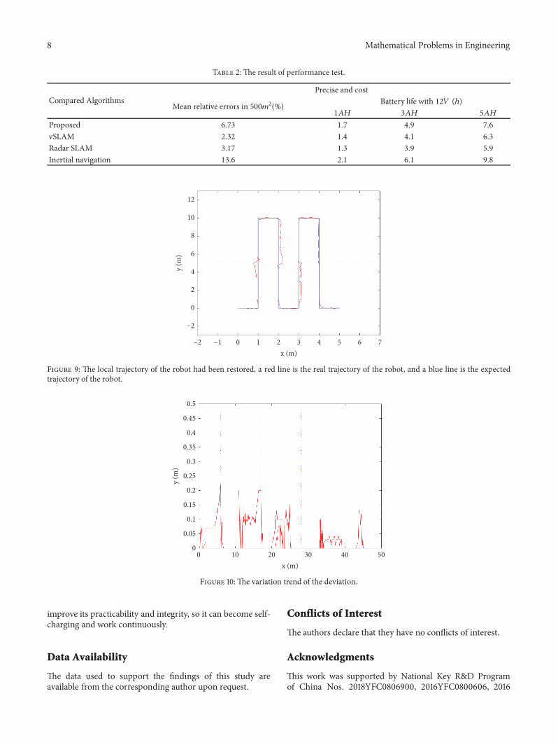

Hindawiwwwhindawicom Volume 2018
MathematicsJournal of
Hindawiwwwhindawicom Volume 2018
Mathematical Problems in Engineering
Applied MathematicsJournal of
Hindawiwwwhindawicom Volume 2018
Probability and StatisticsHindawiwwwhindawicom Volume 2018
Journal of
Hindawiwwwhindawicom Volume 2018
Mathematical PhysicsAdvances in
Complex AnalysisJournal of
Hindawiwwwhindawicom Volume 2018
OptimizationJournal of
Hindawiwwwhindawicom Volume 2018
Hindawiwwwhindawicom Volume 2018
Engineering Mathematics
International Journal of
Hindawiwwwhindawicom Volume 2018
Operations ResearchAdvances in
Journal of
Hindawiwwwhindawicom Volume 2018
Function SpacesAbstract and Applied AnalysisHindawiwwwhindawicom Volume 2018
International Journal of Mathematics and Mathematical Sciences
Hindawiwwwhindawicom Volume 2018
Hindawi Publishing Corporation httpwwwhindawicom Volume 2013Hindawiwwwhindawicom
The Scientific World Journal
Volume 2018
Hindawiwwwhindawicom Volume 2018Volume 2018
Numerical AnalysisNumerical AnalysisNumerical AnalysisNumerical AnalysisNumerical AnalysisNumerical AnalysisNumerical AnalysisNumerical AnalysisNumerical AnalysisNumerical AnalysisNumerical AnalysisNumerical AnalysisAdvances inAdvances in Discrete Dynamics in
Nature and SocietyHindawiwwwhindawicom Volume 2018
Hindawiwwwhindawicom
Dierential EquationsInternational Journal of
Volume 2018
Hindawiwwwhindawicom Volume 2018
Decision SciencesAdvances in
Hindawiwwwhindawicom Volume 2018
AnalysisInternational Journal of
Hindawiwwwhindawicom Volume 2018
Stochastic AnalysisInternational Journal of
Submit your manuscripts atwwwhindawicom