navigation simulator 13 - luizmonteiro.com · what you can do with the navigation simulator ......
TRANSCRIPT

Navigation Simulator
Version 1.12
Reference Manual
luizmonteiro.com
by Luiz Roberto Monteiro de Oliveira
2
Introduction ................................................................................................... 4
Note Regarding Use and Requirements .............................................................................................. 4 What you can do with the Navigation Simulator .................................................................................. 4
EULA (End User License Agreement) ......................................................... 6
Instrument Simulator Application ............................................................... 7
Simulator Versions ............................................................................................................................... 7 Parts Diagrams .................................................................................................................................... 8
Main Parts ............................................................................................................................... 8 Horizontal and Vertical Navigation Panels ............................................................................. 9 Additional Parts ..................................................................................................................... 10
Holding Pattern Template ........................................................................................ 11 Auxiliary / Reference Marks ..................................................................................... 11
Options Menus and Settings ................................................................................................ 12 Parts Description ............................................................................................................................... 13
Instruments ................................................................................................. 19
Analog Panel ..................................................................................................................................... 19 Attitude Indicator (AI) ............................................................................................................ 20 Airspeed Indicator (ASI) ....................................................................................................... 21 Altimeter (Alt) ........................................................................................................................ 22 Turn Coordinator (TC) .......................................................................................................... 23 Heading Indicator (HI)........................................................................................................... 24 Vertical Speed Indicator (VSI) .............................................................................................. 25 Horizontal Situation Indicator (HSI) ...................................................................................... 26 VOR 1 ................................................................................................................................... 27 VOR 2 ................................................................................................................................... 28 Radio Magnetic Indicator (RMI) ............................................................................................ 29 Automatic Direction Finder (ADF) ......................................................................................... 30 Main Instrument Panel Layout .............................................................................................. 31
Navaid and Instrument Association ................................................................................................... 32 Localizer and Glide Slope Simulation ................................................................................................ 33 Glass (Digital) Panel Layout .............................................................................................................. 36
Relative Positions Window ........................................................................ 37 Keyboard Control and Shortcuts .............................................................. 38
Aircraft Motion Control Panel ............................................................................................................. 38 Keyboard Layout Quick Reference .................................................................................................... 39 Keyboard Control Example ................................................................................................................ 40
Positioning Aircraft .................................................................................... 42
Positioning Aircraft Vertically and Horizontally .................................................................................. 42 Setting Aircraft Heading Manually ..................................................................................................... 44
Setting Aircraft Instruments and Knobs ................................................... 49
Analog Panel ..................................................................................................................................... 49
Table of Contents
www.luizmonteiro.com Tutorial Version 1.12

3
Setting the OBS and Other Knobs ........................................................................................ 49 Digital Panel ....................................................................................................................................... 52
Setting the CRS .................................................................................................................... 49 Setting the Altimeter ............................................................................................................. 53 Setting the Altitude Bug ........................................................................................................ 54 Setting the Heading Bug ....................................................................................................... 54 Setting the FMS Knob .......................................................................................................... 54 Other Ways to Set Knobs ..................................................................................................... 55 Setting the NAV Radios ........................................................................................................ 56 Soft Key Buttons ................................................................................................................... 57
Dual Panel View .......................................................................................... 58 Glossary of Terms ...................................................................................... 59
END
www.luizmonteiro.com Tutorial Version 1.12

4
Copyright 2008-2009 - Luiz Roberto Monteiro de Oliveira - LuizMonteiro LLC d/b/a - luizmonteiro.com - All rights reserved
www.luizmonteiro.com
Introduction
Thank you for using the Navigation Simulator from luizmonteiro.com. Please note that this tutorial is designed to help you learn how to use the simulator, however, it is not designed to teach you how to perform VOR, NDB, or ILS navigation. If you would like to know how to use these navigational aids there are several resources available, including the Instrument Flying Handbook published by the FAA (Federal Aviation Administration in the USA). At the time this tutorial was written an Adobe PDF version of the handbook could be
found at the following web site: http://www.faa.gov/library/manuals/aviation/ The simulator has been tested on Mac OSX, Windows XP, Windows Vista (32/64-bit), and Windows 7 (32/64-bit). However you must use the trial version to test the software before purchasing since memory, and computer speed among other factors determine if this software will work adequately on your computer.
Note Regarding Use and Requirements
Tutorial Version 1.12
Navigating by instruments is based on interpreting instruments that show the aircraft’s relationship to special radio stations whose positions are known. By practicing these skills the use of instruments becomes second nature and the pilot/navigator can be capable of handling more tasks and reduce training an actual aircraft. This simulator can be used by students and flight instructors to learn the basics of instrument navigation by “flying” a virtual aircraft and receiving feedback on what typical flight instruments display. The position of the aircraft and the navigational aids can also be manipulated by the user. This simulator focuses deliberately on the navigation part of flying, rather than the “feel” of the controls, and the person using the simulator plays the role of a navigator rather than the pilot. This allows the user to learn to navigate and concentrate on this task rather than divert his/her attention on keeping the aircraft on the desired course, bank angle, descent rate, etc. The control of the aircraft is done through keyboard input. Essentially the user, who is playing the role of the navigator, is telling the computer to bank the aircraft to a certain angle and maintain that, level the aircraft, or maintain a descent rate. The computer will do what would be required in terms of flight controls (yoke or stick, rudder pedals, throttle, flaps, etc.) to achieve this. This is the equivalent of asking the pilot of an aircraft to turn, stop the turn, level the aircraft, etc. The pilot will move the controls of the aircraft in order to achieve this, but you don’t have to worry about how the pilot does this. The “aircraft” that you are flying in the simulator is as generic as possible in order to simulate the widest spectrum and therefore has a very wide range of speed, turn, and climb/descent characteristics which in reality would be unrealistic if not impossible for a single aircraft to have.
Some of the maneuvers and procedures that can be learned using the software are: 1. VOR and NDB course intercepting and tracking
2. VOR and NDB holding patterns
3. DME holding patterns
4. Procedure turns
5. ILS localizer and glide slope intercepting and tracking
6. Intersection holding patterns including those based on VOR and VOR radials, NDB bearings and VOR radials, localizer and VOR radials or NDB bearings, with or without DME
7. DME arcs
8. Missed approach procedures
9. Other course reversal procedures
It can also be used as a tool to teach: 1. The effects of wind on:
a) Aircraft ground speed b) Climb and descent angle or path c) Course drift d) Determining the appropriate time and heading adjustments required in holding patterns
What you can do with the Navigation Simulator
Aircraft Motion Control Screen (controlled though keyboard)

5
Copyright 2008-2009 - Luiz Roberto Monteiro de Oliveira - LuizMonteiro LLC d/b/a - luizmonteiro.com - All rights reserved
www.luizmonteiro.com Tutorial Version 1.12
2. Off-course correction and intercept problems
3. Estimating time/distance to a VOR without using DME
4. Identifying intersections
5. Homing vs. tracking visualization
6. Correct interpretation of ADF, RMI, HSI and VOR/ILS
course indicators with the aircraft located in specific locations from the tuned nav radio source.
7. The effect of aircraft heading changes on ADF, RMI,
HSI and VOR/ILS display indications when tuned to a nav radio source.
8. The effect of course selection on the display of HSI and
VOR/ILS indicators when tuning VOR or ILS frequencies
6
Copyright 2008-2009 - Luiz Roberto Monteiro de Oliveira - LuizMonteiro LLC d/b/a - luizmonteiro.com - All rights reserved
www.luizmonteiro.com
EULA (End User License Agreement)
Tutorial Version 1.12
NO WARRANTY LUIZMONTEIRO.COM NAVIGATION SIMULATOR IS DISTRIBUTED "AS IS" AND WITHOUT ANY WARRANTY AS TO MERCHANTABILITY OR FITNESS FOR A PARTICULAR PURPOSE OR ANY OTHER WARRANTIES EITHER EXPRESSED OR IMPLIED. THE AUTHOR WILL NOT BE LIABLE FOR DATA LOSS, DAMAGES, LOSS OF PROFITS OR ANY OTHER KIND OF LOSS WHILE USING OR MISUSING THIS SOFTWARE. Any attempts at reverse-engineering or thwarting the license protection scheme of this software is prohibited. Any evidence of tampering will be investigated and may lead to prosecution according to all applicable laws. Distribution of the Evaluation Edition You may copy the Evaluation Edition of this software and documentation as you wish, and give exact copies of the original Evaluation Edition to anyone, and distribute the Evaluation Edition of the software and documentation in its unmodified form via electronic means. But you should not charge or request donations for any such copies however made, or from distributing the software and/or documentation with other products without the author's written permission. Trial License The trial license is available for the user to run the software and test it for a short period of time which may vary from version to version. Once the trial period has expired the user must remove the software from his/her computer or purchase a permanent license. The trial license is considered an opportunity for the user to test and to evaluate the software before purchase. Once purchased and registered it will be understood that the user accepts the software as it is and refunds will not be provided unless there are exceptional circumstances. Registered Edition A registered copy of LUIZMONTEIRO.COM NAVIGATION SIMULATOR may be used by the person that has registered the copy or by up to three people simultaneously, including the person who the copy is registered to provided that these people work in the same institution, company, or are being instructed by the owner of the registration, or are family members of the owner of the registration. Under these conditions the software may be installed and up to three computers.
If you purchased the license key you can enable the registered edition of the software. This code must be kept in the strictest confidence and must not be given or revealed to anyone but the registered owner. Installation files for licensed users also may not be distributed by you to anyone else. Failure to abide by these provisions may result in severe legal penalties and will result in revocation of the license. Other licensing options for classroom and for more than three users/computers is available by contacting [email protected]. Permanent License A registered license is a permanent license and entitles the holder to use the program forever - such license keys will never expire. The initial purchase price includes all program and updates of the same main version. For example version 1.0 will have free updates up to version 1.9. Version 2.0, 3.0 and so forth will be considered major revisions and may require an upgrade at a discount fee from the regular price, or the fee may be waived at the discretion of luizmonteiro.com.

7
There are two versions of the simulator depending on the screen resolution. The first one is for monitors that are at least 1280 x 1024 pixels. In this version the General Settings/Navaid Information tabs are always visible. The second version, which is more appropriate for smaller monitors and small widescreen monitors like those on laptops that have a lower than 1024 pixel height, is for screen resolutions of at least 1200 x 750 pixels. This version requires the General Settings/Navaid Information tabs to be toggled on and off by pressing the "O" key or through the options menu. Starting with the Navigation Simulator 1.11, you can resize the simulator to any size you like. Vector graphics help ensure quality at non-native resolutions. This allows the software to run in any monitor as long as the user can see the scaled graphics (if scaled down).
Copyright 2008-2009 - Luiz Roberto Monteiro de Oliveira - LuizMonteiro LLC d/b/a - luizmonteiro.com - All rights reserved
www.luizmonteiro.com
Instrument Simulator Application - Versions
Tutorial Version 1.12
1280 x 1024 pixels version
1200 x 750 pixels version

8
Copyright 2008-2009 - Luiz Roberto Monteiro de Oliveira - LuizMonteiro LLC d/b/a - luizmonteiro.com - All rights reserved
www.luizmonteiro.com
Instrument Simulator Application - Main Parts
Options Menu 1. General Settings 2. Navaid Information 3. Other Settings
Navaid/NAV settings
Horizontal Panel / Horizontal Navigation View
Vertical Panel / Vertical Navigation View
Tutorial Version 1.12
Main Instruments
Miscellaneous Info
Aircraft Motion Start / Pause Control
Aircraft Movement Control Display Aircraft Miscellaneous
Instruments
Menu Bar

9
Copyright 2008-2009 - Luiz Roberto Monteiro de Oliveira - LuizMonteiro LLC d/b/a - luizmonteiro.com - All rights reserved
www.luizmonteiro.com
Instrument Simulator Parts - Horizontal and Vertical Navigation Panels
Projection Flags
Projection Flags
To / From Legend
(Navaid 1)
Compass Rose Navaid 1
From Region Navaid 1
To Region Navaid 1
Aircraft Horizontal Symbol
Aircraft Vertical Symbol
Navigational Aid (Navaid)
Symbol
Navaid Number 1
Navaid Number 3
(NDB)
Navaid Number 2
Aircraft Radial from
Navaid 1
Wind Triangle
Aircraft Horizontal Path Trace
Aircraft Vertical Path Trace
Aircraft HDG / TAS
Vector
Wind Direction / Wind Speed Vector
Aircraft CRS / GS
Vector Map Scale
Intersection Symbol
Navaid 1 CRS Setting
From
Navaid 1 CRS Setting
To

10
Copyright 2008-2009 - Luiz Roberto Monteiro de Oliveira - LuizMonteiro LLC d/b/a - luizmonteiro.com - All rights reserved
www.luizmonteiro.com
Instrument Simulator Parts - Horizontal and Vertical Navigation Panels (continued)
Compass Rose Navaid 2
Additional Parts
Glide Slope Symbol
Navaid Number 3 Magnetic
North
Navaid 2 CRS Setting
From
Navaid 2 CRS Setting
To
Aircraft Radial from
Navaid 2
From Region Navaid 2
To Region Navaid 2
Aircraft Bearing from
Navaid 3
Aircraft Vertical Symbol
Intersection Symbol

11
Copyright 2008-2009 - Luiz Roberto Monteiro de Oliveira - LuizMonteiro LLC d/b/a - luizmonteiro.com - All rights reserved
www.luizmonteiro.com
Instrument Simulator Parts - Horizontal and Vertical Navigation Panels (continued)
Additional Parts
Relative Angle Depiction
Direct Sector
Holding Direction
Icon
Parallel Sector
Teardrop Sector
To / From Sector Bearing
Labels To / From
Sector Bearing Labels
Holding Pattern Template
Auxiliary / Reference Marks
Reference Line
Sector Division Line
Inbound CRS
Reference Line Direction Labels
Point of Reference for Reference Line
Aircraft Heading (HDG) or Track depending on option selected
Point of Reference for Relative Angle

12
Copyright 2008-2009 - Luiz Roberto Monteiro de Oliveira - LuizMonteiro LLC d/b/a - luizmonteiro.com - All rights reserved
www.luizmonteiro.com
Instrument Simulator Application - Options Menus and Settings
Tutorial Version 1.12
General Settings
Navaid / NAV settings
Navaid Information
Other Settings
13
Copyright 2008-2009 - Luiz Roberto Monteiro de Oliveira - LuizMonteiro LLC d/b/a - luizmonteiro.com - All rights reserved
www.luizmonteiro.com
Instrument Simulator Application Parts Description
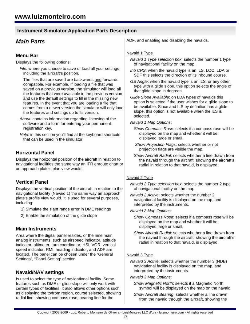
Main Parts
Menu Bar Displays the following options:
File: where you choose to save or load all your settings including the aircraft’s position.
The files that are saved are backwards and forwards compatible. For example, If loading a file that was saved on a previous version, the simulator will load all the features that were available in the previous version and use the default settings to fill in the missing new features. In the event that you are loading a file that comes from a newer version the simulator will only load the features and settings up to its version.
About: contains information regarding licensing of the software and a form for entering your permanent registration key.
Help: in this section you’ll find at the keyboard shortcuts that can be used in the simulator.
Horizontal Panel Displays the horizontal position of the aircraft in relation to navigational facilities the same way an IFR enroute chart or an approach plate's plan view would.
Vertical Panel Displays the vertical position of the aircraft in relation to the navigational facility (Navaid 1) the same way an approach plate's profile view would. It is used for several purposes, including:
1) Simulate the slant range error in DME readings
2) Enable the simulation of the glide slope
Main Instruments Area where the digital panel resides, or the nine main analog instruments, such as airspeed indicator, attitude indicator, altimeter, turn coordinator, HSI, VOR, vertical speed indicator, RMI, heading indicator, and ADF are located. The panel can be chosen under the “General Settings”, “Panel Setting” section.
Navaid/NAV settings Is used to select the type of navigational facility. Some features such as DME or glide slope will only work with certain types of facilities. It also allows other options such as displaying the to/from region, course selected, showing radial line, showing compass rose, bearing line for the
ADF, and enabling and disabling the navaids.
Navaid 1 Type
Navaid 1 Type selection box: selects the number 1 type of navigational facility on the map.
Inb CRS: when the navaid type is an ILS, LOC, LDA or SDF this selects the direction of its inbound course.
GS Angle: when the navaid type is an ILS, or any other type with a glide slope, this option selects the angle of that glide slope in degrees.
Glide Slope Available: on LDA types of navaids this option is selected if the user wishes for a glide slope to be available. Since and ILS by definition has a glide slope, this option is not available when the ILS is selected.
Navaid 1 Map Options:
Show Compass Rose: selects if a compass rose will be displayed on the map and whether it will be displayed large or small.
Show Projection Flags: selects whether or not projection flags are visible the map.
Show Aircraft Radial: selects whether a line drawn from the navaid through the aircraft, showing the aircraft’s radial in relation to that navaid, is displayed.
Navaid 2 Type
Navaid 2 Type selection box: selects the number 2 type of navigational facility on the map.
Navaid 2 Active: selects whether the number 2 navigational facility is displayed on the map, and interpreted by the instruments.
Navaid 2 Map Options:
Show Compass Rose: selects if a compass rose will be displayed on the map and whether it will be displayed large or small.
Show Aircraft Radial: selects whether a line drawn from the navaid through the aircraft, showing the aircraft’s radial in relation to that navaid, is displayed.
Navaid 3 Type
Navaid 3 Active: selects whether the number 3 (NDB) navigational facility is displayed on the map, and interpreted by the instruments.
Navaid 3 Map Options:
Show Magnetic North: selects if a Magnetic North symbol will be displayed on the map on the navaid.
Show Aircraft Bearing: selects whether a line drawn from the navaid through the aircraft, showing the

14
Copyright 2008-2009 - Luiz Roberto Monteiro de Oliveira - LuizMonteiro LLC d/b/a - luizmonteiro.com - All rights reserved
www.luizmonteiro.com
Instrument Simulator Application Parts Description (cont.)
aircraft’s bearing to that navaid, is displayed.
Intersection
Show Intersection: selects whether the intersection symbol is visible on the map.
Position Wizard: if the intersection symbol is visible, this button allows the user to position the intersection using a wizard.
Show Mag Direction Labels:
Radials/Bearings: selects whether text displaying the radial or bearing will be shown on the map when the Show Aircraft Radial or Show Bearing is selected.
OBS CRS: selects whether a text displaying the value of the OBS setting will be shown on the appropriate navaid when the OBS CRS To/Fr option is selected.
NAV 1 Visualization Aids:
Show To/from: selects whether the to and from area of the navaid tuned to NAV 1 will be shaded and displayed on the map.
Show OBS CRS To/Fr: when NAV 1 is tuned to a navaid other than an ILS, LOC, LDA or SDF this option selects whether a line will be drawn through the navaid showing the OBS CRS to and from that navaid. Otherwise a line will be drawn through the inbound course.
NAV 2 Visualization Aids:
Show To/from: selects whether the to and from area of the navaid tuned to NAV 2 will be shaded and displayed on the map.
Show OBS CRS To/Fr: when NAV 2 is tuned to a navaid other than an ILS, LOC, LDA or SDF this option selects whether a line will be drawn through the navaid showing the OBS CRS to and from that navaid. Otherwise a line will be drawn through the inbound course.
Miscellaneous Info Displays other information that although is not present or essential in the real aircraft it can be used to illustrate how climb angle is affected by ground speed, what is the exact track or course the aircraft is on, outside air pressure and other useful information.
Aircraft Motion - Start / Pause Control The start / pause button controls when movement begins or
pauses. Flight time and chronometer stop when aircraft motion stops. Aircraft circulating icon reinforces if aircraft is moving and what rate is the simulation speed. This control can also be activated through the keyboard shortcut ”P”. Aircraft Miscellaneous Instruments
Location for other instruments such as DME, flight time, and chronometer.
Aircraft Movement Control Display Area where indicated airspeed, bank angle, and climb / descent rates are shown. These are directly controlled by the keyboard commands.
General Settings Use this sections to select and activate different features.
Wind Triangle
Show Triangle: selects whether the wind triangle will be visible on the map.
Show Arrow: if show triangle is selected, this option will place arrows on the wind triangle vectors.
Size: sets the size of the wind triangle displayed on the map.
Label: selects whether labels will be drawn next to the wind triangle vectors showing the value for their direction and magnitude depending on options selected.
Wind
Spd: sets the value of the windspeed.
Dir: sets the value for the direction from where the wind is coming.
Trace Path
Trace On: when enabled, the path that the aircraft is taking will be recorded in memory. Please note that if you have a slower computer this might cause the simulator to significantly lose performance.
Show Trace: if the path of the aircraft was recorded or is being recorded through the “Trace On” option, a line will be drawn through the points that the aircraft traveled on the map.
Map Zoom
Zoom Out / in: changes the scale of the map so that features can be zoomed in or out. Note that if zooming in will cause the aircraft to lie outside of the map, the

15
Copyright 2008-2009 - Luiz Roberto Monteiro de Oliveira - LuizMonteiro LLC d/b/a - luizmonteiro.com - All rights reserved
www.luizmonteiro.com
Instrument Simulator Application Parts Description (cont.)
Zoom in button will not allow further zoom in.
Max Zoom In: selects the maximum zoom in scale.
Auto Zoom In: selects if zooming in is automatic when the aircraft is moving
Aircraft Motion Settings
Sim Speed: this option selects the timescale for the simulator. For example if 2x is selected time will pass twice as fast and the aircraft will appear to move twice as fast.
Max Bank: this selects the maximum banking limit when using the keyboard commands to bank. The default “Std Rate” automatically limits the bank to standard rate based on the aircraft’s current speed.
Global View
North Up: if selected, the map orientation will be north facing up. When deselected, the map orientation will be the aircraft’s heading facing up. Note that when “North Up” is NOT SELECTED additional computer processor performance will be necessary to keep moving the map as the aircraft heading changes. This can reduce the simulator’s performance. If you see that the simulator’s performance is slow it is best to keep the “North Up” option selected.
Show Map: when deselected, hides all of the features on the map. Use this mode to navigate on instruments alone and test your navigation skills.
Show Aircraft: when deselected, hides the aircraft icon on the map, along with aircraft specific map features.
Show Non-Essential: shows information such as aircraft CRS / TRK , ground speed, crab angle, climb angle, outside air temperature, outside air pressure. These may be nice to know items but are usually not available to pilots in their cockpit and are included in the simulator for teaching purposes.
Map Symbols: selects the size of aircraft and navigational aid icons on the map.
Declutter Map: removes all map features except for aircraft, navigational aids, and intersection symbol.
Altitude Range
Max Altitude: the maximum true altitude that the aircraft can go.
Min Altitude: the minimum altitude that the aircraft can go. This can be the airport altitude for example.
Alt Set: the value for the station’s or airport’s altimeter
setting. Not to be confused with the altimeter setting in the aircraft’s altimeter instrument.
Note: the three settings above require the “Enter Parameters” button to be pressed, once you’ve entered the values above, for settings to take effect.
Panel Setting
Drop-down menu: selects the type of instrument panel that will be displayed by the simulator.
Max IAS: maximum indicated airspeed. In the analog panel this setting also affects the scale of the airspeed indicator.
Show Magnetic Compass: determines whether or not the magnetic compass should be visible.
Latitude (deg): is used by the magnetic compass to simulate dip errors.
Performance
CPU Speed: for processors prior to Intel’s Core2 Duo or Core2 Quad it is recommended that this setting be left at “Slow”. For faster computers that setting will increase the smoothness of the map animation and the size of the aircraft’s traceable path.
NAV 1 and 2 “Radio”:
NAV 1 tuned to: selects which navigational aid on the map will be referenced by the aircraft’s NAV 1 instruments.
NAV 2 tuned to: selects which navigational aid on the map will be referenced by the aircraft’s NAV 2 instruments.
Memory
Load: retrieves all the settings and aircraft position from a memory slot.
Save: stores all the settings and aircraft position in a temporary memory slot.
Default: restores all default settings and default aircraft position.
Clr All: clears all the temporary memory slots.
Navaid Information Section Displays additional information regarding the instruments and aircraft positions relative to the navaids. It also includes a section with the complementary / analogous instruments. This displays the instruments that are not

16
Copyright 2008-2009 - Luiz Roberto Monteiro de Oliveira - LuizMonteiro LLC d/b/a - luizmonteiro.com - All rights reserved
www.luizmonteiro.com
Instrument Simulator Application Parts Description (cont.)
selected through the panel settings and can be used to compare these instruments with their complementary or analogous counterparts displayed in the main instruments area. The analogous instruments will only be visible when an analog panel is selected.
Other Settings Section In this section you will find settings for:
Holding Pattern Template
Show Template: selects whether or not the “Holding Pattern Template” will be visible on the map.
Non Standard (left turns): if enabled, the holding template will be shown for left turn holding patterns. If disabled, the standard right holding pattern turns will be depicted.
Relative to: selects if the holding pattern template will be relative to a particular navaid or intersection.
Inbound Course: the course in degrees for the holding pattern’s inbound course.
View:
Sector Direction Labels: shows labels in degrees both outbound and inbound for each sector.
Sector Division Lines: draws the line at the division of each sector.
Inbound CRS: draws a line and arrow in the direction of the inbound course.
Course Abeam Lines: draws two lines abeam the inbound course.
Holding Symbol: shows a race track pattern symbol that depicts the direction of turns for the holding pattern. Note that this symbol is not drawn to scale and should only be used to determine the direction of turns for the holding pattern.
Auxiliary / Reference Marks
Show Reference Line: selects whether or not the Reference Line will be visible on the map.
Relative to: selects if the reference line template will be relative to a particular navaid or intersection.
Ref Line Course: selects the direction that the reference line will be drawn. “Recip” button changes that value in 180°.
Ref on Outbound Course: selects if the line will be drawn from, or outbound of, the reference point.
Ref on Inbound Course: selects if the line will be drawn to, or inbound of, the reference point.
Ref on Both: selects whether the line will be drawn both inbound and outbound of the reference point.
Show Ref Line Labels: if selected displays labels for the direction in degrees of the course of the reference line.
Show Angle Relative to Acft:
Relative to Heading: draws a line from the aircraft in the direction of its heading. If that line intersects the reference line an angle symbol and a label displaying the relative angle in degrees between the two lines will be displayed.
Relative to Acft Track: draws a line from the aircraft in the direction of its track. If that line intersects the reference line an angle symbol and a label displaying the relative angle in degrees between the two lines will be displayed.
Relative to Rad: draws a line from the Navaid to the aircraft and displays an angle between that line and the reference line. Additionally a label showing the value for the radial in degrees relative to the aircraft position is drawn.
Relative to Brg: draws a line from the aircraft to the Navaid and display the angle between that line and the reference line. Additionally a label with the bearing from the aircraft to the navaid in degrees is drawn.
Show Angle Forward of Point: determines if the angle displayed between the reference line and the second line is drawn before or after the point that they intersect.
Aircraft Random Position
Rad / Brg: the computer will pick a random angle from the reference point. This angle will be between the specified Min and Max values inputted by the user. For example: (1) if Min=25 and Max=90 the computer will pick an angle between 25 and 90. (2) if Min=280 and Max=70, the computer will pick angles between 280 and 360 and 0 to 70. Notice that in example 2 if the Min angle is greater than the Max angle the computer will pick values clockwise from the Min angle to 360 then from 0 to the Max angle.
Distance: the computer will pick a random value for the distance that the aircraft will be positioned from the reference point.
Relative to: selects if the reference point that the previous settings are relative to.
Randomly Place Aircraft: once the range of values have been picked, pressing this button will position the aircraft randomly. This button can be pressed multiple times if desired.
Aircraft Random Heading
Rad / Brg: the computer will pick a random HDG. This

17
Copyright 2008-2009 - Luiz Roberto Monteiro de Oliveira - LuizMonteiro LLC d/b/a - luizmonteiro.com - All rights reserved
www.luizmonteiro.com
Instrument Simulator Application Parts Description (cont.)
value will be between the specified Min and Max values inputted by the user. For example: (1) if Min=25 and Max=90 the computer will pick an angle between 25 and 90. (2) if Min=280 and Max=70, the computer will pick HDG values between 280 and 360 and 0 to 70. Notice that in example 2 if the Min HDG is greater than the Max HDG the computer will pick values clockwise from the Min angle to 360 then from 0 to the Max HDG.
Position Wizards
Use these position wizards to place a navaid, aircraft or intersection in a precise location based on options and settings that you select.
Attitude Indicator
Show pitch up / down when climbing / descending: when this option is selected the aircraft will pitch up or down proportionally to its ascent or descent angle. By default this option is turned off (see attitude indicator for details).
ILS / LOC DME Offset:
In many approaches with glide slope, the DME transmitter does not coincide with the glide slope transmitter. Use this option to set the distance that the DME transmitter is from the glide slope transmitter. The value is negative if the DME transmitter is before the glide slope, and the value is positive if it is after the glide slope. This option is useful if you are trying to replicate an existing approach plate.
Additional Parts Description
Navigational Aid Symbol Represents the Navigational Aid selected and is similar to the representation found on aeronautical charts.
Intersection Symbol Represents a position that can be used as a reference by the user when navigating. This intersection is a reference only and is not used by the instruments. However it can be set in a position that is relative to the navaids and then, indirectly, it can be used for navigation.
From Region Shows on the Horizontal Navigation panel the region where the VOR / HSI flag will display From if the aircraft is positioned in the From region regardless of heading.
To Region Shows on the Horizontal Navigation panel the region where the VOR / HSI flag will display To if the aircraft is positioned in the To region regardless of heading.
Aircraft Horizontal / Vertical Path Trace Displays the path that the aircraft has flown.
Aircraft Horizontal / Vertical Symbol Used to show aircraft's horizontal / vertical position in relation to the navigational facility (navaid).
Wind Triangle Shows the vectors that make up the wind triangle. It shows the green (heading and true airspeed) plus the blue (wind direction and wind speed) resulting in the orange (course and ground speed) vectors.
Aircraft Radial Line A brown line showing the radial that the aircraft is on in relation to the navaid.
Projection Flags IFR approach plates have a profile view that displays the sideways vertical projection of the approach course. The projection flags serve to help visualize how and where this projection is made from the Horizontal Panel view. Notice how the aircraft moves on the Horizontal panel when it is dragged on the Vertical panel and vice versa. The movement is made in alignment with the projection flags. The projection is made in relation to navaid 1 only.
Compass Rose Used as an aid to show the orientation of the Horizontal Navigation panel. It serves the same purpose as the compass rose symbol on IFR enroute charts to show direction in relation to the magnetic north.
Magnetic North Symbol Similar to the compass rose in that it is used to indicate the direction of the magnetic North. In this case it is the symbol on the NDB (navaid 3).
Course (CRS) Setting From / To Line Shows a line passing through the navaid in the direction of
18
Copyright 2008-2009 - Luiz Roberto Monteiro de Oliveira - LuizMonteiro LLC d/b/a - luizmonteiro.com - All rights reserved
www.luizmonteiro.com
Instrument Simulator Application Parts Description (cont.)
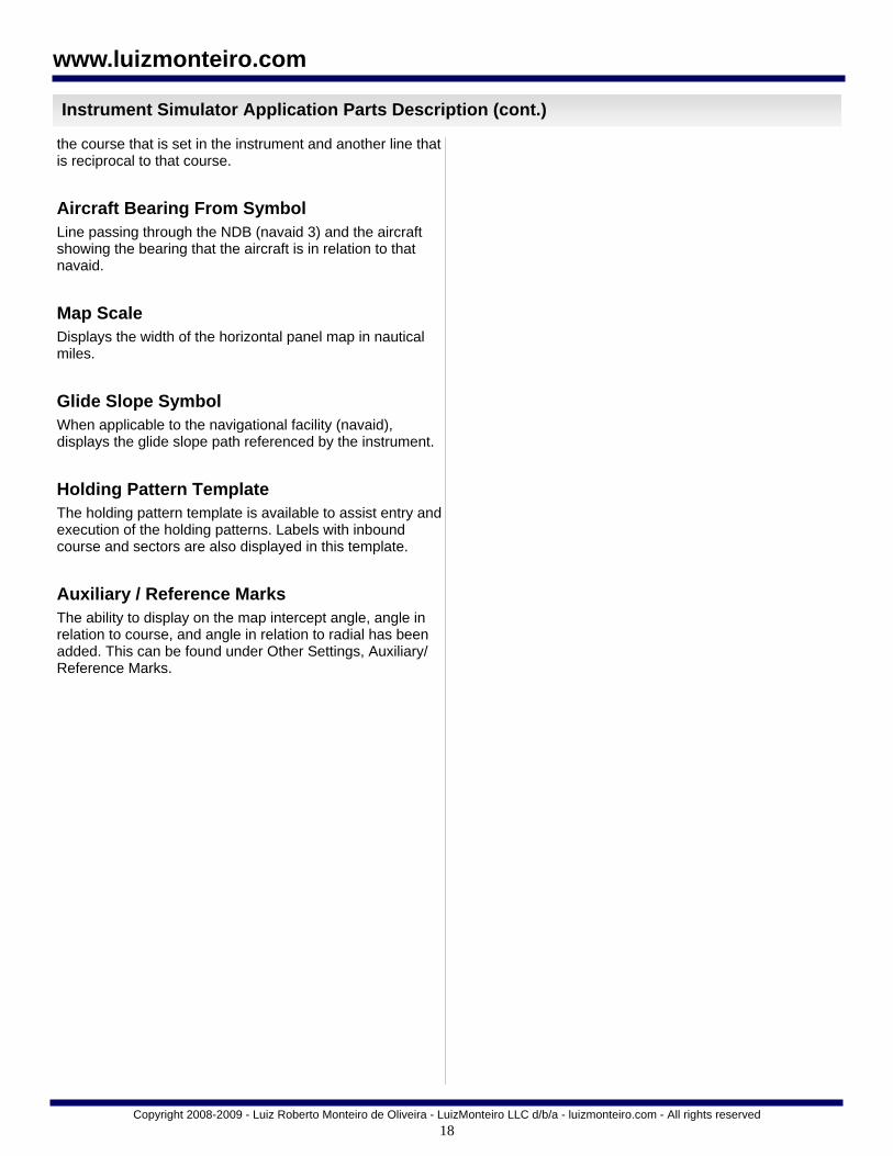
the course that is set in the instrument and another line that is reciprocal to that course.
Aircraft Bearing From Symbol Line passing through the NDB (navaid 3) and the aircraft showing the bearing that the aircraft is in relation to that navaid.
Map Scale Displays the width of the horizontal panel map in nautical miles.
Glide Slope Symbol When applicable to the navigational facility (navaid), displays the glide slope path referenced by the instrument.
Holding Pattern Template The holding pattern template is available to assist entry and execution of the holding patterns. Labels with inbound course and sectors are also displayed in this template.
Auxiliary / Reference Marks The ability to display on the map intercept angle, angle in relation to course, and angle in relation to radial has been added. This can be found under Other Settings, Auxiliary/Reference Marks.

19
Copyright 2008-2009 - Luiz Roberto Monteiro de Oliveira - LuizMonteiro LLC d/b/a - luizmonteiro.com - All rights reserved
www.luizmonteiro.com
Instrument Simulator Parts - Instrument Layout (Analog Panel)
Main instrument panel
Vertical Speed Indicator (VSI)
Altimeter (ALT)
VOR 2 Instrument
Magnetic Compass (MC)
Attitude Indicator (AI) Airspeed Indicator (ASI)
VOR 1 / Glide slope Instrument
Turn Coordinator (TC)
Heading Indicator (HI)
Radio Magnetic Indicator (RMI)
Chronometer Flight Time
Distance Measuring Equipment (DME)
Horizontal Situation Indicator (HIS)
Automatic Direction Finder (ADF)

20
The attitude indicator (AI) shows the bank and pitch of the aircraft. In this simulator it is used primarily to show the bank angle that is required to achieve a certain rate of turn. In a stable turn the bank angle is dependent on the speed and rate of turn. The greater the airspeed and rate of turn, the greater the bank angle required. In an actual aircraft it is possible to have a different pitch for the same exact climb or descent angle. This depends on many different factors including the type of aircraft, how much power thrust, lift, and other factors. Typically in instrument flying there are only slight variations in pitch. In order to simulate a very wide range of aircraft in this program, the pitch is left at zero unless the aircraft is in a steep bank and in that case the pitch goes up slightly as it would be necessary to compensate for the load factor. In other words, except when banking, the pitch is kept level as a default option even when the aircraft is climbing or
descending. To illustrate why this simplification is made, below are several different aircraft at varying speeds and climb or descent rates. Despite this all of them can be flying at a zero pitch attitude. It is important to stress that when actually flying an aircraft, pitch will be extremely important and should not be disregarded. However since the simulator is very generic there is little sense in simulating pitch display on the attitude indicator for the purposes of learning navigation. It is possible (version 1.12 up) to enable pitch display when the aircraft descends or ascends by checking the option in the “Attitude Indicator” section in the “Other Settings Tab”.
Copyright 2008-2009 - Luiz Roberto Monteiro de Oliveira - LuizMonteiro LLC d/b/a - luizmonteiro.com - All rights reserved
www.luizmonteiro.com
Important Note
Attitude indicator (AI)
With the arrow representing a stabilized direction of flight, all these aircraft are flying at zero pitch attitude
Attitude Indicator (Analog)
Pitch is increased when banking
Enabling pitch indication box

21
The airspeed indicator (ASI) displays the aircraft’s approximate airspeed in relation to the air according to the pressure differential sensed by the pitot static system of the aircraft. Typically this instrument does not display a Mach reading however in this simulator it has been added as a nice to know feature. It is important to note that the true airspeed (TAS) which is the actual speed that the aircraft is moving in relation to the air, as a general rule, increases in relation to the indicated airspeed (IAS) as the air gets thinner (less dense) and the altitude increases. The airspeed indicator is calibrated so that it would show true airspeed at sea level under standard atmospheric conditions. A pilot usually applies the necessary power and flight controls in order to maintain an indicated airspeed, therefore this is
the speed that is controlled through the keyboard (please refer to the section on keyboard control) in this simulator. The indicated airspeed is also the airspeed that is referred by air traffic controllers when they ask to maintain a certain airspeed. It is also the speed referred to for speed limitations and holding patterns and certain types of airspace. Several ranges of aircraft speed can be selected in this simulator. The airspeed indicator instrument will have the appropriate scale. Please see below the different airspeed indicators, each having a different scale.
Copyright 2008-2009 - Luiz Roberto Monteiro de Oliveira - LuizMonteiro LLC d/b/a - luizmonteiro.com - All rights reserved
www.luizmonteiro.com
Instrument Simulator Parts - Instruments
Airspeed Indicator (Analog)
Speed range selected through the options menu
Several airspeed indicators with different scales
airspeed indicator (ASI)

22
The altimeter (Alt) indicates the approximate altitude of the aircraft sensed by the aircraft’s static port. Since this instrument is basically a barometer calibrated to show the aircraft’s altitude in standard atmosphere, it is not accurate when flying in different conditions (non-standard). The altimeter setting, which the pilot can set on the altimeter’s Kollsman window, allows the instrument to
somewhat compensate for some of these errors. However the altimeter will still only show the correct altitude when flying at the altitude where the station that the altimeter setting was taken is located. In other words when the pilot gets the altimeter setting for the airport that he/she is at, the altimeter will only be accurate at the altitude of that airport unless the pressure and temperature conditions are that of standard atmosphere. The default altimeter setting is set at 29.92 inches of mercury. However, it can be changed by the user using the knob on the instrument.
Copyright 2008-2009 - Luiz Roberto Monteiro de Oliveira - LuizMonteiro LLC d/b/a - luizmonteiro.com - All rights reserved
www.luizmonteiro.com
Navigation Simulator Parts - Instruments
Altimeter (Alt)
Parts of the altimeter
Altimeter (Analog)
Ten thousands of feet needle
hundreds of feet needle
thousands of feet needle
This striped flag starts showing when the altitude on the altimeter is less than 15,000 feet and is
completely shown when below 10,000 feet (this may very depending on the altimeter on actual aircraft)
Kollsman Window
Knob used to Set Kollsman
Window
23
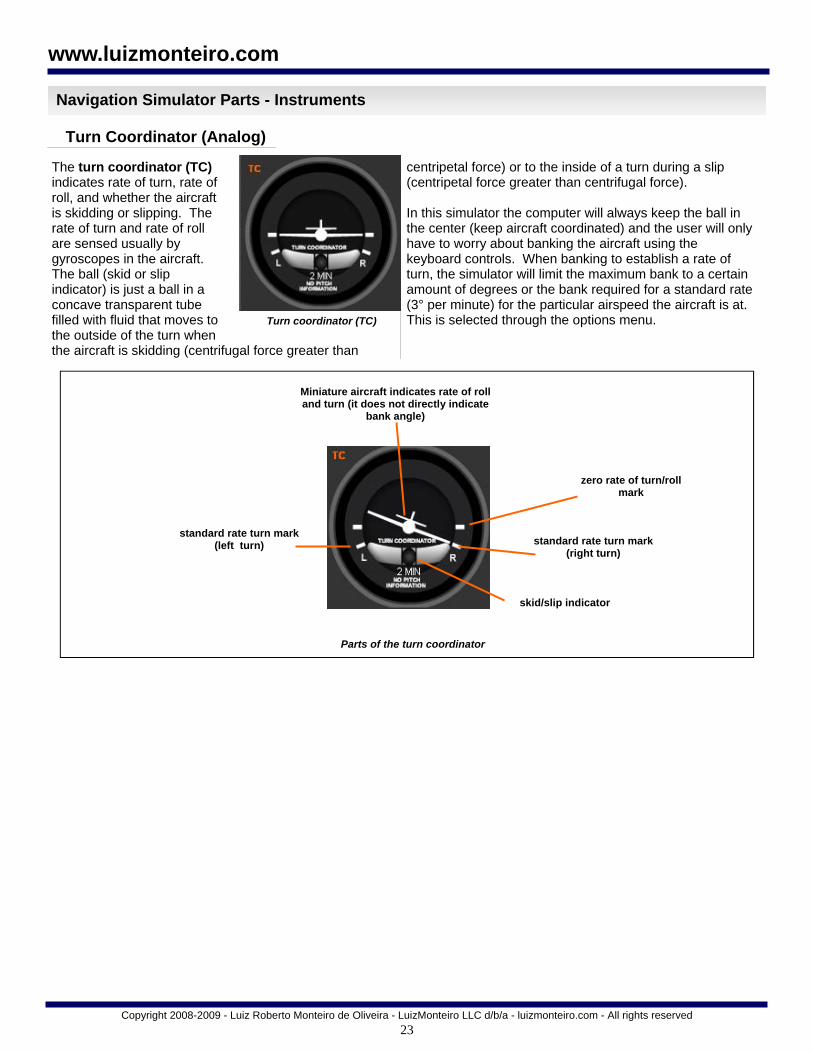
The turn coordinator (TC) indicates rate of turn, rate of roll, and whether the aircraft is skidding or slipping. The rate of turn and rate of roll are sensed usually by gyroscopes in the aircraft. The ball (skid or slip indicator) is just a ball in a concave transparent tube filled with fluid that moves to the outside of the turn when the aircraft is skidding (centrifugal force greater than
centripetal force) or to the inside of a turn during a slip (centripetal force greater than centrifugal force). In this simulator the computer will always keep the ball in the center (keep aircraft coordinated) and the user will only have to worry about banking the aircraft using the keyboard controls. When banking to establish a rate of turn, the simulator will limit the maximum bank to a certain amount of degrees or the bank required for a standard rate (3° per minute) for the particular airspeed the aircraft is at. This is selected through the options menu.
Copyright 2008-2009 - Luiz Roberto Monteiro de Oliveira - LuizMonteiro LLC d/b/a - luizmonteiro.com - All rights reserved
www.luizmonteiro.com
Navigation Simulator Parts - Instruments
Turn coordinator (TC)
Parts of the turn coordinator
Turn Coordinator (Analog)
Miniature aircraft indicates rate of roll and turn (it does not directly indicate
bank angle)
standard rate turn mark (left turn)
skid/slip indicator
zero rate of turn/roll mark
standard rate turn mark (right turn)

24
The heading indicator (HI) displays the heading of an aircraft. It works with a gyroscope that stays rigid while the aircraft turns. The pilot usually has to keep re-adjusting this instrument to the compass approximately every 15 minutes since it has a tendency to drift due to gyroscopic precession. In this simulator it is kept aligned and there is no need to
worry about setting it so that the user can concentrate on navigation. There is also a red heading bug that can be used to remind the pilot of certain headings.
Copyright 2008-2009 - Luiz Roberto Monteiro de Oliveira - LuizMonteiro LLC d/b/a - luizmonteiro.com - All rights reserved
www.luizmonteiro.com
Navigation Simulator Parts - Instruments
Altimeter (Alt)
Parts of the heading coordinator
Heading Indicator (Analog)
Compass card
Miniature aircraft
Heading bug knob
360° relative bearing mark
090° relative bearing mark
045° relative bearing Mark
180° relative bearing mark 225° relative bearing mark
270° relative bearing mark
315° relative bearing mark Heading bug
25
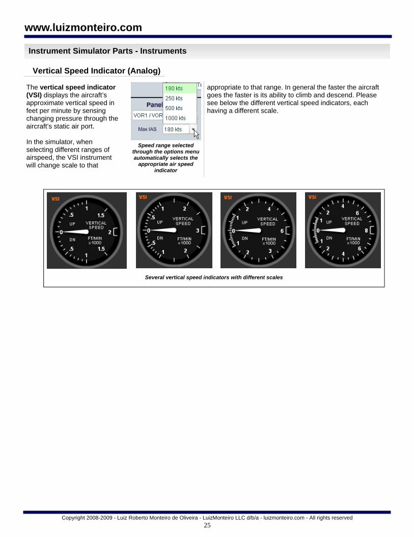
The vertical speed indicator (VSI) displays the aircraft’s approximate vertical speed in feet per minute by sensing changing pressure through the aircraft’s static air port. In the simulator, when selecting different ranges of airspeed, the VSI instrument will change scale to that
appropriate to that range. In general the faster the aircraft goes the faster is its ability to climb and descend. Please see below the different vertical speed indicators, each having a different scale.
Copyright 2008-2009 - Luiz Roberto Monteiro de Oliveira - LuizMonteiro LLC d/b/a - luizmonteiro.com - All rights reserved
www.luizmonteiro.com
Instrument Simulator Parts - Instruments
Vertical Speed Indicator (Analog)
Speed range selected through the options menu automatically selects the
appropriate air speed indicator
Several vertical speed indicators with different scales

26
Glide Slope pointers
Copyright 2008-2009 - Luiz Roberto Monteiro de Oliveira - LuizMonteiro LLC d/b/a - luizmonteiro.com - All rights reserved
www.luizmonteiro.com
NAV Warning Flag
Course Deviation bar (CDI) needle
To / From Indicators
Lubber Line
Course select knob
Course Deviation scale
Course select pointer Points to the course selected by the OBS Course Deviation Indicator (CDI) needle Shows aircraft's deviation from the course. Sensitivity depends on the type of navigational facility (navaid). To / From Indicator Shows an arrow flag pointing to the appropriate To or From region if the aircraft is positioned there and adequate signals are received. NAV Warning Flag When not receiving adequate VOR or Localizer signals such as when the aircraft is out of range or in the cone of confusion, the NAV flag will be displayed
Course select knob Selects the course referenced by the HSI instrument Glide Slope pointers If the navigational facility has a glide slope, positioning the aircraft above or below the glide slope causes the glide slope pointers to move in the opposite direction (provided the aircraft is within rage of the signal) Lubber line The line that is aligned with the longitudinal axis of the aircraft reinforcing the heading. Heading select knob Moves the heading bug that is used as a reference for the pilot.
Instrument Simulator Parts - Instruments
HSI (Horizontal Situation Indicator) - (Analog)
The HSI instrument displays the aircraft’s position relative to a navigational facility located on the ground at a known position. This instrument is dependent on receiving VHF type frequencies from the facility. In the actual aircraft the frequency is set through a radio panel and the facility is selected by that frequency. In this
simulator the HSI instrument is set by default to the Navaid 1 facility. However, it can be changed to reference Navaid 2 through the NAV 1 and NAV 2 “Radio” panel in the “General Settings” tab. The type of facility can be selected through the “Navaid settings” panel.
Navaid 1
Course select pointer
Glide Slope deviation scale
Heading select knob
Heading select bug
Navaid 2

27
Copyright 2008-2009 - Luiz Roberto Monteiro de Oliveira - LuizMonteiro LLC d/b/a - luizmonteiro.com - All rights reserved
www.luizmonteiro.com
NAV Flag
Course Deviation Indicator (CDI) needle
To / From Indicator
Course Index
Omnibearing Selector (OBS) knob
Glide Slope needle
GS Flag
Course Index Points to the course selected by the OBS Course Deviation Indicator (CDI) needle Shows aircraft's deviation from the course. Sensitivity depends on the type of navigational facility (navaid). To / From Indicator Shows an arrow flag pointing to the appropriate To or From region if the aircraft is positioned there and adequate signals are received. NAV Flag When not receiving adequate VOR or Localizer signals such as when the aircraft is out of range or in the cone of confusion, the NAV flag will be displayed
Omnibearing Selector (OBS) knob Selects the course referenced by the VOR instrument Glide Slope needle If the navigational facility has a glide slope, positioning the aircraft above or below the glide slope causes the glide slope needle to move in the opposite direction (provided the aircraft is within rage of the signal) GS Flag When not receiving adequate Glide Slope signals, such as when the aircraft is out of range, the GS flag will appear.
Instrument Simulator Parts - Instruments
VOR / Glide Slope (VOR 1) instrument (Analog)
The VOR / Glide Slope (VOR 1) instrument displays the aircraft’s position relative to a navigational facility located on the ground at a known position. This instrument is dependent on receiving VHF type frequencies from the facility. In the actual aircraft the frequency is set through a radio panel and the facility is selected by that frequency. In this simulator the VOR 1 instrument is set to the Navaid 1
facility by default. However, it can be changed to reference Navaid 2 through the NAV 1 and NAV 2 “Radio” panel in the “General Settings” tab. The type of facility can be selected through the “Navaid settings” panel. The glide slope function allows for vertical navigation when the facility such as a ILS transmits the glide slope signal.
Navaid 1 Navaid 2
28
Copyright 2008-2009 - Luiz Roberto Monteiro de Oliveira - LuizMonteiro LLC d/b/a - luizmonteiro.com - All rights reserved
www.luizmonteiro.com
NAV Flag
Course Deviation Indicator (CDI) needle
To / From Indicator
Course Index
Omnibearing Selector (OBS) knob
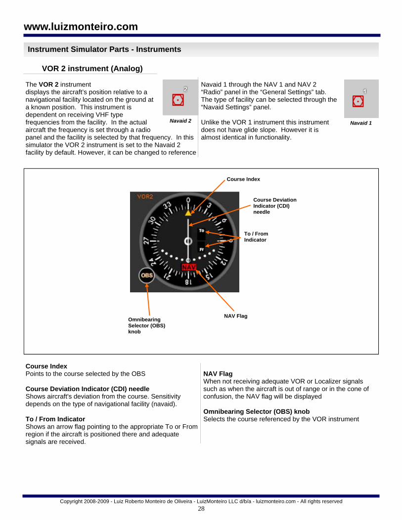
Course Index Points to the course selected by the OBS Course Deviation Indicator (CDI) needle Shows aircraft's deviation from the course. Sensitivity depends on the type of navigational facility (navaid). To / From Indicator Shows an arrow flag pointing to the appropriate To or From region if the aircraft is positioned there and adequate signals are received.
NAV Flag When not receiving adequate VOR or Localizer signals such as when the aircraft is out of range or in the cone of confusion, the NAV flag will be displayed Omnibearing Selector (OBS) knob Selects the course referenced by the VOR instrument
Instrument Simulator Parts - Instruments
VOR 2 instrument (Analog)
The VOR 2 instrument displays the aircraft’s position relative to a navigational facility located on the ground at a known position. This instrument is dependent on receiving VHF type frequencies from the facility. In the actual aircraft the frequency is set through a radio panel and the facility is selected by that frequency. In this simulator the VOR 2 instrument is set to the Navaid 2 facility by default. However, it can be changed to reference
Navaid 1 through the NAV 1 and NAV 2 “Radio” panel in the “General Settings” tab. The type of facility can be selected through the “Navaid Settings” panel. Unlike the VOR 1 instrument this instrument does not have glide slope. However it is almost identical in functionality.
Navaid 2 Navaid 1

29
The RMI instrument displays the aircraft’s position relative to a navigational facility located on the ground at a known position, much like the previous instruments. However instead of using needles that show the deviation from the selected course this instrument is basically a heading indicator with arrows that point to the navaid facilities chosen. This particular RMI is capable of receiving signals from two simultaneous navaids and choose between three different navaids. This instrument is dependent on receiving VHF type frequencies from the facility for VOR type signals and frequencies for NDB type facilities. In the actual aircraft the frequency is set through a radio panel
and the facility is selected by that frequency. In this simulator the NAV 1 selection is set to the Navaid 1 facility, the NAV 2 selection to Navaid 2, and the ADF to Navaid 3. The types of facilities can be selected through the “Navaid settings” panel.
Copyright 2008-2009 - Luiz Roberto Monteiro de Oliveira - LuizMonteiro LLC d/b/a - luizmonteiro.com - All rights reserved
www.luizmonteiro.com
Green hollow needle
Heading
ADF / NAV 1 toggle button
Yellow solid needle selection flag
Compass card
Heading Points to the heading on the rotating compass card Yellow solid and green hollow needles Point to the selected navaid relative to the aircraft’s position. The two needles have two distinct behaviors when not receiving an adequate signal. In this particular RMI the needle associated with a VOR type navaid will always point to the 180 heading of the RMI when not receiving a signal. The needle associated with the NDB type signal will stay at 3 o'clock position regardless of the heading when not receiving a signal. Compass card A card that rotates to display the aircraft’s heading under the heading mark.
ADF / NAV 1 and ADF / NAV 2 toggle buttons Used to select which needle will be associated to navaid 1 (NAV 1), navaid 2 (NAV 2), or navaid 3 (ADF). Yellow and green needle selection flags Show which navaid is selected through the toggle buttons.
Instrument Simulator Parts - Instruments
Radio Magnetic Indicator (RMI) instrument (Analog)
The RMI in this simulator can be set to two navaids simultaneously and be
selected from three different navaids
ADF / NAV 2 toggle button
Yellow solid needle
Green hollow needle selection flag

30
The automatic direction finder (ADF) instrument displays the aircraft’s position relative to a navigational facility located on the ground at a known position. It is basically a fixed (does not move automatically with the heading) compass card with an arrow that points to the navaid. In the actual aircraft the frequency is set through a
radio panel and the facility is selected by that frequency. In this simulator it is set to Navaid 3 (NDB) facility.
Copyright 2008-2009 - Luiz Roberto Monteiro de Oliveira - LuizMonteiro LLC d/b/a - luizmonteiro.com - All rights reserved
www.luizmonteiro.com
Heading Points to the heading on the rotating compass card Yellow needle Points to navaid 3 (NDB) when receiving adequate signals from that facility. When not receiving adequate signals the needle will not point to any particular direction and the instrument will become unreliable. In actual aircraft the pilot will need to continuously monitor a Morse code signal transmitted through the frequency to determine if those signals are being received or not. Compass card A card that can be rotated manually using the heading knob to set the card to the aircraft’s heading. Note that unlike the RMI, the ADF’s compass card does not rotate automatically with the heading. Heading knob Used to rotate the compass card.
Instrument Simulator Parts - Instruments
Automatic Direction Finder (ADF) instrument (Analog)
Navaid 3
Heading
Heading knob
Compass card
Yellow needle

31
The main instrument layout can be modified in the options panel under “Panel Setting”. This allows the user to choose which main navigation instruments will be displayed. The instruments that are not displayed with the main instruments will be in the “Navaid Information” tab under the category “Complementary / Analogous Instruments”. This way the user can compare the similarities between the HSI and the VOR, or the RMI and ADF instruments. The table below shows which instruments are visible in different panel settings.
Copyright 2008-2009 - Luiz Roberto Monteiro de Oliveira - LuizMonteiro LLC d/b/a - luizmonteiro.com - All rights reserved
www.luizmonteiro.com
Instrument Simulator Parts - Instrument Layout (Analog Panel)
Main Instruments Layout—Analog Instruments
Main instrument panel layout
1 2 3
4 5 6
7 8 9
HSI / VOR2 / ADF VOR1 / VOR2 / RMI VOR1 / VOR2 / ADF
1 1 1
2 2 2
3 3 3
4 4 4
5
6 6 6
7
8 5 5
ASI
AI
ALT
TC
HSI
VSI
RMI
HI
VOR1 8 8
VOR2 9 9 9
ADF 7 7
HIS / VOR2 / RMI
1
2
3
4
5
6
7
8
9

32
Navaid 1 ( VOR, VOR DME, VORTAC, LOC,
ILS, LOC BC, LDA, SDF types)
Navaid 2 ( VOR, VOR DME, VORTAC types)
Navaid 3 (NDB type)
HSI Yes* Yes* No
RMI Yes* ( via NAV1 selection )
Yes* ( via NAV2 selection )
Yes** ( via ADF selection )
VOR1 Yes* Yes* No
VOR2 Yes* Yes* No
ADF No No Yes**
DME Yes* ( v ia NAV1 selection )
Yes* ( v ia NAV2 selection )
No
Each navigational instrument is associated with one or more navaids. The table below lists these associations.
Copyright 2008-2009 - Luiz Roberto Monteiro de Oliveira - LuizMonteiro LLC d/b/a - luizmonteiro.com - All rights reserved
www.luizmonteiro.com
Instrument Simulator Parts - Instrument - Navaid Association
Navaid Association
* In an actual aircraft the selection is done through a NAV radio. Through it, it is possible to select any compatible navigational aid via a frequency in megahertz. In this simulator this is done via the NAV 1 and 2 “Radios” located in the General Settings section. The default setting is NAV 1 radio tuned to Navaid 1 and the NAV 2 radio tuned to Navaid 2. Do not confuse Navaid and NAV. The Navaid is the transmitter on the ground which is used by the instruments in the aircraft through the NAV radios. Therefore NAV is the navigation radio that can tune VOR and localizer type frequencies. Usually you have two in the aircraft (NAV 1 and NAV 2) and they can be tuned to a compatible Navaid on the ground. Different instruments will use the input from NAV 1 and 2. This is shown in the chart above. NAV 1 and 2 radios are not compatible with NDB frequencies so there is a separate radio for the NDB Navaid which is used by the ADF instrument. ** In an actual aircraft there would be an ADF radio which would be used to select an NDB frequency in kilohertz that would be used for the ADF type instruments. However, since we are using only one NDB facility there is no ADF radio displayed on the simulator.
There are three different navaids available in this simulator

33
Copyright 2008-2009 - Luiz Roberto Monteiro de Oliveira - LuizMonteiro LLC d/b/a - luizmonteiro.com - All rights reserved
www.luizmonteiro.com
VOR / Localizer and Glide Slope Simulation
Course Deviation Needle Deflection
Positioning the aircraft left or right of course will cause needle to deviate. The direction depends on several factors.
CDI needle deflection
CDI needle deflection

34
Copyright 2008-2009 - Luiz Roberto Monteiro de Oliveira - LuizMonteiro LLC d/b/a - luizmonteiro.com - All rights reserved
www.luizmonteiro.com
VOR / Localizer and Glide Slope Simulation (cont.)
NAV Flag When not receiving adequate VOR or Localizer signals such as when the aircraft is out of range or in the cone of confusion, the NAV flag will be displayed
NAV Flag
Glide Slope (GS) Flag
Cone of Confusion
GS Flag When not receiving adequate Glide Slope signals, such as when the aircraft is out of range, the GS flag will appear. In this case the aircraft is too high.
35
Copyright 2008-2009 - Luiz Roberto Monteiro de Oliveira - LuizMonteiro LLC d/b/a - luizmonteiro.com - All rights reserved
www.luizmonteiro.com
VOR / Localizer and Glide Slope Simulation (cont.)
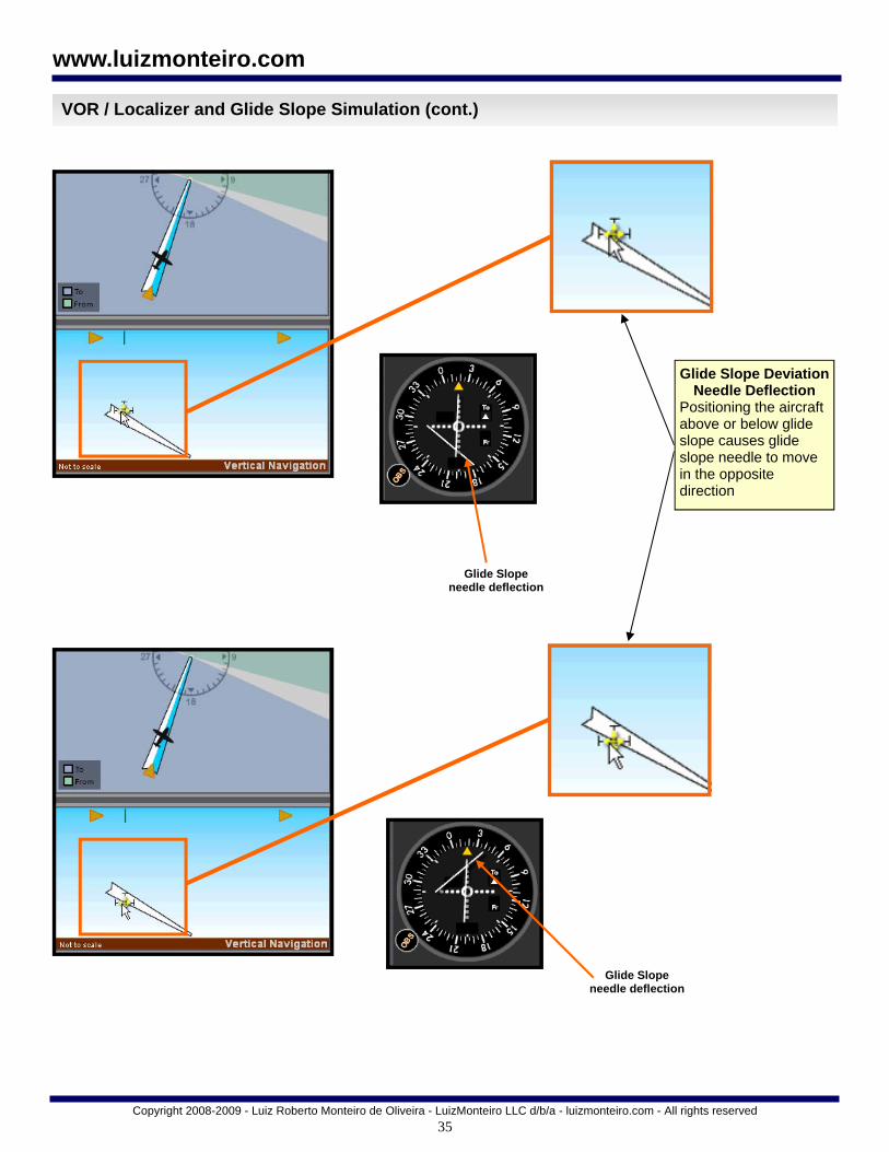
Glide Slope Deviation Needle Deflection
Positioning the aircraft above or below glide slope causes glide slope needle to move in the opposite direction
Glide Slope needle deflection
Glide Slope needle deflection

36
Copyright 2008-2009 - Luiz Roberto Monteiro de Oliveira - LuizMonteiro LLC d/b/a - luizmonteiro.com - All rights reserved
www.luizmonteiro.com
Glass (Digital) Panel - Main Parts
Clear and Enter key for use with panel
menus
FMS (flight management
system) knob for use with panel menus
NAV radio selection display
NAV 1 / NAV 2 selection knob CRS / BARO
setting knob
Magnetic Compass
Softkeys
Altitude bug knob
Heading bug knob
Standby / Active navaid selection
button
Altimeter
NAV 1 / 2 course
DME display box
Attitude Indicator
Vertical Speed Indicator (VSI)
Air Speed Indicator (ASI)
BRG1 display box (analogous to RMI 1 information) BRG1 needle
(analogous to RMI 1 information)
BRG2 display box (analogous to RMI 2 information)
BRG2 needle (analogous to
RMI 2 information)
*G1000 is a registered trade mark of Garmin Ltd. This product has not been endorsed by Garmin or intended as a substitute for training in Garmin approved G1000 simulators.
The glass cockpit panel is based on the style of the popular G1000* instrument display. Many other digital avionics panels also have a similar feel. This panel is adapted to the simulator for basic instrument training, which is what the simulator was meant for. Many of the more complex functions that the actual G1000* would have are beyond the scope of the simulator and not included or replicated. Only buttons that are functional have been placed on the panel. At the moment the panel provides VOR, ADF, DME, RMI, and ILS navigation capabilities, however GPS navigation is not included.
This panel is also linked to the analog instrument panel. If you change the settings on this panel the equivalent settings will be changed on the analog instrument panel and vice versa. This feature is great when comparing the differences and similarities between the two panels, particularly for students and pilots transitioning from a analog type instrument aircraft to a glass cockpit panel aircraft. It's also possible to compare both types of instruments simultaneously on the simulator by pressing "I" to activate the dual panel view.
G1000* Style Panel
Rate of turn indicator
Compass rose heading indicator
Slip / skid Indicator

37
Copyright 2008-2009 - Luiz Roberto Monteiro de Oliveira - LuizMonteiro LLC d/b/a - luizmonteiro.com - All rights reserved
www.luizmonteiro.com
Instrument Simulator Parts - Relative Positions Window
The Relative Positions window can be toggled on and off by pressing the “R” key. This window shows the relative relationships on the map for the aircraft, navaid’s, and intersection. You can use this window while positioning these items on the map or simply to see exactly where they’re located. In the case of the intersection symbol it is also possible to set it
precisely relative to the navaid(s) by using the “Position Wizard” button under the Navaid settings section. This is useful when the intersection is needed for holding patterns or practicing airway navigation. Other position wizard’s are available for the navaids and aircraft in the “Others Settings” tab in the options menu.
Position Wizard launches a separate window where the user can select the exact placement of the intersection manually
Relative Positions Window
Relative Positions

38
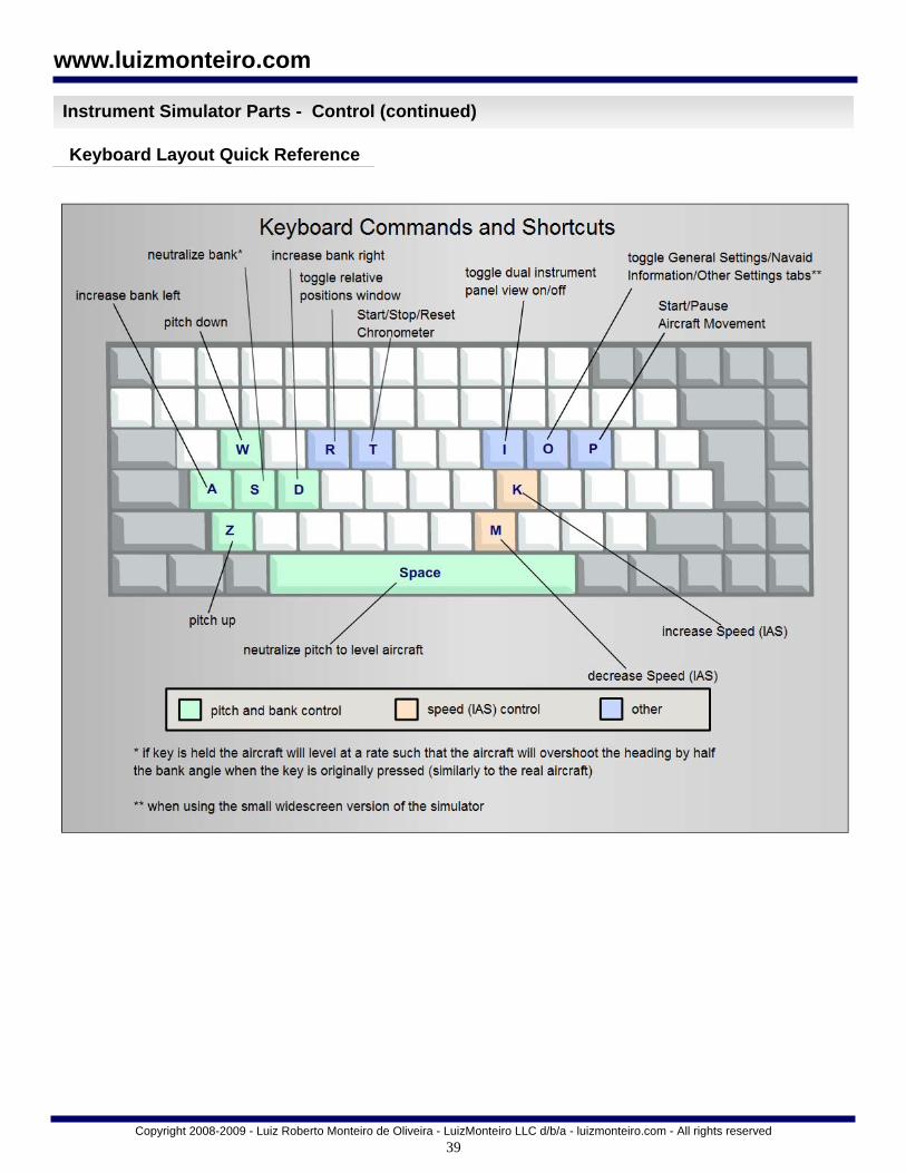
The following are the keys that control the aircraft: "A" - increase bank left "D" - increase bank right "S" - neutralize bank (if key is held the aircraft will level at
a rate such that the aircraft will overshoot the heading by half the bank angle when the key is originally pressed (similarly to the real aircraft.)
"W" - pitch down "Z" - pitch up "Space Bar" -neutralize pitch to level aircraft "K" - increase speed "M" -decrease speed IMPORTANT KEYBOARD CONTROL NOTE: The simulator start button must be pressed and the aircraft rotating-arround-the-
globe icon must be moving for the keyboard movement commands to work. In addition, clicking outside the simulator may cause the computer to stop sending keyboard commands to the simulator. You must click on any blank portion of the simulator to allow transfer keyboard of commands to it. You can also still drag and reposition the aircraft even if it is moving Other keyboard commands: "R" - toggle relative positions window "T" - starts/stops/resets the chronometer "O" - toggle General Settings/Navaid Information tabs
when using the small widescreen version of the simulator.
"P" - starts/pauses aircraft movement " I " - toggle dual analog and digital panel views
aircraft rotating-arround-the-globe icon
Copyright 2008-2009 - Luiz Roberto Monteiro de Oliveira - LuizMonteiro LLC d/b/a - luizmonteiro.com - All rights reserved
www.luizmonteiro.com
Instrument Simulator Parts - Control
Keyboard Control of the Simulator
Current indicated airspeed value
Current rate of turn bar indication
Current indicated air-speed bar indication
Target indicated airspeed value
Target indicated air-speed bar indication
Current rate of turn value
Current bank angle value
Current bank angle bar indication
Target bank angle bar indication
Current climb rate value
Current climb rate bar indication
Target climb rate value
Target climb rate bar indication
Aircraft Motion Control Screen (controlled though keyboard)
39
Copyright 2008-2009 - Luiz Roberto Monteiro de Oliveira - LuizMonteiro LLC d/b/a - luizmonteiro.com - All rights reserved
www.luizmonteiro.com
Instrument Simulator Parts - Control (continued)
Keyboard Layout Quick Reference

40
Copyright 2008-2009 - Luiz Roberto Monteiro de Oliveira - LuizMonteiro LLC d/b/a - luizmonteiro.com - All rights reserved
www.luizmonteiro.com
Instrument Simulator Parts - Control (continued)
Keyboard Control Example
Task: - Initial conditions: the aircraft is straight and level and at
a 45° heading. - Fly straight and level for one minute - Turn right to the heading of 180° - Fly at that heading for 45 seconds Use standard rate turns
1
2
3
4
Position 1:
Assuming that the is straight and level and at a 45° heading (this is the default state when the simulator starts). Press the start button (shortcut “P”) on the aircraft motion control, to begin aircraft movement (notice the aircraft icon rotating around the globe). On the chronometer, press the start button to initiate timing (you can use a shortcut “T”). Let the aircraft fly for one minute on the chronometer. Position 2 Press and hold the “D” key to turn right until the light green bar reaches the limit. In this case based on the airspeed the simulator automatically limits the bank to 17° which corresponds to the bank for a standard rate turn at that speed. Once the light green bar has reached the 17° limit,
you can release the “D” key. The light green bar determines the target bank. The dark green (the aircraft’s actual bank) bar will catch up to the light green bar indicating that the aircraft reached its selected bank.
Now that the aircraft is turning at a standard rate, take the time to stop the chronometer by clicking on “Stop”, and then resetting it by clicking on “Reset”. These two operations can also be done by pressing the “T” key twice. Position 3 When rolling out from a bank the aircraft will continue to turn during the rollout for about half of the initial bank angle in degrees. In this case the standard rate bank angle is 17°. Half of that (17°/2) is 8.5°. We can round that up to 9°. This means that if we want to level at a heading of 180° we must anticipate that turn by about 9° in this case 180° - 9° = 171°. Note that if the turn were to the left we would add 9° instead of subtract.
At 171° press the “S” key to level the bank until the light green bar is zero. The dark green bar, which is the actual bank, will follow.
(Continued on next page)
41
Copyright 2008-2009 - Luiz Roberto Monteiro de Oliveira - LuizMonteiro LLC d/b/a - luizmonteiro.com - All rights reserved
www.luizmonteiro.com
Instrument Simulator Parts - Control (continued)
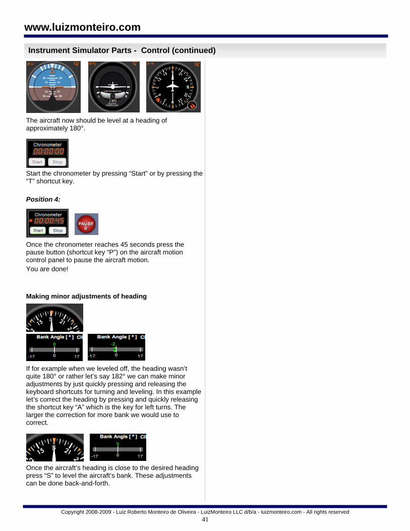
The aircraft now should be level at a heading of approximately 180°.
Start the chronometer by pressing “Start” or by pressing the “T” shortcut key. Position 4:
Once the chronometer reaches 45 seconds press the pause button (shortcut key “P”) on the aircraft motion control panel to pause the aircraft motion. You are done! Making minor adjustments of heading
If for example when we leveled off, the heading wasn’t quite 180° or rather let’s say 182° we can make minor adjustments by just quickly pressing and releasing the keyboard shortcuts for turning and leveling. In this example let’s correct the heading by pressing and quickly releasing the shortcut key “A” which is the key for left turns. The larger the correction for more bank we would use to correct.
Once the aircraft’s heading is close to the desired heading press “S” to level the aircraft’s bank. These adjustments can be done back-and-forth.

42
Copyright 2008-2009 - Luiz Roberto Monteiro de Oliveira - LuizMonteiro LLC d/b/a - luizmonteiro.com - All rights reserved
www.luizmonteiro.com
Positioning Aircraft Manually
Positioning Horizontally
Move Icon
Step 1 On the horizontal navigation panel move mouse pointer on the aircraft symbol until the yellow move icon appears
Step 2 Hold left mouse button down and drag aircraft to desired location and then release mouse button
Positioning Vertically
Aircraft Heading
Step 1 Move mouse pointer until the yellow move icon appears
Move Icon

43
Copyright 2008-2009 - Luiz Roberto Monteiro de Oliveira - LuizMonteiro LLC d/b/a - luizmonteiro.com - All rights reserved
www.luizmonteiro.com
Positioning Aircraft Manually (cont)
Step 2 Hold left mouse button down and drag aircraft up or down to change altitude then release mouse button
Positioning Vertically (cont.)
Note that it is also possible to position the aircraft horizontally using the vertical panel. When dragging the aircraft left to right/right to left in the vertical panel, the aircraft will also position itself horizontally parallel to the projection flags.
Question: What is the purpose of the Vertical Navigation panel? Answer: The Vertical Navigation Panel serves three purposes, which are: 1) Simulate the slant range error in DME readings 2) Enable the simulation of the glide slope 3) Allow other maneuvers where the user needs to change altitude

44
Copyright 2008-2009 - Luiz Roberto Monteiro de Oliveira - LuizMonteiro LLC d/b/a - luizmonteiro.com - All rights reserved
www.luizmonteiro.com
Setting Aircraft Heading Manually
Rotating Aircraft (North Up Selected)
Five Degree Clockwise
Rotate Icon
Step 1 Move mouse pointer until the rotate icon appears
Step 2 Hold left mouse button down until desired heading is selected
Aircraft Heading
One Degree Clockwise
Rotate Icon
Ten Degree Clockwise
Rotate Icon
Rotating Clockwise Faster
Place the mouse cursor near the aircraft over a region that is horizontally off the center of the aircraft. Placing the cursor on the right side will cause a positive number (+1, +5, or +10) to be displayed. For example, clicking on +5 will cause the heading to be changed 5 degrees to the right. Holding the button down and moving the cursor to the right will allow display of +20 and +45 which will cause very rapid rotation of the heading to the right. Releasing the button will cause rotation to stop.
Rotating Counterclockwise
Counterclockwise heading change is done in a similar fashion to clockwise except that the mouse is moved slightly to the left
One Degree Counterclockwise
Rotate Icon
Five Degree Counterclockwise
Rotate Icon
Ten Degree Counterclockwise
Rotate Icon

45
Copyright 2008-2009 - Luiz Roberto Monteiro de Oliveira - LuizMonteiro LLC d/b/a - luizmonteiro.com - All rights reserved
www.luizmonteiro.com
Setting Aircraft Heading Manually (Cont.)
Rotating Aircraft (Heading Up Selected) One Degree Clockwise
Rotate Icon
Five Degree Clockwise
Rotate Icon
North Up Deselected and Heading Up Selected
Step 1 Move mouse pointer to the right side (clockwise rotation) of the Navaid 1 until the rotate icon appears
Step 2 Hold left mouse button down until desired heading is selected. Move mouse further to the right side if a greater rate is desired.
Ten Degree Clockwise
Rotate Icon
Heading Value
Greater Rate Greater rate is obtained by moving the aircraft further to the side of Navaid 1. Moving right of the Navaid 1 increases Heading
Rotating Counterclockwise Counterclockwise heading change is done in a similar fashion to clockwise except that the mouse is moved slightly to the left
Ten Degree Counterclockwise
Rotate Icon
Five Degree Counterclockwise
Rotate Icon
One Degree Counterclockwise
Rotate Icon

46
Copyright 2008-2009 - Luiz Roberto Monteiro de Oliveira - LuizMonteiro LLC d/b/a - luizmonteiro.com - All rights reserved
www.luizmonteiro.com
Note that when changing the heading with heading up mode selected it may appear that the aircraft is moving around Navaid 1, but in reality it is not. In this example the aircraft has always remained in the same location only the heading has changed.
Setting Aircraft Heading Manually (cont.)
Heading Change Different heading but the aircraft is in the same position
North Up When switching back to the North up mode the aircraft still remains in the same position even though it may seem that the aircraft has moved around the Navaid

47
Copyright 2008-2009 - Luiz Roberto Monteiro de Oliveira - LuizMonteiro LLC d/b/a - luizmonteiro.com - All rights reserved
www.luizmonteiro.com
Setting Aircraft Heading Manually - Additional Ways
Activate “Shift Mode” Holding Shift key down and moving the cursor near the aircraft center will display a blue arrow extending from the center of the aircraft with the current direction of the arrow from the aircraft in degrees displayed on the line.
While holding the Shift key down and moving the mouse cursor around the map, the arrow radiating from the aircraft will follow the mouse constantly showing the direction from the aircraft.
Rotating Aircraft Using the “Shift” Key
Clicking the mouse button will change the aircraft heading to the current direction of the blue line. Release the Shift button to hide the blue line.
1
2
3
4

48
Copyright 2008-2009 - Luiz Roberto Monteiro de Oliveira - LuizMonteiro LLC d/b/a - luizmonteiro.com - All rights reserved
www.luizmonteiro.com
Setting Aircraft Heading Manually - Additional Ways (cont.)
Double clicking on the aircraft will cause a small window near the aircraft to open with the current heading in the edit box.
Rotating Aircraft Using the Entry Box
Changing the value in the edit box to any value from 1 to 360 will change the aircraft heading to that heading. Clicking on X or pressing Esc closes the window.
1
2
3
4

49
Copyright 2008-2009 - Luiz Roberto Monteiro de Oliveira - LuizMonteiro LLC d/b/a - luizmonteiro.com - All rights reserved
www.luizmonteiro.com
Setting the OBS and Other Knobs - Analog Panel
Changing the OBS Setting Changing the OBS setting is done in a similar fashion as setting the aircraft’s heading. Move cursor slightly right or left of the OBS knob until the “+1” (right) or “-1” (left) appears. Hold left mouse button down until desired setting is reached. For faster rate, move mouse slightly more to the side until the “+5”, “+10”, “- 5”, or “- 10” sign appears.
Increasing the OBS Setting
Decreasing the OBS Setting
OBS Setting
OBS Knob
Knob Rotation
Icon
Note that the same procedure can be used for other knobs in other instruments.
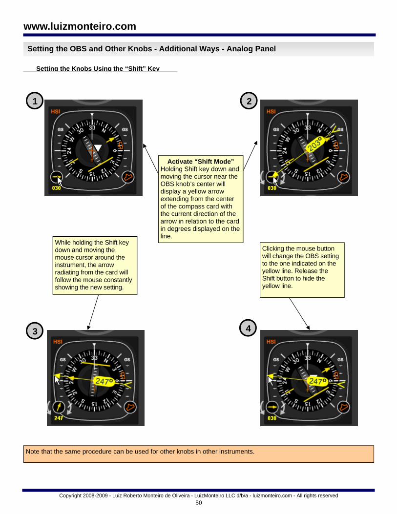
50
Copyright 2008-2009 - Luiz Roberto Monteiro de Oliveira - LuizMonteiro LLC d/b/a - luizmonteiro.com - All rights reserved
www.luizmonteiro.com
Setting the OBS and Other Knobs - Additional Ways - Analog Panel
Note that the same procedure can be used for other knobs in other instruments.
Activate “Shift Mode” Holding Shift key down and moving the cursor near the OBS knob’s center will display a yellow arrow extending from the center of the compass card with the current direction of the arrow in relation to the card in degrees displayed on the line.
While holding the Shift key down and moving the mouse cursor around the instrument, the arrow radiating from the card will follow the mouse constantly showing the new setting.
Clicking the mouse button will change the OBS setting to the one indicated on the yellow line. Release the Shift button to hide the yellow line.
1 2
3 4
Setting the Knobs Using the “Shift” Key

51
Copyright 2008-2009 - Luiz Roberto Monteiro de Oliveira - LuizMonteiro LLC d/b/a - luizmonteiro.com - All rights reserved
www.luizmonteiro.com
Setting the OBS and Other Knobs - Additional Ways - Analog Panel(cont.)
Note that the same procedure can be used for other knobs in other instruments.
Setting the Knobs Using the Entry Box
1 2
3 4
Double clicking on the OBS knob will cause a small window near the knob to open with the current setting in the edit box.
Changing the value in the edit box to any value from 1 to 360 will change the OBS setting. Clicking on X or pressing Esc closes the window.

52
Copyright 2008-2009 - Luiz Roberto Monteiro de Oliveira - LuizMonteiro LLC d/b/a - luizmonteiro.com - All rights reserved
www.luizmonteiro.com
Setting the CRS - Digital Panel
Changing the CRS Setting Changing the CRS setting is done in a similar fashion as setting the OBS for the analog panel. Move cursor on top of the CRS / BARO knob. Next move cursor slightly right or left of the CRS knob hot spot until the “+1” (right) or “-1” (left) appears. Hold left mouse button down until desired setting is reached. For faster rate, move mouse slightly more to the side until the “+5”, “+10”, “- 5”, or “- 10” sign appears.
VOR 1 (NAV 1) CDI
BARO Hot Spot
CRS / BARO Knob
Pressing the CDI softkey toggles between VOR 1 (NAV 1) and VOR 2 (NAV 2) selection. CRS knob always sets currently selected NAV.
CRS Hot Spot
CRS Setting Value
CRS Setting Value
Increment
CDI Softkey
VOR 2 (NAV 2) CDI

53
Copyright 2008-2009 - Luiz Roberto Monteiro de Oliveira - LuizMonteiro LLC d/b/a - luizmonteiro.com - All rights reserved
www.luizmonteiro.com
Setting the BARO - Digital Panel
Changing the BARO Setting Changing the BARO setting is done in a similar fashion as the CRS settingl. Move cursor on top of the CRS / BARO knob. Next move cursor slightly right or left of the BARO knob hot spot until the “+1” (right) or “-1” (left) appears. Hold left mouse button down until desired setting is reached. For faster rate, move mouse slightly more to the side until the “+5”, “+10”, “- 5”, or “- 10” sign appears.
BARO Hot Spot
CRS / BARO Knob
CRS Hot Spot
BARO Setting value is the
instrument’s altimeter setting
CRS Setting Value
Increment
The station altimeter setting is available in
the “General Settings” section of the
“Options Menu”

54
Copyright 2008-2009 - Luiz Roberto Monteiro de Oliveira - LuizMonteiro LLC d/b/a - luizmonteiro.com - All rights reserved
www.luizmonteiro.com
Setting the Other Knobs - Digital Panel
FMS Outer knob Hot Spot
Altitude Bug
DME soft key
Clicking on the button sets HDG Bug to
the aircraft’s heading
Altitude bug setting
+ 1000 hot spot
Altitude Bug
+ 100 hot spot
- 1000 hot spot
+ 100 hot spot
Heading Bug
HDG bug hot spot
HDG bug
HDG Bug Setting Value
HDG Bug Setting Value
FMS Knob
FMS Inner knob Hot Spot
The FMS knob is usually used to select options in the glass panels menus. For example: pressing the DME soft key opens the DME tuning menu. The inner FMS knob is used to move the highlight option. Once the option is highlighted the ENT key above the FMS can be clicked to select the new DME option. The CLR button is used to close the Menu.
DME Tuning Menu
CLR and ENT buttons
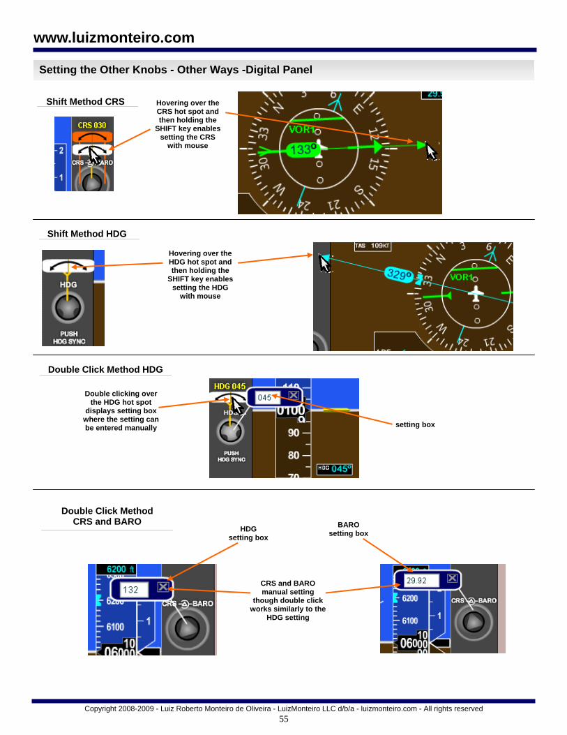
55
Copyright 2008-2009 - Luiz Roberto Monteiro de Oliveira - LuizMonteiro LLC d/b/a - luizmonteiro.com - All rights reserved
www.luizmonteiro.com
Setting the Other Knobs - Other Ways -Digital Panel
Shift Method CRS Hovering over the CRS hot spot and then holding the
SHIFT key enables setting the CRS
with mouse
Hovering over the HDG hot spot and then holding the
SHIFT key enables setting the HDG
with mouse
Shift Method HDG
Double Click Method HDG
Double clicking over the HDG hot spot
displays setting box where the setting can be entered manually setting box
Double Click Method CRS and BARO
CRS and BARO manual setting
though double click works similarly to the
HDG setting
BARO setting box
HDG setting box

56
Copyright 2008-2009 - Luiz Roberto Monteiro de Oliveira - LuizMonteiro LLC d/b/a - luizmonteiro.com - All rights reserved
www.luizmonteiro.com
Setting the NAV Radios - Digital Panel
VOR 1 is associated With NAV 1
Toggle active and standby navaids
where blue rectangle Is highlighted
NAV 1 active navaid
Navaid 2 refers to the navigational
facility 2 on the map
Toggle blue rectangle highlight between NAV 1 and NAV 2
NAV 2 active navaid
VOR 2 is associated With NAV 2
Navaid 1 refers to the navigational
facility 1 on the map
The panel above performs the identical function
of the NAV 1 and 2 radio settings on the “General
Settings” Panel
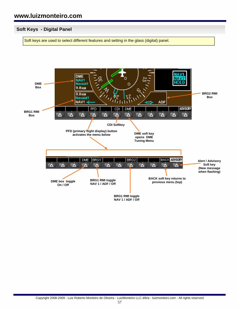
57
Copyright 2008-2009 - Luiz Roberto Monteiro de Oliveira - LuizMonteiro LLC d/b/a - luizmonteiro.com - All rights reserved
www.luizmonteiro.com
Soft Keys - Digital Panel
Soft keys are used to select different features and setting in the glass (digital) panel.
PFD (primary flight display) button activates the menu below
BRG1 RMI toggle NAV 1 / ADF / Off
Alert / Advisory Soft key
(New message when flashing)
BRG1 RMI toggle NAV 1 / ADF / Off
CDI Softkey
DME soft key opens DME Tuning Menu
BRG1 RMI Box
BRG2 RMI Box
DME Box
DME box toggle On / Off
BACK soft key returns to previous menu (top)

58
Copyright 2008-2009 - Luiz Roberto Monteiro de Oliveira - LuizMonteiro LLC d/b/a - luizmonteiro.com - All rights reserved
www.luizmonteiro.com
Dual Panel View
Toggling Dual Panel View On and Off Pressing “I” toggles dual panel view on and off. This is a great feature to compare analog and digital panel functionality. Both panel functions are tied together. Changing settings in the analog panel for example will cause the equivalent settings to be changed in the digital panel as well. For example, if setting the course in the analog HSI instrument the same course will be set on the digital glass instrument panel.
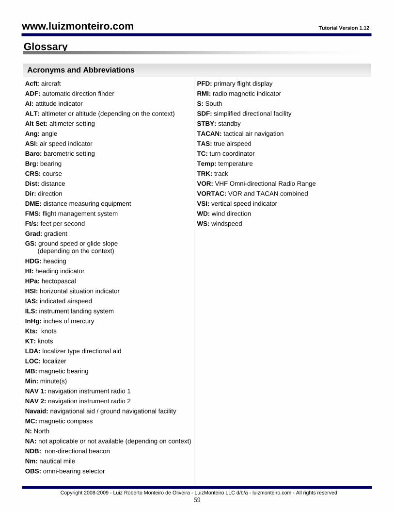
59
Copyright 2008-2009 - Luiz Roberto Monteiro de Oliveira - LuizMonteiro LLC d/b/a - luizmonteiro.com - All rights reserved
www.luizmonteiro.com
Glossary
Acft: aircraft
ADF: automatic direction finder
AI: attitude indicator
ALT: altimeter or altitude (depending on the context)
Alt Set: altimeter setting
Ang: angle
ASI: air speed indicator
Baro: barometric setting
Brg: bearing
CRS: course
Dist: distance
Dir: direction
DME: distance measuring equipment
FMS: flight management system
Ft/s: feet per second
Grad: gradient
GS: ground speed or glide slope (depending on the context)
HDG: heading
HI: heading indicator
HPa: hectopascal
HSI: horizontal situation indicator
IAS: indicated airspeed
ILS: instrument landing system
InHg: inches of mercury
Kts: knots
KT: knots
LDA: localizer type directional aid
LOC: localizer
MB: magnetic bearing
Min: minute(s)
NAV 1: navigation instrument radio 1
NAV 2: navigation instrument radio 2
Navaid: navigational aid / ground navigational facility
MC: magnetic compass
N: North
NA: not applicable or not available (depending on context)
NDB: non-directional beacon
Nm: nautical mile
OBS: omni-bearing selector
PFD: primary flight display
RMI: radio magnetic indicator
S: South
SDF: simplified directional facility
STBY: standby
TACAN: tactical air navigation
TAS: true airspeed
TC: turn coordinator
Temp: temperature
TRK: track
VOR: VHF Omni-directional Radio Range
VORTAC: VOR and TACAN combined
VSI: vertical speed indicator
WD: wind direction
WS: windspeed
Acronyms and Abbreviations
Tutorial Version 1.12

60
End
Copyright 2008-2009 - Luiz Roberto Monteiro de Oliveira - LuizMonteiro LLC d/b/a - luizmonteiro.com - All rights reserved
www.luizmonteiro.com
®