navigator for ashrae 90.1 app-g prm user guide · the ashrae 90.1 app – g prm navigator functions...
TRANSCRIPT

VE-GaiaASHRAE 90.1 App-G PRM Navigator
Version 6.4.05

ASHRAE 90.1 App-G PRM Navigator
Contents
1. VE-Gaia: PRM Navigator Introduction ......................................................................................5
2. VE-Gaia: PRM Navigator – What makes it different? ...............................................................5
3. VE-Gaia: ASHRAE 90.1 App-G PRM Navigator Structure........................................................5
4. VE-Pro Modules to utilize with PRM Navigator .........................................................................6
5. Preliminary Data Setup.............................................................................................................8
Workflow concept .........................................................................................................................9
Site, Location and Climate............................................................................................................9
Prototype Data (ASHRAE Baseline)...........................................................................................12
Fossil Fuel Type .........................................................................................................................13
Update Profile Working Week Order ..........................................................................................13
Building Geometry......................................................................................................................15
Settings...................................................................................................................................15
Input Options ..........................................................................................................................18
Site Obstructions & Shading.......................................................................................................22
Input Options ..........................................................................................................................22
Set Selected Zones to Obstructions .......................................................................................22
Building Orientation ....................................................................................................................23
Room/Zone Group Assignment ..................................................................................................23
Solar Shading Calculation ..........................................................................................................29
6. Envelope Thermo-Physical Properties....................................................................................30
ASHRAE Baseline Constructions ...............................................................................................31
Proposed Building Constructions ...............................................................................................33
Improve Baseline ....................................................................................................................33
Custom Construction Type .....................................................................................................33
Surface Assignment ...................................................................................................................35
Above Ground.........................................................................................................................35
Ground Contact ......................................................................................................................35
7. Room/Zone Thermal Template Data ......................................................................................35
Space Classification ...................................................................................................................36
Internal Heat Gains ....................................................................................................................36
Equipment...............................................................................................................................36
People.....................................................................................................................................36
Lighting ...................................................................................................................................36

ASHRAE 90.1 App-G PRM Navigator
ASHRAE 62.1 Parameters .........................................................................................................38
Air Exchange ..............................................................................................................................39
Outside Air Ventilation Rate (simple) ......................................................................................40
Infiltration ................................................................................................................................40
Other End Uses..........................................................................................................................41
Exterior Lighting......................................................................................................................41
Elevators.................................................................................................................................43
Service Hot Water...................................................................................................................43
8. HVAC Systems .......................................................................................................................45
Assign Rooms.........................................................................................................................45
System Schedules ..................................................................................................................46
Baseline system......................................................................................................................47
Edit Current Baseline..............................................................................................................47
System Parameters ................................................................................................................49
Proposed System ...................................................................................................................50
Improve Upon Baseline...........................................................................................................50
Edit Current Proposed ............................................................................................................50
OR Custom System ................................................................................................................51
AHU System Parameters........................................................................................................51
Room conditions (Set points)..................................................................................................51
9. Other Input Data .....................................................................................................................53
Renewable Energy Systems ......................................................................................................53
Utility Tariffs................................................................................................................................55
Introduction .............................................................................................................................55
Overview.................................................................................................................................55
Fossil Fuel Type .....................................................................................................................62
10. Generate Baseline...............................................................................................................63
Generate the Baseline Model .....................................................................................................63
11. Sizing Runs .........................................................................................................................66
Room Load Calculations ............................................................................................................66
Assign Room Sizing Data...........................................................................................................67
System Load Calculations..........................................................................................................67
Update Fan And Coil Sizing Data...............................................................................................68
Sizing Reports ............................................................................................................................69
Proposed ................................................................................................................................69
Baseline 0°..............................................................................................................................71

ASHRAE 90.1 App-G PRM Navigator
Baseline 90°............................................................................................................................71
Baseline 180°..........................................................................................................................71
Baseline 270°..........................................................................................................................71
12. Simulations..........................................................................................................................74
Proposed Model Simulation........................................................................................................74
0° Baseline Model Simulation.....................................................................................................74
Full PRM Simulation...................................................................................................................75
13. Cost.....................................................................................................................................75
14. Results ................................................................................................................................76
Set Parameters For “Unmet Load Hour” Temperature Tests .....................................................77
BPRM Report .............................................................................................................................80
User Details ............................................................................................................................80
Data For Tables 1.3 and 1.4 ...................................................................................................80
Cost Savings Summary – Table 1.8.2(b) ................................................................................81
Energy Savings Summary – Table 1.8.2.................................................................................81
Baseline Costs – Table 1.8.1(b)..............................................................................................82
Baseline Energy – Table 1.8.1................................................................................................82
Full Report ..............................................................................................................................83
Detailed Simulation Reports .......................................................................................................89
Proposed ................................................................................................................................89
Baseline 0°..............................................................................................................................92
Baseline 90°............................................................................................................................92
Baseline 180°..........................................................................................................................92
Baseline 270°..........................................................................................................................92
ASHRAE 62.1.............................................................................................................................93
Display Selected Reports ...........................................................................................................93

ASHRAE 90.1 App-G PRM Navigator
ASHRAE 90.1 App-G PRM Navigator Page 5
1. VE-Gaia: PRM Navigator Introduction
VE-Gaia = Step-by -step analysis workflows - - VE-Gaia’s complete workflow environment isdriven by “step-by-step” smart navigation that opens wide the power of IES analysis. A series ofNavigators guide users through a range of tasks; from advanced modelling, to energy/carbonanalysis, to LEED and Green Star credit interrogation and report creation
2. VE-Gaia: PRM Navigator – What makes it different?
The PRM Navigator establishes a ‘workflow concept’ to guide the user through the PerformanceRating Method process. It particularly targets the USGBC LEED Energy & Atmosphere Credit 1 –Optimize Energy Performance energy modeling process, however it can be used in a number ofother ways as well. For example, the following Green Rating Systems (but not limited to) that areused in different parts of the world also point to ASHRAE 90.1 Appendix G – PRM process as therequirement for energy credits as well:
- LEED Canada (points to ASHRAE 90.1-2007)- Estidama (points to ASHRAE 90.1-2007)- LEED India (points to ASHRAE 90.1-2004*)
*template data within the PRM navigator is based on 90.1-2007 version, so user will currentlyneed to edit the input assumptions to run analysis for a different version of ASHRAE 90.1.
What makes it different from other tools that are used for energy modeling?- It could be generally categorized as a wizard, but it’s a ‘smart navigator’: The PRM
Navigator not only allows users to implement and manage the PRM process in a new way italso ‘navigates’ how the user can access the different VE-Pro modules required (seerequired module list below) to complete the different types of analysis involved in the PRMprocess in a streamlined manner. The user is also given real-time feedback along the wayso they can compare how their design stacks up to the 90.1 requirements.
- 5 in 1: All five models (proposed design + 4 baseline models) required for the PRM live inone file versus having to maintain the data across five different model files.
- Input Data Once and Manage Edits effectively: The manner in which inputs are handledallows the user to input the data within the model, which influences the inputs in all fivemodels.
- Creating the Baseline Models: The required baseline models are generated from theproposed design filtered through the requirements of ASHRAE 90.1 Appendix G, at thestage in the process the user chooses to develop them. The user has two choices…
3. VE-Gaia: ASHRAE 90.1 App-G PRM Navigator Structure
The main objectives of the VE-Gaia PRM (Performance Rating Method) Navigator are to:
1. Manage the overall process, including inputs, edits and cycles of the PRM (ASHRAE90.1 Appendix G)
2. Provide industry recognized defaults and input selection options (ASHRAE standardsdata as the basis) to assist the process

ASHRAE 90.1 App-G PRM Navigator
ASHRAE 90.1 App-G PRM Navigator Page 6
A range of individual software modules and features are available within the VE-Pro suite whichcan be used to construct a detailed PRM model. The user needs to manually switch betweenmodules and know at which point in the process a specific feature needs to be used. In summary itcan be difficult to understand how each module and feature fits into the overall PRM workflowanalysis process.
The VE-Gaia PRM Navigator is a tool which brings all of the individual VE-Pro modules andfeatures together in a single area and presents the user with step-by-step smart navigation andmanagement of the PRM workflow and analysis process. The Navigator is driven through thesuccessful execution of specific actions and commands which are activated by the user in adefined sequence.
This smart navigation leads the user through the process of basic geometry creation, toconstructions/thermal data assignment, and ultimately to the automatic generation of a full set ofPRM compliant results which are presented in a format similar to the LEED EAc1 Letter Template.
The Navigator also provides the user with predefined prototypical ASHRAE data which can beused to populate the model with default baseline information.
The main structure of the PRM Navigator workflow includes:1. Preliminary Data setup2. Envelope Thermo/Physical Properties3. Room/Zone Thermal Template Data4. HVAC systems5. Other Input Data6. Generate Baseline7. Sizing runs8. Simulations9. Results
The ASHRAE 90.1 App – G PRM Navigator functions as a series of hyperlinks that are accessedwithin the smart navigator tree structure that is located on the upper left side of the interface. Thehyperlinks take the user to the relevant VE-Pro module and dialog box to complete the tasksassociated with that topic.
Note: that the user can increase the size of this area by dragging downward on the borderbetween the VE-Gaia workflows area and the Rooms area.
4. VE-Pro Modules to utilize with PRM Navigator
The following list of VE-Pro modules are classified into two categories – required and beneficial. Itis recommended that the user confirm which VE-Pro modules they have licenses for, so that theyhave the full capability of the PRM navigator available.
Required:o ModelITo Suncast

ASHRAE 90.1 App-G PRM Navigator
ASHRAE 90.1 App-G PRM Navigator Page 7
o ApacheSimo ApacheLoadso ApacheHVAC
Beneficial Based on what type of efficiency measures or HVAC system is being analyzed:o FlucsPro, LightPro, Radianceo Macroflo
Figure 1 provides an over of the Virtual Environment software platform. The upper right portion ofthe diagram identifies the four tiers of the VE comprised of:
- VE-Ware- VE-Toolkits- VE-Gaia- VE-Pro
For additional information on the four levels go to “How and when should I integrate performanceanalysis for sustainable design?”
The lower portion of Figure 1 identifies the different modules that a part of VE-Pro. For additionalinformation on the different modules please go to - http://www.iesve.com/Software/VE-Pro
Figure 1 - The Four Levels of the VE and VE-Pro Modules

ASHRAE 90.1 App-G PRM Navigator
ASHRAE 90.1 App-G PRM Navigator Page 8
5. Preliminary Data Setup
Figure 2 - Preliminary Data Setup Sub-Categories and Tasks
A few things to note that are consistent across all the sub tasks for each of the nine main categoryareas with the navigator

ASHRAE 90.1 App-G PRM Navigator
ASHRAE 90.1 App-G PRM Navigator Page 9
Figure 3 - Task Button Options
Each task line will have up to three buttons shown to the right:- ? – provides a link to ‘help files’ directly related to that task line- Notes icon – when selected a ‘notes field’ will appear below, which allows the user to input
specific notes related to that task for documentation purposes or to share with other teammembers
- Check box – provides users the ability to select and ‘check’ that task as complete. Thiscan be important for personal or team tracking on a large or complex project.
Workflow conceptThe hyperlink serves a ‘help guide’ and takes the user to a more detailed description of theworkflow concept for the navigator, similar to the information contained within this document.
Site, Location and ClimateThe hyperlink for this action opens the ApLocate sub-program from which the user then specifiesthe global location of the building (Lat.>Lon.), external design conditions and simulation weatherfile. This process is driven by clicking on the ‘Selection Wizard...’ and following the necessarysteps:

ASHRAE 90.1 App-G PRM Navigator
ASHRAE 90.1 App-G PRM Navigator Page 10
Figure 4 - Location Selection
There are four tabs associated with this dialog box: Location & Site Data – there are two options for selecting (Selection Wizard or Set
Location Only) the climate file associated with the project.

ASHRAE 90.1 App-G PRM Navigator
ASHRAE 90.1 App-G PRM Navigator Page 11
Figure 5.1 - Location Selection Wizard
Important Note: As the ASHRE 90.1-2007 and -2010 Appendix G PRM (Section G3.1.2.2.1Sizing Runs) requires 1% Cooling Design conditions, but the newer ASHRAE Design WeatherDatabase 4.0 does not include 1% data, all PRM users need to tick the box next to “v3.0 for PRM”in the Acquisition of design weather section (page 3 of 4) in the ApLocate Location & WeatherData Wizard. Then set the Percentile for Cooling Loads to 1%, prior to clicking Acquire designweather.
Design Weather Data – provides feedback on the climate selected and the ability to reviewand customize key parameters of the climate selected. This data will be used for the SizingRuns.
Simulation Weather Data – Reports the weather file that ApacheSim will be utilizing forsimulation runs. The file is selected based on the choices within Location & SiteData/Selection Wizard, however the user can also change the selection within this tab tobrowse and select a different weather file. This data will be used for the annualthermal/energy simulations.
Simulation Calendar – provides the ability to select and customize ‘a holiday template’(days considered to be holidays which could trigger different building operation setting)based on the country and other parameters.

ASHRAE 90.1 App-G PRM Navigator
ASHRAE 90.1 App-G PRM Navigator Page 12
Once the location is selected the climate file, which provides the input data for the hourly energy(8,760 hours) is determined. The VE actually runs the energy analysis on 6-minute time steps (asa default) versus hourly, so that the influence of thermal mass can be accounted for within thedesign.
Prototype Data (ASHRAE Baseline)
This command imports an ASHRAE 90.1 baseline data set which can then be used as a startingpoint for any PRM project. This is the most critical step in the PRM navigator as it essentialgathers all the pre-created PRM information so that the navigator can function in its intendedfashion. When the command is activated the software automatically imports a range of defaultASHRAE data in a fully functional VE format, this information has been taken from 90.1 ASHRAE90.1 & the ASHRAE 90.1 user guide. This allows a user to define the building based on thebuilding type (for early stage analysis) or space type (for more detailed analysis):
ASHRAE 90.1 Thermal Templates (Building Area Method or Space by Space Method)For the Building Area Method, default data is derived from:
o ASHRAE 90.1 Internal Gains (Occupancy, Lighting, Equipment) For the Space by Space Method, default data is derived from:
o ASHRAE 90.1 Lighting power densitieso ASHRAE 62.1 Occupancy densitieso Title 24 ACM Equipment power densities
Both methods useo ASHRAE 90.1 Profiles/Schedules (from the User’s manual)o ASHRAE 62.1 Outdoor fresh air rateso ASHRAE 90.1 Envelope/Fabric Data (ASHRAE Climate Zone specific)o ASHRAE 90.1 Baseline Systems (1 to 8 +)
All of these defaults are editable to suit your actual project through subsequent steps of thenavigator.
After the Navigator command has been activated the user must then select the “90_1_2007_IP”folder and subsequently select the associated VE .mit file.

ASHRAE 90.1 App-G PRM Navigator
ASHRAE 90.1 App-G PRM Navigator Page 13
Figure 6 - Prototype Data Templates
Fossil Fuel Type
All miscellaneous fuel codes are assumed to be electricity except for:
Space Heating Service Water Heating Cooking
This command allows the user to select the appropriate fuel type per energy use which will besubsequently used in the automatic generation of PRM results reportage in the Results section ofthe Navigator. This step is only important if these energy end uses are served by fossil fuels. Ifthey are served by electricity and assigned the appropriate fuel code, this step is not necessary.
Figure 7 - Fossil Fuel Type Dialog Box
Update Profile Working Week Order
The hyperlink takes the user to the ‘Profile Weekly Pattern Editor’ which is used to dictate the dailyoperation of the building at a daily/weekly level. It allows the user to customize the operationaldays of their building to match the project requirements.

ASHRAE 90.1 App-G PRM Navigator
ASHRAE 90.1 App-G PRM Navigator Page 14
For example, in the Middle East region the typical working week is Sun-Thu with Fri/Sat being theweekend. In the UK/US however the working week is Mon-Fri with Sat/Sun being the weekend.This dialog allows the user to customise the weekly operation of their building.
An on/off filter is included which allows the weekday order re-shuffle/override to only be assignedto selected Profiles. The ‘All’ check-box allows a quick toggle to turn the entire list of profileson/off.
Figure 8 - Profile Weekly Pattern Editor Dialog

ASHRAE 90.1 App-G PRM Navigator
ASHRAE 90.1 App-G PRM Navigator Page 15
Building Geometry
Settings
Locks
Locks allow the user to snap the drawing tool to various items in the model view window such asmodel endpoint, midpoint, grid, etc. When creating model geometry it is useful to have the lockwindow open so you can switch different locks on and off depending on the particular modelingtask you are trying perform.
Figure 9 - Locks Dialog Box
Grid
Snapping to the grid when building model geometry ensures the creation of an accurate compactmodel which enhances accuracy and performance later in the analysis. This option allows thedistance between grid points to be set - in both the x and y direction. Checking the grid box in thelocks menu will force the drawing tool to snap to the grid. In general it is recommended to use agrid separation distance of 4 inches (0.1m).
Figure 10 - Grid Settings dialog box

ASHRAE 90.1 App-G PRM Navigator
ASHRAE 90.1 App-G PRM Navigator Page 16
Inner Volumes
This option allows you to add or remove inner volumes from your model.
Figure 11 - Inner Volumes Dialog Box
Inner volumes are used to take account of the thickness of walls, ceilings and floors. Thethickness of the walls will be defined later in the Apache Constructions Database. The thickness ofthe wall is represented in the model by a grey line which is offset into the room by the thickness ofthe wall. Inner volumes are only suitable for use in models with relatively simple geometry.
Figure 12 - Plan view of model separated into 4 inner volumes

ASHRAE 90.1 App-G PRM Navigator
ASHRAE 90.1 App-G PRM Navigator Page 17
Adjacency Separation Distance
Figure 13 - Model Settings Dialog Box
This command opens the model settings window. Adjacency separation distance defines themaximum distance that two surfaces can be away from each other, while still being recognized bythe software as being adjacent.
For example the two rooms in the image below on the right are 0.1m meter apart so the softwarewould recognize them as being adjacent. Although in theory this is fine, in complex models it cancause errors to occur. It is recommended to always snap directly to the surface of the adjacentroom as shown in figure below on the left. This can be done easily by using the ‘Model Endpoint’lock.
Figure 14 - Plan view example of room adjacencies

ASHRAE 90.1 App-G PRM Navigator
ASHRAE 90.1 App-G PRM Navigator Page 18
Input Options
Zoning (instructions)
Zoning is of critical importance to the model. Too many zones and the model becomes over complex,too few and detail is lost. Although the main focus should be on capturing core functional spaces e.g.offices in commercial buildings or living rooms, bedrooms etc. in residential buildings - it is also necessaryto capture the area/volume of other miscellaneous/ancillary spaces such as elevator shafts, toilets, stairsetc.
The single most important aspect to note in relation to these space types is that they do not have to berepresented exactly and individually to effectively convey the energy consumption of the building. In otherwords it is not necessary to model each and every space separately but instead zones can be outlinedaround each of these space types that capture all of a space type together.
The zoning (thermal block) requirements outlined in ASHRAE 90.1 Appendix G (proposed model thermalzones and baseline model thermal zones to be the same) should also be kept in mind when creating thebuilding geometry. The details presented should be followed closely in order to meet the requirements ofthe Performance Rating Method.
As outlined in the concept document it is helpful that defined zones are broken-down as per the list ofspace types used in the prototype data:
TABLE OF ROOM NAMES (from groups)
Commercial Residential
Data Center Bathroom
Elevators Bedroom
Gym Common circulation
Gym (Changing / Showers) Corridor
Kitchen Dining
Lobby Elevators
Office Kitchen
Office ceiling void Living room
Meeting Room Lobby
Parking Parking
Prayer room Services
Retail (Catering) Store
Retail (General) Void
Services
Stairs
Stores
Toilets
VoidFigure 15 - Table of Room Names

ASHRAE 90.1 App-G PRM Navigator
ASHRAE 90.1 App-G PRM Navigator Page 19
These space types correspond exactly with the room thermal templates and provide some indication ofwhat spaces should be grouped together.
Manually Extrude Rooms/Zones
Click the ‘draw extruded shape’ button and the ‘shape settings’ window will open. Set the height ofthe room and what plane the room sits on. You can name the room here or you can choose toname the room later by right clicking on it in the room list in the side bar. Draw the outline of aroom by clicking on points in the model view window to define the room vertices. It is important tosnap to the grid.
Figure 16 - Shape Settings Dialog for drawing shapes
Import DXF & Manually ExtrudeWhen importing a dxf it is important to select the correct scale factor. The drawing will appear ingrey in the model view window and will sit behind the model. Use this to as a guide in which totrace your rooms over while snapping to the grid at all times.

ASHRAE 90.1 App-G PRM Navigator
ASHRAE 90.1 App-G PRM Navigator Page 20
Figure 17 - Attach DXF file dialog

ASHRAE 90.1 App-G PRM Navigator
ASHRAE 90.1 App-G PRM Navigator Page 21
Import GBXML (Revit, ArchiCAD etc)
This hyperlink offers an alternative to manually building a model within the <VE> ModelIT module.It allows a .GBXML file to be imported from another CAD platform such as ArchiCAD or other.
Note: IES has developed plug-ins (can be downloaded at www.iesve.com) for the following BIMplatforms that facilitate translating the model into the VE platform in enhanced ways compared tostraight GBXML:
SketchUp and SketchUp Pro (version 6 & 7) Revit Architecture – 2009, 2010, 2011 Revit MEP – 2008, 2009, 2010, 2011
Model Settings
The model setting window allows you to change the adjacency separation distance, vertical-horizontal element transition angle and perform model checks.
Vertical-Horizontal Element Transition angle define at what angle a wall becomes a ceiling or afloor. By default, if a surface is at an angle less than 60o it is recognized by the software as aceiling or floor.
Figure 18 - Model Settings Dialog Box
The model check option allows you to perform a check on the quality/integrity of the geometry inyour model. Check the boxes for intersections and surfaces and click the check button. A text filewill be created which will flag up any error in your model geometry. It is recommended to performmodel check regularly throughout the model building process. It is usually far easier to fix ageometry problem soon after it occurs rather than at the end.
Clicking the rebuild button refreshes all the adjacencies in the model.

ASHRAE 90.1 App-G PRM Navigator
ASHRAE 90.1 App-G PRM Navigator Page 22
Site Obstructions & Shading
Input Options
Manually Extrude Rooms/Zones
This command has no specific action and simply acts as a prompt giving the user the option ofmanually extruding zones from scratch. If this is the desired option then the standard ModelITtoolbar should be used to create zones by manually extruding in plan view. When all requiredzones have been created the Navigator check-box should be ticked confirming that the step hasbeen completed
Import DXF & Manually Extrude
This command opens the ‘Import .dxf’ dialog and allows the user to place a .dxf as a trace layerwithin the ModelIT workspace. The user can then use the standard ModelIT commands tomanually extrude zone geometry using the .dxf as a trace layer.
Import GBXML (Revit, ArchiCAD etc)
This command allows 3D .GBXML geometry to be imported directly from another CAD packagesuch as Revit or ArchiCAD.
Set Selected Zones to Obstructions
All obstruction zones (i.e. non-thermal zones) should be selected before this hyperlink isselected. By subsequently clicking on the Navigator command the following dialog will appear:
Figure 19 - Creating Obstructions Properties Dialog Box
The dialog allows the room type to be changed from “Room” to a suitable type of shading type.There are three types of shading:
Adjacent Building Topographical Shade Local Shade

ASHRAE 90.1 App-G PRM Navigator
ASHRAE 90.1 App-G PRM Navigator Page 23
Building Orientation
This option allows the orientation of the building to be set. The arrow points in the direction ofnorth and adjusts when a value is entered on the input line (default position = pointing straight up).
Figure 20 - Site Rotation Angle Dialog Box
Room/Zone Group Assignment
In order to progress through the PRM navigator workflow in its intended fashion grouping of roomsbecomes a critical step in the overall process. The assignment of thermal templates later on in thenavigator relies on the correct grouping of room types. Also the configuration of HVAC systemsalso relies on the early stage grouping of rooms into AHU groups. This step in the navigator maynot be applicable to all models as it may be just as easy to manually assign model zones to therelevant prototype grouping schemes.
When the prototype data is imported into the working model, it contains a series of thermal roomgroups based on ASHRAE 90.1 ‘Building Area’ & ‘Space by Space’ methods. The user mustchoose to either group the zones by either ‘Building Area’ OR ‘Space by Space’. If the ‘BuildingArea’ method is chosen then in the ‘Space by Space’ grouping scheme all zones must be placedin the ‘NOT SPACE’ group. Similarly if the ‘Space by Space method is chosen then in the ‘BuildingArea’ grouping scheme, all zones must be placed in the ‘NOT BLDG’ group. The ‘Building Area’method is generally used for early stage analysis where the exact function of every zone in thebuilding has not yet been determined. The ‘Space by Space’ method is used more often as itallows the user to assign a particular function to each zone in the building.

ASHRAE 90.1 App-G PRM Navigator
ASHRAE 90.1 App-G PRM Navigator Page 24
It is advisable to also group rooms in terms of which AHU they are supplied by. This step is notessential but it will make it quicker and easier to assign rooms to their required HVAC systemslater on.
The prototype data also contains additional grouping schemes that may be relevant to the usersproject needs.The ‘Word Search Grouping’ tool is used to place rooms (thermal zones) into room groups.
Figure 21 - Room Group Selection Rules Dialog Box

ASHRAE 90.1 App-G PRM Navigator
ASHRAE 90.1 App-G PRM Navigator Page 25
The grouping schemes that exist in the project must be extracted into the room group creator, byselecting ‘extract’.
Figure 22 - Import Room Grouping Scheme Dialog Box
Depending on the naming convention used, common words are placed in the ‘Room Name SearchPattern’ dialog for each group. This name search uses the Perl regular expression syntax – seethe user guide ‘PatternBasedGrouping.pdf’ for further information.
In this example the rooms have been named using the convention detailed in the ‘room / zonenames’ help section of the navigator and thus general terms like, office, retail, lobby, etc can beused to easily sort the rooms into their appropriate group.

ASHRAE 90.1 App-G PRM Navigator
ASHRAE 90.1 App-G PRM Navigator Page 26
Figure 23 - Room Group Naming Example
Clicking ‘Apply’ then places the appropriate rooms into their associated room groups.
Figure 24 - VE Model Structure view of Room Groups

ASHRAE 90.1 App-G PRM Navigator
ASHRAE 90.1 App-G PRM Navigator Page 27
If residential rooms exist in the model, this process needs to be repeated for the ‘Space types(Residential)’ room group.Creating Custom Templates
It may be necessary for users to create project specific custom thermal templates if the PrototypeASHRAE templates do not match all space types in the concerned model. In order to do this usersmust add additional room groups to the prototype grouping schemes & also create correspondingthermal templates. The group name & thermal template name must match in order for the “spaceclassification” step to work correctly. Custom templates should be created prior to activating the“space classification” command. “Custom” templates must be manually assigned to the customgrouping schemes. See steps below;
1. Add custom groups to ASHRAE 90.1 space by space prototype grouping scheme.
2. Create custom thermal templates in building template manager & setup custom templatedata i.e. internal gains etc.

ASHRAE 90.1 App-G PRM Navigator
ASHRAE 90.1 App-G PRM Navigator Page 28
3. Manually assign custom created thermals to custom created groups.
4. Once the “space classification” is activated all thermals will be assigned as per therecorresponding room group. Once the internal gain “Light” step is activated all customassigned templates should appear.

ASHRAE 90.1 App-G PRM Navigator
ASHRAE 90.1 App-G PRM Navigator Page 29
Note: Baseline lighting, equipment & occupancy data should be added to the custom madetemplates as per ASHRAE 90.1 2007 requirements.
Solar Shading Calculation
Clicking this hyperlink automatically opens the SunCast module and performs solar shadingcalculations. Solar shading calculations are performed hour by hour for the 15th day of each monthof the year. These results will be fed into the Apache Dynamic Thermal Simulation as a simulationlink.
Figure 25 - Suncast Solar Shading Calculations status dialog box

ASHRAE 90.1 App-G PRM Navigator
ASHRAE 90.1 App-G PRM Navigator Page 30
6. Envelope Thermo-Physical Properties
Figure 26 - Envelope Thermo-Physical Properties Sub-categories and Tasks
This navigator category consists of a number of sub-categories and tasks designed to take usersthrough the process of assigning ASHRAE baseline & proposed building envelope information.
Essentially users are prompted to follow three main steps;
1. set baseline construction requirements2. create proposed model constructions3. Assign proposed model constructions for both above & below ground surfaces

ASHRAE 90.1 App-G PRM Navigator
ASHRAE 90.1 App-G PRM Navigator Page 31
ASHRAE Baseline Constructions
Step 1: The user must first select the Building Type (residential, Non-residential or semi heated)Step 2: Subsequently both Opaque & Fenestration construction category types must then beselected from the provided drop down boxes. By pushing the ‘ok’ button pre-defined constructionmaterials will then be imported into the ApCdb construction data base manager, with defaultvalues corresponding to the relevant ASHRAE Climate Zone requirements.
Figure 27 - Baseline Construction Type Selector Dialog Box
Note: If a US climate zone location has been selected back in the ‘site, location & climate’ step therelevant ASHRAE 90.1 baseline construction will be automatically imported into the ApCdbconstruction data base manager’.
Manual edits must be made to the baseline ground floor construction type in order to account forground contact factor, see below;

ASHRAE 90.1 App-G PRM Navigator
ASHRAE 90.1 App-G PRM Navigator Page 32
The ground floor contact U-value adjustment interface should be populated accordingly. Forfurther information refer to the “Apache Cdb User Guide”.

ASHRAE 90.1 App-G PRM Navigator
ASHRAE 90.1 App-G PRM Navigator Page 33
Proposed Building ConstructionsWithin this section the user can choose to assign proposed building constructions from one of twooptions.
Improve BaselineThe user can choose to select & edit any default ASHRAE 90.1 baseline construction type for usein the proposed model. Clicking the “Show Baseline” button will display a list of the baselineconstructions, so you can assess how your proposed construction compares to the baselinerequirements.
Figure 28 - ASHRAE Assembly Wizard Dialog Box
Improved baseline constructions for use in the proposed building can be imported into the ApCdbconstruction data base manager once manual edits have been made. Note that a copy will bemade for the proposed building and the baseline construction itself will not be edited. Clicking the“Apply” button will automatically assign your improved construction assembly to the entireproposed building.
Custom Construction Type
Alternatively the user can choose to create proposed building envelope constructions as perknown project specifications. When choosing this option the user is taken straight to the ApCdbconstruction data base manager were they can create custom construction types for the proposedmodel from scratch.

ASHRAE 90.1 App-G PRM Navigator
ASHRAE 90.1 App-G PRM Navigator Page 34
Figure 29 - Project Constructions Dialog Box
Note: For future reference when using the VE. The line items in the dialog above that arehighlighted in green mean that those external wall types (in this case) are being used in the model.
Alternatively the “create target construction” option could be selected if detailed proposedconstruction information is not available, see below;
This feature allows users quickly create construction types with minimum effort for early stageanalysis.

ASHRAE 90.1 App-G PRM Navigator
ASHRAE 90.1 App-G PRM Navigator Page 35
Surface Assignment
This command allows the user to assign proposed construction types to model surfaces. Note thatbaseline constructions will be automatically assigned to the baseline model once created (laterstep in the PRM Navigator Process).
Above Ground
Assign above ground proposed constructions
Ground Contact
Assign below ground constructions. (As per ASHRAE 90.1 calculation method)
7. Room/Zone Thermal Template Data
Figure 30 - Room/Zone Thermal Template Data - Sub-categories and Tasks
This navigator stage consists of a number of sub steps that take the user through assigningthermal template information to the Proposed & baseline models.

ASHRAE 90.1 App-G PRM Navigator
ASHRAE 90.1 App-G PRM Navigator Page 36
Space Classification
This step assigns building thermal template information to the proposed model based on theselected thermal template scheme—i.e., the Building area method or Space by space method.This step is closely linked to the “Room/zone Group Assignment” step. Therefore, all spaces in themodel must first be assigned to the appropriate groups in either the BLDG or SPACE groupingschemes. This can be done manually or with tools provided in the “Room/zone Group Assignment”step. This step essential performs a global assignment of thermal templates.
Note that you must decide whether to use the Building Area Method OR the Space by SpaceMethod, not a combination of the two. If you opt for the Space by Space method, then ensure thatthe room group assignment under the building area method is “NOT BLDG”. If you opt for theBuilding Area method, then ensure that the space by space room group assignment is “NOTSPACE”
The Building Area Method is generally used for early stage analysis where the exact function ofevery zone in the building has not yet been determined. The Space by Space Method is usedmore often as it allows the user to assign a particular function to each zone in the building.
Internal Heat Gains
Set Proposed internal gains.
Note: Equipment & People gains should remain the same in both the proposed & baseline models.
Equipment
Baseline & Proposed equipment loads should remain the same except in special cases. Editingthe baseline column will apply changes to both models. Editing the proposed column will only editthe proposed model and a message will appear alerting the user that differences in equipmentgains between the baseline and proposed must be justified with supporting documentation to theentity reviewing the energy model.
People
Baseline & Proposed equipment loads should remain the same. Editing the value in this dialogwill apply the edit to both the proposed and baseline models.
Lighting
Set proposed lighting power densities for space types. The default values provided for thebaseline model are in line with the values in ASHRAE 90.1-2007 Chapter 9 Lighting within:
Table 9.5.1 Lighting Power Densities Using the Building Area Method

ASHRAE 90.1 App-G PRM Navigator
ASHRAE 90.1 App-G PRM Navigator Page 37
Table 9.6.1 Lighting Power Densities Using the Space-by-Space Method
Figure 31 - Reduce Lighting Power - Proposed Manual Value Entry
The dialog above shows the first way that the Lighting Power Density (LPD) can be input for theProposed Design model through direct entry of a value on the far right column (LPD ProposedW/ft2) for each space type.
Note that the LPD Baseline W/ft2 default value shown for each space or building type aligns withthe ASHRAE 90.1-2007 Chapter 9 Lighting tables identified above.
A second approach to establishing the LPD Proposed W/ft2 is shown in the figure below. Theuser can either directly enter a “% value” (1-100) in the input cell under ‘Please enter lightingreduction value’ or if targeting a 10% reduction can just select the ‘check box’ to the right of theinput cell. By providing an input in either one of these ways the LPD Proposed will be derived bytaking the LPD Baseline value and multiplying it by (100% - the lighting reduction %). Subsequententries into the “% reduction” field will reduce the current proposed value by that percentage. Ifyou desire to test alternate reductions compared to the baseline, then reset the proposed LPDs inthe top section to match the Baseline, press OK, and then reopen the dialog and enter a new %reduction.

ASHRAE 90.1 App-G PRM Navigator
ASHRAE 90.1 App-G PRM Navigator Page 38
Figure 32 - Reduce Lighting Power Dialog - Custom Inputs
ASHRAE 62.1 ParametersThe hyperlink opens the ASHRAE 62.1 Parameters Editor (figure below), which is composed ofthree tabs and shows all Building and Space options available. In the upper left hand corner theuser has the ability to select the check box for ‘show active space types’ to isolate just thoseutilized within the model. The three tabs include:
Occupancy and Ventilation – provides the parameters for each line item that serve as theinputs into the ventilation calculations for the model. The user may select an alternate 62.1occupancy category for each thermal template if they desire by picking from the drop downmenu. The “Default Occupancy” column is not editable – this is the default occupancy levelas per the ASHRAE 62.1 standard for each occupancy category. The “Design Occupancy”column can be edited if your proposed building has a different occupancy. Note that anyprevious edits to occupancy under the “Internal Heat Gains” will be reflected here. Editshere will also be reflected in the Internal Heat Gains/People window. Values for Ra and Rpare derived based on 62.1 Table 6-1.
o Percentage increase in ventilation – on the lower right side of the dialog box the usercan enter a custom value (1-100%) for the percentage increase in ventilation. Afterinputting a value and hitting ‘ok’ the percentage increase input is applied to all theline items included on this tab. This may be useful if the project is attempting toachieve LEED EQ Credit 2.
Exhaust Requirements - provides the parameters for each line item that serve as theinputs into the ventilation calculations for the model. The user may select an alternateexhaust rate category if they desire by picking from the drop down menu. This will updatethe exhaust flow rates accordingly as per 62.1 Table 6-4. Edits may be applied to the“exhaust per unit” column if this is how they are specified in Standard 62.1 (restrooms,residential kitchens). Customized exhaust flow rates may be specified by selecting “Userspecified exhaust rate” as the exhaust rate category, and editing one field to specify therate in terms of cfm/sf, ACH, or exhaust per unit/# of units. A user may also specifywhether exhausted zones are served by 100% transfer air or not. If “Y” is selected, thatzone will not have any system supply air but will be served by transfer air only.

ASHRAE 90.1 App-G PRM Navigator
ASHRAE 90.1 App-G PRM Navigator Page 39
Zone Air Distribution – Provides the parameters for each line item influencing the systemdesign and ventilation calculations. The values can be manually edited within this tab. The“Mandated Supply Air Flow” column should be edited if a zone must receive a specificnumber of air changes (e.g. hospitals, laboratories, etc.). The Min SA Flow columns shouldbe edited for VAV spaces. Min SA can be specified in terms of % of max, or cfm/sf. Ifvalues are input in both columns, the larger of the two will be used. The values for Ezshould be input as per 62.1 Table 6-2 and are based on your system design. Note that thebaseline model will always use 0.4 cfm/sf for the VAV turndown, and Ez values of 1.0 forcooling and 0.8 for heating as required by 90.1.
Note: If the user has not yet applied the ASHRAE Prototype Data using the ‘Prototype Data(ASHRAE Baseline)’ hyperlink then the ASHRAE 62.1 Parameters Editor will not appear.
Note: If the user has not yet applied zoning to the model using the hyperlink ‘Room/Zone GroupAssignment’ then when the ‘show active space types’ check box is selected all the inputs willdisappear.
Figure 33 - ASHRAE 62.1 Parameters Editor
Air ExchangeBuilding air exchanges include space ventilation rates & air infiltration ACH.

ASHRAE 90.1 App-G PRM Navigator
ASHRAE 90.1 App-G PRM Navigator Page 40
Outside Air Ventilation Rate (simple)As an alternative to the ASHRAE 62.1 calculations, users can manually input the fresh air rate foreach template. Note that these values will not be used unless the 62.1 calculations are disabled inthe LoadCalcsVentilation spreadsheet.
Figure 34 - Building Template Manager - System Outside Air Supply inputs
InfiltrationSpecify design air infiltration rate ACH. You must select the row in the table with the red ‘T’ in the‘Add to Template’ column and input the infiltration below in the ‘Max Flow’ box.
Figure 35 - Air Exchanges - Infiltration Inputs

ASHRAE 90.1 App-G PRM Navigator
ASHRAE 90.1 App-G PRM Navigator Page 41
Other End Uses
Exterior Lighting
The hyperlink takes the user to the ‘options’ dialog box, which facilitates the calculation of the‘exterior lighting power allowance’ (baseline) and the proposed model total. The dialog isconstructed based on the requirements of ASHRAE 90.1 section 9.4.5 and is divided into twosurface types – ‘tradable surfaces’ and ‘non-tradable surfaces’ (similar to Table 9.4.5 withinASHRAE 90.1-2007). The units listed for each end use type are the same as those listed inASHRAE 90.1-2007.
Baseline Total: To develop the ‘exterior lighting power allowance’ the user needs to input theappropriate values for the project in the ‘Area, Length, etc’ column. The value input here will bemultiplied by the unit value for that end use to determine the Baseline Subtotal (W). At the bottomof the dialog box under totals the sum of the Baseline Subtotals is reported in the Baseline Totalcell.
Note: the * note express that the baseline total has an additional 5% added as per therequirements within ASHRAE 90.1, Ch.9, Sec 9.4.5.
Note: when entering values in the ‘Area, Length, etc’ column pay close attention to the unitsfor each end use line item. They vary from per location, to per linear foot to per square foot.
Note: when entering values in the cells, double click on the cell to select the overall numberin blue, otherwise your entry value will be before the number that is already there. Forexample if the default value is 0.00 and the user is trying to enter ’10’,if the user onlyselects the cell once versus twice and inputs ‘10’, then the value that will appear in the cellis ‘100’.
Proposed Total: Once the baseline Subtotals have been determined, the appropriate ProposedSubtotals can be entered in the last column (for each line item). In addition to the ‘Proposed Total’being calculated under the ‘Totals’ area, the ‘Tradable Surfaces’ and ‘Non-Tradable Surfaces’totals for both the Baseline and Proposed are calculated as well to provide another reference pointto consider.
Please Note the two notes at the bottom of the dialog box describing where the ‘proposed total’value and the ‘baseline total’ value goes:
Proposed Total is applied to the internal gain “ALL:Exterior Lighting” and is assigned to thelast room in the proposed model.
Baseline Total is applied to the internal gain”ALL:Baseline Exterior Lighting” and isassigned to the last room in the baseline model.
Exterior lighting is controlled using a default formula profile that simulates a photo cell switch. SeeASHRAE 90.1 Section 9 for further exterior light details.
The highlighted portions of the figure below show which columns the user would input valueswithin, and the location where the totals are reported.

ASHRAE 90.1 App-G PRM Navigator
ASHRAE 90.1 App-G PRM Navigator Page 42
Figure 36 - Options - Exterior Lighting - Baseline and Proposed Inputs and Calculations
Exterior lighting rulesEntering data…For each line, if Baseline > 0, then Proposed must also be > 0 (i.e. can’t take credit for unlitsurfaces). If Baseline >0 and Proposed = 0, then pop-up a warning message. (applies to bothtradable & non-tradable). Likewise, if Proposed >0 and Baseline=0, user will receive a warningmessageFor each line of tradable surfaces, it is permissible for Baseline > Proposed, or Proposed >Baseline (as long as they are both non-zero values)For each line of non-tradable surfaces, it is permissible for Proposed>Baseline. However, ifProposed entry < Baseline, then Baseline value is adjusted to be equal to Proposed entry.
Calculating subtotals…For tradable surfaces, it is permissible for Baseline > Proposed, or Proposed > Baseline (as longas they are both non-zero values)For non-tradable surfaces, it is permissible for Proposed>Baseline. However, baseline cannot begreater than proposed, (this should not occur if rules above are followed)

ASHRAE 90.1 App-G PRM Navigator
ASHRAE 90.1 App-G PRM Navigator Page 43
Calculating grand total…Baseline grand total = 1.05 *(baseline tradable + baseline non-tradable)Note: (5% has been added to the total as per ASHRAE 90.1, Ch.9, Sec. 9.4.5)Proposed grand total = proposed tradable + proposed non-tradableIf Proposed grand total > Baseline grand total, then proposed exterior lighting design is non-compliant.
Elevators
Elevator end usage energy can be assigned to the baseline & proposed model in one of two ways,using a peak demand approach or based on an annual kWh rating. The number of lifts must beentered in the dialogue box provided, and should be the same for both baseline and proposedmodels. The default ASHRAE 90.1 user guide elevator profiles may be used to control this outputby selecting the elevator profile for your appropriate building type. In order for the elevator energyto be assigned to the model there must be at least one zone assigned to the elevator groupingscheme.
Figure 37 - Options - Elevators Inputs Dialog Box
Service Hot Water
Each thermal template must be assigned a hot water consumption quantity in (l/h max) as per theproposed design. The hot water consumption is directly linked to default ASHRAE 90.1 user guideservices hot water profiles, however hot water consumption can also be linked to template“occupancy profiles” by selecting the “link to space occupancy profile” from the “ConsumptionPattern” drop down box. DHW plant setup is performed during the baseline HVAC system setup.The assignment of SHW demand can also be approached by assigning a single SHW demand toa single room with a standalone profile this needs to be done via the query button & pre-baselinegeneration.

ASHRAE 90.1 App-G PRM Navigator
ASHRAE 90.1 App-G PRM Navigator Page 44
Figure 38 - Building Template Manager Hot Water Consumption input

ASHRAE 90.1 App-G PRM Navigator
ASHRAE 90.1 App-G PRM Navigator Page 45
8. HVAC Systems
Figure 39 - HVAC Systems Sub-categories and Tasks
This navigator category consists of a number of sub-categories and tasks designed to guide usersthrough the process of setting up the baseline & proposed HVAC systems.
Assign Rooms
It is important to have HVAC grouping schemes created before attempting the following HVACnavigator steps. Rooms should be grouped in too HVAC grouping scheme for easy group assignto HVAC multiplexes.
Users must create thermal grouping schemes for both the Baseline & Proposed HVAC networks inco-ordination with the actual HVAC system design. The proposed HVAC system should becreated as per the actual proposed system design. The baseline systems should be created asper Appendix G. Baseline system types and quantities are defined in Appendix G, section G3.1.1.

ASHRAE 90.1 App-G PRM Navigator
ASHRAE 90.1 App-G PRM Navigator Page 46
System SchedulesSet ApHVAC system operation schedules. Indicate the occupied and unoccupied hours and theassociated heating and cooling set points. The morning start-up and after-hours operation are inrelation to the occupied hours. Select the appropriate control strategy for operation using setbacktemperatures during the unoccupied hours. These settings will apply to all ApacheHVAC systemsfor this project that use the default control (HVAC HP1, HP2, CP3, CP6, etc.) profiles referenced inthe prototype baseline system controllers. These inputs are important for the unmet load hourcheck as they essentially set the heating & cooling system schedules/set point temperatures
Any number of additional HVAC schedules can be created to match any building system operationschedule or set point where zones may have different requirements. This is done by entering a“Prefix” refer in the dialogue & clicking the “generate alternative schedule & set points”. Forexample if a prefix refer of “0823” is entered & generate is clicked a copy of the default HVACcontrol profiles will be created in ApPdbm with prefix of “0823” at the start of all control profiles.Alternative profiles can be selected for global assignment via the “schedule & set point” dropdownat the top of the schedule dialogue, the “Apply set point & plant profiles” tick box must be activatedfor assignment to happen once the OK is clicked in the main dialogue. If a model uses varyingoperation schedules these profiles must be assigned manually to ApHVAC systems in laterworkflows.
Advanced schedules can also be setup via the “Configure” tab in the main dialogue this featureallows users to setup more detailed system schedules. See below image;

ASHRAE 90.1 App-G PRM Navigator
ASHRAE 90.1 App-G PRM Navigator Page 47
Baseline system
Setup Baseline system configuration for system sizing runs
Edit Current Baseline
Users are presented with the ten ASHRAE 90.1 baseline HVAC systems, which correspond toSystem 1-8(10) listed within Table G3.1.1A and Table G3.1.1B (2007 & 2010). Users must identifywhich baseline system is required to be modeled for the project in question based on the ‘buildingtype’ (type and area) and whether the energy source is a combined approach (fossil fuel, electric,hybrid, etc) or ‘electric or other’, which are outlined in the tables mentioned above. Once thesystem type is identified users select & import the system(s) on to the ApHVAC work space. Anumber of system loops will need to be imported depending on the system design in question.Prototype systems can be imported in a vertical or horizontal placement. The auto placementautomatically arranges HVAC systems in a tidy fashion on the work space.
The above image is the “Import prototype system” dialogue. This dialogue can be re-activated byclicking the “Import prototype type system” button in the main ApHVAC tool bar. If I re-activate this

ASHRAE 90.1 App-G PRM Navigator
ASHRAE 90.1 App-G PRM Navigator Page 48
dialogue multiple system loops can be imported in the ApHVAC work space, see below image withtwo system 7 loops imported;
Once the systems have been layout in the required configuration on the ApHVAC work spacebaseline HVAC networks should be renamed & organized accordingly. Selecting the “S” icon &double clicking any ApHVAC baseline network will allow users rename HVAC networks.
HVAC grouping scheme must be assigned to the ApHVAC networks these grouping schemesshould have been created in the “Assign rooms” workflow action. Double clicking the Multiplex &using the “Assign from room group” icon allows groups of rooms to be assigned to the selectedApHVAC network.

ASHRAE 90.1 App-G PRM Navigator
ASHRAE 90.1 App-G PRM Navigator Page 49
See ApHVAC user guide for further information on Multiplexing & the group assignment feature.
System Parameters
Select the HVAC network(s) from within the white dialogue box & set the below systeminformation, click “Apply” & “OK”. This information is critical to the baseline sizing runs. Energyrecovery & air side economizer rules must be manually applied using the system parametersdialogue as per the ASHRAE 90.1 section 6 & Appendix G. Certain inputs will be grayed outwhere inputs are not applicable to the selected prototype system in question.

ASHRAE 90.1 App-G PRM Navigator
ASHRAE 90.1 App-G PRM Navigator Page 50
Varying system information can be assigned to individual & multiple system types, once theinformation is set OK can be clicked & all information will be applied accordingly.
Proposed System
Users have the option to create the proposed HVAC network by copying and editing the existingbaseline HVAC network or by creating a new HVAC network from scratch or using one of theprototype systems.
Improve Upon Baseline
Users are presented with the option to use the Baseline system as the proposed system. Edits canbe made to the baseline system & then saved as the proposed system. This is a useful feature forearly stage PRM modelling.
Clicking this link in the navigator is the same as clicking “save as” while having the baselinenetwork open and saving it as “proposed.asp”.
Edit Current Proposed
Edits can be made to the copied baseline HVAC system & saved as the proposed system. Forearly stage analysis where the system may not be know this is a useful option for assessing theaffects of introduction generic system optimization strategies for example;
Energy recovery Air side economizer Water side economizer

ASHRAE 90.1 App-G PRM Navigator
ASHRAE 90.1 App-G PRM Navigator Page 51
High efficiency plant VSD pumps High efficiency fans Etc
OR Custom System
Opens a new blank HVAC work space so that users can create a proposed HVAC network fromscratch or select one of the pre-defined prototype systems. All prototype systems can be autosized & customized to match the proposed HVAC system design. Auto sizing the proposed systemwill only be applicable for early stage analysis as the proposed system must represent the actualsystem design in order to accurately assess the quality of the HVAC design. Modifying theproposed network to represent the actual system design would involve creating the actual plantcomponents as per there type & capacity, inputting actual design air side flow rates & setting up allauxiliary system components as per there design (fans & pumps etc).
AHU System Parameters
As per baseline “AHU system parameters” assignment
Room conditions (Set points)
Set design heating and cooling set point temperatures for ASHRAE load calculation, HVACsystem sizing purposes & unmet load hours check. This involves using the “edit group attributes tomanually assign the corresponding “Room conditions” & “Plant profile” to the relevant ApHVACgrouping scheme. For example a simple two zone model has been created with a standaloneHVAC system for each room. Each room has an alternative set of HVAC operation profiles whichhave been created previously at the “system schedule” stage.

ASHRAE 90.1 App-G PRM Navigator
ASHRAE 90.1 App-G PRM Navigator Page 52
The above image shows the manual assignment of the “0818” operation profiles to the “AHU-01(08:00 – 18:00 OPERATION)” HVAC grouping scheme. This process should be repeated for allHVAC groups with alternative HVAC operating schedules.
Note: This step is critical to the “Unmet load hours” check to operate correctly.

ASHRAE 90.1 App-G PRM Navigator
ASHRAE 90.1 App-G PRM Navigator Page 53
9. Other Input Data
Figure 40 - Other Input Data - Tasks
Renewable Energy Systems
There are three types of renewable systems available:
PVS Generator Wind Power CHP Generator See Apache Sim User Guide for more information on renewables.

ASHRAE 90.1 App-G PRM Navigator
ASHRAE 90.1 App-G PRM Navigator Page 54

ASHRAE 90.1 App-G PRM Navigator
ASHRAE 90.1 App-G PRM Navigator Page 55
Utility Tariffs
IntroductionTariff Analysis tool is used to convert the results in energy units from ApacheSim into results inmonetary units. The tool allows the user to create real tariffs, which can be saved and shared withother projects, to perform a cost analysis study and easily visualize the improvements fromselecting different tariffs.
PRM is based on a comparison of total cost of the proposed and baseline buildings:PRM documentation: ASHRAE 90.1 Appendix G2.4 Energy Rates: Annual energy cost shall bedetermined using either actual rates for purchased energy or state average energy prices. TariffAnalysis tool would allow the user to create advance tariffs that replicate the actual rates or tocreate simple tariffs to input the state average energy price.
OverviewThis is the main window of the tariff Analysis. From this window users can select the tariffsselected, import the aps file from Vista and run the analysis. This window will also display the finalcost for each utility for the tariff that has been analysed.
Users are presented with two tariff options;
1. Simple/flat rate
ASHRAE 90.1 App-G PRM Navigator
ASHRAE 90.1 App-G PRM Navigator Page 56
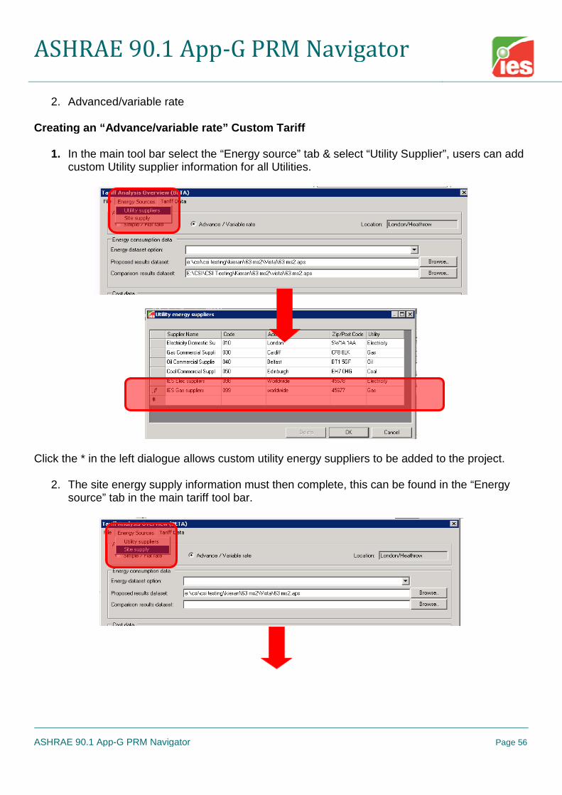
2. Advanced/variable rate
Creating an “Advance/variable rate” Custom Tariff
1. In the main tool bar select the “Energy source” tab & select “Utility Supplier”, users can addcustom Utility supplier information for all Utilities.
Click the * in the left dialogue allows custom utility energy suppliers to be added to the project.
2. The site energy supply information must then complete, this can be found in the “Energysource” tab in the main tariff tool bar.

ASHRAE 90.1 App-G PRM Navigator
ASHRAE 90.1 App-G PRM Navigator Page 57
3. Tariff data must now be created for all required utilities, clicking the “Tariff data” tab in themain tool bar will allow users created the required tariffs.
Users will be presented with a listed of suppliers as per step 1. Tariffs can be added &remove to the supplier tariff template. The below dialogue shows the created utilitycompany in the “supplier” window.
Tariffs can be added to the supplier template by clicking “Add” & naming the tariff. Once thetariff has been added the following information must be set:

ASHRAE 90.1 App-G PRM Navigator
ASHRAE 90.1 App-G PRM Navigator Page 58
Currency Dated created & Tariff type Bills Made
4. Once the above information has been set the detailed “Tariff type” information must be set.Depending on the tariff type selected more icons will become available for example; whenthe “Basic” tariff type is selected two icons appear “standing rate & time of use rates.
Or with “Maximum Demand” tariff type

ASHRAE 90.1 App-G PRM Navigator
ASHRAE 90.1 App-G PRM Navigator Page 59
5. Setting charges
Set basic, standing & Min. Monthly charge as indicated above.
6. Set time of use regimes, detailed variable tariff information can be set here.

ASHRAE 90.1 App-G PRM Navigator
ASHRAE 90.1 App-G PRM Navigator Page 60
MORE DETAIL NEEDED!!
7. Set “Tax/discount” information is required

ASHRAE 90.1 App-G PRM Navigator
ASHRAE 90.1 App-G PRM Navigator Page 61
8. Once the previous steps have been followed the custom tariff data can now be assigned tothe utility types.
First set the “Energy consumption data” users must select the required vista results aps.Files to be used for the cost analysis.
Also set currency type (see above) Set “Cost Analysis” information (assign custom tariff templates as previously created)
ASHRAE 90.1 App-G PRM Navigator
ASHRAE 90.1 App-G PRM Navigator Page 62
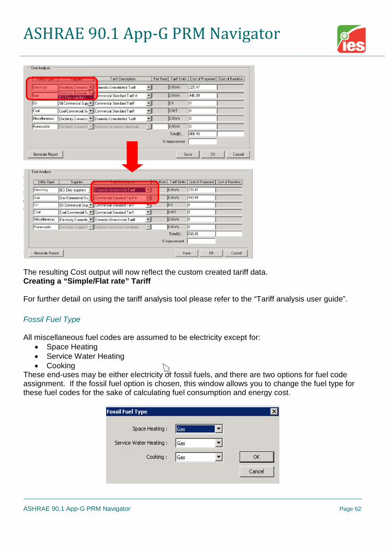
The resulting Cost output will now reflect the custom created tariff data.Creating a “Simple/Flat rate” Tariff
For further detail on using the tariff analysis tool please refer to the “Tariff analysis user guide”.
Fossil Fuel Type
All miscellaneous fuel codes are assumed to be electricity except for: Space Heating Service Water Heating Cooking
These end-uses may be either electricity or fossil fuels, and there are two options for fuel codeassignment. If the fossil fuel option is chosen, this window allows you to change the fuel type forthese fuel codes for the sake of calculating fuel consumption and energy cost.

ASHRAE 90.1 App-G PRM Navigator
ASHRAE 90.1 App-G PRM Navigator Page 63
10.Generate Baseline
Figure 41 - Generate Baseline Tasks
Generate the Baseline Model
This navigator step automatically generates the baseline models & assigns all relevant baselineinformation created in previous navigator steps/stages.
Note: This is a very important step in the navigator workflow as it essentially assigns all modeldata setup in previous navigator steps. If any changes are made to navigator steps after thegeneration of the baseline models, the baseline models must be re-generated in order to assignupdated model data i.e. lighting, ventilation rates, occupancy etc.Baseline sizing runs will also need to be rerun if changes effect space loads i.e. Lighting,ventilation rates, occupancy etc. If data changes post “baseline generation” do not affect spaceloads (i.e. exterior lighting) users must still re-do the following navigator steps “Assign room sizingdata” & “update fan & coil sizing data”.

ASHRAE 90.1 App-G PRM Navigator
ASHRAE 90.1 App-G PRM Navigator Page 64
Once the baseline models have been generated users can toggle between the Proposed &Baseline geometry. See above.
Special Baseline Geometry Edits
It might be necessary to make custom geometry edits to the baseline model due to the ASHRAE90.1 modeling rules. For example if the proposed model has a double skin façade it is requiredthat the baseline model excludes this building feature. The following steps must be followed inorder to make custom edits to the baseline model geometry.
Enter ModelIt and switch to Baseline model by selecting “view” model in the main toolbar.
Delete the double-skin façade geometry from the baseline model.

ASHRAE 90.1 App-G PRM Navigator
ASHRAE 90.1 App-G PRM Navigator Page 65
Return to the BPRM view.
At this point the newly exposed facade will have default VE constructions assigned.You must manually assign the baseline exterior wall constructions for this facade.
Once the facade constructions have been assigned, the 0 deg baseline model geometryand construction assignment should now be correct.
IF after removing the double-skin façade the overall window-to-wall ratio for the entirebaseline building exceeds 40%, the newly exposed glazing on facades where the DSFwas removed will need to be downsized until the overall 40% requirement is met. (If theproposed building had greater than 40% WWR prior to generating the Baseline building,the glazing area on all exterior facades will have been automatically reduced to meet therequirement.)
For user that have previously generated the other baseline orientations by runningRoom Load Calculations after generating the baseline model, these other orientationsmust be refreshed. This is will be dealt with by running the Room Load calculations in alater step. As these other baseline orientations are based on the 0-degree baseline,there will be no need to repeat the steps above.

ASHRAE 90.1 App-G PRM Navigator
ASHRAE 90.1 App-G PRM Navigator Page 66
11.Sizing Runs
Figure 42 - Sizing Runs Sub-categories and Tasks
Room Load CalculationsThis navigator step automatically opens up the ApacheLoads dialog with default informationapplied. The user can edit the information relating to the proposed model. The four baseline runsare generated automatically.

ASHRAE 90.1 App-G PRM Navigator
ASHRAE 90.1 App-G PRM Navigator Page 67
As with a normal ApacheLoads run this will generate information relating to room heating andcooling loads. This information is then used to populate the default PRM sizing sheets located inthe ‘Loads Data’ folder of the project directory. This will generate flowrate data for use in theproposed and baseline HVAC networks.
Assign Room Sizing DataThis step automatically assigns the sizing data generated from the step above to the proposedand baseline HVAC networks.
System Load CalculationsThis navigator step opens up the ApacheLoads dialog again, this time an ApacheHVAC network isassigned in order to enable a system sizing calculation. This will provide information to sizevarious system elements i.e. fan and coil data.

ASHRAE 90.1 App-G PRM Navigator
ASHRAE 90.1 App-G PRM Navigator Page 68
As above, the user can edit the information relating to the proposed model. The four baseline runsare generated automatically.
Update Fan And Coil Sizing DataThis step automatically assigns the sizing data generated from the step above to the proposedand baseline HVAC networks.

ASHRAE 90.1 App-G PRM Navigator
ASHRAE 90.1 App-G PRM Navigator Page 69
Sizing Reports
ProposedThis step enables the generation or display of a system level report for the proposed model. Thereport is broken down into three sections
Project Summary:
Contains information relating to the project area and volume, input data for the sizing calculationsand design weather data.

ASHRAE 90.1 App-G PRM Navigator
ASHRAE 90.1 App-G PRM Navigator Page 70
System Sizing Plant Loads:
Contains information relating to the overall performance of the heating and cooling systems e.g.the system type, the floor area served and peak load occurrence.
System Sizing System Loads:
Contains detailed information relating to performance of each individual system including sizingdata relating to each individual room served by the system.

ASHRAE 90.1 App-G PRM Navigator
ASHRAE 90.1 App-G PRM Navigator Page 71
The report includes data regarding the sizing of the following:
Heating and cooling coils Supply fans Return fans Exhaust fans Outside air ventilation rates Zone heating coils (reheat) Zone airflow rates
The System Sizing report also includes an Engineering Checks section.
Baseline 0°The report contains data relating to the Baseline 0o model sizing runs.
Baseline 90°The report contains data relating to the Baseline 90o model sizing runs.
Baseline 180°The report contains data relating to the Baseline 180o model sizing runs.
Baseline 270°The report contains data relating to the Baseline 270o model sizing runs.
Setting Baseline HVAC/DHW manual inputs
Once sizing runs have been performed & auto-sized data has been assigned to the HVACnetworks users are required to make some manual edits to the baseline HVAC network in order tocomply with ASHRAE 90.1 rules. (These will be autosized/set in future releases).
1. Set baseline “heating source” minimum efficiency. See ASHRAE 90.1 tables 6.8.1A to6.8.1F. The baseline system efficiency is dependent on the heating plant load; users shoulduse the baseline sizing calculations to determine the required efficiency.
2. Number of baseline boilers if systems 1, 5 or 7 are being modeled. See ASHRAE 90.1G3.1.3.2. If two boilers are required the boiler Qrat input must be divided by two.
3. Set baseline hot water pump type i.e. Variable speed or constant speed based as perASHRAE 90.1 section G3.1.3.5.

ASHRAE 90.1 App-G PRM Navigator
ASHRAE 90.1 App-G PRM Navigator Page 72
4. Set chiller plant minimum efficiency as per tables 6.8.1A to 6.8.1F. The baseline systemefficiency is dependent on the cooling plant load; users should use the baseline sizingcalculations to determine the required efficiency.
5. Set number & type (screw or centrifugal) of baseline chillers for systems 7 & 8 as perASHRAE 90.1 table G3.1.3.7.
6. Select chilled water reset as per ASHRAE 90.1 G3.1.3.9 ruling.
7. Set chilled water baseline pump type i.e. Variable speed or constant speed based as perASHRAE 90.1 section G3.1.3.10.
8. Set baseline heat rejection requirements as per ASHRAE 90.1 G3.1.3.11 (system 7 & 8only).
9. Set baseline condenser heat recovery if required as per ASHRAE 90.1 section 6.5.6.2.1.
10. Users are required to manually set the SHW plant efficiency as per section 7 of ASHRAE90.1. The boiler tab in ApHVAC contains a prototype SHW system that should be used forthe baseline SHW. Users will need to tick the “Use for DHW” & open the heat source & setthe required baseline efficiency.
11.Airside economizers need to be engaged for each system air handler, as required byASHRAE 90.1 G3.1.2.6, via the AHU Parameters dialog prior to system autosizing.
12.Exhaust air energy recovery needs to be engaged and appropriate recovery effectivenessset for each system air handler, as required by ASHRAE 90.1 G3.1.2.10, via the AHUParameters dialog prior to system autosizing.
13.DX Cooling autosizing is applied to the DX Coil component and this, by default, is set tooverride the capacity that has been pre-set in the DX Cooling types dialog. This scales theperformance curves in the types dialog as needed to match the size of each DX Coolinginstance for that type. The DX Cooling types are set up to match ASHRAE 90.1 COPvalues (fan-power having been removed from EER values provided in ASHRAE Table6.8.1A, 6.8.1B, and 6.8.1D) for each ASHRAE size range.
For systems 3, 5, and 6, these are dynamically re-assigned as needed to matchappropriate COPs with the sized DX cooling unit.
For systems 1, 2, and 4, until the same level of automation is provided within thesoftware, users will need to manually check within the Cooling Coil dialog and, ifneeded, change the selection of pre-defined DX Cooling Type to match theequipment (PTHP vs. PTAC and PSZ-HP vs. PSZ-AC) and COP for the autosizedcomponent to those in ASHRAE tables 6.8.1B and 6.8.1D). Again, the COP values

ASHRAE 90.1 App-G PRM Navigator
ASHRAE 90.1 App-G PRM Navigator Page 73
for the rated condition in the pre-defined DX Types are based upon the EER valuesfrom the ASHREA tables, with fan power having been removed.
14.Air-Source Heat Pumps in System 2 (PTHP) are set up, by default, with ten COP andcapacity values forming a performance curve in relation to outdoor temperature (ASHRAEvalue at rated condition, sans SA fan power, adjusted according to ASHRAE standardperformance curves and assumed part-load operation above a 32 °F thermal balance point)to match equipment with capacity in the range of 7-15 kBtu/h (2.05-4.4 kW). For PTHPsystems with either lesser or greater capacity, until this is automated in the software, usersmust replace the COP values in the Heat Pump component dialog with the appropriate setfrom Appendix B: HVAC Systems Modeling Guidance Specific to ANSI/ASHRAE/IESNAStandard 90.1-2007 in the ApacheHVAC User Guide. There are just three capacity rangesfor PTHP heating mode COPs in ASHRAE 90.1-2007.
Tip: Select just the multiplex layers with Heat Pump components that have anautosized capacity (value on the 10th row at 47 °F) that is either less than or greaterthan 7-15 kBtu/h (but not both). Then, while in multiplex Global Edit mode, revise theten COP values simultaneously for all of these.
15.Air-Source Heat Pumps in System 4 (PSZ-HP), similar to system-2 heat pumps, are set up,by default, with 10 COP and capacity values forming a performance curve in relation tooutdoor temperature (ASHRAE value at rated condition, sans SA fan power, adjustedaccording to ASHRAE standard performance curves and assumed part-load operationabove a 32 °F thermal balance point) to match equipment with capacity in the range of 65-135 kBtu/h (2.05-4.4 kW). For PSZ-HP systems with either lesser or greater capacity, untilthis is automated in the software, users must replace the COP values in the Heat Pumpcomponent dialog with the appropriate set from Appendix B: HVAC Systems ModelingGuidance Specific to ANSI/ASHRAE/IESNA Standard 90.1-2007 in the ApacheHVAC UserGuide. There are just three capacity ranges for PSZ-HP heating mode COPs in ASHRAE90.1-2007.
Tip: Select just the multiplex layers with Heat Pump components that have anautosized capacity (value on the 10th row at 47 °F) in a capacity range lesser orgreater than 65-135 kBtu/h (but not both) and, while in Global Edit mode, revise theten COP values simultaneously for all of these. If there are Heat Pumps withautosized capacity in a yet another ASHRAE capacity range, change the multiplexlayer selection to include just these layers and repeat the global edit of COP values.
16.For detailed information on baseline HVAC modelling requirements please refer toASHRAE 90.1 section 6 & Appendix G.
Note: For cases where the Proposed SHW & heating plant are served by the same boiler systemthe automatic report generator will not match the vista fuel code results, as certain vista energyresults are post-proceeded in order to separate the SHW & heating fossil fuel loads.

ASHRAE 90.1 App-G PRM Navigator
ASHRAE 90.1 App-G PRM Navigator Page 74
12.Simulations
Figure 43 - Simulations Tasks
Proposed Model SimulationThis step allows the user to set up a full annual simulation for the proposed model. Ensure that thecorrect model links and the correct Apache HVAC file are selected. Ensure that the simulation timeis set from 1st Jan – 31st Dec.
0° Baseline Model SimulationThis step will automatically run a full annual simulation for the 0o baseline model.

ASHRAE 90.1 App-G PRM Navigator
ASHRAE 90.1 App-G PRM Navigator Page 75
Full PRM SimulationThis step will run a full annual simulation for the proposed and all four baseline models. The useris required to set up data relating to the proposed simulation. The four baseline simulations are runautomatically.
Macroflo & the PRM navigator
In order to link the VE Macroflo module into the PRM navigator users must first run the “Full PRMsimulation” with the Macroflo link ticked off. Once the full simulation is complete users must thenrun the “Proposed model simulation” with the Macroflo link ticked on. The proposed simulationmust be run again with the same simulation name so that it over writes the first proposed resultsfile.
13.Cost
Please refer to the tariff analysis tool please refer to the “Tariff analysis user guide”.

ASHRAE 90.1 App-G PRM Navigator
ASHRAE 90.1 App-G PRM Navigator Page 76
14.Results
Figure 44 - Results Navigator Sub-categories and Tasks

ASHRAE 90.1 App-G PRM Navigator
ASHRAE 90.1 App-G PRM Navigator Page 77
Set Parameters For “Unmet Load Hour” Temperature Tests
Section G3.1.2.2 of ASHRAE 90.1 2007 states “Unmet load hours for the proposed design orbaseline building designs shall not exceed 300 (of the 8760 hours simulated), and unmet loadhours for the proposed design shall not exceed the number of unmet load hours for the baselinebuilding design by more than 50. If unmet load hours in the proposed design exceed the unmetload hours in the baseline building by more than 50, simulated capacities in the baseline buildingshall be decreased incrementally and the building re-simulated until the unmet load hours arewithin 50 of the unmet load hours of the proposed design. If unmet load hours for the proposeddesign or baseline building design exceed 300, simulated capacities shall be increasedincrementally, and the building with unmet loads re-simulated until unmet load hours are reducedto 300 or less. Alternatively, unmet load hours exceeding these limits may be accepted at thediscretion of the rating authority provided that sufficient justification is given indicating that theaccuracy of the simulation is not significantly compromised by these unmet loads.”
The “unmet load hours” can be calculated in two different places in the VE:
1. From the PRM navigator “Unmet load hours report”
2. From the Range test dialog in Vista, using the heating & cooling set points, and thelogical “OR” shared hours test. Currently, the user must click “Occupied hours only” aswell.
See below detail for the above two approaches.
PRM Navigator “Unmet load hours”When using the PRM navigator the range of hours tested to meet the unmet load hourrequirements are defined within the “system schedule” dialogue.

ASHRAE 90.1 App-G PRM Navigator
ASHRAE 90.1 App-G PRM Navigator Page 78
If “Apply as the ‘plant profile’ for all rooms” is left as ‘ticked’ then it will create a new annual profilenamed ‘Plant-conditioning times’ which will be assigned as the ‘Plant profile’ for all rooms. Thisprofile will provide just two things to the actual unmet load hours test:
1. The opening hours, and thus a means of shifting the effective times that the times heatingand cooling set points switch from Occ to Nt/Unocc set point values
2. The times for which the HVAC will actually be OFF (it is rare to allow this outside of verymild climates).
In other words, while modelling of the HVAC system operation needs to use the Occ set pointsover the larger number of hours that include warm-up and wind-down, the Unmet Load Hours testneeds to use these more stringent set points over a shorter period of each day (just the openinghours) This test must assume the rest set points to be at the unoccupied values during the warm-up and wind-down. It should stop counting unmet load hours outside of occupied times only whenthe selected Setback Strategy is “HVAC Off”.
Once the above information has been set users are also prompted in a later navigator step to settolerances for the unmet load hour check.

ASHRAE 90.1 App-G PRM Navigator
ASHRAE 90.1 App-G PRM Navigator Page 79
The purpose of these tolerances is to allow for the effect of control bands when reporting unmetload hours. The heating set point tolerance is subtracted from the room heating set point. Thecooling set point is added to the room cooling set point.
Range test dialogue in VistaIt may be necessary to manually check the unmet load hours for models that do not have acommon heating & cooling set point for all model spaces. This means that a manual approachmust be implemented for spaces with common heating & cooling set points. ?This manual approach uses the range test feature within the Vista results analysis tool to performthe unmet load hour’s check. Users must select the required model rooms or groups of rooms theywish to test & then select the range test icon in the main Vista results analysis tool bar. The belowinterface will appear:

ASHRAE 90.1 App-G PRM Navigator
ASHRAE 90.1 App-G PRM Navigator Page 80
Users must select the “when plant conditioned” from the above drop down window & set theheating cooling tolerance ranges before clicking the apply button. Once the “apply” button hasbeen clicked the user will be presented with results.Using this approach means that users will have to manually create the LEED results table 1.3 forsubmittal & that the automated result table 1.3 generated when the reportage button is activated isnow redundant.
BPRM Report
BPRM results are presented in a format similar to the standard LEED letter template.
Initially user specified information is entered.
The Navigator then generates individual tables from within the report. Finally the BPRM report canbe generated in full.
User DetailsInput user details for use in the full BPRM report.
Data For Tables 1.3 and 1.4Certain data relating to tables 1.3 and 1.4 has to be entered manually. Information entered herewill be shown in the full BPRM report.

ASHRAE 90.1 App-G PRM Navigator
ASHRAE 90.1 App-G PRM Navigator Page 81
Cost Savings Summary – Table 1.8.2(b)
Table 1.8.2(b), the cost savings summary table, is presented.
Energy Savings Summary – Table 1.8.2Table 1.8.2, the energy savings summary table, is presented.

ASHRAE 90.1 App-G PRM Navigator
ASHRAE 90.1 App-G PRM Navigator Page 82
Baseline Costs – Table 1.8.1(b)Table 1.8.1(b), the baseline costs table, is presented.
Baseline Energy – Table 1.8.1Table 1.8.1, the baseline energy table, is presented.

ASHRAE 90.1 App-G PRM Navigator
ASHRAE 90.1 App-G PRM Navigator Page 83
Full ReportThe full BPRM report is generated containing all the above tables, plus
Table 1.1 - General Information

ASHRAE 90.1 App-G PRM Navigator
ASHRAE 90.1 App-G PRM Navigator Page 84
Report images can be replaced by:1. Open model viewer2. Adjust the model view accordingly3. Save the image to the VISTA BPRM folder with the project Vista file, over write appropriate
default BMP default file & regenerate report.

ASHRAE 90.1 App-G PRM Navigator
ASHRAE 90.1 App-G PRM Navigator Page 85
4. Table 1.2 – Space Summary
Table 1.3 – Advisory Messages

ASHRAE 90.1 App-G PRM Navigator
ASHRAE 90.1 App-G PRM Navigator Page 86
Table 1.4 – Comparison of Proposed versus Baseline Design

ASHRAE 90.1 App-G PRM Navigator
ASHRAE 90.1 App-G PRM Navigator Page 87
Table 1.5 – Energy Type Summary
Table 1.6 – On Site Renewable Energy

ASHRAE 90.1 App-G PRM Navigator
ASHRAE 90.1 App-G PRM Navigator Page 88
Table 1.7 - Exceptional Calculation Methods

ASHRAE 90.1 App-G PRM Navigator
ASHRAE 90.1 App-G PRM Navigator Page 89
Detailed Simulation Reports
ProposedThis step enables the generation or display of the 10 minute checklist report for the proposedmodel. The report contains four separate sections.
Building Utility Performance Table:
This table details the utility breakdown for each of the end use categories associated with the PRManalysis and includes electricity, fossil fuels and any renewables.
The report also displays the total energy associated with electricity and fossil fuels.
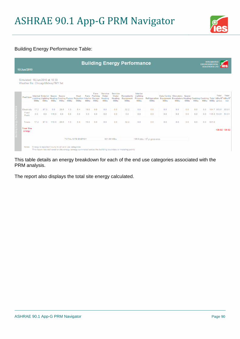
ASHRAE 90.1 App-G PRM Navigator
ASHRAE 90.1 App-G PRM Navigator Page 90
Building Energy Performance Table:
This table details an energy breakdown for each of the end use categories associated with thePRM analysis.
The report also displays the total site energy calculated.

ASHRAE 90.1 App-G PRM Navigator
ASHRAE 90.1 App-G PRM Navigator Page 91
Building Energy & End Use Summary Table - Electricity:
This table shows a detailed breakdown of the monthly performance of each of the PRM end usecategories for all electric meters.
The annual electricity energy is also shown for each end use and summed to give the total annualelectrical energy.
Note: The total column in this report may not be the sum of end uses; any excess generatedelectricity (negative total) is assumed to be exported

ASHRAE 90.1 App-G PRM Navigator
ASHRAE 90.1 App-G PRM Navigator Page 92
Building Energy & End Use Summary Table – Fossil Fuel:
This table shows a detailed breakdown of the monthly performance of each of the PRM end usecategories for all fossil fuel meters. The annual fossil fuel energy consumption is also shown foreach end use and summed to give the total annual fossil fuel energy consumption.
Baseline 0°This enables generation or display of the Detailed Simulation Report for the baseline 0o model.
Baseline 90°This enables generation or display of the Detailed Simulation Report for the baseline 90o model.
Baseline 180°This enables generation or display of the Detailed Simulation Report for the baseline 180o model.
Baseline 270°This enables generation or display of the Detailed Simulation Report for the baseline 270o model.

ASHRAE 90.1 App-G PRM Navigator
ASHRAE 90.1 App-G PRM Navigator Page 93
ASHRAE 62.1
Display Selected Reports
This action provides for the selection and display BPRM Reports for individual PRM runs(proposed plus four baselines), if multiple simulation runs have been performed. For example, youmay have run a number of scenarios to be compared or may have completed a separate run as anExceptional Calculation Method or with renewable energy systems added, etc. that will beseparately reported in the submittal.
Additional Documentation of VE Results for LEED EA credit 1 submittal
The majority of the data needed for the LEED submittal is included in the BPRM Reports, DetailedSimulation Reports, and ASHRAE 62.1 ventilation report described above. It may be desirable toinclude additional documentation, such as the System Sizing reports as introduced in the SizingRuns section of this user guide.
When you complete the Room Loads Calculation step in either the System Prototypes &Sizing or PRM Navigator, this generates a loads report. It is best to use the reportgenerated at the time of the loads run used for sizing of zone airflows, etc. If the ConductionGains Breakdown and other internal gains breakdowns are checked in the Output Optionsdialog within ASHRAE Loads, then that data will be recorded for query in Vista Results andfor display in the loads report.
o When running ASHRAE Loads, the recommended Simulation Options for achievinga high level of accuracy in results are as follows: External convection model: McAdams (this model varies the convection
coefficients with wind speed and surface-to-air delta-T) Internal convection model: Alamdari & Hammond (this model varies the
convection coefficients with surface-to-air delta-T)
o The suggested Output Options for detailed documentation are as follows:
o To have the loads report include detailed results for each zone or separate space inthe model (including UFAD plenums, occupied zones, stratified zones, etc.), once inVista Results and prior to clicking the report generator button on the toolbar, you willneed to go to Report Preferences on the Settings menu and select Detailed roomloads. This will add a report section for each space.
When you complete the System Load Calculations step in either the System Prototypes &Sizing or PRM Navigator, this will then generate a similar report for each space, this timeincluding much more information about the actual loads and flow rates, etc. for each zoneas seen by the actual system at the time of sizing. The following is an example of onesystem section and one zone section of from this report. Note that presently, this system

ASHRAE 90.1 App-G PRM Navigator
ASHRAE 90.1 App-G PRM Navigator Page 94
sizing report can be generated and displayed only via one of the two workflow navigatorsnamed above. As of VE 6.4, this will also be generated by a sizing run initiated from withinApacheHVAC and accessed directly from the Vista Results viewer.

ASHRAE 90.1 App-G PRM Navigator
ASHRAE 90.1 App-G PRM Navigator Page 95

ASHRAE 90.1 App-G PRM Navigator
ASHRAE 90.1 App-G PRM Navigator Page 96

ASHRAE 90.1 App-G PRM Navigator
ASHRAE 90.1 App-G PRM Navigator Page 97
Note that for non-standard systems and equipment, certain plant items may not show up in theSystem Sizing reports above, as they are not dealt with in the same manner as other morestandard equipment. For example, if an Indirect-Direct Evaporative Cooling system is used in theproposed design, the cooling section of this actually consists of a couple spray chambers, a heatexchanger, a bypass damper or two, and controllers for the target leaving conditions. As there aremany ways to set this up, size the components, and control the cooling effect, this does not lenditself to autosizing per se, nor are there appropriate values to report as would otherwise be thecase for a cooling coil or chiller. For example, in the case of capability for a spray chamber toachieve the maximum saturation performance of the selected unit (e.g., 84% effectiveness), thenormal configuration would allow the spray chamber to add as much water to the airstream asrequired to achieve this level of performance. It is then up to the engineer to ensure that the actualselected unit can achieve this at the design cooling conditions, including entering air conditionsand flow rates.

ASHRAE 90.1 App-G PRM Navigator
ASHRAE 90.1 App-G PRM Navigator Page 98

ASHRAE 90.1 App-G PRM Navigator
ASHRAE 90.1 App-G PRM Navigator Page 99
Section 1.4 Proposed vs. Baseline Constructions in the BPRM Reports will provide most of thenecessary documentation (as shown above) for these aspects of the modeling. However, someusers may wish to provide additional supporting detail regarding constructions.
For example, it might be desirable to make a list of the constructions used in the model, then pastein screen captures, such as that shown below, for each of these constructions (e.g., if you want toinclude the ASHRAE U-value calculations (which use ASHRAE rather than CIBSE or ISO valuesfor indoor and outdoor temperatures and air-film resistance).
It may then be helpful to copy the image of the building with red highlights from the ConstructionAssignment dialog (use the Copy button) and paste this in to show where in the model eachconstruction type has been applied. An example of this is included below. The copy of this imagealso comes with a text version of the contents of the dialog above; however, this includes only theCIBSE and ISO U-values. While these can be forced to match the ASHRAE values by fixing theinside and outside air-film resistances at the ASHRAE values in the construction, doing so willnegate the effect of variable convective heat transfer coefficients if they are selected for thesimulation (in the ApacheSim dialog).

ASHRAE 90.1 App-G PRM Navigator
ASHRAE 90.1 App-G PRM Navigator Page 100
DESIGN Ext Wall R-21.45Reference ID: STD_WAL6Construction is a from the project database
Layer Description Thickness Conductivity Density Capacity Resistance Vapour res.ft Btu·in/h·ft²·°F lb/ft³ Btu/lb·°F ft²·h·°F/Btu (perm·in)^-1
FACE BRICK - BK04 0.3281 9.083 130.0 0.2 0.0361INSULATED STEEL STUD CAVITY OC 16 (ASHRAE) 0.0833 0.650 1.9 0.2 0.1282FELT & MEMBRANE - FELT - HF-E3 0.0008 1.317 70.0 0.4 0.0006CELLULAR POLYISOCYANURATE - (ASHRAE) 0.1667 0.170 2.0 0.2 0.9804BATT INSULATION (ASHRAE) 0.5000 0.845 2.0 0.2 0.5917GYPSUM/ PLASTER BOARD - HF-E1 (ASHRAE) 0.0517 1.116 50.0 0.2 0.0463
Inside Surface 0.680Outside Surface 0.170Total Resistance 2.633CIBSE Net U-Value Btu/h·ft²·°F 0.0449EN-ISO U-Value Btu/h·ft²·°F 0.0447Outside surface absorptance 0.7000Inside surface absorptance 0.5500Inside Emissivity 0.9000Outside Emissivity 0.9000

ASHRAE 90.1 App-G PRM Navigator
ASHRAE 90.1 App-G PRM Navigator Page 101
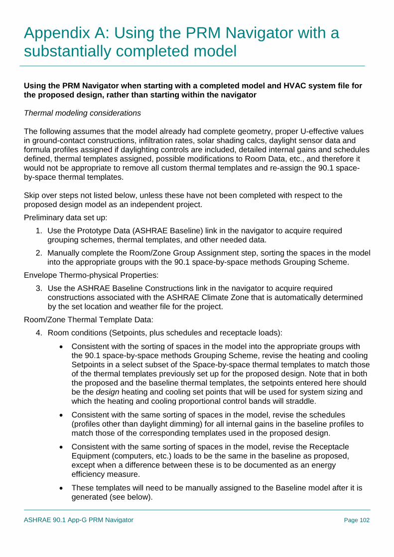
Appendix A: Using the PRM Navigator with asubstantially completed model
ASHRAE 90.1 App-G PRM Navigator Page 102
Using the PRM Navigator when starting with a completed model and HVAC system file forthe proposed design, rather than starting within the navigator
Thermal modeling considerations
The following assumes that the model already had complete geometry, proper U-effective valuesin ground-contact constructions, infiltration rates, solar shading calcs, daylight sensor data andformula profiles assigned if daylighting controls are included, detailed internal gains and schedulesdefined, thermal templates assigned, possible modifications to Room Data, etc., and therefore itwould not be appropriate to remove all custom thermal templates and re-assign the 90.1 space-by-space thermal templates.
Skip over steps not listed below, unless these have not been completed with respect to theproposed design model as an independent project.
Preliminary data set up:
1. Use the Prototype Data (ASHRAE Baseline) link in the navigator to acquire requiredgrouping schemes, thermal templates, and other needed data.
2. Manually complete the Room/Zone Group Assignment step, sorting the spaces in the modelinto the appropriate groups with the 90.1 space-by-space methods Grouping Scheme.
Envelope Thermo-physical Properties:
3. Use the ASHRAE Baseline Constructions link in the navigator to acquire requiredconstructions associated with the ASHRAE Climate Zone that is automatically determinedby the set location and weather file for the project.
Room/Zone Thermal Template Data:
4. Room conditions (Setpoints, plus schedules and receptacle loads):
Consistent with the sorting of spaces in the model into the appropriate groups withthe 90.1 space-by-space methods Grouping Scheme, revise the heating and coolingSetpoints in a select subset of the Space-by-space thermal templates to match thoseof the thermal templates previously set up for the proposed design. Note that in boththe proposed and the baseline thermal templates, the setpoints entered here shouldbe the design heating and cooling set points that will be used for system sizing andwhich the heating and cooling proportional control bands will straddle.
Consistent with the same sorting of spaces in the model, revise the schedules(profiles other than daylight dimming) for all internal gains in the baseline profiles tomatch those of the corresponding templates used in the proposed design.
Consistent with the same sorting of spaces in the model, revise the ReceptacleEquipment (computers, etc.) loads to be the same in the baseline as proposed,except when a difference between these is to be documented as an energyefficiency measure.
These templates will need to be manually assigned to the Baseline model after it isgenerated (see below).

Appendix A: Using the PRM Navigator with asubstantially completed model
ASHRAE 90.1 App-G PRM Navigator Page 103
5. Exterior Lighting: Complete this step. The exterior lighting will be assigned to the last spaceon the Rooms list. While these lights will consume energy, there will be no gains to thespace to which they are assigned.
6. Elevators: Use this step to add elevator energy consumption if appropriate and not yetincluded. Again, this will be assigned to the last space in the Rooms list. If elevators havealready been included, this tool and the associated schedules that come with the PRMPrototype Data may be of use for improving the representation of elevator use.
7. Service Hot Water (DHW): The consumption rate(s) will have to be defined in one or moreof the baseline thermal templates to match that of the proposed design model. Note that asof VE 6.1.1, users can select an independent profile for the consumption pattern (rather tantyping this to occupancy) and can thus put all DHW consumption in one profile for onespace or space type, such as a restroom. When the independent profile is selected, theinput changes from gallons per hour per person to simply gallons per hour. Whichevermethod is used, the baseline and proposed will need to be consistent. Also, note that is theproposed design model links the DHW loads to a boiler in ApacheHVAC, the same shouldbe done for the baseline model.
ApacheHVAC System set up, loads, and sizing
The following assumes the starting point stated above and that ApacheHVAC system file waspreviously completed using the System Prototypes & Sizing navigator or similar VE features, andthat this included the implementation of ASHRE 62.1 ventilation rates, if appropriate, via thespreadsheet. Given this, it is assumed that all system sizing has been completed and there areassociated Loads Data spreadsheets that have already been generated for each system in the“proposed.asp” file.
8. Make backup copies of both the proposed HVAC system file and the associated LoadsData spreadsheets.
9. Use Edit Current Baseline to open the baseline prototype systems file, choose and copy asneeded the appropriate baseline system types, delete unneeded systems.
10.While the Baseline.asp system is open, complete the assignment of spaces in the model tolayers in the multiplex using the Assign from Room Group, as was very likely donepreviously for the proposed design.
11.AHU Parameters: This step will create Loads Data spreadsheets for each of the baselinesystems in the Baseline.asp file and provides the opportunity to set any variance fromdefault values for basic parameters. For example, if the ASHRAE requirement for thebaseline system outside air economizer high-limit is 75, set this up to 75 from 70 for allsystems to which it applies. Revise the AHU cooling coil LAT values so as to be 20 F belowthe space design cooling setpoint.
12.Again, it is assumed here that the proposed system has previously been set up, scheduled,sized, and tested. If this was completed using the System Prototypes & Sizing navigator orequivalent tools in the VE, the System Schedules dialog should already have been used toset values in the pre-defined system profiles accordingly.

Appendix A: Using the PRM Navigator with asubstantially completed model
ASHRAE 90.1 App-G PRM Navigator Page 104
13.Other Input Data: Complete set up of Renewable Energy Systems and Utility Tariffs asappropriate.
14.Generate the baseline model.
15.Check for proper set up of ground-contact constructions with a U-effective adjustment layer,reduction of overall glazing area (if the proposed design has more than 40% of the overallwindow-to-wall ratio for the entire building—not per facade—the glazing should have beenreduced to 40%), and so forth.
16.For users with UFAD and DV systems or other thermally stratified environments in theproposed design, this is the time to remove the partitions with holes that separate occupiedand stratified zones (or the potentially multiple sub-zones in an atrium that is meant tostratify).
17. If the proposed design model has a double-skin façade, this should also be removed at thistime, as follows:
Enter ModelIt and switch to Baseline model.
Delete the double-skin façade geometry from the baseline model.
Return to the BPRM view.
At this point the newly exposed facade will have default VE constructions assigned.You must manually assign the baseline exterior wall constructions for this facade.
Once the facade constructions have been assigned, the 0 deg baseline model geometryand construction assignment should now be correct.
IF after removing the double-skin façade the overall window-to-wall ratio for the entirebaseline building exceeds 40%, the newly exposed glazing on facades where the DSFwas removed will need to be downsized until the overall 40% requirement is met. (If theproposed building had greater than 40% WWR prior to generating the Baseline building,the glazing area on all exterior facades will have been automatically reduced to meet therequirement.)
For user that have previously generated the other baseline orientations by runningRoom Load Calculations after generating the baseline model, these other orientationsmust be refreshed. This is will be dealt with by running the Room Load calculations in alater step. As these other baseline orientations are based on the 0-degree baseline,there will be no need to repeat the steps above.
18.While in the BPRM view, select Baseline (vs. Proposed) from the drop-down menu on thetoolbar. Then manually assign the 90.1 Space-by-space thermal templates to the baselinezones consistent with the sorting of spaces in the model into the appropriate groups withthe 90.1 space-by-space methods Grouping Scheme. The grouping will allow efficientselection of multiple zones to which the same template is to be assigned.
19.Go to the Loads Data folder in the Project folder and open the spreadsheets in both theProposed folder and the Baseline0 folder in matched pairs (one from each folder) forcomparison.

Appendix A: Using the PRM Navigator with asubstantially completed model
ASHRAE 90.1 App-G PRM Navigator Page 105
20.Duplicate any changes in the changes previously made in the proposed sys spreadsheets,such as ACH rates and 100% transfer air designations for exhausted restrooms on theRoom Design Airflows tab, and the space types on the 62.1 ventilation tab (if used) to thebaseline version of each spreadsheet. Note that some things here will be specific to theproposed system, such as ventilation effectiveness or any departure from typical supply airtemperatures, and should not be duplicated in the corresponding baseline systemspreadsheets.
21.Close any spreadsheets for proposed systems that are still open.
22.Open all baseline system spreadsheets residing in the Baseline0 folder (the ones thatwould have been edited in the previous step above).
23.Calculate the baseline fan-power adjustment value for “A” according to ASHRAE 90.1section 6.5.3.1.1—taking credit for ducted returns, MERV-13 filtration, energy recoverydevices, direct evaporative cooling, etc.—as in the example below. Enter this value for “A”into the green cell under Baseline Fan Curve User Inputs on the appropriate Sys tab (forthe baseline system number) in all spreadsheets in the Baseline0 folder, as appropriate.For example, the entry cell is U24 on the Sys 5,7 tab is this pertains to Baseline Systemtype 5 or 7.
A = sum of (PD × CFMD/4131)
where
PD = each applicable pressure drop adjustment in i.w.c. from Table 6.5.3.1.1B
CFMD = the design airflow (i.e., from the actual design) in CFM through eachapplicable device (from Table 6.5.3.1.1B)
Example: If AHU-1 has a MERV 13 filter and a Heat recovery device with design staticpressure of 1.2 i.w.c, both at a design flow rate of 20,000 cfm, then...
A = (0.9*20,000/4134) + (1.2*20,000/4134) = 10.2
Note that because the adjustments are relative to the design condition in the proposedsystem, these calculations can be performed prior to sizing the baseline systems. However,the spreadsheet still needs the results of the baseline system sizing to complete itscalculation of the final fan efficiency values.
Entering a number in the spreadsheet for “A” will revise the fan efficiency for each of thefive data points for Fan component (e.g., SA fan component S2 on the Sys 5,7 tab, ashighlighted in the S2 table from that tab below). The static pressure values for the baselinesupply fans will remain unchanged (e.g., at 2.0 i.w.c.). Because TSP is held constant in thiscalculation, and because the baseline SA fan power is accounting for ALL fans, other thanparallel fan-powered boxes, in the baseline system, the resulting efficiency values willappear remarkably low, as in this example:

Appendix A: Using the PRM Navigator with asubstantially completed model
ASHRAE 90.1 App-G PRM Navigator Page 106
24.Close ALL spreadsheets.
25.Copy ALL revised spreadsheets in the Baseline0 folder to the other three Baseline LoadsData folders (Baseline90, Baseline180, Baseline 270).
26.Execute the Room Loads Calculation step. This will populate the spreadsheets.
27.Assign Room Sizing Data: Ensure that you did indeed make a backup copy of“proposed.asp” prior to executing the Assign Room Sizing Data step, which will populatethe controllers in the systems with values form the spreadsheets (you will need this to occurfor all baseline system, but presumably do not need it and very likely do not want it for theproposed system).
28.System Load Calculation: The dialog should have “proposed.asp” set as the linked HVACfile. This will then run five times automatically—one for the proposed and four more for thefour Baseline systems.
29.For VE 6.1 through 6.2 and all intermediate versions, RATHER than proceeding to the nextstep, side-step a bug in this by manually transferring the final Fan efficiency values, asfollows:
The bug, which has been fixed for VE 6.2.1, writes the system re-heat coil sizes tothe spreadsheet in the incorrect rows. Thus users of version prior to 6.2.1 shouldavoid using the “Update fan and coil sizing data” step in the navigator. Instead...
Manually copy the revised efficiency values (after system sizing) from the Fan CurveDetails for S2 table, as highlighted in the example above, to the corresponding S2fan components in each of the four baseline systems (0, 90, 180, and 270). Note thatthis cannot properly be done prior to system sizing, as the calculation of these valuesdepends upon the flow rates determined in the sizing (which determine the motorefficiency at design flow as selected automatically by the spreadsheet from a table ofASHRAE values for this parameter).
30. In VE 6.2.1 or newer versions, Update fan and coil sizing data will copy the revised fanefficiency values from the spreadsheets to the baseline systems. Again, these arecalculated using a combination of values form the System Loads sizing run, the value for“A” that you calculated and entered, and values for motor efficiency at the design(autosized) flow rate from a lookup table that related motor size and efficiency, perASHRAE 90.1.

Appendix A: Using the PRM Navigator with asubstantially completed model
ASHRAE 90.1 App-G PRM Navigator Page 107
31.Having completed the step above, you should now have ready-to-use baseline systems.You may want to review the System Sizing Reports at this time.
32.As the fan data in the proposed.asp system file will have been altered by the above (whichyou probably didn’t require if this was already set up properly), you will need to open themost recent HVAC system backup file and Save As “proposed.asp” before proceedingfurther. This simply resets proposed.asp back to the fully custom-built version.