navigator troubleshooting guide - duke university · capacitors inside the instrument may still be...
TRANSCRIPT

Navigator ADCP/DVL Troubleshooting Guide
P/N 957-6178-00 (September 2001)
RD Instruments Acoustic Doppler Solutions


Table of Contents 1 Introduction....................................................................................................................................... 1
1.1 Equipment Required ...........................................................................................................................2 1.2 Basic Steps in Troubleshooting...........................................................................................................3
2 Troubleshooting the Navigator ....................................................................................................... 3 2.1 Troubleshooting Safety .......................................................................................................................4 2.2 Troubleshooting a Communication Failure..........................................................................................5
2.2.1 Incorrect Wakeup Messages...............................................................................................................6 2.2.2 Check the Power.................................................................................................................................6 2.2.3 Check the I/O Cable............................................................................................................................6 2.2.4 ADCP/DVL Checks .............................................................................................................................7
2.3 Troubleshooting a Built-In Test Failure ...............................................................................................8 2.3.1 When to use the Spare Boards Kit......................................................................................................8
2.4 Troubleshooting a Beam Failure .......................................................................................................10 2.5 Troubleshooting a Sensor Failure .....................................................................................................11
2.5.1 Fault Log...........................................................................................................................................11 2.6 Technical Support .............................................................................................................................12
3 Navigator Cables ............................................................................................................................ 12 4 System Overview ............................................................................................................................ 15
4.1 Operating Modes ..............................................................................................................................15 4.1.1 Command Mode ...............................................................................................................................15 4.1.2 Ping Mode.........................................................................................................................................16
4.2 Overview of Normal Navigator Operation..........................................................................................17 4.3 Functional Description of Operation..................................................................................................18
4.3.1 Input Power.......................................................................................................................................18 4.3.2 Board Descriptions............................................................................................................................18 4.3.3 Sensors.............................................................................................................................................19
List of Figures Figure 1. Navigator I/O Cable Wiring............................................................................................ 13 Figure 2. Navigator Internal I/O Cable (End-Cap to PIO Board) Wiring........................................ 13 Figure 3. Optional External Battery Pack “Y” Cable ..................................................................... 14 Figure 4. Optional External Battery Case Internal Wiring ............................................................. 14 Figure 5. Optional RS232-to-RS422 Converter Wiring (25-Pin to 9-Pin) ...................................... 15 Figure 6. Navigator Wake-up and Timer Logic ............................................................................. 20 Figure 7. Navigator DC Power Path ............................................................................................. 21 Figure 8. Navigator Block Diagram............................................................................................... 22 Figure 9. Navigator PC Board Locations ...................................................................................... 23
List of Tables Table 1: List of Least Replaceable Assemblies............................................................................. 1 Table 2: Required Test Equipment ................................................................................................ 2 Table 3: Pre-deployment Test (PA) Possible Cause of Failures .................................................. 10

NOTES
Navigator Troubleshooting Guide
P/N 957-6178-00 (September 2001) page 1
Acoustic Doppler Solutions
Navigator Troubleshooting Guide
1 Introduction Considering the complexity of the Navigator, we have provided as much information as practical for field repair; fault location to the component level is beyond the scope of these instructions. The provided information assumes that faults are isolated with a large degree of certainty to a Least Replaceable Assembly (LRA) level only. The time to repair the system will be minimized if an entire replacement unit is available in the field. If time to repair is of essence, RD Instruments strongly advises the availability of the listed LRAs.
Table 1: List of Least Replaceable Assemblies LRA Description
ADCP/DVL The entire ADCP/DVL; includes the electronics, housing, trans-ducer ceramic assemblies, and end-cap.
ADCP/DVL electronics The spare boards kit Includes the PIO, CPU, and DSP boards.
End-Cap Includes the end-cap, connector, and internal I/O cable.
I/O Cable Connects the ADCP/DVL to the Computer.
PC Card Replaceable PC recorder card (optional).
Since these Least Replaceable Assemblies are manufactured in different configurations, please contact RD Instruments (see “Technical Support,” page 12 for contact information) to obtain the correct part number for your specific system configuration. When contacting RD Instruments about a replacement assembly, please provide the serial numbers of the ADCP/DVL. If you want to replace the I/O Cable only, then please provide the cable length.

Navigator Troubleshooting Guide
page 2 RD Instruments
1.1 Equipment Required Special test equipment is not needed for trouble shooting and fault isolation. The required equipment is listed in Table 2. Any equipment satisfying the critical specification listed may be used.
Table 2: Required Test Equipment Required Test Equipment Critical Specification
DMM Resolution: 3 ½ digit
DC-Voltage Range: 200 mV, 2V, 20 V, 200V
DC-Voltage Accuracy: ± 1%
AC-Voltage Range: 200 V, 450 V
AC-Voltage Accuracy: ± 2%
Resistance Range: 200, 2 k, 20 k, 200 k, 20 MOhm
Res.-Accuracy: ± 2% @ 200 Ohm to 200 kOhm
Res.-Accuracy: ± 5% @ 20 Mohm
Capacitance Range: 20 nF, 2 uF, 20 uF
Capacitance Accuracy: ± 5%
Serial Data EIA Break-Out Box such as from Interna-tional Data Sciences, Inc. 475 Jefferson Boulevard Warwick, RI 02886-1317 USA.
Model 60 or similar is recommended as it eases the troubleshooting of RS-232 communication problems significantly. Other manufacturers or models may be substituted.
NOTE. The EIA Break-out Panel is not necessary, but eases RS-232 communication problems troubleshooting significantly.
Navigator Troubleshooting Guide
P/N 957-6178-00 (September 2001) page 3
1.2 Basic Steps in Troubleshooting The first step in troubleshooting is determining what type of failure is oc-curring. There are four types of failures:
• Communication failure
• Built-In test failure
• Beam failure
• Sensor failure Communication failures can be the hardest problem to solve as the problem can be in any part of the system (i.e. the computer, Navigator, cable, or power). The symptoms include having the system not respond, or not re-sponding in a recognizable manner (for example “garbled” text).
Built-In test failures will appear when the system diagnostics are run. Use DumbTerm to identify the failing test.
Beam failures can be identified when collecting data or during the user-interactive performance tests.
Sensor failures can also be identified when collecting data or during the user-interactive performance tests. The sensor may send incorrect data, or not be identified by the system.
2 Troubleshooting the Navigator Although the Navigator is designed for maximum reliability, it is possible for a fault to occur. This section explains how to troubleshoot and fault isolate problems to the Least Replaceable Assembly level (see Table 1, page 1). Before troubleshooting, review the procedures, figures, and tables in this guide. Also, read the “System Overview,” page 15 to understand how the Navigator processes data.
CAUTION. Under all circumstances, follow the safety rules listed in the “Troubleshooting Safety,” page 4.

Navigator Troubleshooting Guide
page 4 RD Instruments
2.1 Troubleshooting Safety Follow all safety rules while troubleshooting.
CAUTION. Servicing instructions are for use by service-trained personnel. To avoid dangerous electric shock, do not perform any service unless qualified to do so.
CAUTION. Complete the ground path. The power cord and the outlet used must have functional grounds. The power plug on the AC power adapter must only be inserted in a socket outlet provided with a protective earth contact. The protective action must not be negated by the use of an extension cord (power cable) without a protective conductor (grounding). Grounding one conductor of a two-conductor outlet is not sufficient protection.
CAUTION. Any interruption of the earthing (grounding) conductor, inside or outside the instrument, or disconnecting the protective earth terminal will cause a potential shock hazard that could result in personal injury.
CAUTION. Only fuses with the required rated current, voltage, and specified type must be used. Do not repair fuses or short circuit fuse-holders. To do so could cause a shock or fire hazard.
CAUTION. Do not install substitute parts or perform any unauthorized modifications to the instrument.
CAUTION. Measurements described in the manual are performed with power supplied to the instrument while protective covers are removed. Energy available at many points may, if contacted, result in personal injury.
CAUTION. Do not attempt to open or service the power supply.
CAUTION. Any maintenance and repair of the opened instrument under voltage should be avoided as much as possible, and when inevitable, should be carried out only by a skilled person who is aware of the hazard involved.
CAUTION. Capacitors inside the instrument may still be charged even if the instrument has been disconnected from its source of power.

Navigator Troubleshooting Guide
P/N 957-6178-00 (September 2001) page 5
2.2 Troubleshooting a Communication Failure Navigator ADCP/DVLs communicate by means of two serial communica-tion channels. The user can choose between RS-232 and RS-422 classes of serial interfaces with a switch on the PIO board in the Navigator.
To successfully communicate, both the host computer and the Navigator must communicate using the same class of serial interface. Standard serial interfaces in IBM compatible computers are also RS-232.
NOTE. If you have just received your Navigator from RDI, the standard configuration is RS-232.
NOTE. If you are using a high baud rate and/or a long I/O cable (greater then 50 meters), RS-232 may not work. Switch to RS-422 and try to wakeup the Navigator again.
There are two types of communication failures; nothing happens at all when attempting to wake up the ADCP/DVL, or something happens, but not the correct wake up message is displayed. Incorrect Wakeup Message
When you send a break and the data is garbled, you may have a baud rate or parity mismatch between the Navigator and the computer, or the Navigator may be set for RS-422 instead of RS-232. Check the RS-232/422 switch on the PIO card inside the Navigator. See “Incorrect Wakeup Messages,” page 6 for symptoms of garbled wakeup messages.
NOTE. Most communication problems are associated with incorrect cabling (i.e. the serial cable is connected to the wrong port) or data protocols (i.e. the wrong baud rate is set between the Navigator and the computer).
Nothing Happens
If you cannot talk to the Navigator (i.e., no wakeup message at all), you need to isolate the problem to a computer fault, power, cable failure, or a Navigator problem. Check the following items:
a. Connect the Navigator to a computer according to the Navigator User’s Guide. Check that all cable connections are tight.
b. Is the Navigator AC power adapter working? Is the input voltage be-tween 100 to 240 VAC? Is the output level 24 VDC?
c. If the Navigator is running from the optional external battery, check that the battery voltage is above 30 Volts DC. Navigator ADCP/DVLs will work at 20 volts; however, both lithium and alkaline battery packs with voltages below 30 volts are at or near their end of life, and are approach-ing uselessness.

Navigator Troubleshooting Guide
page 6 RD Instruments
d. Is the computer hooked up properly? Does it have power?
e. Make sure that your computer and the DumbTerm program are set up to use the communication port the I/O cable is connected to on the com-puter.
2.2.1 Incorrect Wakeup Messages The following conditions may indicate a communications mismatch or lost boot code.
• Sending a break causes “garbage” to appear on the screen. The “garbage” text may keep scrolling. This happens when the com-puter is using RS-232 and the ADCP/DVL is set for RS-422 or vice-versa. Check the RS-232/RS-422 switch on the PIO board (see the Maintenance guide).
• Sending a break causes “garbage” to appear on the screen. You can hear the ADCP/DVL “beep” when the break is sent. The “garbage” text does not keep scrolling. Check that the ADCP/DVL and computer are both using the same baud rate. See the CB-command in the Command and Output Data Format book.
• If the ADCP/DVL gives a steady “beep” when power is applied, the “>” prompt appears on the screen, and a “X” appears when additional breaks are sent, this may indicate that the boot code has been lost (see “ADCP/DVL Checks,” page 7). This can happen if you abort while downloading new firmware. Try downloading the firmware again.
2.2.2 Check the Power The following test can be done with a voltmeter to check the power.
Check the power going into the ADCP/DVL by measuring the voltage on the end of the cable that connects to the Navigator at Pins 3 and 7 (GND) (see “Navigator Cables,” page 12). The voltage should be +24 VDC (using the standard AC adapter). If not, check the voltage at the other end of the cable, and the AC adapter.
2.2.3 Check the I/O Cable This test will check the communication between the computer and the Navigator.
a. Disconnect both ends of the cable and measure the continuity using a DMM (see “Navigator Cables,” page 12 for the wiring diagram). Cor-rect any problems found.

Navigator Troubleshooting Guide
P/N 957-6178-00 (September 2001) page 7
a. Reconnect the I/O cable to host computer.
a. Load DumbTerm on your computer. Select the proper communications port (see the RDI Tools User's Guide for help on using DumbTerm).
b. For RS-232 communications, short pins 1 and 2 together on the female 7-pin connector that was plugged into the Navigator (see “Navigator Cables,” page 12). If you are using RS-422, connect a jumper between pin 2 to pin 6 and another jumper between pins 1 to pin 5 of the under-water connector at the Navigator end of the cable.
c. Type any characters on the keyboard. The keys you type should be ech-oed on the screen. If you see characters, but not correctly (garbage), the cable may be too long for the baud rate. Try a lower baud rate. If this works disconnect the jumper on pins 1 and 2 and then push any keys on the keyboard. You should NOT see anything you type.
d. If the keys are echoed correctly on the screen, the computer and the communication cable are good. Re-connect the I/O cable to the Naviga-tor. The above loop-back test does not show if transmit and receive pairs are interchanged. Thus, it is important that you check the wiring diagrams provided in “Navigator Cables,” page 12.
NOTE. A loop-back test does not show if transmit and receive wires or pairs are interchanged, even though characters may be displayed correctly.
2.2.4 ADCP/DVL Checks Once you have eliminated possible problems with the power, I/O cable, communications settings, and the computer, that leaves the ADCP/DVL as the source of the problem. The following checks may help in some situa-tions. Cold Start the ADCP/DVL
a. Remove the housing to gain access to the PC boards.
b. Remove all power to the ADCP/DVL.
CAUTION. Disconnect the power cables P1 and P2 on the PIO board to ensure that NO POWER is applied to the ADCP/DVL during the next step.
c. Short TP3 to TP4 on the PIO board for 10 seconds.
d. Remove the jumper.
e. Reconnect power cable P1 and P2.
f. Connect the computer and power to the ADCP/DVL. Send a break to the ADCP/DVL. This should start the ADCP/DVL in the “cold start” mode.
Navigator Troubleshooting Guide
page 8 RD Instruments
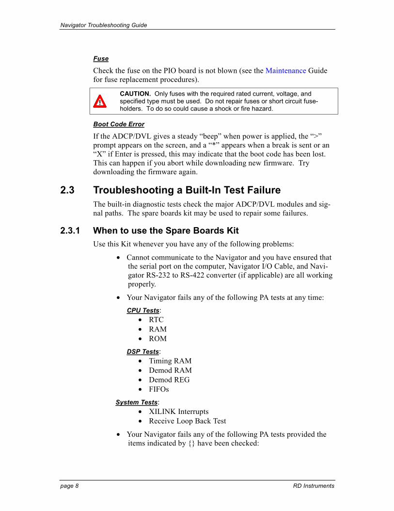
Fuse
Check the fuse on the PIO board is not blown (see the Maintenance Guide for fuse replacement procedures).
CAUTION. Only fuses with the required rated current, voltage, and specified type must be used. Do not repair fuses or short circuit fuse-holders. To do so could cause a shock or fire hazard.
Boot Code Error
If the ADCP/DVL gives a steady “beep” when power is applied, the “>” prompt appears on the screen, and a “*” appears when a break is sent or an “X” if Enter is pressed, this may indicate that the boot code has been lost. This can happen if you abort while downloading new firmware. Try downloading the firmware again.
2.3 Troubleshooting a Built-In Test Failure The built-in diagnostic tests check the major ADCP/DVL modules and sig-nal paths. The spare boards kit may be used to repair some failures.
2.3.1 When to use the Spare Boards Kit Use this Kit whenever you have any of the following problems:
• Cannot communicate to the Navigator and you have ensured that the serial port on the computer, Navigator I/O Cable, and Navi-gator RS-232 to RS-422 converter (if applicable) are all working properly.
• Your Navigator fails any of the following PA tests at any time: CPU Tests:
• RTC • RAM • ROM
DSP Tests: • Timing RAM • Demod RAM • Demod REG • FIFOs
System Tests: • XILINK Interrupts • Receive Loop Back Test
• Your Navigator fails any of the following PA tests provided the items indicated by {} have been checked:
Navigator Troubleshooting Guide
P/N 957-6178-00 (September 2001) page 9
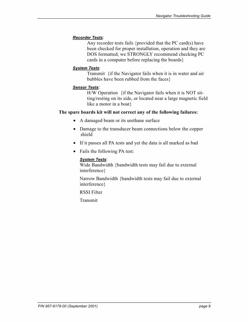
Recorder Tests: Any recorder tests fails {provided that the PC card(s) have been checked for proper installation, operation and they are DOS formatted; we STRONGLY recommend checking PC cards in a computer before replacing the boards}
System Tests: Transmit {if the Navigator fails when it is in water and air bubbles have been rubbed from the faces}
Sensor Tests: H/W Operation {if the Navigator fails when it is NOT sit-ting/resting on its side, or located near a large magnetic field like a motor in a boat}
The spare boards kit will not correct any of the following failures:
• A damaged beam or its urethane surface
• Damage to the transducer beam connections below the copper shield
• If it passes all PA tests and yet the data is all marked as bad
• Fails the following PA test: System Tests: Wide Bandwidth {bandwidth tests may fail due to external interference}
Narrow Bandwidth {bandwidth tests may fail due to external interference}
RSSI Filter
Transmit

Navigator Troubleshooting Guide
page 10 RD Instruments
Table 3: Pre-deployment Test (PA) Possible Cause of Failures PA Test Name Possible Cause of Failure Pre-Deployment Tests CPU Tests:
RTC RAM ROM
CPU board failed
Recorder Tests: PC Card #0
Card Detect Communication DOS Structure Sector Test (short)
PC Card #1 Card Detect Communication DOS Structure Sector Test (short)
PC card not plugged in PC card failed DSP board failed
DSP Tests: Timing RAM Demod RAM Demod REG FIFOs
DSP board failed
System Tests: XILINX Interrupts
DSP or CPU board failed
Receive Loop-Back DSP or CPU board failed Wide Bandwidth Narrow Bandwidth RSSI Filter
Not in water External interference DSP or Receiver board failed
Transmit Not in water or PIO board failed Sensor Tests:
H/W Operation PIO board failed Receiver board failed Pressure sensor failed ADCP/DVL laying on its’ side
2.4 Troubleshooting a Beam Failure If the beam continuity test fails, a bad DSP board, Receiver board, PIO board, or a bad beam may cause the failure. If replacing the DSP and PIO board (included with the spare boards kit) does not fix the problem, the ADCP/DVL must be returned to RDI for repair. >PC1 BEAM CONTINUITY TEST When prompted to do so, vigorously rub the selected beam's face. If a beam does not PASS the test, send any character to the ADCP/DVL to automatically select the next beam. Collecting Statistical Data... 41 46 45 43 41 46 45 43 41 46 45 42 41 46 44 42 Rub Beam 1 = PASS | NOTE – Possible cause of failure Rub Beam 2 = PASS | DSP Board Rub Beam 3 = PASS | Receiver Board Rub Beam 4 = PASS | PIO Board > | Beam

Navigator Troubleshooting Guide
P/N 957-6178-00 (September 2001) page 11
2.5 Troubleshooting a Sensor Failure If the PA test fails the sensor test, run PC2 to isolate the problem. The am-bient temperature sensor is mounted on the receiver board. This sensor is imbedded in the transducer head, and is used for water temperature reading. The attitude temperature sensor is located on the PIO board under the com-pass. The ADCP/DVL will use the attitude temperature if the ambient tem-perature sensor fails.
If one of the temperature sensors fails, the PC2 test will show both sensors at the same value. >PC2 Press any key to quit sensor display ... Heading Pitch Roll Up/Down Attitude Temp Ambient Temp Pressure 301.01° -7.42° -0.73° Up 24.35°C 22.97°C 0.0 kPa 300.87° -7.60° -0.95° Up 24.36°C 22.97°C 0.0 kPa 300.95° -7.60° -0.99° Up 24.37°C 22.97°C 0.0 kPa 300.71° -7.61° -0.96° Up 24.37°C 22.98°C 0.0 kPa 300.69° -7.61° -0.96° Up 24.35°C 22.98°C 0.0 kPa 300.76° -7.60° -0.98° Up 24.38°C 22.97°C 0.0 kPa >
NOTE. The PA test will fail if the ADCP/DVL is lying on its side or located near a large magnetic field.
NOTE. If the temperature sensor is bad, the data can still be collected with no effects to accuracy or quality. Contact RDI about scheduling a repair of the temperature sensor at your convenience.
2.5.1 Fault Log To determine why a sensor failed, view the fault log. To view the fault log, start DumbTerm. Press the End key to wakeup the ADCP/DVL. Type the following commands: CR1, FC, PA, FD. The fault log will be displayed by the FD-command. [BREAK Wakeup A] WorkHorse Broadband ADCP/DVL Version x.xx RD Instruments (c) 1996-1997 All rights reserved. >CR1 >FC >PA | (PA test results (not shown)) | >FD Total Unique Faults = 2 Overflow Count = 0 Time of first fault: 97/11/05,11:01:57.70 Time of last fault: 97/11/05,11:01:57.70 Fault Log: Entry # 0 Code=0a08h Count= 1 Delta= 0 Time=97/11/05,11:01:57.70 Parameter = 00000000h Tilt axis X over range. Entry # 1 Code=0a16h Count= 1 Delta= 0 Time=97/11/05,11:01:57.70 Parameter = 00000000h Tilt Y axis ADC under range. End of fault log.

Navigator Troubleshooting Guide
page 12 RD Instruments
2.6 Technical Support If you have technical problems with your instrument, contact our field ser-vice group in any of the following ways:
RD Instruments RD Instruments Europe 9855 Businesspark Ave. 5 Avenue Hector Pintus
San Diego, California 92131 06610 La Gaude, France
(858) 693-1178 +33(0) 492-110-930
FAX (858) 695-1459 +33(0) 492-110-931
[email protected] [email protected]
Web: http://www.rdinstruments.com
http://www.dvlnav.com
If your instrument works and you have questions involving a specific appli-cation, you may call either the field service group (above) or our sales/marketing staff.
3 Navigator Cables This section has information on Navigator cabling. Special user-requests may cause changes to the basic wiring system and may not be shown here. We provide these drawings only as a guide in troubleshooting the ADCP/DVL. If you feel there is a conflict, contact RDI for specific infor-mation about your system. The following figures show various Navigator cable locations, connectors, and pin-outs.
NOTE. Where shown, the color code is for reference only; your cable may be different.

Navigator Troubleshooting Guide
P/N 957-6178-00 (September 2001) page 13
PIN 1
PIN 9
32985
P212564
37
POWER +POWER -
COMMUNICATION RETURN
RS-232 IN / RS-422 OUT ARS-232 OUT / RS-422 OUT B
RS-422 IN ARS-422 IN B
J1
P1BLKWHTBLUBRNGRN
REDYEL
P1 J1 P2
76
5
4
12
3
Figure 1. Navigator I/O Cable Wiring
NOTE. Where shown, IN refers to signals going into the ADCP/DVL and OUT refers to signals coming out of the ADCP/DVL.
POWER +
POWER -
COMMUNICATION RETURNRS-422 IN ARS-422 IN B
RS-232 IN / RS-422 OUT ARS-232 OUT / RS-422 OUT B
BLACK
WHITE
BLUE
BROWN
GREEN
RED
YELLOW
P18PIN HEADERTO PWR I/O
J17PIN CONNEND CAP
53
78
41
6
12
56
43
7
P1
PIN 5
PIN 1
J1LPMBH-MP
76
5
4
12
3
Figure 2. Navigator Internal I/O Cable (End-Cap to PIO Board)
Wiring

Navigator Troubleshooting Guide
page 14 RD Instruments
1234567
J1
D2
P11 2 3 4 5 6 7
D1
P21234567
J1 P2
P1
Figure 3. Optional External Battery Pack “Y” Cable
P1
P2
P3
F1
P2
1
2
P3
1
2
F1
NC
NC
NC
NC
NC
P1
POWER +
POWER -
1
2
3
4
5
6
7 YEL
BRN
BLU
GRN
RED
WHT
BLK
Figure 4. Optional External Battery Case Internal Wiring

Navigator Troubleshooting Guide
P/N 957-6178-00 (September 2001) page 15
3162147
RS422 RDA
DATA COMMON
RS422 RDBRS422 TDARS422 TDB
P2ADAPTER SIDE
SOCKET
P1ADCP SIDE
PLUGREDORNYEL
GRNBLU
32985 DATA COMMON
RS422 TDARS422 TDBRS422 RDARS422 RDB
P2
25-pin to9-pin adapter(use as needed)
P1
Figure 5. Optional RS232-to-RS422 Converter Wiring (25-Pin to
9-Pin)
4 System Overview This section presents a functional description of Navigator operation using block diagrams.
4.1 Operating Modes The Navigator has two modes of operation: command mode, and ping mode (also referred to as “Deployment Saver” Mode). Depending on what mode the ADCP/DVL is in; it will go either to sleep, or to resume pinging.
4.1.1 Command Mode Whenever you wake up your Navigator, power dissipation increases from less than 1 mW to around 2.2 W. If you leave the Navigator in command mode without sending a command for more than 5 minutes, the Navigator automatically goes to sleep. This protects you from inadvertently depleting batteries.
• If the ADCP/DVL receives a BREAK, it will go to the command prompt and wait for a command. The ADCP/DVL will wait at the command prompt for five minutes. If no commands have been sent, it will go to sleep (also called “Battery Saver” mode).
• If you press the reset switch (located on the CPU board), the ADCP/DVL will go to sleep.
• If the ADCP/DVL receives a CS-command, it will go into the ping mode and begin pinging. If a TF-command (Time of First Ping) was sent prior to the CS-command, then the ADCP/DVL will go to sleep until the TF time occurs.

Navigator Troubleshooting Guide
page 16 RD Instruments
• If the ADCP/DVL does a COLD wakeup (i.e. an unknown state), it will go to the command prompt.
• If the ADCP/DVL is asleep for approximately nine hours, it wakes up to charge the capacitor used to maintain RAM. Once the capacitor is charged (this only takes a few seconds), the ADCP/DVL goes back to sleep.
4.1.2 Ping Mode After you send commands to the Navigator that tells it to start collecting data, the Navigator goes into deployment saver mode. If power is somehow removed and later restored, the Navigator simply picks up where it left off and continues to collect data using the same setup.
• If the ADCP/DVL receives a BREAK, it will go to the command prompt, but stays in the ping mode. If a valid command is re-ceived, the ADCP/DVL will switch to the command mode. If no valid command is received, a warning will be displayed after four minutes, indicating that the system will self-deploy. After a total of five minutes with no input, the ADCP/DVL will resume pinging.
• If you press the reset switch, and an alarm is currently set for the next ping, the ADCP/DVL will go to sleep. If no alarm is set, the system will start a new deployment and starts pinging immediately unless a TF-command had been set after the last BREAK. In this case, the ADCP/DVL will go to sleep until the TF time occurs.
• If the ADCP/DVL does a COLD wakeup, the system will start a new deployment and starts pinging immediately unless a TF-command had been set after the last BREAK. In this case, the ADCP/DVL will go to sleep until the TF time occurs if the TF time is valid (i.e., not in the past).
• If the ADCP/DVL is asleep for approximately nine hours, it wakes up to charge the capacitor used to maintain RAM. Once the capacitor is charged, if a valid alarm is set for the next ping time, the ADCP/DVL goes back to sleep and waits for the alarm. If no alarm is set, the ADCP/DVL will resume pinging immedi-ately, or wait for the TF time (if valid), and then start pinging.

Navigator Troubleshooting Guide
P/N 957-6178-00 (September 2001) page 17
4.2 Overview of Normal Navigator Operation Refer to Figure 6, page 20 through Figure 9, page 23. The following events occur during a typical data collection cycle.
a. The user or a controlling software program sends data collection pa-rameters to the Navigator. The user/program then sends a CS-command to start the data collection cycle. The firmware program stored in the CPU microprocessor takes control of Navigator operation based on the commands received through the serial I/O cable.
Figure 6, page 20 shows a flow chart of the wake-up logic used by the Navigator. The Navigator determines what to do based on where the wake-up came from (a Break, CS-command, battery saver timer, or watchdog timer was detected).
b. On the PIO Board, the POWER REGULATOR circuit sends a transmit command to the POWER AMPLIFIER circuit. This tells the Navigator to start acoustic transmissions (pinging) on all TRANSDUCERS.
c. The TRANSDUCERS receive echoes from the backscatter. The RECEIVER board amplifies and translates the echoes into a base-band frequency.
d. The CPU board processes the received echoes.
e. After echo reception, the Navigator injects a self-test signal into the RECEIVER board and processes the signal as normal data for test pur-poses.
f. The THERMISTOR measures water temperature at the transducer head and sends it to the CPU via the DSP Board.
g. The PIO Board sends pitch and roll from the TILT SENSOR and Navi-gator heading from the COMPASS to the DSP Board. The DSP Board digitizes this information and sends it to the CPU for processing.
h. The CPU repeats steps “b” through “g” for a user-defined number of pings. The CPU averages the data from each ping to produce an ensem-ble data set.
i. At the end of the ensemble (sampling) interval, the CPU sends the col-lected data to the serial I/O connector or PCMCIA recorder.

Navigator Troubleshooting Guide
page 18 RD Instruments
4.3 Functional Description of Operation The following paragraphs describe how the Navigator operates and interacts with its modules. Refer to Figure 6, page 20 through Figure 9, page 23 throughout this description.
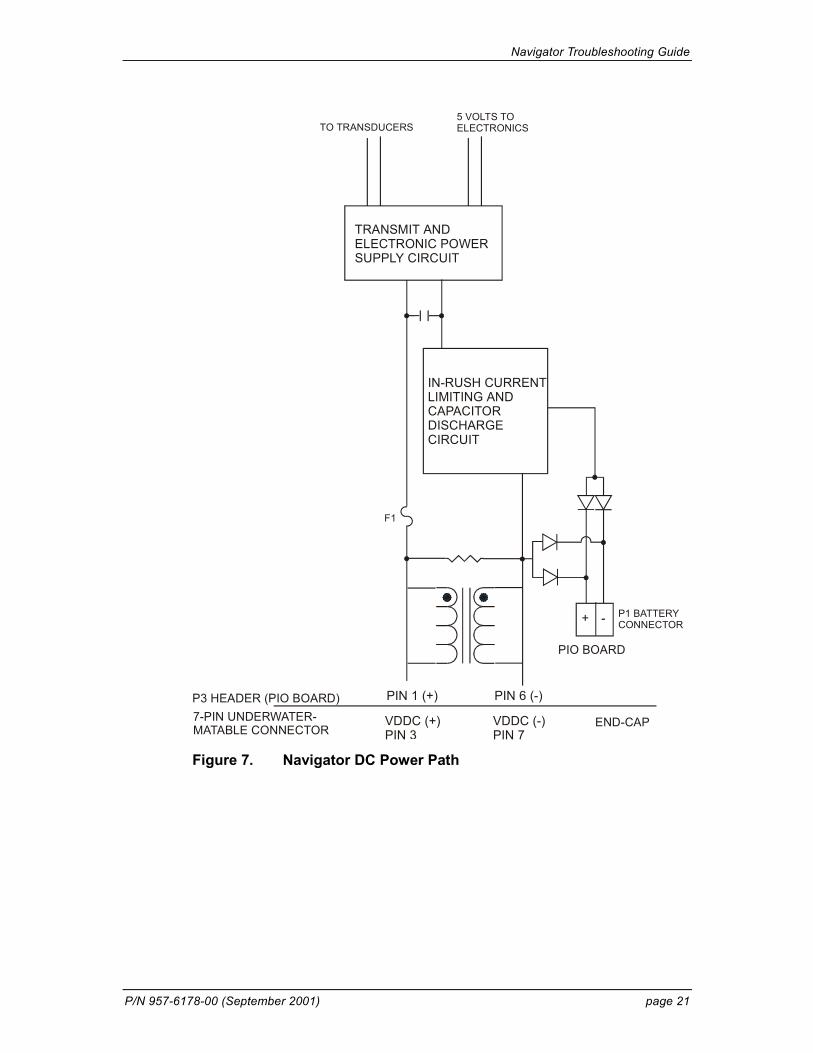
4.3.1 Input Power The Navigator requires a DC supply between 20 volts and 60 volts. Either an external DC power supply or optional external battery pack can provide this power. Figure 7, page 21 shows the DC voltage power distribution path.
Power is applied to pins 3 (positive) and 7 (negative) on the external con-nector (see Figure 8, page 22). The power then goes through an electro-magnetic interference (EMI) filter on the PIO Board. This filter reduces the chance that external noise sources associated with the external power source can disrupt Navigator operation.
4.3.2 Board Descriptions PIO Board.
• Receives the filtered/internal power.
• Uses a diode “OR” gate to determine which power source to use (external or internal). With both sources connected, the OR gate selects the “higher” voltage for Navigator use.
• Limits the in-rush of current to the Navigator and provides over- and negative-voltage protection. Either condition will blow a protective fuse. However, damage could occur to other circuits before the fuse blows. Please ensure you apply only voltages within the specified range (+20 to +60 VDC).
• Converts the operating power supply (filtered/isolated 20 to 60 VDC) in a DC-to-DC converter to the +5 VDC (Vcc) used to power all other Navigator circuits.
• Uses the Power Amplifier circuit on the PIO board to generate the high-amplitude pulse AC signal that drives the sonar trans-ducers. The Power Amplifier sends the drive signal to the Re-ceiver Board.
• RS-232/RS-422 switch.
Navigator Troubleshooting Guide
P/N 957-6178-00 (September 2001) page 19
CPU Board.
• Real time clock.
• Generates most of the timing and logic signals used by the Navi-gator.
DSP Board.
• Contains the PCMCIA recorder slots.
• Analog to Digital converter.
• Digitizes information from sensors and sends sensor information to the CPU.
Receiver Board.
• Tuning functions
• Receiver functions
• Temperature sensor
• Interface for pressure sensor
4.3.3 Sensors This section describes the standard Navigator sensors. The PIO and DSP boards control the environmental sensors and contain unit-specific data. Sensors include:
Temperature Sensor (thermistor) - Used to measure the water temperature. The system uses this data to calculate the speed of sound. This sensor is embedded in the transducer head and is not field replaceable.
Up/Down Sensor - Determines whether the transducer head is facing up or down. This sensor is located on the PIO board.
Compass - Determines the Beam 3 heading angle of the Navigator using a flux-gate compass. This sensor is located on the PIO board. The flux-gate measured earth magnetic field vector together with the tilt sensor pitch and roll information is used to determine the heading. Since the tilt sensor data is only valid when the ADCP/DVL is ±20° from vertical, the heading in-formation is also limited to this range.
Attitude Sensor - Determines the tilt angles of the Navigator. This sensor is located on the PIO board. The attitude sensor uses a pitch and roll liquid-filled sensor. This sensor is functional to an angle of ±20° from vertical. Pressure Sensor (optional) - Measures pressure at the Navigator transducer. This sensor is embedded in the transducer head and is not field replaceable.

Navigator Troubleshooting Guide
page 20 RD Instruments
The CPU microprocessor controls a multiplexed analog-to-digital converter to accept analog data from the sensors. Digital data are taken in directly. The pressure sensor incorporates a Wheatstone Bridge strain gage to meas-ure the water pressure at the transducer faces. Depth is calculated from pressure, with water density adjusted by the salinity (ES) setting.
Calibration data for the sensors, a beam-angle correction matrix, and unit identification parameters (frequency, serial number, firmware version, etc.) are stored in ROM.
P IN G
< B R E A K >Sent?
ResetPressed?
No
T URNKEY ORPingingA CTIVE?
N O
A LARM SET BYADCP onprev ping?
Yes
RESET ALARM
A LARMwakeup?
BatterySaver
W ATCHDOGtimeout?
C HARACTERreceived?
Reset batterysaver
watchdog
P ROMPT
Wakeup
RestoreFACTORY
DefaultsYes
Restore USERD EFAULTS
Good RAMChecksum?
G OODEEPROM
checksum?Yes No
Y ES
RestoreFACTORYDefaults
No
Yes
Yes
N O
Restore USERDefaults
[RESET]
[CLOCK]
[COLD]
SLEEP
R ESET PingingA CTIVE Flag
<CR>received?
No No
"CS"Received?
Yes
ProcessCommand
Set PingingActive Flag
(S ETUPPinging)
RestorePinging
Conditions
No
Y ES
Yes
Restart?
[RESTART]
No
Yes
NO
Yes
No
No
Watchdog /Restart
Timeout?
Yes
No
Wake-up Logic
B ATTERY S AVER T IMER L OGICWatch-dog Timer Logic Figure 6. Navigator Wake-up and Timer Logic
Navigator Troubleshooting Guide
P/N 957-6178-00 (September 2001) page 21
P3 HEADER (PIO BOARD)
F1
END-CAP7-PIN UNDERWATER-MATABLE CONNECTOR
PIO BOARD
P1 BATTERYCONNECTOR+ -
TO TRANSDUCERS5 VOLTS TOELECTRONICS
VDDC (+)PIN 3
VDDC (-)PIN 7
PIN 1 (+) PIN 6 (-)
IN-RUSH CURRENTLIMITING ANDCAPACITORDISCHARGECIRCUIT
TRANSMIT ANDELECTRONIC POWERSUPPLY CIRCUIT
Figure 7. Navigator DC Power Path

Navigator Troubleshooting Guide
page 22 RD Instruments
EXTERNALCONNECTOR
UART (4)
SERIALDRIVER (2) &RECEIVERS
RTC CIRCUIT
TEMPSENSOR
COMPASS &ATTITUDESENSORS
COMMONMODE CHOKE
PIO BOARD
DSP BOARD
RECEIVER BOARD
20 to 60 VDC EXTERNAL
POWERCOMMUNICATIONS
EMI CIRCUIT
POWER CONDITIONING CIRCUIT
TRANSMIT POWERAMPLIFIER CIRCUIT
BEAM 1 BEAM 2 BEAM 3 BEAM 4
TUNING CIRCUIT
PCMCIA RECORDER
CPU BOARD
Figure 8. Navigator Block Diagram

Navigator Troubleshooting Guide
P/N 957-6178-00 (September 2001) page 23
I/O CABLE CONNECTOR ANDCOMMON MODE CHOKE
SPACER
GROUNDJUMPER
COMPASS
TRANSMITCABLE P3
FUSE
BATTERYCONNECTOR
COMPASS
RS-232/RS-422SWITCH
PIO BOARD
CPU BOARD
DSP BOARD PC CARD RECORDERSHIELD
Figure 9. Navigator PC Board Locations

Navigator Troubleshooting Guide
page 24 RD Instruments
NOTES