navy maint. & op of active solar heating sy
TRANSCRIPT

8/14/2019 Navy Maint. & Op of Active Solar Heating Sy
http://slidepdf.com/reader/full/navy-maint-op-of-active-solar-heating-sy 1/277
S/N 0525-LP-193-4800 NAVFAC MO-405
JULY 1990

8/14/2019 Navy Maint. & Op of Active Solar Heating Sy
http://slidepdf.com/reader/full/navy-maint-op-of-active-solar-heating-sy 2/277
SNDL DISTRIBUTION
(25 copies each):
FKA1C COMNAVFACENGCOM
(10 Copies each):
FA46 PWCLANTFB54 PWCPAC
HQ U.S. AIR FORCEEngineering And Services CenterTyndall AFB, FL 32403
(2 Copies each):
E3A LABONR FA6 NASLANTFA7 NAVSTALANT
FA10 SUBASELANTFA18 NAVPHIBASELANTFA24 COMNAVBASELANTFB7 NASPACFB10 NAVSTAPACFB13 SUBBASEPACFB21 NAVPHIBASEPACFB28 COMNAVBASEPACFB30 NAVSHIPREPFACFB36 NAVFACPACFB45 TRIREFFACPACFC3 COMNAVACTEUR FC5 NAVSUPACTEUR
FC7 NAVSTAEUR FC14 NASEUR FD4 OCEANCENFFl COMNAVDICT Washington,DCFF3 NAVSTACNOFF6 NAVOBSYFF32 FLDSUPPACTFF38 USNA FF42 NAVPGSCOLFG2 NAVCOMMSTA FH3 NAVHOSPFJA4 NAVAL HOMEFKA8F5 SUBASE
FKM9 NSC
FKN1 EFDs
FKP7 NAVSHIPYDsFT104 PWCCNET
U.S. ARMYOffice of Engineers
Washington, DC 20314 (DAEN-MPO)
FKM12 NAVPETOFFFKM13 SPCCFKN2 CBCs
FKN3 OICCSFKN7 NEESA FKN10 NAVSUPPFACFKN11 NAVCIVENGRLABFKP1B WPNSTAsFKP1J NAVORDSTAsFKP16 NAVSSESFKR1A NASFKR1B NAVAVNDEPOTFKR3A NAVAIRENGCENFR3 NASRESFOR FR4 NAFFT6 NASCNET
FT9 NAVAVMUSEUM FT13 NATTCFT28 NETCFT31 NTCFT37 NAVSCOLCECOFFFT38 NAVSUBTRACENPACFT39 NAVTECHTRACENFT55 NAVSCSCOL
V3 COMCAB V4 MCAF V5 MCAS V8 CG MCRD V16 CG MCB
V23 CG MCLB
Additional Copies may be obtained from: Navy Publications and Forms Center5801 Tabor AvenuePhiladelphia, PA 19120

8/14/2019 Navy Maint. & Op of Active Solar Heating Sy
http://slidepdf.com/reader/full/navy-maint-op-of-active-solar-heating-sy 3/277
FOREWORD
This Maintenance and Operations (MO) Manual contains information on theoperation, inspection, troubleshooting, repair and maintenance of liquid solarheating systems. That is, solar heating or cooling systems using liquid, rather thanair, to gather heat, pumps to move it and tanks of water to store it.
The standards and methods presented are intended to accomplish the inspection,maintenance, and repair of liquid solar heating and cooling systems in the mostefficient and cost effective manner.
Recommendations or suggestions for modification, or additional information andinstructions that will improve the publication and motivate its use, are invited andshould be forwarded to the Commander, Naval Facilities Engineering Command(Attention: Code 163), 200 Stovall Street, Alexandria, VA, 22332-2300. Telephone:Commercial (202)-325-0045, Autovon 221-0045.
This publication has been reviewed and is approved for certification as an officialpublication of this command in
Deputy Commander forPublic Works
i
8/14/2019 Navy Maint. & Op of Active Solar Heating Sy
http://slidepdf.com/reader/full/navy-maint-op-of-active-solar-heating-sy 4/277
NOTICE
The preparation of this manual was sponsored by the United States Government.Neither the United States, nor the United States Department of Defense, nor any oftheir employees, nor any of their contractors, subcontractors or their employees,makes any warranty, expressed or implied, or assumes any legal liability orresponsibility, for the accuracy, completeness or usefulness of any information,apparatus, product or process disclosed, or represents that its use would notinfringe privately owned rights.
The practices and procedures presented in this manual are recommendations onlyand do not supersede any applicable local, state or national building, electrical,plumbing or other code requirements. The reader is responsible for determining theapplicable code requirements and remaining in compliance with them.
i i

8/14/2019 Navy Maint. & Op of Active Solar Heating Sy
http://slidepdf.com/reader/full/navy-maint-op-of-active-solar-heating-sy 5/277
ABSTRACT
This manual is a guide for engineers, planners, maintenance supervisors and allmaintenance personnel involved in the operation, inspection, troubleshooting, repairand maintenance of liquid solar heating systems. That is, solar heating or coolingsystems using liquid, rather than air, to gather heat, pumps to move it and tanks ofwater to store it. The manual is designed to be used in the field by the personnelperforming the actual inspection, maintenance or repair of solar systems.
i i i

8/14/2019 Navy Maint. & Op of Active Solar Heating Sy
http://slidepdf.com/reader/full/navy-maint-op-of-active-solar-heating-sy 6/277

8/14/2019 Navy Maint. & Op of Active Solar Heating Sy
http://slidepdf.com/reader/full/navy-maint-op-of-active-solar-heating-sy 7/277
CHANGE CONTROL SHEET
Document all changes, page replacements, and pen and ink alterations posted in this manual.
AMENDMENT AMENDMENT POST DATE POSTED BYNUMBER DATE (LAST NAME)
v

8/14/2019 Navy Maint. & Op of Active Solar Heating Sy
http://slidepdf.com/reader/full/navy-maint-op-of-active-solar-heating-sy 8/277

8/14/2019 Navy Maint. & Op of Active Solar Heating Sy
http://slidepdf.com/reader/full/navy-maint-op-of-active-solar-heating-sy 9/277
TABLE OF CONTENTS
1. Introduction. . . . . . . . . . . . . . . .1.1 Purpose of this Manual. . . . . . . . . . .1.2 Scope of this Manual. . . . . . . . . . .
1.3 How to Use this Manual. . . . . . . . . .1.3.1 Review of Manual Structure. . . . . .1.3.2 Worksheets. . . . . . . . . . .
1.3.3 Self-study Questions. . . . . . . .
1.3.4 Appendices.. . . . . . . . . .
1.3.5 Notes, Cautions and Warnings. . . . .1.3.6 Chapter and Page Format. . . . . . .
2. Operation. . . . . . . . . . . . . . . .
2.1 Basic System Configuration. . . . . . . . .
2.1.1 Definition of Loops . . . . . . . .
2.1.2 Common Components. . . . . . . .2.1.3 Common Load Connections. . . . . .
2.2 Basic Configuration of Closed-Loop Systems. . . .
2.3 Basic Configuration of Drainback Systems . . . .2.4 Basic Configuration of Draindown Systems. . . .
2.5 Basic Configuration of Thermosiphon Systems . . . .2.6 Basic Configuration of Integrated Collector-Storage
System. . . . . . . . . . . . . . .
2.7 Component Operation . . . . . . . . . . .2.7.1 Solar Collectors . . . . . . . . .2.7.2 Pumps. . . . . . . . . . . .
2.7.3 Piping.2.7.4 Solar Fluids.
. . . . . . . . . .
. . . . . . . . . .
2.7.5 Heat Exchangers. . . . . . . . .
2.7.6 Storage Tanks. . . . . . . . . .
2.7.7 Valves and Other Components. . . . .
2.7.8 Pipe and Tank Insulation. . . . . . .2.7.9 Controls and Sensors. . . . . . .
1
1
23333334
55568
141617
18
192020232526283033
4750
vi i

8/14/2019 Navy Maint. & Op of Active Solar Heating Sy
http://slidepdf.com/reader/full/navy-maint-op-of-active-solar-heating-sy 10/277
2.7.10 Gauges. . . . . . . . . . . . 552.8 Questions for self-study. . . . . . . . . . 58
3. Inspection. . . . . . . . . . . . . . . . . . 613.1 Inspection Procedures. . . . . . . . . . . 62
3.1.1 Solar Collectors. . . . . . . . . . 623.1.2 Exterior Piping. . . . . . . . . . 703.1.3 Interior Piping. . . . . . . . . . 723.1.4 Pumps. . . . . . . . . . . . . 753.1.5 Heat Exchangers. . . . . . . . . 813.1.6 Solar Fluids. . . . . . . . . . . 823.1.7 Controls . . . . . . . . . . . 853.1.8 Storage Tanks. . . . . . . . . . 93
3.2 Sample Inspection Checklist. . . . . . . . 943.3 Simplified Inspection Procedures for Small Systems3.4 Questions for Self-study . . . . . . . . .
. 99102
4. Troubleshooting . . . . . . . .4.1 Troubleshooting Techniques . . .4.2 Troubleshooting Chart. . . .4.3 Specific Troubleshooting Operations.
4.3.1 Sensor and Sensor Wiring4.3.2 Controls . . . . . .4.3.3 Airbound Loops . . . .4.3.4 Pumps.4.3.5 Flow Rates . . . . .4.3.6 Fluids . . . . . . .4.3.7 Piping Joints . . . .
4.3.8 Valves . . . . . .4.3.9 Heat Exchangers. . . .4.3.10 Insulation. . . . . .4.3.11 Gauges .4.3.12 Storage Tanks . . . .
4.4 Questions for Self-study . . . .
. . . . . 105
. . . . . 105
. . . . . 108
. . . . . 111
. . . . . 111
. . . . . 115
. . . . . 120
. . . . . 123
. . . . . 125
. . . . . 126
. . . . . 129
. . . . . 130
. . . . . 131
. . . . . 131
. . . . . 132
. . . . . 132
. . . . . 133
5. Repair.5.1 Repair or Replace? . . . . . . . . . .
. . . . . . . . . . . . . . . . . . 137137
5.2 Repair and Replacement Procedures . . . . . 1415.2.1 Solar Collectors . . . . . . . . . 141
5.2.2 Interior and Exterior Piping . . . . . 1545.2.3 Dry Rotor Pumps . . . . . . . . 1625.2.4 Wet Rotor Pumps . . . . . . . . 1685.2.5 Heat Exchangers. . . . . . . . . 1715.2.6 Solar Fluids . . . . . . . . . . 175
viii

8/14/2019 Navy Maint. & Op of Active Solar Heating Sy
http://slidepdf.com/reader/full/navy-maint-op-of-active-solar-heating-sy 11/277
5.2.7 Solar Controls . . . . . . . . . 1875.2.8 Storage Tanks . . . . . . . . . 190
5.3 Sample Repair Record Sheet. . . . . . . . 1955.4 Questions for Self-study . . . . . . . . . 197
6. Preventive Maintenance . . . . . . . . . .6.1 Maintenance Procedures
201. . . . . . . . . 2016.1.1 Solar Collectors . . . . . . . . . 2016.1.2 Interior and Exterior Piping . . . . . 2096.1.3 Pumps . . . . . . . . . . . 2126.1.4 Heat Exchangers. . . . . . . . . 2146.1.5 Solar Fluids . . . . . . . . . . 2166.1.6 Controls . . . . . .6.1.7 Storage Tanks . . . .
217. . . . . 220
6.2 Sample Maintenance Checklist . . . . . . . 2226.3 Questions for Self-study . . . . . . . . . 226
Bibliography . . . . . . . . . . . . . . Bibliography-1
Appendix A. Standardized System Designs. . . . . . . A-1Appendix B: Rules of Thumb for Solar Systems . . . . . B-1Appendix C: Tool, Material and Spare Parts Lists . . . . C-1Appendix D: Product and Supplier Information . . . . . D-1Appendix E: Fluids and Materials Compatibility. . . . . . E-1Appendix F: Answers to Self-study Questions . . . . . . F-1
Index . . . . . . . . . . . . . . . . Index-1
ix

8/14/2019 Navy Maint. & Op of Active Solar Heating Sy
http://slidepdf.com/reader/full/navy-maint-op-of-active-solar-heating-sy 12/277
LIST OF FIGURES
Figure 2-1: A Piping Loop . . . . . . . . . . .Figure 2-2: A Recirculating DHW System . . . . . .Figure 2-3: A Simplified Solar System .Figure 2-4: A Properly Piped Flat-Plate Collector Array . . .Figure 2-5: Solar Storage Tank in Series With DHW Auxiliary
H e a t e r . . . . . . . . . . . . .Figure 2-6: A Forced Air Heating System . . . . . . .Figure 2-7: A Hydronic Heating System . . . . . . .Figure 2-8: An Absorption Cooling System . . . . . .Figure 2-9: A Pool Heating System. . . . . . . . .Figure 2-10: Fluid in a Loop . . . . . . . . . . .Figure 2-11: A Closed-Loop Solar Heating System. . . . .Figure 2-12: A Drainback Solar Heating System . . . . .Figure 2-13: A Draindown Solar Heating System . . . . .
Figure 2-14: A Thermosiphon System . . . . . . . .Figure 2-15: An ICS System . . . . . . . . . . .Figure 2-16: Direct, Diffuse and Reflected Solar Radiation . .Figure 2-17: A Typical Flat-plate Solar Collector . . . . .Figure 2-18: Single and Double Wall Evacuated Tube CollectorsFigure 2-19: An Unglazed Pool Heating Solar Collector . . .Figure 2-20: Wet Rotor Circulating Pumps . . . . . . .Figure 2-21: Dry Rotor Circulating Pumps . . . . . . .Figure 2-22:A Tube-in-Tube Heat Exchanger . . . . . .Figure 2-23: A Coil-in-Tank Heat Exchanger . . . . . .Figure 2-24:A Shell and Tube Heat Exchanger . . . . .Figure 2-25: Glass Lined Storage Tank . . . . . . .Figure 2-26: Stone Lined Storage Tank . . . . . . .Figure 2-27: A Gate Valve and a Ball Valve . . . . . . .Figure 2-28: Balancing Valves and Thermometers Installed
on a Collector Array. . . . . . . . . .Figure 2-29:Swing and Spring Check Valves . . . . .Figure 2-30: Pressure Relief Valves . . . . . . . .Figure 2-31: A Temperature and Pressure Relief Valve . . .
Figure 2-32: The Fill/Drain Assembly During System Filling . . .Figure 2-33: Proper Expansion Tank Placement . . . . .Figure 2-34:An Expansion Tank Without a Diaphragm as Fluid
Pressure Increases . . . . . . . . . .
Figure 2-35: An Expansion Tank With a Diaphragm as FluidPressure Increases . . . . . . . . . .
Figure 2-36: Proper Backflow Preventer and Expansion Tank . .P l a c e m e n t . . . . . . . . . . . . . . .
Figure 2-37: Baseboard Tee with Coin Vent (top) and a Boiler . .
Drain (Bottom. . . . . . . . . . . . . .
5678
91011
121314151617
18
20
19
212223242529293031
3234
353536363738
39
39
41
42
x

8/14/2019 Navy Maint. & Op of Active Solar Heating Sy
http://slidepdf.com/reader/full/navy-maint-op-of-active-solar-heating-sy 13/277
Figure 2-38: An Automatic Air Vent . . . . . . . . .Figure 2-39: A Manual Air Vent . . . . . . . . . .Figure 2-40: An Air Eliminator. . . . . . . . . . .Figure 2-41: A Draindown System Using Three Solenoid Valves .Figure 2-42: An Automatic Draindown Control Valve . . . .
Figure 2-43: A Vacuum Breaker . . . . . . . . . .Figure 2-44: A Manual Three-Way Valve . . . . . . .Figure 2-45: Closed Cell, Fiberglass and Elastomer Insulation .Figure 2-46: Storage Tank Insulation. . . . . . . . .Figure 2-47: Various Thermistor Sensors . . . . . . .Figure 2-48: A Pool System Collector Sensor . . . . . .Figure 2-49: A Typical Differential Thermostat Showing High Limit
Adjustment Dial (left) and Switch (right) . . . .Figure 2-50: Freeze Snap Switch Sensor . . . . . .Figure 2-51: Insertion Thermometers with PT Plugs . . . .Figure 2-52: Thermometer with Instrument Well . . . . .
Figure 2-53: A Single Pressure Gauge for Measuring Pressureon Either Side of a Pump . . . . . . . .Figure 2-54: A BTU Meter System . . . . . . . . .
4243444545
4647495051
52
53545556
5757
Figure 3-1 : Condensation on a Collector Glazing 63Figure 3-2: Outgassed Material on a Collector Glazing . . . . 64Figure 3-3: Collector Weep Hole Locations . . . . . . 65Figure 3-4: A Properly Grounded Collector . . . . . . 67Figure 3-5: An Automatic Air Vent . . . . . . . . 68Figure 3-6: A Manual Air Vent . . . . . . . . . . 69Figure 3-7: Poor Sensor Placement and Improper Insulation
Coverage. . . . . . . . . . . . . 70Figure 3-8: Shrunken Insulation Exposing Pipe . . . . . 72Figure 3-9: Schrader Valve on a Diaphragm-Type
Expansion TankFigure 3-10: Pump With a Pressure Gauge on Each Side. . .
7576
Figure 3-11: Calibrated Gauges With the Pump Off and On . . 77Figure 3-12: Gauges Out of Calibration With the Pump Off and On 78Figure 3-13: A Single Pressure Gauge Capable of Measuring Both
Pump Inlet and Outlet Pressure. . . . . . . 78Figure 3-14: A Typical Pump Curve . . . . . . . . . 79Figure 3-15: Dowfrost Test Kit . . . . . . . . . . 84Figure 3-16: Optical Refractometer . . . . . . . . . 84Figure 3-17: Checking On/Off Operation by the Jumper Method 85Figure 3-18: High Limit Dial and Control Switch
on a Solar Control . . . . . . . . . .Figure 3-19: Checking High Limit Function With a Single Resistor
8687
Figure 3-20: Solar Control Tester. . . . . . . . . . 88
xi

8/14/2019 Navy Maint. & Op of Active Solar Heating Sy
http://slidepdf.com/reader/full/navy-maint-op-of-active-solar-heating-sy 14/277

8/14/2019 Navy Maint. & Op of Active Solar Heating Sy
http://slidepdf.com/reader/full/navy-maint-op-of-active-solar-heating-sy 15/277
Figure 5-29: Special Fill/Drain Assembly Fittings . . . . . 182Figure 5-30: Air Coming From the Drain HoseFigure 5-31: Correct and Incorrect Pouring from a 5 Gallon
. . . . . 182
Drum without a Spout . . . . . . . . . 183
Figure 5-32: Routing Sensor Wires . . . . . . . . . 188Figure 5-33: Installing a Sensor on a Tank Wall StudFigure 5-34: Clamping the High Limit Sensor to Tank Outlet . . .
. . . 194194
Figure 6-1: Condensation and Outgassing . . . . . . 202Figure 6-2: Resealing a Collector with Silicone Sealant . . . . . 204Figure 6-3: Collector Weep Hole Locations . . . . . . 205Figure 6-4: Misaligned Collectors . . . . . . . . . 206Figure 6-5: A Properly Grounded Collector . . . . . . 207Figure 6-6: Schrader Valve on a Diaphragm-type
Expansion Tank.. . . . . . . . . . . 211
Figure 6-7: Sleeve Bearings Lubricated by Oil (left) and BallBearings Lubricated by Grease (right) . . . . 213Figure 6-8: Checking On/Off Operation by the Jumper Method. 217Figure 6-9: Checking High Limit Function with a Single Resistor 218Figure 6-10: Solar Control Tester. . . . . . . . . . 219
Figure A-1Figure A-2Figure A-3:Figure A-4:Figure A-5:Figure B-1 :
Figure B-2:Figure B-3:Figure B-4:
Closed-loop System . . . . . . . . . A-2Drainback System . . . . . . . . . . A-2Draindown System . . . . . . . . . A-3Direct Pool System . . . . . . . . . A-3Absorption Cooling SystemCollector Tilt Measured from the Horizontal
A-4
on Level and Tilted Surfaces . . . . . . . B-4lsogonic Map of the United States . . . . . B-5Magnetic Variation on a Compass . . . . . B-5Collector Orientation . . . . . . . . . B-6
xiii

8/14/2019 Navy Maint. & Op of Active Solar Heating Sy
http://slidepdf.com/reader/full/navy-maint-op-of-active-solar-heating-sy 16/277
LIST OF TABLES
Table 2-1: Pump Application Guide . . . . . . . . . 24Table 2-2: Typical Solar Pipe Insulations . . . . . . . 48Table 2-3: Control Features and System Types. . . . . . 54
Table 3-1: Current Readings and Pump Problems.. . . . . 80Table 3-2: Characteristics of Available Controls . . . . . 87Table 3-3: Temperature vs. Resistance in Ohms for 10K Sensors 91
Table 3-4: Temperature vs. Resistance in Ohms for 3K Sensors 92
Table 4-1: Temperature vs. Resistance in Ohms for 10K Sensors 113Table 4-2: Temperature vs. Resistance in Ohms for 3K Sensors 114Table 4-3: Resistance and Color Codes for Typical High Limit
SituationsTable 4-4: Characteristics of Currently Available Controls .
. . . . . . . . . . . . . . 117. . 119
Table 4-5: Current Readings and Pump Problems . . . . 124Table 4-6: Flow Estimates from Temperature Changes . . . 126
Table 5-1: Typical Repair/Replace Choices . . . . . .Table 5-2: Repairability of Various Absorbers Manufactured
138
for Use by Others . . . . . . . . 149Table 5-3: Repairability of Various Absorbers Manufactured
by Collector Manufacturers . . . . . 150Table 5-4: Component Fluid Capacities . . . . . . . 185Table 5-5: Fluid Pressure for Closed Loops . . . . . . 187
Table B-1: Suggested Flow Rates for Solar Applications ..
. B-2Table B-2: Flow Rates for Various Copper Tubing Sizes . . B-3Table B-3: Solar Collector Tilt Angles . . . . . . . . B-4Table C-1: Recommended Tool List . . . . . . C-2Table C-2: Recommended Material List . . . . . . . . C-3Table C-3: Recommended Spare Parts List. . . . . . . C-5
xiv

8/14/2019 Navy Maint. & Op of Active Solar Heating Sy
http://slidepdf.com/reader/full/navy-maint-op-of-active-solar-heating-sy 17/277
1 . 0INTRODUCTION
What You Will Find in This Chapter
This chapter presents the purpose, scope and structure of the manual. Also,recommended ways to use the manual are described.
Please read this chapter carefully; it will enable you to effectively use this manual insolar heating system operation, inspection, troubleshooting, repair and maintenance
activities.
1.1 PURPOSE OF THIS MANUAL
This manual provides information on the operation, inspection, troubleshooting,repair and maintenance of liquid solar heating systems. That is, solar heating orcooling systems using liquid, rather than air, in the solar collectors to gather heat,pumps to move it and tanks of water to store it. Solar electric (photovoltaic) systemswhich generate electricity directly from solar energy are addressed in their ownmanual.
We assume the reader is confronted with an existing system, and wants an answerto one of the following questions:
o How does it work? (Operation)o Is it working? (Inspection)o What’s wrong with it? (Troubleshooting)o How do I fix it? (Repair)o How do I keep it working? (Maintenance)
NOTE
This manual is designed to be used in the field by staffperforming the actual inspection, maintenance or repair ofsolar systems. Do not let it collect dust on a shelf!
1
INTRODUCTION
1.1 PURPOSE OF THIS MANUAL

8/14/2019 Navy Maint. & Op of Active Solar Heating Sy
http://slidepdf.com/reader/full/navy-maint-op-of-active-solar-heating-sy 18/277
The physical structure of the manual has been designed for easy copying. Manypages are sample worksheets and forms that must be copied to be used with therecommended procedures.
1.2 SCOPE OF THIS MANUAL
The manual covers service issues for systems using flat-plate, evacuated tube, orunglazed (pool) solar collectors.
It examines four loads that can be met by solar heating. These are domestic andprocess hot water, space heating, space cooling and swimming pool heating. Thesefour applications represent the vast majority of Navy solar systems. They also offerthe reader a fairly broad look at the types of interconnections between solar systemsand loads.
Chapters of this manual are:
Chapter 2 - OperationChapter 3 - InspectionChapter 4 - TroubleshootingChapter 5 - RepairChapter 6 - Preventative Maintenance
System design is not specifically addressed. However, it cannot be completelyignored. If the system design is inadequate or incorrect, it will affect systemoperation and maintenance.
For this reason, Appendices A and B include “generic” system designs and sizingguidelines. These are based on ongoing efforts by military and civilian authorities tostandardize the layout and sizing of components in solar systems. Hopefully, thiswill simplify the operation and maintenance of solar systems installed orrehabilitated in the future.
The information in Appendices A and B assists the service staff to determine whenperformance problems are actually caused by design errors. These Appendicesshow correct system designs, but they are not meant to replace a design guide.
INTRODUCTlON
1.2 SCOPE OF THIS MANUAL 2
8/14/2019 Navy Maint. & Op of Active Solar Heating Sy
http://slidepdf.com/reader/full/navy-maint-op-of-active-solar-heating-sy 19/277
1.3 HOW TO USE THIS MANUAL
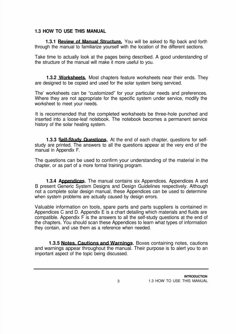
1.3.1 Review of Manual Structure, You will be asked to flip back and forththrough the manual to familiarize yourself with the location of the different sections.
Take time to actually look at the pages being described. A good understanding ofthe structure of the manual will make it more useful to you.
1.3.2 Worksheets, Most chapters feature worksheets near their ends. Theyare designed to be copied and used for the solar system being serviced.
The’ worksheets can be “customized” for your particular needs and preferences.Where they are not appropriate for the specific system under service, modify theworksheet to meet your needs.
It is recommended that the completed worksheets be three-hole punched andinserted into a loose-leaf notebook. The notebook becomes a permanent servicehistory of the solar heating system.
1.3.3 Self-Study Questions, At the end of each chapter, questions for self-study are printed. The answers to all the questions appear at the very end of themanual in Appendix F.
The questions can be used to confirm your understanding of the material in thechapter, or as part of a more formal training program.
1.3.4 Appendices. The manual contains six Appendices. Appendices A andB present Generic System Designs and Design Guidelines respectively. Althoughnot a complete solar design manual, these Appendices can be used to determinewhen system problems are actually caused by design errors.
Valuable information on tools, spare parts and parts suppliers is contained inAppendices C and D. Appendix E is a chart detailing which materials and fluids arecompatible. Appendix F is the answers to all the self-study questions at the end ofthe chapters. You should scan these Appendices to learn what types of informationthey contain, and use them as a reference when needed.
1.3.5 Notes. Cautions and Warnings. Boxes containing notes, cautionsand warnings appear throughout the manual. Their purpose is to alert you to animportant aspect of the topic being discussed.
INTRODUCTION
3 1.3 HOW TO USE THIS MANUAL

8/14/2019 Navy Maint. & Op of Active Solar Heating Sy
http://slidepdf.com/reader/full/navy-maint-op-of-active-solar-heating-sy 20/277
NOTES provide helpful information that does not otherwise fit into the text.
CAUTIONS draw attention to the possibility of equipment damage if the instructionsare not followed.
WARNINGS draw attention to the possibility of personal injury if the instructions arenot followed.
1.3.6 Chapter and Page Format A three-point system is used on every pageto let you know where you are in the manual. First, a footer at the bottom “outside”of every page shows the chapter title. On this page it is “INTRODUCTION.”
The second point is a footer below the chapter title with the section number and title.For example, “1.3 HOW TO USE THIS MANUAL” on this page.
Finally, page numbers, continuous throughout the manual, are at the bottom center
of every page.
Smaller illustrations are placed on the same page as corresponding text. Full-pageillustrations are on the facing page, with captions centered below the illustration.The same three-point orientation system is used on full-page illustrations.
Illustrations and tables are numbered consecutively through each chapter. A list offigures and tables is presented just after the table of contents near the front of themanual.
Each chapter begins with an introductory section. This describes the content of
each chapter. It may point out what is not in that chapter, and where to find it.
Many chapter introductions include information you may need to understand the restof the chapter. Therefore, we suggest you read the chapter introduction beforereading other parts of the chapter.
INTRODUCTION
1.3 HOW TO USE THIS MANUAL 4

8/14/2019 Navy Maint. & Op of Active Solar Heating Sy
http://slidepdf.com/reader/full/navy-maint-op-of-active-solar-heating-sy 21/277
2.00PERATlON
What You Will Find in This Chapter:
This chapter contains information on the configuration and operation of the mostcommon types of solar heating systems. The purpose and operation of individualcomponents is described.
In the rest of the manual, active solar heating systems are referred to as “solar
systems” for convenience.
2.1 BASIC SYSTEM CONFIGURATION
2.1.1 Definition of Loops. Frequent reference is made to different piping“loops.” As an example, the collector loop is the piping system that connects singleor multiple solar collectors to the remainder of the solar heating system.
Generally a piping loop involves a flow of fluid caused by a pump or water pressure.Most loops eventually bring the fluid back to its starting point, although some allow
fluid to enter and exit the loop at various points (Figure 2-l).
P IP ING
C IRCULAT ING
PUMP
FIGURE 2-lA Piping Loop
OPERATION
5 2.1 BASIC SYSTEM CONFIGURATION
8/14/2019 Navy Maint. & Op of Active Solar Heating Sy
http://slidepdf.com/reader/full/navy-maint-op-of-active-solar-heating-sy 22/277
Non-solar loops you may be familiar with are hydronic heating baseboard loops.This would be considered a closed loop. Except for small amounts of make-upwater, the fluid in the loop never changes, and is rarely exposed to air.
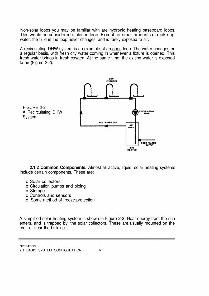
A recirculating DHW system is an example of an open loop. The water changes ona regular basis, with fresh city water coming in whenever a fixture is opened. Thisfresh water brings in fresh oxygen. At the same time, the exiting water is exposedto air (Figure 2-2).
FIGURE 2-2A Recirculating DHWSystem
2.1.2 Common Components. Almost all active, liquid, solar heating systemsinclude certain components. These are:
o Solar collectorso Circulation pumps and pipingo Storageo Controls and sensorso Some method of freeze protection
A simplified solar heating system is shown in Figure 2-3. Heat energy from the sunenters, and is trapped by, the solar collectors. These are usually mounted on theroof, or near the building.
OPERATION
2.1 BASIC SYSTEM CONFIGURATION 6

8/14/2019 Navy Maint. & Op of Active Solar Heating Sy
http://slidepdf.com/reader/full/navy-maint-op-of-active-solar-heating-sy 23/277

8/14/2019 Navy Maint. & Op of Active Solar Heating Sy
http://slidepdf.com/reader/full/navy-maint-op-of-active-solar-heating-sy 24/277
Whenever the collectors are warmer than the storage, the control turns on the pumpto gather solar energy. If the collectors are cooler than storage, the pumps remainoff. Predetermined temperature differences, called differentials, are chosen by thesystem designer.
All solar heating systems share other characteristics. For example, collector pipingshould always deliver cool liquid to the bottom of the collectors. The heated fluidshould be removed from the top. This takes advantage of the natural inclination ofthe warmed liquid to rise.
Most collector piping is designed to flow through multiple collectors in parallel, ratherthan one after the other in series. Because solar collectors operate at relatively lowtemperatures, this method allows them to operate as efficiently as possible.
Finally, piping delivers and picks up fluid from diagonally opposite corners of a groupof collectors, to be sure the liquid flows evenly through all the collectors (Figure 2-4).
FIGURE 2-4A Properly Piped Flat-Plate Collector Array.
Most collectors havethe four ports asshown, to simplify
correct piping.
2.1.3 Common Load Connections, The most common uses (“loads”) forthe energy stored in the storage tank are for domestic hot water (DHW), processwater heating, space heating, space cooling and swimming pool heating.
Domestic Hot Water
In DHW applications, the storage tank is usually installed in the cold water supply.The cold supply is "pre-heated” with solar energy before a standard, “back-up” or“auxiliary,” water heating system receives it. If the solar system supplies adequateheat, the auxiliary system remains off. If the solar system cannot supply the
OPERATION
2.1 BASIC SYSTEM CONFIGURATION 8

8/14/2019 Navy Maint. & Op of Active Solar Heating Sy
http://slidepdf.com/reader/full/navy-maint-op-of-active-solar-heating-sy 25/277
required heated water, the auxiliary system boosts the water temperature the rest ofthe way up to the desired temperature (Figure 2-5).
FIGURE 2-5Solar Storage Tank in
Series With DHWAuxiliary Heater
In either case, no other controls or valves are needed. The solar DHW preheatingsystem in series with an auxiliary heater is the most common solar heatingapplication. The cold water supply is almost always lower in temperature than thesolar storage tank, so solar energy can almost always be utilized.
Process Water Heating
Process water heating with solar systems is almost identical to domestic waterheating. One difference is the larger size of the system. If the process requires hightemperature water, evacuated tube collectors, which operate more efficiently at hightemperatures, may be used.
Some systems use no storage, but add the solar heat to the water as it is brought in.This approach is most common when the solar system is fairly small compared tothe size of the load.
OPERATION
9 2.1 BASIC SYSTEM CONFIGURATION

8/14/2019 Navy Maint. & Op of Active Solar Heating Sy
http://slidepdf.com/reader/full/navy-maint-op-of-active-solar-heating-sy 26/277
Space Heating
The two basic types of “traditional” space heating systems are:
o Air
o Water (hydronic).
In forced air heating systems, the air entering the heating system (the return air) isat room temperature. When the solar heated water is warmer than this return air,solar heat is introduced. A duct coil is used to transfer the solar heat into the returnair before it enters the heating system.
If solar energy alone is sufficient to maintain the room at the thermostat setpoint, theauxiliary system remains off. If the room temperature continues to drop, theauxiliary system boosts the air up to a higher temperature. The auxiliary system canbe a gas or oil burner, or electric coils.
Even when the auxiliary system is on, the solar coil can still preheat the return air,as long as the water temperature is higher than the return air temperature.
A two-stage thermostat usually controls the two heat sources. Stage one (the pumpdelivering solar-heated water) is usually allowed to stay on when stage two (theback-up heater) comes on (Figure 2-6).
FIGURE 2-6A Forced Air HeatingSystem
OPERATION
2.1 BASIC SYSTEM CONFIGURATION 10

8/14/2019 Navy Maint. & Op of Active Solar Heating Sy
http://slidepdf.com/reader/full/navy-maint-op-of-active-solar-heating-sy 27/277
When a typical boiler is running in hydronic systems, the water returning from spaceheaters (AHU, unit heaters, baseboard elements, radiators or others) may bewarmer than the water in the solar storage tank. For this reason, the solar tank andthe auxiliary boiler are installed in parallel.
The solar tank is given the first chance to meet the heating load. If it cannotmaintain the desired temperature, the water flow is diverted through the auxiliaryboiler. Solar energy is not used for preheating, and the two systems performindependently (Figure 2-7).
Again, a two stage thermostat is used, but stage one is cut off whenever stage twocomes on (Figure 2-7).
FIGURE 2-7A Hydronic Heating
System
Space Cooling
Solar heat is used for space cooling with, absorption chillers. These chillers useheat energy to drive the refrigeration cycle, rather than electrical or mechanicalenergy. These systems require fairly high temperatures (160°F-200°F), so they useeither very efficient flat-plate or evacuated tube collectors.
In a solar cooling system, the solar tank and the auxiliary boiler are installed inparallel. This is because when the auxiliary boiler is operating, the water returningfrom the generator is almost always warmer than the water in the solar storage tank.
OPERATION
11 2.1 BASIC SYSTEM CONFIGURATION

8/14/2019 Navy Maint. & Op of Active Solar Heating Sy
http://slidepdf.com/reader/full/navy-maint-op-of-active-solar-heating-sy 28/277
The solar tank is given the first chance to meet the cooling load. If it is not at a highenough temperature, the water returning from the generator is diverted through theauxiliary boiler instead. Solar energy is not used for preheating, and the twosystems are completely independent.
Another way to provide back-up is to install a mechanical or electrical chiller, inparallel with the solar absorption chilling unit. In this case, an auxiliary boiler is notused in the loop with the absorption chiller (Figure 2-8).
FIGURE 2-8An AbsorptionCooling System
Notice that both typesof back-up arepictured, but only oneis normally used.
Swimming Pool Heating
In pool heating, the pool itself functions as the storage medium (Figure 2-9). If thepool is outside, it is normally not used during the winter. During the summer monthsthere is a relatively small temperature difference between the pool and the airaround it.
OPERATION
2.1 BASIC SYSTEM CONFIGURATION 12

8/14/2019 Navy Maint. & Op of Active Solar Heating Sy
http://slidepdf.com/reader/full/navy-maint-op-of-active-solar-heating-sy 29/277
This allows the solar collectors to be very simple. Plastic, rubber or metal absorbersare secured to a roof or rack. No insulation, frame or glazing is necessary.
Pool water flows either directly through the collectors or through a heat exchanger inthe solar loop. After solar heat is added, an auxiliary heater may be used to furtherboost the water temperature.
The pool filter pump is normally set to run during the daylight hours. When the solarcontrol decides the collectors are warmer than the pool water, a valve systemdiverts pool water through the collectors.
Indoor pools used throughout the entire year typically use an indirect system. Thecollectors are standard glazed flat-plate units, and usually a non-freezing fluid isused in the collector loop. A heat exchanger, with stainless steel or copper-nickelpassages for the pool water, transfers the solar heat into the pool.
FIGURE 2-9A Pool Heating
System
OPERATION
13 2.1 BASIC SYSTEM CONFIGURATION
8/14/2019 Navy Maint. & Op of Active Solar Heating Sy
http://slidepdf.com/reader/full/navy-maint-op-of-active-solar-heating-sy 30/277
2.2 BASIC CONFIGURATION OF CLOSED-LOOP SYSTEMS
Closed-loop systems use a relatively small pump to move a non-freezing fluidbetween the solar collectors and a heat exchanger. The heat exchanger, installed ina heated space, transfers the heat from the non-freezing fluid to water.
This water is circulated between the heat exchanger and the storage tank byanother relatively small pump. The heat exchanger, pumps and storage tank are allnormally installed in a heated space.
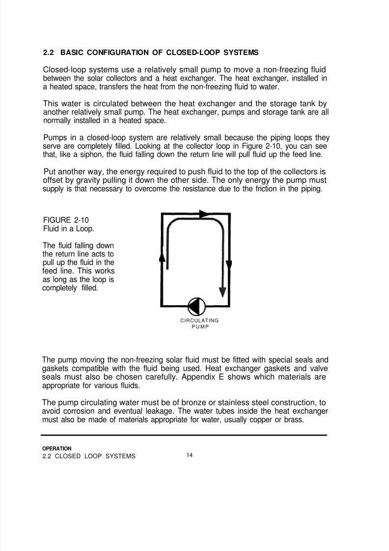
Pumps in a closed-loop system are relatively small because the piping loops theyserve are completely filled. Looking at the collector loop in Figure 2-10, you can seethat, like a siphon, the fluid falling down the return line will pull fluid up the feed line.
Put another way, the energy required to push fluid to the top of the collectors isoffset by gravity pulling it down the other side. The only energy the pump mustsupply is that necessary to overcome the resistance due to the friction in the piping.
FIGURE 2-10Fluid in a Loop.
The fluid falling downthe return line acts topull up the fluid in thefeed line. This worksas long as the loop is
completely filled.
CIRCULATING
P U M P
The pump moving the non-freezing solar fluid must be fitted with special seals andgaskets compatible with the fluid being used. Heat exchanger gaskets and valveseals must also be chosen carefully. Appendix E shows which materials are
appropriate for various fluids.
The pump circulating water must be of bronze or stainless steel construction, toavoid corrosion and eventual leakage. The water tubes inside the heat exchangermust also be made of materials appropriate for water, usually copper or brass.
OPERATION
2.2 CLOSED LOOP SYSTEMS 14

8/14/2019 Navy Maint. & Op of Active Solar Heating Sy
http://slidepdf.com/reader/full/navy-maint-op-of-active-solar-heating-sy 31/277
Closed-loop systems require several special components. (Figure 2-11) One ofthese is an expansion tank in the collector loop, to compensate for the expansionand contraction of the solar fluid as it is heated and cooled.
Another special component is a check valve. When the fluid in the collectors is cold(usually on winter nights), it becomes more dense and drops to the bottom of thecollector loop. Warmer solar fluid from inside the building rises to the top of thecollectors.
Eventually, all the solar fluid is slowly flowing in reverse through the system. Thischilling process can start another similar flow in the water loop between the heatexchanger and the storage tank. The final result is that heat from the storage tankescapes through the solar collectors to the outside. The check valve prevents this“reverse thermosiphoning.”
FIGURE 2-11A Closed-Loop Solar
Heating System
15
OPERATION
2.2 CLOSED LOOP SYSTEMS

8/14/2019 Navy Maint. & Op of Active Solar Heating Sy
http://slidepdf.com/reader/full/navy-maint-op-of-active-solar-heating-sy 32/277
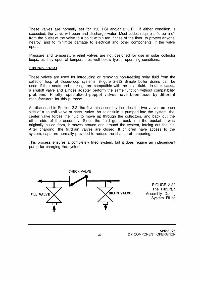
Finally, closed-loop systems require a fill/drain assembly to allow adding the solarfluid while removing air. Normally, this assembly consists of two boiler drains (orhose adapters with shutoff valves) on each side of a shutoff valve. In many cases,the check valve is used between the fill/drain ports in place of a shutoff valve.
Because collectors in a closed-loop system do not need to drain themselves on aregular basis, the location of the collectors relative to the rest of the system is notcritical. Compare this to other types of systems, where the location of the collector iscritical to proper system performance.
2.3 BASIC CONFIGURATION OF DRAINBACK SYSTEMS
Drainback systems use water as the collector fluid. The collectors and exposedpiping must be installed so proper draining is possible to avoid freezing.
Looking at Figure 2-12, you can see how the water from the collectors drains backinto a reservoir tank whenever the solar loop pump is turned off. The reservoir tankis large enough to accept the volume of water held in the collectors and exposedpiping.
When solar energy is available for collection, the solar loop pump pushes water upthe system to the top of the collectors, where it drops back into the reservoir to bepumped back up again.
FIGURE 2-12A Drainback SolarHeating System
OPERATION
2.3 DRAINBACK SYSTEMS 16

8/14/2019 Navy Maint. & Op of Active Solar Heating Sy
http://slidepdf.com/reader/full/navy-maint-op-of-active-solar-heating-sy 33/277

8/14/2019 Navy Maint. & Op of Active Solar Heating Sy
http://slidepdf.com/reader/full/navy-maint-op-of-active-solar-heating-sy 34/277
When freezing conditions are encountered, a control valve in the collector loopshuts off the water pressure to the collectors and exposed piping. The valve allowsthe water in the collectors to escape to a drain. In larger systems, three or moresolenoid valves replace the single control valve used for residential applications.
Currently available collector loop control valves are typically not reliable. If water isleft in the collectors during freezing conditions, they will probably be ruined. For thisreason, draindown systems are not known for their high reliability in climates withfrequent freezes.
2.5 BASIC CONFIGURATION OF THERMOSIPHON SYSTEMS
If solar collectors are filled with water and exposed to the sun, the water will heat up,become less dense, and try to rise. If the outlet of the collectors goes up to astorage tank, the heated water can flow up into the top of the tank.
If the cooler bottom of the tank is piped back to the inlet of the collectors, a flow ofwater will start. This “thermal siphon” can move enough water through thecollectors to heat the contents of a properly sized storage tank. (Figure 2-14)
This system is called a "thermosiphon” system. The collectors, piping and tank areall outside and filled with water. Heat losses can be significant, and the potential forfreezing exists. For this reason, this system is used only in areas which rarely have
FIGURE 2-14A ThermosiphonSystem
OPERATION
2.5 THERMOSIPHON SYSTEMS 18

8/14/2019 Navy Maint. & Op of Active Solar Heating Sy
http://slidepdf.com/reader/full/navy-maint-op-of-active-solar-heating-sy 35/277
freezing temperatures, or during the summer months. If used only in summer, thesystem is drained in the fall.
The heated water is usually for domestic hot water as described in Section 2.1.3.
2.6 BASIC CONFIGURATION OF INTEGRATED COLLECTOR-STORAGESYSTEM
Another system appropriate only for areas or seasons without freezing temperaturesis the integrated collector-storage system. These are sometimes called “ICS”
systems or “breadbox” solar water heaters.
The collector and storage are all in one unit. Typically, an uninsulated storage tankis enclosed in a well-insulated box with one glazed side. (Figure 2-15)
The sun strikes and warms the tank and water. The heated water is usually used topreheat domestic hot water as described in Section 2.1.3.
FIGURE 2-15An ICS System
OPERATION
19 2.6 ICS SYSTEMS

8/14/2019 Navy Maint. & Op of Active Solar Heating Sy
http://slidepdf.com/reader/full/navy-maint-op-of-active-solar-heating-sy 36/277
2.7 COMPONENT OPERATION
2.7.1 Solar Collectors. Because of the effects of the earth’s atmosphere,three ways exist for solar energy to arrive at the solar collectors. The first way is
straight through the atmosphere. On the average, 27% of the amount that wasavailable above the atmosphere arrives by this method. Because it travels directlyto the surface, this energy is called “direct” or “beam” radiation. (Figure 2-16)
The second type of solar energy at the earth’s surface is called “diffuse” or“scattered” radiation. This energy travels in a series of collisions with dust, watervapor and other particles in the atmosphere before arriving at the surface. Thisrepresents about 16% of the amount available above the atmosphere. Finally, solarenergy reflected from the surface of the earth is sometimes available, averaging 5%of what was available. The rest is absorbed or “reflected” by the atmosphere, and isunavailable for collection.
FIGURE 2-16Direct, Diffuse andReflected SolarRadiation
Flat-plate and evacuated tube solar collectors can collect all components of thesun’s energy. Of the two, flat-plate types are the most-used type of collectors.
The typical “liquid-cooled” flat-plate collector consists of a black absorber plate withtubes running through or attached to it to take the collected heat away. Above thissurface is a glazing, usually glass, to help trap the heat. A frame holds the entire
package together, and usually includes some provision for mounting. Insulationsurrounds the absorber to retard the loss of heat from the collector. (Figure 2-17)
OPERATION
2.7 COMPONENT OPERATION 20

8/14/2019 Navy Maint. & Op of Active Solar Heating Sy
http://slidepdf.com/reader/full/navy-maint-op-of-active-solar-heating-sy 37/277
Flat-plate and evacuated tube collectors operate by the “greenhouse effect.” Asseen in Figure 2-17, the heat energy from the sun is in short waves, which maketheir way easily through the molecules of the glazing material. Once inside theystrike, and are absorbed by, the black absorber plate. Fluid flowing through theabsorber passageways carries the heat away.
Heat energy attempting to re-radiate from the absorber does so in much longerwaves than the original incoming energy, and does not move back out through theglazing. In addition, most absorbers are coated with a “selective” surface whichabsorbs large percentages of available heat, and re-radiates small amounts.
FRAME
FIGURE 2-17A Typical Flat-plate
Solar Collector
Evacuated tube collectors further reduce heat loss by surrounding the hot absorberwith a vacuum. This eliminates heat loss by convection (heat movement involvingthe warming and lifting of a gas or liquid). The vacuum serves as the insulation.The glass tube functions as the frame and the glazing.
21
OPERATION
2.7 COMPONENT OPERATION

8/14/2019 Navy Maint. & Op of Active Solar Heating Sy
http://slidepdf.com/reader/full/navy-maint-op-of-active-solar-heating-sy 38/277
The vacuum tubes used are either single wall or double wall. Single wall tubes arebuilt with a small absorber plate in the vacuum. Double wall tubes are similar tothermos bottles, with the vacuum between the two tube walls. The absorber insidethe inner tube is not in a vacuum. (Figure 2-18)
Most evacuated tube collectors are made up of several tubes spaced apart toreduce the total collector cost. To catch solar energy which falls between the tubes,polished metal reflectors are used to direct solar energy into the back sides of thetubes.
FIGURE 2-18Single andDouble WallEvacuated TubeCollectors
SINGLE WALL DOUBLE WALL
Pool Collectors
Collectors used for heating swimming pool water operate at relatively lowtemperatures during fairly warm times of the year. Consequently, the heat loss fromthe collector will not be great under these conditions.
OPERATION
2.7 COMPONENT OPERATION 22

8/14/2019 Navy Maint. & Op of Active Solar Heating Sy
http://slidepdf.com/reader/full/navy-maint-op-of-active-solar-heating-sy 39/277
For this reason, they are nothing but a plastic or metal absorber plate. No frame,
insulation or glazing is used. (Figure 2-1 9)
Indoor pools used throughout the entire year typically use an indirect system. The
collectors are standard glazed flat-plate units with metal absorbers.
FIGURE 2-19An Unglazed Pool
Heating SolarCollector
2.7.2 Pumps. The wetted components of pumps used for moving water arenormally constructed from bronze or stainless steel. These materials do notdeteriorate in water, do not contaminate the water and are compatible with the otherpiping system materials normally used. No special seals or gaskets are required.
Pump components in contact with non-freezing solar fluids are normally made ofcast iron or steel. Special gaskets and seals are always required. See Appendix Efor a listing of fluids and materials compatibility. (Table 2-1)
For applications requiring a small (1/35 to 1/2 hp) circulating pump, the typical unitis a “wet rotor” type. (Figure 2-20) The moving part of the pump motor, the rotor, issurrounded by water. During operation, part of the water being pumped acts as alubricant and coolant for the motor. Wet rotor pumps require no other lubrication ormaintenance, other than periodic inspection.
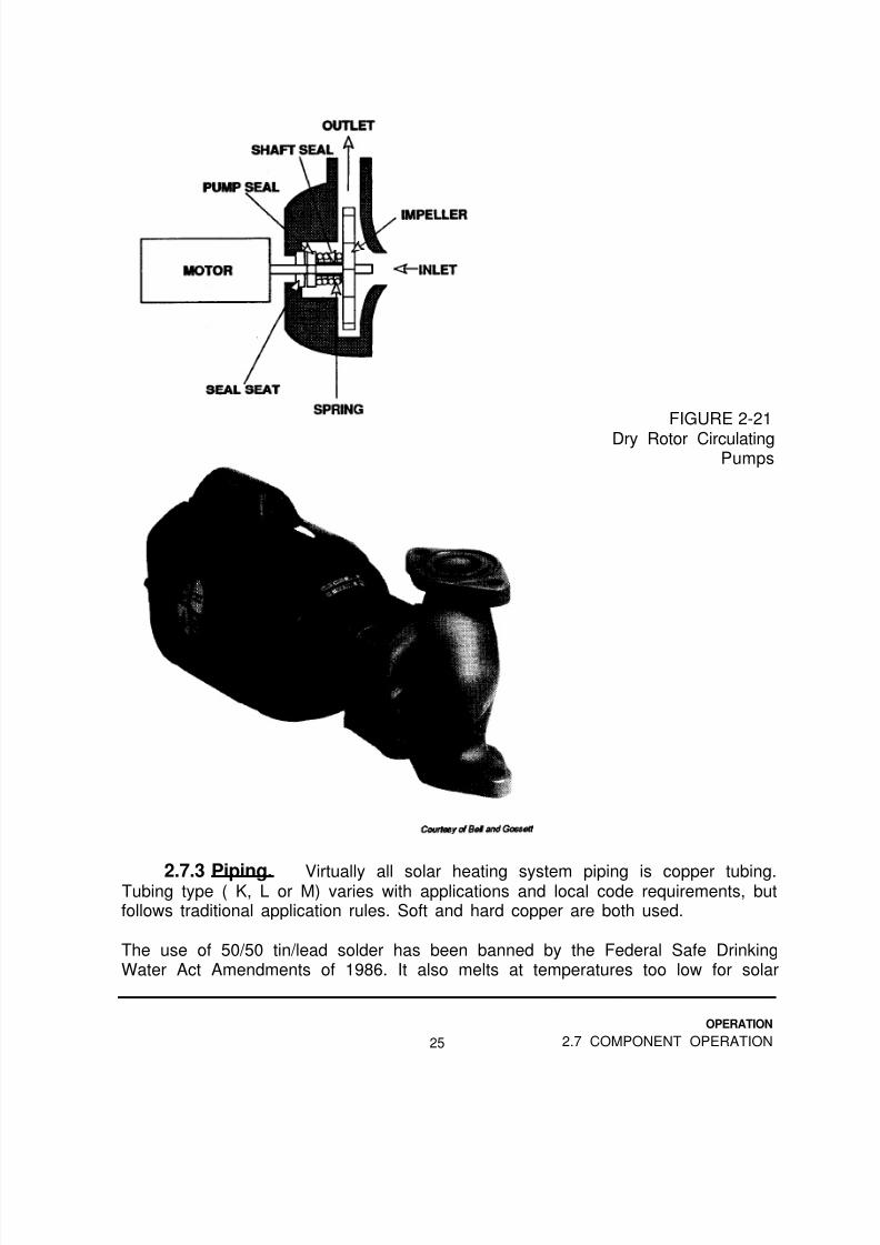
Larger systems may use a number of small wet rotor pumps ganged together, butthe usual choice is one large pump of traditional design. (Figure 2-21) Because themotor and pump are physically separated, periodic lubrication is usually required,and inspection procedures include checking for shaft alignment and bearing wear.
23
OPERATION
2.7 COMPONENT OPERATION

8/14/2019 Navy Maint. & Op of Active Solar Heating Sy
http://slidepdf.com/reader/full/navy-maint-op-of-active-solar-heating-sy 40/277
FIGURE 2-20Wet Rotor CirculatingPumps: Cartridge-Type (left) andMagnetic Drive-Type(right).
TABLE 2-1: Pump Application Guide
Application Typical Choice
Potable water, underpressure
Water, no pressure Can be cast iron or steel,i.e. drainback can be wet or dry rotor,collector loop usually low flow, high head
Non freezing liquid,under pressure, (i.e.closed-loop collectorloop
Bronze or stainless steel,can be wet or dry rotor,usually high flow, low head
Usually cast iron, can bewet or dry rotor, usuallyhigh flow, low head
OPERATION
2.7 COMPONENT OPERATION 24
8/14/2019 Navy Maint. & Op of Active Solar Heating Sy
http://slidepdf.com/reader/full/navy-maint-op-of-active-solar-heating-sy 41/277
FIGURE 2-21
Dry Rotor CirculatingPumps
2.7.3 Piping. Virtually all solar heating system piping is copper tubing.Tubing type ( K, L or M) varies with applications and local code requirements, butfollows traditional application rules. Soft and hard copper are both used.
The use of 50/50 tin/lead solder has been banned by the Federal Safe DrinkingWater Act Amendments of 1986. It also melts at temperatures too low for solar
OPERATION
25 2.7 COMPONENT OPERATION

8/14/2019 Navy Maint. & Op of Active Solar Heating Sy
http://slidepdf.com/reader/full/navy-maint-op-of-active-solar-heating-sy 42/277
heating systems. 95/5 tin/antimony is normally used on most joints. 96/4 tin/silveris recommended for joints involving bronze to avoid leaching the zinc from fittings.
In loops containing fresh water (e.g., potable water), copper, brass, bronze orstainless steel are normally the only appropriate materials. If galvanized piping
already exists, it is necessary to use dielectric unions to isolate different metals.
In loops containing non-freezing solar fluids, or water which is never exposed tooxygen (e.g., the collector loops or closed-loop and drainback systems), smallamounts of cast iron or steel can be part of a copper piping system. These arenormally the wetted components of pumps, expansion tanks, etc.
Aluminum should never be piped into a system with copper, but if it is, special stepssuch as dielectrics and getter columns must be used.
2.7.4 Solar Fluids, The best fluid available for moving the heat from solarcollectors is water. Unfortunately, when water is exposed to freezing temperatures itbecomes solid and expands, two undesirable characteristics.
Special non-freezing fluids have been developed for solar applications. The threetypes typically used are:
o Glycol/Water mixtureso Synthetic oilso Silicone oils
These materials have different characteristics, but they all have one thing in
common, their specific heats and thermal conductivities are lower than water. Thisresults in higher pump and heat exchanger requirements and costs.
CAUTION
Once a system has been filled with a particular type of solar fluid, itshould always be recharged with the same material.
Glycols
Glycols are either ethylene glycol or propylene glycol, usually in a 50/50 mixture withdistilled or demineralized water. Special inhibitors are added to help prevent thefluid from becoming corrosive.
OPERATION
2.7 COMPONENT OPERATION 26
8/14/2019 Navy Maint. & Op of Active Solar Heating Sy
http://slidepdf.com/reader/full/navy-maint-op-of-active-solar-heating-sy 43/277
Propylene glycol is classified as non-toxic, while ethylene glycol is toxic. Thisdifference is critical to occupant safety. Generally, a toxic solar fluid should only beused whenever the heat exchanger is of double wall construction. If a single wall
exchanger is used, a non-toxic fluid should be used. This is particularly importantwhen the storage fluid is potable water, as with a DHW system.
Toxic fluids should also be stored and handled carefully. Access by children andpets should be avoided.
Because the glycols eventually break down chemically, annual testing is required.
Piping systems to be filled with glycol mixtures can be pressure tested and flushedwith water before the glycol/water mixture is put in the system.- It is important toremove “hung-up” water during the filling process to avoid diluting the fluid.
Pump gaskets and seals, expansion tank diaphragms, valve seals and seats and
other elastomers and plastics must be compatible with glycols. Typical acceptablematerials are EPDM, Hydrin, Viton and Teflon. Thread sealants must be Teflon-based. See Appendix E for a complete listing of fluids and materials compatibility.
Glycol/water mixtures have a lower surface tension than water. This results in a“leakier” fluid, making tight joints more important than usual.
Synthetic Oils
The major advantage of synthetic oils is their almost unlimited lifetime.Furthermore, unless the fluid leaks out of the piping system, virtually no
maintenance is required. Toxicity is low as well.
The specific heat and thermal conductivity of synthetic oils is considerably lowerthan water. These factors increase pumping and heat exchanger requirements andcosts. Synthetic oils attack more materials than the glycols, and can damageroofing materials if spilled. Materials resistant to degradation include Teflon, Vitonand Hydrin. Thread sealants must be Teflon-based. Appendix E contains acomplete compatibility listing.
The surface tension of synthetic oils is very low, resulting in a fluid which is evenmore difficult to confine in piping.
Synthetic oils must never be mixed with water, and must be introduced into aperfectly dry piping system. Water must never be used for pressure testing orflushing.
OPERATION
27 2.7 COMPONENT OPERATION

8/14/2019 Navy Maint. & Op of Active Solar Heating Sy
http://slidepdf.com/reader/full/navy-maint-op-of-active-solar-heating-sy 44/277
Silicone Oils
Silicones have many of the characteristics of synthetic oils. Differences include aneven lower surface tension, so they are even harder to confine. Thread sealantsmust be fluorosilicone-based, or joint failure is inevitable. Silicone oil is veryexpensive, typically 3 to 10 times the cost of other fluids.
Silicone oils must never be mixed with water, and must always be introduced intoclean, dry piping systems. Water must never be used for pressure testing orflushing.
2.7.5 Heat Exchangers, The purpose of a solar heat exchanger is to transferthe collected solar heat from a non-freezing fluid into the water in the storage tank.Heat exchangers used in solar heating systems are typically one of three types:
o Tube-in-tubeo Coil-in- tanko Shell and tube
Tube-in-Tube
Tube-in-tube heat exchangers are typically used on smaller systems (20 sq. ft. to600 sq. ft. of collector area). As their name implies, they consist of a tube within atube. One fluid moves through the innermost tube, and the other fluid moves in theopposite direction through the space between the outer and inner tubes.(Figure 2-22)
In many cases, two tube walls are between the fluids, affording double wallprotection to the water being heated. In most double wall exchangers of this type,small passageways between the two walls provide leak detection and prevent anypossibility of contamination.
Some designers choose to have solar fluid in the innermost tube, and others preferto use it for water. Be sure you know which design is used for a particular systembefore undertaking repairs.
Most manufacturers add small fins to the wetted surfaces of tube-in-tube heatexchangers. This increases the surface area and keeps the fluid in turbulent flow,resulting in improved heat transfer rates.
OPERATION
2.7 COMPONENT OPERATION 28

8/14/2019 Navy Maint. & Op of Active Solar Heating Sy
http://slidepdf.com/reader/full/navy-maint-op-of-active-solar-heating-sy 45/277
FIGURE 2-22A Tube-in-TubeHeat Exchanger
Coil-in-Tank
Another heat exchanger used for small systems is the coil-in-tank. (Figure 2-23) Inthis type, a coil is immersed in the storage tank itself. Heated solar fluid is pumpedthrough the coil. The tank water surrounding the coil is continually heated and risesby natural convection.
FIGURE 2-23A Coil-in-Tank
Heat Exchanger
Tanks fitted with heat exchangers are made with both double and single wallexchangers. Be sure to use a non-toxic solar fluid whenever the heat exchanger issingle wall.
Most coil-in-tank units feature a finned outer surface to improve heat transfer. Inmany cases, the inside of the coil is textured to further improve performance.
OPERATION
29 2.7 COMPONENT OPERATION

8/14/2019 Navy Maint. & Op of Active Solar Heating Sy
http://slidepdf.com/reader/full/navy-maint-op-of-active-solar-heating-sy 46/277

8/14/2019 Navy Maint. & Op of Active Solar Heating Sy
http://slidepdf.com/reader/full/navy-maint-op-of-active-solar-heating-sy 47/277
Glass Lined
The glass or porcelain lined tank is the most widely used. (Figure 2-25) It isavailable in stock standard sizes from a few gallons to 120 gallons. Larger sizes, upto thousands of gallons, can be constructed on a custom-made basis. In manycases it is more cost-effective to use two or more “standard” tanks rather than onelarge “custom” one. Many manufacturers offer tanks with internal coils.
A lining is necessary, because a large amount of oxygen is dissolved in the storagewater. In DHW systems, new water, with new supplies of dissolved oxygen, isintroduced every day. This dissolved oxygen makes the water corrosive tountreated steel.
Other water conditions increase its corrosiveness. In some areas, the pH of thewater is low. This acidic condition accelerates corrosion. Sometimes the amount ofdissolved solids in the water is high, which also increases the problem.
If any gaps in the glass lining exist, the water will attack the bare steel. In a matterof months, a leak will occur, even in areas with “good” water.
FIGURE 2-25Glass Lined
Storage Tank
OPERATION
31 2.7 COMPONENT OPERATION

8/14/2019 Navy Maint. & Op of Active Solar Heating Sy
http://slidepdf.com/reader/full/navy-maint-op-of-active-solar-heating-sy 48/277
Anode rods are used to protect exposed tank metal from corrosion. If two differentmetals are in contact with each other and water, the less “noble” of the two metalswill corrode first. Once the first metal is completely eaten away, the second metalwill begin to corrode.
The anode rod is sometimes called a “sacrificial anode,” because it is sacrificed toprotect the steel of the tank. If the anode is never allowed to completely dissolve, itwill continue to protect the tank. (Figure 2-25)
Stone Lined
Another approach to tank wall protection is to apply a thick lining of low sulfurcement to the inside. After the tank is baked, a thick stone lining completely coversthe tank walls. This lining is very hard to break.
Normally, no anode rod is used on stone lined tanks. This eliminates one
maintenance step. However stone lined tanks weigh around 50% more than glass-lined tanks. (Figure 2-26)
Stone lined tanks are readily available in standard sizes of 40 to 120 gallons. Mostmanufacturers offer tanks with an internal heat exchanger coil.
FIGURE 2-26Stone LinedStorage Tank
STONE LINING
STEEL TANK WALL
INSULATION
PAINTED STEEL
OUTER SHELL
OPERATION
2.7 COMPONENT OPERATION 32

8/14/2019 Navy Maint. & Op of Active Solar Heating Sy
http://slidepdf.com/reader/full/navy-maint-op-of-active-solar-heating-sy 49/277

8/14/2019 Navy Maint. & Op of Active Solar Heating Sy
http://slidepdf.com/reader/full/navy-maint-op-of-active-solar-heating-sy 50/277
For shutoff purposes, gate valves or ball valves should be used. (figure 2-27) Globevalves, because of their high resistance to flow, should never be used in any part ofthe system.
Tanks, heat exchangers, the cold water supply, and banks of collectors are typicalcandidates for shutoff valves. Pumps can be isolated as well, using either separatevalves or isolation flanges
Isolation valves should not be used on solar collector arrays unless a pressure reliefvalve is in the piping between valves.
Balancing Valves
An ideal collector array is piped so that all the collectors receive an equal flowautomatically. However, sometimes it is necessary to install balancing valves in thecollector piping to accomplish this.
FIGURE 2-27A Gate Valve (left)and a Ball Valve
(right)
Balancing valves should be ball valves, and should be installed in the inlet line at thetop of a group of collectors. Every group of panels should also have a thermometer
or the equivalent installed in its outlet. (Figure 2-28) When all the outlet pipingtemperatures are equal, the flows are properly balanced between collector groups.
Check Valves
Check valves allow fluid flow in only one direction. They are used in closed-loopand draindown systems to prevent heat loss at night by reverse thermosiphoning.
OPERATION
2.7 COMPONENT OPERATION 34

8/14/2019 Navy Maint. & Op of Active Solar Heating Sy
http://slidepdf.com/reader/full/navy-maint-op-of-active-solar-heating-sy 51/277
FIGURE 2-28Balancing Valves
and ThermometersInstalled On a
Collector Array
The best choice for this application is a spring-loaded check valve. Make sure the
seat and seals are appropriate for the fluid being used. (Figure 2-29)
It is also worth noting that tests of large numbers of check valves have found widevariations in opening pressures and high overall failure rates. For this reason, it isimportant to inspect check valves for proper operation at every system inspection,as explained in the inspection chapter, Section 3.1.3.
Pressure Relief Valves
These valves (sometimes called PRV’s) are used only in the collector loop ofclosed-loop systems. Since they only respond to pressure changes, they should notbe used on pressurized water (city water) lines or tanks. A strong internal spring
keeps the valve closed until the system pressure exceeds some preset limit.(Figure 2-30)
FIGURE 2-29Swing (left) and
Spring (right) CheckValves
The outlet port of pressure relief valves is piped downward to within 10 in. of thefloor, to protect anyone who happens to be nearby, and to minimize damage toelectrical and other components, should the valve open.
35
OPERATION
2.7 COMPONENT OPERATION

8/14/2019 Navy Maint. & Op of Active Solar Heating Sy
http://slidepdf.com/reader/full/navy-maint-op-of-active-solar-heating-sy 52/277
8/14/2019 Navy Maint. & Op of Active Solar Heating Sy
http://slidepdf.com/reader/full/navy-maint-op-of-active-solar-heating-sy 53/277

8/14/2019 Navy Maint. & Op of Active Solar Heating Sy
http://slidepdf.com/reader/full/navy-maint-op-of-active-solar-heating-sy 54/277
Expansion Tanks
Expansion tanks are normally used in the collector loop of closed-loop systems.Occasionally they are found in the cold water supply to storage tanks, but only if abackflow preventer or check valve is also in that line.
CAUTION
Whenever an expansion tank is installed in a loop witha pump, it must be on the suction side of thepump. (Figure 2-33) Installation of an expansion tankon the discharge side of the pump can result in pumpcavitation and damage.
Because fluids are not compressible, expansion tanks are needed to maintain afairly stable system pressure. Without one, a closed piping system undergoingtemperature changes would fluctuate from zero pounds to many hundreds ofpounds of pressure.
Expansion tanks for solar fluids are normally constructed of raw. or galvanizedsteel. (Figure 2-34) Some have a flexible internal diaphragm maintaining a separateair cushion. (Figure 2-35) Diaphragm-type tanks are preferred for solar applications.The air side of the tank usually has a Schrader valve (similar to the ones used onautomobile tires) to allow checking and changing the air pressure. The air cushion
normally comes pre-charged from the factory at 12 PSI.
FIGURE 2-33Proper ExpansionTank Placement
OPERATION
2.7 COMPONENT OPERATION 38

8/14/2019 Navy Maint. & Op of Active Solar Heating Sy
http://slidepdf.com/reader/full/navy-maint-op-of-active-solar-heating-sy 55/277

8/14/2019 Navy Maint. & Op of Active Solar Heating Sy
http://slidepdf.com/reader/full/navy-maint-op-of-active-solar-heating-sy 56/277
8/14/2019 Navy Maint. & Op of Active Solar Heating Sy
http://slidepdf.com/reader/full/navy-maint-op-of-active-solar-heating-sy 57/277
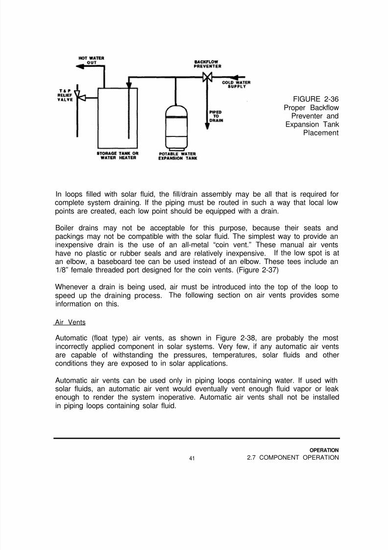
FIGURE 2-36Proper Backflow
Preventer andExpansion Tank
Placement
In loops filled with solar fluid, the fill/drain assembly may be all that is required forcomplete system draining. If the piping must be routed in such a way that local lowpoints are created, each low point should be equipped with a drain.
Boiler drains may not be acceptable for this purpose, because their seats andpackings may not be compatible with the solar fluid. The simplest way to provide aninexpensive drain is the use of an all-metal “coin vent.” These manual air ventshave no plastic or rubber seals and are relatively inexpensive. If the low spot is atan elbow, a baseboard tee can be used instead of an elbow. These tees include an1/8” female threaded port designed for the coin vents. (Figure 2-37)
Whenever a drain is being used, air must be introduced into the top of the loop tospeed up the draining process. The following section on air vents provides someinformation on this.
Air Vents
Automatic (float type) air vents, as shown in Figure 2-38, are probably the mostincorrectly applied component in solar systems. Very few, if any automatic air ventsare capable of withstanding the pressures, temperatures, solar fluids and otherconditions they are exposed to in solar applications.
Automatic air vents can be used only in piping loops containing water. If used withsolar fluids, an automatic air vent would eventually vent enough fluid vapor or leakenough to render the system inoperative. Automatic air vents shall not be installedin piping loops containing solar fluid.
OPERATION
41 2.7 COMPONENT OPERATION
8/14/2019 Navy Maint. & Op of Active Solar Heating Sy
http://slidepdf.com/reader/full/navy-maint-op-of-active-solar-heating-sy 58/277
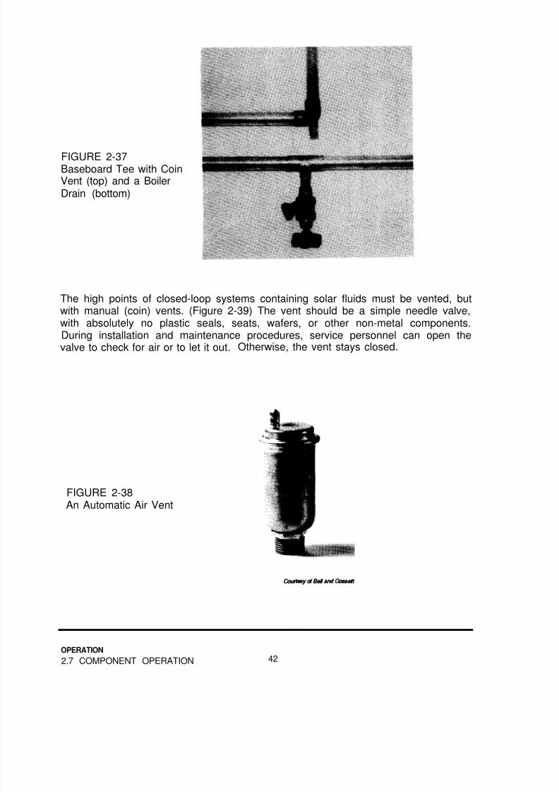
FIGURE 2-37Baseboard Tee with CoinVent (top) and a BoilerDrain (bottom)
The high points of closed-loop systems containing solar fluids must be vented, butwith manual (coin) vents. (Figure 2-39) The vent should be a simple needle valve,with absolutely no plastic seals, seats, wafers, or other non-metal components.During installation and maintenance procedures, service personnel can open thevalve to check for air or to let it out. Otherwise, the vent stays closed.
FIGURE 2-38An Automatic Air Vent
OPERATION
2.7 COMPONENT OPERATION 42

8/14/2019 Navy Maint. & Op of Active Solar Heating Sy
http://slidepdf.com/reader/full/navy-maint-op-of-active-solar-heating-sy 59/277
The high points of draindown and drainback collector loops, and the high point ofstorage water loops should use a high-pressure automatic air vent. The vent mustbe rated for at least 125 PSI, although 150 PSI is better.
The cap on automatic air vents is used to prevent the entry of dust which would clogthe mechanism, so it is never fully tightened.
FIGURE 2-39A Manual Air Vent
The air vent should be constructed of metal. Plastic air vents are not recommended
because catastrophic failure is common.
Air Eliminators
Air eliminators, also called air scoops, are normally used only on the collector loopsof large closed-loop systems. Their internal construction includes vanes to pushentrained air bubbles upward to a holding chamber. When enough bubbles havebeen collected, an automatic air vent at the top of the unit vents the air.(Figure 2-40)
The air vent should allow flow only during startup operations. They must be closedduring normal operation, after all the air has been removed from the system. Again,
be sure the vent is capable of withstanding the solar fluid itself, and the systempressures.
Most air eliminators feature a threaded port on the bottom for the system expansiontank. This is acceptable, but it means the eliminator/vent/expansion tank packagemust be installed on the suction side of the solar pump.
OPERATION
43 2.7 COMPONENT OPERATION

8/14/2019 Navy Maint. & Op of Active Solar Heating Sy
http://slidepdf.com/reader/full/navy-maint-op-of-active-solar-heating-sy 60/277

8/14/2019 Navy Maint. & Op of Active Solar Heating Sy
http://slidepdf.com/reader/full/navy-maint-op-of-active-solar-heating-sy 61/277
FIGURE 2-41A Draindown SystemUsing Three Solenoid
Valves
Special control valves are of a rotary or spool valve type. Both are typically used onsmall systems only, due to their limited flow capacity. Their basic principle ofoperation is identical to the three solenoid valve system. (Figure 2-42)
Draindown control valves usually include a check valve to prevent nighttime heatloss by reverse thermosiphoning. This heat loss can occur on nights warm enough
for the collectors to be filled.
FIGURE 2-42An Automatic
Draindown ControlValve
OPERATION
45 2.7 COMPONENT OPERATION

8/14/2019 Navy Maint. & Op of Active Solar Heating Sy
http://slidepdf.com/reader/full/navy-maint-op-of-active-solar-heating-sy 62/277
Vacuum Breakers
A vacuum breaker remains closed only as long as the system it is piped into haspressure. When the system pressure falls below atmospheric pressure, it opens.Vacuum breakers are used at the top of draindown and drainback systems to allowair to enter the loop to facilitate rapid drainage. They are sometimes installed abovethe cold water inlet of storage tanks and water heaters to eliminate vacuumconditions that could collapse the tanks. (Figure 2-43)
FIGURE 2-43A Vacuum Breaker
As is the case with automatic air vents, no vacuum breaker manufacturer endorsesthe use of their product outside.
Three-Way Diverting Valves
Some space heating applications, particularly those involving hydronic back-up, usemotorized three way valves for automatic control of the distribution of solar heat.The valve must be rated for the water pressure and temperatures expected in thesystem, but these are not normally a problem.
Manual three-way valves (Figure 2-44) are sometimes used to isolate or bypass thestorage or back-up heaters in DHW systems. Because slight amounts of leakageare typical, they cannot be used as shutoff valves for service purposes. However,as an isolation or bypass valve, they are more convenient than a pair of two-way
valves.
OPERATION
2.7 COMPONENT OPERATION 46

8/14/2019 Navy Maint. & Op of Active Solar Heating Sy
http://slidepdf.com/reader/full/navy-maint-op-of-active-solar-heating-sy 63/277
FIGURE 2-44A Manual Three-WayValve
2.7.8 Pipe and Tank Insulation, The most efficient solar heating systemcannot deliver heat it has lost from piping and tanks. System insulation must bethermally adequate, continuous and durable. Regular inspection and maintenanceis necessary to ensure the insulation and jacketing have not been damaged.
Pipe Insulation
At a minimum, all solar piping under 1 inch size (nominal) should be insulated to R-4. All piping 1 inch or larger should be insulated to at least R-6. Exterior piping of
all sizes benefits from insulation to R-7. (Figure 2-45)
Protection from moisture and ultraviolet radiation is necessary for all exteriorinsulation. (Table 2-2)
Polystyrene or polyethylene should never be used for solar applications. Thesematerials melt at a temperature of 165ºF, well below the expected temperature forpiping in most parts of all systems.
OPERATION
47 2.7 COMPONENT OPERATION

8/14/2019 Navy Maint. & Op of Active Solar Heating Sy
http://slidepdf.com/reader/full/navy-maint-op-of-active-solar-heating-sy 64/277
Good insulation practices require the following:
o All exterior joints must be sealed and protected, includingthose between the insulation and collectors, and roofpenetrations.
o Pipes must be supported on the outside of the insulation,using saddles to distribute the piping weight withoutcrushing the insulation.
o Pipe supports must allow piping and insulation to moveduring periods of thermal expansion and contractionwithout tearing the insulation.
TABLE 2-2: Typical Solar Pipe Insulations
Material
Fiber glass
R-value Trade(per in.) Name(s)
4.0 CertainTeed
Notes on use
Must be protectedfrom moisture,
joints are difficultto fabricate,Max. temp. is 300°F
Closed cellflexibleelastomericfoam
3.5 ArmaflexRubatex
May require twolayers, does not needmoisture protection,must have UV pro-tection, max. temp.is 220°F
Closed cellrigidurethaneand poly-isocyanurate
foams
6.5 Solar-7to lnsultek
7.0 lnsulsleeve
Must have UV andmoisture protection,max. temp. is 250°F
OPERATION
2.7 COMPONENT OPERATION 48

8/14/2019 Navy Maint. & Op of Active Solar Heating Sy
http://slidepdf.com/reader/full/navy-maint-op-of-active-solar-heating-sy 65/277
FIGURE 2-45Closed Cell (Top),
Fiber glass (Center),and
Elastomer (Bottom)Insulation
OPERATION
49 2.7 COMPONENT OPERATION

8/14/2019 Navy Maint. & Op of Active Solar Heating Sy
http://slidepdf.com/reader/full/navy-maint-op-of-active-solar-heating-sy 66/277

8/14/2019 Navy Maint. & Op of Active Solar Heating Sy
http://slidepdf.com/reader/full/navy-maint-op-of-active-solar-heating-sy 67/277

8/14/2019 Navy Maint. & Op of Active Solar Heating Sy
http://slidepdf.com/reader/full/navy-maint-op-of-active-solar-heating-sy 68/277
One exception is the collector sensor on pool heating systems. It is not attached tothe collector. It is built and mounted on the roof or rack next to the collectors.Because it has nearly the same thermal characteristics as the collectors, it“impersonates” the collector temperature for the control to use. (Figure 2-48)
Controls and sensors are available in two types: 10K and 3K. These refer to the
resistance the temperatures have at “room” temperature (77°F). A 10K sensor has10,000 ohms resistance at this temperature, a 3K has 3,000 ohms.
FIGURE 2-48A Pool System
Collector Sensor
Normally, the sensors operate at only a few volts. This means sensor wiring isconsidered Class 2, and thus does not require conduit or armor. However, this lowvoltage wiring is susceptible to electrical “noise” from 120, 240 and higher voltagewiring, electric motors, radio transmitters and other sources of RF (radio frequency)noise.
The usual solution to this problem is to maintain adequate distance between thecontrols, sensors and wiring, and the source of noise. If this is not possible,shielded cable is used.
Most controls have a three-position switch with the functions marked “on,” “off,” and“auto.” In the “on” position, the control ignores the sensor signals and operates the
pumps constantly. In the “off” position, the sensor signals are ignored, and thepumps remain off. The “auto” position is used for normal, automatic operation.(Figure 2-49)
OPERATION
2.7 COMPONENT OPERATION 52
8/14/2019 Navy Maint. & Op of Active Solar Heating Sy
http://slidepdf.com/reader/full/navy-maint-op-of-active-solar-heating-sy 69/277
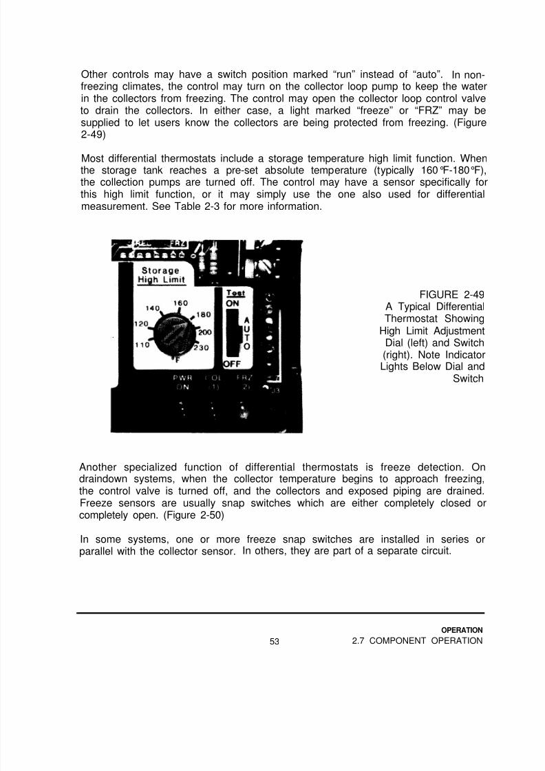
Other controls may have a switch position marked “run” instead of “auto”. In non-freezing climates, the control may turn on the collector loop pump to keep the waterin the collectors from freezing. The control may open the collector loop control valveto drain the collectors. In either case, a light marked “freeze” or “FRZ” may besupplied to let users know the collectors are being protected from freezing. (Figure
2-49)
Most differential thermostats include a storage temperature high limit function. Whenthe storage tank reaches a pre-set absolute temperature (typically 160°F-180°F),the collection pumps are turned off. The control may have a sensor specifically forthis high limit function, or it may simply use the one also used for differentialmeasurement. See Table 2-3 for more information.
FIGURE 2-49A Typical DifferentialThermostat Showing
High Limit AdjustmentDial (left) and Switch(right). Note IndicatorLights Below Dial and
Switch
Another specialized function of differential thermostats is freeze detection. Ondraindown systems, when the collector temperature begins to approach freezing,the control valve is turned off, and the collectors and exposed piping are drained.Freeze sensors are usually snap switches which are either completely closed orcompletely open. (Figure 2-50)
In some systems, one or more freeze snap switches are installed in series orparallel with the collector sensor. In others, they are part of a separate circuit.
OPERATION
53 2.7 COMPONENT OPERATION
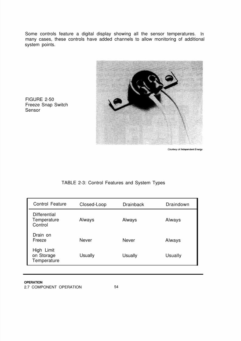
8/14/2019 Navy Maint. & Op of Active Solar Heating Sy
http://slidepdf.com/reader/full/navy-maint-op-of-active-solar-heating-sy 70/277
Some controls feature a digital display showing all the sensor temperatures. Inmany cases, these controls have added channels to allow monitoring of additionalsystem points.
FIGURE 2-50Freeze Snap SwitchSensor
TABLE 2-3: Control Features and System Types
Control Feature Closed-Loop Drainback Draindown
DifferentialTemperatureControl
Always Always Always
Drain on
Freeze Never Never Always
High Limiton Storage Usually Usually UsuallyTemperature
OPERATION
2.7 COMPONENT OPERATION 54

8/14/2019 Navy Maint. & Op of Active Solar Heating Sy
http://slidepdf.com/reader/full/navy-maint-op-of-active-solar-heating-sy 71/277
2.7.10 Gauges. Measurements of two properties are usually necessary;temperature and pressure. Other things can be measured or monitored, but thesetwo are the most critical.
Temperature
Temperatures in solar systems are measured in one of three ways:
o Fixed thermometerso PT plugs or thermometer wells (with movable thermometers)o Electronic sensors (usually thermistors)
Price and accessibility are the usual criteria for deciding which approach to use at aparticular system point. All are sufficiently accurate for normal purposes.
Measuring collector feed and return line temperatures allows service personnel to
confirm solar loop flow, and to get a rough idea of system performance. Moreinformation on this subject is found in Section 4.3.5 in the troubleshooting chapter.Figures 2-51 and 2-52 are examples of two methods of measuring thesetemperatures.
In systems with a pumped storage loop between a heat exchanger and the storagetank, two more temperature measurement points may be appropriate. At aminimum, the storage tank outlet should be equipped with a way to measuretemperature. This allows service personnel to confirm that energy has beentransferred into storage, and is being used.
FIGURE 2-51Insertion
Thermometers withPT Plugs
OPERATION
55 2.7 COMPONENT OPERATION

8/14/2019 Navy Maint. & Op of Active Solar Heating Sy
http://slidepdf.com/reader/full/navy-maint-op-of-active-solar-heating-sy 72/277
FIGURE 2-52Thermometer withInstrument Well
Other candidates for temperature measurement include the feed and return of theauxiliary systems, the feed and return of space heating distribution loops, and thepoints measured by differential thermostat sensors.
Pressure
Pressure measurement is necessary in the collector loop of closed-loop systems. Itis the only practical way to confirm that there is adequate solar fluid for properoperation.
Measuring the pressure on each side of a pump makes it possible to determine theflow rate through the pump. This process is explained in Section 3.1.4 in theinspection, chapter.
Differential pressure measurements can also describe flow rates through heatexchangers, collectors or other components, if the manufacturer can supply flowrate vs. pressure drop information. (Figure 2-53)
Specialized flow setting devices use a restriction of known characteristics withpressure measurement ports on each side. A differential pressure gauge isnormally used to determine and help set the flow rate.
Occasionally, a draindown system will have a pressure gauge in the drained portionof the collector loop. On cold nights, one look at the gauge tells whether or not thewater has drained.
OPERATION
2.7 COMPONENT OPERATION 56

8/14/2019 Navy Maint. & Op of Active Solar Heating Sy
http://slidepdf.com/reader/full/navy-maint-op-of-active-solar-heating-sy 73/277
FIGURE 2-53A Single
Pressure Gaugefor Measuring
Pressure onEither Side of a
Pump
Other Devices
Elapsed time meters are sometimes used to help predict service intervals, andconfirm proper control operation.
BTU meters combine temperature differential and flow rate measurements tocalculate heat flow. These are generally used for monitoring purposes. (Figure 2-54)
Indicator lights are normally included on the differential thermostat to show theavailability of power and when power is being sent to the pumps. Sometimes,remote lights and temperature displays are added to the control to make checkingon the system more convenient.
Pressure alarms have been used to alert service personnel to the need for servicein closed-loop systems. They are not currently in general use.
FIGURE 2-54A BTU Meter System
OPERATION
57 2.7 COMPONENT OPERATION

8/14/2019 Navy Maint. & Op of Active Solar Heating Sy
http://slidepdf.com/reader/full/navy-maint-op-of-active-solar-heating-sy 74/277
2.8 Questions for self-study
Instructions: Choose the one answer you believe is correct. Answers to questionsare in Appendix F.
2-1 Which of these is a closed loop?
a) The water storage loop of a glycol-based solar systemb) A recirculating domestic hot water systemc) A draindown system’s collector loopd) A collector loop filled with synthetic oil
2-2 Which of these is used to stop reverse thermosiphoning in the collector loop?
a) A pump
b) A backflow preventerc) A check valved) An expansion tank
2-3 Which one of these systems uses an expansion tank in the collector loop?
a) A closed-loop systemb) A drainback systemc) A draindown systemd) A pool heating system
2-4 Which one of these systems uses a collector loop control valve in the collector
loop?
a) A closed-loop systemb) A drainback systemc) A draindown systemd) A pool heating system
2-5 The “greenhouse effect” describes which characteristic of glass?
a) It reflects most of the short and long wave radiationb) It lets short wave radiation through better than long wave
c) It allows light through, but not heatd) It only allows radiation good for plant growth through
OPERATION
2.8 QUESTIONS FOR SELF-STUDY5 8

8/14/2019 Navy Maint. & Op of Active Solar Heating Sy
http://slidepdf.com/reader/full/navy-maint-op-of-active-solar-heating-sy 75/277
2-6 Which of these is a toxic solar collector fluid?
a) Distilled waterb) Ethylene glycolc) Propylene glycol
d) Synthetic oil
2-7 Which one is required for a heat exchanger using a toxic fluid to heat domestichot water?
a) Single wall constructionb) Double wall constructionc) Sacrificial anoded) Stainless steel bonnets
2-8 Which of these types of storage tanks will always require a sacrificial anode?
a) Cement linedb) Phenolic resin linedc) Glass linedd) Stone lined
2-9 The high point of a glycol-filled collector loop must have which one of thefollowing?
a) An automatic air ventb) A manual air vent
c) A vacuum breakerd) An expansion tank
2-10 Where should an expansion tank be placed in a closed loop system?
a) On the inlet side of the heat exchangerb) On the inlet side of the collectorsc) On the inlet side of the pumpd) It can be placed anywhere in the loop
59
OPERATION
2.8 QUESTIONS FOR SELF-STUDY

8/14/2019 Navy Maint. & Op of Active Solar Heating Sy
http://slidepdf.com/reader/full/navy-maint-op-of-active-solar-heating-sy 76/277
2-11 Which type of insulation can be used anywhere on a solar system and does notrequire moisture protection?
a) Elastomeric
b) Fiber glassc) Urethane foamd) Polystyrene
2-12 When the temperature of a typical 10K thermistor goes up, what happens?
a) Its resistance increasesb) Its resistance decreasesc) Its voltage increasesd) Its voltage decreases
2-13 What is a device with two temperature sensors and a flow meter called?
a) A differential thermostatb) An aquastatc) A proportional controld) A BTU meter
OPERATION
2.8 QUESTIONS FOR SELF-STUDY 60

8/14/2019 Navy Maint. & Op of Active Solar Heating Sy
http://slidepdf.com/reader/full/navy-maint-op-of-active-solar-heating-sy 77/277
3.0INSPECTION
What You Will Find in This Chapter,
This chapter covers solar system inspection procedures and features a checklist forinspectors. Repair and maintenance information is not in this chapter. Thesesubjects are covered in their own chapters, 5 and 6, respectively.
This chapter, by itself, should provide information required for an Annual ControlInspection. This chapter together with Chapter 6, Preventative Maintenance,provides information needed for a Preventative Maintenance Inspection. Twochecklists are included at the end of this chapter for use in the field.
The information in Appendices A, B and C will be helpful in performing theoperations described in this chapter. Appendix C describes the tools which may berequired. In addition, bring the maintenance and operation manual furnished withthe system, if it is available.
Introduction
Inspection is an important part of any solar service effort. A system inspectionshould be made once a year. Ideally, it is done either in the spring or fall to spotproblems before the weather extremes of summer and winter arrive.
In some cases, inspections are done independently, to determine maintenance andrepair needs. In other cases, inspection and maintenance are performedsimultaneously. In general, they are done together if personnel qualified andequipped to perform maintenance and simple repairs are performing the inspection.
Remember, information on repairing or maintaining these components is found inChapters 5 and 6.
61
INSPECTION
INTRODUCTION
8/14/2019 Navy Maint. & Op of Active Solar Heating Sy
http://slidepdf.com/reader/full/navy-maint-op-of-active-solar-heating-sy 78/277
3.1 INSPECTION PROCEDURES
The following sections are in the same order as the Inspection Checklist near theend of this chapter. It is suggested you read through the procedures before usingthe checklist. This will reduce confusion about what the checklist requires.
3.1.1 Solar Collectors,
Glazings
Collector glazings should be unbroken, clean and without internal condensation.
A broken glazing has a serious effect on collector performance, and should berepaired immediately. The interior of the collector must be protected from theweather.
WARNING!
Even without a glazing, the absorber plate can be hot enough tocause serious burns.
CAUTION
If you cover the broken collector with plastic, be sure tosupport it well enough to keep it from sagging and touching theabsorber plate. Even without a glazing, the plate can get hotenough to melt the plastic onto the plate. Consider using anopaque plastic such as black.
The system can remain operational, unless an object which broke the glazing alsohit the absorber plate hard enough to cause a leak.
Whenever a broken glazing is found, and no obvious cause exists, check thecollector frame dimensions carefully. An out-of-square or otherwise faulty collectorwill repeatedly break glazings during hot weather.
INSPECTION
3.1 INSPECTION PROCEDURES 62

8/14/2019 Navy Maint. & Op of Active Solar Heating Sy
http://slidepdf.com/reader/full/navy-maint-op-of-active-solar-heating-sy 79/277

8/14/2019 Navy Maint. & Op of Active Solar Heating Sy
http://slidepdf.com/reader/full/navy-maint-op-of-active-solar-heating-sy 80/277
Occasionally, sealants, gaskets or even subcomponent labels will outgas. Thisprocess, akin to vaporization, results in gases inside the collector frame. Theycondense on cold surfaces. Unfortunately, this includes the inside of the glazing.
Figure 3-2:Outgassed Materialon a CollectorGlazing
Outgassed material usually forms a uniform cloud or haze on the inside of theglazing. (Figure 3-2) When this is found, it is usually best to do nothing about theproblem for six months to be sure whatever material has outgassed is completelygone. If the problem reoccurs, one collector should be dismantled to determine thesource of the outgassed material.
Frames
Frames should be physically sound, with no evidence of paint loss or other surfacedamage. Make sure no galvanic corrosion is occurring between aluminum collectorframes and steel or galvanized steel mounting hardware.
As indicated above, condensation of water on glazings may indicate gaps in frame joints. All collector joints should be tight, with sealant or gaskets in good condition.
Some collectors are made with weep holes to allow moisture and outgassedmaterials to escape. If the collectors are so equipped, check that collector insulationhas not shifted to block the weep holes. Also make sure that weep holes are on thebottom or back of the collector, so water cannot run into the frame. (Figure 3-3)
INSPECTION
3.1 INSPECTION PROCEDURES 64

8/14/2019 Navy Maint. & Op of Active Solar Heating Sy
http://slidepdf.com/reader/full/navy-maint-op-of-active-solar-heating-sy 81/277
FIGURE 3-3Collector Weep Hole
Locations
Seals Grommets and Gaskets
Loose, degraded or broken collector seals reduce performance by letting coldoutside air move through the collector, or by admitting water which clouds theglazing.
Check pipe grommets by looking through the glazing, not by removing pipeinsulation. A gray or brown haze in the corners of the glazing indicates an
outgassing grommet or frame comer seal. They may break down to the point theycan no longer seal properly.
Water droplets on the underside of the glazing in the corners is a sure sign thateither the grommet or the frame corner seal is breaking down.
The glazing gasket should still be compressed by the glazing cap strips. Somecollectors use a glazing gasket with a gap which can open up over time. A brown orgray fog around the perimeter of the glazing indicates an outgassing glazing gasket.
65
INSPECTION
3.1 INSPECTION PROCEDURES

8/14/2019 Navy Maint. & Op of Active Solar Heating Sy
http://slidepdf.com/reader/full/navy-maint-op-of-active-solar-heating-sy 82/277
Interior Insulation
Make sure that interior insulation is not damaged by moisture, side wall insulation isstill in place and the insulation is not blocking any weep holes.
If significant amounts of moisture have entered the frame (enough to stain theabsorber plate), and fiber glass insulation is used in the collector, it is a good idea todismantle the collector. Check if the insulation has dropped and compressed behindthe absorber, leaving an uninsulated area.
An overall brown fog on the glazing may indicate outgassing from insulationmaterials. Again, it is best to leave this unattended for six months before cleaningthe glazing. If the problem reoccurs, dismantle the collector and find the cause ofthe problem.
Mounting Hardware
Check if all mounting hardware connections are tight. Confirm that the connectionto the building is still secure. Make sure no galvanic corrosion has occurredbetween mounting hardware, collectors, building components, piping and pipehangers.
Lightning Protection
If lightning protection has been provided for the collector array, check that alllightning rods are still in place and upright, wiring connections are secure and theground rod(s) are still secure and in good condition.
Make sure all collectors are under the “cone of protection” of the lightning rods, thatis, within the perimeter of installed lightning rods.
Frame Grounding
Make sure every collector with a sensor is adequately grounded. This is done usinga bare section of 12 or 14 gauge copper wire. One end is hose clamped to thecollector outlet piping. The other end is mechanically secured to the collector frameusing the mounting hardware. (Figure 3-4)
INSPECTION
3.1 INSPECTION PROCEDURES 66

8/14/2019 Navy Maint. & Op of Active Solar Heating Sy
http://slidepdf.com/reader/full/navy-maint-op-of-active-solar-heating-sy 83/277
FIGURE 3-4A Property Grounded
Collector
Make sure galvanic corrosion has not degraded the connection at the frame end ofthe wire. Although this corrosion is a liability, it is more than offset by the number ofcontrols saved by collector frame grounding.
Collector Flow Rates Balanced
Use existing thermometers, existing thermometer wells and a thermometer, or a
contact thermometer (contact pyrometer) to measure the outlet temperatures ofeach collector group in the array.
These temperatures should all be within five degrees of each other. Highertemperatures indicate flow rates lower than the rest of the array. Lowertemperatures indicate higher flow rates.
Be aware of changing solar conditions while testing large arrays. Many collectorsrespond to changes in solar levels in less than one minute. It may be necessary tocheck the outlet temperatures two or three times to be sure.
67
INSPECTION
3.1 INSPECTION PROCEDURES

8/14/2019 Navy Maint. & Op of Active Solar Heating Sy
http://slidepdf.com/reader/full/navy-maint-op-of-active-solar-heating-sy 84/277
WARNING!
Valves must never be installed in a way that could allow theisolation of the solar collectors from pressure relief valves
and/or expansion tanks. Collectors have been completelydestroyed by bursting in this way.
Air Vents
Automatic air vents can be used only in piping loops containing water. When usedwith solar fluids, an automatic air vent will eventually vent enough fluid vapor or leakenough to render the system inoperative. (Figure 3-5)
FIGURE 3-5An Automatic Air Vent
The high points of closed-loop systems containing solar fluids must be vented, butwith manual (coin) vents (Figure 3-6). The vent should be a simple needle valve,with absolutely no plastic seals, seats, wafers or other non-metal components.During installation and maintenance procedures, service personnel can open thevalve to check for air or to let it out. Otherwise, the vent stays closed.
The high points of draindown and drainback collector loops, and the high point ofstorage water loops should use a high-pressure automatic air vent. Confirm that thevent is capable of handling at least 125 PSI, although 150 PSI is better. Check thepressure relief valve setting to ensure protection for the vent.
INSPECTION
3.1 INSPECTION PROCEDURES 68

8/14/2019 Navy Maint. & Op of Active Solar Heating Sy
http://slidepdf.com/reader/full/navy-maint-op-of-active-solar-heating-sy 85/277
FIGURE 3-6A Manual Air Vent
The cap on automatic air vents must not be fully tightened. It is there only toprevent the entry of dust which would clog the mechanism. The vent must beinstalled vertically.
The air vent should be constructed of metal. Plastic air vents are not recommendedbecause catastrophic failure is common. If a plastic vent is found, make a note onthe inspection worksheet and schedule the vent for replacement.
Sensor Wires
Check sensor wires for ultraviolet (UV) degradation. They should be secure and
make a watertight connection where they pass through the roof. They should not benear sharp edges, or line voltage wiring or loads. Avoid sharp bends.
Make sure the connection to the sensor is still electrically sound and the connectorsare watertight.
The sensor wires must not be in contact with collector loop piping. They may befastened to the outside of pipe insulation, and can be under the insulation jacket.They must never be between the insulation and the piping, or damage will result.
Collector Sensor(s)
The thermistor sensor used for measuring the actual collector temperature by thedifferential thermostat must be securely mounted to the absorber plate, or thecollector outlet piping. It must be in good thermal contact with the absorber or outlet
INSPECTION
69 3.1 INSPECTION PROCEDURES

8/14/2019 Navy Maint. & Op of Active Solar Heating Sy
http://slidepdf.com/reader/full/navy-maint-op-of-active-solar-heating-sy 86/277
piping, and within 1 inch of the collector housing. (Figure 3-7)
Snap switch sensors, used for signaling the approach of freezing temperatures indraindown systems are usually installed in the lower, colder, sections of thecollectors. Some freeze sensors may be installed on exterior piping.
FIGURE 3-7Poor Sensor
Placement andImproper Insulation
Coverage
Finally, sensors must be covered thoroughly with insulation, so they sense theabsorber or pipe temperature, not the air temperature. Actual sensor testing iscovered in Section 3.1.7.
3.1.2 Exterior Piping.
Leakage
Joint leakage may not be immediately obvious in exterior piping. Leaking fluid maybe trapped or absorbed by the insulation. Incorrectly used automatic air vents mayhave allowed vaporized solar fluid to escape slowly enough to leave no evidence ofa leak.
INSPECTION
3.1 INSPECTION PROCEDURES 70

8/14/2019 Navy Maint. & Op of Active Solar Heating Sy
http://slidepdf.com/reader/full/navy-maint-op-of-active-solar-heating-sy 87/277
CAUTION
Unless a component is specifically for use in solar heatingsystems, confirm that body materials, construction, seals andgaskets are appropriate for the solar fluid being used and thehighest potential temperatures and pressures for the system.As an example, most of the standard gate valve packings arequickly degraded by synthetic oils. The inevitable result is aloss of fluid leading to more serious consequences.
If the collector fluid is water, it may leak slowly enough that it evaporates as fast as itescapes. If the collectors in a drainback system are not filled at the time ofinspection, no leakage can be detected.
Therefore, look for evidence of leakage as well as actual leaks. Stained roofs,insulation or collectors provide some clues. It may be necessary to removeinsulation (carefully by section) to determine the exact leak location. In some cases,good collectors may seem to have an internal leak when an adjacent joint spraysfluid past a grommet and into the frame.
CAUTION
The common practice of hydrostatic pressure testing is notacceptable for systems filled with either synthetic or siliconeoils. Never put water into piping used for oils.
Insulation
Inspect all exterior insulation carefully. Missing insulation has a significant negativeeffect on system performance. Every inch of piping, including capped-off collectorstubs and connections between collectors, must be insulated.
If the insulation is flexible elastomeric (e.g., Armaflex™ or Rubatex™), make sure itis completely painted. Without a protective coating of paint, elastomers will degradewithin. months from the UV radiation of the sun. Waterproofing is not needed withelastomeric insulations.
71
INSPECTION
3.1 INSPECTION PROCEDURES

8/14/2019 Navy Maint. & Op of Active Solar Heating Sy
http://slidepdf.com/reader/full/navy-maint-op-of-active-solar-heating-sy 88/277
Fiber glass and rigid foam insulations must be jacketed to protect againstpenetration by snow and rain as well as UV radiation. Make sure the insulation
jacket is complete and in good condition. Insulation joints should still be watertight.The ends of insulation should butt snugly against the collector frames and the joint
should be sealed with silicone sealant or the equivalent. (Figure 3-8)
FIGURE 3-8Shrunken InsulationExposing Pipe
The appearance of pipe insulation is another important consideration. Nothingdetracts from an installation more than ragged, deteriorating pipe insulation. It is
also an indication that there has been, or will be, a problem.
Hangers
It is important to check for loose pipe hangers, since increased damage can happento loose piping. This is critical in exterior piping runs subject to any foot traffic, withthe greater chance of vandalism or casual contact. The greater the stress on thepiping, the greater the chance that leaks will develop.
3.1.3 Interior Piping.
Leaks, Insulation and Hangers
Inspect interior piping for loose or missing insulation and hangers and leakage.Follow the information in the preceding section for insulation, hangers and leaks.
INSPECTION
3.1 INSPECTION PROCEDURES 72

8/14/2019 Navy Maint. & Op of Active Solar Heating Sy
http://slidepdf.com/reader/full/navy-maint-op-of-active-solar-heating-sy 89/277
Interior piping does not require protection against water and UV radiation damage.However, some jacketing is usually applied to keep insulation in place, protect itfrom physical damage and improve its appearance.
Bypass and Balancing Valves
The configuration of flow balancing and bypass valves should be compared againstthe system’s operation and maintenance manual. Some systems have tags orlabels at each valve handle to indicate the appropriate position for varioussituations.
If neither source of information exists, it will be necessary to trace the piping tocheck valve positions. Use pumps and check valves for clues to flow directions.Note missing tags on Inspection Worksheet.
Tempering Valves
Whenever possible, check for proper tempering valve operation. This can only bedone when the outlet temperature of the tank preceding the valve is hotter than thevalve setting.
To check, run hot water from a fixture until the temperature stabilizes and measurethe temperature. Tempering valves are normally used only on DHW systems, andthe water temperature at the fixture should be within five degrees of 120°F.
Pressure Relief Valves
Pressure relief valves must be used on the collector loops of closed-loop solarsystems. Look for evidence of leakage or blowoff, and properly installed dischargepiping. Large systems may discharge into a bucket or drum, to save the solar fluidafter discharge.
WARNING!
A pressure-only relief valve must not be used on tanks or any
other pressurized city water piping. A combination temperatureand pressure relief valve must be used for these applications.
73
INSPECTION
3.1 INSPECTION PROCEDURES

8/14/2019 Navy Maint. & Op of Active Solar Heating Sy
http://slidepdf.com/reader/full/navy-maint-op-of-active-solar-heating-sy 90/277
Pressure and Temperature Relief Valves
Pressure and temperature relief valves must be used on pressurized storage tanksand other city water lines of all systems. Look for evidence of leakage or blowoff,and properly installed discharge piping. Local code may require piping of dischargeto drains or outside the building, and the system should be in compliance.
CAUTION
A temperature and pressure relief valve must not be used in thecollector loop of closed-loop systems. The valve will inevitablyopen at some time, causing a loss of solar fluid.
Expansion Tanks
Check expansion tanks with diaphragms in closed-loops by very briefly depressingthe Schrader valve. If any fluid comes out, the diaphragm is leaking and the tankmust be replaced. (Figure 3-9)
NOTE
Repeated testing of diaphragm-type expansion tanks as
described above will eventually release enough air to interferewith proper operation. Whenever the fluid is removed from theloop, the air pressure of the tank should be measured andnecessary air pumped in.
CAUTION
Whenever an expansion tank is installed in a loop with a pump,it must be on the suction side of the pump. Installation of anexpansion tank on the discharge side of the pump can result inpump cavitation and damage.
INSPECTION
3.1 INSPECTION PROCEDURES 74

8/14/2019 Navy Maint. & Op of Active Solar Heating Sy
http://slidepdf.com/reader/full/navy-maint-op-of-active-solar-heating-sy 91/277
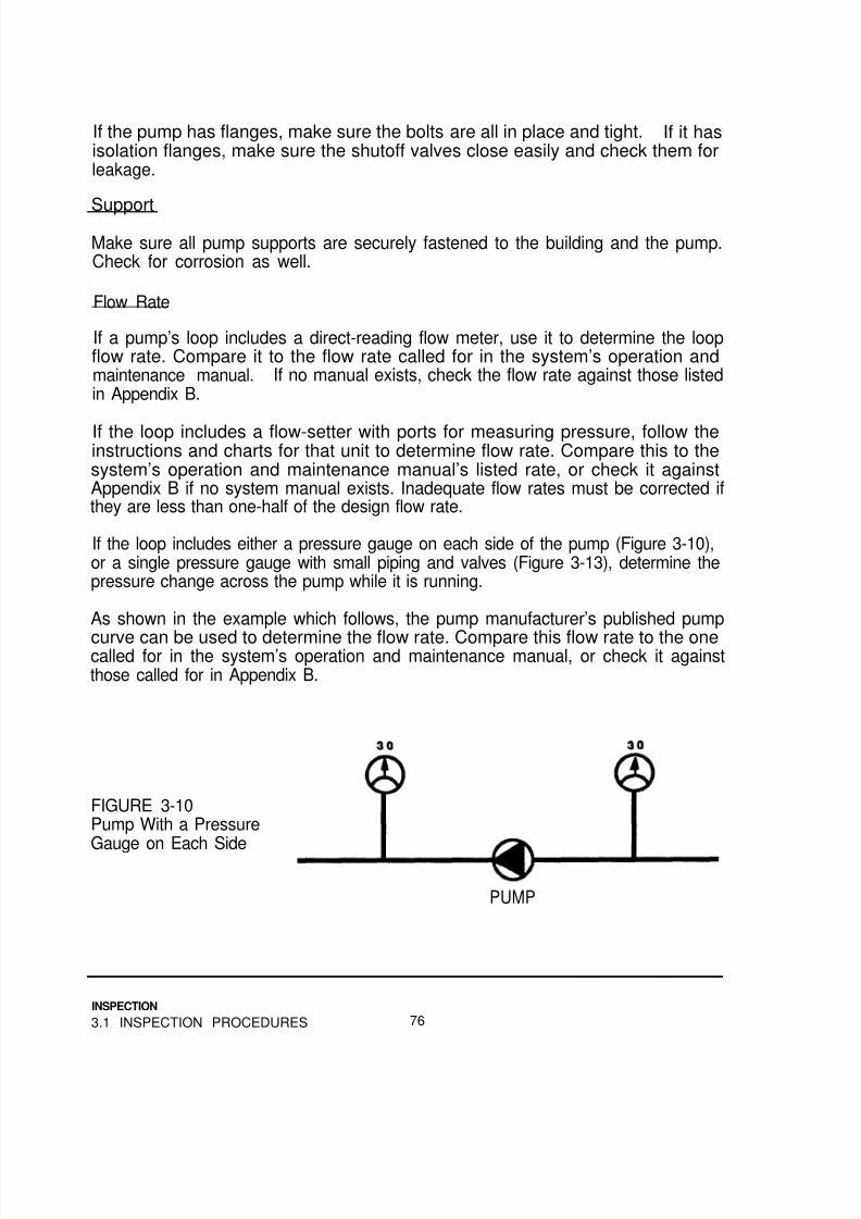
8/14/2019 Navy Maint. & Op of Active Solar Heating Sy
http://slidepdf.com/reader/full/navy-maint-op-of-active-solar-heating-sy 92/277
If the pump has flanges, make sure the bolts are all in place and tight. If it hasisolation flanges, make sure the shutoff valves close easily and check them forleakage.
Support
Make sure all pump supports are securely fastened to the building and the pump.Check for corrosion as well.
Flow Rate
If a pump’s loop includes a direct-reading flow meter, use it to determine the loopflow rate. Compare it to the flow rate called for in the system’s operation andmaintenance manual. If no manual exists, check the flow rate against those listedin Appendix B.
If the loop includes a flow-setter with ports for measuring pressure, follow theinstructions and charts for that unit to determine flow rate. Compare this to thesystem’s operation and maintenance manual’s listed rate, or check it againstAppendix B if no system manual exists. Inadequate flow rates must be corrected ifthey are less than one-half of the design flow rate.
If the loop includes either a pressure gauge on each side of the pump (Figure 3-10),or a single pressure gauge with small piping and valves (Figure 3-13), determine thepressure change across the pump while it is running.
As shown in the example which follows, the pump manufacturer’s published pump
curve can be used to determine the flow rate. Compare this flow rate to the onecalled for in the system’s operation and maintenance manual, or check it againstthose called for in Appendix B.
FIGURE 3-10Pump With a PressureGauge on Each Side
PUMP
INSPECTION
3.1 INSPECTION PROCEDURES 76

8/14/2019 Navy Maint. & Op of Active Solar Heating Sy
http://slidepdf.com/reader/full/navy-maint-op-of-active-solar-heating-sy 93/277
If the two gauges read the same when the pump is off (Figure 3-11), the differentialpressure is simply the outlet pressure minus the inlet pressure. For example, if bothgauges read 30 PSI with the pump off, and when the pump is on the outlet gaugereads 35 and the inlet gauge reads 25, the differential pressure is:
35 PSI - 25 PSI = 10 PSI
FIGURE 3-11
Calibrated GaugesWith the Pump Offand On
However, if the gauges read differently when the system is off (Figure 3-12) andcannot be adjusted to agree, you have to add up both pressure changes. Forexample, at rest, the inlet gauge reads 28 and the outlet gauge reads 30. When thepump is on, the inlet gauge goes to 23, and the outlet gauge goes to 35. The totalof the pressure changes is:
For the inlet gauge: 28 PSI - 23 PSI = 5 PSI
For the outlet gauge: 35 PSI - 30 PSI = 5 PSI
The total pressure change is: 5 PSI + 5 PSI = 10 PSI
77
INSPECTION
3.1 INSPECTION PROCEDURES

8/14/2019 Navy Maint. & Op of Active Solar Heating Sy
http://slidepdf.com/reader/full/navy-maint-op-of-active-solar-heating-sy 94/277

8/14/2019 Navy Maint. & Op of Active Solar Heating Sy
http://slidepdf.com/reader/full/navy-maint-op-of-active-solar-heating-sy 95/277
After determining the pressure change, convert it to feet of water, the usual pressureunit used on pump curves. This is sometimes called feet of head. They are thesame. Multiply the PSI times 2.3 to convert to feet of water. For example, ourexample pump had a pressure change of 10 PSI. This is:
10 PSI x 2.3 = 23 feet of water
The final step is to use the manufacturer’s pump curve to determine what flow ratethe pump will provide working at that pressure change. Using Figure 3-14 as anexample, the 23 feet of pressure change across the pump indicates a flow rate ofabout 30 gallons per minute.
NOTE
While this method is reasonably accurate, it is not perfect. Asthe pump impeller wears, flow rates will decline. If the pumpis moving glycols or oils, there may be a considerable deviationfrom the published pump curve. If the flow rate is 50% higheror lower than the design flow rate, consult the fluid manufacturerfor the correction factor.
FIGURE 3-14A Typical Pump
Curve
The motors of wet rotor pumps never require lubrication. External motor pumpsshould be checked at every inspection. If there is no way to determine lubricantlevels, a regular schedule for adding oil should be established, to avoid over-oilingthe motor.
79
INSPECTION
3.1 INSPECTION PROCEDURES
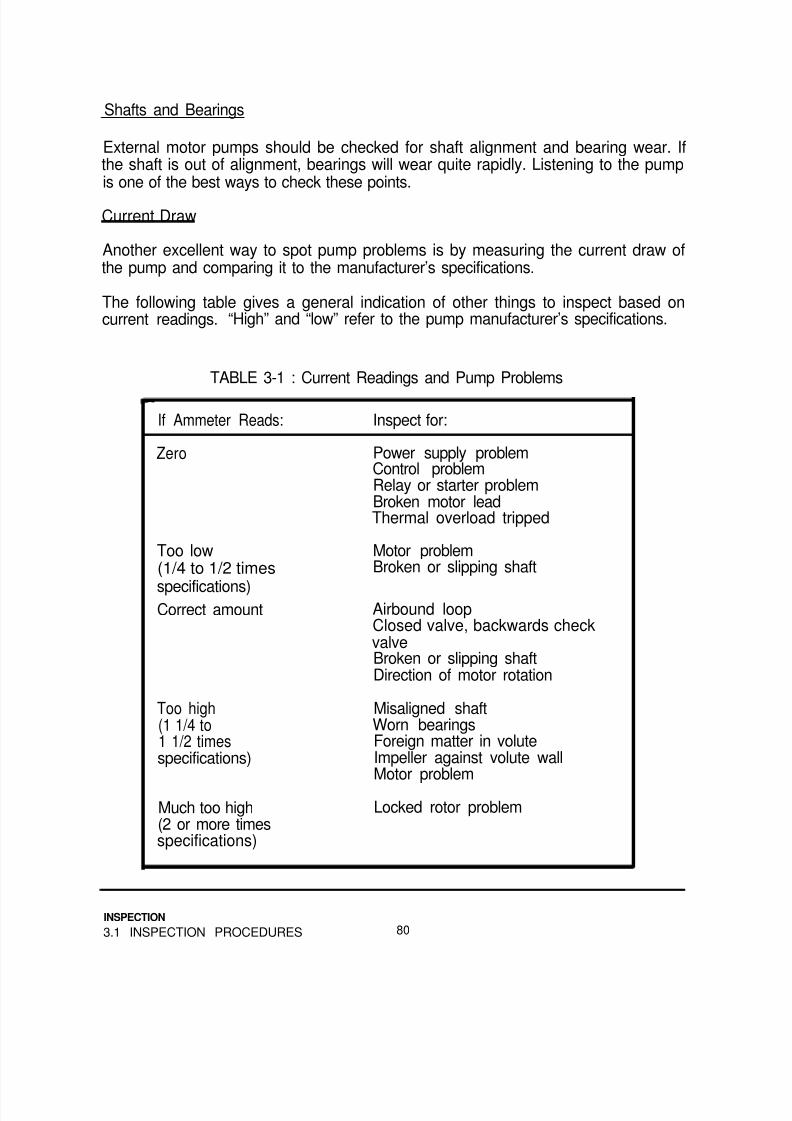
8/14/2019 Navy Maint. & Op of Active Solar Heating Sy
http://slidepdf.com/reader/full/navy-maint-op-of-active-solar-heating-sy 96/277
Shafts and Bearings
External motor pumps should be checked for shaft alignment and bearing wear. Ifthe shaft is out of alignment, bearings will wear quite rapidly. Listening to the pumpis one of the best ways to check these points.
Current Draw
Another excellent way to spot pump problems is by measuring the current draw ofthe pump and comparing it to the manufacturer’s specifications.
The following table gives a general indication of other things to inspect based oncurrent readings. “High” and “low” refer to the pump manufacturer’s specifications.
TABLE 3-1 : Current Readings and Pump Problems
If Ammeter Reads:
Zero
Inspect for:
Power supply problemControl problemRelay or starter problemBroken motor leadThermal overload tripped
Too low(1/4 to 1/2 times
specifications)Correct amount
Motor problemBroken or slipping shaft
Airbound loopClosed valve, backwards checkvalveBroken or slipping shaftDirection of motor rotation
Too high(1 1/4 to1 1/2 timesspecifications)
Misaligned shaftWorn bearingsForeign matter in voluteImpeller against volute wallMotor problem
Much too high(2 or more timesspecifications)
Locked rotor problem
INSPECTION
3.1 INSPECTION PROCEDURES 80

8/14/2019 Navy Maint. & Op of Active Solar Heating Sy
http://slidepdf.com/reader/full/navy-maint-op-of-active-solar-heating-sy 97/277
If the ammeter reads zero, too high or much too high, also check relay contacts fordamage from excessive current draw.
3.1.5 Heat Exchangers.
WARNING!
Always confirm that a double wall heat exchanger is usedwhenever a toxic solar fluid is used, particularly with DHWsystems. This can be determined from the nameplate.
Piping Connections and Seals
Check all heat exchanger ports for signs of leakage or corrosion. Look for loosebolts and leakage at the bonnets of shell and tube heat exchangers.
Supports
Make sure all heat exchanger supports are securely fastened to the building and theheat exchanger. Check for corrosion as well.
Flow Rate
Methods of checking flow rates are described in the preceding section, 3.1.4.Compare it to the specifications in the system’s operation and maintenance manual,or check them against the rules of thumb in Appendix B.
If potable water flow rates are significantly lower than the system specifications,scale may have built up on heat exchanger passages.
It may be worthwhile to have a water hardness test performed, if water quality is notknown. It may also be a good idea to visually inspect the water passages, ifpossible.
Temperature Change
While the system is running, check the temperatures at the inlets and outlets of allheat exchangers. Make sure the temperatures change in the appropriate directions.
INSPECTION
81 3.1 INSPECTION PROCEDURES

8/14/2019 Navy Maint. & Op of Active Solar Heating Sy
http://slidepdf.com/reader/full/navy-maint-op-of-active-solar-heating-sy 98/277

8/14/2019 Navy Maint. & Op of Active Solar Heating Sy
http://slidepdf.com/reader/full/navy-maint-op-of-active-solar-heating-sy 99/277
Usually, water is “softened” to remove scale-causing “hardness.” Typically, this isdone with ion-exchange softening equipment. Test for hardness with any standardwater hardness test equipment.
Sometimes iron creates problems by building up on the inside of piping systems andreducing flow rates, and by giving the water a poor appearance and taste. Standardion-exchange softeners, specialized iron filters or chlorine-based treatments areused to remove iron. These can all be easily checked with a test kit for total iron(both ferrous and ferric iron).
Drainback systems normally use distilled or deionized water.
Glycols
Glycol-based fluids should be checked for glycol concentration and the condition ofthe corrosion inhibitor. If these two cannot be checked, at least check the pH(acidity/alkalinity) of the fluid.
To check glycol concentration, some manufacturers (including Dow ChemicalCompany) furnish simple test kits with simple test strips and color charts(Figure 3-1 5). Another method is an optical refractometer (Figure 3-1 6). Both thesemethods require only a few drops of fluid and are quite simple.
To check the condition of the corrosion inhibitor, measure either the pH or thereserve alkalinity of the fluid. Most glycol manufacturers recommend that the pHshould not drop below 6.0 and the reserve alkalinity should not drop below 8.0.Should either condition be too low, the fluid must be replaced or reinhibited.
To check the pH, use pH paper or tape, or have a laboratory analyze the fluid. If
using pH tape, use fairly fresh tape with a pH range from 6.0 to 8.0. Watertreatment specialists or swimming pool chemical suppliers are good sources forpHtape.
To check the reserve alkalinity, use a special test strip from the manufacturer, orhave a lab check it. Some glycol manufacturers offer free testing for systems usinglarge amounts of fluid (over 50 to 200 gallons).
The, color of most glycol-based solar fluids is not usually a good indicator of fluid
condition. However, if the fluid appears and smells “burnt,” or has visible sludge, itshould be replaced after the system is flushed out.
83
INSPECTION
3.1 INSPECTION PROCEDURES

8/14/2019 Navy Maint. & Op of Active Solar Heating Sy
http://slidepdf.com/reader/full/navy-maint-op-of-active-solar-heating-sy 100/277
FIGURE 3-15Dowfrost Test Kit
FIGURE 3-16OpticalRefractometer
INSPECTION
3.1 INSPECTION PROCEDURES 84

8/14/2019 Navy Maint. & Op of Active Solar Heating Sy
http://slidepdf.com/reader/full/navy-maint-op-of-active-solar-heating-sy 101/277
Synthetic and Silicone Oils
Oils do not require replacement or reinhibiting. However, the fluid pressure must beadequate.
Check for the recommended pressure from section 5.2.6 of this manual.
3.1.7 Controls,
Electrical Connections
Check all conduit and wiring connections. Make sure the system is mechanicallygrounded (to earth). Pay particular attention to the sensor wire connections. Makesure no small strands of wire from adjacent terminals touch each other. Suchcontact provides a direct short circuit which completely disrupts normal controloperation.
Mounting
Be sure the control and associated conduit is securely mounted.
Controls: Jumper Method
With all sensor wires disconnected and the control switch in the “automatic” position, jumper the two terminals marked “Collector” (or “COLL,” etc.) (Figure 3-17a). Thesolar loop pump (and water loop pump, if used) should come on.
FIGURE 3-17Checking On/OffOperation by theJumper Method
85
INSPECTION
3.1 INSPECTION PROCEDURES

8/14/2019 Navy Maint. & Op of Active Solar Heating Sy
http://slidepdf.com/reader/full/navy-maint-op-of-active-solar-heating-sy 102/277
With the collector sensor terminals shorted, jumper the storage sensor terminalsmarked “Storage” (or “STOR,” etc.) (Figure 3-17b). The pump(s) should go off.
To test the high limit function, first determine the brand and type of differentialthermostat controlling the system. Most controls are 10K, that is their sensors have
10,000 ohms resistance at 77°F. If you have any doubt about this, refer to thesystem’s operation and maintenance manual. If one does not exist, remove asensor, give it time to come to room temperature and measure its resistance with anohmmeter.
Controls manufactured by Controlex (Natural Power), Johnson Controls, BarberColeman, Honeywell, Robertshaw and others are not 10K differential thermostats.These controls use RTD sensors instead of thermistors. Consult the manufacturerfor further information.
Heliotrope General controls may use 10K or 3K sensors. Table 3-2 contains
additional information on these controls.
Determine the high limit setting of the control from Table 3-2, the control labeling orthe setting of the control’s high limit adjustment dial. This dial is usually on apotentiometer, sometimes called a “pot.” (Figure 3-18)
FIGURE 3-18High Limit Dial (left) andControl Switch (right) on aSolar Control
INSPECTION
3.1 INSPECTION PROCEDURES 86

8/14/2019 Navy Maint. & Op of Active Solar Heating Sy
http://slidepdf.com/reader/full/navy-maint-op-of-active-solar-heating-sy 103/277
Jumper the collector sensor terminals on the control. Once the system is running,hold the leads of an appropriate resistor against the storage sensor terminals(Figure 3-19). The system should turn off, as the control is being told the storagetank is above the high temperature.
FIGURE 3-19Checking High Limit
Function With a SingleResistor
TABLE 3-2: Characteristics of Available Controls (As of January, 1988)
Manufacturer: Model: Type: On/Off: (ºF) High Limit: (ºF)
HeliotropeGeneral*
Independent
Energy
PyramidControls
TempTrak II SeriesDTT-64 SeriesDTT-84/94 Series
DTT-64DDDTT-74 Series
CM30/32CM-33CM-50
C-30 SeriesC-35 Series
All
3K/10K Adj: 50-10020/3 or 10/3
10K 18/5 or 9/4
10K
30/310K 20/5 or 10/5
10K Adj: 8-24/410K Adj: 8-24/410K Adj: 15/4 to
40/2010K 20/5 or 8/310K 4/1 or 8/3
10K 14/3
Adj: 80-215None, 160, or 180160 or 180
180None, 160, or 180
Adj: 110-230Adj: 50-104Adj: 60-160
Adj: 105-212Adj: 62-104
163
Rho Sigma RS504 Series 10K 20/3 or 12/3** 160RS121 Series 10K 20/3 Adj: 120-220RS360 Series 10K 20/3.5 Per specification
* Older Heliotrope General Controls are all 3K** Proportional control: The pump motor is run at a speed proportional to the
differential. This type of control is rarely used.
87
INSPECTION
3.1 INSPECTION PROCEDURES

8/14/2019 Navy Maint. & Op of Active Solar Heating Sy
http://slidepdf.com/reader/full/navy-maint-op-of-active-solar-heating-sy 104/277
Use Table 3-3 or 3-4 to determine the right resistance to use to simulate a particulartemperature. An abbreviated version, with resistor color codes, is presented inTable 4-3.
Controls. Tester Method.
A more accurate method of testing differential thermostats is with a special testerdesigned for the purpose. Normally, these units have four leads or terminals.These are connected to the collector and storage sensor terminals of the control.The tester supplies a calibrated resistance to the two sensor inputs to simulatechanging sensor temperatures. (Figure 3-20)
Most of the available testers supply a fixed resistance to the storage terminals andchange the resistance supplied to the collector terminals. The numbers on thetester dial usually refer to the temperature difference between the storage andcollector terminals.
As the tester dial is slowly turned to greater temperature differential settings, theresistance supplied to the collector sensor terminals is lowered. At the “on”differential, the control should turn on.
FIGURE 3-20Solar ControlTester
INSPECTION
3.1 INSPECTION PROCEDURES 88

8/14/2019 Navy Maint. & Op of Active Solar Heating Sy
http://slidepdf.com/reader/full/navy-maint-op-of-active-solar-heating-sy 105/277
Next, turn the dial slowly downward to lower temperature differential settings. Thisincreases the resistance shown to the collector sensor terminal, and at the “off”differential, the control should shut off.
Many testers also include a high limit test function. Generally, the tester shorts outthe collector sensor’s terminals, to ensure the control is trying to run the system.Then, the resistance supplied to the storage sensor terminals is reduced, simulatinga rising storage temperature. When the high limit is reached, the control shouldshut off.
The dials on most testers are not very accurate. If the control has a digital display,use that instead of the numbers on the tester dial. In descending order of accuracy,the dials and readouts encountered during control and sensor testing are:
Most accurate:
Least accurate:
Control digital displayDigital ohmmeter
Analog ohmmeterResistor color codeControl tester dialControl adjustment pot dials
Sensors: For Controls Without Digital Displays
To check suspicious sensors, disconnect the wires from their terminals at thecontrol. With all sensors removed, the control should be off when it is in the “auto”position. Leave the connections intact at the sensor for the time being. Using anohmmeter and the appropriate temperature vs. resistance chart (Table 3-3 or 3-4),
determine if the resistance of the sensor is appropriate for the temperature it shouldbe measuring. If using an analog meter with several resistance scales, the 100 x Rscale is normally the most useful.
Confirm also that the sensor resistance changes as the sensor temperaturechanges. This may require warming a cool sensor in your hand, or moving a sensoroff a warm collector or tank into the cooler air.
CAUTION
Do not immerse sensors in warm or cold water. Most sensorsare not waterproof and can be damaged with water. Resistancereadings of an immersed sensor will not be correct. Iftemperature extremes are needed to check the sensor, wrap itin a plastic bag before immersing it in water.
89
INSPECTION
3.1 INSPECTION PROCEDURES

8/14/2019 Navy Maint. & Op of Active Solar Heating Sy
http://slidepdf.com/reader/full/navy-maint-op-of-active-solar-heating-sy 106/277
Remember, most sensor’s resistance goes up as temperature goes down. Atemperature increase results in a resistance decrease. If the ohmmeter shows adirect short (zero ohms), or an open circuit (infinite ohms), check the sensor wiringas well as the sensor itself.
Check sensor wiring for staples shorting out the wires, loose or corrodedconnections and outright breaks.
Make sure sensor wiring is located away from line voltage wiring and motors.Maintain at least 1 foot from 120V wiring and at least 2 feet from 240V. It is veryeasy for a small electrical current to be induced in the low voltage sensor wires.This current will make normal control operation impossible.
Sensors: For Controls With Digital Displays
If the control has a digital display, leave the sensor wires connected and use thecontrol display to check the sensors. If the displayed temperatures do not appearappropriate, disconnect the sensor wires from the control and use an ohmmeter tocheck the sensor.
Many digital displays indicate short or open circuits by flashing the digits on display.Again, an ohmmeter should be used on disconnected sensor wires.
NOTE
Whenever checking controls or sensors, also check to be sure thecollector with the sensor is properly grounded.
Freeze Snap Switches
In some systems, one or more freeze snap switches are installed in series orparallel with the collector sensor. In others, they are part of a separate circuit.Redundant sensors in different locations provide added protection against freezing.
Multiple freeze sensors are sometimes used in parallel or series to provideredundant protection for collectors and exposed piping. Make sure they are in goodthermal contact with the piping or collector components, and that they are wired
correctly in series or parallel.
Be sure the freeze snap switches used with a control are made or recommended bythe control manufacturer. Some switches open on a temperature drop, and othersclose on a temperature drop. The use of the wrong snap switch can destroy thecollectors by allowing them to freeze.
INSPECTION
3.1 INSPECTION PROCEDURES 90

8/14/2019 Navy Maint. & Op of Active Solar Heating Sy
http://slidepdf.com/reader/full/navy-maint-op-of-active-solar-heating-sy 107/277
TABLE 3-3: Temperature vs. Resistance in Ohms for 10K Sensors
ºF ºC Resistance ºF ºC Resistance ºF ºC Resistance
32343638404244
46485052545658
606264
66
6870
7274
76
788082
84
86889092949698
100102104
0.0
1.12.2
3.34.45.66.77.88.910.011.112.213.314.4
15.616.717.818.920.021.122.223.3
24.4
25.626.727.828.9
30.031.132.233.3
34.435.636.737.838.940.0
32,654
30,85929,17427,59226,10524,70923,39522,16020,99819,90318,87317,90316,98816,126
15,31314,54613,82213,13912,49311,88311,30710,76210,2479,7609,2988,8628,448
8.0567,6657,3336,9996,6836,3826,0975,8275,5705,326
106 41.1 5,093
108 42.2 4,873110 43.3 4,663112 44.4 4,464114 45.6 4,274116 46.7 4,093118 47.8 3,921120 48.9 3,758122 50.0 3,602124 51.1 3,453126 52.2 3,312128 53.3 3,177130 54.4 3,048132 55.6 2,925
134 56.7 2,808136 57.8 2,697138 58.9 2,590140 60.0 2,488142 61.1 2,391144 62.2 2,298146 63.3 2,209148 64.4 2,124150 65.6 2,043152 66.7 1,966154 67.8 1,891156 68.9 1,820158 70.0 1,753
160 71.1 1,688162 72.2 1,625164 73.3 1,566166 74.4 1,509168 75.6 1,454170 76.7 1,402172 77.8 1,351174 78.9 1,303176 80.0 1,257178 81.1 1,213
180
182184186188190192194196198200202204206
208210212214216218220222224226228230232
234236238240242244246248250
82.2 1,170
83.3 1,12984.4 1,09085.6 1,05386.7 1,01787.8 98288.9 949
91.190.0 917
92.2886857
94.493.3 828
95.6801775
96.7 749
97.8 72598.9 702100.0 679101.1 658102.2 637103.3 617104.4 597105.6 579106.7 561107.8 543108.9 527110.0 511111.1 495
112.2 480113.3 466114.4 452115.6 438116.7 425117.8 413118.9 401120.0 389121.1 378
91
INSPECTION
3.1 INSPECTION PROCEDURES

8/14/2019 Navy Maint. & Op of Active Solar Heating Sy
http://slidepdf.com/reader/full/navy-maint-op-of-active-solar-heating-sy 108/277
TABLE 3-4: Temperature vs. Resistance in Ohms for 3K Sensors
ºF ºC Resistance ºF ºC Resistance ºF ºC Resistance
32.0 0 9,810 105.8 41 1,540 179.6 82 354
33.8 1 9,300 107.8 42 1,480 181.4 83 34235.6 2 8,850 109.4 43 1,420 183.2 84 33337.4 339.2 4 8,010
8,430 111.2 44 1,360 185.0 85 321
41.0 5 7,620113.0 45 1,310 186.8 86 312114.8 46 1,260 188.6 87 303
42.8 6 7,260 116.6 47 1,210 190.4 88 29344.6 7 6,900 118.4 48 1,170 192.2 89 28446.4 8 6,570 120.2 49 1,120 194.0 90 27548.2 9 6,270 122.0 50 1,080 195.8 91 267
51.853.6
1150.0 10 5,970
5,700123.8125.6
5152
1,0401,002
197.6199.4
9392
259251
12 5,430 127.4 53 966 201.2 94 24355.4 13 5,190 129.2 54 930 203.0 95 236
57.2 14 4,950 131.0 55 879 204.8 96 22959.0 15 4,710 132.8 56 206.6 97 22360.8 16 4,500 134.6 57 831
864208.4 98 215
62.664.466.2
1718
4,2904,110
136.4138.2
5859
774801
212.0210.2
99100
210204
19 3,930 140.0 60 747 213.8 101 19868.0 20 3,750 141.8 61 720 215.6 102 19269.8 21 3,570 143.6 62 696 217.4 103 18771.6 22 3,420 145.4 63 672 219.2 104 18273.4 23 3,270 147.2 64 648 221.0 105 17675.2 24 3,150 149.0 65 624 222.8 106 17177.0 25 3,000 150.8 66 603 224.6 107 16778.8 26 2,870 152.6 67 582 226.4 108 162
80.6 27 2,750 154.4 68 564 228.2 109 15882.4 28 2,630 156.2 69 543 230.0 110 15384.2 29 2,520 158.0 70 525 231.8 111 14986.0 .30 2,420 159.8 71 507 233.6 112 14587.8 31 2,320 161.6 72 492 235.4 113 141
89.6 32 2,220 163.4 73 474 237.2 114 13791.4 33 2,130 165.2 74 459 239.0 115 13493.2 34 2,040 167.0 75 444 240.8 116 13095.0 35 1,960 168.8 76 429 242.6 117 12796.8 36 1,880 170.6 77 417 244.4 118 12398.6 37 1,800 172.4 78 402 246.2 119 120
100.4 38 1,730 174.2 79102.2 39 1,670 176.0 80 378
390 248.0 120 117249.8 121 114
104.0 40 1,600 177.881
366
INSPECTION
3.1 INSPECTION PROCEDURES 92
8/14/2019 Navy Maint. & Op of Active Solar Heating Sy
http://slidepdf.com/reader/full/navy-maint-op-of-active-solar-heating-sy 109/277
3.1.8 Storage Tanks.
Drain Valves
Check that the drain valve on the storage tank opens and closes properly withoutleaking. Look for leaks at the piping connection between the valve and the tank.
Insulation
Tank insulation must be complete, dry and properly jacketed. If foam insulation hasbeen applied to the exterior, make sure it is still in good condition.
If the tank is buried, take tank-top temperature readings one hour after the end of asolar collection day and again the next morning. During that night, bypass the tank,so any temperature loss is through the tank wall and insulation, not to a load. Theovernight loss of heat on a properly insulated tank will typically result in a
temperature loss of less than ten degrees Fahrenheit.
Sacrificial Anode
Unscrew and inspect the sacrificial anode in steel tanks with glass linings. The pipedope used by the manufacturer makes the rod difficult to remove the first time. Afterinspection, clean this dope off the threads and use teflon tape. This will makesubsequent inspections easier. Attach a note to the tank indicating condition of theanode and the date of the last replacement, if known.
Replacement of depleted anode rods is critical to the lifetime of a storage tank.
Fittings and Piping
Check all fittings for leaks and evidence of corrosion. Insulation on piping must becomplete. Insulation jacketing, if used, must be intact.
Sensor and Sensor Wiring
The previous section contains information on checking the sensor on the tank.Make sure the sensor wiring is protected from physical damage and is kept at least1 foot away from 120V wiring and at least 2 feet away from 240V wiring.
Heating Element
If the tank has a back-up electric element, be sure the sensor and back-up elementwiring are separated by at least one foot.
93
INSPECTlON
3.1 INSPECTION PROCEDURES

8/14/2019 Navy Maint. & Op of Active Solar Heating Sy
http://slidepdf.com/reader/full/navy-maint-op-of-active-solar-heating-sy 110/277
The element must be in the upper half of the solar tank. An auxiliary heat source inthe bottom of the tank would interfere with the system’s ability to store solar heat.
3.2 SAMPLE INSPECTION CHECKLIST
An inspection checklist is shown on the next four pages. It can be copied and useddirectly, or it can be retyped with modifications for particular systems.
This version has two columns. If no repairs are required, place a check in the “OK”column. If repairs are needed, check the “Repair” column. Use the “RecommendedActions” section near the end for notes on necessary repairs.
After the checklist is filled out, use it to pinpoint necessary maintenance or repairs.Then file it with all the other system inspection sheets, or with the operation andmaintenance manual for that system.
INSPECTION
3.2 SAMPLE INSPECTION CHECKLIST 94
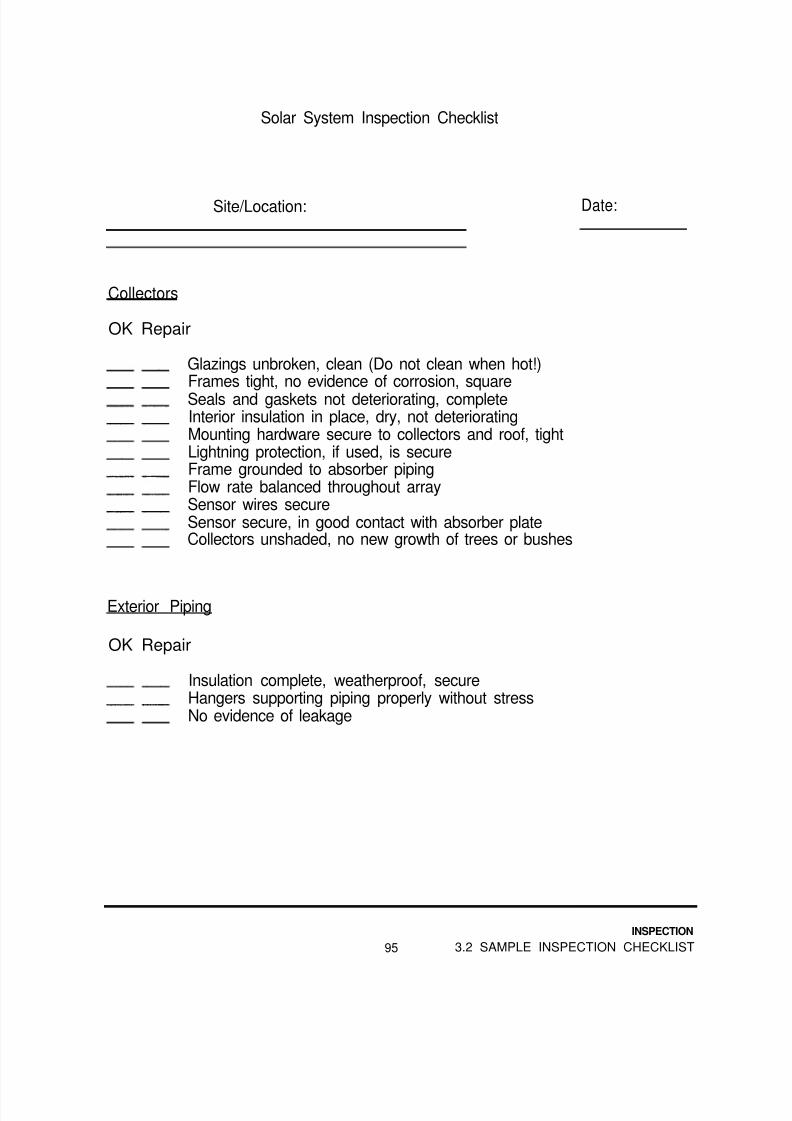
8/14/2019 Navy Maint. & Op of Active Solar Heating Sy
http://slidepdf.com/reader/full/navy-maint-op-of-active-solar-heating-sy 111/277
Solar System Inspection Checklist
Site/Location: Date:
Collectors
OK Repair
Glazings unbroken, clean (Do not clean when hot!)Frames tight, no evidence of corrosion, squareSeals and gaskets not deteriorating, completeInterior insulation in place, dry, not deterioratingMounting hardware secure to collectors and roof, tightLightning protection, if used, is secureFrame grounded to absorber pipingFlow rate balanced throughout arraySensor wires secureSensor secure, in good contact with absorber plateCollectors unshaded, no new growth of trees or bushes
Exterior Piping
OK Repair
Insulation complete, weatherproof, secureHangers supporting piping properly without stressNo evidence of leakage
95
INSPECTION
3.2 SAMPLE INSPECTION CHECKLIST

8/14/2019 Navy Maint. & Op of Active Solar Heating Sy
http://slidepdf.com/reader/full/navy-maint-op-of-active-solar-heating-sy 112/277
Interior Piping
OK Repair
Insulation complete, secureNo evidence of leakageValves in correct positions*Hangers supporting piping properly without stress
Pumps
OK Repair
Electrical connections secure
Piping connections secure, no evidence of corrosionPump properly supportedFlow rate in appropriate range*Adequate lubrication supplied (dry rotor pumps only)Current draw is appropriate*
OK Repair
Heat Exchanger
No evidence of corrosion at fittings (check bonnet)Piping connections secureAnode in water manifold presentTemperature differences appropriate*Water level in drainback tank, if used, correct*
* Check the system’s operation and maintenance manual, or thismanual’s appendices for more information.
INSPECTION
3.2 SAMPLE INSPECTION CHECKLIST 96
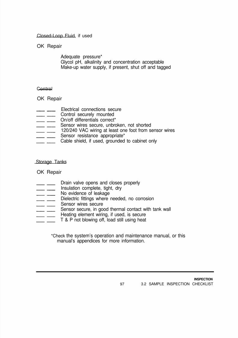
8/14/2019 Navy Maint. & Op of Active Solar Heating Sy
http://slidepdf.com/reader/full/navy-maint-op-of-active-solar-heating-sy 113/277
Closed-Loop Fluid, if used
OK Repair
Adequate pressure*Glycol pH, alkalinity and concentration acceptableMake-up water supply, if present, shut off and tagged
Control
OK Repair
Electrical connections secureControl securely mounted
On/off differentials correct*Sensor wires secure, unbroken, not shorted120/240 VAC wiring at least one foot from sensor wiresSensor resistance appropriate*Cable shield, if used, grounded to cabinet only
Storage Tanks
OK Repair
Drain valve opens and closes properlyInsulation complete, tight, dryNo evidence of leakageDielectric fittings where needed, no corrosionSensor wires secureSensor secure, in good thermal contact with tank wallHeating element wiring, if used, is secureT & P not blowing off, load still using heat
*Check the system’s operation and maintenance manual, or thismanual’s appendices for more information.
97
INSPECTION
3.2 SAMPLE INSPECTION CHECKLIST

8/14/2019 Navy Maint. & Op of Active Solar Heating Sy
http://slidepdf.com/reader/full/navy-maint-op-of-active-solar-heating-sy 114/277
Paperwork
OK Repair
Operation and maintenance manual for system on site or available
Flow diagram and sequence of operation on site or availableService record for system on site or availablePhotographs taken and placed in service recordThis inspection record filed in service record
Recommended Actions. if any;
Notes:
Inspected by:
Approved by:
INSPECTION
3.2 SAMPLE INSPECTION CHECKLIST 98

8/14/2019 Navy Maint. & Op of Active Solar Heating Sy
http://slidepdf.com/reader/full/navy-maint-op-of-active-solar-heating-sy 115/277
3.3 SIMPLIFIED INSPECTION PROCEDURES FOR SMALL SYSTEMS
When many small systems are to be inspected, such as domestic hot water systemson military family housing units, a simpler inspection procedure can be used toreduce the inspection time per system.
These inspection procedures are less detailed and cover fewer items, but areadequate to turn up most service needs. It is important to complete all theinspection tasks for all the systems, and to remain alert for defects which are notspecifically listed.
Notice that the last section of the checklist can be performed at another time, wheninspection personnel are on top of the building to inspect roofs.
99
INSPECTION
3.3 INSPECTION OF SMALL SYSTEMS

8/14/2019 Navy Maint. & Op of Active Solar Heating Sy
http://slidepdf.com/reader/full/navy-maint-op-of-active-solar-heating-sy 116/277
DHW System Inspection Checklist
Site/Location: Date:
Collectors (Inspect from the ground)
OK Repair
Glazings unbroken, without condensation or outgassingPiping insulation complete, jacket in acceptable conditionNo evidence of fluid leakage
Piping hanging or supported properly
Interior Piping
OK RepairPiping insulation complete, jacket in acceptable conditionNo evidence of fluid leakagePiping hanging or supported properlyValves all in correct positions*When pump is running, pump sounds appropriate
No gurgling noises in piping, except for filling anddraining draindown and drainback collector loopsPressure of closed loops appropriate*Pressure relief valve on closed loop installed and discharge
properly pipedGlycol concentration, pH and alkalinity acceptable
* Check the system’s operation and maintenance manual, or this manual’sappendices for more information.
INSPECTION
3.3 INSPECTION OF SMALL SYSTEMS 100
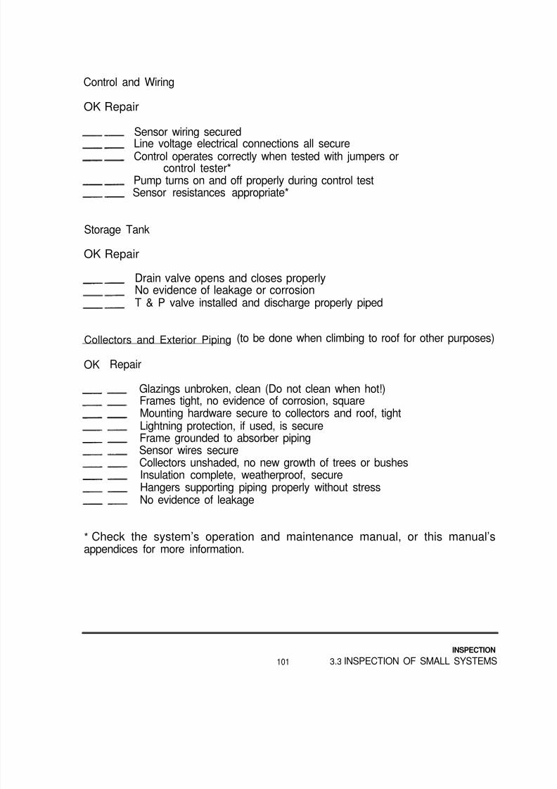
8/14/2019 Navy Maint. & Op of Active Solar Heating Sy
http://slidepdf.com/reader/full/navy-maint-op-of-active-solar-heating-sy 117/277
Control and Wiring
OK Repair
Sensor wiring securedLine voltage electrical connections all secureControl operates correctly when tested with jumpers or
control tester*Pump turns on and off properly during control testSensor resistances appropriate*
Storage Tank
OK Repair
Drain valve opens and closes properlyNo evidence of leakage or corrosionT & P valve installed and discharge properly piped
Collectors and Exterior Piping (to be done when climbing to roof for other purposes)
OK Repair
Glazings unbroken, clean (Do not clean when hot!)Frames tight, no evidence of corrosion, square
Mounting hardware secure to collectors and roof, tightLightning protection, if used, is secureFrame grounded to absorber pipingSensor wires secureCollectors unshaded, no new growth of trees or bushesInsulation complete, weatherproof, secureHangers supporting piping properly without stressNo evidence of leakage
* Check the system’s operation and maintenance manual, or this manual’s
appendices for more information.
101
INSPECTION
3.3 INSPECTION OF SMALL SYSTEMS
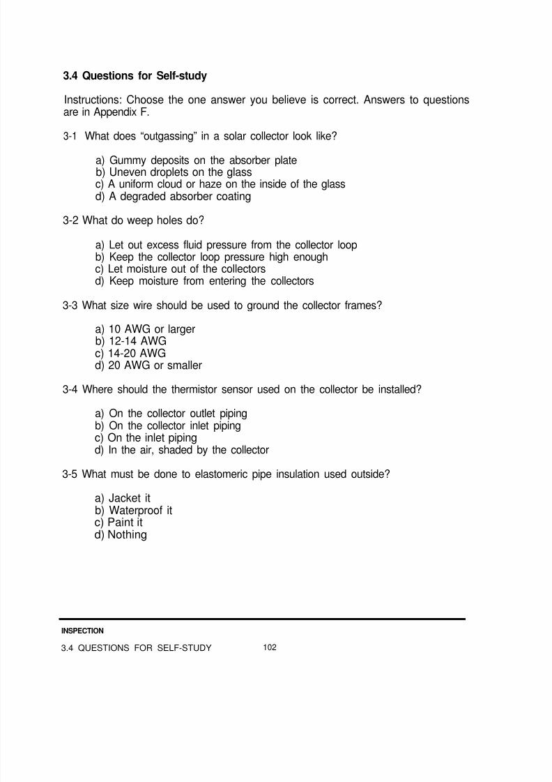
8/14/2019 Navy Maint. & Op of Active Solar Heating Sy
http://slidepdf.com/reader/full/navy-maint-op-of-active-solar-heating-sy 118/277
3.4 Questions for Self-study
Instructions: Choose the one answer you believe is correct. Answers to questionsare in Appendix F.
3-1 What does “outgassing” in a solar collector look like?
a) Gummy deposits on the absorber plateb) Uneven droplets on the glassc) A uniform cloud or haze on the inside of the glassd) A degraded absorber coating
3-2 What do weep holes do?
a) Let out excess fluid pressure from the collector loopb) Keep the collector loop pressure high enough
c) Let moisture out of the collectorsd) Keep moisture from entering the collectors
3-3 What size wire should be used to ground the collector frames?
a) 10 AWG or largerb) 12-14 AWGc) 14-20 AWGd) 20 AWG or smaller
3-4 Where should the thermistor sensor used on the collector be installed?
a) On the collector outlet pipingb) On the collector inlet pipingc) On the inlet pipingd) In the air, shaded by the collector
3-5 What must be done to elastomeric pipe insulation used outside?
a) Jacket itb) Waterproof itc) Paint itd) Nothing
INSPECTION
3.4 QUESTIONS FOR SELF-STUDY 102
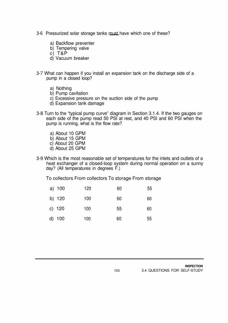
8/14/2019 Navy Maint. & Op of Active Solar Heating Sy
http://slidepdf.com/reader/full/navy-maint-op-of-active-solar-heating-sy 119/277

8/14/2019 Navy Maint. & Op of Active Solar Heating Sy
http://slidepdf.com/reader/full/navy-maint-op-of-active-solar-heating-sy 120/277
3-10 At a minimum, what should glycol-based solar fluids be checked for?
a) PHb) Pressurec) Dissolved copper
d) Dissolved oxygen
3-11 At a minimum, what should oil-based solar fluids be checked for?
a) PHb) Pressurec) Dissolved copperd) Dissolved oxygen
3-12 With all sensor wires disconnected, the switch in the “auto” position, and a jumper across the collector sensor terminals, what should a functionaldifferential thermostat do?
a) Stop running the pumpb) Run the pump for a few minutes, then stopc) Run the pumpd) Nothing
3-13 A 10K thermistor sensor has a measured resistance of 5000 ohms. What isthe sensors approximate temperature in degrees F?
a) 57b) 77c) 107d) 212
3-14 A 3K thermistor sensor has a measured resistance of 5000 ohms. What is thesensor’s approximate temperature in degrees F?
a) 57b) 77c) 107d) 212
3-15 The temperature of the solar fluid leaving the heat exchanger for the collector
should be:
a) Lower than temperature of the fluid enteringb) Equal to the temperature of the fluid enteringc) Higher than the temperature of the fluid enteringd) The same as the air temperature around the collector
INSPECTION
3.4 QUESTIONS FOR SELF-STUDY 104
8/14/2019 Navy Maint. & Op of Active Solar Heating Sy
http://slidepdf.com/reader/full/navy-maint-op-of-active-solar-heating-sy 121/277
4.0TROUBLESHOOTING
What You Will Find in This Chapter
This chapter contains information on determining what is wrong with a solar system.A troubleshooting chart is provided.
Information on how to repair the problems that troubleshooting turns up can befound in Chapter 5, Repair. Preventive maintenance is covered in Chapter 6
The first section of this chapter describes troubleshooting techniques. Thoseunfamiliar with troubleshooting should read this information carefully.
The information in Appendices A, B and C will be helpful in performing theoperations described in this chapter.
4.1 TROUBLESHOOTING TECHNIQUES
Troubleshooting an HVAC system should involve more than looking for an obviousproblem, or replacing components at random in an attempt to get the systemworking again. This is particularly true of solar heating systems. What is required isa systematic procedure that carefully “troubleshoots” the system until the problem islocated and repaired.
Cause or Symptom
What may appear to be the cause of a problem may actually be a symptom ofanother problem. For example, if a sensor is secured to an ungrounded solarcollector, a discharge of static electricity may travel through the sensor wire and ruinthe control.
Replacing the control does not solve the problem that destroyed it. The new controlis still likely to be damaged, and the system will be inoperative again. If the collector
with the sensor is properly grounded, the actual problem has been solved. Now anew control can be expected to remain functional.
TROUBLESHOOTING
105 4.1 TROUBLESHOOTING TECHNIQUES

8/14/2019 Navy Maint. & Op of Active Solar Heating Sy
http://slidepdf.com/reader/full/navy-maint-op-of-active-solar-heating-sy 122/277
"Low Impact" Troubleshooting
Another peculiarity of solar systems is the difficulty of performing sometroubleshooting procedures without making it a major undertaking.
As an example, it is difficult to examine the interior of the collector loop pump of aclosed-loop system. The process may require completely draining the solar fluidinto buckets or drums, disassembling and reassembling the pump and refilling thesystem loop with fluid.
On the other hand, checking the electrical current draw of the pump can confirm ordeny that the pump rotor is locked. This can be done without ever opening up thecollector loop. This “low impact” troubleshooting usually saves time, material andmoney.
Less Likely. But Easy
Most “low impact” troubleshooting is relatively quick and easy. For this reason, itmay make sense to do them, even if they relate to causes you believe are unlikely.Occasionally, the cause of a problem is not one of the likely ones, and a fewminutes spent performing easy operations is well-rewarded. Also, following asystematic troubleshooting procedure will uncover other problems that should berepaired for long term performance and trouble free maintenance.
Multiple Problems
Never assume that a system is completely without faults after correcting a problem.
A few more minutes spent checking out the rest of the system may save a trip backlater to “rerepair” the system.
Five Steps of Good Troubleshooting
Good troubleshooters usually follow some variation of the following steps whenworking:
o Planningo F ind ing the causeo Repairing
o Testingo Keeping records
TROUBLESHOOTING
4.1 TROUBLESHOOTING TECHNIQUES 106

8/14/2019 Navy Maint. & Op of Active Solar Heating Sy
http://slidepdf.com/reader/full/navy-maint-op-of-active-solar-heating-sy 123/277
Planning begins with thinking about the possible causes of a problem before goingto the site. This includes the tools andmaterials necessary to determine what iscausing the problem, and estimating the time required to find and correct it. Fridayafternoon at 4:00 is a bad time to start tearing down a DHW system, particularly ifyou may require parts which take 30 days to come in.
Finding the cause is the investigation phase. Start with low impact checks, proceedin an organized and logical fashion, and at tempt to isolate the results of testing tothe component being tested.
Sometimes the only way to determine if a component is working properly or not is toreplace it and see what happens. Remember that this may fix the symptom but itcan fail to turn up the real cause of a problem.
Repairs can be made on a “band-aid” basis, doing as little as possible to get thesystem running again. Another approach is to replace major portions of the system
to be absolutely certain the problem is gone. The correct approach is to determinewhat the real cause of a problem is, and make repairs that solve that problem so itdoes not happen again.
Whether to repair or replace defective components depends on the cost andavailability of the component. Generally, the more expensive and difficult it is toobtain something, the more appropriate the repair of the component. If the part ischeap and readily available, it generally will be replaced. If repairs can be made tothe defective component, it can become the new replacement the next time thissame component fails in this or other systems.
After the cause of a problem has been identified and corrected, inspect and test theentire system. This confirms that the new components are working, and that no
other problems exist.
The defective components should be tested as well. The best time is usually beforerebuilding. As an example, if a control works fine on a test bench, but not at all atthe site, a problem exists at the site that will not let the new control work thereeither.
If the part is truly defective, look for the reason it failed. For example, did the controlget wet? Will the new control also get wet and fail?
The last part of troubleshooting is record-keeping. Maintenance and repair recordsare kept to maintain a history of each system. Troubleshooting records should bepart of that written history. In addition, writing down the troubleshooting processpreserves that information for the person who found the problem.
TROUBLESHOOTING
107 4.1 TROUBLESHOOTING TECHNIQUES

8/14/2019 Navy Maint. & Op of Active Solar Heating Sy
http://slidepdf.com/reader/full/navy-maint-op-of-active-solar-heating-sy 124/277
The sample repairs worksheet at the end of Chanter 5, Repairs, includes a sectionto describe what troubleshooting was done on a particular system. We suggest youuse it, or one like it.
4.2 TROUBLESHOOTING CHART
How to Use This Chart;
The troubleshooting chart is arranged in sections which correspond to typicalproblems encountered with solar heating systems. Any of these problems may befound through a scheduled inspection, or by the system users.
Each problem section includes symptoms, followed by possible causes for eachsymptom. Causes are arranged with the most likely ones listed first.
Again, check the “low impact” source of a problem first, and remember more thanone problem source may exist to find and fix. Careful testing and inspecting mayavoid another trip back to “rerepair" the system.
The next section contains information on specific troubleshooting operations, andtips on common causes.
Information on recommended repair actions can be found in Chapter 5 in the repairand replacement section devoted to each component. (For example, sensor andcontrol repair and replacement procedures are in Section 5.1.7.)
PROBLEM
Tank temperaturelower than normal
SYMPTOM CAUSE
Collector loop shows Collector loop airboundloss of pressure
Leak in absorber plate Repair or replace absorber.
Collector loop shows Collectors not receivingno loss of pressure energy or system under-
sized
Check that collectors are:1) facing true south2) tilted properly3) unshaded
4) sized for bad, (see App. A+B)5) free of dust, etc.
Collector loop airboundor leak in expansion tankdiaphragm
ACTION
Check for and repair leaks.Check pressure relief valve(s).Check for proper use. location,and operation of air vents.Recharge system with solar flub.
Check air vents for trapped air.Replace expansion tankRecharge system with solar fluid.
TROUBLESHOOTING
4.2 TROUBLESHOOTING CHART 108
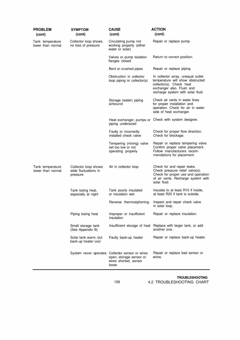
8/14/2019 Navy Maint. & Op of Active Solar Heating Sy
http://slidepdf.com/reader/full/navy-maint-op-of-active-solar-heating-sy 125/277

8/14/2019 Navy Maint. & Op of Active Solar Heating Sy
http://slidepdf.com/reader/full/navy-maint-op-of-active-solar-heating-sy 126/277
PROBLEM(cont)
Tank temperaturelower than normal
SYMPTOM CAUSE ACTION
(cont) (cont) (cont)
System never operates Control power off, switch Return switch to correct position,set wrong, or control isdefective
confirm power supply, checkcontrol and replace if defective.
System runs all thetime
System runs at odd Sensor wires too close totimes or relay 120V (or higher) lines orchatters other electrical “noise”
Gradual performancedecrease
Collectors shaded, orglazings dirty
Collector sensor or wiresshorted, storage sensor orwires open, sensor loose
Control switch set wrong,or control is defective
Condensation on inside ofcollector glazings
Pipe insulation degraded
Tempering valve defective
Heat exchanger scaling upwith hard water
Air in storage loop (water) Repair or replace air vents if faulty,
piping or tanks and/or reroute storage loop piping.
Repair or replace bad sensor orwires. Tighten connections.
Set control switch to correctposition, replace control ifdefective.
Reroute wires, and/or useshielded cable. Connect shieldto control case ground only.
Clear obstruction or cleanglazings when cool.
Check for weep holes, make surethey are open. If none exist,drill three 3/16” holes inbottom of affected collector.
Repair or replace pipe insulation.
Repair or replace tempering valve,confirm proper valve placement.
Descale heat exchanger
Drop in DHW pressure Drop in pressure of both Strainer, filter, valve or Clean or replace clogged unit.delivered to load
System not runningat appropriatetimes
hot and cold fixtures conditioner clogged or Return valves to proper position.closed in cold supply Check pressure reducing valve for
proper flow direction.
Drop in pressure of hot Valve closed in storage Return valves to proper position.fixtures only tank feed or supply line
Air in storage tank, or Repair or replace air vents and/ortank feed or supply line, reroute storage loop pipingor heat exchanger
System never operates Refer to “System never operates” above
System runs all the Refer to “System runs all the time” abovetime
System runs at oddtime or relaychatters
Refer to “System runs at odd times or relay chatters”above
TROUBLESHOOTING
4.2 TROUBLESHOOTING CHART 110
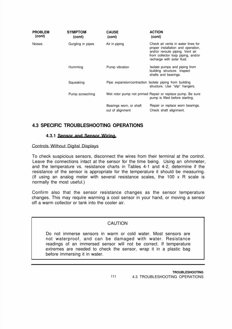
8/14/2019 Navy Maint. & Op of Active Solar Heating Sy
http://slidepdf.com/reader/full/navy-maint-op-of-active-solar-heating-sy 127/277
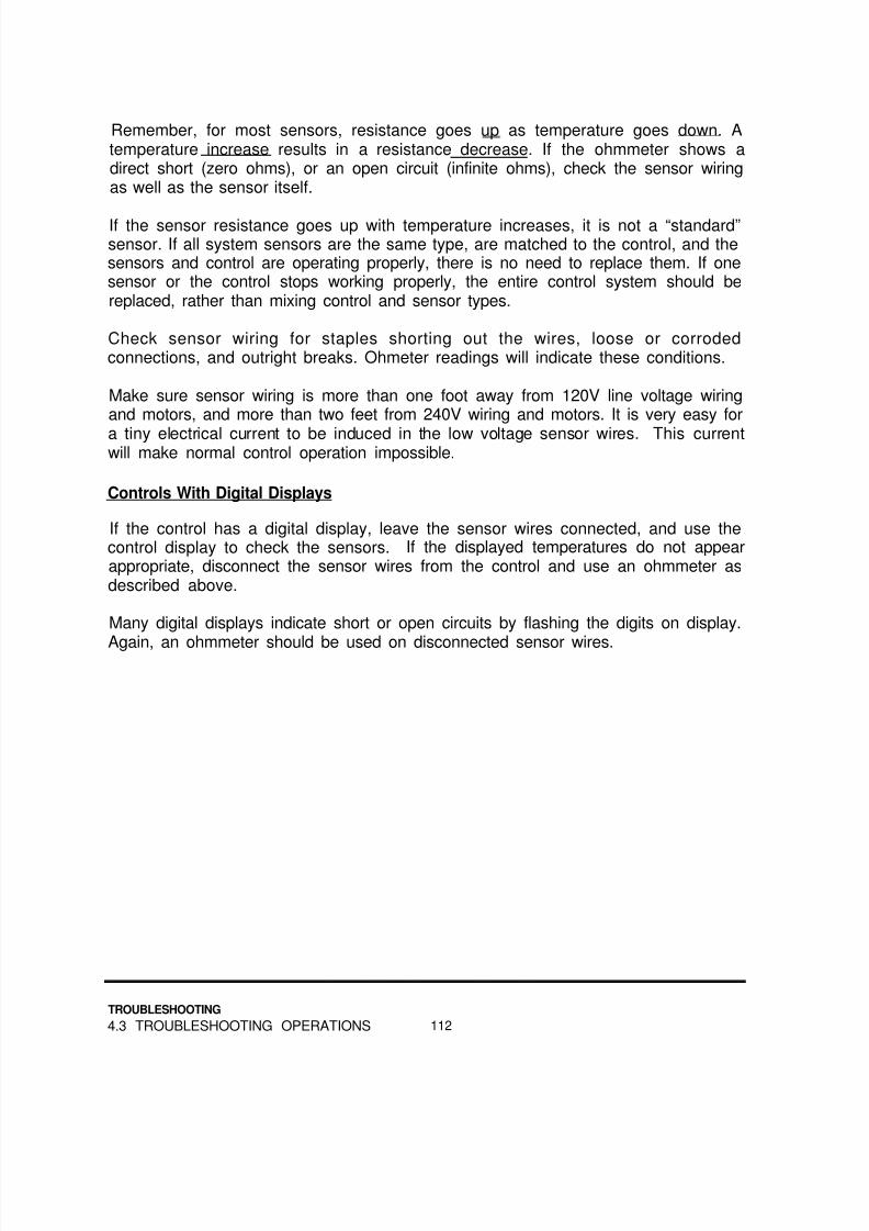
8/14/2019 Navy Maint. & Op of Active Solar Heating Sy
http://slidepdf.com/reader/full/navy-maint-op-of-active-solar-heating-sy 128/277
Remember, for most sensors, resistance goes up as temperature goes down. Atemperature increase results in a resistance decrease. If the ohmmeter shows adirect short (zero ohms), or an open circuit (infinite ohms), check the sensor wiringas well as the sensor itself.
If the sensor resistance goes up with temperature increases, it is not a “standard”sensor. If all system sensors are the same type, are matched to the control, and thesensors and control are operating properly, there is no need to replace them. If onesensor or the control stops working properly, the entire control system should bereplaced, rather than mixing control and sensor types.
Check sensor wiring for staples shorting out the wires, loose or corrodedconnections, and outright breaks. Ohmeter readings will indicate these conditions.
Make sure sensor wiring is more than one foot away from 120V line voltage wiringand motors, and more than two feet from 240V wiring and motors. It is very easy for
a tiny electrical current to be induced in the low voltage sensor wires. This currentwill make normal control operation impossible.
Controls With Digital Displays
If the control has a digital display, leave the sensor wires connected, and use thecontrol display to check the sensors. If the displayed temperatures do not appearappropriate, disconnect the sensor wires from the control and use an ohmmeter asdescribed above.
Many digital displays indicate short or open circuits by flashing the digits on display.
Again, an ohmmeter should be used on disconnected sensor wires.
TROUBLESHOOTING
4.3 TROUBLESHOOTING OPERATIONS 112

8/14/2019 Navy Maint. & Op of Active Solar Heating Sy
http://slidepdf.com/reader/full/navy-maint-op-of-active-solar-heating-sy 129/277
TABLE 4-1: Temperature vs. Resistance in Ohms for 10K Sensors
ºF ºC Resistance
32 0 .0 32 ,65434 1.1 30,85936 2 .2 29 ,17438 3 .3 27 ,59240 4 .4 26 ,10542 5 .6 24 ,709
4644 6.7 23,395
7 .8 22 ,16048 8 .9 20 ,99850 10.0 19,90352 11.1 18,87354 12.2 17,90356 13.3 16,988
58 14.4 16,126
6260 15.6 15,313
16.7 14,546
6664 17.8 13,822
18.9 13,13968 20.0 12,49370 21.1 11,88372 22.2 11,30774 23.3 10,76276 24.4 10,2477880
25.6 9,76026.7 9,298
82 27 .8 8 ,862
84 28 .9 8 ,44886 30 .0 8 ,0568890
31.1 7,68532 .2 7 ,333
9294
33 .3 6 ,99934 .4 6 ,683
9698
35 .6 6 ,38236 .7 6 ,097
100 37 .8 5,827102 38.9 5,5701 0 4 4 0 . 0 5 , 3 2 6
ºF ºC Resistance ºF ºC Resistance
106 41.1 5,093 180 82 .2 1 ,170108 42.2 4,873 182 83 .3 1 ,129110 43.3 4,663 184 84 .4 1 ,090112 44.4 4,464 186 85 .6 1 ,053114 45.6 4,274 188 86 .7 1 ,017116 46.7 4,093 190 87 .8 982118 47.8 3,921 192 88 .9 949120 48.9 3,758 194 90 .0 917122 50.0 3,602 196 91.1 886124 51.1 3,453 198 92 .2 857126 52.2 3,312 200 93 .3 828128 53.3 3,177 202 94 .4 801130 54.4 3,048 204 95 .6 775
132 55.6 2,925 206 96 .7 749134 56.7 2,808 208 97 .8 725136 57.8 2,697 210 98 .9 702138 58.9 2,590 212 100.0 679140 60.0 2,488 214 101.1 658142 61.1 2,391 216 102.2 637144 62.2 2,298 218 103.3 617146 63.3 2,209 220 104.4 597148 64.4 2,124 222 105.6 579150 65.6 2,043 224 106.7 561152 66.7 1,966 226 107.8 543154 67.8 1,891 228 108.9 527156 68.9 1,820 230 110.0 511
158 70.0 1,753 232 111.1 495160 71.1 1,688 234 112.2 480162 72.2 1,625 236 113.3 466164 73.3 1,566 238 114.4 452166 74.4 1,509 240 115.6 438168 75.6 1,454 242 116.7 425170 76.7 1,402 244 117.8 413172 77.8 1,351 246 118.9 401174 78.9 1,303 248 120.0 389176 80.0 1,257 250 121.1 378178 81.1 1,213
TROUBLESHOOTING
113 4.3 TROUBLESHOOTING OPERATIONS

8/14/2019 Navy Maint. & Op of Active Solar Heating Sy
http://slidepdf.com/reader/full/navy-maint-op-of-active-solar-heating-sy 130/277
TABLE 4-2: Temperature vs. Resistance in Ohms for 3K Sensors
ºF ºC Resistance º F ºC Resistance ºF ºC Resistance
3 2 . 0 0 9,810 105.8 41 1,540 179.6 82 35433.8 1 9,300 1 0 7 . 8 4 2 1,460 181 .4 83 34235.6 2 8,850 1 0 9 . 4 4 3 1,420 183.2 84 33337.4 3 8,430 111 .2 44 1,360 185 .0 85 32139.2 4 8,010 1 1 3 . 0 4 5 1,310 186 .8 86 31241.0 5 7,620 1 1 4 . 8 4 6 1,260 188 .6 87 30342.8 6 7,260 1 1 6 . 6 4 7 1,210 1 9 0 . 4 8 8 29344.6 7 6,900 118 .4 48 1,170 192.2 89 28446.4 8 6,570 1 2 0 . 2 4 9 1,120 194 .0 90 27548.2 9 6,270 122 .0 50 1,080 195 .8 91 26750 .0 10 5,970 123.8 51 1,040 1 9 7 . 6 9 2 25951.8 11 5,700 1 2 5 . 6 5 2 1,002 1 9 9 . 4 9 3 25153 .6 12 5,430 127 .4 53 966 201.2 94 243
55 .4 13 5,190 1 2 9 . 2 5 4 203 .0 95 2365 7 . 2 1 4 4,950 1 3 1 . 0 5 5
930879 204 .8 96 229
59 .0 15 4,710 132.8 56 864 206.6 97 22360 .8 16 4,500 1 3 4 . 6 5 7 208 .4 98 21562 .6 17 4,290 1 3 6 . 4 5 8
831801 210 .2 99 210
64 .4 18 4,110 1 3 8 . 2 5 9 212 .0 100 20466 .2 19 3,930 1 4 0 . 0 6 0
774747 213 .8 101 198
68 .0 20 3,750 1 4 1 . 8 6 1 720 215 .6 102 19269.8 21 3,570 1 4 3 . 6 6 2 696 217 .4 103 18771 .6 22 3,420 1 4 5 . 4 6 3 672 219 .2 104 18273 .4 23 3,270 147.2 64 648 221 .0 105 17675 .2 24 3,150 149.0 65 624 222.8 106 17177 .0 25 3,000 150.8 66 603 224 .6 107 16778 .8 26 2,870 152.6 67 582 226 .4 108 16280 .6 27 2,750 154.4 68 564 228 .2 109 15882 .4 28 2,630 156.2 6984 .2 29 2,520 158.0 70
543525
230 .0 110 153231.8 111 149
86 .0 30 2,420 159.8 71 507 233 .6 112 14587.8 31 2,320 161.6 72 492 235.4 113 14189 .6 32 2,220 163.4 73 474 237 .2 114 13791 .4 33 2,130 165.2 74 459 239 .0 115 1349 3 . 2 3 4 2,040 167.0 75 444 240 .8 116 13095 .0 35 1,960 168.8 76 429 242 .6 117 12796 .8 36 1,880 170.6 77 417 244.4 118 12398 .6 37 1,800 172.4 78 246 .2 119 120
100.4 38 1,730 174.2 79
402
390 248 .0 120 117102.2 39 1,670 176.0 80 378 249 .8 121 114104.0 40 1,600 177.8 81 366
TROUBLESHOOTING
4.3 TROUBLESHOOTING OPERATIONS 114

8/14/2019 Navy Maint. & Op of Active Solar Heating Sy
http://slidepdf.com/reader/full/navy-maint-op-of-active-solar-heating-sy 131/277
4.3.2 Controls,
Jumper Method
With all sensor wires disconnected and the control switch in the “automatic” position,
jumper the two terminals marked “Collector” (or “COLL,” etc.) (Figure 4-1). The solarloop pump (and water loop pump, if used) should come on.
FIGURE 4-1Checking On/OffOperation by theJumper Method
With the collector sensor terminals shorted, jumper the sensor terminals marked“Storage” (or “STOR,” etc.). The pump(s) should go off.
To test the high limit function, first determine the brand and type of differentialthermostat controlling the system. Most controls are 10K, that is their sensors have10,000 ohms resistance at 77°F. If you have any doubt about this, refer to the
system’s operation and maintenance manual. If one does not exist, remove asensor, give it time to come to room temperature, and measure its resistance withan ohmmeter.
Controls manufactured by Heliotrope General and Johnson Controls are not likely tobe 10K. Table 4-4 contains information on currently available controls.
Determine the high limit setting of the control from Table 4-4, the control labeling, orthe setting of the control’s high limit adjustment dial. (-This dial is usually on apotentiometer, sometimes called a “pot.“) (Figure 4-2)
TROUBLESHOOTING
115 4.3 TROUBLESHOOTING OPERATIONS

8/14/2019 Navy Maint. & Op of Active Solar Heating Sy
http://slidepdf.com/reader/full/navy-maint-op-of-active-solar-heating-sy 132/277

8/14/2019 Navy Maint. & Op of Active Solar Heating Sy
http://slidepdf.com/reader/full/navy-maint-op-of-active-solar-heating-sy 133/277
Use Table 4-1 or 4-2 to determine the right resistance to use to impersonate aparticular temperature. An abbreviated version, with resistor color codes ispresented in Table 4-3.
TABLE 4-3: Resistance and Color Codes for Typical High Limit Situations
Temperature 3K Resistance 10K Resistance
(ºF) and Color Code and Color Code
160
180
500 Ohms 1700 OhmsGreen, Red Brown, Violet, Red
350 Ohms 1200 OhmsOrange, Green, Black Brown, Red, Red
Control Tester Method
A more accurate method of testing differential thermostats is with a special testerdesigned for the purpose (Figure 4-4). Normally, these units have four leads orterminals. These are connected to the collector and storage sensor terminals of thecontrol. The tester supplies a calibrated resistance to the two sensor inputs.
Most of the available testers supply a fixed resistance to the storage terminals, andchange the resistance supplied to the collector terminals. The numbers on the
tester dial usually refer to the temperature difference between the storage andcollector terminals.
As the tester dial is slowly turned to greater differentials, the resistance supplied tothe collector sensor terminals is lowered. At the “on” differential, the control shouldturn on.
TROUBLESHOOTING
117 4.3 TROUBLESHOOTING OPERATIONS

8/14/2019 Navy Maint. & Op of Active Solar Heating Sy
http://slidepdf.com/reader/full/navy-maint-op-of-active-solar-heating-sy 134/277
FIGURE 4-4Solar Control Tester
Next, the dial is turned slowly downward to lower differentials. This increases theresistance shown to the collector sensor terminal. At the “off” differential, the controlshould shut off.
Many testers also include a high limit test function. Generally, the tester shorts outthe collector sensor’s terminals, to ensure the control is trying to run the system.
Then, the resistance supplied to the storage sensor terminals is reduced,impersonating a rising storage temperature. When the high limit is reached, thecontrol should shut off.
About Accuracy
The dials on most testers are not very accurate.use that instead of the numbers on the tester dial.
If the control has a digital display,
TROUBLESHOOTING
4.3 TROUBLESHOOTING OPERATIONS 118

8/14/2019 Navy Maint. & Op of Active Solar Heating Sy
http://slidepdf.com/reader/full/navy-maint-op-of-active-solar-heating-sy 135/277

8/14/2019 Navy Maint. & Op of Active Solar Heating Sy
http://slidepdf.com/reader/full/navy-maint-op-of-active-solar-heating-sy 136/277
4.3.3 Airbound Loops. If enough air bubbles gather at the high point of a pipingloop, a gap in the fluid may form.
Now that the piping loop is no longer completely filled, the circulating pump must
work against the effects of gravity. This usually means no flow occurs, since thepump was not designed for this condition. (Figure 4-5)
FIGURE 4-5An Airbound CollectorLoop
Piping with air in it is called “airbound.” Flow will be obstructed or stopped. Thisoccurs most often in collector loops, but is also possible in storage piping. Somecommon causes are:
o incomplete filling of the solar loop in closed loop systems
o leaks admitting air into solar loops
o ruptured expansion tank diaphragms.
o dissolved air in potable water forming bubbles which are not ventedout of piping and tanks (usually aggravated by bad or missing airvents).
TROUBLESHOOTING
4.3 TROUBLESHOOTING OPERATIONS 120
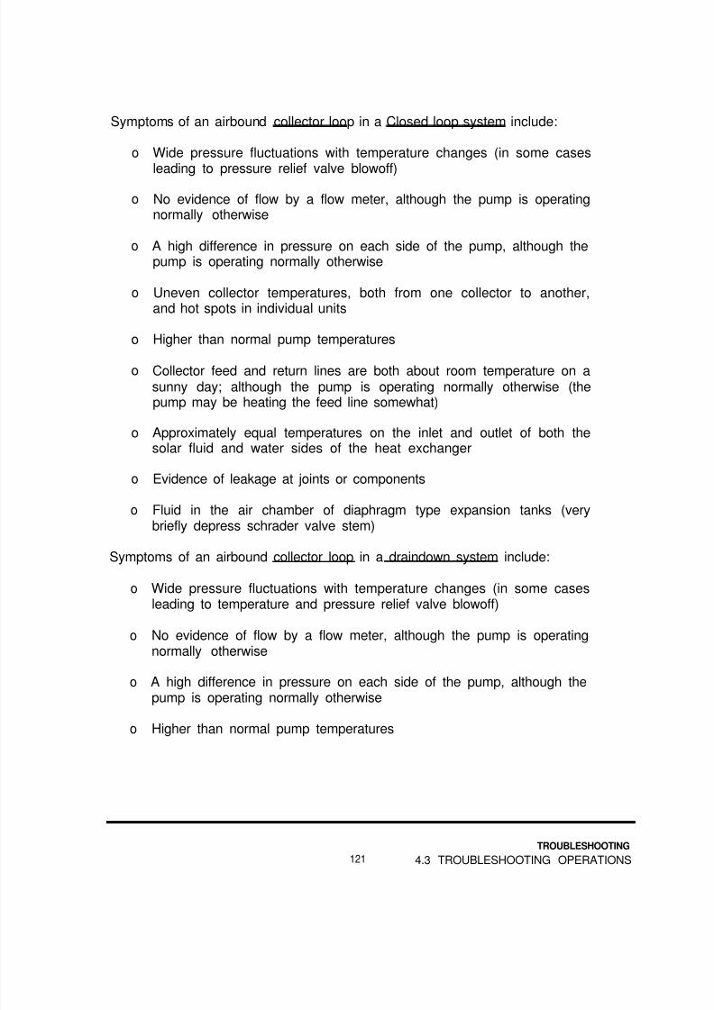
8/14/2019 Navy Maint. & Op of Active Solar Heating Sy
http://slidepdf.com/reader/full/navy-maint-op-of-active-solar-heating-sy 137/277
Symptoms of an airbound collector loop in a Closed loop system include:
o
o
o
o
o
o
o
o
o
Wide pressure fluctuations with temperature changes (in some casesleading to pressure relief valve blowoff)
No evidence of flow by a flow meter, although the pump is operatingnormally otherwise
A high difference in pressure on each side of the pump, although thepump is operating normally otherwise
Uneven collector temperatures, both from one collector to another,and hot spots in individual units
Higher than normal pump temperatures
Collector feed and return lines are both about room temperature on asunny day; although the pump is operating normally otherwise (thepump may be heating the feed line somewhat)
Approximately equal temperatures on the inlet and outlet of both thesolar fluid and water sides of the heat exchanger
Evidence of leakage at joints or components
Fluid in the air chamber of diaphragm type expansion tanks (very
briefly depress schrader valve stem)
Symptoms of an airbound collector loop in a draindown system include:
o Wide pressure fluctuations with temperature changes (in some casesleading to temperature and pressure relief valve blowoff)
o No evidence of flow by a flow meter, although the pump is operatingnormally otherwise
o A high difference in pressure on each side of the pump, although thepump is operating normally otherwise
o Higher than normal pump temperatures
TROUBLESHOOTING
121 4.3 TROUBLESHOOTING OPERATIONS

8/14/2019 Navy Maint. & Op of Active Solar Heating Sy
http://slidepdf.com/reader/full/navy-maint-op-of-active-solar-heating-sy 138/277

8/14/2019 Navy Maint. & Op of Active Solar Heating Sy
http://slidepdf.com/reader/full/navy-maint-op-of-active-solar-heating-sy 139/277
4.3.4 Pumps. Many “bad” pumps are actually not. Before draining fluid and tearingdown a pump, make sure the piping loop is free of air, no valves are closed, andthat the pump is getting electrical power.
Pump noise will indicate if the shaft is out of alignment, or the bearings are worn. Ifthe seals or gaskets are leaking, you can see the evidence. Check the servicerecord for the system: has the motor received necessary lubrication?
Check the system flow rate. This may be possible with a flow meter, a flow setterwith differential pressure gauge, or by comparing the pressure difference across thepump with the manufacturer’s pump curve. (To covert PSI into feet of head, multiplyPSI by 2.3.)
The next step should be to use a snap-around ammeter to measure the pumpmotor’s current draw during operation (Figure 4-6). If you know the correctamperage draw for the pump, you can quickly identify a number of problems. Insome cases, it may be possible to avoid draining the system and tearing down the
pump.
FIGURE 4-6
Using an Ammeteron a Solar Pump
TROUBLESHOOTING
123 4.3 TROUBLESHOOTING OPERATIONS

8/14/2019 Navy Maint. & Op of Active Solar Heating Sy
http://slidepdf.com/reader/full/navy-maint-op-of-active-solar-heating-sy 140/277
Use the following table to troubleshoot pump conditions with an ammeter.Remember to start with the highest scale and move downward until the amperagereading is in the upper half of the scale.
TABLE 4-5: Current Readings and Pump Problems
If Ammeter Reads:
Zero
Inspect for:
Power supply problemControl problemRelay or starter problemBroken motor lead
Thermal overload tripped
Too low(1/4 to 1/2 times
specifications)
Correct amount
Motor problemBroken or slipping shaft
Airbound loopClosed valve, backwards checkvalveBroken or slipping shaftDirection of motor rotation
Too high
(1 1/4 to1 1/2 timesspecifications)
Misaligned shaft
Worn bearingsForeign matter in voluteImpeller against volute wallMotor problem
Much too high(2 or more timesspecifications)
Locked rotor problem
If the ammeter reads zero, too high or much too high, also check relay contacts fordamage from excessive current draw.
TROUBLESHOOTING
4.3 TROUBLESHOOTING OPERATIONS 124

8/14/2019 Navy Maint. & Op of Active Solar Heating Sy
http://slidepdf.com/reader/full/navy-maint-op-of-active-solar-heating-sy 141/277
4.3.5 Flow Rates. If a flow meter is in the loop, compare the loop’s flow rate withthe rate called for in the system’s operation and maintenance manual. If thisinformation is not available, use Appendix B as a guide to the proper flow rate.
If a flow setter, with ports for measuring differential pressure, is in the loop, followthe instructions for that unit. Compare the reading to the system’s operation andmaintenance manual or Appendix B.
Some manufacturers supply pressure drop information for specific components,such as collectors or heat exchangers. If pressure gauges or measurement portsare available, this information can be used to determine flow rates.
The most common use of this technique involves reading the pressure on each sideof the pump when the pump is off, and again when it is operating.
After converting the pressure rise across the pump into feet of head, use themanufacturer’s pump curve, and estimate the flow rates. This technique isdescribed in greater detail in Section 3.1.4.
An estimate of flow rates can be made from the temperature changes through thesystem. Table 4-6 describes some typical design conditions. It assumes areasonably sunny day, with storage temperatures of 120°F. Collector looptemperatures are measured at the collector feed and return lines. Storage looptemperatures are measured at the storage water inlet and outlet at the heatexchanger.
Remember that the temperatures are affected not only by flow rates, but by the
amount of solar energy striking the collectors as well. Therefore, use these asrough guidelines only!
In general, the lower the collector loop temperature, the better. At first glance thismay not make sense. However, remember that if heat is being efficiently removedfrom the collectors, their temperature will be lower. High outlet temperatures fromthe collectors are an indication that too much heat is being left in them or thatcollectors are inefficient.
TROUBLESHOOTING
125 4.3 TROUBLESHOOTING OPERATIONS

8/14/2019 Navy Maint. & Op of Active Solar Heating Sy
http://slidepdf.com/reader/full/navy-maint-op-of-active-solar-heating-sy 142/277
TABLE 4-6: Flow Estimates from Temperature Changes
Collector Loop
If the temperature change is:
ZeroLess than 5°FBetween 5°F and 25°F
The flow rate probably is:
ZeroToo highIn the correctrange
More than 25ºF Too low
Storage Loop (on Drainback or Closed-Loop Systems)
If the temperature change is:
ZeroLess than 2°FBetween 2ºF and 10°F
More than 10°F
The flow rate probably is:
ZeroToo highIn the correctrangeToo low
4.3.6 Fluids.
Water Corrosiveness
Water can be corrosive for a number of reasons. The three most common causesare:
o low pH (acid water)o high dissolved oxygen contento high dissolved solids content
Cutting a small section of piping from an easily drained, easily repaired section ofpiping is sometimes the best way to determine if the water is corrosive. Knowledge
of local conditions is a traditional way to know that aggressive water is causing aproblem. Laboratory analysis is another choice, especially when it is difficult todetermine what is causing the water to be corrosive.
TROUBLESHOOTING
4.3 TROUBLESHOOTING OPERATIONS 126

8/14/2019 Navy Maint. & Op of Active Solar Heating Sy
http://slidepdf.com/reader/full/navy-maint-op-of-active-solar-heating-sy 143/277

8/14/2019 Navy Maint. & Op of Active Solar Heating Sy
http://slidepdf.com/reader/full/navy-maint-op-of-active-solar-heating-sy 144/277
The condition of the inhibitor can be checked by a manufacturer’s test kit or alaboratory. Another good method is to use pH tape or paper. If the pH is below 6,the fluid must be reinhibited or replaced. See section 3.1.6 for additional information.
FIGURE 4-7A Dowfrost Test Kitand a Dow OpticalRefractometer
TROUBLESHOOTING
4.3 TROUBLESHOOTING OPERATIONS 128

8/14/2019 Navy Maint. & Op of Active Solar Heating Sy
http://slidepdf.com/reader/full/navy-maint-op-of-active-solar-heating-sy 145/277
Make-Up Water Systems
If glycol-filled loops are equipped with automatic water make-up, glycol can leak outand be replaced by water. Eventually, the collector loop can freeze, causing severedamage. If the make-up water system has a gate valve, it should be closed andtagged so it will remain closed.
Fluid/Material Compatibility
Leaks at gaskets, seals, valve stems, hoses, etc. may be occurring because therubbers and plastics are being attacked by the fluid. This is most common withsynthetic and silicone oils, but it also happens with glycols.
Use the table in Appendix E to determine if the fluid and materials are compatible.This chart assumes the system is mostly copper tubing, and that relatively smallamounts of the other metals are used.
4.3.7 Piping Joints, Leaks in piping joints are not always obvious, sincethey may be covered with insulation. The insulation may also “channel” fluid faraway from the actual leak.
A “phantom leak” may occur if an automatic air vent is used with glycols or oils. Asthe fluid heats up, some of it vaporizes and leaves the system through the air vent.These vents, if installed, should be replaced with manual vents. At the very least,automatic vents should be tightly capped off during system operation, and thenreplaced the next time the system is drained.
It has been found that improperly soldered joints can hold pressure in glycol loopsfor months or even years after the installation. Eventually, the soldering flux whichplugged the holes in the joint finally melts out, and a leak results.
Improper types of thread sealants may hold pressure for a few months beforeleaking. Additional information on the use of thread sealants is provided in section5.2.2 and Appendix E.
The use of 95/5 tin/antimony solder on bronze or brass fittings may cause the zincto leach out of the fitting, causing porosity leaks. 96/4 silver solder should be usedinstead.
If a large number of joints are leaking in the collector loop, find out if 50/50 solderwas used. This solder’s melting point of 370°F is too low for the collector loop.Some plumbing inspectors have solder testers, and may be willing to test a samplefor you.
TROUBLESHOOTING
129 4.3 TROUBLESHOOTING OPERATIONS

8/14/2019 Navy Maint. & Op of Active Solar Heating Sy
http://slidepdf.com/reader/full/navy-maint-op-of-active-solar-heating-sy 146/277
Dissimilar metals in contact may create galvanic corrosion at the site of contact, orin soldered joints throughout the system. The most common example of this iswhen galvanized pipe hangers or perforated strap directly contact copper tubing.The resultant galvanic action corrodes the solder out of the joints.
4.3.8 Valves, Improperly positioned or configured valves can result in thesystem being unable to collect or deliver heat. If the storage tank is warm, theproblem is in the delivery components. If the tank is cold, the collection componentsare at fault.
Most tempering valves fail in such a way that all they deliver is cold water. Sincemost are improperly installed (directly above the tank), they eventually fail. -Checkalso for correct setting.
Solar loop check valve failure is a common problem. On a cold night after a warm
day, the feed and return temperatures should be equal. If there is a temperaturedifference of more than 5ºF, the check valve is not stopping the loss of heat byforward or reverse thermosiphoning. (Figure 4-8)
On pool heating systems, the diverting valve may be “pilot operated.” The actualopening and closing of the valve is done by suction or pressure supplied by the poolpump. Suction is supplied by tubing connected to the inlet piping of the pump.Pressure is supplied by a tube from the pump’s discharge side.
FIGURE 4-8ReverseThermosiphoning in aClosed-Loop System
TROUBLESHOOTING
4.3 TROUBLESHOOTING OPERATIONS 130

8/14/2019 Navy Maint. & Op of Active Solar Heating Sy
http://slidepdf.com/reader/full/navy-maint-op-of-active-solar-heating-sy 147/277
The pressure and/or suction may be operated directly by the system control. Inother cases, the opening and closing may be triggered by an electrical signal fromthe control. This is usually low voltage: 12 or 24 volts. Check both the tubing andany wiring when troubleshooting pool heating systems control valves.
4.3.9 Heat Exchangers, A reduction in heat exchanger performance may becaused by scale from hard water, glycol sludge or reduced flow due to an airboundloop, improperly positioned valve or defective pump. Any of these will cause anoverall rise in collector loop temperatures.
Leaks may be caused by improper installation techniques or materials, physicalstresses, corrosive fluid or incompatible seals materials.
Another common cause of leaks is freezing. If the solar fluid is circulating below
32ºF, it can easily freeze the water in the heat exchanger. This circulation may be
from reverse thermosiphoning or a defective control or sensor running the system atnight.
If city water pressure is entering the solar loop in closed loop or draindown systems,the loop pressure may be much higher or lower than normal.
4.3.10 Insulation, Inadequate, damaged or missing piping insulation willreduce system performance considerably. However, before deciding pipe insulationis the problem, make sure:
o flow rates are proper and balancedo collectors are clean and unshadedo controls and sensors are operating properlyo tank and heat exchanger piping is correcto valves are properly positioned
Tanks losing heat overnight may have inadequate insulation, but also check for:
o reverse thermosiphoningo “invisible loads” (such as a dripping hot water faucet)o inaccurate or poorly placed tank thermometero defective control or sensor running the system at night
Wet insulation offers very little resistance to heat flow, but may appear intact. If aleak occurs in a system, check all the pipe insulation to be sure it is dry.
TROUBLESHOOTING
131 4.3 TROUBLESHOOTING OPERATIONS

8/14/2019 Navy Maint. & Op of Active Solar Heating Sy
http://slidepdf.com/reader/full/navy-maint-op-of-active-solar-heating-sy 148/277
4.3.11 Gauges. Gauges may be checked in two ways. The first is to bringthe gauge to a standard condition. For pressure gauges, remove them from thesystem. They should read zero. For thermometers, take them out and put. them inice water or boiling water, depending on their temperature range.
The second method is comparison. Replace the suspect gauge with one you knowto be accurate. This is more practical with thermometers than with pressuregauges.
A typical problem with thermometers is their location. For example, thethermometer on a storage tank of 120 gallon capacity or less is usually installed inthe outlet piping of the tank. If it is more than a few inches from the tank, the onlytime it will accurately report tank temperature is when water from the tank runs by it.
4.3.12 Storage Tanks, Problems with storage tanks may actually be causedby piping errors. One of the most common is mixing up inlets and outlets. Another
problem is the length of dip tubes. If they are too short or too long, the tank may notbe able to store or deliver its full heat capacity. (Figure 4-9)
FIGURE 4-9Correct Dip TubeLengths in a “Four-Stub
Tank
If the dip tubes are plugged with scale, or collapsed from heat, the system will notstore heat properly. Higher collector loop temperatures is one symptom of this.
Another problem may be an incorrectly positioned auxiliary heating element. Forthe system to operate properly, auxiliary elements must be in the upper half of thetank.
Finally, frequent replacement of anode rods indicates highly corrosive water or anexposed metal surface.
TROUBLESHOOTING
4.3 TROUBLESHOOTING OPERATIONS 132

8/14/2019 Navy Maint. & Op of Active Solar Heating Sy
http://slidepdf.com/reader/full/navy-maint-op-of-active-solar-heating-sy 149/277
4.4 Questions for Self-study
Instructions: Choose the one answer you believe is correct. Answers to questionsare in Appendix F.
4-1 What is the best way to warm up a thermistor sensor to test it?
a) Use the flame of a soldering torchb) Warm it in your handc) Drop it into hot waterd) Bake it in an oven
4-2 A thermistor sensor is removed from a hot collector and left in the shade behind
the collector; What should happen to its resistance?
a) Go to zerob) Go downc) Go upd) Nothing
4-3 With all sensors disconnected from a functional differential thermostat, a jumperwire is placed across the collector sensor terminals. What should happen?
a) The pump should stop runningb) The pump should run for a few minutes, then stopc) The pumps should start runningc) Nothing
4-4 The wiring to a collector sensor is shorted out. What will happen?
a) The pump will run all the timeb) The pump will run only at nightc) The pump will never rund) The pump will run normally
TROUBLESHOOTING
133 4.4 QUESTIONS FOR SELF-STUDY

8/14/2019 Navy Maint. & Op of Active Solar Heating Sy
http://slidepdf.com/reader/full/navy-maint-op-of-active-solar-heating-sy 150/277
4-5 The wiring to a storage sensor is shorted out. What will happen?
a) The pump will run all the timeb) The pump will run only at nightc) The pump will never run
d) The pump will run normally
4-6 A storage high limit of 160 degrees is desired for a 10K control. Whatresistance should be used to “impersonate” this temperature?
a) 13,500 ohmsb) 10,000 ohmsc) 1,700 ohmsd) 1,170 ohms
4-7 Which is the most accurate and useful dial or readout when testing controlsand sensors?
a) Resistor color codeb) Analog ohmmeterc) Control tester diald) Control digital readout
4-8 Which of these is a symptom of an airbound collector loop in a closed-loopsystem?
a) The collector feed temperature is greater than the return temperatureb) The collector feed and return temperatures are the samec) Erratic control operationd) The pump’s current draw is much too low
4-9 A piping loop has no apparent flow, but the pump’s current draw is correct.What is the most likely problem?
a) Tripped circuit breaker
b) Worn pump bearingsc) Closed valve in loopd) Locked pump rotor
TROUBLESHOOTING
4.4 QUESTIONS FOR SELF-STUDY 134

8/14/2019 Navy Maint. & Op of Active Solar Heating Sy
http://slidepdf.com/reader/full/navy-maint-op-of-active-solar-heating-sy 151/277

8/14/2019 Navy Maint. & Op of Active Solar Heating Sy
http://slidepdf.com/reader/full/navy-maint-op-of-active-solar-heating-sy 152/277
4-15 What can cause galvanic corrosion in a copper piping loop?
a) Small amounts of cast ironb) Galvanized pipe hangers
c) Stainless steel pipe hangersd) Teflon-based thread sealants
4-16 At night the collector return line is cooler than the feed line. What is the mostlikely problem?
a) Reverse thermosiphoningb) Airbound loopc) Short in collector sensor wiringd) Short in storage sensor wiring
TROUBLESHOOTING
4.4 QUESTIONS FOR SELF-STUDY 136

8/14/2019 Navy Maint. & Op of Active Solar Heating Sy
http://slidepdf.com/reader/full/navy-maint-op-of-active-solar-heating-sy 153/277
5.0REPAIR
What You Will Find in This Chapter
This chapter includes information on the repair or replacement of solar systemcomponents. The first section lists common components and whether to repair orreplace them. Then, specific procedures for particular components are described.The chapter ends with a sample repair record sheet.
System inspection and troubleshooting are not covered. This chapter assumes thereader has already determined what the problem is, and needs information on howto fix it.
The information in Appendices A, B and C will be helpful in performing theoperations described in this chapter. A worksheet is provided at the end of thischapter.
5.1 REPAIR OR REPLACE?
Some components, such as collector glazings, can never be repaired, and must bereplaced. Others, such as mounting racks, are usually repaired rather thanreplaced.
However, most components can be repaired or replaced. In general, the decision torepair or replace is based on:
o availability of replacement partso lead time for replacement partso cost of replacement partso difficulty of repair
137
REPAIR
5.1 REPAIR OR REPLACE

8/14/2019 Navy Maint. & Op of Active Solar Heating Sy
http://slidepdf.com/reader/full/navy-maint-op-of-active-solar-heating-sy 154/277
Table 5-1 lists system components and describes the usual choice of repair orreplacement.
TABLE 5-1: Typical Repair/Replace Choices
COMPONENT REPAIR REPLACE
Collectors
Glazings Never Always
Frames Rarely Usually
Glazing Seals Sometimes Sometimes
Header Gaskets Sometimes Sometimes
Interior Insulation Never AlwaysMounting Hardware Sometimes Sometimes
Frame Grounding Usually RarelySensor Never Always
Absorber Plate (Leaking) Sometimes UsuallyAbsorber Plate (Coating damage) Rarely Usually
Exterior Piping
Insulation Usually RarelyHangers Sometimes Sometimes
Leaks Usually RarelyValves Rarely Usually
Interior Piping
InsulationHangers
Usually RarelySometimes Sometimes
REPAIR
5.1 REPAIR OR REPLACE 138

8/14/2019 Navy Maint. & Op of Active Solar Heating Sy
http://slidepdf.com/reader/full/navy-maint-op-of-active-solar-heating-sy 155/277
TABLE 5-1 (Continued)
COMPONENT REPAIR REPLACE
Interior Piping (cont)
Leaks Usually Rarely
Valves Rarely Usually
Pressure GaugesThermometers
RarelyNever
UsuallyAlways
PT PlugsExpansion Tanks
NeverRarely
AlwaysUsually
Pumps. Wet Rotor
Impellers (usually part of cartridge) Never AlwaysRotors (usually part of cartridge) Never Always
Stators (“Cans”)Volutes
NeverRarely
AlwaysUsually
CapacitorsFlanges
NeverRarely
AlwaysUsually
Flange GasketsBody Seals
NeverNever
AlwaysAlways
Pumps. Separate Motor
Motors NeverVolutes Rarely
AlwaysUsually
Impellers
Bearings
Rarely
Never
Usually
Always
CapacitorsFlanges
NeverRarely
AlwaysUsually
139
REPAIR
5.1 REPAIR OR REPLACE
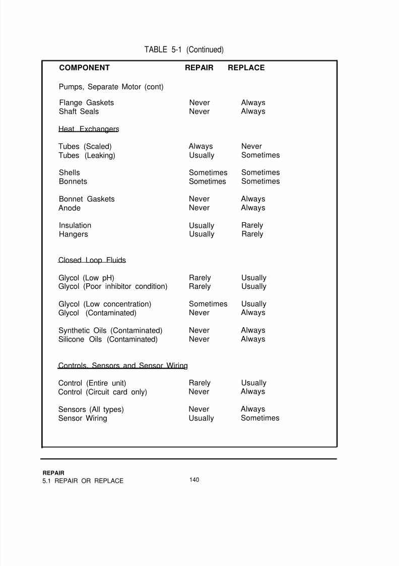
8/14/2019 Navy Maint. & Op of Active Solar Heating Sy
http://slidepdf.com/reader/full/navy-maint-op-of-active-solar-heating-sy 156/277
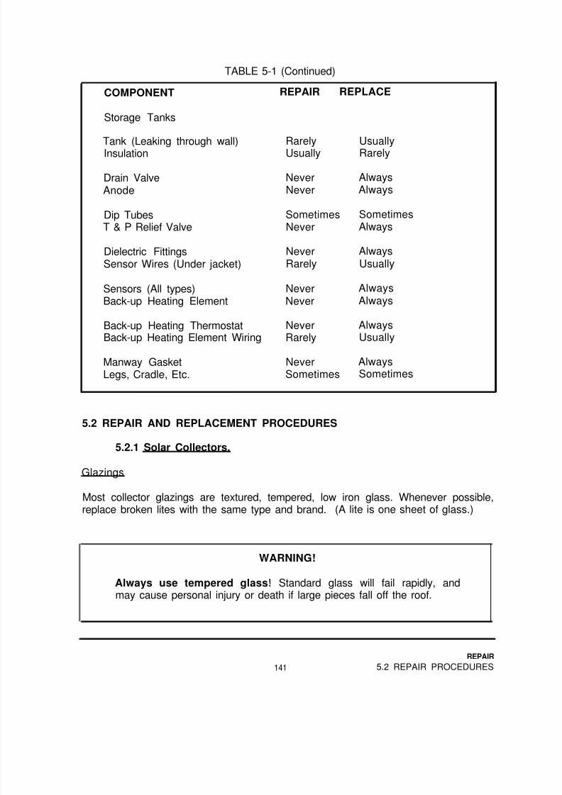
8/14/2019 Navy Maint. & Op of Active Solar Heating Sy
http://slidepdf.com/reader/full/navy-maint-op-of-active-solar-heating-sy 157/277

8/14/2019 Navy Maint. & Op of Active Solar Heating Sy
http://slidepdf.com/reader/full/navy-maint-op-of-active-solar-heating-sy 158/277
Tempered glass is cut to size before tempering. Any attempt to cut tempered glasswill break it.
Handling and Moving Glass Glazings
Leave replacement glazings packed as they were shipped until you are at the jobsite. Repack unused replacements before transporting them back to storage.
Always carry glass vertically (upright) (Figure 5-1). Be very careful not to scratch theglass. A deep scratch will cause the glass to shatter the first time it gets hot. Ifpossible, use suction cups with handles designed specifically for moving glass.
FIGURE 5-lCarrying GlassProperly
Remove the small pieces of broken glazing with a shop vacuum. Avoid rubbing offthe black absorber surface with the hose or the glass “crumbs.” Remove the capstrips holding down the glazing, and remove any pieces of glass and old sealant.
REPAIR
5.2 REPAIR PROCEDURES 142

8/14/2019 Navy Maint. & Op of Active Solar Heating Sy
http://slidepdf.com/reader/full/navy-maint-op-of-active-solar-heating-sy 159/277

8/14/2019 Navy Maint. & Op of Active Solar Heating Sy
http://slidepdf.com/reader/full/navy-maint-op-of-active-solar-heating-sy 160/277

8/14/2019 Navy Maint. & Op of Active Solar Heating Sy
http://slidepdf.com/reader/full/navy-maint-op-of-active-solar-heating-sy 161/277
FIGURE 5-3Weep Hole
Locations
Insulation with more moisture requires opening up the collector and wiping off theinside of the glazing. If dry weather is anticipated, leave off the glazing for a weekand let the collector dry itself out.
If rain or snow is possible, or if the insulation is completely soaked, remove it andreplace it.
Sometimes, wet fiber glass insulation can be removed from behind the absorberplate by tearing it off like a paper towel being torn off the roll. Make sure the
replacement insulation completely fills the void.
Foam insulation can be replaced with sheets of foil-faced, fiber glass-reinforcedpolyisocyanurate foam. Use no other foam material! Be sure the replacementinsulator is the same thickness as the original insulation. There are many brands ofthis type of material.
Fiber glass insulation must be replaced with an unfaced low-binder batt designed forsolar use. Regular unfaced fiber glass will outgas the excess binder. This will fogthe glazing in a matter of a few weeks.
145
REPAIR
5.2 REPAIR PROCEDURES

8/14/2019 Navy Maint. & Op of Active Solar Heating Sy
http://slidepdf.com/reader/full/navy-maint-op-of-active-solar-heating-sy 162/277
CAUTION
Do not, under any circumstances, use kraft paper-faced insulation ofany kind in solar collectors. There is a very real possibility of the
paper catching fire.
Mounting Hardware
Tighten all loose hardware, and replace any missing parts. Look across collectorarrays to find and correct misaligned collectors. This is one or more collectorsfacing in a slightly different direction. It has been compared to the appearance ofbutterfly wings. (Figure 5-4)
FIGURE 5-4Misaligned
Collectors
If any of the connections between the mounting hardware and the building are looseor missing, repair them. Examine the other mounting points to determine how to dothis. Remember, the biggest load on these points is upward, as the wind tries to liftthe collectors.
REPAIR
5.2 REPAIR PROCEDURES 146

8/14/2019 Navy Maint. & Op of Active Solar Heating Sy
http://slidepdf.com/reader/full/navy-maint-op-of-active-solar-heating-sy 163/277

8/14/2019 Navy Maint. & Op of Active Solar Heating Sy
http://slidepdf.com/reader/full/navy-maint-op-of-active-solar-heating-sy 164/277
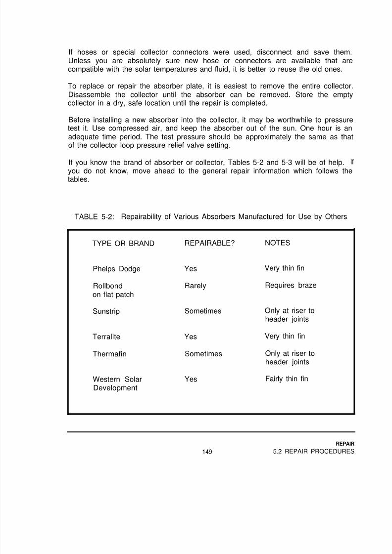
8/14/2019 Navy Maint. & Op of Active Solar Heating Sy
http://slidepdf.com/reader/full/navy-maint-op-of-active-solar-heating-sy 165/277
If hoses or special collector connectors were used, disconnect and save them.Unless you are absolutely sure new hose or connectors are available that arecompatible with the solar temperatures and fluid, it is better to reuse the old ones.
To replace or repair the absorber plate, it is easiest to remove the entire collector.
Disassemble the collector until the absorber can be removed. Store the emptycollector in a dry, safe location until the repair is completed.
Before installing a new absorber into the collector, it may be worthwhile to pressuretest it. Use compressed air, and keep the absorber out of the sun. One hour is anadequate time period. The test pressure should be approximately the same as thatof the collector loop pressure relief valve setting.
If you know the brand of absorber or collector, Tables 5-2 and 5-3 will be of help. If
you do not know, move ahead to the general repair information which follows thetables.
TABLE 5-2: Repairability of Various Absorbers Manufactured for Use by Others
TYPE OR BRAND
Phelps Dodge
Rollbondon flat patch
Sunstrip
Terralite
Thermafin
Western Solar
Development
REPAIRABLE? NOTES
Yes
Rarely
Very thin fin
Requires braze
Sometimes Only at riser toheader joints
Yes
Sometimes
Very thin fin
Only at riser toheader joints
Yes Fairly thin fin
149
REPAIR
5.2 REPAIR PROCEDURES

8/14/2019 Navy Maint. & Op of Active Solar Heating Sy
http://slidepdf.com/reader/full/navy-maint-op-of-active-solar-heating-sy 166/277
TABLE 5-3: Repairability of Various AbsorbersManufactured by Collector Manufacturers
TYPE OR BRAND
American SolarKing SG-15
REPAIRABLE?
Rarely
NOTES
Rollbond plate
Colt C-141
Daystar 1400,1600, 1600 TLS
Yes
Yes
Fairly thin fin
Fairly thick fin
Gulf Thermal Yes Fin wrappedaround tube
Grumman Sunstream121, 232, 221,232, 321A, 332A
Yes May be hard toremove fin
Morning Star
Revere
Yes
Sometimes
Fairly thin fin
Only at riser toheader joints
Sunworks
U.S. Solar
Yes
Yes
Fairly thin fin
May be hard to
remove fin
Western SolarDevelopment
Sometimes Some models use“D” shaped tube
If the leak is at the joint between the header and a riser, it must be rebrazed.Carefully remove any absorber fin which covers the leaking joint. On someabsorbers it is possible to use the “feather of a torch on the back side to melt solderholding the fin on the tubes, then bend the fin back. On other absorbers, careful
work with tin snips will expose the joint.
The joint must be thoroughly cleaned and rebrazed (Figure 5-7). Use phoscopper orsilver bearing brazing alloy. Do not use solder! Even silver solder will not hold up tothe combination of temperature and mechanical stress this joint undergoes.
REPAIR
5.2 REPAIR PROCEDURES 150

8/14/2019 Navy Maint. & Op of Active Solar Heating Sy
http://slidepdf.com/reader/full/navy-maint-op-of-active-solar-heating-sy 167/277
FIGURE 5-7Rebrazing a
Header/Riser Joint
If possible, replace the fin. Do not bother to completely reattach it to the tubes. It isnot normally possible to restore the thermal connection after removing the fin.
If the leak is in the riser tube, and the fin can be removed from the tube, it can berepaired. The best approach is to cut out the fin and the damaged portion of thetube. Braze (not solder!) a section of new tubing into place with two couplings(Figure 5-8).
FIGURE 5-8Repairing a Riser
Leak
151
REPAIR
5.2 REPAIR PROCEDURES

8/14/2019 Navy Maint. & Op of Active Solar Heating Sy
http://slidepdf.com/reader/full/navy-maint-op-of-active-solar-heating-sy 168/277
Before replacing the absorber in the collector, spray black high-temperature(barbecue or stove) paint on the insulation where the hole in the fin will be. Use thesame paint on the repaired section of the tube.
Before installing a repaired absorber into the collector, it may be worthwhile topressure test it. Use compressed air, and keep the absorber out of the sun. Onehour is an adequate time period. The test pressure should be at approximately thesame pressure as the collector loop pressure relief valve release pressure.
Frame Ground
Every collector with a sensor must have its frame grounded. This ground helpsprevent damage to the system control.
The typical grounding method is simple. A short piece of 12 or 14 gauge copper
wire is stripped at each end about two inches. One end is hose clamped to anabsorber plate header. The other end is connected to the collector frame. Theframe connection usually involves the collector mounting hardware (Figure 5-9).
FIGURE 5-9A Properly GroundedCollector
After installing or reconnecting this ground, use an ohmmeter to make sure there isa solid electrical connection between the absorber piping and the frame. Cover the
junction between the aluminum frame and the copper wire with silicone sealant toreduce galvanic corrosion.
REPAIR
5.2 REPAIR PROCEDURES 152

8/14/2019 Navy Maint. & Op of Active Solar Heating Sy
http://slidepdf.com/reader/full/navy-maint-op-of-active-solar-heating-sy 169/277
At the mechanical room, use the ohmmeter to confirm that the collector loop pipingis connected to ground. If it is not, hose clamp another section of copper wire to thecollector return line. Run this over to a mechanical ground, usually the same oneused for the building electrical system.
Remember that the surface of anodized or painted aluminum does not conductelectricity. Anodized aluminum may not appear to have any coating.
Collector Sensor
Three important things to remember about replacing the collector sensor are:
o Keep the sensor close to the absorber for more accuracyo Insulate the sensor for more accuracyo Protect the sensor from weather and mechanical stress
Install the differential thermostat’s “collector” sensor at the collector outlet header.One acceptable method is to push the “tongue” of the sensor under the grommet ofthe outlet pipe. Use a stainless steel hose clamp to secure the sensor(Figure 5-1 0). Do not overtighten the clamp!
FIGURE 5-10Collector Sensor
Installation
153
REPAIR
5.2 REPAIR PROCEDURES

8/14/2019 Navy Maint. & Op of Active Solar Heating Sy
http://slidepdf.com/reader/full/navy-maint-op-of-active-solar-heating-sy 170/277

8/14/2019 Navy Maint. & Op of Active Solar Heating Sy
http://slidepdf.com/reader/full/navy-maint-op-of-active-solar-heating-sy 171/277
FIGURE 5-11Inadequate Pipe
Insulation
Fiber glass and rigid foams must be jacketed. Section 2.5.8 has more informationon pipe insulation and jacketing materials.
Interior piping must also be insulated, but jacketing or painting is only required forappearance, color coding, or protection from people.
Adequate insulation means at least R-4, but it is desirable to have R-7 or more.
Use materials and techniques similar to those used originally to repair pipinginsulation. Do not use duct or electrical tape to hold the insulation together. Thismethod will fail in a few months, making the system look and perform worse thanever.
Replace missing hangers, and tighten loose ones. Be sure galvanized hangers arenot in direct contact with copper tubing.
The galvanic corrosion resulting from direct contact will “eat” the solder out of the joints. Provide adequate cradles for the pipe insulation to keep it from beingcrushed.
155
REPAIR
5.2 REPAIR PROCEDURES

8/14/2019 Navy Maint. & Op of Active Solar Heating Sy
http://slidepdf.com/reader/full/navy-maint-op-of-active-solar-heating-sy 172/277
Leaks
Leaking soldered joints must be repaired with a high-temperature solder, not 50/50(Tin/Lead)! 95/5 (Tin/Antimony) can be used on all copper to copper joints. Joints
involving bronze should be repaired with 96/4 (Tin/Silver) solder. The use of 50/50will result in joint failure within a few months, and may violate plumbing code.
WARNING!
Glycols and oils will burn when exposed to soldering torchflames. Always drain the collectors before un-soldering joints!Before heating the joints, remove the air vent, to allow fluid vapors toescape. As the joint comes apart, be prepared for a brief flare. Keepa fire extinguisher with you- not down in the truck!
Threaded joints in piping filled with glycols or synthetic oils must use teflon-basedthread sealants. Teflon tape, or Rectorseal #100 are two good choices. The onlyappropriate sealant for threads exposed to silicone oils is fluorosilicone.
Brazed joints, and flared or compression fittings are all acceptable, but are rarelyused because they are less convenient than soldered or threaded joints.
Be sure to completely reinsulate the repaired piping.
Valves
Normally, valves with leaking stem seals can be repaired by tightening the packingnut. If the leak is caused by an incompatible solar fluid, the valve should bereplaced with one with more compatible materials.
Leaks at valve inlets or outlets should be repaired the same way other leaks are.Be careful to drain the solar fluid before applying a torch flame. Do not overheat thevalve and warp the seat or damage the internal seals.
Follow the recommendations for thread sealants and solder types in the precedingsection. If one valve or piping component in a loop is leaking, it may be worthwhileto replace all similar units in that loop while the fluid is drained.
REPAIR
5.2 REPAIR PROCEDURES 156

8/14/2019 Navy Maint. & Op of Active Solar Heating Sy
http://slidepdf.com/reader/full/navy-maint-op-of-active-solar-heating-sy 173/277
Whenever replacing a valve in a horizontal line, drop the valve handle 15º fromhorizontal as shown in Figure 5-12. This allows any leakage to drip off the handleand be seen, rather than soaking into the insulation undetected. Globe valves mustnot be used!
FIGURE 5-12Valve Installation
CAUTION
Unless a component is specifically for use in solar heatingsystems, confirm that body materials, construction, seals and gasketsare appropriate for the solar fluid being used and the highest potential
temperatures and pressures for the system. As an example, most ofthe standard gate valve packings are quickly degraded by syntheticoils. The inevitable result is a loss of fluid, leading to more seriousconsequences.
Collector Loop Flow Balancing
Ball valves are usually installed in the inlets of collector arrays for balancing flowrates. Every separate array of collectors should have a thermometer or the
equivalent in its outlet. When all the outlet temperatures are identical, the flow ratesare balanced. This works even when the arrays have different numbers ofcollectors.
157
REPAIR
5.2 REPAIR PROCEDURES

8/14/2019 Navy Maint. & Op of Active Solar Heating Sy
http://slidepdf.com/reader/full/navy-maint-op-of-active-solar-heating-sy 174/277
Balancing must be done on a sunny day when the system is operating. Reduce theflow slightly through the array with the lowest outlet temperature. Wait three or fourminutes, and recheck all the array outlet temperatures. Continue balancing andwaiting until all the temperatures are within five degrees of each other.
NOTE
Close the balancing valves as little as possible. Reducing the flowrate through the collectors reduces their efficiency.
WARNING!
Never install valves in a way that could allow the isolation of the solarcollectors from pressure relief valves and/or expansion tanks.Collectors have been completely destroyed by bursting in this way.
Pressure Gauges and Thermometers
Broken, leaking or inaccurate pressure gauges and thermometers are almost
always replaced. The only practical exception to this is the occasional pressuregauge which can be recalibrated.
A recalibratable pressure gauge has a removable glass lens and ring (to hold theglass on). It also has a screwdriver slot in the center of the gauge needle orelsewhere on the face (Figure 5-13).
REPAIR
5.2 REPAIR PROCEDURES 158

8/14/2019 Navy Maint. & Op of Active Solar Heating Sy
http://slidepdf.com/reader/full/navy-maint-op-of-active-solar-heating-sy 175/277
FIGURE 5-13A RecalibratablePressure Gauge
Courtesy of Marsh Instrument Co.
To make an adjustment, let all the system pressure out, and turn the calibrationscrew until the needle indicates zero.
Pressure Relief Valves
When replacing pressure relief valves, be sure the release pressure of thereplacement is the same as the system designer specified. Repipe discharge pipingfollowing local code requirements.
CAUTION
Never use a temperature and pressure relief valve in thecollector loop of closed loop systems. The valve will open at sometime, due to normal temperatures, causing a loss of solar fluid.
159
REPAIR
5.2 REPAIR PROCEDURES

8/14/2019 Navy Maint. & Op of Active Solar Heating Sy
http://slidepdf.com/reader/full/navy-maint-op-of-active-solar-heating-sy 176/277
Expansion Tanks
Leaks at expansion tank inlet fittings are repaired the same way as other threadedfittings. Generally, a crack in the tank wall at the inlet fitting indicates a need toreplace the entire tank.
Sometimes they can be welded, but it is rarely worth the effort and cost. Whenevera tank without a diaphragm must be replaced, use one with a diaphragm.
Tank wall leaks are usually cause for tank replacement. If the wall appearscorroded, check the condition of the fluid which caused it.
If the tank holds water, appropriate water conditioning may be needed. If the fluid isa glycol, it may be acidic. In this case, the loop should be flushed and refilled with afresh glycol/water mixture. Dispose of used solar fluids in accordance with localrequirements.
If a diaphragm-type expansion tank has any fluid in the air compartment, it must bereplaced. This is usually found by momentarily depressing the stem of the schradervalve. Any fluid discharged from the air compartment means the diaphragm hasbroken, or is disconnected from the tank wall.
Be aware that sometimes fluid leaking from a loose connection at the top of the tankwill “sneak” down the back side of the tank. The dripping fluid at the bottomschrader valve fitting may not really be coming out of the bottom of the tank.
Occasionally, a schrader valve will loosen up, releasing all the pressure from the aircompartment. Use an automotive valve stem tool to tighten up the schrader valve,
and repressurize the air side of the tank to the correct pressure listed in Table 5-5.
Refilling the air side to the appropriate pressure must be done when
NOTE
there is no fluid pressure on the other side of the diaphragm. SeeTable 5-5 for further information on system charging pressures.
REPAIR
5.2 REPAIR PROCEDURES 160
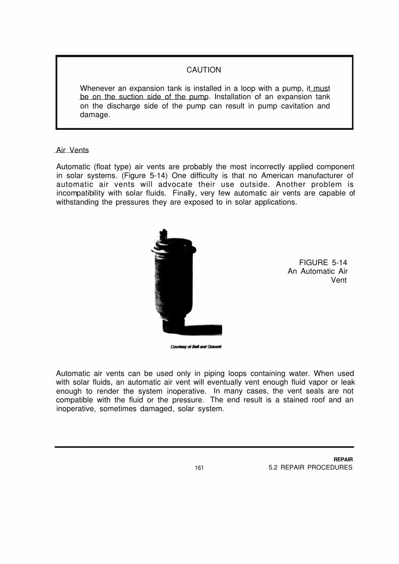
8/14/2019 Navy Maint. & Op of Active Solar Heating Sy
http://slidepdf.com/reader/full/navy-maint-op-of-active-solar-heating-sy 177/277
CAUTION
Whenever an expansion tank is installed in a loop with a pump, it must
be on the suction side of the pump. Installation of an expansion tankon the discharge side of the pump can result in pump cavitation anddamage.
Air Vents
Automatic (float type) air vents are probably the most incorrectly applied componentin solar systems. (Figure 5-14) One difficulty is that no American manufacturer ofautomatic air vents will advocate their use outside. Another problem isincompatibility with solar fluids. Finally, very few automatic air vents are capable ofwithstanding the pressures they are exposed to in solar applications.
FIGURE 5-14An Automatic Air
Vent
Automatic air vents can be used only in piping loops containing water. When usedwith solar fluids, an automatic air vent will eventually vent enough fluid vapor or leakenough to render the system inoperative. In many cases, the vent seals are notcompatible with the fluid or the pressure. The end result is a stained roof and aninoperative, sometimes damaged, solar system.
161
REPAIR
5.2 REPAIR PROCEDURES
8/14/2019 Navy Maint. & Op of Active Solar Heating Sy
http://slidepdf.com/reader/full/navy-maint-op-of-active-solar-heating-sy 178/277
The high points of closed-loop systems containing solar fluids must be vented, butwith manual (coin) vents. (Figure 5-15) The vent should be a simple needle valve,with absolutely no plastic seals, seats, wafers, or other non-metal components.During installation and maintenance procedures, service personnel can open thevalve to check for air or to let it out. Otherwise, the vent stays closed.
FIGURE 5-15A Manual Air Vent
The high points of draindown and drainback collector loops, and the high point ofstorage water loops should use a high-pressure automatic air vent. Confirm that thevent is capable of handling at least 125 PSI, although 150 PSI is better. Check the
pressure relief valve setting to ensure protection for the vent.
The cap on automatic air vents must not be fully tightened. It is there only toprevent the entry of dust which would clog the mechanism. The vent must beinstalled vertically.
The air vent should be constructed of metal. Plastic air vents are not recommendedbecause catastrophic failure is common.
5.2.3 Dry Rotor Pumps (Lubricated by Oil or Grease).
General
Before making any repairs on these pumps, follow the procedures in Section 4.3.4to use an ammeter to determine the most likely problem.
REPAIR
5.2 REPAIR PROCEDURES 162
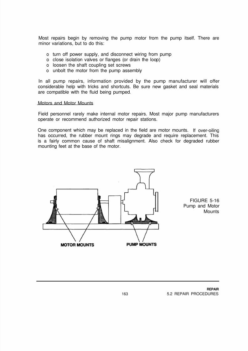
8/14/2019 Navy Maint. & Op of Active Solar Heating Sy
http://slidepdf.com/reader/full/navy-maint-op-of-active-solar-heating-sy 179/277
Most repairs begin by removing the pump motor from the pump itself. There areminor variations, but to do this:
o turn off power supply, and disconnect wiring from pump
o close isolation valves or flanges (or drain the loop)o loosen the shaft coupling set screwso unbolt the motor from the pump assembly
In all pump repairs, information provided by the pump manufacturer will offerconsiderable help with tricks and shortcuts. Be sure new gasket and seal materialsare compatible with the fluid being pumped.
Motors and Motor Mounts
Field personnel rarely make internal motor repairs. Most major pump manufacturersoperate or recommend authorized motor repair stations.
One component which may be replaced in the field are motor mounts. If over-oilinghas occurred, the rubber mount rings may degrade and require replacement. Thisis a fairly common cause of shaft misalignment. Also check for degraded rubbermounting feet at the base of the motor.
FIGURE 5-16Pump and Motor
Mounts
163
REPAIR
5.2 REPAIR PROCEDURES

8/14/2019 Navy Maint. & Op of Active Solar Heating Sy
http://slidepdf.com/reader/full/navy-maint-op-of-active-solar-heating-sy 180/277
To replace the mounts, remove the motor from the pump shaft coupling. Checkboth front and rear motor mounts. Inspect the coupling, seals and bearings forsigns of wear or leakage while the motor is off the pump. Remove or disassemblethe motor mount brackets, remove and replace the old rubber rings, and reassemblethe unit (Figure 5-16).
Couplings
If the coupling is broken, completely replace it. Do not attempt to repair or onlypartially replace broken couplings. Try to determine why the coupling broke. Pumpmisalignment is a frequent cause.
Bearings
To reach either sleeve or ball bearings, loosen the coupling and remove the motor.Depending on the pump, it may be necessary to remove a complete assemblycontaining the bearings from the pump volute or motor.
Many bearing assemblies or cartridges can be completely replaced. This isgenerally the best method. Consult the manufacturer’s service information forcomplete instructions, since special tools or materials may be required.
When repairing sleeve bearings with oil wicks, replace the wicking, rather thanreuse the old ones.
FIGURE 5-17BearingsLubricated by Oil
REPAIR
5.2 REPAIR PROCEDURES 164

8/14/2019 Navy Maint. & Op of Active Solar Heating Sy
http://slidepdf.com/reader/full/navy-maint-op-of-active-solar-heating-sy 181/277
After replacing or repairing bearings, be sure to replace the lubricating oil or grease.Use exactly the same material the manufacturer recommends.
Add oil to sleeve bearings very slowly. When you see it coming from the overflow
hole, or the indicator cup is full, enough has been added (Figure 5-17).
Ball bearings are greased, rather than oiled. The entire assembly of those that arepermanently lubricated must be replaced when worn out.
FIGURE 5-18Bearing Lubricated
by Grease
If grease can be added, remove the relief or drain plug, and add grease with agrease gun on the fill (“zerk”) fitting (Figure 5-18). Keep filling until all the old, dirtygrease has been pushed out of the plug. The motor can be run during filling tomake it easier, as long as the pump is not assembled and being run without liquid.
CAUTION
Do not attempt to add grease without removing the relief plug.
Leaving the plug in will cause the beatings to be packed solidly. Thismay cause overheating and bearing failure.
165
REPAIR
5.2 REPAIR PROCEDURES

8/14/2019 Navy Maint. & Op of Active Solar Heating Sy
http://slidepdf.com/reader/full/navy-maint-op-of-active-solar-heating-sy 182/277
Seals
Be sure the new seal material is compatible with the fluid being pumped.
Packing-type seals are normally replaced when their leakage becomes excessive.
(More than two or three drops per day.) Place a sheet of clean paper under the sealto check this.
Remove the packing gland from the shaft. After pulling off the packing rings, inspectand clean the shaft. Follow the manufacturer’s procedures to install the new rings(Figure 5-1 9).
CAUTION
Pumps with packing-type seals should not be used with solar fluids.
FIGURE 5-19Packing-Type Seals
When the pump is first started, fluid should run freely from the packing. Tighten thepacking gland bolts one-half turn at a time so the tightening is uniform. Tighten until
the leakage is close to the manufacturer’s recommendation.
When replacing mechanical seals, remove the impeller from the shaft. After pullingoff the old seal, inspect and clean the shaft. Follow the manufacturer’s proceduresfor installing the new seal and facing surfaces, if used. Be sure to compress thespring adequately when replacing the impeller (Figure 5-20).
REPAIR
5.2 REPAIR PROCEDURES 166

8/14/2019 Navy Maint. & Op of Active Solar Heating Sy
http://slidepdf.com/reader/full/navy-maint-op-of-active-solar-heating-sy 183/277
lmpellers
FIGURE 5-20Mechanical Seals
Impellers are always replaced, rather than repaired. The only exception to this iswhen impeller vanes are being “shaved” to reduce pump performance. Aftershaving, the impeller must be rebalanced, to avoid pump damage.
Volutes (Pump Bodies)
Cracks in the volute normally result in replacement. It may be possible to braze orweld these, but it is rarely worth the effort.
Whenever the volute is pulled apart for any pump repair, the gasket between thevolute halves, or the volute and the bearing assembly, should be replaced. If oldcomponents are simply being reassembled, the old gasket can be used. However,it is better to scrape out all the old material, and use a new gasket.
167
REPAIR
5.2 REPAIR PROCEDURES

8/14/2019 Navy Maint. & Op of Active Solar Heating Sy
http://slidepdf.com/reader/full/navy-maint-op-of-active-solar-heating-sy 184/277

8/14/2019 Navy Maint. & Op of Active Solar Heating Sy
http://slidepdf.com/reader/full/navy-maint-op-of-active-solar-heating-sy 185/277
The ceramic shaft used on many of these pumps can break. Sometimes the breakcannot be seen, even after tearing down the pump. Sometimes the connection tothe impeller is loose. If the impeller can be turned while the rotor is held still, theassembly must be replaced.
Bell and Gossett and Grundfos Pumps
Bell and Gossett series SLC and most Grundfos series U pumps have a removableplug at the rear of the motor. With the power off, unscrew the plug, and use ascrewdriver to manually turn and free the motor shaft.
FIGURE 5-22
Grundfos Pump ShaftPlug
Courtesy of Grundfos Pumps Corp.
Once the impeller is freed, it will usually stay unstuck if the pump is run occasionally.
169
REPAIR
5.2 REPAIR PROCEDURES

8/14/2019 Navy Maint. & Op of Active Solar Heating Sy
http://slidepdf.com/reader/full/navy-maint-op-of-active-solar-heating-sy 186/277
Taco
If the pump has not run for a long period of time, the impeller may be stuck. Theammeter will indicate about twice the normal amperage. Try rapping the pump body(gently!) with a hammer handle or a screwdriver handle while the power is on.
Taco 006 to 0010 series pumps feature a removable cartridge. This cartridgecontains the rotor, the shaft and the impeller in a waterproof cartridge. If any ofthese parts are defective, the entire cartridge is replaced.
FIGURE 5-23Disassembling Taco
Pumps
Close the isolation valves or flanges. If the pump has none, drain the system.Remove the four bolts holding the volute onto the “can” (the motor housing). Some
fluid will be in the cartridge. Disassemble the pump.
Before replacing the cartridge, hold the “can” upright and drop the old cartridge backin. Reapply power to the pump. (Watch out for flying fluid!) If the cartridge spinsfreely, inspect the inside of the volute for foreign matter or an improper castingwhich impeded normal impeller movement.
After repairing a pump, follow the procedures in Section 3.1.4 to confirm that thepump is operating properly.
REPAIR
5.2 REPAIR PROCEDURES 170

8/14/2019 Navy Maint. & Op of Active Solar Heating Sy
http://slidepdf.com/reader/full/navy-maint-op-of-active-solar-heating-sy 187/277

8/14/2019 Navy Maint. & Op of Active Solar Heating Sy
http://slidepdf.com/reader/full/navy-maint-op-of-active-solar-heating-sy 188/277
Isolate and drain the water side of the heat exchanger. Turn off the solar control, toprevent the circulation of hot solar fluid.
Connect two hoses to the water inlet and outlet of the heat exchanger. Connect onehose to the outlet of a small acid pump. (Little Giant Model 2E-NVDR isappropriate.) Connect a third hose to the inlet of the acid pump.
As you might expect, even dilute solutions of descaling acid can injureeyes and skin. Follow reasonable safety practices, including eyeprotection and rubber gloves. Keep pure and diluted mixtures out ofthe reach of children and animals. Be sure to flush descaled pipingand heat exchangers with plenty of fresh water before returning themto service.
Follow the manufacturer’s instructions to mix the descaling acid with water.Generally, solutions should be a maximum of 7% by volume. Make enough to fillthe water passageways and still have at least two inches left in the bottom of abucket.
FIGURE 5-24Descaling a HeatExchanger
REPAIR
5.2 REPAIR PROCEDURES 172

8/14/2019 Navy Maint. & Op of Active Solar Heating Sy
http://slidepdf.com/reader/full/navy-maint-op-of-active-solar-heating-sy 189/277
Drop the two unused hose ends below the surface of the acid. Turn on the pump,and allow the dilute acid to circulate through the heat exchanger for 15 to 30minutes. The time interval depends on the severity of scaling.
Turn off the pump, and allow the acid to drain out of the heat exchanger as much aspossible. Hold up the acid pump to allow it and the hoses to drain. Disconnect thepump from the hose leading into the heat exchanger.
Dispose of the used acid properly. If it is phosphoric acid, such as Scalestrip, it isbiodegradable and can be flushed down a toilet. Reflush the toilet several times toclear the acid from traps. If the acid is not biodegradable, dispose of it inaccordance with local requirements.
Connect the heat exchanger inlet hose to the fresh water supply. Flush the heatexchanger for at least five minutes. Once every trace of acid has been purged out,disconnect the hoses. Repipe the heat exchanger, and purge the air from it.
Rinse out both the acid bucket and hoses. Pump fresh water though the acid pumpbriefly and drain it before returning it to storage. Dispose of the used acid-water
mixture in accordance with local requirements.
Bonnets
Most solar heat exchanger bonnets are bronze or cast iron. Cracks in the metal cansometimes be repaired by brazing or welding. Leaks in the gasket usually requirereplacing the gasket. Since the fluid against the gasket is water, no specialmaterials are required.
Corrosion or cracks at the inlet or outlet ports of the bonnet usually indicate theneed for a replacement bonnet.
The bonnet and associated piping should be adequately and completely insulatedafter repairs are made.
Tubes and Bundles
Broken, corroded or burst tubes in coil-in-tank or tube-in-tube heat exchangerscannot be repaired. Tube-in-tube heat exchangers must be replaced. Most coil-in-
tank heat exchangers are not removable, so the entire tank must be replaced.
Brass or copper tubes in shell and tube heat exchangers can be repaired byplugging leaking tubes. Determine the internal diameter of the tubes. Have one
inch long plugs machined from brass or bronze 0.004” smaller than the tubes’ i.d.. Afive degree taper over one-half inch of the plug aids insertion.
173
REPAIR
5.2 REPAIR PROCEDURES

8/14/2019 Navy Maint. & Op of Active Solar Heating Sy
http://slidepdf.com/reader/full/navy-maint-op-of-active-solar-heating-sy 190/277
8/14/2019 Navy Maint. & Op of Active Solar Heating Sy
http://slidepdf.com/reader/full/navy-maint-op-of-active-solar-heating-sy 191/277

8/14/2019 Navy Maint. & Op of Active Solar Heating Sy
http://slidepdf.com/reader/full/navy-maint-op-of-active-solar-heating-sy 192/277
CAUTION
Oil-filled loops must never be flushed with water. Water is a
contaminant that can never be completely removed.
Reinhibiting Glycols
Reinhibiting glycol-based fluid is usually only practical when the system has over250 gallons of fluid in the collector loop. Reinhibiting requires professional analysisof the current condition of the fluid, and careful determination of the amount ofinhibitor to add to the fluid.
Depending on the inhibitor being used, it may be possible to add inhibitor directlyinto the system with a charging pump. In other cases, it may be necessary to drainout five or ten gallons of fluid from the system, mix this with inhibitor, and return thefluid to the loop. In either case, it will be necessary to recharge the system,following the instructions near the end of this subsection.
Some inhibitors, such as dipotassium phosphate, do not dissolve in glycol. Theymust be mixed with pure water, then introduced into the system, or into the rest ofthe fluid.
CAUTION
Glyco / wa t e r m i x t u r e s m u s t i n c l u d e i n h i b i t o r s t o r e t a r dcorrosion. Without proper inhibitors, these fluids rapidly becomecorrosive and damage the piping systems.
Draining and Flushing Glycol and Drainback System Collector Loops
Ideally, a drain port is in place at the lowest point of the system. Open and drain the
used glycol or water.
Small amounts of glycol trapped in low points of the loop that are in the flow can beleft undrained. However, fluid in “dead legs,” such as expansion tanks, must bedrained out. This may require cutting into the piping or unthreading joints, but itmust be done to avoid contaminating the new fluid.
REPAIR
5.2 REPAIR PROCEDURES 176

8/14/2019 Navy Maint. & Op of Active Solar Heating Sy
http://slidepdf.com/reader/full/navy-maint-op-of-active-solar-heating-sy 193/277
Install drain plugs as you repair the piping. Use teflon-based thread sealants.
Dispose of used glycol properly, according to local requirements. Consider reusingnon-toxic glycol (propylene glycol) for less critical applications, such as freezeprotection for drain traps.
If a fill/drain assembly similar to the one in Figure 5-26 is not part of the system,install one. It can be placed in any part of the loop which contains the flow of all thefluid, but an ideal spot is between the system low point and the return line comingfrom the collectors.
FIGURE 5-26Fill/Drain Assembly(using check valve)
Normally a check valve is used, as shown. A gate or ball valve can be usedinstead, but only if a working check valve is somewhere else in the loop. Having
two check valves in the loop is acceptable, since one can back up the other.
Make sure the seals and seat of the valves used are compatible with the glycol.Use a teflon-based thread sealant.
Hook up a hose to a cold water line, and connect this to the “fill” fitting downstreamof the check valve. The arrow on the check valve will point to this fitting. Connect
another hose to the “drain” fitting, and run it over to a suitable drain. Use approvedmethods to collect and dispose of used glycol solution.
177
REPAIR
5.2 REPAIR PROCEDURES
8/14/2019 Navy Maint. & Op of Active Solar Heating Sy
http://slidepdf.com/reader/full/navy-maint-op-of-active-solar-heating-sy 194/277
Normally city pressure has adequate flow and pressure to flush out the system.Occasionally, a booster pump is needed in the “fill” line, to push the water to the topof the system. If possible, flush the loop on a cloudy day to avoid thermal shock ofthe collectors.
Flush the system with city water until the fluid coming from the “drain” fitting is dear.Make sure the water is moving through all parts of the loop. On a sunny day, all thecollectors should be at the same (fairly cool) temperature.
Turn off the water, disconnect the fill hose, and allow the system to drain. Drain outany dead legs. Small amounts of “hung-up” water in the loop can be flushed outduring recharging. Dispose of used glycol properly, according to local regulations.
Automatic Water Make-Up
If glycol-filled loops are equipped with automatic water make-up, dose gate valves,if possible, and tag them so they will remain closed.
Draining and Flushing Oil Loops
In many cases, foreign matter and small amounts of water can be filtered out of theoil without draining it all out. Use a hydraulic fluid filter on a charging system asshown in Figure 5-27.
If it is necessary to drain the system, a drain port should be in place at the lowestpoint of the system. Open and drain the used oil.
Small amounts of oil hung up in parts of the loop that are in the flow can be left
undrained. However, fluid in “dead legs,” such as expansion tanks, must be drainedout. This may require cutting into the piping or unthreading joints, but it must bedone to avoid contaminating the new fluid.
WARNING!
Oils will burn when exposed to soldering torch flames. Always drainthe system before unsoldering joints! Before heating the joints,mechanically open the loop, to allow fluid vapors to escape. As the
joint comes apart, be prepared for a brief flare. Keep a fireextinguisher with you- not out in the truck!
REPAIR
5.2 REPAIR PROCEDURES 178

8/14/2019 Navy Maint. & Op of Active Solar Heating Sy
http://slidepdf.com/reader/full/navy-maint-op-of-active-solar-heating-sy 195/277
Install drain plugs as you repair the piping. Use an appropriate thread sealant forthe fluid being used (see Appendix E).
Dispose of the used oil properly, according to local requirements.
If a fill/drain assembly similar to the one in Figure 5-26 is not part of the system,install one. It can be placed in any part of the loop which contains the flow of all thefluid, but an ideal spot is between the system low point and the return line comingfrom the collectors.
CHECK VALVE
FIGURE 5-27Fill/Drain Assembly
with Charging Pumpand Filter
Normally a check valve is used, as shown. A gate or ball valve can be usedinstead, but only if a working check valve is somewhere else in the loop. Havingtwo check valves in the loop is acceptable, since one can back up the other.
Make sure the seals and seat of the valves used are compatible with the solar fluid.Use an appropriate thread sealant.
Flush the system with a cleaning solution recommended by the oil manufacturer, or
with new oil. This process is identical to charging a system, described below,except that the cleaning solution is drained afterward. Always handle and dispose ofthe cleaning solution property, in accordance with local regulation.
179
REPAIR
5.2 REPAIR PROCEDURES

8/14/2019 Navy Maint. & Op of Active Solar Heating Sy
http://slidepdf.com/reader/full/navy-maint-op-of-active-solar-heating-sy 196/277
CAUTION
Oil-filled loops must never be flushed with water. Water is acontaminant that can never be completely removed.
Flush the system until the fluid coming from the “drain” fitting is clean. Make surethe fluid is moving through all parts of the loop. On a sunny day, all the collectorsshould be at the same temperature. Their temperature will rise slightly throughoutthe process.
Refilling (Recharging) Glycol or Oil Loops
Before recharging the system, make sure the expansion tank capacity is adequatefor the system and fluid. This is especially important if the system has a history of
relief valve blow-off. Information on expansion tank sizing can be found in Diamondreference 1, in the bibliography.
It may be necessary to adjust the air pressure of diaphragm-type expansion tanksbefore filling the system. The correct air pressure is listed in Table 5-4.
Before introducing a new fluid, pressure test the piping system with compressed air.Use air rather than water to prevent damage to pipe insulation or buildingcomponents if leaks appear. Also, water must never be introduced into an oil loop.
Test at 75 PSI for a period of two to three hours. If pressure relief valves or othercomponents cannot withstand this pressure, isolate them or remove them from the
system. A lower test pressure can be used for a longer period of time, but it is notas good a test.
During the test, the pressure will fluctuate slightly (5 to 10 PSI) as the system heatsup and cools down. Leaks can be found by spraying or brushing a liquid soap andwater solution on joints and looking for bubbles. Commercial leak detection fluidscan be used instead.
If there is any doubt about the system leaking, continue the test overnight.
After the test is complete, let the air out of the system.
REPAIR
5.2 REPAIR PROCEDURES 180
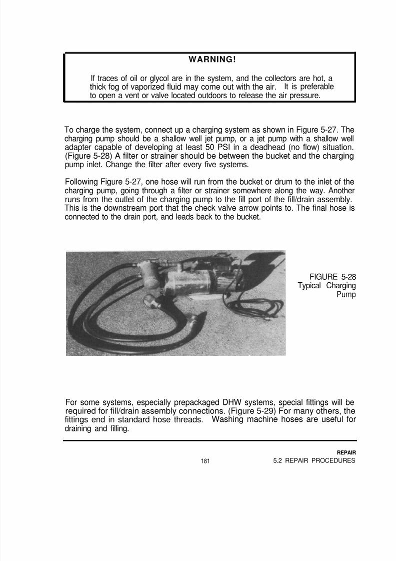
8/14/2019 Navy Maint. & Op of Active Solar Heating Sy
http://slidepdf.com/reader/full/navy-maint-op-of-active-solar-heating-sy 197/277

8/14/2019 Navy Maint. & Op of Active Solar Heating Sy
http://slidepdf.com/reader/full/navy-maint-op-of-active-solar-heating-sy 198/277
FIGURE 5-29Special Fill/Drain
Assembly Fittings
The fluid in the bucket is pulled through the charging pump and into the system.The check valve forces the fluid to move up the feed line to the collectors, upthrough the collectors, back down the return line and back into the bucket (The
same way boiler/baseboard loops are initially filled).
If a gate ball valve is used instead of a check valve, it must be closed during thecharging process.
The drain port hose is submerged in the fluid to make it easy to see any air bubblescoming out of the system.brakes.
This is similar to the process of bleeding automobile
Pour enough fluid into the bucket to fill it to within about two inches from the top ofthe bucket. Make sure all vents are closed, and turn on the charging pump. Very
quickly, air will come out the drain hose (Figure 5-30).
FIGURE 5-30Air Coming From theDrain Hose
REPAIR
5.2 REPAIR PROCEDURES 182

8/14/2019 Navy Maint. & Op of Active Solar Heating Sy
http://slidepdf.com/reader/full/navy-maint-op-of-active-solar-heating-sy 199/277

8/14/2019 Navy Maint. & Op of Active Solar Heating Sy
http://slidepdf.com/reader/full/navy-maint-op-of-active-solar-heating-sy 200/277
If the fluid level never drops, the charging pump needs priming, or is faulty. If thefluid level drops for a while, then stops, and no fluid is coming out of the dischargehose, the pump is not strong enough to push fluid to the top of the collectors.
It is a good idea to turn the solar control to the “On” position while charging, to helpthe process and purge air from the pump.
CAUTION
Make sure any other pump that will also be turned on is eitherdisconnected or filled with fluid, so it is not running while dry.
After the system has been completely filled, and all the air has been purged, noadditional bubbles will be seen. Run the charging system for at least another tenminutes. The fluid should be completely free of surface bubbles, and have no signof milkiness. A few extra minutes spent can save a return trip to recharge thesystem again.
Close the drain fitting, and allow the charging pump to build the pressure up aboutfive pounds higher than the level indicated in Table 5-5.
Once the pressure is reached, close off the fill valve, and turn off the chargingpump. Leave the pump and hoses connected.
Turn off the system control if it was turned on. Open the gate or ball valve, if onewas used in the fill/drain assembly.
After filling a glycol loop, test a small sample of the fluid. Note the pH, glycolpercentage and reserve alkalinity in the operation and maintenance record for thatsystem. Information on testing is in Section 3.1.6 in the inspection chapter.
After the system has been off for about ten minutes, briefly open the air vent oneach array of collectors. A small amount of air may be present. If more than a briefhiss of air comes out, charge the system for at least ten minutes more and check
the vents again.
If the charging process seems to be going well, but air still shows up in the system,check the suction hose and fittings on the charging pump for leaks. A jet pumpcan suck in air and still pump fluid.
REPAIR
5.2 REPAIR PROCEDURES 184

8/14/2019 Navy Maint. & Op of Active Solar Heating Sy
http://slidepdf.com/reader/full/navy-maint-op-of-active-solar-heating-sy 201/277

8/14/2019 Navy Maint. & Op of Active Solar Heating Sy
http://slidepdf.com/reader/full/navy-maint-op-of-active-solar-heating-sy 202/277
Determine the Total Fluid Volume
If original capacity is not known, use Table 5-4 and add up the fluid capacity of allthe system components and piping. If the collectors’ or heat exchanger labelsindicate fluid capacity, use that number. If not, use the number in the chart. Ignore
the fluid capacity of the expansion tank or tanks, pumps, valves and othercomponents not listed above.
Determine the Number and Size of Expansion Tank
The fill pressure table (Table 5-5) is based on expansion tanks manufactured byAmtrol, Inc. If Amtrol tanks are not used on the solar system, ask the designauthority for assistance in determining the “Amtrol equivalent” of the existingexpansion tank or tanks.
In Table 5-5, 1 x15 refers to a single #15 Extrol™ tank, 1x30 refers to a single #30tank, 15+30 means a #15 and a #30, and 2x15 means two #15 tanks. Other listingsfollow the same pattern.
Determine the System Fluid Temperature During Filling
Use a thermometer in the charging bucket to measure the temperature of the fluidwhile you are charging the system. The fill pressure chart adjusts the final fillpressure based on the fluid temperature.
Determine the System's Elevation Above Sea Level
It is necessary to make an adjustment to both the expansion tank air pressure andthe recommended system fluid pressure for the site’s elevation above sea level.
REPAIR
5.2 REPAIR PROCEDURES 186

8/14/2019 Navy Maint. & Op of Active Solar Heating Sy
http://slidepdf.com/reader/full/navy-maint-op-of-active-solar-heating-sy 203/277
TABLE 5-5: Fluid Pressure for Closed Loops
Extr o l Ma x. Fluid Pressure, PSI at Fluid Temperatures of:Tank(s) SystemModel # Volume 40°F 60°F 80°F 100°F 120°F 140°F 160°F
(Gal.)
1x152x151 x30
15+302x301 x90
30+902x90
3x90
4.79.4
12.517.225.044.556.088.0
132.0
32 33 34 35 36 37 3832 33 34 35 36 37 3833 34 35 35 37 39 4033 34 35 36 37 38 4033 34 35 36 37 39 4033 34 36 37 38 40 4233 34 35 37 38 39 4133 34 36 37 38 40 41
33 34 36 37 38 40 41
Note: This chart is based upon sea level pressure. Add one-half pound tothe fill pressure and expansion tank air pressure for every 1000 feet the siteis above sea level.
In all cases, the expansion tank air pressure, measured with no fluid pressure, is 30PSI at sea level. Add one-half PSI to the listed air pressure and system fill pressure
for every 1000 feet the system is above sea level.
5.2.7 Solar Controls,
Sensor Wires
Damaged or incorrectly routed sensor wires should be replaced with multi-strand,twisted pair wire of 18 to 22 gauge. Aluminum wire can be used for runs of up to500 feet. Above that distance, copper should be used.
Although the twisted pair design will reduce interference from electrical “noise” fromother circuits, it must still be at least two feet from other conductors, controls andloads such as motors. Where it is necessary to cross other wires, do so at a rightangle to minimize induced current (Figure 5-32).
187
REPAIR
5.2 REPAIR PROCEDURES
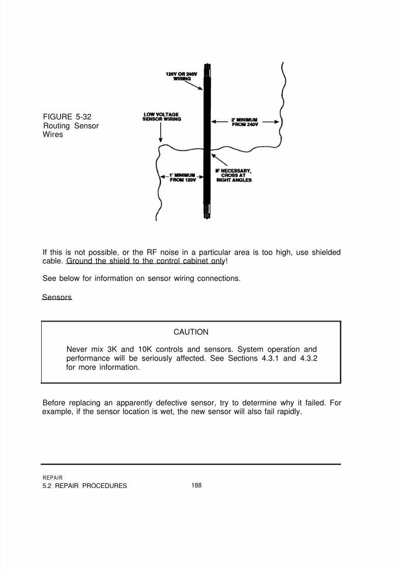
8/14/2019 Navy Maint. & Op of Active Solar Heating Sy
http://slidepdf.com/reader/full/navy-maint-op-of-active-solar-heating-sy 204/277
FIGURE 5-32Routing SensorWires
If this is not possible, or the RF noise in a particular area is too high, use shieldedcable. Ground the shield to the control cabinet only!
See below for information on sensor wiring connections.
Sensors
CAUTION
Never mix 3K and 10K controls and sensors. System operation andperformance will be seriously affected. See Sections 4.3.1 and 4.3.2for more information.
Before replacing an apparently defective sensor, try to determine why it failed. Forexample, if the sensor location is wet, the new sensor will also fail rapidly.
REPAIR
5.2 REPAIR PROCEDURES 188

8/14/2019 Navy Maint. & Op of Active Solar Heating Sy
http://slidepdf.com/reader/full/navy-maint-op-of-active-solar-heating-sy 205/277
Make sure the new sensor is in good thermal contact, and well insulated from theair. This is critical with sensors on either collectors or outside piping, but it is alsoimportant with sensors inside the building.
Connections on sensor wiring should be made with either the proper size wire nut,or a crimp-type solderless connector.
If wire nuts are used, screw the connector on the stripped wires, then fill the nutswith silicone sealant. Finally, tie a knot in the wires for strain relief.
If crimp-type connectors are preferred, either use one filled with silicone (such asthe UI™ connector by 3M), or cover the joint between the wire and the connectorafter crimping it. Soldering sensor wire connections is not necessary and is notrecommended. Use enough cable ties or insulated staples to support and protectthe wiring. Do not use regular staples, particularly from a stapling gun. These will
short out the wiring.
Check the operation of all sensors before leaving the site. Information in Section4.3.1 describes this procedure.
In some systems, one or more freeze snap switches are installed in series orparallel with the collector sensor. In others, they are part of a separate circuit.
CAUTION
Be sure the freeze snap switches used with a control are made orrecommended by the control manufacturer. Some switches open on atemperature drop, and others close on a temperature drop. The use ofthe wrong snap switch can allow the collectors to freeze.
Controls
Remember, many control problems are caused by defective or poorly installedsensors or sensor wiring. Make sure the control is really defective before replacingit.
189
REPAIR
5.2 REPAIR PROCEDURES

8/14/2019 Navy Maint. & Op of Active Solar Heating Sy
http://slidepdf.com/reader/full/navy-maint-op-of-active-solar-heating-sy 206/277

8/14/2019 Navy Maint. & Op of Active Solar Heating Sy
http://slidepdf.com/reader/full/navy-maint-op-of-active-solar-heating-sy 207/277
WARNING!
Weld ing or repai r ing epoxy or res in l in ings wi l l rap id ly
contaminate the air inside a tank to potentially deadly levels. Theseoperations should only be done by experts, both to ensure the liningwill not leak and for safety reasons.
Drain Valves
Many small tanks, of 120 gallon capacity or smaller, were originally manufacturedwith plastic drain valves. If one of these leaks, replace it with a brass tank drainvalve.
If this is not available, use a boiler drain. It may be necessary to solder together amale adapter, a two inch section of tubing and a female adapter to make an“extension” for the boiler drain.
Leaking valves on larger tanks can be replaced with identical components. Makesure you can reach the new valve conveniently, and insulate it.
Anodes
The thread sealant used by the manufacturer on storage tanks may make anoderemoval difficult, but the anode is made to be removed. Use teflon tape on the
replacement, to make future inspections and replacements easier.
In some areas, a chemical reaction takes place between contaminants in the waterand the anode rod to produce a “rotten egg” smell. Traditionally, the solution is toremove the anode from the tank.
This will result in a much shorter tank life. Install an anode made of a differentmaterial, usually aluminum. Sometimes, this will solve the problem withoutshortening tank life.
If the distance between the tank top and the ceiling prohibits installing a straight
anode rod, use a sectioned rod. This looks like links of sausage, and eliminateshaving to disconnect the tank.
191
REPAIR
5.2 REPAIR PROCEDURES

8/14/2019 Navy Maint. & Op of Active Solar Heating Sy
http://slidepdf.com/reader/full/navy-maint-op-of-active-solar-heating-sy 208/277
Dip Tubes
If the dip tubes on a tank need replacement, use a material identical to the originalone. Do not use PVC.
Remember, the purpose of dip tubes is to pick up from and deliver water to differentparts of the tank. If the dip tubes are all the same length, it defeats this purpose.
Section 4.3.12 contains information on correct dip tube lengths and placement.
Temperature and Pressure Relief Valves
Leaking or inoperative temperature and pressure (T & P) relief valves must bereplaced immediately. The usual standard valve for tanks connected to city waterpressure is 210°F/125 PSI.
WARNING!
Never use a pressure relief valve on storage tanks or otherpressurized water lines. A combination temperature and pressurerelief valve must be used for these applications. The only exceptionsare high-temperature systems. In this case, consult the systemdesigner.
After replacing the valve, comply with local plumbing requirements concerning
discharge lines. Usually, a drop line ending within 12 inches of the floor is required.However, some areas have more stringent requirements.
Be sure that any water discharged by the T & P relief valve can flow to anappropriate drain.
Insulation
Missing or inadequate tank insulation must be repaired. Another layer of tankinsulation or a new jacket may be the best way to achieve this.
If the insulation is wet, it may be allowed to dry out. However, if the mechanicalroom floor is wet on a regular basis, the tank should be elevated to protect theinsulation, as well as the tank.
REPAIR
5.2 REPAIR PROCEDURES 192

8/14/2019 Navy Maint. & Op of Active Solar Heating Sy
http://slidepdf.com/reader/full/navy-maint-op-of-active-solar-heating-sy 209/277

8/14/2019 Navy Maint. & Op of Active Solar Heating Sy
http://slidepdf.com/reader/full/navy-maint-op-of-active-solar-heating-sy 210/277
Use a wire brush to clean off any loose paint or corrosion. Use thermal epoxy tosecure the sensor to the tank.
FIGURE 5-33 Installinga Sensor on a TankWall Stud
FIGURE 5-34Clamping the HighLimit Sensor to TankOutlet
Back-Up Heating Element
Turn off all electrical power to the tank element(s). Drain the tank, unbolt the
element flange and remove the old element. If the new element includes a newgasket, scrape the old one off the tank and discard it.
If no new flange is available, remove the old element flange carefully. Install thenew element, using the new gasket, or gasket repair compound on an old one.
REPAIR
5.2 REPAIR PROCEDURES 194

8/14/2019 Navy Maint. & Op of Active Solar Heating Sy
http://slidepdf.com/reader/full/navy-maint-op-of-active-solar-heating-sy 211/277
Rewire the element, fill the tank, then reapply power. Check the current draw of thenew element to confirm it is working.
Back-Up Heating Thermostat
Turn off all electrical power to the back-up heating system, drain the tank, unbolt theold thermostat and remove it.
Bolt on the new element, rewire it, and fill the tank. Reapply power. Check thecurrent draw of the back-up element(s) while turning the thermostat up and down toconfirm it is working. Set the thermostat for the appropriate temperature.
5.3 SAMPLE REPAIR RECORD SHEET
A repair record sheet is shown on the next page. It can be copied and used directly,
or it can be retyped with modifications for particular systems.
This version has a space to describe troubleshooting activities, as well as for repairactivities. If a problem reoccurs, or a new one emerges, knowing what wassuspicious or repaired in the past can be very helpful.
After the sheet has been filled out, file it with all the other system sheets orchecklists, or with the operation and maintenance manual for that system.
195
REPAIR
5.2 REPAIR PROCEDURES

8/14/2019 Navy Maint. & Op of Active Solar Heating Sy
http://slidepdf.com/reader/full/navy-maint-op-of-active-solar-heating-sy 212/277
SYSTEM REPAIR WORKSHEET
Site: Date:
Performed by:
Original symptom or complaint:
Items inspected or troubleshot, and findings:
Items repaired or replaced:
System performance after repair/replacement:
Notes:
REPAIR
5.3 SAMPLE REPAIR RECORD SHEET 196

8/14/2019 Navy Maint. & Op of Active Solar Heating Sy
http://slidepdf.com/reader/full/navy-maint-op-of-active-solar-heating-sy 213/277
5.4 Questions for Self-study
Instructions: Choose the one answer you believe is correct. Answers to questionsare in Appendix F.
5-1 What activity is possible with tempered glass?
a) Carry it horizontallyb) Carry it verticallyc) Cut it to size at the job sited) Spray cold water on it at noon
5-2 What is the best way to weatherproof leaking collector frames?
a) Solderingb) Weldingc) Silicone sealantd) Riveting on sheet metal patches
5-3 Which of these types of hardware will quickly corrode aluminum collectorframes?
a) Galvanized steelb) Stainless steelc) Cadmium-plated steeld) Aluminum
5-4 How large should weep holes be?
a) 1/16”b) 1/8”c) 3/16”d) 1/4”
5-5 Which of these is an acceptable replacement insulation to use inside acollector?
a) Polystyreneb) Polyethylene
c) Elastomeric foamd) Polyisocyanurate foam
197
REPAIR
5.3 SAMPLE REPAIR RECORD SHEET

8/14/2019 Navy Maint. & Op of Active Solar Heating Sy
http://slidepdf.com/reader/full/navy-maint-op-of-active-solar-heating-sy 214/277
5-6 What absolutely has to be done before unsoldering collectors filled with oils orglycols?
a) Drain themb) Shade them
c) Heat them upd) Turn off the collector loop pump
5-7 Which of these is the best material to repair an absorber plate leak?
a) Silver solderb) Silver-bearing brazing alloyc) 95/5 tin/antimony solderd) 50/50 tin/lead solder
5-8 What does grounding the collector frame to the absorber do?
a) Prevents galvanic corrosionb) Protects differential thermostatc) Protects collector sensord) Protects collectors against lightning
5-9 Why is multi-strand sensor wire used?
a) Resists stretchingb) Easier to run through the roofc) Better electrical conductord) Resists RF interference
5-10 What is the minimum amount of insulation for exterior solar piping?
a) R2b) R4c) R6d) R8
5-11 One bank of collectors in an array has an outlet temperature much higher thanall the others. What should be done?
a) Nothingb) Reduce flow rate through that bankc) Increase flow rate through that bankd) Increase flow rate through the entire array
REPAIR
5.4 QUESTIONS FOR SELF-STUDY 198

8/14/2019 Navy Maint. & Op of Active Solar Heating Sy
http://slidepdf.com/reader/full/navy-maint-op-of-active-solar-heating-sy 215/277
5-12 What should be done when adding grease to a pump’s ball bearing assembly?
a) Confirm the relief plug is closed and pack the bearings tightlyb) Remove the relief plug and add grease until it just starts to come out of the
plugc) Remove the relief plug and add grease until it pushes out all the old greased) Add grease, then “top off” with oil
5-13 How can a stuck Taco 006 pump be started?
a) Remove shaft plug and turn with a screwdriverb) Turn the power on and off rapidlyc) Momentarily apply 240 volts to the motord) Tap the body with a hammer handle
5-14 Which of these is a good non-toxic descaling material?
a) Phosphoric acidb) Muriatic acidc) Sulfuric acidd) Soda ash
5-15 What is the maximum percentage of heat exchanger tubes that can be repairedby plugging without significantly affecting the heat exchanger’s performance?
a) 5%b) 10%c) 15%d) 20%
5-16 Which of these fluid’s loops can be flushed with tap water?
a) Propylene glycolb) Synthetic oilc) Silicone oild) Brayco 888
5-17 What should be the air pressure on a diaphragm-type expansion tank at sea
level ?
a) 20 PSIb) 30 PSIc) 40 PSId) 50 PSI
199
REPAIR
5.4 QUESTIONS FOR SELF-STUDY

8/14/2019 Navy Maint. & Op of Active Solar Heating Sy
http://slidepdf.com/reader/full/navy-maint-op-of-active-solar-heating-sy 216/277
5-18 What is the minimum time you should continue charging a closed-loop systemafter fluid first comes out of the drain hose?
a) 60 minutes
b) 30 minutesc) 20 minutesd) 10 minutes
5-19 What is the fluid capacity of a system with 100 feet of 1” copper tubing, 10typical 3’ by 8’ solar collectors and a 6” by 50” shell and tube heat exchanger?
a) 5.5 gallonsb) 10.4 gallonsc) 15.3 gallonsd) 20.2 gallons
5-20 What should the charging pressure of the system in 5-19 be at sea level, if ithas 2 #30 expansion tanks when the fluid temperature is 100 ºF?
a) 30 PSIb) 36 PSIc) 42 PSId) 48 PSI
5-21 What if the same system is at 4000 feet above sea level?
a) 28 PSI
b) 32 PSIc) 34 PSId) 38 PSI
5-22 Which of these is an acceptable technique when replacing sensor wires?
a) Staple them at four foot intervals to the pipe insulationb) Run them through existing electrical conduitc) Run them under the pipe insulationd) Cable tie them to the outside of the pipe insulation
REPAIR
5.4 QUESTIONS FOR SELF-STUDY 200

8/14/2019 Navy Maint. & Op of Active Solar Heating Sy
http://slidepdf.com/reader/full/navy-maint-op-of-active-solar-heating-sy 217/277
6.0PREVENTIVE MAINTENANCE
What You Will Find in This Chapter
This chapter contains information on standard preventive maintenance procedures.Some information on minor repairs is given; however, if major repairs arenecessary, use Chapter 5, Repair. If a system has not been maintained, or has notbeen operational for some time, we suggest you perform a system inspection, using
Chapter 3, and make necessary repairs, using Chapter 5, before starting a regularschedule of maintenance.
We assume you are familiar with the basic components and operation of solarsystems. If not, reading Chapter 2, Operation, will make this chapter more useful.
The information in Appendices A, B and C will be helpful in performing theoperations described in this chapter.
6.1 Maintenance Procedures
6.1.1 Solar Collectors.
Cleaning Glazings
If rain or snow do not keep the glazings clean, regular maintenance should includecleaning.
Any window cleaning product can be used, but a vinegar/water solution works justas well (10% vinegar, 90% water). Dry carefully and avoid streaking.
WARNING!
Never clean tempered glass glazings by hosing them off with waterunless they are cool. The rapid cooling and thermal contraction of theglass may cause it to shatter.
MAINTENANCE
201 6.1 MAINTENANCE PROCEDURES

8/14/2019 Navy Maint. & Op of Active Solar Heating Sy
http://slidepdf.com/reader/full/navy-maint-op-of-active-solar-heating-sy 218/277

8/14/2019 Navy Maint. & Op of Active Solar Heating Sy
http://slidepdf.com/reader/full/navy-maint-op-of-active-solar-heating-sy 219/277

8/14/2019 Navy Maint. & Op of Active Solar Heating Sy
http://slidepdf.com/reader/full/navy-maint-op-of-active-solar-heating-sy 220/277
Tightening and Sealing Frames
If the connections between frame components are sound, use silicone sealant toweatherproof them. If joints are loose and can be tightened, apply silicone to the
surfaces before tightening the collector frame.
Use stainless steel, cadmium-plated or aluminum hardware for repairing aluminumframes. Do not use galvanized hardware. Contact with zinc will corrode aluminumwithin one year.
Painting Frames
The frames of some older styles of collectors are made of mild steel. If these arerusting, remove the corroded material with a wire brush and repaint the frame.
Seals and Gaskets
If the glazing gasket is leaking, but the glazing is not broken, apply silicone sealantto suspicious spots (Figure 6-2). Make sure the collector surfaces are clean and
dry.
FIGURE 6-2Resealing awith Silicone
CollectorSealant
Leaks around the absorber headers can be repaired the same way. Make sure theheaders are not too warm. The silicone tube will list the highest applicationtemperature. Replace the piping insulation.
MAINTENANCE
6.1 MAINTENANCE PROCEDURES 204

8/14/2019 Navy Maint. & Op of Active Solar Heating Sy
http://slidepdf.com/reader/full/navy-maint-op-of-active-solar-heating-sy 221/277
Weep Holes
If the collectors have weep holes to allow moisture to escape, make sure thecollector insulation does not block them. The weep holes must be on the bottom orback of the collector, so water cannot get inside (Figure 6-3).
FIGURE 6-3Collector Weep Hole
Locations
Mounting Hardware
Tighten all loose hardware, and replace any missing parts. Look across collectorarrays to find and correct misaligned collectors (Figure 6-4). This is one or morecollectors facing in a slightly different direction. It has been compared to theappearance of butterfly wings.
MAINTENANCE
205 6.1 MAINTENANCE PROCEDURES

8/14/2019 Navy Maint. & Op of Active Solar Heating Sy
http://slidepdf.com/reader/full/navy-maint-op-of-active-solar-heating-sy 222/277
FIGURE 6-4Misaligned Collectors
If any of the connections between the mounting hardware and the building are looseor missing, repair them. Examine the other mounting points to determine how to dothis. Remember, the biggest load on these points is upward, as the wind tries topick up the collectors.
If there is any corrosion, wire brush it off and repaint. If the corrosion is a result of
two different metals being in contact (galvanic corrosion), isolate the two metalsbefore repainting. Do this with gasket material or neoprene washers.
Use silicone seal, plastic roofing cement or pitch to reseal roof leaks. Your choicewill depend on the type of roofing material and the roof/hardware connection.(Roofing cement is available in tubes for use in caulking guns.)
Lightning Protection
If lightning protection has been provided for the collector array, tighten any looseconnections, and repair or replace missing, loose or fallen lightning rods.
Tighten connections at the ground rod(s), and make sure they are still secure and ingood condition.
Make sure all collectors are under the “cone of protection” of the lightning rods,That is, within the perimeter of installed lightning rods.
MAINTENANCE
6.1 MAINTENANCE PROCEDURES 206

8/14/2019 Navy Maint. & Op of Active Solar Heating Sy
http://slidepdf.com/reader/full/navy-maint-op-of-active-solar-heating-sy 223/277
Frame Ground
Every collector with a sensor must have its frame grounded. This ground helpsprevent damage to the system control.
The typical grounding method is simple (Figure 6-5). A short piece of 12 or 14gauge copper wire is stripped at each end about two inches. One end is hoseclamped to an absorber plate header. The other end is connected to the collectorframe. The frame connection usually involves the collector mounting hardware.
FIGURE 6-5A Properly
Grounded Collector
After installing or reconnecting this ground, use an ohmmeter to make sure there isa solid electrical connection between the absorber piping and the frame. Cover the
junction between the aluminum frame and the copper wire with silicone sealant toreduce galvanic corrosion.
At the mechanical room, use the ohmmeter to confirm that the collector loop pipingis connected to ground. If it is not, hose clamp another section of copper wire to the
collector return line. Run this over to a mechanical ground, usually the same oneused for the building electrical system.
Remember that the surface of anodized or painted aluminum does not conductelectricity. Anodized aluminum may not appear to have any coating.
MAINTENANCE
207 6.1 MAINTENANCE PROCEDURES

8/14/2019 Navy Maint. & Op of Active Solar Heating Sy
http://slidepdf.com/reader/full/navy-maint-op-of-active-solar-heating-sy 224/277
Collector Flow Rates Balanced
Measure the outlet temperatures of each collector group in the array.
These temperatures should all be within 5 degrees of each other. If not, rebalancethe flow rates between collector arrays.
Balancing must be done on a sunny day when the system is operating. Open allbalancing valves fully. Reduce the flow slightly through the array with the lowestoutlet temperature. Wait three or four minutes, and recheck all the array outlettemperatures. Continue balancing and waiting until all the temperatures are withinfive degrees of each other.
NOTE
Close the balancing valves as little as possible. Reducing the flow ratethrough the collectors reduces their efficiency.
Sensor Wires and Sensors
Check sensor wires for UV degradation. They should be secure and make awatertight connection where they pass through the roof. They should not be nearsharp edges, or within 1 foot of 120V and 2 feet of 240V wiring or loads.
Make sure the connection to the sensor is still electrically sound. If the connectorsdo not appear watertight, replace them.
Make new sensor connections by twisting the wires together, then twisting on smallwire nuts. After installing the wire nuts, fill them with silicone sealant. Tie a knot inthe wires for strain relief.
Unless they are defective, the actual sensors should require no maintenance. Eachsensor must be within 1 inch of the collector housing, well insulated from the outsideair, and protected from weather and mechanical stress.
Sensor testing is described in Section 3.1.7 and replacement is described in Section5.2.7.
MAINTENANCE
6.1 MAINTENANCE PROCEDURES 208

8/14/2019 Navy Maint. & Op of Active Solar Heating Sy
http://slidepdf.com/reader/full/navy-maint-op-of-active-solar-heating-sy 225/277
6.1.2 Interior and Exterior Piping,
Insulation
Repair or replace any loose or missing pipe insulation. Exterior runs must be
covered with adequate insulation and a weatherproof jacket. This includes the shortpipes between collector headers, and the unused (and capped) headers.
Elastomeric insulations (such as Armaflex™ or Rubatex™) do not require jackets,but repaint or cover them to protect them from the sun’s UV radiation.
Fiber glass and rigid foam insulation must be jacketed. Section 2.7.8 has moreinformation on pipe insulation and jacketing materials.
Interior piping must also be insulated, but jacketing or painting is only required forappearance, color coding, or protection from inhabitants.
Use materials and techniques similar to those used originally to repair pipinginsulation. Do not use duct or electrical tape to hold the insulation together. Thismethod will fail in a few months, making the system look and perform worse thanever.
Hangers
Replace missing hangers, and tighten loose ones. Be sure galvanized hangers arenot in direct contact with copper tubing. (The galvanic corrosion resulting from thiswill “eat” the solder out of the joints.) Provide adequate cradles for the pipeinsulation to keep it from being crushed.
Leaks
Leaking soldered joints must be repaired with a high-temperature solder- not 50/50(Tin/Lead)! 95/5 (Tin/Antimony) can be used on all copper-to-copper joints. Jointsinvolving bronze should be repaired with 96/4 (Tin/Silver) solder. The use of 50/50will result in joint failure within a few months, and is a violation of plumbing code.
MAINTENANCE
209 6.1 MAINTENANCE PROCEDURES

8/14/2019 Navy Maint. & Op of Active Solar Heating Sy
http://slidepdf.com/reader/full/navy-maint-op-of-active-solar-heating-sy 226/277
WARNING!
Glycols and oils will burn when exposed to soldering torch flames.Always drain the piping before unsoldering joints! Before heating
the joints, remove the air vent to allow fluid vapors to escape. As the joint comes apart, be prepared for a brief flare. Keep a fireextinguisher with you- not out in the truck!
Threaded joints in piping filled with glycols or synthetic oils must use teflon-basedthread sealants. Teflon tape, or Rectorseal #100 are two good choices. The onlyappropriate sealant for threads exposed to silicone oils is fluorosilicone.
Brazed joints, and flared or compression fittings are all acceptable, but are rarelyused because they are less convenient than soldered or threaded joints.
Be sure to completely reinsulate the repaired piping.
CAUTION
The common practice of hydrostatic pressure testing is notacceptable for systems filled with either synthetic or silicone oils.Never put water into piping used for oils.
Bypass and Balancing Valves
Compare the configuration of flow balancing and bypass valves against the system’sOperations & Maintenance manual, or against tags or labels on valve handles.
If neither source of information exists, trace the piping to check valve positions. Usepumps and check valves for clues to flow directions. When flow direction isdetermined, tag the valves with this information or mark it on the insulation jacket forfuture reference.
Tempering Valves
Check for proper tempering valve operation by running hot water from a fixture untilthe temperature stabilizes and measuring the water temperature.
MAINTENANCE
6.1 MAINTENANCE PROCEDURES 210

8/14/2019 Navy Maint. & Op of Active Solar Heating Sy
http://slidepdf.com/reader/full/navy-maint-op-of-active-solar-heating-sy 227/277
8/14/2019 Navy Maint. & Op of Active Solar Heating Sy
http://slidepdf.com/reader/full/navy-maint-op-of-active-solar-heating-sy 228/277
On tanks without diaphragms, check the sight glass to determine the fluid level.Depending on system pressure, about half the tank volume should be air, but youshould at least be able to determine the fluid level.
6.1.3 Pumps,
Electrical Connections
Make sure all wiring, conduit and junction boxes are securely fastened. All wireconnectors and cover screws should be in place and tight. Turn shutoff switches orbreakers off and on to check them. Use an ohmmeter to confirm that the pumpmotors are properly grounded.
Piping Connections and Seals
Check all pump ports for signs of leakage or corrosion, both while the pump isrunning and when it is off. Look for leakage at the body seal on wet rotor pumpsand the shaft seal of external motor pumps.
Remember that packing seals are designed to drip slowly. If the leakage is too high,compared to the manufacturer’s recommendation, tighten the packing gland boltsone-half turn at a time so the tightening is uniform. Tighten until the leakage rate isappropriate.
If the pump has flanges, make sure the bolts are all in place and tighten any looseones. If it has isolation flanges, make sure the shutoff valves close easily and checkthem for leakage.
Support
Tighten any loose pump supports. Any rust should be removed, and the supportsrepainted.
Flow Rate
Check the flow rate of all pumping loops using a direct-reading flow meter, a flow-setter and differential pressure gauge or pressure gauges on each side of the pump.
In general, the pressure change across the pump, while it is running, is convertedfrom PSI to Feet of Water. The manufacturers published pump curve is checked todetermine the flow rate at that pressure difference. These methods are reasonably,but not completely, accurate. They are described in detail in Section 3.1.4.
MAINTENANCE
6.1 MAINTENANCE PROCEDURES 212

8/14/2019 Navy Maint. & Op of Active Solar Heating Sy
http://slidepdf.com/reader/full/navy-maint-op-of-active-solar-heating-sy 229/277
Lubrication
The motors of wet rotor pumps never require lubrication. External motor pumpsshould be checked at every inspection. If there is no way to determine lubricantlevels, a regular schedule for adding oil should be established, to avoid over-oiling
the motor.
Add oil to sleeve bearings very slowly. When you see it coming from the overflowhole, or the indicator cup is full, enough has been added (Figure 6-7).
Ball bearings are greased, rather than oiled (Figure 6-7). The entire assembly ofthose that are permanently lubricated must be replaced when worn out.
FIGURE 6-7Sleeve BearingsLubricated by Oil
(left)and Ball Bearings
Lubricated byGrease (right)
If grease can be added, remove the relief or drain plug, and add grease with agrease gun on the fill (“zerk”) fitting. Keep filling until all the old, dirty grease hasbeen pushed out the plug. The motor can be run during filling to make it easier, aslong as the pump is not assembled and being run without liquid.
Do not attempt to add grease without removing the relief plug. Leaving the plug inwill cause the bearings to be packed solidly. This may cause overheating andbearing failure.
MAINTENANCE
213 6.1 MAINTENANCE PROCEDURES

8/14/2019 Navy Maint. & Op of Active Solar Heating Sy
http://slidepdf.com/reader/full/navy-maint-op-of-active-solar-heating-sy 230/277
Shafts and Bearings
External motor pumps should be checked for shaft alignment and bearing wear. If
the shaft is out of alignment, bearings will wear quite rapidly. Listening to the pump
is one of the best ways to check and correct alignment.
Current Draw
Another excellent way to spot pump problems is by measuring the current draw ofthe pump and comparing it to the manufacturer’s specifications.
Table 3-l in Section 3.1.4 gives a general indication of the pump’s condition basedon current readings.
6.1.4 Heat Exchangers,
Piping Connections and Seals
Check all heat exchanger ports for signs of leakage or corrosion. Tighten loose boltsto stop leakage at the bonnets of shell and tube heat exchangers. If necessary,replace or repair the bonnet gasket. The fluid against this gasket should be water,so no special materials should be necessary.
Supports
Tighten up any loose connectors in heat exchanger supports. Clean off anycorrosion, prepare the surface, and repaint.
Flow Rate
Methods of checking flow rates are described in Section 3.1.4. Compare it to thespecifications in the system’s O & M manual, or check them against the rules ofthumb in Appendix B.
If potable water flow rates are significantly lower than the system specifications,scale may have built up on heat exchanger passages.
Some heat exchangers can be mechanically descaled with brushes. To do this,
drain and open the heat exchanger. Run the brush through each tube severaltimes. After brushing, flush the heat exchanger with plenty of water so small piecesof scale cannot get stuck in system components.
MAINTENANCE
6.1 MAINTENANCE PROCEDURES 214

8/14/2019 Navy Maint. & Op of Active Solar Heating Sy
http://slidepdf.com/reader/full/navy-maint-op-of-active-solar-heating-sy 231/277
In many cases, the scale cannot be removed mechanically. The heat exchangermay not be built for it, or the scale deposits may be too hard or thick. In thesecases, chemical descaling, using various types of acid is necessary. Information onthis process is in Section 5.2.5.
WARNING!
If the water being heated is potable (used for drinking, cooking orbathing), the descaling solution should not be toxic! If this is notpossible, be sure to completely flush the heat exchanger with freshwater after descaling.
Temperature Change
While the system is running, check the temperatures at the inlets and outlets of allheat exchangers. Make sure the temperatures change in the appropriate directions.The fluid entering the heat exchanger from the collectors should be higher intemperature than the fluid leaving the heat exchanger going back to the collectors.The water coming in from the storage tank should be cooler than the water goingback to the tank.
Sacrificial Anodes
If the heat exchanger has a sacrificial anode in the tube manifold, check it by
unthreading it, if it is accessible from outside the heat exchanger. If not, remove thebonnet to check it.
If the anode is gone, or nearly gone, a replacement should be obtained andinstalled.
If an exact replacement cannot be obtained, it may be possible to saw off a one ortwo inch chunk of water heater anode and place it inside the shell. Use a standardthreaded plug to close up the port in the heat exchanger. Reinsulate the heatexchanger.
Draindown Tank/Heat Exchanger
Add distilled or deionized water until the fill port overflows when the solar loop pumpis off.
Drainback systems are normally filled with distilled or deionized water.
MAINTENANCE
215 6.1 MAINTENANCE PROCEDURES

8/14/2019 Navy Maint. & Op of Active Solar Heating Sy
http://slidepdf.com/reader/full/navy-maint-op-of-active-solar-heating-sy 232/277
6.1.5 Solar Fluids.
Water
If water quality is poor, water treatment equipment may be used. The product waterfrom the treatment equipment should be checked.
Usually, water is “softened,” to remove scale-causing “hardness.” Typically, this isdone with ion-exchange softening equipment. Test for hardness with any standardwater hardness test equipment.
Sometimes iron is a problem. Standard ion-exchange softeners, specialized ironfilters, or chlorine-based treatments are used to remove iron. These can all beeasily checked with a test kit for total iron (both ferrous and ferric iron).
Glycols
Check for the recommended pressure from the system’s operation and maintenancemanual. If no such manual exists, Section 5.2.6 includes a chart of recommendedpressures.
Glycol-based fluids should be checked for glycol concentration and the condition ofthe corrosion inhibitor. If these two cannot be checked, at least check the pH(acidity/alkalinity) of the fluid.
To check glycol concentration, some manufacturers (including Dow ChemicalCompany) furnish simple test kits with simple test strips and color charts. Another
method is an optical refractometer. Both these methods only require a few drops offluid and are quite simple.
To check the condition of the corrosion inhibitor, measure either the pH or thereserve alkalinity of the fluid. Most glycol manufacturers recommend that the pHshould not drop below 7.0 and the reserve alkalinity should not drop below 8.0.Should either condition be too low, the fluid must be replaced or reinhibited.
To check the pH, use pH paper or tape, or have a laboratory analyze the fluid. Ifusing pH tape, use fairly fresh tape with a pH range from 6.0 to 8.0. Watertreatment specialists or swimming pool chemical suppliers are good sources for pH
tape. To check the reserve alkalinity, use a special test strip from the manufacturer,or have a lab check it.
MAINTENANCE
6.1 MAINTENANCE PROCEDURES 216

8/14/2019 Navy Maint. & Op of Active Solar Heating Sy
http://slidepdf.com/reader/full/navy-maint-op-of-active-solar-heating-sy 233/277
If glycol-filled loops are equipped with automatic water make-up, close gate valves,if possible, and tag them so they will remain closed.
Synthetic and Silicone Oils
Oils do not require replacement or reinhibiting. However, the fluid pressure must beadequate.
Check for the recommended pressure from the system’s operation and maintenancemanual. if no such manual exists, Section 5.2.6 includes a chart of recommendedpressures.
6.1.6 Controls.
Electrical Connections
Check all conduit and wiring connections. Make sure the system is mechanicallygrounded (to earth). Pay particular attention to the sensor wire connections. Makesure no small strands of wire from adjacent terminals touch each other. Suchcontact provides a direct short circuit which completely disrupts normal controloperation.
Mounting
Be sure the control and associated conduit is securely mounted.
Control Operation
With all sensor wires disconnected and the control switch in the “automatic” position, jumper the two terminals marked “Collector” (or “COLL,” etc.). The solar loop pump(and water loop pump, if used) should come on. (Figure 6-8)
FIGURE 6-8Checking On/Off
Operation by theJumper Method
MAINTENANCE
217 6.1 MAINTENANCE PROCEDURES

8/14/2019 Navy Maint. & Op of Active Solar Heating Sy
http://slidepdf.com/reader/full/navy-maint-op-of-active-solar-heating-sy 234/277
With the collector sensor terminals shorted, jumper the sensor terminals marked“Storage” (or “STOR,” etc.). The pump(s) should go off. (Figure 6-8)
To test the high limit function, jumper the collector sensor terminals on the control.Once the system is running, hold the leads of an appropriate resistor against the
storage sensor terminals. (Figure 6-9) The system should turn off, as the control isbeing told the storage tank is above the high limit temperature.
FIGURE 6-9Checking High
Limit Functionwith a SingleResistor
Use Table 3-3 or 3-4 to determine the right resistance to use to impersonate aparticular temperature. An abbreviated version, with resistor color codes, ispresented in Table 4-3.
MAINTENANCE
6.1 MAINTENANCE PROCEDURES 218

8/14/2019 Navy Maint. & Op of Active Solar Heating Sy
http://slidepdf.com/reader/full/navy-maint-op-of-active-solar-heating-sy 235/277
Controls: Tester Method
A more accurate method of testing differential thermostats is with a special testerdesigned for that purpose. (Figure 6-10) Normally, these units have four leads orterminals. These are connected to the collector and storage sensor terminals of the
control. The tester supplies a calibrated resistance to the two sensor inputs.
FIGURE 6-10Solar ControlTester
The dials on most testers are not very accurate. If the control has a digital display,use that instead of the numbers on the tester dial.
Sensors
To check suspicious sensors, disconnect the wires from their terminal at the control.Leave the connections intact at the sensor for the time being. Using an ohmmeterand Table 3-3 or 3-4, determine if the resistance of the sensor is appropriate for thetemperature it should be measuring.
If the control has a digital display, leave the sensor wires connected and use the
control display to check the sensors. If the displayed temperatures do not appearappropriate, disconnect the sensor wires from the control and use an ohmmeter aspreviously described.
Many digital displays indicate short or open circuits by flashing the digits on display.Again, an ohmmeter should be used on disconnected sensor wires.
MAINTENANCE
219 6.1 MAINTENANCE PROCEDURES

8/14/2019 Navy Maint. & Op of Active Solar Heating Sy
http://slidepdf.com/reader/full/navy-maint-op-of-active-solar-heating-sy 236/277
Confirm also that the sensor resistance changes as the sensor temperaturechanges. This may require warming a cool sensor in your hand, or moving a sensoroff a warm collector or tank into the cooler air.
CAUTION
Do not immerse sensors in warm or cold water. Most sensors are notwaterproof and can be damaged with water. Resistance readings ofan immersed sensor will not be correct. If water must be used toprovide temperature extremes for testing, place sensor in a watertightplastic bag.
Remember, sensor resistance goes up as temperature goes down. A temperatureincrease results in a resistance decrease. If the ohmmeter shows a direct short(zero ohms), or an open circuit (infinite ohms), check the sensor wiring as well asthe sensor itself.
Make sure sensor wiring is located at least 1 foot away from 120V, and 2 feet awayfrom 240V wiring and motors. It is very easy for a tiny electrical current to beinduced in the low voltage sensor wires. This current will make normal controloperation impossible.
6.1.7 Storage Tanks,
Drain Valves
Check that the drain valve on the storage tank opens and closes properly withoutleaking. On DHW or process heating systems, rapidly drain one gallon for every tengallons in the tank. For example, drain eight gallons from an 80 gallon tank.
Insulation
Tank insulation must be complete, dry and properly jacketed. If foam insulation hasbeen applied to the exterior, make sure it is still in good condition.
If the tank is buried, take tank-top temperature readings one hour after the end of asolar collection day and again the next morning. During that night, bypass the tank,so any temperature loss is through the tank wall and insulation, not to a load. Theovernight loss of heat on a properly insulated tank will typically result in atemperature loss of less than ten degrees Fahrenheit.
MAINTENANCE
6.1 MAINTENANCE PROCEDURES 220
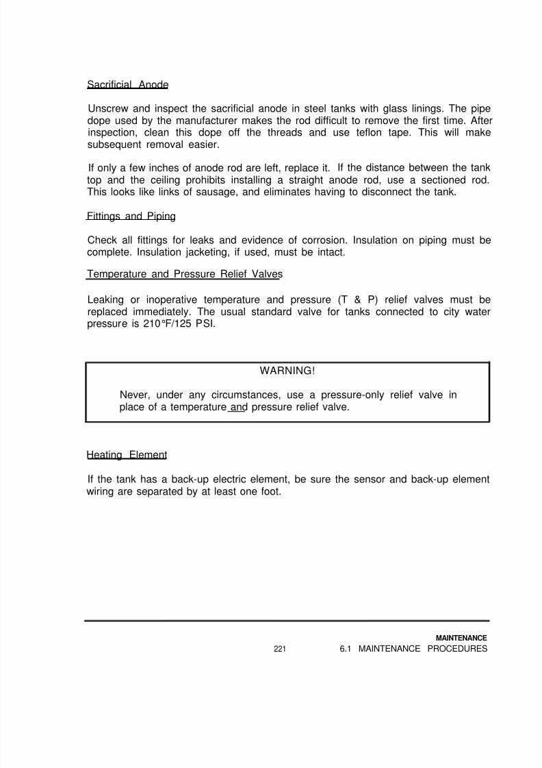
8/14/2019 Navy Maint. & Op of Active Solar Heating Sy
http://slidepdf.com/reader/full/navy-maint-op-of-active-solar-heating-sy 237/277
Sacrificial Anode
Unscrew and inspect the sacrificial anode in steel tanks with glass linings. The pipedope used by the manufacturer makes the rod difficult to remove the first time. After
inspection, clean this dope off the threads and use teflon tape. This will makesubsequent removal easier.
If only a few inches of anode rod are left, replace it. If the distance between the tanktop and the ceiling prohibits installing a straight anode rod, use a sectioned rod.This looks like links of sausage, and eliminates having to disconnect the tank.
Fittings and Piping
Check all fittings for leaks and evidence of corrosion. Insulation on piping must becomplete. Insulation jacketing, if used, must be intact.
Temperature and Pressure Relief Valves
Leaking or inoperative temperature and pressure (T & P) relief valves must bereplaced immediately. The usual standard valve for tanks connected to city waterpressure is 210°F/125 PSI.
WARNING!
Never, under any circumstances, use a pressure-only relief valve in
place of a temperature and pressure relief valve.
Heating Element
If the tank has a back-up electric element, be sure the sensor and back-up elementwiring are separated by at least one foot.
MAINTENANCE
221 6.1 MAINTENANCE PROCEDURES
8/14/2019 Navy Maint. & Op of Active Solar Heating Sy
http://slidepdf.com/reader/full/navy-maint-op-of-active-solar-heating-sy 238/277
6.2 Sample Maintenance Checklist
A maintenance checklist is shown next. It can be copied and used directly, or it canbe retyped with modifications for particular systems.
If a particular maintenance operation is performed, place a check in the columnbefore each operation. If that operation cannot be done, or is not necessary for aparticular system, make an appropriate notation in the column.
We suggest using “N.A.” for operations not applicable to a system, and an asterisk,*, if it cannot be done. Put another asterisk in the “Notes” section with anexplanation. Use the “Necessary Repairs” section near the end to describe requiredmajor repairs.
After the checklist is filled out, use it to pinpoint necessary maintenance or repairs.Then file it with all the other system inspection sheets, or with the operation and
maintenance manual for that system.
MAINTENANCE
6.2 SAMPLE CHECKLIST 222
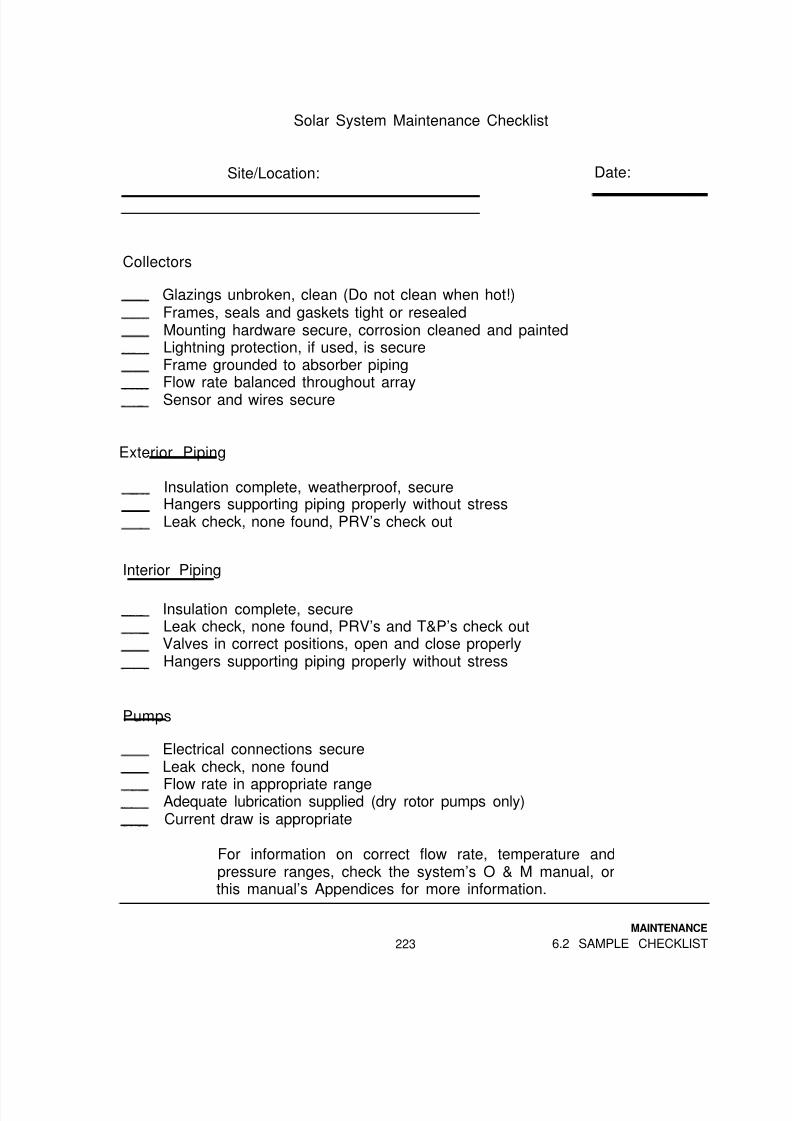
8/14/2019 Navy Maint. & Op of Active Solar Heating Sy
http://slidepdf.com/reader/full/navy-maint-op-of-active-solar-heating-sy 239/277
Solar System Maintenance Checklist
Site/Location: Date:
Collectors
Glazings unbroken, clean (Do not clean when hot!)Frames, seals and gaskets tight or resealedMounting hardware secure, corrosion cleaned and paintedLightning protection, if used, is secureFrame grounded to absorber pipingFlow rate balanced throughout arraySensor and wires secure
Exterior Piping
Insulation complete, weatherproof, secureHangers supporting piping properly without stressLeak check, none found, PRV’s check out
Interior Piping
Insulation complete, secureLeak check, none found, PRV’s and T&P’s check outValves in correct positions, open and close properlyHangers supporting piping properly without stress
Pumps
Electrical connections secureLeak check, none found
Flow rate in appropriate rangeAdequate lubrication supplied (dry rotor pumps only)Current draw is appropriate
For information on correct flow rate, temperature andpressure ranges, check the system’s O & M manual, orthis manual’s Appendices for more information.
MAINTENANCE
223 6.2 SAMPLE CHECKLIST

8/14/2019 Navy Maint. & Op of Active Solar Heating Sy
http://slidepdf.com/reader/full/navy-maint-op-of-active-solar-heating-sy 240/277
Heat Exchanger
Leak check, none foundPiping connections secureAnode in water manifold checked, replaced if necessary
Temperature differences appropriateWater level in drainback tank, if used, correct
Closed-Loop Fluid, if used
Adequate pressureGlycol pH, alkalinity and concentration acceptableAutomatic water make-up, if present, is shut off and tagged
Control
Electrical connections secureControl and conduit securely mountedOn/off differentials checkedHigh limit function checked
Sensor resistance checkedSensor wires checkedSensor wires routed correctly
Storage Tanks
Drain valve opens and closes properly10% of water drained out of tank (DHW or process heating)Leak check, none foundT & P installed, workingSensor and wiring secureHeating element thermostat, if used, checked
For information on correct flow rate, temperature and
pressure ranges, check the system’s O & M manual, orthis manual’s Appendices for more information.
MAINTENANCE
6.2 SAMPLE CHECKLIST 224

8/14/2019 Navy Maint. & Op of Active Solar Heating Sy
http://slidepdf.com/reader/full/navy-maint-op-of-active-solar-heating-sy 241/277
Paperwork
O & M manual for system on site or availableFlow Diagram and Control Sequence of Operations on site or available(see Inspection Checklist)
Service record for system on site or availableThis maintenance record filed in service record
Notes:
Necessary Repairs
Performed by:
Approved by:
MAINTENANCE
225 6.2 SAMPLE CHECKLIST
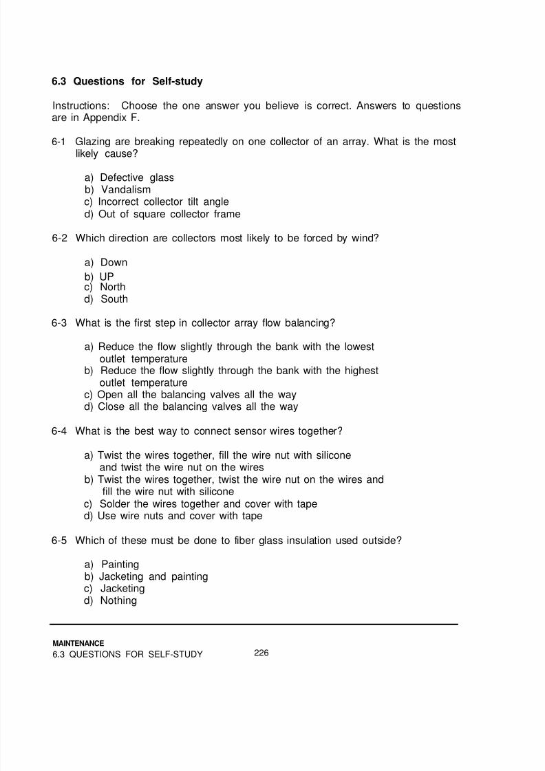
8/14/2019 Navy Maint. & Op of Active Solar Heating Sy
http://slidepdf.com/reader/full/navy-maint-op-of-active-solar-heating-sy 242/277

8/14/2019 Navy Maint. & Op of Active Solar Heating Sy
http://slidepdf.com/reader/full/navy-maint-op-of-active-solar-heating-sy 243/277
6-6 Which of these piping materials can be used in a collector loop filled withsilicone oil?
a) Standard pipe dopeb) Teflon tapec) 50/50 solderd) Fluorosilicone
6-7 Which of these can be used in a closed-loop system’s collector loop?
a) Temperature and pressure relief valveb) Draindown solar control valvec) Vacuum breakerd) Pressure relief valve
6-8 What is the correct maintenance for sleeve bearings on pumps?
a) No oil is requiredb) Oil every two to five yearsc) Oil once or twice a yeard) Oil as often as possible
6-9 Which fluid will require a sacrificial anode in the heat exchanger bonnet?
a) Silicone oilb) Ethylene glycolc) Tap water
d) Propylene glycol
6-10 Which of the following fluids is the most toxic?
a) Deionized waterb) Ethylene glycolc) Synthetic oild) Propylene glycol
6-11 What does pH indicate?
a) Acidityb) Concentrationc) Temperatured) Pressure
MAINTENANCE
227 6.3 QUESTIONS FOR SELF-STUDY

8/14/2019 Navy Maint. & Op of Active Solar Heating Sy
http://slidepdf.com/reader/full/navy-maint-op-of-active-solar-heating-sy 244/277
6-12 What is needed yearly to maintain synthetic oil?
a) Replacementb) pH adjustmentc) Rebuffering
d) Nothing
6-13 What are typical on/off differentials in degrees F for solar controls?
a) 5/20b) 20/5c) 1/5d) 1/20
6-14 Why is water periodically drained from a solar storage tank?
a) To check the back-up heating thermostat
b) To check the thermistor sensorc) To remove fallen sedimentd) To remove scale from the tank walls
MAINTENANCE
6.3 QUESTIONS FOR SELF-STUDY 228

8/14/2019 Navy Maint. & Op of Active Solar Heating Sy
http://slidepdf.com/reader/full/navy-maint-op-of-active-solar-heating-sy 245/277
BIBLIOGRAPHY
Diamond, S.C., Avery, J.G and Wood, C., Active Solar Energy System Design,Installation and Maintenance Manual, DEB-TR-86-01, Tyndall Air Force Base, FL,
Air Force Engineering and Services Center, April, 1986
Dow Chemical USA, Engineering and Operating Guide for Dowfrost and Dowtherm SR-1 Heat Transfer Fluids, 180-1190-85, Midland, Ml.
Durlak, Edward R., Preventative Maintenance: Solar Energy Thermal Systems,Techdata Sheet 84-14, Port Hueneme, CA, Naval Civil Engineering Laboratory,August, 1984.
Durlak, Edward R., Solar Energy Thermal Systems, Techdata Sheet 84-12, PortHueneme, CA, Naval Civil Engineering Laboratory, August, 1984.
Goodrich, E.W., and Carr, J.B., “Guidelines for Reliable Sensing,” Solar Engineering, May, 1981.
Grumman Energy Systems, Installation and Maintenance Instructions for Model 60FS and Model 60FST, SDMAN-3, Ronkonkoma, NY, August, 1978.
ITT Bell and Gossett, Booster Pump Service Manual, HA-105-SM, Rev. 2, MortonGrove, IL, May, 1969.
Kirby, James and Mirvis, Kenneth, Solar Energy: An Installer’s Guide to Domestic Hot Water, National Association of Solar Contractors, 1982.
Meeker, John, and Boyd, Lew, “The Great, The Good, and The Unacceptable,”Solar Age, Vol. 6, No. 10, October, 1981.
Revere Solar and Architectural Products, Inc., Revere Sun-Pride System Installation Manual, RSAP 5, Rome, NY.Solar industries, Installation and Operation Manual, Farmingdale, NJ.
Solar Thermal Systems, Daystar Solar Domestic Hot Water Systems Installation,Burlington, MA, July, 1979.
SolarVision Publications, Inc., Energy Products Specification Guide, Harrisville, NH,1984.
Tavino, Ralph R., Novan Energy Dealer Manual, Boulder, CO, 1982.
Bibliography-1 BIBLIOGRAPHY

8/14/2019 Navy Maint. & Op of Active Solar Heating Sy
http://slidepdf.com/reader/full/navy-maint-op-of-active-solar-heating-sy 246/277
Bibliography-2

8/14/2019 Navy Maint. & Op of Active Solar Heating Sy
http://slidepdf.com/reader/full/navy-maint-op-of-active-solar-heating-sy 247/277

8/14/2019 Navy Maint. & Op of Active Solar Heating Sy
http://slidepdf.com/reader/full/navy-maint-op-of-active-solar-heating-sy 248/277
FIGURE A-1 Closed-loop System
FIGURE A-2 Drainback System
APPENDIX A A-2

8/14/2019 Navy Maint. & Op of Active Solar Heating Sy
http://slidepdf.com/reader/full/navy-maint-op-of-active-solar-heating-sy 249/277

8/14/2019 Navy Maint. & Op of Active Solar Heating Sy
http://slidepdf.com/reader/full/navy-maint-op-of-active-solar-heating-sy 250/277
FIGURE A-5: Absorption Cooling System
APPENDIX A A-4

8/14/2019 Navy Maint. & Op of Active Solar Heating Sy
http://slidepdf.com/reader/full/navy-maint-op-of-active-solar-heating-sy 251/277
APPENDIX B
Rules of Thumb for Solar Systems
Introduction
The rules of thumb in this appendix are not intended to replace proper designprocedures. They are included to allow you to determine if an existing system isoperating within generally accepted ranges.
If the manufacturer’s design recommendations are available, use them, instead ofthese rules of thumb.
Flow Rates
All flow rates for collectors are in gallons per minute per gross (overall) square footof collector (GPM/sq ft). N.A. is used when that type of fluid is not used with thatsystem component.
NOTE
If a system appears to be outside of the recommended ranges, andcorrective actions on the system do not bring them back into therange, get design assistance from personnel on-base or in yourEngineering Field Division (E.F.D.).
B-1 APPENDIX B

8/14/2019 Navy Maint. & Op of Active Solar Heating Sy
http://slidepdf.com/reader/full/navy-maint-op-of-active-solar-heating-sy 252/277
TABLE B-1 : Suggested Flow Rates for Solar Applications
System
Component
GlazedFlat-PlateCollectors
Evacuated
TubeCollectors
UnglazedPoolCollectors
Closed LoopSystem StorageWater Loop
DraindownSystem StorageWater Loop
Fluid Type
Water 50/50 OilsGlycol
Gpm/sq ft Gpm/sq ft Gpm/sq ftof Collector of Collector of Collector
0.025 0.025 0.050to to to0.030 0.030 0.060
0.012 0.012
to to N.A.0.014 0.014
0.050to N.A. N.A.0.250
1.25 to 2.0times that of N.A. N.A.collector loop
1.25 to 2.0times that of N.A. N.A.collector loop
SizesPipe
Solar system piping should be sized to supply an adequate flow withoutunnecessarily large pumps. This normally means larger sizes. However, in closed
loops, the piping should be sized to provide a velocity of at least 1.5 ft/sec. to aid inair elimination, but not more than 4.0 ft/sec to avoid erosion corrosion of coppertubing and fitting walls.
The following table lists appropriate flow rate ranges for various sizes of coppertubing.
APPENDIX B B-2

8/14/2019 Navy Maint. & Op of Active Solar Heating Sy
http://slidepdf.com/reader/full/navy-maint-op-of-active-solar-heating-sy 253/277
TABLE B-2: Flow Rates for Various Copper Tubing Sizes
Tubing Size,Tubing Size,
Nominal (inches)Nominal (inches)
1/2”
3/4”
1”
1 1/4”
1 1/2”
2”
Flow Rates (gpm)
Minimum Maximum
1.5 3.5
2.5 6.5
4.0 10.0
7.0 18.5
9.5 25.0
15.0 42.0
Storage Volume
Generally, storage volume is based only on collector area, and should be between1.5 and 2.5 gallons per square foot of gross collector area.
Systems with a load which overwhelms the solar system should have storagevolumes at the lower end of the range. Systems which collect more heat than theload can use per day should have storage volumes in the upper end of the range.
Collector Tilt
Collectors should be tilted from the horizontal (not from a pitched roof!) according tothe table below. The tilt should be within 10 degrees of the listed angle. Forexample, a spaceheating system at a latitude of 35º, which should have a tilt of 50°,can have a tilt angle of 40º to 60º without a noticeable decrease in annualperformance.
B-3 APPENDIX B

8/14/2019 Navy Maint. & Op of Active Solar Heating Sy
http://slidepdf.com/reader/full/navy-maint-op-of-active-solar-heating-sy 254/277
TABLE B-3: Solar Collector Tilt Angles
Application Tilt Angle
DHWSpace HeatingDHW + Space HeatingSpace CoolingDHW + Space CoolingProcess HeatingPool Heating, summerPool Heating, all year
LatitudeLatitude + 15ºLatitude + 10ºLatitude - 15ºLatitude - 15ºLatitudeLatitude - 15ºLatitude
FIGURE B-1Collector Tilt Measuredfrom the Horizontal onTilted and LevelSurfaces
APPENDIX B B-4

8/14/2019 Navy Maint. & Op of Active Solar Heating Sy
http://slidepdf.com/reader/full/navy-maint-op-of-active-solar-heating-sy 255/277

8/14/2019 Navy Maint. & Op of Active Solar Heating Sy
http://slidepdf.com/reader/full/navy-maint-op-of-active-solar-heating-sy 256/277
FIGURE B-3Collector Orientation
The collectors should be installed within 20 degrees of a true south orientation.Generally, errors toward the west are preferable to errors toward the east.
If the collectors cannot be oriented within this range, performance will besignificantly affected.
APPENDIX B B-6

8/14/2019 Navy Maint. & Op of Active Solar Heating Sy
http://slidepdf.com/reader/full/navy-maint-op-of-active-solar-heating-sy 257/277
APPENDIX C
Tool, Material and Spare Parts Lists
Tool and Material Lists
These lists include information on the need for specific tools and materials indifferent types of operations. Not all systems or operations will require every listeditem or material, but these lists provide a starting point.
C-1 APPENDIX C

8/14/2019 Navy Maint. & Op of Active Solar Heating Sy
http://slidepdf.com/reader/full/navy-maint-op-of-active-solar-heating-sy 258/277
TABLE C-1 : Recommended Tool List
Tool Needed for:Inspection Troubleshooting Repair Maintenance
Tool Pouches X X X
Carpenter’s Hammer X X
Tape Measure X X X X
Compass X X
Inclinometer X X X
Utility Knife X X X
Screwdrivers,Phillips X X X X
Slotted X X X X
Wrenches,
Adjustable X X XOpen/Box X x X
Pipe X X
Socket X X X
Allen X X X
Caulking Gun X X
Torpedo Level X X X X
Hacksaw X
Wire Strippers X X
Needlenose Pliers X X
Gloves X X
Fire ExtinguisherX
Paint Brush X X
Electric Drill X X
Reciprocating Saw XMultimeter X X X X
Snap-AroundAmmeter X X X X
Control Testeror Resistors X X X X
Mitre Box X X
Hand Truck X
Drop Light X X X X
Channelock Pliers XVise Grips X
24’ Extension Ladder X X X X
or Stepladder X X X X
APPENDIX C C-2

8/14/2019 Navy Maint. & Op of Active Solar Heating Sy
http://slidepdf.com/reader/full/navy-maint-op-of-active-solar-heating-sy 259/277
TABLE C-1 (continued)
Tool Needed for:Inspection Troubleshooting Repair Maintenance
100’ Extension CordCharging Pump, with
Hoses and BucketSoldering Torch,with Tools
BroomCompressor orAir Bottle
Safety GlassesTin Snips
Staple GunFlashlightFirst Aid Kit100’ 1/2” Manila
RopeRubber-soled ShoesWire Brush
X X X
X
XX X
X XX X X
X
XX X XX X X
XX X X
X
X
X
XXX
XXX
XX
TABLE C-2: Recommended Material List
Material Needed for:Inspection Troubleshooting Repair Maintenance
RagsSolder,95/5 or 96/4
FluxGritclothThread SealantCopper TubingCopper Fittings
Silicone Sealantor Roof Cement
Cable TiesWire NutsElectrical Tape
X X X
XXXXXX
X XX X XX X XX X X
C-3 APPENDIX C
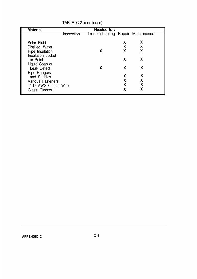
8/14/2019 Navy Maint. & Op of Active Solar Heating Sy
http://slidepdf.com/reader/full/navy-maint-op-of-active-solar-heating-sy 260/277

8/14/2019 Navy Maint. & Op of Active Solar Heating Sy
http://slidepdf.com/reader/full/navy-maint-op-of-active-solar-heating-sy 261/277
Spare Parts List
The exact number of spare parts depends on the number, size and types ofsystems. Experience has shown a range of inventory levels appropriate for eachcomponent. The following percentages are based on the total number of thatcomponent on base, not the number of systems.
An asterisk indicates that at least one of that component should be in stock at alltimes, regardless of the number of systems or components in service, as long asthat component is used on at least one system.
The minimum quantity of solar fluid is the amount required to refill the largestsystem.
TABLE C-3: Recommended Spare Parts List
Component
Collector Glazings, with Gaskets*Complete Collectors, or Absorbers*Collector Sensors*
Storage Sensors*Differential Thermostats*Wet Rotor Pumps (or Cartridges)Solar Loop Dry Rotor PumpsStorage Loop Dry Rotor PumpsTempering Valves*Pressure Relief Valves*Pressure and Temperature Relief Valves*Check Valves*Heat ExchangersExpansion Tanks*
Draindown Control Valves*Gallons of Solar Fluid*
Percentage Range
0.3% -1.0% -2.5% -
2.5% -2.5% -1.5% -1.5% -1.0% -0.5% -0.5% -1.0% -2.0% -2.5% -1.5% -
5.0% -5.0% -
5.0%3.0%
10.0%
5.0%5.0%5.0%3.0%3.0%2.0%2.0%3.0%5.0%4.0%4.0%
25.0%10.0%
C-5 APPENDIX C

8/14/2019 Navy Maint. & Op of Active Solar Heating Sy
http://slidepdf.com/reader/full/navy-maint-op-of-active-solar-heating-sy 262/277
A P P E N D I X C-6

8/14/2019 Navy Maint. & Op of Active Solar Heating Sy
http://slidepdf.com/reader/full/navy-maint-op-of-active-solar-heating-sy 263/277
APPENDIX D
Product and Supplier Information
Most of the companies listed sell their products through manufacturer’srepresentatives, distributors or both. Contact the manufacturer to find your local
supplier. These may not be the only sources of supply, but if the original source ofsupply is unavailable, and local suppliers do not carry the appropriate materials, thecompanies listed below will be able to help.
Pumps
Goulds Pumps, Inc.Seneca Falls, NY 13148(315)-568-2811Jet pumps
Grundfos Pumps Corporation2555 Clovis Ave.Clovis, CA 93613(209)-299-9741
Wet rotor, stainless steel or cast iron
ITT Bell and Gossett8200 N. AustinMorton Grove, IL 60053(312)-667-4030Dry rotor, cast iron or bronze,(also heat exchangers)
Little Giant Pump Co.3810 N. TulsaOklahoma City, OK 73112
(405)-947-2511Magnetic drive circulators and acid
pumps
Myson, Inc.P.O. Box 5025Embrey Industrial ParkFalmouth, VA 22401(703)-371-4331Wet rotor, bronze
Taco, Inc.1160 Cranston St.Cranston, RI 02920(401)-942-8000Wet rotor, cast iron or bronze(also heat exchangers)
Piping Accessories
Amtrol, Inc.1400 Division RoadW. Warwick, RI 02893(401)-884-6300
Air vents, expansion tanks, air scoops,valves, etc.
D-1 APPENDIX D

8/14/2019 Navy Maint. & Op of Active Solar Heating Sy
http://slidepdf.com/reader/full/navy-maint-op-of-active-solar-heating-sy 264/277
SISCOP.O. Box 197Riverton, NJ 08077(609)-829-8686Pressure/temperature test plugs
Sunspool Corporation439 Tasso StreetPalo Alto, CA 94301(415)-324-2022Draindown control valves
Watts Regulator Co.10 Embankment St.Lawrence, MA 01842(617)-688-1 811
Valves, vents, etc.
Controls and Sensors
Heliotrope General3733 Kenora DriveSpring Valley, CA 92077(619)-460-3930Differential thermostats, sensors,remote temperature indicators,electronic aquastat/thermostats,
control testers
Independent EnergyP.O. Box 86042 Ladd St.East Greenwich, RI 02818(800)-343-0826(401)-884-6990Differential thermostats, sensors,remote temperature indicators,electronic aquastat/thermostats,
control testers
Pyramid Controls421-16 N. Buchanan CirclePacheco, CA 94553(415)-827-0160Differential thermostats, sensors,
remote temperature indicators,control testers
Rho Sigma, Subsidiary of WATSCO1800 West 4th Ave.Hialeah, FL 33010(305)-885-1911Differential thermostats, sensors, BTUmeters, control testers
Heat Exchangers
See Taco and ITT Bell and Gosset in
pumps section
Young Radiator Company2825 Four Mile RoadRacine, WI 53404(414)-639-1011Shell and tube heat exchangers
Storage Tanks
A.O. Smith Corp.P.O. Box 28Kankakee, IL 60901(815)-933-8241Glass lined, 66 to 120 gallons, up to100 gallons
Bradford-White Co.24th & Ellsworth St.
Philadelphia, PA 19146(215)-735-6250Glass lined, 65 to 120 gallons
APPENDIX D D-2

8/14/2019 Navy Maint. & Op of Active Solar Heating Sy
http://slidepdf.com/reader/full/navy-maint-op-of-active-solar-heating-sy 265/277
Ford Products Corp.Ford Products RoadValley Cottage, NY 10989(914)-358-8282Stone lined, 40 to 120 gallons, coil in
tank available
Mor-Flo Industries, Inc.18450 S. Miles Rd.Cleveland, OH 44128(216)-663-7300Glass lined, 52 to 120 gallons
Vaughn Corp.386 Elm St.Salisbury, MA 01950
(617)-462-6683Stone lined, 66 to 120 gallons, coil intank available
Solar Glazings
Rocky Mountain Solar Glass7123 Arapaho Ave.Boulder, CO 80301(303)-442-4277
Pipe and Collector Insulations
Armstrong Cork Co.PO. Box 3001Lancaster, PA 17604(717)-397-0611Elastomeric and closed-cell pipeinsulation
Celotex Corp.
P.O. Box 22602Tampa, FL 33622Foil-faced polyisocyanurate foam
CertainTeed Corp.P.O. Box 860Valley Forge, PA 19482Fiber glass pipe insulation
Solar Fluids
Dow Chemical CompanySpecialty Chemicals Dept.Midland, Ml 48674(800)-258-2436Inhibited ethylene and propylene glycols
Dow CorningSouth Saginaw Rd., Dept. 2314
Midland, Ml 48640(517)-496-5985Silicone oil
Novan Energy, Inc.1630 N. 63d St.Boulder CO 80301(3030-447-9193Inhibited propylene glycol, Brayco™synthetic oil, and small quantities ofother solar components
D-3 APPENDIX D

8/14/2019 Navy Maint. & Op of Active Solar Heating Sy
http://slidepdf.com/reader/full/navy-maint-op-of-active-solar-heating-sy 266/277
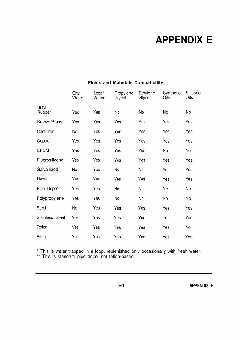
8/14/2019 Navy Maint. & Op of Active Solar Heating Sy
http://slidepdf.com/reader/full/navy-maint-op-of-active-solar-heating-sy 267/277
APPENDIX E
ButylRubber
Bronze/Brass
Cast Iron
Copper
EPDM
Fluorosilicone
Galvanized
Hydrin
Pipe Dope**
Polypropylene
Steel
Stainless Steel
Teflon
Viton
CityWater
Yes
Yes
No
Yes
Yes
Yes
No
Yes
Yes
Yes
No
Yes
Yes
Yes
Fluids and Materials Compatibility
Loop*Water
Yes
Yes
Yes
Yes
Yes
Yes
Yes
Yes
Yes
Yes
Yes
Yes
Yes
Yes
PropyleneGlycol
No
Yes
Yes
Yes
Yes
Yes
No
Yes
No
No
Yes
Yes
Yes
Yes
EthyleneGlycol
No
Yes
Yes
Yes
Yes
Yes
No
Yes
No
No
Yes
Yes
Yes
Yes
SyntheticOils
No
Yes
Yes
Yes
No
Yes
Yes
Yes
No
No
Yes
Yes
Yes
Yes
SiliconeOils
No
Yes
Yes
Yes
No
Yes
Yes
Yes
No
No
Yes
Yes
No
Yes
* This is water trapped in a loop, replenished only occasionally with fresh water.** This is standard pipe dope, not teflon-based.
E-1 APPENDIX E

8/14/2019 Navy Maint. & Op of Active Solar Heating Sy
http://slidepdf.com/reader/full/navy-maint-op-of-active-solar-heating-sy 268/277
APPENDIX E E-2

8/14/2019 Navy Maint. & Op of Active Solar Heating Sy
http://slidepdf.com/reader/full/navy-maint-op-of-active-solar-heating-sy 269/277
Chapter 2
2-1 d2-2 c2-3 a2-4 c2-5 b2-6 b2-7 b
2-8 c2-9 b2 -10 c2-11 a2-12 b2-13 d
Chapter 3
3-1 c3-2 c3-3 b3-4 a3-5 c3-6 c3-7 b3-8 b3-9 a3 - 1 0 a
3-11 b3-12 c3-13 c3-14 a3-15 a
APPENDIX F
Answers to Questions for Self-study
Chapter 4 Chapter 6
4-1 b4-2 c4-3 c4-4 a4-5 c4-6 c4-7 d
4-8 b4-9 c4-10 b4-11 a4-12 d4-13 a4-14 c4-15 b4-16 a
Chapter 5
5-1 b5-2 c5-3 a5-4 c5-5 d5-6 a5-7 b5-8 b5-9 d5-10 b
5-11 c5-12 c5-13 d5-14 a5-15 b5-16 a
6-3 a6-2 b6-1 d
6-4 b6-5 c6-6 d6-7 d
6-8 c6-9 c6-10 b6-11 a6-12 d6-13 b6-14 c
Chapter 5
(continued)
5-17 b5-18 d5-19 d5-20 b5-21 d5-22 d
F-1 APPENDIX F

8/14/2019 Navy Maint. & Op of Active Solar Heating Sy
http://slidepdf.com/reader/full/navy-maint-op-of-active-solar-heating-sy 270/277
APPENDIX F F-2

8/14/2019 Navy Maint. & Op of Active Solar Heating Sy
http://slidepdf.com/reader/full/navy-maint-op-of-active-solar-heating-sy 271/277
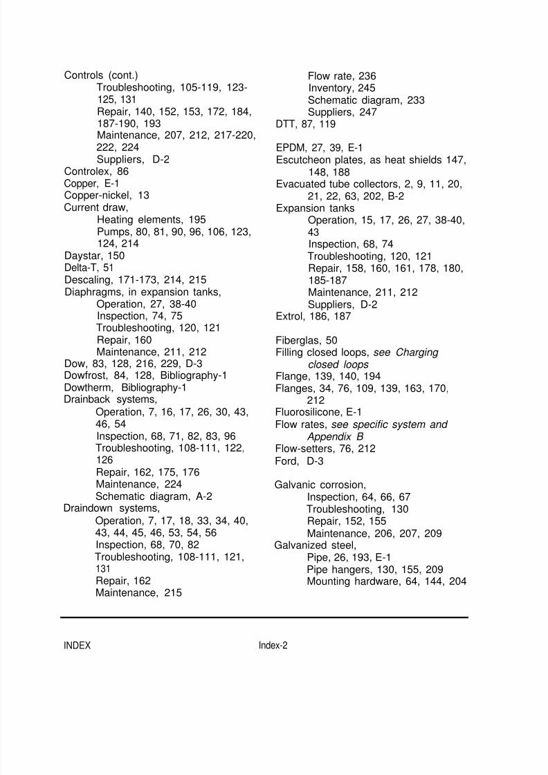
8/14/2019 Navy Maint. & Op of Active Solar Heating Sy
http://slidepdf.com/reader/full/navy-maint-op-of-active-solar-heating-sy 272/277
Controls (cont.)Troubleshooting, 105-119, 123-125, 131Repair, 140, 152, 153, 172, 184,187-190, 193
Maintenance, 207, 212, 217-220,222, 224Suppliers, D-2
Controlex, 86Copper, E-1Copper-nickel, 13Current draw,
Heating elements, 195Pumps, 80, 81, 90, 96, 106, 123,124, 214
Daystar, 150
Delta-T, 51Descaling, 171-173, 214, 215Diaphragms, in expansion tanks,
Operation, 27, 38-40Inspection, 74, 75Troubleshooting, 120, 121Repair, 160Maintenance, 211, 212
Dow, 83, 128, 216, 229, D-3Dowfrost, 84, 128, Bibliography-1Dowtherm, Bibliography-1Drainback systems,
Operation, 7, 16, 17, 26, 30, 43,46, 54Inspection, 68, 71, 82, 83, 96Troubleshooting, 108-111, 122,126Repair, 162, 175, 176Maintenance, 224Schematic diagram, A-2
Draindown systems,
Operation, 7, 17, 18, 33, 34, 40,43, 44, 45, 46, 53, 54, 56
Inspection, 68, 70, 82Troubleshooting, 108-111, 121,131Repair, 162Maintenance, 215
Flow rate, 236Inventory, 245Schematic diagram, 233Suppliers, 247
DTT, 87, 119
EPDM, 27, 39, E-1Escutcheon plates, as heat shields 147,
148, 188Evacuated tube collectors, 2, 9, 11, 20,
21, 22, 63, 202, B-2Expansion tanks
Operation, 15, 17, 26, 27, 38-40,43Inspection, 68, 74Troubleshooting, 120, 121
Repair, 158, 160, 161, 178, 180,185-187Maintenance, 211, 212Suppliers, D-2
Extrol, 186, 187
Fiberglas, 50Filling closed loops, see Charging
closed loops Flange, 139, 140, 194Flanges, 34, 76, 109, 139, 163, 170,
212Fluorosilicone, E-1Flow rates, see specific system and
Appendix B Flow-setters, 76, 212Ford, D-3
Galvanic corrosion,Inspection, 64, 66, 67Troubleshooting, 130Repair, 152, 155Maintenance, 206, 207, 209
Galvanized steel,Pipe, 26, 193, E-1Pipe hangers, 130, 155, 209Mounting hardware, 64, 144, 204
INDEX Index-2

8/14/2019 Navy Maint. & Op of Active Solar Heating Sy
http://slidepdf.com/reader/full/navy-maint-op-of-active-solar-heating-sy 273/277
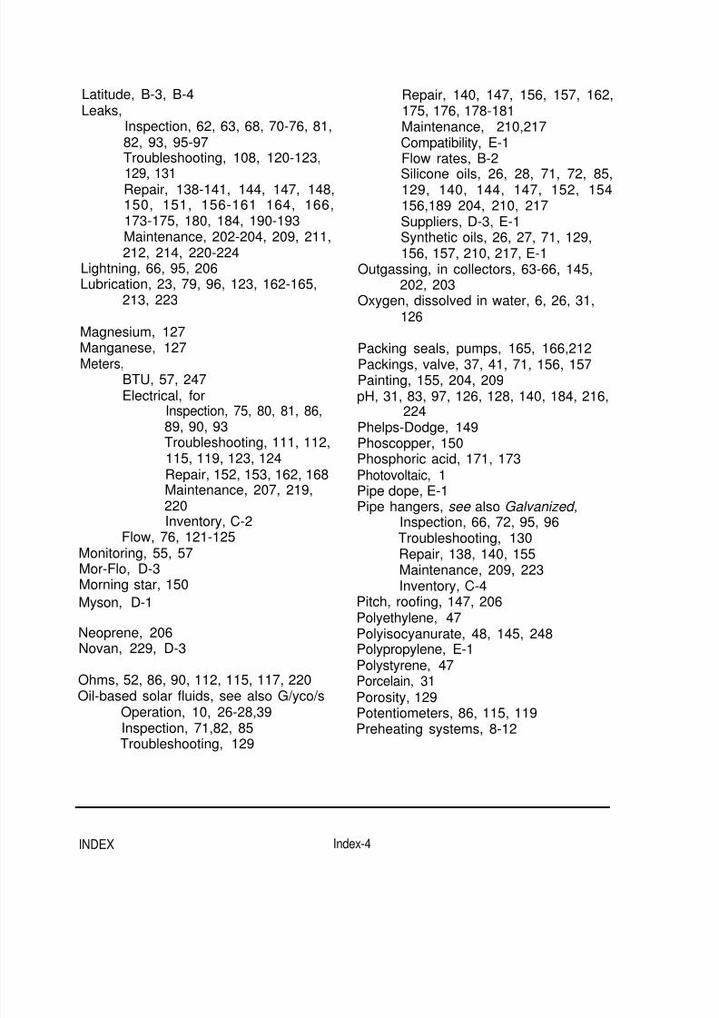
8/14/2019 Navy Maint. & Op of Active Solar Heating Sy
http://slidepdf.com/reader/full/navy-maint-op-of-active-solar-heating-sy 274/277
Latitude, B-3, B-4Leaks,
Inspection, 62, 63, 68, 70-76, 81,82, 93, 95-97Troubleshooting, 108, 120-123,
129, 131Repair, 138-141, 144, 147, 148,150, 151, 156-161 164, 166,173-175, 180, 184, 190-193Maintenance, 202-204, 209, 211,212, 214, 220-224
Lightning, 66, 95, 206Lubrication, 23, 79, 96, 123, 162-165,
213, 223
Magnesium, 127Manganese, 127Meters,
BTU, 57, 247Electrical, for
Inspection, 75, 80, 81, 86,89, 90, 93Troubleshooting, 111, 112,115, 119, 123, 124Repair, 152, 153, 162, 168Maintenance, 207, 219,220Inventory, C-2
Flow, 76, 121-125Monitoring, 55, 57Mor-Flo, D-3Morning star, 150
Myson, D-1
Neoprene, 206Novan, 229, D-3
Ohms, 52, 86, 90, 112, 115, 117, 220Oil-based solar fluids, see also G/yco/s
Operation, 10, 26-28,39Inspection, 71,82, 85Troubleshooting, 129
Repair, 140, 147, 156, 157, 162,175, 176, 178-181Maintenance, 210,217Compatibility, E-1Flow rates, B-2
Silicone oils, 26, 28, 71, 72, 85,129, 140, 144, 147, 152, 154156,189 204, 210, 217Suppliers, D-3, E-1Synthetic oils, 26, 27, 71, 129,156, 157, 210, 217, E-1
Outgassing, in collectors, 63-66, 145,202, 203
Oxygen, dissolved in water, 6, 26, 31,126
Packing seals, pumps, 165, 166,212Packings, valve, 37, 41, 71, 156, 157Painting, 155, 204, 209pH, 31, 83, 97, 126, 128, 140, 184, 216,
224Phelps-Dodge, 149Phoscopper, 150Phosphoric acid, 171, 173Photovoltaic, 1Pipe dope, E-1Pipe hangers, see also Galvanized,
Inspection, 66, 72, 95, 96
Troubleshooting, 130Repair, 138, 140, 155Maintenance, 209, 223Inventory, C-4
Pitch, roofing, 147, 206Polyethylene, 47Polyisocyanurate, 48, 145, 248Polypropylene, E-1Polystyrene, 47Porcelain, 31Porosity, 129
Potentiometers, 86, 115, 119Preheating systems, 8-12
INDEX Index-4

8/14/2019 Navy Maint. & Op of Active Solar Heating Sy
http://slidepdf.com/reader/full/navy-maint-op-of-active-solar-heating-sy 275/277
Pressure gauges,Operation, 33,55-57Inspection, 76-79,97Troubleshooting, 108-110, 121,125,132
Repair, 139, 158, 159Maintenance, 212Suppliers, D-2
Pressure reducing valves,33,40,75,129,224
Pressure relief valves,33, 36, 68,73, 192, C-5, D-2
Pressure-temperature plugs, see alsoPressure gauges,55,139
Pumps,Operation, 1, 5-17, 23-27, 34, 37,38, 43, 50-53, 56, 57Inspection, 73-80,82, 85-87,96Troubleshooting, 106, 109, 110,115, 119-125, 127, 130-132Repair, 139, 161-170, 176, 178,179,181-186Maintenance, 212-215,218, 223Flow rates, B-2Inventory, C-3Suppliers, D-1
PVC, 192
Pyramid, 87, 119, D-2Pyrometer, 67
Radio Frequency (RF) noise, 52, 188Re-inhibiting glycols, 175, 176Read-outs, on controls 89, 119Recharging closed loops, see Charging
closed loops Rectorseal, 156,210Refilling closed loops, see Charging
closed loops
Reflectors, under evacuated tubecollectors, 21,22, 63, 202Refractometer, 83, 84, 127, 128, 216,
217Reinhibiting glycols, 83, 85, 128, 217
Reservoirs, 16, 17, 30, 82, 122Resistors, 51, 87, 88, 89, 116, 117, 119,218, C-2Revere, 150, Bibliography-1Rho Sigma, 87, 119, D-2
Robertshaw, 86Rocky Mountain Solar Glass, D-3Rollbond, 149, 150Rotten egg smell, in water, 191Rubatex, 48, 71, 154, 209Rust, 204, 212
Sacrificial anodes, 32, 82, 93, 175, 215,221
Saddles, 48, C-4Scale on pipes and heat exchangers,
see Descaling and Water Scalestrip, 171, 173Schrader valves, 38, 74, 75, 121, 160,
211Screeching noises, in pumps, 111Sealants,
Operation, 27, 28Inspection, 64, 72Troubleshooting, 129Repair, 142, 144, 152, 154, 156,177,179,189, 191Maintenance, 204, 207, 208, 210
Inventory, C-3Seals,
Operation, 14, 23, 27, 33, 35, 41,42Inspection, 65, 68, 71, 75, 95Troubleshooting, 123, 129, 131Repair, 138-140, 144, 147, 154,156, 157, 161, 162, 163, 164166, 167, 168, 174, 177, 179,206,212,214,223
Seats, 27, 35, 37, 41, 42, 68, 127, 156,
162,177,179Sensors,
Operation, 6, 7Inspection, 50-55,66, 69, 70, 85-
Index-5INDEX

8/14/2019 Navy Maint. & Op of Active Solar Heating Sy
http://slidepdf.com/reader/full/navy-maint-op-of-active-solar-heating-sy 276/277
93,95, 97 B-3Sensors (cont.)
Troubleshooting, 105, 111-119,131
Repair, 138, 140, 141, 152, 153,154, 187-190, 193, 194Maintenance, 207, 208, 217-220,223,224Inventory, C-5Suppliers;. D-2
Shell and tube heat exchangers, seeHeat exchangers
Silicone oils, see Oil-based heat transfer fluids
Silver solder and brazing alloy, 26, 129,150,156, 174,209
SISCO, D-2Sleeve bearings, 164, 165,213Sludge, 83, 131Snap-switches, 54,70SolarVision, Bibliography-1Solder,
Inventory, C-5Suppliers, D-2, D-3
Strain relief, 154, 189, 208
Strainers, 110, 181Sun-Pride, 229Sunspool, 247Sunstream, 150Sunstrip, 149Sunworks, 150Swimming pools, 2,8, 12-13, 22-23, 83,
216Synthetic oils, see Oil-based heat
transfer fluids
Taco, 170, D-1, D-2
Tanks, see also Storage tanks,Cement-lined, 33Epoxy-lined, 30, 33, 191Galvanized, 33Glass-lined, 31, 32, 190, 221,D-2, D-3
Operation, 25Troubleshooting, 129, 130Repair, 147, 150, 151, 155-157,174,178,189,191Maintenance, 209, 210
Inventory, C-3Solderless connectors, 189Solenoid valves, 18, 44, 45Spool valves, 45Squeaking, in pumps 110Stainless steel, 13, E-1Staples, 90, 112, 154, 189, C-3Steel, E-1Stewart-Hall, 171Storage tanks,
Operation, 1, 6-9, 11, 12, 14-17,26-33, 36, 46, 50Inspection, 74,93, 94, 97, 101Troubleshooting, 108-111,131,132Repair, 141, 190-195Maintenance, 220,221Flow rates and volumes, B-2,
Manways, 141,190Phenolic resin-lined, 30, 33, 191Stone-lined, 30, 32, 33, 190, D-3
Teflon, 27,93, 154, 156, 177, 191, 210,221, E-1
Temperature and pressure relief valves,33, 36, 37, 74, 192, 221, 224,
C-5, D-2Tempering valves, 73, 109, 130, 210,
C-5TempTrak, 87, 119Terralite, 149Thermafin, 149Thermistors, 51, 52, 55, 69, 228Thermometers, 34, 55, 56, 67, 131,
132,139,157,158,186Thermosiphoning,
In closed loop systems, 15, 34,45, 109,130, 131Water heating systems, 18, 19
Thermostats, see Controls Toxicity, 27, 81, 171, 215Tube-in-tube heat exchangers, 28
INDEX Index-6
8/14/2019 Navy Maint. & Op of Active Solar Heating Sy
http://slidepdf.com/reader/full/navy-maint-op-of-active-solar-heating-sy 277/277
Ultraviolet radiation 48 69 71 72 73Waterproofing,
Inspection 69 71 72 95