nc code reference manual - imodela · nc code reference manual. 1 ... preparatory functions (g...
TRANSCRIPT
Thank you very much for purchasing this product. To ensure correct and safe usage with a full understanding of this product's performance, please
be sure to read through this manual completely and store it in a safe location. Unauthorized copying or transferral, in whole or in part, of this manual is prohibited. The contents of this operation manual and the specifications of this product are subject to change
without notice. The operation manual and the product have been prepared and tested as much as possible. If you
find any misprint or error, please inform us. Roland DG Corp. assumes no responsibility for any direct or indirect loss or damage which may occur
through use of this product, regardless of any failure to perform on the part of this product. Roland DG Corp. assumes no responsibility for any direct or indirect loss or damage which may
occur with respect to any article made using this product.
NC CODEREFERENCE MANUAL

1
Table of Contens
Table of Contens .........................................................................................................................1
Introduction ........................................................................................................................................3
Contents of This Document .........................................................................................................3
Chapter 1 Programming Overview ...................................................................................................5
1-1 Programming Basics .............................................................................................................6Program Format ............................................................................................................................................................................. 6Program Structure ......................................................................................................................................................................... 7
1-2 Coordinate Systems ..............................................................................................................8Machine Coordinate Systems and Workpiece Coordinate Systems ............................................................................ 8Specifying Coordinates and Distances ................................................................................................................................10
1-3 Main Word Characteristics ..................................................................................................12Preparatory Functions (G Functions) ....................................................................................................................................12Miscellaneous Functions (M Functions) ..............................................................................................................................12Feed Function (F Function) ......................................................................................................................................................12Spindle Speed Function (S Function) ...................................................................................................................................13
1-4 Feed Rate and Spindle Speed ............................................................................................14Feed Rate and Overrides ...........................................................................................................................................................14Rotation Speed and Overrides ...............................................................................................................................................14A-axis Feed Rate ...........................................................................................................................................................................14
1-5 How Values Are Interpreted ................................................................................................15Expressing Numerical Values...................................................................................................................................................15Millimeter Input and Inch Input .............................................................................................................................................15Interpretation Methods and Units of Values .....................................................................................................................16Unit of Measurement for Angles ...........................................................................................................................................16
1-6 Sample Program .................................................................................................................17
Chapter 2 Code Reference ..............................................................................................................19
2-1 Explanatory Notes ...............................................................................................................202-2 Preparatory Functions (G Functions) ..................................................................................21
G00 <Positioning> .....................................................................................................................21G01 <Linear Interpolation> ....................................................................................................22G02 and G03 <Circular Interpolation> ................................................................................................23G04 <Dwell> ................................................................................................................................26G10 <Data Setting> ...................................................................................................................27G17, G18, and G19 <Plane> ................................................................................................................................28G20 and G21 <Measurement Unit> ......................................................................................................29G28 <Reference-point Return> .............................................................................................30G39 <Corner-offset Circular Interpolation> .....................................................................31G40, G41, and G42 <Tool-diameter Offset> ..................................................................................................32G43 and G49 <Tool-length Offset> .......................................................................................................40G50 and G51 <Scaling> .............................................................................................................................41G53 <Movement in the machine coordinate system> .................................................42G54, G55, G56, G57, G58, and G59 <Select Coordinate System> ........................................................................................43G80, G81, G82, G83, G85, G86, and G89 <Fixed Cycle (Canned Cycle)> ......................................................................................44G90 and G91 <Absolute and Incremental> .......................................................................................49G92 <Coordinate System> ......................................................................................................50G98 <Initial Level Return> ......................................................................................................52G99 <Point R Level Return> ...................................................................................................52
2-3 Miscellaneous Functions (M Functions) ..............................................................................53M00 <Program Stop> ................................................................................................................53M01 <Optional Stop> ...............................................................................................................53
Table of Contens
2
http://www.rolanddg.com/
Company names and product names are trademarks or registered trademarks of their respective holders.
Copyright © 2006-2009 Roland DG Corporation
M02 <End of Program> ............................................................................................................53M03 and M05 <Spindle Motor Start/Stop> ........................................................................................54M06 <Tool Selection> ...............................................................................................................54M12 and M13 <Air Blower On/Off> .......................................................................................................55M14 and M15 <Chip Cleaner On/Off> ..................................................................................................55M16 and M17 <Light On/Off> .................................................................................................................55M30 <End of Program> ............................................................................................................55
2-4 Spindle Speed Function (S Function) .................................................................................56S <Spindle Speed> ..............................................................................................................56
2-5 Feed Function (F Function) .................................................................................................58F <Feed Rate> .......................................................................................................................58
2-6 Other Functions ..................................................................................................................60N <Sequence Number> ......................................................................................................60O <Program Number> ........................................................................................................60/ <Optional Block Skip> ....................................................................................................61% <Data Start/Data End> ...................................................................................................61EOB <End of Block> ..................................................................................................................62( ) <Comment> .......................................................................................................................62
2-7 List of Words .......................................................................................................................63Preparatory Functions (G Functions) ....................................................................................................................................63Other Functions ...........................................................................................................................................................................64
3
Introduction
Contents of This Document
This document describes the JIS (Japanese Industrial Standards) defined codes interpreted by numerically controlled machine tools (NC codes) that are supported by the machine manufactured by Roland DG Corp. About NC code which is supported by the each machine, refer to the documentation for each machine. Many of the supported codes are compliant with JIS.
This document is composed of two parts."Chapter 1 -- Programming Overview" includes "Programming Basics," "Coordinate Systems," and other sections that explain the requisite fundamentals of programming."Chapter 2 -- Code Reference" describes the functioning of each code in detail.

4
Chapter 1 Programming Overview
5
1-1 Programming Basics
Program Format
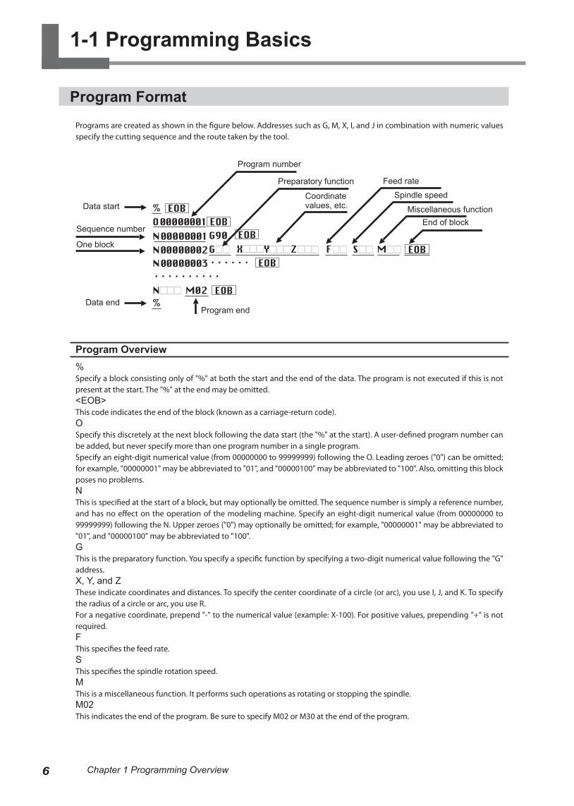
Programs are created as shown in the figure below. Addresses such as G, M, X, I, and J in combination with numeric values specify the cutting sequence and the route taken by the tool.
Program Overview%Specify a block consisting only of "%" at both the start and the end of the data. The program is not executed if this is not present at the start. The "%" at the end may be omitted. <EOB>This code indicates the end of the block (known as a carriage-return code).OSpecify this discretely at the next block following the data start (the "%" at the start). A user-defined program number can be added, but never specify more than one program number in a single program. Specify an eight-digit numerical value (from 00000000 to 99999999) following the O. Leading zeroes ("0") can be omitted; for example, "00000001" may be abbreviated to "01", and "00000100" may be abbreviated to "100". Also, omitting this block poses no problems.NThis is specified at the start of a block, but may optionally be omitted. The sequence number is simply a reference number, and has no effect on the operation of the modeling machine. Specify an eight-digit numerical value (from 00000000 to 99999999) following the N. Upper zeroes ("0") may optionally be omitted; for example, "00000001" may be abbreviated to "01", and "00000100" may be abbreviated to "100".GThis is the preparatory function. You specify a specific function by specifying a two-digit numerical value following the "G" address.X, Y, and ZThese indicate coordinates and distances. To specify the center coordinate of a circle (or arc), you use I, J, and K. To specify the radius of a circle or arc, you use R. For a negative coordinate, prepend "-" to the numerical value (example: X-100). For positive values, prepending "+" is not required.FThis specifies the feed rate.SThis specifies the spindle rotation speed.MThis is a miscellaneous function. It performs such operations as rotating or stopping the spindle.M02This indicates the end of the program. Be sure to specify M02 or M30 at the end of the program.
Data start
Sequence number
One block
Program number
Preparatory function
Coordinate values, etc.
Feed rate
Spindle speed
Miscellaneous functionEnd of block
Program endData end
6 Chapter 1 Programming Overview
Program Structure
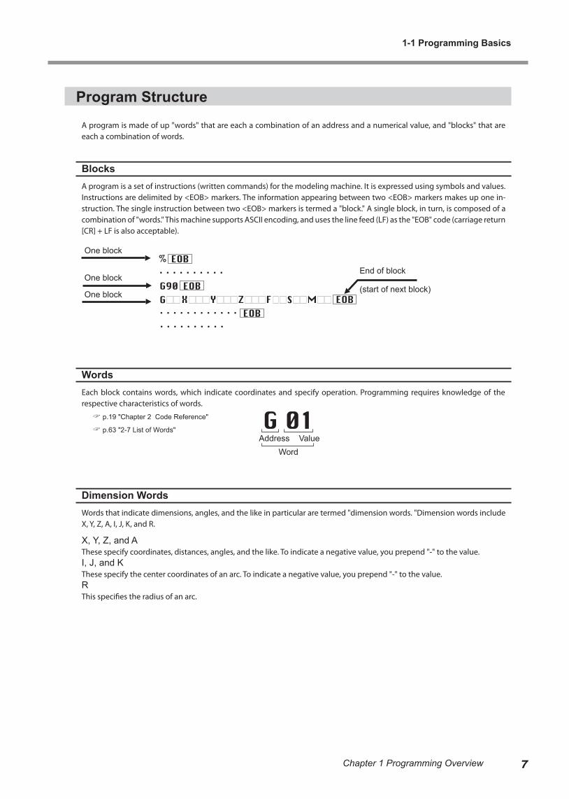
A program is made of up "words" that are each a combination of an address and a numerical value, and "blocks" that are each a combination of words.
BlocksA program is a set of instructions (written commands) for the modeling machine. It is expressed using symbols and values. Instructions are delimited by <EOB> markers. The information appearing between two <EOB> markers makes up one in-struction. The single instruction between two <EOB> markers is termed a "block." A single block, in turn, is composed of a combination of "words." This machine supports ASCII encoding, and uses the line feed (LF) as the "EOB" code (carriage return [CR] + LF is also acceptable).
WordsEach block contains words, which indicate coordinates and specify operation. Programming requires knowledge of the respective characteristics of words.
p.19 "Chapter 2 Code Reference"
p.63 "2-7 List of Words"
Dimension WordsWords that indicate dimensions, angles, and the like in particular are termed "dimension words. "Dimension words include X, Y, Z, A, I, J, K, and R.
X, Y, Z, and AThese specify coordinates, distances, angles, and the like. To indicate a negative value, you prepend "-" to the value.I, J, and KThese specify the center coordinates of an arc. To indicate a negative value, you prepend "-" to the value.RThis specifies the radius of an arc.
One block
One block
One block
End of block
(start of next block)
WordAddress Value
1-1 Programming Basics
7Chapter 1 Programming Overview

1-2 Coordinate Systems
Machine Coordinate Systems and Workpiece Coordinate Systems
Machine Coordinate SystemsThese are coordinate systems which are determined mechanically. The location of the origin in a machine coordinate system is at the highest position at the forward-left corner of the machine's range of operation for the X, Y, and Z axes, and at a specific angle determined mechanically for the A-axis. The origin for a machine coordinate system is at a location specific to the modeling machine, and cannot be changed.In actual programming, workpiece coordinate systems are used exclusively instead of machine coordinate systems.
Workpiece Coordinate SystemsThese are the coordinate systems used in programs. The location of the origin for a workpiece coordinate system can be set freely.
Setting a Workpiece Coordinate System (G54 through G59)This machine has six workpiece coordinate systems. You use G54 through G59 to specify which one to use.The location of a workpiece coordinate system is represented by an offset value from the origin of the machine coordinate system. This is called the "workpiece origin-point offset."The setting for the workpiece origin-point offset is made on the modeling machine. (It can also be set using G10).
p.27 "G10 <Data Setting>"
For information on how to make the setting, refer to the documentation for the modeling machine.
Workpiece coordinate system 1 (G54)
Workpiece origin-point offset
Machine coordinate origin
Workpiece coordinate system 4 (G57) Workpiece coordinate
system 3 (G56)
Workpiece coordinate system 2 (G55)
Workpiece coordinate system 5 (G58)
Workpiece coordinate system 6 (G59)
8 Chapter 1 Programming Overview
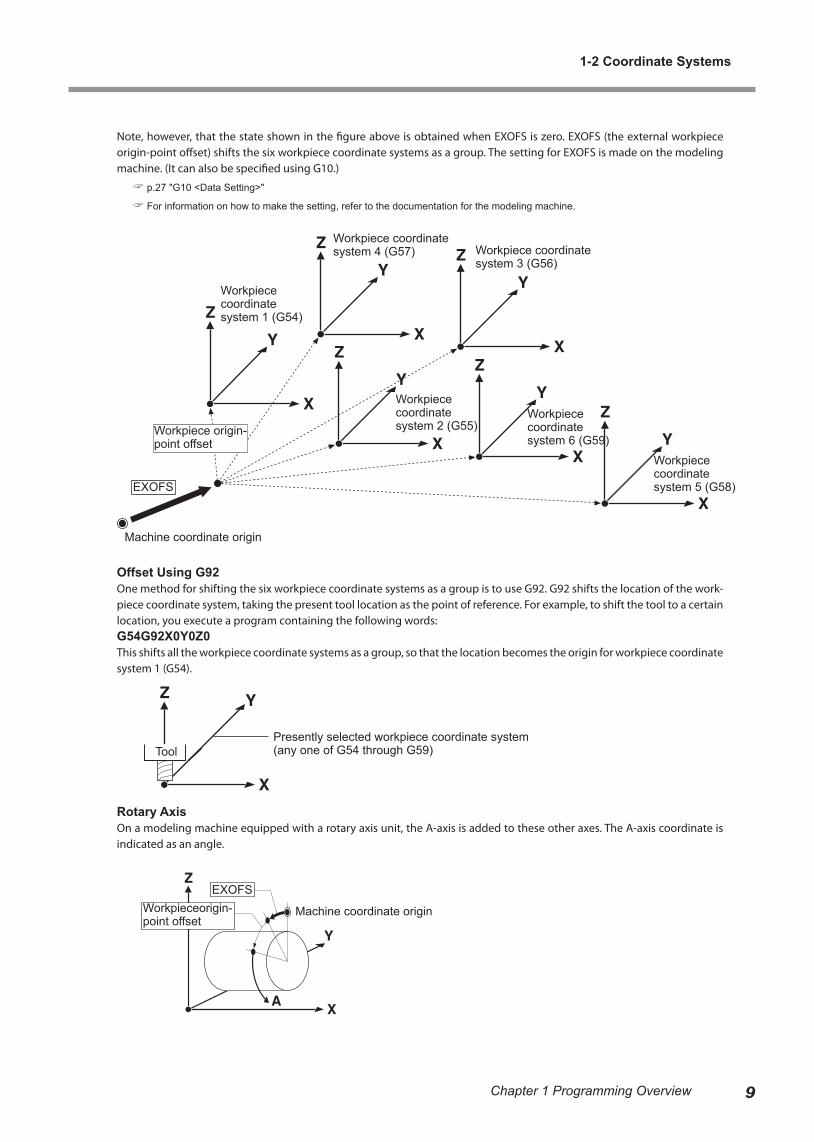
Note, however, that the state shown in the figure above is obtained when EXOFS is zero. EXOFS (the external workpiece origin-point offset) shifts the six workpiece coordinate systems as a group. The setting for EXOFS is made on the modeling machine. (It can also be specified using G10.)
p.27 "G10 <Data Setting>"
For information on how to make the setting, refer to the documentation for the modeling machine.
Offset Using G92One method for shifting the six workpiece coordinate systems as a group is to use G92. G92 shifts the location of the work-piece coordinate system, taking the present tool location as the point of reference. For example, to shift the tool to a certain location, you execute a program containing the following words:G54G92X0Y0Z0This shifts all the workpiece coordinate systems as a group, so that the location becomes the origin for workpiece coordinate system 1 (G54).
Rotary AxisOn a modeling machine equipped with a rotary axis unit, the A-axis is added to these other axes. The A-axis coordinate is indicated as an angle.
Presently selected workpiece coordinate system (any one of G54 through G59)
Workpiece coordinate system 1 (G54)
Workpiece origin-point offset
Machine coordinate origin
EXOFS
Tool
EXOFSWorkpieceorigin-point offset
Machine coordinate origin
Workpiece coordinate system 2 (G55)
Workpiece coordinate system 3 (G56)
Workpiece coordinate system 4 (G57)
Workpiece coordinate system 6 (G59)
Workpiece coordinate system 5 (G58)
1-2 Coordinate Systems
9Chapter 1 Programming Overview

Specifying Coordinates and Distances
To specify the values for coordinates and the like, you use "X x, Y y, Z z, and A a," "I cx, J cy, and K cz," or "R."
X, Y, Z, and AThese are used with positioning (G00), linear interpolation (G01), and the like. X x, Y y, Z z, and A a correspond respectively to the X-axis, Y-axis, Z-axis, and A-axis coordinates. Specifying all of them at the same time is not required. For instance, when you want to leave the Y and Z axes unchanged and move 10 millimeters along only the X axis, you would specify "G00X10.0".
I, J, and KThese specify the center coordinates of the arc when performing circular interpolation. Circular interpolation can be per-formed only on the X-Y, Z-X, and Z-Y planes. The relationship between the planes and the I cx, J cy, and K cz dimension words is as shown below.
X-Y plane = Specified using IJY-Z plane = Specified using JKZ-X plane = Specified using IK
RThis specifies the radius of the arc when performing circular interpolation.
Specified using JK
Specified using IK
Specified using IJ
X-Y plane
Y-Z planeZ-X plane
1-2 Coordinate Systems
10 Chapter 1 Programming Overview
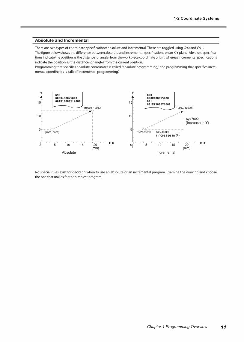
Absolute and IncrementalThere are two types of coordinate specifications: absolute and incremental. These are toggled using G90 and G91.The figure below shows the difference between absolute and incremental specifications on an X-Y plane. Absolute specifica-tions indicate the position as the distance (or angle) from the workpiece coordinate origin, whereas incremental specifications indicate the position as the distance (or angle) from the current position.Programming that specifies absolute coordinates is called "absolute programming," and programming that specifies incre-mental coordinates is called "incremental programming."
No special rules exist for deciding when to use an absolute or an incremental program. Examine the drawing and choose the one that makes for the simplest program.
Absolute Incremental
(Increase in Y)
(Increase in X)
1-2 Coordinate Systems
11Chapter 1 Programming Overview
1-3 Main Word Characteristics
Preparatory Functions (G Functions)
G codes are divided into modal and one-shot codes. A one-shot code functions only within the block where it is specified, but a modal code continues to function in subsequent blocks. Modal codes can be divided into several groups, and the functioning of one continues to remain in effect until a different word of the same group is encountered.For instance, G00 and G01 are both modal, and they belong to the same group. Accordingly, composing an instruction using only dimension words is possible, as shown below. This is a special property of G codes.
G00X15000Y15000 G00 starts to function.Z5000 G00 continues to function (identical to G00Z5000).G01Z-3000 G00 is disabled and G01 starts to function.X50000 G01 continues to function (identical to G01X50000).X15000Y30000 G01 continues to function (identical to G01X15000Y30000).
Any number of G codes of different groups can be placed within a single block. When more than one G code of the same group appears in a single block, the last G code takes effect.
p.63 "2-7 List of Words"
Miscellaneous Functions (M Functions)
An M code operates at the start of the block in which it is specified.
G00X15000Y10000M03
In this example, the spindle starts to turn, and then operation of G00 starts. Note carefully that operation does not necessarily occur in the sequence in which the words are given.
p.63 "2-7 List of Words"
Feed Function (F Function)
The feed rate is specified using an F code.
G01X15000F300000G17G03X20000Y5000J5000
When a G code or the like is present in the same block, this code functions concurrently. In this example, the G01 operation is performed at a speed of 300 mm/min. An F code continues to function in subsequent blocks, and the feed rate does not change until another F code is specified. In this example, the G03 in the second line is also performed at a feed rate of 300 mm/min.
p.63 "2-7 List of Words"
12 Chapter 1 Programming Overview
Spindle Speed Function (S Function)
The speed of rotation of the spindle is specified using S codes.
G00X15000Y10000M03S8000
When an M03, a G code, or the like is present in the same block, this code functions concurrently. In this example, the G00 operation is performed simultaneously with the spindle rotating at a speed of 8,000 rpm.
p.63 "2-7 List of Words"
1-3 Main Word Characteristics
13Chapter 1 Programming Overview
1-4 Feed Rate and Spindle Speed
Feed Rate and Overrides
The feed rate is specified using an F code, but the specified feed rate may not necessarily always be obtained.G00 (positioning) is performed at the modeling machine's highest speed, without obeying the specification of the F code. Adjusting the feed rate by means of an override is also possible.
An override is a setting made on the modeling machine. You can adjust the feed rate manually as you monitor the actual cutting. Two overrides are available: a G00 (positioning) override and an override of the feed rate specified by the F code. You specify an override as a percentage, with each respective feed rate taken to be 100%.For instance, executing a program that specifies a rate of 600 mm/min. at an override of 50% yields an actual feed rate of 300 mm/min. Note, however, that operation beyond the modeling machine's minimum or maximum feed rate is not possible. Adjusting the feed rate to a value finer than the minimum resolution is also impossible.
For more information about setting overrides, refer to the documentation for the modeling machine.
Rotation Speed and Overrides
You can also apply overrides to the spindle speed. You can adjust the speed manually as you monitor the actual cutting. For instance, executing a program that specifies a speed of 8,000 rpm at an override of 50% yields an actual speed of 4,000 rpm. Note, however, that operation beyond the modeling machine's minimum or maximum speed is not possible. Adjusting the speed to a value finer than the minimum resolution is also impossible.
For more information about setting overrides, refer to the documentation for the modeling machine.
A-axis Feed Rate
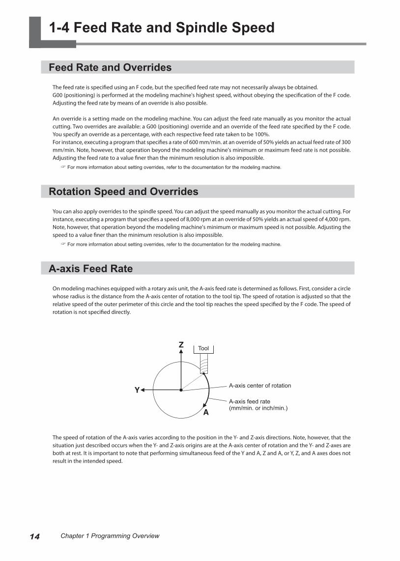
On modeling machines equipped with a rotary axis unit, the A-axis feed rate is determined as follows. First, consider a circle whose radius is the distance from the A-axis center of rotation to the tool tip. The speed of rotation is adjusted so that the relative speed of the outer perimeter of this circle and the tool tip reaches the speed specified by the F code. The speed of rotation is not specified directly.
The speed of rotation of the A-axis varies according to the position in the Y- and Z-axis directions. Note, however, that the situation just described occurs when the Y- and Z-axis origins are at the A-axis center of rotation and the Y- and Z-axes are both at rest. It is important to note that performing simultaneous feed of the Y and A, Z and A, or Y, Z, and A axes does not result in the intended speed.
Tool
A-axis feed rate (mm/min. or inch/min.)
A-axis center of rotation
14 Chapter 1 Programming Overview
1-5 How Values Are Interpreted
Expressing Numerical Values
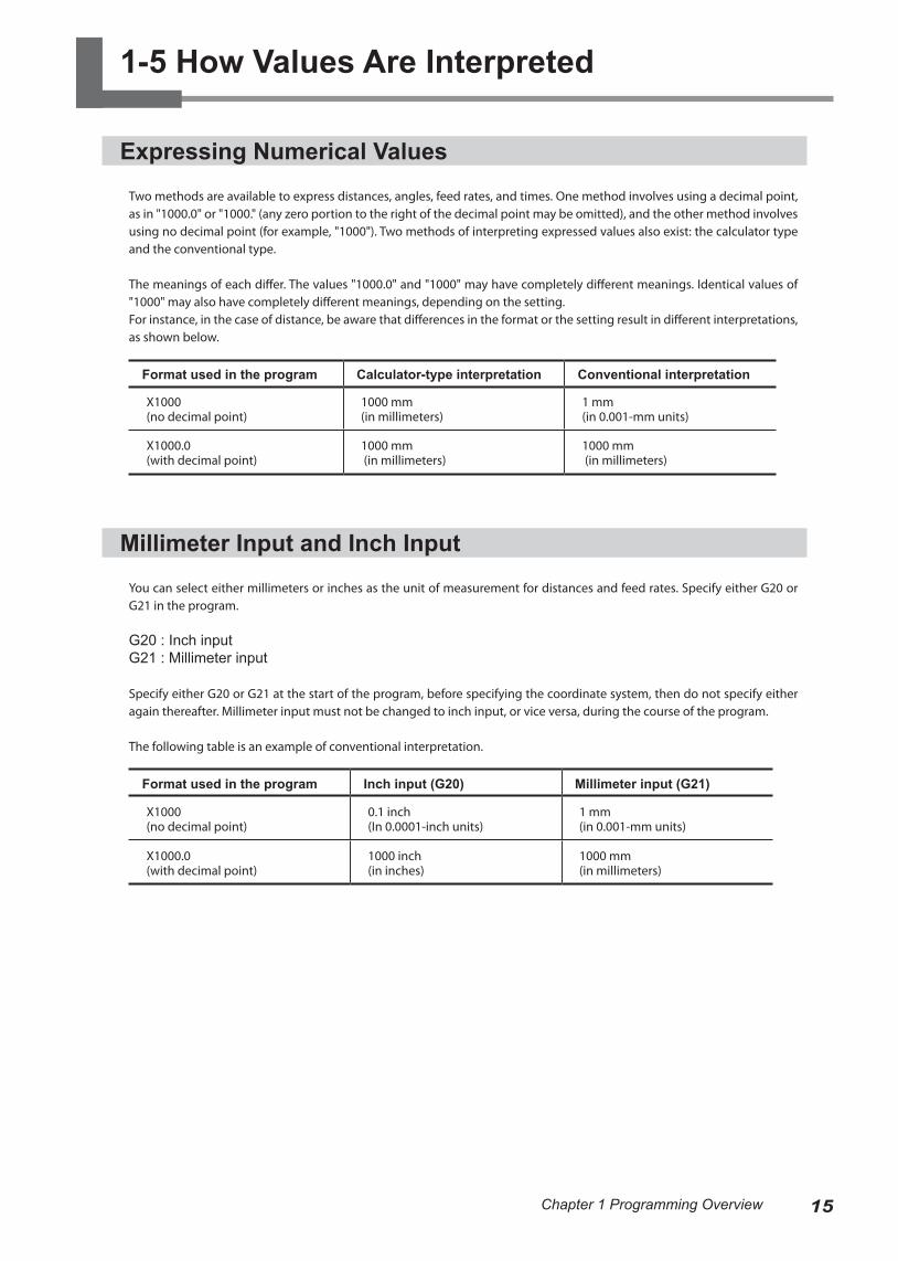
Two methods are available to express distances, angles, feed rates, and times. One method involves using a decimal point, as in "1000.0" or "1000." (any zero portion to the right of the decimal point may be omitted), and the other method involves using no decimal point (for example, "1000"). Two methods of interpreting expressed values also exist: the calculator type and the conventional type.
The meanings of each differ. The values "1000.0" and "1000" may have completely different meanings. Identical values of "1000" may also have completely different meanings, depending on the setting.For instance, in the case of distance, be aware that differences in the format or the setting result in different interpretations, as shown below.
Format used in the program Calculator-type interpretation Conventional interpretation
X1000(no decimal point)
1000 mm(in millimeters)
1 mm(in 0.001-mm units)
X1000.0(with decimal point)
1000 mm (in millimeters)
1000 mm (in millimeters)
Millimeter Input and Inch Input
You can select either millimeters or inches as the unit of measurement for distances and feed rates. Specify either G20 or G21 in the program.
G20 : Inch inputG21 : Millimeter input
Specify either G20 or G21 at the start of the program, before specifying the coordinate system, then do not specify either again thereafter. Millimeter input must not be changed to inch input, or vice versa, during the course of the program.
The following table is an example of conventional interpretation.
Format used in the program Inch input (G20) Millimeter input (G21)
X1000(no decimal point)
0.1 inch(In 0.0001-inch units)
1 mm(in 0.001-mm units)
X1000.0(with decimal point)
1000 inch(in inches)
1000 mm(in millimeters)
15Chapter 1 Programming Overview
Interpretation Methods and Units of Values
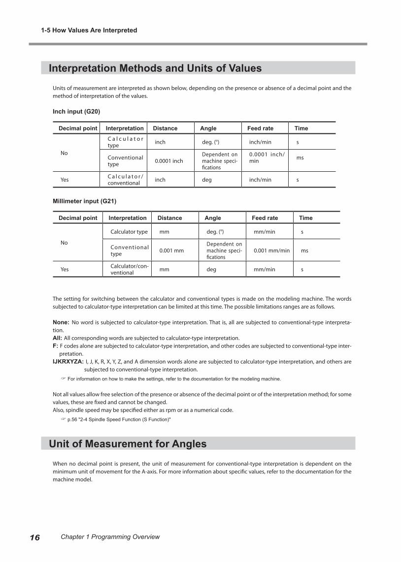
Units of measurement are interpreted as shown below, depending on the presence or absence of a decimal point and the method of interpretation of the values.
Inch input (G20)
Decimal point Interpretation Distance Angle Feed rate Time
No
C a l c u l a t o r type inch deg. (°) inch/min s
Conventional type 0.0001 inch
Dependent on machine speci-fications
0.0001 inch/min ms
Yes C a l c u l a t o r /conventional inch deg inch/min s
Millimeter input (G21)
Decimal point Interpretation Distance Angle Feed rate Time
No
Calculator type mm deg. (°) mm/min s
Conventional type 0.001 mm
Dependent on machine speci-fications
0.001 mm/min ms
Yes Calculator/con-ventional mm deg mm/min s
The setting for switching between the calculator and conventional types is made on the modeling machine. The words subjected to calculator-type interpretation can be limited at this time. The possible limitations ranges are as follows.
None: No word is subjected to calculator-type interpretation. That is, all are subjected to conventional-type interpreta-tion.All: All corresponding words are subjected to calculator-type interpretation.F: F codes alone are subjected to calculator-type interpretation, and other codes are subjected to conventional-type inter-
pretation.IJKRXYZA: I, J, K, R, X, Y, Z, and A dimension words alone are subjected to calculator-type interpretation, and others are
subjected to conventional-type interpretation.
For information on how to make the settings, refer to the documentation for the modeling machine.
Not all values allow free selection of the presence or absence of the decimal point or of the interpretation method; for some values, these are fixed and cannot be changed.Also, spindle speed may be specified either as rpm or as a numerical code.
p.56 "2-4 Spindle Speed Function (S Function)"
Unit of Measurement for Angles
When no decimal point is present, the unit of measurement for conventional-type interpretation is dependent on the minimum unit of movement for the A-axis. For more information about specific values, refer to the documentation for the machine model.
1-5 How Values Are Interpreted
16 Chapter 1 Programming Overview
1-6 Sample Program
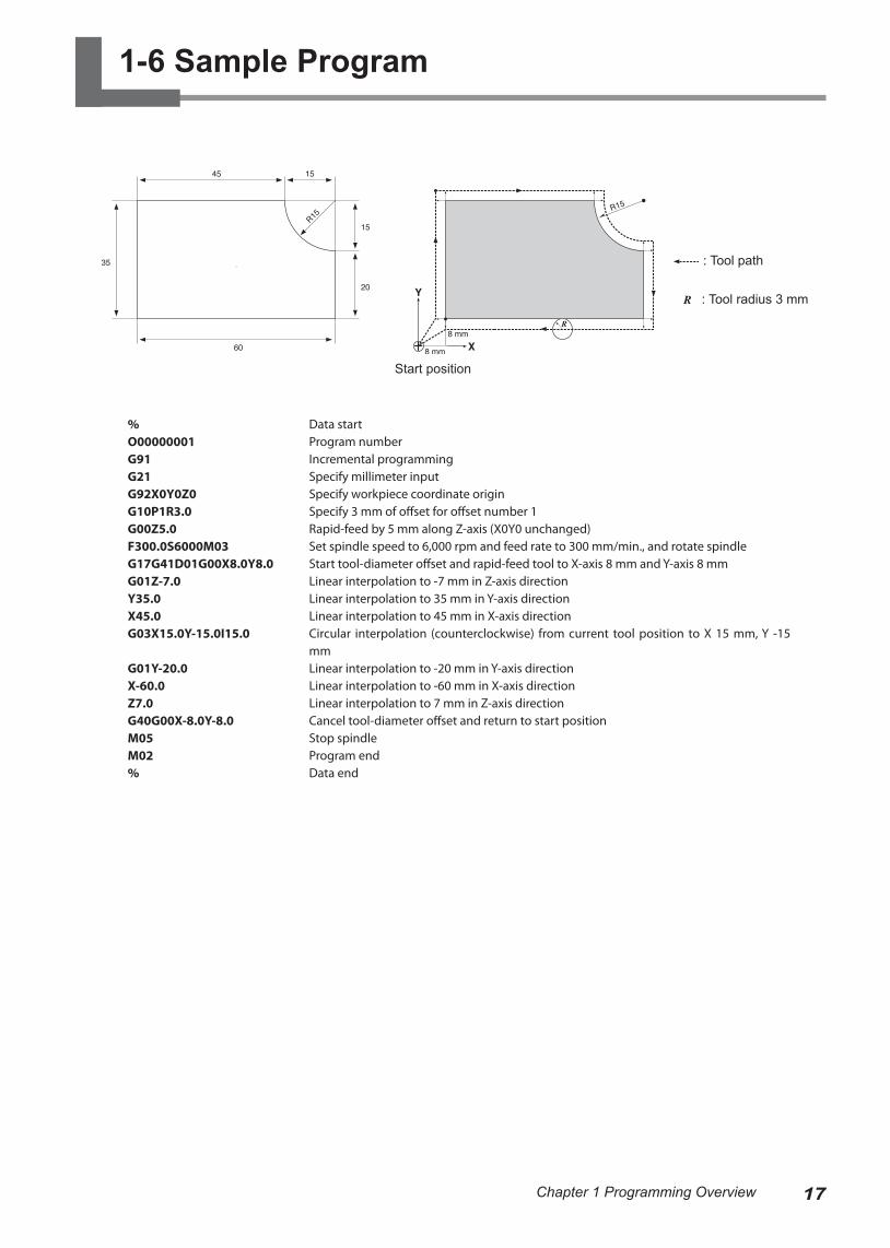
%O00000001G91G21G92X0Y0Z0G10P1R3.0G00Z5.0F300.0S6000M03G17G41D01G00X8.0Y8.0G01Z-7.0Y35.0X45.0G03X15.0Y-15.0I15.0
G01Y-20.0X-60.0Z7.0G40G00X-8.0Y-8.0M05M02%
Data startProgram numberIncremental programmingSpecify millimeter inputSpecify workpiece coordinate originSpecify 3 mm of offset for offset number 1Rapid-feed by 5 mm along Z-axis (X0Y0 unchanged)Set spindle speed to 6,000 rpm and feed rate to 300 mm/min., and rotate spindleStart tool-diameter offset and rapid-feed tool to X-axis 8 mm and Y-axis 8 mmLinear interpolation to -7 mm in Z-axis directionLinear interpolation to 35 mm in Y-axis directionLinear interpolation to 45 mm in X-axis directionCircular interpolation (counterclockwise) from current tool position to X 15 mm, Y -15 mmLinear interpolation to -20 mm in Y-axis directionLinear interpolation to -60 mm in X-axis directionLinear interpolation to 7 mm in Z-axis directionCancel tool-diameter offset and return to start positionStop spindleProgram endData end
: Tool path
Start position
: Tool radius 3 mm
17Chapter 1 Programming Overview

18

19
Chapter 2 Code Reference

20 Chapter 2 Code Reference
2-1 Explanatory Notes
Format
Words in square brackets ("[]") may be omitted.Parameters are given in italics (such as "x," "y," and "feed rate"). A "parameter" is a numerical value appended as an argument to a dimension word.Words enclosed in curly brackets ("{}") are a range of available selections. Any one may be specified. For example:
{ } G40 [X x] [Y y]
uses this shorthand to indicate the following possible selections.
G00G40G00G40X15000G00G40Y5000G00G40X15000Y5000G01G40G01G40X15000G01G40Y5000G01G40X15000Y5000
Parameters
The range and functions of a parameter are shown in table form."Range 1," and "Range 2," are shorthand expressions for ranges in which an error does not occur. They correspond to the following ranges of values.
Range Decimal point Range of values
Range1
No -99999999 to 99999999
Yes
-99999.999 to 99999.999 (inch input, distance/feed rate)-9999.9999 to 9999.9999 (millimeter input, distance/feed rate)-99999.999 to 99999.999 (other parameters)
Range2 Yes/No -99999999 to 99999999
When a parameter range is dependent on the mechanical specifications of the modeling machine, it is so indicated by ex-pressions such as "dependent on machine specifications." To determine the specific values, refer to the documentation for the modeling machine.
G00G01

21Chapter 2 Code Reference
2-2 Preparatory Functions (G Functions)
G00 <Positioning>
Format
G00[X x][Y y][Z z][A a]
Parameter Function Acceptable range Effective range
x X-axis coordinate of move-ment destination Range 1 Maximum cutting area
y Y-axis coordinate of move-ment destination Range 1 Maximum cutting area
z Z-axis coordinate of move-ment destination Range 1 Maximum cutting area
a A-axis coordinate of move-ment destination (angle)
Dependent on machine specifications Maximum cutting area
Description
This effects rapid-feed movement in a straight line from the current tool position to the specified coordinate point. G00 ignores any feed rate set by an F code, and always effects movement at maximum speed. When an override has been set on the modeling machine, however, operation is performed according to that setting.
The destination's coordinates are specified with X x, Y y, Z z, and A a. Specifying values for every one of these addresses (X x, Y y, Z z, and A a) is not necessary. For example:G00X100
specifies movement along only the X axis, with no movement on the Y, Z, or A axes. This is also the case when only the Y axis, Z axis, X and Y axes, Y and Z axes, or Z and Y axes are specified. The axis that can be specified simultaneously might be limited according to the model. For more information,refer to the documentation for the modeling machine.
G00 is also effective outside the block until a word of the same group is encountered. Unless G01, G02, or G03 is used in the block after specifying G00, the destination for movement can be specified by using only X x, Y y, Z z, and A a. For example:G00X100Y100Z5
If the tool encounters an obstacle during movement, steps must be taken to prevent the tool from striking the object, and one way to do this is to move each axes one at a time. An example of this would be to use the absolute specification "G00Z5000" to raise the tool, followed by "X1000Y1000" for horizontal movement.
Current position Current position

2-2 Preparatory Functions (G Functions)
22 Chapter 2 Code Reference
G01 <Linear Interpolation>
FormatG01[X x][Y y][Z z][A a]
Parameter Function Acceptable range Effective range
x X-axis coordinate of move-ment destination Range 1 Maximum cutting area
y Y-axis coordinate of move-ment destination Range 1 Maximum cutting area
z Z-axis coordinate of move-ment destination Range 1 Maximum cutting area
a A-axis coordinate of move-ment destination (angle)
Dependent on machine specifications Maximum cutting area
Description
This effects movement in a straight line from the current tool position to the specified coordinate point. Movement is per-formed at the feed rate specified by an F code.
p.58 "2-5 Feed Function (F Function)"
The destination's coordinates are specified with X x, Y y, Z z, and A a addresses. Specifying values for every one of these ad-dresses (X x, Y y, Z z, and A a) is not necessary. For example:G01X100
specifies movement along only the X axis, with no movement on the Y, Z, or A axes. This is also the case when only the Y axis, Z axis, X and Y axes, Y and Z axes, or Z and Y axes are specified. When X x, Y y, Z z, and A a are all specified, the tool moves along all four axes simultaneously.G01 is also effective outside the block until a word of the same group is encountered. Unless G00, G02, or G03 is used in the block after specifying G01, the destination for movement can be specified by using only X x, Y y, Z z, and A a.G01X100Y100Z5
G01 does not include a function for rotating the spindle motor. If the spindle motor is not already turning, an M03 word should be given beforehand to start rotation.
p.54 "M03 and M05 <Spindle Motor Start/Stop>"
2-2 Preparatory Functions (G Functions)
23Chapter 2 Code Reference
G02 and G03 <Circular Interpolation>
Format
G17{ } [X x] [Y y] { }
G18{ } [X x] [Z z] { }
G19{ } [Y y] [Z z] { }
Parameter Function Acceptable range Effective range
x X-axis coordinate of move-ment destination Range 1 Maximum cutting area
y Y-axis coordinate of move-ment destination Range 1 Maximum cutting area
z Z-axis coordinate of move-ment destination Range 1 Maximum cutting area
cx X-axis coordinate of circle (arc) center Range 1 Maximum cutting area
cy Y-axis coordinate of circle (arc) center Range 1 Maximum cutting area
cz Z-axis coordinate of circle (arc) center Range 1 Maximum cutting area
radius Circle (arc) radius Range 1 Maximum cutting area
Description
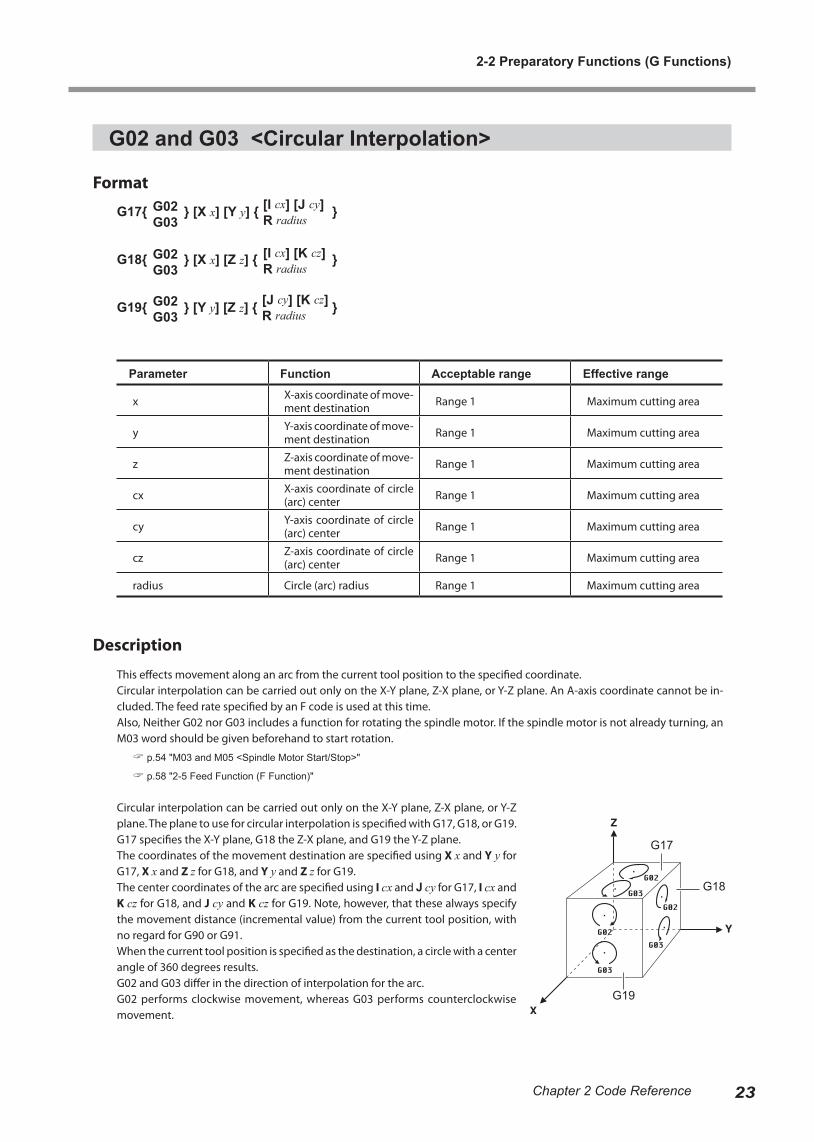
This effects movement along an arc from the current tool position to the specified coordinate.Circular interpolation can be carried out only on the X-Y plane, Z-X plane, or Y-Z plane. An A-axis coordinate cannot be in-cluded. The feed rate specified by an F code is used at this time.Also, Neither G02 nor G03 includes a function for rotating the spindle motor. If the spindle motor is not already turning, an M03 word should be given beforehand to start rotation.
p.54 "M03 and M05 <Spindle Motor Start/Stop>"
p.58 "2-5 Feed Function (F Function)"
Circular interpolation can be carried out only on the X-Y plane, Z-X plane, or Y-Z plane. The plane to use for circular interpolation is specified with G17, G18, or G19. G17 specifies the X-Y plane, G18 the Z-X plane, and G19 the Y-Z plane.The coordinates of the movement destination are specified using X x and Y y for G17, X x and Z z for G18, and Y y and Z z for G19.The center coordinates of the arc are specified using I cx and J cy for G17, I cx and K cz for G18, and J cy and K cz for G19. Note, however, that these always specify the movement distance (incremental value) from the current tool position, with no regard for G90 or G91.When the current tool position is specified as the destination, a circle with a center angle of 360 degrees results.G02 and G03 differ in the direction of interpolation for the arc. G02 performs clockwise movement, whereas G03 performs counterclockwise movement.
G17
G18
G19
G02G03
G02G03
G02G03
[I cx] [J cy]R radius
[I cx] [K cz]R radius
[J cy] [K cz]R radius

2-2 Preparatory Functions (G Functions)
24 Chapter 2 Code Reference
Examples are shown in the figure below (for incremental values).
Specifying the radius of the arc (or circle) instead of the arc’s center coordinates is also possible. The radius of the arc is speci-fied with R radius. This method is useful when numerical values read from a drawing can be used directly.
Two circles passing through two points exist, and so one or the other must be specified. One or the other can be specified by specifying a positive value for the radius of an arc having a center angle of 180 degrees or less and annegative value for the radius of an arc having a center angle exceeding 180 degrees.
G02 and G03, as well as G17, G18, and G19, are also effective outside the block until a different word of the samegroup is encountered.
Executing a G41 or G42 code in the same block as a G02 or G03 code results in an error.In cases such as when the arc’s radius is extremely large, linear interpolation may be performed.
2-2 Preparatory Functions (G Functions)
25Chapter 2 Code Reference
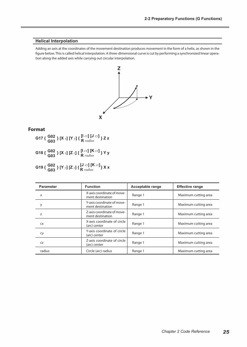
Helical InterpolationAdding an axis at the coordinates of the movement destination produces movement in the form of a helix, as shown in the figure below. This is called helical interpolation. A three-dimensional curve is cut by performing a synchronized linear opera-tion along the added axis while carrying out circular interpolation.
Format
G17 { } [X x] [Y y] { } Z z
G18 { } [X x] [Z z] { } Y y
G19 { } [Y y] [Z z] { } X x
Parameter Function Acceptable range Effective range
x X-axis coordinate of move-ment destination Range 1 Maximum cutting area
y Y-axis coordinate of move-ment destination Range 1 Maximum cutting area
z Z-axis coordinate of move-ment destination Range 1 Maximum cutting area
cx X-axis coordinate of circle (arc) center Range 1 Maximum cutting area
cy Y-axis coordinate of circle (arc) center Range 1 Maximum cutting area
cz Z-axis coordinate of circle (arc) center Range 1 Maximum cutting area
radius Circle (arc) radius Range 1 Maximum cutting area
G02G03
G02G03
G02G03
[I cx] [J cy]R radius
[I cx] [K cz]R radius
[J cy] [K cz]R radius
2-2 Preparatory Functions (G Functions)
26 Chapter 2 Code Reference
G04 <Dwell>
Format
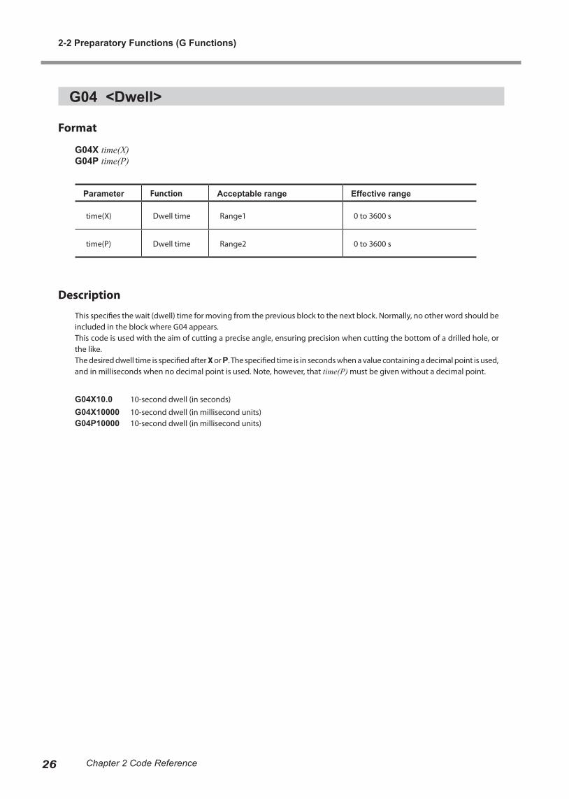
G04X time(X)G04P time(P)
Parameter Function Acceptable range Effective range
time(X) Dwell time Range1 0 to 3600 s
time(P) Dwell time Range2 0 to 3600 s
Description
This specifies the wait (dwell) time for moving from the previous block to the next block. Normally, no other word should be included in the block where G04 appears.This code is used with the aim of cutting a precise angle, ensuring precision when cutting the bottom of a drilled hole, or the like.The desired dwell time is specified after X or P. The specified time is in seconds when a value containing a decimal point is used, and in milliseconds when no decimal point is used. Note, however, that time(P) must be given without a decimal point.
G04X10.0 10-second dwell (in seconds)
G04X10000 10-second dwell (in millisecond units)G04P10000 10-second dwell (in millisecond units)
2-2 Preparatory Functions (G Functions)
27Chapter 2 Code Reference
G10 <Data Setting>
Format
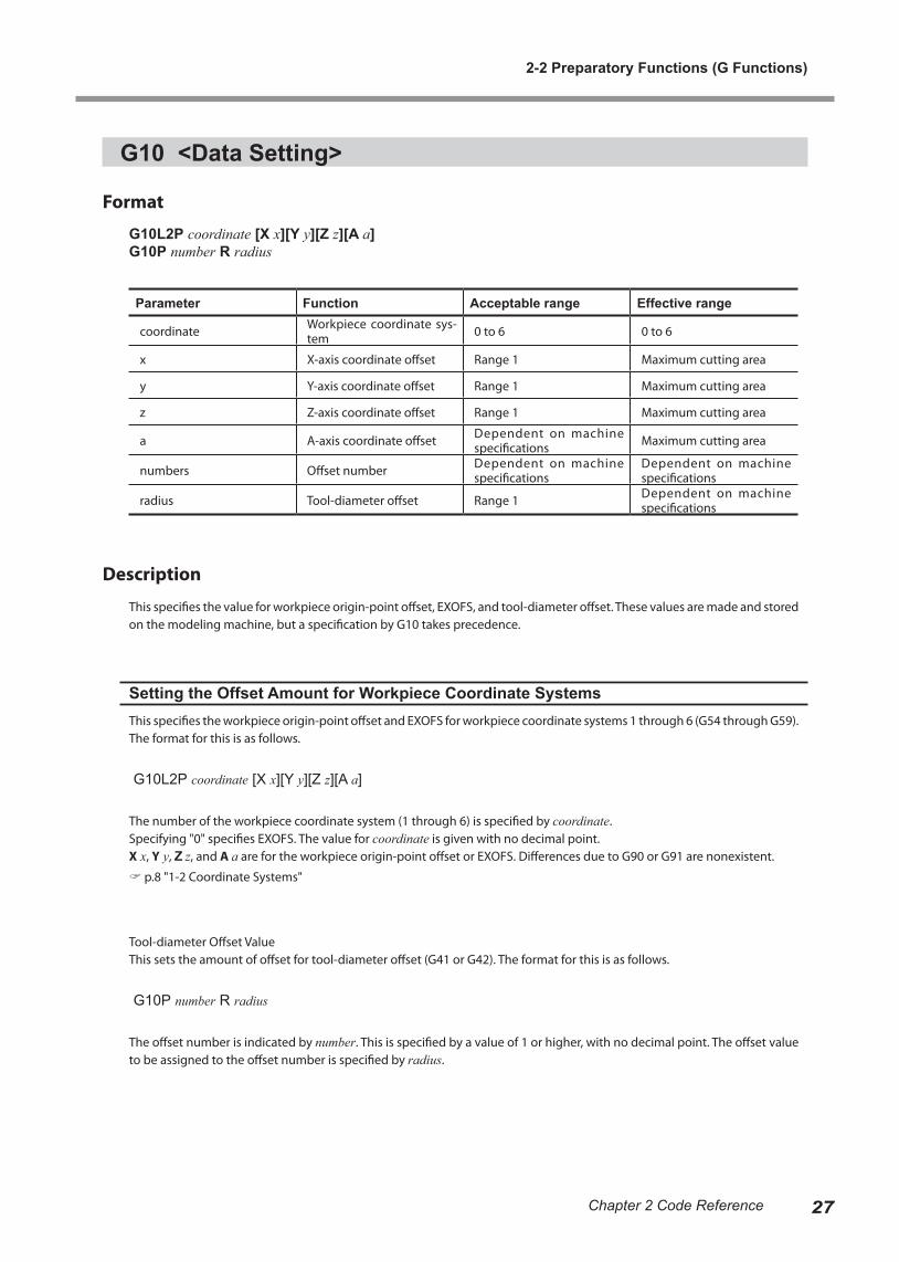
G10L2P coordinate [X x][Y y][Z z][A a]G10P number R radius
Parameter Function Acceptable range Effective range
coordinate Workpiece coordinate sys-tem 0 to 6 0 to 6
x X-axis coordinate offset Range 1 Maximum cutting area
y Y-axis coordinate offset Range 1 Maximum cutting area
z Z-axis coordinate offset Range 1 Maximum cutting area
a A-axis coordinate offset Dependent on machine specifications Maximum cutting area
numbers Offset number Dependent on machine specifications
Dependent on machine specifications
radius Tool-diameter offset Range 1 Dependent on machine specifications
Description
This specifies the value for workpiece origin-point offset, EXOFS, and tool-diameter offset. These values are made and stored on the modeling machine, but a specification by G10 takes precedence.
Setting the Offset Amount for Workpiece Coordinate SystemsThis specifies the workpiece origin-point offset and EXOFS for workpiece coordinate systems 1 through 6 (G54 through G59). The format for this is as follows.
G10L2P coordinate [X x][Y y][Z z][A a]
The number of the workpiece coordinate system (1 through 6) is specified by coordinate.Specifying "0" specifies EXOFS. The value for coordinate is given with no decimal point.X x, Y y, Z z, and A a are for the workpiece origin-point offset or EXOFS. Differences due to G90 or G91 are nonexistent.
p.8 "1-2 Coordinate Systems"
Tool-diameter Offset ValueThis sets the amount of offset for tool-diameter offset (G41 or G42). The format for this is as follows.
G10P number R radius
The offset number is indicated by number. This is specified by a value of 1 or higher, with no decimal point. The offset value to be assigned to the offset number is specified by radius.

2-2 Preparatory Functions (G Functions)
28 Chapter 2 Code Reference
G17, G18, and G19 <Plane>
Format
G17G18G19
Description
This specifies a plane for circular interpolation (G02 or G03).G17 specifies the X-Y plane, G18 the Z-X plane, and G19 the Y-Z plane. Each of these is normally used in combination with G02 or G03 in the same block.
p.23 "G02 and G03 <Circular Interpolation>"
X-Y plane
Y-Z plane
Z-X plane
2-2 Preparatory Functions (G Functions)
29Chapter 2 Code Reference
G20 and G21 <Measurement Unit>
Format
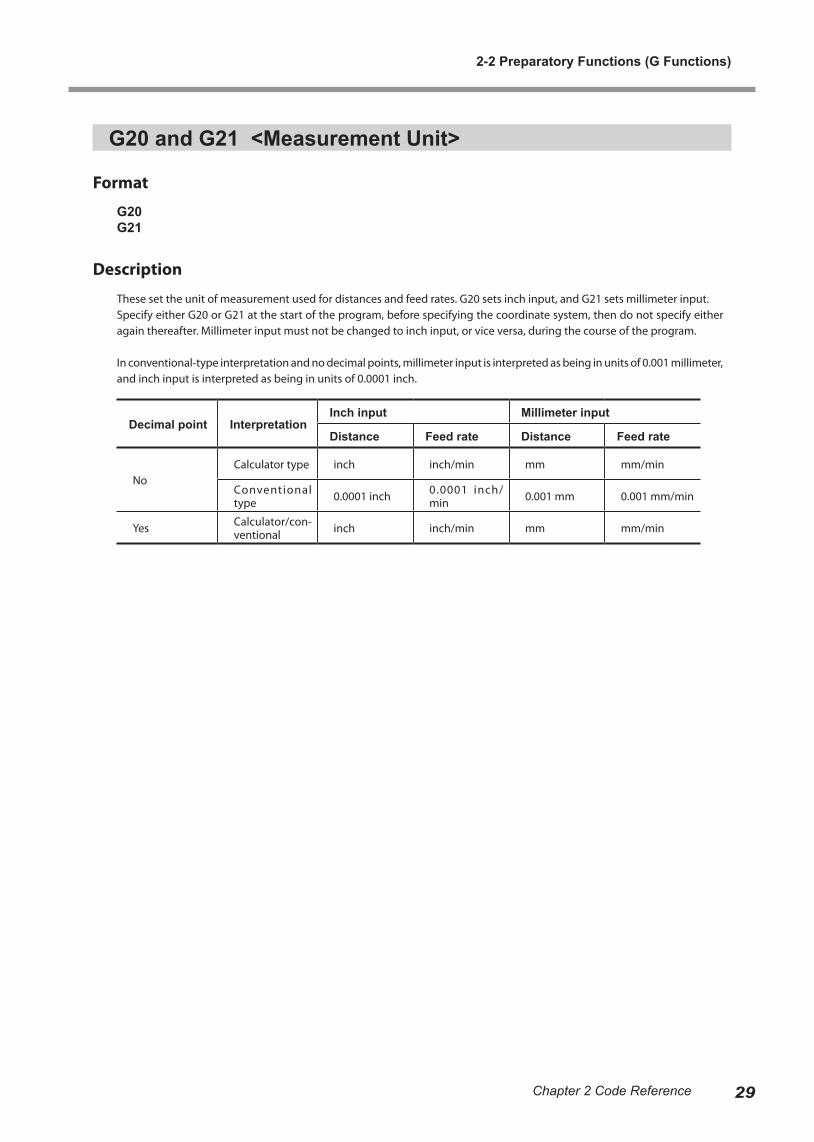
G20G21
Description
These set the unit of measurement used for distances and feed rates. G20 sets inch input, and G21 sets millimeter input.Specify either G20 or G21 at the start of the program, before specifying the coordinate system, then do not specify either again thereafter. Millimeter input must not be changed to inch input, or vice versa, during the course of the program.
In conventional-type interpretation and no decimal points, millimeter input is interpreted as being in units of 0.001 millimeter, and inch input is interpreted as being in units of 0.0001 inch.
Decimal point InterpretationInch input Millimeter input
Distance Feed rate Distance Feed rate
NoCalculator type inch inch/min mm mm/min
Conventional type 0.0001 inch 0.0001 inch/
min 0.001 mm 0.001 mm/min
Yes Calculator/con-ventional inch inch/min mm mm/min
2-2 Preparatory Functions (G Functions)
30 Chapter 2 Code Reference
G28 <Reference-point Return>
Format
G28[X x][Y y][Z z]
Parameter Function Acceptable range Effective range
x X-axis coordinate of mid-point Range 1 Maximum cutting area
y Y-axis coordinate of mid-point Range 1 Maximum cutting area
z Z-axis coordinate of mid-point Range 1 Maximum cutting area
Description
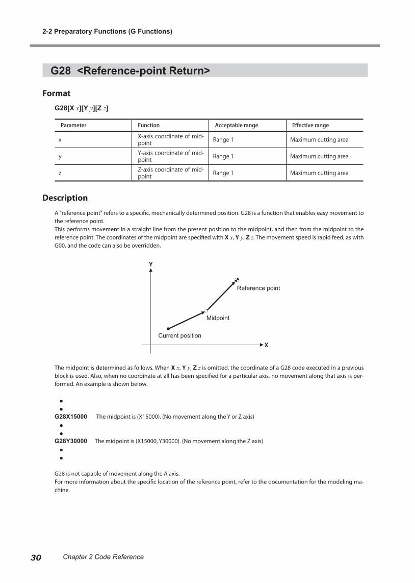
A "reference point" refers to a specific, mechanically determined position. G28 is a function that enables easy movement to the reference point.This performs movement in a straight line from the present position to the midpoint, and then from the midpoint to the reference point. The coordinates of the midpoint are specified with X x, Y y, Z z. The movement speed is rapid feed, as with G00, and the code can also be overridden.
The midpoint is determined as follows. When X x, Y y, Z z is omitted, the coordinate of a G28 code executed in a previous block is used. Also, when no coordinate at all has been specified for a particular axis, no movement along that axis is per-formed. An example is shown below.
● ●G28X15000 The midpoint is (X15000). (No movement along the Y or Z axis) ● ●G28Y30000 The midpoint is (X15000, Y30000). (No movement along the Z axis) ● ●
G28 is not capable of movement along the A axis.For more information about the specific location of the reference point, refer to the documentation for the modeling ma-chine.
Current position
Midpoint
Reference point
2-2 Preparatory Functions (G Functions)
31Chapter 2 Code Reference
G39 <Corner-offset Circular Interpolation>
Format
G39[X x][Y y]
Parameter Function Acceptable range Effective range
x X-axis coordinate in des-tination direction Range 1 Maximum cutting area
y Y-axis coordinate in des-tination direction Range 1 Maximum cutting area
Description
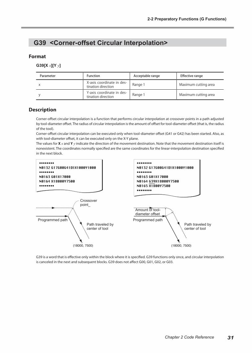
Corner-offset circular interpolation is a function that performs circular interpolation at crossover points in a path adjusted by tool-diameter offset. The radius of circular interpolation is the amount of offset for tool-diameter offset (that is, the radius of the tool).Corner-offset circular interpolation can be executed only when tool-diameter offset (G41 or G42) has been started. Also, as with tool-diameter offset, it can be executed only on the X-Y plane.The values for X x and Y y indicate the direction of the movement destination. Note that the movement destination itself is nonexistent. The coordinates normally specified are the same coordinates for the linear-interpolation destination specified in the next block.
G39 is a word that is effective only within the block where it is specified. G39 functions only once, and circular interpolation is canceled in the next and subsequent blocks. G39 does not affect G00, G01, G02, or G03.
Crossover point_
Programmed pathPath traveled by center of tool
Amount of tool-diameter offset
Programmed pathPath traveled by center of tool

2-2 Preparatory Functions (G Functions)
32 Chapter 2 Code Reference
G40, G41, and G42 <Tool-diameter Offset>
Format
{ } G40 [X x][Y y]
G17{ } { } D number [X x] [Y y]
Parameter Function Acceptable range Effective range
x X - a x i s c o o r d i n a t e o f movement destination Range 1 Maximum cutting area
y Y - a x i s c o o r d i n a t e o f movement destination Range 1 Maximum cutting area
number Offset number Dependent on machine specification
Dependent on machine specification
Description
Shifting the tool path by an amount equal to the radius of the tool is called "tool-diameter offset."Using this function makes it possible to input the values from a drawing as coordinates with no need for modification, thus facilitating programming. Also, if cutting is to be performed with a tool that has a different tool diameter, changing the amount of offset is the only modification that is necessary.
G40 Cancel tool-diameter offsetG41 Tool-diameter offset -- leftG42 Tool-diameter offset -- right
: Path traveled by center of tool
Tool
G00G01
G00G01
G41G42
2-2 Preparatory Functions (G Functions)
33Chapter 2 Code Reference
Restrictions on Tool-diameter OffsetTool-diameter offset is subject to the next restrictions.
1. Tool-diameter offset functions only in the X-Y plane. Z- and A-axis coordinates are not affected by tool-diameter offset, and movement along these axes is performed as specified in the program.2. To start and end tool-diameter offset, be sure to use G00 (positioning) and G01 (linear interpolation). Attempting to start or end it using circular interpolation results in an error.3. Specifying a plane other than the X-Y plane with G18 or G19 results in an error.4. Setting a coordinate system (G10, G54, G55, G56, G57, G58, G59, or G92) while tool-diameter offset is in effect results in an error.5. Never position two or more blocks without X- and Y-axis motion instructions (such as a miscellaneous function or dwell) next to one other while tool-diameter offset is in effect. Doing so may result in excessive or insufficient cutting depth.6. No interference checking for the tool is performed. However, attempting to cut the inner side of a circle or arc with an offset value that is larger than the radius of the circle or arc results in an error.7. To change the offset number (D number) or change "tool-diameter offset -- left" or "-- right," first cancel tool-diameter offset with G40, then specify G41 or G42 again.8. Executing fixed-cycle operation (G80, G81, G82, G83, G85, G86, or G89) or scaling (G50 or G51) results in an error.9.Performing reference-point return (G28) while tool-diameter offset is in effect results in an error
Setting the Amount of OffsetThe amount by which the tool is shifted is specified by D number. Note, however, that the shift distance is not given directly with number. The offset value is either preset on the modeling machine or specified with G10, then specified with D number for the number of the offset value. The value for number is given as a numerical value of 1 or higher, with no decimal point.
1. Making the Setting on the Modeling MachinePreset the offset value on the modeling machine.
For information on how to make the setting, refer to the documentation for the modeling machine.
2. Specified Using G10G10 P number R radius
Parameter Function Acceptable range Effective range
number Offset number Dependent on machine specification
Dependent on machine specification
radius To o l - d i a m e t e r o f f s e t value Range 1 Dependent on machine
specification
Specification by G10 takes precedence over the setting made on the modeling machine.The offset value for offset number 0 is always 0 (zero). No other value can be specified for offset number 0.
2-2 Preparatory Functions (G Functions)
34 Chapter 2 Code Reference
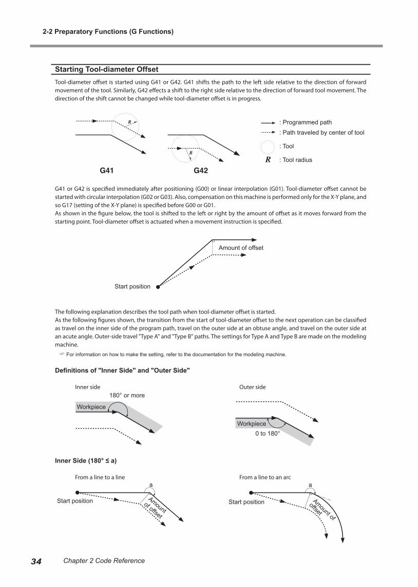
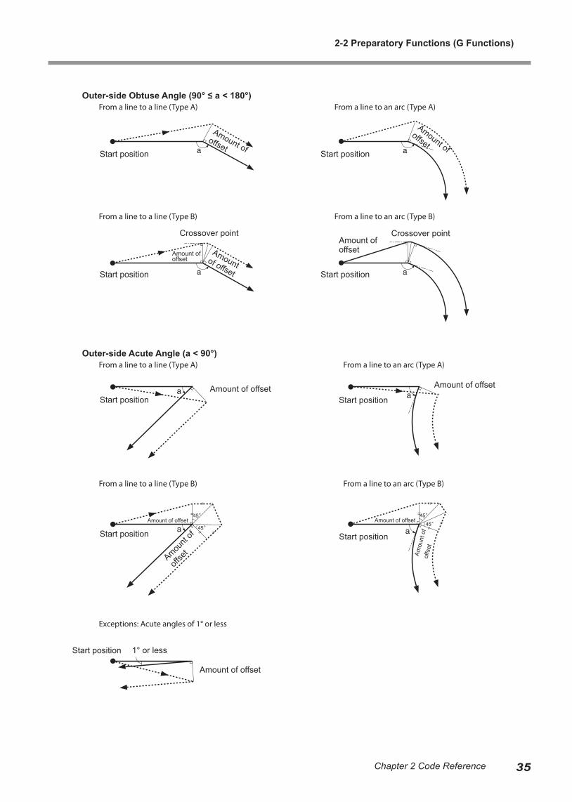
Starting Tool-diameter OffsetTool-diameter offset is started using G41 or G42. G41 shifts the path to the left side relative to the direction of forward movement of the tool. Similarly, G42 effects a shift to the right side relative to the direction of forward tool movement. The direction of the shift cannot be changed while tool-diameter offset is in progress.
G41 or G42 is specified immediately after positioning (G00) or linear interpolation (G01). Tool-diameter offset cannot be started with circular interpolation (G02 or G03). Also, compensation on this machine is performed only for the X-Y plane, and so G17 (setting of the X-Y plane) is specified before G00 or G01.As shown in the figure below, the tool is shifted to the left or right by the amount of offset as it moves forward from the starting point. Tool-diameter offset is actuated when a movement instruction is specified.
The following explanation describes the tool path when tool-diameter offset is started.As the following figures shown, the transition from the start of tool-diameter offset to the next operation can be classified as travel on the inner side of the program path, travel on the outer side at an obtuse angle, and travel on the outer side at an acute angle. Outer-side travel "Type A" and "Type B" paths. The settings for Type A and Type B are made on the modeling machine.
For information on how to make the setting, refer to the documentation for the modeling machine.
Definitions of "Inner Side" and "Outer Side"
Inner side Outer side
Inner Side (180° ≤ a)
From a line to a line From a line to an arc
: Programmed path
: Path traveled by center of tool
: Tool
: Tool radius
Amount of offset
Start position
Workpiece
180° or more
0 to 180°Workpiece
Start position Amount of
offset
Start positionAmount
of offset
2-2 Preparatory Functions (G Functions)
35Chapter 2 Code Reference
Outer-side Obtuse Angle (90° ≤ a < 180°) From a line to a line (Type A) From a line to an arc (Type A)
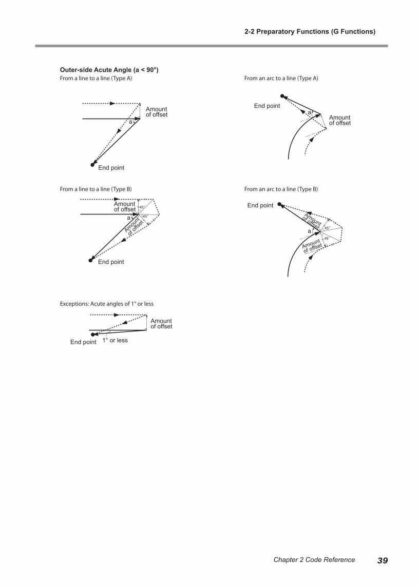
Outer-side Acute Angle (a < 90°) From a line to a line (Type A) From a line to an arc (Type A)
Start position
Amount of offset
Amount of offset
Amount of
offsetStart position
Start position Start position
Crossover point Crossover point
Start position Start positionAmount of offset Amount of offset
Start position Start position
Amount of offset Amount of offset
Start position 1° or less
Amount of offset
Amount of offset
Amount of offset
Amount
of
offse
t Amou
nt o
f of
fset
From a line to a line (Type B) From a line to an arc (Type B)
From a line to a line (Type B) From a line to an arc (Type B)
Exceptions: Acute angles of 1° or less
2-2 Preparatory Functions (G Functions)
36 Chapter 2 Code Reference
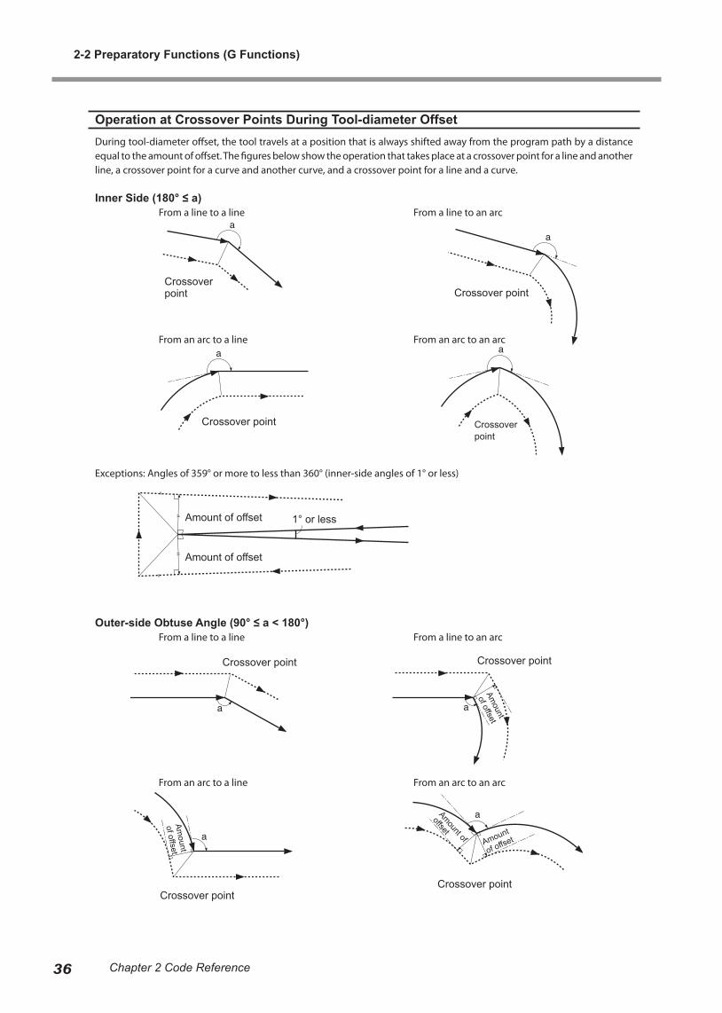
Operation at Crossover Points During Tool-diameter OffsetDuring tool-diameter offset, the tool travels at a position that is always shifted away from the program path by a distance equal to the amount of offset. The figures below show the operation that takes place at a crossover point for a line and another line, a crossover point for a curve and another curve, and a crossover point for a line and a curve.
Inner Side (180° ≤ a) From a line to a line From a line to an arc
Outer-side Obtuse Angle (90° ≤ a < 180°) From a line to a line From a line to an arc
Amount of offset
Crossover point
1° or less
Crossover point
Crossover point
Crossover point
Amount of offset
Crossover point
Crossover pointCrossover point
Crossover point
Amount
of offset
Amount
of offset
Amount
of offset
Amount of
offset
From an arc to a line From an arc to an arc
Exceptions: Angles of 359° or more to less than 360° (inner-side angles of 1° or less)
From an arc to a line From an arc to an arc
2-2 Preparatory Functions (G Functions)
37Chapter 2 Code Reference
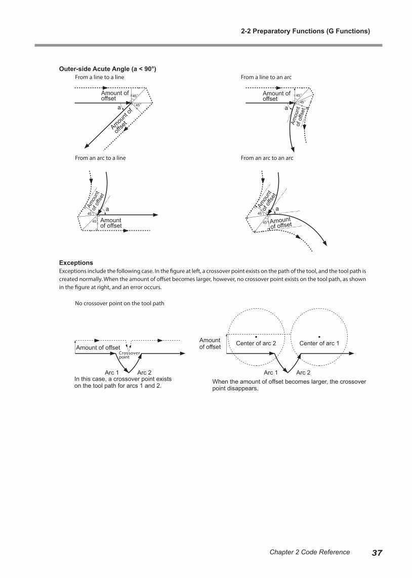
Outer-side Acute Angle (a < 90°) From a line to a line From a line to an arc
From an arc to a line From an arc to an arc
ExceptionsExceptions include the following case. In the figure at left, a crossover point exists on the path of the tool, and the tool path is created normally. When the amount of offset becomes larger, however, no crossover point exists on the tool path, as shown in the figure at right, and an error occurs.
No crossover point on the tool path
Amou
nt
of o
ffset
Amou
nt
of o
ffset
Amount of offset
Amount of offset
Arc 1 Arc 1Arc 2 Arc 2
Center of arc 2 Center of arc 1Amount of offset
In this case, a crossover point exists on the tool path for arcs 1 and 2.
Crossover point
When the amount of offset becomes larger, the crossover point disappears.
Amou
nt
of o
ffset
Amount of offset
Amount of offset
Amount of offset
Amount
of
offse
t
2-2 Preparatory Functions (G Functions)
38 Chapter 2 Code Reference
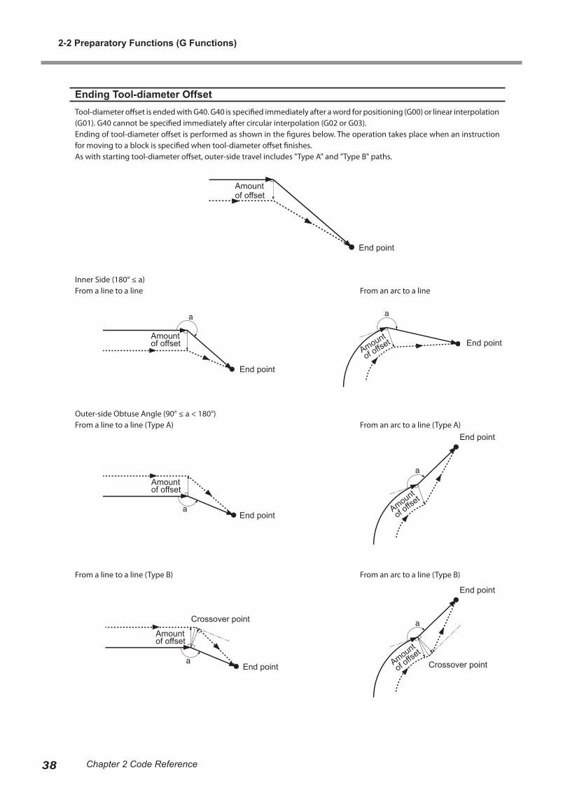
Ending Tool-diameter OffsetTool-diameter offset is ended with G40. G40 is specified immediately after a word for positioning (G00) or linear interpolation (G01). G40 cannot be specified immediately after circular interpolation (G02 or G03).Ending of tool-diameter offset is performed as shown in the figures below. The operation takes place when an instruction for moving to a block is specified when tool-diameter offset finishes.As with starting tool-diameter offset, outer-side travel includes "Type A" and "Type B" paths.
Inner Side (180° ≤ a)From a line to a line From an arc to a line
Outer-side Obtuse Angle (90° ≤ a < 180°)From a line to a line (Type A) From an arc to a line (Type A)
End point
End point
End point
End point
End point
End point
End point
Crossover point
Crossover point
Amount
of offset
Amount
of offse
t
Amount
of offse
t
Amount of offset
Amount of offset
Amount of offset
Amount of offset
From a line to a line (Type B) From an arc to a line (Type B)
2-2 Preparatory Functions (G Functions)
39Chapter 2 Code Reference
Outer-side Acute Angle (a < 90°)From a line to a line (Type A) From an arc to a line (Type A)
End point
End point
End point
End point
End point 1° or less
Amount
of off
set
Amount of offset
Amount of offset
Amount of offset
Amount of offset
From a line to a line (Type B) From an arc to a line (Type B)
Exceptions: Acute angles of 1° or less
Amount
of offset
Amount of offset

2-2 Preparatory Functions (G Functions)
40 Chapter 2 Code Reference
G43 and G49 <Tool-length Offset>
Format
G43H numberG49
Parameter Function Acceptable range Effective range
number Offset number Dependent on machine specification
Dependent on machine specification
Description
This moves the tool along the Z axis by the specified offset amount. It is used to correct for a change in tool length due to a tool change, to keep the position of the tip uniform. This function is enabled only on modeling machines equipped with an ATC (Auto Tool Changer). G43 starts tool-length offset.The amount by which the tool is shifted is specified by H number. Note, however, that the shift distance is not given directly with number. The offset value is preset on the modeling machine, then specified with H number for the number of the offset value. The value for number is given as a numerical value of 1 or higher, with no decimal point.G49 or G43H0 cancels tool-length offset.
If an axis-movement instruction is present within the same block as a G43 instruction, the end point for axis movement is the Z-axis coordinate for the movement destination plus the offset. When no axis-movement instruction is present, the instruction is construed to be for a movement distance of zero, and movement along the Z axis by only an amount equal to the offset is performed. This is the same for both absolute and incremental coordinates.G43 and G49 are instruction in the same group. These instructions remain in effect even outside the block, until a new G43 or G49 instruction is received.The offset value for offset number 0 is always 0 (zero). No other value can be specified for offset number 0.
Specification of the offset value is performed on the modeling machine. Specification by a program is not possible.
For information on how to make the setting, refer to the documentation for the modeling machine.
Sample Program% Data startO0001 Program numberG90 Specify absolute coordinatesG49M06T2 Select tool in stocker No. 2G00Z30000 PositioningX5000Y5000 PositioningG43H1Z1000 Start tool-length offset with offset No. 1 and move to corrected positionF600S5000M03 Rotate spindleG01Z-1000 Linear interpolationX45000Y45000 Linear interpolationZ30000 Linear interpolationM05 Stop spindleG49M06T0 Cancel tool-length offset and return toolM30 Program end% Data end

2-2 Preparatory Functions (G Functions)
41Chapter 2 Code Reference
G50 and G51 <Scaling>
Format
G50G51[X x][Y y][Z z]P scale
Parameter Function Acceptable range Effective range
x X-axis coordinate of refer-ence point Range 1 Maximum cutting area
y Y-axis coordinate of refer-ence point Range 1 Maximum cutting area
z Z-axis coordinate of refer-ence point Range 1 Maximum cutting area
scale Scaling factor Range 1 0.001 to 999.999
Description
G51 executes same-scale enlargement or reduction for each axis, referenced to the specified point. It is used for such applica-tion as the creation of reduced-scale models. Because this instruction affects the entire program, G51 is normally specified immediately after the start of the program.G50 cancels G51.When enlargement or reduction has been specified with G51, it remains in effect until canceled with G50 or another program is executed. The reference point for enlargement or reduction is specified with the addresses X x, Y y, and Z z. When this is not specified, the current tool position is used as the reference point. The scaling factor is specified with P scale. The value for scale is given as a numerical value from 0.00001 to 999.999. A specified scaling factor less than 0.00001 is treated as a factor of 0.00001, and a specified scaling factor lager than 999.999 is similarly taken to be a factor of 999.999.G51 acts upon the X-, Y-, and Z-axis coordinates. A-axis coordinates are not scaled.
Specifying a scaling factor of 0.5 produces results like those shown in the figure below. When length is scaled by a factor of 0.5, the volume ratio becomes 0.125.
Reference Point Reference Point
Scaling factor 1.00Length 1.00Volume 1.00
Scaling factor 0.50Length 0.50Volume 0.125
2-2 Preparatory Functions (G Functions)
42 Chapter 2 Code Reference
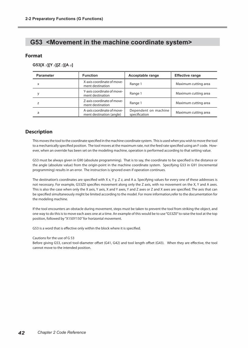
G53 <Movement in the machine coordinate system>
Format
G53[X x][Y s][Z z][A a]
Parameter Function Acceptable range Effective range
x X-axis coordinate of move-ment destination Range 1 Maximum cutting area
y Y-axis coordinate of move-ment destination Range 1 Maximum cutting area
z Z-axis coordinate of move-ment destination Range 1 Maximum cutting area
a A-axis coordinate of move-ment destination (angle)
Dependent on machine specification Maximum cutting area
Description
This moves the tool to the coordinate specified in the machine coordinate system. This is used when you wish to move the tool to a mechanically specified position. The tool moves at the maximum rate, not the feed rate specified using an F code. How-ever, when an override has been set on the modeling machine, operation is performed according to that setting value.
G53 must be always given in G90 (absolute programming). That is to say, the coordinate to be specified is the distance or the angle (absolute value) from the origin-point in the machine coordinate system. Specifying G53 in G91 (incremental programming) results in an error. The instruction is ignored even if operation continues.
The destination’s coordinates are specified with X x, Y y, Z z, and A a. Specifying values for every one of these addresses is not necessary. For example, G53Z0 specifies movement along only the Z axis, with no movement on the X, Y and A axes. This is also the case when only the X axis, Y axis, X and Y axes, Y and Z axes or Z and X axes are specified. The axis that can be specified simultaneously might be limited according to the model. For more information,refer to the documentation for the modeling machine.
If the tool encounters an obstacle during movement, steps must be taken to prevent the tool from striking the object, and one way to do this is to move each axes one at a time. An example of this would be to use “G53Z0” to raise the tool at the top position, followed by “X150Y150” for horizontal movement.
G53 is a word that is effective only within the block where it is specified.
Cautions for the use of G 53 Before giving G53, cancel tool-diameter offset (G41, G42) and tool length offset (G43). When they are effective, the tool cannot move to the intended position.
2-2 Preparatory Functions (G Functions)
43Chapter 2 Code Reference
G54, G55, G56, G57, G58, and G59 <Select Coordinate System>
Format
G54G55G56G57G58G59
Description
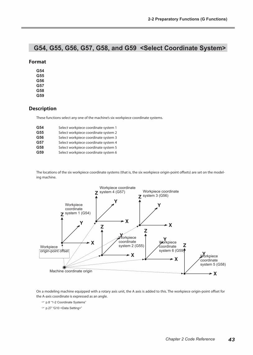
These functions select any one of the machine’s six workpiece coordinate systems.
G54 Select workpiece coordinate system 1G55 Select workpiece coordinate system 2G56 Select workpiece coordinate system 3G57 Select workpiece coordinate system 4G58 Select workpiece coordinate system 5G59 Select workpiece coordinate system 6
The locations of the six workpiece coordinate systems (that is, the six workpiece origin-point offsets) are set on the model-ing machine.
On a modeling machine equipped with a rotary axis unit, the A axis is added to this. The workpiece origin-point offset for the A-axis coordinate is expressed as an angle.
p.8 “1-2 Coordinate Systems”
p.27 “G10 <Data Setting>”
Workpiece coordinate system 1 (G54)
Workpiece origin-point offset
Machine coordinate origin
Workpiece coordinate system 4 (G57) Workpiece coordinate
system 3 (G56)
Workpiece coordinate system 2 (G55)
Workpiece coordinate system 6 (G59)
Workpiece coordinate system 5 (G58)
2-2 Preparatory Functions (G Functions)
44 Chapter 2 Code Reference
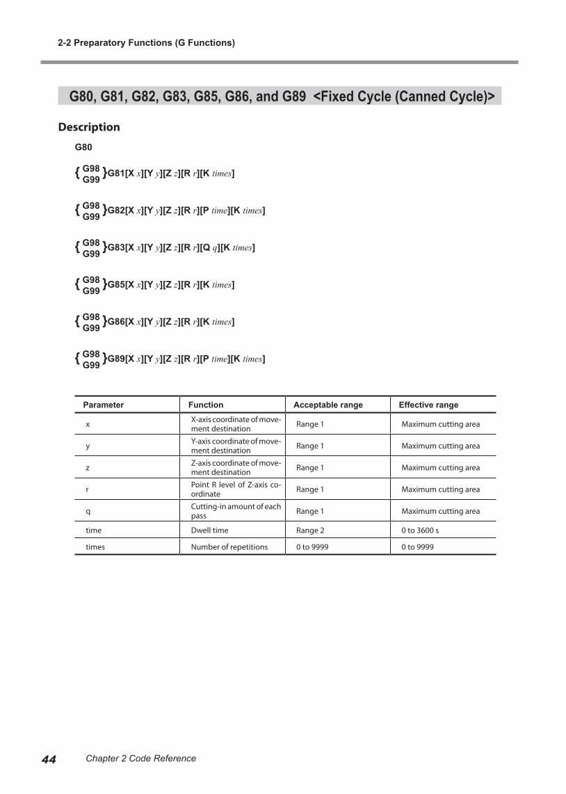
G80, G81, G82, G83, G85, G86, and G89 <Fixed Cycle (Canned Cycle)>
Description
G80
{ G98 }G81[X x][Y y][Z z][R r][K times] G99
{ G98 }G82[X x][Y y][Z z][R r][P time][K times] G99
{ G98 }G83[X x][Y y][Z z][R r][Q q][K times] G99
{ G98 }G85[X x][Y y][Z z][R r][K times] G99
{ G98 }G86[X x][Y y][Z z][R r][K times] G99
{ G98 }G89[X x][Y y][Z z][R r][P time][K times] G99
Parameter Function Acceptable range Effective range
x X-axis coordinate of move-ment destination Range 1 Maximum cutting area
y Y-axis coordinate of move-ment destination Range 1 Maximum cutting area
z Z-axis coordinate of move-ment destination Range 1 Maximum cutting area
r Point R level of Z-axis co-ordinate Range 1 Maximum cutting area
q Cutting-in amount of each pass Range 1 Maximum cutting area
time Dwell time Range 2 0 to 3600 s
times Number of repetitions 0 to 9999 0 to 9999
2-2 Preparatory Functions (G Functions)
45Chapter 2 Code Reference
Description
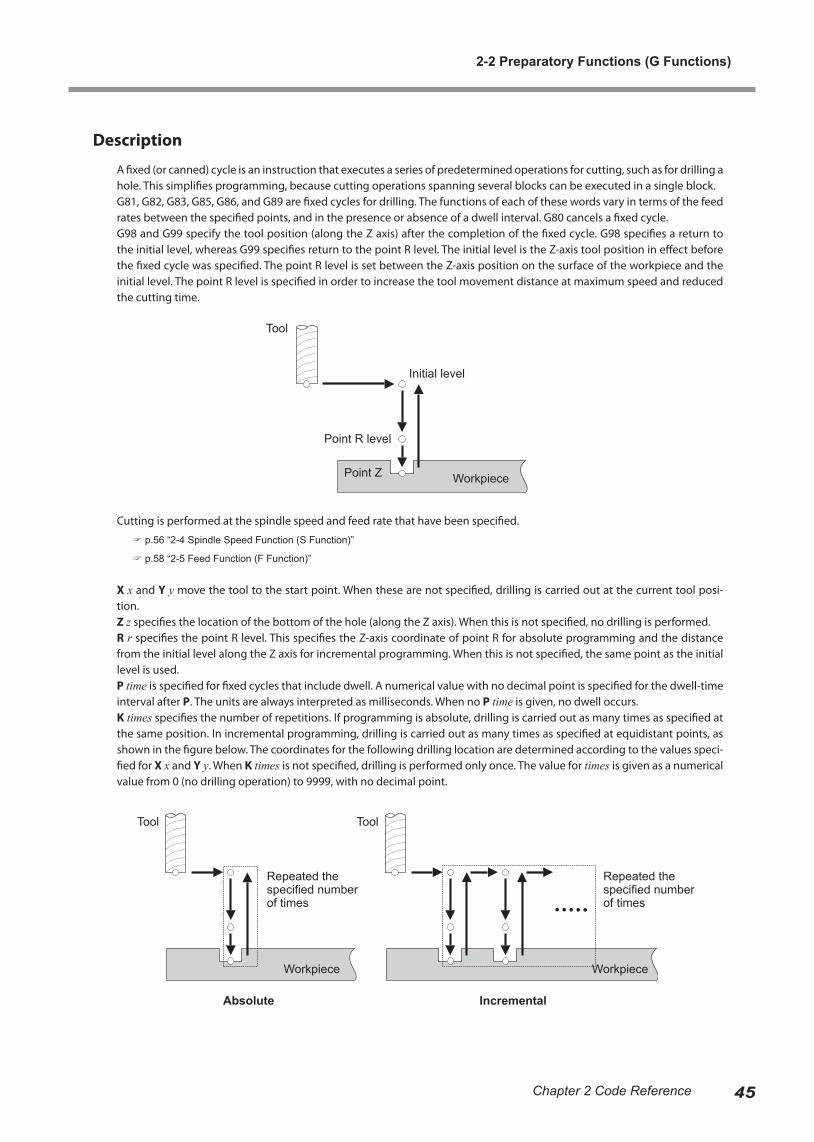
A fixed (or canned) cycle is an instruction that executes a series of predetermined operations for cutting, such as for drilling a hole. This simplifies programming, because cutting operations spanning several blocks can be executed in a single block.G81, G82, G83, G85, G86, and G89 are fixed cycles for drilling. The functions of each of these words vary in terms of the feed rates between the specified points, and in the presence or absence of a dwell interval. G80 cancels a fixed cycle.G98 and G99 specify the tool position (along the Z axis) after the completion of the fixed cycle. G98 specifies a return to the initial level, whereas G99 specifies return to the point R level. The initial level is the Z-axis tool position in effect before the fixed cycle was specified. The point R level is set between the Z-axis position on the surface of the workpiece and the initial level. The point R level is specified in order to increase the tool movement distance at maximum speed and reduced the cutting time.
Cutting is performed at the spindle speed and feed rate that have been specified.
p.56 “2-4 Spindle Speed Function (S Function)”
p.58 “2-5 Feed Function (F Function)”
X x and Y y move the tool to the start point. When these are not specified, drilling is carried out at the current tool posi-tion.Z z specifies the location of the bottom of the hole (along the Z axis). When this is not specified, no drilling is performed.R r specifies the point R level. This specifies the Z-axis coordinate of point R for absolute programming and the distance from the initial level along the Z axis for incremental programming. When this is not specified, the same point as the initial level is used.P time is specified for fixed cycles that include dwell. A numerical value with no decimal point is specified for the dwell-time interval after P. The units are always interpreted as milliseconds. When no P time is given, no dwell occurs.K times specifies the number of repetitions. If programming is absolute, drilling is carried out as many times as specified at the same position. In incremental programming, drilling is carried out as many times as specified at equidistant points, as shown in the figure below. The coordinates for the following drilling location are determined according to the values speci-fied for X x and Y y. When K times is not specified, drilling is performed only once. The value for times is given as a numerical value from 0 (no drilling operation) to 9999, with no decimal point.
Absolute Incremental
Tool Tool
Workpiece Workpiece
Repeated the specified number of times
Repeated the specified number of times
Tool
Initial level
Point R level
Point Z Workpiece
2-2 Preparatory Functions (G Functions)
46 Chapter 2 Code Reference
Fixed cycles can be used only with X-, Y-, and Z-axis coordinates. An A-axis coordinate cannot be included. Also, drilling can be performed only along the Z axis. Selecting the Y-Z plane or Z-X plane with G18 or G19 is not possible.None of the fixed cycles includes a function for starting the spindle motor. If the spindle motor is not already turning, an M03 word should be given beforehand to start rotation. Executing a fixed cycle while the motor is not rotating results in an error.
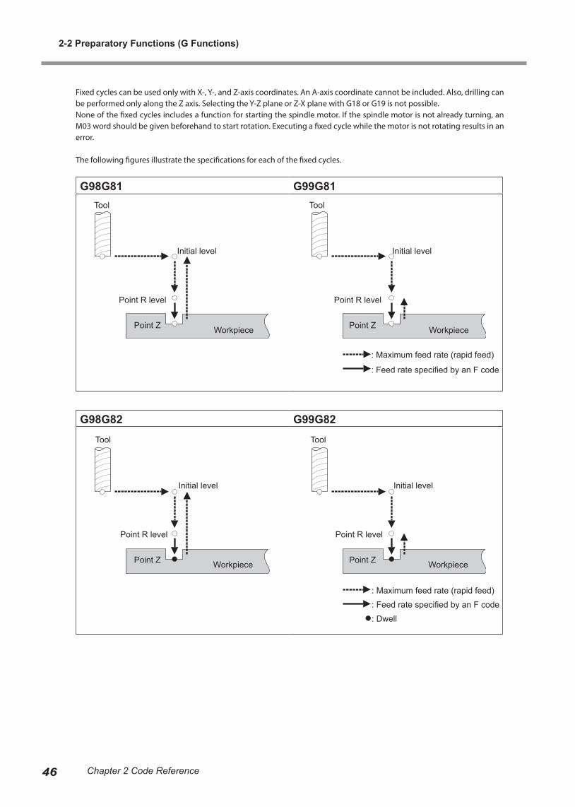
The following figures illustrate the specifications for each of the fixed cycles.
G98G81 G99G81
G98G82 G99G82
: Maximum feed rate (rapid feed)
: Feed rate specified by an F code
Tool
Initial level
Point R level
Point Z Workpiece
Tool
Initial level
Point R level
Point Z Workpiece
Tool
Initial level
Point R level
Point Z Workpiece
Tool
Initial level
Point R level
Point Z Workpiece
: Maximum feed rate (rapid feed)
: Feed rate specified by an F code
: Dwell

2-2 Preparatory Functions (G Functions)
47Chapter 2 Code Reference
G98G83 G99G83
G98G85 G99G85
The d value is fixed at 1 mm. It cannot be set or changed.
Tool
Initial level
Point R level
Point ZWorkpiece
Tool
Initial level
Point R level
Point ZWorkpiece
: Maximum feed rate (rapid feed)
: Feed rate specified by an F code
Tool
Initial level
Point R level
Point ZWorkpiece
Tool
Initial level
Point R level
Point ZWorkpiece
: Maximum feed rate (rapid feed)
: Feed rate specified by an F code
2-2 Preparatory Functions (G Functions)
48 Chapter 2 Code Reference
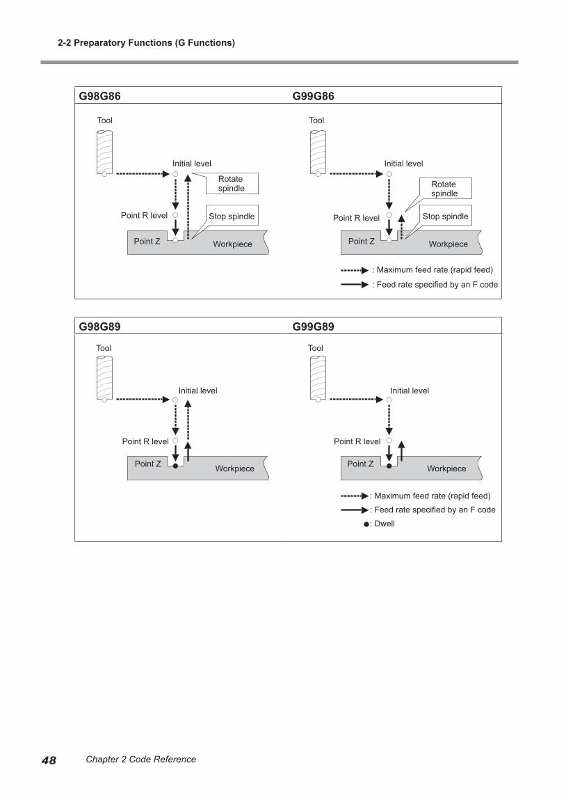
G98G86 G99G86
G98G89 G99G89
Tool
Initial level
Point R level
Point Z Workpiece
Tool
Initial level
Point R level
Point Z Workpiece
Stop spindle
Rotate spindle
Rotate spindle
Stop spindle
: Maximum feed rate (rapid feed)
: Feed rate specified by an F code
Tool
Initial level
Point R level
Point Z Workpiece
Tool
Initial level
Point R level
Point Z Workpiece
: Maximum feed rate (rapid feed)
: Feed rate specified by an F code
: Dwell
2-2 Preparatory Functions (G Functions)
49Chapter 2 Code Reference
G90 and G91 <Absolute and Incremental>
Format
G90G91
Description
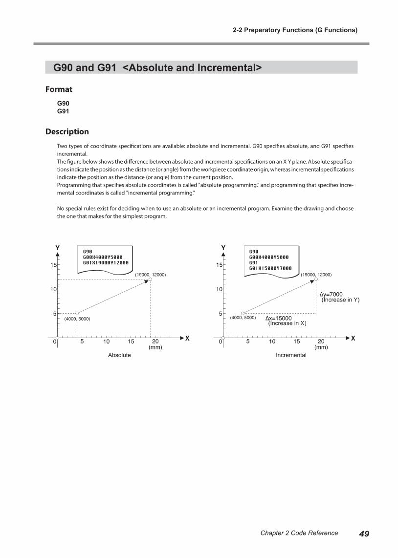
Two types of coordinate specifications are available: absolute and incremental. G90 specifies absolute, and G91 specifies incremental.The figure below shows the difference between absolute and incremental specifications on an X-Y plane. Absolute specifica-tions indicate the position as the distance (or angle) from the workpiece coordinate origin, whereas incremental specifications indicate the position as the distance (or angle) from the current position.Programming that specifies absolute coordinates is called "absolute programming," and programming that specifies incre-mental coordinates is called "incremental programming."
No special rules exist for deciding when to use an absolute or an incremental program. Examine the drawing and choose the one that makes for the simplest program.
Absolute Incremental
(Increase in X)
(Increase in Y)
2-2 Preparatory Functions (G Functions)
50 Chapter 2 Code Reference
G92 <Coordinate System>
Format
G92[X x][Y y][Z z][A a]
Parameter Function Acceptable range Effective range
x X-axis workpiece coor-dinate Range 1 Maximum cutting area
y Y-axis workpiece coordi-nate Range 1 Maximum cutting area
z Z-axis workpiece coor-dinate Range 1 Maximum cutting area
a A-axis workpiece coordi-nate (angle)
Dependent on machine specifications Maximum cutting area
Description
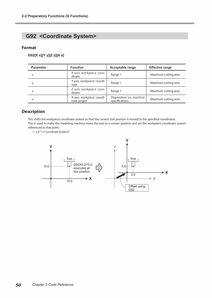
This shifts the workpiece coordinate system so that the current tool position is moved to the specified coordinates.This is used to make the modeling machine move the tool to a certain position and set the workpiece coordinate system referenced to that point. p.8 "1-2 Coordinate Systems"
Tool Tool
G92X5.0Y5.0 executed at this position
Offset using G92
2-2 Preparatory Functions (G Functions)
51Chapter 2 Code Reference
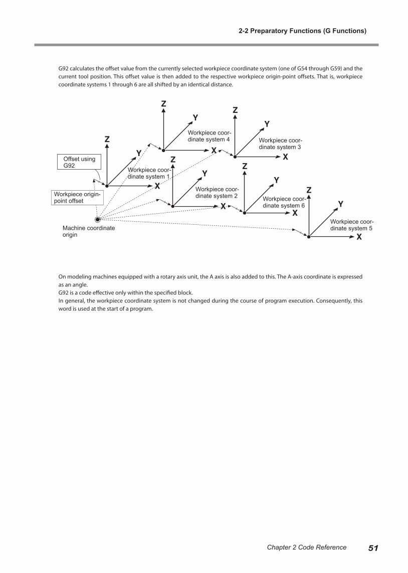
G92 calculates the offset value from the currently selected workpiece coordinate system (one of G54 through G59) and the current tool position. This offset value is then added to the respective workpiece origin-point offsets. That is, workpiece coordinate systems 1 through 6 are all shifted by an identical distance.
On modeling machines equipped with a rotary axis unit, the A axis is also added to this. The A-axis coordinate is expressed as an angle.G92 is a code effective only within the specified block.In general, the workpiece coordinate system is not changed during the course of program execution. Consequently, this word is used at the start of a program.
Offset using G92
Workpiece origin-point offset
Workpiece coor-dinate system 1
Workpiece coor-dinate system 4 Workpiece coor-
dinate system 3
Workpiece coor-dinate system 2 Workpiece coor-
dinate system 6
Workpiece coor-dinate system 5Machine coordinate
origin

2-2 Preparatory Functions (G Functions)
52 Chapter 2 Code Reference
G98 <Initial Level Return>
Format
G98
Description
This specifies the tool position (along the Z axis) after the completion of a fixed cycle. G98 signifies a return to the initial level. The initial level is the Z-axis tool position in effect before the fixed cycle was executed. For more information about fixed cycles, refer to "G80, G81, G82, G83, G85, G86, and G89 -- Fixed Cycle (Canned Cycle)."
G99 <Point R Level Return>
Format
G99
Description
This specifies the tool position (along the Z axis) after the completion of a fixed cycle. G99 signifies a return to the point R level. The point R level is set between the surface of the workpiece and the initial level. The point R level is used to increase the amount of tool movement at maximum speed and reduce the cutting time. For more information about fixed cycles, refer to "G80, G81, G82, G83, G85, G86, and G89 -- Fixed Cycle (Canned Cycle)."
Tool
Initial level
Point R level
Point Z Workpiece
Tool
Initial level
Point R level
Point Z Workpiece
2-3 Miscellaneous Functions (M Functions)
M00 <Program Stop>
Format
M00
Description
This pauses the program at the block specified by M00. The state of the spindle motor (rotating or stopped) does not change. Release of the paused state is to be performed on the modeling machine.Specify this code in a block by itself. Never include any other words in the same block.
M01 <Optional Stop>
Format
M01
Description
As with M00, the setting (enable or disable) can be made on the modeling machine. When set to "disabled," this instruction is ignored.Use this code in a block by itself. Never include any other words in the same block.
For information on how to make the setting, refer to the documentation for the modeling machine.
M02 <End of Program>
Format
M02
Description
This indicates that the program has ended. Be sure to specify M02 or M30 at the end of the program.Specify this code in a block by itself. Never include any other words in the same block.
53Chapter 2 Code Reference
M03 and M05 <Spindle Motor Start/Stop>
Format
M03M05
Description
M03 instructs the modeling machine to start rotation of the spindle, and M05 instructs the machine to stop it.M03 is the only instruction that is available to start the spindle motor. Cutting instructions such as G01, G02, and G03 do not include a function for starting rotation of the spindle, so M03 must be given to start spindle rotation before any such instruction is executed.If the spindle is already turning, M03 is ignored and the spindle continues to rotate. Similarly, M05 is ignored when the spindle motor is already stopped, and the spindle remains stopped.
M06 <Tool Selection>
Format
M06T number
Parameter Function Acceptable range Effective range
number stocker number Dependent on machine specification
Dependent on machine specification
Description
This sends a tool-selection instruction to the ATC (Auto Tool Changer). The stocker loaded with the tool to grasp is specified with T number. The value for number is given as a numerical value of 1 or higher, with no decimal point.Giving a value of 0 (zero) for number returns the currently grasped tool to the stocker. When 0 is specified at a time when no tool is grasped, the value is ignored. Any instruction to select a tool that is already grasped is also ignored.
M06T1 Select tool in stocker No. 1M06T0 Return the currently grasped tool
M06 has no tool-length offset function. To perform tool-length offset, G49 must be specified separately.M06 specifies only the stocker number. It does not directly specify the tool itself.Never put more than one M06 or T number in a single block. Also, be sure to specify M06 and the T number together, as a pair. Specifying one or the other alone results in an error.This function is valid only on modeling machines equipped with an ATC.
2-3 Miscellaneous Functions (M Functions)
54 Chapter 2 Code Reference
M12 and M13 <Air Blower On/Off>
Format
M12M13
Description
M12 instructs the modeling machine to turn on the air blower, and M13 instructs the machine to turn it off. This instruction is valid only on modeling machines equipped with an air blower.
M14 and M15 <Chip Cleaner On/Off>
Format
M14M15
Description
M14 instructs the modeling machine to turn on the chip cleaner, and M15 instructs the machine to turn it off. This instruction is valid only on modeling machines equipped with a chip cleaner.
M16 and M17 <Light On/Off>
Format
M16M17
Description
M16 instructs the modeling machine to turn on the illumination, and M17 instructs the machine to turn it off. This instruction is valid only on modeling machines equipped with illumination.
M30 <End of Program>
Format
M30
Description
This indicates that the program has ended. Be sure to specify M02 or M30 at the end of the program.Specify this code in a block by itself. Never include any other words in the same block.
2-3 Miscellaneous Functions (M Functions)
55Chapter 2 Code Reference
2-4 Spindle Speed Function (S Function)
S <Spindle Speed>
This specifies the speed of rotation of the spindle.Note that this has no function for starting rotation of the spindle. To rotate the spindle, an M03 code must be specified separately. p.54 "M03 and M05 <Spindle Motor Start/Stop>"
Format
S revolution speed
Parameter Function Acceptable range Effective range
revolution speed Spindle speed Range 2 Dependent on machine specification
Description
If this is specified when the spindle motor is already rotating, the operation is performed simultaneously with the specifica-tion. If this is specified when the spindle is stopped, the spindle rotates at the speed specified by the S function when M03 is given.Two methods of specifying the speed are available: "rpm" and "numerical code."
rpm SpecificationThis method specifies the speed in rpm (revolutions per minute). When the value specified is 100 or higher, it is interpreted as rpm. The numerical value is given with no decimal point.When a value exceeding the modeling machine's maximum speed is specified, the maximum speed is used; when a value less than the minimum speed is specified, the minimum speed is used.
Numerical-code SpecificationWhen the value is from 00 to 99, it is interpreted as a numerical-code specification. The numerical value is given with no decimal point.Speeds are preassigned to the numerical codes. To view the correspondences between numerical codes and assigned speeds, refer to the following page.When a value exceeding the modeling machine's maximum speed is specified, the maximum speed is used; when a value less than the minimum speed is specified, the minimum speed is used.
56 Chapter 2 Code Reference
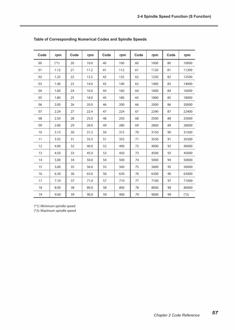
Table of Corresponding Numerical Codes and Spindle Speeds
Code rpm Code rpm Code rpm Code rpm Code rpm
00 (*1) 20 10.0 40 100 60 1000 80 10000
01 1.12 21 11.2 41 112 61 1120 81 11200
02 1.25 22 12.5 42 125 62 1250 82 12500
03 1.40 23 14.0 43 140 63 1400 83 14000
04 1.60 24 16.0 44 160 64 1600 84 16000
05 1.80 25 18.0 45 180 65 1800 85 18000
06 2.00 26 20.0 46 200 66 2000 86 20000
07 2.24 27 22.4 47 224 67 2240 87 22400
08 2.50 28 25.0 48 250 68 2500 88 25000
09 2.80 29 28.0 49 280 69 2800 89 28000
10 3.15 30 31.5 50 315 70 3150 90 31500
11 3.55 31 35.5 51 355 71 3550 91 35500
12 4.00 32 40.0 52 400 72 4000 92 40000
13 4.50 33 45.0 53 450 73 4500 93 45000
14 5.00 34 50.0 54 500 74 5000 94 50000
15 5.60 35 56.0 55 560 75 5600 95 56000
16 6.30 36 63.0 56 630 76 6300 96 63000
17 7.10 37 71.0 57 710 77 7100 97 71000
18 8.00 38 80.0 58 800 78 8000 98 80000
19 9.00 39 90.0 59 900 79 9000 99 (*2)
(*1): Minimum spindle speed(*2): Maximum spindle speed
2-4 Spindle Speed Function (S Function)
57Chapter 2 Code Reference

2-5 Feed Function (F Function)
F <Feed Rate>
This specifies the feed rate.
Format
F feed rate
Parameter Function Acceptable range Effective range
feed rate Feed rate Range 1 Dependent on machine specifications
Description
The feed rate is given as a numerical value placed immediately after the F. When an F function is specified, the function is performed simultaneously with the specification.
Examples of millimeter inputF120.0 Feed rate of 120 mm/min. (in mm/min. units)F120000 Feed rate of 120 mm/min. (in 0.001-mm/min. units)
Examples of inch inputF5.0 Feed rate of 5 inches/min. (in inches/min. units)F50000 Feed rate of 5 inches/min. (in 0.0001-inch/min. units)
If a feed rate exceeding the maximum is specified, the maximum feed rate is set. In the same way, the minimum feed rate is set if the specified feed rate is less than the minimum. Also, adjusting the feed rate to a value finer than the minimum resolution is impossible.
On modeling machines equipped with a rotary axis unit, the A-axis feed rate also follows the specification of the F code. As with the feed rates for the X, Y, and Z axes, this is specified as millimeters (or inches) per minute. The speed of rotation is not specified directly. The A-axis feed rate varies according to the tool position at the time when the command for A-axis feed is encountered. The peripheral speed for the circle whose radius is the distance from the Y and Z coordinates of the tool position to the origin is the feed rate specified by the F code. The following figure shows a case where the Y- and Z-axis origins are set at the A-axis center of rotation.
Tool
A-axis feed rate (mm/min. or inch/min.)
A-axis center of rotation
58 Chapter 2 Code Reference
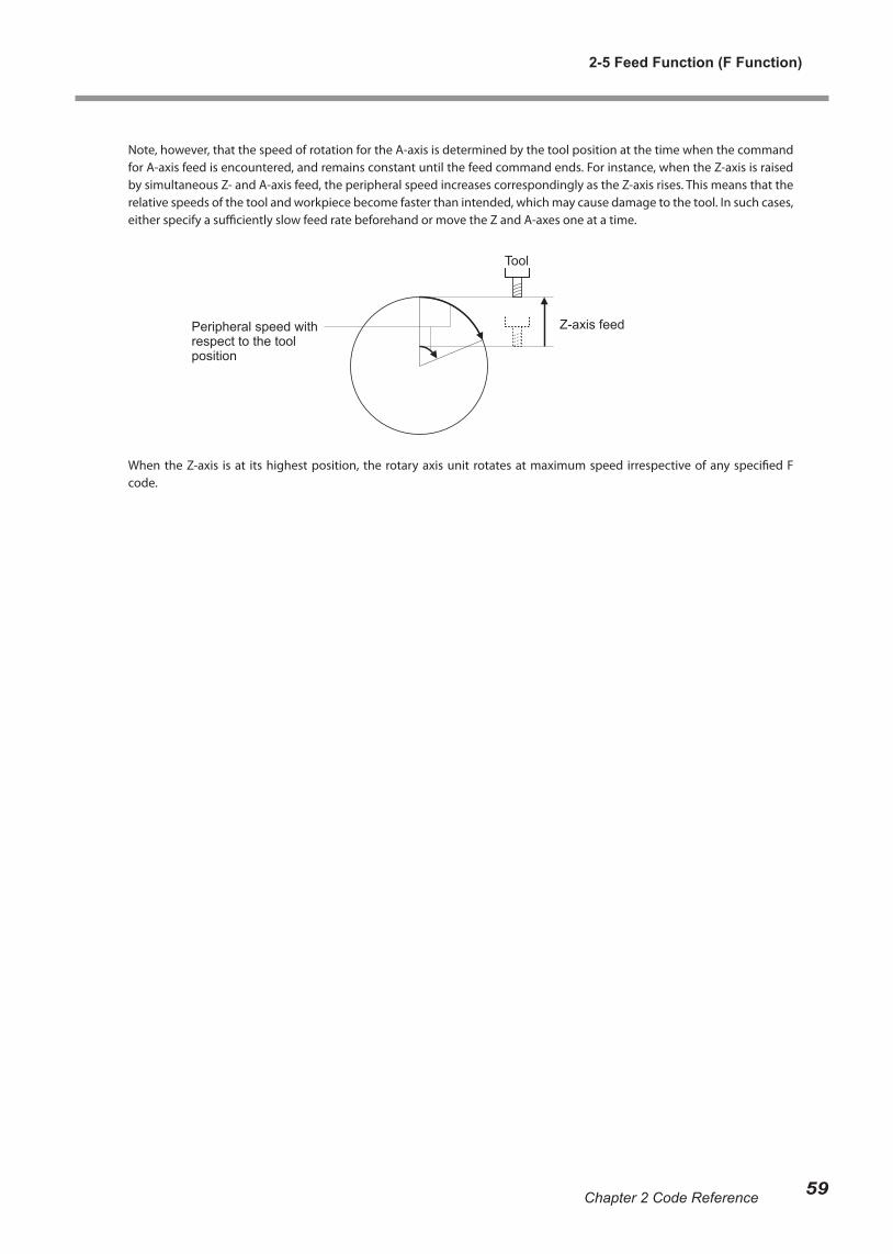
Note, however, that the speed of rotation for the A-axis is determined by the tool position at the time when the command for A-axis feed is encountered, and remains constant until the feed command ends. For instance, when the Z-axis is raised by simultaneous Z- and A-axis feed, the peripheral speed increases correspondingly as the Z-axis rises. This means that the relative speeds of the tool and workpiece become faster than intended, which may cause damage to the tool. In such cases, either specify a sufficiently slow feed rate beforehand or move the Z and A-axes one at a time.
When the Z-axis is at its highest position, the rotary axis unit rotates at maximum speed irrespective of any specified F code.
Tool
Z-axis feedPeripheral speed with respect to the tool position
2-5 Feed Function (F Function)
59Chapter 2 Code Reference
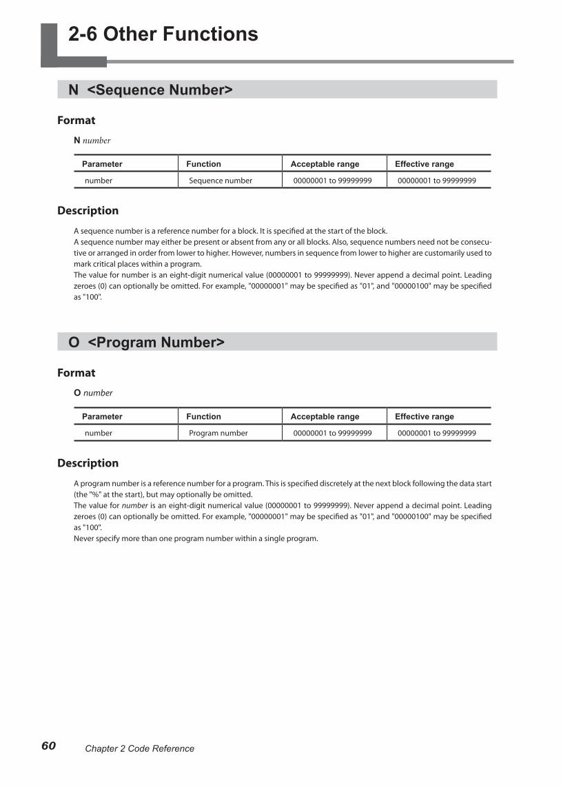
2-6 Other Functions
N <Sequence Number>
Format
N number
Parameter Function Acceptable range Effective range
number Sequence number 00000001 to 99999999 00000001 to 99999999
Description
A sequence number is a reference number for a block. It is specified at the start of the block.A sequence number may either be present or absent from any or all blocks. Also, sequence numbers need not be consecu-tive or arranged in order from lower to higher. However, numbers in sequence from lower to higher are customarily used to mark critical places within a program.The value for number is an eight-digit numerical value (00000001 to 99999999). Never append a decimal point. Leading zeroes (0) can optionally be omitted. For example, "00000001" may be specified as "01", and "00000100" may be specified as "100".
O <Program Number>
Format
O number
Parameter Function Acceptable range Effective range
number Program number 00000001 to 99999999 00000001 to 99999999
Description
A program number is a reference number for a program. This is specified discretely at the next block following the data start (the "%" at the start), but may optionally be omitted.The value for number is an eight-digit numerical value (00000001 to 99999999). Never append a decimal point. Leading zeroes (0) can optionally be omitted. For example, "00000001" may be specified as "01", and "00000100" may be specified as "100".Never specify more than one program number within a single program.
60 Chapter 2 Code Reference
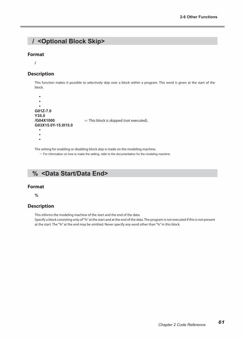
/ <Optional Block Skip>
Format
/
Description
This function makes it possible to selectively skip over a block within a program. This word is given at the start of the block.
• • •G01Z-7.0Y35.0/G04X1000 <- This block is skipped (not executed).G03X15.0Y-15.0I15.0 • • •
The setting for enabling or disabling block skip is made on the modeling machine. For information on how to make the setting, refer to the documentation for the modeling machine.
% <Data Start/Data End>
Format
%
Description
This informs the modeling machine of the start and the end of the data. Specify a block consisting only of “%” at the start and at the end of the data. The program is not executed if this is not present at the start. The “%” at the end may be omitted. Never specify any word other than “%” in this block.
2-6 Other Functions
61Chapter 2 Code Reference
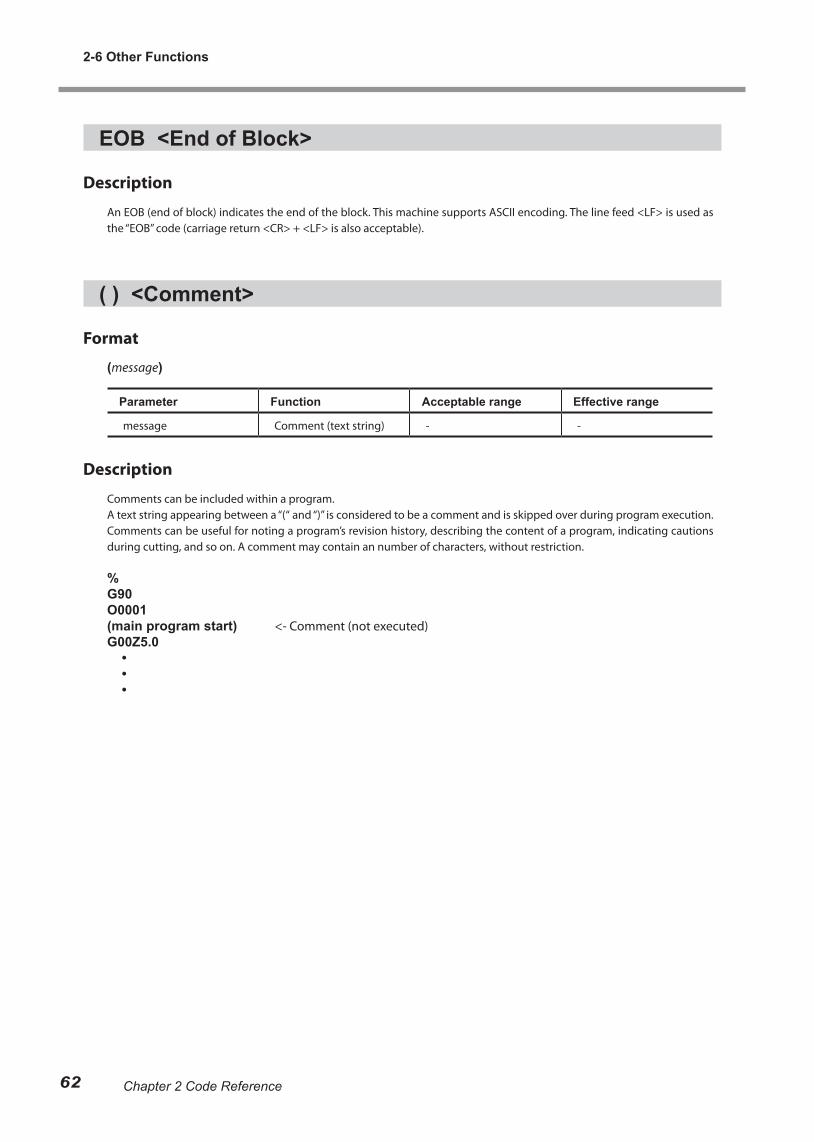
EOB <End of Block>
Description
An EOB (end of block) indicates the end of the block. This machine supports ASCII encoding. The line feed <LF> is used as the “EOB” code (carriage return <CR> + <LF> is also acceptable).
( ) <Comment>
Format
(message)
Parameter Function Acceptable range Effective range
message Comment (text string) - -
Description
Comments can be included within a program.A text string appearing between a “(“ and “)” is considered to be a comment and is skipped over during program execution. Comments can be useful for noting a program’s revision history, describing the content of a program, indicating cautions during cutting, and so on. A comment may contain an number of characters, without restriction.
%G90O0001(main program start) <- Comment (not executed)G00Z5.0 • • •
2-6 Other Functions
62 Chapter 2 Code Reference
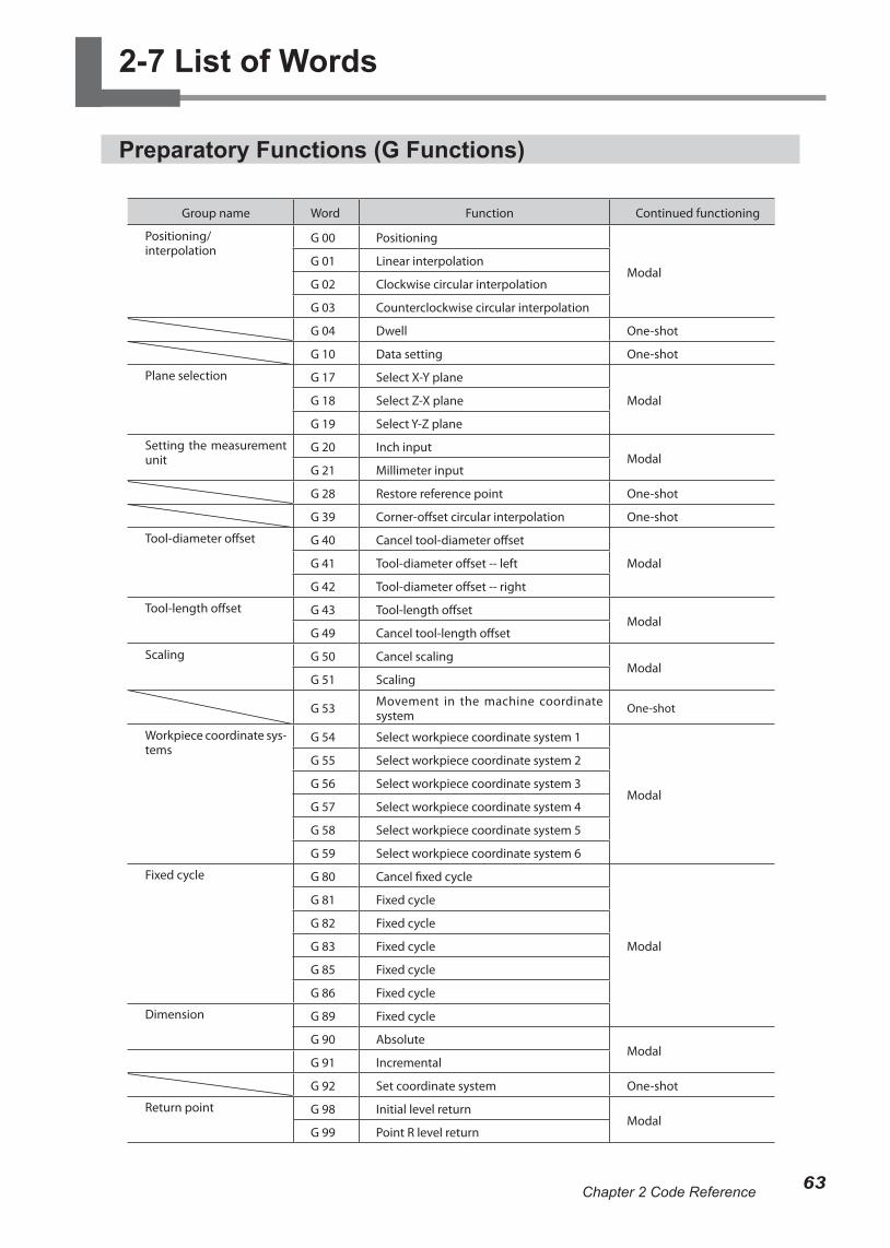
2-7 List of Words
Preparatory Functions (G Functions)
Group name Word Function Continued functioning
Positioning/interpolation
G 00 Positioning
ModalG 01 Linear interpolation
G 02 Clockwise circular interpolation
G 03 Counterclockwise circular interpolation
G 04 Dwell One-shot
G 10 Data setting One-shot
Plane selection G 17 Select X-Y plane
ModalG 18 Select Z-X plane
G 19 Select Y-Z plane
Setting the measurement unit
G 20 Inch inputModal
G 21 Millimeter input
G 28 Restore reference point One-shot
G 39 Corner-offset circular interpolation One-shot
Tool-diameter offset G 40 Cancel tool-diameter offset
ModalG 41 Tool-diameter offset -- left
G 42 Tool-diameter offset -- right
Tool-length offset G 43 Tool-length offsetModal
G 49 Cancel tool-length offset
Scaling G 50 Cancel scalingModal
G 51 Scaling
G 53 Movement in the machine coordinate system One-shot
Workpiece coordinate sys-tems
G 54 Select workpiece coordinate system 1
Modal
G 55 Select workpiece coordinate system 2
G 56 Select workpiece coordinate system 3
G 57 Select workpiece coordinate system 4
G 58 Select workpiece coordinate system 5
G 59 Select workpiece coordinate system 6
Fixed cycle G 80 Cancel fixed cycle
Modal
G 81 Fixed cycle
G 82 Fixed cycle
G 83 Fixed cycle
G 85 Fixed cycle
G 86 Fixed cycle
Dimension G 89 Fixed cycle
G 90 AbsoluteModal
G 91 Incremental
G 92 Set coordinate system One-shot
Return point G 98 Initial level returnModal
G 99 Point R level return
63Chapter 2 Code Reference
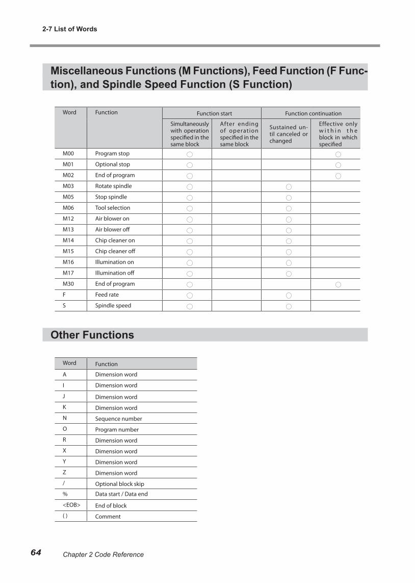
Miscellaneous Functions (M Functions), Feed Function (F Func-tion), and Spindle Speed Function (S Function)
Word Function Function start Function continuation
Simultaneously with operation specified in the same block
After ending of operation specified in the same block
Sustained un-til canceled or changed
Effective only w i t h i n t h e block in which specified
M00 Program stop
M01 Optional stop
M02 End of program
M03 Rotate spindle
M05 Stop spindle
M06 Tool selection
M12 Air blower on
M13 Air blower off
M14 Chip cleaner on
M15 Chip cleaner off
M16 Illumination on
M17 Illumination off
M30 End of program
F Feed rate
S Spindle speed
Other Functions
Word Function
A Dimension word
I Dimension word
J Dimension word
K Dimension word
N Sequence number
O Program number
R Dimension word
X Dimension word
Y Dimension word
Z Dimension word
/ Optional block skip
% Data start / Data end
<EOB> End of block
( ) Comment
2-7 List of Words
64 Chapter 2 Code Reference

65


R2-090612