nc configurator2 instruction · pdf file4.9 system configuration management ... 1.1 outline of...
TRANSCRIPT

Introduction
This instruction manual describes how to use NC Configurator2. Incorrect handling may lead to unforeseen accidents, so make sure to read this instruction manual thoroughly before operation to ensure correct usage.NC Configurator2 supports the following NC series.
Screens under development are included in this manual. So the screens used in this manual might differ slightly from the actual screens.
Notes on Reading This Manual
(1) This manual describes as many special operations as possible, but it should be kept in mind that operations not mentioned in this manual cannot be performed.
(2) For the specifications of individual machine tools, refer to the manuals issued by the respective machine tool builders. The "restrictions" and "available functions" described by the machine tool builders have precedence over this manual.
Written as in this manual Appropriate NCM7 series M70/M70V/M700/M700V seriesE70 series E70 seriesC70 C70M60/M60S series M60/M60S series and E60/E68


Precautions for Safety
Always read the specifications issued by the machine tool builder, this manual, related manuals and attached documents before installation, operation, programming, maintenance or inspection to ensure correct use. Understand this numerical controller, safety items and cautions before using the unit. This manual ranks the safety precautions into "DANGER", "WARNING" and "CAUTION".
Note that even items ranked as " CAUTION", may lead to major results depending on the situation. In any case, important information that must always be observed is described.
The following signs indicate prohibition and compulsory.
The meaning of each pictorial sign is as follows.
Not applicable in this manual.
Not applicable in this manual.
When the user may be subject to imminent fatalities or major injuries if handling is mistaken.
When the user may be subject to fatalities or major injuries if handling is mistaken.
When the user may be subject to injuries or when physical damage may occur if handling is mistaken.
This sign indicates prohibited behavior (must not do).
For example, indicates "Keep fire away".
This sign indicates a thing that is compulsory (must do).
For example, indicates "it must be grounded".
CAUTION
CAUTION
rotated object
CAUTION
HOT
Danger
Electric shock risk
Danger
explosive
Prohibited
Disassembly is
prohibited
KEEP FIRE AWAY
General instruction
Earth ground
DANGER
WARNING
CAUTION
DANGER
WARNING

1. Items related to operation
Items not described in this manual must be interpreted as "not possible".
This manual is written on the assumption that all functions are added.
Some screens and functions may differ depending on the NC system (or its version), and some functions may not be possible.
Incorrect parameter settings may cause unforeseen machine operations.To change parameters, fully confirm the meaning of the parameters.
CAUTION

Trademarks MELDAS, MELSEC, EZSocket, EZMotion, iQ Platform, MELSOFT, GOT, CC-Link, CC-Link/LT and CC-Link
IE are either trademarks or registered trademarks of Mitsubishi Electric Corporation in Japan and/or other
countries.
Ethernet is a registered trademark of Xerox Corporation in the United States and/or other countries.
Microsoft® and Windows® are either trademarks or registered trademarks of Microsoft Corporation in the
United States and/or other countries.
CompactFlash and CF are either trademarks or registered trademarks of SanDisk Corporation in the United
States and/or other countries.
UNIX is a registered trademark of The Open Group in the United States and/or other countries.
Intel® and Pentium® are either trademarks or registered trademarks of Intel Corporation in the United States
and/or other countries.
Other company and product names that appear in this manual are trademarks or registered trademarks of the
respective companies.


CONTENTS
1 Outline........................................................................................................................................................... 11.1 Outline of NC Configurator2................................................................................................................... 21.2 Outline of Functions ............................................................................................................................... 21.3 System Requirements............................................................................................................................ 21.4 Connection Configuration ...................................................................................................................... 3
2 Installation and Setup.................................................................................................................................. 52.1 Preparation for PC side.......................................................................................................................... 62.2 Installation Procedure ............................................................................................................................ 6
2.2.1 First Time Installation Procedure ................................................................................................... 62.2.2 Upgradeing Procedure................................................................................................................... 9
2.3 Uninstall Procedure.............................................................................................................................. 102.3.1 Uninstall from the Control Panel .................................................................................................. 102.3.2 Uninstall by Double-clicking on Setup.exe................................................................................... 11
3 Operation Procedure ................................................................................................................................. 133.1 Start NC Configurator2 ........................................................................................................................ 143.2 Operation Flow..................................................................................................................................... 153.3 Project File ........................................................................................................................................... 163.4 Explanation of the Screen.................................................................................................................... 16
3.4.1 Screen Configuration ................................................................................................................... 163.4.2 Menu Configuration...................................................................................................................... 173.4.3 Tab............................................................................................................................................... 19
4 Basic Operation.......................................................................................................................................... 214.1 File Function ........................................................................................................................................ 22
4.1.1 Create a New Project................................................................................................................... 224.1.1.1 Create a New Project (with Initial Setting) ........................................................................... 224.1.1.2 Create a New Project (without Initial Setting) ...................................................................... 23
4.1.2 Open an Existing File................................................................................................................... 244.1.3 Open an Online Project................................................................................................................ 254.1.4 Saving a Project........................................................................................................................... 274.1.5 Importing NC Data ....................................................................................................................... 284.1.6 Exporting the NC Parameters ...................................................................................................... 304.1.7 Output NC Parameter (csv file format)......................................................................................... 314.1.8 Print ............................................................................................................................................. 32
4.2 Machine Information Management ...................................................................................................... 334.3 Parameter Management ...................................................................................................................... 34
4.3.1 M7/E70 Series Parameters.......................................................................................................... 354.3.2 C70 Series Parameters................................................................................................................ 374.3.3 M60/M60S Series Parameters..................................................................................................... 394.3.4 Parameter Search........................................................................................................................ 404.3.5 Parameter Modification History.................................................................................................... 404.3.6 Parameter Conversion ................................................................................................................. 414.3.7 Parameter Comparison................................................................................................................ 43
4.4 Tool Life Data Management................................................................................................................. 444.5 Tool Compensation Data Management ............................................................................................... 454.6 Common Variable Data Management.................................................................................................. 464.7 Workpiece Offset Data Management................................................................................................... 464.8 Machining Program Management........................................................................................................ 474.9 System Configuration Management..................................................................................................... 484.10 Project Management.......................................................................................................................... 484.11 Read and Write the NC Data ............................................................................................................. 49
4.11.1 Read From NC........................................................................................................................... 504.11.2 Write To NC ............................................................................................................................... 51
4.12 Function Parameter ........................................................................................................................... 524.12.1 High-speed High-accuracy (M7 series)...................................................................................... 524.12.2 Machining Condition Selection I (M7 series).............................................................................. 53
4.12.3 Soft Limit (M7/E70 series, C70) ................................................................................................. 544.12.4 Thread Cutting (M7/E70 series)................................................................................................. 55
4.13 Adjustment Function .......................................................................................................................... 564.13.1 Roundness (M60/M60S series) ................................................................................................. 564.13.2 High-speed High-accuracy (M60/M60S series) ......................................................................... 584.13.3 Servo Adjustment (M60/M60S series) ....................................................................................... 59
4.14 Wizard Function ................................................................................................................................. 624.14.1 Parameter Initial Setting............................................................................................................. 62
5 Standard RS232C Communication & Tape Mode ................................................................................... 675.1 Tape Mode........................................................................................................................................... 685.2 Standard RS232C Communication ...................................................................................................... 69
5.2.1 Sending Text................................................................................................................................ 695.2.2 Receiving Text ............................................................................................................................. 70
Appendix 1 Registration after installation .................................................................................................. 71Appendix 1.1 Registration after installation................................................................................................ 72
Appendix 2 Restrictions ............................................................................................................................... 73Appendix 2.1 Restrictions .......................................................................................................................... 74
Appendix 3 List of Error Messages ............................................................................................................. 77Appendix 3.1 List of Error Messages ......................................................................................................... 78

1
1Outline
1 OutlineMITSUBISHI CNC
2
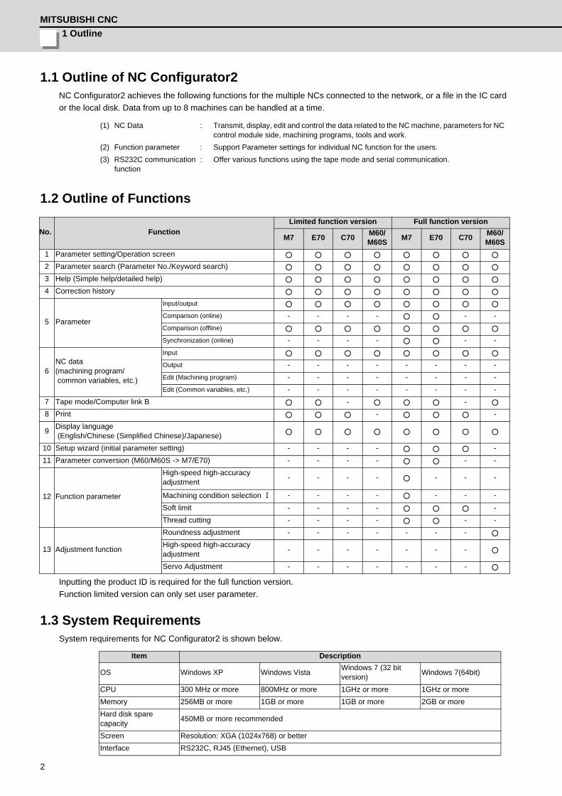
1.1 Outline of NC Configurator2NC Configurator2 achieves the following functions for the multiple NCs connected to the network, or a file in the IC card or the local disk. Data from up to 8 machines can be handled at a time.
1.2 Outline of Functions
Inputting the product ID is required for the full function version.Function limited version can only set user parameter.
1.3 System RequirementsSystem requirements for NC Configurator2 is shown below.
(1) NC Data : Transmit, display, edit and control the data related to the NC machine, parameters for NC control module side, machining programs, tools and work.
(2) Function parameter : Support Parameter settings for individual NC function for the users.(3) RS232C communication
function: Offer various functions using the tape mode and serial communication.
No. FunctionLimited function version Full function version
M7 E70 C70 M60/M60S M7 E70 C70 M60/
M60S1 Parameter setting/Operation screen ○ ○ ○ ○ ○ ○ ○ ○
2 Parameter search (Parameter No./Keyword search) ○ ○ ○ ○ ○ ○ ○ ○
3 Help (Simple help/detailed help) ○ ○ ○ ○ ○ ○ ○ ○
4 Correction history ○ ○ ○ ○ ○ ○ ○ ○
5 Parameter
Input/output ○ ○ ○ ○ ○ ○ ○ ○
Comparison (online) - - - - ○ ○ - -Comparison (offline) ○ ○ ○ ○ ○ ○ ○ ○
Synchronization (online) - - - - ○ ○ - -
6NC data(machining program/ common variables, etc.)
Input ○ ○ ○ ○ ○ ○ ○ ○
Output - - - - - - - -Edit (Machining program) - - - - - - - -Edit (Common variables, etc.) - - - - - - - -
7 Tape mode/Computer link B ○ ○ - ○ ○ ○ - ○
8 Print ○ ○ ○ - ○ ○ ○ -
9 Display language (English/Chinese (Simplified Chinese)/Japanese) ○ ○ ○ ○ ○ ○ ○ ○
10 Setup wizard (initial parameter setting) - - - - ○ ○ ○ -11 Parameter conversion (M60/M60S -> M7/E70) - - - - ○ ○ - -
12 Function parameter
High-speed high-accuracy adjustment - - - - ○ - - -
Machining condition selection Ⅰ - - - - ○ - - -
Soft limit - - - - ○ ○ ○ -Thread cutting - - - - ○ ○ - -
13 Adjustment function
Roundness adjustment - - - - - - - ○
High-speed high-accuracy adjustment - - - - - - - ○
Servo Adjustment - - - - - - - ○
Item Description
OS Windows XP Windows Vista Windows 7 (32 bit version) Windows 7(64bit)
CPU 300 MHz or more 800MHz or more 1GHz or more 1GHz or moreMemory 256MB or more 1GB or more 1GB or more 2GB or moreHard disk spare capacity 450MB or more recommended
Screen Resolution: XGA (1024x768) or betterInterface RS232C, RJ45 (Ethernet), USB

NC Configurator2 Instruction Manual1.4 Connection Configuration
3
1.4 Connection ConfigurationConnection configuration is shown below.
NC Configurator2 (PC)
[Machine tool]
[CNC]
M700/M700V/M70/M70V/E70
<Ethernet>
<USB> NC Configurator2
USB-GOT(Q mode) USB-PLC CPU
NC Configurator2 (PC)
[Machine tool]
[CNC]
C70
M700/M700V/M70/M70V/E70
M60/M60S/ E60/E68
<RS232C>
C70

1 OutlineMITSUBISHI CNC
4

5
2Installation and Setup
2 Installation and SetupMITSUBISHI CNC
6
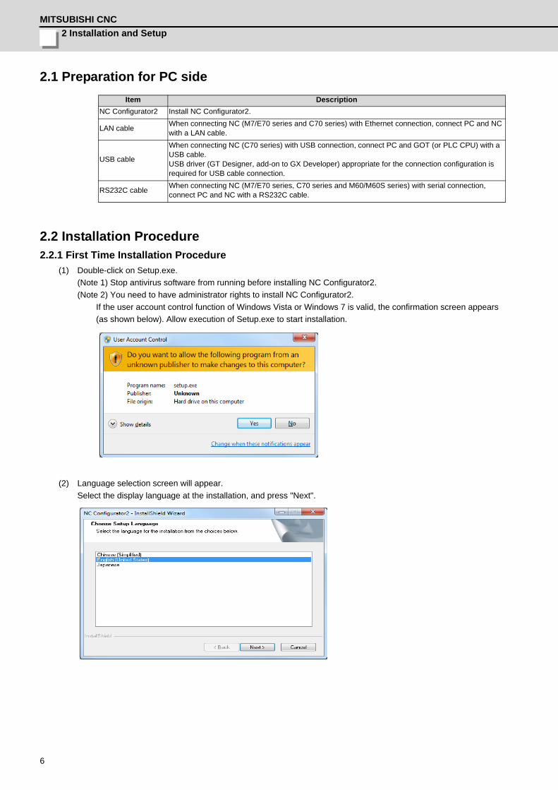
2.1 Preparation for PC side
2.2 Installation Procedure2.2.1 First Time Installation Procedure
(1) Double-click on Setup.exe. (Note 1) Stop antivirus software from running before installing NC Configurator2.(Note 2) You need to have administrator rights to install NC Configurator2.
If the user account control function of Windows Vista or Windows 7 is valid, the confirmation screen appears (as shown below). Allow execution of Setup.exe to start installation.
(2) Language selection screen will appear.Select the display language at the installation, and press "Next".
Item DescriptionNC Configurator2 Install NC Configurator2.
LAN cable When connecting NC (M7/E70 series and C70 series) with Ethernet connection, connect PC and NC with a LAN cable.
USB cable
When connecting NC (C70 series) with USB connection, connect PC and GOT (or PLC CPU) with a USB cable. USB driver (GT Designer, add-on to GX Developer) appropriate for the connection configuration is required for USB cable connection.
RS232C cable When connecting NC (M7/E70 series, C70 series and M60/M60S series) with serial connection, connect PC and NC with a RS232C cable.
NC Configurator2 Instruction Manual2.2 Installation Procedure
7
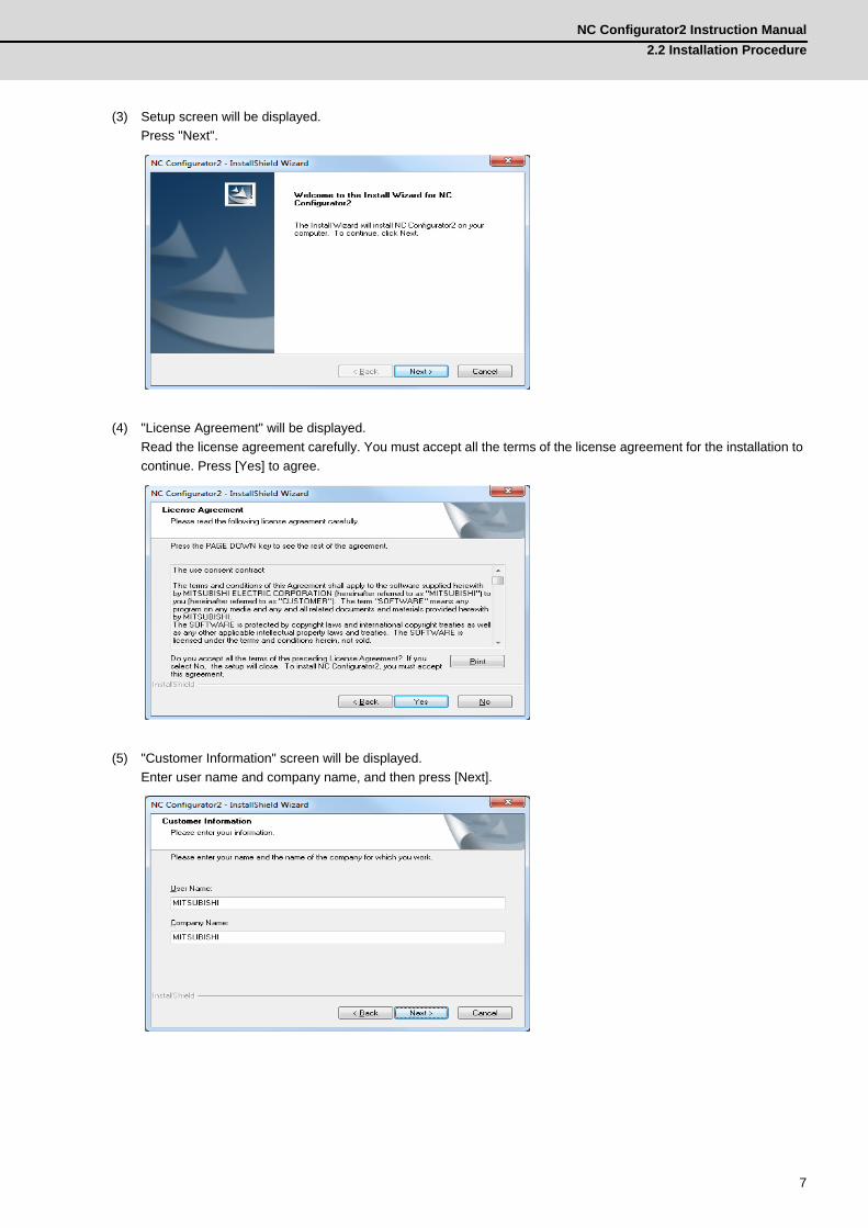
(3) Setup screen will be displayed. Press "Next".
(4) "License Agreement" will be displayed. Read the license agreement carefully. You must accept all the terms of the license agreement for the installation to continue. Press [Yes] to agree.
(5) "Customer Information" screen will be displayed. Enter user name and company name, and then press [Next].
2 Installation and SetupMITSUBISHI CNC
8
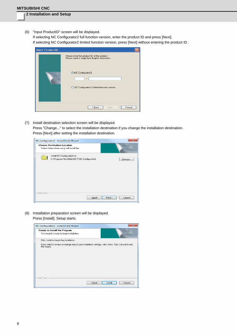
(6) "Input ProductID" screen will be displayed. If selecting NC Configurator2 full function version, enter the product ID and press [Next].If selecting NC Configurator2 limited function version, press [Next] without entering the product ID .
(7) Install destination selection screen will be displayed. Press "Change..." to select the installation destination if you change the installation destination. Press [Next] after setting the installation destination.
(8) Installation preparation screen will be displayed. Press [Install]. Setup starts.
NC Configurator2 Instruction Manual2.2 Installation Procedure
9
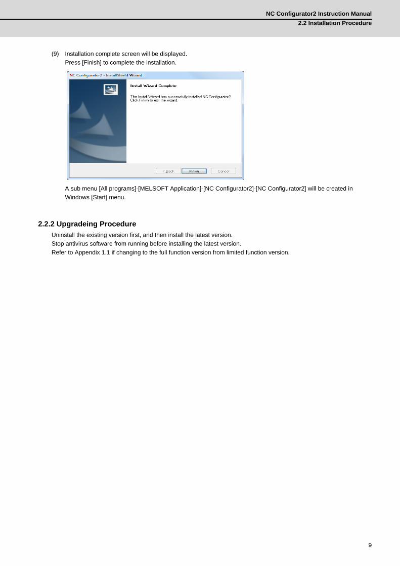
(9) Installation complete screen will be displayed. Press [Finish] to complete the installation.
A sub menu [All programs]-[MELSOFT Application]-[NC Configurator2]-[NC Configurator2] will be created in Windows [Start] menu.
2.2.2 Upgradeing ProcedureUninstall the existing version first, and then install the latest version.Stop antivirus software from running before installing the latest version.Refer to Appendix 1.1 if changing to the full function version from limited function version.
2 Installation and SetupMITSUBISHI CNC
10
2.3 Uninstall ProcedureThere are two ways to uninstall NC Configurator2; uninstall from Control Panels and the other is by double clicking on Setup.exe.
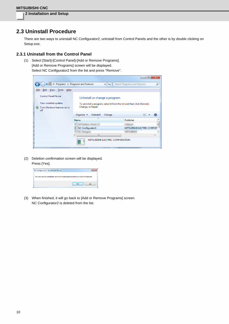
2.3.1 Uninstall from the Control Panel(1) Select [Start]-[Control Panel]-[Add or Remove Programs].
[Add or Remove Programs] screen will be displayed.Select NC Configurator2 from the list and press "Remove".
(2) Deletion confirmation screen will be displayed.Press [Yes].
(3) When finished, it will go back to [Add or Remove Programs] screen.NC Configurator2 is deleted from the list.
NC Configurator2 Instruction Manual2.3 Uninstall Procedure
11
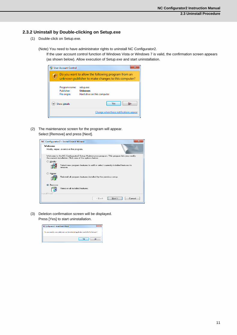
2.3.2 Uninstall by Double-clicking on Setup.exe(1) Double-click on Setup.exe.
(Note) You need to have administrator rights to uninstall NC Configurator2.If the user account control function of Windows Vista or Windows 7 is valid, the confirmation screen appears (as shown below). Allow execution of Setup.exe and start uninstallation.
(2) The maintenance screen for the program will appear.Select [Remove] and press [Next].
(3) Deletion confirmation screen will be displayed.Press [Yes] to start uninstallation.
2 Installation and SetupMITSUBISHI CNC
12
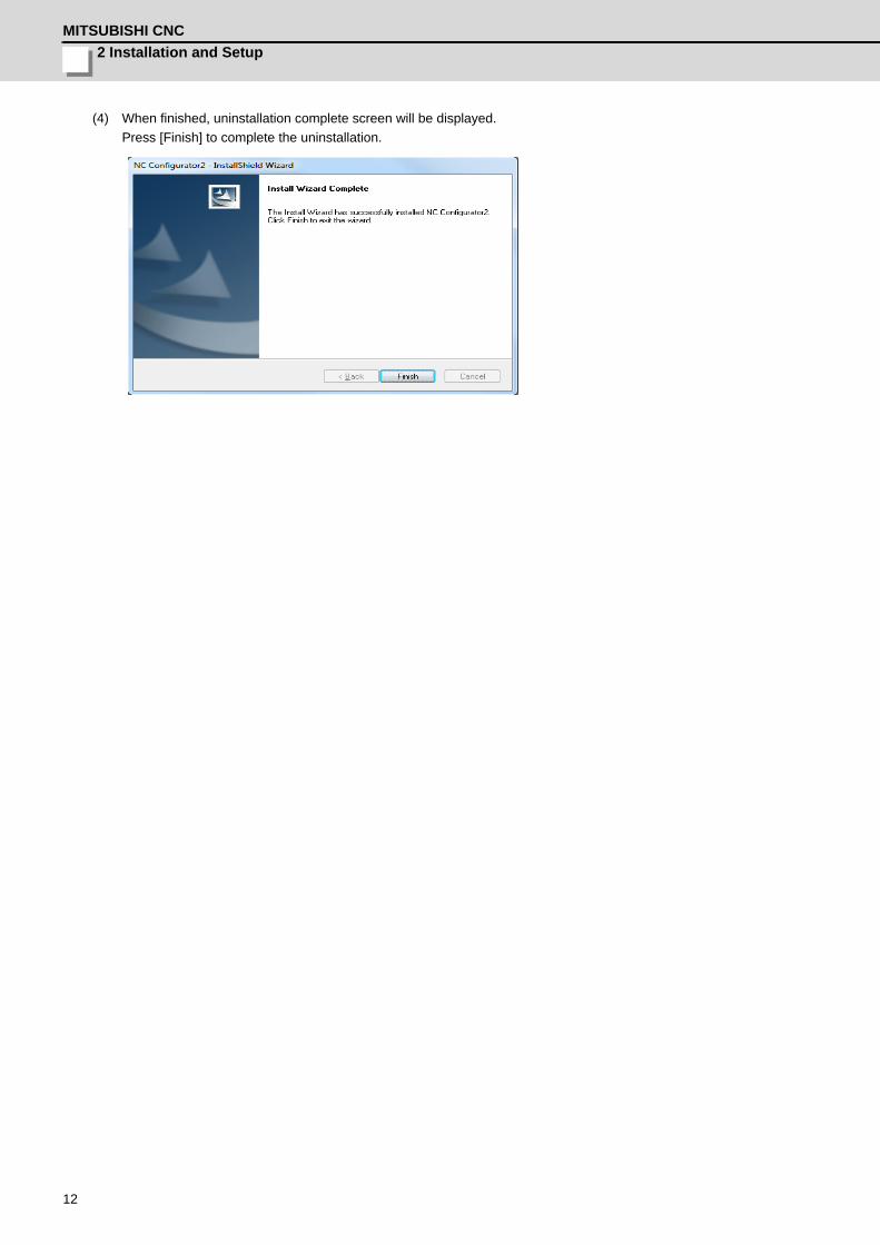
(4) When finished, uninstallation complete screen will be displayed.Press [Finish] to complete the uninstallation.

13
3Operation Procedure
3 Operation ProcedureMITSUBISHI CNC
14
3.1 Start NC Configurator2
(1) When NC Configurator2 is started Caps Lock will be ON automatically, and when it is finished Caps Lock will be OFF automatically.
Operation Method
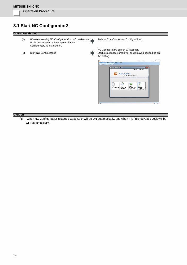
(1) When connecting NC Configurator2 to NC, make sure NC is connected to the computer that NC Configurator2 is installed on.
Refer to "1.4 Connection Configuration".
(2) Start NC Configurator2.NC Configurator2 screen will appear. Startup guidance screen will be displayed depending on the setting.
Caution
NC Configurator2 Instruction Manual3.2 Operation Flow
15
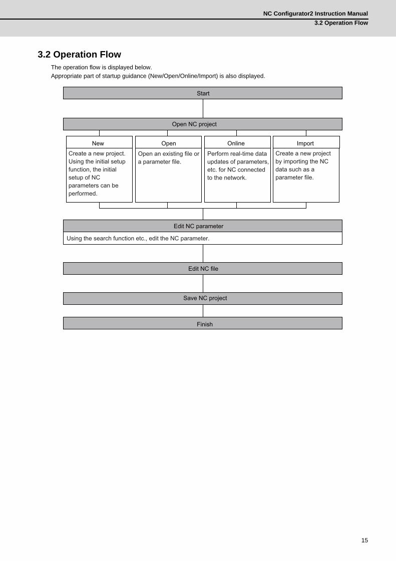
3.2 Operation FlowThe operation flow is displayed below.Appropriate part of startup guidance (New/Open/Online/Import) is also displayed.
New Open Import
Create a new project. Using the initial setup function, the initial setup of NC parameters can be performed.
Open an existing file or a parameter file.
Create a new project by importing the NC data such as a parameter file.
Start
Open NC project
Edit NC parameter
Edit NC file
Save NC project
Finish
Using the search function etc., edit the NC parameter.
Online
Perform real-time data updates of parameters, etc. for NC connected to the network.

3 Operation ProcedureMITSUBISHI CNC
16
3.3 Project FileThis tool manages data of NC such as parameter, machining program, work offset, system configuration and the machine tool related data with a dedicated project file (*.nc2).Reading NC Configurator project file (*.ncp) and inputting the NC related individual data, as well as outputting NC parameters, can also be performed.
3.4 Explanation of the Screen3.4.1 Screen Configuration
Screen
Display item Description(1) Menu bar Display menus which can be used with NC Configurator2.(2) Tool bar Display frequently used menu item as an icon.
(3) Navigation window Display NC Configurator2 project's data in tree format. Displayed items depend on NC model.
(4) Main screen Display the selected data with the navigation window. Set, print, and input/output data.(5) Tab Switch the operation screen for target data with tab.(6) Outline help Display the name of selected parameter.
(7) Parameter historyDisplay the modification history of parameter. Click on the history to display the appropriate parameter. Double-click on the history to select whether to restore the setting value.
(8) Help window Display the detailed help for the selected parameter.(9) Parameter Search Display the parameter related to the keyword.
(10) Status bar Display the status information such as CNC model name, connection state, and NC alarm/warning etc.
(1)
(2)
(3)
(5)
(8)
(4)
(6) (7) (10) (9)
NC Configurator2 Instruction Manual3.4 Explanation of the Screen
17
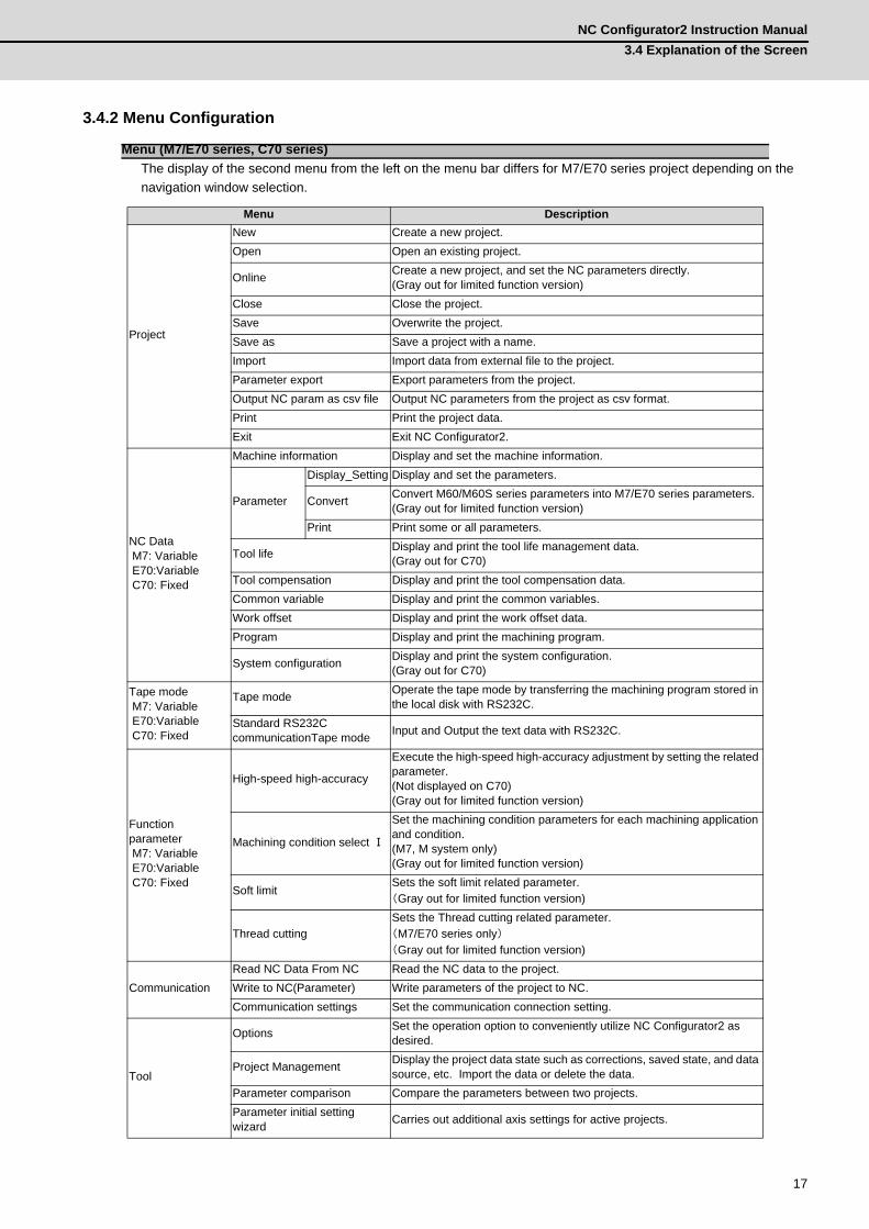
3.4.2 Menu Configuration
The display of the second menu from the left on the menu bar differs for M7/E70 series project depending on the navigation window selection.
Menu (M7/E70 series, C70 series)
Menu Description
Project
New Create a new project.Open Open an existing project.
Online Create a new project, and set the NC parameters directly.(Gray out for limited function version)
Close Close the project.Save Overwrite the project.Save as Save a project with a name.Import Import data from external file to the project.Parameter export Export parameters from the project.Output NC param as csv file Output NC parameters from the project as csv format.Print Print the project data.Exit Exit NC Configurator2.
NC Data M7: Variable E70:Variable C70: Fixed
Machine information Display and set the machine information.
Parameter
Display_Setting Display and set the parameters.
Convert Convert M60/M60S series parameters into M7/E70 series parameters.(Gray out for limited function version)
Print Print some or all parameters.
Tool life Display and print the tool life management data.(Gray out for C70)
Tool compensation Display and print the tool compensation data.Common variable Display and print the common variables.Work offset Display and print the work offset data.Program Display and print the machining program.
System configuration Display and print the system configuration.(Gray out for C70)
Tape mode M7: Variable E70:Variable C70: Fixed
Tape mode Operate the tape mode by transferring the machining program stored in the local disk with RS232C.
Standard RS232C communicationTape mode Input and Output the text data with RS232C.
Function parameter M7: Variable E70:Variable C70: Fixed
High-speed high-accuracy
Execute the high-speed high-accuracy adjustment by setting the related parameter.(Not displayed on C70)(Gray out for limited function version)
Machining condition select Ⅰ
Set the machining condition parameters for each machining application and condition. (M7, M system only)(Gray out for limited function version)
Soft limitSets the soft limit related parameter.
(Gray out for limited function version)
Thread cuttingSets the Thread cutting related parameter.
(M7/E70 series only)(Gray out for limited function version)
CommunicationRead NC Data From NC Read the NC data to the project.Write to NC(Parameter) Write parameters of the project to NC.Communication settings Set the communication connection setting.
Tool
Options Set the operation option to conveniently utilize NC Configurator2 as desired.
Project Management Display the project data state such as corrections, saved state, and data source, etc. Import the data or delete the data.
Parameter comparison Compare the parameters between two projects.Parameter initial setting wizard Carries out additional axis settings for active projects.
3 Operation ProcedureMITSUBISHI CNC
18
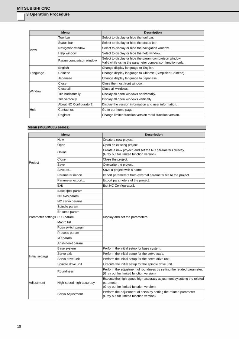
View
Tool bar Select to display or hide the tool bar.Status bar Select to display or hide the status bar.Navigation window Select to display or hide the navigation window.Help window Select to display or hide the help window.
Param comparison window Select to display or hide the param comparison window. Valid while using the parameter comparison function only.
LanguageEnglish Change display language to English.Chinese Change display language to Chinese (Simplified Chinese).Japanese Change display language to Japanese.
Window
Close Close the most front window.Close all Close all windows.Tile horizontally Display all open windows horizontally.Tile vertically Display all open windows vertically.
HelpAbout NC Configurator2 Display the version information and user information.Contact us Go to our home page.Register Change limited function version to full function version.
Menu (M60/M60S series)
Menu Description
Project
New Create a new project.Open Open an existing project.
Online Create a new project, and set the NC parameters directly.(Gray out for limited function version)
Close Close the project.Save Overwrite the project.Save as... Save a project with a name.Parameter import... Import parameters from external parameter file to the project.Parameter export... Export parameters of the project.Exit Exit NC Configurator2.
Parameter settings
Base spec param
Display and set the parameters.
NC axis paramNC servo paramsSpindle paramEr comp paramPLC paramMacro listPosn switch paramProcess paramI/O paramAnshin-net param
Initial settings
Base system Perform the initial setup for base system.Servo axis Perform the initial setup for the servo axes.Servo drive unit Perform the initial setup for the servo drive unit.Spindle drive unit Execute the initial setup for the spindle drive unit.
Adjustment
Roundness Perform the adjustment of roundness by setting the related parameter.(Gray out for limited function version)
High-speed high-accuracyExecute the high-speed high-accuracy adjustment by setting the related parameter.(Gray out for limited function version)
Servo Adjustment Perform the adjustment of servo by setting the related parameter.(Gray out for limited function version)
Menu Description
NC Configurator2 Instruction Manual3.4 Explanation of the Screen
19
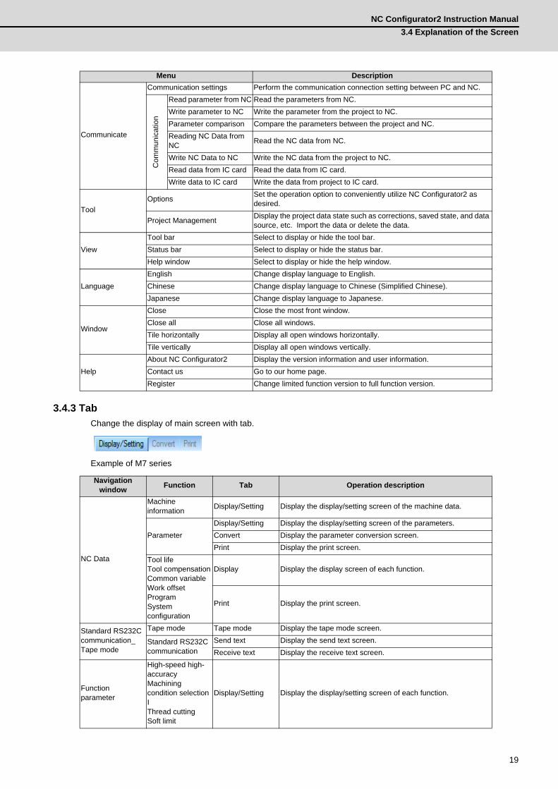
3.4.3 TabChange the display of main screen with tab.
Example of M7 series
Communicate
Communication settings Perform the communication connection setting between PC and NC.
Com
mun
icat
ion
Read parameter from NC Read the parameters from NC.Write parameter to NC Write the parameter from the project to NC.Parameter comparison Compare the parameters between the project and NC.Reading NC Data from NC Read the NC data from NC.
Write NC Data to NC Write the NC data from the project to NC.Read data from IC card Read the data from IC card.Write data to IC card Write the data from project to IC card.
ToolOptions Set the operation option to conveniently utilize NC Configurator2 as
desired.
Project Management Display the project data state such as corrections, saved state, and data source, etc. Import the data or delete the data.
ViewTool bar Select to display or hide the tool bar.Status bar Select to display or hide the status bar.Help window Select to display or hide the help window.
LanguageEnglish Change display language to English.Chinese Change display language to Chinese (Simplified Chinese).Japanese Change display language to Japanese.
Window
Close Close the most front window.Close all Close all windows.Tile horizontally Display all open windows horizontally.Tile vertically Display all open windows vertically.
HelpAbout NC Configurator2 Display the version information and user information.Contact us Go to our home page.Register Change limited function version to full function version.
Navigation window Function Tab Operation description
NC Data
Machine information Display/Setting Display the display/setting screen of the machine data.
ParameterDisplay/Setting Display the display/setting screen of the parameters.Convert Display the parameter conversion screen.Print Display the print screen.
Tool lifeTool compensationCommon variableWork offsetProgramSystem configuration
Display
Display the display screen of each function.
Print Display the print screen.
Standard RS232C communication_Tape mode
Tape mode Tape mode Display the tape mode screen.
Standard RS232C communication
Send text Display the send text screen.Receive text Display the receive text screen.
Function parameter
High-speed high-accuracyMachining condition selection IThread cuttingSoft limit
Display/Setting Display the display/setting screen of each function.
Menu Description

3 Operation ProcedureMITSUBISHI CNC
20

21
4Basic Operation
4 Basic OperationMITSUBISHI CNC
22
4.1 File FunctionUp to eight projects can be displayed on the screen at a time.
4.1.1 Create a New Project
Create a new project.4.1.1.1 Create a New Project (with Initial Setting)
M7 E70 C70 M60/M60SWith initial
setting ○ ○ ○ -
Without initial setting ○ ○ ○ ○
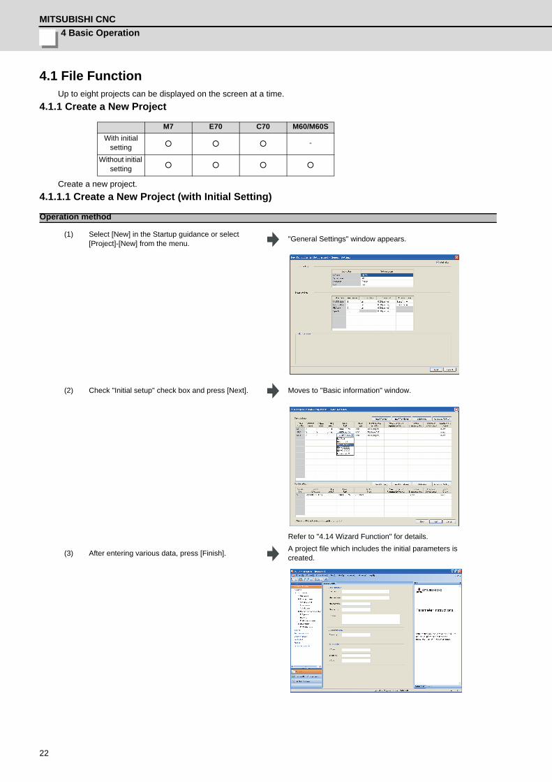
Operation method
(1) Select [New] in the Startup guidance or select [Project]-[New] from the menu. "General Settings" window appears.
(2) Check "Initial setup" check box and press [Next]. Moves to "Basic information" window.
Refer to "4.14 Wizard Function" for details.
(3) After entering various data, press [Finish]. A project file which includes the initial parameters is created.

NC Configurator2 Instruction Manual4.1 File Function
23
4.1.1.2 Create a New Project (without Initial Setting)
Operation method
(1) Select [New] in the Startup guidance or select [Project]-[New] from the menu. "New" window appears.
(2) Remove check from thecheck box of "Initial setup" at the upper right side of the screen, and click "Finish".
A project file will be created.

4 Basic OperationMITSUBISHI CNC
24
4.1.2 Open an Existing File
Open an existing project file or parameter file. It is complied with NC Configurator2's project file (*.nc2) and NC Configurator's project file (*.ncp) formats.
(1) Series name selection window appears for a project file (*.ncp) of NC Configurator. The ncp file can be opened only when specifying the same NC series type as the one which is used for the ncp file; however, when opening the project created with M70A/M70B, the ncp file can be opened with M700/M700V only.
(2) On C70, formats of common variables are different between NC Configurator and NC Configurator2. For that reason, projects that are saved by NC Comfigurator cannot be opened by NC Configurator2. In that case, move the common variable file [COMMON.VAR] to any place except for the project folder and open the project file again.
(3) It cannot open a project file named the same as that is already opened.
M7 E70 C70 M60/M60S○ ○ ○ ○
Operation Method
(1) Select [Open] in the Startup guidance or select [Project]-[Open] from the menu.
"Open" window appears.
(2) Select an existing file or parameter file and press [Open].
The project data will be read.
Caution
NC Configurator2 Instruction Manual4.1 File Function
25
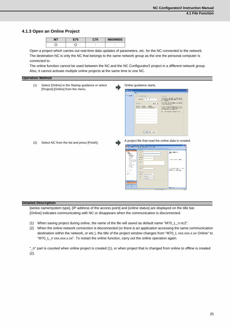
4.1.3 Open an Online Project
Open a project which carries out real-time data updates of parameters, etc. for the NC connected to the network.The destination NC is only the NC that belongs to the same network group as the one the personal computer is connected to.The online function cannot be used between the NC and the NC Configurator2 project in a different network group.Also, it cannot activate multiple online projects at the same time to one NC.
[series name/system type], [IP address of the access point] and [online status] are displayed on the title bar.[Online] indicates communicating with NC or disappears when the communication is disconnected.
(1) When saving project during online, the name of the file will saved as default name "M70_L_n.nc2".(2) When the online network connection is disconnected (or there is an application accessing the same communication
destination within the network, or etc.), the title of the project window changes from "M70_L xxx.xxx.x.xx Online" to "M70_L_n xxx.xxx.x.xx". To restart the online function, carry out the online operation again.
"_n" part is counted when online project is created (1), or when project that is changed from online to offline is created (2).
M7 E70 C70 M60/M60S○ ○ - -
Operation Method
(1) Select [Online] in the Startup guidance or select [Project]-[Online] from the menu.
Online guidance starts.
(2) Select NC from the list and press [Finish]. A project file that read the online data is created.
Detailed Description
XXX.XXX.X.X XXXXXXXXXXX XXX-XXXXXXXXXX
XXXXXXXXXX XXX XXXXXX
XXXXXXXXXXX
XXX-XXXXXXXX-XX
4 Basic OperationMITSUBISHI CNC
26
(1) The following functions cannot be used online.- Import- Parameter conversion- Read From NC and Write to NC- Tool life, Tool Compensation, Common variable, Work offset, Print program. (Parameter and system configuration can be printed.)- Project management- Function parameter
Caution
NC Configurator2 Instruction Manual4.1 File Function
27
4.1.4 Saving a Project
Select [Project]-[Save] or [Save as] from the menu to save a project.If opening multiple projects, the project data displayed in the most foreground is saved.
It cannot be saved with NC Configurator project file (*.ncp) format.
M7 E70 C70 M60/M60S○ ○ ○ ○
Caution

4 Basic OperationMITSUBISHI CNC
28
4.1.5 Importing NC Data
* Partially possible. See the following data list for details.Import the data file that is output from the NC side and create a project.
List of data that can be imported
M7 E70 C70 M60/M60S
○ ○ ○ * ○ *
Type Format M7 E70 C70 M60/M60SParameter *.PRM ○ ○ ○ ○
Tool life *.TLF ○ ○ - -Tool compensation *.OFS ○ ○ ○ -Common variable *.VAR ○ ○ ○ -Work offset *.OFS ○ ○ ○ -Program *.PRG, *.TXT ○ ○ ○ -System configuration *.INF ○ ○ - -
Operation Method
(1) Select [Import] in the Startup guidance or select [Project]-[Import] from the menu.
"Open" window appears.
(2) Select a file and press [Open]. "New" window appears.
(3) Select the NC series and press [OK]. A project file with imported data is created.
NC Configurator2 Instruction Manual4.1 File Function
29
(1) The parameters of the active project are overwritten. The NC data which related to the parameters may be changed by the imported parameters.
(2) If the series type or system type is different, the parameter data cannot be imported. An import failure message will appear, and the project will not be changed.
(3) When importing the NC data related to the parameters such as the tool life and tool compensation, the data can be imported only when the data to be imported and the parameter settings of the current project match each other.
(4) If importing a machining program, a machining program is added instead of updating the existing program in the project. (If the same file name exists, confirmation of overwriting is prompted.)
(5) This function cannot be used online.
(1) If the parameter of the data of the specified series or system type and the data to be imported do not match each other, error message will show up and the data will not be imported.
(2) If opening the NC data file created with NC Configurator M70A/M70B, it can be opened by M7/E70 series.
Caution (with an active project)
Caution (without an active project)
4 Basic OperationMITSUBISHI CNC
30
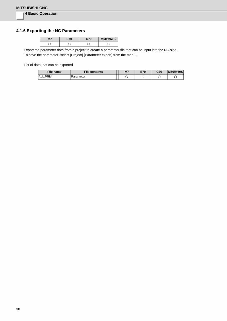
4.1.6 Exporting the NC Parameters
Export the parameter data from a project to create a parameter file that can be input into the NC side.To save the parameter, select [Project]-[Parameter export] from the menu.
List of data that can be exported
M7 E70 C70 M60/M60S○ ○ ○ ○
File name File contents M7 E70 C70 M60/M60SALL.PRM Parameter ○ ○ ○ ○

NC Configurator2 Instruction Manual4.1 File Function
31
4.1.7 Output NC Parameter (csv file format)
Output NC parameter with csv file format.
M7 E70 C70 M60/M60S○ ○ ○ -
Operation Method
(1) Select [Project]-[Output NC param as csv file] from the menu.
"Save as" window appears.
(2) Specify the file name, and press [Save]. The file will be created to the specified output destination.
Example when a file is named as "para"A separate file is created for each type of parameter for csv format.

4 Basic OperationMITSUBISHI CNC
32
4.1.8 Print
Print one of the data from parameter type, tool life, tool compensation, common variable, work offset, program, system configuration, Machining Condition Selection I and high speed high accuracy. More than one type of data cannot be printed at a time.
(1) Characters exceeding the maximum number of display characters on a printing paper may not be printed.
M7 E70 C70 M60/M60S○ ○ ○ -
Operation Method
(1) Select [Project]-[Print] from the menu or [Parameter print] tab.
Print screen will be displayed.
(2) Select the item to print and press [Print]. Data will be printed with the specified condition.
Caution
XXXXXXXXXX XXX XXXXXX
XXX-XXXXXXXX-XX
XXXXXXXXXXX

NC Configurator2 Instruction Manual4.2 Machine Information Management
33
4.2 Machine Information Management
Machine information screen appears by selecting Machine information in the navigation tree. The NC machine information for the target project can be managed.
M7 E70 C70 M60/M60S○ ○ ○ ○
4 Basic OperationMITSUBISHI CNC
34
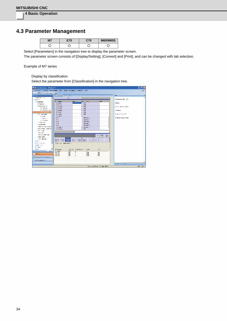
4.3 Parameter Management
Select [Parameters] in the navigation tree to display the parameter screen. The parameter screen consists of [Display/Setting], [Convert] and [Print], and can be changed with tab selection.
Example of M7 series
Display by classificationSelect the parameter from [Classification] in the navigation tree.
M7 E70 C70 M60/M60S○ ○ ○ ○
NC Configurator2 Instruction Manual4.3 Parameter Management
35
4.3.1 M7/E70 Series Parameters
(1) Number of part systemsSet it in the parameter "#1001 SYS_ON". (Up to 2 part systems + PLC system for M70/M70V/E70 series)
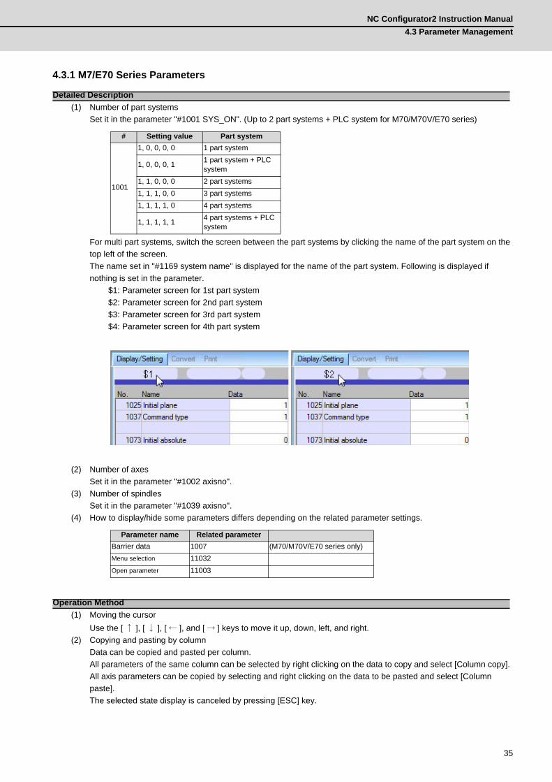
For multi part systems, switch the screen between the part systems by clicking the name of the part system on the top left of the screen. The name set in "#1169 system name" is displayed for the name of the part system. Following is displayed if nothing is set in the parameter.
$1: Parameter screen for 1st part system$2: Parameter screen for 2nd part system$3: Parameter screen for 3rd part system$4: Parameter screen for 4th part system
(2) Number of axesSet it in the parameter "#1002 axisno".
(3) Number of spindlesSet it in the parameter "#1039 axisno".
(4) How to display/hide some parameters differs depending on the related parameter settings.
(1) Moving the cursorUse the [ ↑ ], [ ↓ ], [ ← ], and [ → ] keys to move it up, down, left, and right.
(2) Copying and pasting by columnData can be copied and pasted per column.All parameters of the same column can be selected by right clicking on the data to copy and select [Column copy]. All axis parameters can be copied by selecting and right clicking on the data to be pasted and select [Column paste]. The selected state display is canceled by pressing [ESC] key.
Detailed Description
# Setting value Part system
1001
1, 0, 0, 0, 0 1 part system
1, 0, 0, 0, 1 1 part system + PLC system
1, 1, 0, 0, 0 2 part systems1, 1, 1, 0, 0 3 part systems1, 1, 1, 1, 0 4 part systems
1, 1, 1, 1, 1 4 part systems + PLC system
Parameter name Related parameterBarrier data 1007 (M70/M70V/E70 series only)Menu selection 11032Open parameter 11003
Operation Method

4 Basic OperationMITSUBISHI CNC
36
(3) Copying and pasting by areaA part of data displayed on screen can be area copied and pasted.Specify the range of data to copy, right-click and select [Area copy].Select any of the copy destination data, right-click and select [Area paste], and then the data will be copied to the same parameter.Up to 15 parameter data can be copied at a time.It can also be copied by the [Area copy] and [Area paste] buttons at the bottom of the screen.
(4) Multiple data batch inputEnter the data of multiple part systems or axes of the same parameter No. with each data delimited by slash ("/") to perform batch input.Example) To set the 1st part system of "#1003 iunit" to "B" and the 2nd part system to "C", move the cursor to #1003 and then enter "B/C".
(1) The setting range of the input data is not checked. To avoid setting the illegal value, check the setting range in "Detailed help" carefully when setting the data.
(2) Settings related to the formatting of the tool compensation and tool life with the value of the parameter "#1041 I_inch" are not supported.The judgment of whether the parameters "#8026" and "#8027" can be set with the value of the parameter "#8019 Accuracy coefficient" is not supported.
(3) The parameters #18151 to #18900 displayed on the screen are dependent on the setting of the parameter #1326, but the range check and parity check for #1326 are unavailable.
Caution

NC Configurator2 Instruction Manual4.3 Parameter Management
37
4.3.2 C70 Series Parameters
(1) Number of part systemsSet it in the parameter "#1001 SYS_ON".
For multi part systems, switch the screen between the part systems by clicking the name of the part system on the bottom left of the screen.
1: Parameter screen for 1st part system2: Parameter screen for 2nd part system :7: Parameter screen for 7th part system
(2) Number of axesSet it in the parameter "#1002 axisno".
(3) Number of spindlesSet it in the parameter "#1039 axisno".
(1) Moving the cursorUse the [ ↑ ], [ ↓ ], [ ← ], and [ → ] keys to move it up, down, left, and right.
(2) Column copy and pastingData can be copied and pasted per column.All axis parameters can be selected by right clicking on the data to copy and select [Column copy]. All axis parameters can be copied by selecting and right clicking on the data to be pasted and select [Column paste]. The selected state display is canceled by pressing [ESC] key.
(3) Area copy and pasteA part of data displayed on screen can be area copy and paste.Right click the data to copy and select [Area copy].Data can be copied by select and right click on the data to be pasted and select [Area paste], and data will be copied to same parameter.Up to 15 parameter data can be copied at same time.It can be copied by button [Area copy] and [Area paste] at bottom of the screen.
Detailed Description
# Setting value Part system
1001
1, 0, 0, 0, 0, 0, 0, 0 1 part system
1, 0, 0, 0, 0, 0, 0, 1 1 part system + PLC system
1, 1, 0, 0, 0, 0, 0, 0 2 part systems1, 1, 1, 0, 0, 0, 0, 0 3 part systems: :
1, 1, 1, 1, 1, 1, 1, 1 7 part systems + PLC system
Operation Method
4 Basic OperationMITSUBISHI CNC
38
(1) The setting range of the input data is not checked. To avoid setting the illegal value, check the setting range in "Detailed help" carefully when setting the data.
(2) Settings related to the formatting of the tool compensation and tool life with the value of the parameter "#1041 I_inch" are not supported.The judgment of whether the parameters "#8026" and "#8027" can be set with the value of the parameter "#8019 Accuracy coefficient" is not supported.
Caution
NC Configurator2 Instruction Manual4.3 Parameter Management
39
4.3.3 M60/M60S Series Parameters
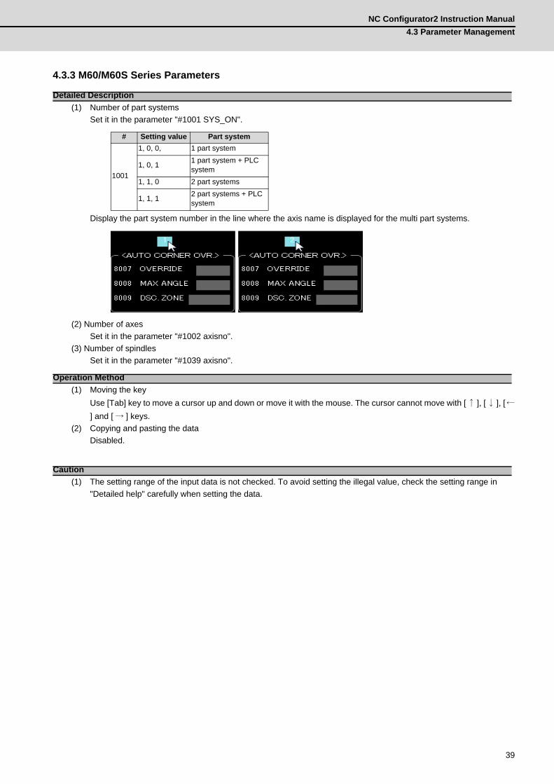
(1) Number of part systemsSet it in the parameter "#1001 SYS_ON".
Display the part system number in the line where the axis name is displayed for the multi part systems.
(2) Number of axesSet it in the parameter "#1002 axisno".
(3) Number of spindlesSet it in the parameter "#1039 axisno".
(1) Moving the keyUse [Tab] key to move a cursor up and down or move it with the mouse. The cursor cannot move with [↑ ], [↓ ], [←] and [ → ] keys.
(2) Copying and pasting the dataDisabled.
(1) The setting range of the input data is not checked. To avoid setting the illegal value, check the setting range in "Detailed help" carefully when setting the data.
Detailed Description
# Setting value Part system
1001
1, 0, 0, 1 part system
1, 0, 1 1 part system + PLC system
1, 1, 0 2 part systems
1, 1, 1 2 part systems + PLC system
Operation Method
Caution

4 Basic OperationMITSUBISHI CNC
40
4.3.4 Parameter Search
The related parameter can be searched from the keyword. Select [Search] tab in the Help window. To display the list of related parameter, enter the keyword and press [Search]. Double click on the parameter in the list to move the cursor to the appropriate parameter.
4.3.5 Parameter Modification History
Modified parameters are displayed in modification time order. The oldest one is displayed on the bottom and the latest one is displayed on the top. Click on the parameter in the history to switch to the display screen of the appropriate parameter. Double click on the history data to display the window to select whether to undo the modified data. Select [Yes] to undo the parameter setting value, and simultaneously record a new modification history.
(1) If changing the parameters online, the function to undo the parameter setting value by double clicking the history is invalid.
(2) If reading the parameters from the NC or importing parameters from an external parameter file, the parameter history is cleared.
(3) If undoing the setting value by double clicking the parameter history, the linked parameters are simultaneously changed.
M7 E70 C70 M60/M60SSearch ○ ○ ○ ○
Move ○ ○ ○ -
M7 E70 C70 M60/M60SHistory ○ ○ ○ ○
Move ○ ○ ○ ○
Return ○ ○ ○ -
Caution
NC Configurator2 Instruction Manual4.3 Parameter Management
41
4.3.6 Parameter Conversion
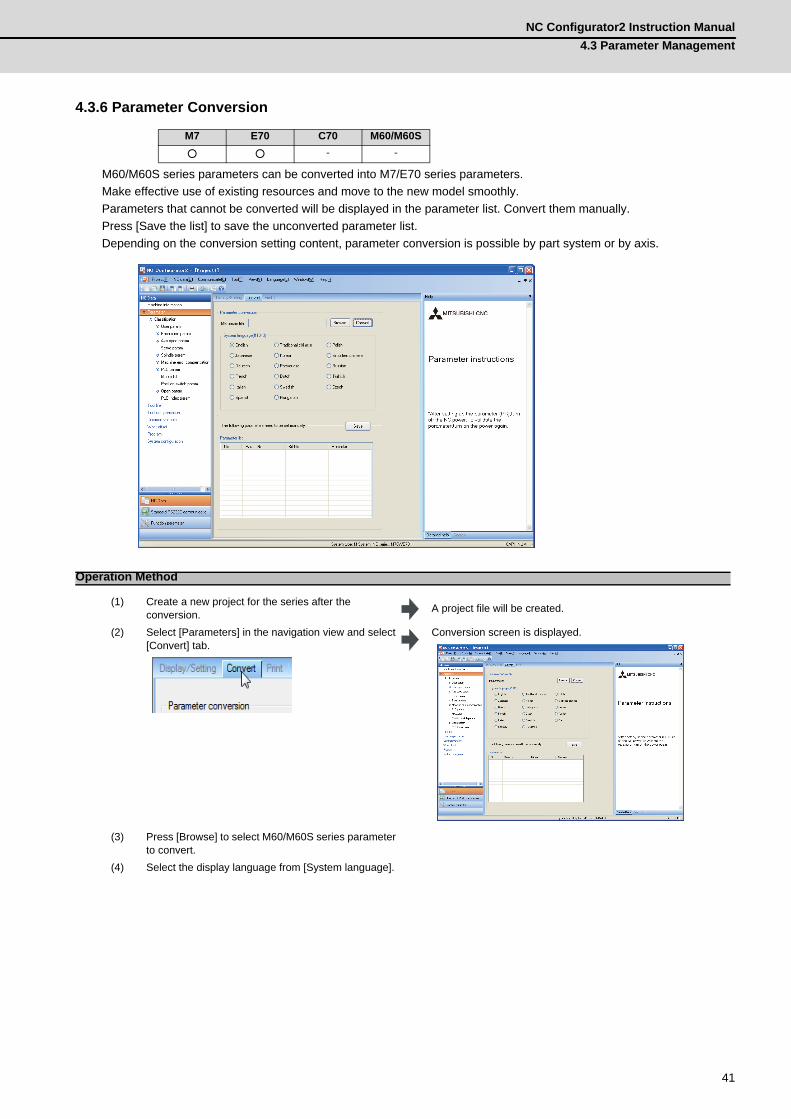
M60/M60S series parameters can be converted into M7/E70 series parameters. Make effective use of existing resources and move to the new model smoothly. Parameters that cannot be converted will be displayed in the parameter list. Convert them manually. Press [Save the list] to save the unconverted parameter list. Depending on the conversion setting content, parameter conversion is possible by part system or by axis.
M7 E70 C70 M60/M60S○ ○ - -
Operation Method
(1) Create a new project for the series after the conversion. A project file will be created.
(2) Select [Parameters] in the navigation view and select [Convert] tab.
Conversion screen is displayed.
(3) Press [Browse] to select M60/M60S series parameter
to convert.(4) Select the display language from [System language].
4 Basic OperationMITSUBISHI CNC
42
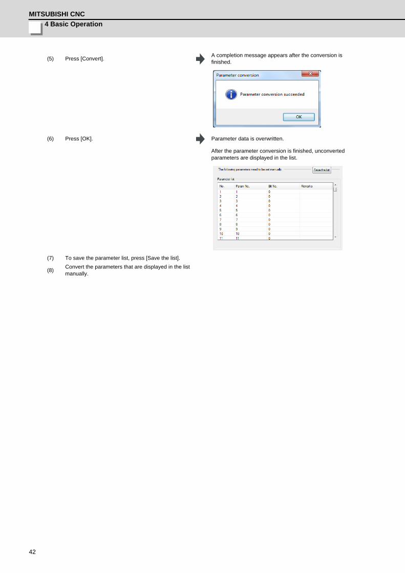
(5) Press [Convert]. A completion message appears after the conversion is finished.
(6) Press [OK]. Parameter data is overwritten.
After the parameter conversion is finished, unconverted parameters are displayed in the list.
(7) To save the parameter list, press [Save the list].
(8) Convert the parameters that are displayed in the list manually.

NC Configurator2 Instruction Manual4.3 Parameter Management
43
4.3.7 Parameter Comparison
Compare the parameters between two projects.
The parameters of the active project and the destination NC are compared for M60/M60S series. Compare the parameters by selecting [Communicate]-[Communication]-[Parameter comparison] from the menu.
M7 E70 C70 M60/M60S○ ○ ○ ○
Operation method (M7/E70 series, C70 series)
(1) Open the two project files to be compared.
(2) Select [Tool]-[Param comparison] from the menu. Selection screen for the project files to be compared appears.
(3) Select the projects to compare and press [Compare]. Comparison result will be displayed.
Operation method (M60 series/M60S series)
4 Basic OperationMITSUBISHI CNC
44
4.4 Tool Life Data Management
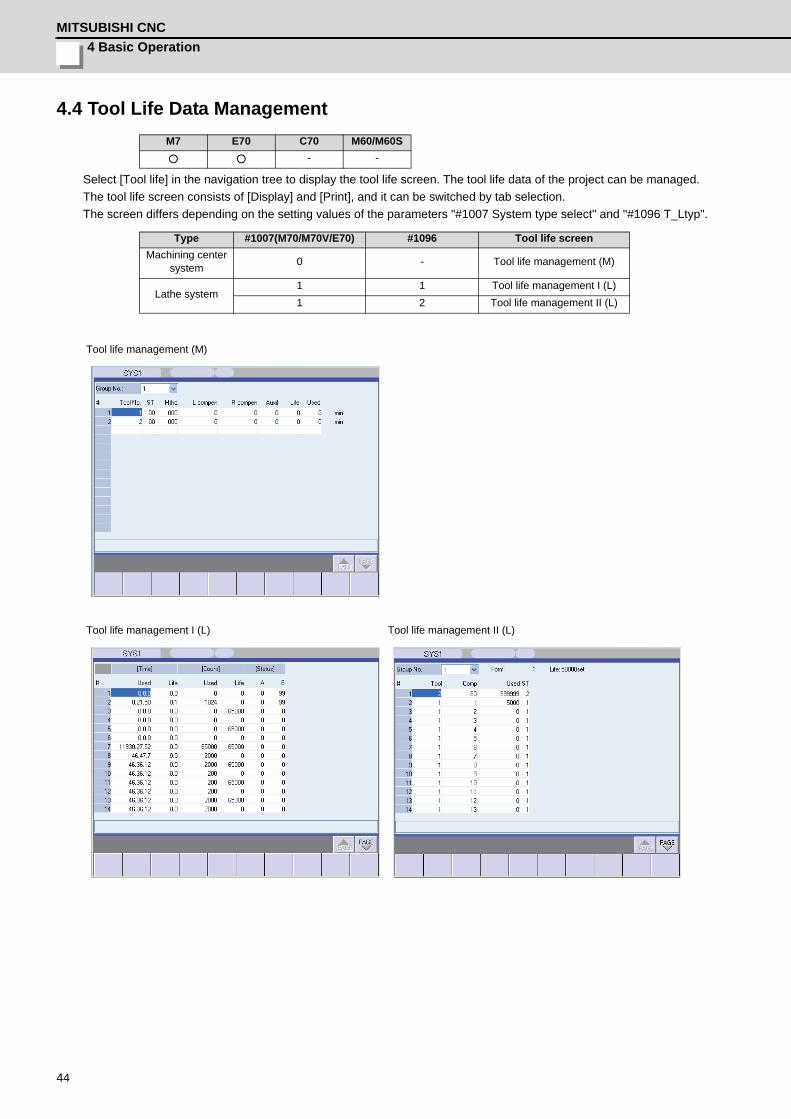
Select [Tool life] in the navigation tree to display the tool life screen. The tool life data of the project can be managed. The tool life screen consists of [Display] and [Print], and it can be switched by tab selection. The screen differs depending on the setting values of the parameters "#1007 System type select" and "#1096 T_Ltyp".
M7 E70 C70 M60/M60S○ ○ - -
Type #1007(M70/M70V/E70) #1096 Tool life screenMachining center
system 0 - Tool life management (M)
Lathe system1 1 Tool life management I (L)1 2 Tool life management II (L)
Tool life management (M)
Tool life management I (L) Tool life management II (L)

NC Configurator2 Instruction Manual4.5 Tool Compensation Data Management
45
4.5 Tool Compensation Data Management
Select Tool compensation in the navigation tree to display the tool compensation screen. The tool compensation data of the project can be managed. The tool compensation screen consists of [Display] and [Print] and it can be switched by tab selection. The screen differs depending on the setting value of the parameter "#1037 cmdtyp".
(1) For Lathe system, wear data and tool length data can be set for up to three axes. Even when the number of the set axes exceeds three, only three axes are displayed.
(2) If an axis name on the NC side is not read when reading the tool compensation in a project of the lathe system, the reading cannot be done. Read the parameters first, or read the tool compensation and the parameters at the same time.
M7 E70 C70 M60/M60S○ ○ ○ -
Type #1007(M70/M70V/E70) #1037 Tool compensation screen
Machining center system
0 1 Tool compensation List 1 (for M) Type A0 2 Tool compensation List 1 (for M) Type B
Lathe system 1 3 Tool compensation List 2 (for L) Type C
Tool compensation List 1 (for M) Type A Tool compensation List 1 (for M) Type B
Tool compensation List 2 (for L) Type C
Caution
4 Basic OperationMITSUBISHI CNC
46
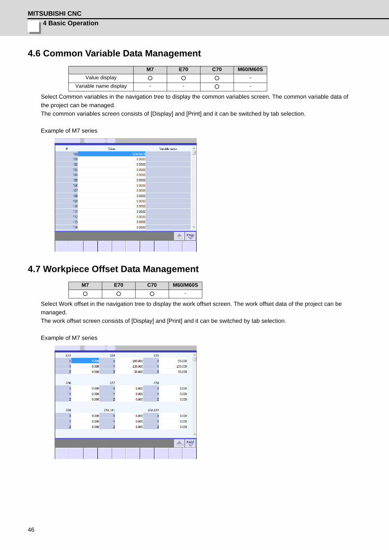
4.6 Common Variable Data Management
Select Common variables in the navigation tree to display the common variables screen. The common variable data of the project can be managed. The common variables screen consists of [Display] and [Print] and it can be switched by tab selection.
Example of M7 series
4.7 Workpiece Offset Data Management
Select Work offset in the navigation tree to display the work offset screen. The work offset data of the project can be managed. The work offset screen consists of [Display] and [Print] and it can be switched by tab selection.
Example of M7 series
M7 E70 C70 M60/M60SValue display ○ ○ ○ -
Variable name display - - ○ -
M7 E70 C70 M60/M60S○ ○ ○ -
NC Configurator2 Instruction Manual4.8 Machining Program Management
47
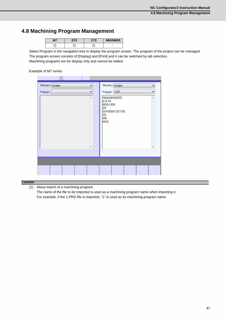
4.8 Machining Program Management
Select Program in the navigation tree to display the program screen. The program of the project can be managed. The program screen consists of [Display] and [Print] and it can be switched by tab selection.Machining programs are for display only and cannot be edited.
Example of M7 series
(1) About import of a machining programThe name of the file to be imported is used as a machining program name when importing it.For example, if the 1.PRG file is imported, "1" is used as its machining program name.
M7 E70 C70 M60/M60S○ ○ ○ -
Caution
4 Basic OperationMITSUBISHI CNC
48
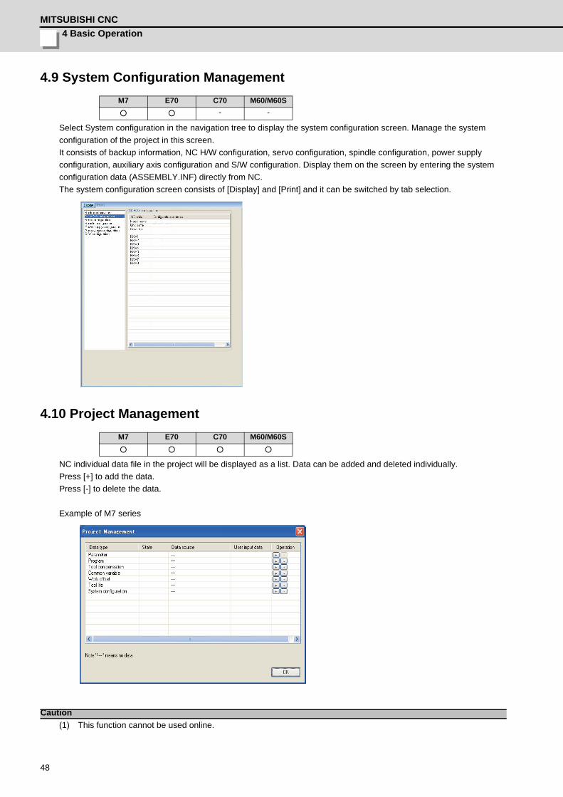
4.9 System Configuration Management
Select System configuration in the navigation tree to display the system configuration screen. Manage the system configuration of the project in this screen.It consists of backup information, NC H/W configuration, servo configuration, spindle configuration, power supply configuration, auxiliary axis configuration and S/W configuration. Display them on the screen by entering the system configuration data (ASSEMBLY.INF) directly from NC. The system configuration screen consists of [Display] and [Print] and it can be switched by tab selection.
4.10 Project Management
NC individual data file in the project will be displayed as a list. Data can be added and deleted individually. Press [+] to add the data. Press [-] to delete the data.
Example of M7 series
(1) This function cannot be used online.
M7 E70 C70 M60/M60S○ ○ - -
M7 E70 C70 M60/M60S○ ○ ○ ○
Caution
NC Configurator2 Instruction Manual4.11 Read and Write the NC Data
49
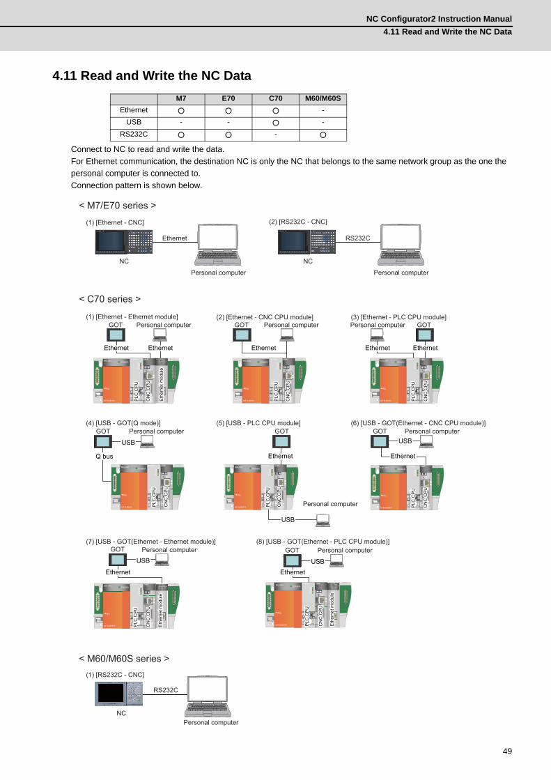
4.11 Read and Write the NC Data
Connect to NC to read and write the data.For Ethernet communication, the destination NC is only the NC that belongs to the same network group as the one the personal computer is connected to.Connection pattern is shown below.
M7 E70 C70 M60/M60SEthernet ○ ○ ○ -
USB - - ○ -RS232C ○ ○ - ○
NC
Personal computer
Ethernet RS232C
(1) [Ethernet - CNC] (2) [RS232C - CNC]
USBUSBUSB
(1) [Ethernet - Ethernet module] (2) [Ethernet - CNC CPU module]
(4) [USB - GOT(Q mode)] (5) [USB - PLC CPU module] (6) [USB - GOT(Ethernet - CNC CPU module)]
(7) [USB - GOT(Ethernet - Ethernet module)] (8) [USB - GOT(Ethernet - PLC CPU module)]
(3) [Ethernet - PLC CPU module]
(1) [RS232C - CNC]
< M7/E70 series >
< C70 series >
< M60/M60S series >
USBUSBUSB
GOT
USBUSBUSB
GOT
USBUSBUSBGOT
NC
Personal computer
RS232C
NC
EthernetEthernetEthernet
EthernetEthernetEthernet EthernetEthernetEthernet
EthernetEthernetEthernet
GOT
GOT Personal computer
EthernetEthernetEthernet EthernetEthernetEthernet EthernetEthernetEthernet
GOT Personal computer
CN
C C
PU
CN
C C
PU
CN
C C
PU
USBUSBUSB
Q busQ busQ bus
GOT
CN
C C
PU
CN
C C
PU
CN
C C
PU
CN
C C
PU
CN
C C
PU
CN
C C
PU
EthernetEthernetEthernet EthernetEthernetEthernet
GOT Personal computer
CN
C C
PU
CN
C C
PU
CN
C C
PU
CN
C C
PU
CN
C C
PU
CN
C C
PU
Personal computer Personal computer
Personal computer
Personal computer
Personal computer
Personal computer
CN
C C
PU
CN
C C
PU
CN
C C
PU
PLC
CP
UP
LC C
PU
PLC
CP
U
Eth
erne
t mod
ule
Eth
erne
t mod
ule
Eth
erne
t mod
ule
PLC
CP
UP
LC C
PU
PLC
CP
U
PLC
CP
UP
LC C
PU
PLC
CP
U
PLC
CP
UP
LC C
PU
PLC
CP
U
PLC
CP
UP
LC C
PU
PLC
CP
U
PLC
CP
UP
LC C
PU
PLC
CP
U
CN
C C
PU
CN
C C
PU
CN
C C
PU
PLC
CP
UP
LC C
PU
PLC
CP
U
Eth
erne
t mod
ule
Eth
erne
t mod
ule
Eth
erne
t mod
ule
CN
C C
PU
CN
C C
PU
CN
C C
PU
PLC
CP
UP
LC C
PU
PLC
CP
U
Eth
erne
t mod
ule
Eth
erne
t mod
ule
Eth
erne
t mod
ule
4 Basic OperationMITSUBISHI CNC
50
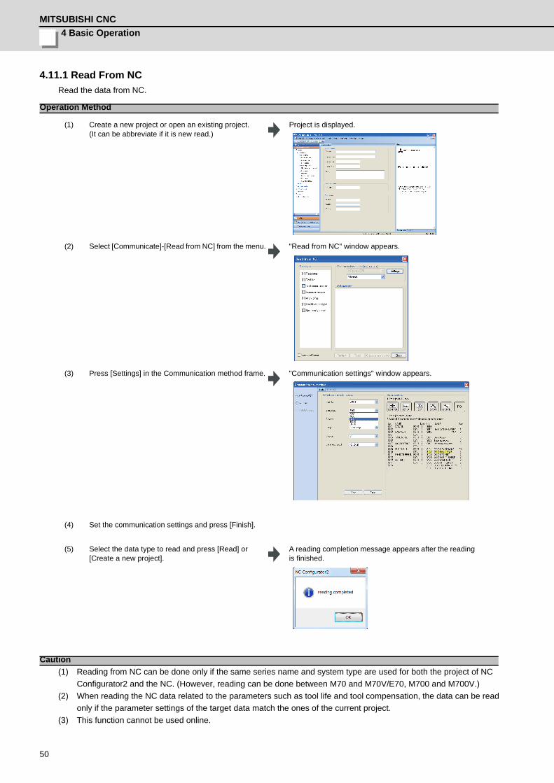
4.11.1 Read From NCRead the data from NC.
(1) Reading from NC can be done only if the same series name and system type are used for both the project of NC Configurator2 and the NC. (However, reading can be done between M70 and M70V/E70, M700 and M700V.)
(2) When reading the NC data related to the parameters such as tool life and tool compensation, the data can be read only if the parameter settings of the target data match the ones of the current project.
(3) This function cannot be used online.
Operation Method
(1) Create a new project or open an existing project.(It can be abbreviate if it is new read.)
Project is displayed.
(2) Select [Communicate]-[Read from NC] from the menu. "Read from NC" window appears.
(3) Press [Settings] in the Communication method frame. "Communication settings" window appears.
(4) Set the communication settings and press [Finish].
(5) Select the data type to read and press [Read] or [Create a new project].
A reading completion message appears after the reading is finished.
Caution

NC Configurator2 Instruction Manual4.11 Read and Write the NC Data
51
4.11.2 Write To NCWrite parameters to NC.
(1) Writing out to the NC can be done only if the same series name and system type are used for both the project of NC Configurator2 and the NC. (However, writing can be done between M70 and M70V/E70, M700 and M700V.)
(2) This function cannot be used online.
Operation Method
(1) Set the data to the project.
(2) Select [Communicate]-[Write to NC(Parameter)] from the menu.
"Write to NC(Parameter)" window appears.
(3) Press [Settings] in the Communication method frame. "Communication settings" window appears.
(4) Set the communication settings and press [Finish].
(5) Select parameter to write, and press [Write]. A writing completion message appears after the writing is finished.
Caution
4 Basic OperationMITSUBISHI CNC
52
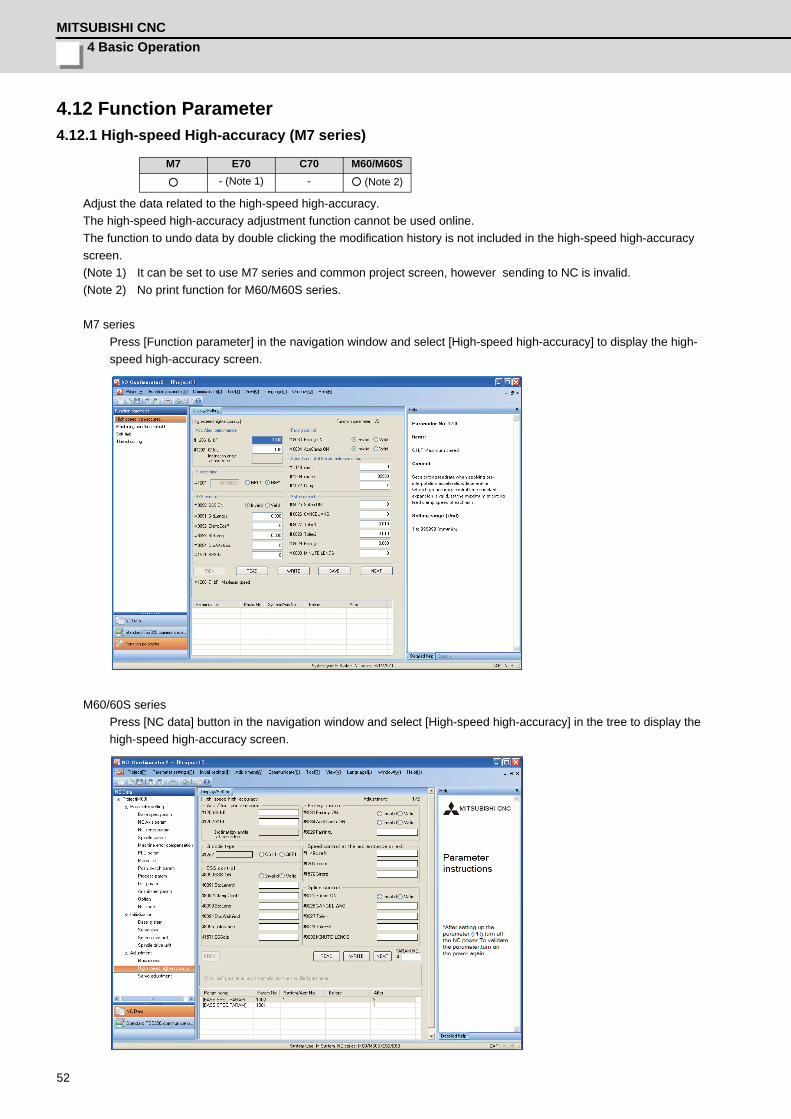
4.12 Function Parameter4.12.1 High-speed High-accuracy (M7 series)
Adjust the data related to the high-speed high-accuracy.The high-speed high-accuracy adjustment function cannot be used online.The function to undo data by double clicking the modification history is not included in the high-speed high-accuracy screen.(Note 1) It can be set to use M7 series and common project screen, however sending to NC is invalid.(Note 2) No print function for M60/M60S series.
M7 seriesPress [Function parameter] in the navigation window and select [High-speed high-accuracy] to display the high-speed high-accuracy screen.
M60/60S seriesPress [NC data] button in the navigation window and select [High-speed high-accuracy] in the tree to display the high-speed high-accuracy screen.
M7 E70 C70 M60/M60S
○ - (Note 1) - ○ (Note 2)
NC Configurator2 Instruction Manual4.12 Function Parameter
53
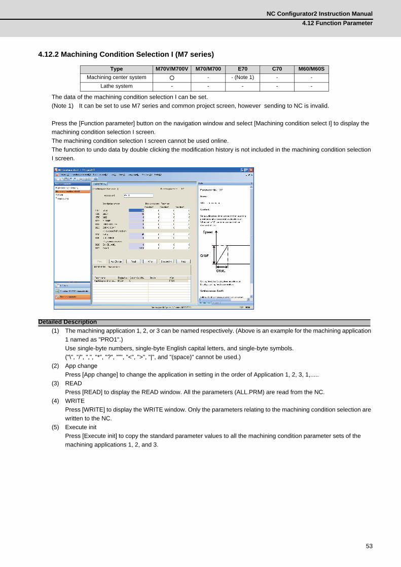
4.12.2 Machining Condition Selection I (M7 series)
The data of the machining condition selection I can be set.(Note 1) It can be set to use M7 series and common project screen, however sending to NC is invalid.
Press the [Function parameter] button on the navigation window and select [Machining condition select I] to display the machining condition selection I screen.The machining condition selection I screen cannot be used online.The function to undo data by double clicking the modification history is not included in the machining condition selection I screen.
(1) The machining application 1, 2, or 3 can be named respectively. (Above is an example for the machining application 1 named as "PRO1".)Use single-byte numbers, single-byte English capital letters, and single-byte symbols.("\", "/", ",", "*", "?", "”", "<", ">", "|", and "(space)" cannot be used.)
(2) App changePress [App change] to change the application in setting in the order of Application 1, 2, 3, 1,.....
(3) READPress [READ] to display the READ window. All the parameters (ALL.PRM) are read from the NC.
(4) WRITEPress [WRITE] to display the WRITE window. Only the parameters relating to the machining condition selection are written to the NC.
(5) Execute initPress [Execute init] to copy the standard parameter values to all the machining condition parameter sets of the machining applications 1, 2, and 3.
Type M70V/M700V M70/M700 E70 C70 M60/M60SMachining center system ○ - - (Note 1) - -
Lathe system - - - - -
Detailed Description
4 Basic OperationMITSUBISHI CNC
54
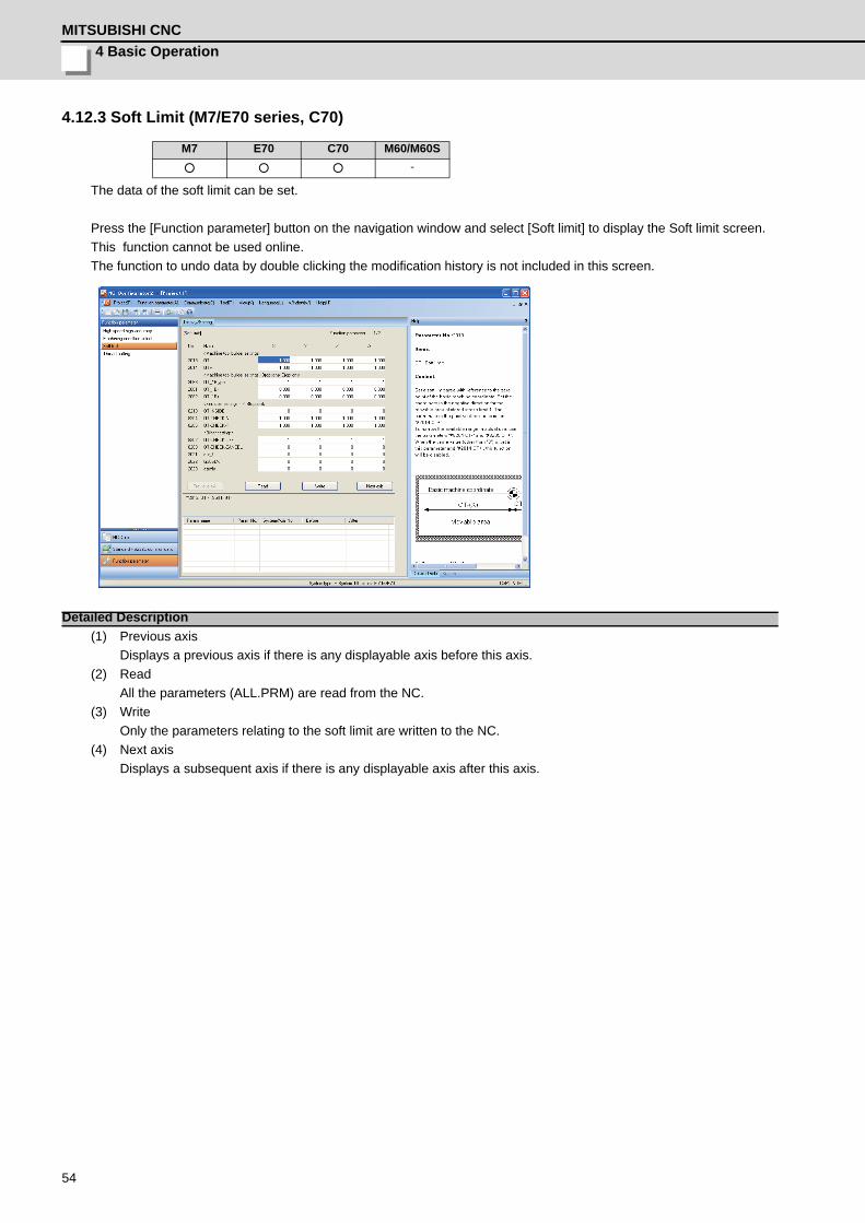
4.12.3 Soft Limit (M7/E70 series, C70)
The data of the soft limit can be set.
Press the [Function parameter] button on the navigation window and select [Soft limit] to display the Soft limit screen.This function cannot be used online. The function to undo data by double clicking the modification history is not included in this screen.
(1) Previous axisDisplays a previous axis if there is any displayable axis before this axis.
(2) ReadAll the parameters (ALL.PRM) are read from the NC.
(3) WriteOnly the parameters relating to the soft limit are written to the NC.
(4) Next axisDisplays a subsequent axis if there is any displayable axis after this axis.
M7 E70 C70 M60/M60S○ ○ ○ -
Detailed Description
NC Configurator2 Instruction Manual4.12 Function Parameter
55
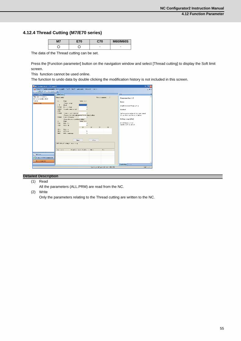
4.12.4 Thread Cutting (M7/E70 series)
The data of the Thread cutting can be set.
Press the [Function parameter] button on the navigation window and select [Thread cutting] to display the Soft limit screen.This function cannot be used online. The function to undo data by double clicking the modification history is not included in this screen.
(1) ReadAll the parameters (ALL.PRM) are read from the NC.
(2) WriteOnly the parameters relating to the Thread cutting are written to the NC.
M7 E70 C70 M60/M60S○ ○ - -
Detailed Description
4 Basic OperationMITSUBISHI CNC
56
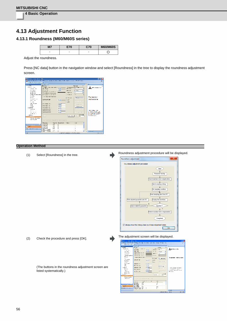
4.13 Adjustment Function4.13.1 Roundness (M60/M60S series)
Adjust the roundness.
Press [NC data] button in the navigation window and select [Roundness] in the tree to display the roundness adjustment screen.
M7 E70 C70 M60/M60S- - - ○
Operation Method
(1) Select [Roundness] in the tree. Roundness adjustment procedure will be displayed.
(2) Check the procedure and press [OK]. The adjustment screen will be displayed.
(The buttons in the roundness adjustment screen are listed systematically.)

NC Configurator2 Instruction Manual4.13 Adjustment Function
57
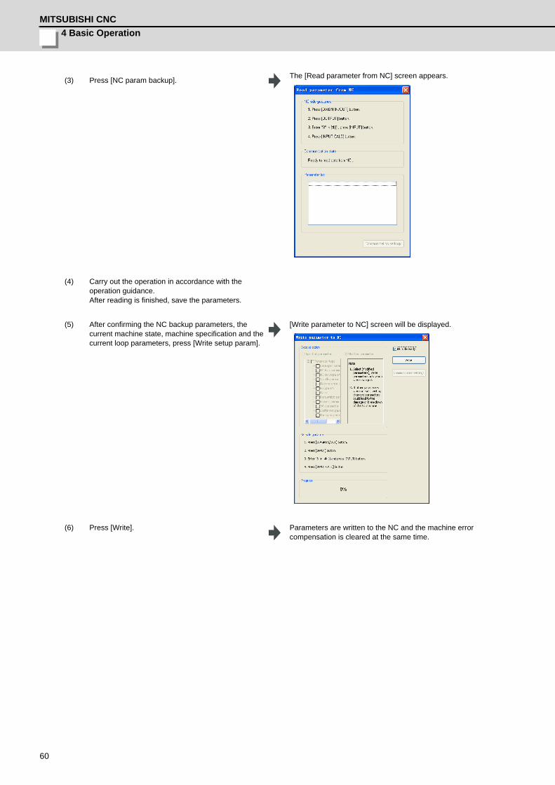
(3) Press [NC param backup]. The [Read parameter from NC] screen appears.
(4) Carry out the operation in accordance with the
operation guidance. After reading is finished, save the parameters.
(5) Press [Error comp.cancel].All the machine error compensation related parameters are cleared. [Write parameter to NC] screen will be displayed.
(6) Carry out the operation in accordance with the operation guidance. Press [Write].
A completion message appears after the writing is finished.
(7) Press [OK]. The completion message and [Write parameter to NC] screen are closed.
4 Basic OperationMITSUBISHI CNC
58
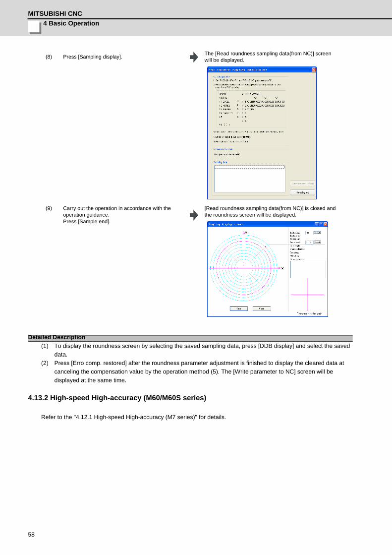
(1) To display the roundness screen by selecting the saved sampling data, press [DDB display] and select the saved data.
(2) Press [Erro comp. restored] after the roundness parameter adjustment is finished to display the cleared data at canceling the compensation value by the operation method (5). The [Write parameter to NC] screen will be displayed at the same time.
4.13.2 High-speed High-accuracy (M60/M60S series)
Refer to the "4.12.1 High-speed High-accuracy (M7 series)" for details.
(8) Press [Sampling display]. The [Read roundness sampling data(from NC)] screen will be displayed.
(9) Carry out the operation in accordance with the
operation guidance. Press [Sample end].
[Read roundness sampling data(from NC)] is closed and the roundness screen will be displayed.
Detailed Description

NC Configurator2 Instruction Manual4.13 Adjustment Function
59
4.13.3 Servo Adjustment (M60/M60S series)
Adjust the servo in this screen.
Press [NC data] in the navigation window and select [Servo adjustment] in the tree to display the servo adjustment screen.
M7 E70 C70 M60/M60S- - - ○
Operation Method
(1) Select [Servo adjustment] in the tree. Servo adjustment procedure will be displayed.
(2) Check the procedure and press [OK]. The adjustment screen will be displayed.
4 Basic OperationMITSUBISHI CNC
60
(3) Press [NC param backup]. The [Read parameter from NC] screen appears.
(4) Carry out the operation in accordance with the operation guidance. After reading is finished, save the parameters.
(5) After confirming the NC backup parameters, the current machine state, machine specification and the current loop parameters, press [Write setup param].
[Write parameter to NC] screen will be displayed.
(6) Press [Write]. Parameters are written to the NC and the machine error compensation is cleared at the same time.
NC Configurator2 Instruction Manual4.13 Adjustment Function
61
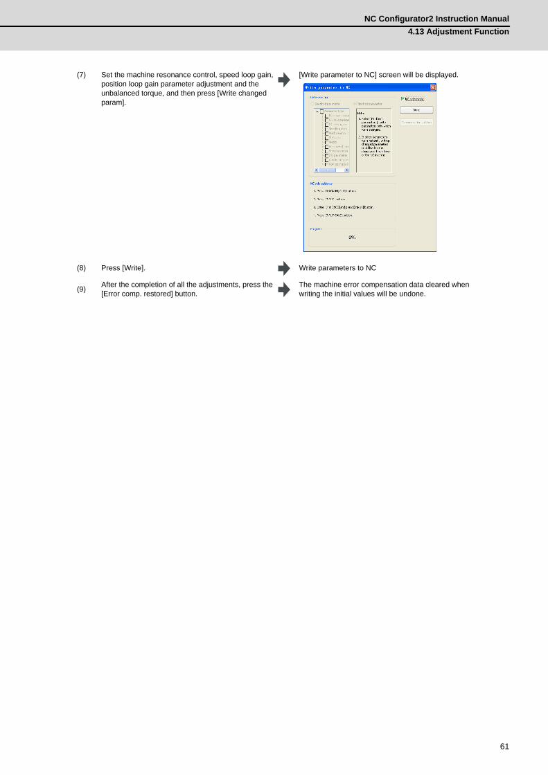
(7) Set the machine resonance control, speed loop gain, position loop gain parameter adjustment and the unbalanced torque, and then press [Write changed param].
[Write parameter to NC] screen will be displayed.
(8) Press [Write]. Write parameters to NC
(9) After the completion of all the adjustments, press the [Error comp. restored] button.
The machine error compensation data cleared when writing the initial values will be undone.
4 Basic OperationMITSUBISHI CNC
62
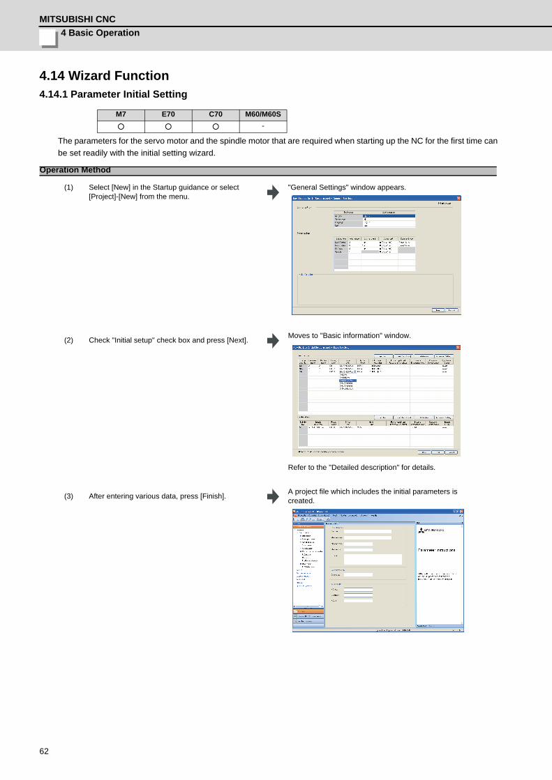
4.14 Wizard Function4.14.1 Parameter Initial Setting
The parameters for the servo motor and the spindle motor that are required when starting up the NC for the first time can be set readily with the initial setting wizard.
M7 E70 C70 M60/M60S○ ○ ○ -
Operation Method
(1) Select [New] in the Startup guidance or select [Project]-[New] from the menu.
"General Settings" window appears.
(2) Check "Initial setup" check box and press [Next]. Moves to "Basic information" window.
Refer to the "Detailed description" for details.
(3) After entering various data, press [Finish]. A project file which includes the initial parameters is created.
NC Configurator2 Instruction Manual4.14 Wizard Function
63
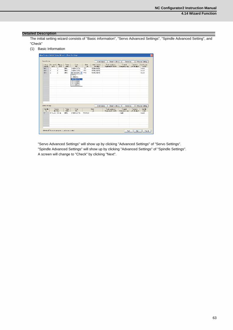
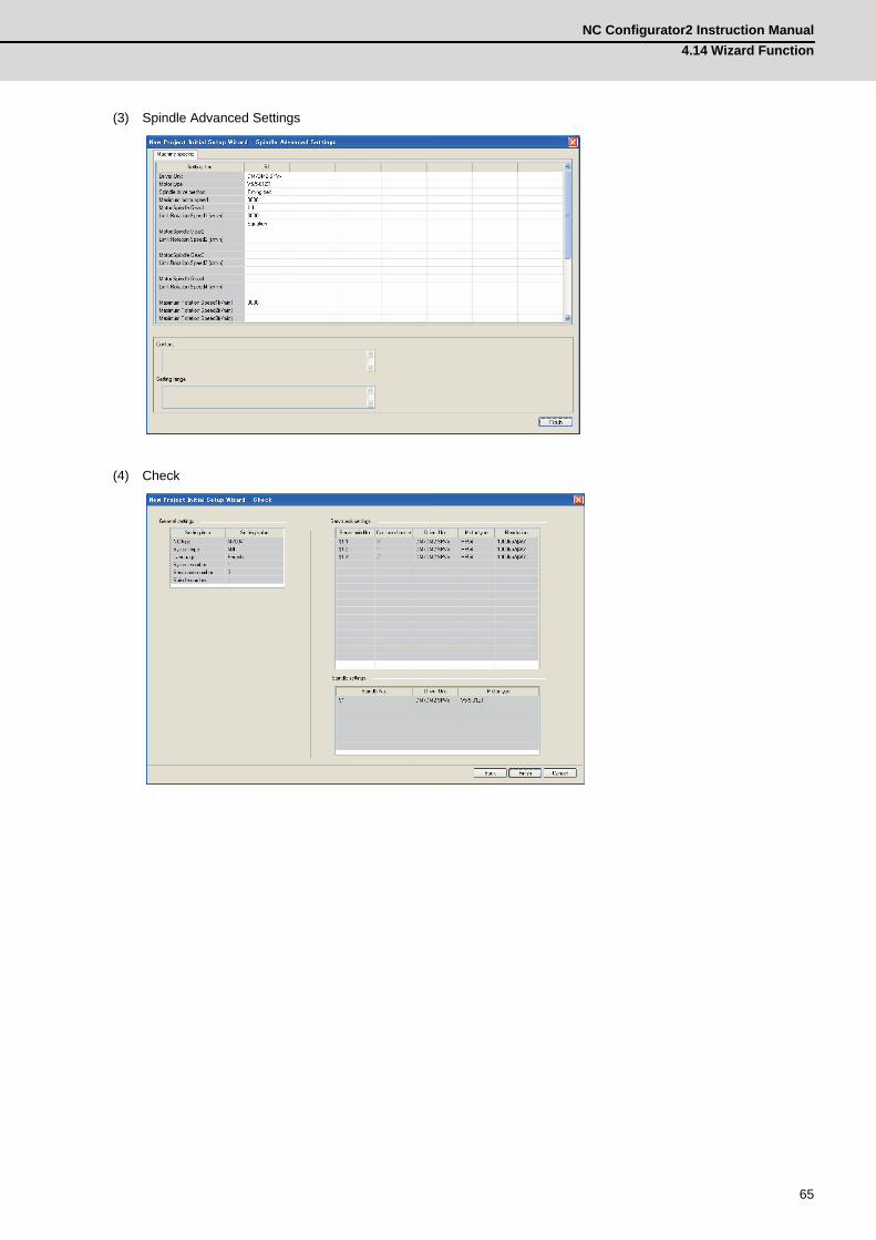
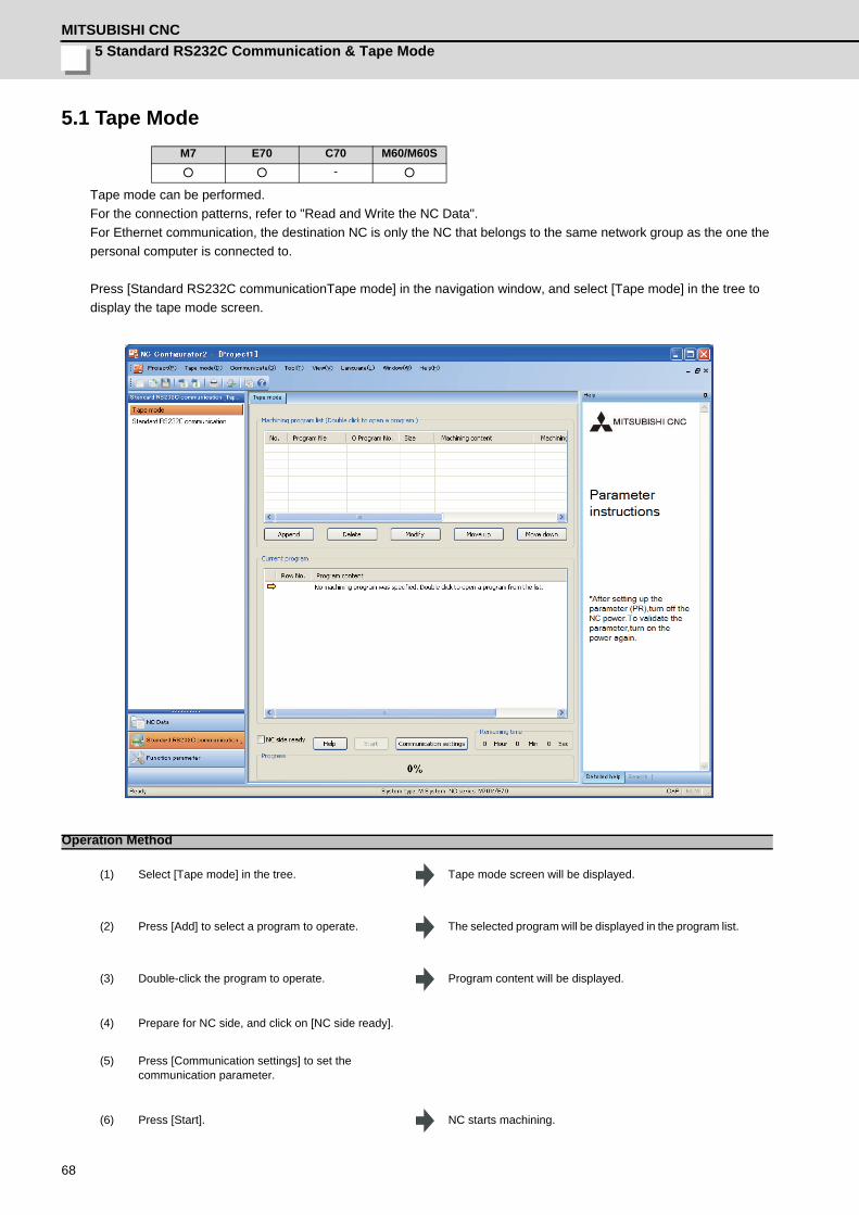
The initial setting wizard consists of "Basic information", "Servo Advanced Settings", "Spindle Advanced Setting", and "Check"(1) Basic Information
"Servo Advanced Settings" will show up by clicking "Advanced Settings" of "Servo Settings"."Spindle Advanced Settings" will show up by clicking "Advanced Settings" of "Spindle Settings".A screen will change to "Check" by clicking "Next".
Detailed Description
4 Basic OperationMITSUBISHI CNC
64
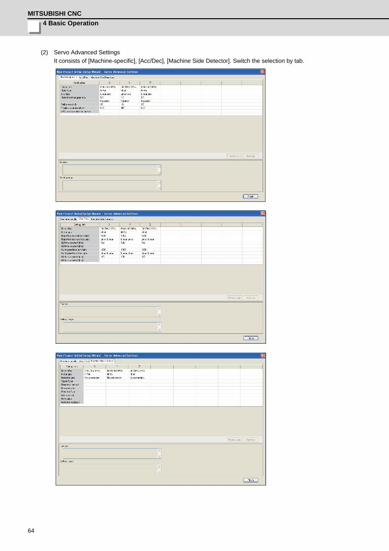
(2) Servo Advanced SettingsIt consists of [Machine-specific], [Acc/Dec], [Machine Side Detector]. Switch the selection by tab.
NC Configurator2 Instruction Manual4.14 Wizard Function
65
(3) Spindle Advanced Settings
(4) Check

4 Basic OperationMITSUBISHI CNC
66

67
5Standard RS232C Communication
& Tape Mode
5 Standard RS232C Communication & Tape ModeMITSUBISHI CNC
68
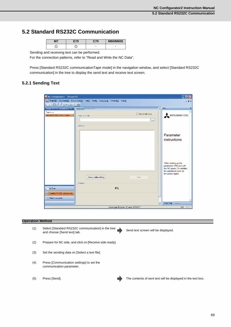
5.1 Tape Mode
Tape mode can be performed.For the connection patterns, refer to "Read and Write the NC Data". For Ethernet communication, the destination NC is only the NC that belongs to the same network group as the one the personal computer is connected to.
Press [Standard RS232C communicationTape mode] in the navigation window, and select [Tape mode] in the tree to display the tape mode screen.
M7 E70 C70 M60/M60S○ ○ - ○
Operation Method
(1) Select [Tape mode] in the tree. Tape mode screen will be displayed.
(2) Press [Add] to select a program to operate. The selected program will be displayed in the program list.
(3) Double-click the program to operate. Program content will be displayed.
(4) Prepare for NC side, and click on [NC side ready].
(5) Press [Communication settings] to set the communication parameter.
(6) Press [Start]. NC starts machining.
NC Configurator2 Instruction Manual5.2 Standard RS232C Communication
69
5.2 Standard RS232C Communication
Sending and receiving text can be performed.For the connection patterns, refer to "Read and Write the NC Data".
Press [Standard RS232C communicationTape mode] in the navigation window, and select [Standard RS232C communication] in the tree to display the send text and receive text screen.
5.2.1 Sending Text
M7 E70 C70 M60/M60S○ ○ - -
Operation Method
(1) Select [Standard RS232C communication] in the tree and choose [Send text] tab. Send text screen will be displayed.
(2) Prepare for NC side, and click on [Receive side ready].
(3) Set the sending data on [Select a text file].
(4) Press [Communication settings] to set the communication parameter.
(5) Press [Send]. The contents of sent text will be displayed in the text box.
5 Standard RS232C Communication & Tape ModeMITSUBISHI CNC
70
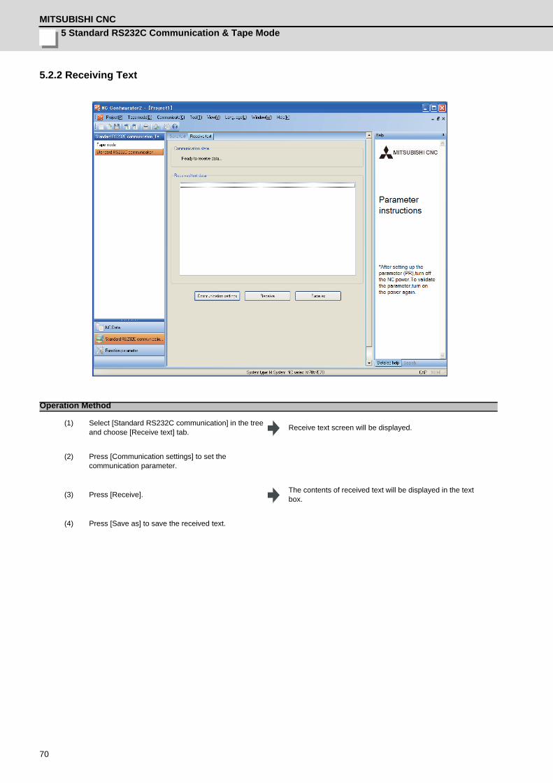
5.2.2 Receiving Text
Operation Method
(1) Select [Standard RS232C communication] in the tree and choose [Receive text] tab. Receive text screen will be displayed.
(2) Press [Communication settings] to set the communication parameter.
(3) Press [Receive]. The contents of received text will be displayed in the text box.
(4) Press [Save as] to save the received text.

71
付録 Ap1 章
71
Appendix 1Registration after installation
Appendix 1 Registration after installationMITSUBISHI CNC
72
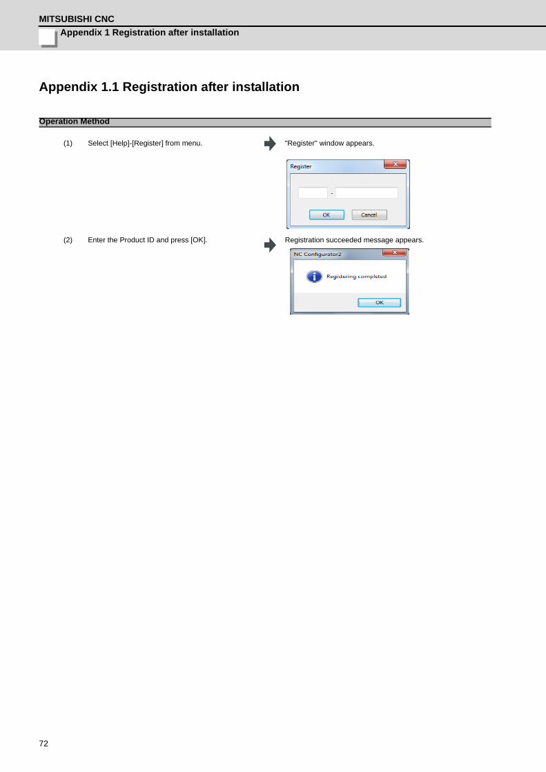
Appendix 1.1 Registration after installation
Operation Method
(1) Select [Help]-[Register] from menu. "Register" window appears.
(2) Enter the Product ID and press [OK]. Registration succeeded message appears.

73
Appendix 2Restrictions

Appendix 2 RestrictionsMITSUBISHI CNC
74
Appendix 2.1 RestrictionsNo. Function Model Description
1 Tool lifecommunication
M7seriesE70 series
[Number of sets]When reading from NC, and the number of sets is [NC > NC Configurator2]; it is possible to read only for the setting number of sets of NC Configurator2, and the exceeded amount is disregarded.
2 Tool lifecommunication
M7seriesE70 series
[The setting value of the parameter #1096]The data cannot be read when the value of parameter #1096 is different between NC and NC Configurator2 because the data format is different in that case.Allocate the same setting value for this parameter between NC and NC Configurator2, and then try communication again.
3 Tool lifecommunication M7series
[Different NC version]The meaning for parameter settings may differ depending on the NC version before and after G5.If the setting value of the parameter #1096 is "0", it means Tool Life Management Ⅱ for the earlier version than G5, but it means Tool Life Management Ⅰ for the version equal or later than G5. NC Configurator2 is corresponded to the version equal or later than G5.Therefore, when reading data from NC of earlier version than G5, to read with the parameter might not be done successfully when the setting value of the parameter #1096 is "0".For this case, do not read with the parameter, match the parameter settings of Tool Life Management between NC and NC Configurator2 at first, then read data.
4Tool compensationcommunication
M7seriesE70 seriesC70
[Number of sets]When reading from NC, and the number of sets is [NC > NC Configurator2]; it is possible to read only for the setting number of sets of NC Configurator2, and the exceeded amount is disregarded.
5Tool compensationcommunication
M7seriesE70 seriesC70
[The setting value of the parameter #1037]The data cannot be read when the value of parameter #1037 is different between NC and NC Configurator2 because the data format is different in that case.Allocate the same setting value for this parameter between NC and NC Configurator2, and then try communication again.
6Common variablecommunication
M7seriesE70 seriesC70
[Number of sets]When reading from NC, the data can not be read if the setting number of sets is equal or more than 700.Use NC Explorer to read the sets of equal or more than 700.
7Common variablecommunication
M7seriesE70 seriesC70
[The setting value of the parameter #1316, #1336]NC Configurator2 does not support parameter #1316 and #1336. If the setting value of this parameter is "1" on NC, it cannot be read.To read from NC, set the NC parameter setting value "0", and read again.
8Workpiece offsetcommunication
M7seriesE70 seriesC70
[Number of sets]When reading from NC, and the number of sets is [NC > NC Configurator2]; it is possible to read only for the number of sets of NC Configurator2, and the exceeded amount is disregarded.
9 Communication C70
["Can not allocate Share memory" Error message]In case of power disconnection for some reasons during communication, restarting NC Configurator2 to communicate again displays this error message. Regardless of the error message, the communication can be started again when the power is connected.
10 ParameterM7seriesE70 seriesC70
[Parameter related settings]NC Configurator2 currently does not have some parameter related settings. Therefore, NC Configurator2 may display items regardless of display or hide settings for the parameters.
11 HelpM7seriesE70 seriesC70
Some parameter helps are not supported.
12 Creating new project M60 Multiple M60 projects cannot be started at the same time.
NC Configurator2 Instruction ManualAppendix 2.1 Restrictions
75
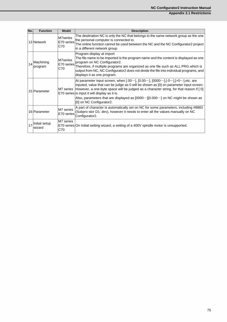
13 NetworkM7seriesE70 seriesC70
The destination NC is only the NC that belongs to the same network group as the one the personal computer is connected to.The online function cannot be used between the NC and the NC Configurator2 project in a different network group.
14 Machining program
M7seriesE70 seriesC70
Program display at import The file name to be imported is the program name and the content is displayed as one program on NC Configurator2.Therefore, if multiple programs are organized as one file such as ALL.PRG which is output from NC, NC Configurator2 does not divide the file into individual programs, and displays it as one program.
15 Parameter M7 seriesE70 series
At parameter input screen, when [.00…], [0.00…], [0000…],[-0…],[+0…],etc. are inputed, value that can be judge as 0 will be shown as [0] on parameter input screen. However, a one-byte space will be judged as a character string, for that reason if [ 0] is input it will display as it is.Also, parameters that are displayed as [0000…][0.000…] on NC might be shown as [0] on NC Configurator2.
16 Parameter M7 seriesE70 series
A part of character is automatically set on NC for some parameters, including #8883 (Subpro stor D1: dev), however it needs to enter all the values manually on NC Configurator2.
17 Initial setup wizard
M7 seriesE70 seriesC70
On Initial setting wizard, a setting of a 400V spindle motor is unsupported.
No. Function Model Description

Appendix 2 RestrictionsMITSUBISHI CNC
76

77
付録 Ap3 章
77
Appendix 3List of Error Messages
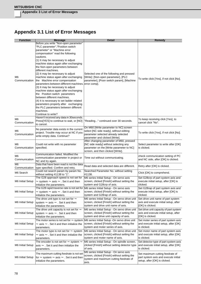
Appendix 3 List of Error MessagesMITSUBISHI CNC
78
Appendix 3.1 List of Error MessagesFunction Message Detail Remedy
M6 Communication
Before you write "Non-open parameter" "PLC parameter","Position switch parameter" or "Machine error compensation" read the following cautions.(1) It may be necessary to adjust machine status again after exchanging the Non-open parameters between different machines.(2) It may be necessary to adjust machine status again after exchanging the Machine error compensation parameters between different machines.(3) It may be necessary to adjust machine status again after exchanging the Position switch parameters between different machines.(4) It is necessary to set ladder related parameters properly after exchanging the PLC parameters between different machines.Continue to write?
Selected one of the following and pressed [Write]: [Non-open parameter], [PLC parameter], [Posn switch param], [Machine error comp].
To write click [Yes], if not click [No].
M6 Communication
Haven't received any data in 30seconds. Press[YES] to continue to wait, or [NO] to cancel.
"Reading..." continued over 30 seconds. To keep receiving click [Yes], to cancel click "No".
M6 Communication
No parameter data exists in the current project. Trouble may occur at NC if you write empty data. Continue?
On M60 [Write parameter to NC] screen select [NC side ready], without editing parameter selected already selected parameter and clicked [Write].
To write click [Yes], if not click [No].
M6 Communication
Could not write with no parameter specified.
After changing parameter of M60, pressed [NC side ready] without selecting any parameter on the [Write parameter to NC] screen, and then clicked [Write].
Select parameter to write after [OK] is clicked.
M6 Communication
Communication failed. Modified the communication parameter in project or NC and try again.
Time out without communicating. check communication setting of PC and NC side, after [OK] is clicked.
M6 Communication
Data that have been read is not the data type specified. Confirm and retry. Read data and selected data are different. Retry after [OK] is clicked.
M6 Search Could not search param by param No. without setting #1138 to "1".
Searched Parameter No. without setting #1138. Click [OK] to comprehend.
M6 Initial SetupThe G28 approach speed is not set for ~ system ~ axis ~ . Set it and then initialize the parameters.
M6 series Initial Setup - On servo axis screen, clicked [Finish] without setting the system and G28crp of axis.
Set G28crp of part system axis and execute initial setup, after [OK] is clicked.
M6 Initial SetupThe G28 rapid traverse rate is not set for ~ system ~ axis ~ . Set it and then initialize the parameters.
M6 series Initial Setup - On servo axis screen, clicked [Finish] without setting the system and G28rap of axis.
Set G28rap of part system axis and execute initial setup, after [OK] is clicked.
M6 Initial SetupThe drive unit type is not set for ~ system ~ axis ~ . Set it and then initialize the parameters.
M6 series Initial Setup - On servo drive unit screen, clicked [Finish] without setting the system and drive unit name of axis.
Set drive unit name of part system axis and execute initial setup, after [OK] is clicked.
M6 Initial SetupThe drive unit capacity is not set for ~ system ~ axis ~ . Set it and then initialize the parameters.
M6 series Initial Setup - On servo drive unit screen, clicked [Finish] without setting the system and drive unit capacity of axis.
Set drive unit capacity of part system axis and execute initial setup, after [OK] is clicked.
M6 Initial SetupThe motor series is not set for ~ system ~ axis ~ . Set it and then initialize the parameters.
M6 series Initial Setup -On servo drive unit screen, clicked [Finish] without setting the system and moter series of axis.
Set moter series of part system axis and execute initial setup, after [OK] is clicked.
M6 Initial SetupThe motor type is not set for ~ system ~ axis ~ . Set it and then initialize the parameters.
M6 series Initial Setup - On servo drive unit screen, clicked [Finish] without setting the system and moter name of axis.
Set motor name of part system axis and execute initial setup, after [OK] is clicked.
M6 Initial SetupThe encoder is not set for ~ system ~ axis ~ . Set it and then initialize the parameters.
M6 series Initial Setup - On spindle screen, clicked [Finish] without setting detector type of axis.
Set detector type of part system axis and execute initial setup, after [OK] is clicked.
M6 Initial SetupThe maximum cutting feedrate is not set for ~ system ~ axis ~ . Set it and then initialize the parameters.
M6 series Initial Setup - On servo axis screen, clicked [Finish] without setting the system and maximum cutting feedrate of axis.
Set maximum cutting feedrate of part system axis and execute initial setup, after [OK] is clicked.
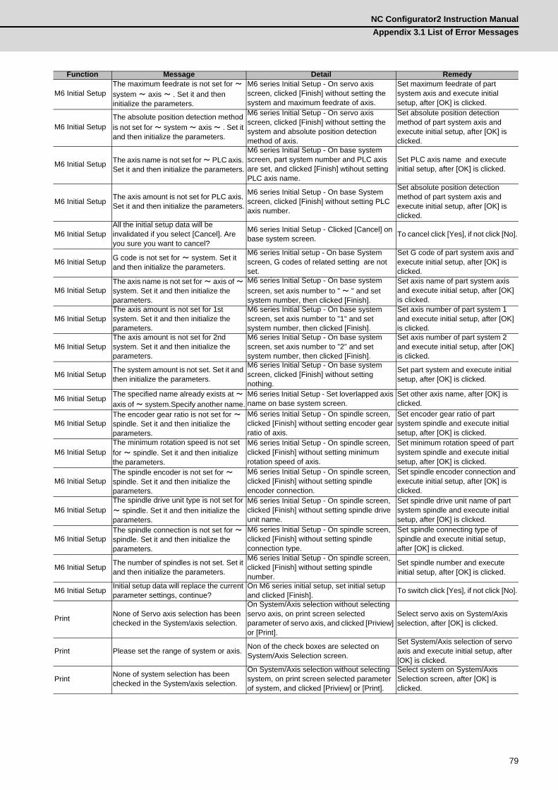
NC Configurator2 Instruction ManualAppendix 3.1 List of Error Messages
79
M6 Initial SetupThe maximum feedrate is not set for ~ system ~ axis ~ . Set it and then initialize the parameters.
M6 series Initial Setup - On servo axis screen, clicked [Finish] without setting the system and maximum feedrate of axis.
Set maximum feedrate of part system axis and execute initial setup, after [OK] is clicked.
M6 Initial SetupThe absolute position detection method is not set for ~ system ~ axis ~ . Set it and then initialize the parameters.
M6 series Initial Setup - On servo axis screen, clicked [Finish] without setting the system and absolute position detection method of axis.
Set absolute position detection method of part system axis and execute initial setup, after [OK] is clicked.
M6 Initial Setup The axis name is not set for ~ PLC axis. Set it and then initialize the parameters.
M6 series Initial Setup - On base system screen, part system number and PLC axis are set, and clicked [Finish] wtihout setting PLC axis name.
Set PLC axis name and execute initial setup, after [OK] is clicked.
M6 Initial Setup The axis amount is not set for PLC axis. Set it and then initialize the parameters.
M6 series Initial Setup - On base System screen, clicked [Finish] without setting PLC axis number.
Set absolute position detection method of part system axis and execute initial setup, after [OK] is clicked.
M6 Initial SetupAll the initial setup data will be invalidated if you select [Cancel]. Are you sure you want to cancel?
M6 series Initial Setup - Clicked [Cancel] on base system screen. To cancel click [Yes], if not click [No].
M6 Initial Setup G code is not set for ~ system. Set it and then initialize the parameters.
M6 series Initial setup - On base System screen, G codes of related setting are not set.
Set G code of part system axis and execute initial setup, after [OK] is clicked.
M6 Initial SetupThe axis name is not set for ~ axis of ~ system. Set it and then initialize the parameters.
M6 series Initial Setup - On base system screen, set axis number to " ~ " and set system number, then clicked [Finish].
Set axis name of part system axis and execute initial setup, after [OK] is clicked.
M6 Initial SetupThe axis amount is not set for 1st system. Set it and then initialize the parameters.
M6 series Initial Setup - On base system screen, set axis number to "1" and set system number, then clicked [Finish].
Set axis number of part system 1 and execute initial setup, after [OK] is clicked.
M6 Initial SetupThe axis amount is not set for 2nd system. Set it and then initialize the parameters.
M6 series Initial Setup - On base system screen, set axis number to "2" and set system number, then clicked [Finish].
Set axis number of part system 2 and execute initial setup, after [OK] is clicked.
M6 Initial Setup The system amount is not set. Set it and then initialize the parameters.
M6 series Initial Setup - On base system screen, clicked [Finish] without setting nothing.
Set part system and execute initial setup, after [OK] is clicked.
M6 Initial Setup The specified name already exists at ~ axis of ~ system.Specify another name.
M6 series Initial Setup - Set loverlapped axis name on base system screen.
Set other axis name, after [OK] is clicked.
M6 Initial SetupThe encoder gear ratio is not set for ~ spindle. Set it and then initialize the parameters.
M6 series Initial Setup - On spindle screen, clicked [Finish] without setting encoder gear ratio of axis.
Set encoder gear ratio of part system spindle and execute initial setup, after [OK] is clicked.
M6 Initial SetupThe minimum rotation speed is not set for ~ spindle. Set it and then initialize the parameters.
M6 series Initial Setup - On spindle screen, clicked [Finish] without setting minimum rotation speed of axis.
Set minimum rotation speed of part system spindle and execute initial setup, after [OK] is clicked.
M6 Initial SetupThe spindle encoder is not set for ~ spindle. Set it and then initialize the parameters.
M6 series Initial Setup - On spindle screen, clicked [Finish] without setting spindle encoder connection.
Set spindle encoder connection and execute initial setup, after [OK] is clicked.
M6 Initial SetupThe spindle drive unit type is not set for ~ spindle. Set it and then initialize the parameters.
M6 series Initial Setup - On spindle screen, clicked [Finish] without setting spindle drive unit name.
Set spindle drive unit name of part system spindle and execute initial setup, after [OK] is clicked.
M6 Initial SetupThe spindle connection is not set for ~ spindle. Set it and then initialize the parameters.
M6 series Initial Setup - On spindle screen, clicked [Finish] without setting spindle connection type.
Set spindle connecting type of spindle and execute initial setup, after [OK] is clicked.
M6 Initial Setup The number of spindles is not set. Set it and then initialize the parameters.
M6 series Initial Setup - On spindle screen, clicked [Finish] without setting spindle number.
Set spindle number and execute initial setup, after [OK] is clicked.
M6 Initial Setup Initial setup data will replace the current parameter settings, continue?
On M6 series initial setup, set initial setup and clicked [Finish]. To switch click [Yes], if not click [No].
Print None of Servo axis selection has been checked in the System/axis selection.
On System/Axis selection without selecting servo axis, on print screen selected parameter of servo axis, and clicked [Priview] or [Print].
Select servo axis on System/Axis selection, after [OK] is clicked.
Print Please set the range of system or axis. Non of the check boxes are selected on System/Axis Selection screen.
Set System/Axis selection of servo axis and execute initial setup, after [OK] is clicked.
Print None of system selection has been checked in the System/axis selection.
On System/Axis selection without selecting system, on print screen selected parameter of system, and clicked [Priview] or [Print].
Select system on System/Axis Selection screen, after [OK] is clicked.
Function Message Detail Remedy
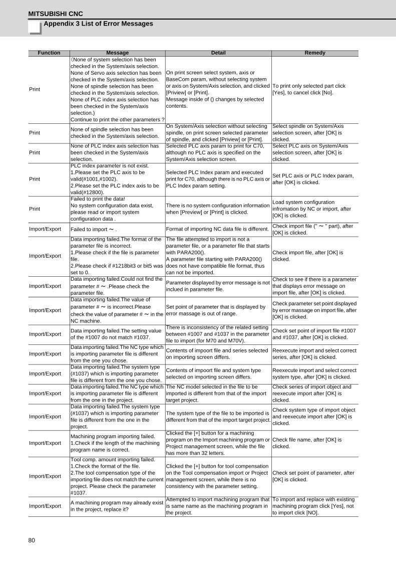
Appendix 3 List of Error MessagesMITSUBISHI CNC
80
(None of system selection has been checked in the System/axis selection.None of Servo axis selection has been checked in the System/axis selection.None of spindle selection has been checked in the System/axis selection.None of PLC index axis selection has been checked in the System/axis selection.)Continue to print the other parameters ?
On print screen select system, axis or BaseCom param, without selecting system or axis on System/Axis selection, and clicked [Priview] or [Print].Message inside of () changes by selected contents.
To print only selected part click [Yes], to cancel click [No].
Print None of spindle selection has been checked in the System/axis selection.
On System/Axis selection without selecting spindle, on print screen selected parameter of spindle, and clicked [Priview] or [Print].
Select spindle on System/Axis selection screen, after [OK] is clicked.
PrintNone of PLC index axis selection has been checked in the System/axis selection.
Selected PLC axis param to print for C70, although no PLC axis is specified on the System/Axis selection screen.
Select PLC axis on System/Axis selection screen, after [OK] is clicked.
PLC index parameter is not exist. 1.Please set the PLC axis to be valid(#1001,#1002).2.Please set the PLC index axis to be valid(#12800).
Selected PLC Index param and executed print for C70, although there is no PLC axis or PLC Index param setting.
Set PLC axis or PLC Index param, after [OK] is clicked.
Failed to print the data!No system configuration data exist, please read or import system configuration data .
There is no system configuration information when [Preview] or [Print] is clicked.
Load system configuration infromation by NC or import, after [OK] is clicked.
Import/Export Failed to import ~ . Format of importing NC data file is different. Check import file (" ~ " part), after [OK] is clicked.
Import/Export
Data importing failed.The format of the parameter file is incorrect.1.Please check if the file is parameter file.2.Please check if #1218bit3 or bit5 was set to 0.
The file attempted to import is not a parameter file, or a parameter file that starts with PARA200().A parameter file starting with PARA200() does not have compatible file format, thus can not be imported.
Check import file, after [OK] is clicked.
Import/ExportData importing failed.Could not find the parameter # ~ .Please check the parameter file.
Parameter displayed by error message is not inclued in parameter file.
Check to see if there is a parameter that displays error message on import file, after [OK] is clicked.
Import/Export
Data importing failed.The value of parameter # ~ is incorrect.Please check the value of parameter # ~ in the NC machine.
Set point of parameter that is displayed by error massage is out of range.
Check parameter set point displayed by error massage on import file, after [OK] is clicked.
Import/Export Data importing failed.The setting value of the #1007 do not match #1037.
There is inconsistency of the related setting between #1007 and #1037 in the parameter file to import (for M70 and M70V).
Check set point of import file #1007 and #1037, after [OK] is clicked.
Import/ExportData importing failed.The NC type which is importing parameter file is different from the one you chose.
Contents of impoort file and series selected on importing screen differs.
Reexecute import and select correct series, after [OK] is clicked.
Import/ExportData importing failed.The system type (#1037) which is importing parameter file is different from the one you chose.
Contents of impoort file and system type selected on importing screen differs.
Reexecute import and select correct system type, after [OK] is clicked.
Import/ExportData importing failed.The NC type which is importing parameter file is different from the one in the project.
The NC model selected in the file to be imported is different from that of the import target project.
Check series of import object and reexecute import after [OK] is clicked.
Import/Export
Data importing failed.The system type (#1037) which is importing parameter file is different from the one in the project.
The system type of the file to be imported is different from that of the import target project.
Check system type of import object and reexecute import after [OK] is clicked.
Import/ExportMachining program importing failed.1.Check if the length of the machining program name is correct.
Clicked the [+] button for a machining program on the Import machining program or Project management screen, while the file has more than 32 letters.
Check file name, after [OK] is clicked.
Import/Export
Tool comp. amount importing failed.1.Check the format of the file.2.The tool compensation type of the importing file does not match the current project. Please check the parameter #1037.
Clicked the [+] button for tool compensation on the Tool compensation import or Project management screen, while there is no consistency with the parameter setting.
Check set point of parameter, after [OK] is clicked.
Import/Export A machining program may already exist in the project, replace it?
Attempted to import machining program that is same name as the machining program in the project.
To import and replace with existing machining program click [Yes], not to import click [NO].
Function Message Detail Remedy
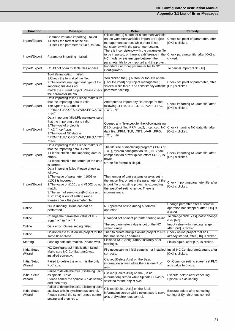
NC Configurator2 Instruction ManualAppendix 3.1 List of Error Messages
81
Import/ExportCommon variable importing failed.1.Check the format of the file.2.Check the parameter #1316, #1336.
Clicked the [+] button for a common variable on the Common variables import or Project management screen, while there is no consistency with the parameter setting.
Check set point of parameter, after [OK] is clicked.
Import/Export Parameter importing failed.
There is inconsistency with the parameter file to be imported, or there is a difference in the NC model or system type between the parameter file to be imported and the project.
Check parameter file, after [OK] is clicked.
Import/Export Could not open multiple files at once. Imported 2 or more parameter file to NC Configurator2. To cancel import click [OK].
Import/Export
Tool life importing failed.1.Check the format of the file.2.The tool life management type of the importing file does notmatch the current project. Please check the parameter #1096.
You clicked the [+] button for tool life on the [Tool life imort] or [Project management] screen, while there is no consistency with the parameter setting.
Check set point of parameter, after [OK] is clicked.
Import/Export
Data importing failed.Please make sure that the importing data is valid.The type of NC data is *.PRM,*.TLF,*.OFS,*.VAR,*.PRG,*.TXT,*.INF.
Attempted to import any file except for the following: .PRM, .TLF, .OFS, .VAR, .PRG, .TXT, .INF
Check importing NC data file, after [OK] is clicked.
Import/Export
Data importing failed.Please make sure that the importing data is valid.1.The type of project is *.nc2,*.ncp,*.cpg.2.The type of NC data is *.PRM,*.TLF,*.OFS,*.VAR,*.PRG,*.TXT,*.INF.
Opened any file except for the following using D&D: project file, .PRM, .nc2, .ncp, .cpg, NC data file, .PRM, .TLF, .OFS, .VAR, .PRG, .TXT, .INF
Check importing NC data file, after [OK] is clicked.
Import/Export
Data importing failed.Please make sure that the importing data is valid.1.Please check if the importing data is empty.2.Please check if the format of the data is correct.
The file size of machining program (.PRG or .TXT), system configuration file (.INF), tool compensation or workpiece offset (.OFS) is 0byte.Or the file format is illegal.
Check importing NC data file, after [OK] is clicked.
Import/Export
Data importing failed.Please check as follows:1.The value of parameter #1001 or #1002 is incorrect.2.The value of #1001 and #1002 do not match.3.The sum of servo axes(NC axis and PLC axis) is out of setting range.Please check the parameter file.
The number of part systems or axes set in the import file, or set in the parameter of the import file or existing project, is exceeding the specified setting range. There is inconsistency.
Check importing parameter file, after [OK] is clicked.
Online NC is running.Online can not be performed.
NC operated online during automatic operation.
Change paramter after automatic operation has stopped, after [OK] is clicked.
Online Change the parameter value of # ~ from [ ~ ] to [ ~ ] ?
Changed set point of paramter during online. To change click [Yes], not to change click [No].
Online Data error. Online setting failed. The set parameter value is out of the NC setting range.
Imput value within setting range, after [OK] is clicked.
Online Do not create multi online project for the same IP address.
Tried to create multiple online project to NC that has same IP address.
Check online project that has already started, after [OK] is clicked.
Starting Loading help information. Please wait. Finished NC Configurator2 instantly after starting it. Finish again, after [OK] is clicked.
Initial Setup Wizard
NC Configurator2 initialization failed. Make sure NC Configurator2 was installed correctly.
File necessary to initial setup is not installed correctly.
Install NC Configurator2 again, after [OK] is clicked.
Initial Setup Wizard
Failed to delete the axis. It is the only PLC axis.
Clicked [Delete Axis] on the Basic information screen while there is one PLC axis.
On Common setting screen set PLC axis value to 0 axis.
Initial Setup Wizard
Failed to delete the axis. It is being used as spindle C axis.Please cancel the spindle C axis setting and then retry.
Clicked [Delete Axis] on the [Basic information] screen while Spindle/C Axis is selected for the object axis.
Execute delete after canceling Spindle C axis setting.
Initial Setup Wizard
Failed to delete the axis. It is being used as slave axis in synchronous control.Please cancel the synchronous control setting and then retry.
Clicked [Delete Axis] on the Basic information screen while object axis is slave axis of Synchronous control.
Execute delete after canceling setting of Synchronous control.
Function Message Detail Remedy
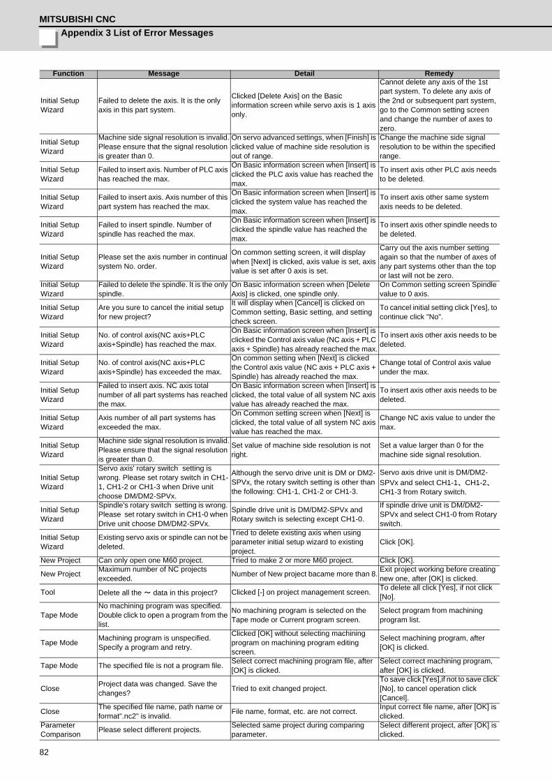
Appendix 3 List of Error MessagesMITSUBISHI CNC
82
Initial Setup Wizard
Failed to delete the axis. It is the only axis in this part system.
Clicked [Delete Axis] on the Basic information screen while servo axis is 1 axis only.
Cannot delete any axis of the 1st part system. To delete any axis of the 2nd or subsequent part system, go to the Common setting screen and change the number of axes to zero.
Initial Setup Wizard
Machine side signal resolution is invalid.Please ensure that the signal resolution is greater than 0.
On servo advanced settings, when [Finish] is clicked value of machine side resolution is out of range.
Change the machine side signal resolution to be within the specified range.
Initial Setup Wizard
Failed to insert axis. Number of PLC axis has reached the max.
On Basic information screen when [Insert] is clicked the PLC axis value has reached the max.
To insert axis other PLC axis needs to be deleted.
Initial Setup Wizard
Failed to insert axis. Axis number of this part system has reached the max.
On Basic information screen when [Insert] is clicked the system value has reached the max.
To insert axis other same system axis needs to be deleted.
Initial Setup Wizard
Failed to insert spindle. Number of spindle has reached the max.
On Basic information screen when [Insert] is clicked the spindle value has reached the max.
To insert axis other spindle needs to be deleted.
Initial Setup Wizard
Please set the axis number in continual system No. order.
On common setting screen, it will display when [Next] is clicked, axis value is set, axis value is set after 0 axis is set.
Carry out the axis number setting again so that the number of axes of any part systems other than the top or last will not be zero.
Initial Setup Wizard
Failed to delete the spindle. It is the only spindle.
On Basic information screen when [Delete Axis] is clicked, one spindle only.
On Common setting screen Spindle value to 0 axis.
Initial Setup Wizard
Are you sure to cancel the initial setup for new project?
It will display when [Cancel] is clicked on Common setting, Basic setting, and setting check screen.
To cancel initial setting click [Yes], to continue click "No".
Initial Setup Wizard
No. of control axis(NC axis+PLC axis+Spindle) has reached the max.
On Basic information screen when [Insert] is clicked the Control axis value (NC axis + PLC axis + Spindle) has already reached the max.
To insert axis other axis needs to be deleted.
Initial Setup Wizard
No. of control axis(NC axis+PLC axis+Spindle) has exceeded the max.
On common setting when [Next] is clicked the Control axis value (NC axis + PLC axis + Spindle) has already reached the max.
Change total of Control axis value under the max.
Initial Setup Wizard
Failed to insert axis. NC axis total number of all part systems has reached the max.
On Basic information screen when [Insert] is clicked, the total value of all system NC axis value has already reached the max.
To insert axis other axis needs to be deleted.
Initial Setup Wizard
Axis number of all part systems has exceeded the max.
On Common setting screen when [Next] is clicked, the total value of all system NC axis value has reached the max.
Change NC axis value to under the max.
Initial Setup Wizard
Machine side signal resolution is invalid.Please ensure that the signal resolution is greater than 0.
Set value of machine side resolution is not right.
Set a value larger than 0 for the machine side signal resolution.
Initial Setup Wizard
Servo axis' rotary switch setting is wrong. Please set rotary switch in CH1-1, CH1-2 or CH1-3 when Drive unit choose DM/DM2-SPVx.
Although the servo drive unit is DM or DM2-SPVx, the rotary switch setting is other than the following: CH1-1, CH1-2 or CH1-3.
Servo axis drive unit is DM/DM2-SPVx and select CH1-1、CH1-2、CH1-3 from Rotary switch.
Initial Setup Wizard
Spindle's rotary switch setting is wrong. Please set rotary switch in CH1-0 when Drive unit choose DM/DM2-SPVx.
Spindle drive unit is DM/DM2-SPVx and Rotary switch is selecting except CH1-0.
If spindle drive unit is DM/DM2-SPVx and select CH1-0 from Rotary switch.
Initial Setup Wizard
Existing servo axis or spindle can not be deleted.
Tried to delete existing axis when using parameter initial setup wizard to existing project.
Click [OK].
New Project Can only open one M60 project. Tried to make 2 or more M60 project. Click [OK].
New Project Maximum number of NC projects exceeded. Number of New project bacame more than 8. Exit project working before creating
new one, after [OK] is clicked.
Tool Delete all the ~ data in this project? Clicked [-] on project management screen. To delete all click [Yes], if not click [No].
Tape ModeNo machining program was specified. Double click to open a program from the list.
No machining program is selected on the Tape mode or Current program screen.
Select program from machining program list.
Tape Mode Machining program is unspecified. Specify a program and retry.
Clicked [OK] without selecting machining program on machining program editing screen.
Select machining program, after [OK] is clicked.
Tape Mode The specified file is not a program file. Select correct machining program file, after [OK] is clicked.
Select correct machining program, after [OK] is clicked.
Close Project data was changed. Save the changes? Tried to exit changed project.
To save click [Yes],if not to save click [No], to cancel operation click [Cancel].
Close The specified file name, path name or format".nc2" is invalid. File name, format, etc. are not correct. Input correct file name, after [OK] is
clicked.Parameter Comparison Please select different projects. Selected same project during comparing
parameter.Select different project, after [OK] is clicked.
Function Message Detail Remedy
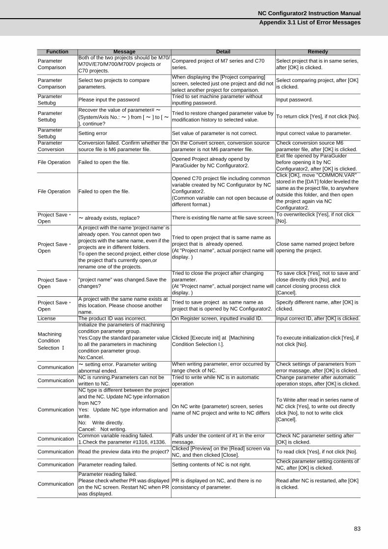
NC Configurator2 Instruction ManualAppendix 3.1 List of Error Messages
83
Parameter Comparison
Both of the two projects should be M70/M70V/E70/M700/M700V projects or C70 projects.
Compared project of M7 series and C70 series.
Select project that is in same series, after [OK] is clicked.
Parameter Comparison
Select two projects to compare parameters.
When displaying the [Project comparing] screen, selected just one project and did not select another project for comparison.
Select comparing project, after [OK] is clicked.
Parameter Settubg Please input the password Tried to set machine parameter without
inputting password. Input password.
Parameter Settubg
Recover the value of parameter# ~ (System/Axis No.: ~ ) from [ ~ ] to [ ~ ], continue?
Tried to restore changed parameter value by modification history to selected value. To return click [Yes], if not click [No].
Parameter Settubg Setting error Set value of parameter is not correct. Input correct value to parameter.
Parameter Conversion
Conversion failed. Confirm whether the source file is M6 parameter file.
On the Convert screen, conversion source parameter is not M6 parameter file.
Check conversion source M6 parameter file, after [OK] is clicked.
File Operation Failed to open the file. Opened Project already opend by ParaGuider by NC Configurator2.
Exit file opened by ParaGuider before opening it by NC Configurator2, after [OK] is clicked.
File Operation Failed to open the file.
Opened C70 project file including common variable created by NC Configurator by NC Configurator2.(Common variable can not open because of different format.)
Click [OK], move "COMMON.VAR" stored in the [DAT] folder leveled the same as the project file, to anywhere outside this folder, and then open the project again via NC Configurator2.
Project Save・Open ~ already exists, replace? There is existing file name at file save screen. To overwriteclick [Yes], if not click
[No].
Project Save・Open
A project with the name 'project name' is already open. You cannot open two projects with the same name, even if the projects are in different folders.To open the second project, either close the project that's currently open,or rename one of the projects.
Tried to open project that is same name as project that is already opened. (At "Project name", actual poroject name will display. )
Close same named project before opening the project.
Project Save・Open
"project name" was changed.Save the changes?
Tried to close the project after changing parameter.(At "Project name", actual poroject name will display. )
To save click [Yes], not to save and close directly click [No], and to cancel closing process click [Cancel].
Project Save・Open
A project with the same name exists at this location. Please choose another name.
Tried to save project as same name as project that is opened by NC Configurator2.
Specify different name, after [OK] is clicked.
License The product ID was incorrect. On Register screen, inputted invalid ID. Input correct ID, after [OK] is clicked.
Machining Condition Selection Ⅰ
Initialize the parameters of machining condition parameter group.Yes:Copy the standard parameter value to all the parameters in machining condition parameter group.No:Cancel.
Clicked [Execute init] at [Machining Condition Selection I.].
To execute initialization click [Yes], if not click [No].
Communication ~ setting error. Parameter writing abnormal ended.
When writing parameter, error occurred by range check of NC.
Check settings of parameters from error massage, after [OK] is clicked.
Communication NC is running.Parameters can not be written to NC.
Tried to write while NC is in automatic operation
Change parameter after automatic operation stops, after [OK] is clicked.
Communication
NC type is different between the project and the NC. Update NC type information from NC?Yes: Update NC type information and write.No: Write directly.Cancel: Not writing.
On NC write (parameter) screen, series name of NC project and write to NC differs
To Write after read in series name of NC click [Yes], to write out directly click [No], to not to write click [Cancel].
Communication Common variable reading failed.1.Check the parameter #1316, #1336.
Falls under the content of #1 in the error message.
Check NC parameter setting after [OK] is clicked.
Communication Read the preview data into the project? Clicked [Preview] on the [Read] screen via NC, and then clicked [Close]. To read click [Yes], if not click [No].
Communication Parameter reading failed. Setting contents of NC is not right. Check parameter setting contents of NC, after [OK] is clicked.
Communication
Parameter reading failed.Please check whether PR was displayed on the NC screen. Restart NC when PR was displayed.
PR is displayed on NC, and there is no consistancy of parameter.
Read after NC is restarted, afte [OK] is clicked.
Function Message Detail Remedy

Appendix 3 List of Error MessagesMITSUBISHI CNC
84
Communication
Parameter reading failed.The value of parameter # ~ is incorrect.Please check the value of parameter #~ in the NC machine.
On NC there is no consistancy of parameter Check setting value of object parameter of NC, after [OK] is clicked.
Communication
Tool life reading failed.1.The tool life management type of the project may do not match NC side.Please check the parameter #1096.
Corresponds to contents of 1 in error message.
Check setting value of object parameter of NC, after [OK] is clicked.
Communication
Tool comp. amount reading failed.1.The tool compensation type of the project may do not match NC side.Please check the parameter #1037.2.Check if any necessary #1013 or #1003 is unspecified at NC side. Set all and then retry.
Corresponds to contents of 1 and 2 in error message.
Check setting value of object parameter of NC, after [OK] is clicked.
Communication Writing data now. End now? Canceled writing during serial communication. To cancel click [Yes], if not click [No].
Communication No file selected. Select the file to write and try again.
Clicked [Send] without selecting a file to send on the Send text screen of Standard RS232C communication.
Select wirte file before reexecuting, after [OK] is clicked.
CommunicationThe NC to communicate is unspecified. Select a NC by communication setting now?
On Read from NC to Write to NC screen, clicked read or write without setting communication settings.
To specify click [Yes], if not click [No].
Communication
Communication failed. Check the following items and then try again.1. The NC is running normally?2. NC is connected to computer correctly?3. #6451/bit5 and #8109 is set to "0" at the NC? 4. NC side communication parameters are set to standard values?5. The communication port and baud rate of the computer have been specified correctly?
Communication failed in M60S.(when NC communication test continued over 60 sec. after you clicked [Communication test] on the Serial communication screen of Communication settings)
Check communication settings, after [OK] is clicked.
Communication Communication test failed The connection test with the selected NC has failed on the Communication settings screen.
Restart communication settings screen and select NC again and execute test.
Communication
Communication failed.1.Please check if the IP address exists.2.Please check the communication cable.3.Please check the power of the NC.4.Please check if the data of NC is protected(KEY1/KEY2/KEY3).( ※ 1)5.Please check if the connect pattern is corrected.( ※ 1)6.Please check if the communication settings is corrected.( ※ 1)
Failed to communicate. ( ※ 1) is displayed only on C70.
Check connection state after [OK] is clicked.
Communication
Communication failed.1.Please check if the IP address exists.2.Please check the communication cable.3.Please check the power of the NC.
Failed to communicate to online connection. Check connection state after [OK] is clicked.
Communication
Parameter reading failed because the NC type or system type of the parameter file is different from the one in the project.But M70 and M70V/E70,M700 and M700V with the same system type can communicate.
(1) The NC models selected by NC and NC Configurator2 are different. (possible to communicate between M70 and M70V, or between M700 and M700V)(2) The system types selected by NC and NC Configurator2 are different.In the case (1) or (2) as stated above, you clicked [Preview] or [Read] on the Read screen.
(1) Click [OK] and check the NC models and system types of NC and NC Configurator2.
Function Message Detail Remedy
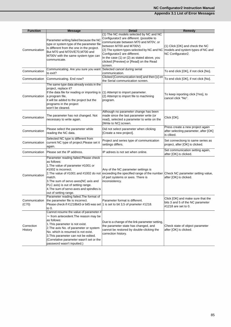
NC Configurator2 Instruction ManualAppendix 3.1 List of Error Messages
85
Communication
Parameter writing failed because the NC type or system type of the parameter file is different from the one in the project.But M70 and M70V/E70,M700 and M700V with the same system type can communicate.
(1) The NC models selected by NC and NC Configurator2 are different. (possible to communicate between M70 and M70V, or between M700 and M700V)(2) The system types selected by NC and NC Configurator2 are different.In the case (1) or (2) as stated above, you clicked [Preview] or [Read] on the Read screen.
(1) Click [OK] and check the NC models and system types of NC and NC Configurator2.
Communication Communicating. Are you sure you want to exit?
Selected cancel during serial communication. To end click [OK], if not click [No].
Communication Communicating. End now? Clicked [Communication test] and then [x] on the Serial communication screen. To end click [OK], if not click [No].
Communication
The same type data already exists in the project, replace it?If the data file for reading or importing is a program file, it will be added to the project but the programs in the projectwon't be cleared.
(1) Attempt to import parameter.(2) Attempt to import file to machining program.
To keep inporting click [Yes], to cancel click "No".
Communication The parameter has not changed. Not necessary to write again.
Although no parameter change has been made since the last parameter write (or read), selected a parameter to write on the [Write to NC] screen.
Click [OK].
Communication Please select the parameter while reading the NC data.
Did not select parameter when clicking [Create a new project].
Press create a new project again after selecting parameter, after [OK] is cliked.
CommunicationSelected NC type is different from current NC type of project.Please set it again.
Project and series type of communication settings differs.
Set connectiong to same series as project, after [OK] is clicked.
Communication Please set the IP address. IP adrees is not set when online. Set communication setting again, after [OK] is clicked.
Communication
Parameter reading failed.Please check as follows:1.The value of parameter #1001 or #1002 is incorrect.2.The value of #1001 and #1002 do not match.3.The sum of servo axes(NC axis and PLC axis) is out of setting range.4.The sum of servo axes and spindles is out of setting range.
Any of the NC parameter settings is exceeding the specified range of the number of part systems or axes. There is inconsistency.
Check NC parameter setting value, after [OK] is clicked.
Communication (C70)
Parameter reading failed.The format of the parameter file is incorrect.Please check if #1218bit3 or bit5 was set to 0.
Parameter format is different.1 is set to bit 3,5 of prameter #1218.
Click [OK] and make sure that the bits 3 and 5 of the NC parameter #1218 are set to 0.
Correction History
Cannot resume the value of parameter #~ from antecedent.The reason may be as follows:1.This parameter is not exist.2.The axis No. of parameter or system No. which is resumed is not exist.3.This parameter can not be edited. (Correlative parameter wasn't set or the password wasn't inputted.)
Due to a change of the link parameter setting, the parameter state has changed, and cannot be restored by double-clicking the correction history.
Check state of object parameter after [OK] is clicked.
Function Message Detail Remedy

Appendix 3 List of Error MessagesMITSUBISHI CNC
86

Index
AAdjustment Function ............................................... 56
CC70 Series Parameters...........................................37Common Variable Data Management.....................46Connection Configuration..........................................3Create a New Project (with Initial Setting)...............22Create a New Project (without Initial Setting)..........23Create a New Project ..............................................22
EExplanation of the Screen ....................................... 16Exporting the NC Parameters ................................. 30
FFile Function............................................................22First Time Installation Procedure ..............................6Function Parameter.................................................52
HHigh-speed High-accuracy (M60/M60S series) ...... 58High-speed High-accuracy (M7 series)................... 52
IImporting NC Data .................................................. 28Installation Procedure ...............................................6
LList of Error Messages ............................................ 78
MM60/M60S Series Parameters ................................39M7/E70 Series Parameters ..................................... 35Machine Information Management..........................33Machining Condition Selection I (M7 series)........... 53Machining Program Management ........................... 47Menu Configuration.................................................17
OOpen an Existing File ..............................................24Open an Online Project...........................................25Operation Flow........................................................ 15Outline of Functions ..................................................2Outline of NC Configurator2......................................2Output NC Parameter (csv file format).................... 31
PParameter Comparison........................................... 43Parameter Conversion............................................ 41Parameter Initial Setting ......................................... 62Parameter Management ......................................... 34Parameter Modification History............................... 40Parameter Search................................................... 40Preparation for PC side ............................................ 6Print ........................................................................ 32Project File.............................................................. 16Project Management............................................... 48
RRead and Write the NC Data .................................. 49Read From NC........................................................ 50Receiving Text ........................................................ 70Registration after installation .................................. 72Restrictions............................................................. 74Roundness (M60/M60S series) .............................. 56
SSaving a Project...................................................... 27Screen Configuration .............................................. 16Sending Text........................................................... 69Servo Adjustment (M60/M60S series) .................... 59Soft Limit (M7/E70 series, C70).............................. 54Standard RS232C Communication......................... 69Start NC Configurator2 ........................................... 14System Configuration Management ....................... 48System Requirements .............................................. 2
TTab.......................................................................... 19Tape Mode.............................................................. 68Thread Cutting (M7/E70 series).............................. 55Tool Compensation Data Management .................. 45Tool Life Data Management ................................... 44
UUninstall by Double-clicking on Setup.exe.............. 11Uninstall from the Control Panel ............................. 10Uninstall Procedure ................................................ 10Upgradeing Procedure.............................................. 9
WWizard Function...................................................... 62Workpiece Offset Data Management...................... 46Write To NC............................................................ 51


Revision History
Date of revision Manual No. Revision details
Jan. 2012 IB(NA)1501046-A First edition createdMay. 2013 IB(NA)1501046-B - Corresponded to S/W version A1.
- Corresponded to E70 series- Separated "4.12 Adjustment Function" to "4.12 Function Parameter" and "4.13 Adjustment function" then configured as below: 4.12 Function parameter 4.12.1 High-speed high-accuracy (M7 series) 4.12.2 Machining condition selection I (M7 series) 4.12.3 Soft limit (M7/E70 series,C70) 4.12.4 Thread cutting (M7/E70 series) 4.13 Adjustment Function 4.13.1 Roundness (M60/M60S series) 4.13.2 High-speed high-accuracy (M60/M60S series) 4.13.3 Servo Adjustment (M60/M60S series)- Added "Appendix 3 List of Error Messages".- Mistakes were corrected.

Global Service Network
AMERICA EUROPE
MITSUBISHI ELECTRIC AUTOMATION INC. (AMERICA FA CENTER) MITSUBISHI ELECTRIC EUROPE B.V. (EUROPE FA CENTER)Central Region Service Center GOTHAER STRASSE 10, 40880 RATINGEN, GERMANY 500 CORPORATE WOODS PARKWAY, VERNON HILLS, ILLINOIS 60061, U.S.A. TEL: +49-2102-486-0 / FAX: +49-2102-486-5910 TEL: +1-847-478-2500 / FAX: +1-847-478-2650
Germany Service CenterMichigan Service Satellite KURZE STRASSE. 40, 70794 FILDERSTADT-BONLANDEN, GERMANY ALLEGAN, MICHIGAN 49010, U.S.A. TEL: + 49-711-770598-121 / FAX: +49-711-770598-141 TEL: +1-847-478-2500 / FAX: +1-847-478-2650
France Service CenterOhio Service Satellite 25, BOULEVARD DES BOUVETS, 92741 NANTERRE CEDEX FRANCE LIMA, OHIO 45801, U.S.A. TEL: +33-1-41-02-83-13 / FAX: +33-1-49-01-07-25 TEL: +1-847-478-2500 / FAX: +1-847-478-2650 CINCINATTI, OHIO 45201, U.S.A. France (Lyon) Service Satellite TEL: +1-847-478-2500 / FAX: +1-847-478-2650 120, ALLEE JACQUES MONOD 69800 SAINT PRIEST FRANCE
TEL: +33-1-41-02-83-13 / FAX: +33-1-49-01-07-25Minnesota Service Satellite ROGERS, MINNESOTA 55374, U.S.A. Italy Service Center TEL: +1-847-478-2500 / FAX: +1-847-478-2650 VIALE COLLEONI, 7 - CENTRO DIREZIONALE COLLEONI PALAZZO SIRIO INGRESSO 1
20864 AGRATE BRIANZA (MB), ITALYWest Region Service Center TEL: +39-039-6053-342 / FAX: +39-039-6053-206 16900 VALLEY VIEW AVE., LAMIRADA, CALIFORNIA 90638, U.S.A. TEL: +1-714-699-2625 / FAX: +1-847-478-2650 Italy (Padova) Service Satellite
VIA G. SAVELLI, 24 - 35129 PADOVA, ITALYNorthern CA Satellite TEL: +39-039-6053-342 / FAX: +39-039-6053-206 SARATOGA, CALIFORNIA 95070, U.S.A. TEL: +1-714-699-2625 / FAX: +1-847-478-2650 U.K. Service Center
TRAVELLERS LANE, HATFIELD, HERTFORDSHIRE, AL10 8XB, U.K.East Region Service Center TEL: +44-1707-282-846 / FAX: +44-1707-27-8992 200 COTTONTAIL LANE SOMERSET, NEW JERSEY 08873, U.S.A. TEL: +1-732-560-4500 / FAX: +1-732-560-4531 Spain Service Center
CTRA. DE RUBI, 76-80-APDO. 420Pennsylvania Service Satellite 08190 SAINT CUGAT DEL VALLES, BARCELONA SPAIN ERIE, PENNSYLVANIA 16510, U.S.A. TEL: +34-935-65-2236 / FAX: +34-935-89-1579 TEL: +1-732-560-4500 / FAX: +1-732-560-4531
Poland Service CenterMassachusetts Service Satellite UL.KRAKOWSKA 50, 32-083 BALICE, POLAND Charlton, MA 01507, U.S.A. TEL: +48-12-630-4700 / FAX: +48-12-630-4701 TEL: +1-732-560-4500 / FAX: +1-732-560-4531
Turkey Service Center ŞERIFALI MAH. NUTUK SOK. NO.5 34775
South Region Service Center ÜMRANIYE / ISTANBUL, TURKEY 1845 SATTELITE BOULEVARD STE. 450, DULUTH, GEORGIA 30097, U.S.A. TEL: +90-216-526-3990 / FAX: +90-216-526-3995 TEL +1-678-258-4529 / FAX +1-678-258-4519
Czech Republic Service CenterTexas Service Satellites KAFKOVA 1853/3, 702 00 OSTRAVA 2, CZECH REPUBLIC GRAPEVINE, TEXAS 76051, U.S.A. TEL: +420-59-5691-185 / FAX: +420-59-5691-199 TEL: +1-678-258-4529 / FAX: +1-678-258-4519 HOUSTON, TEXAS 77001, U.S.A. Russia Service Center TEL: +1-678-258-4529 / FAX: +1-678-258-4519 213, B.NOVODMITROVSKAYA STR., 14/2, 127015 MOSCOW, RUSSIA
TEL: +7-495-748-0191 / FAX: +7-495-748-0192Tennessee Service Satellite Nashville, Tennessee, 37201, U.S.A. Sweden Service Center TEL: +1-678-258-4529 / FAX: +1-678-258-4519 STRANDKULLEN, 718 91 FRÖVI , SWEDEN
TEL: +46-581-700-20 / FAX: +46-581-700-75Florida Service Satellite WEST MELBOURNE, FLORIDA 32904, U.S.A. Bulgaria Service Center TEL: +1-678-258-4529 / FAX: +1-678-258-4519 4 ANDREJ LJAPCHEV BLVD. POB 21, BG-1756 SOFIA, BULGARIA
TEL: +359-2-8176009 / FAX: +359-2-9744061Canada Region Service Center 4299 14TH AVENUE MARKHAM, ONTARIO L3R OJ2, CANADA Ukraine (Kharkov) Service Center TEL: +1-905-475-7728 / FAX: +1-905-475-7935 APTEKARSKIY LANE 9-A, OFFICE 3, 61001 KHARKOV, UKRAINE
TEL: +380-57-732-7774 / FAX: +380-57-731-8721Canada Service Satellite EDMONTON, ALBERTA T5A 0A1, CANADA Ukraine (Kiev) Service Center TEL: +1-905-475-7728 FAX: +1-905-475-7935 4-B, M. RASKOVOYI STR., 02660 KIEV, UKRAINE
TEL: +380-44-494-3355 / FAX: +380-44-494-3366Mexico Region Service Center MARIANO ESCOBEDO 69 TLALNEPANTLA, 54030 EDO. DE MEXICO Belarus Service Center TEL: +52-55-3067-7500 / FAX: +52-55-9171-7649 Nezavisimosti pr.177, 220125 Minsk, Belarus
TEL: +375-17-393-1177 / FAX: +375-17-393-0081Monterrey Service Satellite MONTERREY, N.L., 64720, MEXICO South Africa Service Center TEL: +52-81-8365-4171 P.O. BOX 9234, EDLEEN, KEMPTON PARK GAUTENG, 1625 SOUTH AFRICA
TEL: +27-11-394-8512 / FAX: +27-11-394-8513
BRAZIL
MELCO CNC do Brasil Comércio e Serviços S.ABrazil Region Service Center ACESSO JOSE SARTORELLI, KM 2.1 CEP 18550-000, BOITUVA-SP, BRAZIL TEL: +55-15-3363-9900 / FAX: +55-15-3363-9911

ASEAN CHINA
MITSUBISHI ELECTRIC ASIA PTE. LTD. (ASEAN FA CENTER) MITSUBISHI ELECTRIC AUTOMATION (CHINA) LTD. (CHINA FA CENTER)Singapore Service Center China (Shanghai) Service Center 307 ALEXANDRA ROAD #05-01/02 MITSUBISHI ELECTRIC BUILDING SINGAPORE 159943 1-3,5-10,18-23/F, NO.1386 HONG QIAO ROAD, CHANG NING QU, TEL: +65-6473-2308 / FAX: +65-6476-7439 SHANGHAI 200336, CHINA
TEL: +86-21-2322-3030 / FAX: +86-21-2308-2830Malaysia (KL) Service Center China (Ningbo) Service Dealer 60, JALAN USJ 10 /1B 47620 UEP SUBANG JAYA SELANGOR DARUL EHSAN, MALAYSIA China (Wuxi) Service Dealer TEL: +60-3-5631-7605 / FAX: +60-3-5631-7636 China (Jinan) Service Dealer
China (Hangzhou) Service DealerMalaysia (Johor Baru) Service Center China (Wuhan) Service Satellite NO. 16, JALAN SHAH BANDAR 1, TAMAN UNGKU TUN AMINAH, 81300 SKUDAI, JOHOR MALAYSIA TEL: +60-7-557-8218 / FAX: +60-7-557-3404 China (Beijing) Service Center
9/F, OFFICE TOWER 1, HENDERSON CENTER, 18 JIANGUOMENNEI DAJIE,Philippines Service Center DONGCHENG DISTRICT, BEIJING 100005, CHINA UNIT NO.411, ALABAMG CORPORATE CENTER KM 25. WEST SERVICE ROAD TEL: +86-10-6518-8830 / FAX: +86-10-6518-3907 SOUTH SUPERHIGHWAY, ALABAMG MUNTINLUPA METRO MANILA, PHILIPPINES 1771 China (Beijing) Service Dealer TEL: +63-2-807-2416 / FAX: +63-2-807-2417
VIETNAM China (Tianjin) Service Center UNIT 2003, TIANJIN CITY TOWER, NO 35 YOUYI ROAD, HEXI DISTRICT,
MITSUBISHI ELECTRIC VIETNAM CO.,LTD TIANJIN 300061, CHINAVietnam (Ho Chi Minh) Service Center TEL: +86-22-2813-1015 / FAX: +86-22-2813-1017 UNIT 01-04, 10TH FLOOR, VINCOM CENTER 72 LE THANH TON STREET, DISTRICT 1, China (Shenyang) Service Satellite HO CHI MINH CITY, VIETNAM China (Changchun) Service Satellite TEL: +84-8-3910 5945 / FAX: +84-8-3910 5947
China (Chengdu) Service CenterVietnam (Hanoi) Service Satellite ROOM 407-408, OFFICE TOWER AT SHANGRI-LA CENTER, NO. 9 BINJIANG DONG ROAD, SUITE 9-05, 9TH FLOOR, HANOI CENTRAL OFFICE BUILDING, 44B LY THUONG KIET STREET, JINJIANG DISTRICT, CHENGDU, SICHUAN 610021, CHINA HOAN KIEM DISTRICT, HANOI CITY, VIETNAM TEL: +86-28-8446-8030 / FAX: +86-28-8446-8630 TEL: +84-4-3937-8075 / FAX: +84-4-3937-8076
China (Shenzhen) Service Center INDONESIA ROOM 2512-2516, 25/F., GREAT CHINA INTERNATIONAL EXCHANGE SQUARE, JINTIAN RD.S.,
FUTIAN DISTRICT, SHENZHEN 518034, CHINAPT. MITSUBISHI ELECTRIC INDONESIA TEL: +86-755-2399-8272 / FAX: +86-755-8218-4776Indonesia Service Center China (Xiamen) Service Dealer GEDUNG JAYA 11TH FLOOR, JL. MH. THAMRIN NO.12, JAKARTA PUSAT 10340, INDONESIA China (Dongguan) Service Dealer TEL: +62-21-3192-6461 / FAX: +62-21-3192-3942
THAILAND KOREA
MITSUBISHI ELECTRIC AUTOMATION (THAILAND) CO., LTD. (THAILAND FA CENTER) MITSUBISHI ELECTRIC AUTOMATION KOREA CO., LTD. (KOREA FA CENTER)Thailand Service Center Korea Service Center BANG-CHAN INDUSTRIAL ESTATE NO.111 SOI SERITHAI 54 1480-6, GAYANG-DONG, GANGSEO-GU, SEOUL 157-200, KOREA T.KANNAYAO, A.KANNAYAO, BANGKOK 10230, THAILAND TEL: +82-2-3660-9602 / FAX: +82-2-3664-8668 TEL: +66-2906-8255 / FAX: +66-2906-3239
Thailand Service Center Korea Taegu Service Satellite 898/19,20,21,22 S.V. CITY BUILDING OFFICE TOWER 1, FLOOR 7 4F KT BUILDING, 1630 SANGYEOK-DONG, BUK-KU, DAEGU 702-835, KOREA RAMA III RD., BANGPONGPANG, YANNAWA, BANGKOK 10120, THAILAND TEL: +82-53-382-7400 / FAX: +82-53-382-7411 TEL: +66-2-682-6522 / FAX: +66-2-682-9750
INDIA TAIWAN
MITSUBISHI ELECTRIC INDIA PVT. LTD. MITSUBISHI ELECTRIC TAIWAN CO., LTD. (TAIWAN FA CENTER)India Service Center Taiwan (Taichung) Service Center (Central Area) 2nd FLOOR, TOWER A & B, DLF CYBER GREENS, DLF CYBER CITY, NO.8-1, INDUSTRIAL 16TH RD., TAICHUNG INDUSTRIAL PARK, SITUN DIST., DLF PHASE-III, GURGAON 122 002, HARYANA, INDIA TAICHUNG CITY 40768, TAIWAN R.O.C. TEL: +91-124-4630 300 / FAX: +91-124-4630 399 TEL: +886-4-2359-0688 / FAX: +886-4-2359-0689 Ludhiana satellite office Jamshedpur satellite office Taiwan (Taipei) Service Center (North Area)
10F, NO.88, SEC.6, CHUNG-SHAN N. RD., SHI LIN DIST., TAIPEI CITY 11155, TAIWAN R.O.C.India (Pune) Service Center TEL: +886-2-2833-5430 / FAX: +886-2-2833-5433 EMERALD HOUSE, EL-3, J-BLOCK, MIDC BHOSARI. PUNE – 411 026, MAHARASHTRA, INDIA TEL: +91-20-2710 2000 / FAX: +91-20-2710 2100 Taiwan (Tainan) Service Center (South Area) Baroda satellite office 11F-1., NO.30, ZHONGZHENG S. ROAD, YONGKANG DISTRICT, TAINAN CITY 71067, TAIWAN, R.O.C Mumbai satellite office TEL: +886-6-252-5030 / FAX: +886-6-252-5031
India (Bangalore) Service Center PRESTIGE EMERALD, 6TH FLOOR, MUNICIPAL NO. 2, LAVELLE ROAD, BANGALORE - 560 043, KAMATAKA, INDIA TEL: +91-80-4020-1600 / FAX: +91-80-4020-1699 Chennai satellite office Coimbatore satellite office
OCEANIA
MITSUBISHI ELECTRIC AUSTRALIA LTD.Australia Service Center 348 VICTORIA ROAD, RYDALMERE, N.S.W. 2116 AUSTRALIA TEL: +61-2-9684-7269 / FAX: +61-2-9684-7245

Notice
Every effort has been made to keep up with software and hardware revisions in the contents described in this manual. However, please understand that in some unavoidable cases simultaneous revision is not possible. Please contact your Mitsubishi Electric dealer with any questions or comments regarding the use of this product.
Duplication Prohibited
This manual may not be reproduced in any form, in part or in whole, without written permission from Mitsubishi Electric Corporation.
COPYRIGHT 2012-2013 MITSUBISHI ELECTRIC CORPORATION ALL RIGHTS RESERVED
