ncma - danddcc.com · east building sprinkler and fire alarm replacements sco # 16-15676-01a code #...
TRANSCRIPT


NCMA EAST BUILDING SPRINKLER AND FIRE ALARM REPLACEMENTS SCO # 16-15676-01A CODE # 41501 ITEM # 4V16
TABLE OF CONTENTS TOC - 1
TABLE OF CONTENTS
-Cover Sheet -Seals Page -Table of Contents -Advertisement for Bids -Notice to Bidders -Instructions to Bidders and General Conditions of the Contract -Supplementary General Conditions -Guidelines for Recruitment and Selection of Minority Businesses Participation in State Construction Contracts
DIVISION 01 – GENERAL REQUIREMENTS 010100 Summary of Work 010300 Alternates and Unit Prices 010350 Modification Procedures 013000 Submittals 013233 Photographic Documentation 013400 Shop Drawings, Product Data and Samples 015000 Temporary Facilities 017000 Project Closeout 017300 Execution 017329 Cutting and Patching
DIVISION 02 – EXISTING CONDITIONS 024119 Selective Demolition
DIVISION 21 – FIRE SUPPRESSION 210500 Common Work Results for Fire Suppression 211000 Water-Based Fire-Suppression Systems
DIVISION 26 – ELECTRICAL 260500 Common Work Results for Electrical 260519 Low Voltage Electrical Power Conductors 260526 Grounding and Bonding for Electrical System 260529 Hangers and Supports for Electrical Systems 260533 Raceway and Boxes for Electrical Systems 260553 Identification for Electrical Systems
DIVISION 28 – ELECTRONIC SAFETY AND SECURITY 283111 Digital Addressable Fire Alarm System

NCMA EAST BUILDING SPRINKLER AND FIRE ALARM REPLACEMENTS SCO # 16-15676-01A CODE # 41501 ITEM # 4V16
TABLE OF CONTENTS TOC - 2
Form of Proposal Identification of Minority Business Participation Affidavit A - Listing of Good Faith Efforts Affidavit B - Intent to Perform Contract with Own Workforce Affidavit C - Portion of Work to be performed by Minority Firms Affidavit D - Good Faith Efforts Form of Bid Bond Form of Construction Contract Form of Performance Bond Form of Payment Bond Sheet for Attaching Power of Attorney Sheet for Attaching Certificate of Insurance Approval of the Attorney General

NCMA EAST BUILDING SPRINKLER AND FIRE ALARM REPLACEMENTS SCO # 16-15676-01A CODE # 41501 ITEM # 4V16
ADVERTISEMENT FOR BIDS 1
ADVERTISEMENT FOR BIDS Sealed proposals will be received by Robert Talley, PE, NORTH CAROLINA STATE CONSTRUCTION OFFICE-NC DEPARTMENT OF ADMINSTRATION Raleigh, NC., in the Large Conference Room at the North Carolina State Construction Office (301 N. Wilmington Street, Raleigh NC 27601), up to 2:00 pm Thursday February 8, 2018 and immediately thereafter publicly opened and read for the furnishing of labor, material and equipment entering into the construction of
NORTH CAROLINA MUSEUM OF ART EAST BUILDING SPRINKLER AND FIRE ALARM REPLACEMENTS
SCO # 16-15676-01A CODE # 41501 ITEM # 4V16 at which time and place bids will be opened and read. Complete plans and specifications for this project can be obtained from Sigma Engineered Solutions,
PC, 2100 Gateway Centre Blvd., Suite 100, Morrisville, NC 27560, (919) 840-9300 during normal
office hours after January 8, 2018.
Plan Deposit $250.00
The state reserves the unqualified right to reject any and all proposals.
Owner: Mr. Robert Talley, PE
North Carolina State Construction Office NC Dept. of Administration 301 N. Wilmington Street, Suite 450 Raleigh NC 27601


NCMA EAST BUILDING SPRINKLER AND FIRE ALARM REPLACEMENTS SCO # 16-15676-01A CODE # 41501 ITEM # 4V16
SCO-Notice To Bidders 2010 – (Updated Dec. 2010)
N O T I C E TO B I D D E R S
Sealed proposals will be received by Robert Talley, PE, NORTH CAROLINA STATE CONSTRUCTION OFFICE-NC DEPARTMENT OF ADMINSTRATION, Raleigh, NC., in the Large Conference Room at the North Carolina State Construction Office (301 N. Wilmington Street, Raleigh NC 27603), up to 2:00 pm Thursday February 8, 2018 and immediately thereafter publicly opened and read for the furnishing of labor, material and equipment entering into the construction of
NORTH CAROLINA MUSEUM OF ART EAST BUILDING SPRINKLER AND FIRE ALARM REPLACEMENTS
SCO # 16-15676-01A CODE # 41501 ITEM # 4V16
Bids will be received for SINGLE PRIME CONSTRUCTION CONTRACTS. All proposals shall be lump sum.
Pre-Bid Meeting A pre-bid meeting will be held for all interested bidders on Thursday January 18 2018 at 2:00 pm. at the North Carolina Museum of Art (2110 Blue Ridge Rd, Raleigh, NC 27607). The meeting will address project specific questions, issues, bidding procedures and bid forms. Attendance is STRONGLY ENCOURAGED. Complete plans, specifications and contract documents will be open for inspection in the offices of Sigma Engineered Solutions PC (2100 Gateway Centre Blvd, Suite 100 Morrisville NC 27560, (Phone 919-840-9300), and in the plan rooms of the Associated General Contractors, Carolinas Branch, Raleigh, NC, in the local North Carolina offices of McGraw-Hill Dodge Corporation, in the Eastern Regional Office of Reed Construction Data in Norcross, GA, and East Coast Digital – Minority Plan Room Provider 703 SE Greenville Blvd, Greenville, NC 27858, 252-758-1616 or may be obtained by those qualified as prime bidders, upon deposit of Two Hundred Fifty dollars ($250) in cash or certified check. The full plan deposit will be returned to those bidders provided all documents are returned in good, usable condition within ten (10) days after the bid date.
NOTE: The bidder shall include with the bid proposal the form Identification of Minority Business Participation identifying the minority business participation it will use on the project and shall include either Affidavit A or Affidavit B as applicable. Forms and instructions are included within the Proposal Form in the bid documents. Failure to complete these forms is grounds for rejection of the bid. (GS143-128.2c Effective 1/1/2002.) All contractors are hereby notified that they must have proper license as required under the state laws governing their respective trades. General contractors are notified that Chapter 87, Article 1, General Statutes of North Carolina, will be observed in receiving and awarding general contracts. General contractors submitting bids on this project must have license classification for Building Contractor (set forth the license classification required by the NC General Contractors Licensing Board under G.S. 87-1)
NOTE--SINGLE PRIME CONTRACTS: Under GS 87-1, a contractor that superintends or manages construction of any building, highway, public utility, grading, structure or improvement shall be deemed a “general contractor” and shall be so licensed. Therefore a single prime project that involves other trades will require the single prime contractor to hold a proper General Contractors license. EXCEPT: On public buildings being bid single prime, where the total value of the general

NCMA EAST BUILDING SPRINKLER AND FIRE ALARM REPLACEMENTS SCO # 16-15676-01A CODE # 41501 ITEM # 4V16
SCO-Notice To Bidders 2010 (Updated Dec. 2010)
construction does not exceed 25% of the total construction value, contractors under GS87- Arts 2 and 4 (Plumbing, Mechanical & Electrical) may bid and contract directly with the Owner as the SINGLE PRIME CONTRACTOR and may subcontract to other properly licensed trades. GS87-1.1- Rules .0210
Each proposal shall be accompanied by a cash deposit or a certified check drawn on some bank or trust company, insured by the Federal Deposit Insurance Corporation, of an amount equal to not less than five percent (5%) of the proposal, or in lieu thereof a bidder may offer a bid bond of five percent (5%) of the bid executed by a surety company licensed under the laws of North Carolina to execute the contract in accordance with the bid bond. Said deposit shall be retained by the owner as liquidated damages in event of failure of the successful bidder to execute the contract within ten days after the award or to give satisfactory surety as required by law. A performance bond and a payment bond will be required for one hundred percent (100%) of the contract price. Payment will be made based on ninety-five percent (95%) of monthly estimates and final payment made upon completion and acceptance of work. No bid may be withdrawn after the scheduled closing time for the receipt of bids for a period of 60 days. The owner reserves the right to reject any or all bids and to waive informalities. Designer: Owner:
Mr. Robert Talley, PE
Sigma Engineered Solutions, PC North Carolina State Construction Office 2100 Gateway Centre Blvd. Suite 100 NC Dept. of Administration Morrisvile, NC 27560 301 N. Wilmington Street, Suite 450 919-840-9300 Raleigh NC 27601

INSTRUCTIONS TO BIDDERS
AND
GENERAL CONDITIONS OF THE CONTRACT
STANDARD FORM FOR CONSTRUCTION PROJECTS
STATE CONSTRUCTION OFFICE
NORTH CAROLINA
DEPARTMENT OF ADMINISTRATION Form OC-15 This document is intended for use on State capital construction projects and shall not be used on any project that is not reviewed and approved by the State Construction Office. Extensive modification to the General Conditions by means of “Supplementary General Conditions” is strongly discouraged. State agencies and institutions may include special requirements in “Division 1 – General Requirements” of the specifications, where they do not conflict with the General Conditions. Twenty Fourth Edition January 2013

Page 2
INSTRUCTIONS TO BIDDERS For a proposal to be considered it must be in accordance with the following instructions: 1. PROPOSALS Proposals must be made in strict accordance with the Form of Proposal provided therefor, and
all blank spaces for bids, alternates, and unit prices applicable to bidder’s work shall be properly filled in. When requested alternates are not bid, the proposer shall so indicate by the words “No Bid”. Any blanks shall also be interpreted as “No Bid”.The bidder agrees that bid on Form of Proposal detached from specifications will be considered and will have the same force and effect as if attached thereto. Photocopied or faxed proposals will not be considered. Numbers shall be stated both in writing and in figures for the base bids and alternates. If figures and writing differ, the written number will supersede the figures.
Any modifications to the Form of Proposal (including alternates and/or unit prices) will
disqualify the bid and may cause the bid to be rejected. The bidder shall fill in the Form of Proposal as follows: a. If the documents are executed by a sole owner, that fact shall be evidenced by the word
"Owner" appearing after the name of the person executing them. b. If the documents are executed by a partnership, that fact shall be evidenced by the word
"Co-Partner" appearing after the name of the partner executing them. c. If the documents are executed on the part of a corporation, they shall be executed by
either the president or the vice president and attested by the secretary or assistant secretary in either case, and the title of the office of such persons shall appear after their signatures. The seal of the corporation shall be impressed on each signature page of the documents.
d. If the proposal is made by a joint venture, it shall be executed by each member of the joint
venture in the above form for sole owner, partnership or corporation, whichever form is applicable.
e. All signatures shall be properly witnessed. f. If the contractor's license of a bidder is held by a person other than an owner, partner or
officer of a firm, then the licensee shall also sign and be a party to the proposal. The title "Licensee" shall appear under his/her signature.
Proposals should be addressed as indicated in the Advertisement for Bids and be delivered,
enclosed in an opaque sealed envelope, marked "Proposal" and bearing the title of the work, name of the bidder, and the contractor’s license number of the bidder. Bidders should clearly mark on the outside of the bid envelope which contract(s) they are bidding.
Bidder shall identify on the bid, the minority businesses that will be utilized on the project with
corresponding total dollar value of the bid and affidavit listing good faith efforts or an affidavit indicating work under contract will be self-performed, as required by G.S. 143-128.2(c) and G.S. 143-128.2(f). Failure to comply with these requirements is grounds for rejection of the bid.

Page 3
For projects bid in the single-prime alternative, the names and license numbers of major subcontractors shall be listed on the proposal form.
It shall be the specific responsibility of the bidder to deliver his bid to the proper official at the
selected place and prior to the announced time for the opening of bids. Later delivery of a bid for any reason, including delivery by any delivery service, shall disqualify the bid.
Unit prices quoted in the proposal shall include overhead and profit and shall be the full
compensation for the contractor's cost involved in the work. See General Conditions, Article 19c-1.
2. EXAMINATION OF CONDITIONS It is understood and mutually agreed that by submitting a bid the bidder acknowledges that he
has carefully examined all documents pertaining to the work, the location, accessibility and general character of the site of the work and all existing buildings and structures within and adjacent to the site, and has satisfied himself as to the nature of the work, the condition of existing buildings and structures, the conformation of the ground, the character, quality and quantity of the material to be encountered, the character of the equipment, machinery, plant and any other facilities needed preliminary to and during prosecution of the work, the general and local conditions, the construction hazards, and all other matters, including, but not limited to, the labor situation which can in any way affect the work under the contract, and including all safety measures required by the Occupational Safety and Health Act of 1970 and all rules and regulations issued pursuant thereto. It is further mutually agreed that by submitting a proposal the bidder acknowledges that he has satisfied himself as to the feasibility and meaning of the plans, drawings, specifications and other contract documents for the construction of the work and that he accepts all the terms, conditions and stipulations contained therein; and that he is prepared to work in cooperation with other contractors performing work on the site.
Reference is made to contract documents for the identification of those surveys and
investigation reports of subsurface or latent physical conditions at the site or otherwise affecting performance of the work which have been relied upon by the designer in preparing the documents. The owner will make copies of all such surveys and reports available to the bidder upon request.
Each bidder may, at his own expense, make such additional surveys and investigations as he
may deem necessary to determine his bid price for the performance of the work. Any on-site investigation shall be done at the convenience of the owner. Any reasonable request for access to the site will be honored by the owner.
3. BULLETINS AND ADDENDA Any addenda to specifications issued during the time of bidding are to be considered covered
in the proposal and in closing a contract they will become a part thereof. It shall be the bidder’s responsibility to ascertain prior to bid time the addenda issued and to see that his bid includes any changes thereby required.
Should the bidder find discrepancies in, or omission from, the drawings or documents or
should he be in doubt as to their meaning, he shall at once notify the designer who will send written instructions in the form of addenda to all bidders. Notification should be no later than seven (7) days prior to the date set for receipt of bids. Neither the owner nor the designer will be responsible for any oral instructions.

Page 4
All addenda should be acknowledged by the bidder(s) on the Form of Proposal. However, even if not acknowledged, by submitting a bid, the bidder has certified that he has reviewed all issued addenda and has included all costs associated within his bid.
4. BID SECURITY Each proposal shall be accompanied by a cash deposit or a certified check drawn on some
bank or trust company insured by the Federal Deposit Insurance Corporation, or a bid bond in an amount equal to not less than five percent (5%) of the proposal, said deposit to be retained by the owner as liquidated damages in event of failure of the successful bidder to execute the contract within ten (10) days after the award or to give satisfactory surety as required by law (G.S. 143-129).
Bid bond shall be conditioned that the surety will, upon demand, forthwith make payment to
the obligee upon said bond if the bidder fails to execute the contract. The owner may retain bid securities of any bidder(s) who may have a reasonable chance of award of contract for the full duration of time stated in the Notice to Bidders. Other bid securities may be released sooner, at the discretion of the owner. All bid securities (cash or certified checks) shall be returned to the bidders promptly after award of contracts, and no later then seven (7) days after expiration of the holding period stated in the Notice to Bidders. Standard Form of Bid Bond is included in these specifications and shall be used.
5. RECEIPT OF BIDS Bids shall be received in strict accordance with requirements of the General Statutes of North
Carolina. Bid security shall be required as prescribed by statute. Prior to the closing of the bid, the bidder will be permitted to change or withdraw his bid. Guidelines for opening of public construction bids are available from the State Construction Office.
6. OPENING OF BIDS Upon opening, all bids shall be read aloud. Once bidding is closed, there shall not be any
withdrawal of bids by any bidder and no bids may be returned by the designer to any bidder. After the opening of bids, no bid may be withdrawn, except under the provisions of General Statute 143-129.1, for a period of thirty days unless otherwise specified. Should the successful bidder default and fail to execute a contract, the contract may be awarded to the next lowest and responsible bidder. The owner reserves the unqualified right to reject any and all bids. Reasons for rejection may include, but shall not be limited to, the following:
a. If the Form of Proposal furnished to the bidder is not used or is altered. b. If the bidder fails to insert a price for all bid items, alternate and unit prices requested. c. If the bidder adds any provisions reserving the right to accept or reject any award. d. If there are unauthorized additions or conditional bids, or irregularities of any kind which
tend to make the proposal incomplete, indefinite or ambiguous as to its meaning. e. If the bidder fails to complete the proposal form where information is requested so the bid
may be properly evaluated by the owner. f. If the unit prices contained in the bid schedule are unacceptable to the owner and the
State Construction Office. g. If the bidder fails to comply with other instructions stated herein.

Page 5
7. BID EVALUATION The award of the contract will be made to the lowest responsible bidder as soon as practical.
The owner may award on the basis of the base bid and any alternates the owner chooses. Before awarding a contract, the owner may require the apparent low bidder to qualify himself
to be a responsible bidder by furnishing any or all of the following data: a. The latest financial statement showing assets and liabilities of the company or other
information satisfactory to the owner. b. A listing of completed projects of similar size. c. Permanent name and address of place of business. d. The number of regular employees of the organization and length of time the organization
has been in business under present name. e. The name and home office address of the surety proposed and the name and address of
the responsible local claim agent. f. The names of members of the firms who hold appropriate trade licenses, together with
license numbers. g. If prequalified, contractor info will be reviewed and evaluated comparatively to submitted
prequalification package. Failure or refusal to furnish any of the above information, if requested, shall constitute a basis
for disqualification of any bidder. In determining the lowest responsible, responsive bidder, the owner shall take into
consideration the bidder’s compliance with the requirements of G.S. 143-128.2(c), the past performance of the bidder on construction contracts for the State with particular concern given to completion times, quality of work, cooperation with other contractors, and cooperation with the designer and owner. Failure of the low bidder to furnish affidavit and/or documentation as required by G.S. 143-128.2(c) shall constitute a basis for disqualification of the bid.
Should the owner adjudge that the apparent low bidder is not the lowest responsible,
responsive bidder by virtue of the above information, said apparent low bidder will be so notified and his bid security shall be returned to him.
8. PERFORMANCE BOND The successful bidder, upon award of contract, shall furnish a performance bond in an amount
equal to 100 percent of the contract price. See Article 35, General Conditions. 9. PAYMENT BOND The successful bidder, upon award of contract, shall furnish a payment bond in an amount
equal to 100 percent of the contract price. See Article 35, General Conditions.
Page 6
10. PAYMENTS Payments to the successful bidders (contractors) will be made on the basis of monthly
estimates. See Article 31, General Conditions. 11. PRE-BID CONFERENCE Prior to the date set for receiving bids, the Designer may arrange and conduct a Pre-Bid
Conference for all prospective bidders. The purpose of this conference is to review project requirements and to respond to questions from prospective bidders and their subcontractors or material suppliers related to the intent of bid documents. Attendance by prospective bidders shall be as required by the “Notice to Bidders”.
12. SUBSTITUTIONS
In accordance with the provisions of G.S. 133-3, material, product, or equipment substitutions proposed by the bidders to those specified herein can only be considered during the bidding phase until ten (10) days prior to the receipt of bids when submitted to the Designer with sufficient data to confirm material, product, or equipment equality. Proposed substitutions submitted after this time will be considered only as potential change order.
Submittals for proposed substitutions shall include the following information: a. Name, address, and telephone number of manufacturer and supplier as appropriate. b. Trade name, model or catalog designation. c. Product data including performance and test data, reference standards, and technical
descriptions of material, product, or equipment. Include color samples and samples of available finishes as appropriate.
d. Detailed comparison with specified products including performance capabilities,
warranties, and test results. e. Other pertinent data including data requested by the Designer to confirm product
equality. If a proposed material, product, or equipment substitution is deemed equal by the Designer to
those specified, all bidders of record will be notified by Addendum.
Page 7
GENERAL CONDITIONS OF THE CONTRACT The use or reproduction of this document or any part thereof is authorized for and limited to use on projects of the State of North Carolina, and is distributed by, through and at the discretion of the State Construction Office, Raleigh, North Carolina, for that distinct and sole purpose. TABLE OF CONTENTS ARTICLE TITLE PAGE 1 Definitions .................................................................................................................. 9 2 Intent and Execution of Documents ............................................................................ 11 3 Clarifications and Detail Drawings .............................................................................. 12 4 Copies of Drawings and Specifications ....................................................................... 12 5 Shop Drawings, Submittals, Samples, Data ................................................................. 13 6 Working Drawings and Specifications at the Job Site .................................................. 13 7 Ownership of Drawings and Specifications ................................................................. 14 8 Materials, Equipment, Employees ............................................................................... 14 9 Royalties, Licenses and Patent .................................................................................... 15 10 Permits, Inspections, Fees, Regulations ....................................................................... 15 11 Protection of Work, Property and the Public ............................................................... 16 12 Sedimentation Pollution Control Act of 1973 .............................................................. 17 13 Inspection of the Work ............................................................................................... 17 14 Construction Supervision and Schedule ....................................................................... 18 15 Separate Contracts and Contractor Relationships ........................................................ 22 16 Subcontracts and Subcontractors ................................................................................ 23 17 Contractor and Subcontractor Relationships ............................................................... 23 18 Designer's Status ........................................................................................................ 24 19 Changes in the Work .................................................................................................. 25 20 Claims for Extra Cost ................................................................................................. 27 21 Minor Changes in the Work ........................................................................................ 29 22 Uncorrected Faulty Work ........................................................................................... 29 23 Time of Completion, Delays, Extension of Time ......................................................... 29 24 Partial Utilization: Beneficial Occupancy .................................................................... 30 25 Final Inspection, Acceptance, and Project Closeout .................................................... 31 26 Correction of Work Before Final Payment .................................................................. 31 27 Correction of Work After Final Payment ..................................................................... 32 28 Owner's Right to Do Work ......................................................................................... 32 29 Annulment of Contract ............................................................................................... 32 30 Contractor's Right to Stop Work or Terminate the Contract ........................................ 33 31 Requests for Payments ................................................................................................ 33 32 Certificates of Payment and Final Payment .................................................................. 34 33 Payments Withheld ..................................................................................................... 36 34 Minimum Insurance Requirements .............................................................................. 36 35 Performance Bond and Payment Bond ........................................................................ 37 36 Contractor's Affidavit ................................................................................................. 38 37 Assignments ............................................................................................................... 38 38 Use of Premises .......................................................................................................... 38 39 Cutting, Patching and Digging .................................................................................... 38 40 Utilities, Structures, Signs ........................................................................................... 38 41 Cleaning Up ................................................................................................................ 40 42 Guarantee ................................................................................................................... 41

Page 8
43 Codes and Standards ............................................................................................... … 41 44 Indemnification ........................................................................................................ … 41 45 Taxes ...................................................................................................................... … 41 46 Equal Opportunity Clause ........................................................................................ … 42 47 Employment of the Handicapped ............................................................................. … 42 48 Asbestos-Containing Materials (ACM) .................................................................... … 43 49 Minority Business Participation ............................................................................... … 43 50 Contractor Evaluation ............................................................................................. … 43 51 Gifts ......................................................................................................................... 43 52 Auditing Access to Persons and Records .................................................................. 44 53 North Carolina False Claims Act ............................................................................... 44 54 Termination for Convenience .................................................................................... 45

Page 9
ARTICLE 1 - DEFINITIONS a. The contract documents consist of the Notice to Bidders; Instructions to Bidders;
General Conditions of the Contract; special conditions if applicable; Supplementary General Conditions; the drawing and specifications, including all bulletins, addenda or other modifications of the drawings and specifications incorporated into the documents prior to their execution; the proposal; the contract; the performance bond; the payment bond; insurance certificates; the approval of the attorney general; and the certificate of the Office of State Budget and Management. All of these items together form the contract.
b. The owner is the State of North Carolina through the agency named in the contract. c. The designer(s) are those referred to within this contract, or their authorized
representatives. The Designer(s), as referred to herein, shall mean architect and/or engineer. They will be referred to hereinafter as if each were of the singular number, masculine gender.
d. The contractor, as referred to hereinafter, shall be deemed to be either of the several
contracting parties called the "Party of the First Part" in either of the several contracts in connection with the total project. Where, in special instances hereinafter, a particular contractor is intended, an adjective precedes the word "contractor," as "general," "heating," etc. For the purposes of a single prime contract, the term Contractor shall be deemed to be the single contracting entity identified as the “Party of the First Part” in the single Construction Contract. Any references or adjectives that name or infer multiple prime contractors shall be interpreted to mean the single prime Contractor.
e. A subcontractor, as the term is used herein, shall be understood to be one who has
entered into a direct contract with a contractor, and includes one who furnishes materials worked to a special design in accordance with plans and specifications covered by the contract, but does not include one who only sells or furnishes materials not requiring work so described or detailed.
f. Written notice shall be defined as notice in writing delivered in person to the contractor,
or to a partner of the firm in the case of a partnership, or to a member of the contracting organization, or to an officer of the organization in the case of a corporation, or sent to the last known business address of the contracting organization by registered mail.
g. Work, as used herein as a noun, is intended to include materials, labor, and workmanship
of the appropriate contractor. h. The project is the total construction work to be performed under the contract documents
by the several contractors.
i. Project Expediter, as used herein, is an entity stated in the contract documents, designated to effectively facilitate scheduling and coordination of work activities. See Article 14(f) for responsibilities of a Project Expediter. For the purposes of a single prime contract, the single prime contractor shall be designated as the Project Expediter.
j. Change order, as used herein, shall mean a written order to the contractor subsequent to
the signing of the contract authorizing a change in the contract. The change order shall be signed by the contractor, designer and the owner, and approved by the State Construction Office, in that order (Article 19).

Page 10
k. Field Order, as used herein, shall mean a written approval for the contractor to proceed with the work requested by owner prior to issuance of a formal Change Order. The field order shall be signed by the contractor, designer, owner, and State Construction Office.
l. Time of completion, as stated in the contract documents, is to be interpreted as
consecutive calendar days measured from the date established in the written Notice to Proceed, or such other date as may be established herein (Article 23).
m. Liquidated damages, as stated in the contract documents [, is an amount reasonably
estimated in advance to cover the consequential damages associated with the Owner’s economic loss in not being able to use the Project for its intended purposes at the end of the contract’s completion date as amended by change order, if any, by reason of failure of the contractor(s) to complete the work within the time specified. Liquidated damages does not include the Owner’s extended contract administration costs (including but not limited to additional fees for architectural and engineering services, testing services, inspection services, commissioning services, etc.), such other damages directly resulting from delays caused solely by the contractor, or consequential damages that the Owner identified in the bid documents that may be impacted by any delay caused soley by the Contractor (e.g., if a multi-phased project-subsequent phases, delays in start other projects that are dependent on the completion of this Project, extension of leases and/or maintenance agreements for other facilities).
n. Surety, as used herein, shall mean the bonding company or corporate body which is
bound with and for the contractor, and which engages to be responsible for the contractor and his acceptable performance of the work.
o. Routine written communications between the Designer and the Contractor are any
communication other than a “request for information” provided in letter, memo, or transmittal format, sent by mail, courier, electronic mail, or facsimile. Such communications can not be identified as “request for information”.
p. Clarification or Request for information (RFI) is a request from the Contractor
seeking an interpretation or clarification by the Designer relative to the contract documents. The RFI, which shall be labeled (RFI), shall clearly and concisely set forth the issue or item requiring clarification or interpretation and why the response is needed. The RFI must set forth the Contractor’s interpretation or understanding of the contract documents requirements in question, along with reasons for such an understanding.
q. Approval means written or imprinted acknowledgement that materials, equipment or
methods of construction are acceptable for use in the work.
r. Inspection shall mean examination or observation of work completed or in progress to determine its compliance with contract documents.
s. “Equal to” or “approved equal” shall mean materials, products, equipment, assemblies,
or installation methods considered equal by the bidder in all characteristics (physical, functional, and aesthetic) to those specified in the contract documents. Acceptance of equal is subject to approval of Designer and owner.
t. “Substitution” or “substitute” shall mean materials, products, equipment, assemblies,
or installation methods deviating in at least one characteristic (physical, functional, or aesthetic) from those specified, but which in the opinion of the bidder would improve competition and/or enhance the finished installation. Acceptance of substitution is subject to the approval of the Designer and owner.

Page 11
u. Provide shall mean furnish and install complete in place, new, clean, operational, and ready for use.
v. Indicated and shown shall mean provide as detailed, or called for, and reasonably
implied in the contract documents.
w. Special inspector is one who inspects materials, installation, fabrication, erection or
placement of components and connections requiring special expertise to ensure compliance with the approved construction documents and referenced standards.
x. Commissioning is a quality assurance process that verifies and documents that building
components and systems operate in accordance to the owner’s project requirements and the project design documents.
y. Designer Final Inspection is the inspection performed by the design team to determine
the completeness of the project in accordance with approved plans and specifications. This inspection occurs prior to SCO final inspection.
z. SCO Final Inspection is the inspection performed by the State Construction Office to
determine the completeness of the project in accordance with NC Building Codes and approved plans and specifications.
aa. Beneficial Occupancy is requested by the owner and is occupancy or partial occupancy
of the building after all life safety items have been completed as determined by the State Construction Office. Life safety items include but not limited to fire alarm, sprinkler, egress and exit lighting, fire rated walls, egress paths and security.
bb. Final Acceptance is the date in which the State Construction Office accepts the
construction as totally complete. This includes the SCO Final Inspection and certification by the designer that all punch lists are completed.
ARTICLE 2 - INTENT AND EXECUTION OF DOCUMENTS a. The drawings and specifications are complementary, one to the other, and that which is
shown on the drawings or called for in the specifications shall be as binding as if it were both called for and shown. The intent of the drawings and specifications is to establish the scope of all labor, materials, transportation, equipment, and any and all other things necessary to provide a bid for a complete job. In case of discrepancy or disagreement in the contract documents, the order of precedence shall be: Form of Contract, specifications, large-scale detail drawings, small-scale drawings.
b. The wording of the specifications shall be interpreted in accordance with common usage
of the language except that words having a commonly used technical or trade meaning shall be so interpreted in preference to other meanings.
c. The contractor shall execute each copy of the proposal, contract, performance bond and
payment bond as follows: 1. If the documents are executed by a sole owner, that fact shall be evidenced by the
word "Owner" appearing after the name of the person executing them. 2. If the documents are executed by a partnership, that fact shall be evidenced by the
word "Co-Partner" appearing after the name of the partner executing them.

Page 12
3. If the documents are executed on the part of a corporation, they shall be executed by
either the president or the vice president and attested by the secretary or assistant secretary in either case, and the title of the office of such persons shall appear after their signatures. The seal of the corporation shall be impressed on each signature page of the documents.
4. If the documents are made by a joint venture, they shall be executed by each member
of the joint venture in the above form for sole owner, partnership or corporation, whichever form is applicable to each particular member.
5. All signatures shall be properly witnessed. 6. If the contractor's license is held by a person other than an owner, partner or officer
of a firm, then the licensee shall also sign and be a party to the contract. The title "Licensee" shall appear under his/her signature.
7. The bonds shall be executed by an attorney-in-fact. There shall be attached to each
copy of the bond a certified copy of power of attorney properly executed and dated. 8. Each copy of the bonds shall be countersigned by an authorized individual agent of
the bonding company licensed to do business in North Carolina. The title "Licensed Resident Agent" shall appear after the signature.
9. The seal of the bonding company shall be impressed on each signature page of the
bonds. 10. The contractor's signature on the performance bond and the payment bond shall
correspond with that on the contract. The date of performance and payment bond shall not be prior to the date of the contract.
ARTICLE 3 - CLARIFICATIONS AND DETAIL DRAWINGS a. In such cases where the nature of the work requires clarification by the designer, such
clarification shall be furnished by the designer with reasonable promptness by means of written instructions or detail drawings, or both. Clarifications and drawings shall be consistent with the intent of contract documents, and shall become a part thereof.
b. The contractor(s) and the designer shall prepare, if deemed necessary, a schedule fixing
dates upon which foreseeable clarifications will be required. The schedule will be subject to addition or change in accordance with progress of the work. The designer shall furnish drawings or clarifications in accordance with that schedule. The contractor shall not proceed with the work without such detail drawings and/or written clarifications.
ARTICLE 4 - COPIES OF DRAWINGS AND SPECIFICATIONS The designer or Owner shall furnish free of charge to the contractors electronic copies of
plans and specifications. If requested by the contractor, paper copies of plans and specifications shall be furnished free of charge as follows:
a. General contractor - Up to twelve (12) sets of general contractor drawings and
specifications, up to six (6) sets of which shall include drawings and specifications of all other contracts, plus a clean set of black line prints on white paper of all appropriate drawings, upon which the contractor shall clearly and legibly record all work-in-place that is at variance with the contract documents.

Page 13
b. Each other contractor - Up to six (6) sets of the appropriate drawings and specifications,
up to three (3) sets of which shall include drawings and specifications of all other contracts, plus a clean set of black line prints on white paper of all appropriate drawings, upon which the contractor shall clearly and legibly record all work-in-place that is at variance with the contract documents.
c. Additional sets shall be furnished at cost, including mailing, to the contractor upon
request by the contractor. This cost shall be stated in the bidding documents.
d. For the purposes of a single-prime contract, the contractor shall receive up to 30 sets of drawings and specifications, plus a clean set of black line prints on white paper of all appropriate drawings, upon which the contractor shall clearly and legibly record all work-in-place that is at variance with the contract documents.
ARTICLE 5 - SHOP DRAWINGS, SUBMITTALS, SAMPLES, DATA
a. Within 15 consecutive calendar days after the notice to proceed, each prime contractor shall submit a schedule for submission of all shop drawings, product data, samples, and similar submittals through the Project Expediter to the Designer. This schedule shall indicate the items, relevant specification sections, other related submittal, data, and the date when these items will be furnished to the designer.
b. The Contractor(s) shall review, approve and submit to the Designer all Shop Drawings,
Coordination Drawings, Product Data, Samples, Color Charts, and similar submittal data required or reasonably implied by the Contract Documents. Required Submittals shall bear the Contractor’s stamp of approval, any exceptions to the Contract Documents shall be noted on the submittals, and copies of all submittals shall be of sufficient quantity for the Designer to retain up to three (3) copies of each submittal for his own use plus additional copies as may be required by the Contractor. Submittals shall be presented to the Designer in accordance with the schedule submitted in paragraph (a). so as to cause no delay in the activities of the Owner or of separate Contractors.
c. The Designer shall review required submittals promptly, noting desired corrections if any,
and retaining three (3) copies (1 for the Designer, 1 for the owner and 1 for SCO) for his use. The remaining copies of each submittal shall be returned to the Contractor not later than twenty (20) days from the date of receipt by the Designer, for the Contractor’s use or for corrections and resubmittal as noted by the Designer. When resubmittals are required, the submittal procedure shall be the same as for the original submittals.
d. Approval of shop drawings/submittals by the Designer shall not be construed as relieving
the Contractor from responsibility for compliance with the design or terms of the contract documents nor from responsibility of errors of any sort in the shop drawings, unless such lack of compliance or errors first have been called in writing to the attention of the Designer by the Contractor.
ARTICLE 6 - WORKING DRAWINGS AND SPECIFICATIONS AT THE JOB SITE a. The contractor shall maintain, in readable condition at his job office, one complete set of
working drawings and specifications for his work including all shop drawings. Such drawings and specifications shall be available for use by the designer, his authorized representative, owner or State Construction Office.

Page 14
b. The contractor shall maintain at the job office, a day-to-day record of work-in-place that is at variance with the contract documents. Such variations shall be fully noted on project drawings by the contractor and submitted to the designer upon project completion and no later than 30 days after final acceptance of the project.
c. The contractor shall maintain at the job office a record of all required tests that have been performed, clearly indicating the scope of work inspected and the date of approval or rejection.
ARTICLE 7 - OWNERSHIP OF DRAWINGS AND SPECIFICATIONS
All drawings and specifications are instruments of service and remain the property of the owner. The use of these instruments on work other than this contract without permission of the owner is prohibited. All copies of drawings and specifications other than contract copies shall be returned to the owner upon request after completion of the work.
ARTICLE 8 - MATERIALS, EQUIPMENT, EMPLOYEES a. The contractor shall, unless otherwise specified, supply and pay for all labor,
transportation, materials, tools, apparatus, lights, power, heat, sanitary facilities, water, scaffolding and incidentals necessary for the completion of his work, and shall install, maintain and remove all equipment of the construction, other utensils or things, and be responsible for the safe, proper and lawful construction, maintenance and use of same, and shall construct in the best and most workmanlike manner, a complete job and everything incidental thereto, as shown on the plans, stated in the specifications, or reasonably implied therefrom, all in accordance with the contract documents.
b. All materials shall be new and of quality specified, except where reclaimed material is
authorized herein and approved for use. Workmanship shall at all times be of a grade accepted as the best practice of the particular trade involved, and as stipulated in written standards of recognized organizations or institutes of the respective trades except as exceeded or qualified by the specifications.
c. Upon notice, the contractor shall furnish evidence as to quality of materials. d. Products are generally specified by ASTM or other reference standard and/or by
manufacturer's name and model number or trade name. When specified only by reference standard, the Contractor may select any product meeting this standard, by any manufacturer. When several products or manufacturers are specified as being equally acceptable, the Contractor has the option of using any product and manufacturer combination listed. However, the contractor shall be aware that the cited examples are used only to denote the quality standard of product desired and that they do not restrict bidders to a specific brand, make, manufacturer or specific name; that they are used only to set forth and convey to bidders the general style, type, character and quality of product desired; and that equivalent products will be acceptable. Request for substitution of materials, items, or equipment shall be submitted to the designer for approval or disapproval; such approval or disapproval shall be made by the designer prior to the opening of bids. Alternate materials may be requested after the award if it can clearly be demonstrated that it is an added benefit to the owner and the designer and owner approves.
e. The designer is the judge of equality for proposed substitution of products, materials or
equipment.

Page 15
g. If at any time during the construction and completion of the work covered by these contract documents, the language, conduct, or attire of any workman of the various crafts be adjudged a nuisance to the owner or designer, or if any workman be considered detrimental to the work, the contractor shall order such parties removed immediately from grounds.
ARTICLE 9 - ROYALTIES, LICENSES AND PATENTS
It is the intention of the contract documents that the work covered herein will not constitute in any way infringement of any patent whatsoever unless the fact of such patent is clearly evidenced herein. The contractor shall protect and save harmless the owner against suit on account of alleged or actual infringement. The contractor shall pay all royalties and/or license fees required on account of patented articles or processes, whether the patent rights are evidenced hereinafter.
ARTICLE 10 - PERMITS, INSPECTIONS, FEES, REGULATIONS a. The contractor shall give all notices and comply with all laws, ordinances, codes, rules
and regulations bearing on the conduct of the work under this contract. If the contractor observes that the drawings and specifications are at variance therewith, he shall promptly notify the designer in writing. See Instructions to Bidders, Paragraph 3, Bulletins and Addenda. Any necessary changes required after contract award shall be made by change order in accordance with Article 19. If the contractor performs any work knowing it to be contrary to such laws, ordinances, codes, rules and regulations, and without such notice to the designer, he shall bear all cost arising therefrom. Additional requirements implemented after bidding will be subject to equitable negotiations.
b. All work under this contract shall conform to the North Carolina State Building Code and
other State, local and national codes as are applicable. The cost of all required inspections and permits shall be the responsibility of the contractor and included within the bid proposal. All water taps, meter barrels, vaults and impact fees shall be paid by the contractor unless otherwise noted.
d. Projects constructed by the State of North Carolina or by any agency or institution of the
State are not subject to inspection by any county or municipal authorities and are not subject to county or municipal building codes. The contractor shall, however, cooperate with the county or municipal authorities by obtaining building permits. Permits shall be obtained at no cost.
e. Projects involving local funding (community colleges) are subject also to county and
municipal building codes and inspection by local authorities. The contractor shall pay the cost of these permits and inspections.

Page 16
ARTICLE 11 - PROTECTION OF WORK, PROPERTY AND THE PUBLIC
a. The contractors shall be jointly responsible for the entire site and the building or construction of the same and provide all the necessary protections, as required by the owner or designer, and by laws or ordinances governing such conditions. They shall be responsible for any damage to the owner's property, or of that of others on the job, by them, their personnel, or their subcontractors, and shall make good such damages. They shall be responsible for and pay for any damages caused to the owner. All contractors shall have access to the project at all times.
b. The contractor shall provide cover and protect all portions of the structure when the
work is not in progress, provide and set all temporary roofs, covers for doorways, sash and windows, and all other materials necessary to protect all the work on the building, whether set by him, or any of the subcontractors. Any work damaged through the lack of proper protection or from any other cause, shall be repaired or replaced without extra cost to the owner.
c. No fires of any kind will be allowed inside or around the operations during the course of
construction without special permission from the designer and owner. d. The contractor shall protect all trees and shrubs designated to remain in the vicinity of the
operations by building substantial boxes around same. He shall barricade all walks, roads, etc., as directed by the designer to keep the public away from the construction. All trenches, excavations or other hazards in the vicinity of the work shall be well barricaded and properly lighted at night.
e. The contractor shall provide all necessary safety measures for the protection of all
persons on the job, including the requirements of the A.G.C. Accident Prevention Manual in Construction, as amended, and shall fully comply with all state laws or regulations and North Carolina State Building Code requirements to prevent accident or injury to persons on or about the location of the work. He shall clearly mark or post signs warning of hazards existing, and shall barricade excavations, elevator shafts, stairwells and similar hazards. He shall protect against damage or injury resulting from falling materials and he shall maintain all protective devices and signs throughout the progress of the work.
f. The contractor shall adhere to the rules, regulations and interpretations of the North
Carolina Department of Labor relating to Occupational Safety and Health Standards for the Construction Industry (Title 29, Code of Federal Regulations, Part 1926, published in Volume 39, Number 122, Part II, June 24, 1974, Federal Register), and revisions thereto as adopted by General Statutes of North Carolina 95-126 through 155.
g. The contractor shall designate a responsible person of his organization as safety
officer/inspector to inspect the project site for unsafe health and safety hazards, to report these hazards to the contractor for correction, and whose duties also include accident prevention on the project, and to provide other safety and health measures on the project site as required by the terms and conditions of the contract.The name of the safety inspector shall be made known to the designer and owner at the time of the preconstruction conference and in all cases prior to any work starting on the project.
h. In the event of emergency affecting the safety of life, the protection of work, or the safety
of adjoining properties, the contractor is hereby authorized to act at his own discretion, without further authorization from anyone, to prevent such threatened injury or damage.

Page 17
Any compensation claimed by the contractor on account of such action shall be determined as provided for under Article 19(b).
i. Any and all costs associated with correcting damage caused to adjacent properties of the construction site or staging area shall be borne by the contractor. These costs shall include but not be limited to flooding, mud, sand, stone, debris, and discharging of waste products.
ARTICLE 12 - SEDIMENTATION POLLUTION CONTROL ACT OF 1973 a. Any land-disturbing activity performed by the contractor(s) in connection with the project
shall comply with all erosion control measures set forth in the contract documents and any additional measures which may be required in order to ensure that the project is in full compliance with the Sedimentation Pollution Control Act of 1973, as implemented by Title 15, North Carolina Administrative Code, Chapter 4, Sedimentation Control, Subchapters 4A, 4B and 4C, as amended (15 N.C.A.C. 4A, 4B and 4C).
b. Upon receipt of notice that a land-disturbing activity is in violation of said act, the
contractor(s) shall be responsible for ensuring that all steps or actions necessary to bring the project in compliance with said act are promptly taken.
c. The contractor(s) shall be responsible for defending any legal actions instituted pursuant
to N.C.G.S. 113A-64 against any party or persons described in this article. d. To the fullest extent permitted by law, the contractor(s) shall indemnify and hold harmless
the owner, the designer and the agents, consultants and employees of the owner and designer, from and against all claims, damages, civil penalties, losses and expenses, including, but not limited to, attorneys' fees, arising out of or resulting from the performance of work or failure of performance of work, provided that any such claim, damage, civil penalty, loss or expense is attributable to a violation of the Sedimentation Pollution Control Act. Such obligation shall not be construed to negate, abridge or otherwise reduced any other right or obligation of indemnity which would otherwise exist as to any party or persons described in this article.
ARTICLE 13 - INSPECTION OF THE WORK a. It is a condition of this contract that the work shall be subject to inspection during normal
working hours and during any time work is in preparation and progress by the designer, designated official representatives of the owner, State Construction Office and those persons required by state law to test special work for official approval. The contractor shall therefore provide safe access to the work at all times for such inspections.
b. All instructions to the contractor will be made only by or through the designer or his
designated project representative. Observations made by official representatives of the owner shall be conveyed to the designer for review and coordination prior to issuance to the contractor.
c. All work shall be inspected by designer, special inspector and/or State Construction
Office prior to being covered by the contractor. Contractor shall give a minimum two weeks notice unless otherwise agreed to by all parties. If inspection fails, after the first reinspection all costs associated with additional reinspections shall be borne by the contractor.

Page 18
d. Where special inspection or testing is required by virtue of any state laws, instructions of the designer, specifications or codes, the contractor shall give adequate notice to the designer of the time set for such inspection or test, if the inspection or test will be conducted by a party other than the designer. Such special tests or inspections will be made in the presence of the designer, or his authorized representative, and it shall be the contractor's responsibility to serve ample notice of such tests.
e. All laboratory tests shall be paid by the owner unless provided otherwise in the contract
documents except the general contractor shall pay for laboratory tests to establish design mix for concrete, and for additional tests to prove compliance with contract documents where materials have tested deficient except when the testing laboratory did not follow the appropriate ASTM testing procedures.
f. Should any work be covered up or concealed prior to inspection and approval by the
designer, special inspector, and/or State Construction Office such work shall be uncovered or exposed for inspection, if so requested by the designer in writing. Inspection of the work will be made upon notice from the contractor. All cost involved in uncovering, repairing, replacing, recovering and restoring to design condition, the work that has been covered or concealed will be paid by the contractor involved.
ARTICLE 14 - CONSTRUCTION SUPERVISION AND SCHEDULE a. Throughout the progress of the work, each contractor shall keep at the job site, a
competent superintendent and supervisory staff satisfactory to the designer and the owner. The superintendent and supervisory staff shall not be changed without the consent of the designer and owner unless said superintendent ceases to be employed by the contractor or ceases to be competent as determined by the contractor, designer or owner. The superintendent and other staff designated by the contractor in writing shall have authority to act on behalf of the contractor, and instructions, directions or notices given to him shall be as binding as if given to the contractor. However, directions, instructions, and notices shall be confirmed in writing.
b. The contractor shall examine and study the drawings and specifications and fully
understand the project design, and shall provide constant and efficient supervision to the work. Should he discover any discrepancies of any sort in the drawings or specifications, he shall report them to the designer without delay. He will not be held responsible for discrepancies in the drawings and/or specifications, but shall be held responsible to report them should they become known to him.
c. All contractors shall be required to cooperate and consult with each other during the
construction of this project. Prior to installation of work, all contractors shall jointly prepare coordination drawings, showing locations of various ductworks, piping, motors, pumps, and other mechanical or electrical equipment, in relation to the structure, walls and ceilings. These drawings shall be submitted to the designer through the Project Expediter for information only. Each contractor shall lay out and execute his work to cause the least delay to other contractors. Each contractor shall be financially responsible for any damage to other contractor's work and for undue delay caused to other contractors on the project.
d. The contractor is required to attend job site progress conferences as called by the
designer. The contractor shall be represented at these job progress conferences by both home office and project personnel. These representatives shall have authority to act on behalf of the contractor. These meetings shall be open to subcontractors, material

Page 19
suppliers and any others who can contribute toward maintaining required job progress. It shall be the principal purpose of these meetings, or conferences, to effect coordination, cooperation and assistance in every practical way toward the end of maintaining progress of the project on schedule and to complete the project within the specified contract time. Each contractor shall be prepared to assess progress of the work as required in his particular contract and to recommend remedial measures for correction of progress as may be appropriate. The designer or his authorized representative shall be the coordinator of the conferences and shall preside as chairman. The contractor shall turn over a copy of his daily reports to the Designer and Owner at the job site progress conference. Owner will determine daily report format.
e The contractor(s) shall, employ an engineer or a land surveyor licensed in the State of
North Carolina to lay out the work and to establish a bench mark in a location where same will not be disturbed and where direct instruments sights may be taken.
f. The designer shall designate a Project Expediter on projects involving two or more prime
contracts. The Project Expediter shall be designated in the Supplementary General Conditions. The Project Expediter shall have at a minimum the following responsibilities.
1. Prepare the project construction schedule and shall allow all prime contractors
(multi-prime contract) and subcontractors (single-prime contract) performing
general, plumbing, HVAC, and electrical work equal input into the preparation of the
initial construction schedule.
2. Maintain a project progress schedule for all contractors.
3. Give adequate notice to all contractors to ensure efficient continuity of all phases of
the work.
4. Notify the designer of any changes in the project schedule.
5. Recommend to the owner whether payment to a contractor shall be approved.
g. It shall be the responsibility of the Project Expediter to cooperate with and obtain from
several prime contractors and subcontractors on the job, their respective work activities
and integrate these activities into a project construction schedule in form of a detailed bar
chart or Critical Path Method (CPM), schedule. Each prime contractor shall provide
work activities within fourteen (14) days of request by the Project Expediter. A “work
activity”, for scheduling purposes, shall be any component or contractual requirement of
the project requiring at least one (1) day, but not more than fourteen (14) days, to
complete or fulfill. The project construction schedule shall graphically show all salient
features of the work required to construct the project from start to finish and within the
allotted time established in the contract. The time (in days) between the contractor’s
early completion and contractual completion dates is part of the project total float time;
and shall be used as such, unless amended by a change order. On a multi-prime project,
each prime contractor shall review the proposed construction schedule and approve same
in writing. The Project Expediter shall submit the proposed construction schedule to the
designer for comments. The complete Project construction schedule shall be of the type
set forth in the Supplementary General Condition or subparagraph (1) or (2) below, as
appropriate:

Page 20
1. For a project with total contracts of $500,000 or less, a bar chart schedule will satisfy
the above requirement. The schedule shall indicate the estimated starting and completion dates for each major element of the work.
2. For a project with total contracts over $500,000, a Critical Path Method (CPM)
schedule shall be utilized to control the planning and scheduling of the Work. The CPM schedule shall be the responsibility of the Project Expediter and shall be paid for by the Project Expediter.
Bar Chart Schedule: Where a bar chart schedule is required, it shall be time-scaled in
weekly increments, shall indicate the estimated starting and completion dates for each
major element of the work by trade and by area, level, or zone, and shall schedule dates
for all salient features, including but not limited to the placing of orders for materials,
submission of shop drawings and other Submittals for approval, approval of shop
drawings by designers, the manufacture and delivery of material, the testing and the
installation of materials, supplies and equipment, and all Work activities to be performed
by the Contractor. The Contractor shall allow sufficient time in his schedule for all
commissioning, required inspections and completion of final punchlist(s). Each Work
activity will be assigned a time estimate by the Contractor. One day shall be the smallest
time unit used.
CPM Schedule: Where a CPM schedule is required, it shall be in time-scaled
precedence format using the Project Expediter’s logic and time estimates. The CPM
schedule shall be drawn or plotted with activities grouped or zoned by Work area or
subcontract as opposed to a random (or scattered) format. The CPM schedule shall be
time-scaled on a weekly basis and shall be drawn or plotted at a level of detail and logic
which will schedule all salient features of the work to be performed by the Contractor.
The Contractor shall allow sufficient time in his schedule for all commissioning, required
inspections and completion of final punchlist(s).. Each Work activity will be assigned a
time estimate by the Contractor. One day shall be the smallest time unit used.
The CPM schedule will identify and describe each activity, state the duration of each
activity, the calendar dates for the early and late start and the early and late finish of each
activity, and clearly highlight all activities on the critical path. "Total float" and "free
float" shall be indicated for all activities. Float time shall not be considered for the
exclusive use or benefit of either the Owner or the Contractor, but must be allocated in
the best interest of completing the Work within the Contract time. Extensions to the
Contract time, when granted by Change Order, will be granted only when equitable time
adjustment exceeds the Total Float in the activity or path of activities affected by the
change. On contracts with a price over $2,500,000, the CPM schedule shall also show
what part of the Contract Price is attributable to each activity on the schedule, the sum of
which for all activities shall equal the total Contract Price.
Early Completion of Project: The Contractor may attempt to complete the project
prior to the Contract Completion Date. However, such planned early completion shall be
for the Contractor's convenience only and shall not create any additional rights of the
Contractor or obligations of the Owner under this Contract, nor shall it change the Time
Page 21
for Completion or the Contract Completion Date. The Contractor shall not be required
to pay liquidated damages to the Owner because of its failure to complete by its planned
earlier date. Likewise, the Owner shall not pay the Contractor any additional
compensation for early completion nor will the Owner owe the Contractor any
compensation should the Owner, its officers, employees, or agents cause the Contractor
not to complete earlier than the date required by the Contract Documents.
h. The proposed project construction schedule shall be presented to the designer no later
than fifteen (15) days after written notice to proceed. No application for payment will be
processed until this schedule is accepted by the designer and owner.
i. The approved project construction schedule shall be distributed to all contractors and
displayed at the job site by the Project Expediter. j. The several contractors shall be responsible for their work activities and shall notify the
Project Expediter of any necessary changes or adjustments to their work. The Project Expediter shall maintain the project construction schedule, making biweekly adjustments, updates, corrections, etc., that are necessary to finish the project within the Contract time, keeping all contractors and the designer fully informed. Copy of a bar chart schedule annotated to show the current progress shall be submitted by the Contractor(s) to the designer, along with monthly request for payment. For project requiring CPM schedule, the Contractor shall submit a biweekly report of the status of all activities. The bar chart schedule or status report shall show the actual Work completed to date in comparison with the original Work scheduled for all activities. If any activities of the work of several contractors are behind schedule, the contractor must indicate in writing, what measures will be taken to bring each such activity back on schedule and to ensure that the Contract Completion Date is not exceeded. A plan of action and recovery schedule shall be developed and submitted to the designer by the Project Expediter, when (1) the contractor’s report indicates delays, that are in the opinion of the designer or the owner, of sufficient magnitude that the contractor’s ability to complete the work by the scheduled completion is brought into question; (2) the updated construction schedule is thirty (30) days behind the planned or baseline schedule and no legitimate time extensions, as determined by the Designer, are in process; and (3) the contractor desires to make changes in the logic (sequencing of work) or the planned duration of future activities of the CPM schedule which, in the opinion of the designer or the owner, are of a major nature. The plan of action, when required shall be submitted to the Owner for review within two (2) business days of the Contractor receiving the Owner's written demand. The recovery schedule, when required, shall be submitted to the Owner within five (5) calendar days of the Contractor's receiving the Owner's written demand. Failure to provide an updated construction schedule or a recovery schedule may be grounds for rejection of payment applications or withholding of funds as set forth in Article 33.
k. The Project Expediter shall notify each contractor of such events or time frames that are
critical to the progress of the job. Such notice shall be timely and reasonable. Should the progress be delayed due to the work of any of the several contractors, it shall be the duty of the Project Expediter to immediately notify the contractor(s) responsible for such delay, the designer, the State Construction Office and other prime contractors. The designer shall determine the contractor(s) who caused the delays and notify the bonding company of the responsible contractor(s) of the delays; and shall make a recommendation to the owner regarding further action.
l. Designation as Project Expediter entails an additional project control responsibility and
does not alter in any way the responsibility of the contractor so designated, nor the

Page 22
responsibility of the other contractors involved in the project. The project expeditor’s Superintendent(s) shall be in attendance at the Project site at all times when work is in progress unless conditions are beyond the control of the Contractor or until termination of the Contract in accordance with the Contract Documents. It is understood that such Superintendent shall be acceptable to the Owner and Designer and shall be the one who will be continued in that capacity for the duration of the project unless he ceases to be on the Contractor’s payroll or the Owner otherwise agrees. The Superintendent shall not be employed on any other project for or by the Contractor or by any other entity during the course of the Work. If the Superintendent is employed by the Contractor on another project without the Owner’s approval, then the Owner may deduct from the Contractor’s monthly general condition costs and amount representing the Superintendent’s cost and shall deduct that amount for each month thereafter until the Contractor has the Superintendent back on the Owner’s Project full-time.
ARTICLE 15 - SEPARATE CONTRACTS AND CONTRACTOR RELATIONSHIPS a. Effective from January 1, 2002, Chapter 143, Article 8, was amended, to allow public
contracts to be delivered by the following delivery methods: single-prime, dual (single-prime and separate-prime), construction manager at risk, and alternative contracting method as approved by the State Building Commission. The owner reserves the right to prepare separate specifications, receive separate bids, and award separate contracts for such other major items of work as may be in the best interest of the State. For the purposes of a single prime contract, refer to Article 1 – Definitions.
b. All contractors shall cooperate with each other in the execution of their work, and shall
plan their work in such manner as to avoid conflicting schedules or delay of the work. See Article 14, Construction Supervision.
c. If any part of contractor's work depends upon the work of another contractor, defects
which may affect that work shall be reported to the designer in order that prompt inspection may be made and the defects corrected. Commencement of work by a contractor where such condition exists will constitute acceptance of the other contractor's work as being satisfactory in all respects to receive the work commenced, except as to defects which may later develop. The designer shall be the judge as to the quality of work and shall settle all disputes on the matter between contractors.
d. Any mechanical or electrical work such as sleeves, inserts, chases, openings, penetrations,
etc., which is located in the work of the general contractor shall be built in by the general contractor. The respective mechanical and electrical contractors shall set all sleeves, inserts and other devices that are to be incorporated into the structure in cooperation and under the supervision of the general contractor. The responsibility for the exact location of such items shall be that of the mechanical and/or electrical contractor.
e. The designer and the owner shall have access to the work whenever it is in preparation
and progress and during normal working hours. The contractor shall provide facilities for such access so the designer may perform his functions under the contract documents.
f. Should a contractor cause damage to the work or property of another contractor, he shall
be directly responsible, and upon notice, shall promptly settle the claim or otherwise resolve the dispute.
ARTICLE 16 - SUBCONTRACTS AND SUBCONTRACTORS

Page 23
a. Within thirty (30) days after award of the contract, the contractor shall submit to the designer, owner and to the State Construction Office a list giving the names and addresses of subcontractors and equipment and material suppliers he proposes to use, together with the scope of their respective parts of the work. Should any subcontractor be disapproved by the designer or owner, the designer or owner shall submit his reasons for disapproval in writing to the State Construction Office for its consideration with a copy to the contractor. If the State Construction Office concurs with the designer's or owner’s recommendation, the contractor shall submit a substitute for approval. The designer and owner shall act promptly in the approval of subcontractors, and when approval of the list is given, no changes of subcontractors will be permitted except for cause or reason considered justifiable by the designer or owner.
b. The designer will furnish to any subcontractor, upon request, evidence regarding amounts
of money paid to the contractor on account of the subcontractor's work. c. The contractor is and remains fully responsible for his own acts or omissions as well as
those of any subcontractor or of any employee of either. The contractor agrees that no contractual relationship exists between the subcontractor and the owner in regard to the contract, and that the subcontractor acts on this work as an agent or employee of the contractor.
d. The owner reserves the right to limit the amount of portions of work to be subcontracted
as hereinafter specified. ARTICLE 17 - CONTRACTOR AND SUBCONTRACTOR RELATIONSHIPS
The contractor agrees that the terms of these contract documents shall apply equally to each subcontractor as to the contractor, and the contractor agrees to take such action as may be necessary to bind each subcontractor to these terms. The contractor further agrees to conform to the Code of Ethical Conduct as adopted by the Associated General Contractors of America, Inc., with respect to contractor-subcontractor relationships, and that payments to subcontractors shall be made in accordance with the provisions of G.S. 143-134.1 titled Interest on final payments due to prime contractors: payments to subcontractors.
a. On all public construction contracts which are let by a board or governing body of the
state government or any political subdivision thereof, except contracts let by the Department of Transportation pursuant to G.S. 136-28.1, the balance due prime contractors shall be paid in full within 45 days after respective prime contracts of the project have been accepted by the owner, certified by the architect, engineer or designer to be completed in accordance with terms of the plans and specifications, or occupied by the owner and used for the purpose for which the project was constructed, whichever occurs first. Provided, however, that whenever the architect or consulting engineer in charge of the project determines that delay in completion of the project in accordance with terms of the plans and specifications is the fault of the contractor, the project may be occupied and used for the purposes for which it was constructed without payment of any interest on amounts withheld past the 45 day limit. No payment shall be delayed because of the failure of another prime contractor on such project to complete his contract. Should final payment to any prime contractor beyond the date such contracts have been certified to be completed by the designer or architect, accepted by the owner, or occupied by the owner and used for the purposes for which the project was constructed, be delayed by more than 45 days, said prime contractor shall be paid interest, beginning on the 46th day, at the rate of one percent (1%) per month or fraction thereof unless a lower rate is

Page 24
agreed upon on such unpaid balance as may be due. In addition to the above final payment provisions, periodic payments due a prime contractor during construction shall be paid in accordance with the payment provisions of the contract documents or said prime contractor shall be paid interest on any such unpaid amount at the rate stipulated above for delayed final payments. Such interest shall begin on the date the payment is due and continue until the date on which payment is made. Such due date may be established by the terms of the contract. Funds for payment of such interest on state-owned projects shall be obtained from the current budget of the owning department, institution or agency. Where a conditional acceptance of a contract exists, and where the owner is retaining a reasonable sum pending correction of such conditions, interest on such reasonable sum shall not apply.
b. Within seven days of receipt by the prime contractor of each periodic or final payment,
the prime contractor shall pay the subcontractor based on work completed or service provided under the subcontract. Should any periodic or final payment to the subcontractor be delayed by more than seven days after receipt of periodic or final payment by the prime contractor, the prime contractor shall pay the subcontractor interest, beginning on the eighth day, at the rate of one percent (1%) per month or fraction thereof on such unpaid balance as may be due.
c. The percentage of retainage on payments made by the prime contractor to the
subcontractor shall not exceed the percentage of retainage on payments made by the owner to the prime contractor. Any percentage of retainage on payments made by the prime contractor to the subcontractor that exceeds the percentage of retainage on payments made by the owner to the prime contractor shall be subject to interest to be paid by the prime contractor to the subcontractor at the rate of one percent (1%) per month or fraction thereof.
d. Nothing in this section shall prevent the prime contractor at the time of application and
certification to the owner from withholding application and certification to the owner for payment to the subcontractor for unsatisfactory job progress; defective construction not remedied; disputed work; third-party claims filed or reasonable evidence that claim will be filed; failure of subcontractor to make timely payments for labor, equipment and materials; damage to prime contractor or another subcontractor; reasonable evidence that subcontract cannot be completed for the unpaid balance of the subcontract sum; or a reasonable amount for retainage not to exceed the initial percentage retained by owner.
ARTICLE 18 - DESIGNER'S STATUS a. The designer shall provide general administration of the performance of construction
contracts, including liaison and necessary inspection of the work to ensure compliance with plans and specifications. He is the agent of the owner only for the purpose of constructing this work and to the extent stipulated in the contract documents. He has authority to direct work to be performed, to stop work, to order work removed, or to order corrections of faulty work, where any such action by the designer may be necessary to assure successful completion of the work.
b. The designer is the impartial interpreter of the contract documents, and, as such, he shall
exercise his powers under the contract to enforce faithful performance by both the owner and the contractor, taking sides with neither.
c. Should the designer cease to be employed on the work for any reason whatsoever, then
the owner shall employ a competent replacement who shall assume the status of the former designer.
Page 25
d. The designer and his consultants will make inspections of the project. He will inspect the progress, the quality and the quantity of the work.
e. The designer and the owner shall have access to the work whenever it is in preparation
and progress during normal working hours. The contractor shall provide facilities for such access so the designer and owner may perform their functions under the contract documents.
f. Based on the designer's inspections and evaluations of the project, the designer shall issue
interpretations, directives and decisions as may be necessary to administer the project. His decisions relating to artistic effect and technical matters shall be final, provided such decisions are within the limitations of the contract.
ARTICLE 19 - CHANGES IN THE WORK a. The owner may have changes made in the work covered by the contract. These changes
will not invalidate and will not relieve or release the contractor from any guarantee given by him pertinent to the contract provisions. These changes will not affect the validity of the guarantee bond and will not relieve the surety or sureties of said bond. All extra work shall be executed under conditions of the original contract.
b. Except in an emergency endangering life or property, no change shall be made by the
contractor except upon receipt of approved change order or written field order from the designer, countersigned by the owner and the state construction office authorizing such change. No claim for adjustments of the contract price shall be valid unless this procedure is followed. A field order, transmitted by fax, electronically, or hand delivered, may be used where the change involved impacts the critical path of the work. A formal change order shall be issued as expeditiously as possible. In the event of emergency endangering life or property, the contractor may be directed to proceed on a time and material basis whereupon the contractor shall proceed and keep accurately on such form as specified by the designer or owner, a correct account of costs together with all proper invoices, payrolls and supporting data. Upon completion of the work the change order will be prepared as outlined under either Method "c(1)" or Method "c(2)" or both.
c. In determining the values of changes, either additive or deductive, contractors are restricted to the use of the following methods:
1. Where the extra work involved is covered by unit prices quoted in the proposal, or
subsequently agreed to by the Contractor, Designer, Owner and State Construction Office the value of the change shall be computed by application of unit prices based on quantities, estimated or actual as agreed of the items involved, except is such cases where a quantity exceeds the estimated quantity allowance in the contract by one hundred percent (100%) or more. In such cases, either party may elect to proceed under subparagraph c2 herein. If neither party elects to proceed under c2, then unit prices shall apply.
2. The contracting parties shall negotiate and agree upon the equitable value of the
change prior to issuance of the change order, and the change order shall stipulate the corresponding lump sum adjustment to the contract price.

Page 26
d. Under Paragraph “b” and Methods "c(2)" above, the allowances for overhead and profit combined shall be as follows: all contractors (the single contracting entity (prime), his subcontractors(1
st tier subs), or their sub-subcontractors (2
nd tier subs, 3
rd tier subs, etc))
shall be allowed a maximum of 10% on work they each self-perform; the prime contractor shall be allowed a maximum of 5% on contracted work of his 1
st tier sub; 1
st
tier, 2nd
tier, 3rd
tier, etc contractors shall be allowed a maximum of 2.5% on the contracted workof their subs. ; Under Method "c(1)", no additional allowances shall be made for overhead and profit. In the case of deductible change orders, under Method "c(2)" and Paragraph (b) above, the contractor shall include no less than five percent (5%) profit, but no allowances for overhead.
e. The term "net cost" as used herein shall mean the difference between all proper cost
additions and deductions. The "cost" as used herein shall be limited to the following:
1. The actual costs of materials and supplies incorporated or consumed as part of the work;
2. The actual costs of labor expended on the project site; labor expended in coordination, change order negotiation, record document maintenance, shop drawing revision or other tasks necessary to the administration of the project are considered overhead whether they take place in an office or on the project site.
3. The actual costs of labor burden, limited to the costs of social security (FICA) and Medicare/Medicaid taxes; unemployment insurance costs; health/dental/vision insurance premiums; paid employee leave for holidays, vacation, sick leave, and/or petty leave, not to exceed a total of 30 days per year; retirement contributions; worker’s compensation insurance premiums; and the costs of general liability insurance when premiums are computed based on payroll amounts; the total of which shall not exceed thirty percent (30%) of the actual costs of labor;
4. The actual costs of rental for tools, excluding hand tools; equipment; machinery; and temporary facilities required for the work;
5. The actual costs of premiums for bonds, insurance, permit fees, and sales or use taxes related to the work.
Overtime and extra pay for holidays and weekends may be a cost item only to the extent approved by the owner.
f. Should concealed conditions be encountered in the performance of the work below grade,
or should concealed or unknown conditions in an existing structure be at variance with the conditions indicated by the contract documents, the contract sum and time for completion may be equitably adjusted by change order upon claim by either party made within thirty (30) days after the condition has been identified. The cost of such change shall be arrived at by one of the foregoing methods. All change orders shall be supported by a unit cost breakdown showing method of arriving at net cost as defined above.
g. In all change orders, the procedure will be for the designer to request proposals for the
change order work in writing. The contractor will provide such proposal and supporting data in suitable format. The designer shall verify correctness. Delay in the processing of the change order due to lack of proper submittal by the contractor of all required supporting data shall not constitute grounds for a time extension or basis of a claim. Within fourteen (14) days after receipt of the contractor’s accepted proposal including all supporting documentation required by the designer, the designer shall prepare the change order and forward to the contractor for his signature or otherwise respond, in writing, to

Page 27
the contractor’s proposal. Within seven (7) days after receipt of the change order executed by the contractor, the designer shall, certify the change order by his signature, and forward the change order and all supporting data to the owner for the owner's signature. The owner shall execute the change order and forward to the State Construction Office for final approval, within seven (7) days of receipt. The State Construction Office shall act on the change order within seven (7) days. In case of emergency or extenuating circumstances, approval of changes may be obtained verbally by telephone or field orders approved by all parties, then shall be substantiated in writing as outlined under normal procedure.
h. At the time of signing a change order, the contractor shall be required to certify as
follows: "I certify that my bonding company will be notified forthwith that my contract has been
changed by the amount of this change order, and that a copy of the approved change order will be mailed upon receipt by me to my surety."
i. A change order, when issued, shall be full compensation, or credit, for the work included,
omitted or substituted. It shall show on its face the adjustment in time for completion of the project as a result of the change in the work.
j. If, during the progress of the work, the owner requests a change order and the
contractor's terms are unacceptable, the owner, with the approval of the State Construction Office, may require the contractor to perform such work on a time and material basis whereupon the contractor shall proceed and keep accurately on such form as specified by the Designer or owner, a correct account of cost together with all proper invoices, payrolls and supporting data. Upon completion of the work a change order will be prepared with allowances for overhead and profit per paragraph d. above and “net cost” and “cost” per paragraph e. above. Without prejudice, nothing in this paragraph shall preclude the owner from performing or to have performed that portion of the work requested in the change order.
ARTICLE 20 - CLAIMS FOR EXTRA COST a. Should the contractor consider that as a result of instructions given by the designer, he is
entitled to extra cost above that stated in the contract, he shall give written notice thereof to the designer within seven (7) days without delay. The written notice shall clearly state that a claim for extra cost is being made and shall provide a detailed justification for the extra cost. The contractor shall not proceed with the work affected until further advised, except in emergency involving the safety of life or property, which condition is covered in Article 19(b) and Article 11(h). No claims for extra compensation shall be considered unless the claim is so made. The designer shall render a written decision within seven (7) days of receipt of claim.
b. The contractor shall not act on instructions received by him from persons other than the
designer, and any claims for extra compensation or extension of time on account of such instruction will not be honored. The designer shall not be responsible for misunderstandings claimed by the contractor of verbal instructions which have not been confirmed in writing, and in no case shall instructions be interpreted as permitting a departure from the contract documents unless such instruction is confirmed in writing and supported by a properly authorized change order.
c. Should a claim for extra compensation that complies with the requirements of (a) above
by the contractor and is denied by the designer or owner, and cannot be resolved by a

Page 28
representative of the State Construction Office, the contractor may request a mediation in connection with GS 143-128(f1) in the dispute resolution rules adopted by the State Building Commission (1 N.C.A.C. 30H .0101 through .1001). If the contractor is unable to resolve its claim as a result of mediation, the contractor may pursue the claim in accordance with the provisions of G.S. 143-135.3, or G.S. 143-135.6 where Community Colleges are the owner,and the following:
1. A contractor who has not completed a contract with a board for construction or
repair work and who has not received the amount he claims is due under the contract may submit a verified written claim to the director of the State Construction Office of the Department of Administration for the amount the contractor claims is due. The director may deny, allow or compromise the claim, in whole or in part. A claim under this subsection is not a contested case under Chapter 150B of the General Statutes.
2. (a) A contractor who has completed a contract with a board for construction or
repair work and who has not received the amount he claims is due under the contract may submit a verified written claim to the director of the State Construction Office of the Department of Administration for the amount the contractor claims is due. The claim shall be submitted within sixty (60) days after the contractor receives a final statement of the board's disposition of his claim and shall state the factual basis for the claim.
(b) The director shall investigate a submitted claim within ninety (90) days of
receiving the claim, or within any longer time period upon which the director and the contractor agree. The contractor may appear before the director, either in person or through counsel, to present facts and arguments in support of his claim. The director may allow, deny or compromise the claim, in whole or in part. The director shall give the contractor a written statement of the director's decision on the contractor's claim.
(c) A contractor who is dissatisfied with the director's decision on a claim submitted
under this subsection may commence a contested case on the claim under Chapter 150B of the General Statutes. The contested case shall be commenced within sixty (60) days of receiving the director's written statement of the decision.
(d) As to any portion of a claim that is denied by the director, the contractor may, in
lieu of the procedures set forth in the preceding subsection of this section, within six (6) months of receipt of the director's final decision, institute a civil action for the sum he claims to be entitled to under the contract by filing a verified complaint and the issuance of a summons in the Superior Court of Wake County or in the superior court of any county where the work under the contract was performed. The procedure shall be the same as in all civil actions except that all issues shall be tried by the judge, without a jury.
ARTICLE 21 - MINOR CHANGES IN THE WORK
The designer will have the authority to order minor changes in the work not involving an adjustment in the contract sum or time for completion, and not inconsistent with the intent of the contract documents. Such changes shall be effected by written order, copied to the State Construction Office, and shall be binding on the owner and the contractor.
ARTICLE 22 - UNCORRECTED FAULTY WORK

Page 29
Should the correction of faulty or damaged work be considered inadvisable or inexpedient by the owner and the designer, the owner shall be reimbursed by the contractor. A change order will be issued to reflect a reduction in the contract sum.
ARTICLE 23 - TIME OF COMPLETION, DELAYS, EXTENSION OF TIME
a. The time of completion is stated in the Supplementary General Conditions and in the Form of Construction Contract. The Project Expediter, upon notice of award of contract, shall prepare a construction schedule to complete the project within the time of completion as required by Article 14.
b. The contractors shall commence work to be performed under this agreement on a date to
be specified in a written Notice to Proceed from the designer and shall fully complete all work hereunder within the time of completion stated. Time is of the essence and the contractor acknowledges the Owner will likely suffer financial damage for failure to complete the work within the time of completion. For each day in excess of the above number of days, the contractor(s) shall pay the owner the sum stated as liquidated damages reasonably estimated in advance to cover the losses to be incurred by the owner by reason of failure of said contractor(s) to complete the work within the time specified, such time being in the essence of this contract and a material consideration thereof.
c. In the event of multiple prime contractors, the designer shall be the judge as to the
division of responsibility between the contractor(s), based on the construction schedule, weekly reports and job records, and shall apportion the amount of liquidated damages to be paid by each of them, according to delay caused by any or all of them.
d. If the contractor is delayed at any time in the progress of his work solely by any act or
negligence of the owner, the designer, or by any employee of either; by any separate contractor employed by the owner; by changes ordered in the work; by labor disputes at the project site; by abnormal weather conditions not reasonably anticipated for the locality where the work is performed; by unavoidable casualties; by any causes beyond the contractor's control; or by any other causes which the designer and owner determine may justify the delay, then the contract time may be extended by change order only for the time which the designer and owner may determine is reasonable.
Time extensions will not be granted for rain, wind, snow or other natural phenomena of
normal intensity for the locality where work is performed. For purpose of determining extent of delay attributable to unusual weather phenomena, a determination shall be made by comparing the weather for the contract period involved with the average of the preceding five (5) year climatic range during the same time interval based on the National Oceanic and Atmospheric Administration National Weather Service statistics for the locality where work is performed and on daily weather logs kept on the job site by the contractor reflecting the effect of the weather on progress of the work and initialed by the designer's representative. No weather delays shall be considered after the building is dried in unless work claimed to be delayed is on the critical path of the baseline schedule or approved updated schedule. Time extensions for weather delays, acts of God, labor disputes, fire, delays in transportation, unavoidable casualties or other delays which are beyond the control of the Owner do not entitle the Contractor to compensable damages for delays. Any contractor claim for compensable damages for delays is limited to delays caused solely by the owner or its agents. Contractor caused delays shall be accounted for before owner or designer caused delays in the case of concurrent delays.

Page 30
e. Request for extension of time shall be made in writing to the designer, copies to the owner and SCO, within twenty (20) days following cause of delay. In case of continuing cause for delay, the Contractor shall notify the Designer to the designer, copies to the owner and SCO, of the delay within 20 days of the beginning of the delay and only one claim is necessary.
f. The contractor shall notify his surety in writing of extension of time granted. g. No claim for time extension shall be allowed on account of failure of the designer to
furnish drawings or instructions until twenty (20) days after demand for such drawings and/or instructions. See Article 5c. Demand must be in written form clearly stating the potential for delay unless the drawings or instructions are provided. Any delay granted will begin after the twenty (20) day demand period is concluded.
ARTICLE 24 - PARTIAL UTILIZATION/BENEFICIAL OCCUPANCY a. The owner may desire to occupy or utilize all or a portion of the project prior to the
completion of the project.
b. Should the owner request a utilization of a building or portion thereof, the designer shall perform a designer final inspection of area after being notified by the contractor that the area is ready for such. After the contractor has completed designer final inspection punch list and the designer has verified, then the designer shall schedule a beneficial occupancy inspection at a time and date acceptable to the owner, contractor(s) and State Construction Office. If beneficial occupancy is granted by the State Construction Office, in such areas the following will be established:
1. The beginning of guarantees and warranties period for the equipment necessary to
support. in the area. 2. The owner assumes all responsibiliites for utility costs for entire building.
2. Contractor will obtain consent of surety.
3. Contractor will obtain endorsement from insurance company permitting beneficial occupancy.
c. The owner shall have the right to exclude the contractor from any part of the project
which the designer has so certified to be substantially complete, but the owner will allow the contractor reasonable access to complete or correct work to bring it into compliance with the contract.
d. Occupancy by the owner under this article will in no way relieve the contractor from his
contractual requirement to complete the project within the specified time. The contractor will not be relieved of liquidated damages because of beneficial occupancy. The designer may prorate liquidated damages based on the percentage of project occupied.
ARTICLE 25 - FINAL INSPECTION, ACCEPTANCE, AND PROJECT CLOSEOUT a. Upon notification from the contractor(s) that the project is complete and ready for
inspection, the designer shall make a Designer final inspection to verify that the project is complete and ready for SCO final inspection. Prior to SCO final inspection, the contractor(s) shall complete all items requiring corrective measures noted at the Designer

Page 31
final inspection. The designer shall schedule a SCO final inspection at a time and date acceptable to the owner, contractor(s) and State Construction Office.
b. At the SCO final inspection, the designer and his consultants shall, if job conditions
warrant, record a list of items that are found to be incomplete or not in accordance with the contract documents. At the conclusion of the SCO final inspection, the designer and State Construction Office representative shall make one of the following determinations:
1. That the project is completed and accepted. 2. That the project will be accepted subject to the correction of the list of discrepancies
(punch list). All punch list items must be completed within thirty (30) days of SCO final inspection or the owner may invoke Article 28, Owner's Right to Do Work.
4. That the project is not complete and another date for a SCO final inspection will be
established.
c. Within fourteen (14) days of final acceptance per Paragraph b1 or within fourteen (14) days after completion of punch list per Paragraph b2 above, the designer shall certify the work and issue applicable certificate(s) of compliance.
d. Any discrepancies listed or discovered after the date of SCO final inspection and
acceptance under Paragraphs b1 or b2 above shall be handled in accordance with Article 42, Guarantee.
f. The final acceptance date will establish the following: 1. The beginning of guarantees and warranties period. 2. The date on which the contractor's insurance coverage for public liability, property
damage and builder's risk may be terminated. 3. That no liquidated damages (if applicable) shall be assessed after this date. 4. The termination date of utility cost to the contractor. g. Prior to issuance of final acceptance date, the contractor shall have his authorized
representatives visit the project and give full instructions to the designated personnel regarding operating, maintenance, care, and adjustment of all equipment and special construction elements. In addition, the contractor shall provide to the owner a complete instructional video (media format acceptable to the owner) on the operation, maintenance, care and adjustment of all equipment and special construction elements.
ARTICLE 26 - CORRECTION OF WORK BEFORE FINAL PAYMENT a. Any work, materials, fabricated items or other parts of the work which have been
condemned or declared not in accordance with the contract by the designer shall be promptly removed from the work site by the contractor, and shall be immediately replaced by new work in accordance with the contract at no additional cost to the owner. Work or property of other contractors or the owner, damaged or destroyed by virtue of such faulty work, shall be made good at the expense of the contractor whose work is faulty.
Page 32
b. Correction of condemned work described above shall commence within twenty-four (24) hours after receipt of notice from the designer, and shall make satisfactory progress, as determined by the designer, until completed.
c. Should the contractor fail to proceed with the required corrections, then the owner may
complete the work in accordance with the provisions of Article 28. ARTICLE 27 - CORRECTION OF WORK AFTER FINAL PAYMENT
See Article 35, Performance Bond and Payment Bond, and Article 42, Guarantee. Neither the final certificate, final payment, occupancy of the premises by the owner, nor any provision of the contract, nor any other act or instrument of the owner, nor the designer, shall relieve the contractor from responsibility for negligence, or faulty material or workmanship, or failure to comply with the drawings and specifications. Contractor shall correct or make good any defects due thereto and repair any damage resulting there from, which may appear during the guarantee period following final acceptance of the work except as stated otherwise under Article 42, Guarantee. The owner will report any defects as they may appear to the contractor and establish a time limit for completion of corrections by the contractor. The owner will be the judge as to the responsibility for correction of defects.
ARTICLE 28 - OWNER'S RIGHT TO DO WORK
If, during the progress of the work or during the period of guarantee, the contractor fails to prosecute the work properly or to perform any provision of the contract, the owner, after seven (7) days' written notice sent by certified mail, return receipt requested, to the contractor from the designer, may perform or have performed that portion of the work. The cost of the work may be deducted from any amounts due or to become due to the contractor, such action and cost of same having been first approved by the designer. Should the cost of such action of the owner exceed the amount due or to become due the contractor, then the contractor or his surety, or both, shall be liable for and shall pay to the owner the amount of said excess.
ARTICLE 29 - ANNULMENT OF CONTRACT
If the contractor fails to begin the work under the contract within the time specified, or the progress of the work is not maintained on schedule, or the work is not completed within the time above specified, or fails to perform the work with sufficient workmen and equipment or with sufficient materials to ensure the prompt completion of said work, or shall perform the work unsuitably or shall discontinue the prosecution of the work, or if the contractor shall become insolvent or be declared bankrupt or commit any act of bankruptcy or insolvency, or allow any final judgment to stand against him unsatisfied for a period of forty-eight (48) hours, or shall make an assignment for the benefit of creditors, or for any other cause whatsoever shall not carry on the work in an acceptable manner, the owner may give notice in writing, sent by certified mail, return receipt requested, to the contractor and his surety of such delay, neglect or default, specifying the same, and if the contractor within a period of seven (7) days after such notice shall not proceed in accordance therewith, then the owner shall, declare this contract in default, and, thereupon, the surety shall promptly take over the work and complete the performance of this contract in the manner and within the time frame specified. In the event the surety shall fail to take over the work to be done under this contract within seven (7) days after being so notified and notify the owner in writing, sent by certified mail, return receipt requested, that he is taking the same over and stating that he will diligently pursue and complete the same, the owner shall have full power and authority, without violating the contract, to take the prosecution of the work out of the hands of said contractor, to appropriate or use any or all contract materials and equipment on the grounds as may be suitable and acceptable and may enter into an agreement, either by public letting or negotiation, for the completion of said contract according to the terms and provisions thereof

Page 33
or use such other methods as in his opinion shall be required for the completion of said contract in an acceptable manner. All costs and charges incurred by the owner, together with the costs of completing the work under contract, shall be deducted from any monies due or which may become due said contractor and surety. In case the expense so incurred by the owner shall be less than the sum which would have been payable under the contract, if it had been completed by said contractor, then the said contractor and surety shall be entitled to receive the difference, but in case such expense shall exceed the sum which would have been payable under the contract, then the contractor and the surety shall be liable and shall pay to the owner the amount of said excess.
ARTICLE 30 - CONTRACTOR'S RIGHT TO STOP WORK OR TERMINATE THE
CONTRACT a. Should the work be stopped by order of a court having jurisdiction, or by order of any
other public authority for a period of three months, due to cause beyond the fault or control of the contractor, or if the owner should fail or refuse to make payment on account of a certificate issued by the designer within forty-five (45) days after receipt of same, then the contractor, after fifteen (15) days' written notice sent by certified mail, return receipt requested, to the owner and the designer, may suspend operations on the work or terminate the contract.
b. The owner shall be liable to the contractor for the cost of all materials delivered and work
performed on this contract plus 10 percent overhead and profit and shall make such payment. The designer shall be the judge as to the correctness of such payment.
ARTICLE 31 - REQUEST FOR PAYMENT a. Not later than the fifth day of the month, the contractor shall submit to the designer a
request for payment for work done during the previous month. The request shall be in the form agreed upon between the contractor and the designer, but shall show substantially the value of work done and materials delivered to the site during the period since the last payment, and shall sum up the financial status of the contract with the following information:
1. Total of contract including change orders. 2. Value of work completed to date. 3. Less five percent (5%) retainage, provided however, that after fifty percent (50%) of
the contractor’s work has been satisfactorily completed on schedule, with approval of the owner and the State Construction Office and written consent of the surety, further requirements for retainage will be waived only so long as work continues to be completed satisfactorily and on schedule.
4. Less previous payments. 5. Current amount due. b. The contractor, upon request of the designer, shall substantiate the request with invoices
of vouchers or payrolls or other evidence. c. Prior to submitting the first request, the contractor shall prepare for the designer a
schedule showing a breakdown of the contract price into values of the various parts of the work, so arranged as to facilitate payments to subcontractors in accordance with Article 17, Contractor and Subcontractor Relationships. The contractor(s) shall list the
Page 34
value of each subcontractor and supplier, identifying each minority business subcontractor and supplier as listed in Affidavit C, if applicable.
d. When payment is made on account of stored materials and equipment, such materials
must be stored on the owner's property, and the requests for payments shall be accompanied by invoices or bills of sale or other evidence to establish the owner's title to such materials and equipment. Such payments will be made only for materials that have been customized or fabricated specifically for this project. Raw materials or commodity products including but not limited to piping, conduit, CMU, metal studs and gypsum board may not be submitted. Responsibility for such stored materials and equipment shall remain with the contractor regardless of ownership title. Such stored materials and equipment shall not be removed from the owner's property. Should the space for storage on-site be limited, the contractor, at his option, shall be permitted to store such materials and/or equipment in a suitable space off-site. Should the contractor desire to include any such materials or equipment in his application for payment, they must be stored in the name of the owner in an independent, licensed, bonded warehouse approved by the designer, owner and the State Construction Office and located as close to the site as possible. The warehouse selected must be approved by the contractor's bonding and insurance companies; the material to be paid for shall be assigned to the owner and shall be inspected by the designer. Upon approval by the designer, owner and SCO of the storage facilities and materials and equipment, payment therefore will be certified. Responsibility for such stored materials and equipment shall remain with the contractor. Such stored materials and equipment shall not be moved except for transportation to the project site. Under certain conditions, the designer may approve storage of materials at the point of manufacture, which conditions shall be approved by the designer, the owner and the State Construction Office prior to approval for the storage and shall include an agreement by the storing party which unconditionally gives the State absolute right to possession of the materials at anytime. Bond, security and insurance protection shall continue to be the responsibility of the contractor(s).
e. In the event of beneficial occupancy, retainage of funds due the contractor(s) may be
reduced with the approval of the State Construction Office to an equitable amount to cover the list of items to be completed or corrected. Retainage may not be reduced to less than two and one-half (2 1/2) times the estimated value of the work to be completed or corrected. Reduction of retainage must be with the consent and approval of the contractor's bonding company.
ARTICLE 32 - CERTIFICATES OF PAYMENT AND FINAL PAYMENT a. Within five (5) days from receipt of request for payment from the contractor, the designer
shall issue and forward to the owner a certificate for payment. This certificate shall indicate the amount requested or as approved by the designer. If the certificate is not approved by the designer, he shall state in writing to the contractor and the owner his reasons for withholding payment.
b. No certificate issued or payment made shall constitute an acceptance of the work or any
part thereof. The making and acceptance of final payment shall constitute a waiver of all claims by the owner except:
1. Claims arising from unsettled liens or claims against the contractor. 2. Faulty work or materials appearing after final payment. 3. Failure of the contractor to perform the work in accordance with drawings and
specifications, such failure appearing after payment.

Page 35
4. As conditioned in the performance bond and payment bond. c. The making and acceptance of final payment shall constitute a waiver of all claims by the
contractor except those claims previously made and remaining unsettled (Article 20(c)).
d. Prior to submitting request for final payment to the designer for approval, the contractor shall fully comply with all requirements specified in the“ project closeout” section of the specifications. These requirements include but not limited to the following:
1. Submittal of Product and Operating Manuals, Warranties and Bonds,
Guarantees, Maintenance Agreements, As-Built Drawings, Certificates of Inspection or Approval from agencies having jurisdiction. (The designer must approve the Manuals prior to delivery to the owner).
2. Transfer of Required attic stock material and all keys in an organized manner.
3. Record of Owner’s training.
4. Resolution of any final inspection discrepancies. 5. Granting access to Contractor’s records, if Owner’s internal auditors have made
a request for such access pursuant to Article 52.
e. The contractor shall forward to the designer, the final application for payment along with the following documents:
1. List of minority business subcontractors and material suppliers showing
breakdown of contract amounts and total actual payments to subs and material suppliers.
2. Affidavit of Release of Liens.
3. Affidavit of contractors of payment to material suppliers and subcontractors. (See Article 36).
4. Consent of Surety to Final Payment.
5. Certificates of state agencies required by state law. f. The designer will not authorize final payment until the work under contract has been
certified by designer, certificates of compliance issued, and the contractor has complied with the closeout requirements. The designer shall forward the contractor’s final application for payment to the owner along with respective certificate(s) of compliance required by law.
ARTICLE 33 - PAYMENTS WITHHELD a. The designer with the approval of the State Construction Office may withhold payment
for the following reasons: 1. Faulty work not corrected.

Page 36
2. The unpaid balance on the contract is insufficient to complete the work in the judgment of the designer.
3. To provide for sufficient contract balance to cover liquidated damages that will be
assessed. b. The secretary of the Department of Administration may authorize the withholding of
payment for the following reasons: 1. Claims filed against the contractor or evidence that a claim will be filed. 2. Evidence that subcontractors have not been paid. c. The Owner may withhold all or a portion of Contractor’s general conditions costs set
forth in the approved schedule of values, if Contractor has failed to comply with: (1) a request to access its records by Owner’s internal auditors pursuant to Article 52; (2) a request for a plan of action and/or recovery schedule under Article 14.j or provide The Owner; (3) a request to provide an electronic copies of Contractor’s baseline schedule, updates with all logic used to create the schedules in the original format of the scheduling software; and (4) Contractor’s failure to have its Superintendent on the Project full-time; (
d. When grounds for withholding payments have been removed, payment will be released.
Delay of payment due the contractor without cause will make owner liable for payment of interest to the contractor in accordance with G.S. 143-134.1. As provided in G.S.143-134.1(e) the owner shall not be liable for interest on payments withheld by the owner for unsatisfactory job progess, defective construction not remedied, disputed work, or third-party claims filed against the owner or reasonable evidence that a third-party claim will be filed.
ARTICLE 34 - MINIMUM INSURANCE REQUIREMENTS
The work under this contract shall not commence until the contractor has obtained all required insurance and verifying certificates of insurance have been approved in writing by the owner. These certificates shall document that coverages afforded under the policies will not be cancelled, reduced in amount or coverages eliminated until at least thirty (30) days after mailing written notice, by certified mail, return receipt requested, to the insured and the owner of such alteration or cancellation. If endorsements are needed to comply with the notification or other requirements of this article copies of the endorsements shall be submitted with the certificates.
a. Worker’s Compensation and Employer's Liability The contractor shall provide and maintain, until final acceptance, workmen's
compensation insurance, as required by law, as well as employer's liability coverage with minimum limits of $100,000.
b. Public Liability and Property Damage The contractor shall provide and maintain, until final acceptance, comprehensive general
liability insurance, including coverage for premises operations, independent contractors, completed operations, products and contractual exposures, as shall protect such contractors from claims arising out of any bodily injury, including accidental death, as well as from claims for property damages which may arise from operations under this contract, whether such operations be by the contractor or by any subcontractor, or by

Page 37
anyone directly or indirectly employed by either of them and the minimum limits of such insurance shall be as follows:
Bodily Injury: $500,000 per occurrence Property Damage: $100,000 per occurrence / $300,000 aggregate In lieu of limits listed above, a $500,000 combined single limit shall satisfy both
conditions. Such coverage for completed operations must be maintained for at least two (2) years
following final acceptance of the work performed under the contract. c. Property Insurance (Builder’s Risk/Installation Floater) The contractor shall purchase and maintain property insurance until final acceptance,
upon the entire work at the site to the full insurable value thereof. This insurance shall include the interests of the owner, the contractor, the subcontractors and sub-subcontractors in the work and shall insure against the perils of fire, wind, rain, flood, extended coverage, and vandalism and malicious mischief. If the owner is damaged by failure of the contractor to purchase or maintain such insurance, then the contractor shall bear all reasonable costs properly attributable thereto; the contractor shall effect and maintain similar property insurance on portions of the work stored off the site when request for payment per articles so includes such portions.
d. Deductible Any deductible, if applicable to loss covered by insurance provided, is to be borne by the
contractor. e. Other Insurance The contractor shall obtain such additional insurance as may be required by the owner or
by the General Statutes of North Carolina including motor vehicle insurance, in amounts not less than the statutory limits.
f. Proof of Carriage The contractor shall furnish the owner with satisfactory proof of carriage of the insurance
required before written approval is granted by the owner. ARTICLE 35 - PERFORMANCE BOND AND PAYMENT BOND a. Each contractor shall furnish a performance bond and payment bond executed by a surety
company authorized to do business in North Carolina. The bonds shall be in the full contract amount. Bonds shall be executed in the form bound with these specifications.
b. All bonds shall be countersigned by an authorized agent of the bonding company who is
licensed to do business in North Carolina. ARTICLE 36 - CONTRACTOR'S AFFIDAVIT
The final payment of retained amount due the contractor on account of the contract shall not become due until the contractor has furnished to the owner through the designer an affidavit signed, sworn and notarized to the effect that all payments for materials, services or subcontracted work in connection with his contract have been satisfied, and that no claims or

Page 38
liens exist against the contractor in connection with this contract. In the event that the contractor cannot obtain similar affidavits from subcontractors to protect the contractor and the owner from possible liens or claims against the subcontractor, the contractor shall state in his affidavit that no claims or liens exist against any subcontractor to the best of his (the contractor's) knowledge, and if any appear afterward, the contractor shall save the owner harmless.
ARTICLE 37 - ASSIGNMENTS
The contractor shall not assign any portion of this contract nor subcontract in its entirety. Except as may be required under terms of the performance bond or payment bond, no funds or sums of money due or become due the contractor under the contract may be assigned.
ARTICLE 38 - USE OF PREMISES a. The contractor(s) shall confine his apparatus, the storage of materials and the operations
of his workmen to limits indicated by law, ordinances, permits or directions of the designer and owner and shall not exceed those established limits in his operations.
b. The contractor(s) shall not load or permit any part of the structure to be loaded with a
weight that will endanger its safety. c. The contractor(s) shall enforce the designer's and owner’s instructions regarding signs,
advertisements, fires and smoking.
d. No firearms, any type of alcoholic beverages, or drugs (other than those prescribed by a physician) will be permitted at the job site.
ARTICLE 39 - CUTTING, PATCHING AND DIGGING a. The contractor shall do all cutting, fitting or patching of his work that may be required to
make its several parts come together properly and fit it to receive or be received by work of other contractors shown upon or reasonably implied by the drawings and specifications for the completed structure, as the designer may direct.
b. Any cost brought about by defective or ill-timed work shall be borne by the party
responsible therefor. c. No contractor shall endanger any work of another contractor by cutting, digging or other
means. No contractor shall cut or alter the work of any other contractor without the consent of the designer and the affected contractor(s).
ARTICLE 40 - UTILITIES, STRUCTURES, SIGNS a. The contractor shall provide necessary and adequate facilities for water, electricity, gas,
oil, sewer and other utility services which maybe necessary and required for completion of the project including all utilities required for testing, cleaning, balancing, and sterilization of designated plumbing, mechanical and electrical systems. Any permanent meters installed shall be listed in the contractor’s name until work has a final acceptance. The contractor will be solely responsible for all utility costs prior to final acceptance. Contractor shall contact all affected utility companies prior to bid to determine their requirements to provide temporary and permanent service and include all costs associated with providing those services in their bid. Coordination of the work of the utility companies during construction is the sole responsibility of the contractor.

Page 39
b. Meters shall be relisted in the owner's name on the day following final acceptance of the Project Expediter's work, and the owner shall pay for services used after that date.
c. The owner shall be reimbursed for all metered utility charges after the meter is relisted in
the owner's name and prior to completion and acceptance of the work of all contractors. Reimbursement shall be made by the contractor whose work has not been completed and accepted. If the work of two or more contractors has not been completed and accepted, reimbursement to the owner shall be paid by the contractors involved on the basis of assessments by the designer.
d Prior to the operation of permanent systems, the Project Expediter will provide
temporary power, lighting, water, and heat to maintain space temperature above freezing, as required for construction operations.
e. All contractors shall have the permanent building systems in sufficient readiness for
furnishing temporary climatic control at the time a building is enclosed and secured. The HVAC systems shall maintain climatic control throughout the enclosed portion of the building sufficient to allow completion of the interior finishes of the building. A building shall be considered enclosed and secured when windows, doorways (exterior, mechanical, and electrical equipment rooms), and hardware are installed; and other openings have protection which will provide reasonable climatic control. The appropriate time to start the mechanical systems and climatic condition shall be jointly determined by the contractor(s), the designer and owner. Use of the equipment in this manner shall be subject to the approval of the Designer and owner and shall in no way affect the warranty requirements of the contractor(s).
f. The electrical contractor shall have the building's permanent power wiring distribution
system in sufficient readiness to provide power as required by the HVAC contractor for temporary climatic control.
g. The electrical contractor shall have the building's permanent lighting system ready at the
time the general contractor begins interior painting and shall provide adequate lighting in those areas where interior painting and finishing is being performed.
h. Each prime contractor shall be responsible for his permanently fixed service facilities and
systems in use during progress of the work. The following procedures shall be strictly adhered to:
1. Prior to final acceptance of work by the State Construction Office, each contractor
shall remove and replace any parts of the permanent building systems damaged through use during construction.
2. Temporary filters as recommended by the equipment manufacturer in order to keep
the equipment and ductwork clean and free of dust and debris shall be installed in each of the heating and air conditioning units and at each return grille during construction. New filters shall be installed in each unit prior to the owner's acceptance of the work.
3. Extra effort shall be maintained to keep the building and the site adjacent to the
building clean and under no circumstances shall air systems be operated if finishing and site work operations are creating dust in excess of what would be considered normal if the building were occupied.
4. It shall be understood that any warranty on equipment presented to the owner shall
extend from the day of final acceptance by the owner. The cost of warranting the

Page 40
equipment during operation in the finishing stages of construction shall be borne by the contractor whose system is utilized.
5. The electrical contractor shall have all lamps in proper working condition at the time
of final project acceptance. i. The Project Expediter shall provide, if required and where directed, a shed for toilet
facilities and shall furnish and install in this shed all water closets required for a complete and adequate sanitary arrangement. These facilities will be available to other contractors on the job and shall be kept in a neat and sanitary condition at all times. Chemical toilets are acceptable.
j. The Project Expediter shall, if required by the Supplementary General Conditions and
where directed, erect a temporary field office, complete with lights, telephone, heat and air conditioning. A portion of this office shall be partitioned off, of sufficient size, for the use of a resident inspector, should the designer so direct.
k. On multi-story construction projects, the Project Expediter shall provide temporary
elevators, lifts, or other special equipment for the general use of all contractors. The cost for such elevators, lifts or other special equipment and the operation thereof shall be included in the Project Expediter’s bid.
l. The Project Expediter will erect one sign on the project if required. The sign shall be of
sound construction, and shall be neatly lettered with black letters on white background. The sign shall bear the name of the project, and the names of prime contractors on the project, and the name of the designer and consultants. Directional signs may be erected on the owner's property subject to approval of the owner with respect to size, style and location of such directional signs. Such signs may bear the name of the contractor and a directional symbol. No other signs will be permitted except by permission of the owner.
ARTICLE 41 - CLEANING UP
a. The contractors shall keep the building and surrounding area reasonably free from rubbish at all times, and shall remove debris from the site on a timely basis or when directed to do so by the designer or Project Expediter. The Project Expediter shall provide an on site refuse container(s) for the use of all contractors. Each contractor shall remove their rubbish and debris from the building on a daily basis. The Project Expediter shall broom clean the building as required to minimize dust and dirt accumulation.
b. The Project Expediter shall provide and maintain suitable all-weather access to the
building.
c. Before final inspection and acceptance of the building, each contractor shall clean his portion of the work, including glass, hardware, fixtures, masonry, tile and marble (using no acid), clean and wax all floors as specified, and completely prepare the building for use by the owner, with no cleaning required by the owner.
ARTICLE 42 - GUARANTEE
a. The contractor shall unconditionally guarantee materials and workmanship against patent defects arising from faulty materials, faulty workmanship or negligence for a period of twelve (12) months following the date of final acceptance of the work or beneficial occupancy and shall replace such defective materials or workmanship without cost to the owner.

Page 41
b. Where items of equipment or material carry a manufacturer's warranty for any period in excess of twelve (12) months, then the manufacturer's warranty shall apply for that particular piece of equipment or material. The contractor shall replace such defective equipment or materials, without cost to the owner, within the manufacturer's warranty period.
c. Additionally, the owner may bring an action for latent defects caused by the negligence of
the contractor which is hidden or not readily apparent to the owner at the time of beneficial occupancy or final acceptance, whichever occurred first, in accordance with applicable law.
d. Guarantees for roof, equipment, materials, and supplies shall be stipulated in the
specifications sections governing such roof, equipment, materials, or supplies. ARTICLE 43 - CODES AND STANDARDS
Wherever reference is given to codes, standard specifications or other data published by regulating agencies including, but not limited to, national electrical codes, North Carolina state building codes, federal specifications, ASTM specifications, various institute specifications, etc., it shall be understood that such reference is to the latest edition including addenda published prior to the date of the contract documents.
ARTICLE 44 - INDEMNIFICATION
To the fullest extent permitted by law, the contractor shall indemnify and hold harmless the owner, the designer and the agents, consultants and employees of the owner and designer, from and against all claims, damages, losses and expenses, including, but not limited to, attorneys' fees, arising out of or resulting from the performance or failure of performance of the work, provided that any such claim, damage, loss or expense (1) is attributable to bodily injury, sickness, disease or death, or to injury to or destruction of tangible property (other than the work itself) including the loss of use resulting there from, and (2) is caused in whole or in part by any negligent act or omission of the contractor, the contractor's subcontractor, or the agents of either the contractor or the contractor's subcontractor. Such obligation shall not be construed to negate, abridge or otherwise reduce any other right or obligation of indemnity which would otherwise exist as to any party or person described in this article.
ARTICLE 45 - TAXES a. Federal excise taxes do not apply to materials entering into state work (Internal Revenue
Code, Section 3442(3)). b. Federal transportation taxes do not apply to materials entering into state work (Internal
Revenue Code, Section 3475(b) as amended). c. North Carolina sales tax and use tax, as required by law, do apply to materials entering
into state work and such costs shall be included in the bid proposal and contract sum. d. Local option sales and use taxes, as required by law, do apply to materials entering into
state work as applicable and such costs shall be included in the bid proposal and contract sum.
e. Accounting Procedures for Refund of County Sales & Use Tax Amount of county sales and use tax paid per contractor's statements:

Page 42
Contractors performing contracts for state agencies shall give the state agency for whose project the property was purchased a signed statement containing the information listed in G.S. 105-164.14(e).
The Department of Revenue has agreed that in lieu of obtaining copies of sales receipts
from contractors, an agency may obtain a certified statement as of April 1, 1991 from the contractor setting forth the date, the type of property and the cost of the property purchased from each vendor, the county in which the vendor made the sale and the amount of local sales and use taxes paid thereon. If the property was purchased out-of-state, the county in which the property was delivered should be listed. The contractor should also be notified that the certified statement may be subject to audit.
In the event the contractors make several purchases from the same vendor, such certified
statement must indicate the invoice numbers, the inclusive dates of the invoices, the total amount of the invoices, the counties, and the county sales and use taxes paid thereon.
Name of taxing county: The position of a sale is the retailer's place of business located
within a taxing county where the vendor becomes contractually obligated to make the sale. Therefore, it is important that the county tax be reported for the county of sale rather than the county of use.
When property is purchased from out-of-state vendors and the county tax is charged, the
county should be identified where delivery is made when reporting the county tax. Such statement must also include the cost of any tangible personal property withdrawn
from the contractor's warehouse stock and the amount of county sales or use tax paid thereon by the contractor.
Similar certified statements by his subcontractors must be obtained by the general
contractor and furnished to the claimant. Contractors are not to include any tax paid on supplies, tools and equipment which they
use to perform their contracts and should include only those building materials, supplies, fixtures and equipment which actually become a part of or annexed to the building or structure.
ARTICLE 46 - EQUAL OPPORTUNITY CLAUSE
The non-discrimination clause contained in Section 202 (Federal) Executive Order 11246, as amended by Executive Order 11375, relative to equal employment opportunity for all persons without regard to race, color, religion, sex or national origin, and the implementing rules and regulations prescribed by the secretary of Labor, are incorporated herein.
ARTICLE 47 - EMPLOYMENT OF INDIVIDUALS WITH DISABILITIES
The contractor(s) agree not to discriminate against any employee or applicant for employment because of physical or mental disabilities in regard to any position for which the employee or applicant is qualified. The contractor agrees to take affirmative action to employ, advance in employment and otherwise treat qualified individuals with such disabilities without discrimination based upon their physical or mental disability in all employment practices.
ARTICLE 48 - ASBESTOS-CONTAINING MATERIALS (ACM)
The State of North Carolina has attempted to address all asbestos-containing materials that are to be disturbed in the project. However, there may be other asbestos-containing materials in the work areas that are not to be disturbed and do not create an exposure hazard.

Page 43
Contractors are reminded of the requirements of instructions under Instructions to Bidders and General Conditions of the Contract, titled Examination of Conditions. Statute 130A, Article 19, amended August 3, 1989, established the Asbestos Hazard Management Program that controls asbestos abatement in North Carolina. The latest edition of Guideline Criteria for Asbestos Abatement from the State Construction Office is to be incorporated in all asbestos abatement projects for the Capital Improvement Program.
ARTICLE 49 - MINORITY BUSINESS PARTICIPATION
GS 143-128.2 establishes a ten percent (10%) goal for participation by minority businesses in total value of work for each State building project. The document, Guidelines for Recruitment and Selection of Minority Businesses for Participation in State Construction Contracts including Affidavits and Appendix E are hereby incorporated into and made a part of this contract.
ARTICLE 50 – CONTRACTOR EVALUATION
The contractor’s overall work performance on the project shall be fairly evaluated in accordance with the State Building Commission policy and procedures, for determining qualifications to bid on future State capital improvement projects. In addition to final evaluation, interim evaluation may be prepared during the progress of project. The document, Contractor Evaluation Procedures, is hereby incorporated and made a part of this contract. The owner may request the contractor’s comments to evaluate the designer.
ARTICLE 51 – GIFTS
Pursuant to N.C. Gen. Stat. § 133-32, it is unlawful for any vendor or contractor ( i.e. architect, bidder, contractor, construction manager, design professional, engineer, subcontractor, supplier, vendor, etc.), to make gifts or to give favors to any State employee. This prohibition covers those vendors and contractors who: (1) have a contract with a governmental agency; or (2) have performed under such a contract within the past year; or (3) anticipate bidding on such a contract in the future. For additional information regarding the specific requirements and exemptions, vendors and contractors are encouraged to review G.S. Sec. 133-32.
During the construction of the Project, the Contractor is prohibited from making gifts to any of the Owner’s employees, Owner’s project representatives (architect, engineers, construction manager and their employees), employees of the State Construction Office and/or any other State employee that may have any involvement, influence, responsibilities, oversight, management and/or duties that pertain to and/or relate to the contract administration, financial administration and/or disposition of claims arising from and/or relating to the Contract and/or Project.
ARTICLE 52 – AUDITING-ACCESS TO PERSONS AND RECORDS
In accordance with N.C. General Statute 147-64.7, the State Auditor shall have access to Contractor’s officers, employees, agents and/or other persons in control of and/or responsible for the Contractor’s records that relate to this Contracts for purposes of conducting audits under the referenced statute. The Owner’s internal auditors shall also have the right to access and copy the Contractor’s records relating to the Contract and Project during the term of the Contract and within two years following the completion of the Project/close-out of the Contract to verify accounts, accuracy, information, calculations and/or data affecting and/or

Page 44
relating to Contractor’s requests for payment, requests for change orders, change orders, claims for extra work, requests for time extensions and related claims for delay/extended general conditions costs, claims for lost productivity, claims for loss efficiency, claims for idle equipment or labor, claims for price/cost escalation, pass-through claims of subcontractors and/or suppliers, and/or any other type of claim for payment or damages from Owner and/or its project representatives.
ARTICLE 53 – NORTH CAROLINA FALSE CLAIMS ACT
The North Carolina False Claims Act (“NCFCA”), N.C Gen. Stat. § 1-605 through 1-618, applies to this Contract. The Contractor should familiarize itself with the entire NCFCA and should seek the assistance of an attorney if it has any questions regarding the NCFCA and its applicability to any requests, demands and/or claims for payment its submits to the State through the contracting state agency, institution, university or community college.
The purpose of the NCFCA “is to deter persons from knowingly causing or assisting in causing the State to pay claims that are false or fraudulent and to provide remedies in the form of treble damages and civil penalties when money is obtained from the State by reason of a false or fraudulent claim.” (Section 1-605(b).) A contractor’s liability under the NCFCA may arise from, but is not limited to: requests for payment, invoices, billing, claims for extra work, requests for change orders, requests for time extensions, claims for delay damages/extended general conditions costs, claims for loss productivity, claims for loss efficiency, claims for idle equipment or labor, claims for price/cost escalation, pass-through claims of subcontractors and/or suppliers, documentation used to support any of the foregoing requests or claims, and/or any other request for payment from the State through the contracting state agency, institution, university or community college. The parts of the NCFCA that are most likely to be enforced with respect to this type of contract are as follows:
A “claim” is “[a]ny request or demand, whether under a contract or otherwise, for money or property and whether or not the State has title to the money or property that (i) is presented to an officer, employee, or agent of the State or (ii) is made to a contractor … if the money or property is to be spent or used on the State's behalf or to advance a State program or interest and if the State government: (a) provides or has provided any portion of the money or property that is requested or demanded; or (b) will reimburse such contractor … for any portion of the money or property which is requested or demanded.” (Section 1-606(2).)
"Knowing" and "knowingly." – Whenever a person, with respect to information, does
any of the following: (a) Has actual knowledge of the information; (b) Acts in deliberate ignorance of the truth or falsity of the information; and/or (c) Acts in reckless disregard of the truth or falsity of the information. (Section 1-606(4).) Proof of specific intent to defraud is not required. (Section 1-606(4).)
"Material" means having a natural tendency to influence, or be capable of influencing,
the payment or receipt of money or property. (Section 1-606(4).)
Liability. – “Any person who commits any of the following acts shall be liable to the State for three times the amount of damages that the State sustains because of the act of that person[:] … (1) Knowingly presents or causes to be presented a false or fraudulent claim for payment or approval. (2) Knowingly makes, uses, or causes to be made or used, a false record or statement material to a false or fraudulent claim. (3) Conspires to commit a violation of subdivision (1), (2) …” (Section 1-607(a)(1), (2).)

Page 45
The NCFCA shall be interpreted and construed so as to be consistent with the federal False Claims Act, 31 U.S.C. § 3729, et seq., and any subsequent amendments to that act. (Section 1-616(c).)
Finally, the contracting state agency, institution, university or community college may refer any suspected violation of the NCFCA by the Contractor to the Attorney General’s Office for investigation. Under Section 1-608(a), the Attorney General is responsible for investigating any violation of NCFCA, and may bring a civil action against the Contractor under the NCFCA. The Attorney General’s investigation and any civil action relating thereto are independent and not subject to any dispute resolution provision set forth in this Contract. (See Section 1-608(a).)
ARTICLE 54 – TERMINATION FOR CONVENIENCE
Owner may at any time and for any reason terminate Contractor’s services and work at Owner's convenience. Upon receipt of such notice, Contractor shall, unless the notice directs otherwise, immediately discontinue the work and placing of orders for materials, facilities and supplies in connection with the performance of this Agreement. Upon such termination, Contractor shall be entitled to payment only as follows: (1) the actual cost of the work completed in conformity with this Agreement; plus, (2) such other costs actually incurred by Contractor as are permitted by the prime contract and approved by Owner; (3) plus ten percent (10%) of the cost of the work referred to in subparagraph (1) above for overhead and profit. There shall be deducted from such sums as provided in this subparagraph the amount of any payments made to Contractor prior to the date of the termination of this Agreement. Contractor shall not be entitled to any claim or claim of lien against Owner for any additional compensation or damages in the event of such termination and payment.


SUPPLEMENTARY GENERAL CONDITIONS The following supplements modify, change, delete from or add to the "Instructions to Bidders and General Conditions of the Contract", State of North Carolina Department of Administration Standard Form OC-15, Twenty-Third Edition, March 2002. Where any Article of the General Conditions is modified, or any paragraph, subparagraph or clause thereof is modified or deleted by these Supplementary General Conditions, the unaltered provisions of that article, paragraph, subparagraph or clause shall remain in effect. INSTRUCTIONS TO BIDDERS ITEM 6
Edit the middle of the first paragraph as follows: “After the opening of bids, no bid may be withdrawn, except under provisions of General Statues 143-129.1, for a period of sixty days…”
GENERAL CONDITIONS ARTICLE 1 - DEFINITIONS a. As defined in Article 1 of the General Conditions, the Supplementary General
Conditions are considered part of the contract documents. b. The Owner is the State of North Carolina through The North Carolina Department of Administration c. Provide shall mean purchase, deliver, install, new, clean, completely, operational, fully tested and ready for use. ARTICLE 14 - CONSTRUCTION SUPERVISION: Add the following paragraph:
g. Project Construction Schedule. North Carolina SCO requires a CPM schedule for all projects, regardless of size and/or dollar amount. Bar Chart schedules may be allowed on a case-by-case basis. All CPM schedules shall meet the requirements of the General Conditions as well as the following:
• The CPM Baseline Schedule or Updated Schedule shall consist of the computer files on electronic media necessary to recreate the schedule. Files shall consist of four discrete items:
1. The Activity description including the original and remaining durations, and percent complete. Show other computed information such as early and late computed start and finish times and various types of floats. 2. The logical predecessor and successor relationships that connect the various activities together to form a CPM network. All activities shall be linked with no constraints placed on any activity unless critical milestone dates are dictated in the contract. 3. Constraints listing if any must exist. 4. All hidden codes or constraints assigned to activities by the Scheduler, which help define the intended workflow or project organization.

• Each schedule submittal shall include a cover letter, a narrative, a hard copy of the schedule and the schedule files on electronic media. The schedule update narrative should state what activity changes happened on the project, including missing data, upcoming changes, documented delays, potential delays and other facts.
• Contractors and subcontractors shall include a minimum of five (5) full days in their base bid for their project superintendent and project manager to attend a preliminary scheduling meeting with the project expediter. Each contractor shall attend additional scheduling meetings as required until an acceptable construction schedule conforming to the contract time is completed and approved via signing of the printed schedule by the single or each prime contractor (project manager and superintendent). Copies of the signed schedule shall be given to the Designer, Owner and each signatory; the original shall be displayed at the jobsite. The submitted schedule shall show the contract project completion date.
• The schedule shall be updated monthly or at the Designer and/or Owner’s request. The project expediter shall make all updates, adjustments, corrections, etc., with input provided from the other prime or subcontractors. It will be the responsibility of each prime and/or subcontractor to either agree or disagree with the updated schedule via signing and dating the schedule submitted by the project expediter or providing a written summary of schedule exceptions and/or inaccuracies.
• Project expediter is required to provide an updated construction schedule with each monthly payment application. It will be the responsibility of each prime and/or subcontractor to either agree or disagree with the updated schedule via signing and dating the schedule submitted by the project expediter or providing a written summary of schedule exceptions and/or inaccuracies. Payment requests received without one or the other of the above will be considered incomplete and will be returned as being incomplete. The only contractor required to submit a copy of the updated progress schedule with his monthly payment application is the project expediter.
• A completion or finish schedule is required at 80% project completion, illustrating tasks remaining to complete the project. The designer and Owner are required to approve finish schedule.
• Project expeditor shall include all relevant testing and inspections on the CPM schedule, including but not limited to: telecom/data wiring tests and as-built drawings, fire alarm system testing, fire suppression system testing, piping pressure testing, all applicable NFPA , DOI, DOL tests and commissioning activities.

ARTICLE 23 – TIME OF COMPLETION, DELAYS AND EXTENSION OF TIME
Add the following to the end of Paragraph “a”:
The time of completion for this project shall be as follows: Phase I - 90 Days Phase II - 90 Days Phase III - 90 Days if Alternate #1A is accepted; 75 days if alternate is NOT accepted. Phase IV - 30 Days if Alternate #1B is accepted; 30 days if alternate is NOT accepted. Phase V - 90 Days if Alternate #2 is accepted; 75 days if alternate is NOT accepted; Phase V can start no earlier than March 1, 2019. Total Base Bid Days - 360 Days Add for Alternate #1A - 15 Days Add for Alternate #1B - 0 Days Add for Alternate #2 - 15 Days Project Completion Date (date of Final Acceptance) will be calculated based on number of days shown above. The days per phase will be not used to calculate any Liquidated Damages on the project but are based on the Owner’s expectations for the impact on their spaces. Liquidated Damages in the amount of $500 per calendar day will be accessed for EACH calendar day that the construction extends beyond the Completion Date. The Completion Date will be calculated based on the days shown above.
ARTICLE 34 – PROPERTY INSURANCE Change Paragraph “c” to read as follows:
“The contractor shall purchase and maintain property insurance during the life of this contract, upon the entire work at the site to the full insurable value thereof. This insurance shall include the interests of the owner, the contractor, the subcontractors and sub-subcontractors in the work and shall insure against risks of direct physical loss - (all perils). If the owner is damaged by failure of the contractor to purchase or maintain such insurance, then the contractor shall bear all reasonable costs properly attributable thereto; the contractor shall effect and maintain similar property insurance on portions of the work stored off the site when request for payment per articles so includes such portions.”
ARTICLE 38 - USE OF PREMISES Add the following to Paragraph “b”: “Contractor shall not cut any structural member without specific prior written approval from
Designer.” END OF SUPPLEMENTARY GENERAL CONDITIONS


MBGuidelines 2002 - i-
GUIDELINES FOR RECRUITMENT AND SELECTION OF MINORITY BUSINESSES FOR PARTICIPATION IN STATE CONSTRUCTION CONTRACTS
In accordance with G.S. 143-128.2 (effective January 1, 2002) these guidelines establish goals for minority participation in single-prime bidding, separate-prime bidding, construction manager at risk, and alternative contracting methods, on State construction projects in the amount of $300,000 or more. The legislation provides that the State shall have a verifiable ten percent (10%) goal for participation by minority businesses in the total value of work for each project for which a contract or contracts are awarded. These requirements are published to accomplish that end. SECTION A: INTENT It is the intent of these guidelines that the State of North Carolina, as awarding authority for construction projects, and the contractors and subcontractors performing the construction contracts awarded shall cooperate and in good faith do all things legal, proper and reasonable to achieve the statutory goal of ten percent (10%) for participation by minority businesses in each construction project as mandated by GS 143-128.2. Nothing in these guidelines shall be construed to require contractors or awarding authorities to award contracts or subcontracts to or to make purchases of materials or equipment from minority-business contractors or minority-business subcontractors who do not submit the lowest responsible, responsive bid or bids. SECTION B: DEFINITIONS
1. Minority - a person who is a citizen or lawful permanent resident of the United States and who is: a. Black, that is, a person having origins in any of the black racial groups in Africa; b. Hispanic, that is, a person of Spanish or Portuguese culture with origins in Mexico, South or
Central America, or the Caribbean Islands, regardless of race; c. Asian American, that is, a person having origins in any of the original peoples of the Far
East, Southeast Asia and Asia, the Indian subcontinent, the Pacific Islands; d. American Indian, that is, a person having origins in any of the original peoples of North
America; or e. Female
2. Minority Business - means a business:
a. In which at least fifty-one percent (51%) is owned by one or more minority persons, or in the case of a corporation, in which at least fifty-one percent (51%) of the stock is owned by one or more minority persons or socially and economically disadvantaged individuals; and
b. Of which the management and daily business operations are controlled by one or more of the minority persons or socially and economically disadvantaged individuals who own it.
3. Socially and economically disadvantaged individual - means the same as defined in 15 U.S.C.
637. “Socially disadvantaged individuals are those who have been subjected to racial or ethnic prejudice or cultural bias because of their identity as a member of a group without regard to their individual qualities”. “Economically disadvantaged individuals are those socially disadvantaged individuals whose ability to compete in the free enterprise system has been impaired due to diminished capital and credit opportunities as compared to others in the same business area who are not socially disadvantaged”.
4. Public Entity - means State and all public subdivisions and local governmental units.
5. Owner - The State of North Carolina, through the Agency/Institution named in the contract.
6. Designer – Any person, firm, partnership, or corporation, which has contracted with the State of
North Carolina to perform architectural or engineering, work.
7. Bidder - Any person, firm, partnership, corporation, association, or joint venture seeking to be awarded a public contract or subcontract.

MBGuidelines 2002 - ii-
8. Contract - A mutually binding legal relationship or any modification thereof obligating the seller to furnish equipment, materials or services, including construction, and obligating the buyer to pay for them.
9. Contractor - Any person, firm, partnership, corporation, association, or joint venture which has
contracted with the State of North Carolina to perform construction work or repair.
10. Subcontractor - A firm under contract with the prime contractor or construction manager at risk for supplying materials or labor and materials and/or installation. The subcontractor may or may not provide materials in his subcontract.
SECTION C: RESPONSIBILITIES 1. Office for Historically Underutilized Businesses, Department of Administration (hereinafter referred
to as HUB Office). The HUB Office has established a program, which allows interested persons or businesses qualifying as a minority business under G.S. 143-128.2, to obtain certification in the State of North Carolina procurement system. The information provided by the minority businesses will be used by the HUB Office to:
a. Identify those areas of work for which there are minority businesses, as requested. b. Make available to interested parties a list of prospective minority business contractors and
subcontractors. c. Assist in the determination of technical assistance needed by minority business contractors.
In addition to being responsible for the certification/verification of minority businesses that want to participate in the State construction program, the HUB Office will:
(1) Maintain a current list of minority businesses. The list shall include the areas of work in which each minority business is interested.
(2) Inform minority businesses on how to identify and obtain contracting and subcontracting opportunities through the State Construction Office and other public entities.
(3) Inform minority businesses of the contracting and subcontracting process for public construction building projects.
(4) Work with the North Carolina trade and professional organizations to improve the ability of minority businesses to compete in the State construction projects.
(5) The HUB Office also oversees the minority business program by: a. Monitoring compliance with the program requirements. b. Assisting in the implementation of training and technical assistance programs. c. Identifying and implementing outreach efforts to increase the utilization of minority
businesses. d. Reporting the results of minority business utilization to the Secretary of the
Department of Administration, the Governor, and the General Assembly. 2. State Construction Office
The State Construction Office will be responsible for the following: a. Furnish to the HUB Office a minimum of twenty-one days prior to the bid opening the following:
(1) Project description and location; (2) Locations where bidding documents may be reviewed; (3) Name of a representative of the owner who can be contacted during the advertising
period to advise who the prospective bidders are; (4) Date, time and location of the bid opening. (5) Date, time and location of prebid conference, if scheduled.
b. Attending scheduled prebid conference, if necessary, to clarify requirements of the general
statutes regarding minority-business participation, including the bidders' responsibilities.

MBGuidelines 2002 - iii-
c. Reviewing the apparent low bidders' statutory compliance with the requirements listed in the proposal, that must be complied with, if the bid is to be considered as responsive, prior to award of contracts. The State reserves the right to reject any or all bids and to waive informalities.
d. Reviewing of minority business requirements at Preconstruction conference. e. Monitoring of contractors’ compliance with minority business requirements in the contract
documents during construction. f. Provide statistical data and required reports to the HUB Office. g. Resolve any protest and disputes arising after implementation of the plan, in conjunction with the
HUB Office. 3. Owner
Before awarding a contract, owner shall do the following: a. Develop and implement a minority business participation outreach plan to identify minority
businesses that can perform public building projects and to implement outreach efforts to encourage minority business participation in these projects to include education, recruitment, and interaction between minority businesses and non-minority businesses.
b. Attend the scheduled prebid conference. c. At least 10 days prior to the scheduled day of bid opening, notify minority businesses that have
requested notices from the public entity for public construction or repair work and minority businesses that otherwise indicated to the Office for Historically Underutilized Businesses an interest in the type of work being bid or the potential contracting opportunities listed in the proposal. The notification shall include the following:
1. A description of the work for which the bid is being solicited. 2. The date, time, and location where bids are to be submitted. 3. The name of the individual within the owner’s organization who will be available to
answer questions about the project. 4. Where bid documents may be reviewed. 5. Any special requirements that may exist.
d. Utilize other media, as appropriate, likely to inform potential minority businesses of the bid being sought.
e. Maintain documentation of any contacts, correspondence, or conversation with minority business firms made in an attempt to meet the goals.
f. Review, jointly with the designer, all requirements of G.S. 143-128.2(c) and G.S. 143-128.2(f) – (i.e. bidders’ proposals for identification of the minority businesses that will be utilized with corresponding total dollar value of the bid and affidavit listing good faith efforts, or affidavit of self-performance of work, if the contractor will perform work under contract by its own workforce) - prior to recommendation of award to the State Construction Office.
g. Evaluate documentation to determine good faith effort has been achieved for minority business utilization prior to recommendation of award to State Construction Office.
h. Review prime contractors’ pay applications for compliance with minority business utilization commitments prior to payment.
i. Make documentation showing evidence of implementation of Owner’s responsibilities available for review by State Construction Office and HUB Office, upon request
4. Designer
Under the single-prime bidding, separate prime bidding, construction manager at risk, or alternative contracting method, the designer will: a. Attend the scheduled prebid conference to explain minority business requirements to the
prospective bidders. b. Assist the owner to identify and notify prospective minority business prime and subcontractors
of potential contracting opportunities. c. Maintain documentation of any contacts, correspondence, or conversation with minority business
firms made in an attempt to meet the goals. d. Review jointly with the owner, all requirements of G.S. 143-128.2(c) and G.S.143-128.2(f) –
(i.e. bidders’ proposals for identification of the minority businesses that will be utilized with

MBGuidelines 2002 - iv-
corresponding total dollar value of the bid and affidavit listing Good Faith Efforts, or affidavit of self-performance of work, if the contractor will perform work under contract by its own workforce) - prior to recommendation of award.
e. During construction phase of the project, review “MBE Documentation for Contract Payment” – (Appendix E) for compliance with minority business utilization commitments. Submit Appendix E form with monthly pay applications to the owner and forward copies to the State Construction Office.
f. Make documentation showing evidence of implementation of Designer’s responsibilities available for review by State Construction Office and HUB Office, upon request.
5. Prime Contractor(s), CM at Risk, and Its First-Tier Subcontractors Under the single-prime bidding, the separate-prime biding, construction manager at risk and
alternative contracting methods, contractor(s) will:
a. Attend the scheduled prebid conference. b. Identify or determine those work areas of a subcontract where minority businesses may have an
interest in performing subcontract work. c. At least ten (10) days prior to the scheduled day of bid opening, notify minority businesses of
potential subcontracting opportunities listed in the proposal. The notification will include the following: (1) A description of the work for which the subbid is being solicited. (2) The date, time and location where subbids are to be submitted. (3) The name of the individual within the company who will be available to answer questions
about the project. (4) Where bid documents may be reviewed. (5) Any special requirements that may exist, such as insurance, licenses, bonds and financial
arrangements. If there are more than three (3) minority businesses in the general locality of the project who offer similar contracting or subcontracting services in the specific trade, the contractor(s) shall notify three (3), but may contact more, if the contractor(s) so desires.
d. During the bidding process, comply with the contractor(s) requirements listed in the proposal for minority participation.
e. Identify on the bid, the minority businesses that will be utilized on the project with corresponding total dollar value of the bid and affidavit listing good faith efforts as required by G.S. 143-128.2(c) and G.S. 143-128.2(f).
f. Make documentation showing evidence of implementation of PM, CM-at-Risk and First-Tier Subcontractor responsibilities available for review by State Construction Office and HUB Office, upon request.
g. Upon being named the apparent low bidder, the Bidder shall provide one of the following: (1) an affidavit (Affidavit C) that includes a description of the portion of work to be executed by minority businesses, expressed as a percentage of the total contract price, which is equal to or more than the applicable goal; (2) if the percentage is not equal to the applicable goal, then documentation of all good faith efforts taken to meet the goal. Failure to comply with these requirements is grounds for rejection of the bid and award to the next lowest responsible and responsive bidder.
h. The contractor(s) shall identify the name(s) of minority business subcontractor(s) and corresponding dollar amount of work on the schedule of values. The schedule of values shall be provided as required in Article 31 of the General Conditions of the Contract to facilitate payments to the subcontractors.
i. The contractor(s) shall submit with each monthly pay request(s) and final payment(s), “MBE Documentation for Contract Payment” – (Appendix E), for designer’s review.
j. During the construction of a project, at any time, if it becomes necessary to replace a minority business subcontractor, immediately advise the owner, State Construction Office, and the Director of the HUB Office in writing, of the circumstances involved. The prime contractor shall make a good faith effort to replace a minority business subcontractor with another minority business subcontractor.

MBGuidelines 2002 - v-
k. If during the construction of a project additional subcontracting opportunities become available, make a good faith effort to solicit subbids from minority businesses.
l. It is the intent of these requirements apply to all contractors performing as prime contractor and first tier subcontractor under construction manager at risk on state projects.
6. Minority Business Responsibilities
While minority businesses are not required to become certified in order to participate in the State construction projects, it is recommended that they become certified and should take advantage of the appropriate technical assistance that is made available. In addition, minority businesses who are contacted by owners or bidders must respond promptly whether or not they wish to submit a bid.
SECTION 4: DISPUTE PROCEDURES It is the policy of this state that disputes that involves a person's rights, duties or privileges, should be settled through informal procedures. To that end, minority business disputes arising under these guidelines should be resolved as governed under G.S. 143-128(g). SECTION 5: These guidelines shall apply upon promulgation on state construction projects. Copies of these guidelines may be obtained from the Department of Administration, State Construction Office, (physical address) 301 North Wilmington Street, Suite 450, NC Education Building, Raleigh, North Carolina, 27601-2827, (mail address) 1307 Mail Service Center, Raleigh, North Carolina, 27699-1307, phone (919) 807-4100, Website: www.nc-sco.com SECTION 6: In addition to these guidelines, there will be issued with each construction bid package provisions for contractual compliance providing minority business participation in the state construction program.
MBGuidelines 2002 - vi-
MINORITY BUSINESS CONTRACT PROVISIONS (CONSTRUCTION) APPLICATION: The Guidelines for Recruitment and Selection of Minority Businesses for Participation in State Construction Contracts are hereby made a part of these contract documents. These guidelines shall apply to all contractors regardless of ownership. Copies of these guidelines may be obtained from the Department of Administration, State Construction Office, (physical address) 301 North Wilmington Street, Suite 450, NC Education Building, Raleigh, North Carolina, 27601-2827, (mail address) 1307 Mail Service Center, Raleigh, North Carolina, 27699-1307, phone (919) 807-4100, Website: http://www.nc-sco.com MINORITY BUSINESS SUBCONTRACT GOALS: The goals for participation by minority firms as subcontractors on this project have been set at 10%. The bidder must identify on its bid, the minority businesses that will be utilized on the project with corresponding total dollar value of the bid and affidavit (Affidavit A) listing good faith efforts or affidavit (Affidavit B) of self-performance of work, if the bidder will perform work under contract by its own workforce, as required by G.S. 143-128.2(c) and G.S. 143-128.2(f). The lowest responsible, responsive bidder must provide Affidavit C, that includes a description of the portion of work to be executed by minority businesses, expressed as a percentage of the total contract price, which is equal to or more than the applicable goal. OR Provide Affidavit D, that includes a description of the portion of work to be executed by minority businesses, expressed as a percentage of the total contract price, with documentation of Good Faith Effort, if the percentage is not equal to the applicable goal. OR Provide Affidavit B, which includes sufficient information for the State to determine that the bidder does not customarily subcontract work on this type project. The above information must be provided as required. Failure to submit these documents is grounds for rejection of the bid.

MBGuidelines 2002 - vii-
MINIMUM COMPLIANCE REQUIREMENTS: All written statements, affidavits or intentions made by the Bidder shall become a part of the agreement between the Contractor and the State for performance of this contract. Failure to comply with any of these statements, affidavits or intentions, or with the minority business Guidelines shall constitute a breach of the contract. A finding by the State that any information submitted either prior to award of the contract or during the performance of the contract is inaccurate, false or incomplete, shall also constitute a breach of the contract. Any such breach may result in termination of the contract in accordance with the termination provisions contained in the contract. It shall be solely at the option of the State whether to terminate the contract for breach. In determining whether a contractor has made Good Faith Efforts, the State will evaluate all efforts made by the Contractor and will determine compliance in regard to quantity, intensity, and results of these efforts. Good Faith Efforts include: (1) Contacting minority businesses that reasonably could have been expected to submit a quote and
that were known to the contractor or available on State or local government maintained lists at least 10 days before the bid or proposal date and notifying them of the nature and scope of the work to be performed.
(2) Making the construction plans, specifications and requirements available for review by prospective minority businesses, or providing these documents to them at least 10 days before the bid or proposals are due.
(3) Breaking down or combining elements of work into economically feasible units to facilitate minority participation.
(4) Working with minority trade, community, or contractor organizations identified by the Office for Historically Underutilized Businesses and included in the bid documents that provide assistance in recruitment of minority businesses.
(5) Attending any prebid meetings scheduled by the public owner.
(6) Providing assistance in getting required bonding or insurance or providing alternatives to bonding or insurance for subcontractors.
(7) Negotiating in good faith with interested minority businesses and not rejecting them as unqualified without sound reasons based on their capabilities. Any rejection of a minority business based on lack of qualification should have the reasons documented in writing.
(8) Providing assistance to an otherwise qualified minority business in need of equipment, loan capital, lines of credit, or joint pay agreements to secure loans, supplies, or letters of credit, including waiving credit that is ordinarily required. Assisting minority businesses in obtaining the same unit pricing with the bidder's suppliers in order to help minority businesses in establishing credit.
(9) Negotiating joint venture and partnership arrangements with minority businesses in order to increase opportunities for minority business participation on a public construction or repair project when possible.
(10) Providing quick pay agreements and policies to enable minority contractors and suppliers to meet cash-flow demands.

MBGuidelines 2002 - viii-
APPENDIX E
MBE DOCUMENTATION FOR CONTRACT PAYMENTS Prime Contractor/Architect: _________________________________________________________ Address & Phone: _________________________________________________________________ Project Name: ____________________________________________________________________ Pay Application #: _________________ Period: ________________________________ The following is a list of payments made to Minority Business Enterprises on this project for the above-mentioned period.
MBE FIRM NAME * INDICATE TYPE OF
MBE
AMOUNT PAID
THIS MONTH
TOTAL PAYMENTS TO
DATE
TOTAL AMOUNT
COMMITTED
*Minority categories: Black, African American (B), Hispanic (H), Asian American (A), American Indian (I), Female (F), Social and Economically Disadvantage (D) Date: ________________ Approved/Certified By: ___________________________________ Name ___________________________________ Title ___________________________________ Signature
SUBMIT WITH EACH PAY REQUEST & FINAL PAYMENT (Revised on 3/14/2003)

NCMA EAST BUILDING SPRINKLER AND FIRE ALARM REPLACEMENTS SCO # 16-15676-01A CODE # 41501 ITEM # 4V16
SUMMARY OF WORK 010100 - 1
SECTION 010100 - SUMMARY OF WORK
PART 1 - GENERAL
1.1 RELATED DOCUMENTS
A. Drawings and general provisions of Contract, including General and Supplementary Conditions and other Division 01 Specifications Sections, apply to this section.
1.2 PROJECT DESCRIPTION
A. The project entails the extension of existing fire sprinkler systems in the East Building and repair and extension of the existing fire alarm system in the same. Scope of work includes the following:
1. Extension of existing sprinkler system in the East Building to provide a fully protected building.
2. Extension of the existing addressable fire alarm system to provide partial coverage of the building.
3. Demolition of the existing conventional fire alarm systems to the extent shown on the Drawings.
4. Demolition of existing Halon suppression systems.
B. Work Hours will be from 10 pm-7 am Tuesday thru Sunday and 10 pm Sunday thru 7 am Tuesday.
1.3 SEQUENCE OF WORK
A. The Owner, Contractor and Designer will work together to determine the exact sequence of work however phasing shall generally follow that shown on the drawings and described as follows:
1. PHASE I-Sprinkler and fire alarm work on the Upper (Level O) with Beneficial Occupancy at the end of that Phase for that Level.
2. PHASE II-Sprinkler and fire alarm work on the Third (Level A) with Beneficial Occupancy at the end of that Phase for that Level.
3. PHASE III-Sprinkler and fire alarm work on the First Level-C Portion with Beneficial Occupancy at the end of that Phase for that Level. Sprinkler work as part of this phase shall be part of Alternate #1A; fire alarm work will be base bid.
4. PHASE IV-Sprinkler and fire alarm work on the First Level-Tunnel Portion with Beneficial Occupancy at the end of that Phase for that Level. Sprinkler work as part of this phase shall be part of Alternate #1B; fire alarm work will be base bid.
5. PHASE V-Sprinkler and fire alarm work on the Second Level (Level B) with Beneficial Occupancy at the end of that Phase for that Level. Sprinkler work in Gallery 1 will be included if Alternate #2 is accepted.
6. Final Inspection
B. A final inspection of all work will be required at the end of the final phase of the project. This will be the official Final Inspection of the project and will cover all phases of the work.

NCMA EAST BUILDING SPRINKLER AND FIRE ALARM REPLACEMENTS SCO # 16-15676-01A CODE # 41501 ITEM # 4V16
SUMMARY OF WORK 010100 - 2
1.4 CONTRACTS
A. These documents form the Contract Documents for a Single Prime Contract with the Owner as follows:
1. General Contract: The Agreement; all Addenda; the General Conditions of the Contract; the Supplementary General Conditions; Specification Divisions 1 through 28; All Drawings in the Set.
1.5 WORK IN OR ON EXISTING BUILDING
A. The existing building interior shall be positively protected from weather, dust and dirt at all times during construction. Temporary partitions exposed to the weather shall be watertight and insulated as necessary to properly protect the existing building interior. During the course of construction, some work will need to be performed during non-normal working hours to accommodate the Owner's operations. The Designer, Contractor, and Owner will confer on an acceptable schedule for the entire project including a schedule required for work during such hours. In addition, the contractor shall provide temporary interior barriers to prevent passage of dust from the area of work to the rest of the building. Also, all carpet and flooring must be protected from dust, debris, etc. Refer to Section 015 00 00 Temporary Facilities for specific requirements related to protection of these elements.
B. During demolition and new construction in the existing buildings, Contractors will need to exercise caution to minimize noise and vibrations. Materials shall not be allowed to fall on the floor where it will cause concern to adjacent spaces.
C. The Owner will move or relocate any art related items from the Gallery spaces and from any back of the house spaces where they may be damaged as part of the project. The Owner will also remove any other ancillary items in offices and other back of the house spaces that may be damaged during the course of work. The CONTRACTOR however, will be responsible for covering desks, chairs, bookshelves, work surfaces, etc in areas they are working and returning those spaces to normal working conditions at the end of the work day.
D. All life safety devices must remain operational during construction except as noted on the Drawings. This includes, but is not limited to, sprinkler system, egress lighting, exit lighting, fire alarm A/V devices, UNLESS temporary measures are installed by the Contractor and approved by both the Designer and Owner. All paths of egress and exit doors must remain free of obstructions as well. Coordination meetings with agency staff will be required to properly plan work activities that impact life safety systems, features, and policies.
1.6 PROTECTION
A. No alterations shall be made which will be detrimental to any of the work, proposed or existing. The Contractor shall not endanger any work by cutting, digging, fitting, or in any other manner.
PART 2 - PRODUCTS (Not Applicable).
PART 3 - EXECUTION (Not Applicable).
END OF SECTION 010100

NCMA EAST BUILDING SPRINKLER AND FIRE ALARM REPLACEMENTS SCO # 16-15676-01A CODE # 41501 ITEM # 4V16
ALTERNATES AND UNIT PRICES 010300 - 1
SECTION 010300 – ALTERNATES AND UNIT PRICES
PART 1 - GENERAL
1.1 RELATED DOCUMENTS
A. Drawings and general provisions of Contract, including General and Supplementary Conditions and other Division 0l Specification Sections, apply to this Section.
1.2 SUMMARY
A. This Section specifies administrative and procedural requirements for Alternates and Unit Prices.
B. Definition: An Alternate or a Unit Price is an amount proposed by Bidders and stated on the Bid Form for certain construction activities defined in the Bidding Requirements that may be added to or deducted from Base Bid amount if the Owner decides to accept a corresponding change in either the amount of construction to be completed, or in the products, materials, equipment, systems or installation methods described in Contract Documents.
C. Coordination: Coordinate related Work and modify or adjust adjacent Work as necessary to ensure that Work affected by each accepted Alternate is complete and fully integrated into the project. Costs of related coordination, modifications or adjustment must be included in the cost for each alternate.
D. Notification: Immediately following the award of the Contract, prepare and distribute to each party involved, notification of the status of each Alternate. Indicate whether Alternates have been accepted, rejected or deferred for consideration at a later date. Include a complete description of negotiated modifications to Alternates.
1.3 DESCRIPTION OF ALTERNATES
A. Alternates: The following is a schedule of alternates for the project-
1. Alternate #1A - All sprinkler work on the C Level. 2. Alternate #1B - All sprinkler work on the Tunnel Level 3. Alternate #2 - All sprinkler work in Gallery #1 on the B Level.
1.4 UNIT PRICING
A. Unit Price No. E1: New photoelectric smoke detector
1. Purpose: To adjust the contract sum in case a quantity different from that indicated in the allowance is required.
2. Unit of measurement: each 3. Include the following in the unit price:
a. 50 linear feet of wiring and conduit, new surface mounted box, and programming. b. Overhead and profit.
4. Include all other related costs in the contract sum.

NCMA EAST BUILDING SPRINKLER AND FIRE ALARM REPLACEMENTS SCO # 16-15676-01A CODE # 41501 ITEM # 4V16
ALTERNATES AND UNIT PRICES 010300 - 2
B. Unit Price No. E2: New addressable pull station
1. Purpose: To adjust the contract sum in case a quantity different from that indicated in the allowance is required.
2. Unit of measurement: each 3. Include the following in the unit price:
a. 50 linear feet of wiring and conduit, new surface mounted box, and programming. b. Overhead and profit.
4. Include all other related costs in the contract sum.
C. Unit Price No. E3: New speaker/strobe
1. Purpose: To adjust the contract sum in case a quantity different from that indicated in the allowance is required.
2. Unit of measurement: each 3. Include the following in the unit price:
a. 50 linear feet of wiring and conduit, new surface mounted box, and programming. b. Overhead and profit.
4. Include all other related costs in the contract sum.
D. Unit Price No. F1: Sprinkler Head
1. Purpose: To adjust the contract sum in case a quantity different from that indicated in the allowance is required.
2. Unit of measurement: each 3. Include the following in the unit price:
a. 30 linear feet of piping b. Overhead and profit.
4. Include all other related costs in the contract sum including any new calculations and updates to shop drawings.
E. Unit Price No. F2: Replace existing head with new standard coverage head (replacement of one (1) to five (5) heads).
1. Purpose: To adjust the contract sum in case a quantity different from that indicated in the allowance is required.
2. Unit of measurement: each 3. Include the following in the unit price:
a. Draining existing pipe, removal of existing head, install new head, hydraulically test pipe.
b. Overhead and profit.
4. Include all other related costs in the contract sum including any new calculations and updates to shop drawings.

NCMA EAST BUILDING SPRINKLER AND FIRE ALARM REPLACEMENTS SCO # 16-15676-01A CODE # 41501 ITEM # 4V16
ALTERNATES AND UNIT PRICES 010300 - 3
F. Unit Price No. F3: Replace existing head with new standard coverage head (replacement of six (6) or more heads).
1. Purpose: To adjust the contract sum in case a quantity different from that indicated in the allowance is required.
2. Unit of measurement: each 3. Include the following in the unit price:
a. Draining existing pipe, removal of existing head, install new head, hydraulically test pipe.
b. Overhead and profit.
4. Include all other related costs in the contract sum including any new calculations and updates to shop drawings.
PART 2 - PRODUCTS (Not Applicable).
PART 3 - EXECUTION (Not Applicable).
END OF SECTION 010300


NCMA EAST BUILDING SPRINKLER AND FIRE ALARM REPLACEMENTS SCO # 16-15676-01A CODE # 41501 ITEM # 4V16
MODIFICATION PROCEDURES 010350 - 1
SECTION 010350 - MODIFICATION PROCEDURES
PART 1 - GENERAL
1.1 RELATED DOCUMENTS
A. Drawings and general provisions of Contract, including General and Supplementary Conditions and other Division 01 Specification sections, apply to this section.
1.2 SUMMARY
A. This section specifies administrative and procedural requirements for handling and processing Contract modifications.
B. Related Sections: The following sections contain requirements that relate to this section:
1. Division 01 Section "Submittals" for requirements for the Contractor's Construction Schedule.
1.3 MINOR CHANGES IN THE WORK
A. Supplemental instructions authorizing minor changes in the Work, not involving an adjustment to the Contract Sum or Contract Time, will be issued in accordance with the N.C. Construction Manual.
1.4 CHANGE ORDER PROPOSAL REQUESTS
A. Owner-Initiated Proposal Requests: Proposed changes in the Work that will require adjustment to the Contract Sum or Contract Time will be issued by the Designer, with a detailed description of the proposed change and supplemental or revised Drawings and Specifications, if necessary.
1. Proposal requests issued by the Designer are for information only. Do not consider them instruction either to stop work in progress, or to execute the proposed change.
2. Unless otherwise indicated in the proposal request, within 7 days of receipt of the proposal request, submit to the Designer for the Owner's review an estimate of cost necessary to execute the proposed change.
a. Include a list of quantities of products to be purchased and unit costs, along with the total amount of purchases to be made. Where requested, furnish survey data to substantiate quantities.
b. Indicate applicable taxes, delivery charges, equipment rental, and amounts of trade discounts.
c. Include a statement indicating the effect the proposed change in the Work will have on the Contract Time.

NCMA EAST BUILDING SPRINKLER AND FIRE ALARM REPLACEMENTS SCO # 16-15676-01A CODE # 41501 ITEM # 4V16
MODIFICATION PROCEDURES 010350 - 2
B. Contractor-Initiated Change Order Proposal Requests: When latent or other unforeseen conditions require modifications to the Contract, the Contractor may propose changes by submitting a request for a change to the Designer.
1. Include a statement outlining the reasons for the change and the effect of the change on the Work. Provide a complete description of the proposed change. Indicate the effect of the proposed change on the Contract Sum and Contract Time.
2. Include a list of quantities of products to be purchased and unit costs along with the total amount of purchases to be made. Where requested, furnish survey data to substantiate quantities.
3. Indicate applicable taxes, delivery charges, equipment rental, and amounts of trade discounts.
4. Comply with requirements in Section "Product Substitutions" if the proposed change in the Work requires the substitution of one product or system for a product or system specified.
C. Proposal Request Form: Use forms provided by the N.C. Construction Manual for Change Order Proposals and other documentation.
1.5 CONSTRUCTION CHANGE DIRECTIVE
A. Construction Change Directive: When the Owner and Contractor are not in total agreement on the terms of a Change Order Proposal Request, the Designer may issue a Construction Change Directive on AIA Form G714, instructing the Contractor to proceed with a change in the Work, for subsequent inclusion in a Change Order.
1. The Construction Change Directive will contain a complete description of the change in the Work and designate the method to be followed to determine change in the Contract Sum or Contract Time.
B. Documentation: Maintain detailed records on a time and material basis of work required by the Construction Change Directive.
1. After completion of the change, submit an itemized account and supporting data necessary to substantiate cost and time adjustments to the Contract.
1.6 CHANGE ORDER PROCEDURES
A. Upon the Owner's approval of a Change Order Proposal Request, the Designer will issue a Change Order for signatures of the Owner and Contractor on N.C. Construction Manual, Section 310 - Form of Change Order.
PART 2 - PRODUCTS (Not Applicable)
PART 3 - EXECUTION (Not Applicable)
END OF SECTION 010350
NCMA EAST BUILDING SPRINKLER AND FIRE ALARM REPLACEMENTS SCO # 16-15676-01A CODE # 41501 ITEM # 4V16
SUBMITTALS 013000 - 1
SECTION 013000 - SUBMITTALS
PART 1 - GENERAL
1.1 RELATED DOCUMENTS
A. Drawings and general provisions of Contract, including General and Supplementary Conditions and other Division 01 Specification Sections, apply to this Section.
1.2 SUMMARY
A. This Section specifies administrative and procedural requirements by the Project Expediter for submittals required for performance of the Work, including;
1. Submittal Procedures. 2. Contractor's construction schedule. 3. Submittal schedule. 4. Schedule of Inspections and Tests. 5. Daily construction reports. 6. Weekly Meeting Minutes. 7. Schedule of Values. 8. Payment Requests.
B. Administrative Submittals: Refer to other Division 01 Sections and other Contract Documents for requirements for administrative submittals. Such submittals include, but are not limited to:
1. Permits. 2. Licenses. 3. Certifications. 4. Applications for payment. 5. Performance and payment bonds. 6. Insurance certificates. 7. List of Contractors. 8. Inspection reports. 9. Releases. 10. Jurisdictional settlements. 11. Notices 12. Receipts for fee payments. 13. Judgements. 14. Records established in conjunction with compliance with standards and regulations
bearing upon the performance of the work.
C. Submittal of Shop Drawings, Product Data and Samples is included under Section "Shop Drawings, Product Data and Samples".

NCMA EAST BUILDING SPRINKLER AND FIRE ALARM REPLACEMENTS SCO # 16-15676-01A CODE # 41501 ITEM # 4V16
SUBMITTALS 013000 - 2
1.3 SUBMITTAL PROCEDURES
A. Coordination: Coordinate preparation and processing of submittals with performance of construction activities. Transmit each submittal sufficiently in advance of performance of related construction activities to avoid delay.
1. Coordinate each submittal with fabrication, purchasing, testing, delivery, other submittals and related activities that require sequential activity.
2. Coordinate transmittal of different types of submittals for related elements of the Work so processing will not be delayed by the need to review submittals concurrently for coordination.
a. The Designer reserves the right to withhold action on a submittal requiring coordination with other submittals until related submittals are received.
3. Processing: Allow sufficient review time so that installation will not be delayed as a result of the time required to process submittals, including time for resubmittals.
a. Allow two (2) weeks for initial review. Allow additional time if processing must be delayed to permit coordination with subsequent submittals. The Designer will promptly advise the Contractor when a submittal being processed must be delayed for coordination.
b. If an intermediate submittal is necessary, process the same as the initial submittal. c. Allow one (1) weeks for reprocessing each submittal. d. No extension of Contract Time will be authorized because of failure to transmit
submittals to the Designer sufficiently in advance of the Work to permit processing.
B. Submittal Preparation: Place a permanent label or title block on each submittal for identification. Indicate the name of the entity that prepared each submittal on the label or title block.
1. Provide a space approximately 4" x 5" on the label or beside the title block on Shop Drawings to record the Contractor's review and approval markings and the action taken.
2. Include the following information on the label for processing and recording action taken.
a. Project name and project numbers as listed on the drawings cover sheet. b. Date. c. Name and address of Designer. d. Name and address of Contractor. e. Name and address of Contractor. f. Name and address of supplier. g. Name of manufacturer. h. Number and title of appropriate Specification Section. i. Drawing number and detail references, as appropriate.
C. Submittal Transmittal: Package each submittal appropriately for transmittal and handling. Transmit each submittal from Contractor to Designer using a transmittal form. Submittals received from sources other than the Contractor will be returned without action.
1. On the transmittal Record relevant information and requests for data. On the form, or separate sheet, record deviations from Contract Document requirements, including minor

NCMA EAST BUILDING SPRINKLER AND FIRE ALARM REPLACEMENTS SCO # 16-15676-01A CODE # 41501 ITEM # 4V16
SUBMITTALS 013000 - 3
variations and limitations. Include Contractor's certification that information complies with Contract Document requirements.
2. Transmittal Form: Use the sample form at the end of this Section for transmittal of submittals.
1.4 CONTRACTOR'S CONSTRUCTION SCHEDULE
A. Bar-Chart Schedule: Prepare a fully developed, horizontal bar- chart type Contractor's construction schedule. Submit within 15 days of the date established for "Commencement of the Work".
1. Provide a separate time bar for each significant construction activity to be performed by all Prime Contractors. Provide a continuous vertical line to identify the first working day of each week. Use the same breakdown of units of the Work as indicated in the "Schedule of Values".
2. Within each time bar indicate estimated completion percentage in 10 percent increments. As Work progresses, place a contrasting mark in each bar to indicate Actual Completion.
3. Prepare the schedule on a sheet, or series of sheets, of stable transparency, or other reproducible media, of sufficient width to show data for the entire construction period.
4. Secure time commitments for performing critical elements of the Work from all Prime Contractors and all parties involved. Coordinate each element on the schedule with other construction activities; include minor elements involved in the sequence of the Work. Show each activity in proper sequence. Indicate graphically sequences necessary for completion of related portions of the Work.
5. Coordinate the Contractor's construction schedule with the Schedule of Values, list of subcontracts, submittal schedule, progress reports, payment requests and other schedules.
6. Indicate completion in advance of the date established for Substantial Completion. Indicate Substantial Completion on the schedule to allow time for the Designer's procedures necessary for certification of Substantial Completion.
B. Work Stages: Indicate important stages of construction for each major portion of the Work, including testing and installation.
C. Area Separations: Provide a separate time bar to identify each major construction area for each major portion of the Work. Indicate where each element in an area must be sequenced or integrated with other activities.
D. Distribution: Following response to the initial submittal, print and distribute copies to the Designer, Owner, subcontractors, and other parties required to comply with scheduled dates. Post copies in the Project meeting room and temporary field office.
1. When revisions are made, distribute to the same parties and post in the same locations. Delete parties from distribution when they have completed their assigned portion of the Work and are no longer involved in construction activities.
E. Schedule Updating: Revise the schedule after each meeting or activity, where revisions have been recognized or made. Issue the updated schedule concurrently at each monthly progress meeting and bi-weekly as requested by the Designer.
NCMA EAST BUILDING SPRINKLER AND FIRE ALARM REPLACEMENTS SCO # 16-15676-01A CODE # 41501 ITEM # 4V16
SUBMITTALS 013000 - 4
1.5 SUBMITTAL SCHEDULE
A. Along with the development and acceptance of the Contractor's construction schedule, the Project Expediter shall prepare a complete schedule of submittals for all prime contracts. Submit the schedule within 10 days of the date required for establishment of the Contractor's construction schedule.
1. Coordinate submittal schedule with the list of subcontracts, Schedule of Values and the list of products as well as the Contractor's construction schedule.
2. Prepare the schedule in chronological order; include submittals required during the first 30 days of construction. Provide the following information:
a. Scheduled date for the first submittal. b. Related Section number. c. Submittal category. d. Name of subcontractor. e. Description of the part of the Work covered. f. Scheduled date for resubmittal. g. Scheduled date the Designer's final release or approval.
B. Distribution: Following response to initial submittal, print and distribute copies to the Designer, Owner, other prime contractors, and other parties required to comply with submittal dates indicated. Post copies in the Project meeting room and field office.
1. When revisions are made, distribute to the same parties and post in the same locations. Delete parties from distribution when they have completed their assigned portion of the Work and are no longer involved in construction activities.
C. Schedule Updating: Revise the submittal schedule after each meeting or activity, where revisions have been recognized or made. Issue the updated schedule concurrently with the minutes of each meeting.
1.6 SCHEDULE OF INSPECTIONS AND TESTS
A. Prepare a schedule of inspections, tests and similar services required by the Contract Documents. Submit the schedule with the Contractor's Construction Schedule.
B. Form: The Schedule shall be in tabular form and shall include but not be limited to the following data:
1. Specification Section number. 2. Description of the test. 3. Identification of applicable standards. 4. Identification of test methods. 5. Number of tests required. 6. Time Schedule or time span for tests. 7. Entity responsible for performing tests. 8. Requirements for taking Samples. 9. Unique characteristics of each service.

NCMA EAST BUILDING SPRINKLER AND FIRE ALARM REPLACEMENTS SCO # 16-15676-01A CODE # 41501 ITEM # 4V16
SUBMITTALS 013000 - 5
C. Distribution: Distribute the Schedule to the Owner, Designer, other prime contractors, and each party involved in performance of portions of the Work, where inspections and tests are required.
1.7 DAILY CONSTRUCTION REPORTS
A. The Project Expediter shall prepare a daily construction report, recording the following information concerning events at the site; and submit duplicate copies to the Designer at week intervals:
1. List of contractors at the site. 2. Approximate count of personnel at the site. 3. High and low temperatures, general weather conditions. 4. Accidents and unusual events. 5. Meetings and significant decisions. 6. Stoppages, delays, shortages, losses. 7. Meter readings and similar recordings. 8. Emergency procedures. 9. Orders and requests of governing authorities. 10. Change Orders received, implemented. 11. Services connected, disconnected. 12. Equipment or system tests and start-ups. 13. Partial Completions, occupancies. 14. Substantial Completions authorized.
1.8 WEEKLY MEETING MINUTES
A. The Project Expediter shall schedule, hold and prepare minutes of the weekly construction coordination meetings, recording information concerning events at the site; and submit copies to all attendees, the Designer and the Owner. Minutes must be prepared and distributed within 48 (forty-eight) hours after the meeting.
1.9 SCHEDULE OF VALUES
A. General: Each Prime Contractor shall prepare a Schedule of Values, as required by the General Conditions, in conjunction with the preparation of the progress schedule. Correlate line items with the forms required for the work, including the progress schedule, and payment request form. Provide break down of the Contract Sum in sufficient detail to facilitate continued evaluation of payment requests and progress reports. Break down principal subcontract amounts into several line items, relative to distinct or separate portions of the work, i.e. labor and materials. Round off to the nearest whole dollar, but with the total equal to the Contract Sum.
1. Time Coordination: In coordination of initial submittals and other administrative "start-up" activities, submit the Schedule of Values to the Designer at the earliest feasible date, but in no case later than 7 days before the initial payment request is to be submitted.
2. Listing: Arrange the schedule with columns to indicate the generic name of item, the Prime Contractor, subcontractor, supplier, manufacturer or fabricator, change orders

NCMA EAST BUILDING SPRINKLER AND FIRE ALARM REPLACEMENTS SCO # 16-15676-01A CODE # 41501 ITEM # 4V16
SUBMITTALS 013000 - 6
(numbers) which have affected the value, the dollar value of the item, and the percentage of the Contract Sum to nearest one-hundredth percent and adjusted to total 100 percent.
3. Margins of Cost: Show line items of indirect costs, and margins on actual costs, only to the extent such items will be individually listed in payment requests. In general, each item in the Schedule of Values and in payment requests shall be complete with its total expenses and proportionate share of the general overhead and profit margin. Except as otherwise indicated, those major cost items that are not directly the cost of actual work-in-place, such as distinct temporary facilities, may be either shown as line items in the Schedule of Values or may be distributed as general overhead expense.
4. Schedule Updatings: Update and resubmit the Schedule of Values when change orders affect the listing and when the actual performance of the work involves necessary changes of substance to the values previously listed. When change orders are returned to Contractor fully approved, add to schedule as separate line items for each change order.
1.10 PAYMENT REQUESTS
A. Project Expediter: Shall prepare and submit a single payment request combining all prime contracts. The schedule of values breakdown for mechanical work shall be as outlined in this division. Breakdown for other primes (HVAC, Electrical, etc.) shall be at Project Expediter's discretion with a minimum of one line required. However, a schedule of values and payment request breakdown as required by this specification section for each prime contract shall be attached to the Project Expediter's pay request.
B. General: Except as otherwise indicated, the progress payment cycle is to be regular. Each application must be consistent with previous applications and payments. Certain applications for payment, such as the initial applications, the application at substantial completion, and the final payment application involve additional requirements.
C. Payment Application Times: The "date for each progress payment" for each Prime Contractor is as indicated in Owner-Contractor Agreement. The period of construction work covered by each payment request is period indicated in Owner-Contractor Agreement and period starts on day following end of preceding period.
D. Payment Application Forms: AIA Document G702 with G703 and Continuation Sheets, 1983 editions; available from "Publications, a Division of the AIA Service Corporation", 1735 New York Ave., N.W., Washington, D.C. 20006 (also available at the North Carolina AIA chapter office). Also include all applicable invoices and/or packing slips.
E. Application Preparation: Except as otherwise indicated, complete every entry provided for on the form, including notarization and execution by authorized persons. Incomplete applications will be returned by Designer without action. Entries must match current data of Schedule of Values, progress schedule and reports. Listing must include amounts of change orders issued prior to last day of the "period of construction" covered by application. Original forms will be submitted at each month's submittal, except that extra copies may be xerographically reproduced and individually signed and notarized. Do not obscure Designer's certification blocks with Notary seal; payment applications which cannot be legibly certified by the Designer will be returned for resubmittal. If modifications have to be made, i.e. values adjusted up or down, the request will be returned to the contractor for re-submittal.

NCMA EAST BUILDING SPRINKLER AND FIRE ALARM REPLACEMENTS SCO # 16-15676-01A CODE # 41501 ITEM # 4V16
SUBMITTALS 013000 - 7
F. Initial Payment Application: The principal administrative actions and submittals which must precede or coincide with submittal of each Prime Contractor's first payment application can be summarized as follows, but not necessarily by way of limitation:
1. Schedule of Values (AIA Document G703, 1983 edition). 2. Progress schedule (preliminary if not final). 3. Schedule of unit prices. 4. Listing of Contractor's staff assignments and principal consultants.
G. Application at Time of Substantial Completion: Following Preliminary Final Inspection of each Prime Contractor's work, a payment application may be prepared and submitted by Contractor. The principal administrative actions and submittals which must proceed or coincide with such applications can be summarized as follows, but not necessarily by way of limitation:
1. Occupancy permits and similar approvals or certifications by governing authorities and assuring Owner's full access and use of completed work.
2. Warranties (guarantees), maintenance agreements and similar provisions of contract documents.
3. Test/adjust/balance records, maintenance instructions, meter readings, start-up performance reports, and similar change-over information germane to Owner's occupancy, use, operation and maintenance of completed work.
4. Final cleaning of the work. 5. Application for reduction (if any) of retainage, and consent of surety (AIA Document
G707A). 6. Advice to Owner on coordination of shifting insurance coverages, including proof of
extended coverages as required. 7. Listing of Contractor's incomplete work.
H. Final Payment Application: The administrative actions and submittals which must precede or coincide with submittal of Project Expediter's final payment application can be summarized as follows, but not necessarily by way of limitation:
1. Completion of project closeout requirements. 2. Completion of items specified for completion beyond time of substantial completion. 3. Assurance, satisfactory to Owner, that unsettled claims will be settled and that work not
actually completed and accepted will be completed without undue delay (AIA Document G706A).
4. Transmittal of required project construction records to Owner. 5. Proof, satisfactory to Owner, that taxes, fees and similar obligations of Contractor have
been paid (AIA Document G706). 6. Removal of temporary facilities, services, surplus materials, rubbish and similar
elements. 7. Change over of door locks and other provisions for Contractor's access to Owner's
property. 8. List of Subcontractors (AIA Document G805). 9. Consent of surety for final payment (AIA Document G707)
I. Application Transmittal: Project Expediter shall submit 5 executed copies of each payment application, complete with attachments. Transmit with a transmittal form listing attachments,

NCMA EAST BUILDING SPRINKLER AND FIRE ALARM REPLACEMENTS SCO # 16-15676-01A CODE # 41501 ITEM # 4V16
SUBMITTALS 013000 - 8
and recording appropriate information related to application in a manner acceptable to Designer. Transmit to Designer by means ensuring receipt within 24 hours. Requests delivered immediately prior to weekends or holidays will not be acted upon until the start of business subsequent to such weekends or holidays.
PART 2 - PRODUCTS (Not Applicable).
PART 3 - EXECUTION (Not Applicable).
END OF SECTION 013000
NCMA EAST BUILDING SPRINKLER AND FIRE ALARM REPLACEMENTS SCO # 16-15676-01A CODE # 41501 ITEM # 4V16
PHOTOGRAPHIC DOCUMENTATION 013233 - 1
SECTION 013233 - PHOTOGRAPHIC DOCUMENTATION
PART 1 - GENERAL
1.1 RELATED DOCUMENTS
A. Drawings and general provisions of the Contract, including General and Supplementary Conditions and other Division 01 Specification Sections, apply to this Section.
1.2 SUMMARY
A. This Section includes administrative and procedural requirements for the following:
1. Preconstruction photographs. 2. Final Completion construction photographs.
B. Related Sections include the following:
1. Division 01 Section "Submittal Procedures" for submitting photographic documentation. 2. Division 02 Section "Selective Structure Demolition" for photographic documentation
before selective demolition operations commence.
PART 2 - PRODUCTS (Not Applicable).
PART 3 - EXECUTION
3.1 CONSTRUCTION PHOTOGRAPHS
A. General: Take photographs using the maximum range of depth of field, and that are in focus, to clearly show the Work. Photographs with blurry or out-of-focus areas will not be accepted.
1. Maintain key plan with each set of construction photographs that identifies each photographic location.
B. Digital Images: Submit digital images exactly as originally recorded in the digital camera, without alteration, manipulation, editing, or modifications using image-editing software.
1. Date and Time: Include date and time in filename for each image.
C. Preconstruction Photographs: Before starting construction take digital photographs of Project site and surrounding properties, including existing items to remain during construction, from different vantage points.
END OF SECTION 013233

NCMA EAST BUILDING SPRINKLER AND FIRE ALARM REPLACEMENTS SCO # 16-15676-01A CODE # 41501 ITEM # 4V16
SHOP DRAWINGS, PRODUCT DATA, AND SAMPLES 013400 - 1
SECTION 013400 - SHOP DRAWINGS, PRODUCT DATA AND SAMPLES
PART 1 - GENERAL
1.1 RELATED DOCUMENTS
A. Drawings and general provisions of Contract, including General and Supplementary Conditions and other Division 01 Specification Sections, apply to this Section.
1.2 SUMMARY
A. This Section specifies administrative and procedural requirements for submittal of Shop Drawings, Product Data and Samples to verify that products, materials and systems proposed for use comply with provisions of the Contract Documents.
B. Shop Drawings include, but are not limited to, the following:
1. Fabrication Drawings. 2. Installation Drawings. 3. Setting diagrams. 4. Shopwork manufacturing instructions. 5. Templates and patterns. 6. Schedules. 7. Design mix formulas.
a. Standard information prepared without specific reference to the Project is not considered to be Shop Drawings.
8. Coordination Drawings are a special type of Shop Drawing that show the relationship and integration of different construction elements that require close and careful coordination during fabrication or during installation to fit in the restricted space provided or to function as intended.
a. Preparation of Coordination Drawings is specified in the "Project Coordination" Section and may include components previously shown in detail on Shop Drawings or Product Data.
C. Product Data include, but are not limited to, the following:
1. Manufacturer's product Specifications. 2. Manufacturer's installation instructions. 3. Standard color charts. 4. Catalog cuts. 5. Roughing-in diagrams and templates. 6. Standard wiring diagrams. 7. Printed performance curves.

NCMA EAST BUILDING SPRINKLER AND FIRE ALARM REPLACEMENTS SCO # 16-15676-01A CODE # 41501 ITEM # 4V16
SHOP DRAWINGS, PRODUCT DATA, AND SAMPLES 013400 - 2
8. Operational range diagrams. 9. Mill reports. 10. Standard product operating and maintenance manuals.
D. Samples include, but are not limited to, the following:
1. Partial Sections of manufactured or fabricated components. 2. Small cuts or containers of materials. 3. Complete units of repetitively-used materials. 4. Swatches showing color, texture and pattern. 5. Color range sets. 6. Components used for independent inspection and testing. 7. Field Samples are full-size physical examples erected on site to illustrate finishes,
coatings, or finish materials and to establish the standard by which the Work will be judged.
8. Mock-ups are full size assemblies for review of construction, coordination, testing, or operation; they are not Samples.
E. Administrative Submittals: Refer to other Division 01 Sections and other Contract Documents for requirements for administrative submittals.
1.3 SUBMITTAL PROCEDURES
A. Coordination: Coordinate preparation and processing of submittals with performance of the Work. Transmit each submittal to the Designer sufficiently in advance of scheduled performance of related construction activities to avoid delay.
1. Coordinate each submittal with other submittals and related activities that require sequential activity including, but not limited to:
a. Testing. b. Purchasing. c. Fabrication. d. Delivery.
2. Coordinate transmittal of different types of submittals for the same element of the Work and different elements of related parts of the Work so that processing will not be delayed by the Designer's need to review submittals concurrently for coordination.
a. The Designer reserves the right to withhold action on a submittal requiring coordination with other submittals until related submittals are forthcoming.
3. Scheduling: The Submittal Schedule listing submittals and indicating time requirements for coordination of submittal activity with related construction operations is included under Section "Submittals."

NCMA EAST BUILDING SPRINKLER AND FIRE ALARM REPLACEMENTS SCO # 16-15676-01A CODE # 41501 ITEM # 4V16
SHOP DRAWINGS, PRODUCT DATA, AND SAMPLES 013400 - 3
4. Processing: Allow sufficient review time so that installation will not be delayed as a result of the time required to process submittals, including time for resubmittals.
a. Allow three weeks for the Designer's initial review of each submittal. Where processing must be delayed to permit coordination with subsequent submittals, allow additional time. The Designer will advise the Contractor promptly when a submittal being processed must be delayed for coordination.
b. Where necessary to provide an intermediate submittal between the initial and final submittals, process the intermediate submittal in the same manner as the initial submittal.
c. Allow three weeks for reprocessing each submittal. d. Advise the Designer when processing time is critical to progress, and the Work may
be expedited if processing time might be shortened. e. No extension of time will be authorized because of the Contractor's failure to
transmit submittals to the Designer sufficiently in advance of the Work to permit processing.
B. Submittal Preparation: Place a permanent label or title block on each submittal for identification.
1. Indicate the name of the firm or entity that prepared each submittal on the label or title block.
2. Provide a space approximately 4" x 5" on the label or beside the title block to record the Contractor's review and approval markings and the action taken by the Designer.
3. Include the following information on the label for processing and recording action taken.
a. Project name. b. Date. c. Name and address of Designer. d. Name and address of Contractor. e. Name and address of subcontractor. f. Name and address of supplier. g. Name of manufacturer. h. Number and title of appropriate Specification Section. i. Drawing number and detail references, as appropriate. j. Similar definitive information as necessary.
C. Submittal Transmittal: Package each submittal appropriately for transmittal and handling. Transmit each submittal from Contractor to Designer, and to other destinations, as indicated, by use of a transmittal form. Submittals received from sources other than the Contractor will be returned to the sender without action.
1. Record relevant information and requests for data on the transmittal form. On the form, or an attached separate sheet, record deviations from requirements of the Contract Documents, including minor variations and limitations.
2. Include the Contractor's signed certification stamped on the submittal stating that information submitted complies with requirements of the Contract Documents. Submittals received from the Contractor without the signed certification will be returned to the sender without action.

NCMA EAST BUILDING SPRINKLER AND FIRE ALARM REPLACEMENTS SCO # 16-15676-01A CODE # 41501 ITEM # 4V16
SHOP DRAWINGS, PRODUCT DATA, AND SAMPLES 013400 - 4
1.4 SPECIFIC SUBMITTAL REQUIREMENTS
A. Shop Drawings: Submit newly prepared information, drawn to accurate scale. Do not reproduce Contract Documents or copy standard printed information as the basis of Shop Drawings.
1. Include the following information on Shop Drawings:
a. Refer to specification section for which the Shop Drawing is being submitted. b. Dimensions. c. Identification of products and materials included. d. Compliance with specified standards. e. Notation of coordination requirements. f. Notation of dimensions established by field measurement.
2. Submit Coordination Drawings where required for integration of different construction elements. Show construction sequences and relationships of separate components where necessary to avoid conflicts in utilization of the space available.
3. Highlight, encircle or otherwise clearly indicate deviations from the Contract Documents on the Shop Drawings.
4. Do not permit Shop Drawing copies without an appropriate final stamp or other marking indicating the action taken by the Designer to be used in connection with construction.
5. Sheet Size: Except for templates, patterns and similar full-size Drawings, submit Shop Drawings on sheets at least 8-1/2" x 11" but no larger than 30" x 40".
6. Initial Submittal: Submit one correctable translucent reproducible print and one blue- or black-line print for the Designer's review; the reproducible print will be returned.
7. Initial Submittal: Submit 2 blue- or black-line prints for the Designer's review; one will be returned.
8. Final Submittal: Submit 4 blue- or black-line prints; submit 6 prints where prints are required for maintenance manuals. 2 prints will be retained; the remainder will be returned.
a. One of the prints returned shall be marked-up and maintained by the Contractor as a "Record Document".
B. Product Data: Collect Product Data into a single submittal for each element of construction or system. Mark each copy to show which choices and options are applicable to the Project.
1. Where Product Data have been printed to include information on several similar products, some of which are not required for use on the Project, or are not included in this submittal, mark copies to clearly indicate which information is applicable.
2. Where Product Data must be specially prepared for required products, materials or systems, because standard printed data are not suitable for use, submit as "Shop Drawings" not "Product Data".
3. Include the following information in Product Data:
a. Manufacturer's printed recommendations. b. Compliance with recognized trade association standards. c. Compliance with recognized testing agency standards. d. Application of testing agency labels and seals.

NCMA EAST BUILDING SPRINKLER AND FIRE ALARM REPLACEMENTS SCO # 16-15676-01A CODE # 41501 ITEM # 4V16
SHOP DRAWINGS, PRODUCT DATA, AND SAMPLES 013400 - 5
e. Notation of dimensions verified by field measurement. f. Notation of coordination requirements.
4. Do not submit Product Data until compliance with requirements of the Contract Documents has been confirmed.
5. Submittals: Submit 4 copies of each required Product Data submittal; submit 2 additional copies where copies are required for maintenance manuals. The Designer will retain one copy, and will return the other marked with the action taken and corrections or modifications required.
a. Unless the Designer observes noncompliance with provisions of the Contract Documents, the submittal may serve as the final submittal.
6. Product Data Distribution: Furnish copies of final Product Data submittal to manufacturers, subcontractors, suppliers, fabricators, installers, governing authorities and others as required for performance of the construction activities. Show distribution on transmittal forms.
a. Do not proceed with installation of materials, products and systems until a copy of Product Data applicable to the installation is in the installer's possession.
b. Do not permit use of unmarked copies of Product Data in connection with construction.
C. Samples: Submit Samples physically identical with the material or product proposed for use; submit full-size, fully fabricated Samples, cured and finished in the manner specified.
1. Mount, display, or package Samples in the manner specified to facilitate review of qualities indicated. Prepare Samples to match the Designer's Sample where so indicated. Include the following information:
a. Generic description of the Sample. b. Size limitations. c. Sample source. d. Product name or name of manufacturer. e. Compliance with recognized standards. f. Compliance with governing regulations. g. Availability. h. Delivery time.
2. Submit Samples for review of kind, color, pattern, and texture, for a final check of these characteristics with other elements, and for a comparison of these characteristics between the final submittal and the actual component as delivered and installed.
a. Where variations in color, pattern, texture or other characteristics are inherent in the material or product represented by a Sample, submit sets of multiple units of the Sample (not less than 3 units), which show approximate limits of the variations.
b. Refer to other Specification Sections for requirements for Samples that illustrate workmanship, fabrication techniques, details of assembly, connections, operation and similar construction characteristics.

NCMA EAST BUILDING SPRINKLER AND FIRE ALARM REPLACEMENTS SCO # 16-15676-01A CODE # 41501 ITEM # 4V16
SHOP DRAWINGS, PRODUCT DATA, AND SAMPLES 013400 - 6
c. Refer to other Specification Sections for Samples to be returned to the Contractor for incorporation in the Work. Such Samples must be in an undamaged condition at time of use. On the transmittal form, indicate such special requests regarding disposition of Sample submittals.
3. Submittals: Except for Samples intended to illustrate assembly details, workmanship, fabrication techniques, connections, operation and other characteristics, submit 4 sets of Samples; one set will be returned marked with the action taken.
a. Maintain sets of Samples, as returned by the Designer, at the Project site, available for quality control comparisons throughout the course of construction activity.
b. Unless the Designer observes noncompliance with provisions of the Contract Documents, the submittal may serve as the final submittal.
c. Sample sets may be used to obtain final acceptance of the construction associated with each set.
4. Distribution of Samples: Prepare and distribute additional sets of Samples to subcontractors, suppliers, fabricators, manufacturers, installers, governing authorities, and others as required for performance of the Work. Show distribution on transmittal forms, and submit a copy to the Designer.
5. Field Samples specified in individual Specification Sections are special types of Samples. Comply with Sample submittal requirements to the fullest extent possible. Process transmittal forms to provide a record of activity.
1.5 DESIGNER'S ACTION
A. Except for submittals for the record, for information and similar purposes, where action and return on submittals is required or requested, the Designer will review each submittal, mark to indicate the action taken, and return promptly.
1. Compliance with specified characteristics is the Contractor's responsibility, and not considered part of the Designer's review and indication of action taken.
B. Action Stamp: The Designer will stamp each submittal with a uniform, self-explanatory action stamp.
PART 2 - PRODUCTS (Not Applicable).
PART 3 - EXECUTION (Not Applicable). END OF SECTION 013400

NCMA EAST BUILDING SPRINKLER AND FIRE ALARM REPLACEMENTS SCO # 16-15676-01A CODE # 41501 ITEM # 4V16
TEMPORARY FACILITIES 015000 - 1
SECTION 015000 - TEMPORARY FACILITIES
PART 1 - GENERAL
1.1 RELATED DOCUMENTS
A. Drawings and general provisions of the Contract, including General and Supplementary Conditions and other Division 01 Specification Sections, apply to this Section.
1.2 SUMMARY
A. This Section specifies requirements for temporary services and facilities, including utilities, construction and support facilities, security and protection.
B. Temporary construction and support facilities required include but are not limited to:
1. Temporary Project identification signs and bulletin boards. 2. Waste disposal services. 3. Construction aids and miscellaneous services and facilities.
C. Security and protection facilities required include but are not limited to:
1. Barricades, warning signs, lights. 2. Environmental protection.
1.3 QUALITY ASSURANCE
A. Regulations: Comply with industry standards and applicable laws and regulations if authorities having jurisdiction, including but not limited to:
1. Building Code requirements. 2. Health and safety regulations. 3. Utility company regulations. 4. Police, Fire Department and Rescue Squad rules. 5. Environmental protection regulations.
B. Standards: Comply with NFPA Code 241, "Building Construction and Demolition Operations", ANSI-A10 Series standards for "Safety Requirements for Construction and Demolition", and NECA Electrical Design Library "Temporary Electrical Facilities."
1. Refer to "Guidelines for Bid Conditions for Temporary Job Utilities and Services", prepared jointly by AGC and ASC, for industry recommendations.
2. Electrical Service: Comply with NEMA, NECA and UL standards and regulations for temporary electric service. Install service in compliance with National Electric Code (NFPA 70).

NCMA EAST BUILDING SPRINKLER AND FIRE ALARM REPLACEMENTS SCO # 16-15676-01A CODE # 41501 ITEM # 4V16
TEMPORARY FACILITIES 015000 - 2
C. Inspections: Arrange for authorities having jurisdiction to inspect and test each temporary utility before use. Obtain required certifications and permits.
1.4 PROJECT CONDITIONS
A. Conditions of Use: Keep temporary services and facilities clean and neat in appearance. Operate in a safe and efficient manner. Take necessary fire prevention measures. Do not overload facilities, or permit them to interfere with progress. Do not allow hazardous dangerous or unsanitary conditions, or public nuisances to develop or persist on the site.
1.5 SUBMITTALS – GENERAL
A. Submittals shall demonstrate compliance with technical requirements by reference to each subsection of this specification. Where a submitted item does not comply fully with each and every requirement of the specifications, the submittal shall clearly indicate such deviations and may be subject to rejection. Identification requirements for non-complying features of items are very specific.
B. Provide submittal data, installation plans, etc for dust and floor protection equipment.
1. A floor protection plan shall be provided to the Designer and Owner showing the proposed materials, extent of installation and schedule for length of install of the protection.
2. A dust protection plan shall be provided to the Designer and Owner showing the proposed materials, extent of installation and schedule for length of install of the protection.
3. Protective netting installation.
PART 2 - PRODUCTS
2.1 MATERIALS
A. General: Provide new materials; if acceptable to the Designer, undamaged previously used materials in serviceable condition may be used. Provide materials suitable for the use intended.
2.2 EQUIPMENT
A. General: Provide new equipment; if acceptable to the Designer, undamaged, previously used equipment in serviceable condition may be used. Provide equipment suitable for use intended.
B. Electrical Outlets: Provide properly configured NEMA polarized outlets to prevent insertion of 110-120 volt plugs into higher voltage outlets. Provide receptacle outlets equipped with ground-fault circuit interrupters, reset button and pilot light, for connection of power tools and equipment.
NCMA EAST BUILDING SPRINKLER AND FIRE ALARM REPLACEMENTS SCO # 16-15676-01A CODE # 41501 ITEM # 4V16
TEMPORARY FACILITIES 015000 - 3
C. Electrical Power Cords: Provide grounded extension cords; use "hard-service" cords where exposed to abrasion and traffic. Provide waterproof connectors to connect separate lengths of electric cords, if single lengths will not reach areas where construction activities are in progress.
D. Lamps and Light Fixtures: Provide general service incandescent lamps of wattage required for adequate illumination. Provide guard cages or tempered glass enclosures, where exposed to breakage. Provide exterior fixtures where exposed to moisture.
E. First Aid Supplies: Comply with governing regulations and OSHA requirements as a minimum.
F. Fire Extinguishers: Provide hand-carried, portable UL-rated, class "A" fire extinguishers for temporary offices and similar spaces. In other locations provide hand-carried, portable, UL-rated, class "ABC" dry chemical extinguishers, or a combination of extinguishers of NFPA recommended classes for the exposures.
1. Comply with NFPA 10 and 241 for classification, extinguishing agent and size required by location and class of fire exposure.
PART 3 - EXECUTION
3.1 INSTALLATION
A. Use qualified personnel for installation of temporary facilities. Locate facilities where they will serve the Project adequately and result in minimum interference with performance of the Work. Relocate and modify facilities as required.
B. Provide each facility ready for use when needed to avoid delay. Maintain and modify as required. Do not remove until facilities are no longer needed, or are replaced by authorized use of completed permanent facilities.
3.2 TEMPORARY CONSTRUCTION AND SUPPORT FACILITIES INSTALLATION
A. Locate field offices, storage sheds, sanitary facilities and other temporary construction and support facilities for easy access, within the Construction Limits or as directed by the Owner.
1. Maintain temporary construction and support facilities until near Substantial Completion. Remove prior to Substantial Completion. Personnel remaining after Substantial Completion will be permitted to use permanent facilities, under conditions acceptable to the Owner.
B. Collection and Disposal of Waste: Collect waste from construction areas and elsewhere daily. Comply with requirements of NFPA 241 for removal of combustible waste material and debris. Enforce requirements strictly. Do not hold materials more than 7 days during normal weather or 3 days when the temperature is expected to rise above 80 deg F (27 deg C). Handle

NCMA EAST BUILDING SPRINKLER AND FIRE ALARM REPLACEMENTS SCO # 16-15676-01A CODE # 41501 ITEM # 4V16
TEMPORARY FACILITIES 015000 - 4
hazardous, dangerous, or unsanitary waste materials separately from other waste by containerizing properly. Dispose of material in a lawful manner.
C. Sanitary Facilities: Provide temporary toilets, wash facilities, and drinking water for use of construction personnel. Comply with authorities having jurisdiction for type, number, location, operation, and maintenance of fixtures and facilities.
3.3 SECURITY AND PROTECTION FACILITIES INSTALLATION
A. Barricades, Warning Signs and Lights: Comply with standards and code requirements for erection of structurally adequate barricades. Paint with appropriate colors, graphics and warning signs to inform personnel and the public of the hazard being protected against. Where appropriate and needed provide lighting, including flashing red or amber lights.
B. Building and Site Protection: Provide protection, operate temporary facilities and conduct construction in ways and by methods that comply with environmental regulations, and minimize the possibility that the interior environment might be contaminated or polluted, or that other undesirable effects might result. Avoid use of tools and equipment which produce harmful vibration or create excess dust.
1. Floor protection shall be a FCS certified product that covers the area of work completely and turns a minimum of 12” up adjacent walls. Install per manufacturer’s instructions. Additional protection shall be provided as necessary and shall include ¾” minimum fire-treated plywood provided in areas where additional floor protection is deemed necessary by the Owner. Floor protection shall be provided from construction entrance to area of work.
2. Provide dust barriers where areas of work are open to adjacent spaces. Construct temporary floor- to-ceiling partitions of 4” studs, 2 layers of 3-mil polyethylene sheets inside and outside temporary enclosures. a. Overlap and tape joints b. Seal joints around barrier c. Barriers shall be removed on a daily basis and shall be constructed in a manner
that allows ease of removal and installation. Store in a location approved by the Owner.
3. Provide temporary filter media on all return air diffusers in the work space. Filter media shall remain in place until all dust producing activities in that area are complete. Filter media shall carry a MERV rating or 7 or higher.
4. Provide 1/16” polyethylene mesh netting over any floor-to-floor openings when working near or around openings. Netting shall be rated for a minimum of 95lbs/square inch and shall be secured in a manner approved by the Designer and Owner.
END OF SECTION 015000

NCMA EAST BUILDING SPRINKLER AND FIRE ALARM REPLACEMENTS SCO # 16-15676-01A CODE # 41501 ITEM # 4V16
PROJECT CLOSEOUT 017000 - 1
SECTION 017000 - PROJECT CLOSEOUT
PART 1 - GENERAL
1.1 RELATED DOCUMENTS
A. Drawings and general provisions of Contract, including General and Supplementary Conditions and Division 01 Specification Sections, apply to work in this Section.
1.2 DESCRIPTION OF REQUIREMENTS
A. Definitions: Project closeout is the term used to describe certain collective project requirements, indicating completion of the Work, that are to be fulfilled near the end of the Contract time in preparation for final acceptance and occupancy of the Work by the Owner, as well as final payment to the Project Expediter and the normal termination of the Contract.
1. Specific requirements for individual units of work are included in the appropriate sections in Division 01 through 28.
2. Time of closeout is directly related to "Substantial Completion"; therefore, the time of closeout may be either a single time period for the entire Work or a series of time periods for individual elements of the Work that have been certified as substantially complete at different dates. This time variation, if any, shall be applicable to the other provisions of this section.
1.3 PREREQUISITES TO PRE-FINAL INSPECTION
A. General: The Designer will schedule a "Pre-Final" visit to develop a punch list after all contractors have submitted written notice that their work is complete and can show a copy of their respective punch lists as prepared by their project manager.
B. In addition, each Contractor shall complete the following before requesting the Owner/Designer's Pre-Final Inspection, either for the entire Work or for portions of the Work. List all known exceptions in the request.
1. Complete testing of systems, along with the necessary instruction of the Owner's operating and maintenance personnel. Discontinue or change over and remove temporary facilities and services from the project site, along with construction tools and facilities, mock-ups, and similar elements.
2. Inspection Procedures: Upon receipt of each Contractor's properly completed request for Pre-Final Inspection, the Designer will either proceed with Pre-Final Inspection or advise the Contractor of unfulfilled prerequisites.
a. Following the Pre-Final Inspection, the Designer will either proceed with the Inspection or will advise the Contractor of work which must be performed before the Final Inspection can be conducted.
b. Results of the completed Pre-Final Inspection will form the initial "punch-list" for final acceptance.

NCMA EAST BUILDING SPRINKLER AND FIRE ALARM REPLACEMENTS SCO # 16-15676-01A CODE # 41501 ITEM # 4V16
PROJECT CLOSEOUT 017000 - 2
1.4 PREREQUISITES TO FINAL ACCEPTANCE
A. General: Before the final visit will be scheduled, each Contractor shall complete the following for certification of final acceptance, and final payment as required by the General Conditions and the North Carolina Construction Manual. List known exceptions, if any, in the written request:
1. Written statement from Contractor, that all "Pre-Final" punch list items have been satisfactorily addressed.
2. Submit copies of certificates of approval by all authorities having jurisdiction over the work, i.e., electrical and plumbing approval certificates, pressure vessel inspections, life safety systems approval, etc.
3. Provide satisfactory testing and balancing reports for HVAC systems. 4. Provide satisfactory electrical systems test results. 5. Provide "Record Document Submittals". 6. Submit executed copies of any previously outstanding change orders. 7. Submit three (3) completed copies of the following:
a. Final Certificate of Payment. b. Consent of Surety Company to Final Payment. c. All Warranties, Guarantees, and Operating Instructions bound into a manual. d. Contractor's Affidavit of Release of Liens. e. Contractor's Affidavit of Payment of Debts and Claims. f. Builders Risk Insurance Cancellation Notice.
8. Obtain and submit releases enabling Owner's full and unrestricted use of the work and access to services and utilities, including (where required) occupancy permits, operating certificates, and similar releases.
9. Deliver tools, spare parts, extra stocks of materials, and similar physical items to Owner. 10. Complete start-up testing of systems, and instructions of Owner's operating/maintenance
personnel. Discontinue (or change over) and remove from project site temporary facilities and services, along with construction tools and facilities, mock-ups, and similar elements.
11. Submit the final payment request with final releases and supporting documentation not previously submitted and accepted. Include certificates of insurance for products and completed operations where required.
12. Submit an updated final statement, accounting for final additional changes to the Contract Sum.
13. Submit final meter readings for utilities, and similar data as of the date of substantial completion, or else when the Owner took possession of and responsibility for corresponding elements of the Work.
14. Submit a final liquidated damages settlement statement, acceptable to Owner. 15. Submit evidence of final, continuing insurance coverage complying with insurance
requirements. 16. Any other documentation required to verify completion of the work in accordance with
contract documents.

NCMA EAST BUILDING SPRINKLER AND FIRE ALARM REPLACEMENTS SCO # 16-15676-01A CODE # 41501 ITEM # 4V16
PROJECT CLOSEOUT 017000 - 3
1.5 FINAL INSPECTION
A. Final Inspection Procedure: The Designer and Owner's representatives will inspect the Work upon receipt of each Contractors notice that the work, including punch-list items resulting from earlier inspections, has been completed, except for these items whose completion has been delayed because of circumstances that are acceptable to the Designer.
1. Upon completion of Final Inspection, the Designer, the Owner, and the N.C. Division of State Construction (where applicable) will either prepare a certificate of final acceptance, or will advise the Contractor of work that is incomplete or of obligations that have not been fulfilled, but are required for final acceptance.
2. If necessary, the reinspection procedure will be repeated.
1.6 RECORD DOCUMENT SUBMITTALS
A. General: Specific requirements for record documents are indicated in the individual sections of these specifications. Other requirements are indicated in the General Conditions. General submittal requirements are indicated in "submittals" sections.
1. Do not use record documents for construction purposes; protect from deterioration and loss in a secure, fire-resistive location; provide access to record documents for the Designer's reference during normal working hours.
B. Record Drawings: Maintain a record set of blue or black line white-prints of contract drawings and shop drawings in a clean, undamaged condition. Mark the set of record documents to show the actual installation where the installation work varies substantially from the Work as originally shown. Mark whichever drawing is most capable of showing the actual "field" condition fully and accurately; however, where Shop Drawings are used for mark-up, record a cross-reference at the corresponding location on the working drawings. Give particular attention to concealed work that would be difficult to measure and record at a later date.
1. Mark record sets with red erasable pencil and, where feasible, use other colors to distinguish between variations in separate categories of the Work.
2. Mark-up new information which is known to be important to the Owner, but for some reason was not shown on either Contract Drawings or Shop Drawings.
3. Note related Change Order numbers where applicable. 4. Organize record drawing sheets into manageable sets, bind with durable paper over
sheets, and print suitable titles, dates and other identification on the cover of each set.
C. Record Specifications: Maintain one complete copy of the Project Manual, including addenda, and one copy of other written construction documents such as Change Orders and modifications issued in printed form during construction. Mark these documents to show substantial variations in actual Work performed in comparison with the text of the Specifications and modifications. Give particular attention to substitutions, selection of options and similar information on elements that are concealed or cannot otherwise be readily discerned later by direct observation. Note related record drawing information and Product Data.
1. Upon completion of the Work, submit record Specifications to the Designer for the Owner's records.

NCMA EAST BUILDING SPRINKLER AND FIRE ALARM REPLACEMENTS SCO # 16-15676-01A CODE # 41501 ITEM # 4V16
PROJECT CLOSEOUT 017000 - 4
D. Record Product Data: Maintain one copy of each Product Data submittal. Mark these documents to show significant variations in actual Work performed in comparison with information submitted. Include variations in products delivered to the site, and from the manufacturer's installation instructions and recommendations. Give particular attention to concealed products and portions of the Work which cannot otherwise be readily discerned later by direct observation. Note related Change Orders and mark-up of record drawings and Specifications.
1. Upon completion of mark-up, submit complete set of record Product Data to the Designer for the Owner's records.
E. Record Sample Submitted: Immediately prior to the date or dates of Substantial Completion, the Contractor will meet at the site with the Designer and the Owner's personnel to determine which of the submitted Samples that have been maintained during progress of the Work are to be transmitted to the Owner for record purposes. Comply with delivery to the Owner's Sample storage area.
F. Miscellaneous Record Submittals: Refer to other Specification Sections for requirements of miscellaneous record-keeping and submittals in connection with actual performance of the Work. Immediately prior to the date or dates of Substantial Completion, complete miscellaneous records and place in good order, properly identified and bound or filed, ready for continued use and reference. Submit to the Designer for the Owner's records.
G. Maintenance Manuals: Organize operating and maintenance data into suitable sets of manageable size. Bind properly indexed data in individual heavy-duty 2-inch, 3-ring vinyl-covered binders, with pocket folders for folded sheet information. Mark appropriate identification on front and spine of each binder. Include the following types of information:
1. Name, address, and telephone numbers of suppliers, subcontractors, and manufacturers. 2. Emergency instructions. 3. Spare parts list. 4. Copies of warranties. 5. Wiring diagrams. 6. Recommended "turn around" cycles. 7. Inspection procedures. 8. Shop Drawings and Product Data.
PART 2 - PRODUCTS (Not Applicable)
PART 3 - EXECUTION
3.1 CLOSEOUT PROCEDURES
A. Operating and Maintenance Instructions: Arrange for each installer of equipment that requires regular maintenance to meet with the Owner's personnel to provide instruction in proper operation and maintenance. If installers are not experienced in procedures, provide instruction by manufacturer's representatives. Include a detailed review of the following items:

NCMA EAST BUILDING SPRINKLER AND FIRE ALARM REPLACEMENTS SCO # 16-15676-01A CODE # 41501 ITEM # 4V16
PROJECT CLOSEOUT 017000 - 5
1. Maintenance manuals. 2. Record documents. 3. Spare parts and materials. 4. Tools. 5. Lubricants. 6. Fuels. 7. Identification systems. 8. Control sequences. 9. Hazards. 10. Cleaning. 11. Warranties and bonds. 12. Maintenance agreements and similar continuing commitments.
B. As part of instruction for operating equipment, demonstrate the following procedures:
1. Start-up. 2. Shutdown. 3. Emergency operations. 4. Noise and vibration adjustments. 5. Safety procedures. 6. Economy and efficiency adjustments. 7. Effective energy utilization.
3.2 FINAL CLEANING
A. General: General cleaning during construction is required by the General Conditions and included in Section "Temporary Facilities".
B. Cleaning: Employ experienced workers or professional cleaners for final cleaning. Clean each surface or unit to the condition expected in a normal, commercial building cleaning and maintenance program. Comply with manufacturer's instructions.
1. Complete the following cleaning operations before requesting inspection for Certification of Substantial Completion.
a. Remove labels that are not permanent labels. b. Clean exposed exterior and interior hard-surfaced finishes to a dust-free condition,
free of stains, films and similar foreign substances. Restore reflective surfaces to their original reflective condition. Leave concrete floors broom clean. Vacuum carpeted surfaces.
c. Wipe surfaces of mechanical and electrical equipment. Remove excess lubrication and other substances. Clean plumbing fixtures to a sanitary condition. Clean light fixtures and lamps.
d. Clean the site, including landscape development areas, of rubbish, litter and other foreign substances. Sweep paved areas broom clean; remove stains, spills and other foreign deposits. Rake grounds that are neither paved nor planted, to a smooth even-textured surface.

NCMA EAST BUILDING SPRINKLER AND FIRE ALARM REPLACEMENTS SCO # 16-15676-01A CODE # 41501 ITEM # 4V16
PROJECT CLOSEOUT 017000 - 6
C. Removal of Protection: Remove temporary protection and facilities installed for protection of the Work during construction.
D. Compliance: Comply with regulations of authorities having jurisdiction and safety standards for cleaning. Do not burn waste materials. Do not bury debris or excess materials on the Owner's property. Do not discharge volatile, harmful or dangerous materials into drainage systems. Remove waste materials from the site and dispose of in a lawful manner.
1. Where extra materials of value remaining after completion of associated Work have become the Owner's property, arrange for disposition of these materials as directed.
END OF SECTION 017000

NCMA EAST BUILDING SPRINKLER AND FIRE ALARM REPLACEMENTS SCO # 16-15676-01A CODE # 41501 ITEM # 4V16
EXECUTION 017300 - 1
SECTION 017300 - EXECUTION
PART 1 - GENERAL
1.1 RELATED DOCUMENTS
A. Drawings and general provisions of the Contract, including General and Supplementary Conditions and other Division 01 Specification Sections, apply to this Section.
1.2 SUMMARY
A. This Section includes general procedural requirements governing execution of the Work including, but not limited to, the following:
1. Construction layout. 2. General installation of products. 3. Progress cleaning. 4. Starting and adjusting. 5. Protection of installed construction. 6. Correction of the Work.
B. Related Sections include the following:
1. Division 01 Section "Cutting and Patching" for procedural requirements for cutting and patching necessary for the installation or performance of other components of the Work.
2. Division 01 Section "Closeout Procedures" for submitting final property survey with Project Record Documents, recording of Owner-accepted deviations from indicated lines and levels, and final cleaning.
PART 2 - PRODUCTS (Not Used)
PART 3 - EXECUTION
3.1 EXAMINATION
A. Existing Conditions: The existence and location of site improvements, utilities, and other construction indicated as existing are not guaranteed. Before beginning work, investigate and verify the existence and location of mechanical and electrical systems and other construction affecting the Work.

NCMA EAST BUILDING SPRINKLER AND FIRE ALARM REPLACEMENTS SCO # 16-15676-01A CODE # 41501 ITEM # 4V16
EXECUTION 017300 - 2
3.2 PREPARATION
A. Field Measurements: Take field measurements as required to fit the Work properly. Recheck measurements before installing each product. Where portions of the Work are indicated to fit to other construction, verify dimensions of other construction by field measurements before fabrication. Coordinate fabrication schedule with construction progress to avoid delaying the Work.
B. Space Requirements: Verify space requirements and dimensions of items shown diagrammatically on Drawings.
C. Review of Contract Documents and Field Conditions: Immediately on discovery of the need for clarification of the Contract Documents, submit a request for information to Designer. Include a detailed description of problem encountered, together with recommendations for changing the Contract Documents.
3.3 INSTALLATION
A. General: Locate the Work and components of the Work accurately, in correct alignment and elevation, as indicated.
1. Make vertical work plumb and make horizontal work level. 2. Where space is limited, install components to maximize space available for maintenance
and ease of removal for replacement. 3. Conceal pipes, ducts, and wiring in finished areas, unless otherwise indicated.
B. Comply with manufacturer's written instructions and recommendations for installing products in applications indicated.
C. Install products at the time and under conditions that will ensure the best possible results. Maintain conditions required for product performance until Substantial Completion.
D. Conduct construction operations so no part of the Work is subjected to damaging operations or loading in excess of that expected during normal conditions of occupancy.
E. Tools and Equipment: Do not use tools or equipment that produce harmful noise levels.
F. Anchors and Fasteners: Provide anchors and fasteners as required to anchor each component securely in place, accurately located and aligned with other portions of the Work.
1. Mounting Heights: Where mounting heights are not indicated, mount components at heights directed by Designer.
2. Allow for building movement, including thermal expansion and contraction. 3. Coordinate installation of anchorages. Furnish setting drawings, templates, and
directions for installing anchorages, including sleeves, concrete inserts, anchor bolts, and items with integral anchors, that are to be embedded in concrete or masonry. Deliver such items to Project site in time for installation.
G. Hazardous Materials: Use products, cleaners, and installation materials that are not considered hazardous.

NCMA EAST BUILDING SPRINKLER AND FIRE ALARM REPLACEMENTS SCO # 16-15676-01A CODE # 41501 ITEM # 4V16
EXECUTION 017300 - 3
3.4 PROGRESS CLEANING
A. General: Clean Project site and work areas daily, including common areas. Coordinate progress cleaning for joint-use areas where more than one installer has worked. Enforce requirements strictly. Dispose of materials lawfully.
1. Comply with requirements in NFPA 241 for removal of combustible waste materials and debris.
2. Do not hold materials more than 7 days during normal weather or 3 days if the temperature is expected to rise above 80 deg F (27 deg C).
3. Containerize hazardous and unsanitary waste materials separately from other waste. Mark containers appropriately and dispose of legally, according to regulations.
B. Site: Maintain Project site free of waste materials and debris.
C. Work Areas: Clean areas where work is in progress to the level of cleanliness necessary for proper execution of the Work.
1. Remove liquid spills promptly. 2. Where dust would impair proper execution of the Work, broom-clean or vacuum the
entire work area, as appropriate.
D. Installed Work: Keep installed work clean. Clean installed surfaces according to written instructions of manufacturer or fabricator of product installed, using only cleaning materials specifically recommended. If specific cleaning materials are not recommended, use cleaning materials that are not hazardous to health or property and that will not damage exposed surfaces.
E. Concealed Spaces: Remove debris from concealed spaces before enclosing the space.
F. Exposed Surfaces in Finished Areas: Clean exposed surfaces and protect as necessary to ensure freedom from damage and deterioration at time of Substantial Completion.
G. Waste Disposal: Burying or burning waste materials on-site will not be permitted. Washing waste materials down sewers or into waterways will not be permitted.
H. During handling and installation, clean and protect construction in progress and adjoining materials already in place. Apply protective covering where required to ensure protection from damage or deterioration at Substantial Completion.
I. Clean and provide maintenance on completed construction as frequently as necessary through the remainder of the construction period. Adjust and lubricate operable components to ensure operability without damaging effects.
J. Limiting Exposures: Supervise construction operations to assure that no part of the construction, completed or in progress, is subject to harmful, dangerous, damaging, or otherwise deleterious exposure during the construction period.

NCMA EAST BUILDING SPRINKLER AND FIRE ALARM REPLACEMENTS SCO # 16-15676-01A CODE # 41501 ITEM # 4V16
EXECUTION 017300 - 4
3.5 PROTECTION OF INSTALLED CONSTRUCTION
A. Provide final protection and maintain conditions that ensure installed Work is without damage or deterioration at time of Substantial Completion.
B. Comply with manufacturer's written instructions for temperature and relative humidity.
3.6 CORRECTION OF THE WORK
A. Repair or remove and replace defective construction. Restore damaged substrates and finishes. Comply with requirements in Division 01 Section "Cutting and Patching."
1. Repairing includes replacing defective parts, refinishing damaged surfaces, touching up with matching materials, and properly adjusting operating equipment.
B. Restore permanent facilities used during construction to their specified condition.
C. Remove and replace damaged surfaces that are exposed to view if surfaces cannot be repaired without visible evidence of repair.
D. Repair components that do not operate properly. Remove and replace operating components that cannot be repaired.
E. Remove and replace chipped, scratched, and broken glass or reflective surfaces.
END OF SECTION 017300

NCMA EAST BUILDING SPRINKLER AND FIRE ALARM REPLACEMENTS SCO # 16-15676-01A CODE # 41501 ITEM # 4V16
CUTTING AND PATCHING 017329 - 1
SECTION 017329 - CUTTING AND PATCHING
PART 1 - GENERAL
1.1 RELATED DOCUMENTS
A. Drawings and general provisions of the Contract, including General and Supplementary Conditions and other Division 01 Specification Sections, apply to this Section.
1.2 SUMMARY
A. This Section includes procedural requirements for cutting and patching.
B. Related Sections include the following:
1. Division 01 Section "Selective Demolition" for demolition of selected portions of the building.
2. Divisions 2 through 26 Sections for specific requirements and limitations applicable to cutting and patching individual parts of the Work.
1.3 DEFINITIONS
A. Cutting: Removal of in-place construction necessary to permit installation or performance of other Work.
B. Patching: Fitting and repair work required to restore surfaces to original conditions after installation of other Work.
1.4 QUALITY ASSURANCE
A. Operational Elements: Do not cut and patch operating elements and related components in a manner that results in reducing their capacity to perform as intended or that results in increased maintenance or decreased operational life or safety.
B. Visual Requirements: Do not cut and patch construction in a manner that results in visual evidence of cutting and patching. Do not cut and patch construction exposed on the exterior or in occupied spaces in a manner that would, in Architect's opinion, reduce the building's aesthetic qualities. Remove and replace construction that has been cut and patched in a visually unsatisfactory manner.

NCMA EAST BUILDING SPRINKLER AND FIRE ALARM REPLACEMENTS SCO # 16-15676-01A CODE # 41501 ITEM # 4V16
CUTTING AND PATCHING 017329 - 2
PART 2 - PRODUCTS
2.1 MATERIALS
A. General: Comply with requirements specified in other Sections.
B. In-Place Materials: Use materials identical to in-place materials. For exposed surfaces, use materials that visually match in-place adjacent surfaces to the fullest extent possible.
1. If identical materials are unavailable or cannot be used, use materials that, when installed, will match the visual and functional performance of in-place materials.
PART 3 - EXECUTION
3.1 EXAMINATION
A. Examine surfaces to be cut and patched and conditions under which cutting and patching are to be performed.
1. Compatibility: Before patching, verify compatibility with and suitability of substrates, including compatibility with in-place finishes or primers.
2. Proceed with installation only after unsafe or unsatisfactory conditions have been corrected.
3.2 PREPARATION
A. Temporary Support: Provide temporary support of Work to be cut.
B. Protection: Protect in-place construction during cutting and patching to prevent damage. Provide protection from adverse weather conditions for portions of Project that might be exposed during cutting and patching operations.
C. Adjoining Areas: Avoid interference with use of adjoining areas or interruption of free passage to adjoining areas.
3.3 PERFORMANCE
A. General: Employ skilled workers to perform cutting and patching. Proceed with cutting and patching at the earliest feasible time, and complete without delay.
1. Cut in-place construction to provide for installation of other components or performance of other construction, and subsequently patch as required to restore surfaces to their original condition.
B. Cutting: Cut in-place construction by sawing, drilling, breaking, chipping, grinding, and similar operations, including excavation, using methods least likely to damage elements retained or

NCMA EAST BUILDING SPRINKLER AND FIRE ALARM REPLACEMENTS SCO # 16-15676-01A CODE # 41501 ITEM # 4V16
CUTTING AND PATCHING 017329 - 3
adjoining construction. If possible, review proposed procedures with original Installer; comply with original Installer's written recommendations.
1. In general, use hand or small power tools designed for sawing and grinding, not hammering and chopping. Cut holes and slots as small as possible, neatly to size required, and with minimum disturbance of adjacent surfaces. Temporarily cover openings when not in use.
2. Finished Surfaces: Cut or drill from the exposed or finished side into concealed surfaces. 3. Proceed with patching after construction operations requiring cutting are complete.
C. Patching: Patch construction by filling, repairing, refinishing, closing up, and similar operations following performance of other Work. Patch with durable seams that are as invisible as possible. Provide materials and comply with installation requirements specified in other Sections.
1. Inspection: Where feasible, test and inspect patched areas after completion to demonstrate integrity of installation.
2. Exposed Finishes: Restore exposed finishes of patched areas and extend finish restoration into retained adjoining construction in a manner that will eliminate evidence of patching and refinishing.
a. Clean piping, conduit, and similar features before applying paint or other finishing materials.
b. Restore damaged pipe covering to its original condition.
3. Floors and Walls: Where walls or partitions that are removed extend one finished area into another, patch and repair floor and wall surfaces in the new space. Provide an even surface of uniform finish, color, texture, and appearance. Remove in-place floor and wall coverings and replace with new materials, if necessary, to achieve uniform color and appearance.
a. Where patching occurs in a painted surface, apply primer and intermediate paint coats over the patch and apply final paint coat over entire unbroken surface containing the patch. Provide additional coats until patch blends with adjacent surfaces.
4. Ceilings: Patch, repair, or rehang in-place ceilings as necessary to provide an even-plane surface of uniform appearance.
5. Exterior Building Enclosure: Patch components in a manner that restores enclosure to a weathertight condition.
D. Cleaning: Clean areas and spaces where cutting and patching are performed. Completely remove paint, mortar, oils, putty, and similar materials.
END OF SECTION 017329

NCMA EAST BUILDING SPRINKLER AND FIRE ALARM REPLACEMENTS SCO # 16-15676-01A CODE # 41501 ITEM # 4V16
SELECTIVE STRUCTURE DEMOLITION 024119 - 1
SECTION 024119 - SELECTIVE DEMOLITION
PART 1 - GENERAL
1.1 RELATED DOCUMENTS
A. Drawings and general provisions of the Contract, including General and Supplementary Conditions and other Division 01 Specification Sections, apply to this Section.
1.2 SUMMARY
A. This Section includes the following:
1. Demolition and removal of selected portions of building or structure.
B. Related Sections include the following:
1. Division 01 Section "Summary" for use of premises, and phasing, and Owner-occupancy requirements.
2. Division 01 Section "Photographic Documentation" for preconstruction photographs taken before selective demolition operations.
3. Division 01 Section "Temporary Facilities and Controls" for temporary construction and environmental-protection measures for selective demolition operations.
4. Division 01 Section "Cutting and Patching" for cutting and patching procedures.
1.3 DEFINITIONS
A. Remove: Detach items from existing construction and legally dispose of them off-site, unless indicated to be removed and salvaged or removed and reinstalled.
B. Remove and Salvage: Detach items from existing construction and deliver them to Owner ready for reuse.
C. Remove and Reinstall: Detach items from existing construction, prepare them for reuse, and reinstall them where indicated.
D. Existing to Remain: Existing items of construction that are not to be removed and that are not otherwise indicated to be removed, removed and salvaged, or removed and reinstalled.
1.4 SUBMITTALS
A. Qualification Data: For Halon Recovery and Disposal Technician.

NCMA EAST BUILDING SPRINKLER AND FIRE ALARM REPLACEMENTS SCO # 16-15676-01A CODE # 41501 ITEM # 4V16
SELECTIVE STRUCTURE DEMOLITION 024119 - 2
B. Schedule of Selective Demolition Activities: Indicate the following:
1. Detailed sequence of selective demolition and removal work, with starting and ending dates for each activity. Ensure Owner's on-site operations are uninterrupted.
2. Interruption of utility services. Indicate how long utility services will be interrupted. 3. Use of elevator and stairs. 4. Locations of proposed dust- and noise-control temporary partitions and means of egress. 5. Coordination of Owner's continuing occupancy of portions of existing building and of
Owner's partial occupancy of completed Work.
C. Inventory: After selective demolition is complete, submit a list of items that have been removed and salvaged.
D. Predemolition Photographs: Show existing conditions of adjoining construction and site improvements, including finish surfaces, that might be misconstrued as damage caused by selective demolition operations. Comply with Division 01 Section "Photographic Documentation." Submit before Work begins.
E. Records: Indicate receipt and acceptance of hazardous wastes by a facility licensed to accept hazardous wastes.
1.5 QUALITY ASSURANCE
A. Demolition Firm Qualifications: An experienced firm that has specialized in demolition work similar in material and extent to that indicated for this Project.
B. Halon Recovery Technician Qualifications: Certified by an EPA-approved certification program.
C. Regulatory Requirements: Comply with governing EPA notification regulations before beginning selective demolition. Comply with hauling and disposal regulations of authorities having jurisdiction.
D. Standards: Comply with ANSI A10.6 and NFPA 241.
PART 2 - PRODUCTS (Not Used)
PART 3 - EXECUTION
3.1 EXAMINATION
A. Survey existing conditions and correlate with requirements indicated to determine extent of selective demolition required.
B. Inventory and record the condition of items to be removed and reinstalled and items to be removed and salvaged.

NCMA EAST BUILDING SPRINKLER AND FIRE ALARM REPLACEMENTS SCO # 16-15676-01A CODE # 41501 ITEM # 4V16
SELECTIVE STRUCTURE DEMOLITION 024119 - 3
C. When unanticipated mechanical, electrical, or structural elements that conflict with intended function or design are encountered, investigate and measure the nature and extent of conflict. Promptly submit a written report to Architect.
3.2 SELECTIVE DEMOLITION PROCEDURES FOR SPECIFIC MATERIALS
A. Fire Suppression Equipment: Remove equipment without releasing suppression agents.
3.3 DISPOSAL OF DEMOLISHED MATERIALS
A. General: Remove demolished materials from Project site and legally dispose of them in an EPA-approved manner.
B. Disposal: Transport demolished materials off Owner's property and legally dispose of them.
3.4 CLEANING
A. Clean adjacent structures and improvements of dust, dirt, and debris caused by selective demolition operations. Return adjacent areas to condition existing before selective demolition operations began.
END OF SECTION 024119


NCMA EAST BUILDING SPRINKLER AND FIRE ALARM REPLACEMENTS SCO # 16-15676-01A CODE # 41501 ITEM # 4V16
COMMONS WORK RESULTS FOR FIRE SUPPRESSION 210500 - 1
SECTION 210500 - COMMON WORK RESULTS FOR FIRE SUPPRESSION
PART 1 - GENERAL
1.1 RELATED DOCUMENTS
A. Drawings and general provisions of the Contract, including General and Supplementary Conditions and Division 01 Specification Sections, apply to this Section.
1.2 SUMMARY
A. This Section includes the following:
1. Piping materials and installation instructions common to most piping systems. 2. Mechanical sleeve seals. 3. Sleeves. 4. Escutcheons. 5. Grout. 6. Fire-suppression equipment and piping demolition. 7. Equipment installation requirements common to equipment sections. 8. Painting and finishing. 9. Supports and anchorages.
1.3 DEFINITIONS
A. Finished Spaces: Spaces other than mechanical and electrical equipment rooms, furred spaces, pipe chases, unheated spaces immediately below roof, spaces above ceilings, unexcavated spaces, crawlspaces, and tunnels.
B. Exposed, Interior Installations: Exposed to view indoors. Examples include finished occupied spaces and mechanical equipment rooms.
C. Exposed, Exterior Installations: Exposed to view outdoors or subject to outdoor ambient temperatures and weather conditions. Examples include rooftop locations.
D. Concealed, Interior Installations: Concealed from view and protected from physical contact by building occupants. Examples include above ceilings and in chases.
E. Concealed, Exterior Installations: Concealed from view and protected from weather conditions and physical contact by building occupants but subject to outdoor ambient temperatures. Examples include installations within unheated shelters.
F. The following are industry abbreviations for plastic materials:
1. CPVC: Chlorinated polyvinyl chloride plastic.

NCMA EAST BUILDING SPRINKLER AND FIRE ALARM REPLACEMENTS SCO # 16-15676-01A CODE # 41501 ITEM # 4V16
COMMONS WORK RESULTS FOR FIRE SUPPRESSION 210500 - 2
G. The following are industry abbreviations for rubber materials:
1. EPDM: Ethylene-propylene-diene terpolymer rubber. 2. NBR: Acrylonitrile-butadiene rubber.
1.4 SUBMITTALS
A. Product Data: For the following:
1. Mechanical sleeve seals. 2. Escutcheons. 3. Pipe
B. Welding certificates.
1.5 QUALITY ASSURANCE
A. Steel Support Welding: Qualify processes and operators according to AWS D1.1, "Structural Welding Code--Steel."
B. Steel Pipe Welding: Qualify processes and operators according to ASME Boiler and Pressure Vessel Code: Section IX, "Welding and Brazing Qualifications."
1. Comply with provisions in ASME B31 Series, "Code for Pressure Piping." 2. Certify that each welder has passed AWS qualification tests for welding processes
involved and that certification is current.
C. Electrical Characteristics for Fire-Suppression Equipment: Equipment of higher electrical characteristics may be furnished provided such proposed equipment is approved in writing and connecting electrical services, circuit breakers, and conduit sizes are appropriately modified. If minimum energy ratings or efficiencies are specified, equipment shall comply with requirements.
1.6 DELIVERY, STORAGE, AND HANDLING
A. Deliver pipes and tubes with factory-applied end caps. Maintain end caps through shipping, storage, and handling to prevent pipe end damage and to prevent entrance of dirt, debris, and moisture.
B. Store plastic pipes protected from direct sunlight. Support to prevent sagging and bending.
1.7 COORDINATION
A. Arrange for pipe spaces, chases, slots, and openings in building structure during progress of construction, to allow for fire-suppression installations.

NCMA EAST BUILDING SPRINKLER AND FIRE ALARM REPLACEMENTS SCO # 16-15676-01A CODE # 41501 ITEM # 4V16
COMMONS WORK RESULTS FOR FIRE SUPPRESSION 210500 - 3
B. Coordinate installation of required supporting devices and set sleeves in poured-in-place concrete and other structural components as they are constructed.
C. Coordinate requirements for access panels and doors for fire-suppression items requiring access that are concealed behind finished surfaces. Access panels and doors are specified in Division 08 Section "Access Doors and Frames."
PART 2 - PRODUCTS
2.1 MANUFACTURERS
A. In other Part 2 articles where subparagraph titles below introduce lists, the following requirements apply for product selection:
1. Available Manufacturers: Subject to compliance with requirements, manufacturers offering products that may be incorporated into the Work include, but are not limited to, the manufacturers specified.
2.2 PIPE, TUBE, AND FITTINGS
A. Refer to individual Division 21 piping Sections for pipe, tube, and fitting materials and joining methods.
B. Pipe Threads: ASME B1.20.1 for factory-threaded pipe and pipe fittings.
2.3 JOINING MATERIALS
A. Refer to individual Division 21 piping Sections for special joining materials not listed below.
B. Pipe-Flange Gasket Materials: Suitable for chemical and thermal conditions of piping system contents.
1. AWWA C110, rubber, flat face, 1/8 inch (3.2 mm) thick, unless otherwise indicated; and full-face or ring type, unless otherwise indicated.
C. Flange Bolts and Nuts: ASME B18.2.1, carbon steel, unless otherwise indicated.
D. Plastic, Pipe-Flange Gasket, Bolts, and Nuts: Type and material recommended by piping system manufacturer, unless otherwise indicated.
E. Solder Filler Metals: ASTM B 32, lead-free alloys. Include water-flushable flux according to ASTM B 813.
F. Brazing Filler Metals: AWS A5.8, BCuP Series, copper-phosphorus alloys for general-duty brazing, unless otherwise indicated; and AWS A5.8, BAg1, silver alloy for refrigerant piping, unless otherwise indicated.

NCMA EAST BUILDING SPRINKLER AND FIRE ALARM REPLACEMENTS SCO # 16-15676-01A CODE # 41501 ITEM # 4V16
COMMONS WORK RESULTS FOR FIRE SUPPRESSION 210500 - 4
G. Welding Filler Metals: Comply with AWS D10.12 for welding materials appropriate for wall thickness and chemical analysis of steel pipe being welded.
2.4 MECHANICAL SLEEVE SEALS
A. Description: Modular sealing element unit, designed for field assembly, to fill annular space between pipe and sleeve.
1. Available Manufacturers:
a. Advance Products & Systems, Inc. b. Calpico, Inc. c. Metraflex Co. d. Pipeline Seal and Insulator, Inc.
2. Sealing Elements: NBR interlocking links shaped to fit surface of pipe. Include type and number required for pipe material and size of pipe.
3. Pressure Plates: Stainless steel. Include two for each sealing element. 4. Connecting Bolts and Nuts: Stainless steel of length required to secure pressure plates to
sealing elements. Include one for each sealing element.
2.5 SLEEVES
A. Galvanized-Steel Sheet: 0.0239-inch (0.6-mm) minimum thickness; round tube closed with welded longitudinal joint.
2.6 ESCUTCHEONS
A. Description: Manufactured wall and ceiling escutcheons and floor plates, with an ID to closely fit around pipe, tube, and insulation of insulated piping and an OD that completely covers opening.
B. One-Piece, Cast-Brass Type: With set screw.
1. Finish: Polished chrome-plated.
C. Split-Casting, Cast-Brass Type: With concealed hinge and set screw.
1. Finish: Polished chrome-plated.
PART 3 - EXECUTION
3.1 FIRE-SUPPRESSION DEMOLITION
A. Refer to Division 01 Section "Cutting and Patching" and Division 02 Section "Selective Structure Demolition" for general demolition requirements and procedures.

NCMA EAST BUILDING SPRINKLER AND FIRE ALARM REPLACEMENTS SCO # 16-15676-01A CODE # 41501 ITEM # 4V16
COMMONS WORK RESULTS FOR FIRE SUPPRESSION 210500 - 5
B. Disconnect, demolish, and remove fire-suppression systems, equipment, and components indicated to be removed.
1. Piping to Be Removed: Remove portion of piping indicated to be removed and cap or plug remaining piping with same or compatible piping material.
2. Piping to Be Abandoned in Place: Drain piping and cap or plug piping with same or compatible piping material.
3. Equipment to Be Removed: Disconnect and cap services and remove equipment. 4. Equipment to Be Removed and Reinstalled: Disconnect and cap services and remove,
clean, and store equipment; when appropriate, reinstall, reconnect, and make equipment operational.
5. Equipment to Be Removed and Salvaged: Disconnect and cap services and remove equipment and deliver to Owner.
C. If pipe, insulation, or equipment to remain is damaged in appearance or is unserviceable, remove damaged or unserviceable portions and replace with new products of equal capacity and quality.
D. HALON SYSTEM DEMOLITION 1. Track all halon demolition with receipts from proper disposal.
3.2 PIPING SYSTEMS - COMMON REQUIREMENTS
A. Install piping according to the following requirements and Division 21 Sections specifying piping systems.
B. Drawing plans, schematics, and diagrams indicate general location and arrangement of piping systems. Indicated locations and arrangements were used to size pipe and calculate friction loss, expansion, pump sizing, and other design considerations. Install piping as indicated unless deviations to layout are approved on Coordination Drawings.
C. Install piping in concealed locations, unless otherwise indicated and except in equipment rooms and service areas.
D. Install piping indicated to be exposed and piping in equipment rooms and service areas at right angles or parallel to building walls. Diagonal runs are prohibited unless specifically indicated otherwise.
E. Install piping to permit valve servicing.
F. Install piping at indicated slopes.
G. Install piping free of sags and bends.
H. Install fittings for changes in direction and branch connections.
I. Select system components with pressure rating equal to or greater than system operating pressure.

NCMA EAST BUILDING SPRINKLER AND FIRE ALARM REPLACEMENTS SCO # 16-15676-01A CODE # 41501 ITEM # 4V16
COMMONS WORK RESULTS FOR FIRE SUPPRESSION 210500 - 6
J. Install escutcheons for penetrations of walls, ceilings, and floors according to the following:
1. New Piping:
a. Piping with Fitting or Sleeve Protruding from Wall: One-piece, deep-pattern type. b. Chrome-Plated Piping: One-piece, cast-brass type with polished chrome-plated
finish. c. Bare Piping at Wall and Floor Penetrations in Finished Spaces: One-piece, cast-
brass type with polished chrome-plated finish. d. Bare Piping at Wall and Floor Penetrations in Finished Spaces: One-piece,
stamped-steel type. e. Bare Piping in Unfinished Service Spaces: One-piece, cast-brass type with
polished chrome-plated finish.
K. Install sleeves for pipes passing through concrete and masonry walls and concrete floor and roof slabs.
L. Install sleeves for pipes passing through concrete and masonry walls, gypsum-board partitions, and concrete floor and roof slabs.
1. Cut sleeves to length for mounting flush with both surfaces.
a. Exception: Extend sleeves installed in floors of mechanical equipment areas or other wet areas 2 inches (50 mm) above finished floor level. Extend cast-iron sleeve fittings below floor slab as required to secure clamping ring if ring is specified.
2. Install sleeves in new walls and slabs as new walls and slabs are constructed. 3. Install sleeves that are large enough to provide 1/4-inch (6.4-mm) annular clear space
between sleeve and pipe or pipe insulation. Use the following sleeve materials:
a. Steel Pipe Sleeves: For pipes smaller than NPS 6 (DN 150).
1) Seal space outside of sleeve fittings with grout.
4. Except for underground wall penetrations, seal annular space between sleeve and pipe or pipe insulation, using joint sealants appropriate for size, depth, and location of joint.
M. Fire-Barrier Penetrations: Maintain indicated fire rating of walls, partitions, ceilings, and floors at pipe penetrations. Seal pipe penetrations with firestop materials. Refer to Division 07 Section "Penetration Firestopping" for materials.
N. Verify final equipment locations for roughing-in.
O. Refer to equipment specifications in other Sections of these Specifications for roughing-in requirements.

NCMA EAST BUILDING SPRINKLER AND FIRE ALARM REPLACEMENTS SCO # 16-15676-01A CODE # 41501 ITEM # 4V16
COMMONS WORK RESULTS FOR FIRE SUPPRESSION 210500 - 7
3.3 PIPING JOINT CONSTRUCTION
A. Join pipe and fittings according to the following requirements and Division 21 Sections specifying piping systems.
B. Ream ends of pipes and tubes and remove burrs. Bevel plain ends of steel pipe.
C. Remove scale, slag, dirt, and debris from inside and outside of pipe and fittings before assembly.
D. Threaded Joints: Thread pipe with tapered pipe threads according to ASME B1.20.1. Cut threads full and clean using sharp dies. Ream threaded pipe ends to remove burrs and restore full ID. Join pipe fittings and valves as follows:
1. Apply appropriate tape or thread compound to external pipe threads unless dry seal threading is specified.
2. Damaged Threads: Do not use pipe or pipe fittings with threads that are corroded or damaged. Do not use pipe sections that have cracked or open welds.
E. Welded Joints: Construct joints according to AWS D10.12, using qualified processes and welding operators according to Part 1 "Quality Assurance" Article.
F. Flanged Joints: Select appropriate gasket material, size, type, and thickness for service application. Install gasket concentrically positioned. Use suitable lubricants on bolt threads.
3.4 PAINTING
A. This Section includes surface preparation and field painting of exposed interior items and surfaces, with the exception of spaces identified on plans as mechanical rooms, electrical rooms, custodial closets, or storage rooms.
1. Surface preparation, priming, and finish coats specified in this Section are in addition to shop priming and surface treatment specified in other Sections.
2. All paint materials shall be solvent-based.
B. Paint exposed surfaces, except where these Specifications indicate that the surface or material is not to be painted or is to remain natural. If an item or a surface is not specifically mentioned, paint the item or surface the same as similar adjacent materials or surfaces. If a color of finish is not indicated, paint the item or surface the same as similar adjacent materials or surfaces.
1. Painting includes field painting of exposed bare pipes (including color coding), hangers, exposed steel and iron supports, and surfaces of fire protection equipment.
2. Do not paint sprinkler heads.
C. Damage and Touchup: Repair marred and damaged factory-painted finishes with materials and procedures to match original factory finish.

NCMA EAST BUILDING SPRINKLER AND FIRE ALARM REPLACEMENTS SCO # 16-15676-01A CODE # 41501 ITEM # 4V16
COMMONS WORK RESULTS FOR FIRE SUPPRESSION 210500 - 8
3.5 ERECTION OF METAL SUPPORTS AND ANCHORAGES
A. Cut, fit, and place miscellaneous metal supports accurately in location, alignment, and elevation to support and anchor fire-suppression materials and equipment.
B. Field Welding: Comply with AWS D1.1.
END OF SECTION 210500

NCMA EAST BUILDING SPRINKLER AND FIRE ALARM REPLACEMENTS SCO # 16-15676-01A CODE # 41501 ITEM # 4V16
WATER-BASED FIRE-SUPPRESSION SYSTEMS 211000 - 1
SECTION 211000 - WATER-BASED FIRE-SUPPRESSION SYSTEMS
PART 1 - GENERAL
1.1 RELATED DOCUMENTS
A. Drawings and general provisions of the Contract, including General and Supplementary Conditions and Division 01 Specification Sections, apply to this Section.
1.2 SUMMARY
A. This Section includes the following fire-suppression piping inside the building:
1. Wet-pipe sprinkler systems.
B. Related Sections include the following:
1. Division 28 Section "Fire Detection and Alarm" for alarm devices not specified in this Section.
1.3 SYSTEM DESCRIPTIONS
A. Wet-Pipe Sprinkler System: Automatic sprinklers are attached to piping containing water and that is connected to water supply. Water discharges immediately from sprinklers when they are opened. Sprinklers open when heat melts fusible link or destroys frangible device. Hose connections are included if indicated.
1.4 PERFORMANCE REQUIREMENTS
A. Standard Piping System Component Working Pressure: Listed for at least 175 psig (1200 kPa). Fire suppression sprinkler system design shall comply with procedures outlined in NCSCO documents for shop drawing approval. The sprinkler contractor must submit three copies of “working plans” and “hydraulic calculations” to Sigma Engineered Solutions for review, prior to any fabrication or installation work. After their review, Sigma Engineered Solutions will forward the shop drawings, hydraulic calculations and material submittals to North Carolina State Construction Office, Office of State Fire Marshal for their review and comments. No fabrication and or installation shall begin without approved submittals from Sigma Engineered Solutions and North Carolina State Construction Office, Office of State Fire Marshal
B. Fire-suppression sprinkler system design shall be approved by authorities having jurisdiction.
1. Margin of Safety for Available Water Flow and Pressure: 10 percent less flow, 10 percent less static and residual pressures, including losses through water-service piping, valves, and backflow preventers.

NCMA EAST BUILDING SPRINKLER AND FIRE ALARM REPLACEMENTS SCO # 16-15676-01A CODE # 41501 ITEM # 4V16
WATER-BASED FIRE-SUPPRESSION SYSTEMS 211000 - 2
2. Sprinkler Occupancy Hazard Classifications:
a. Art Storage: Ordinary Hazard, Group 1.
b. Mechanical Spaces: Ordinary Hazard, Group 1.
c. Museum Exhibition Areas: Light Hazard
d. Museum Office and Administration: Light Hazard
3. Minimum Density for Automatic-Sprinkler Piping Design:
a. Ordinary-Hazard, Group 1 Occupancy: [0.15 gpm over 1500-sq. ft. area. b. Light-Hazard, Occupancy: [0.10 gpm over 1500-sq. ft. area.
4. Maximum Protection Area per Sprinkler: Per UL listing.
5. Maximum Protection Area per Sprinkler:
a. Ordinary Hazard: 130 sq. ft.
b. Light Hazard: 225 sq. ft.
6. Total Combined Hose-Stream Demand Requirement: According to NFPA 13, unless otherwise indicated:
a. Ordinary-Hazard Occupancies: 250 gpm (15.75 L/s) for 60 minutes.
1.5 SUBMITTALS
A. Product Data: For the following:
1. Piping materials, including dielectric fittings and sprinkler specialty fittings. 2. Pipe hangers and supports[, including seismic restraints]. 3. Valves, including listed fire-protection valves, unlisted general-duty valves, and specialty
valves and trim. 4. Air compressors, including electrical data. 5. Nitrogen charging tank and specialties. 6. Sprinklers, escutcheons, and guards. Include sprinkler flow characteristics, mounting,
finish, and other pertinent data. 7. Alarm devices, including electrical data.
B. Shop Drawings: Diagram power, signal, and control wiring.
C. Fire-hydrant flow test report.
D. Approved Sprinkler Piping Drawings: Working plans, prepared according to NFPA 13, that have been approved by authorities having jurisdiction, including hydraulic calculations.
NCMA EAST BUILDING SPRINKLER AND FIRE ALARM REPLACEMENTS SCO # 16-15676-01A CODE # 41501 ITEM # 4V16
WATER-BASED FIRE-SUPPRESSION SYSTEMS 211000 - 3
E. Field Test Reports and Certificates: Indicate and interpret test results for compliance with performance requirements and as described in NFPA 13. Include "Contractor's Material and Test Certificate for Aboveground Piping" and "Contractor's Material and Test Certificate for Underground Piping."
F. Welding certificates.
G. Field quality-control test reports.
H. Operation and Maintenance Data: For sprinkler specialties to include in emergency, operation, and maintenance manuals.
1.6 QUALITY ASSURANCE
A. Installer Qualifications:
1. Installer's responsibilities include designing, fabricating, and installing fire-suppression systems and providing professional engineering services needed to assume engineering responsibility. Base calculations on results of fire-hydrant flow test.
a. Engineering Responsibility: Preparation of working plans, calculations, and field test reports by a qualified professional engineer.
B. Welding: Qualify processes and operators according to ASME Boiler and Pressure Vessel Code: Section IX.
C. NFPA Standards: Fire-suppression-system equipment, specialties, accessories, installation, and testing shall comply with the following:
1. NFPA 13, "Installation of Sprinkler Systems."
1.7 COORDINATION
A. Coordinate layout and installation of sprinklers with other construction that penetrates ceilings, including light fixtures, HVAC equipment, and partition assemblies.
1.8 EXTRA MATERIALS
A. Furnish extra materials described below that match products installed and that are packaged with protective covering for storage and identified with labels describing contents.
1. Sprinkler Cabinets: Finished, wall-mounting, steel cabinet with hinged cover, with space for minimum of six spare sprinklers plus sprinkler wrench. Include number of sprinklers required by NFPA 13 and sprinkler wrench. Include separate cabinet with sprinklers and wrench for each type of sprinkler on Project.

NCMA EAST BUILDING SPRINKLER AND FIRE ALARM REPLACEMENTS SCO # 16-15676-01A CODE # 41501 ITEM # 4V16
WATER-BASED FIRE-SUPPRESSION SYSTEMS 211000 - 4
PART 2 - PRODUCTS
2.1 MANUFACTURERS
A. In other Part 2 articles where titles below introduce lists, the following requirements apply to product selection:
1. Available Manufacturers: Subject to compliance with requirements, manufacturers offering products that may be incorporated into the Work include, but are not limited to, manufacturers specified.
2.2 DUCTILE-IRON PIPE AND FITTINGS
A. Mechanical-Joint, Ductile-Iron Pipe: AWWA C151, with mechanical-joint bell end and plain end.
1. Mechanical-Joint, Ductile-Iron Fittings: AWWA C153, ductile-iron compact pattern. 2. Glands, Gaskets, and Bolts: AWWA C111, ductile- or gray-iron gland, rubber gasket,
and steel bolts and nuts.
B. Grooved-End, Ductile-Iron Pipe: AWWA C151, with factory- or field-formed, radius-cut-grooved ends according to AWWA C606.
1. Grooved-Joint Piping Systems:
a. Available Manufacturers:
1) Victaulic Co. of America. 2) American Cast Iron Pipe Company. 3) U.S. Pipe.
b. Grooved-End Fittings: ASTM A 536, ductile-iron casting with OD matching ductile-iron-pipe OD.
c. Grooved-End-Pipe Couplings: AWWA C606, gasketed fitting matching ductile-iron-pipe OD. Include ductile-iron housing with keys matching ductile-iron-pipe and fitting grooves, prelubricated rubber gasket with center leg, and steel bolts and nuts.
d. Grooved-End-Pipe Transition Coupling: UL 213 and AWWA C606, gasketed fitting with end matching ductile-iron-pipe OD and end matching steel-pipe OD. Include ductile-iron housing with key matching ductile-iron-pipe groove and key matching steel-pipe groove, prelubricated rubber gasket listed for use with housing, and steel bolts and nuts.
e. Grooved-End Transition Flange: UL 213, gasketed fitting with key for ductile-iron-pipe dimensions. Include flange-type, ductile-iron housing with rubber gasket listed for use with housing and steel bolts and nuts.
NCMA EAST BUILDING SPRINKLER AND FIRE ALARM REPLACEMENTS SCO # 16-15676-01A CODE # 41501 ITEM # 4V16
WATER-BASED FIRE-SUPPRESSION SYSTEMS 211000 - 5
2.3 STEEL PIPE AND FITTINGS
A. Threaded-End, Standard-Weight Steel Pipe: ASTM A 53/A 53M, ASTM A 135, or ASTM A 795, hot-dip galvanized where indicated and with factory- or field-formed threaded ends.
1. Cast-Iron Threaded Flanges: ASME B16.1. 2. Malleable-Iron Threaded Fittings: ASME B16.3. 3. Gray-Iron Threaded Fittings: ASME B16.4. 4. Steel Threaded Pipe Nipples: ASTM A 733, made of ASTM A 53/A 53M or
ASTM A 106, Schedule 40, seamless steel pipe hot-dip galvanized where indicated. Include ends matching joining method.
5. Steel Threaded Couplings: ASTM A 865 hot-dip galvanized-steel pipe where indicated.
B. Plain-End, Standard-Weight Steel Pipe: ASTM A 53/A 53M, ASTM A 135, or ASTM A 795 hot-dip galvanized-steel pipe where indicated.
1. Locking-Lug Fittings: UL 213, ductile-iron body with retainer lugs that require one-quarter turn to secure pipe in fitting.
a. Available Manufacturers:
1) Anvil International, Inc. 2) Victaulic Co. of America. 3) Ward Manufacturing.
C. Plain-End, Standard-Weight Steel Pipe: ASTM A 53/A 53M, ASTM A 135, or ASTM A 795 hot-dip galvanized-steel pipe where indicated.
1. Steel Welding Fittings: ASTM A 234/A 234M, and ASME B16.9 or ASME B16.11. 2. Steel Flanges and Flanged Fittings: ASME B16.5.
D. Grooved-End, Standard-Weight Steel Pipe: ASTM A 53/A 53M, ASTM A 135, or ASTM A 795, hot-dip galvanized where indicated and with factory- or field-formed, square-cut- or roll-grooved ends.
1. Grooved-Joint Piping Systems:
a. Available Manufacturers:
1) Anvil International, Inc. 2) Central Sprinkler Corp. 3) Ductilic, Inc. 4) JDH Pacific, Inc. 5) National Fittings, Inc. 6) Shurjoint Piping Products, Inc. 7) Southwestern Pipe, Inc. 8) Star Pipe Products; Star Fittings Div. 9) Victaulic Co. of America. 10) Ward Manufacturing.

NCMA EAST BUILDING SPRINKLER AND FIRE ALARM REPLACEMENTS SCO # 16-15676-01A CODE # 41501 ITEM # 4V16
WATER-BASED FIRE-SUPPRESSION SYSTEMS 211000 - 6
b. Grooved-End Fittings: UL-listed, ASTM A 536, ductile-iron casting with OD matching steel-pipe OD.
c. Grooved-End-Pipe Couplings: UL 213 and AWWA C606, rigid pattern, unless otherwise indicated; gasketed fitting matching steel-pipe OD. Include ductile-iron housing with keys matching steel-pipe and fitting grooves, prelubricated rubber gasket listed for use with housing, and steel bolts and nuts.
2.4 DIELECTRIC FITTINGS
A. Assembly shall be copper alloy, ferrous, and insulating materials with ends matching piping system.
B. Dielectric Unions: Factory-fabricated assembly, designed for 250-psig (1725-kPa) minimum working pressure at 180 deg F (82 deg C). Include insulating material that isolates dissimilar materials and ends with inside threads according to ASME B1.20.1.
1. Available Manufacturers:
a. Capitol Manufacturing Co. b. Central Plastics Company. c. Epco Sales, Inc. d. Hart Industries International, Inc. e. Watts Industries, Inc.; Water Products Div. f. Zurn Industries, Inc.; Wilkins Div.
C. Dielectric Flanges: Factory-fabricated companion-flange assembly, for 175-psig (1200-kPa) minimum working-pressure rating as required for piping system.
1. Available Manufacturers:
a. Capitol Manufacturing Co. b. Central Plastics Company. c. Epco Sales, Inc. d. Watts Industries, Inc.; Water Products Div.
2.5 SPRINKLER SPECIALTY FITTINGS
A. Sprinkler specialty fittings shall be UL listed or FMG approved, with 175-psig (1200-kPa) minimum working-pressure rating, and made of materials compatible with piping. Sprinkler specialty fittings shall have 300-psig (2070-kPa) working-pressure rating if fittings are components of high-pressure piping system.
B. Outlet Specialty Fittings:
1. Available Manufacturers:
a. Anvil International, Inc. b. Central Sprinkler Corp. c. Ductilic, Inc.

NCMA EAST BUILDING SPRINKLER AND FIRE ALARM REPLACEMENTS SCO # 16-15676-01A CODE # 41501 ITEM # 4V16
WATER-BASED FIRE-SUPPRESSION SYSTEMS 211000 - 7
d. JDH Pacific, Inc. e. National Fittings, Inc. f. Shurjoint Piping Products, Inc. g. Southwestern Pipe, Inc. h. Star Pipe Products; Star Fittings Div. i. Victaulic Co. of America. j. Ward Manufacturing.
2. Mechanical-T and -Cross Fittings: UL 213, ductile-iron housing with gaskets, bolts and nuts, and threaded, locking-lug, or grooved outlets.
3. Snap-On and Strapless Outlet Fittings: UL 213, ductile-iron housing or casting with gasket and threaded outlet.
C. Sprinkler Drain and Alarm Test Fittings: Cast- or ductile-iron body; with threaded or locking-lug inlet and outlet, test valve, and orifice and sight glass.
1. Available Manufacturers:
a. Central Sprinkler Corp. b. Fire-End and Croker Corp. c. Viking Corp. d. Victaulic Co. of America.
D. Sprinkler Branch-Line Test Fittings: Brass body with threaded inlet, capped drain outlet, and threaded outlet for sprinkler.
1. Available Manufacturers:
a. Elkhart Brass Mfg. Co., Inc. b. Fire-End and Croker Corp. c. Potter-Roemer; Fire-Protection Div.
E. Sprinkler Inspector's Test Fitting: Cast- or ductile-iron housing with threaded inlet and drain outlet and sight glass.
1. Available Manufacturers:
a. AGF Manufacturing Co. b. Central Sprinkler Corp. c. G/J Innovations, Inc. d. Triple R Specialty of Ajax, Inc.
2.6 LISTED FIRE-PROTECTION VALVES
A. Valves shall be UL listed or FMG approved, with 175-psig (1200 kPa) minimum pressure rating. Valves shall have 300-psig (2070-kPa) pressure rating if valves are components of high-pressure piping system.

NCMA EAST BUILDING SPRINKLER AND FIRE ALARM REPLACEMENTS SCO # 16-15676-01A CODE # 41501 ITEM # 4V16
WATER-BASED FIRE-SUPPRESSION SYSTEMS 211000 - 8
B. Ball Valves: Comply with UL 1091, except with ball instead of disc.
1. NPS 1-1/2 (DN 40) and Smaller: Bronze body with threaded ends. 2. NPS 2 and NPS 2-1/2 (DN 50 and DN 65): Bronze body with threaded ends or ductile-
iron body with grooved ends. 3. NPS 3 (DN 80): Ductile-iron body with grooved ends. 4. Available Manufacturers:
a. NIBCO. b. Victaulic Co. of America.
C. Check Valves NPS 2 (DN 50) and Larger: UL 312, swing type, cast-iron body with flanged or grooved ends.
1. Available Manufacturers:
a. AFAC Inc. b. American Cast Iron Pipe Co.; Waterous Co. c. Central Sprinkler Corp. d. Clow Valve Co. e. Crane Co.; Crane Valve Group; Crane Valves. f. Crane Co.; Crane Valve Group; Jenkins Valves. g. Firematic Sprinkler Devices, Inc. h. Globe Fire Sprinkler Corporation. i. Grinnell Fire Protection. j. Hammond Valve. k. Matco-Norca, Inc. l. McWane, Inc.; Kennedy Valve Div. m. Mueller Company. n. NIBCO. o. Potter-Roemer; Fire Protection Div. p. Reliable Automatic Sprinkler Co., Inc. q. Star Sprinkler Inc. r. Stockham. s. United Brass Works, Inc. t. Venus Fire Protection, Ltd. u. Victaulic Co. of America. v. Watts Industries, Inc.; Water Products Div.
D. Gate Valves: UL 262, OS&Y type.
1. NPS 2 (DN 50) and Smaller: Bronze body with threaded ends.
a. Available Manufacturers:
1) Crane Co.; Crane Valve Group; Crane Valves. 2) Hammond Valve. 3) NIBCO. 4) United Brass Works, Inc.

NCMA EAST BUILDING SPRINKLER AND FIRE ALARM REPLACEMENTS SCO # 16-15676-01A CODE # 41501 ITEM # 4V16
WATER-BASED FIRE-SUPPRESSION SYSTEMS 211000 - 9
2. NPS 2-1/2 (DN 65) and Larger: Cast-iron body with flanged ends.
a. Available Manufacturers:
1) Clow Valve Co. 2) Crane Co.; Crane Valve Group; Crane Valves. 3) Crane Co.; Crane Valve Group; Jenkins Valves. 4) Hammond Valve. 5) Milwaukee Valve Company. 6) Mueller Company. 7) NIBCO. 8) Red-White Valve Corp. 9) United Brass Works, Inc.
E. Indicating Valves: UL 1091, with integral indicating device and ends matching connecting piping.
1. Indicator: Electrical, 115-V ac, prewired, 2-circuit, supervisory switch. 2. NPS 2 (DN 50) and Smaller: Ball or butterfly valve with bronze body and threaded ends.
a. Available Manufacturers:
1) Milwaukee Valve Company. 2) NIBCO. 3) Victaulic Co. of America.
3. NPS 2-1/2 (DN 65) and Larger: Butterfly valve with cast- or ductile-iron body; wafer type or with flanged or grooved ends.
a. Available Manufacturers:
1) Central Sprinkler Corp. 2) Grinnell Fire Protection. 3) McWane, Inc.; Kennedy Valve Div. 4) Milwaukee Valve Company. 5) NIBCO. 6) Victaulic Co. of America.
2.7 UNLISTED GENERAL-DUTY VALVES
A. Ball Valves NPS 2 (DN 50) and Smaller: MSS SP-110, 2-piece copper-alloy body with chrome-plated brass ball, 600-psig (4140-kPa) minimum CWP rating, blowout-proof stem, and threaded ends.
B. Check Valves NPS 2 (DN 50) and Smaller: MSS SP-80, Type 4, Class 125 minimum, swing type with bronze body, nonmetallic disc, and threaded ends.
C. Gate Valves NPS 2 (DN 50) and Smaller: MSS SP-80, Type 2, Class 125 minimum, with bronze body, solid wedge, and threaded ends.

NCMA EAST BUILDING SPRINKLER AND FIRE ALARM REPLACEMENTS SCO # 16-15676-01A CODE # 41501 ITEM # 4V16
WATER-BASED FIRE-SUPPRESSION SYSTEMS 211000 - 10
D. Globe Valves NPS 2 (DN 50) and Smaller: MSS SP-80, Type 2, Class 125 minimum, with bronze body, nonmetallic disc, and threaded ends.
2.8 SPECIALTY VALVES
A. Sprinkler System Control Valves: UL listed or FMG approved, cast- or ductile-iron body with flanged or grooved ends, and 175-psig (1200-kPa) minimum pressure rating. Control valves shall have 300-psig (2070-kPa) pressure rating if valves are components of high-pressure piping system.
1. Available Manufacturers:
a. AFAC Inc. b. Central Sprinkler Corp. c. Firematic Sprinkler Devices, Inc. d. Globe Fire Sprinkler Corporation. e. Grinnell Fire Protection. f. Reliable Automatic Sprinkler Co., Inc. g. Star Sprinkler Inc. h. Venus Fire Protection, Ltd. i. Victaulic Co. of America. j. Viking Corp.
2.9 SPRINKLERS
A. Sprinklers shall be UL listed or FMG approved, with 175-psig (1200-kPa) minimum pressure rating. Sprinklers shall have 300-psig (2070-kPa) pressure rating if sprinklers are components of high-pressure piping system.
B. Available Manufacturers:
1. AFAC Inc. 2. Central Sprinkler Corp. 3. Firematic Sprinkler Devices, Inc. 4. Globe Fire Sprinkler Corporation. 5. Grinnell Fire Protection. 6. Reliable Automatic Sprinkler Co., Inc. 7. Star Sprinkler Inc. 8. Venus Fire Protection, Ltd. 9. Victaulic Co. of America. 10. Viking Corp.
C. Automatic Sprinklers: With heat-responsive element complying with the following:
1. UL 199, for nonresidential applications. 2. UL 1626, for residential applications. 3. UL 1767, for early-suppression, fast-response applications.

NCMA EAST BUILDING SPRINKLER AND FIRE ALARM REPLACEMENTS SCO # 16-15676-01A CODE # 41501 ITEM # 4V16
WATER-BASED FIRE-SUPPRESSION SYSTEMS 211000 - 11
D. Sprinkler Types and Categories: Nominal 1/2-inch (12.7-mm) orifice for "Ordinary" temperature classification rating, unless otherwise indicated or required by application.
1. Open Sprinklers: UL 199, without heat-responsive element.
a. Orifice: 1/2 inch (12.7 mm), with discharge coefficient K between 5.3 and 5.8. b. Orifice: 17/32 inch (13.5 mm), with discharge coefficient K between 7.4 and 8.2.
E. Sprinkler types, features, and options as follows:
1. Concealed ceiling sprinklers, including cover plate. 2. Extended-coverage sprinklers. 3. Flush ceiling sprinklers, including escutcheon. 4. Pendent sprinklers. 5. Quick-response sprinklers. 6. Sidewall sprinklers. 7. Upright sprinklers.
F. Sprinkler Finishes: Chrome or bronze.
G. Special Coatings: None.
H. Sprinkler Escutcheons: Materials, types, and finishes for the following sprinkler mounting applications. Escutcheons for concealed, flush, and recessed-type sprinklers are specified with sprinklers.
1. Ceiling Mounting: Chrome-plated steel, one piece, flat. 2. Sidewall Mounting: Chrome-plated steel, one piece, flat.
I. Sprinkler Guards: Wire-cage type, including fastening device for attaching to sprinkler.
2.10 ALARM DEVICES
A. Alarm-device types shall match piping and equipment connections.
B. Water-Flow Indicator: UL 346, electrical-supervision, paddle-operated-type, water-flow detector with 250-psig (1725-kPa) pressure rating and designed for horizontal or vertical installation. Include two single-pole, double-throw circuit switches for isolated alarm and auxiliary contacts, 7 A, 125-V ac and 0.25 A, 24-V dc; complete with factory-set, field-adjustable retard element to prevent false signals and tamperproof cover that sends signal if removed.
1. Available Manufacturers:
a. ADT Security Services, Inc. b. Grinnell Fire Protection. c. ITT McDonnell & Miller. d. Potter Electric Signal Company. e. System Sensor. f. Viking Corp.

NCMA EAST BUILDING SPRINKLER AND FIRE ALARM REPLACEMENTS SCO # 16-15676-01A CODE # 41501 ITEM # 4V16
WATER-BASED FIRE-SUPPRESSION SYSTEMS 211000 - 12
g. Watts Industries, Inc.; Water Products Div.
C. Valve Supervisory Switch: UL 753, electrical, single-pole, double-throw switch with normally closed contacts. Include design that signals controlled valve is in other than fully open position.
1. Available Manufacturers:
a. McWane, Inc.; Kennedy Valve Div. b. Potter Electric Signal Company. c. System Sensor.
2.11 PRESSURE GAGES
A. Available Manufacturers:
1. AGF Manufacturing Co. 2. AMETEK, Inc.; U.S. Gauge. 3. Brecco Corporation. 4. Dresser Equipment Group; Instrument Div. 5. Marsh Bellofram. 6. WIKA Instrument Corporation.
B. Description: UL 393, 3-1/2- to 4-1/2-inch- (90- to 115-mm-) diameter, dial pressure gage with range of 0 to 300 psig (0 to 2070 kPa).
1. Water System Piping: Include caption "WATER" or "AIR/WATER" on dial face. 2. Air System Piping: Include retard feature and caption "AIR" or "AIR/WATER" on dial
face.
PART 3 - EXECUTION
3.1 PREPARATION
A. Perform fire-hydrant flow test according to NFPA 13 and NFPA 291. Use results for system design calculations required in Part 1 "Quality Assurance" Article.
B. Report test results promptly and in writing.
3.2 EXAMINATION
A. Examine roughing-in for hose connections and stations to verify actual locations of piping connections before installation.
B. Examine walls and partitions for suitable thicknesses, fire- and smoke-rated construction, framing for hose-station cabinets, and other conditions where hose connections and stations are to be installed.

NCMA EAST BUILDING SPRINKLER AND FIRE ALARM REPLACEMENTS SCO # 16-15676-01A CODE # 41501 ITEM # 4V16
WATER-BASED FIRE-SUPPRESSION SYSTEMS 211000 - 13
C. Proceed with installation only after unsatisfactory conditions have been corrected.
3.3 PIPING APPLICATIONS, GENERAL
A. Shop weld pipe joints where welded piping is indicated.
B. Do not use welded joints for galvanized-steel pipe.
C. Flanges, flanged fittings, unions, nipples, and transition and special fittings with finish and pressure ratings same as or higher than system's pressure rating may be used in aboveground applications, unless otherwise indicated.
3.4 SPRINKLER SYSTEM PIPING APPLICATIONS
A. Standard-Pressure, Wet-Pipe Sprinkler System, 175-psig (1200-kPa) Maximum Working Pressure:
1. Sprinkler-Piping Fitting Option: Specialty sprinkler fittings, NPS 2 (DN 50) and smaller, including mechanical-T and -cross fittings, may be used downstream from sprinkler zone valves.
2. NPS 1-1/2 (DN 40) and Smaller: Threaded-end, standard-weight steel pipe; cast- or malleable-iron threaded fittings; and threaded joints.
3. NPS 1-1/2 (DN 40) and Smaller: Plain-end, standard-weight steel pipe; locking-lug fittings; and twist-locked joints.
4. NPS 1-1/2 (DN 40) and Smaller: Threaded-end, Schedule 40 steel pipe; cast- or malleable-iron threaded fittings; and threaded joints.
5. NPS 1-1/2 (DN 40) and Smaller: Plain-end, Schedule 40 steel pipe; locking-lug fittings; and twist-locked joints.
6. NPS 2 (DN 50): Threaded-end, Schedule 40 steel pipe; cast- or malleable-iron threaded fittings; and threaded joints.
7. NPS 2 (DN 50): Plain-end, Schedule 40 steel pipe; locking-lug fittings; and twist-locked joints.
8. NPS 2 (DN 50): Grooved-end, Schedule 40 steel pipe; grooved-end fittings; grooved-end-pipe couplings; and grooved joints.
9. NPS 2 (DN 50): Threaded-end, Schedule 40 steel pipe; cast- or malleable-iron threaded fittings; and threaded joints.
10. NPS 2 (DN 50): Plain-end, Schedule 40 steel pipe; locking-lug fittings; and twist-locked joints.
11. NPS 2 (DN 50): Grooved-end, Schedule 40, steel pipe; grooved-end fittings; grooved-end-pipe couplings; and grooved joints.
12. NPS 2-1/2 to NPS 3-1/2 (DN 65 to DN 90): Threaded-end, Schedule 10 steel pipe; cast- or malleable-iron threaded fittings; and threaded joints.
13. NPS 2-1/2 to NPS 3-1/2 (DN 65 to DN 90): Grooved-end, Schedule 10 steel pipe; grooved-end fittings; grooved-end-pipe couplings; and grooved joints.
14. NPS 2-1/2 to NPS 3-1/2 (DN 65 to DN 90): Threaded-end, Schedule 10 steel pipe; cast- or malleable-iron threaded fittings; and threaded joints.
15. NPS 2-1/2 to NPS 3-1/2 (DN 65 to DN 90): Grooved-end, Schedule 10 steel pipe; grooved-end fittings; grooved-end-pipe couplings; and grooved joints.

NCMA EAST BUILDING SPRINKLER AND FIRE ALARM REPLACEMENTS SCO # 16-15676-01A CODE # 41501 ITEM # 4V16
WATER-BASED FIRE-SUPPRESSION SYSTEMS 211000 - 14
3.5 VALVE APPLICATIONS
A. Drawings indicate valve types to be used. Where specific valve types are not indicated, the following requirements apply:
1. Listed Fire-Protection Valves: UL listed and FMG approved for applications where required by NFPA 13.
a. Shutoff Duty: Use ball, butterfly, or gate valves.
2. Unlisted General-Duty Valves: For applications where UL-listed and FMG-approved valves are not required by NFPA 13.
a. Shutoff Duty: Use ball, butterfly, or gate valves. b. Throttling Duty: Use ball or globe valves.
3.6 JOINT CONSTRUCTION
A. Refer to Division 21 Section "Common Work Results for Fire Suppression" for basic piping joint construction.
B. Threaded Joints: Comply with NFPA 13 for pipe thickness and threads. Do not thread pipe smaller than NPS 8 (DN 200) with wall thickness less than Schedule 40 unless approved by authorities having jurisdiction and threads are checked by a ring gage and comply with ASME B1.20.1.
C. Twist-Locked Joints: Insert plain-end piping into locking-lug fitting and rotate retainer lug one-quarter turn.
D. Pressure-Sealed Joints: Use UL-listed tool and procedure. Include use of specific equipment, pressure-sealing tool, and accessories.
E. Mechanically Formed, Copper-Tube-Outlet Joints: Use UL-listed tool and procedure. Drill pilot hole in copper tube, form branch for collar, dimple tube to form seating stop, and braze branch tube into formed-collar outlet.
F. Grooved Joints: Assemble joints with listed coupling and gasket, lubricant, and bolts.
1. Ductile-Iron Pipe: Radius-cut-groove ends of piping. Use grooved-end fittings and grooved-end-pipe couplings.
2. Steel Pipe: Square-cut or roll-groove piping as indicated. Use grooved-end fittings and rigid, grooved-end-pipe couplings, unless otherwise indicated.
3. Copper Tube: Roll-groove tubing. Use grooved-end fittings and grooved-end-tube couplings.
4. Dry-Pipe Systems: Use fittings and gaskets listed for dry-pipe service.
G. Dissimilar-Metal Piping Joints: Construct joints using dielectric fittings compatible with both piping materials.
1. NPS 2 (DN 50) and Smaller: Use dielectric unions, couplings, or nipples.

NCMA EAST BUILDING SPRINKLER AND FIRE ALARM REPLACEMENTS SCO # 16-15676-01A CODE # 41501 ITEM # 4V16
WATER-BASED FIRE-SUPPRESSION SYSTEMS 211000 - 15
2. NPS 2-1/2 to NPS 4 (DN 65 to DN 100): Use dielectric flanges. 3. NPS 5 (DN 125) and Larger: Use dielectric flange insulation kits.
3.7 WATER SUPPLY CONNECTION
A. Connect fire-suppression piping to existing piping of size and in location indicated for new floor control valve installation.
B. Install floor control valve assembly and drain at connection to existing water service.
3.8 PIPING INSTALLATION
A. Refer to Division 21 Section "Common Work Results for Fire Suppression" for basic piping installation.
B. Locations and Arrangements: Drawing plans, schematics, and diagrams indicate general location and arrangement of piping. Install piping as indicated, as far as practical.
1. Deviations from approved working plans for piping require written approval from authorities having jurisdiction. File written approval with Architect before deviating from approved working plans.
C. Use approved fittings to make changes in direction, branch takeoffs from mains, and reductions in pipe sizes.
D. Install unions adjacent to each valve in pipes NPS 2 (DN 50) and smaller. Unions are not required on flanged devices or in piping installations using grooved joints.
E. Install flanges or flange adapters on valves, apparatus, and equipment having NPS 2-1/2 (DN 65) and larger connections.
F. Install "Inspector's Test Connections" in sprinkler system piping, complete with shutoff valve, sized and located according to NFPA 13.
G. Install sprinkler piping with drains for complete system drainage.
H. Install sprinkler zone control valves, test assemblies, and drain risers adjacent to standpipes when sprinkler piping is connected to standpipes.
I. Install ball drip valves to drain piping between fire department connections and check valves. Drain to floor drain or outside building.
J. Install alarm devices in piping systems.
K. Hangers and Supports: Comply with NFPA 13 for hanger materials. 1. Install sprinkler system piping according to NFPA 13.
L. Earthquake Protection: Install piping according to NFPA 13 to protect from earthquake damage.

NCMA EAST BUILDING SPRINKLER AND FIRE ALARM REPLACEMENTS SCO # 16-15676-01A CODE # 41501 ITEM # 4V16
WATER-BASED FIRE-SUPPRESSION SYSTEMS 211000 - 16
M. Install pressure gages on riser or feed main, at each sprinkler test connection, and at top of each standpipe. Include pressure gages with connection not less than NPS 1/4 (DN 8) and with soft metal seated globe valve, arranged for draining pipe between gage and valve. Install gages to permit removal, and install where they will not be subject to freezing.
3.9 VALVE INSTALLATION
A. Install listed fire-protection valves, unlisted general-duty valves, specialty valves and trim, controls, and specialties according to NFPA 13 and authorities having jurisdiction.
B. Install listed fire-protection shutoff valves supervised-open, located to control sources of water supply except from fire department connections. Install permanent identification signs indicating portion of system controlled by each valve.
3.10 SPRINKLER APPLICATIONS
A. Drawings indicate sprinkler types to be used. Where specific types are not indicated, use the following sprinkler types:
1. Rooms without Ceilings: Upright sprinklers. 2. Wall Mounting: Sidewall sprinklers. 3. Special Applications: Extended-coverage, quick-response sprinklers where indicated. 4. Sprinkler Finishes:
a. Upright, Pendent, and Sidewall Sprinklers: Chrome plated in finished spaces exposed to view; rough bronze in unfinished spaces not exposed to view.
b. Concealed Sprinklers: Rough brass, with factory-painted white cover plate. c. Recessed Sprinklers: Bright chrome, with bright chrome escutcheon.
3.11 CONNECTIONS
A. Drawings indicate general arrangement of piping, fittings, and specialties.
B. Install piping adjacent to equipment to allow service and maintenance.
C. Connect piping to specialty valves, hose valves, specialties, fire department connections, and accessories.
D. Electrical Connections: Power wiring is specified in Division 26.
E. Connect alarm devices to fire alarm.
F. Ground equipment according to Division 26 Section "Grounding and Bonding for Electrical Systems."
G. Connect wiring according to Division 26 Section "Low-Voltage Electrical Power Conductors and Cables."
NCMA EAST BUILDING SPRINKLER AND FIRE ALARM REPLACEMENTS SCO # 16-15676-01A CODE # 41501 ITEM # 4V16
WATER-BASED FIRE-SUPPRESSION SYSTEMS 211000 - 17
H. Tighten electrical connectors and terminals according to manufacturer's published torque-tightening values. If manufacturer's torque values are not indicated, use those specified in UL 486A and UL 486B.
3.12 LABELING AND IDENTIFICATION
A. Install labeling and pipe markers on equipment and piping according to requirements in NFPA 13 .
3.13 FIELD QUALITY CONTROL
A. Perform the following field tests and inspections and prepare test reports:
1. Leak Test: After installation, charge system and test for leaks. Repair leaks and retest until no leaks exist.
2. Test and adjust controls and safeties. Replace damaged and malfunctioning controls and equipment.
3. Energize circuits to electrical equipment and devices. 4. Flush, test, and inspect sprinkler systems according to NFPA 13, "Systems Acceptance"
Chapter. 5. Coordinate with fire alarm tests. Operate as required.
B. Report test results promptly and in writing to Architect and authorities having jurisdiction.
3.14 CLEANING AND PROTECTION
A. Clean dirt and debris from sprinklers.
B. Remove and replace sprinklers with paint other than factory finish.
C. Protect sprinklers from damage until Substantial Completion.
3.15 DEMONSTRATION
A. Engage a factory-authorized service representative to train Owner's maintenance personnel to adjust, operate, and maintain specialty valves. Refer to Division 01 Section "Demonstration and Training."
END OF SECTION 211000


NCMA EAST BUILDING SPRINKLER AND FIRE ALARM REPLACEMENTS SCO # 16-15676-01A CODE # 41501 ITEM # 4V16
COMMON WORK RESULTS FOR ELECTRICAL 260500 - 1
SECTION 260500 - COMMON WORK RESULTS FOR ELECTRICAL
PART 1 - GENERAL
1.1 RELATED DOCUMENTS
A. Drawings and general provisions of the Contract, including General and Supplementary Conditions and Division 1 Specification sections, apply to the work of this section.
1.2 DESCRIPTION
A. The work of this section includes the furnishing and installation of all electrical equipment, materials and devices as shown on the electrical drawings and/or as specified herein, including but not limited to:
1. Conduit and Wire 2. Fire Alarm System and Components
B. The term "provide" shall mean furnish and install.
C. Applicable Publications:
1. Where publications are listed in each Section, they form a part of that Section to the extent referenced.
2. When a standard is specified by reference, comply with the requirements and recommendations stated in that standard, except when its requirements are modified by the Contract Documents or applicable codes establish stricter standards.
3. When a code is not specified by reference in a Section, the work of that Section shall comply with applicable codes listed in the General Conditions.
4. The publication date is the publication in effect as of the bid date, except when a specific publication date is specified. For the purposes of this project the 2014 NEC shall be enforce.
5. Obtain copies of referenced standards direct from publication source, when needed for proper performance of work, or when required for submittal by Contract Documents.
1.3 QUALITY ASSURANCE
A. Codes and Standards:
1. The installation of all work under this section shall comply with all applicable codes, laws, standards and regulations. Nothing in the specifications shall be construed to permit deviation from these governing items.
2. Electrical material and equipment shall bear the UL label except where UL does not label such types of material and equipment. Materials, equipment and installation shall meet requirements of applicable codes and standards listed below:

NCMA EAST BUILDING SPRINKLER AND FIRE ALARM REPLACEMENTS SCO # 16-15676-01A CODE # 41501 ITEM # 4V16
COMMON WORK RESULTS FOR ELECTRICAL 260500 - 2
National Electric Code NEC National Electrical Safety Code NESC Electrical Testing Lab ETL Underwriters Laboratories, Inc. UL Certified Ballast Manufacturing CBM National Electrical Manufacturers Association NEMA Illuminating Engineering Society IES Institute of Electrical and Electronic Engineers IEEE American National Standards Institute ANSI
B. Qualifications of Workmen:
1. Provide sufficient qualified journeyman electricians who are thoroughly experienced with the materials and methods specified and familiar with the design requirement.
2. At least one qualified journeyman shall be present at all times during the execution of the work.
3. In acceptance or rejection in any portion of the electrical work, no allowance will be made for lack of skill on the part of the workmen.
C. Definitions:
1. The term “as indicated’ means as shown on drawings by notes, graphics or schedules, or written into other portions of contract documents. Terms such as “shown”, “noted”, “scheduled” and “specified” have the same meaning as “indicated”, and are used to assist the reader in locating particular information.
2. The term “provide”, means furnish and install. 3. The term “furnish”, means supply to the project only, for installation under other
Divisions as part of this contract. 4. The term “install” means to place and put in service equipment furnished under other
Divisions as part of this contract. 5. The term “Owner’s Representative” when referenced here in shall be the Architect unless
otherwise noted. 6. The term “Division 21 Contractor” shall mean the fire protection subcontractor and their
lower tier subs. 7. The term “Division 22 Contractor” shall mean the plumbing subcontractor and their
lower tier subs. 8. The term “Division 23 Contractor” shall mean the HVAC subcontractor and their lower
tier subs. 9. The term “Division 26 Contractor” shall mean the electrical subcontractor and their lower
tier subs. 10. For additional definitions refer to the General Conditions.
1.4 INTENT OF DRAWINGS AND SPECIFICATIONS
A. The implied and stated intent of the drawings and specifications is to establish minimum acceptable quality standards for materials, equipment and workmanship, and to provide operable electrical and mechanical systems in every respect.
NCMA EAST BUILDING SPRINKLER AND FIRE ALARM REPLACEMENTS SCO # 16-15676-01A CODE # 41501 ITEM # 4V16
COMMON WORK RESULTS FOR ELECTRICAL 260500 - 3
B. The drawings are diagrammatic only, intending to show general arrangement and location of system components. Due to the small scale of the drawings, and to unforeseen job conditions, all required offsets and fittings may not be shown, but shall be provided at no change in contract price.
C. All work shall be accurately laid out and coordinated with other trades to avoid conflicts and to provide maximum accessibility for operation and maintenance.
1.5 SUBMITTALS
A. Submit shop drawings of the electrical materials to the Designer for review in accordance with the provisions of Division 01 of these specifications.
B. The following is a list of those items required to be submitted:
1. Fire Alarm System Product Data and Shop Drawings 2. Conduit and wire
C. Contractor shall not begin fabrication or work which requires submittals until return of submittals.
1.6 SUBSTITUTIONS
A. Refer to the appropriate Division 1 Specification for requirements on Substitutions.
1.7 VISIT TO THE SITE
A. All persons proposing to submit quotations for work in accordance with these plans and specifications are expected to visit the site of the work covered by the plans and specifications and are to familiarize themselves with existing conditions as they affect the work of this section of the specifications. Claims resulting from a failure to visit the site or inspect the existing conditions will not be considered.
1.8 OPERATING AND MAINTENANCE DATA
A. Compile product data and related information appropriate for Owner's maintenance and operation of products furnished under Contract.
1. Prepare operating and maintenance data as specified in this section and as referenced in the General Conditions and applicable Section of Division 1 General Requirements.
B. Instruct Owner's personnel in maintenance of products and in operation of equipment and systems.

NCMA EAST BUILDING SPRINKLER AND FIRE ALARM REPLACEMENTS SCO # 16-15676-01A CODE # 41501 ITEM # 4V16
COMMON WORK RESULTS FOR ELECTRICAL 260500 - 4
C. Preparation of data shall be done by personnel:
1. Trained and experienced in maintenance and operation of desired products. 2. Familiar with requirements of this Section. 3. Skilled as technical writer to the extent required to communicate essential data. 4. Skilled as draftsperson competent to prepare required drawings.
D. Prepare data in form of an instructional manual for use by Owner's personnel.
1.9 PAINTING
A. Suitable finish coatings shall be provided under this section of the Specifications on all items of electrical equipment and wiring which are exposed. This shall consist of either an approved factory applied finish or an acceptable finish applied during or after installation. Equipment which is furnished in finishes such as stainless steel or satin aluminum is not to be painted. Exposed equipment and/or wiring in finished areas such as panel covers or surface raceway shall be supplied with factory applied prime coat and shall be professionally painted or enameled as directed to result in a completely coated and attractively finished manner. All such finishing shall be as directed and shall be satisfactory to the Architect/Engineer.
B. All factory finished steel surfaces; boxes, enclosures, etc., shall be cleaned and retouched or repainted as necessary to provide a rust resistant coating. Where painting or galvanizing is not specifically specified, ferrous devices, bolts, nuts, inserts, etc., shall be galvanized.
C. All nameplates shall be left unpainted and in a clean condition.
1.10 WIRING AND ELEMENTARY DIAGRAMS
A. Wiring and elementary diagrams for equipment as shown on the drawings are based on the product of the specified equipment manufacturer and are shown for convenience to aid in estimating the extent of the work involved. The equipment actually installed shall be wired and connected in accordance with the equipment manufacturer's recommendations and shall conform to details in approved wiring diagrams to be furnished by the equipment manufacturer. All equipment so connected shall be made to operate in a safe, proper and efficient manner. Note that control circuitry is not necessarily shown on the drawings but shall be installed in conduit between the points and devices indicated on the diagrams.
1.11 WARRANTIES
A. All equipment installed under this Division of the work shall be warranted for a minimum of one year after project acceptance.
B. During this warranty period, replace any and all defective equipment and parts at no cost to the Owner.

NCMA EAST BUILDING SPRINKLER AND FIRE ALARM REPLACEMENTS SCO # 16-15676-01A CODE # 41501 ITEM # 4V16
COMMON WORK RESULTS FOR ELECTRICAL 260500 - 5
1.12 SETTING OF EQUIPMENT
A. The setting of equipment shall be carefully coordinated with the work and requirements of the other trades involved to ensure compatibility and to avoid conflicts.
B. Equipment, base mounted on concrete or masonry slabs, pads and piers, or mounted on stands, gratings, platforms, or other, shall not be set in any manner, except on the finished and permanent support.
C. Support of equipment on studs or by other means, and the placing or building of the supporting slab, pad, pier, stand, grading, or other, "to the equipment", is prohibited.
1.13 RECORD DRAWINGS/MANUALS
A. Upon completion of the installation, Contractor shall submit to the Designer marked prints of drawings showing any changes made in circuits, location of equipment, panelboards or any other revision in the Contract Drawings, for the Owner’s use in maintenance work and for future additions and expansions. Marked changes shall also include changes due to change orders unless already recorded by revised drawing or bulletin drawing.
B. These records shall be submitted in one of two formats: either a clean, legible, marked set of prints with all markings in distinguishable colored pencil such as red; or a set of reverse-run reproducible sepia prints marked in soft pencil so that blue-line prints can be reproduced as required. The format to be used shall be as defined in the General Requirements section of the contract documents. If no format is defined, the marked blue-line prints shall be submitted.
C. Operation and Maintenance manuals shall be submitted to the Designer at the end of the project prior to closeout of the project. Information included shall be a copy of all submittal data, shop drawings and necessary operating and maintenance instructions and wiring diagrams on all major items of equipment and all special systems (fire alarm, intercom, etc.). Submit these manuals in the quantities and format described in the General Requirements section.
1.14 It is the sole responsibility of the Contractor to notify the Office of State Construction Electrical Inspector for all necessary electrical inspections.
1.15 All products specified herein and indicated on the drawings shall be Y2K compliant.
PART 2 - PRODUCTS (Not Applicable).
PART 3 - EXECUTION (Not Applicable).
END OF SECTION 260500


NCMA EAST BUILDING SPRINKLER AND FIRE ALARM REPLACEMENTS SCO # 16-15676-01A CODE # 41501 ITEM # 4V16
LOW VOLTAGE ELECTRICAL POWER CONDUCTORS 260519 - 1
SECTION 260519 - LOW VOLTAGE ELECTRICAL POWER CONDUCTORS
PART 1 - GENERAL
1.1 Related Documents: Drawings and general provisions of the Contract, including General and Supplementary Conditions and Division - 1 Specification sections, apply to the work of this section.
1.2 All conductors shall be copper of the number and AWG sizes shown on the drawings and sized to equal or exceed the requirements of the NEC. Insulation shall be rated for 600 volts. Where not shown otherwise, wiring shall be not less than No. 12 AWG but and not larger than 500 kcmil.
1.3 All conductors shall be in conformance with NEMA WC-3 (rubber-insulated wire and cable), WC-5 (thermoplastic-insulated wire and cable), and WC-7 (cross-linked-thermosetting- polyethylene- insulated wire and cable) for the transmission and distribution of electrical energy.
1.4 Each coil of wire shall be delivered to the job in its original unbroken wrapping bearing Underwriter's Laboratories listing.
1.5 All conductors shall be copper, Type THHN/THWN insulation stranded except conductors, #10 AWG or smaller, shall be solid.
1.6 Conductors No. 6 and smaller shall be identified by a continuous insulation color. Conductors larger than No. 6 shall be identified by three laps of colored tape equal to Scotch #35 at each point of access to the conductors. Color coding shall be as follows:
208 Volt
Phase A Conductor Black
Phase B Conductor Red
Phase C Conductor Blue
Grounded (Neutral) Conductor White
Grounding Conductor Green
1.7 Number code all control instrument wiring at all points of access, including junction boxes.
1.8 All wire sizes shown on the drawings are based upon the use of copper conductors with 75 degrees C rated insulation. Where appliance or equipment terminals are rated for 60 degrees C connections, conductor sizes and ampacities shall be based on 60 degrees C insulation. Where appliance or equipment terminals are rated for 60/75 degrees C connections, conductor sizes and ampacities shall be based on 60 or 75 degrees C insulation. Where appliance or equipment terminals are rated for 75 degrees C connections, conductor sizes and ampacities shall be based on 75 degrees C insulation.

NCMA EAST BUILDING SPRINKLER AND FIRE ALARM REPLACEMENTS SCO # 16-15676-01A CODE # 41501 ITEM # 4V16
LOW VOLTAGE ELECTRICAL POWER CONDUCTORS 260519 - 2
PART 2 - PRODUCTS
2.1 Conductors shall be manufactured by American, Rome, Triangle, Southwire, Okonite or approved equal.
2.2 Conductors inside buildings shall have moisture and heat resistant thermoplastic insulation, type "THHN/THWN", or "XHHW", rated for 600 volts unless other types are required by the Code.
Type "THHN" shall not be used in wet or damp locations and, where used, shall have an ampacity rating based on the temperature rating of the termination lugs, equipment, devices, etc.
2.3 Unless otherwise indicated, conduit sizes shown on the drawings are based upon the use of type THWN insulated conductors. Conduit sizes shall be increased where required by the NEC for the type insulation used.
2.4 Control wiring may be No. 14 AWG except where length of runs would not permit proper operation of the controls or where larger sizes are required by code.
A. Class 1 remote control and signal circuit conductors shall not be smaller than No. 14 AWG.
B. Class 2 low energy remote control and signal circuit conductors shall not be smaller than No. 16 AWG, unless noted otherwise on the drawings or recommended by the equipment manufacturer incorporating such wiring.
C. Conductor insulations shall be as specified herein before except that No. 16 AWG conductors for remote control or signal circuits may be commercial grade fixture wire, Type RF-2, TF or other types recognized by the NEC as applicable for the purpose.
2.5 The use of type NM, NMC and MC cable is prohibited.
2.6 Instrumentation cables shall be low signal level type, 16 AWG, stranded copper with insulation of chemically cross-linked polyethylene or flame retardant ethylene propylene, 90 degrees C, 600 volts. Conductors shall be arranged as twisted pair, 1-1/2 inch minimum lay. Shielding shall be 100 percent coverage aluminum polyester tape with 18 gage bare, tinned, copper drain wire in continuous contact with tape. Jacket shall be polyvinyl chloride or chlorinated polyethylene, suitable for installation in cable tray.
2.7 Connections to motor “pig-tails” shall be by copper split-bolt type connectors “wrapped” with one layer of varnish tape, then one layer of rubber tape then one layer of electrical tape.
2.8 Terminal strips shall be Barrier type, rated 600 volts.
PART 3 - EXECUTION
3.1 Provide all wire and cable of AWG sizes indicated on the drawings and as specified or required to provide a complete installation.
NCMA EAST BUILDING SPRINKLER AND FIRE ALARM REPLACEMENTS SCO # 16-15676-01A CODE # 41501 ITEM # 4V16
LOW VOLTAGE ELECTRICAL POWER CONDUCTORS 260519 - 3
3.2 Unless otherwise noted, splices in No. 8 and smaller conductors shall be made with screw type connectors listed by UL as 600 volt pressure cable connectors for branch circuit and fixture splicing applications and shall be equal to IDEAL "WING NUTS" or SCOTCHLOK Spring Connectors. Splices in copper conductors larger than No. 8 shall be made with Thomas and Betts solderless connectors with molded composition covers.
3.3 Install wiring in conduit unless otherwise shown. Install splice-free conductors within ducts, conduits or earth.
3.4 Conductors shall be continuous from outlet to outlet with splices made only in outlet or junction boxes.
3.5 Insulate splicing connectors to at least 200 percent of insulation. Use pre-stretched tubing connector insulators, 3/M PST, for No. 2 and larger conductors. Pull conductors using recognized methods and equipment leaving eight inches (minimum) of wire at junctions for connections.
3.6 Use UL listed compound as required to facilitate pulling. Complete connections and clean out conduit system before pulling wire.
3.7 Form and tie all wiring in panelboards utilizing Velcro style wire ties that will allow ease of access to conductors by the Owner’s maintenance staff.
3.8 Wiring in hot locations and for recessed fixtures shall have heat-resistant insulations applicable for the purpose.
3.9 Where the conductor length from the panel to the first outlet on a 277 volt circuit exceeds 125 feet, the branch circuit conductors from the panel to the first outlet shall not be smaller than #10 AWG. Where the conductor length from the panel to the first outlet on a 120 volt circuit exceeds 50 feet, the branch circuit conductors from the panel to the first outlet shall not be smaller than #10 AWG
END OF SECTION 260519


NCMA EAST BUILDING SPRINKLER AND FIRE ALARM REPLACEMENTS SCO # 16-15676-01A CODE # 41501 ITEM # 4V16
GROUNDING AND BONDING FOR ELECTRICAL SYSTEM 260526 - 1
SECTION 260526 - GROUNDING AND BONDING FOR ELECTRICAL SYSTEM
PART 1 - GENERAL
1.1 Related Documents: Drawings and general provisions of the Contract, including General and Supplementary Conditions and Division - 1 Specification sections, apply to the work of this section.
1.2 Grounding shall be installed in accordance with the National Electrical Code and shall include ground and equipment grounds for all electrically operated equipment.
1.3 Grounding conductors shall be run with all lighting and power circuits 120V and above, and be bonded to all equipment or devices. Grounding conductors shall be run in all flexible metal conduits, including liquidtight conduit. Grounding conductors shall be installed elsewhere as shown.
1.4 The grounding system shall be bonded together and effectively ground all exposed, non-energized metal surfaces containing energized parts, devices or conductors, all metallic electrical raceways and the neutrals and cases of all transformers.
PART 2 - PRODUCTS
2.1 Service grounding conductor and building grounding conductors shall be bare stranded copper sized as shown on the Drawings.
2.2 Equipment grounding conductors in raceways shall be insulated copper sized as shown on the Drawings.
PART 3 - EXECUTION
3.1 BUILDING SYSTEMS GROUNDING
A. A grounding conductor shall be installed and solidly connected to all electrical equipment such as dry type transformer neutrals, motor control center ground buses, housings, switchgear, panelboards, switchboard, wireways, motor frames, controllers, generators, transfer switches, conduits, etc., in accordance with code requirements and as shown on the drawings. Connections to the equipment may be bolted or screwed using corrosion resisting bolts, nuts and screws as required for a solid and permanent connection.
B. Bonding jumpers shall be installed. Bare grounding conductors, where passing through steel sleeves, shall be bonded to the steel at entrance and exit.
END OF SECTION 260526

NCMA EAST BUILDING SPRINKLER AND FIRE ALARM REPLACEMENTS SCO # 16-15676-01A CODE # 41501 ITEM # 4V16
HANGERS AND SUPPORTS FOR ELECTRICAL SYSTEMS 260529 - 1
SECTION 260529 - HANGERS AND SUPPORTS FOR ELECTRICAL SYSTEMS
PART 1 - GENERAL
1.1 SUMMARY
A. Section includes:
1. Hangers and supports for electrical equipment and systems. 2. Construction requirements for concrete bases.
1.2 PERFORMANCE REQUIREMENTS
A. Delegated Design: Design supports for multiple raceways, including comprehensive engineering analysis by a qualified professional engineer, using performance requirements and design criteria indicated.
B. Design supports for multiple raceways capable of supporting combined weight of supported systems and its contents.
C. Design equipment supports capable of supporting combined operating weight of supported equipment and connected systems and components.
D. Rated Strength: Adequate in tension, shear, and pullout force to resist maximum loads calculated or imposed for this Project, with a minimum structural safety factor of five times the applied force.
1.3 SUBMITTALS
A. Product Data: For steel slotted support systems.
B. Shop Drawings: Show fabrication and installation details and include calculations for the following:
1. Trapeze hangers. Include Product Data for components. 2. Steel slotted channel systems. Include Product Data for components. 3. Equipment supports.
C. Welding certificates.
1.4 QUALITY ASSURANCE
A. Welding: Qualify procedures and personnel according to AWS D1.1/D1.1M, "Structural Welding Code - Steel."
B. Comply with NFPA 70.

NCMA EAST BUILDING SPRINKLER AND FIRE ALARM REPLACEMENTS SCO # 16-15676-01A CODE # 41501 ITEM # 4V16
HANGERS AND SUPPORTS FOR ELECTRICAL SYSTEMS 260529 - 2
PART 2 - PRODUCTS
2.1 SUPPORT, ANCHORAGE, AND ATTACHMENT COMPONENTS
A. Steel Slotted Support Systems: Comply with MFMA-4, factory-fabricated components for field assembly.
1. Available Manufacturers: Subject to compliance with requirements, manufacturers offering products that may be incorporated into the Work include, but are not limited to, the following:
a. Allied Tube & Conduit. b. Cooper B-Line, Inc.; a division of Cooper Industries. c. ERICO International Corporation. d. GS Metals Corp. e. Thomas & Betts Corporation. f. Unistrut; Tyco International, Ltd. g. Wesanco, Inc.
2. Metallic Coatings: Hot-dip galvanized after fabrication and applied according to MFMA-4. 3. Nonmetallic Coatings: Manufacturer's standard PVC, polyurethane, or polyester coating
applied according to MFMA-4. 4. Painted Coatings: Manufacturer's standard painted coating applied according to MFMA-4. 5. Channel Dimensions: Selected for applicable load criteria.
B. Raceway and Cable Supports: As described in NECA 1 and NECA 101.
C. Conduit and Cable Support Devices: Steel and malleable-iron hangers, clamps, and associated fittings, designed for types and sizes of raceway or cable to be supported.
D. Support for Conductors in Vertical Conduit: Factory-fabricated assembly consisting of threaded body and insulating wedging plug or plugs for non-armored electrical conductors or cables in riser conduits. Plugs shall have number, size, and shape of conductor gripping pieces as required to suit individual conductors or cables supported. Body shall be malleable iron.
E. Structural Steel for Fabricated Supports and Restraints: ASTM A 36/A 36M, steel plates, shapes, and bars; black and galvanized.
F. Mounting, Anchoring, and Attachment Components: Items for fastening electrical items or their supports to building surfaces include the following:
1. Mechanical-Expansion Anchors: Insert-wedge-type, zinc-coated steel, for use in hardened portland cement concrete with tension, shear, and pullout capacities appropriate for supported loads and building materials in which used.
a. Available Manufacturers: Subject to compliance with requirements, manufacturers offering products that may be incorporated into the Work include, but are not limited to, the following:
1) Cooper B-Line, Inc.; a division of Cooper Industries. 2) Empire Tool and Manufacturing Co., Inc. 3) Hilti Inc. 4) ITW Ramset/Red Head; a division of Illinois Tool Works, Inc. 5) MKT Fastening, LLC.

NCMA EAST BUILDING SPRINKLER AND FIRE ALARM REPLACEMENTS SCO # 16-15676-01A CODE # 41501 ITEM # 4V16
HANGERS AND SUPPORTS FOR ELECTRICAL SYSTEMS 260529 - 3
2. Concrete Inserts: Steel or malleable-iron, slotted support system units similar to MSS Type 18; complying with MFMA-4 or MSS SP-58.
3. Clamps for Attachment to Steel Structural Elements: MSS SP-58, type suitable for attached structural element.
4. Through Bolts: Structural type, hex head, and high strength. Comply with ASTM A 325.
5. Toggle Bolts: All-steel springhead type. 6. Hanger Rods: Threaded steel.
2.2 FABRICATED METAL EQUIPMENT SUPPORT ASSEMBLIES
A. Description: Welded or bolted, structural-steel shapes, shop or field fabricated to fit dimensions of supported equipment.
PART 3 - EXECUTION
3.1 APPLICATION
A. Comply with NECA 1 and NECA 101 for application of hangers and supports for electrical equipment and systems except if requirements in this Section are stricter.
B. Maximum Support Spacing and Minimum Hanger Rod Size for Raceway: Space supports for EMT, IMC, and RMC as required by NFPA 70. Minimum rod size shall be 1/4 inch (6 mm) in diameter.
C. Multiple Raceways or Cables: Install trapeze-type supports fabricated with steel slotted or other support system, sized so capacity can be increased by at least 25 percent in future without exceeding specified design load limits. 1. Secure raceways and cables to these supports with two-bolt conduit clamps.
D. Spring-steel clamps designed for supporting single conduits without bolts may be used for 1-1/2-inch (38-mm) and smaller raceways serving branch circuits and communication systems above suspended ceilings and for fastening raceways to trapeze supports.
3.2 SUPPORT INSTALLATION
A. Comply with NECA 1 and NECA 101 for installation requirements except as specified in this Article.
B. Raceway Support Methods: In addition to methods described in NECA 1, EMT may be supported by openings through structure members, as permitted in NFPA 70.
C. Strength of Support Assemblies: Where not indicated, select sizes of components so strength will be adequate to carry present and future static loads within specified loading limits. Minimum static design load used for strength determination shall be weight of supported components plus 200 lb (90 kg).

NCMA EAST BUILDING SPRINKLER AND FIRE ALARM REPLACEMENTS SCO # 16-15676-01A CODE # 41501 ITEM # 4V16
HANGERS AND SUPPORTS FOR ELECTRICAL SYSTEMS 260529 - 4
D. Mounting and Anchorage of Surface-Mounted Equipment and Components: Anchor and fasten electrical items and their supports to building structural elements by the following methods unless otherwise indicated by code: 1. To Wood: Fasten with lag screws or through bolts. 2. To New Concrete: Bolt to concrete inserts. 3. To Masonry: Approved toggle-type bolts on hollow masonry units and expansion anchor
fasteners on solid masonry units. 4. To Existing Concrete: Expansion anchor fasteners. 5. Instead of expansion anchors, powder-actuated driven threaded studs provided with lock
washers and nuts may be used in existing standard-weight concrete 4 inches (100 mm) thick or greater. Do not use for anchorage to lightweight-aggregate concrete or for slabs less than 4 inches (100 mm) thick.
6. To Steel: Beam clamps (MSS Type 19, 21, 23, 25, or 27) complying with MSS SP-69. 7. To Light Steel: Sheet metal screws. 8. Items Mounted on Hollow Walls and Nonstructural Building Surfaces: Mount cabinets,
panelboards, disconnect switches, control enclosures, pull and junction boxes, transformers, and other devices on slotted-channel racks attached to substrate.
E. Drill holes for expansion anchors in concrete at locations and to depths that avoid reinforcing bars.
F. Conduits installed on the interior of exterior building walls shall be spaced off the wall surface a minimum of ¼-inch using "clamp-backs" or strut.
3.3 INSTALLATION OF FABRICATED METAL SUPPORTS
A. Comply with installation requirements in Division 05 Section "Metal Fabrications" for site-fabricated metal supports.
B. Cut, fit, and place miscellaneous metal supports accurately in location, alignment, and elevation to support and anchor electrical materials and equipment.
C. Field Welding: Comply with AWS D1.1/D1.1M.
3.4 PAINTING
A. Touchup: Clean field welds and abraded areas of shop paint. Paint exposed areas immediately after erecting hangers and supports. Use same materials as used for shop painting. Comply with SSPC-PA 1 requirements for touching up field-painted surfaces.
1. Apply paint by brush or spray to provide minimum dry film thickness of 2.0 mils (0.05 mm).
B. Touchup: Comply with requirements in Division 09 painting Sections for cleaning and touchup painting of field welds, bolted connections, and abraded areas of shop paint on miscellaneous metal.
C. Galvanized Surfaces: Clean welds, bolted connections, and abraded areas and apply galvanizing-repair paint to comply with ASTM A 780.
END OF SECTION 260529

NCMA EAST BUILDING SPRINKLER AND FIRE ALARM REPLACEMENTS SCO # 16-15676-01A CODE # 41501 ITEM # 4V16
RACEWAY AND BOXES FOR ELECTRICAL SYSTEMS 260533 - 1
SECTION 260533 - RACEWAY AND BOXES FOR ELECTRICAL SYSTEMS
PART 1 - GENERAL
1.1 SUMMARY
A. This Section includes raceways, fittings, boxes, enclosures, and cabinets for electrical wiring.
1.2 SUBMITTALS
A. Product Data: For surface raceways, wireways and fittings, floor boxes, hinged-cover enclosures, and cabinets.
B. Shop Drawings: For custom enclosures and cabinets. Include plans, elevations, sections, details, and attachments to other work.
1.3 QUALITY ASSURANCE
A. Electrical Components, Devices, and Accessories: Listed and labeled as defined in NFPA 70, Article 100, by a testing agency acceptable to authorities having jurisdiction, and marked for intended use.
B. Comply with NFPA 70.
PART 2 - PRODUCTS
2.1 METAL CONDUIT AND TUBING
A. EMT: ANSI C80.3.
B. Fittings for Conduit (Including all Types and Flexible and Liquidtight), EMT, and Cable: NEMA FB 1; listed for type and size raceway with which used, and for application and environment in which installed.
1. Fittings for EMT: Steel, compression insulated throat type.
2.2 SURFACE RACEWAYS
A. Surface Metal Raceways: Galvanized steel with snap-on covers. Prime coating, ready for field painting. Basis of Design: Wiremold 700 series raceway or larger as required by the manufacturer of the fire alarm system for wiring installation.
2.3 BOXES, ENCLOSURES, AND CABINETS
A. Sheet Metal Outlet and Device Boxes: NEMA OS 1.
B. Small Sheet Metal Pull and Junction Boxes: NEMA OS 1.

NCMA EAST BUILDING SPRINKLER AND FIRE ALARM REPLACEMENTS SCO # 16-15676-01A CODE # 41501 ITEM # 4V16
RACEWAY AND BOXES FOR ELECTRICAL SYSTEMS 260533 - 2
C. Fire Alarm Device Boxes: Provide boxes furnished by the fire alarm manufacturer for surface mounted applications.
PART 3 - EXECUTION
3.1 RACEWAY APPLICATION
A. Comply with the following indoor applications, unless otherwise indicated:
1. Exposed, Not Subject to Physical Damage and in Public Spaces: Surface Mounted Raceway. 2. Exposed, Not Subject to Physical Damage and in spaces not visible to the public: EMT. 3. Concealed in Ceilings and Interior Walls and Partitions: EMT.
B. Minimum Raceway Size 1/2-inch trade size, interior applications for power applications and 3/4-inch trade size, interior applications for fire alarm systems.
C. Raceway Fittings: Compatible with raceways and suitable for use and location.
1. EMT: Use steel compression fittings; connectors shall have insulated throats.
3.2 INSTALLATION
A. Comply with NECA 1 for installation requirements applicable to products specified in Part 2 except where requirements on Drawings or in this Article are stricter.
B. Keep raceways at least 6 inches (150 mm) away from parallel runs of flues and steam or hot-water pipes. Install horizontal raceway runs above water and steam piping.
C. Complete raceway installation before starting conductor installation.
D. Support raceways as specified in Division 26 Section "Hangers and Supports for Electrical Systems."
E. Install no more than the equivalent of three 90-degree bends in any conduit run.
F. Install pull wires in empty raceways. Use polypropylene or monofilament plastic line with not less than 200-lb (90-kg) tensile strength. Leave at least 12 inches (300 mm) of slack at each end of pull wire.
G. Install raceway sealing fittings at suitable, approved, and accessible locations and fill them with listed sealing compound. For concealed raceways, install each fitting in a flush steel box with a blank cover plate having a finish similar to that of adjacent plates or surfaces. Install raceway sealing fittings at the following points:
1. Where conduits pass from warm to cold locations, such as boundaries of refrigerated spaces. 2. Where otherwise required by NFPA 70, including service entrance points (NEC230-8).
H. Where concentric, eccentric or over-sized knockouts are encountered, a grounding-type insulated bushing shall be provided.

NCMA EAST BUILDING SPRINKLER AND FIRE ALARM REPLACEMENTS SCO # 16-15676-01A CODE # 41501 ITEM # 4V16
RACEWAY AND BOXES FOR ELECTRICAL SYSTEMS 260533 - 3
I. The use of LBs shall be limited as much as possible. Where used for raceway larger than 2” in size, “mogul” type bodies shall be provided.
J. All outlet boxes, junction boxes and pull boxes not installed where visible to the public shall have their covers and exterior visible surfaces painted with colors to match the surface color scheme outlined in Section 26 05 53. This includes covers on boxes above lift-out and other type accessible ceilings. Circuit information on above ceiling boxes shall be clearly indicated with indelible marker on all lighting and power circuits.
K. Exposed raceways and boxes in public spaces shall be painted to match existing conditions as closely as possible. The interior of boxes for power and fire alarm systems shall be painted to match scheme outlined in Section 26 05 53.
3.3 FIRESTOPPING
A. Apply firestopping to electrical penetrations of fire-rated floor and wall assemblies to restore original fire-resistance rating of assembly. Firestopping materials and installation requirements are specified in specific details on the Drawings.
END OF SECTION 260533


NCMA EAST BUILDING SPRINKLER AND FIRE ALARM REPLACEMENTS SCO # 16-15676-01A CODE # 41501 ITEM # 4V16
IDENTIFICATION FOR ELECTRICAL SYSTEMS 260553 - 1
SECTION 260553 - IDENTIFICATION FOR ELECTRICAL SYSTEMS
PART 1 - GENERAL
1.1 Related Documents: Drawings and general provisions of the Contract, including General and Supplementary Conditions and Division – 1 Specification sections, apply to the work of this section.
1.2 Furnish and install engraved laminated phenolic nameplates for all safety switches, panelboards, transformers, switchboards, motor control centers and other electrical equipment supplied for the project for identification of equipment controlled or served, phase, voltage, etc.
PART 2 - PRODUCTS
2.1 MATERIALS
A. Nameplate material colors shall be:
1. Blue surface with white core for 120/208 volt equipment. 2. Bright red surface with white core for all equipment related to fire alarm systems.
B. All empty conduit runs and conduit with conductors for future use shall be identified for use and shall indicate where they terminate. Identification shall be by phenolic tags with wire attached to conduit or outlet.
C. All outlet boxes, junction boxes and pull boxes shall have their covers and exterior visible surfaces painted with colors to match surface color scheme outlined above. This includes covers on boxes above all type ceilings.
2.2 WARNING LABELS AND SIGNS
A. Comply with NFPA 70 and 29 CFR 1910.145.
B. Self-Adhesive Warning Labels: Factory printed, multicolor, pressure-sensitive adhesive labels, configured for display on front cover, door, or other access to equipment, unless otherwise indicated.
C. Baked-Enamel Warning Signs: Preprinted aluminum signs, punched or drilled for fasteners, with colors, legend, and size required for application. 1/4-inch (6.4-mm) grommets in corners for mounting. Nominal size, 7 by 10 inches (180 by 250 mm).
D. Metal-Backed, Butyrate Warning Signs: Weather-resistant, nonfading, preprinted, cellulose-acetate butyrate signs with 0.0396-inch (1-mm) galvanized-steel backing; and with colors, legend, and size required for application. 1/4-inch (6.4-mm) grommets in corners for mounting. Nominal size, 10 by 14 inches (250 by 360 mm).

NCMA EAST BUILDING SPRINKLER AND FIRE ALARM REPLACEMENTS SCO # 16-15676-01A CODE # 41501 ITEM # 4V16
IDENTIFICATION FOR ELECTRICAL SYSTEMS 260553 - 2
E. Fasteners for Signs: Pop-rivets, self-tapping, stainless-steel screws or stainless-steel machine screws with nuts and flat and lock washers.
PART 3 - EXECUTION
3.1 INSTALLATION
A. Nameplates shall be securely attached to equipment with self-tapping stainless steel screws, and shall identify equipment controlled, attached, etc. Letters shall be 1/2 inch high minimum. Embossed, self-adhesive plastic tape is NOT acceptable for marking equipment.
B. Refer to specific detail sheets in the Drawings for specific information required on all nameplates or other labeling.
END OF SECTION 260553

NCMA EAST BUILDING SPRINKLER AND FIRE ALARM REPLACEMENTS SCO # 16-15676-01A CODE # 41501 ITEM # 4V16
DIGITAL ADDRESSABLE FIRE ALARM 283111 - 1
SECTION 283111 - DIGITAL ADDRESSABLE FIRE ALARM
PART 1 - GENERAL
1.1 RELATED DOCUMENTS
A. Drawings and general provisions of Contract, including General and Supplementary Conditions and Division-1 Specification sections, apply to work of this section.
B. Section 010300-Alternates.
C. 2011 NC State Construction Office Guidelines-all pertinent portions of that guideline are included in these specifications.
1.2 SCOPE
A. This section of the specifications includes the furnishing, installation, and connection of the microprocessor controlled, addressable reporting fire alarm equipment required to form a complete coordinated system ready for operation. It shall include, but not be limited to, alarm initiating devices, alarm notification appliances, control panels, auxiliary control devices, annunciators, power supplies, and wiring as shown on the drawings and specified herein. It also includes the connections and appurtenances necessary to interconnect with the existing system as described above.
B. The project shall include the re-use of the existing EST-3 system. The existing system’s firmware and software will be brought up to the most recent version. Provide any amplifiers or other modules that are required, in order to have a complete system
1.3 QUALITY ASSURANCE
A. Manufacturer's Qualifications: Firms regularly engaged in manufacture of fire alarm systems of types, sizes, and electrical characteristics required, and whose products are Listed and Labeled by UL, Inc. All products, including initiating devices and notification appliances, shall be as produced or supplied by the same manufacture as the main fire alarm control panel. Products of firms that do not maintain factory authorized service organization and spare parts stock are not acceptable for use on this project. Manufacturer’s shall agree to make factory training/certification, product programs and/or operating systems, and continued product updates and/or Tech notes available to the Owner/NCDoA. Any licensing and/or proprietary agreements between the manufacturer/ distributor and the Owner/NCDoA must be completed and in place prior to the manufacture and/or product being acceptable for installation.
B. Installer’s Qualifications: An experienced company who is an authorized representative of the FACP manufacturer for both installation and maintenance of all equipment is required for installation of the FACP and connection of all circuits for any project. The Installer shall have a minimum of 5 years documented experience installing fire detection and alarm systems similar in

NCMA EAST BUILDING SPRINKLER AND FIRE ALARM REPLACEMENTS SCO # 16-15676-01A CODE # 41501 ITEM # 4V16
DIGITAL ADDRESSABLE FIRE ALARM 283111 - 2
size and scope to this project. The Installer technicians shall be individually certified NICET Level 2 and by the manufacturer of the equipment and trained and certified on the specific model being installed. The Installer shall have at least one technician on staff certified NICET Level 3. Certifications shall be current to latest release and must have occurred in the most recent 24 months. All connections to the FACP, system programming, and/or programming changes shall be accomplished only by the Installer technicians compliant with qualifications, and must be present for the 100% test, Engineer’s inspection, and Owner inspections.
C. Codes and Standards: The codes and standards listed below are utilized as design criteria for “minimal” system coverage. The Owner/NCDoA may require additions to these codes and standards based on historical consensus criteria for design and installation of fire alarm systems specific to facility applications within Owner/NCDoA type settings.
1. NFPA Compliance: NFPA-72, National Fire Alarm Code 2013.
2. NEC Compliance: NFPA-70, National Electrical Code (NEC) standards pertaining to fire alarm systems 2014.
3. State Building Code Compliance: the North Carolina State Building Code 2012.
4. Existing Building Code Compliance: the existing Building Code 2015.
5. Testing Laboratory Compliance: Comply with provisions of UL safety standards pertaining to fire alarm systems. Provide products and components, which are Listed and Labeled.
6. FM Compliance: Provide fire alarm systems and accessories, which are FM approved.
7. Comply with Authority(ies) Having Jurisdiction (AHJ):
a. NC State code requirement issues: NC State Construction Office
D. Assumption of Existing System Responsibility/Liability: Any construction project additions and/or renovations that will require changing the current programming of an existing fire alarm system in any way shall require an official transfer of the entire FACP system responsibility to that contractor. This also includes significantly impairing any active system to accommodate phased construction projects where the FACP will either be: removed in its entirety at the completion of the project and/or significantly modified and/or totally replaced through a dual system coverage conversion type project. A signed letter transferring the responsibility of the system as well as an emergency contact list shall be provided to the owner prior to the start of any construction.
1.4 SUBMITTALS – GENERAL
A. Submittals shall demonstrate compliance with technical requirements by reference to each subsection of this specification. Where a submitted item does not comply fully with each and every requirement of the specifications, the submittal shall clearly indicate such deviations and may be subject to rejection. Identification requirements for non-complying features of items are very specific.
1. Installer Certifications: Copies of manufacturer signed certifications and NICET certifications as required in section 1.3.B above.

NCMA EAST BUILDING SPRINKLER AND FIRE ALARM REPLACEMENTS SCO # 16-15676-01A CODE # 41501 ITEM # 4V16
DIGITAL ADDRESSABLE FIRE ALARM 283111 - 3
2. Product Data: Submit Manufacturer's technical product data, including specifications and installation instructions, for all system components (i.e, boards, devices and/or modules, duct mounted smoke detectors, flow switches, tamper switches, supervisory switches, and/or other similar items which require mechanical installation.) that will support the entire fire alarm system. Submit technical product data on any required fire alarm system servicing and/or support equipment.
3. Maintenance Data: Submit maintenance data and parts lists for each type of fire alarm equipment installed, including furnished specialties and accessories. Include this data, product data, and shop drawings in maintenance manual.
4. Shop Drawings: Submit (2) bound, full size sets of shop drawings showing all equipment, all device/module locations, and connecting wiring of entire fire alarm system depicted on scaled architectural floor plans with Installer’s border sheet. Include wiring and riser diagrams and battery calculations. Provide distance and proposed route for each Notification Appliance Circuits (NAC’s). Electronic copy of such plans shall also be provided by the Engineer in a format compatible with the most recent release of AutoCAD if requested.
5. Standby Battery Sizing Calculations: Submittal shall list voltage drop allowed for main fire alarm panel and Notification Appliance Circuits panels (NAC’s). Calculations must be submitted prior to installation of equipment. Battery calculation shall be based on “worst case” scenario of current draw, voltage available after 24-hours standby and 15 minutes of full alarm, shall be indicated on a battery chart. The UL minimum voltage allowed by panel shall be used to calculate NAC current draw and voltage drop. Submittals shall provide milliamp current draw data for each device submitted and UL Listed minimum voltage required to operate.
6. Owner Training and Certification: Provide the owner a current factory approved certification/ training schedule for the specific system installed.
PART 2 - PRODUCTS
2.1 MANUFACTURER’S/MODELS
A. Manufacturer’s/Models: Subject to compliance with requirements in section 1.3.A above, and to meet UL and NFPA requirements related to use of devices with existing systems, the current manufacturer and corresponding panel models that are acceptable to be incorporated into the contract are limited to the following:
1. Edwards System Technology (EST-3) -Existing System
2.2 FIRE ALARM CONTROL PANEL (FACP)
A. FACP - Minimum Requirements: The CPU shall communicate with and control the following types of equipment used to make up the system: addressable detectors, addressable modules,

NCMA EAST BUILDING SPRINKLER AND FIRE ALARM REPLACEMENTS SCO # 16-15676-01A CODE # 41501 ITEM # 4V16
DIGITAL ADDRESSABLE FIRE ALARM 283111 - 4
local and remote operator terminals, printers, annunciators, and other system controlled devices. The main FACP shall perform the following functions:
1. Supervise and monitor all addressable detectors and monitor modules connected to the system for normal, trouble and alarm conditions.
2. Supervise all initiating, signaling, and notification circuits throughout the facility by way of connection to monitor and/or control modules.
3. Detect the activation of any initiating device and the location of the alarm condition. Operate all notification appliances and auxiliary devices as programmed.
4. Visually and audibly annunciate any trouble, supervisory or alarm condition on operator's terminals, panel display, and annunciators.
5. The FACP shall include a full featured operator interface control and annunciation panel that shall include a backlit, 80 character liquid crystal display, individual, color coded system status LED’s, and an alphanumeric keypad for the field programming and control of the fire alarm system.
6. All programming or editing of the existing program in the system shall be achieved without special equipment and without interrupting the alarm monitoring functions of the fire alarm control panel, and shall be password protected with multiple access levels.
7. Provide supervised bypass switches for the following: Audio/Visual Evacuation Signals, HVAC Shutdown and Damper Control relays, Elevator Capture and Shunt Trip, and Door Control Relays.
8. Shall comply with the UL 9th Edition.
B. System Capacity and General Operation: The system shall have the following capacities and general operation modes:
1. Signal Line Circuits (SLC’s): The FACP shall be capable of connecting the number of devices shown in the drawings to SLC’s. Alarm, trouble and supervisory signals from all addressable reporting devices shall be encoded onto a Class A Signaling Line Circuit (SLC), (NFPA Style 6), with the capacity for expansion up to at least 198 total addressable devices per SLC and up to at least 2048 total annunciation points per system. Each SLC shall not carry more than 80% of its rated load capacity on a new system installation.
2. Initiation Device Circuits: Initiation Device Circuits (IDC) shall be wired Class A (NFPA Style D).
3. Notification Appliance Circuits: Notification appliance circuits shall be wired Class B (NFPA Style Y).
4. Digitized Electronic Signals: Shall employ check digits or multiple polling. In general a single ground or open on any system signaling line circuit, initiating device circuit, or notification appliance circuit shall not cause system malfunction, loss of operating power or the ability to report an alarm.

NCMA EAST BUILDING SPRINKLER AND FIRE ALARM REPLACEMENTS SCO # 16-15676-01A CODE # 41501 ITEM # 4V16
DIGITAL ADDRESSABLE FIRE ALARM 283111 - 5
5. Loss of Power: Alarm signals arriving at the main FACP shall not be lost following a power failure (or outage) until the alarm signal is processed and recorded.
6. System Response to an Alarm Condition: When a fire alarm condition is detected and reported by one of the system initiating devices or appliances, the following functions shall immediately occur:
a. The system alarm LED shall flash. b. A local piezo-electric signal in the control panel shall sound. c. The 80-character LCD display shall indicate all information associated with the fire
alarm condition including: the type of alarm point, the initiating device address and the description of its physical location within the protected premises.
d. History logging of all information associated with the event, including time and date of occurrence.
e. Activate all system outputs, including program assigned via control-by-event equations, shall be executed by the particular point in alarm. Exact programming shall be provided by the Contractor to meet the Owners requirements.
f. Activate all fire alarm Notification Appliances in the building, sounding and flashing in synchronization continuously until manually silenced, or until the initiating device and control unit has been reset to normal condition.
g. Activate digital alarm communicator. h. Deactivate door hold control relay such that all smoke doors are allowed to close. i. Deactivate control relays allowing HVAC units to stop. j. Activate elevator recall sequence as necessary. k. Transmission of all data to any remote annunciation panels.
7. System Response to Trouble and Supervisory Conditions:
a. The system trouble and/or supervisory LED(s) shall flash. b. A local piezo-electric signal in the control panel shall sound. c. The 80-character LCD display shall indicate all information associated with the
trouble or supervisory condition including: the type of device point, the device address and the description of its physical location within the protected premises.
d. History logging of all information associated with the event, including time and date of occurrence.
e. Activate digital alarm communicator. f. System AC power trouble signal shall not be sent unless maintained for 8 hours (or
more). g. Provide adjustable time delay for all trouble signals prior to transmission. h. Transmission of all data to any remote annunciation panels.
C. Audio One-Way Voice Communications
1. The system software shall be capable of selecting the required audio source signal for amplification. To enhance system survivability, each audio amplifier shall automatically provide an internally generated local 3-3-3, 1000 Hz temporal pattern output upon loss of the audio signal from the one-way emergency audio control unit, during an alarm condition.

NCMA EAST BUILDING SPRINKLER AND FIRE ALARM REPLACEMENTS SCO # 16-15676-01A CODE # 41501 ITEM # 4V16
DIGITAL ADDRESSABLE FIRE ALARM 283111 - 6
2. Audio amplifiers shall be power limited and protected from short circuits conditions on the audio circuit wiring. Each amplifier output shall be a supervised, dedicated, selectable 25/70 Vrms output.
3. Provide a standby audio amplifier, per node that will automatically sense the failure of any primary amplifier installed in the same panel and replace the function of the failed amplifier.
D. Remote Transmissions: Provide a 4-channel (minimum) Digital Alarm Communicator Transmitter (DACT) for transmission of fire alarm, supervisory, water flow, and trouble signals to the State Capitol Police Central Station. DACT shall be dual line type in accordance with NFPA 72.”
E. Power Supply(ies): The FACP power supply(ies) shall operate on 120 VAC, 60 Hz and shall be adequate to power all equipment and functions in full alarm continuously utilizing only 60% of the rated output. Signal circuits shall each be loaded no more than 60% of their rated capacity. All modules and drivers must be able to withstand prolonged short circuits in the field wiring, either line-to-line or line-to-ground, without damage.
F. Emergency Power Supply: Components include batteries, charger, and automatic transfer circuitry.
1. Batteries: Shall be completely maintenance free, sealed lead acid construction with fully gelled electrolyte. Battery nominal life expectancy of 15 years, minimum, is required. Battery voltage and capacity shall be determined by the measured load calculations required by the FACP and related connected equipment. Battery shall have sufficient capacity to power the FACP for not less than twenty-four (24) hours standby, plus 15 minutes of full alarm output upon a normal AC power failure. The Contractor shall provide all new batteries for the existing FACP and any existing power supplies as part of the project and recalculate the entire system based on the new configuration.
2. Battery Charger: Solid state, fully automatic, variable-charging-rate type. Provide capacity for 150% of the connected system load while maintaining batteries at full charge. If batteries are fully discharged, the charger charges them completely within four hours. Charger output is supervised as part of system power supply supervision.
3. Integral Automatic Transfer Switch: Transfers the load to the battery without loss of signals or status indications when normal power fails.
2.3 AUXILIARY POWER SUPPLY PANELS (APS)
A. APS - Minimum Requirements: All APS(s) shall operate on 120 VAC, 60 Hz and shall have a continuous rating adequate to power all equipment and functions in full alarm continuously utilizing no more than 80% of the total rated ampere output capacity. Additionally, no more than 80% per individual output circuit ampere capacity shall be utilized. All modules and drivers must be able to withstand prolonged short circuits in the field wiring, either line-to-line or line-to-ground, without damage. The APS shall provide a battery charger for 24 hours of standby using dual rate-charging techniques for fast battery recharge. The APS shall be capable of providing a minimum of 24 hours of standby power with an additional 15 minutes in full

NCMA EAST BUILDING SPRINKLER AND FIRE ALARM REPLACEMENTS SCO # 16-15676-01A CODE # 41501 ITEM # 4V16
DIGITAL ADDRESSABLE FIRE ALARM 283111 - 7
alarm output, for powering all connected devices. All APS’s shall be capable of providing the following general requirements, features, and functions when utilized as an integral part of the system:
1. Shall be capable of being externally triggered or initiated by the FACP, via an addressable control module, for all required output activations.
2. Shall provide multiple regulated and conditioned +24VDC output circuits capable of being supervised with on board LED’s for fault indication per output circuit.
3. Shall provide at least (1) one +24VDC auxiliary type output. 4. Shall be capable of battery supervision with an onboard LED fault indicator. 5. Shall provide ground fault monitoring circuitry. 6. Shall provide at least (1) Form “C” dry contact or other on board form of dry contact
output that will change states during any fault condition detected, for connection to (1) one addressable monitoring device for individual APS, FACP supervision.
7. Output circuits shall have the capability of being selectively disabled, via on board switch configurations, during any AC power failures.
B. Back-up Batteries: Shall be completely maintenance free, sealed lead calcium construction with fully gelled electrolyte. Battery nominal life expectancy of 15 years, minimum, is required. Battery voltage and capacity shall be determined by the measured load calculations required by the APS and related connected equipment. Battery shall have sufficient capacity to power the APS for not less than twenty-four hours standby, plus 15 minutes of full alarm output upon a normal AC power failure. The Contractor shall provide all new batteries for any existing APS as part of the project.
C. Enclosures: The APS shall be housed in a UL listed cabinet suitable for surface or semi flush mounting. Cabinet and front shall be corrosion protected, given a rust resistant prime coat, and manufacturer's standard finish. The door shall provide a key lock. For convenience, the door may be hinged on either the right or left side (field selectable). Where multiple enclosures are required in the same area, the cabinets shall all be the same size and color. Cabinet doors must be electrically bonded to enclosure it serves.
2.4 NOTIFICATION APPLIANCES
A. All appliances shall be of the same manufacturer as the Fire Alarm Control Panel specified to insure absolute compatibility between the appliances and the control panels, and to insure that the application of the appliances are done in accordance with the single manufacturers’ instructions. All new visual devices shall synch with any existing devices on the EST system that are noted to remain or the contractor shall provide all new devices as necessary to meet this provision.
B. Any appliances, which do not meet the above requirements, and are submitted, for use must show written proof of their compatibility for the purpose intended. Such proof shall be in the form of documentation from all manufacturers which clearly states that their equipment (as submitted) are 100% compatible with each other for the purposes intended. All appliances shall be UL listed Fire Protective Service. and shall be UL 1971.

NCMA EAST BUILDING SPRINKLER AND FIRE ALARM REPLACEMENTS SCO # 16-15676-01A CODE # 41501 ITEM # 4V16
DIGITAL ADDRESSABLE FIRE ALARM 283111 - 8
C. Notification Appliances – Visual (Fire – Evacuation)
1. Provide wall or ceiling mounted clear lens strobes with white body and “FIRE” markings. Strobes shall provide a smooth light distribution pattern field selectable candela 15 cd, 30 cd, 75 cd, and 110 cd flash output rating, UL1971 listed with in-out screw terminals shall be provided for wiring. The strobe (15, 30, 75, 110) candela rating shall be view from the side window to verify the setting. All strobes shall be synchronized to within 10 milliseconds for an indefinite period shall not require the use of separately installed remote synch modules. The strobes shall mount to one-gang electrical box.
2. The device shall have plastic protective cover for during installation. 3. The actual candela setting on the visual shall be marked on the appliance 4. Provide EST, model Genesis Series devices or equal that is listed for use with the EST
system.
D. Voice/Tone Notification Appliances:
1. Appliances shall comply with UL 1480 and shall be listed and labeled by an NRTL. 2. Wattage: Field selectable at ¼, ½ , 1 or 2 watts. 3. Mounting: Flush or surface mounted and bidirectional. 4. Provide EST, model Genesis Series devices or equal that is listed for use with the EST
system.
2.5 INITIATING DEVICES
A. Addressable Type Devices – General: Unless otherwise indicated on the Drawings all initiating devices shall be individually addressable. Addressable devices shall comply with the following general requirements:
1. Address Setting: Addressable devices shall provide an address setting means inherent within the device. Devices, which are addressed by the FACP are also acceptable.
2. Connections: Addressable devices shall be connected to a Signaling Line Circuit (SLC) with (2) two wires. Signaling Line Circuits shall originate at the FACP.
3. Device Identification: Addressable devices shall store an internal specific identifying “type” code that the FACP shall use to identify the type of device.
4. Temperature Ratings: Addressable devices shall not be utilized in unconditioned spaces where temperature and/or humidity ranges can exceed the manufactures recommended ratings of the electronic component circuitry for proper operation.
5. Operational Indications: Addressable devices shall provide powered LED’s. LED’s shall flash under normal conditions, indicating that the device is operational and in regular communication with the FACP. LED’s shall be placed into steady illumination by the FACP to indicate that an alarm or off normal condition has been detected. The flashing mode operation of the detector LED’s shall be optional through the system field program. An output connection shall also be provided in the device base to connect an external/remote LED indication of an alarm or off normal condition in specific required locations.

NCMA EAST BUILDING SPRINKLER AND FIRE ALARM REPLACEMENTS SCO # 16-15676-01A CODE # 41501 ITEM # 4V16
DIGITAL ADDRESSABLE FIRE ALARM 283111 - 9
6. Device Mounting: Unless otherwise specified all devices shall provide the following mounting criteria:
a. All detectors shall be ceiling-mount type and shall include a separate twist-lock base with a tamper proof feature.
b. All other addressable devices, remote LED indicators, remote test switches, and isolation modules shall be wall-mount type.
7. Test Means: Detectors shall provide a test means whereby they will simulate an alarm condition and report that condition to the FACP. Such a test may be initiated at the detector itself (by activating a magnetic switch), or initiated remotely through means of a test switch (either magnetically or key operated), or on command from the FACP when in the "test" mode of operation.
B. Manual Stations (Pull Stations): Unless otherwise indicated on the Drawings all pull stations shall comply with the following additional requirements:
1. All pull stations shall have a dual-action mechanism requiring two actions to initiate an alarm condition.
2. All pull stations shall provide a clear visual indication when operated, and shall utilize a key type reset for restoral to normal operation. Pull stations that employ a glass break rod are not acceptable.
3. Construction: Pull stations shall be constructed of Lexan or other material suitable to the installation environment with clearly visible operating instructions provided on the cover. The word FIRE shall appear on the front of the stations in raised letters, 1.75 inches or larger. Stations shall be suitable for surface mounting or semi flush mounting as shown on the plans.
C. Smoke Detectors: Unless otherwise indicated on the Drawings all smoke detectors shall comply with the following additional requirements:
1. All smoke/duct detectors shall be "intelligent" in that smoke detector sensitivity shall be set through the FACP and shall be capable of adjustment in the field through the field programming of the system. Sensitivity shall be capable of being automatically adjusted by the FACP program on a time of day basis. The FACP program must also be capable of automatically compensating for dust accumulation and other slow environmental changes that may affect performance of the smoke and/or duct detectors. The detectors shall be listed by UL as meeting the calibrated sensitivity test requirements of NFPA 72. Devices shall be capable of reporting obscuration levels and maintenance alerts when any smoke/duct detector approaches 80% of its alarm threshold due to gradual contamination.
2. All detectors shall be the plug in type with a separate base to facilitate testing and maintenance.
3. All detector bases shall provide locking tabs for all models located within 12’ of floor and shall provide skirts for the bases to create a finished appearance. Terminals in the fixed base accept the system wiring.
4. Photoelectric Smoke Detectors: Photoelectric smoke detectors shall use the photoelectric (light scattering) principal to measure smoke density and shall, on command from the

NCMA EAST BUILDING SPRINKLER AND FIRE ALARM REPLACEMENTS SCO # 16-15676-01A CODE # 41501 ITEM # 4V16
DIGITAL ADDRESSABLE FIRE ALARM 283111 - 10
control panel, send data to the panel representing the analog level of smoke density. Unless otherwise indicated on the Drawings all smoke detectors shall be photoelectric type.
2.6 HEAT DETECTORS
A. General Requirements for Heat Detectors: Comply with UL 521.
B. Heat Detector, Combination Type: Actuated by either a fixed temperature of 135 deg F (57 deg C) or a rate of rise that exceeds 15 deg F (8 deg C) per minute unless otherwise indicated.
C. 194 or 200 deg C fixed temperature devices shall be provided in Mechanical rooms, Boiler rooms, or Kitchens.
D. Mounting: Twist-lock base interchangeable with smoke-detector bases.
E. Integral Addressable Module: Arranged to communicate detector status (normal, alarm, or trouble) to fire-alarm control unit.
2.7 MONITOR AND CONTROL DEVICES
A. Addressable Dry Contact Monitor Modules: Addressable Monitor Modules shall be provided to connect (1) one non-addressable device or to supervise a non-addressable IDC zone (either Style D or Style B) of conventional type alarm initiating devices (any Normally Open [N.O.] dry contact device) to one of the Fire Alarm Control Panel Signaling Line Circuit Loops. Monitor modules shall be installed as required by the system configuration. All required monitor modules may not be shown on the Drawings.
1. Indication of Operation: Unless otherwise indicated on the Drawings an LED shall be provided that shall flash under normal conditions, indicating that the Monitor Module is operational and in regular communication with the FACP.
2. Mounting Requirements: Monitor Modules shall be mounted in a standard 4-inch square, 2-1/8” deep electrical box at the same height requirement as Notification Appliance devices in a clearly visible location.
B. Addressable Control Modules: Addressable Control Modules shall be provided to supervise and control the operation of (1) one conventional Notification Appliance Circuit (NAC) of compatible, 24 VDC powered, polarized Audio/Visual (A/V) Notification Appliances. For fan shutdown and other auxiliary control functions, the control module may be set to operate as a dry contract relay. The control module shall provide address-setting means using decimal switches and shall also store an internal identifying code that the control panel shall use to identify the type of device. An LED shall be provided that shall flash under normal conditions, indicating that the control module is operational and is in regular communication with the control panel. Control modules shall be rated for the load they control. (Inductive Loads require inductive rated modules.)
1. Mounting Requirements: Control Modules shall mount in a standard 4-inch square, 2-1/8” deep electrical box, and shall only be installed in conditioned spaces.

NCMA EAST BUILDING SPRINKLER AND FIRE ALARM REPLACEMENTS SCO # 16-15676-01A CODE # 41501 ITEM # 4V16
DIGITAL ADDRESSABLE FIRE ALARM 283111 - 11
2. Configuration: The control module NAC circuit may be wired for Style Y Class B with up to 1 Amp of inductive A/V signal, or 2 Amps of resistive A/V signal operation, or as a dry contact (Form C) relay. The control module shall be suitable for pilot duty applications and rated for a minimum of 0.6 amps at 30 VDC. The relay coil shall be magnetically latched to reduce wiring connection requirements, and to insure that 100% of all auxiliary relay or NAC’s may be energized at the same time on the same pair of wires.
3. Power Source: Audio/visual power shall be provided by a separate supervised power loop from the main fire alarm control panel or from a supervised, UL listed remote power supply. A/V power sources and connections are not shown on the Drawings
4. Test Switch: A magnetic test switch shall be provided to test the module without opening or shorting its NAC wiring.
C. Isolator Modules: Isolator Modules shall be provided to automatically isolate wire-to-wire short circuits on an SLC loop. The Isolator Module shall limit the number of modules or detectors that may be rendered inoperative by a short circuit fault on the SLC Loop.
1. Operation: Isolator Modules shall operate such that if a wire-to-wire short occurs, the Isolator Module shall automatically open-circuit (disconnect) the SLC loop. When the short circuit condition is corrected, the Isolator Module shall automatically reconnect the isolated section. The Isolator Module shall not require any address setting, and its operations shall be totally automatic. It shall not be necessary to replace or reset an Isolator Module after its normal operation.
2. Locations: Provide (2) Isolator Modules at the FACP for both ends of each SLC loop. Provide a minimum of one (1) Isolator Module in the field at the mid-point of the device loop. Provide additional modules necessary to limit the number of devices between isolators to 24. See (Attachment A) for further clarification.
3. Mounting: The Isolator Module shall mount in standard 4-inch square, 2-1/8" deep electrical boxes, wall mounted at the same height as A/V devices in a clearly viewable area in corridors. It shall provide a single LED that shall flash to indicate that the Isolator is operational and shall illuminate steadily to indicate that a short circuit condition has been detected and isolated.
2.8 REMOTE ALARM TRANSMISSION REQUIREMENTS
A. The fire alarm system (DACT) shall communicate separate signals as noted below.
The precedence of alarm system transmission shall be as follows:
1. Waterflow 2. Fire 3. Supervisory 4. Trouble
The "trouble" signal for AC power loss must not be sent unless maintained for 6 hours or more to avoid nuisance transmissions due to momentary 120 VAC power outages or alarm verification cycles.

NCMA EAST BUILDING SPRINKLER AND FIRE ALARM REPLACEMENTS SCO # 16-15676-01A CODE # 41501 ITEM # 4V16
DIGITAL ADDRESSABLE FIRE ALARM 283111 - 12
2.9 MISCELLANEOUS SYSTEM ITEMS
A. Wire:
1. Non-Power-Limited Circuits: Copper conductors with 600V rated, THHN/THWN, color coded insulation.
a. Low Voltage Circuits: STRANDED, #18 AWG, minimum. b. Line Voltage Circuits: SOLID, #12 AWG, minimum.
2. Power Limited Circuits: NFPA70, Types FPL, FPLR, or FPLP, as recommended by the manufacturer. Data Loop wire shall be shielded pair #18 AWG, 30 pf/ft capacitance or less, unless specifically prohibited by the manufacturer and stated on the wiring submittal.
PART 3 - SYSTEM INSTALLATION, CONFIGURATION, AND APPLICATION REQUIREMENTS
3.1 FIRE ALARM CONTROL PANEL (FACP)
A. General Installation (FACP): In addition to the requirements covered previously, in this specification, fire alarm systems shall comply with the following requirements with regard to installation, configuration, application, and operation:
1. A copy of the final building floor plans with all device locations and assigned system addresses shall be permanently mounted at the location of the main FACP. All AV circuit EOL's, riser cabinets, and Isolation Modules shall also be included on these drawings. A separate sheet shall be provided for each floor. Plans shall be reduced in size from engineering plans in order to fit on 11 x 17 sheets. Sheets shall be laminated. Provide legend for symbols. Provide an additional unlamented copy of these drawings for the Owner 100% acceptance inspection upon completion.
2. All external modules required to be mounted at the main FACP location shall be housed in a UL listed cabinet suitable for surface or semi flush mounting. Cabinet and front shall be corrosion protected, given a rust resistant prime coat, and manufacturer's standard finish. The door shall provide a key lock. For convenience, the door may be hinged on either the right or left side (field selectable). Where multiple enclosures are required in the same area, the cabinets shall all be the same size and color. Cabinet doors must be electrically bonded to enclosure it serves.
3. All equipment and components shall be installed in strict compliance with manufacturers' recommendations. Consult the manufacturer's installation manuals for all wiring diagrams, schematics, physical equipment sizes, etc., before beginning system installation. Refer to the Riser/Connection diagram for all specific system installation/termination/wiring data.
4. The system shall be new and furnished with a warranty (parts & labor) of at least one year from the date of final inspection and acceptance by the Owner. Equipment, initiating devices, and alarm appliances shall be arranged as described in the Drawings; annunciator zones shall be configured as described in the Drawings.

NCMA EAST BUILDING SPRINKLER AND FIRE ALARM REPLACEMENTS SCO # 16-15676-01A CODE # 41501 ITEM # 4V16
DIGITAL ADDRESSABLE FIRE ALARM 283111 - 13
5. All system components shall be attached to walls and ceiling/floor assemblies and shall be held firmly in place (e.g., detectors shall not be supported solely by suspended ceilings). Fasteners and supports shall be adequate to support the required load. Adhesives are not permitted to mount fire alarm system components to building surfaces or structure.
6. Installation, all connections to the FACP, system programming, and/or programming changes shall be accomplished only by an experienced technician who is an authorized representative of the installation company, meeting the requirements previously listed in this specification, who additionally stocks a full complement of spare parts for the system. The Installation technician shall be individually certified NICET Level 2, and trained and certified by the manufacturer of the equipment on the specific model being installed. Certifications shall be current to latest release and must have occurred in the most recent 24 months. Upon completion of the system installation the installation technician must perform a 100% system test and submit the applicable completed NFPA72 forms to the Engineer. The installation technician must also be present for the Engineer’s inspection and the Owner's 100% acceptance inspection.
7. All addressable loop controller circuits must be "Class A" and shall have a minimum of 20% spare addresses for future use. Loops shall be confined to one floor of coverage and shall not include any devices/modules located or serving other floor areas of coverage. Loop 1 shall be assigned to the lowest elevation level of the building. Loop numbers shall increment with elevation levels of the building floors. Device numbering starts the loop with address 001 and increments sequentially accordingly as electrically connected in the circuit to the return of the loop. All existing devices shall be re-numbered, re-labeled and re-programmed as part of this project.
B. Power Requirements:
1. Systems are to be provided with a separate and independent source of emergency power. Switching to emergency power during alarm shall not cause signal drop out. Batteries must meet the appropriate NFPA capacity requirements, with a 25% safety factor.
a. Provide an engraved label in the FACP identifying its 120 VAC power source. This label shall include panelboard location, identification and circuit number.
b. Any circuit breaker supplying 120 VAC to any fire alarm equipment shall have a locking tab installed at the breaker.
c. All 120 volt circuits shall be provided with surge suppression.
2. The system shall be equipped with the following protective devices to prevent damage or nuisance alarms by nearby lightning strikes, stray currents, or voltage transients. The devices are to be provided by the fire alarm equipment supplier:
a. On AC Input: A feed-through (not a shunt-type) branch circuit transient arrestor such as: Ditek DTK-TSS4D 120VAC, or other equivalent listed device shall be installed. Install at accessible, labeled junction box at panelboard. Wind a small coil in branch circuit conductor, within the box, downstream of the suppressor connection. Coil is to be about 1" diameter, 7 to 10 turns, and tie-wrapped.

NCMA EAST BUILDING SPRINKLER AND FIRE ALARM REPLACEMENTS SCO # 16-15676-01A CODE # 41501 ITEM # 4V16
DIGITAL ADDRESSABLE FIRE ALARM 283111 - 14
b. On DC Circuits Extending Outside Building: Near the point of entry to or exit from each building, provide a "pi" filter on each leg. The filter shall consist of a primary arrestor, typically a gas tube, a series impedance of 1 mH or more, and a fast acting secondary arrestor, which clamps between 30 and 40 Volts. Acceptable models include Simplex 2081-9027 and 2081-9028, Transtector TSP8601, Ditek DTKxLVL series, Citel America B280-24V, and Northern Technologies DLP-42, or equivalent listed device shall be installed.
C. Wiring:
1. Style 6 Circuits Required: Systems with one or more addressable sub-panels that (1) have an integral addressable loop controller, or (2) monitor multiple conventional initiation zones, shall comply with the NFPA 72 requirements for Style 6 circuits.
2. All wiring shall be color coded in accordance with the following scheme, which shall be maintained throughout the system, without color change in any wire run: Addressable Devices Approved Manufacture Data Signal Line Circuit cable Red jacket with Red(+)/Black(-) Alarm Indicating Appliance Circuits Blue (+)/Black ( ) Conventional type Devices or Circuits connected directly to the FACP or to Monitored or Controlled Addressable Devices Approved Manufacture Data Initiation Devices (Non Smoke) Red (+)/White (-) Initiation Devices (Smoke Detectors) Violet (+)/Grey (-) AHU Shutdown Circuits Yellow (+)/Brown (-) Elevator Capture Brown
3. There shall be NO splices in the system other than at terminal blocks in a hinged enclosure. "Wire nuts," crimp splices, or insulation piercing type connectors are not acceptable. All terminal block screws shall have pressure wire connectors of the self lifting or box lug type.
4. Permanent wire markers shall be used to identify all splices and terminations for each circuit. For splices, use markers or other means to indicate which conductors leads to the FACP. All junction boxes and covers shall be painted red, unless in finished areas.
5. In multistory buildings, all circuits leaving the riser on each floor shall feed through a labeled terminal block in a hinged enclosure, located for convenient access. Each floor shall be on a separate data loop from the panel with individual loop controller at the panel. Each floor shall have 20% spare capacity for new devices on each loop serving the floor. (The spare intent is to apply between line isolators as well).
6. Device Numbering: Device number shall correspond to the way cable is installed (sequentially).
7. All wiring and cable must be installed in conduit, 3/4" minimum diameter, unless indicated otherwise on the Drawings or elsewhere in the Specifications. Couplings shall

NCMA EAST BUILDING SPRINKLER AND FIRE ALARM REPLACEMENTS SCO # 16-15676-01A CODE # 41501 ITEM # 4V16
DIGITAL ADDRESSABLE FIRE ALARM 283111 - 15
be steel compression type and connectors shall be steel compression type with insulated throats.
8. The exterior of all junction boxes and all conduit not visible to the public, containing fire alarm conductors shall be painted RED; box interiors shall not be painted unless otherwise noted in the specifications. Box covers for junction boxes containing fire alarm conductors shall be painted RED on both sides. All painting of junction boxes and junction box covers shall be accomplished prior to installation of the boxes to avoid possible problems with overspray.
9. Box covers shall be labeled to indicate the circuit(s) or function of the conductors contained therein. Labels shall be neatly applied black lettering on a clear background. Handwritten labels or labels made from embossed tape are not acceptable.
10. Wire shall be new AWG #14 minimum stranded copper, type THHN/THWN for notification appliance circuits. Addressable loop (signaling line) circuits shall be wired with type FPL/FPLR/FPLP fire alarm cable, AWG minimum, low capacitance, twisted shielded copper pair. Cable shield drain wires are to be connected at each device on the loop to maintain continuity, taped to insulate from ground, and terminated at the FACP. EXCEPTION #1: Unshielded cable, otherwise equal to the above, is permitted to be used where the manufacturer’s installation instructions unequivocally require, or state a preference for, the use of unshielded cable of all systems, AWG #16 minimum. EXCEPTION #2: In underground conduit, use Type TC or PLTC cable (PE insulated) to avoid problems from moisture.
11. Detection or alarm circuits must not be included in raceways containing AC power or AC control wiring. Within the FACP, any 120 VAC control wiring or other circuits with an externally supplied AC/DC voltage above the nominal 24 VDC system power must be properly separated from other circuits and the enclosure must have an appropriate warning label to alert service personnel to the potential hazard.
12. All wiring shall be checked for grounds, opens, and shorts, prior to termination at panels and installation of detector heads. The minimum resistance to ground or between any two conductors shall be ten megohms , as verified with a megger. Provide advance notice to the DESIGNER of these tests.
13. The system shall be electrically supervised for open or (+/ ) ground fault conditions in SLC, alarm circuits, and control circuits. Removal of any detection device, alarm appliance, plug in relay, system module, or standby battery connection shall also result in a trouble signal. Fire alarm signal shall override trouble signals, but any pre alarm trouble signal shall reappear when the panel is reset.
D. By-Pass Switches:
1. Provide supervised bypass switches as listed in Part 2 of the specifications.

NCMA EAST BUILDING SPRINKLER AND FIRE ALARM REPLACEMENTS SCO # 16-15676-01A CODE # 41501 ITEM # 4V16
DIGITAL ADDRESSABLE FIRE ALARM 283111 - 16
3.2 AUXILIARY POWER SUPPLY PANELS (APS)
A. General Installation: In addition to the requirements covered previously, in this specification, auxiliary power supplies shall comply with the following requirements with regard to installation, configuration, application, and operation:
1. Each APS utilized in the system shall be supervised individually by the FACP. This may be accomplished by: a. On board means of setting the FACP assigned address. b. Utilization of a system addressable monitor type module.
2. Specific items of supervision include: AC power failure, battery fault, ground fault, and individual output circuit faults.
3. Do not daisy-chain power supply control input circuits. All power supplies must function under AC power loss conditions
3.3 ALARM NOTIFICATION APPLIANCES
A. General Installation: In addition to the requirements covered previously, in this specification, alarm notification appliances shall comply with the following requirements with regard to installation, configuration, application, and operation:
1. Both audible and visible alarm signals shall be provided. Visible signals must be the strobe (flash discharge) type, with white or clear lens, and shall comply with current NFPA72 and ADA requirements for intensity, synchronization, and placement.
2. All AV circuits shall have supervised means to bypass.
3. EOL (end of line) resistors for notification circuits shall be located as follows: a. In a location that is accessible to fire alarm maintenance personnel. b. In an area where maintenance or testing at the EOL resister location will not be
disruptive to the normal use of the facility c. In an area that is not easily accessible to the normal building occupants (objective is
to avoid accidental or malicious damage by building occupants) d. In an area that is no higher 9 ft. or lower than 7 ft. from the floor level. e. Not located in a stairway or bathroom location.
3.4 INITIATING DEVICES
A. General Installation: In addition to the requirements covered previously, in this specification, initiating devices shall comply with the following requirements with regard to installation, configuration, application, and operation:
1. Device Remote Annunciation: When required, individual device remote annunciation shall be accomplished by and installed per the following: a. Remote Annunciator Indicator Lights (RAIL's): Remote annunciator indicator lights
shall be provided in locations where indicated on the Drawings. RAIL's shall be

NCMA EAST BUILDING SPRINKLER AND FIRE ALARM REPLACEMENTS SCO # 16-15676-01A CODE # 41501 ITEM # 4V16
DIGITAL ADDRESSABLE FIRE ALARM 283111 - 17
provided with a key type switch for testing of the annunciated device. In addition, RAIL's shall have the following features:
1) Voltage: RAIL's shall operate on 24 VDC nominal. 2) Mounting: Provide flush mounting devices suitable for mounting in a standard
single gang device box unless otherwise indicated on the Drawings. They shall be mounted in the wall at the same height requirements per NFPA72 as AV devices. Do not mount in ceiling tiles.
2. Initiating devices shall not be located in areas where temperature and/or humidity levels may exceed the manufacturer's recommendations for proper operation. In such cases, use conventional devices monitored with an addressable monitor type module. Mount addressable monitor type module in nearest conditioned space and indicate its address on the outside of the enclosure by means of a label.
B. Smoke Detectors
1. Must be the plug in type, each having a separate base, to facilitate replacement and maintenance. When installed in a room, detectors shall be oriented so their alarm light is visible from the nearest door to the corridor.
a. In areas where smoke detector placements are not easily visible a Remote Alarm Indicator Light (RAIL) must be provided, or in areas that will allow, a RED circle shall be painted on the floor directly below the detector with the device system address.
2. Spot type smoke detectors mounted within 12 feet of a walking surface shall have their built in locking device activated.
3. Unless suitably protected against dust, paint, etc., detectors shall not be installed until the final construction clean up has been completed. Contaminated detectors must be REPLACED by the Contractor at no additional cost to the Owner.
4. Identification of individual detectors is required. These device numbers, which must also be shown on the shop drawings, shall be permanently affixed to the detector base. Device labels may not be affixed to the device. Identification labels must be printed labels with black lettering on a clear background. Handwritten labels or labels made from embossed tape are not acceptable.
5. Smoke detector guards, where indicated on the Drawings shall be Listed for use with the specific model of smoke detector being protected. All smoke detector guards are to have a separate base which must be very securely anchored to wall or ceiling. The cover must be readily removable by the Owner for periodic detector cleaning and servicing but, to prevent unauthorized entry, must be secured to the base by a lock or tamper resistant screws approved by the DESIGNER. Metal guards must be 16 gauge or heavier steel.
C. Alarm Verification for Smoke Detectors
1. The fire alarm system shall be equipped with logic method of verifying the presence of smoke.
2. Alarms from other than spot type smoke detectors must not be delayed by Alarm Verification. Alarm Verification is NOT to be applied to linear beam, duct smoke

NCMA EAST BUILDING SPRINKLER AND FIRE ALARM REPLACEMENTS SCO # 16-15676-01A CODE # 41501 ITEM # 4V16
DIGITAL ADDRESSABLE FIRE ALARM 283111 - 18
detectors, elevator lobby and machine room detectors, nor to any software configured "cross zoned" detection devices. When programming the system, activate the automatic drift compensation feature for all spot-type smoke detectors. Whether or not to activate the alarm verification feature for such detectors is to be determined by the design engineer/ owner’s representative.
3. Systems with Alarm Verification must be permanently labeled to indicate that fact.
4. While a verification cycle is in progress, an alarm, which occurs on another zone, must not cause the verification cycle under way to be restarted or extended. It may have the same effect on the system as a verified alarm.
5. The equipment must be Listed for Alarm Verification purposes. It must either be installed at the factory, or field programmable and tested by the Manufacturer's authorized representative.
3.5 MONITOR AND CONTROL DEVICES
A. General Installation: In addition to the requirements covered previously, in this specification, monitoring and control devices shall comply with the following requirements with regard to installation, configuration, application, and operation:
1. To minimize the impact of a wiring fault on the system, isolation modules must be provided as follows: a. After each 20 devices/control points on any addressable circuit or lesser number as
required by the manufacturer.. b. For each circuit extending outside the building except for those attached to the
building exterior walls and well sheltered by walkways . c. In or immediately adjacent to the FACP, at each end of the addressable loop. These
two isolators must be in the same room and within 15 feet of the FACP. d. On loops containing less than the 20 devices place an isolator at each end of the loop
and one in the electrical center of the loop.
2. Supervision required: The connection between individual addressable modules and their contact type initiating device(s) must be supervised.
3. Each isolation module must be clearly labeled, readily accessible for convenient inspection (not above a lay-in ceiling), and shown on as-built drawings
3.6 MISCELLANEOUS SYSTEM ITEMS
A. General Installation: In addition to the requirements covered previously, in this specification, miscellaneous system devices shall comply with the following requirements with regard to installation, configuration, application, and operation:
B. Remote Alarm Transmission Requirements
1. Each system with automatic fire detection, or which monitors a sprinkler system shall be equipped with a NFPA 72 type, dual line, Digital Alarm Communicator Transmitter (DACT)

NCMA EAST BUILDING SPRINKLER AND FIRE ALARM REPLACEMENTS SCO # 16-15676-01A CODE # 41501 ITEM # 4V16
DIGITAL ADDRESSABLE FIRE ALARM 283111 - 19
for transmission of its fire alarm, supervisory, and trouble signals to the NC Capital Police. As a minimum, where applicable, the following signals shall be transmitted: a. Fire alarm b. Fire alarm system trouble
1) The precedence of DACT / Proprietary alarm system transmission shall be as follows: a) Fire b) Supervisory c) Trouble d) Water flow signal
2. The "trouble" signal for AC power loss must not be sent unless maintained for 6 hours or more to avoid nuisance transmissions due to momentary 120 VAC power outages or alarm verification cycles.
C. Spare Parts Requirements
1. Spare Parts: Provide the following spare parts with the system, each individually packaged and labeled. For multi-building projects, calculate separately for each building:
• Fuses 2 of each size used in system • Isolation Modules 2% of installed quantity • Manual Stations 2% of installed quantity • Indoor Horns/Strobes 4% of installed quantity • Spot Smoke Detectors, Bases 6% of installed quantity • Heat Detectors 6% of installed quantity • Monitor/Relay Modules 2% of installed quantity
2. Increase decimal quantities of spare parts to the next higher whole number. For example if a system has 20 spot-type smoke detectors provide 2 spare detectors with bases.
PART 4 - EXECUTION
4.1 GENERAL
In addition to other requirements of these Specifications the fire alarm system must comply with the following:
A. The addressable fire alarm system shall be connected, programmed, and tested only by the Manufacturer or by an authorized distributor who stocks a full compliment of spare parts for the system. Technicians performing this service shall be trained and individually certified by the Manufacturer for the model of system being installed. Copies of installer certification must be included with the Contractor's submittal.
B. The complete configuration data (site-specific programming) for the system must be permanently stored on a computer disk or diskette and archived by the manufacturer or

NCMA EAST BUILDING SPRINKLER AND FIRE ALARM REPLACEMENTS SCO # 16-15676-01A CODE # 41501 ITEM # 4V16
DIGITAL ADDRESSABLE FIRE ALARM 283111 - 20
authorized distributor. A diskette copy of this data must be submitted to the A/E for transmission to the Owner when the system is commissioned. A CD or USB drive with site specific Database shall be left in FACP or document cabinet.
C. Contractor shall comply with requirements of NFPA 72 7.5.5.4 and provide a document cabinet adjacent to the existing FACP or another location deemed appropriate by the Designer and Owner.
D. The Manufacturer or authorized distributor must maintain software version (VER) records on the system installed. The system software shall be upgraded free of charge if a new VER is released for any reason during the warranty period. For any new VER to correct problems, free upgrade shall apply during the entire life of the system.
E. All addressable loop controller circuits must be "Class A", with no “T” taps and shall have a minimum of 20% spare addresses for future use. To minimize the impact of a wiring fault on the system, isolation modules must be provided as follows:
1. After each 20 devices/control points on any addressable circuit. 2. For each circuit extending outside the building. 3. In the FACP, at each end of the loop. 4. On loops containing less than the 20 devices place an isolator at each end of the loop and
one in the electrical center of the loop.
F. Supervision required: The connection between individual addressable modules and their contact type initiating device(s) must be supervised.
G. The Fire Alarm System shall have multiple access levels, which permit the Owner's authorized personnel to make temporary changes in the system alarm response matrix without actually changing the system programming. This must include the ability to override selected alarm inputs or system responses to alarms without affecting the remaining portions of the system.
H. Floor Plans with Device Numbers: A copy of the floor plans shall be provided at each control panel for the area it serves. A separate sheet shall be provided for each floor. All device addresses shall be clearly labeled on plans. Indicate locations of all cabinets, modules and end of line resistors. Plans shall be bound and installed in a “tube” adjacent to the FACP. Provide legend for symbols. Vendor shall verify, with the Owner and Engineer ALL ROOM numbers prior to beginning any programming. In addition, the Vendor shall provide the Owner and Engineer a copy of all address descriptor prior to programming; Owner and Engineer reserve the right to make changes to the Vendor’s descriptions, up to two iterations, prior to final programming.
4.2 SYSTEM TESTING & CERTIFICATION
A. All connections to the FACU and the system's programming shall be done only by the manufacturer, or by an authorized distributor that stocks a full compliment of spare parts for the system. The technicians who do this are required to be trained and individually certified by the manufacturer, for the FACU model/series being installed. This training and certification must have occurred within the most recent 24 months, except that a NICET Level III certification will extend this to 36 months. Copies of the certifications must be part of the Shop Drawing submittal to the engineer, prior to installation. The submittal cannot be approved without this info.

NCMA EAST BUILDING SPRINKLER AND FIRE ALARM REPLACEMENTS SCO # 16-15676-01A CODE # 41501 ITEM # 4V16
DIGITAL ADDRESSABLE FIRE ALARM 283111 - 21
B. The technician who makes final connections and programs the FACU is legally the "installer" even though most field connections to system devices and appliances are normally made by electrical contractor personnel. The responsibility for assuring a proper installation overall rests with this individual. In addition to doing the final hookups and activating the system, this individual is expected to check enough field connections to assure a proper job was done there. The absence of system "trouble" signals is not a sufficient measure of the field wiring, which could have "T" taps, the wrong type of wire, improper terminations, ground (drain wire) issues, etc.
C. When programming the system, activate the automatic drift compensation feature for all spot-type smoke detectors. Systems with alarm verification are NOT to have this feature activated without written direction from the owner's representative or the AHJ. Alarm verification must NOT be used with multi-sensor/multi-criteria detectors under any circumstances, as inadequate system response may result.
D. Set spot-type smoke detector sensitivities to normal/medium, unless directed otherwise by the design engineer/owner's rep.
E. Print a complete System Status and Programming Report, after the above steps have been done. This must include the program settings for each alarm initiating device and the current sensitivity of each analog addressable smoke detector.
F. The manufacturer or authorized distributor (by definition, "installer") must 100% test all site-specific software functions for the system and then provide a detailed report or check list showing the system's operational matrix. This documentation must be part of the "System Status and Programming Report".
G. Upon completion of the installation and its programming, the installer's technician shall test every alarm initiating device for proper response and indication, and all alarm notification appliances for effectiveness. Also, in coordination with the other building system contractors, all other system functions shall be verified, including (where applicable) elevator capture and the control of HVAC systems, door locks, pressurization fans, fire or smoke doors/dampers/shutters, etc. The engineer must be notified in advance of these 100% tests, to permit witnessing them if desired.
H. The installer must fill out and submit the following documentation to the owner, through the engineer, prior to the system acceptance inspection:
The NFPA 72-2013, Figure 1-6.2.1, "Record of Completion" Form. Use this form (no substitutes) to detail the system installation and also to certify that: (a.) It was done per Code, and (b.) The Code-required 100% test was performed. The fire alarm installer (manufacturer or authorized distributor's technician) must sign this form.
The System Status and Programming Report. This must be generated on the day of the system acceptance inspection.
I. After completion of the 100% system test and submission of documentation, the installer is to request the engineer to set up an inspection. The system must operate for at least two days prior to this inspection.
J. The fire alarm system will be inspected by the Designer and functionally tested. This will normally include the use of appropriate means to simulate smoke for testing detectors, as well

NCMA EAST BUILDING SPRINKLER AND FIRE ALARM REPLACEMENTS SCO # 16-15676-01A CODE # 41501 ITEM # 4V16
DIGITAL ADDRESSABLE FIRE ALARM 283111 - 22
as functionally testing the system interface with building controls, fire extinguishing systems and any off-premises supervising station. Operation of any smoke removal system will be checked as instructed by the AHJ. This will be a 100% test and is in addition to the 100% test performed by the Contractor. The electrical contractor shall provide two-way radios, ladders, and any other materials needed for testing the system, including a suitable smoke source and shall be present at this test.
K. THE AFOREMENTIONED TESTING SHALL BE PROVIDED AT THE END OF EACH PHASE AND AT THE FINAL INSPECTION. An NFPA 72 record of completion shall be required for each phase of the project.
4.3 SYSTEM DOCUMENTATION, TRAINING, AND MAINTENANCE
A. In addition to the Shop Drawing submittal, the fire alarm system contractor shall provide the engineer two bound copies of the following technical information, for transmittal to the owner: (1) As-Built wiring diagram showing all loop numbers and device addresses, plus terminal numbers where they connect to control equipment, (2) Manufacturer's detailed maintenance requirements, (3) Technical literature on all control equipment, isolation modules, power supplies, alarm/supervisory signal initiating devices, alarm notification appliances, relays, etc, (4) The as-built "calculations" sheet.
B. Complete configuration data (site-specific programming) for the system must be stored on electronic media and archived by the fire alarm system manufacturer or authorized distributor. A USB or CD copy of this data shall be submitted to the engineer for transmission to the owner on the day the system is commissioned AND a copy must be provided in the FACP or document cabinet.
C. The manufacturer, or authorized distributor, must maintain software version (VER) records on the system installed. The system software shall be upgraded free of any charge if a new VER is released during the warranty period. For new VER to correct operating problems, free upgrade shall apply during the entire life of the system.
D. Basic operating instructions shall be framed and permanently mounted at the FACU. (If the owner concurs, they may instead be affixed to the inside of the FACU's door.) In addition, the NFPA 72 "Record of Completion" (see 7.7) must either be kept at/in the FACU, or its location shall be permanently indicated there by engraved label.
E. Provide an engraved label inside the FACU identifying its 120vac power source, as follows: Panelboard location, panelboard identification, and branch circuit number.
F. The manufacturer's authorized representative must instruct the owner's designated employees in operation of the system, and in all required periodic maintenance. A minimum of 2 hours on-site time will be allocated for this purpose. Two copies of a written, bound summary will be provided, for future reference.
END OF SECTION 283111
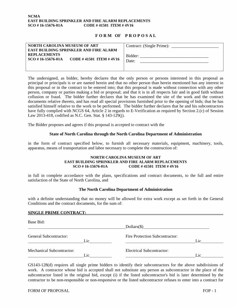
NCMA EAST BUILDING SPRINKLER AND FIRE ALARM REPLACEMENTS SCO # 16-15676-01A CODE # 41501 ITEM # 4V16
FORM OF PROPOSAL FOP - 1
F O R M OF P R O P O S A L
NORTH CAROLINA MUSEUM OF ART EAST BUILDING SPRINKLER AND FIRE ALARM REPLACEMENTS SCO # 16-15676-01A CODE # 41501 ITEM # 4V16
Contract: (Single Prime): ______________________ Bidder: ________________________________ Date: ________________________________
The undersigned, as bidder, hereby declares that the only person or persons interested in this proposal as principal or principals is or are named herein and that no other person than herein mentioned has any interest in this proposal or in the contract to be entered into; that this proposal is made without connection with any other person, company or parties making a bid or proposal; and that it is in all respects fair and in good faith without collusion or fraud. The bidder further declares that he has examined the site of the work and the contract documents relative thereto, and has read all special provisions furnished prior to the opening of bids; that he has satisfied himself relative to the work to be performed. The bidder further declares that he and his subcontractors have fully complied with NCGS 64, Article 2 in regards to E-Verification as required by Section 2.(c) of Session Law 2013-418, codified as N.C. Gen. Stat. § 143-129(j). The Bidder proposes and agrees if this proposal is accepted to contract with the
State of North Carolina through the North Carolina Department of Administration in the form of contract specified below, to furnish all necessary materials, equipment, machinery, tools, apparatus, means of transportation and labor necessary to complete the construction of:
NORTH CAROLINA MUSEUM OF ART
EAST BUILDING SPRINKLER AND FIRE ALARM REPLACEMENTS SCO # 16-15676-01A CODE # 41501 ITEM # 4V16
in full in complete accordance with the plans, specifications and contract documents, to the full and entire satisfaction of the State of North Carolina, and
The North Carolina Department of Administration with a definite understanding that no money will be allowed for extra work except as set forth in the General Conditions and the contract documents, for the sum of: SINGLE PRIME CONTRACT: Base Bid: Dollars($) General Subcontractor: Fire Protection Subcontractor: Lic Lic Mechanical Subcontractor: Electrical Subcontractor: Lic Lic GS143-128(d) requires all single prime bidders to identify their subcontractors for the above subdivisions of work. A contractor whose bid is accepted shall not substitute any person as subcontractor in the place of the subcontractor listed in the original bid, except (i) if the listed subcontractor's bid is later determined by the contractor to be non-responsible or non-responsive or the listed subcontractor refuses to enter into a contract for

NCMA EAST BUILDING SPRINKLER AND FIRE ALARM REPLACEMENTS SCO # 16-15676-01A CODE # 41501 ITEM # 4V16
FORM OF PROPOSAL FOP - 2
the complete performance of the bid work, or (ii) with the approval of the awarding authority for good cause shown by the contractor. ALTERNATES: Should any of the alternates as described in the contract documents be accepted, the amount written below shall be the amount to be "added to" or "deducted from" the base bid. (Strike out "Add" or "Deduct" as appropriate.) Alternate No. 1A: Shall include all sprinkler work on the “C” Level (Add) Dollars ($) Alternate No. 1B: Shall include all sprinkler work on the “Tunnel” Level (Add) Dollars ($) Alternate No. 2: Shall include all sprinkler work in Gallery #1 of the “B” Level (Add) Dollars ($) UNIT PRICES Unit prices quoted and accepted shall apply throughout the life of the contract, except as otherwise specifically noted. Unit prices shall be applied, as appropriate, to compute the total value of changes in the base bid quantity of the work all in accordance with the contract documents. No. E1 Smoke Detector Each Unit Price ($) No. E2 Pull Station Each Unit Price ($) No. E3 Speaker/Strobe Each Unit Price ($) No. F1 Sprinkler Head Each Unit Price ($) No. F2 Sprinkler Head Each Unit Price ($) No. F3 Sprinkler Head Each Unit Price ($) The bidder further proposes and agrees hereby to commence work under this contract on a date to be specified in a written order of the designer and shall fully complete all work thereunder within the time specified in the Supplementary General Conditions Article 23. Applicable liquidated damages amount is also stated in the Supplementary General Conditions Article 23. MINORITY BUSINESS PARTICIPATION REQUIREMENTS; Provide with the bid - Under GS 143-128.2(c) the undersigned bidder shall identify on its bid (Identification of Minority Business Participation Form) the minority businesses that it will use on the project with the total dollar value of the bids that will be performed by the minority businesses. Also list the good faith efforts (Affidavit A) made to solicit minority participation in the bid effort.

NCMA EAST BUILDING SPRINKLER AND FIRE ALARM REPLACEMENTS SCO # 16-15676-01A CODE # 41501 ITEM # 4V16
FORM OF PROPOSAL FOP - 3
NOTE: A contractor that performs all of the work with its own workforce may submit an Affidavit (B) to that effect in lieu of Affidavit (A) required above. The MB Participation Form must still be submitted even if there is zero participation.
After the bid opening - The Owner will consider all bids and alternates and determine the lowest responsible, responsive bidder. Upon notification of being the apparent low bidder, the bidder shall then file within 72 hours of the notification of being the apparent lowest bidder, the following:
An Affidavit (C) that includes a description of the portion of work to be executed by minority businesses, expressed as a percentage of the total contract price, which is equal to or more than the 10% goal established. This affidavit shall give rise to the presumption that the bidder has made the required good faith effort and Affidavit D is not necessary; OR If less than the 10% goal, Affidavit (D) of its good faith effort to meet the goal shall be provided. The document must include evidence of all good faith efforts that were implemented, including any advertisements, solicitations and other specific actions demonstrating recruitment and selection of minority businesses for participation in the contract.
Note: Bidders must always submit with their bid the Identification of Minority Business Participation Form listing all MB contractors, vendors and suppliers that will be used. If there is no MB participation, then enter none or zero on the form. Affidavit A or Affidavit B, as applicable, also must be submitted with the bid. Failure to file a required affidavit or documentation with the bid or after being notified apparent low bidder is grounds for rejection of the bid.

NCMA EAST BUILDING SPRINKLER AND FIRE ALARM REPLACEMENTS SCO # 16-15676-01A CODE # 41501 ITEM # 4V16
FORM OF PROPOSAL FOP - 4
Proposal Signature Page The undersigned further agrees that in the case of failure on his part to execute the said contract and the bonds within ten (10) consecutive calendar days after being given written notice of the award of contract, the certified check, cash or bid bond accompanying this bid shall be paid into the funds of the owner's account set aside for the project, as liquidated damages for such failure; otherwise the certified check, cash or bid bond accompanying this proposal shall be returned to the undersigned. Respectfully submitted this day of
(Name of firm or corporation making bid) WITNESS: By: Signature Name: (Proprietorship or Partnership) Print or type Title______________ (Owner/Partner/Pres./V.Pres) Address _ ATTEST: By: License No. Title: Federal I.D. No.
(Corp. Sec. or Asst. Sec. only)
(CORPORATE SEAL) Addendum received and used in computing bid: Addendum No. 1 Addendum No. 3 Addendum No. 5 Addendum No. 6 Addendum No. 2 Addendum No. 4 Addendum No. 6 Addendum No. 7
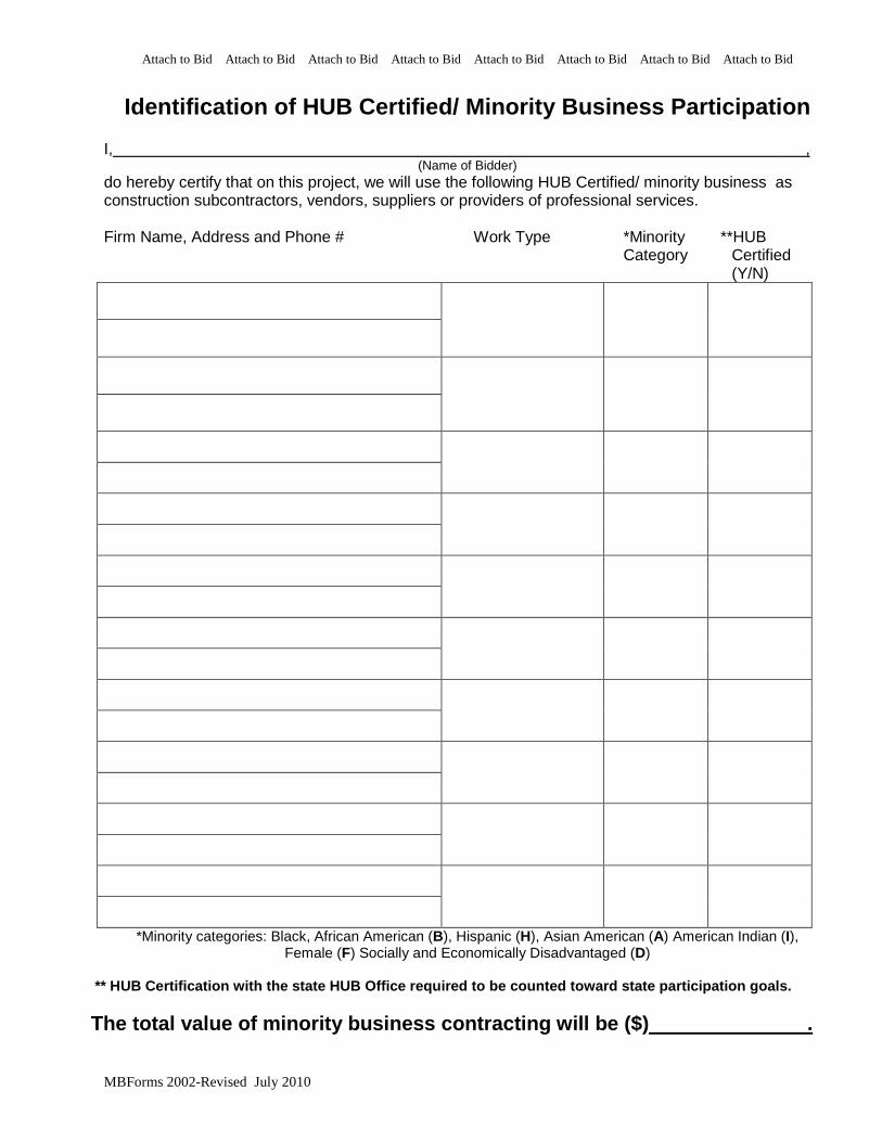
Attach to Bid Attach to Bid Attach to Bid Attach to Bid Attach to Bid Attach to Bid Attach to Bid Attach to Bid
MBForms 2002-Revised July 2010
Identification of HUB Certified/ Minority Business Participation
I, ,
(Name of Bidder) do hereby certify that on this project, we will use the following HUB Certified/ minority business as construction subcontractors, vendors, suppliers or providers of professional services. Firm Name, Address and Phone # Work Type *Minority **HUB
Category Certified (Y/N)
*Minority categories: Black, African American (B), Hispanic (H), Asian American (A) American Indian (I), Female (F) Socially and Economically Disadvantaged (D)
** HUB Certification with the state HUB Office required to be counted toward state participation goals.
The total value of minority business contracting will be ($) .

Attach to Bid Attach to Bid Attach to Bid Attach to Bid Attach to Bid Attach to Bid Attach to Bid Attach to Bid
MBForms 2002-Revised July 2010
State of North Carolina AFFIDAVIT A – Listing of Good Faith Efforts County of
(Name of Bidder) Affidavit of
I have made a good faith effort to comply under the following areas checked: Bidders must earn at least 50 points from the good faith efforts listed for their bid to be considered responsive. (1 NC Administrative Code 30 I.0101) 1 – (10 pts) Contacted minority businesses that reasonably could have been expected to submit a quote and
that were known to the contractor, or available on State or local government maintained lists, at least 10 days before the bid date and notified them of the nature and scope of the work to be performed.
2 --(10 pts) Made the construction plans, specifications and requirements available for review by prospective minority businesses, or providing these documents to them at least 10 days before the bids are due.
3 – (15 pts) Broken down or combined elements of work into economically feasible units to facilitate minority participation.
4 – (10 pts) Worked with minority trade, community, or contractor organizations identified by the Office of Historically Underutilized Businesses and included in the bid documents that provide assistance in recruitment of minority businesses.
5 – (10 pts) Attended prebid meetings scheduled by the public owner. 6 – (20 pts) Provided assistance in getting required bonding or insurance or provided alternatives to bonding
or insurance for subcontractors. 7 – (15 pts) Negotiated in good faith with interested minority businesses and did not reject them as
unqualified without sound reasons based on their capabilities. Any rejection of a minority business based on lack of qualification should have the reasons documented in writing.
8 – (25 pts) Provided assistance to an otherwise qualified minority business in need of equipment, loan capital, lines of credit, or joint pay agreements to secure loans, supplies, or letters of credit, including waiving credit that is ordinarily required. Assisted minority businesses in obtaining the same unit pricing with the bidder's suppliers in order to help minority businesses in establishing credit.
9 – (20 pts) Negotiated joint venture and partnership arrangements with minority businesses in order to increase opportunities for minority business participation on a public construction or repair project when possible.
10 - (20 pts) Provided quick pay agreements and policies to enable minority contractors and suppliers to meet cash-flow demands.
The undersigned, if apparent low bidder, will enter into a formal agreement with the firms listed in the Identification of Minority Business Participation schedule conditional upon scope of contract to be executed with the Owner. Substitution of contractors must be in accordance with GS143-128.2(d) Failure to abide by this statutory provision will constitute a breach of the contract. The undersigned hereby certifies that he or she has read the terms of the minority business commitment and is authorized to bind the bidder to the commitment herein set forth.
Date: Name of Authorized Officer: Signature: Title:
State of______________, County of Subscribed and sworn to before me this day of 20 Notary Public My commission expires
SEAL

Attach to Bid Attach to Bid Attach to Bid Attach to Bid Attach to Bid Attach to Bid Attach to Bid Attach to Bid
MBForms 2002-Revised July 2010
State of North Carolina --AFFIDAVIT B-- Intent to Perform Contract with Own Workforce. County of Affidavit of
(Name of Bidder) I hereby certify that it is our intent to perform 100% of the work required for the contract.
(Name of Project) In making this certification, the Bidder states that the Bidder does not customarily subcontract elements of this type project, and normally performs and has the capability to perform and will perform all elements of the work on this project with his/her own current work forces; and
The Bidder agrees to provide any additional information or documentation requested by the owner in support of the above statement. The Bidder agrees to make a Good Faith Effort to utilize minority suppliers where possible. The undersigned hereby certifies that he or she has read this certification and is authorized to bind the Bidder to the commitments herein contained. Date: Name of Authorized Officer: Signature: Title: State of _________ __ , County of ________________________ Subscribed and sworn to before me this day of 20___ Notary Public My commission expires
SEAL
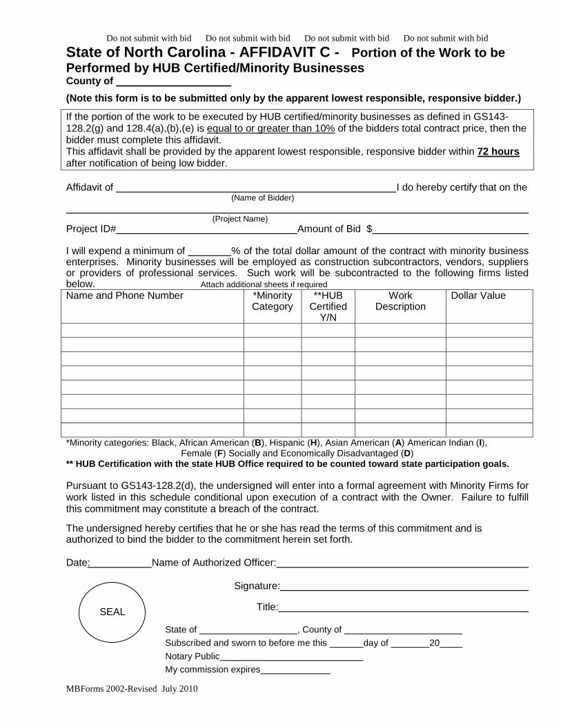
Do not submit with bid Do not submit with bid Do not submit with bid Do not submit with bid
MBForms 2002-Revised July 2010
State of North Carolina - AFFIDAVIT C - Portion of the Work to be Performed by HUB Certified/Minority Businesses County of
(Note this form is to be submitted only by the apparent lowest responsible, responsive bidder.)
If the portion of the work to be executed by HUB certified/minority businesses as defined in GS143-128.2(g) and 128.4(a),(b),(e) is equal to or greater than 10% of the bidders total contract price, then the bidder must complete this affidavit. This affidavit shall be provided by the apparent lowest responsible, responsive bidder within 72 hours after notification of being low bidder. Affidavit of I do hereby certify that on the (Name of Bidder)
(Project Name) Project ID# Amount of Bid $ I will expend a minimum of % of the total dollar amount of the contract with minority business enterprises. Minority businesses will be employed as construction subcontractors, vendors, suppliers or providers of professional services. Such work will be subcontracted to the following firms listed below. Attach additional sheets if required Name and Phone Number *Minority
Category **HUB
Certified Y/N
Work Description
Dollar Value
*Minority categories: Black, African American (B), Hispanic (H), Asian American (A) American Indian (I),
Female (F) Socially and Economically Disadvantaged (D) ** HUB Certification with the state HUB Office required to be counted toward state participation goals.
Pursuant to GS143-128.2(d), the undersigned will enter into a formal agreement with Minority Firms for work listed in this schedule conditional upon execution of a contract with the Owner. Failure to fulfill this commitment may constitute a breach of the contract. The undersigned hereby certifies that he or she has read the terms of this commitment and is authorized to bind the bidder to the commitment herein set forth. Date: Name of Authorized Officer: Signature: Title:
State of , County of Subscribed and sworn to before me this day of 20 Notary Public My commission expires
SEAL

Do not submit with the bid Do not submit with the bid Do not submit with the bid Do not submit with the bid Do not submit with the bid
MBForms 2002-Revised May 2010 -1-
State of North Carolina AFFIDAVIT D – Good Faith Efforts County of (Note this form is to be submitted only by the apparent lowest responsible, responsive bidder.) If the goal of 10% participation by HUB Certified/ minority business is not achieved, the Bidder shall provide the following documentation to the Owner of his good faith efforts: Affidavit of I do hereby certify that on the (Name of Bidder)
(Project Name) Project ID# Amount of Bid $ I will expend a minimum of % of the total dollar amount of the contract with HUB certified/ minority business enterprises. Minority businesses will be employed as construction subcontractors, vendors, suppliers or providers of professional services. Such work will be subcontracted to the following firms listed below. (Attach additional sheets if required) Name and Phone Number *Minority
Category **HUB
Certified Y/N
Work Description
Dollar Value
*Minority categories: Black, African American (B), Hispanic (H), Asian American (A) American Indian (I),
Female (F) Socially and Economically Disadvantaged (D) ** HUB Certification with the state HUB Office required to be counted toward state participation goals.
Examples of documentation that may be required to demonstrate the Bidder's good faith efforts to meet the goals set forth in these provisions
include, but are not necessarily limited to, the following: A. Copies of solicitations for quotes to at least three (3) minority business firms from the source list provided by the State for each subcontract
to be let under this contract (if 3 or more firms are shown on the source list). Each solicitation shall contain a specific description of the work to be subcontracted, location where bid documents can be reviewed, representative of the Prime Bidder to contact, and location, date and time when quotes must be received.
B. Copies of quotes or responses received from each firm responding to the solicitation.
C. A telephone log of follow-up calls to each firm sent a solicitation. D. For subcontracts where a minority business firm is not considered the lowest responsible sub-bidder, copies of quotes received from all
firms submitting quotes for that particular subcontract. E. Documentation of any contacts or correspondence to minority business, community, or contractor organizations in an attempt to meet the goal.
F. Copy of pre-bid roster
G. Letter documenting efforts to provide assistance in obtaining required bonding or insurance for minority business.
H. Letter detailing reasons for rejection of minority business due to lack of qualification.
I. Letter documenting proposed assistance offered to minority business in need of equipment, loan capital, lines of credit, or joint pay
agreements to secure loans, supplies, or letter of credit, including waiving credit that is ordinarily required.
Failure to provide the documentation as listed in these provisions may result in rejection of the bid and award to the next lowest responsible and responsive bidder.
Pursuant to GS143-128.2(d), the undersigned will enter into a formal agreement with Minority Firms for work listed in this schedule conditional upon execution of a contract with the Owner. Failure to fulfill this commitment may constitute a breach of the contract.

Do not submit with the bid Do not submit with the bid Do not submit with the bid Do not submit with the bid Do not submit with the bid
MBForms 2002-Revised May 2010 -2-
The undersigned hereby certifies that he or she has read the terms of this commitment and is authorized to bind the bidder to the commitment herein set forth. Date: Name of Authorized Officer:
Signature:
Title: State of , County of Subscribed and sworn to before me this day of 20 Notary Public My commission expires
SEAL

FORM OF BID BOND
KNOW ALL MEN BY THESE PRESENTS THAT ________________ __________________________________________________________________ as principal, and _______________________________________________, as surety, who is duly licensed to act as surety in North Carolina, are held and firmly bound unto the State of North Carolina* through _______________________________________________ as obligee, in the penal sum of ___________________________ DOLLARS, lawful money of the United States of America, for the payment of which, well and truly to be made, we bind ourselves, our heirs, executors, administrators, successors and assigns, jointly and severally, firmly by these presents. Signed, sealed and dated this day of 20 WHEREAS, the said principal is herewith submitting proposal for and the principal desires to file this bid bond in lieu of making the cash deposit as required by G.S. 143-129. NOW, THEREFORE, THE CONDITION OF THE ABOVE OBLIGATION is such, that if the principal shall be awarded the contract for which the bid is submitted and shall execute the contract and give bond for the faithful performance thereof within ten days after the award of same to the principal, then this obligation shall be null and void; but if the principal fails to so execute such contract and give performance bond as required by G.S. 143-129, the surety shall, upon demand, forthwith pay to the obligee the amount set forth in the first paragraph hereof. Provided further, that the bid may be withdrawn as provided by G.S. 143-129.1 (SEAL) (SEAL) (SEAL) (SEAL) (SEAL) *(Community college projects: Delete State of North Carolina as owner and replace with community college name.)


FORM OF CONSTRUCTION CONTRACT THIS AGREEMENT, made the ____________ day of _____________ in
the year of 20__ by and between _______________________________ __________________________________________________________________
hereinafter called the Party of the First Part and the State of North Carolina through North
Carolina Department of Administration hereinafter called the Party of the Second Part. WITNESSETH: That the Party of the First Part and the Party of the Second Part for the consideration herein named agree as follows: 1. Scope of Work: The Party of the First Part shall furnish and deliver all of the
materials, and perform all of the work in the manner and form as provided by the following enumerated plans, specifications and documents, which are attached hereto and made a part thereof as if fully contained herein: advertisement; Instructions to Bidders; General Conditions; Supplementary General Conditions; specifications; accepted proposal; contract; performance bond; payment bond; power of attorney; workmen's compensation; public liability; property damage and builder's risk insurance certificates; approval of attorney general; certificate by the Office of State Budget and Management, and drawings, titled:
________________________________________________________________ Consisting of the following sheets:
________________________________________________________________ Dated: and the following addenda: Addendum No Dated: Addendum No. Dated: Addendum No Dated: Addendum No. Dated: Addendum No Dated: Addendum No. Dated: Addendum No Dated: Addendum No. Dated: 2. That the Party of the First Part shall commence work to be performed under this agreement on a date to be specified in a written order of the Party of the Second Part and shall fully complete all work hereunder within _____________ consecutive calendar days from said date. For each day in excess thereof, liquidated damages shall be as stated in Supplementary General Conditions. The Party of the First Part, as one of the considerations for the awarding of this contract, shall furnish to the Party of the Second Part a construction schedule setting forth planned progress of the project broken down by the various divisions or part of the work and by calendar days. If the Party of the First Part fails to begin the work under the contract within the time specified, or the progress of the work is not maintained on schedule, or the work is not completed within the time above

specified, or fails to perform the work with sufficient workmen and equipment or with sufficient materials to ensure the prompt completion of said work, or shall perform the work unsuitably or shall discontinue the prosecution of the work, or if the Party of the First Part shall become insolvent or be declared bankrupt or commit any act of bankruptcy or insolvency, or allow any final judgment to stand against him unsatisfied for a period of forty-eight (48) hours, or shall make an assignment for the benefit of creditors, or for any other cause whatsoever shall not carry on the work in an acceptable manner, the Party of the Second Part may give notice in writing, sent by certified mail, return receipt requested, to the Party of the First Part and his surety of such delay, neglect or default, specifying the same, and if the Party of the First Part within a period of fifteen (15) days after such notice shall not proceed in accordance therewith, then the Party of the Second Part shall, declare this contract in default, and, thereupon, the surety shall promptly take over the work and complete the performance of this contract in the manner and within the time frame specified. In the event the surety shall fail to take over the work to be done under this contract within fifteen (15) days after being so notified and notify the Party of the Second Part in writing, sent by certified mail, return receipt requested, that he is taking the same over and stating that he will diligently pursue and complete the same, the Party of the Second Part shall have full power and authority, without violating the contract, to take the prosecution of the work out of the hands of said Party of the First Part, to appropriate or use any or all contract materials and equipment on the grounds as may be suitable and acceptable and may enter into an agreement, either by public letting or negotiation, for the completion of said contract according to the terms and provisions thereof or use such other methods as in his opinion shall be required for the completion of said contract in an acceptable manner. All costs and charges incurred by the Party of the Second Part, together with the costs of completing the work under contract, shall be deducted from any monies due or which may become due said Party of the First Part and surety. In case the expense so incurred by the Party of the Second Part shall be less than the sum which would have been payable under the contract, if it had been completed by said Party of the First Part, then the said Party of the First Part and surety shall be entitled to receive the difference, but in case such expense shall exceed the sum which would have been payable under the contract, then the Party of the First Part and the surety shall be liable and shall pay to the Party of the Second Part the amount of said excess. 3. The Party of the Second Part hereby agrees to pay to the Party of the First Part for the faithful performance of this agreement, subject to additions and deductions as provided in the specifications or proposal, in lawful money of the United States as follows: _______________________________________ ____________ ________________________________________ ($ __________________). Summary of Contract Award: 4. On or before the 20th day of each calendar month, the Party of the Second Part shall make payments to the Party of the First Part on the basis of a duly certified and approved estimate of work performed during the preceding calendar month by the First Party, less five percent (5%) of the amount of such estimate which is to be retained by the Second Party until all work has been performed strictly in accordance with this agreement and until such work has been accepted by the Second Party. The Second Party may elect to waive retainage requirements after 50 percent of the work has been satisfactorily completed on schedule as referred to in Article 31 of the General Conditions. 5. Upon submission by the First Party of evidence satisfactory to the Second Party that all payrolls, material bills and other costs incurred by the First Party in connection with

the construction of the work have been paid in full, final payment on account of this agreement shall be made within thirty (30) days after the completion by the First Party of all work covered by this agreement and the acceptance of such work by the Second Party. 6. It is further mutually agreed between the parties hereto that if at any time after the execution of this agreement and the surety bonds hereto attached for its faithful performance, the Second Party shall deem the surety or sureties upon such bonds to be unsatisfactory, or if, for any reason, such bonds cease to be adequate to cover the performance of the work, the First Party shall, at its expense, within five (5) days after the receipt of notice from the Second Party so to do, furnish an additional bond or bonds in such form and amount, and with such surety or sureties as shall be satisfactory to the Second Party. In such event no further payment to the First Party shall be deemed to be due under this agreement until such new or additional security for the faithful performance of the work shall be furnished in manner and form satisfactory to the Second Party. IN WITNESS WHEREOF, the Parties hereto have executed this agreement on the day and date first above written in ____________ counterparts, each of which shall without proof or accounting for other counterparts, be deemed an original contract. Witness:
Contractor: (Trade or Corporate Name) ____________________________ By: _______________________________ (Proprietorship or Partnership) Title: (Owner, Partner, or Corp. Pres. or Vice Pres. only) Attest: (Corporation) By: Title: (Corp. Sec. or Asst. Sec. only) The State of North Carolina through
North Carolina Department of Administration (CORPORATE SEAL) (Agency, Department or Institution) Witness: By: Title:


FORM OF PERFORMANCE BOND Date of Contract:
Date of Execution:
Name of Principal (Contractor)
Name of Surety:
Name of Contracting Body:
Amount of Bond:
Project
KNOW ALL MEN BY THESE PRESENTS, that we, the principal and surety above named, are held and firmly bound unto the above named contracting body, hereinafter called the contracting body, in the penal sum of the amount stated above for the payment of which sum well and truly to be made, we bind, ourselves, our heirs, executors, administrators, and successors, jointly and severally, firmly by these presents. THE CONDITION OF THIS OBLIGATION IS SUCH, that whereas the principal entered into a certain contract with the contracting body, identified as shown above and hereto attached: NOW, THEREFORE, if the principal shall well and truly perform and fulfill all the undertakings, covenants, terms, conditions and agreements of said contract during the original term of said contract and any extensions thereof that may be granted by the contracting body, with or without notice to the surety, and during the life of any guaranty required under the contract, and shall also well and truly perform and fulfill all the undertakings, covenants, terms, conditions and agreements of any and all duly authorized modifications of said contract that may hereafter be made, notice of which modifications to the surety being hereby waived, then, this obligation to be void; otherwise to remain in full force and virtue. IN WITNESS WHEREOF, the above-bounden parties have executed this instrument under their several seals on the date indicated above, the name and corporate seal of each corporate party being hereto affixed and these presents duly signed by its undersigned representative, pursuant to authority of its governing body. Executed in counterparts.

Witness: Contractor: (Trade or Corporate Name) By: (Proprietorship or Partnership) Attest: (Corporation) Title: (Owner, Partner, or Corp. Pres. or Vice
Pres. only) By: Title: (Corp. Sec. or Asst. Sec.. only) (Corporate Seal) (Surety Company) Witness: By: Title: (Attorney in Fact) Countersigned: (Surety Corporate Seal) (N.C. Licensed Resident Agent) Name and Address-Surety Agency Surety Company Name and N.C. Regional or Branch Office Address

FORM OF PAYMENT BOND
Date of Contract:
Date of Execution:
Name of Principal (Contractor)
Name of Surety:
Name of Contracting Body:
Amount of Bond:
Project
KNOW ALL MEN BY THESE PRESENTS, that we, the principal and surety above named, are held and firmly bound unto the above named contracting body, hereinafter called the contracting body, in the penal sum of the amount stated above for the payment of which sum well and truly to be made, we bind ourselves, our heirs, executors, administrators, and successors, jointly and severally, firmly by these presents. THE CONDITION OF THIS OBLIGATION IS SUCH, that whereas the principal entered into a certain contract with the contracting body identified as shown above and hereto attached: NOW, THEREFORE, if the principal shall promptly make payment to all persons supplying labor/material in the prosecution of the work provided for in said contract, and any and all duly authorized modifications of said contract that may hereafter be made, notice of which modifications to the surety being hereby waived, then this obligation to be void; otherwise to remain in full force and virtue. IN WITNESS WHEREOF, the above-bounden parties have executed this instrument under their several seals on the date indicated above, the name and corporate seal of each corporate party being hereto affixed and these presents duly signed by its undersigned representative, pursuant to authority of its governing body. Executed in counterparts.
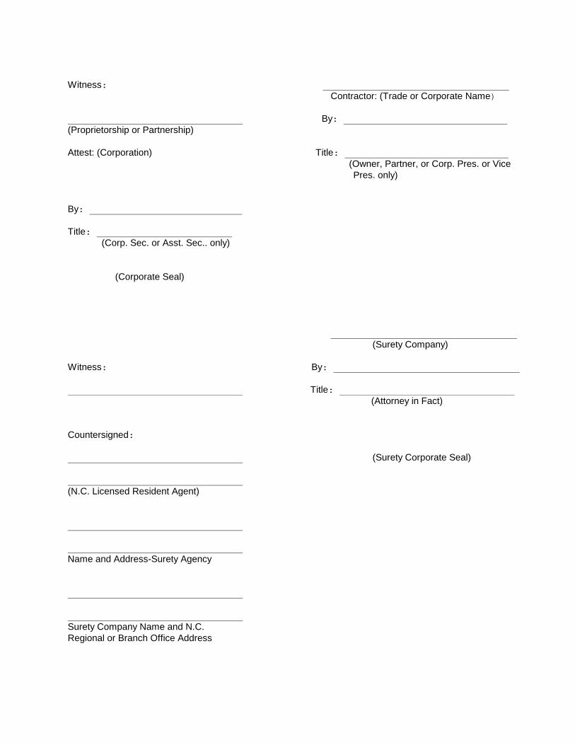
Witness: Contractor: (Trade or Corporate Name) By: (Proprietorship or Partnership) Attest: (Corporation) Title: (Owner, Partner, or Corp. Pres. or Vice
Pres. only) By: Title: (Corp. Sec. or Asst. Sec.. only) (Corporate Seal) (Surety Company) Witness: By: Title: (Attorney in Fact) Countersigned: (Surety Corporate Seal) (N.C. Licensed Resident Agent) Name and Address-Surety Agency Surety Company Name and N.C. Regional or Branch Office Address

Sheet for Attaching Power of Attorney

Sheet for Attaching Insurance Certificates

APPROVAL OF THE ATTORNEY GENERAL

CERTIFICATION BY THE OFFICE OF STATE BUDGET AND MANAGEMENT
Provision for the payment of money to fall due and payable by the under this agreement has been provided for by allocation made and is available for the purpose of carrying out this agreement. This _____________day of _________ __________ 20___. Signed Budget Officer