ncp4353 - secondary side smps off mode controller for low
TRANSCRIPT

© Semiconductor Components Industries, LLC, 2015
April, 2015 − Rev. 41 Publication Order Number:
NCP4353/D
NCP4353, NCP4354
Secondary Side SMPS OFFMode Controller for LowStandby Power
The NCP4353/4 is a secondary side SMPS controller designed foruse in applications which require extremely low no load powerconsumption. The device is capable of detecting “no load” conditionsand entering the power supply into a low consumption OFF mode.During OFF mode, the primary side controller is turned off and energyis provided by the output capacitors thus eliminating the powerconsumption required to maintain regulation. During OFF mode, theoutput voltage relaxes and is allowed to decrease to an adjustablelevel. Once more energy is required, the NCP4353/4 automaticallyrestarts the primary side controller. The NCP4353/4 controls theprimary side controller with an “Active OFF” signal, meaning that itdrives optocoupler current during OFF mode to pull−down the FB pinof the primary controller.
During normal power supply operation, the NCP4353/4 providesintegrated voltage feedback regulation, replacing the need for a shuntregulator. The A versions include a current regulation loop in additionto voltage regulation. Feedback control as well as ON/OFF signal canbe provided with only one optocoupler.
The NCP4354 includes a LED driver pin implemented with an opendrain MOSFET driven by a 1 kHz square wave with a 12.5% dutycycle when primary side is in regulation for indication purpose.
The NCP4353 is available in TSOP−6 package while the NCP4354is available in SOIC−8 package.
Features• Operating Input Voltage Range: 2.5 V to 36.0 V
• Supply Current < 100 �A
• ±0.5% Reference Voltage Accuracy (TJ = 25°C)
• Constant Voltage and Constant Current (A versions) Control Loop
• Indication LED PWM Modulated Driver (NCP4354x)
• Designed for use with NCP1246 Fixed Frequency PWM Controller
• These Devices are Pb−Free, Halogen Free/BFR Free and are RoHSCompliant
Typical Applications• Offline Adapters for Notebooks, Game Stations and Printers
• High Power AC−DC Converters for TVs, Set−Top Boxes, Monitors, etc.
DEVICE OPTIONS
NCP4353A NCP4353B NCP4354A NCP4354B
AdjustableVmin
No Yes Yes Yes
CurrentRegulation
Yes No Yes No
LED Driver No No Yes Yes
Package TSOP−6 TSOP−6 SOIC−8 SOIC−8
www.onsemi.com
MARKINGDIAGRAMS
SOIC−8CASE 751
1
8XXXXXALYW �
�1
8
1
XXXAYW�
�
1
TSSOP−6CASE 318G
A = Assembly LocationL = Wafer LotY = YearW = Work Week� = Pb−Free Package
See detailed ordering, marking and shipping information in thepackage dimensions section on page 15 of this data sheet.
ORDERING INFORMATION
(Note: Microdot may be in either location)

NCP4353, NCP4354
www.onsemi.com2
SW1
VREF
VCC
managementPowerRESET
VDD
VoltageRegulation
Off ModeDetection
IDRIVEOFF
SW3
IBIASV
VREFC
CurrentRegulation
OTA
VDD
PowerRESET
OTA
Sink only
Sink only
VREF
IBIASV
Enabling
0.9 x VREF
Power RESET
S
R
Q
Q
NCP4353A
SW1
VREF
VREFM
VCC
managementPowerRESET
VDD
VoltageRegulation
Off ModeDetection
IDRIVEOFF
SW3
IBIASV
VDD
PowerRESET
OTA
VCC
VSNS
GND
OFFDET
Min OutputVoltage
DRIVESink only
VMIN
VREF
IBIASV
Enabling
0.9 x VREF
VCC
Power RESET
S
R
Q
Q
10%VCC
NCP4353B
Figure 1. Simplified Block Diagrams NCP4353A and NCP4353B
VCC
DRIVE
GND
ISNS
VSNS
OFFDET
10%VCC
VCC

NCP4353, NCP4354
www.onsemi.com3
SW1
VREF
VREFM
VCC
managementPowerRESET
VDD
VoltageRegulation
Off ModeDetection
1 kHz, 12% D.C.Oscillator
IDRIVEOFF
SW3
IBIASV
VREFC
CurrentRegulation
OTA
VDD
PowerRESET
OTA
VCC ISNS
SW2
LED
VSNS
GND
OFFDET
Min OutputVoltage
DRIVE
Sink only
Sink only
VMIN
VREF
IBIASV
Enabling
0.9 x VREF
VCC
Power RESET
S
R
Q
Q
10%VCC
NCP4354A
SW1
VREF
VREFM
VCC
managementPowerRESET
VDD
VoltageRegulation
Off ModeDetection
1 kHz, 12% D.C.Oscillator
IDRIVEOFF
SW3
IBIASV
VDD
PowerRESET
OTA
VCC
SW2
LED
VSNS
GND
OFFDET
Min OutputVoltage
FBCSink only
VMIN
VREF
IBIASV
Enabling
0.9 x VREF
VCC
Power RESET
S
R
Q
Q
10%VCC
ON/OFF
NCP4354B
Figure 2. Simplified Block Diagrams NCP4354A and NCP4354B

NCP4353, NCP4354
www.onsemi.com4
PIN FUNCTION DESCRIPTION
NCP4353A NCP4353B NCP4354A NCP4354B Pin Name Description
1 1 8 8 VCC Supply voltage pin
2 2 7 7 GND Ground
6 6 1 1 VSNS Output voltage sensing pin, connected to outputvoltage divider
5 5 2 2 OFFDET OFF mode detection input. Voltage divider pro-vides adjustable off mode detection threshold
− 4 3 3 VMIN Minimum output voltage adjustment
4 − 4 − ISNS Current sensing input for output current regulation,connect it to shunt resistor in ground branch.
− − 5 4 LED PWM LED driver output. Connected to LED cath-ode with current define by external serial resist-ance
− − − 6 FBC Output of current sinking OTA amplifier or amplifi-ers driving feedback optocoupler’s LED. Connecthere compensation network (networks) as well.
− − − 5 ON/OFF OFF mode current sink. This output keeps primarycontrol pin at low level in off mode.
3 3 6 − DRIVE Combination of FBC and ON/OFF pins
ABSOLUTE MAXIMUM RATINGS
Rating Symbol Value Unit
Input Voltage VCC −0.3 to 40 V
DRIVE, ON/OFF, FBC, LED Voltage VDRIVE, VONOFF,VFBC, VLED
−0.3 to VCC + 0.3 V
VSNS, ISNS, OFFDET, VMIN Voltage VSNS, VISNS,VOFFDET, VMIN
−0.3 to 10 V
LED Current ILED 10 mA
Thermal Resistance − Junction−to−Air (Note 1) NCP4353ANCP4353BNCP4354ANCP4354B
R�JA 315324260277
°C/W
Junction Temperature TJ −40 to 150 °C
Storage Temperature TSTG −60 to 150 °C
ESD Capability, Human Body Model (Note 2) ESDHBM 2000 V
ESD Capability, Machine Model (Note 2) ESDMM 250 V
ESD Capability, Charged Device Model (Note 2) ESDCDM 1000 V
Stresses exceeding those listed in the Maximum Ratings table may damage the device. If any of these limits are exceeded, device functionalityshould not be assumed, damage may occur and reliability may be affected.1. 50 mm2, 1.0 oz. Copper spreader.2. This device series incorporates ESD protection and is tested by the following methods:
ESD Human Body Model tested per JESD22−A114FESD Machine Model tested per JESD22−A115CESD Charged Device Model tested per JESD22−C101FLatchup Current Maximum Rating tested per JEDEC standard: JESD78D.

NCP4353, NCP4354
www.onsemi.com5
ELECTRICAL CHARACTERISTICS0°C ≤ TJ ≤ 125°C; VCC = 15 V; unless otherwise noted. Typical values are at TJ = +25°C.
Parameter Test Conditions Symbol Min Typ Max Unit
Maximum Operating Input Volt-age
VCC 36.0 V
VCC UVLO VCC rising VCCUVLO 3.3 3.5 3.7 V
VCC falling 2.3 2.5 2.7
VCC UVLO Hysteresis VCCUVLOHYS 0.8 1.0 V
Quiescent Current in Regulation
NCP4353A ICC 101 125 �A
NCP4353B 82 105
NCP4354A 118 145
NCP4354B 95 120
Quiescent Current in OFF Mode VSNS < 1.12 V ICC,OFFmode 90 110 �A
VOLTAGE CONTROL LOOP OTA
Transconductance Sink current only gmV 1 S
Reference Voltage 2.8 V ≤ VCC ≤ 36.0 V, TJ = 25°C VREF 1.244 1.250 1.256 V
2.8 V ≤ VCC ≤ 36.0 V, TJ = 0 − 85°C 1.240 1.250 1.264
2.8 V ≤ VCC ≤ 36.0 V, TJ = 0 − 125°C 1.230 1.250 1.270
Sink Current Capability In regulation, VDRIVE or VFBC > 1.5 V ISINKV 2.5 mA
In OFF mode, VDRIVE or VFBC > 1.5 V 1.2 1.5 2.0 mA
Inverting Input Bias Current In regulation, VSNS = VREF IBIASV −100 100 nA
In OFF mode, VSNS > 1.12 V −13 −11 −10 �A
Inverting Input Bias CurrentThreshold
In OFF mode VSNSBIASTH 1.07 1.12 1.17 V
CURRENT CONTROL LOOP OTA (NCP435xA only)
Transconductance Sink current only gmC 3 S
Reference Voltage VREFC 60 62.5 65 mV
Sink Current Capability VDRIVE or VFBC > 1.5 V ISINKC 2.5 mA
Inverting Input Bias Current ISNS = VREFC IBIASC −100 100 nA
MINIMUM VOLTAGE COMPARATOR (except NCP4353A)
Threshold Voltage VREFM 355 377 400 mV
Hysteresis Output change from logic high to logic low VMINH 40 mV
OFF MODE DETECTION COMPARATOR
Threshold Value 2.5 V ≤ VCC ≤ 36.0 V VOFFDETTH 10% VCC V
VCC = 15 V 1.47 1.50 1.53
Hysteresis Output change from logic high to logic low VOFFDETH 40 mV
LED DRIVER (NCP4354x only)
Switching Frequency fSWLED 1 kHz
Duty Cycle DLED 10.0 12.5 15.0 %
Switch Resistance ILED = 5 mA RSW2 50 �
OFF MODE CONTROL
Sink Current In OFF mode, VDRIVE or VONOFF > 0.6 V IDRIVEOFF 140 160 180 �A
Product parametric performance is indicated in the Electrical Characteristics for the listed test conditions, unless otherwise noted. Productperformance may not be indicated by the Electrical Characteristics if operated under different conditions.

NCP4353, NCP4354
www.onsemi.com6
TYPICAL CHARACTERISTICS
Figure 3. VREF at VCC = 15 V Figure 4. VREF at TJ = 25�C
Figure 5. VREFC at VCC = 15 V
1.29
1.28
1.27
1.26
1.25
1.24
1.23
1.22−40 −20 0 20 40 60 80 100 120
VR
EF (
V)
TJ, JUNCTION TEMPERATURE (°C)
1.29
1.28
1.27
1.26
1.25
1.24
1.23
1.220 6 12 18 24 30 36
VCC (V)
VR
EF (
V)
63
−40 −20 0 20 40 60 80 100 120
VR
EF
C (
mV
)
TJ, JUNCTION TEMPERATURE (°C)
62.9
62.8
62.7
62.6
62.5
62.4
62.3
62.2
62.1
62
Figure 6. VREFC at TJ = 25�C
63
62.9
62.8
62.7
62.6
62.5
62.4
62.3
62.2
62.1
620 6 12 18 24 30 36
VCC (V)
VR
EF
C (
mV
)
410
−40 −20 0 20 40 60 80 100 120
VR
EF
M (
mV
)
TJ, JUNCTION TEMPERATURE (°C)
Figure 7. VREFM at VCC = 15 V
400
390
380
370
360
350
410
400
390
380
370
360
3500 6 12 18 24 30 36
VCC (V)
VR
EF
M (
mV
)
Figure 8. VREFM at TJ = 25 �C

NCP4353, NCP4354
www.onsemi.com7
TYPICAL CHARACTERISTICS
3.8
TJ, JUNCTION TEMPERATURE (°C)
VC
C (
V)
3.6
3.4
3.2
3.0
2.8
2.6
2.4−40 −20 0 20 40 60 80 100 120
Figure 9. VCCUVLO
VCCUVLO_R
VCCUVLO_F
1.53
TJ, JUNCTION TEMPERATURE (°C)
VO
FF
DE
TT
H (
V)
−40 −20 0 20 40 60 80 100 120
Figure 10. VOFFDETTH at VCC = 15 V
1.52
1.51
1.50
1.49
1.48
1.47
175
TJ, JUNCTION TEMPERATURE (°C)
I ON
OF
F (�A
)
−40 −20 0 20 40 60 80 100 120
170
165
160
155
150
145
140
135
Figure 11. IONOFF at VCC = 15 V
−10
TJ, JUNCTION TEMPERATURE (°C)
I BIA
SV (�A
)
−40 −20 0 20 40 60 80 100 120
−10.2
−10.4
−10.6
−10.8
−11
−11.2
−11.4
−11.6
−11.8
−12
Figure 12. IBIASV at VCC = 15 V, VSNS >VSNSBIASTH
150
TJ, JUNCTION TEMPERATURE (°C)
I CC
(�A
)
−40 −20 0 20 40 60 80 100 120
140
130
120
110
100
90
Figure 13. ICC in Regulation at VCC = 15 V forNCP4354A
I CC
(�A
)
150
VCC (V)0 6 12 18 24 30 36
140
130
120
110
100
90
Figure 14. ICC in Regulation at TJ = 25�C forNCP4354A

NCP4353, NCP4354
www.onsemi.com8
TYPICAL CHARACTERISTICS
120
TJ, JUNCTION TEMPERATURE (°C)
I CC
_OF
Fm
ode
(�A
)
−40 −20 0 20 40 60 80 100 120
115
110
105
100
95
90
85
80
75
70
Figure 15. ICC in OFF Mode at VCC = 15 V,VSNS < VSNSBIASTH, for NCP4354A
VCC (V)
0 6 12 18 24 30 36
120
I CC
_OF
Fm
ode
(�A
)
115
110
105
100
95
90
85
80
75
70
Figure 16. ICC in OFF Mode at TJ = 25�C,VSNS < VSNSBIASTH, for NCP4354A
120
TJ, JUNCTION TEMPERATURE (°C)
I CC
(�A
)
−40 −20 0 20 40 60 80 100 120
115
110
105
100
95
90
85
80
75
70
Figure 17. ICC in Regulation at VCC = 15 V forNCP4354B
VCC (V)
0 6 12 18 24 30 36
120I C
C (�A
)115
110
105
100
95
90
85
80
75
70
Figure 18. ICC in Regulation at TJ = 25�C forNCP4354B
120
TJ, JUNCTION TEMPERATURE (°C)
I CC
_OF
Fm
ode
(�A
)
−40 −20 0 20 40 60 80 100 120
115
110
105
100
95
90
85
80
75
70
Figure 19. ICC in OFF Mode at VCC = 15 V,VSNS < VSNSBIASTH, for NCP4354B
I CC
_OF
Fm
ode
(�A
)
120
115
110
105
100
95
90
85
80
75
70
VCC (V)
0 6 12 18 24 30 36
Figure 20. ICC in OFF Mode at TJ = 25�C,VSNS < VSNSBIASTH, for NCP4354B

NCP4353, NCP4354
www.onsemi.com9
TYPICAL CHARACTERISTICS
3.5
TJ, JUNCTION TEMPERATURE (°C)
I SIN
KV (
mA
)
−40 −20 0 20 40 60 80 100 120
Figure 21. Voltage OTA Current SinkCapability in Regulation
−40 −20 0 20 40 60 80 100 120
2.0
TJ, JUNCTION TEMPERATURE (°C)
I SIN
KV (
mA
)
1.9
1.8
1.7
1.6
1.5
1.4
1.3
1.2
3.4
3.3
3.2
3.1
3.0
2.9
2.8
2.7
2.6
2.5
Figure 22. Voltage OTA Current SinkCapability in OFF Mode
3.5
TJ, JUNCTION TEMPERATURE (°C)
I SIN
KC
(m
A)
−40 −20 0 20 40 60 80 100 120
3.4
3.3
3.2
3.1
3.0
2.9
2.8
2.7
2.6
2.5
Figure 23. Current OTA Current SinkCapability
−40 −20 0 20 40 60 80 100 120
1.40
TJ, JUNCTION TEMPERATURE (°C)
f SW
LED
(kH
z)
1.30
1.20
1.10
1.00
0.90
0.80
Figure 24. LED Switching Frequency atVCC = 15 V
100
TJ, JUNCTION TEMPERATURE (°C)
RS
W2
(�)
−40 −20 0 20 40 60 80 100 120
90
80
70
60
50
40
30
Figure 25. RSW2 at VCC = 15 V

NCP4353, NCP4354
www.onsemi.com10
APPLICATION INFORMATION
A typical application circuit for NCP435x series is shownin Figure 28, done with an imaginary IC with all features inone. Pin functions are available in pin description table.
Simplified typical application circuit for NCP4353B thatshows only available features in this IC is shown inFigure 27. Figure 29 shows possible connection of theNCP4353B to flyback primary controller.
IC will be derived in multiple versions with differentfeatures for each of them.
Power SupplyThe NCP435x is designed to operate from a single supply
up to 36 V. It starts to operate when VCC voltage reaches3.5 V and stops when VCC voltage drops below 2.5 V. VCCcan be supplied by direct connection to the VOUT voltageof the power supply. It is highly recommended to add a RCfilter (R1 and C3) in series from VOUT to VCC pin to reducevoltage spikes and drops that are produced at the converter’soutput capacitors. Recommended values for this filter are220 � and 1 �F.
Voltage Regulation PathThe output voltage is detected on the VSNS pin by the R4,
R5 and R6 voltage divider. This voltage is compared withthe internal precise voltage reference. The voltagedifference is amplified by gmV of the transconductanceamplifier. The amplifier output current is connected to theFBC or DRIVE pin. The compensation network is alsoconnected to this pin to provide frequency compensation forthe voltage regulation path. This FBC (DRIVE) pin drivesregulation optocoupler that provides regulation of primaryside. The optocoupler is supplied via direct connection toVOUT line through resistor R2.
Regulation information is transferred through theoptocoupler to the primary side controller where its FB pinis usually pulled down to reduce energy transferred tosecondary output.
The VSNS voltage divider is shared with VMIN voltagedivider. The shared voltage divider can be connected in twoways as shown in Figure 26. The divider type is selectedbased on the ratio between VMIN and VOUT. When thecondition of Equation 1 is true, divider type 1 should beused.
VMIN �VOUT � VREFM
VREF
(eq. 1)
Output voltage for divider type 1 can be computed byEquation 2
VOUT � VREF �R4 � R5 � R6
R5 � R6(eq. 2)
and for type 2 by Equation 3.
VOUT � VREF �R4 � R5 � R6
R6(eq. 3)
R7VSNS
VMIN
R4
R5
R6
VOUT
R7VSNS
VMIN
R4
R5
R6
VOUT
TYPE 1 TYPE 2
Figure 26. Shared Dividers Type
Current Regulation Path (A versions only)The output current is sensed by the shunt resistor R12 in
series with the load. Voltage drop on R12 is compared withinternal precise voltage reference VREFC at ISNStransconductance amplifier input.
Voltage difference is amplified by gmC to output currentof amplifier, connected to FBC or DRIVE pin.Compensation network is connected between this pin andISNS input to provide frequency compensation for currentregulation path. Resistor R13 separates compensationnetwork from sense resistor. Compensation network worksinto low impedance without this resistor that significantlydecreases compensation network impact.
Current regulation point is set to current given by
Equation 4.
IOUTLIM �VREFC
R12(eq. 4)
OFF Mode DetectionOFF mode operation is advantageous for ultra low or zero
output current condition. The very long off time and the ultralow power mode of the whole regulation system greatlyreduces the overall consumption.
The output voltage is varying between nominal andminimal in OFF mode. When output voltage decreasesbelow set (except NCP4353A) minimum level, primarycontroller is switched on until output capacitor C1 is chargedagain to the nominal voltage.
The OFF mode detection is based on comparison of outputvoltage and voltage loaded with fixed resistances (D2, C2,R8 and R9). Figure 30 shows detection waveforms. Whenoutput voltage is loaded with very low current, primarycontroller goes into skip mode (primary controller stopsswitching for some time). While output capacitor C1 isdischarged very slowly (no load condition), the capacitor C2
NCP4353, NCP4354
www.onsemi.com11
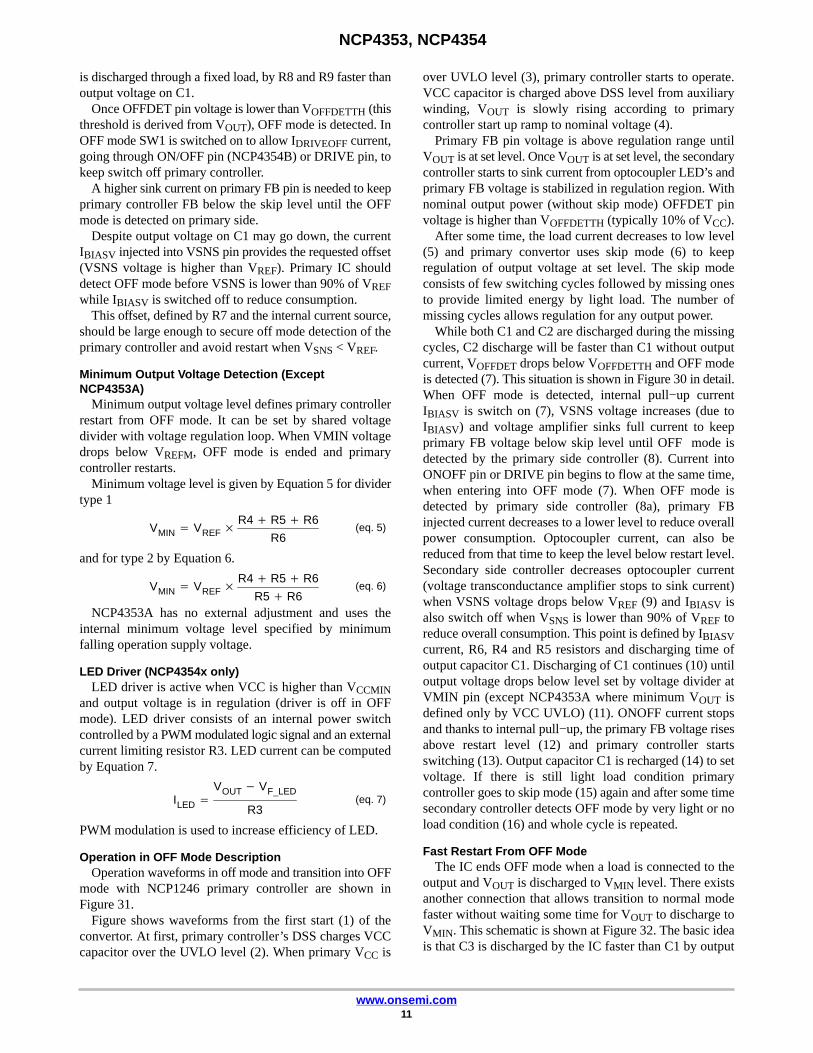
is discharged through a fixed load, by R8 and R9 faster thanoutput voltage on C1.
Once OFFDET pin voltage is lower than VOFFDETTH (thisthreshold is derived from VOUT), OFF mode is detected. InOFF mode SW1 is switched on to allow IDRIVEOFF current,going through ON/OFF pin (NCP4354B) or DRIVE pin, tokeep switch off primary controller.
A higher sink current on primary FB pin is needed to keepprimary controller FB below the skip level until the OFFmode is detected on primary side.
Despite output voltage on C1 may go down, the currentIBIASV injected into VSNS pin provides the requested offset(VSNS voltage is higher than VREF). Primary IC shoulddetect OFF mode before VSNS is lower than 90% of VREFwhile IBIASV is switched off to reduce consumption.
This offset, defined by R7 and the internal current source,should be large enough to secure off mode detection of theprimary controller and avoid restart when VSNS < VREF.
Minimum Output Voltage Detection (ExceptNCP4353A)
Minimum output voltage level defines primary controllerrestart from OFF mode. It can be set by shared voltagedivider with voltage regulation loop. When VMIN voltagedrops below VREFM, OFF mode is ended and primarycontroller restarts.
Minimum voltage level is given by Equation 5 for dividertype 1
VMIN � VREF �R4 � R5 � R6
R6(eq. 5)
and for type 2 by Equation 6.
VMIN � VREF �R4 � R5 � R6
R5 � R6(eq. 6)
NCP4353A has no external adjustment and uses theinternal minimum voltage level specified by minimumfalling operation supply voltage.
LED Driver (NCP4354x only)LED driver is active when VCC is higher than VCCMIN
and output voltage is in regulation (driver is off in OFFmode). LED driver consists of an internal power switchcontrolled by a PWM modulated logic signal and an externalcurrent limiting resistor R3. LED current can be computedby Equation 7.
ILED �VOUT � VF_LED
R3(eq. 7)
PWM modulation is used to increase efficiency of LED.
Operation in OFF Mode DescriptionOperation waveforms in off mode and transition into OFF
mode with NCP1246 primary controller are shown inFigure 31.
Figure shows waveforms from the first start (1) of theconvertor. At first, primary controller’s DSS charges VCCcapacitor over the UVLO level (2). When primary VCC is
over UVLO level (3), primary controller starts to operate.VCC capacitor is charged above DSS level from auxiliarywinding, VOUT is slowly rising according to primarycontroller start up ramp to nominal voltage (4).
Primary FB pin voltage is above regulation range untilVOUT is at set level. Once VOUT is at set level, the secondarycontroller starts to sink current from optocoupler LED’s andprimary FB voltage is stabilized in regulation region. Withnominal output power (without skip mode) OFFDET pinvoltage is higher than VOFFDETTH (typically 10% of VCC).
After some time, the load current decreases to low level(5) and primary convertor uses skip mode (6) to keepregulation of output voltage at set level. The skip modeconsists of few switching cycles followed by missing onesto provide limited energy by light load. The number ofmissing cycles allows regulation for any output power.
While both C1 and C2 are discharged during the missingcycles, C2 discharge will be faster than C1 without outputcurrent, VOFFDET drops below VOFFDETTH and OFF modeis detected (7). This situation is shown in Figure 30 in detail.When OFF mode is detected, internal pull−up currentIBIASV is switch on (7), VSNS voltage increases (due toIBIASV) and voltage amplifier sinks full current to keepprimary FB voltage below skip level until OFF mode isdetected by the primary side controller (8). Current intoONOFF pin or DRIVE pin begins to flow at the same time,when entering into OFF mode (7). When OFF mode isdetected by primary side controller (8a), primary FBinjected current decreases to a lower level to reduce overallpower consumption. Optocoupler current, can also bereduced from that time to keep the level below restart level.Secondary side controller decreases optocoupler current(voltage transconductance amplifier stops to sink current)when VSNS voltage drops below VREF (9) and IBIASV isalso switch off when VSNS is lower than 90% of VREF toreduce overall consumption. This point is defined by IBIASVcurrent, R6, R4 and R5 resistors and discharging time ofoutput capacitor C1. Discharging of C1 continues (10) untiloutput voltage drops below level set by voltage divider atVMIN pin (except NCP4353A where minimum VOUT isdefined only by VCC UVLO) (11). ONOFF current stopsand thanks to internal pull−up, the primary FB voltage risesabove restart level (12) and primary controller startsswitching (13). Output capacitor C1 is recharged (14) to setvoltage. If there is still light load condition primarycontroller goes to skip mode (15) again and after some timesecondary controller detects OFF mode by very light or noload condition (16) and whole cycle is repeated.
Fast Restart From OFF ModeThe IC ends OFF mode when a load is connected to the
output and VOUT is discharged to VMIN level. There existsanother connection that allows transition to normal modefaster without waiting some time for VOUT to discharge toVMIN. This schematic is shown at Figure 32. The basic ideais that C3 is discharged by the IC faster than C1 by output

NCP4353, NCP4354
www.onsemi.com12
load in OFF mode. When an output load is applied, capacitorC1 is discharged faster and this creates a voltage drop at D8.When there is enough voltage at D8, T2 is opened andcurrent is injected into the OFFDET divider through R17.OFFDET voltage higher than 10% of VCC ends OFF modeand ON/OFF current stops. Primary controller leaves OFF
mode because voltage at its FB pin rises above OFF modeend level and switching resumes.
Normal operation waveforms for typical load detectionconnection and improved load detection waveforms areshown in Figure 33.
SW1
Feedback&
ON / OFFOpto
D1
C1 C2 VOUT
OFF SupplyD2
R4
R2
R5
R6
R8
VREF
VREFM
VCC
managementPowerRESET
VDD
VoltageRegulation
Off ModeDetection
C4
R10
R9
IDRIVEOFF
R7
SW3
IBIASV
VDD
PowerRESET
OTA
VCC
VSNS
GND
OFFDET
Min OutputVoltage
DRIVE Sink only
VMIN
VREF
IBIASV
Enabling
0.9 x VREF
VCC
Power RESET
S
R
Q
Q
10%VCC
C3
R1
Figure 27. Typical Application Schematic for NCP4353B
SW1
Feedback&
ON / OFFOpto
D1
C1 C2 VOUT
OFF SupplyD2
R4
R2
R5
R6
R8
VREF
VREFM
VCC
managementPowerRESET
VDD
VoltageRegulation
Off ModeDetection
C4
R10
R9
1 kHz, 12% D.C.Oscillator
IDRIVEOFF
R7
SW3
IBIASV
VREFC
CurrentRegulation
OTA
R12VDD
PowerRESET
OTA
C5
R11
VCC ISNS
SW2
ON / OFFLED
R3LED
VSNS
GND
OFFDET
Min OutputVoltage
ON/OFF
FBC
Sink only
Sink only
VMIN
VREF
R13
IBIASV
Enabling
0.9 x VREF
VCC
Power RESET
S
R
Q
Q
10%VCC
R1
C3
Figure 28. Typical Application Schematic for All Features

NCP4353, NCP4354
www.onsemi.com13
D1
C1 C2
VOUT
D2
R4
R2
R5
R6
R8
C4R10
R9R7
GND
OFFDET
DRIVE VMIN
~
VCC
FBGND
DRV
CS
HV
VCC
VCC
OPTO1
C3
R14
C6
C7
C8
D3
T1
R15
D4
D5
NCP4353B
VIN
VCC
VSNS
D6
D7
R1
Figure 29. Typical Application Schematic for NCP4353B with Flyback
PrimaryController
Activity
VOFFDET
10% VOUT(VCC)
IOUT
Very low or no load detected,
off mode activated
Normal operation Skip Off mode
Figure 30. OFF Mode Detection

NCP4353, NCP4354
www.onsemi.com14
Figure 31. Typical Application States and Waveforms in OFF Mode with NCP1246 Primary Controller
D1
C1 C2
VOUT
D2
R4
R2
R5
R6
R8
C4R10
R9
R7R3LED
VSNSGND
OFFDET
FBC VMIN
LED1
OPTO1
C3
NCP4354B
ON/OFF
VCC
D8
R17
R16
T2
Figure 32. Improved Load Detection Connection

NCP4353, NCP4354
www.onsemi.com15
Figure 33. Typical and Improved Load Detection Comparison Waveforms
ORDERING INFORMATION
Device MarkingAdjustable
Vmin
CurrentRegulation
LEDDriver Package Shipping†
NCP4353ASNT1G A53 No Yes No TSOP−6(Pb−Free)
3000 / Tape & Reel
NCP4353BSNT1G B53 Yes No No TSOP−6(Pb−Free)
3000 / Tape & Reel
NCP4354ADR2G NCP4354A Yes Yes Yes SOIC−8(Pb−Free)
2500 / Tape & Reel
NCP4354BDR2G NCP4354B Yes No Yes SOIC−8(Pb−Free)
2500 / Tape & Reel
†For information on tape and reel specifications, including part orientation and tape sizes, please refer to our Tape and Reel PackagingSpecifications Brochure, BRD8011/D.
ÉÉÉÉ
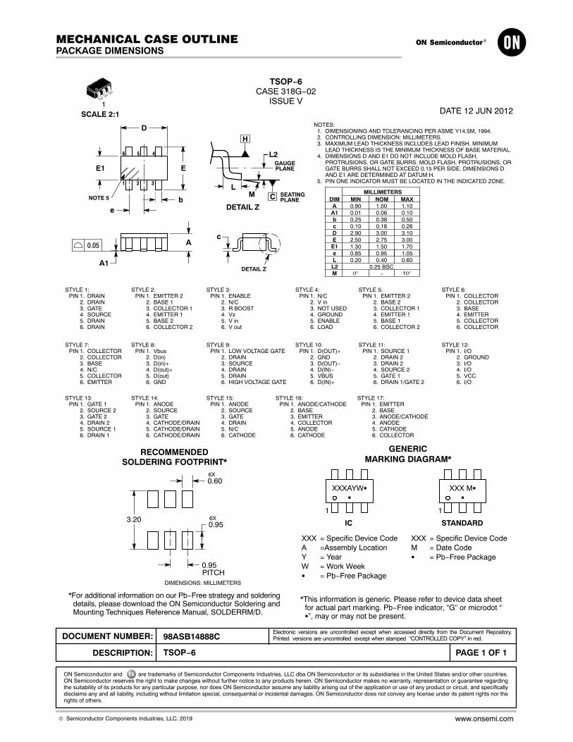
TSOP−6CASE 318G−02
ISSUE VDATE 12 JUN 2012SCALE 2:1
STYLE 1:PIN 1. DRAIN
2. DRAIN3. GATE4. SOURCE5. DRAIN6. DRAIN
2 3
456
D
1
eb
E1
A1
A0.05
NOTES:1. DIMENSIONING AND TOLERANCING PER ASME Y14.5M, 1994.2. CONTROLLING DIMENSION: MILLIMETERS.3. MAXIMUM LEAD THICKNESS INCLUDES LEAD FINISH. MINIMUM
LEAD THICKNESS IS THE MINIMUM THICKNESS OF BASE MATERIAL.4. DIMENSIONS D AND E1 DO NOT INCLUDE MOLD FLASH,
PROTRUSIONS, OR GATE BURRS. MOLD FLASH, PROTRUSIONS, ORGATE BURRS SHALL NOT EXCEED 0.15 PER SIDE. DIMENSIONS DAND E1 ARE DETERMINED AT DATUM H.
5. PIN ONE INDICATOR MUST BE LOCATED IN THE INDICATED ZONE.
c
STYLE 2:PIN 1. EMITTER 2
2. BASE 13. COLLECTOR 14. EMITTER 15. BASE 26. COLLECTOR 2
STYLE 3:PIN 1. ENABLE
2. N/C3. R BOOST4. Vz5. V in6. V out
STYLE 4:PIN 1. N/C
2. V in3. NOT USED4. GROUND5. ENABLE6. LOAD
XXX M�
�
XXX = Specific Device CodeA =Assembly LocationY = YearW = Work Week� = Pb−Free Package
STYLE 5:PIN 1. EMITTER 2
2. BASE 23. COLLECTOR 14. EMITTER 15. BASE 16. COLLECTOR 2
STYLE 6:PIN 1. COLLECTOR
2. COLLECTOR3. BASE4. EMITTER5. COLLECTOR6. COLLECTOR
STYLE 7:PIN 1. COLLECTOR
2. COLLECTOR3. BASE4. N/C5. COLLECTOR6. EMITTER
STYLE 8:PIN 1. Vbus
2. D(in)3. D(in)+4. D(out)+5. D(out)6. GND
GENERICMARKING DIAGRAM*
STYLE 9:PIN 1. LOW VOLTAGE GATE
2. DRAIN3. SOURCE4. DRAIN5. DRAIN6. HIGH VOLTAGE GATE
STYLE 10:PIN 1. D(OUT)+
2. GND3. D(OUT)−4. D(IN)−5. VBUS6. D(IN)+
1
1
*For additional information on our Pb−Free strategy and solderingdetails, please download the ON Semiconductor Soldering andMounting Techniques Reference Manual, SOLDERRM/D.
SOLDERING FOOTPRINT*
STYLE 11:PIN 1. SOURCE 1
2. DRAIN 23. DRAIN 24. SOURCE 25. GATE 16. DRAIN 1/GATE 2
STYLE 12:PIN 1. I/O
2. GROUND3. I/O4. I/O5. VCC6. I/O
*This information is generic. Please refer to device data sheetfor actual part marking. Pb−Free indicator, “G” or microdot “�”, may or may not be present.
XXXAYW�
�
1
STANDARDIC
XXX = Specific Device CodeM = Date Code� = Pb−Free Package
DIMA
MIN NOM MAXMILLIMETERS
0.90 1.00 1.10A1 0.01 0.06 0.10b 0.25 0.38 0.50c 0.10 0.18 0.26D 2.90 3.00 3.10E 2.50 2.75 3.00
e 0.85 0.95 1.05L 0.20 0.40 0.60
0.25 BSCL2−0° 10°
STYLE 13:PIN 1. GATE 1
2. SOURCE 23. GATE 24. DRAIN 25. SOURCE 16. DRAIN 1
STYLE 14:PIN 1. ANODE
2. SOURCE3. GATE4. CATHODE/DRAIN5. CATHODE/DRAIN6. CATHODE/DRAIN
STYLE 15:PIN 1. ANODE
2. SOURCE3. GATE4. DRAIN5. N/C6. CATHODE
1.30 1.50 1.70E1
E
RECOMMENDED
NOTE 5
LCM
H
L2
SEATINGPLANE
GAUGEPLANE
DETAIL Z
DETAIL Z
0.606X
3.200.956X
0.95PITCH
DIMENSIONS: MILLIMETERS
M
STYLE 16:PIN 1. ANODE/CATHODE
2. BASE3. EMITTER4. COLLECTOR5. ANODE6. CATHODE
STYLE 17:PIN 1. EMITTER
2. BASE3. ANODE/CATHODE4. ANODE5. CATHODE6. COLLECTOR
MECHANICAL CASE OUTLINE
PACKAGE DIMENSIONS
ON Semiconductor and are trademarks of Semiconductor Components Industries, LLC dba ON Semiconductor or its subsidiaries in the United States and/or other countries.ON Semiconductor reserves the right to make changes without further notice to any products herein. ON Semiconductor makes no warranty, representation or guarantee regardingthe suitability of its products for any particular purpose, nor does ON Semiconductor assume any liability arising out of the application or use of any product or circuit, and specificallydisclaims any and all liability, including without limitation special, consequential or incidental damages. ON Semiconductor does not convey any license under its patent rights nor therights of others.
98ASB14888CDOCUMENT NUMBER:
DESCRIPTION:
Electronic versions are uncontrolled except when accessed directly from the Document Repository.Printed versions are uncontrolled except when stamped “CONTROLLED COPY” in red.
PAGE 1 OF 1TSOP−6
© Semiconductor Components Industries, LLC, 2019 www.onsemi.com

SOIC−8 NBCASE 751−07
ISSUE AKDATE 16 FEB 2011
SEATINGPLANE
14
58
N
J
X 45�
K
NOTES:1. DIMENSIONING AND TOLERANCING PER
ANSI Y14.5M, 1982.2. CONTROLLING DIMENSION: MILLIMETER.3. DIMENSION A AND B DO NOT INCLUDE
MOLD PROTRUSION.4. MAXIMUM MOLD PROTRUSION 0.15 (0.006)
PER SIDE.5. DIMENSION D DOES NOT INCLUDE DAMBAR
PROTRUSION. ALLOWABLE DAMBARPROTRUSION SHALL BE 0.127 (0.005) TOTALIN EXCESS OF THE D DIMENSION ATMAXIMUM MATERIAL CONDITION.
6. 751−01 THRU 751−06 ARE OBSOLETE. NEWSTANDARD IS 751−07.
A
B S
DH
C
0.10 (0.004)
SCALE 1:1
STYLES ON PAGE 2
DIMA
MIN MAX MIN MAXINCHES
4.80 5.00 0.189 0.197
MILLIMETERS
B 3.80 4.00 0.150 0.157C 1.35 1.75 0.053 0.069D 0.33 0.51 0.013 0.020G 1.27 BSC 0.050 BSCH 0.10 0.25 0.004 0.010J 0.19 0.25 0.007 0.010K 0.40 1.27 0.016 0.050M 0 8 0 8 N 0.25 0.50 0.010 0.020S 5.80 6.20 0.228 0.244
−X−
−Y−
G
MYM0.25 (0.010)
−Z−
YM0.25 (0.010) Z S X S
M� � � �
XXXXX = Specific Device CodeA = Assembly LocationL = Wafer LotY = YearW = Work Week� = Pb−Free Package
GENERICMARKING DIAGRAM*
1
8
XXXXXALYWX
1
8
IC Discrete
XXXXXXAYWW
�1
8
1.520.060
7.00.275
0.60.024
1.2700.050
4.00.155
� mminches
�SCALE 6:1
*For additional information on our Pb−Free strategy and solderingdetails, please download the ON Semiconductor Soldering andMounting Techniques Reference Manual, SOLDERRM/D.
SOLDERING FOOTPRINT*
Discrete
XXXXXXAYWW
1
8
(Pb−Free)
XXXXXALYWX
�1
8
IC(Pb−Free)
XXXXXX = Specific Device CodeA = Assembly LocationY = YearWW = Work Week� = Pb−Free Package
*This information is generic. Please refer todevice data sheet for actual part marking.Pb−Free indicator, “G” or microdot “�”, mayor may not be present. Some products maynot follow the Generic Marking.
MECHANICAL CASE OUTLINE
PACKAGE DIMENSIONS
ON Semiconductor and are trademarks of Semiconductor Components Industries, LLC dba ON Semiconductor or its subsidiaries in the United States and/or other countries.ON Semiconductor reserves the right to make changes without further notice to any products herein. ON Semiconductor makes no warranty, representation or guarantee regardingthe suitability of its products for any particular purpose, nor does ON Semiconductor assume any liability arising out of the application or use of any product or circuit, and specificallydisclaims any and all liability, including without limitation special, consequential or incidental damages. ON Semiconductor does not convey any license under its patent rights nor therights of others.
98ASB42564BDOCUMENT NUMBER:
DESCRIPTION:
Electronic versions are uncontrolled except when accessed directly from the Document Repository.Printed versions are uncontrolled except when stamped “CONTROLLED COPY” in red.
PAGE 1 OF 2SOIC−8 NB
© Semiconductor Components Industries, LLC, 2019 www.onsemi.com

SOIC−8 NBCASE 751−07
ISSUE AKDATE 16 FEB 2011
STYLE 4:PIN 1. ANODE
2. ANODE3. ANODE4. ANODE5. ANODE6. ANODE7. ANODE8. COMMON CATHODE
STYLE 1:PIN 1. EMITTER
2. COLLECTOR3. COLLECTOR4. EMITTER5. EMITTER6. BASE7. BASE8. EMITTER
STYLE 2:PIN 1. COLLECTOR, DIE, #1
2. COLLECTOR, #13. COLLECTOR, #24. COLLECTOR, #25. BASE, #26. EMITTER, #27. BASE, #18. EMITTER, #1
STYLE 3:PIN 1. DRAIN, DIE #1
2. DRAIN, #13. DRAIN, #24. DRAIN, #25. GATE, #26. SOURCE, #27. GATE, #18. SOURCE, #1
STYLE 6:PIN 1. SOURCE
2. DRAIN3. DRAIN4. SOURCE5. SOURCE6. GATE7. GATE8. SOURCE
STYLE 5:PIN 1. DRAIN
2. DRAIN3. DRAIN4. DRAIN5. GATE6. GATE7. SOURCE8. SOURCE
STYLE 7:PIN 1. INPUT
2. EXTERNAL BYPASS3. THIRD STAGE SOURCE4. GROUND5. DRAIN6. GATE 37. SECOND STAGE Vd8. FIRST STAGE Vd
STYLE 8:PIN 1. COLLECTOR, DIE #1
2. BASE, #13. BASE, #24. COLLECTOR, #25. COLLECTOR, #26. EMITTER, #27. EMITTER, #18. COLLECTOR, #1
STYLE 9:PIN 1. EMITTER, COMMON
2. COLLECTOR, DIE #13. COLLECTOR, DIE #24. EMITTER, COMMON5. EMITTER, COMMON6. BASE, DIE #27. BASE, DIE #18. EMITTER, COMMON
STYLE 10:PIN 1. GROUND
2. BIAS 13. OUTPUT4. GROUND5. GROUND6. BIAS 27. INPUT8. GROUND
STYLE 11:PIN 1. SOURCE 1
2. GATE 13. SOURCE 24. GATE 25. DRAIN 26. DRAIN 27. DRAIN 18. DRAIN 1
STYLE 12:PIN 1. SOURCE
2. SOURCE3. SOURCE4. GATE5. DRAIN6. DRAIN7. DRAIN8. DRAIN
STYLE 14:PIN 1. N−SOURCE
2. N−GATE3. P−SOURCE4. P−GATE5. P−DRAIN6. P−DRAIN7. N−DRAIN8. N−DRAIN
STYLE 13:PIN 1. N.C.
2. SOURCE3. SOURCE4. GATE5. DRAIN6. DRAIN7. DRAIN8. DRAIN
STYLE 15:PIN 1. ANODE 1
2. ANODE 13. ANODE 14. ANODE 15. CATHODE, COMMON6. CATHODE, COMMON7. CATHODE, COMMON8. CATHODE, COMMON
STYLE 16:PIN 1. EMITTER, DIE #1
2. BASE, DIE #13. EMITTER, DIE #24. BASE, DIE #25. COLLECTOR, DIE #26. COLLECTOR, DIE #27. COLLECTOR, DIE #18. COLLECTOR, DIE #1
STYLE 17:PIN 1. VCC
2. V2OUT3. V1OUT4. TXE5. RXE6. VEE7. GND8. ACC
STYLE 18:PIN 1. ANODE
2. ANODE3. SOURCE4. GATE5. DRAIN6. DRAIN7. CATHODE8. CATHODE
STYLE 19:PIN 1. SOURCE 1
2. GATE 13. SOURCE 24. GATE 25. DRAIN 26. MIRROR 27. DRAIN 18. MIRROR 1
STYLE 20:PIN 1. SOURCE (N)
2. GATE (N)3. SOURCE (P)4. GATE (P)5. DRAIN6. DRAIN7. DRAIN8. DRAIN
STYLE 21:PIN 1. CATHODE 1
2. CATHODE 23. CATHODE 34. CATHODE 45. CATHODE 56. COMMON ANODE7. COMMON ANODE8. CATHODE 6
STYLE 22:PIN 1. I/O LINE 1
2. COMMON CATHODE/VCC3. COMMON CATHODE/VCC4. I/O LINE 35. COMMON ANODE/GND6. I/O LINE 47. I/O LINE 58. COMMON ANODE/GND
STYLE 23:PIN 1. LINE 1 IN
2. COMMON ANODE/GND3. COMMON ANODE/GND4. LINE 2 IN5. LINE 2 OUT6. COMMON ANODE/GND7. COMMON ANODE/GND8. LINE 1 OUT
STYLE 24:PIN 1. BASE
2. EMITTER3. COLLECTOR/ANODE4. COLLECTOR/ANODE5. CATHODE6. CATHODE7. COLLECTOR/ANODE8. COLLECTOR/ANODE
STYLE 25:PIN 1. VIN
2. N/C3. REXT4. GND5. IOUT6. IOUT7. IOUT8. IOUT
STYLE 26:PIN 1. GND
2. dv/dt3. ENABLE4. ILIMIT5. SOURCE6. SOURCE7. SOURCE8. VCC
STYLE 27:PIN 1. ILIMIT
2. OVLO3. UVLO4. INPUT+5. SOURCE6. SOURCE7. SOURCE8. DRAIN
STYLE 28:PIN 1. SW_TO_GND
2. DASIC_OFF3. DASIC_SW_DET4. GND5. V_MON6. VBULK7. VBULK8. VIN
STYLE 29:PIN 1. BASE, DIE #1
2. EMITTER, #13. BASE, #24. EMITTER, #25. COLLECTOR, #26. COLLECTOR, #27. COLLECTOR, #18. COLLECTOR, #1
STYLE 30:PIN 1. DRAIN 1
2. DRAIN 13. GATE 24. SOURCE 25. SOURCE 1/DRAIN 26. SOURCE 1/DRAIN 27. SOURCE 1/DRAIN 28. GATE 1
ON Semiconductor and are trademarks of Semiconductor Components Industries, LLC dba ON Semiconductor or its subsidiaries in the United States and/or other countries.ON Semiconductor reserves the right to make changes without further notice to any products herein. ON Semiconductor makes no warranty, representation or guarantee regardingthe suitability of its products for any particular purpose, nor does ON Semiconductor assume any liability arising out of the application or use of any product or circuit, and specificallydisclaims any and all liability, including without limitation special, consequential or incidental damages. ON Semiconductor does not convey any license under its patent rights nor therights of others.
98ASB42564BDOCUMENT NUMBER:
DESCRIPTION:
Electronic versions are uncontrolled except when accessed directly from the Document Repository.Printed versions are uncontrolled except when stamped “CONTROLLED COPY” in red.
PAGE 2 OF 2SOIC−8 NB
© Semiconductor Components Industries, LLC, 2019 www.onsemi.com

onsemi, , and other names, marks, and brands are registered and/or common law trademarks of Semiconductor Components Industries, LLC dba “onsemi” or its affiliatesand/or subsidiaries in the United States and/or other countries. onsemi owns the rights to a number of patents, trademarks, copyrights, trade secrets, and other intellectual property.A listing of onsemi’s product/patent coverage may be accessed at www.onsemi.com/site/pdf/Patent−Marking.pdf. onsemi reserves the right to make changes at any time to anyproducts or information herein, without notice. The information herein is provided “as−is” and onsemi makes no warranty, representation or guarantee regarding the accuracy of theinformation, product features, availability, functionality, or suitability of its products for any particular purpose, nor does onsemi assume any liability arising out of the application or useof any product or circuit, and specifically disclaims any and all liability, including without limitation special, consequential or incidental damages. Buyer is responsible for its productsand applications using onsemi products, including compliance with all laws, regulations and safety requirements or standards, regardless of any support or applications informationprovided by onsemi. “Typical” parameters which may be provided in onsemi data sheets and/or specifications can and do vary in different applications and actual performance mayvary over time. All operating parameters, including “Typicals” must be validated for each customer application by customer’s technical experts. onsemi does not convey any licenseunder any of its intellectual property rights nor the rights of others. onsemi products are not designed, intended, or authorized for use as a critical component in life support systemsor any FDA Class 3 medical devices or medical devices with a same or similar classification in a foreign jurisdiction or any devices intended for implantation in the human body. ShouldBuyer purchase or use onsemi products for any such unintended or unauthorized application, Buyer shall indemnify and hold onsemi and its officers, employees, subsidiaries, affiliates,and distributors harmless against all claims, costs, damages, and expenses, and reasonable attorney fees arising out of, directly or indirectly, any claim of personal injury or deathassociated with such unintended or unauthorized use, even if such claim alleges that onsemi was negligent regarding the design or manufacture of the part. onsemi is an EqualOpportunity/Affirmative Action Employer. This literature is subject to all applicable copyright laws and is not for resale in any manner.
PUBLICATION ORDERING INFORMATIONTECHNICAL SUPPORTNorth American Technical Support:Voice Mail: 1 800−282−9855 Toll Free USA/CanadaPhone: 011 421 33 790 2910
LITERATURE FULFILLMENT:Email Requests to: [email protected]
onsemi Website: www.onsemi.com
Europe, Middle East and Africa Technical Support:Phone: 00421 33 790 2910For additional information, please contact your local Sales Representative
◊