ncs protocol
DESCRIPTION
Understand the NCS protocolTRANSCRIPT

0ORCA RDT-8v 8.0 • Rev R© 2006 by Nuera Communications Inc.All Rights Reserved
Chapter 4NCS, Network Call Signaling
Chapter 4NCS, Network Call Signaling
1ORCA RDT-8v 8.0 • Rev R© 2006 by Nuera Communications Inc.All Rights Reserved
1NCS
NCS Protocol
IAD
Local IP
Network
NCS msgs
ORCA RDTPSTN
V5.2 LE
NCS msgs
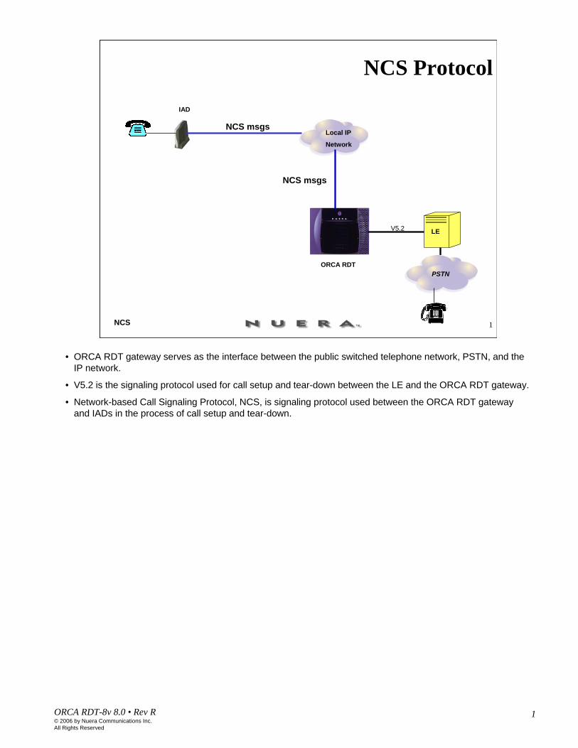
• ORCA RDT gateway serves as the interface between the public switched telephone network, PSTN, and the IP network.
• V5.2 is the signaling protocol used for call setup and tear-down between the LE and the ORCA RDT gateway.
• Network-based Call Signaling Protocol, NCS, is signaling protocol used between the ORCA RDT gateway and IADs in the process of call setup and tear-down.
2ORCA RDT-8v 8.0 • Rev R© 2006 by Nuera Communications Inc.All Rights Reserved
2NCS
Endpoint NamesNCS:
For analog access lines endpoint names are:Local_endpoint_name@domain_name
aaln/0@domain_nameaaln/1@domain_nameaaln/2@domain_name
Endpoint names on the gateway side:MGCP:
<Slot#>/<port#>/<channel#>@gateway_nameport = span number
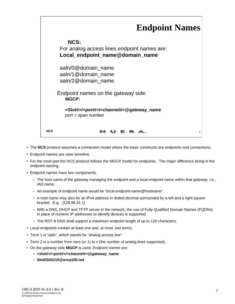
• The NCS protocol assumes a connection model where the basic constructs are endpoints and connections.
• Endpoint names are case sensitive.
• For the most part the NCS protocol follows the MGCP model for endpoints. The major difference being in the endpoint naming.
• Endpoint names have two components.
• The host name of the gateway managing the endpoint and a local endpoint name within that gateway, i.e., IAD name.
• An example of endpoint name would be “local-endpoint-name@hostname”.
• A host name may also be an IPv4 address in dotted decimal surrounded by a left and a right square bracket. E.g. : [128.96.41.1]
• With a DNS, DHCP and TFTP server in the network, the use of Fully Qualified Domain Names (FQDNs) in place of numeric IP addresses to identify devices is supported.
• The RDT-8 DNS shall support a maximum endpoint length of up to 128 characters.
• Local endpoints contain at least one and, at most, two terms.
• Term 1 is “aaln”, which stands for “analog access line”.
• Term 2 is a number from zero (or 1) to n (the number of analog lines supported).• On the gateway side MGCP is used. Endpoint names are:
• <slot#>/<port#>/<channel#>@gateway_name• Slot03/d1/[email protected]
3ORCA RDT-8v 8.0 • Rev R© 2006 by Nuera Communications Inc.All Rights Reserved
3NCS
NCS Connection Model
V 5.2
Interface Bundle (2-16 DS1)
PSTN
ORCA RDT
Local Exchange
IP Networkaaln/[email protected]
aaln/[email protected]
aaln/2@IAD2. tesla.net
aaln/1@IAD3. tesla.net
aaln/1@IAD4. tesla.net
Domain Name Server
LE
...
Connections
UPM4
IAD1
IAD2
IAD3
IAD4
1 2 3 4 5 6
7 8 9 1 0 1 11 2
AB
1 2 x
6 x
8 x
2 x
9 x
3 x
1 0x
4 x
1 1 x
5 x
7 x
1 x
Et
her
ne
t
A
1 2 x
6 x
8 x
2 x
9 x
3 x
1 0 x
4 x
1 1 x
5 x
7 x
1 x
C
Residential Area
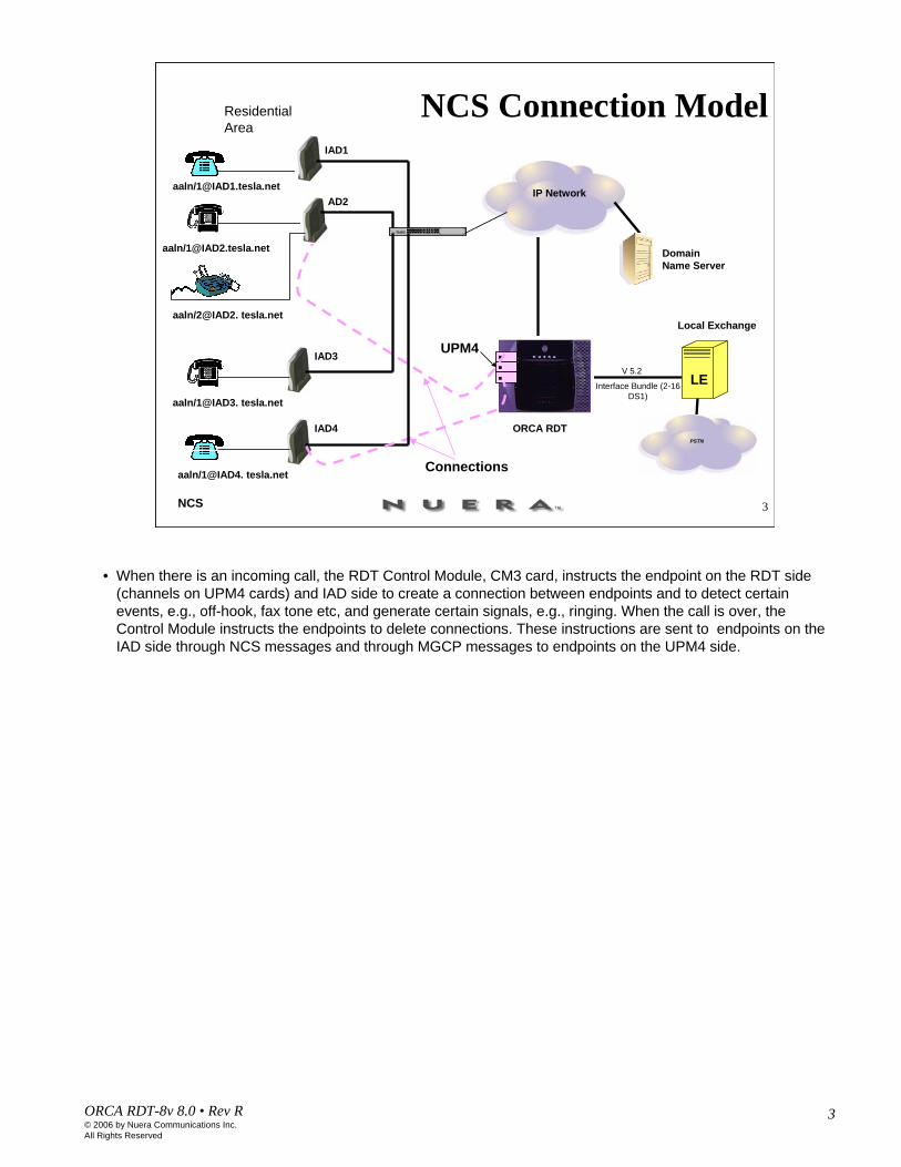
• When there is an incoming call, the RDT Control Module, CM3 card, instructs the endpoint on the RDT side (channels on UPM4 cards) and IAD side to create a connection between endpoints and to detect certain events, e.g., off-hook, fax tone etc, and generate certain signals, e.g., ringing. When the call is over, the Control Module instructs the endpoints to delete connections. These instructions are sent to endpoints on the IAD side through NCS messages and through MGCP messages to endpoints on the UPM4 side.

4ORCA RDT-8v 8.0 • Rev R© 2006 by Nuera Communications Inc.All Rights Reserved
4NCS
NCS Messages (1)
Command and Response MessagesCommand Messages
Audit Endpoint, AUEPCreate Connection, CRCXDelete Connection, DLCXModify Connection, MDCXNotify, NTFYNotification Request, RQNTRestart in Progress, RSIP
• Endpoints
• NCS assumes a connection model where the basic constructs are end points and connections. End points which are sources of data can be either physical or virtual.
Physical - A physical end point is a hardware port that can receive or send data.
Virtual - A Virtual end point is software generated data.
• Connections
• Connections can be either point to point or point to multi point. A connection exists where there is the ability to transmit data from one point to another within the same gateway or to another gateway.
• NCS messages: commands and response messages
• Command messages: Audit Endpoint, AUEP – Sent to find out the status of a given endpoint.
Create Connection, CRCX - Instructs the gateway to create a connection from the specified end point to another end point.
Modify connection, MDCX - to modify an existing connection parameter to the specified changes.
Delete Connection, DLCX - to delete a specified connection.
Notification Request, RQNT –to request notification of specified events.
Notify, NTFY –to notify that an event was observed. When a requested event is observed, a NTFY containing this observed event is sent.
Restart in Progress, RSIP –to indicate that an endpoint is either being taken out-of-service or being brought back in-service.

5ORCA RDT-8v 8.0 • Rev R© 2006 by Nuera Communications Inc.All Rights Reserved
5NCS
Format of NCS Command Messages
Verb transaction_ID end_point_name MGCP_version NCS_version
NTFY 040100009 aaln/0@[192.168.98.02] MGCP 1.0 NCS 1.0
CRCX 021440045 aaln/0@[192.168.98.02] MGCP 1.0 NCS 1.0
MGCP Command:
CRCX 028061389 slot3/d1/[email protected] MGCP 1.0

6ORCA RDT-8v 8.0 • Rev R© 2006 by Nuera Communications Inc.All Rights Reserved
6NCS
Notification Request Command
RQNT Transaction_ID Endpoint_name MGCP# NCS#[X: request Identifier][R: Requested Events][S: Signal Request]
• Endpoint_name is the identifier for the endpoint(s) in the gateway where NotificationRequest executes. The Endpoint_name must follow the rules for endpoints’ names explained earlier.
• RequestIdentifier is used to correlate this request with the notification it may trigger. It will be repeated in the corresponding Notify command.
• RequestedEvents is a list of events that the gateway is requested to detect on the endpoint. Examples of events are:
• fax tones,• modem tones,• on-hook transition (occurring in classic telephone sets when the user hangs up the handset), off-hook
transition (occurring in classic telephone sets when the user lifts the handset),• flash hook (occurring in classic telephone sets when the user briefly presses the hook that holds the
handset),• DTMF digits (or pulse digits).
• SignalRequests is a parameter that contains the set of signals that the gateway is asked to apply. Unless otherwise specified, signals are applied to the endpoint, however some signals can be applied to a connection. The following are examples of signals:
• Ringing,• Busy tone,• Call waiting tone,• Off hook warning tone,• Ringback tones on a connection

7ORCA RDT-8v 8.0 • Rev R© 2006 by Nuera Communications Inc.All Rights Reserved
7NCS
Notify Command
NTFY Transaction_ID Endpoint_name MGCP# NCS#[X: Request Identifier][O: Observed Events]
• Notifications are sent via the Notify command by the gateway when an observed event is to be notified.
• RequestIdentifier is a parameter that repeats the RequestIdentifier parameter of the NotificationRequest that triggered this notification. It is used to correlate this notification with the notification request that triggered it. Persistent events will be viewed here as if they had been included in the last NotificationRequest. When noNotificationRequest has been received, the RequestIdentifier used will be zero (“0”).
• ObservedEvents is a list of events that the gateway detected. A single notification can report a list of events that will be reported in the order in which they were detected. The list can only contain persistent events and events that were requested in the RequestedEvents parameter of the triggering NotificationRequest.

8ORCA RDT-8v 8.0 • Rev R© 2006 by Nuera Communications Inc.All Rights Reserved
8NCS
Create ConnectionCRCX Transaction_ID Endpoint_name MGCP# NCS#
[C: Call Id][L: Local Connection Options]
• Packetization Period, Vocoder, Silence suppression, Echo cancellation[X: Request Identifier][M: Mode][S: Signal Requests][R: Requested Events]Session Description Protocol parameters
• SDP Protocol Version• Connection Data• Media Announcement
UDP port on the UPM4 side is calculated based on the following formula:UDP = 100 * (DSX-1) + 2 * DS0 + 7000
• CallId is a parameter that identifies the call (or session) to which this connection belongs. This parameter is, at a minimum, unique within the collection of Call Agents that control the same gateways; connections that belong to the same call share the same call-id. The call-id can be used to identify calls for reporting and accounting purposes.
• LocalConnectionOptions is a structure that describes the characteristics of the media data connection
• Packetization Period - in milliseconds.
• Vocoder rate - compression algorithm used to send and receive media on the connection.
• Silence Suppression – “on” if silence suppression is enabled, or “off” if it is disabled.
• Echo Cancellation - can have the value “on” (when the echo cancellation is requested) or “off” (when it is turned off).
• Mode – can be “inactive”, “receive only”, “send/receive”.

9ORCA RDT-8v 8.0 • Rev R© 2006 by Nuera Communications Inc.All Rights Reserved
9NCS
Session Description Protocol
Session description: v= protocol version o= owner/creator and session identifiers= session name c= connection informationa= zero or more session attribute lines
Time description t= time the session is active
Media description m= media name and transport address a= zero or more media attribute lines
• An SDP session description consists of a number of lines of text of the form <type>=<value>. <type> is always exactly one character and is case-significant. <value> is a structured text string whose format depends on <type>.
• Time fields specify the start and stop times for a session.

10ORCA RDT-8v 8.0 • Rev R© 2006 by Nuera Communications Inc.All Rights Reserved
10NCS
Session Description Parameters
v=0o=<username> <session id> <version> <network type> <address type> <address> s=<session name>
c=<network type> <address type> <connection address>
• Session Description Protocol describes local/remote endpoint.
• Version – SDP version.
• Origin - gives the originator of the session.<username> is the user's login on the originating host, or it is "-" if the originating host does not support the concept of user ids.
<session id> is a numeric string such that the tuple of <username>, <session id>, <network type>, <address type> and <address> form a globally unique identifier for the session.
<version> is a version number for this announcement.
<network type> is a text string giving the type of network. "IN" means "Internet".
<address type> is a text string giving the type of the address that follows. Initially "IP4" and "IP6" are defined.
<address> is the globally unique address of the endpoint from which the session was created.
• Connection Data consists of 3 sub-fields:c= <network-type> <address-type> <connection-address>
c= IN IP4 10.10.111.11

11ORCA RDT-8v 8.0 • Rev R© 2006 by Nuera Communications Inc.All Rights Reserved
11NCS
Media Description Parametersm=<media> <port> <transport> <fmt list> a= <attribute> : <value>
a= rtpmap : <payload type> <encoding name>/<clock rate>
• a= rtpmap : 0 PCMU / 8000a = fmtp:<format><format specific parameters>
• a= fmtp: 127 0-15,144-159
• Media Announcements consists of 3 sub-fields:
• m= <media> <port> <transport> <format>
• m= audio 7002 RTP/AVP 0
• format - appropriate media payload type as defined in RFC 2327 (SDP).
• Attributes• rtpmap : <payload type> <encoding name>/<clock rate> • a = fmtp:<format><format specific parameters>
12ORCA RDT-8v 8.0 • Rev R© 2006 by Nuera Communications Inc.All Rights Reserved
12NCS
Modify ConnectionMDCX Transaction_ID Endpoint_name MGCP# NCS#
[C: Call Id][L: Local Connection Options]
• Packetization Period, Vocoder, Silence suppression, Echo cancellation[X: Request Identifier][I: Connection ID][M: Mode][S: Signal Requests][R: Requested Events]
Session Description Protocol parameters • SDP Protocol Version• Connection Data• Media Announcement
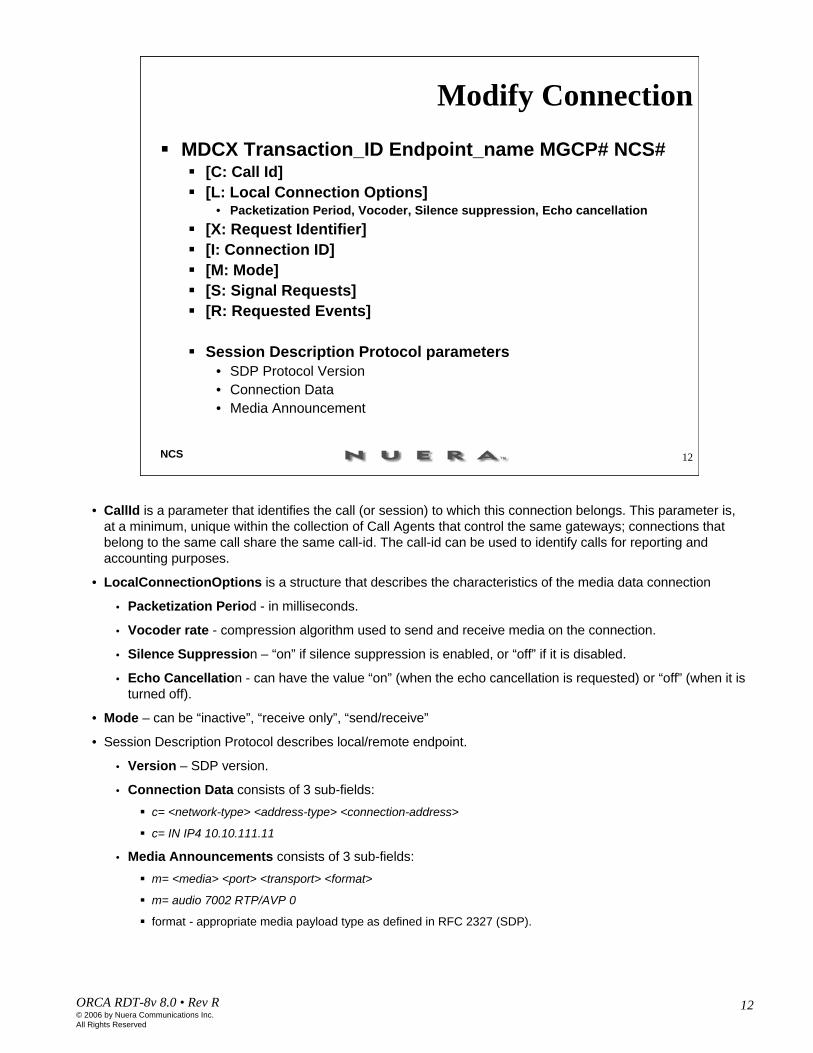
• CallId is a parameter that identifies the call (or session) to which this connection belongs. This parameter is, at a minimum, unique within the collection of Call Agents that control the same gateways; connections that belong to the same call share the same call-id. The call-id can be used to identify calls for reporting and accounting purposes.
• LocalConnectionOptions is a structure that describes the characteristics of the media data connection
• Packetization Period - in milliseconds.
• Vocoder rate - compression algorithm used to send and receive media on the connection.
• Silence Suppression – “on” if silence suppression is enabled, or “off” if it is disabled.
• Echo Cancellation - can have the value “on” (when the echo cancellation is requested) or “off” (when it is turned off).
• Mode – can be “inactive”, “receive only”, “send/receive”
• Session Description Protocol describes local/remote endpoint.
• Version – SDP version.
• Connection Data consists of 3 sub-fields:c= <network-type> <address-type> <connection-address>
c= IN IP4 10.10.111.11
• Media Announcements consists of 3 sub-fields:m= <media> <port> <transport> <format>
m= audio 7002 RTP/AVP 0
format - appropriate media payload type as defined in RFC 2327 (SDP).

13ORCA RDT-8v 8.0 • Rev R© 2006 by Nuera Communications Inc.All Rights Reserved
13NCS
Restart in Progress
RSIP Transaction_ID Endpoint_name MGCP# NCS#[RM: Restart Method][RD: Restart Delay]
Sent from a gateway, MG, to the call agent, MGC.
•This command is used by the gateway to signal that an endpoint is taken in or out of service.
•RestartDelay is expressed in seconds. If the number is not present the delay value is null.
•The RestartMethod parameter specifies the type of restart. The following restart methods are supported:
•Forced – indicates that the specified endpoints are taken abruptly out of service and the established connections are lost.
•Restart – indicates that service will be restored on the endpoints after the specified restart delay. A restart delay of null for the restart method indicates that service has been already restored. This will typically occur after gateway startup/reboot.
•Disconnected – indicates that the endpoint has become disconnected and is now trying to establish connectivity.

14ORCA RDT-8v 8.0 • Rev R© 2006 by Nuera Communications Inc.All Rights Reserved
14NCS
Delete Connection from MGC
DLCX Transaction_ID Endpoint_name MGCP# NCS#[C: Call Id][I: Connection ID][N: NotifiedEntity][R: RequestedEvents][X RequestIdentifier][S: SignalRequests]
•This command is used to terminate a connection and it collects statistics on the execution of the connection.
•The NotifiedEntity, RequestedEvents, RequestIdentifier, SignalRequests, QuarantineHandling, andDetectEvents parameters are optional. They can be used by the MGC to transmit a notification request that is tied to and executed simultaneously with the deletion of the connection. However, if one or more of these parameters are present, RequestIdentifier MUST be one of them.

15ORCA RDT-8v 8.0 • Rev R© 2006 by Nuera Communications Inc.All Rights Reserved
15NCS
Delete Connection from MG
DLCX Transaction_ID Endpoint_name MGCP# NCS#[C: Call Id][I: Connection ID][E: Reason-code][P: Connection-parameters]
• This command is used to terminate a connection and it collects statistics on the execution of the connection.
• The Reason-code is a text string starting with a numeric reason-code and optionally followed by a descriptive text string. Reason-codes are used by the gateway when deleting a connection to inform the MGC about the reason for deleting the connection. The reason code is an integer number, and the following values have been defined:
• 000 Endpoint state is nominal. (This code is used only in response to audit requests.)
• 901 Endpoint taken out of service
• 902 Loss of lower layer connectivity (e.g., downstream sync) i.e., T1 or E1 is down or is experiencing red alarms. Usually 902 is seen in the RSIP message when there is no connection associated with the endpoint reporting RSIP. If the endpoints have existing connections, and are experiencing a RED alarm, then DLCX will be used, and followed by RSIP.

16ORCA RDT-8v 8.0 • Rev R© 2006 by Nuera Communications Inc.All Rights Reserved
16NCS
Audit Endpoint
AUEP Transaction_ID Endpoint_name MGCP# NCS#[F:RequestedInfo]
• The AuditEndPoint, AUEP, command can be used by the Call Agent to find out the status of a given endpoint.• RequestedInfo describes the information that is requested for the specified endpoint. Several endpoint-
specific information can then be audited with this command. Nuera RDT uses it to audit ConnectionIdentifiers.• ConnectionIdentifiers - A comma-separated list of ConnectionIdentifiers for all connections that currently
exist for the specified endpoint.• AUEP (F:I)• A problem has been identified interoperating with certain IADs. The issue arises if the RDT loses
communication with the endpoint while a call is active. This can happen either through an IP fault or through a power-cycle of the RDT.
• The problem is that the IAD has a connection that the RDT does not know about. When a new connection is attempted we need to remove the old one. Most IADs will reject a second connection to an endpoint, in which case the RDT will send a DLCX to remove the first connection and then retry with the new connection.
• However, some IADs will not reject a second connection, they will actually add it to the existing connection. In this case the result is multiple RTP streams, causing distortion on the audio path.
• The solution is to send an AUEP to each endpoint when bringing it online asking about active connections. If there are any, then a DLCX is sent to clear out the existing connection before bringing the endpoint into service.
17ORCA RDT-8v 8.0 • Rev R© 2006 by Nuera Communications Inc.All Rights Reserved
17NCS
NCS Messages (2) Response Messages
2xx Informational (successful completion)• 200 OK• 250 Connection deleted
4xx Transient error• 401 Already off hook• 402 Already on hook
5xx Permanent error• 500 Unknown endpoint 519 Missing digit map• 501 Endpoint not ready 520 Endpoint restarting• 502 Insufficient resource 521 Call redirected• 510 Protocol error 522 Unknown event
511 Unknown extension 523 Unknown action• 512 Not equipped to detect 524 Options inconsistent• 513 Not equipped to signal 525 Unknown options extension• 514 Announcement unsupported 526 Insufficient bandwidth• 515 Incorrect connection ID 527 Missing connection descriptor• 516 Unknown call ID 528 Protocol version error• 517 unknown mode 529 Invalid response• 518 Unknown package 530/531 CPR/UPM resend timeout
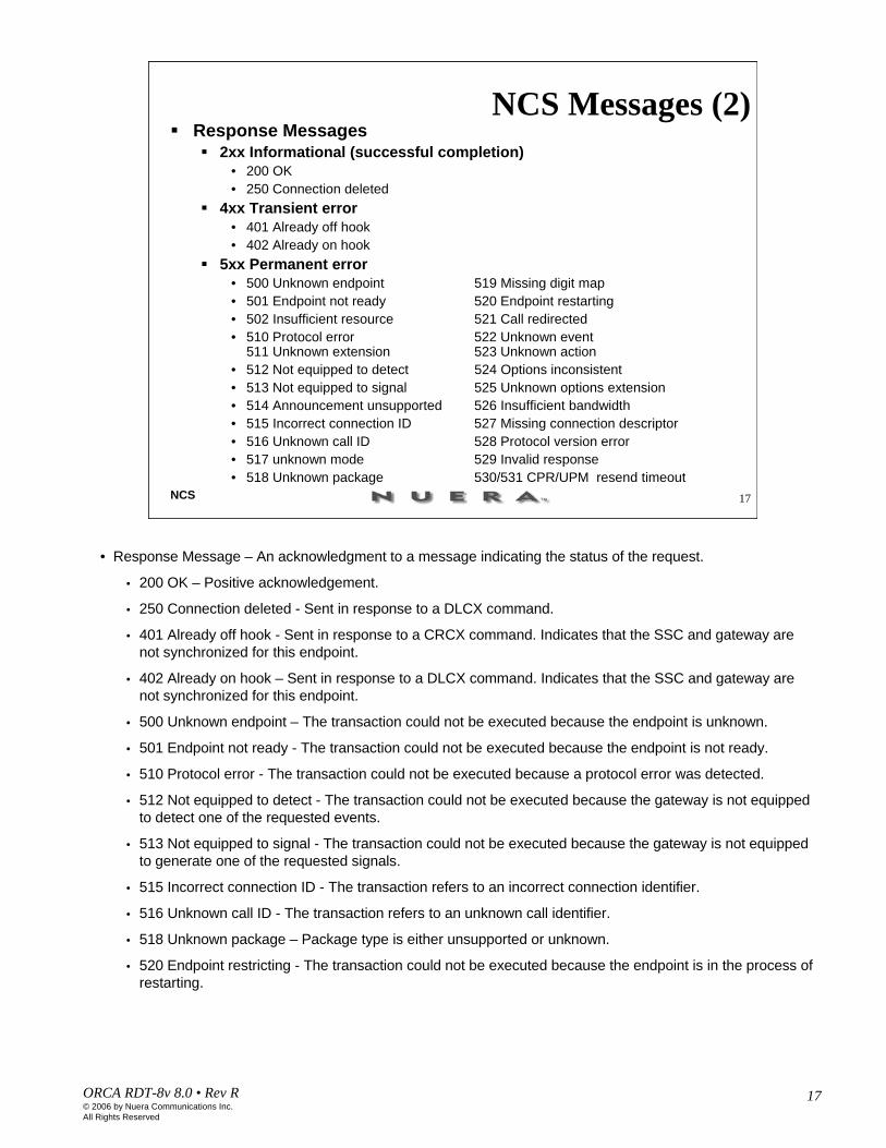
• Response Message – An acknowledgment to a message indicating the status of the request.
• 200 OK – Positive acknowledgement.
• 250 Connection deleted - Sent in response to a DLCX command.
• 401 Already off hook - Sent in response to a CRCX command. Indicates that the SSC and gateway are not synchronized for this endpoint.
• 402 Already on hook – Sent in response to a DLCX command. Indicates that the SSC and gateway are not synchronized for this endpoint.
• 500 Unknown endpoint – The transaction could not be executed because the endpoint is unknown.
• 501 Endpoint not ready - The transaction could not be executed because the endpoint is not ready.
• 510 Protocol error - The transaction could not be executed because a protocol error was detected.
• 512 Not equipped to detect - The transaction could not be executed because the gateway is not equipped to detect one of the requested events.
• 513 Not equipped to signal - The transaction could not be executed because the gateway is not equipped to generate one of the requested signals.
• 515 Incorrect connection ID - The transaction refers to an incorrect connection identifier.
• 516 Unknown call ID - The transaction refers to an unknown call identifier.
• 518 Unknown package – Package type is either unsupported or unknown.
• 520 Endpoint restricting - The transaction could not be executed because the endpoint is in the process of restarting.
18ORCA RDT-8v 8.0 • Rev R© 2006 by Nuera Communications Inc.All Rights Reserved
18NCS
Format of NCS Response Messages
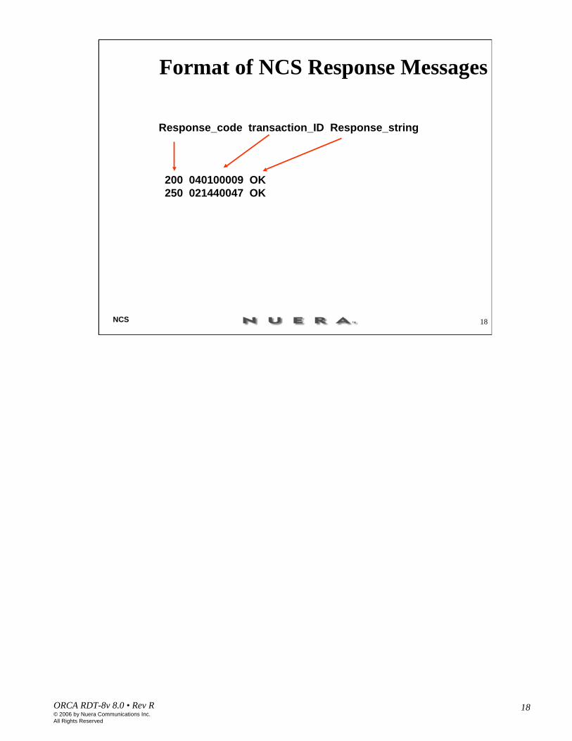
Response_code transaction_ID Response_string
200 040100009 OK250 021440047 OK
19ORCA RDT-8v 8.0 • Rev R© 2006 by Nuera Communications Inc.All Rights Reserved
19NCS
200 OK to Create Connection
200 Transaction_ID OKv=0o= = - 14 0 IN IP4 192.168.125.3s=-b=t=a=sendrecvIN IP4 192.168.59.22m=audio 7002 RTP/AVP 0a=ptime:10
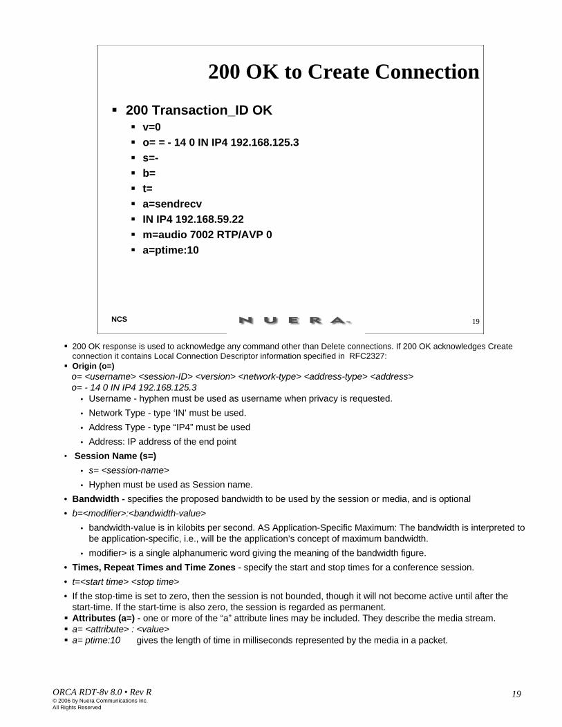
200 OK response is used to acknowledge any command other than Delete connections. If 200 OK acknowledges Create connection it contains Local Connection Descriptor information specified in RFC2327:Origin (o=)o= <username> <session-ID> <version> <network-type> <address-type> <address>o= - 14 0 IN IP4 192.168.125.3
• Username - hyphen must be used as username when privacy is requested. • Network Type - type ‘IN’ must be used.• Address Type - type “IP4” must be used• Address: IP address of the end point
• Session Name (s=)• s= <session-name>• Hyphen must be used as Session name.
• Bandwidth - specifies the proposed bandwidth to be used by the session or media, and is optional• b=<modifier>:<bandwidth-value>
• bandwidth-value is in kilobits per second. AS Application-Specific Maximum: The bandwidth is interpreted to be application-specific, i.e., will be the application’s concept of maximum bandwidth.
• modifier> is a single alphanumeric word giving the meaning of the bandwidth figure.• Times, Repeat Times and Time Zones - specify the start and stop times for a conference session.• t=<start time> <stop time>• If the stop-time is set to zero, then the session is not bounded, though it will not become active until after the
start-time. If the start-time is also zero, the session is regarded as permanent.Attributes (a=) - one or more of the “a” attribute lines may be included. They describe the media stream.a= <attribute> : <value>a= ptime:10 gives the length of time in milliseconds represented by the media in a packet.

20ORCA RDT-8v 8.0 • Rev R© 2006 by Nuera Communications Inc.All Rights Reserved
20NCS
Piggybacking
200 2005 OK.DLCX 1244 ds/ds1-2/[email protected] MGCP 1.0 TGCP
1.0C: A3C47F21456789F0I: FDE234C8
• There are cases when an MGC will want to send several messages at the same time to one or more endpoints in a gateway and vice versa. When several messages have to be sent in the same UDP packets, they are separated by a line of text that contain a single dot, as in the following example:
200 2005 OK
.
DLCX 1244 ds/ds1-2/[email protected] MGCP 1.0 TGCP 1.0
C: A3C47F21456789F0
I: FDE234C8
21ORCA RDT-8v 8.0 • Rev R© 2006 by Nuera Communications Inc.All Rights Reserved
21NCS
250 OK250 Transaction_ID OK
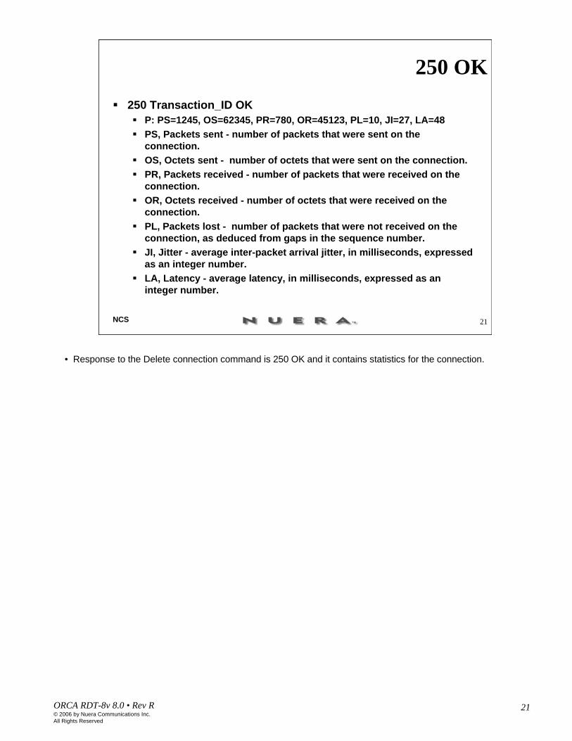
P: PS=1245, OS=62345, PR=780, OR=45123, PL=10, JI=27, LA=48PS, Packets sent - number of packets that were sent on the connection.OS, Octets sent - number of octets that were sent on the connection.PR, Packets received - number of packets that were received on the connection.OR, Octets received - number of octets that were received on the connection.PL, Packets lost - number of packets that were not received on the connection, as deduced from gaps in the sequence number.JI, Jitter - average inter-packet arrival jitter, in milliseconds, expressed as an integer number.LA, Latency - average latency, in milliseconds, expressed as an integer number.
• Response to the Delete connection command is 250 OK and it contains statistics for the connection.
22ORCA RDT-8v 8.0 • Rev R© 2006 by Nuera Communications Inc.All Rights Reserved
22NCS
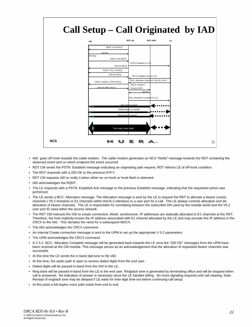
Call Setup – Call Originated by IADIAD RDT CM RDT UPM LE
200 OK (NCS)
Off HookNotify: O:hd (NCS)
200 OK SDP1 (NCS)CRCX: sendrecv
Remote SDP1
PSTN: Establish (V 5.2)
CRCX: sendrecv, SDP2 (NCS)
200 OK
BCC: Allocation Complete (V 5.2)
Dial Tone (in band)
RQNT: R:hd (NCS)
200 OK
RQNT: R:hu, hf (NCS)
200 OK (NCS)PSTN: Establish Ack; (V 5.2)
BCC: Allocation (channel #, link ID); (V5.2)
Two way voice path
Ring back (in band)
Dialed Digits (in band)
• IAD goes off hook towards the cable modem. The cable modem generates an NCS “Notify” message towards the RDT containing the observed event and on which endpoint the event occurred.
• RDT CM sends the PSTN: Establish message indicating an originating path request. RDT informs LE of off-hook condition.• The RDT responds with a 200 OK to the previous NTFY.• RDT CM requests IAD to notify it when either an on-hook or hook-flash is detected.• IAD acknowledges the RQNT.• The LE responds with a PSTN: Establish Ack message to the previous Establish message, indicating that the requested action was
performed.• The LE sends a BCC: Allocation message. The Allocation message is sent by the LE to request the RDT to allocate a bearer (voice)
channels ( V5.2 timeslots or E1 channels within theV5.2 interface) to a user port for a call. The LE always controls allocation and de-allocation of bearer channels. The LE is responsible for correlating between the subscriber DN used by the outside world and the V5.2 user port ID used within the access network.
• The RDT CM instructs the IAD to create connection, Mode: sendreceive. IP addresses are statically allocated to E1 channels at the RDT.Therefore, the host implicitly knows the IP address associated with E1 channel allocated by the LE and may provide this IP address in the CRCX to the IAD. This obviates the need for a subsequent MDCX.
• The IAD acknowledges the CRCX command.• An internal Create connection message is sent to the UPM to set up the appropriate V 5.2 parameters. • The UPM acknowledges the CRCX command.• A V 5.2 BCC: Allocation Complete message will be generated back towards the LE once the “200 OK” messages from the UPM have
been received at the CM module. This message serves as an acknowledgement that the allocation of requested bearer channels was successful.
• At this time the LE sends the in band dial tone to the IAD.• At this time, the audio path is open to receive dialed digits from the end user.• Dialed digits will be passed in-band from the IAD to the LE.• Ring back will be passed in-band from the LE to the end user. Ringback tone is generated by terminating office and will be stopped when
call is answered. No indication of answer is necessary since the LE handles billing. No more signaling required until call clearing. Note: Receipt of ringback tone may be delayed if LE waits for inter-digit time-out before continuing call setup.
• At this point a full duplex voice path exists from end to end.

23ORCA RDT-8v 8.0 • Rev R© 2006 by Nuera Communications Inc.All Rights Reserved
23NCS
Call Teardown (1) RDT CM RDT UPMIAD LE
On Hook
200 OK (NCS)
Notify: O:hu (NCS)
PSTN: Signal Ack (V 5.2)
DLCX (NCS)DLCX (NCS)
250 OK
250 OK (NCS)
BCC: De-allocation Complete (V 5.2)
PSTN: Disconnect Complete (V 5.2)
PSTN: Signal; (V 5.2)
PSTN: Disconnect (V 5.2)
BCC: De-allocation (V 5.2)
Two way voice path
• In this scenario the IAD hangs up first.• The IAD observes on-hook and sends a NTFY message to the RDT.• The RDT sends a PSTN: Signal message to the LE. This message indicates the user line on-hook condition.• The RDT acknowledges the previous NTFY message with 200 OK.• In response to the previous PSTN: Signal message the LE sends Signal Ack to acknowledge the Signal
message.• The LE sends a BCC: De-allocation message to de-allocate the bearer channel from the user port.The LE
always controls E1 channel de-allocation. BCC De-allocation and PSTN Disconnect may be received in either order. However, the BCC De-allocation message shall stimulate the DLCX to the IAD.
• The LE sends a PSTN: Disconnect message.• The RDT generates a Delete connection, DLCX, message both toward the IAD and internally toward the
UPM.• Each endpoint will respond with a 250 OK message which includes call statistics.• Once the connections have been deleted, the RDT generates a BCC: De-allocation Complete message
which is a positive acknowledgment that the requested bearer channel was successfully de-allocated.• The RDT sends a PSTN: Disconnect Complete message which indicates that the requested Disconnect
action was performed and the call has been disconnected.
24ORCA RDT-8v 8.0 • Rev R© 2006 by Nuera Communications Inc.All Rights Reserved
24NCS
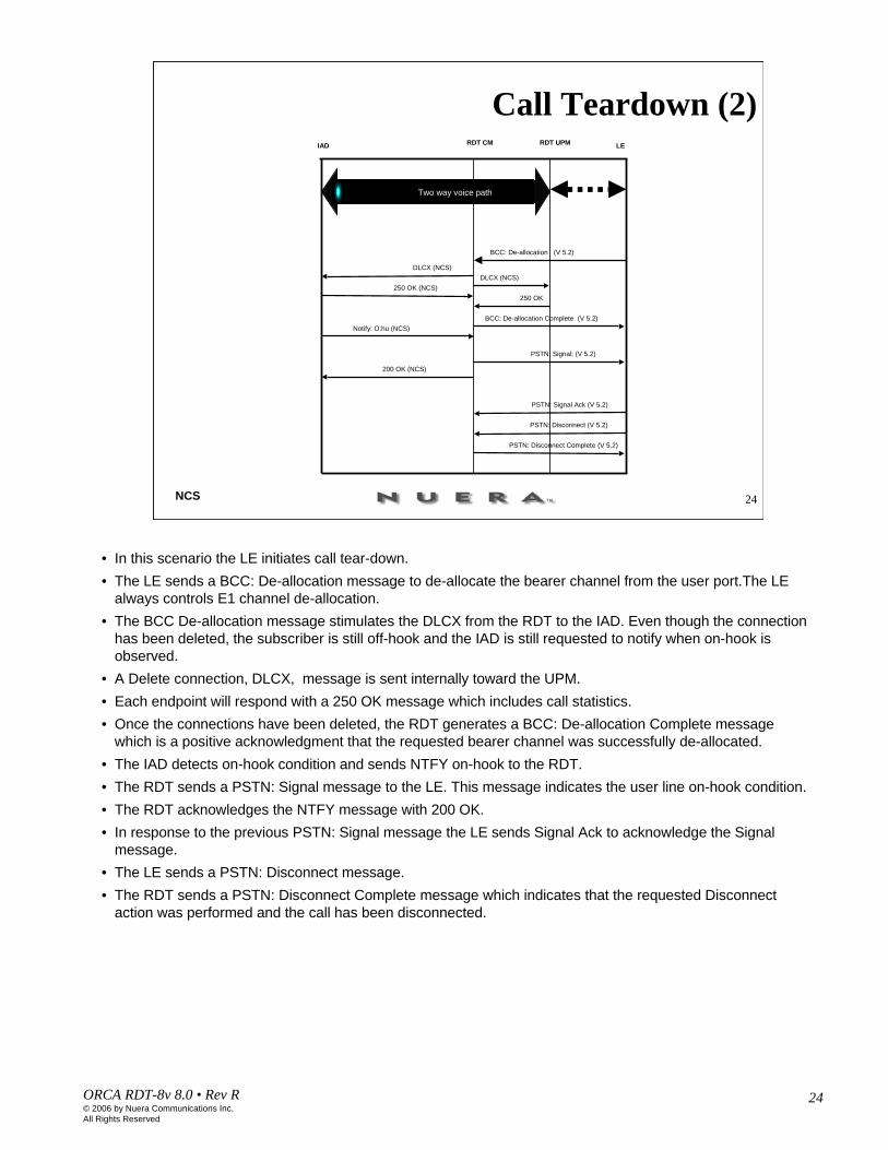
Call Teardown (2) RDT CM RDT UPMIAD LE
200 OK (NCS)
Notify: O:hu (NCS)
PSTN: Signal Ack (V 5.2)
DLCX (NCS)DLCX (NCS)
250 OK250 OK (NCS)
BCC: De-allocation Complete (V 5.2)
PSTN: Disconnect Complete (V 5.2)
PSTN: Signal; (V 5.2)
PSTN: Disconnect (V 5.2)
BCC: De-allocation (V 5.2)
Two way voice path
• In this scenario the LE initiates call tear-down.• The LE sends a BCC: De-allocation message to de-allocate the bearer channel from the user port.The LE
always controls E1 channel de-allocation. • The BCC De-allocation message stimulates the DLCX from the RDT to the IAD. Even though the connection
has been deleted, the subscriber is still off-hook and the IAD is still requested to notify when on-hook is observed.
• A Delete connection, DLCX, message is sent internally toward the UPM.• Each endpoint will respond with a 250 OK message which includes call statistics.• Once the connections have been deleted, the RDT generates a BCC: De-allocation Complete message
which is a positive acknowledgment that the requested bearer channel was successfully de-allocated.• The IAD detects on-hook condition and sends NTFY on-hook to the RDT.• The RDT sends a PSTN: Signal message to the LE. This message indicates the user line on-hook condition.• The RDT acknowledges the NTFY message with 200 OK.• In response to the previous PSTN: Signal message the LE sends Signal Ack to acknowledge the Signal
message.• The LE sends a PSTN: Disconnect message.• The RDT sends a PSTN: Disconnect Complete message which indicates that the requested Disconnect
action was performed and the call has been disconnected.

25ORCA RDT-8v 8.0 • Rev R© 2006 by Nuera Communications Inc.All Rights Reserved
Call Trace, Vocoder G.711 a
• [16:25:50.631]<---NTFY 57 aaln/1@[192.168.25.191] MGCP 1.0X: 81921028• O: L/hd• [16:25:50.631]<---200 57 OK
• [16:25:50.631]<---RQNT 81921029 aaln/1@[192.168.25.191] MGCP 1.0 NCS 1.0• X: 81921029• R: hu,hf
• [16:25:50.661]<---200 81921029 OK• [16:25:50.761]<---CRCX 81921030 aaln/1@[192.168.25.191] MGCP 1.0 NCS 1.0• C: 81921030• L: p:10, a:PCMA, s:off, e:on• X: 81921030• M: sendrecv
• v=0• o=- 1107706241 1107706241 IN IP4 192.168.25.140• s=-• c=IN IP4 192.168.25.141• t=0 0• m=audio 7006 RTP/AVP 8• a=mptime:10
• [16:25:50.781]<---200 81921030 OK• I: 17• v=0• o=InnoMedia_MGCP 3002 100 IN IP4 192.168.25.191• s=-• c=IN IP4 192.168.25.191• b=AS:107• t=0 0• m=audio 6024 RTP/AVP 8• a=ptime:10

26ORCA RDT-8v 8.0 • Rev R© 2006 by Nuera Communications Inc.All Rights Reserved
• [16:25:50.781]<---CRCX 81921031 slot03/d1/03@ MGCP 1.0 NCS 1.0• C: 81921031• L: a:PCMA, p:10, e:on, s:off, x-ns:off, x-emode:on/on• X: 81921031• M: sendrecv• R: mt, ft
• v=0• o=InnoMedia_MGCP 3002 100 IN IP4 192.168.25.191• s=-• c=IN IP4 192.168.25.191• b=AS:107• t=0 0• m=audio 6024 RTP/AVP 8• a=ptime:10
• [16:25:50.791]<---200 81921031 OK• I: 50000
• v=0• c=IN IP4 192.168.25.141• m=audio 7006 RTP/AVP 8• a=rtpmap:8 PCMA/8000• a=mptime:10
• [16:26:04.371]<---NTFY 58 aaln/1@[192.168.25.191] MGCP 1.0• X: 81921030• O: L/hu• [16:26:04.371]<---200 58 OK
• [16:26:04.371]<---RQNT 81921032 aaln/1@[192.168.25.191] MGCP 1.0 NCS 1.0• X: 81921032• R: hd
• [16:26:04.401]<---200 81921032 OK
• [16:26:04.441]<---DLCX 81921033 aaln/1@[192.168.25.191] MGCP 1.0 NCS 1.0• C: 81921030• I: 17

27ORCA RDT-8v 8.0 • Rev R© 2006 by Nuera Communications Inc.All Rights Reserved
• [16:26:04.441]<---DLCX 81921034 slot03/d1/03@ MGCP 1.0 NCS 1.0• C: 81921031• I: 50000
• [16:26:04.461]<---250 81921034 OK• P:
PS=1366,OS=109280,PR=1365,OR=109200,PL=0,JI=0,LA=206351,PC/RPS=1202,PC/ROS=96160,PC/RPL=1,PC/RJI=0
• [16:26:04.471]<---250 81921033 Conn Deleted• P: PS=1366, OS=109280, PR=1364, OR=109120, PL=0, JI=0, LA=0• [16:26:04.481]<---RQNT 81921035 aaln/1@[192.168.25.191] MGCP 1.0 NCS 1.0• X: 81921035• R: hd
• [16:26:04.501]<---200 81921035 OK

28ORCA RDT-8v 8.0 • Rev R© 2006 by Nuera Communications Inc.All Rights Reserved
IAD to IAD Call
IAD2 (sdp2)
RDT CM RDT UPM(sdp3)
LE
200 OK (NCS)
Off Hook Notify: O:hd (NCS)
200 OK sdp2 (NCS) CRCX: sdp2
PSTN: Establish (UserID=2, steady signal= off-hook (V5.2)
PSTN: Establish Ack (V5.2)
CRCX: sdp3, G.711 mode=sendrecv, (NCS),
200 OK
BCC: Allocation complete (V5.2)
Dial Tone (in band)
Dialed Digits (in band)
Ring back (in band)
RQNT: R:hu, hf (NCS)
200 OK (NCS)
RQNT: R:hd (NCS)
200 OK
18. Two way voice path
BCC: Allocation (UserID=2 channel #, link ID) (V5.2)
IAD1 (sdp1)
RDT UPM(sdp4)
RQNT: R:hd (NCS)200 OK
BCC: Allocation (UserID=1 channel #, link ID) (V5.2)CRCX: sdp4, G.711
200 OK: sdp1 (NCS)CRCX: sdp1, G.729a
200 OK
BCC: Allocation complete (V5.2)
PSTN: Establish (UserID=1, cadenced ring)
PSTN: Establish Ack (UserID=1) (V5.2)RQNT: S:r0, R:hd (NCS)
200 OK (NCS)
NTFY: O:hd (NCS)
200 OK (NCS)PSTN: Signal (UserID=1, steady-signal=off-hook)
200 OK (NCS)
PSTN: Signal (UserID=2, steady-signal=reversed polarity)
PSTN: Signal Ack (UserID=2)
PSTN: Signal Ack (UserID=1)
RQNT: R:hu,hf (NCS)
Off Hook

29ORCA RDT-8v 8.0 • Rev R© 2006 by Nuera Communications Inc.All Rights Reserved
IAD tp IAD Call Tear down
IAD2 (sdp2)
RDT CM RDT UPM(sdp3)
LE
200 OK (NCS)
Notify: O:hu (NCS)
250 OK (NCS)
PSTN: Signal (UserID=1, steady signal= on-hook) (V5.2)
PSTN: Disconnect (UserID=1) (V5.2)
DLCX (NCS)
250 OK
BCC: De-allocation complete (V5.2)
RQNT: R:hd(NCS)
200 OK (NCS)
RQNT: R:hd (NCS)
200 OK
BCC: De-allocation (UserID=1) (V5.2)
IAD1 (sdp1)
RDT UPM(sdp4)
NTFY: O:hu (NCS)
200 OK
BCC: De-allocation (UserID=2) (V5.2)
250 OK (NCS)
BCC: De- allocation complete (V5.2)
PSTN: Disconnect (UserID=2) (V5.2)
PSTN: Disconnect complete (UserID=2) (V5.2)
RQNT: R:hd (NCS)
200 OK (NCS)
PSTN: Disconnect complete (UserID=1) (V5.2)
DLCX (NCS)DLCX
RQNT: R:hd (NCS)
200 OK (NCS)
PSTN: Signal (UserID=2, Steady signal=on-hook) (V5.2)
DLCX (NCS)
250 OK (NCS)
On Hook
On Hook

30ORCA RDT-8v 8.0 • Rev R© 2006 by Nuera Communications Inc.All Rights Reserved
30NCS
Modem Call Originated by IAD, vocoder= PCMIAD RDT CM RDT UPM LE
200 OK
NTFY(O:mt)200 OK
MDCX(PCMA,s:off:e:off)
NTFY(O:hu)
200 OK Signal (ss:hu)
DISCONNECTDLCX
250 OK
RQNT(r:hd)
200 OKNTFY (O:hd)
200 OK
ESTABLISH
ESTABLISH ACK
ALLOCATE(DS0)CRCX PCMA
200 OK
CRCX(remote SDP, R:mt,ft)
ALLOC ACK
DISCONNECT COMPLETE
Dial Tone (in band)
Dialed Digits (in band)
Modem tone (in band)
DLCX
250 OK
200 OK (remote SDP)
RQNT: R:hu,hf
200 OK200 OK
Full duplex modem call established
• Messages exchanged between the RDT CM card, UPM, Class 5 switch, and IAD, when there is an incoming call, are the same as in the first call flow diagram in this chapter for a voice call until the moment a modem tone is detected.
• After the UPM has detected a modem tone, it sends a NTFY message to the CM card indicating that the observed event is mt, modem tone.
• The CM card acknowledges it and instructs the UPM card and the IAD to modify connection and to turn silence suppression and echo cancellation off, MDCX: s:off, e:off.

31ORCA RDT-8v 8.0 • Rev R© 2006 by Nuera Communications Inc.All Rights Reserved
Modem Call, Vocoder G.711a
• [16:29:23.667]<---NTFY 61 aaln/1@[192.168.25.191] MGCP 1.0X: 81921042• O: L/hd• [16:29:23.667]<---200 61 OK
• [16:29:23.667]<---RQNT 81921043 aaln/1@[192.168.25.191] MGCP 1.0 NCS 1.0• X: 81921043• R: hu,hf
• [16:29:23.697]<---200 81921043 OK• [16:29:23.787]<---CRCX 81921044 aaln/1@[192.168.25.191] MGCP 1.0 NCS 1.0• C: 81921044• L: p:10, a:PCMA, s:off, e:on• X: 81921044• M: sendrecv
• v=0• o=- 1107706454 1107706454 IN IP4 192.168.25.140• s=-• c=IN IP4 192.168.25.141• t=0 0• m=audio 7008 RTP/AVP 8• a=mptime:10
• [16:29:23.808]<---200 81921044 OK• I: 19• v=0• o=InnoMedia_MGCP 3002 100 IN IP4 192.168.25.191• s=-• c=IN IP4 192.168.25.191• b=AS:107• t=0 0• m=audio 6024 RTP/AVP 8• a=ptime:10

32ORCA RDT-8v 8.0 • Rev R© 2006 by Nuera Communications Inc.All Rights Reserved
• [16:29:23.808]<---CRCX 81921045 slot03/d1/04@ MGCP 1.0 NCS 1.0• C: 81921045• L: a:PCMA, p:10, e:on, s:off, x-ns:off, x-emode:on/on• X: 81921045• M: sendrecv• R: mt, ft• v=0• o=InnoMedia_MGCP 3002 100 IN IP4 192.168.25.191• s=-• c=IN IP4 192.168.25.191• b=AS:107• t=0 0• m=audio 6024 RTP/AVP 8• a=ptime:10
• [16:29:23.808]<---200 81921045 OK• I: 90000
• v=0• c=IN IP4 192.168.25.141• m=audio 7008 RTP/AVP 8• a=rtpmap:8 PCMA/8000• a=mptime:10
• [16:29:39.640]<---NTFY 30103105 slot03/d1/04@rdt MGCP 1.0 NCS 1.0• X: 81921045• O: mt
• [16:29:39.640]<---200 30103105 OK
• [16:29:39.640]<---RQNT 81921046 slot03/d1/04@ MGCP 1.0 NCS 1.0• X: 81921046• R: hu
33ORCA RDT-8v 8.0 • Rev R© 2006 by Nuera Communications Inc.All Rights Reserved
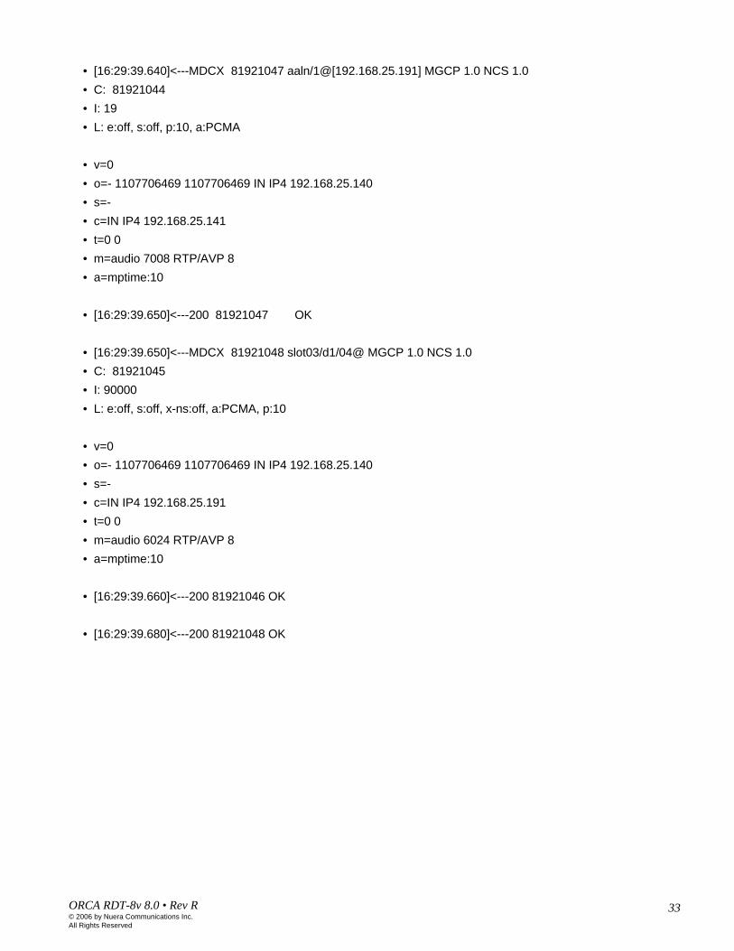
• [16:29:39.640]<---MDCX 81921047 aaln/1@[192.168.25.191] MGCP 1.0 NCS 1.0• C: 81921044• I: 19• L: e:off, s:off, p:10, a:PCMA
• v=0• o=- 1107706469 1107706469 IN IP4 192.168.25.140• s=-• c=IN IP4 192.168.25.141• t=0 0• m=audio 7008 RTP/AVP 8• a=mptime:10
• [16:29:39.650]<---200 81921047 OK
• [16:29:39.650]<---MDCX 81921048 slot03/d1/04@ MGCP 1.0 NCS 1.0• C: 81921045• I: 90000• L: e:off, s:off, x-ns:off, a:PCMA, p:10
• v=0• o=- 1107706469 1107706469 IN IP4 192.168.25.140• s=-• c=IN IP4 192.168.25.191• t=0 0• m=audio 6024 RTP/AVP 8• a=mptime:10
• [16:29:39.660]<---200 81921046 OK
• [16:29:39.680]<---200 81921048 OK

34ORCA RDT-8v 8.0 • Rev R© 2006 by Nuera Communications Inc.All Rights Reserved
34NCS
Modem Upspeed – Call Originated by IAD
PSTN: Establish (V 5.2)
PSTN: Establish Ack; (V 5.2)
BCC: Allocation (channel #, link ID); (V5.2)
LEIAD RDT CM RDT UPM
200 OK (NCS)
Off HookNotify: O:hd (NCS)
200 OK SDP1 (NCS)CRCX: sendrecv
Remote SDP1
CRCX: sendrecv, G.726, SDP2 (NCS)
200 OKBCC: Allocation Complete (V 5.2)
RQNT: R:hd (NCS)
200 OK
RQNT: R:hu, hf (NCS)
200 OK (NCS)
Notify: O:mt (NCS)
200 OKMDCX: s:off,e:off, PCMa, SDP (NCS)
MDCX:s:off,e:off, PCMa200 OK
200 OK
Dialed Digits (in band)
Modem tone (in band)
Full duplex modem call established
Dial Tone (in band)
• IAD goes off hook towards the cable modem. The cable modem generates an NCS “Notify” message towards the RDT containing the observed event and on which endpoint the event occurred.
• RDT CM sends the PSTN: Establish message indicating an originating path request. RDT informs LE of off-hook condition.• The RDT responds with a 200 OK to the previous NTFY.• RDT CM requests IAD to notify it when either an on-hook or hook-flash is detected.• IAD acknowledges the RQNT.• The LE responds with a PSTN: Establich Ack message to the previous Establish message, indicating that the requested action was
performed.• The LE sends a BCC: Allocation message. The Allocation message is sent by the LE to request the RDT to allocate a bearer (voice)
channels ( V5.2 timeslots or E1 channels within theV5.2 interface) to a user port for a call. The LE always controls allocation and de-allocation of bearer channels. The LE is responsible for correlating between the subscriber DN used by the outside world and the V5.2 user port ID used within the access network.
• The RDT CM instructs the IAD to create connection, Mode: sendreceive, vocoder rate for voice is set to G.726, 32kbps. IP addresses are statically allocated to E1 channels at the RDT. Therefore, the host implicitly knows the IP address associated with E1 channel allocated by the LE and may provide this IP address in the CRCX to the IAD. Since we want to upspeed modem rate to 64 kbs, a MDCX command is needed.
• The IAD acknowledges the CRCX command.• An internal Create connection message is sent to the UPM. • The UPM acknowledges the CRCX command.• A V 5.2 BCC: Allocation Complete message will be generated back towards the LE once the “200 OK” messages from the UPM have
been received at the CM module. This message serves as an acknowledgement that the allocation of requested bearer channels was successful.
• At this time the LE sends the in band dial tone to the IAD.• At this time, the audio path is open to receive dialed digits from the end user.• Dialed digits will be passed in-band from the IAD to the LE.• Modem tone sent by both sides.• When Modem tones are detected a MDCX is sent from the RDT CM to IAD and to UPM to turn off echo canceller and VAD and to change
data rate to PCMa.• At this point a full duplex call is established from end to end.

35ORCA RDT-8v 8.0 • Rev R© 2006 by Nuera Communications Inc.All Rights Reserved
35NCS
Failed Modem Upspeed, vocoder = G.726 32kbpsIAD RDT CM RDT UPM LE
200 OK
NTFY(O:mt)200 OK
MDCX(PCMA,s:off:e:off)
DSA RES
DSA ACK
DSA REQ
5xx Response
RQNT(r:hd)
200 OKNTFY (O:hd)
200 OK
ESTABLISH
ESTABLISH ACK
ALLOCATE(DS0)CRCX G726
200 OK (remote SDP) CRCX(remote SDP, R:mt,ft)
ALLOC ACK
MDCX(G726,s:off,e:off)
200 OK
Dial Tone (in band)
200 OKRQNT: R:hu,hf
200 OK 200 OK
MDCX200 OK
Call still at G.726
Dialed Digits (in band)
Modem tone (in band)
• Messages exchanged between the RDT CM card, UPM, Class 5 switch, and IAD when there is an incoming call are the same as in the previous call flow diagram until the moment the MDCX command is sent.
• The CM card instructs the UPM card and the IAD to modify connection and to turn silence suppression and echo cancellation off and to change the bandwidth to PCM, MDCX: PCMA, s:off, e:off.
• If the IAD, for some reason, is not able to do the requested upspeed, it may respond with a 5xx message, or it may respond with the 200 OK, and only later send a 5xx response. The response depends on the IAD. Various IADs behave differently.
• When the RDT CM card receives the 5xx response it sends a new MDCX command to the IAD and UPM instructing them to use G.726 vocoder and turn silence suppression and echo cancellation off, MDCX: G726, s:off, e:off.
36ORCA RDT-8v 8.0 • Rev R© 2006 by Nuera Communications Inc.All Rights Reserved
36NCS
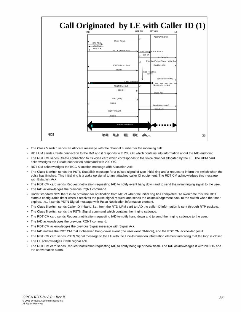
Call Originated by LE with Caller ID (1)ALLOCATE(DS0)
CRCX PCMADSA REQDSA RESDSA ACK
200 OK (remote SDP) CRCX(remote SDP, R:mt,ft)
ALLOC ACK
Caller ID inband
Establish ACKRQNT(R:hd,oc; S:rs)
200 OK
Signal (Pulse Notif.)
Initial Ring timerexpires
Signal(cadence ring)RQNT(R:hd; S:r0)
200 OKSignal Ack
200 OK
Establish (Pulsed Signal - Initial Ring)
NTFY (o:hd)
200 OKSignal (loop closed)
Signal AckRQNT (R:hu,hf)
200 OK
IAD RDT CM RDT UPM LE
Voice Conversation
• The Class 5 switch sends an Allocate message with the channel number for the incoming call .• RDT CM sends Create connection to the IAD and it responds with 200 OK which contains sdp information about the IAD endpoint.• The RDT CM sends Create connection to its voice card which corresponds to the voice channel allocated by the LE. The UPM card
acknowledges the Create connection command with 200 OK.• RDT CM acknowledges the BCC Allocation message with Allocation Ack.• The Class 5 switch sends the PSTN Establish message for a pulsed signal of type initial ring and a request to inform the switch when the
pulse has finished. This initial ring is a wake up signal to any attached caller ID equipment. The RDT CM acknowledges this message with Establish Ack.
• The RDT CM card sends Request notification requesting IAD to notify event hang down and to send the initial ringing signal to the user. • The IAD acknowledges the previous RQNT command.• Under standard NCS there is no provision for notification from IAD of when the initial ring has completed. To overcome this, the RDT
starts a configurable timer when it receives the pulse signal request and sends the acknowledgement back to the switch when the timer expires, i.e., it sends PSTN Signal message with Pulse Notification information element.
• The Class 5 switch sends Caller ID in-band, i.e., from the RTD UPM card to IAD the caller ID information is sent through RTP packets.• The Class 5 switch sends the PSTN Signal command which contains the ringing cadence.• The RDT CM card sends Request notification requesting IAD to notify hang down and to send the ringing cadence to the user. • The IAD acknowledges the previous RQNT command.• The RDT CM acknowledges the previous Signal message with Signal Ack.• The IAD notifies the RDT CM that it observed hang-down event (the user went off-hook), and the RDT CM acknowledges it.• The RDT CM card sends PSTN Signal message to the LE with the Line-Information information element indicating that the loop is closed.• The LE acknowledges it with Signal Ack.• The RDT CM card sends Request notification requesting IAD to notify hang up or hook flash. The IAD acknowledges it with 200 OK and
the conversation starts.
37ORCA RDT-8v 8.0 • Rev R© 2006 by Nuera Communications Inc.All Rights Reserved
37NCS
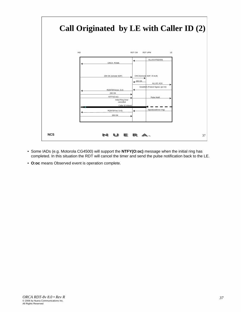
Call Originated by LE with Caller ID (2)
IAD RDT CM RDT UPM LE
200 OK
ALLOCATE(DS0)
CRCX PCMA
200 OK (remote SDP) CRCX(remote SDP, R:mt,ft)
ALLOC ACK
Establish (Pulsed Signal, (ps=ir))RQNT(R:hd,oc; S:ir)
200 OK
Pulse Notif.Initial Ring timer
cancelled
NTFY(O:oc)
Caller ID inband
Signal(cadence ring)RQNT(R:hd; S:r0)
200 OK
• Some IADs (e.g. Motorola CG4500) will support the NTFY(O:oc) message when the initial ring has completed. In this situation the RDT will cancel the timer and send the pulse notification back to the LE.
• O:oc means Observed event is operation complete.

38ORCA RDT-8v 8.0 • Rev R© 2006 by Nuera Communications Inc.All Rights Reserved
38NCS
Caller ID with Low Bit Rate VocoderALLOCATE(DS0)
CRCX PCMA
200 OK (remote SDP) CRCX(remote SDP, R:mt,ft)
ALLOC ACK
Caller ID inband
Establish ACKRQNT(R:hd,oc; S:rs)
200 OK
Signal (Pulse Notif.)
Initial Ring timerexpires
Signal(cadence ring)MDCX(G729A R:hd; S:r0)
200 OKSignal Ack
200 OK
Establish (Pulsed Signal - Initial Ring)
NTFY (o:hd)
200 OKSignal (loop closed)
Signal AckRQNT (R:hu,hf)
200 OK
IAD RDT CM RDT UPM LE
Voice Path at G729A
• The call flow diagram in the slide shows the call flow for an incoming call with caller ID downspeed enabled. The call is initially created at G711. When the cadence ring has been received from the LE the RDT knows that the caller ID sequence has finished and changes the call to G729A. An MDCX is sent to the IAD requesting a vocoder change. When the UPM senses that the incoming packet stream from the IAD has changed it will change its vocoder for transmission accordingly.
• There is no need to modify the connection parameters on the UPM as it will switch to a vocoder depending on the incoming packet type.

39ORCA RDT-8v 8.0 • Rev R© 2006 by Nuera Communications Inc.All Rights Reserved
Call WaitingCall Originated by IAD
IAD
RDTCM
RDTUPM
LE
5. 200 OK
(NCS)
Off Hook 3. Notify:
O:hd (NCS)
11. 200 OK SDP1 (NCS) 12. CRCX:
Remote SDP1
4. PSTN: Establish (V5.2)
8. PSTN: Establish Ack(V5.2)
10. CRCX: SDP2 (NCS), mode=sendrecv
13. 200
OK
14. BCC: Allocation complete (V5.2)
15. Dial Tone (in band)
16. Dialed Digits (in band)
17. Ring back (in band)
6. RQNT: R:hu, hf (NCS)
7. 200 OK (NCS)
1. RQNT: R:hd (NCS)
2. 200 OK
19. Call waiting PIP tone inserted by LE
20. Notify: O:hf (NCS)23. 200
OK (NCS)
21. Establish (Pulsed Signal – Register recall) (V5.2)
25. Notify: O:hf (NCS)
28. 200 OK
(NCS)
24. IAD user connected to second call
29. IAD user connected to first call
18. Two way voice path
9. BCC: Allocation (channel #, link ID) (V5.2)
22. PSTN: Establish Ack (V5.2)
26. Establish (Pulsed Signal – Register recall) V5.2
27. PSTN: Establish Ack (V5.2)

40ORCA RDT-8v 8.0 • Rev R© 2006 by Nuera Communications Inc.All Rights Reserved
• For call waiting feature doesn’t matter whether the call is originated by the IAD or switch.
• The call flow up to step 19 is the same as in the call originated by IAD in the first call flow diagram.
• 19. After the two-way media path is established the switch detects another call for IAD user and since the user has call waiting, the switch injects the call waiting PIP tone in the existing media path to alert the IAD user.
• 20. The IAD user presses FLASH to accept the new call and the IAD sends NTFY O: hf (observed event is hook flash) to the RDT CM. The RDT CM acknowledges the NTFY command with 23. 200 OK.
• 21. The RDT CM sends V5.2 command Establish (Pulsed Signal – Register recall) indicating to the LE side that a hook flash tone was observed on the IAD side.
• 22. The LE acknowledges the previous Establish command.
• 24. LE puts the the first connection on hold, answers the new call and connects it to the IAD using the existing media path.
• 25. The IAD user presses FLASH button to return to the first call and the IAD sends NTFY O: hf (observed event is hook flash) to the RDT CM. The RDT CM acknowledges the NTFY command with 28. 200 OK and sends the Establish (Pulsed Signal – Register recall) to the LE, and the user is connected to the first call. The LE puts the second connection on hold.
• If the first called party hangs up, the LE detects it and does nothing – the media path is still up but silent. The IAD user presses FLASH to go back to the other party and scenario in step 20 and 25 will be repeated.
• If the second called party (the party on hold) hangs up first (after step 28), the media path is unaffected by the LE. It is used by the first call which is connected. If the IAD user flashes later, there will be no party left to re-connect and the IAD user shall receive dial tone form the switch.

41ORCA RDT-8v 8.0 • Rev R© 2006 by Nuera Communications Inc.All Rights Reserved
41NCS
Call Originated by IAD and LEIAD RDT CM RDT UPM LE
4. 200 OK (NCS)
Off Hook3. Notify: O:hd (NCS)
10. 200 OK SDP1 (NCS)11. CRCX: Remote SDP1
7. PSTN: Establish Ack (V5.2)
6. PSTN: Establish (V5.2)
9. CRCX: SDP2 (NCS), mode=sendrecv
12. 200 OK
13. BCC: Allocation complete (V5.2)
1. RQNT: R:hd (NCS)2. 200 OK
Glare detected by RDT CM. The incoming call proceeds normally, the outgoing Establish msg is discarded.
Glare, Vocoder = G.711
17. Two way voice path
5. PSTN: Establish(V5.2)
8. BCC: Allocation (channel #, link ID)
14. Dial Tone (in band)
15. Dialed digits (in band)
16. Ring back (in band)
• 5. After sending 200 OK as a response to the NTFY coming from the IAD, the RDT CM sends the V5.2 PSTN: Establish message, requesting service.
• 6. The switch sends its own PSTN: Establish message to the RDT CM which causes glare.
• When glare is detected by the RDT CM, the PSTN: Establish message coming from the LE has priority and the PSTN: Establish message from the RDT CM is discarded.
• The call setup proceeds with the LE allocating resources for the call.

42ORCA RDT-8v 8.0 • Rev R© 2006 by Nuera Communications Inc.All Rights Reserved
IAD CMTS RDTCM
RDTUPM
LE
5. 200 OK (NCS)
Off Hook3. Notify: O:hd (NCS)
11. 200 OK SDP1 (NCS)12. CRCX: Remote SDP1
4. PSTN: Establish (V5.2)
8. PSTN: Establish Ack (V5.2)
10. CRCX: SDP2 (NCS), mode=sendrecv
13. 200 OK
14. Allocation complete (V5.2)
6. RQNT: R:hu (NCS)
7. 200 OK (NCS)
18. First call established end to end
1. RQNT: R:hd (NCS)
2. 200 OK
15. Dial Tone
17. Ring back
16. Dialed Digits
19. Notify: O:hf (NCS)
22. 200 OK (NCS)
20. Establish (Pulsed Signal – Register recall) (V5.2)
27. Notify: O:hf (NCS)
30. 200 OK (NCS)
28. Establish (Pulsed Signal – Register recall) (V5.2)
23. Dial Tone
24. Dialed Digits
25. Ring back
26. Second call established end to end
1st called party answers
IAD user presses FLASH to start a three-way call
LE puts the 1st
connection on hold, injects dial tone in the existing voice path
2nd called party answers
LE allocates a conference bridge and ties all parties together in a three-way call
IAD user presses FLASH to start a three-way call
IAD user dials digits to reach the 3rd
party
31. Three-way call established
Three-way Call, Vocoder = G.711Call Originated by IAD
9. BCC: Allocation (V5.2)
21. Establish Ack (V5.2)
29. Establish Ack (V5.2)
43ORCA RDT-8v 8.0 • Rev R© 2006 by Nuera Communications Inc.All Rights Reserved
IAD RDT CM RDT UPM LE
5. 200 OK (NCS)
Off Hook3. Notify: O:hd (NCS)
11. 200 OK SDP1 (NCS)12. CRCX: Remote SDP1
4. PSTN: Establish (V5.2)
8. PSTN: Establish Ack (V5.2)
10. CRCX: SDP2 (NCS), mode=sendrecv
13. 200 OK
14. BCC: Allocation complete (V5.2)
15. Dial Tone
16. Dialed Digits
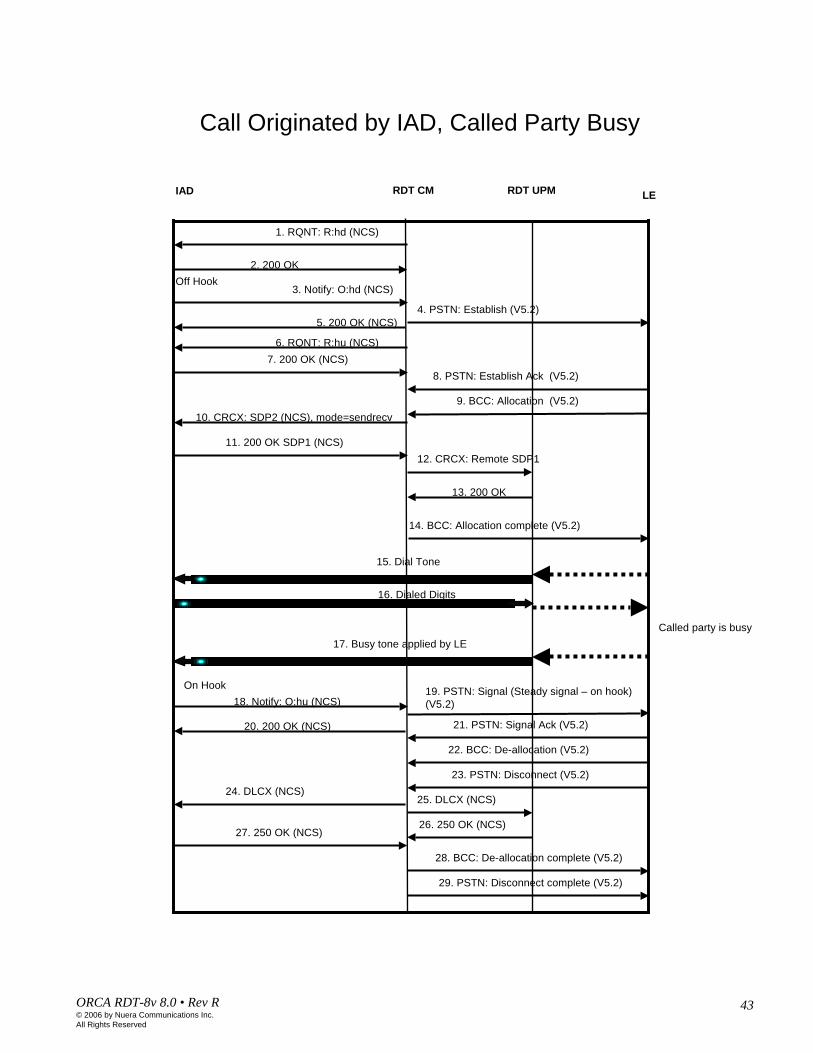
17. Busy tone applied by LE
6. RQNT: R:hu (NCS)7. 200 OK (NCS)
1. RQNT: R:hd (NCS)
2. 200 OK
18. Notify: O:hu (NCS)
20. 200 OK (NCS)
19. PSTN: Signal (Steady signal – on hook) (V5.2)
Called party is busy
On Hook
21. PSTN: Signal Ack (V5.2)
24. DLCX (NCS)25. DLCX (NCS)
26. 250 OK (NCS)27. 250 OK (NCS)
28. BCC: De-allocation complete (V5.2)
29. PSTN: Disconnect complete (V5.2)
Call Originated by IAD, Called Party Busy
9. BCC: Allocation (V5.2)
22. BCC: De-allocation (V5.2)
23. PSTN: Disconnect (V5.2)

44ORCA RDT-8v 8.0 • Rev R© 2006 by Nuera Communications Inc.All Rights Reserved
44NCS
Subscriber Added
Unblock subscriber; (V 5.2)
IAD RDT CMDNS LE
200 OK (NCS)
AUEP (F:I) *
Unblock Ack (V 5.2)
DNS Query
RQNT: R:hd (NCS)
200 OK (NCS)
In the Alarm dialog DNS Error Alarm is displayed. If the Query fails the alarm stays in the Alarm dialog. If DNS responds back:
If RDT doesn’t get a response, Communication Failure alarm is displayed and stays in the Alarm dialog. If the response is 200 OK, the exchange of Unblock and Unblock Ack messages follows and the alarm is only displayed very briefly:
If the response to this message is not received Blocked by switch alarm is displayed and stays in the Alarm dialog, otherwise
Unblock subscriber; (V 5.2)
Unblock Ack (V 5.2)
…….
* IAD RDTCM
AUEP (F:I)
200 OK (I:xxx,yyy)
DLCX
250 OK (I:xxx,yyy)
• First time when we add a subscriber to the RDT list of subscribers, or we turn the RDT on, or for some reason the communication between the subscriber and RDT fails, the following three alarms will exist:
• DNS alarm• Communication failure• Blocked by switch
• The alarms are ordered from the highest severity to the lowest. Initially all three alarms are present but the highest severity alarm is displayed only for a short time in the Alarm dialog, and as the conditions for the alarm’s existence are not present, the alarm will clear and the next alarm will be displayed. As the conditions for this alarm are not there, it will clear from the Alarm dialog, and the third alarm in the list above will be displayed, and if everything functions properly, it will clear.
• When a subscriber is added, the RDT CM sends a DNS query to the DNS server. If the query fails, “DNS Error” alarm is displayed in the Alarm dialog.
• If the query is successful, the previous alarm clears very quickly and the RDT CM sends an AUEP command to the IAD. If for any reason the command times out “Communication Failure” alarm is displayed.
• If the IAD acknowledges the AUEP command (either there are existing connections or not) with 200 OK or 250 OK, the previous alarm clears quickly and the RDT sends an Unblock subscriber command to the switch, LE. If the Unblock command times out, “Blocked by switch” alarm is displayed.
• If everything is OK in the communication between the RDT and LE, the LE responds with the Unblock Ack command.• The LE then sends an Unblock command to the RDT and RDT responds with Unblock Ack.• The RDT CM sends an RQNT (R:hd) command requesting the IAD to report when the endpoint observes that the user went
off-hook. The rest of the diagram is like previously explained call flow diagrams and depends on which side is placing the call, IAD or LE.
• * If there are connections on the endpoint, the endpoint responds to the AEUP (F:I) command with 200 OK and the list of connections’ IDs. The RDT sends a DLCX command to the IAD instructing it to delete all active connections, and the IADresponds with 250 OK. The subscriber is now in an operational, but blocked by switch, state.

45ORCA RDT-8v 8.0 • Rev R© 2006 by Nuera Communications Inc.All Rights Reserved
45NCS
Subscriber Blocked by Switch
...
Unblock
RDT CMLE
Unblock Ack
Block
Block Ack
Unblock
RDT CMLE
No response
Subscriber added to the LE list, but not enabled in the LE
Subscriber not added to the LE list
• If the subscriber is not added to the LE list, the Unblock command coming from the RDT CM is ignored, there is no response and the “Subscriber blocked by switch” alarm is displayed in the Alarm dialog.
• If the subscriber is added to the LE list, but not enabled in the switch, the Unblock command from RDT CM is responded to, but later the switch sends a Block message to the RDT.
46ORCA RDT-8v 8.0 • Rev R© 2006 by Nuera Communications Inc.All Rights Reserved
46NCS
Polling
IAD11
IAD20
...
IAD30
IAD21...
IAD10 IAD1IAD3 IAD2
...
LE
1a. RQNT
1b. OK2a. RQNT2b. OK
5 minutes
5 minutes15 minutes
E1
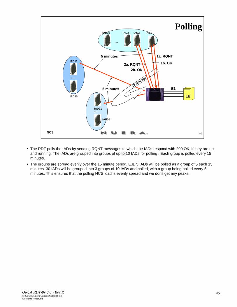
• The RDT polls the IADs by sending RQNT messages to which the IADs respond with 200 OK, if they are up and running. The IADs are grouped into groups of up to 10 IADs for polling . Each group is polled every 15 minutes.
• The groups are spread evenly over the 15 minute period. E.g. 5 IADs will be polled as a group of 5 each 15 minutes. 30 IADs will be grouped into 3 groups of 10 IADs and polled, with a group being polled every 5 minutes. This ensures that the polling NCS load is evenly spread and we don't get any peaks.

47ORCA RDT-8v 8.0 • Rev R© 2006 by Nuera Communications Inc.All Rights Reserved
47NCS
Polling – No Response
LE
DNS
IAD1
IAD1
LE
DNS
LE
DNS
1. RQNT
2. RQNT
10. RQNT
...
500 ms
11. Block IAD1
12. Look up IAD1 IP address13. IAD1 IP address
14. After 15 minutes the polling starts again
E1
E1
E1
IAD1
• Let’s assume that the IAD is operational. It is polled every 15 minutes by the RDT. If, for some reason, the RQNT polling message sent to the IAD is not responded to, the RDT keeps sending the RQNT to IADs every 500ms for 10 resends. After the 10th attempt the IAD is determined to be in a fault state and a “Subscriber communication failure" alarm is raised.
• When the IAD is considered unreachable the RDT sends a BLOCK message to the switch to block that port. • In the next step the RDT does a DNS lookup in case the IP address has changed. When the response comes
back the RDT tries the poll again. If the RDT still receives no response, 2 minutes later it will try the DNS/poll sequence again. If the RDT receives an RSIP in the meantime, then the fault state will be cleared.
• If the RDT doesn't get a DNS response, it raises a " Subscriber DNS Error" alarm and keeps sending a DNS/poll to the IAD every 2 minutes until it recovers.
• Note – the same procedure of retransmitting the NCS messages is applied if any of the NCS messages from the RDT are not responded to by the IADs.
48ORCA RDT-8v 8.0 • Rev R© 2006 by Nuera Communications Inc.All Rights Reserved
48NCS
RQNT vs AUEP Polling
IAD
1. Handshaking
IP
2. IAD is in a call
1. RSIP
RDT
2. 200 OK
3. AUEP (F:I)4. 200 OK (I:xx)
IP2. 200 OK (I:yy)
RDT
1. AEUP (F:I)
3. IAD is idle
IP2. 200 OK
RDT
1. RQNT (R: hd)
RQNT
AUEP
IAD
IAD
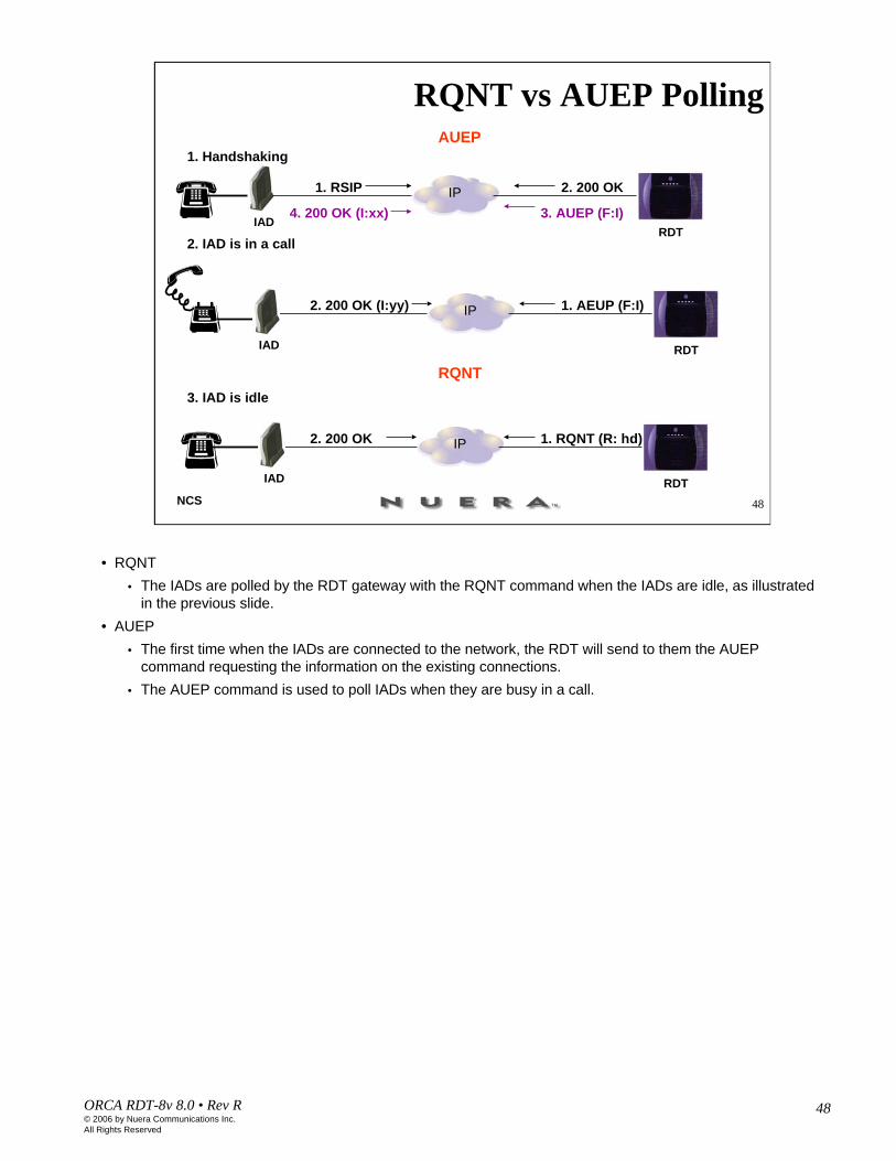
• RQNT• The IADs are polled by the RDT gateway with the RQNT command when the IADs are idle, as illustrated
in the previous slide.• AUEP
• The first time when the IADs are connected to the network, the RDT will send to them the AUEP command requesting the information on the existing connections.
• The AUEP command is used to poll IADs when they are busy in a call.