nd-4679-en - brimrun.is · nd-4679-en ku-100 operation and maintenance manual 1 ... rev. mar 2010 ....
TRANSCRIPT


ND-4679-EN KU-100 Operation and Maintenance Manual
1
KU-100 KU-BAND VSAT
Operation and Maintenance Manual
This user guide explains the fundamentals of the Ku-100 antenna system for usage, troubleshooting. For details about installation, please refer to the Ku-100 Installation Manual.
<Table of Contents> page
For safe and proper operation 2
1. System Overview 11
1.1 System Components 13
2. Initial Settings 17
2.1 Setting Preparations 18
2.1.1 Install maintenance tool 19
2.2 Setting File Preparations for ACU 23
2.2.1 Local Setting File 24
2.2.2 Alignment Setting File 26
2.2.3 Blocking Area File 28
2.2.4 Network Setting for Ku-Mate Navigator 31
2.3 Update Settings 32
3. Operation 36
4. Troubleshooting 37
4.1 Troubleshooting Overview 37
4.2 Troubleshooting 38
5. Parts Replacement 39
Glossary 40
Rev. Mar 2010

ND-4679-EN KU-100 Operation and Maintenance Manual
2
For safe and proper operation
• This manual provides information for proper operation of KU-100.
• Read this manual carefully before use.
• Keep this manual at a place for operators and maintenance personnel referring at any time to see.
• Keep Cautions for Safety and Cautions for Installation for proper operation and prevention from happening for an accident of physical injury and/or damage of property.
• Hazard Level caused by improper use is shown by . Details are defined in a table.
CAUTION!!!!!!!! WARNING

ND-4679-EN KU-100 Operation and Maintenance Manual
3
【【【【Cautions for Installation】】】】
When wrong handling is done,
there in a possibility of relating
to death or serious injury.
WARNING!!!!
PROHIBITTED
Do not install and connect every unit to outside of service technician.
It may cause fire or electric shocks.
Equipment not suitable for use in the presence of a flammable anesthetic mixture with
air or with oxygen or nitrous oxide.
It may cause fire.
Do not install ACU in humid area
It may cause fire or electric shocks.
There is an air inlet on hatch of ADU.
Do not close the inlet.
It may cause malfunction.
Do not set anything heavy on the cables connected to the unit nor allow it to become
pinched, or cut. If the power cord becomes damaged, replace it immediately to avoid
shock hazard or electrical fire.
When the power cord is replaced, use the same type as originally supplied.
Do not connect power cable to multiple outlet.
It may cause fire.

ND-4679-EN KU-100 Operation and Maintenance Manual
4
【【【【Cautions for Installation】】】】
When wrong handling is done,
there in a possibility of relating
to death or serious injury.
WARNING!!!!
FOLLOW INSTRUCTIONS
This product is designed to operate at 100-240V AC 50/60Hz.
Never connect to any outlet or power supply having a different voltage or frequency.
Excess power may cause trouble or fire.
It may cause electric shocks if not grounded.
Equipment energized from an external electrical power source, Class I equipment.
KU-100 must be earthed.
Use over AWG18 cable.
(* IEC 60335.1, IEC60598.1)
Accessory screws and nits fixate ADU absolutely to the vessel mast.
It may cause to drop or fall and result to physical injury.
Be sure to pick up ADU by the crane.
It may cause to drop or fall and result to physical injury.
The ACU is an air-cooled type. Do not block the inlet or outlet of the air route.
The inlet is located on each side and the outlet is on the rear.
Be sure daily check condition of DC fan on back side ACU.
When unplugging the power cord, hold the plug, and remove it carefully.

ND-4679-EN KU-100 Operation and Maintenance Manual
5
【【【【Cautions for Installation】】】】
When wrong handling is done,
there in a possibility of relating
to damage of injury or property.
CAUTION!!!!
PROHIBITTED
Do not install the unit in places with excessive vibration or on unstable areas.
It may cause to drop or fall and result to physical injury.
Be careful not to pull the cables connected to the unit with excess force during
plugging/unplugging or when the connecters are in use.
It may cause malfunction.
Clean up the surface of radome so as not to block the antenna.
It may cause malfunction.
Heavy objects can damage ACU and cause malfunction.
It may cause malfunction.
ND-4679-EN KU-100 Operation and Maintenance Manual
6
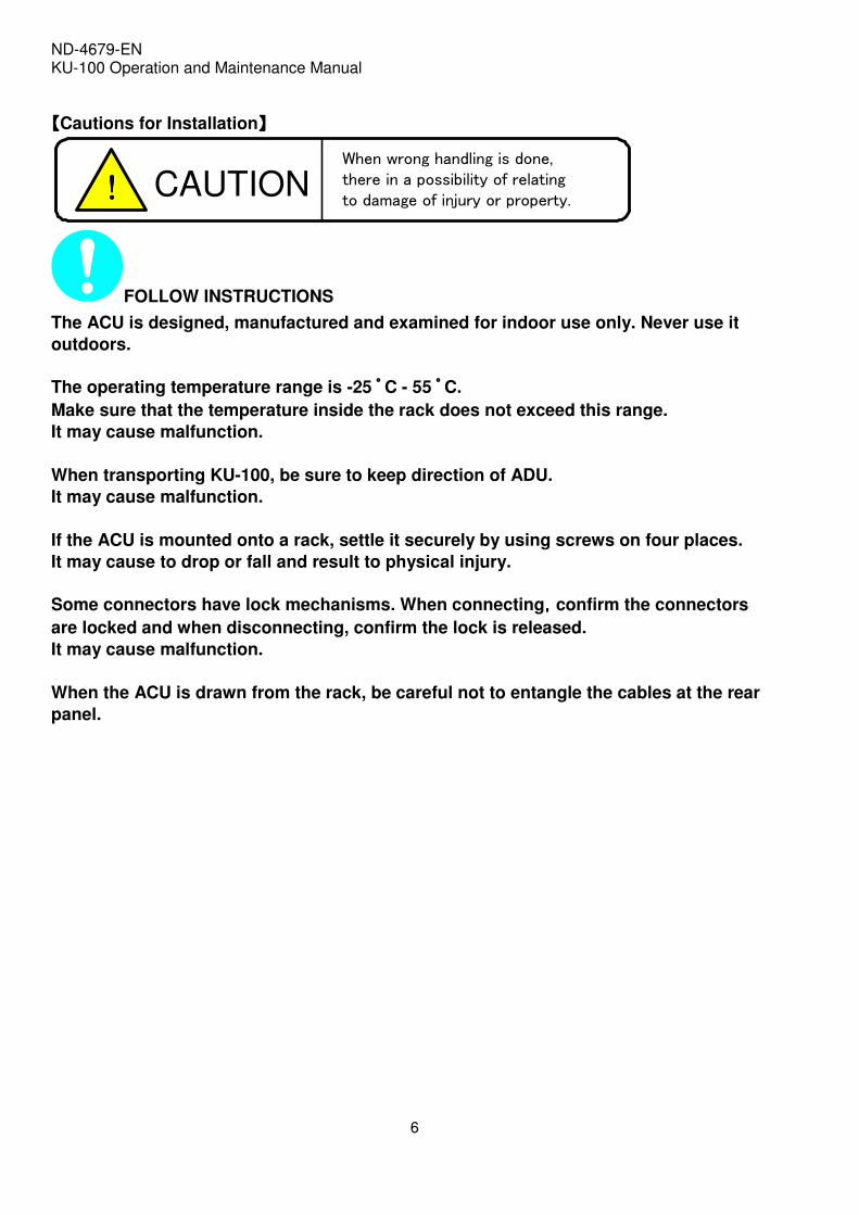
【【【【Cautions for Installation】】】】
When wrong handling is done,
there in a possibility of relating
to damage of injury or property.
CAUTION!!!!
FOLLOW INSTRUCTIONS
The ACU is designed, manufactured and examined for indoor use only. Never use it
outdoors.
The operating temperature range is -25 ゚゚゚゚ C - 55 ゚゚゚゚ C.
Make sure that the temperature inside the rack does not exceed this range.
It may cause malfunction.
When transporting KU-100, be sure to keep direction of ADU.
It may cause malfunction.
If the ACU is mounted onto a rack, settle it securely by using screws on four places.
It may cause to drop or fall and result to physical injury.
Some connectors have lock mechanisms. When connecting,,,,confirm the connectors
are locked and when disconnecting, confirm the lock is released.
It may cause malfunction.
When the ACU is drawn from the rack, be careful not to entangle the cables at the rear
panel.

ND-4679-EN KU-100 Operation and Maintenance Manual
7
【【【【Cautions for Usage】】】】
When wrong handling is done,
there in a possibility of relating
to death or serious injury.
WARNING!!!!
PROHIBITTED
Nothing other than supplies for KU-100 should ever be inserted into the ADU/ACU.
Other items can cause a safety hazard and extensive damage to the mechanism and
electronics.
Liquids which get into the unit can cause serious damage to the unit and potential
shock or fire danger. If liquid is spilled into or seeps into the unit, unplug the Power
Cord immediately and seek service as soon as possible to avoid additional or possible
damage due to corrosion.
Do not touch the ACU with a wet hand.
It may cause electric shocks.
Stay away more than 24m away from the area where the antenna may be transmitting. It
It may cause bad effects to the human body.

ND-4679-EN KU-100 Operation and Maintenance Manual
8
【【【【Cautions for Usage】】】】
When wrong handling is done,
there in a possibility of relating
to damage of injury or property.
CAUTION!!!!
PROHIBITTED
Do not repeat powering ON and OFF in a short period.
It may cause malfunction.
KU-100 is a communication system with the satellite.
Do not use another purpose.
FOLLOW INSTRUCTIONS
If clap of thunder, you must turn power off and unplug the power cord soon.
If KU-100 emits smoke or abnormal sounds, immediately unplug the power cord from
power outlet.
Contained use may be dangerous.
When do not use for a long time, unplugging the power cord.
ND-4679-EN KU-100 Operation and Maintenance Manual
9
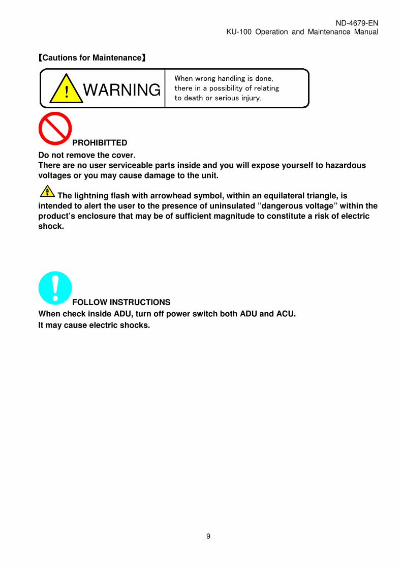
【【【【Cautions for Maintenance】】】】
When wrong handling is done,
there in a possibility of relating
to death or serious injury.
WARNING!!!!
PROHIBITTED
Do not remove the cover.
There are no user serviceable parts inside and you will expose yourself to hazardous
voltages or you may cause damage to the unit.
The lightning flash with arrowhead symbol, within an equilateral triangle, is
intended to alert the user to the presence of uninsulated ”dangerous voltage” within the
product’s enclosure that may be of sufficient magnitude to constitute a risk of electric
shock.
FOLLOW INSTRUCTIONS
When check inside ADU, turn off power switch both ADU and ACU.
It may cause electric shocks.

ND-4679-EN KU-100 Operation and Maintenance Manual
10
【【【【Cautions for Abolishment】】】】
When wrong handling is done,
there in a possibility of relating
to death or serious injury.
WARNING!!!!
FOLLOW INSTRUCTIONS
When you discard ADU and ACU, based on “Waste Disposal and Public Cleansing
Law*”, you must discard ADU and ACU as industrial waste subject to special control.
*Check the law in your home country.

ND-4679-EN KU-100 Operation and Maintenance Manual
11
1. System Overview KU-100 is an antenna system used for broadband satellite communication onboard vessel.
The KU-100 system consists of the Above Deck Unit (ADU) and Antenna Communication Unit (ACU)installed in below deck. Major performances of the KU-100 are shown in Table 1-1.
Figure1-1 KU-100 outline
ADU (Above Deck Unit) ACU (Antenna Communication Unit)

ND-4679-EN KU-100 Operation and Maintenance Manual
12
Table1-1 Major Performances of KU-100
Note- Comply with IEC60945 Eutelsat Type Approval (Cert: EA-V056)
1m Antenna
Reflector Size 1m
Radome Size Approx. 1.60m(D) x 1.75m(H)
Weight Approx. 175kg
Mount 3-axis servo control
Transmit 14.00 - 14.50 GHz / 950 - 1,450 MHz
Receive 10.95 - 12.75 GHz / 950 - 1,700 MHz
Transmit Linear
Receive Linear
Transmit >27dB
Receive >20dB
49.0dBW typ. @14.25GHz with 8W BUC
18.4dB/K typ. @12.50GHz
Method Conical Scan + Rate Sensor
Accuracy +/- 0.2 deg. (o-p)
Az 540 deg. (continuous)
El -25 to +115deg.
Average 40m / sec
Maximum 60m / sec
Roll +/-30deg/ 7sec
Pitch +/-10deg/ 5sec
Yaw +/- 4deg/ 20sec
Turning Rate +/- 6deg/sec
Vessel I/F Navigation Gyro Compass (NMEA0183)
Temperature -25 to +55 degC
Damp-Heat +40degC 93%RH 1cycle
100-240VAC 50/60Hz +/-5%Power Supply
Environmental Condition (*)
Vessel Motion
Item
Antenna
Wind Load
RF/IF Frequency
Polarization
Cross Polarization Discrimination
Tracking
Gimbal Angle Coverage
System EIRP
System G/T

ND-4679-EN KU-100 Operation and Maintenance Manual
13
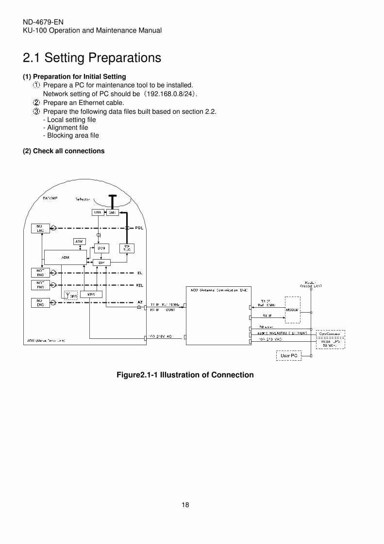
1.1 System Components The KU-100 system block diagram is shown in Figure 1.1-1. The router, GYRO compass, UPS and user PC are customer supplied equipment.
ADM 8WBUCASMReflectorRADOME POLPOLPOLPOL
ELELELELXELXELXELXELAZAZAZAZ 100-240V ACADU (Above Deck Unit)ACU (Antenna Comunication Unit)
Vessel UPS50/60HzRouter(Vessel LAN)TX IFRef 10MHzHeading NMEA0183 (HDT/HDM)MODEMRX IF100-240 VAC GyroCompassEthernet
DIPDCMLNA OMTMPS TX IF Ref 10MHzRX IF CONTGPS
User PC
MOTENCMOTENCMOTENCMOTENC
Figure1.1-1 KU-100 System Block Diagram
Table1.1-1 Abbreviation
1 ADU Above Deck Unit
2 ADM Antenna Drive Module
3 ASM Antenna Sensor Module
4 BUC Block Up Converter
5 DCM Down Converter Module
6 DIP Diplexer
7 MPS Multi Power Supply
8 MOT Motor
9 ENC Encoder
10 ACU Antenna Communication Unit
ND-4679-EN KU-100 Operation and Maintenance Manual
14
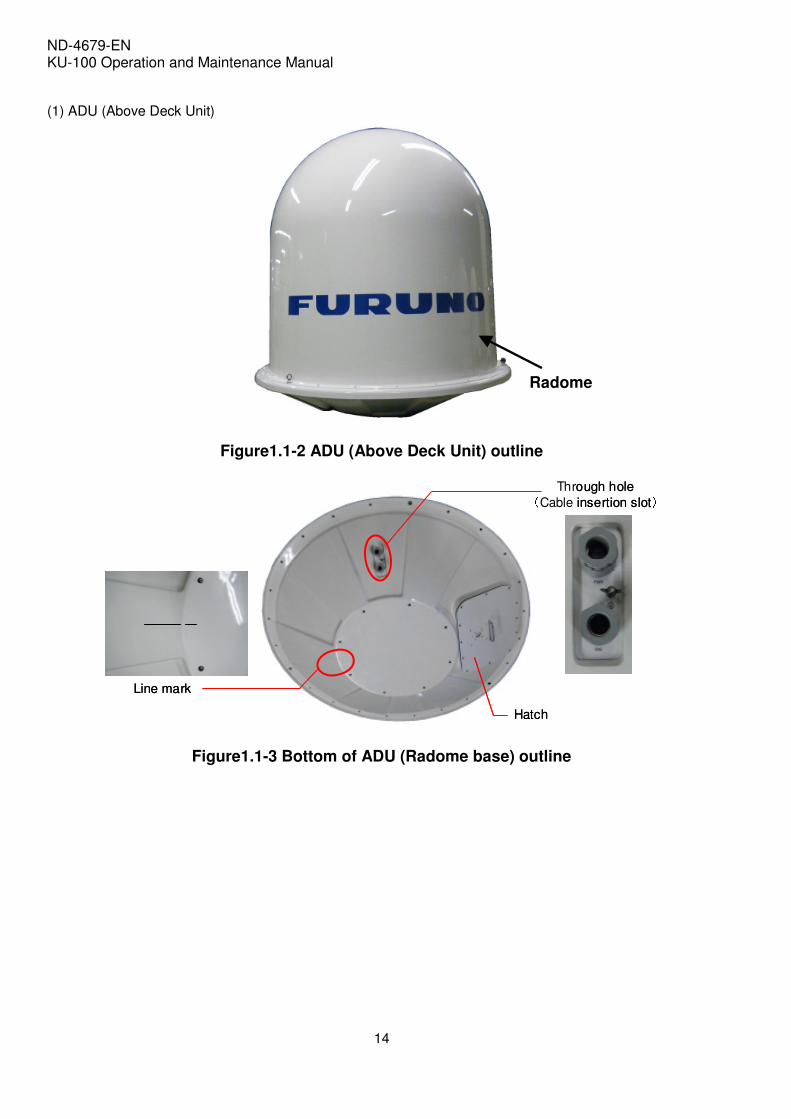
(1) ADU (Above Deck Unit)
Figure1.1-2 ADU (Above Deck Unit) outline
Through hole(Cable insertion slot)Line mark
Hatch
Through hole(Cable insertion slot)Line mark
HatchHatch
Figure1.1-3 Bottom of ADU (Radome base) outline
Radome

ND-4679-EN KU-100 Operation and Maintenance Manual
15
(2) ACU (Antenna Communication Unit) The ACU is 19-inch rack mount type.
Figure1.1-4 ACU (Antenna Communication Unit) outline
Table1.1-2 NFB Indication of Front Panel
No Indicator Description
1 POWER Non Fuse Breaker (NFB) to provide power source to ACU and ADU. Provide AC power to ACU and ACU by pulling a lever to ON.
Table1.1-3 LED Indicators
No Panel indicator Description
1 POWER (GREEN)
Show that power is provided normally.
ON : Show that power is provided and operation normally. Show the system is in normal operation. 2
OPN (GREEN)
BLINK : Include setting file is being accessed by other unit.
ON : Show the completion of satellite acquisition and the KU-100 is ready to transmit and receive signal.
3 TRKG
(GREEN) BLINK : Show the system is in the state of cessation of transmit.
4 ACU FAULT
(RED) Indicates a fault in ACU.
5 ADU FAULT
(RED) Indicates a fault in ADU.
POWER POWER OPN ACU
FAULT ADU
FAULT TRKG
NFB LED

ND-4679-EN KU-100 Operation and Maintenance Manual
16
(3) MANUAL-CD
Manual-CD contains installation manual, operation manual and maintenance tool. As shown in Figure 1.1-5.
MANUAL-CD
IM
└ KU-100 Installation Manual
OM
└ KU-100 Operation and Maintenance Manual
└KuMateNavigator_Setup.msi
Maintenance tool
MANUAL-CD
IM
└ KU-100 Installation Manual
OM
└ KU-100 Operation and Maintenance Manual
└KuMateNavigator_Setup.msi
Maintenance tool
Figure1.1-5 File tree in MANUAL-CD ①Installation manual is used when the equipment is installed to a vessel. ②Operation manual is used when you operate the KU-100. ③Maintenance tool is used when installation or maintenance work is carried out by a technician
authorized by Mitsubishi Electric Corporation. Maintenance tool includes the following software. (1) Ku-Mate Navigator : used to monitor the status of KU-100. (2) Maintain Ku-Mate : used to monitor the status of KU-100 and set various parameters during
installation or maintenance.
Ku-Mate Navigator Maintain Ku-MateKu-Mate Navigator Maintain Ku-Mate
Figure1.1-6 Screen of Ku-Mate Navigator and Maintain Ku-Mate

ND-4679-EN KU-100 Operation and Maintenance Manual
17
2. Initial Settings Initial settings are operations to install the maintenance tools to user PC, build initial setting files and transfer them to the ACU. When carrying out settings, make sure that all the necessary equipment (to the MODEM etc.) is connected. To complete the setting, satellite tracking is required. Flow chart for initial settings is shown in Figure 2-1.
Setting preparations
Install maintenance tool
Edit setting file
Update settings to ACU
Complete initial settings
Setting preparations
Install maintenance tool
Edit setting file
Update settings to ACU
Complete initial settings
Figure2-1 Flow chart for initial settings
ND-4679-EN KU-100 Operation and Maintenance Manual
18
2.1 Setting Preparations
(1) Preparation for Initial Setting ① Prepare a PC for maintenance tool to be installed.
Network setting of PC should be (192.168.0.8/24). ② Prepare an Ethernet cable. ③ Prepare the following data files built based on section 2.2. - Local setting file - Alignment file - Blocking area file
(2) Check all connections
ADM 8WBUCASMReflectorRADOME POLPOLPOLPOL
ELELELELXELXELXELXELAZAZAZAZ 100-240V ACADU (Above Deck Unit)ACU (Antenna Comunication Unit)
Vessel UPS50/60HzRouter(Vessel LAN)TX IFRef 10MHzHeading NMEA0183 (HDT/HDM)MODEMRX IF100-240 VAC GyroCompassEthernet
DIPDCMLNA OMTMPS TX IF Ref 10MHzRX IF CONTGPS
User PC
MOTENCMOTENCMOTENCMOTENC
Figure2.1-1 Illustration of Connection

ND-4679-EN KU-100 Operation and Maintenance Manual
19
2.1.1 Install maintenance tool Installation Procedure (1) Requirement for Ku-Mate Navigator
The user PC needs to have the following performance.
OS Windows XP SP3
Windows Vista SP2
CPU Pentium4 1.8GHz (Recommended 2.4GHz)
Memory 512MB min (Recommended 1GB)
HDD 50 MB min
Display 1024 × 768dot min full color
LAN With Ethernet
.NET FRAMEWORK2.0 Download from the Microsoft homepage and install to the user PC.
Language for non-Unicode programs (Recommended)
Non-Unicode program language to be selected Japanese. (Using “Regonal Language options” in the control panel.)

ND-4679-EN KU-100 Operation and Maintenance Manual
20
(2) Install ①Set CD-ROM of MANUAL-CD into CD-ROM drive. ②Double-click on the icons of “KuMateNavigator_Setup.msi” or “KuMateNavigator_Setup” in the Maintenance tool.
③After initiation of installation, click When “ update of NETFRAMEWORK”(?) appears, see the supplement of “Installation of NETFRAMWWORK2.0” This comment appears only on the PC without installation of NETFRAMEWORK2.0.
④Set the folder to be installed.
This is installed in the folder of ¥KuMate¥Navigator under C-drive by default.
⑤Select the folder in terms of user. ⑥Click

ND-4679-EN KU-100 Operation and Maintenance Manual
21
⑦Confirm the installation and click
⑧Click and complete installation.

ND-4679-EN KU-100 Operation and Maintenance Manual
22
(3)Boot up PC Ku-Mate Navigator will be started by double-clicking on the icon of Ku-Mate Navigator or Ku-Mate Navigator.exe (C:¥KuMate¥Navigator).
Short-cut for these icons will be available.
Detailed operation is described in HELP of Ku-Mate Navigator.
KuMateNavigator.exe KuMateNavigator

ND-4679-EN KU-100 Operation and Maintenance Manual
23
2.2 Setting File Preparations for ACU Setting file list explained on Table 2.2-1. Each parameter reflects from the Ku-Mate Navigator to the ACU, and becomes effective after restart.
Table2.2-1 List of Setting File (ACU) No Name Content Remarks
1 Local Setting File (localset.txt)
File for network settings of ACU.
2 Alignment Setting File (alignment.txt)
To fit coordinate axis of ADU and vessel. YAW is set to 45degrees initially.
3 Blocking Area Setting File (blocking.txt)
Setting for blocking area.
In the initial setting, all directions belong to blockage area.
Table2.2-2 List of Setting File ((((Ku-Mate Navigator))))
No Name Content Remarks
1 Setting Network (password.ini)
File for network settings of Ku-Mate Navigator.

ND-4679-EN KU-100 Operation and Maintenance Manual
24
2.2.1 Local Setting File (localset.txt) This file is for network settings. Below is an example of the local setting file. Note- If file is not set correctly, the User PC cannot connect to the ACU.
Figure2.2.1-1 Local Setting File Example
; Ku-Mate(R) SX-5300 ; antenna control unit local setting parameter file ; create date :2010/01/09 Ver 1.01 ; responsible author :Nippon Danji ; $SECURE_OPERATION_SET_START $SECURE_OPERATION_SET_END $BASIC_CONFIG_START ;======= IDENTIFY CODE SETTING =============== AcuPartsNumber ("PNRB00000-G01" ) ; AcuPartsNoInit=0 AcuSerialNumber ("SN00000000" ) ; AcuSerialNoInit=0 ;-- OPTION-------------- DisableSameTxPolAndRxPol; TxLoFreq(13.05);[GHz] ;-- INSTARATION PARAMETR -------------- setyaw ( 1 ) ;1=CW, -1=CCW setGyroDefaultReceiveSpeed(1) ;GYRO SPEED 0 = 9600, 1 = 4800 SetDdmRxGain(31);[dB] ;-- GPS-------------- ;ExGpsOn ;Ethernet GPS ExGpsOff ;Bult-in GPS ExGpsRxUdpPortNumber(10021) ;Ethernet GPS UDPport; ; ;======= NETWORK CONFIGURATION ==================== AcuMyIPaddrAndMask ("192.168.0.6",0xffffff00,40001,0x2000 ) ; ACU : IP address , subnet mask , udp receive port no, acu pin AcuLogServerIPaddress ("192.168.0.8","acu","melco123!","/home/acu") ; LoggingServer(FTP server ) IP address,ftp loginmane , ftp passwd, log dir ;I/F0 AcuSGWIPaddress ("192.168.0.7",60001, 40011,0xffff ) ; IP address,tcp port no., udp port no., pin no. ModemIPaddress ("192.168.0.7", 40012); Modem IP address, Modem Sync Status Udp port no. ;I/F1 ModemIPaddress_TCP ( "192.168.0.5", 50000);Modem IP address, Modem Tcp port no. ;MaintPC MaintPC_IPaddress ("192.168.0.8", 40021, 0xaaaa);MaintPC IP address,udp port no., pin no. setModemIfMode( 1 ) ; $BASIC_CONFIG_END
Input IP address and subnet mask (Address A)
Input IP address in the PC to store log of ACU
Input IP address of Modem (Address M)
Input IP address of a PC in which Ku-Mate Navigator is installed. (Address P)

ND-4679-EN KU-100 Operation and Maintenance Manual
25
HUB
ACUIP address:192.168.0.6Subnet mask:24bit(Address A)
PCIP address:192.168.0.8(Address P) MODEM
IP address:192.168.0.5(Address M)HUB
ACUIP address:192.168.0.6Subnet mask:24bit(Address A)
PCIP address:192.168.0.8(Address P) MODEM
IP address:192.168.0.5(Address M)
Figure2.2.1-2 Example of Network setting for connecting unit

ND-4679-EN KU-100 Operation and Maintenance Manual
26
2.2.2 Alignment Setting File (alignment.txt)
The vessel coordinate and direction of ADU line mark (Az=45°) should be in accord when setting the ADU.
To ensure accessibility to the hatch during maintenance, the ADU can be set at the position of 90/180/270°from the coordinate. In this case, input the shifted value into ”AntOffsetYaw”, shown in Figure 2.2.2-2. The Yaw direction pole is shown in Figure 2.2.2-1.
Line mark (Az=45deg)
Az=0deg
STERN BOW+++ ROLLYAWPITCHCoordinate system
Line mark (Az=45deg)
Az=0deg
STERN BOW+++ ROLLYAWPITCHCoordinate system
Figure2.2.2-1 ADU Az=45°°°°Direction and Yaw Pole
Figure2.2.2-2 Example of Alignment File
; KU-100(R) SX-5300 ; antenna control unit antenna alignment file AntAligFormatVersion ("Ver1.0") ; AntAligDataUniqName ("Ship Ant Alig") ; AntAligSettingDate ("2009/12/30 15:00:00") ; AntAligDefinitionAuthor ("Nippon Danji" ) ; AntPartsNumber ("PN000000000001" ) ; AntSerialNumber ("SN000000000001" ) ; AntMountFlag ( MOUNTED ) ; MOUNTED AntOffsetYaw ( 45.0 ) ; yaw offet[degree] AntOffsetPitch ( 0.0 ) ; 0.0 AntOffsetRoll ( 0.0 ) ; 0.0 setPolCompenRefElevation(60.0);
Input difference between Azimuth and BOW direction. In case that the line mark on radome base plate fits The direction of BOW, input 45.0.

ND-4679-EN KU-100 Operation and Maintenance Manual
27
Example In case that the direction of vessel’s bow is different from the line mark by 180degrees as shown in Figure 2.2.2-3, input 225.0 to ”AntOffsetYaw”.
Line Mark
ROLL
YAW
PITCH
Mast
ADU
BOW
Coordinate of vessel(From side view)
Line Mark
ROLL
YAW
PITCH
Mast
ADU
BOW
Coordinate of vessel(From side view)
Figure2.2.2-3 Example of ADU installation

ND-4679-EN KU-100 Operation and Maintenance Manual
28
2.2.3 Blocking Area File (blocking.txt) This is a file that specifies the vessel structure and/or blocking area. It is possible to set by every one-degree either in Elevation (-25 to 89 deg) or Azimuth (0 to 359deg) directions. Files are created according to the measurements made during equipment set up. File examples shown on Figure 2.2.3-1 to 2.2.3-3. Write the Azimuth direction on the vertical axis and the Elevation direction on the horizontal axis, ”B”(Block) in the covered direction, and ”O”(Open) in the uncovered direction.
Note- That all values are set to ”B” initially..
The file must be transferred to the ACU after the alignment adjustment has been completed. Incorrect operation may cause transmission to wrong target.

ND-4679-EN KU-100 Operation and Maintenance Manual
29
-25deg
Block area
Open area
Block area
5deg
Figure2.2.3-1 Blocking Area (Elevation Direction)
Block area
Open area
210deg
80deg
Figure2.2.3-2 Blocking Area (Azimuth Direction)

ND-4679-EN KU-100 Operation and Maintenance Manual
30
Figure2.2.3-3 Blocking Area File Example
$BLOCKING_HEAD_START BlockingDataVersion (" 1.0 ") BlockingDataUniqName("DEFAULT ") BlockingDefinitionData("2009/12/28 12:00:00 ") BlockingDefinitionAuthor(" Nippon Danji ") $BLOCKING_HEAD_END ; $BLOCKING_BODY_START ;azimuth/elevation ;-----2222221111111111000000000000000000011111111112222222222333333333344444444445555555555666666666677777777778888888888 ;-----5432109876543210987654321012345678901234567890123456789012345678901234567890123456789012345678901234567890123456789 @000,"OOOOOOOOOOOOOOOOOOOOOOOOOOOOOOOOOOOOOOOOOOOOOOOOOOOOOOOOOOOOOOOOOOOOOOOOOOOOOOOOOOOOOOOOOOOOOOOOOOOOOOOOOOOOOOOOOOO" @001,"OOOOOOOOOOOOOOOOOOOOOOOOOOOOOOOOOOOOOOOOOOOOOOOOOOOOOOOOOOOOOOOOOOOOOOOOOOOOOOOOOOOOOOOOOOOOOOOOOOOOOOOOOOOOOOOOOOO" @002,"OOOOOOOOOOOOOOOOOOOOOOOOOOOOOOOOOOOOOOOOOOOOOOOOOOOOOOOOOOOOOOOOOOOOOOOOOOOOOOOOOOOOOOOOOOOOOOOOOOOOOOOOOOOOOOOOOOO" @003,"OOOOOOOOOOOOOOOOOOOOOOOOOOOOOOOOOOOOOOOOOOOOOOOOOOOOOOOOOOOOOOOOOOOOOOOOOOOOOOOOOOOOOOOOOOOOOOOOOOOOOOOOOOOOOOOOOOO" @004,"OOOOOOOOOOOOOOOOOOOOOOOOOOOOOOOOOOOOOOOOOOOOOOOOOOOOOOOOOOOOOOOOOOOOOOOOOOOOOOOOOOOOOOOOOOOOOOOOOOOOOOOOOOOOOOOOOOO" @005,"OOOOOOOOOOOOOOOOOOOOOOOOOOOOOOOOOOOOOOOOOOOOOOOOOOOOOOOOOOOOOOOOOOOOOOOOOOOOOOOOOOOOOOOOOOOOOOOOOOOOOOOOOOOOOOOOOOO" : : : @078,"OOOOOOOOOOOOOOOOOOOOOOOOOOOOOOOOOOOOOOOOOOOOOOOOOOOOOOOOOOOOOOOOOOOOOOOOOOOOOOOOOOOOOOOOOOOOOOOOOOOOOOOOOOOOOOOOOOO" @079,"OOOOOOOOOOOOOOOOOOOOOOOOOOOOOOOOOOOOOOOOOOOOOOOOOOOOOOOOOOOOOOOOOOOOOOOOOOOOOOOOOOOOOOOOOOOOOOOOOOOOOOOOOOOOOOOOOOO" @080,"BBBBBBBBBBBBBBBBBBBBBBBBBBBBBBBOOOOOOOOOOOOOOOOOOOOOOOOOOOOOOOOOOOOOOOOOOOOOOOOOOOOOOOOOOOOOOOOOOOOOOOOOOOOOOOOOOOO" @081,"BBBBBBBBBBBBBBBBBBBBBBBBBBBBBBBOOOOOOOOOOOOOOOOOOOOOOOOOOOOOOOOOOOOOOOOOOOOOOOOOOOOOOOOOOOOOOOOOOOOOOOOOOOOOOOOOOOO" @082,"BBBBBBBBBBBBBBBBBBBBBBBBBBBBBBBOOOOOOOOOOOOOOOOOOOOOOOOOOOOOOOOOOOOOOOOOOOOOOOOOOOOOOOOOOOOOOOOOOOOOOOOOOOOOOOOOOOO" @083,"BBBBBBBBBBBBBBBBBBBBBBBBBBBBBBBOOOOOOOOOOOOOOOOOOOOOOOOOOOOOOOOOOOOOOOOOOOOOOOOOOOOOOOOOOOOOOOOOOOOOOOOOOOOOOOOOOOO" : : :
@208,"BBBBBBBBBBBBBBBBBBBBBBBBBBBBBBBOOOOOOOOOOOOOOOOOOOOOOOOOOOOOOOOOOOOOOOOOOOOOOOOOOOOOOOOOOOOOOOOOOOOOOOOOOOOOOOOOOOO" @209,"BBBBBBBBBBBBBBBBBBBBBBBBBBBBBBBOOOOOOOOOOOOOOOOOOOOOOOOOOOOOOOOOOOOOOOOOOOOOOOOOOOOOOOOOOOOOOOOOOOOOOOOOOOOOOOOOOOO" @210,"BBBBBBBBBBBBBBBBBBBBBBBBBBBBBBBOOOOOOOOOOOOOOOOOOOOOOOOOOOOOOOOOOOOOOOOOOOOOOOOOOOOOOOOOOOOOOOOOOOOOOOOOOOOOOOOOOOO" @211,"OOOOOOOOOOOOOOOOOOOOOOOOOOOOOOOOOOOOOOOOOOOOOOOOOOOOOOOOOOOOOOOOOOOOOOOOOOOOOOOOOOOOOOOOOOOOOOOOOOOOOOOOOOOOOOOOOOO" @212,"OOOOOOOOOOOOOOOOOOOOOOOOOOOOOOOOOOOOOOOOOOOOOOOOOOOOOOOOOOOOOOOOOOOOOOOOOOOOOOOOOOOOOOOOOOOOOOOOOOOOOOOOOOOOOOOOOOO" @213,"OOOOOOOOOOOOOOOOOOOOOOOOOOOOOOOOOOOOOOOOOOOOOOOOOOOOOOOOOOOOOOOOOOOOOOOOOOOOOOOOOOOOOOOOOOOOOOOOOOOOOOOOOOOOOOOOOOO" : : : @351,"OOOOOOOOOOOOOOOOOOOOOOOOOOOOOOOOOOOOOOOOOOOOOOOOOOOOOOOOOOOOOOOOOOOOOOOOOOOOOOOOOOOOOOOOOOOOOOOOOOOOOOOOOOOOOOOOOOO" @352,"OOOOOOOOOOOOOOOOOOOOOOOOOOOOOOOOOOOOOOOOOOOOOOOOOOOOOOOOOOOOOOOOOOOOOOOOOOOOOOOOOOOOOOOOOOOOOOOOOOOOOOOOOOOOOOOOOOO" @353,"OOOOOOOOOOOOOOOOOOOOOOOOOOOOOOOOOOOOOOOOOOOOOOOOOOOOOOOOOOOOOOOOOOOOOOOOOOOOOOOOOOOOOOOOOOOOOOOOOOOOOOOOOOOOOOOOOOO" @354,"OOOOOOOOOOOOOOOOOOOOOOOOOOOOOOOOOOOOOOOOOOOOOOOOOOOOOOOOOOOOOOOOOOOOOOOOOOOOOOOOOOOOOOOOOOOOOOOOOOOOOOOOOOOOOOOOOOO" @355,"OOOOOOOOOOOOOOOOOOOOOOOOOOOOOOOOOOOOOOOOOOOOOOOOOOOOOOOOOOOOOOOOOOOOOOOOOOOOOOOOOOOOOOOOOOOOOOOOOOOOOOOOOOOOOOOOOOO" @356,"OOOOOOOOOOOOOOOOOOOOOOOOOOOOOOOOOOOOOOOOOOOOOOOOOOOOOOOOOOOOOOOOOOOOOOOOOOOOOOOOOOOOOOOOOOOOOOOOOOOOOOOOOOOOOOOOOOO" @357,"OOOOOOOOOOOOOOOOOOOOOOOOOOOOOOOOOOOOOOOOOOOOOOOOOOOOOOOOOOOOOOOOOOOOOOOOOOOOOOOOOOOOOOOOOOOOOOOOOOOOOOOOOOOOOOOOOOO" @358,"OOOOOOOOOOOOOOOOOOOOOOOOOOOOOOOOOOOOOOOOOOOOOOOOOOOOOOOOOOOOOOOOOOOOOOOOOOOOOOOOOOOOOOOOOOOOOOOOOOOOOOOOOOOOOOOOOOO" @359,"OOOOOOOOOOOOOOOOOOOOOOOOOOOOOOOOOOOOOOOOOOOOOOOOOOOOOOOOOOOOOOOOOOOOOOOOOOOOOOOOOOOOOOOOOOOOOOOOOOOOOOOOOOOOOOOOOOO" $BLOCKING_BODY_END
Azimuth = 0deg Elevation = +5deg

ND-4679-EN KU-100 Operation and Maintenance Manual
31
2.2.4 Network Setting for Ku-Mate Navigator (password.ini)
This file is for network settings to use Ku-Mate Navigator Below is an example of the network setting file.
Figure2.2.4-1 Network Setting File Example
[ApplicationLogin] ApplicationAdminLoginPassword =2>012<2<012>24100<241;68 ApplicationAdminLoginCryptKey =etaMuK ApplicationGuestLoginPassword =79457=59445677435743441; ApplicationGuestLoginCryptKey =20080306 [TelnetLogin] TelnetLoginAccount =061<391201072817050023 TelnetLoginAccountCryptKey =Mitsubishi TelnetLoginPassword =2>1928020017280708050;40 TelnetLoginPasswordCryptKey=electric TelnetLoginIPAddress = 192.168.0.6 TelnetTimeOut = 10 UDPPort = 40021 [MogiServer] MogiServerHost=127.0.0.1 MogiServerPort=40005 [HealthCheckModemStatus] HMStatusUDPPort = 40006 [ForwardingService] NumberOfTargets= 1 Target_1= Disable Target_1_Address= 192.168.0.10 Target_1_Port= 40030
Input IP address of ACU (Address A)

ND-4679-EN KU-100 Operation and Maintenance Manual
32
2.3 Update Settings
Updating the prepared files are shown here. 1
Push up the ACU NFB (No Fuse Breaker) and turn on the power.
2
Confirm the POWER LED is turned on.
3
Launch Ku-Mate Navigator. IP: 192.168.0.8/24
4
Boot up Maintain Ku-Mate of Ku-Mate Navigator and update the setting file. Login Maintain Ku-Mate.
5
Select the file among “Update Config” of “tool” in “Menu” to be updated. Example show the procedure for localset and alignment file.
KuMateNavigator.exe

ND-4679-EN KU-100 Operation and Maintenance Manual
33
6
The name of the file can be changed on the screen. On completion of update of the file, Press ”Save to ACU” of “File” in the menu bar.
7
This comment shows completion of update. Press All files described in 2.2 must be updated following the steps from 5 to 7.
8
After completion of update of all files, Press down the NFB of ACU for power-off. Set network parameter of connecting unit (PC and Modem).
9
Next, push up the ACU NFB and turn on the power. Confirm the POWER LED, OPN LED, TRKG LED is turned on.
10
Start up the external equipment (MODEM/SERVER etc.) and complete the specified satellite tracking movement.
11
Boot up Maintain Ku-Mate of Ku-Mate Navigator and Adjust alignment. Login Maintain Ku-Mate.

ND-4679-EN KU-100 Operation and Maintenance Manual
34
12
Press “Start” button in the lower and center portion of screen when the system is ready for acquisition of satellite.
13
After 20 seconds, the calculation results will appear. Press “Update to ACU” button after appearance of calculated results and “OK” on the screen.
14
Push down the ACU NFB and cut off the power.
15
Next, push up the ACU NFB and turn on the power. Confirm the POWER LED, OPN LED, TRK LED is turned on.
16
Up-load blocking file to ACU. Boot Maintain Ku-Mate of Ku-Mate Navigator and login Maintain Ku-Mate.

ND-4679-EN KU-100 Operation and Maintenance Manual
35
17
Select blockingarea file among ”Update Config” of “tool” in menu bar.
18
File can be changed on the screen. On completion of update of the file, press ”Save to ACU” of “File” in the menu bar. Update in ACU will start.
19
This comment shows completion of update. Press
20
Press down the ACU NFB for power-off

ND-4679-EN KU-100 Operation and Maintenance Manual
36
3. Operation
After all setup procedures described in the previous section are done, perform the following procedure to
operate the KU-100.
Indications necessary for operation are displayed on front panel of the ACU as shown in Table 1.1-2, 1.1-3. Operation procedure on the front panel of the ACU (1) NFB (No Fuse Breaker): ADU ON
Turn NFB for ADU Power supply ON.
(2) NFB:ACU ON Wait 10 sec after Procedure (1), then turn NFB:ACU ON. Confirm that “POWER” on LED Display lights up green. If LED is turned off, be sure to check AC Power is supplied. Then all Powers turns off once and connect again. Starts from the procedure (1) again after assure to connect.
(3) Confirm that “OPERATION” on LED Display lights up green, which shows antenna is ready for
tracking. (4) Confirm green LED of “TRKG” is on. It may take some time until “TRKG” becomes ON from
“OPN” ON The state of green LED of “TRKG” being ON means that the KU-100 is under tracking.
(5) Confirm that red LEDs of “ACU FAULT” and ”ADU AULT” are OFF.
With that, It is ready for operation now.

ND-4679-EN KU-100 Operation and Maintenance Manual
37
4. Troubleshooting 4.1 Troubleshooting Overview
This section shows the common operational issues that can affect performance of the KU-100.
▦▦▦▦ Satellite Coverage Issue KU-100 accesses Geostationary satellite. KU-100 is not available in the area where transmission is unauthorized.
▦▦▦▦ Satellite Signal Blocked Anything that stands between the antenna and the satellite can block the signal, resulting in lost reception. Common causes of blockage include trees, buildings, and bridges. Heavy rain, ice, or snow might also temporarily interrupt satellite signals.
▦▦▦▦ Radar Interference KU-100 must be kept out of line with nearby radars, as their energy levels might overload the antenna’s front -end circuits. Refer to the KU-100 Installation Guide for details. KU-100 cannot catch data from Satellite.
▦▦▦▦ Loose Connectors We recommend periodical checking the antenna unit’s cable connectors in the ADU.
▦▦▦▦ Cable Unwrap If your vessel makes consecutive circles in the same direction, the antenna will rotate 360 degrees before reaching the end of its internal cable. If this occurs, the system will automatically unwrap the cable by quickly rotating the antenna dish in the opposite direction. During this time, KU-100 will freeze momentarily.

ND-4679-EN KU-100 Operation and Maintenance Manual
38
4.2 Troubleshooting Methods of treatment for various kind of malfunctions are shown in this section. The state of the KU-100 is all shown on the LED on the front panel of the ACU. It is possible to confirm the state of the unit, and any kind of trouble, by looking at the LED.
Table4.2-1 Table of Troubleshooting Methods number content of failure state of ACU front LED Method 1 cannot power on no “POWER” (Green
LED) lights Check the power cable and confirm the power is flowing normally.
100~~~~240VAC 50/60Hz
no “OPN” (Green LED) lights
Initial boot up is failed. After checking the connected equipment, resume the power. If not restored, change the ACU.
“ACU” and ”ADU” (Red LED) lights
Check the state on the screen of Ku-Mate Navigator.
2 cannot establish communication
““““TRKG””””(Green LED) blinking
The KU-100 disables to transmit because of the command from external equipment. Check the state of external equipment.

ND-3723-EN KU-100 Operation and Maintenance Manual
39
5. Parts Replacement The parts numbers for replacement can be serviced in the field are listed in Table 5-1.
Table5-1 Replaceable Units
ITEM Part Number
ADU KU-100AT/SX-5030
ADM RB154549
ASM RB256569
GPS RB363797
MPS RB363795
MOTOR-AZ RB363796
MOTOR-XEL RB363798
MOTOR-EL RB363799
MOTOR-POL RB256625
DIP RB154572
BUC RB363793
DCM RB154571
LNA RB255882
Belt-AZ RB154567-25
Belt-xEL RB154567-24
Belt-EL RB154567-23
Isolator RB154569-37
FILTER BOX* RB363825
SEMIRIDGED CABLE CBL_SM(A)
RADOME RSAK-N7821-G05
RADOME BASE RB154753
ACU KU-100AC/HS-4030 ACU
CABLE-AC NR-VM0307-VM0303-2M
*Replace FILTER BOX by new one every 3 years.

ND-4679-EN KU-100 Operation and Maintenance Manual
40
Glossary
1 ACU Antenna Communication Unit
To have the function of all states transition control in KU-100 system with communication
to modem.
To have the additional function to control the tracking system.
2 ADU Above Deck unit
3 ADM Antenna Drive Module
ADM drive and control the antenna in a coordinated manner based on the motion
information from ASM.
4 ASM Antenna Sensor Module
To have acceleration sensor, angle velocity sensor built-in, and output the sensor
information to ADM with a serial data format.
5 BUC Block Up Converter
To convert IF 1GHz signal into RF 14GHz signal and amplify RF signal up to 8W.
6 DCM Down Convertor Module
To convert RF 12GHz band signal from LNA into 2nd IF 4GHz band signal to provide with
DIP.
7 DIP Diplexer
functions
To pass on the signal between ACU and ADU.
To receive 10MHz reference signal, IF transmit band signal, base band signal from ACU.
To transmit 2nd IF receive band signal, base band signal from ACU.
To provide +24V DC power supply, 10MHz reference and IF transmit band signal to BUC.
To relay the base band signal to ADM.
To relay IF receive band signal and 10MHz reference signal to DCM.
8 MPS Multi Power Supply
To convert 100V AC power into +48V/+12V/+6.6V/+5V DC power and provide them to
other unit.
9 MOT/ENC Motor and Encoder
To drive the motors in accordance with the command from ADM.

The paper used in this manualis elemental chlorine free.
・FURUNO Authorized Distributor/Dealer
9-52 Ashihara-cho,Nishinomiya, 662-8580, JAPAN
Telephone : +81-(0)798-65-2111Fax : +81-(0)798-65-4200
A : FEB 2010.Printed in JapanAll rights reserved.
Pub. No. OME-50970-A
*00017336610**00017336610*(TATA ) KU-100*00017336610**00017336610** 0 0 0 1 7 3 3 6 6 1 0 *