ndarugu 1 water supply project bid document 1 dam water supply project bid document.pdf1. tanathi...
TRANSCRIPT

REPUBLIC OF KENYA
MINISTRY OF WATER AND IRRIGATION
STATE DEPARTMENT OF WATER
TANATHI WATER SERVICES BOARD
FUNDING DESIGN AND BUILD OF NDARUGU 1 DAM WATER
SUPPLY PROJECT
B I D D I N G D O C U M E N T S
Tender No.:TAWSB/014/2017-18
DATE: OCTOBER, 2017
EMPLOYER: The Chief Executive Officer,
Tanathi Water Services Board
KIDP Building, Kalawa Rd,
P.O Box Private Bag
KITUI KENYA
Tel: +254712351104
Email: [email protected]

Page 2 of 300
Table of Contents
Invitation for Bids .................................................................................................................................... 3
Table of Clauses ...................................................................................................................................... 6
Section 1. Instructions to Bidders ............................................................................................................. 7
A. General .......................................................................................................................................... 7
B. Bidding Documents ................................................................................................................... 11
C. Preparation of Bids .................................................................................................................... 12
D. Submission of Bids .................................................................................................................... 16
E. Opening and Evaluation of Technical Proposal .................................................................... 17
F. Opening and Evaluation of Price Proposals .......................................................................... 18
G. Award of Contract ...................................................................................................................... 20
� Bidding Documents ................................................................................................................... 23
� Preparation of Bids .................................................................................................................... 24
� Submission of Bids .................................................................................................................... 24
� Opening and Evaluation of Technical Proposal .................................................................... 25
� Opening and Evaluation of Price Proposals .......................................................................... 30
� Award of Contract ...................................................................................................................... 31
Section 2. Part I – General Conditions of Contract .................................................................................. 33
Section 3. Part II –Conditions of Particular Application ............................................................. 35
Section 4. Employer’s Requirements ...................................................................................................... 46
Ndarugu 1 Dam Water Scheme ......................................................................................................... 47
Introduction ......................................................................................................................................... 47
Dam Characteristics ............................................................................................................................. 48
Raw Water Transmission ..................................................................................................................... 49
Water Treatment ................................................................................................................................. 50
Treated Water Transmission ............................................................................................................... 50
Section 5. Technical Specifications ......................................................................................................... 56
Section 6. Forms of Bid and Appendices to Bid .................................................................................... 230
Form of Technical Proposal ................................................................................................................ 231
Form of Price Proposal ....................................................................................................................... 235
Section 7. Sample Forms ...................................................................................................................... 240
Form of Bid Security (Bank Guarantee) .............................................................................................. 241
Form of Contract Agreement ............................................................................................................. 242
Form of Performance Security............................................................................................................ 244
Form of Advance Payment Security ................................................................................................... 245
Section 8. Schedules ............................................................................................................................ 246
A. SCHEDULES OF PRICES ................................................................................................................ 247
UNITS OF MEASUREMENTS ................................................................................................................ 247
B. SCHEDULE OF PAYMENT CERTIFICATE ....................................................................................... 288
Grand Summary .................................................................................................................................. 289
C. SCHEDULE OF COEFFICIENT AND INDICES FOR PRICE ADJUSTMENT ......................................... 290
D. SCHEDULE OF MAJOR ITEMS OF CONSTRUCTIONAL PLANT ...................................................... 291
E. SCHEDULE OF KEY PERSONNEL .................................................................................................. 292
F. SCHEDULE OF SUBCONTRACTORS .............................................................................................. 298
Section 9. Drawings ............................................................................................................................. 299

Page 3 of 300
Invitation for Bids

Page 4 of 300
INVITATION FOR BIDS
Tender No.: TAWSB/014/2017-18 1. Tanathi Water Services Board ('the Employer") invites sealed bids from eligible
bidders for funding, design and build and completion of Ndarugu 1 dam water supply project ("the Works") comprising of a Dam and water supply infrastructure.
2. Bidders may acquire the bidding documents, at:
Tanathi Water Services Board K.I.D.P. Building, Kalawa Road P.O. Box Private Bag Kitui Tel: 0712351104 Email: [email protected]
3. A complete set of bidding documents may be purchased by interested eligible bidders
upon payment of a nonrefundable fee of KES 1,000 (One Thousand) or equivalent convertible currency.
4. All bids must be accompanied by a Bid Security of at least 1% of the contract price,
on or before 12.00 hrs. (Local time) on 28TH
November, 2017 and must be delivered to:
The Chief Executive Officer Tanathi Water Services Board K.I.D.P. Building, Kalawa Road P.O. Box Private Bag Kitui Tel: 0712351104 Email: [email protected]
5. Completed tender documents shall be submitted in plain sealed envelopes with the
inner and outer envelopes clearly marked with the following identification:
• Bid for Funding Design and Build of Ndarugu 1 dam water supply project
• Bid Reference Number: TAWSB/014/2017-18
• DO NOT OPEN BEFORE: 28th
November, 2017 ; 12.00 Hrs East African Time

Section 1 – Instructions to bidders
Page 5 of 300
SECTION 1
INSTRUCTIONS TO BIDDERS

Section 1 – Instructions to bidders
Page 6 of 300
Section 1 - Instruction to Bidders
Table of Clauses
A. General
1. Scope of Bid 2. Public Entities Related to
Bidding Documents & to challenge & appeal.
3. Corrupt or Fraudulent Practices
4. Eligible Bidders 5. Eligible Materials, Equipment
and Services 6. Qualification of the Bidder 7. One Bid per Bidder 8. Cost of Bidding 9. Site Visit
B. Bidding Documents
10. Content of Bidding Documents
11. Clarification of Bidding Documents
12. Amendment of Bidding Documents
C. Preparation of Bids
13. Language of Bid 14. Documents Comprising the
Bid 15. Bid Form and Price
Schedules 16. Bid Prices 17. Currencies of Bid and
Payment 18. Bid Validity 19. Bid Security 20. Alternative Proposals by
Bidders 21. Pre-Bid Meeting 22. Format and Signing of Bid
D. Submission of Bids
23. Sealing and Marking of Bids 24. Deadline for Submission of
Bids 25. Late Bids 26. Modification and Withdrawal
of Bids
E. Opening and Evaluation of
Technical Proposals
27. Opening of Technical bids 28. Process to be Confidential 29. Clarification of Technical
Proposals 30. Preliminary Examination of
Technical Proposals 31. Evaluation and Comparison
of Technical Proposals 32. Invitation to Attend Opening
of Price Proposals F. Opening of Price Proposals
33. Bid Opening of Price Proposals
34. Proposals to be Confidential 35. Clarification of Price
Proposals 36. Preliminary examination of
bids and determination of responsiveness
37. Correction of Errors 38. Conversion to Single
Currencies 39. Evaluation and Comparison
of Price Proposals 40. Margin of Preference
G. Award of Contract
41. Award 42. Employer’s Right to Accept
any Bid and to Reject any of all Bids
43. Notification of Award 44. Signing of Contract 45. Performance Security 46. Advance Payment
H. Sourcing of Funds
47. Source of Funds

Section 1 – Instructions to bidders
Page 7 of 300
Section 1. Instructions to Bidders
A. General
1. Scope of Bid 1.1 The Employer indicated in the Bid Data Sheet (BDS) wishes to receive bids for funding, design and build and completion of works as specified in the Bid Data Sheet, and Employer’s Requirements. Brief particulars of the Project are as indicated in the Bid Data Sheet.
1.2 The successful bidder will be expected to complete the Works within the time specified in the Bid Data Sheet.
2. Review of Procurement Decisions
2.1
A Bidder who claims to have suffered or risk suffering, loss or damage or injury as a result of breach of a duty imposed on an Employer or an Approving Authority by the Public Procurement and Disposal Act, 2015 and the Public Procurement and Disposal Regulations 2015, the procurement proceedings or processes, may seek administrative review as prescribed by the Act. The following matters, however, shall not be subject to the administrative review:
(a) The choice of procurement method;
(b) a decision by the Employer to reject all Tenders, proposals or quotations;
(c) Where a contract is signed in accordance to Section 68 of the Public Procurement and Disposal Act,2005;
(d) Where an appeal is frivolous. 2.2 The Bidder shall submit an application for review in the number of
copies and pay fees as prescribed by the Public Procurement and Disposal Regulations 2015 within fourteen (14) days of the time the Bidder became or should have become aware of the circumstances giving rise to the complaint or dispute.
2.3 Any application for administrative review shall be submitted in writing to the Secretary, Public Procurement Administrative Review Board on Form RB1 at the address shown in the Bid Data Sheet. The secretary to the review board shall immediately after filing of the request, serve a copy thereof on the Employer or Director-General as the case may be.
2.4 The application for administrative review shall be in accordance with the requirements of the Public Procurement and Disposals Regulations , including:
a) Reasons for the complaint, including any alleged breach of the Act or Regulations;
b) An explanation of how the provisions of the Act and or Regulation has been breached or omitted, including the dates and name of the responsible public officer, where known;
c) Statements or other evidence supporting the complaint where available as the applicant considers necessary in support of its request;
d) Remedies sought; e) Any other information relevant to the complaint.
2.5 The Administrative Review Board shall within thirty days after receipt of an application for administrative review deliver a written decision which shall indicate:
a) Annulling anything the Employer has done in the procurement proceedings, including annulling the procurement proceedings in their entirety;
b) Giving directions to the Employer with respect to anything to be done or redone in the procurement proceedings;
c) Substituting the decision of the Review Board for any decision

Section 1 – Instructions to bidders
Page 8 of 300
of the Employer in the procurement proceedings; d) Order the payment of costs as between parties to the review.
2.6 The decision made by the Review Board shall, be final and binding on the parties unless judicial review thereof commences within fourteen (14) days from the date of the Review Board’s decision.
2.7 Any party to the review aggrieved by the decision of the Review Board may appeal to the High Court and the decision of the High Court shall be final
3. Corrupt or Fraudulent Practices
3.1 It is the policy of the Government of the Republic of Kenya to require Public Bodies, as well as bidders, suppliers, and contractors and their agents (whether declared or not), personnel, subcontractors, sub-consultants, service providers and suppliers, observe the highest standard of ethics during the procurement and execution of contracts. In pursuance of this policy, the Government of the Republic of Kenya:
(a) defines, for the purposes of this provision, the terms set forth below as follows:
(i) “corrupt practice” is the offering, giving, receiving or soliciting, directly or indirectly, of anything of value to influence improperly the actions of another party;
(ii) “fraudulent practice” is any act or omission, including a misrepresentation, that knowingly or recklessly misleads, or attempts to mislead, a party to obtain a financial or other benefit or to avoid an obligation;
(iii) “collusive practice” is an arrangement between two or more parties designed to achieve an improper purpose, including to influence improperly the actions of another party;
(iv) “coercive practice” is impairing or harming, or threatening to impair or harm, directly or indirectly, any party or the property of the party to influence improperly the actions of a party;
(v) “obstructive practice” is
(aa) deliberately destroying, falsifying, altering or concealing of evidence material to the investigation or making false statements to investigators in order to materially impede the Employer’s investigation into allegations of a corrupt, fraudulent, coercive or collusive practice; and/or threatening, harassing or intimidating any party to prevent it from disclosing its knowledge of matters relevant to the investigation or from pursuing the investigation, or
(bb) acts intended to materially impede the exercise of the Employer’s inspection and audit rights provided for under sub-clause 4.2 below.
(b) will reject a proposal for award if it determines that the Bidder recommended for award has, directly or through an agent, engaged in corrupt, fraudulent, collusive, coercive or obstructive practices in competing for the

Section 1 – Instructions to bidders
Page 9 of 300
contract in question; and will sanction a firm or an individual, at any time, in accordance with prevailing legislations, including by publicly declaring such firm or individual ineligible, for a stated period of time: (i) to be awarded a public contract; and (ii) to be a nominated sub-contractor, consultant, manufacturer or supplier, or service provider of an otherwise eligible firm being awarded a public contract.
3.2 In pursuance of this policy, Bidders will furnish the Employer with all the documents required for Bidding.
3.3 Bidders, suppliers and public officials shall also be aware of the provisions of the Public Procurement Act which can be consulted on the website of the Public Procurement Authority www.ppoa.go.ke
3.4 The Employer commits itself to take all measures necessary to prevent fraud and corruption and ensures that none of its staff, personally or through his/her close relatives or through a third party, will in connection with the bid for, or the execution of a contract, demand, take a promise for or accept, for him/herself or third person, any material or immaterial benefit which he/she is not legally entitled to. If the Employer obtains information on the conduct of any of its employees which is a criminal offence under the relevant Anti-Corruption Laws of Kenya or if there be a substantive suspicion in this regard, he will inform the relevant authority (ies) and in addition can initiate disciplinary actions. Furthermore, such bid shall be rejected.
4. Eligible Bidders
4.1 The Employer permits individuals and firms, from all countries to participate in this Bid. A Bidder may be a natural person, private or public company, government-owned institution, subject to sub-Clause 4.4
4.2 The Invitation for Bids is open to all eligible Bidders as outlined in sub-Clause 4.1 above.
4.3 National Bidders shall be required to declare their tax status, for which documentation of tax registration and tax compliance are relevant.
4.4 A Bidder shall not have a conflict of interest. All Bidders found to have a conflict of interest shall be disqualified. A Bidder may be considered to have a conflict of interest with one or more parties in this Bidding process, if they:
• Are associated or have been associated in the past directly or indirectly with employees or agents of the Employer;
b) Are associated or have been associated in the past, directly or indirectly with a firm or any of its affiliates which have been engaged by the Employer to provide consulting services for the preparation of the design, specifications and other documents to be used for the procurement of the works under this Invitation for Bids;
c) Have controlling shareholders in common; or
d) Receive or have received any direct or indirect subsidy from any of them; or
e) Have the same legal representative for purposes of this Bid; or
f) Have a relationship with each other, directly or through common third parties, that puts them in a position to have access to information about or influence on the Bid of another Bidder, or influence the decisions of the Employer regarding this Bidding
Section 1 – Instructions to bidders
Page 10 of 300
process; or
g) Submit more than one Bid in this Bidding process, However, this does not limit the participation of subcontractors in more than one Bid or as Bidder and subcontractor simultaneously.
4.5 A Bidder will be considered to have a conflict of interest if they participated as a consultant in the preparation of the design or technical specification of the project and related services that are the subject of the Bid.
4.6 Bidders shall update critical relevant information such as litigation information, accessing credit, critical equipment, labour force, among others.
4.7 Government owned enterprises in Kenya may participate only if they are legally and financially autonomous, if they operate under commercial law, are registered by the relevant registration board or authorities and if they are not a dependent agency of the Government.
4.8 Bidders shall provide such evidence of their continued eligibility satisfactory to the Employer, as the Employer shall reasonably request.
5. Eligible Materials, Equipment and Services
5.1 The materials, equipment, and services to be supplied under the Contract shall have their origin in eligible source countries as defined in Sub-Clause 4.1 above and all expenditures made under the Contract will be limited to such materials, equipment, and services. At the Employer's request, bidders may be required to provide evidence of the origin of materials, equipment, and services.
5.2 For purposes of Sub-Clause 5.1 above, "services" means the works and all project-related services including design services.
5.3 For purposes of Sub-Clause 5.1 above, “origin" means the place where the materials and equipment are mined, grown, produced or manufactured, and from which the services are provided. Materials and equipment are produced when, through manufacturing, processing or substantial or major assembling of components, a commercially recognized product results that is substantially different in basic characteristics or in purpose or utility from its components.
6. Qualification of the Bidder
6.1
To be qualified for award of Contract, bidders shall: (a) submit written confirmation of authorization to sign on behalf of
the Bidder which could be in the form of power of attorney or in any other form demonstrating that the representative has been duly authorized to sign or; and
(b) have adequate financial capacity and technical capability to undertake the Contract.
6.2 Bidders shall also submit proposals of work methods and schedule in sufficient detail to demonstrate the adequacy of the bidder’s proposals to meet the Employer's Requirements and the completion time referred to in Sub-Clause 1.2 above.
7. One Bid per Bidder
7.1 Each bidder shall submit only one bid. A bidder who submits or participates in more than one bid will cause all those bids to be rejected.
8. Cost of Bidding
8.1 The Bidder shall bear all costs associated with the preparation and submission of its Bid, and the Employer shall in no case be responsible or liable for those costs, regardless of the conduct or outcome of the bidding process.
9. Site Visit 9.1 The bidder is advised to visit and examine the Site of Works and its surroundings and obtain for itself on its own responsibility all information that may be necessary for preparing the bid and entering into a contract for the design-build and completion of the

Section 1 – Instructions to bidders
Page 11 of 300
Works. The costs of visiting the Site shall be at the bidder's own expense.
9.2 The Bidder and any of its personnel or agents will be granted permission by the Employer to enter upon its premises and lands for the purpose of such visit, but only upon the express condition that the Bidder, its personnel, and agents will release and indemnify the Employer and its personnel and agents from and against all liability in respect thereof, and will be responsible for death or personal injury, loss of or damage to property, and any other loss, damage, costs, and expenses incurred as a result of the inspection.
9.3 The Employer may conduct a Site visit concurrently with the Pre-Bid Meeting referred to in Clause 21.
9.4 The Bidder’s designated representative is invited to attend a site visit which, if convened, will take place at the venue and time stipulated in the Bid Data Sheet
9.5 Non attendance during the site visit WILL NOT be a cause for disqualification of a Bidder unless specified to the contrary in the Bid Data Sheet.
B. Bidding Documents
10. Content of Bidding Documents
10.1 The bidding documents are those stated below, and should be read in conjunction with any Addenda issued in accordance with Clause 12: Invitation for Bids Section 1 Instructions to Bidders 2 Part I - General Conditions 3 Part II - Conditions of Particular Application 4 Employer's Requirements
5 Technical Specifications 6 Form of Bid and Appendix to Bid 7 Sample Forms 8 Schedules 9 Drawings
10.2 The Bidder is expected to examine carefully the contents of the bidding documents. Failure to comply with the requirements of bid submission will be at the Bidder's own risk. Pursuant to Clause 30, bids which are not substantially responsive to the requirements of the bidding documents will be rejected.
11. Clarification of Bidding Documents
11.1 A prospective bidder requiring any clarification of the bidding documents may notify the Employer in writing or by fax (hereinafter the term “fax" is deemed to include electronic transmission) at the Employer’s address indicated in the Bid Data Sheet. The Employer will within the period stated in the Bid Data Sheet respond in writing to any request for clarification provided that such request is received no later than the period indicated in the Bid Data Sheet prior to the deadline for the submission of Bids. Copies of the Employer’s response, including a description of the inquiry, will be forwarded to all purchasers of the bidding documents, but without identifying its source.
12. Amendment of Bidding Documents
12.1 At any time prior to the deadline for submission of bids, the Employer may, for any reason, whether at its own initiative or in response to a clarification requested by a prospective bidder, modify the bidding documents by issuing addenda.
12.2 Any addendum thus issued shall be part of the bidding documents pursuant to Sub-Clause 10.1, and shall be communicated in writing or by fax to all purchasers of the bidding documents. Prospective bidders shall acknowledge receipt of each addendum by fax to the Employer.
12.3 To afford prospective bidders reasonable time in which to take an

Section 1 – Instructions to bidders
Page 12 of 300
addendum into account in preparing their bids, the Employer may extend the deadline for submission of bids, in accordance with Clause 24.
C. Preparation of Bids
13. Language 13.1 The Bid as well as all correspondence and documents relating to the bid exchanged by the Bidder and the Employer, shall be written in the Bid Language stipulated in the Bid Data Sheet. Supporting documents and printed literature that are part of the Bid may be in another language provided they are accompanied by an accurate translation of the relevant passages in the above stated language, in which case, for purposes of interpretation of the Bid, such translation shall govern.
14. Documents Comprising the Bid
14.1
The Bid submitted by the bidder shall comprise two envelope submitted simultaneously, one containing only the technical proposal and the other the price proposal.
14.2
The Technical Proposal shall contain the following:
(i) Bid Form for Technical Proposal and Appendix to Technical proposal;
(ii) Bid Security;
(iii) Written Authorization for signing the bids;
(iv) Information on Qualification
(v) Confirmation of Eligibility;
(vi) Schedule of Major Items of Equipment;
(vii) Schedule of Major Items of Constructional Plant;
(viii) Schedule of Key Personnel;
(ix) Schedule of Subcontractors;
(x) Schedule of Compliance with the Bidding Document; and
(xi) any other materials required to be completed and submitted by bidders in accordance with these Instructions to Bidders.
14.3
The Price proposal shall contain the following: (i) Bid Form for Price Proposal and Appendix to Price
Proposal; (ii) Letter of intent from a financier expressing its
agreement in financing the cost of the proposed project clearly indicating terms of payment including interest rate, payment period with credit terms within the limits acceptable by the National Treasury of Kenya
(iii) Schedules of Prices (iv) Schedule of Coefficients and indices for price
Adjustment (v) Any other materials required to be completed and
submitted by bidders in accordance with these Instructions to Bidders
15. Bid Form and
Price Schedules
15.1 The Bidder shall complete the Bid Form and the appropriate Price Schedules furnished in the bidding documents in the manner and detail indicated therein, following the requirements of Clauses 16 and 17;
16. Bid Prices 16.1 Unless specified otherwise in Employer's Requirements, Bidders shall quote for the entire facilities on a “single responsibility" basis such that the total bid price covers all the Contractor's obligations mentioned in or to be reasonably inferred from the bidding

Section 1 – Instructions to bidders
Page 13 of 300
documents in respect of the design, manufacture, including procurement and subcontracting (if any), delivery, construction, installation and completion of the facilities or works. This includes all requirements under the Contractor's responsibilities for testing, pre-commissioning and commissioning of the facilities and, where so required by the bidding documents, the acquisition of all permits, approvals and licenses, etc., operation maintenance and training services and such other items and services as may be specified in the bidding documents, all in accordance with the requirements of the Conditions of Contract.
16.2 Bidders shall give a breakdown of the prices in the manner and detail called for in the Schedules of Prices.
16.3 In the Schedules, Bidders shall give the required details and a breakdown of their prices, including all(and if applicable) taxes, duties, levies, and charges payable in the Employer's country as of twenty eight (28) days prior to the deadline for submission of bids, as follows: (a) Design including all necessary drawings and documentation
for the Work.
(b) Plant and equipment to be supplied from outside the Employer's country shall be quoted on a CIF port-of entry. In addition, the FOB price and import duties and taxes shall also be indicated separately.
(c) Plant and equipment manufactured or fabricated within the Employer's country shall be quoted on an EXW (ex-factory, ex-works, ex-warehouse or off-the-shelf, as applicable) basis and shall be inclusive of all costs as well as duties and taxes paid or payable on components and raw materials incorporated or to be incorporated in the facilities. In addition VAT shall be indicated separately.
(d) Civil Works, Installation and Other Services shall be quoted separately and shall include rates or prices for all labour, contractor's equipment, temporary works, materials, consumables and all matters and things of whatsoever nature, including local transportation, operations and maintenance services, the provision of operations and maintenance manuals, training, etc. where identified In the bidding documents, as necessary for the proper execution of the Civil Works, Installation and Other Services.
(e) Recommended Spare Parts shall be quoted separately as specified in either subparagraph (b) or (c) above in accordance with the origin of the spare parts.
16.4 The terms EXW, CIF, and FOB shall be governed by the rules prescribed in the current edition of Incoterms, published by the International Chamber of Commerce, Paris.
16.5 Prices quoted by the bidder shall be subject to adjustment during performance of the contract to reflect changes in the cost of labor, fuel, material, equipment and transport components in accordance with the procedures specified in Sub Clause 13.8 of the Conditions of Particular Application. The price adjustment provision will not be taken into consideration in bid evaluation. Bidders are required to indicate the source of labor, equipment and material indices in the Schedule of Coefficients and Indices for Price Adjustment.
17. Bid 17.1 The unit rates and prices shall be quoted by the Bidder in the currency

Section 1 – Instructions to bidders
Page 14 of 300
Currencies as specified in the Bid Data Sheet.
17.2 Bidders shall indicate their expected foreign currency requirements in the Appendix to Price Proposal, if any. The rates of exchange to be used by the Bidders in arriving at the local currency equivalent shall be the selling rates for similar transactions established by the authority specified in the Bid Data Sheet prevailing on the date 28 days prior to the latest deadline for submission of Bids. These exchange rates shall apply for all payments so that no exchange risk will be borne by the Bidder. In any case, payments will be computed using the rates quoted in the Bid.
17.3 Bidders may be required by the Employer to clarify their foreign currency requirements, shown in the Appendix to Bid are reasonable and responsive to Sub-Clause 16.1 in which case a detailed breakdown of its foreign currency requirements shall be provided by the bidder.
17.4 During the progress of the Works, the foreign currency portions of the outstanding balance of the Contract Price may be adjusted by agreement between the Employer and the Contractor to reflect any changes in foreign currency requirements for the contract, in accordance with Clause 13.8 of the Conditions of Particular Application. Any such adjustment shall be effected by comparing the amounts quoted in the bid with the amounts already used in the Works and the Contractor's future needs for imported items.
18. Bid Validity 18.1 Bids shall remain valid for the period specified in the Bid Data Sheet after the Bid submission deadline prescribed by the Employer, pursuant to ITB Sub-Clause 24.1.A Bid valid for a shorter period shall be rejected by the Employer as non responsive.
18.2 In exceptional circumstances, prior to expiry of the original bid validity period, the Employer may request that the bidders extend the period of validity for a specified additional period. The request and the responses thereto shall be made in writing or by fax. A bidder may refuse the request without forfeiting its bid security. A bidder agreeing to the request will not be required or permitted to modify its bid, but will be required to extend the validity of its bid security for the period of the extension, and in compliance with Clause 19 in all respects.
19. Bid Security 19.1 Where required in the Bid Data Sheet, the Bidder shall furnish as part of its Bid, a Bid Security in original form and in the amount and currency specified in the Bid Data Sheet.
19.2 The Bid Security shall be denominated in the currency of the Bid and shall be in one of the following forms:
(a) Cash;
(b) A Bank Guarantee from a local commercial bank or from an overseas reputable bank or an overseas/ local reputable financial institution. The format of the bank guarantee shall be in accordance with the sample form of bid security included in Section 7; other standard formats may be permitted.
(c) An Insurance Bond from a local reputable insurance firm or an overseas reputable insurance firm;
(d) An irrevocable letter of credit issued by a reputable bank.
The bid security shall remain valid for the period specified in the Bid Data Sheet after the Bid submission deadline, and beyond any period of extension subsequently requested under Sub-Clause 18.2.
19.3 Any bid not accompanied by an acceptable bid security shall be rejected by the Employer as nonresponsive.
Section 1 – Instructions to bidders
Page 15 of 300
19.4 The Employer shall immediately release any Bid Security if:
(a) The procuring proceedings are terminated;
(b) The Employer determines that none of the submitted Bids is responsive;
(c) A contract for the procurement is entered into.
19.5 The bid security of the successful bidder will be returned when the bidder has signed the Contract Agreement and furnished the required performance security.
19.6 The bid security may be forfeited (a) if the bidder withdraws its bid, except as provided in Sub-Clause
26.1 ; (b) in the case of a successful bidder, if it fails within the specified
time limit to:
(i) Sign the Contract Agreement, or (ii) Furnish the required performance security.
20. Alternative Proposals by Bidders
20.1 Bidders shall submit offers that comply with the requirements of the Bidding documents, including the basic Employer’s requirements as indicated in the Bidding documents. Alternatives will not be considered, unless specifically allowed for in the Bid Data Sheet. If so allowed, sub-Clause 20.2 and 20.3 shall govern
20.2 When alternative times for completion are explicitly invited, a statement to that effect will be included in the Bid Data Sheet as will the method of evaluating different times for completion.
20.3 If so allowed in the Bid Data Sheet, Bidders wishing to offer technical alternatives to the requirements of the Bidding documents must also submit a Bid that complies with the requirements of the Bidding documents, including the basic Employer’s Requirements as indicated in the Bidding Documents. In addition to submitting the basic Bid, the Bidder shall provide all information necessary for a complete evaluation of the alternative by the Employer, including technical specifications, breakdown of prices, and other relevant details. Only the technical alternatives, if any, of the lowest evaluated Bidder conforming to the basic technical requirements shall be considered by the Employer.
21. Pre-Bid Meeting
21.1 The bidder or its official representative is invited to attend a pre-bid meeting which, if convened, will take place at the venue and time stipulated in the Bid Data Sheet.
21.2 The purpose of the meeting will be to clarify issues and to answer questions on any matter that may be raised at that stage.
21.3 The bidder is requested to submit any questions in writing or by fax, to reach the Employer not later than the period indicated in the Bid Data Sheet prior to the meeting.
21.4 Minutes of the pre-bid meeting, including the text of the questions raised, without identifying the source, and the responses given, together with any response prepared after the meeting, will be transmitted within the time stated in the Bid Data Sheet to all Bidders who have acquired the Bidding Document. Any modification of the Bidding Document that may become necessary as a result of the pre-bid meeting shall be made by the Employer exclusively through the issue of an addendum pursuant to ITB 12.2 and not through the minutes of the pre-bid meeting.
21.5 Nonattendance at the pre-bid meeting WILL NOT be a cause for
Section 1 – Instructions to bidders
Page 16 of 300
disqualification of a bidder unless specified to the contrary in the Bid Data Sheet.
22. Format and Signing of Bid
22.1 The bidder shall prepare one original and copies of the technical proposal and financial proposal in the number specified in the Bid Data Sheet, comprising the bid as described in Clause 14 of these Instructions to Bidders, and clearly marking each one as: "ORIGINAL- TECHNICAL PROPOSAL", “ORIGINAL PRICE PROPOSAL”, and “COPY NO. 1 – TECHNICAL PROPASAL”, “COPY NO 1 FINANCIAL PROPOSAL” etc. as appropriate. In the event of discrepancy between them, the original shall prevail.
22.2 The original and all copies of the bid shall be typed or written in indelible ink (in the case of copies, photocopies are also acceptable) and shall be signed by a person or persons duly authorized to sign on behalf of the bidder, pursuant to Sub-Clauses 6.1 (a). All pages of the bid where entries or amendments have been made shall be initialed by the person or persons signing the bid.
22.3 The bid shall contain no alterations, omissions or additions, except those to comply with instructions issued by the Employer, or as necessary to correct errors made by the bidder, in which case such corrections shall be initialed by the person or persons signing the bid.
22.4 The bidder shall furnish information as described in the Form of Bid on commission or gratuities, if any, paid or to be paid relating to this Bid, and to contract execution if the bidder is awarded the contract.
D. Submission of Bids
23. Sealing and
Marking of Bids
23.1
The bidder shall seal the original copy of the technical proposal, the original copy of the price proposal and each copy of the technical proposal and each copy of the price proposal in separate envelopes clearly marking each one as: “ORIGINAL TECHNICAL PROPOSAL”, ÖRIGINAL PRICE PROPOSAL”, “and COPY NO. 1 – TECHNICAL PROPOSAL”, “COPY NO 1- PRICE PROPOSAL” etc. as appropriate.
23.2 The Bidder shall seal the original bids and each copy of the bids in an inner and an outer envelope, duly marking the envelopes as “ORIGINAL” and “COPY”.
23.3 The inner and outer envelopes shall be addressed to the Employer at the address specified on the Bid Data Sheet and also bear the identification specified on the Bid Data Sheet
23.4 In addition to the identification required in Sub-Clause 23.3, the inner envelope shall indicate the name and address of the bidder to enable the bid to be returned unopened in case it is declared "late" pursuant to Clause 25.
23.5 If the outer envelope is not sealed and marked as above, the Employer will assume no responsibility for the misplacement or premature opening of the bid.
24. Deadline of Submission of Bid
24.1 Bids shall be received by the Employer at the address specified under sub-Clause 23.3 no later than the date and time specified in the Bid Data Sheet.
24.2 The Employer may, at its discretion, extend the deadline for submission of bids by issuing an addendum in accordance with Clause 12, in which case all rights and obligations of the Employer and the bidders previously subject to the original deadline will thereafter be subject to the extended new deadline.
25. Late Bids 25.1 Any bid received by the Employer after the deadline for submission of bids prescribed in Clause 24 will be rejected and returned unopened to the bidder.

Section 1 – Instructions to bidders
Page 17 of 300
26. Modification and Withdrawal of Bid
26.1 The bidder may modify or withdraw its bid after bid submission, provided that written notice of the modification or withdrawal is received by the Employer prior to the deadline for submission of bids.
26.2 The bidder's modification or withdrawal notice shall be prepared, sealed, marked and delivered in accordance with the provisions of Clause 23, with the outer and inner envelopes additionally marked "MODIFICATION" or "WITHDRAWAL", as appropriate. A withdrawal notice may also be sent by fax but must be followed by a signed confirmation copy.
26.3 No bid may be modified by the bidder after the deadline for submission of bids, except in accordance with Sub-Clauses 26.2.
26.4 Withdrawal of a bid during the interval between the deadline for submission of bids and the expiration of the period of bid validity specified In Sub-Clause 18.1 may result in the forfeiture of the bid security pursuant to Sub-Clause 19.6.
E. Opening and Evaluation of Technical Proposal
27. Bid Opening 27.1
The Employer will open the technical proposal, including modifications made pursuant to Clause 26, in the presence of bidders representatives who choose to attend, at the place on the date and at time specified in the Bid Data Sheet. The bidders' representatives who are present shall sign a register evidencing their attendance.
27.2
The price proposals will remain unopened and will be held in the custody of the Employer until the time of bid opening of the price proposals after evaluation of the technical proposals. The time and date and location of the bid opening will be communicated in writing or by fax by the Employer.
27.3 Envelopes marked “'WITHDRAWAL" shall be opened and read out first. Bids for which an acceptable notice of withdrawal has been submitted pursuant to Clause 26 shall not be opened.
27.4 The bidders' names, bid modifications and withdrawals, the presence or absence of bid security, and such other details as the Employer may consider appropriate, will be announced and recorded by the Employer at the opening.
27.5 The Employer shall prepare minutes of the bid opening, including the information disclosed to those present in accordance with Sub-Clause 27.4.
28. Process to Be Confidential
28.1
Information relating to the examination, clarification, evaluation and comparison of bids and recommendations for the award of a contract shall not be disclosed to bidders or any other persons not officially concerned with such process. Any effort by a bidder to influence the Employer's processing of bids or award decisions may result In the rejection of the bidder's bid.
29. Clarification of Technical Proposals and contacting the Employer
29.1
To assist in the examination, evaluation and comparison of bids, the Employer may, at its discretion, ask any bidder for clarification of its bid. The request for clarification and the response shall be in writing or by fax, but no change in the price or substance of the bid shall be sought, offered or permitted.
29.2
Subject to Sub-clause 29.1, no bidder shall contact the Employer on any matter relating to its bid from the time of the bid opening to the time the contract is awarded. If the bidder wishes to bring additional information to the notice of the Employer, it should do so in writing.
29.3
If a Bidder does not provide clarifications of its bid by the date and time set in the Employer’s request for clarification, its bid may be rejected.
29.4 Any effort by the bidder to influence the Employer in the employer's
Section 1 – Instructions to bidders
Page 18 of 300
evaluation of technical proposals, bid comparison or the Employer's decisions on acceptance or rejection of bids may result in the rejection of the bidder's bid.
30. Preliminary Examination of Technical Proposals and Determination of Responsiveness
30.1
Prior to the detailed evaluation of the technical proposals, the Employer will determine whether each bid meets the minimum requirements indicated on the Bid Data Sheet.
30.2
A substantially responsive bid is one which conforms to all the terms, conditions and requirements of the bidding documents, without material deviation or reservation. A material deviation or reservation is one: (i) which affects in any substantial way the scope, quality or
performance of the Works; (ii) which is inconsistent with the bidding documents and limits
in any substantial way, the Employer’s rights or the bidder's obligations under the Contract; or
(iii) whose rectification would affect unfairly the competitive position of other bidders presenting substantially responsive bids.
30.3
If a bid is not substantially responsive, it will be rejected by the Employer, and may not subsequently be made responsive by correction or withdrawal of the nonconforming deviation or reservation.
31. Evaluation and Comparison of Technical Proposals
31.1 The Employer’s evaluation committee shall evaluate the Technical Proposals on the basis of their responsiveness to the Employer’s Requirements and the entire bidding documents, applying the evaluation criteria, sub-criteria, and point system specified in the Bid Data Sheet. Each responsive Proposal will be given a technical score. A Proposal shall be rejected at this stage if it does not respond to important aspects of the Bid or if it fails to achieve the minimum technical score indicated in the Bid Data Sheet
32. Invitation to Attend Opening of Price Proposals
32.1
At the end of the evaluation of the technical proposals the Employer will invite bidders who have submitted substantially responsive technical proposals and who have been determined as being qualified for further evaluation, to attend the bid opening of the price proposals. Bidders shall be given reasonable notice of the price proposal bid opening.
32.2
The Employer will notify unsuccessful Bidders on the grounds of being substantially non-responsive to the requirements of the bidding documents and return the unopened price proposal after the selection process is complete.
F. Opening and Evaluation of Price Proposals
33. Opening of Price Proposals
33.1
After the technical evaluation is completed, the Employer shall notify those Bidders whose Proposals were considered non- responsive to the Bid and the Employer’s Requirements or did not meet the minimum qualifying technical score that their Financial Proposals will be returned unopened after completing the selection process and Contract signing. The Client shall simultaneously notify in writing those Bidders that have achieved the minimum overall technical score and inform them of the date, time and location for the opening of the Financial Proposals. The opening date should allow the Bidders sufficient time to make arrangements for attending the opening. The Bidder’s attendance at the opening of the Financial
Section 1 – Instructions to bidders
Page 19 of 300
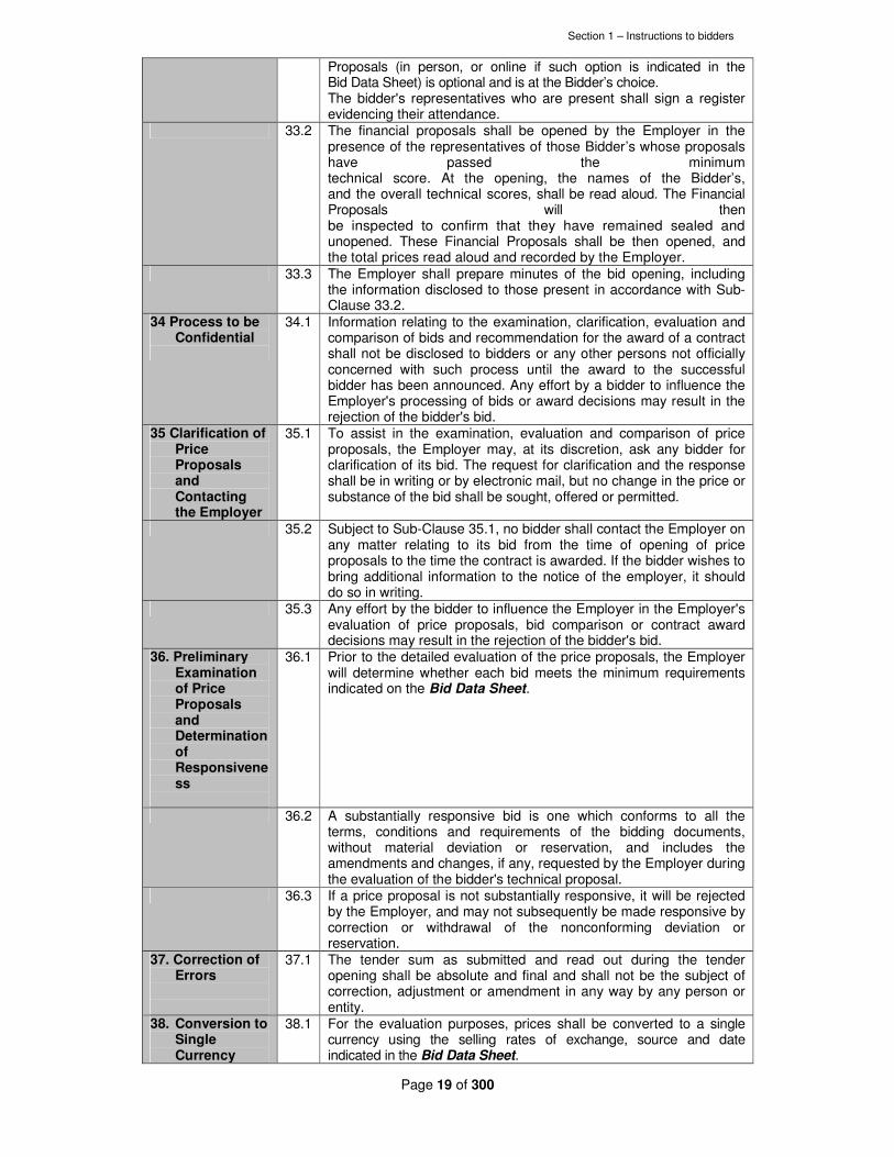
Proposals (in person, or online if such option is indicated in the Bid Data Sheet) is optional and is at the Bidder’s choice. The bidder's representatives who are present shall sign a register evidencing their attendance.
33.2
The financial proposals shall be opened by the Employer in the presence of the representatives of those Bidder’s whose proposals have passed the minimum technical score. At the opening, the names of the Bidder’s, and the overall technical scores, shall be read aloud. The Financial Proposals will then be inspected to confirm that they have remained sealed and unopened. These Financial Proposals shall be then opened, and the total prices read aloud and recorded by the Employer.
33.3
The Employer shall prepare minutes of the bid opening, including the information disclosed to those present in accordance with Sub-Clause 33.2.
34 Process to be Confidential
34.1
Information relating to the examination, clarification, evaluation and comparison of bids and recommendation for the award of a contract shall not be disclosed to bidders or any other persons not officially concerned with such process until the award to the successful bidder has been announced. Any effort by a bidder to influence the Employer's processing of bids or award decisions may result in the rejection of the bidder's bid.
35 Clarification of Price Proposals and Contacting the Employer
35.1
To assist in the examination, evaluation and comparison of price proposals, the Employer may, at its discretion, ask any bidder for clarification of its bid. The request for clarification and the response shall be in writing or by electronic mail, but no change in the price or substance of the bid shall be sought, offered or permitted.
35.2
Subject to Sub-Clause 35.1, no bidder shall contact the Employer on any matter relating to its bid from the time of opening of price proposals to the time the contract is awarded. If the bidder wishes to bring additional information to the notice of the employer, it should do so in writing.
35.3
Any effort by the bidder to influence the Employer in the Employer's evaluation of price proposals, bid comparison or contract award decisions may result in the rejection of the bidder's bid.
36. Preliminary Examination of Price Proposals and Determination of Responsiveness
36.1
Prior to the detailed evaluation of the price proposals, the Employer will determine whether each bid meets the minimum requirements indicated on the Bid Data Sheet.
36.2
A substantially responsive bid is one which conforms to all the terms, conditions and requirements of the bidding documents, without material deviation or reservation, and includes the amendments and changes, if any, requested by the Employer during the evaluation of the bidder's technical proposal.
36.3
If a price proposal is not substantially responsive, it will be rejected by the Employer, and may not subsequently be made responsive by correction or withdrawal of the nonconforming deviation or reservation.
37. Correction of Errors
37.1
The tender sum as submitted and read out during the tender opening shall be absolute and final and shall not be the subject of correction, adjustment or amendment in any way by any person or entity.
38. Conversion to Single Currency
38.1 For the evaluation purposes, prices shall be converted to a single currency using the selling rates of exchange, source and date indicated in the Bid Data Sheet.

Section 1 – Instructions to bidders
Page 20 of 300
39. Evaluation and Comparison of Price Proposals
39.1 The Employer’s evaluation committee shall evaluate and compare only the Price Proposals determined to be substantially responsive in accordance with Clause 36.
40. Margin of Preference
40.1
A margin of preference shall apply as specified in the the Bid Data Sheet.
G. Award of Contract
41. Award 41.1 The Employer will determine the winning bid using any of the
Combined Quality and Cost Evaluation criteria specified in the Bid Data Sheet.
41.2 Each criterion of the Combined Quality and Cost Evaluation criteria to be used to determine the winning bid are as elaborated below:
a) Quality-and Cost-Based Selection(QCBS) In the case of QCBS, the total score is calculated by weighting the technical and financial scores and adding them as per the formula and instructions in the Bid Data Sheet. The Bidder achieving the highest combined technical and financial score will be invited to negotiate the Contract.
b) Fixed-Budget Selection(FBS) In the case of FBS, those Bid prices that exceed the budget indicated in the Bid Data Sheet shall be rejected. The Employer will select the Bidder that submitted the highest-ranked Technical proposal that does not exceed the budget indicated in the Bid document, and invite such Bidder to negotiate the Contract.
c) Least-Cost Selection(LCS) In the case of Least-Cost Selection (LCS), the Employer will select the Bidder with the lowest evaluated Bid price among those Bidders that achieved the minimum technical score, and invite such Bidder to negotiate the Contract.
41.3 Subject to Clause 42, the Employer will award the Contract to the bidder whose bid has been determined to be substantially responsive to the bidding documents and declared the winning bid using one of the criteria in sub-clause 41.2.
42. Employer’s Right to Accept any Bid and to Reject any or all Bids
42.1 Notwithstanding Clause 41, the Employer reserves the right to accept or reject any bid, and to annul the bidding process and reject all bids, at any time prior to award of Contract, without thereby incurring any liability to the affected bidder or bidders.
43. Notification of Award
43.1 The Bidder whose Bid has been accepted will be notified of the award by the Employer prior to expiration of the Bid validity period by e-mail or facsimile confirmed by registered letter. This letter (hereinafter and in the Conditions of Contract called the "Letter of Acceptance") will state the sum that the Employer will pay the Contractor in consideration of the provision and maintenance of the Work(s) as prescribed by the Contract (hereinafter and in the Contract called the “Contract Price”).
43.2 The notification of award will constitute the formation of the Contract, subject to the Bidder furnishing the performance Security in accordance with clause 45 and signing the Contract in accordance with sub-Clause 44.2
43.3 At the same time as the person submitting the successful Bid is notified, the Employer will notify the other bidders that their bids have been unsuccessful.
43.4 If, after notification of award, a Bidder wishes to ascertain the grounds on which its Bid or application for pre-qualification was unsuccessful, it should address its request to the Employer. The Employer shall, within

Section 1 – Instructions to bidders
Page 21 of 300
fourteen days after a request, provide written reasons as to why the bid, proposal or application to be pre-qualified was unsuccessful. However, failure to take this opportunity to clarify the grounds for rejection does not affect the Bidder’s right to seek immediate review by the Public Procurement Administrative Review Board under Clause 2.
44. Signing of Contract Agreement
44.1 Promptly, and in no case later than 14 days, after notification, Employer shall send the successful Bidder the Agreement and Contract Data Sheet all contained in the bidding documents, incorporating all agreements between the parties obtained as a result of Contract negotiation.
44.2 Within the period specified in the notification or Bid Data Sheet but not earlier than fourteen (14) days since notification of award of contract, the successful Bidder shall sign and date the contract and return it to the Employer.
45. Performance Security
45.1 Within thirty (30) days but after 14 days after receipt of the Letter of Acceptance, the successful Bidder shall deliver to the Employer a Performance Security in the amount stipulated in the Bid Data Sheet, denominated in the type and proportions of currencies in the Letter of Acceptance and in accordance with the Conditions of Contract. The Performance Security shall be denominated in the currency of the Bid and shall be in one of the following forms:
(a) Cash;
(b) A Bank Guarantee from a local commercial bank or from an overseas reputable bank or an overseas/ local reputable financial institution. The format of the bank guarantee shall be in accordance with the sample form of performance security included in Section 7; other acceptable formats may be used.
(c) An Insurance Bond from a local reputable insurance firm or an overseas reputable insurance firm;
(d) An irrevocable letter of credit issued by a reputable bank.
45.2 If the Performance Security is provided by the successful Bidder in the
form of a Bank Guarantee or Insurance Bond, it shall be issued either: (a) At the Bidder’s option, by a bank or insurance
firm located in Kenya, or a foreign bank or insurance firm through a correspondent bank or insurance firm located in Kenya;
(b) With the consent of the Employer, directly by a foreign bank acceptable to the Employer.
45.3 Failure of the successful bidder to comply with the requirements of Clauses 44 or 45 shall constitute sufficient grounds for the annulment of the award and forfeiture of the bid security, in which event the Employer may make the award to the next lowest evaluated Bidder or call for new Bids.
46. Advance Payment
46.1 The Employer will provide an advance payment as stipulated in the Conditions of Contract, subject to a maximum amount, or as stated in the Bid Data Sheet. The Advance Payment Security shall be denominated in the currency of the Bid and shall be in one of the following forms:
(a) A Bank Guarantee from a local commercial bank or from an overseas reputable bank or an overseas/ local reputable financial institution. The format of the bank guarantee shall be in accordance with the sample form of Advance Payment security included in Section 7; other acceptable formats may be used.

Section 1 – Instructions to bidders
Page 22 of 300
(b) An Insurance Bond from a local reputable insurance firm or an overseas reputable insurance firm;
(c) An irrevocable letter of credit issued by a reputable bank.
46.2 The Advance Payment shall be accompanied by an Advance Payment
Security.For the purpose of receiving the Advance Payment, the Bidder shall make an estimate of, and include in its Bid, the expenses that will be incurred in order to commence work. These expenses will relate to the purchase of equipment, machinery, materials, and on the engagement of labour during the first month beginning with the date of the Employer’s “Notice to Commence” as specified in the Contract.
H. SOURCING OF FUNDS
47Source of Funds
47.1 The Borrower or Recipient (hereinafter called “Borrower”) indicated in the Bid Data Sheet will be the Government of Kenya Represented by the National Treasury and will jointly with the bidder apply for the funding from the funding agency proposed by the bidder toward the cost of the project named in the Bid Data Sheet. The Borrower intends to apply a portion of the funds to eligible payments under the contract(s) for which this Bidding Document is issued.
47.2 Payments by the proposed Financing Institution (Bank) by the bidder will be made only at the request of the Borrower and upon approval by the Bank in accordance with the terms and conditions of the financing agreement between the Borrower and the Bank (hereinafter called the Loan Agreement), and will be subject in all respects to the terms and conditions of that Loan Agreement. No party other than the Borrower shall derive any rights from the Loan Agreement or have any claim to the funds.
I. BID DATA SHEET(BDS)
BDS Ref. No.
BDS Clause Number
� General
1. 1.1 The Employer is Tanathi Water Services Board a state corporation under
the Ministry of Water and Irrigation. The dam is proposed as a potential
source to supply both Nairobi and Mavoko-kitengela area. The scope of
works involves but not limited to the construction of:
• Ndarugu 1 Dam on Ndarugu River approx. 1Km upstream of the
confluence with Komu River
• Raw Water Pumping Station at Ndarugu 1 Dam Outlet Works
• Raw Water Pumping Main of approximate length of 1Km from
Ndarugu 1 Dam to a Proposed Water Treatment Site
• Water Treatment works, capacity 173,000m3/d
• Treated Water Pumping Station at the proposed Water treatment
site, capacity 173,000m3/d
• Treated Water Pumping Main of approximate length of 30Km from
the pumping station to Utawala Tank, capacity 173,000m3/d

Section 1 – Instructions to bidders
Page 23 of 300
• Treated water pumping main of approximate length of 13km from
utawala tank to ring road tank, capacity 35,000m3/d
• Treated water pumping main of approximate length of 6km from
utawala tank to Embakasi tank, capacity 38,000m3/d
• Treated water pumping main of approximate length of 14km from
utawala tank to Syokimau tank, capacity 50,000m3/d
• Treated water pumping main of approximate length of 40Km from Utawala Tank to Koma Tank, capacity 25,000m3/d
• Utawala, Embakasi, Syokimau, Mavoko, & Koma Tanks
• Distribution mains from Syokimau reservoir to syokimau/mlolongo,
Athi River and Kitengela areas.
• Distribution Mains from Koma Reservoir to Nguluni, Tala and Kangundo town.
2. 1.2 The successful bidder will be expected to complete the Works in Three (3) yrs from the date of handing over site.
3. 2.3 The address for submitting appeals to Administrative Review Board : The Secretary, Public Procurement Administrative Review Board, The Public Procurement Oversight Authority, 10th Floor ,National Bank House, P.O. Box 58583-00200, NAIROBI, Kenya. Tel: +254 (0) 20 3244000 Email: [email protected] Website: www.ppoa.go.ke
4. 9.4 A site visit will take place at: VENUE: Mavoko Water and Sewerage Company DATE: 9
th November, 2017
TIME: 09.00Hrs
5. 9.5 Non-attendance during the site visit WILL NOT lead to disqualification.
6. � Bidding Documents
7. 11.1 Address for clarification of Bid Document is: The Chief Executive Officer, Tanathi Water Services Board K.I.D.P. Building, Kalawa Road P.O. Box Private Bag Kitui Tel: 0712 351 104 Email: [email protected] / [email protected]
Period to Respond to request for clarification by the Employer is 7 days Prior to deadline for submission of Bids.

Section 1 – Instructions to bidders
Page 24 of 300
� Preparation of Bids 8. 13.1 The Bid as well as all correspondence and documents relating to the bid
exchanged by the Bidder and the Employer, shall be written in ENGLISH.
9. 17.1 The unit rates and prices shall be quoted in KENYA SHILLING.
10. 17.2 The authority for establishing the rates of exchange shall be CENTRAL
BANK OF KENYA
11. 18.1 The Bid validity period shall be 180 days.
12. 19.1 The amount of Bid Security shall be at least 1% of the contract price
13. 19.2 The bid security shall remain valid for 180 days after the Bid submission deadline, and beyond any period of extension subsequently requested under Sub-Clause 18.2.
14. 20.1 Alternative proposals will not be considered.
15. 20.2 Alternative completion time will not be allowed.
16. 21.1 A pre-bid meeting will take place at:
VENUE: Mavoko Water and Sewerage Company DATE: 9
th November, 2017
TIME: 09.00Hrs
17. 21.3 The bidder is requested to submit any questions in writing or by fax, to reach the Employer not later than 7 days prior to the meeting.
18. 21.4 Minutes of the pre-bid meeting, including the text of the questions raised, without identifying the source, and the responses given, together with any response prepared after the meeting, will be transmitted within 7 days to all Bidders.
19. 21.5 Nonattendance at the pre-bid meeting WILL NOT be a cause for disqualification of a bidder.
20. 22.1 The number of copies to be completed and returned with the Tender is 3 (THREE)
� Submission of Bids
21. 23.1
The bidder shall seal the original copy of the technical proposal, the original copy of the price proposal and each copy of the technical proposal and each copy of the price proposal in separate envelopes clearly marking each one as: “ORIGINAL TECHNICAL PROPOSAL”, ÖRIGINAL PRICE PROPOSAL”, “and COPY NO. 1 – TECHNICAL PROPOSAL”, “COPY NO 1- PRICE PROPOSAL” etc. as appropriate.
22. 23.2 The Bidder shall seal the original bids and each copy of the bids in an inner and an outer envelope, duly marking the envelopes as “ORIGINAL” and “COPY”.
23. 23.3 The inner and outer envelopes shall be addressed to: The Chief Executive Officer, Tanathi Water Services Board K.I.D.P. Building, Kalawa Road
Section 1 – Instructions to bidders
Page 25 of 300
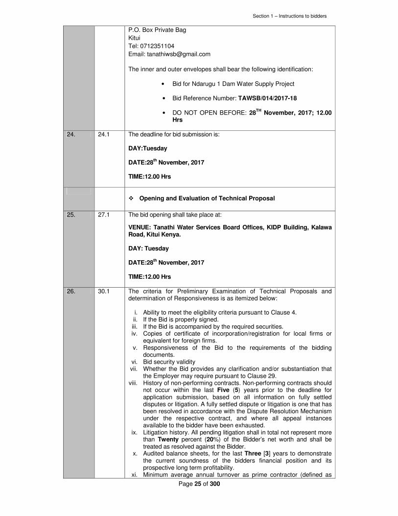
P.O. Box Private Bag Kitui Tel: 0712351104 Email: [email protected] The inner and outer envelopes shall bear the following identification:
• Bid for Ndarugu 1 Dam Water Supply Project
• Bid Reference Number: TAWSB/014/2017-18
• DO NOT OPEN BEFORE: 28TH
November, 2017; 12.00 Hrs
24. 24.1 The deadline for bid submission is: DAY:Tuesday DATE:28
th November, 2017
TIME:12.00 Hrs
� Opening and Evaluation of Technical Proposal
25. 27.1
The bid opening shall take place at:
VENUE: Tanathi Water Services Board Offices, KIDP Building, Kalawa Road, Kitui Kenya. DAY: Tuesday DATE:28
th November, 2017
TIME:12.00 Hrs
26. 30.1
The criteria for Preliminary Examination of Technical Proposals and determination of Responsiveness is as itemized below:
i. Ability to meet the eligibility criteria pursuant to Clause 4. ii. If the Bid is properly signed. iii. If the Bid is accompanied by the required securities. iv. Copies of certificate of incorporation/registration for local firms or
equivalent for foreign firms. v. Responsiveness of the Bid to the requirements of the bidding
documents. vi. Bid security validity vii. Whether the Bid provides any clarification and/or substantiation that
the Employer may require pursuant to Clause 29. viii. History of non-performing contracts. Non-performing contracts should
not occur within the last Five (5) years prior to the deadline for application submission, based on all information on fully settled disputes or litigation. A fully settled dispute or litigation is one that has been resolved in accordance with the Dispute Resolution Mechanism under the respective contract, and where all appeal instances available to the bidder have been exhausted.
ix. Litigation history. All pending litigation shall in total not represent more than Twenty percent (20%) of the Bidder’s net worth and shall be treated as resolved against the Bidder.
x. Audited balance sheets, for the last Three [3] years to demonstrate the current soundness of the bidders financial position and its prospective long term profitability.
xi. Minimum average annual turnover as prime contractor (defined as

Section 1 – Instructions to bidders
Page 26 of 300
billing for works in progress and completed) over the last Five (5) years of 10 Billion Kenya Shillings.
xii. The Bidder must demonstrate access to, or availability of, financial resources such as liquid assets, unencumbered real assets, lines of credit, and other financial means, other than any contractual advance payments to meet:
a) A construction cash-flow requirement of One Billion (1,000,000,000) Kenya Shillings
b) The overall cash flow requirements for this contract and its current commitments.
xii. General experience under contracts in the role of contractor, subcontractor, or management contractor for at least the last Five [5] years prior to the applications submission deadline.
xiii. Specific Experience: a) Successful experience as a contractor, management
contractor, or subcontractor, in the execution of at least One (1) project of a nature and complexity comparable to the proposed contract within the last Ten (10) years, with a value of at least Eighteen Billion (18 Billion) Kenya Shilling. The similarity shall be based on the complexity, methods/technology or other characteristics as described in Section IV, Employer’s Requirements.
b) For the above or other contracts executed during the period stipulated in xiii (a) above, this experience should include minimum key production rates of:
� Laying of water pipes 800mm dimeter at a rate of 2850m per month
� Earthworks at a rate of 130,000 cubic meters per month
� Concrete works at a rate 3000 cubic meters per month.
xiv. Necessary equipment for construction of dam, water treatment plant, transmission pipeline, storage tanks shall be required. The Applicant should own, or have proved access (through hire, lease, purchase agreement, availability of manufacturing equipment, or other means) to at least the following key items of equipment in full working order, and must demonstrate that, based on known commitments, they will be available for use in the proposed contract. The Applicant shall own at least 50% of the heavy construction equipment considered necessary for the successful execution of works. He shall provide for each of these equipment a copy of the registration document and / or copy of the purchase invoice mentioning supplier’s name and address, date of purchasing. The Applicant may also list alternative equipment that it would propose for the contract, together with an explanation of the proposal. Equipment type and characteristics
Minimum number required
Excavators 4 Lorries (7 ton) 2
Tippers (15 ton) 14 Dumpers 4
Tractors 2
Concrete Mixers including batch weighing
6
batching plant >40m3/h 1 crushing/screening plant 1
concrete pump > 20m3/h, 1 Concrete Vibrators 35mmØ 4
Cranes (5 ton) 2 Compressors (5,000 l/min) 2

Section 1 – Instructions to bidders
Page 27 of 300
Generator (15kVA) 2
Generator (150kVA) 1
Total Station 2 Trailers (10 ton) 1
Bar Bending Machine 2 Dewatering pumps 4
Drilling equipment, 1
diaphragm wall equipment 1
vibratory roller > 20t 1 mobile crane 1
xv. Environnemental and Social Clause
The Applicant shall undertake to respect national and international norms on the protection of the environment and labour laws applicable in Kenya where the Project is being implemented, including the ILO fundamental agreements and international agreements on environment in order to promote sustainable development that respect environment and social norms. In the case where the norms are not observed, the Employer will take all appropriate measures; to implement an approach of controlling the environmental and social risks in particular applying mitigation measures in the conditions agreed; to require the Contractor to apply these mitigation measures and that they ensure that these measures are respected by their sub-contractors and in case of any breach, to take all appropriate measures. The Applicant shall provide the Employer with a summarized social and environmental notice describing succinctly:
- The company’s commitment to comply with the social and environmental clauses stipulated above and to have them complied by his sub-contractors
- The outline of the company’s internal social policy - The outline of the company’s hygiene and security
policy - The outline of the company’s internal environmental
policy, mentioning possible classifications used by the Applicant and how this policy joins the company’s quality policy
- The Applicant’s understanding of social and environmental stakes of the project
Bid(s) NOT satisfying the above criteria shall be declared NON RESPONSIVE and rejected by the Employer.
27. 30.2
A substantially responsive bid is one which conforms to all the terms, conditions and requirements of the bidding documents, without material deviation or reservation. A material deviation or reservation is one:
i. which affects in any substantial way the scope, quality or performance of the Works;
ii. which is inconsistent with the bidding documents and limits in any substantial way, the Employer’s rights or the bidder's obligations under the Contract; or
iii. whose rectification would affect unfairly the competitive position of other bidders presenting substantially responsive bids.
28. 30.3
If a bid is not substantially responsive, it will be rejected by the Employer, and may not subsequently be made responsive by correction or withdrawal of the nonconforming deviation or reservation.
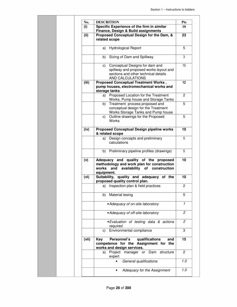
29. 31.1 The Criteria, sub-criteria, and point system for the Evaluation and Comparison of Technical Proposals is as itemized below:
Section 1 – Instructions to bidders
Page 28 of 300
No. DESCRITION Pts
(i) Specific Experience of the firm in similar Finance, Design & Build assignments
10
(ii) Proposed Conceptual Design for the Dam, & related scope
23
a) Hydrological Report 5
b) Sizing of Dam and Spillway
3
c) Conceptual Designs for dam and spillway and proposed works layout and sections and other technical details AND CALCULATIONS
15
(iii) Proposed Conceptual Treatment Works , pump houses, electromechanical works and storage tanks
12
a) Proposed Location for the Treatment Works, Pump house and Storage Tanks
2
b) Treatment process proposed and conceptual design for the Treatment Works Storage Tanks and Pump house
5
c) Outline drawings for the Proposed Works
5
(iv) Proposed Conceptual Design pipeline works & related scope
10
a) Design concepts and preliminary calculations
5
b) Preliminary pipeline profiles (drawings) 5
(v) Adequacy and quality of the proposed methodology and work plan for construction works and availability of construction equipment.
10
(vi) Suitability, quality and adequacy of the proposed quality control plan.
10
a) Inspection plan & field practices 2
b) Material tesing 5
• Adequacy of on-site laboratory 1
• Adequacy of off-site laboratory 2
• Evaluation of testing data & actions required
2
c) Environmental compliance 3
(vii) Key Personnel’s qualifications and competence for the Assignment for the works and design services.
15
a) Project manager or Dam structure expert
2
• General qualifications 1.0
• Adequacy for the Assignment 1.0

Section 1 – Instructions to bidders
Page 29 of 300
b) Geologist 1
• General qualifications 0.5
• Adequacy for the Assignment 0.5
c) Dam Safety/ Instrumentation expert 1
• General qualifications 0.5
• Adequacy for the Assignment 0.5
d) Site Agent 1
• General qualifications 0.5
• Adequacy for the Assignment 0.5
e) Materials Engineer 1
• General qualifications 0.5
• Adequacy for the Assignment 0.5
f) Site Measurements Engineer/ Quantity Surveyor
1
• General qualifications 0.5
• Adequacy for the Assignment 0.5
g) Site Engineering Surveyor 1
• General qualifications 0.5
• Adequacy for the Assignment 0.5
h) Environmental specialist 1
• General qualifications 0.5
• Adequacy for the Assignment 0.5
i) Hydraulic Engineer 1
• General qualifications 0.5
• Adequacy for the Assignment 0.5
j) Social Economist 1
• General qualifications 0.5
• Adequacy for the Assignment 0.5
k) Hydrologist 1
• General qualifications 0.5
• Adequacy for the Assignment 0.5
Section 1 – Instructions to bidders
Page 30 of 300
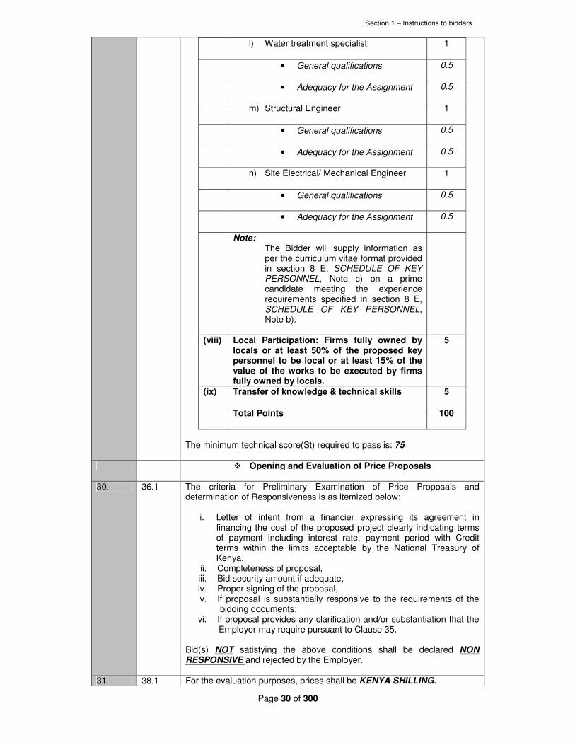
l) Water treatment specialist 1
• General qualifications 0.5
• Adequacy for the Assignment 0.5
m) Structural Engineer 1
• General qualifications 0.5
• Adequacy for the Assignment 0.5
n) Site Electrical/ Mechanical Engineer 1
• General qualifications 0.5
• Adequacy for the Assignment 0.5
Note: The Bidder will supply information as per the curriculum vitae format provided in section 8 E, SCHEDULE OF KEY PERSONNEL, Note c) on a prime candidate meeting the experience requirements specified in section 8 E, SCHEDULE OF KEY PERSONNEL, Note b).
(viii) Local Participation: Firms fully owned by locals or at least 50% of the proposed key personnel to be local or at least 15% of the value of the works to be executed by firms fully owned by locals.
5
(ix) Transfer of knowledge & technical skills 5
Total Points 100
The minimum technical score(St) required to pass is: 75
� Opening and Evaluation of Price Proposals
30. 36.1
The criteria for Preliminary Examination of Price Proposals and determination of Responsiveness is as itemized below:
i. Letter of intent from a financier expressing its agreement in financing the cost of the proposed project clearly indicating terms of payment including interest rate, payment period with Credit terms within the limits acceptable by the National Treasury of Kenya.
ii. Completeness of proposal, iii. Bid security amount if adequate, iv. Proper signing of the proposal, v. If proposal is substantially responsive to the requirements of the
bidding documents; vi. If proposal provides any clarification and/or substantiation that the
Employer may require pursuant to Clause 35. Bid(s) NOT satisfying the above conditions shall be declared NON RESPONSIVE and rejected by the Employer.
31. 38.1 For the evaluation purposes, prices shall be KENYA SHILLING.
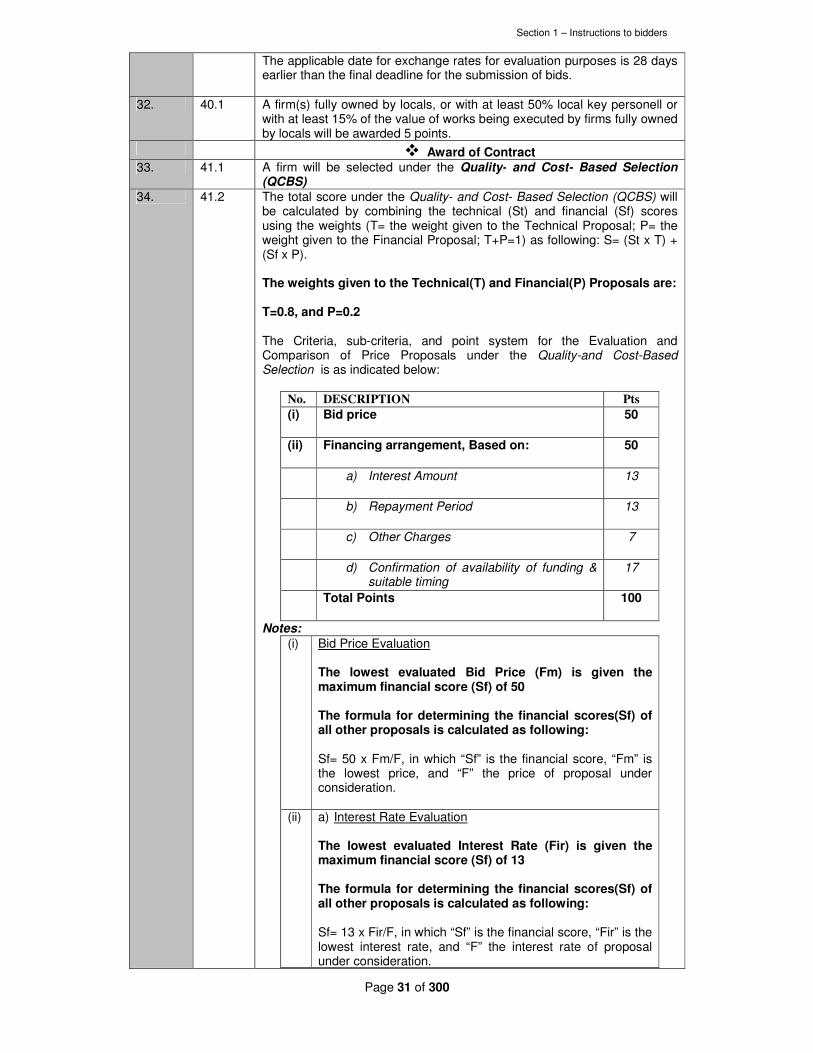
Section 1 – Instructions to bidders
Page 31 of 300
The applicable date for exchange rates for evaluation purposes is 28 days earlier than the final deadline for the submission of bids.
32. 40.1 A firm(s) fully owned by locals, or with at least 50% local key personell or with at least 15% of the value of works being executed by firms fully owned by locals will be awarded 5 points.
� Award of Contract 33. 41.1 A firm will be selected under the Quality- and Cost- Based Selection
(QCBS) 34. 41.2 The total score under the Quality- and Cost- Based Selection (QCBS) will
be calculated by combining the technical (St) and financial (Sf) scores using the weights (T= the weight given to the Technical Proposal; P= the weight given to the Financial Proposal; T+P=1) as following: S= (St x T) + (Sf x P). The weights given to the Technical(T) and Financial(P) Proposals are: T=0.8, and P=0.2 The Criteria, sub-criteria, and point system for the Evaluation and Comparison of Price Proposals under the Quality-and Cost-Based Selection is as indicated below:
No. DESCRIPTION Pts
(i) Bid price
50
(ii) Financing arrangement, Based on: 50
a) Interest Amount 13
b) Repayment Period 13
c) Other Charges 7
d) Confirmation of availability of funding & suitable timing
17
Total Points 100
Notes:
(i) Bid Price Evaluation The lowest evaluated Bid Price (Fm) is given the maximum financial score (Sf) of 50 The formula for determining the financial scores(Sf) of all other proposals is calculated as following: Sf= 50 x Fm/F, in which “Sf” is the financial score, “Fm” is the lowest price, and “F” the price of proposal under consideration.
(ii) a) Interest Rate Evaluation The lowest evaluated Interest Rate (Fir) is given the maximum financial score (Sf) of 13 The formula for determining the financial scores(Sf) of all other proposals is calculated as following: Sf= 13 x Fir/F, in which “Sf” is the financial score, “Fir” is the lowest interest rate, and “F” the interest rate of proposal under consideration.

Section 1 – Instructions to bidders
Page 32 of 300
b) Repayment Period Evaluation The longest evaluated repayment period (Frp) is given the maximum financial score (Sf) of 13 The formula for determining the financial scores(Sf) of all other proposals is calculated as following: Sf= 13 x F/Frp, in which “Sf” is the financial score, “Frp” is the longest repayment period, and “F” the repayment period of proposal under consideration.
c) Other Charges Evaluation
The lowest evaluated other charges (Foc) is given the maximum financial score (Sf) of 7 The formula for determining the financial scores(Sf) of all other proposals is calculated as following: Sf= 7 x Foc/F, in which “Sf” is the financial score, “Foc” is the lowest other charges, and “F” the other charges of proposal under consideration.
d) Confirmation of availability of funding & suitable timing
The Shortest evaluated time taken to mobilize the financing (Fmf) is given the maximum financial score (Sf) of 17 The formula for determining the financial scores(Sf) of all other proposals is calculated as following: Sf= 17 x Fmf/F, in which “Sf” is the financial score, “Fmf” is the shortest time taken to mobilize financing, and “F” the time taken to mobilize financing of proposal under consideration.
35. 41.3 Subject to Clause 42, the Employer will award the Contract to the bidder whose bid has been determined to be substantially responsive to the bidding documents and who has achieved the highest combined technical and financial score as per the Quality- and Cost- Based Selection (QCBS)
36. 44.2 Within 7days but not earlier than fourteen (14) days since notification of award of contract, the successful Bidder shall sign and date the contract and return it to the Employer.
37. 45.1 The amount of performance security shall be Ten (10) Percent of the Contract Price.
38. 46.1 The amount of advance payment shall be Twenty (20) Percent of the Contract Price.
39. 47.1 The Borrower is the Government of the Republic of Kenya

Section 2 – General Conditions of Contract _____________________________________________________________________________________________
____
Page 33 of 300
Section 2. Part I – General Conditions of Contract

Section 2 – General Conditions of Contract _____________________________________________________________________________________________
____
Page 34 of 300
Section 2. Part I – General Conditions
The Conditions of Contract comprise two parts: Part I – General Conditions (Section 2
of this document), and Part II – Conditions of Particular Application (Section 3 of this
document) as per FIDIC Plant and Design Build First Edition 1999.
Copies of the FIDIC Conditions of Contract for Plant and Design-Build First Edition
1999 can be obtained from:
FIDIC Secretariat
P.O. Box 86
1000 Lausanne 12
Switzerland
Facsimile: 41 21 653 5432
Telephone: 41 21 653 5003

Section 3 – Conditions of Particular Applications _____________________________________________________________________________________________
____
Page 35 of 300
Section 3. Part II –Conditions of Particular Application
1. General Provisions
Sub-Clause 1.1.1 The Contract
Amend Subpara. 1.1.1.1 (“Contract”) by adding the following at the end: “The words ‘Agreement’ and ‘Contract’ are used interchangeably.”
Amend Subpara. 1.1.1.8 (“Tender”) by adding the following at the end: “The word ‘tender’ is synonymous with ‘Bid,’ and the words ‘Letter of Tender’ with ‘Letter of Bid’, and the words ‘Appendix to Tender’ with ‘Appendix to Bid,’ and the words ‘tender documents’ with ‘Bidding Documents.’”
Sub-Clause 1.1.3 Dates, Tests, Periods and
Completion
Amend Sub-Para. 1.1.3.7 by inserting the following after the reference to Sub-Clause 11.1: “which extends over twelve months except if otherwise stated in the Appendix to Bid”.
Sub-Clause 1.4 Replace the text of Sub-Clause 1.4 and add the following: "The law of the Contract is the law of Kenya. “The language is the English language"
Sub-Clause 1.5 Priority of Documents
Delete the list of documents listed under (a) to (h) and add the following:
"(a) the Contract Agreement;
(b) the Letter of Acceptance; (c) the Employer’s Requirements; (d) the Bid; (e) the Conditions of Contract, Part II; (f) the Conditions of Contract, Part I; (g) the Schedules; (h) the Drawings; and (i) the Contractor’s Proposal."
Sub-Clause 1.12 Confidential Details
Replace the text of Sub-Clause 1.12 with the following: “The Contractor’s and the Employer’s Personnel shall disclose all such confidential and other information as may be reasonably required in order to verify the Contractor’s compliance with the Contract and allow its proper implementation; provided that the requirements of this Sub-Clause 1.12 shall not apply to authorized Representatives of the Employer and the Employer’s Audit. “Each of the Parties shall treat the details of the Contract as private and confidential, except to the extent necessary to carry out their respective obligations under the Contract or to comply with applicable Laws. Each of them shall not publish or disclose any particulars of the design and of the Works prepared by the other Party without the previous agreement of the other Party. However, the Contractor shall be permitted to disclose any publicly available information, or, with the prior consent of the

Section 3 – Conditions of Particular Applications _____________________________________________________________________________________________
____
Page 36 of 300
Employer, information otherwise reasonably required to establish its qualifications to compete for other projects. If any dispute arises as to the necessity of any publication or disclosure of the details of the Contract, the same shall be referred to the Employer whose determination shall be final. The Contractor shall ensure that the requirements imposed on the Contractor by this Sub-Clause apply equally to each Subcontractor.”
Sub-Clause 1.13 Compliance with Laws
Amend Sub-Clause 1.13(b) by adding the following at the end: “unless the Contractor is impeded to accomplish these actions and shows evidence of its diligence.”
Sub-Clause 1.14 Joint and Several Liability
Amend Sub-Clause 1.14(a) by adding the following at the end: “or these persons shall be jointly and severally liable to the Employer for the performance of the Contract as defined in their Agreement.”
Replace Sub-Clause 1.14(b) with “ these persons shall be bound to the Employer as defined in their Agreement”
3. The Engineer
Sub-Clause 3.1 Engineer’s Duties and Authority
Amend Sub-Clause 3.1 by replacing the word “may” in the first sentence of the third paragraph with the word “shall”. Amend Subpara. (b) of Sub-Clause 3.1 by deleting the word “and” at the end. Amend Subpara. (c) of Sub-Clause 3.1 by replacing the period at the end with “; and”.
Amend Sub-Clause 3.1 by adding the following at the end: “(d) any act by the Engineer in response to a Contractor’s request
except otherwise expressly specified shall be notified in writing to the Contractor within 28 days of receipt.
“The following provisions also shall apply: “The Engineer shall obtain the specific approval of the Employer before taking action under the-following Sub-Clauses of these Conditions:
(i) Sub-Clause 4.12 [Unforeseeable Physical Conditions]: Agreeing to or determining an extension of time and/or additional cost.
(ii) Sub-Clause 10.1 [Taking-over of the Works and Sections]: Prior to issuing Taking-Over Certificate.
(iii) Sub-Clause 11.9 [Performance Certificate]: Prior to issuing Performance Certificate.
(iv) Sub-Clause 13.1 [Right to Vary]: Instructing a Variation, except if such a Variation would increase the Accepted Contract Amount by less than the percentage specified in the Appendix to Bid.
(v) Sub-Clause 13.3 [Variation Procedure]: Approving a proposal for Variation submitted by the Contractor in accordance with Sub-Clause 13.1 [Right to Vary] or 13.2 [Value Engineering], except if such a Variation would increase the Accepted Contract Amount by

Section 3 – Conditions of Particular Applications _____________________________________________________________________________________________
____
Page 37 of 300
less than the percentage specified in the Appendix to Bid.
(vi) Sub-Clause 13.4 [Payment in Applicable Currencies]: Specifying the amount payable in each of the applicable currencies.
“Notwithstanding the obligation, as set out above, to obtain approval, if, in the opinion of the Engineer, an emergency occurs affecting the safety of life or of the Works or of adjoining property, he may, without relieving the Contractor of any of his duties and responsibility under the Contract, instruct the Contractor to execute all such work or to do all such things as may, in the opinion of the Engineer, be necessary to abate or reduce the risk. The Contractor shall forthwith comply, despite the absence of approval of the Employer, with any such instruction of the Engineer. Within 7 days of having issued such emergency instructions, the Engineer shall submit written documentation of such instructions to the Employer. The Engineer shall determine an addition to the Contract Price, in respect of such instruction, in accordance with Clause 13 [Variations and Adjustments] and shall notify the Contractor accordingly, with a copy to the Employer.”
4. The Contractor
Sub-Clause 4.1 Contractor’s General Obligations
(a) Add the following sentence to precede the existing text under Sub-Clause 4.1: "The Contractor is required to check the design criteria and calculations (if any) included in the Employer’s Requirements, to confirm their correctness, in its bid and to assume full responsibility for them."
‘Amend sub-clause 4.1 by adding the following at the end’.
“The Contractor and its Subcontractors, including their respective personnel and affiliates, shall at all times during the term of this Contract have the nationality of a country or territory eligible, in accordance with the contract., The Contractor or a Subcontractor and their respective personnel and affiliates shall be deemed to have the nationality of a country if it is a citizen or constituted, incorporated, or registered, and operates in conformity with the provisions of the laws of that country.
“All Equipment, Materials, Plant and any services to be incorporate in or required for the Works shall have their origin in Eligible Countries.
“For the purpose of this Sub-Clause 4.1, “origin” means the place where the Equipment, Materials or Plant have been mined, grown, cultivated, produced, manufactured, or processed; or through manufacture, processing, or assembly, another commercially recognized article results that differs substantially in its basic characteristics, purposes or utility from its underlying components. With respect to any services, the term “origin” means the place from which the services are supplied.”
Sub-Clause 4.2 Performance Security
Amend Sub-Clause 4.2 by adding the following at the end: “Without limitation to the other provisions of this Sub-Clause 4.2, whenever the Engineer determines an addition to the Contract Price as a result of a change in cost and/or legislation or as a result of a Variation amounting to more than 10 percent of the portion of the Contract Price payable in a specific currency, the Contractor, at the Engineer’s written request, shall promptly increase the value of the Performance Security in the applicable currency by an equal percentage.
Section 3 – Conditions of Particular Applications _____________________________________________________________________________________________
____
Page 38 of 300
The Performance Security shall be in the form of a Bank Guarantee or Insurance Bond, it shall be issued either at the Bidder’s option, by a bank or insurance firm located in Kenya, or a foreign bank or insurance firm through a correspondent bank or insurance firm located in Kenya The performance security shall be denominated in the types and proportions of currencies in which the Contract Price is payable. The cost of complying with the requirements of this clause shall be borne by the contractor.
Sub-Clause 4.3 Contractor’s Representative
Amend Sub-Clause 4.3 by adding the following at the end: “If the Engineer determines that the Contractor’s Representative or any of these persons are not fluent in the said language, the Contractor shall make competent interpreters available during all working hours in a number deemed sufficient by the Engineer.”
Sub-Clause 4.8 Safety Procedures
Amend Sub-Clause 4.8 by adding the following at the end: “The Contractor shall notify the Engineer and Employer within 48 hours or as soon as reasonably possible after the occurrence of any accident which has resulted in damage or loss of property, disability or loss of human life, or which has or which could reasonably be foreseen to have a material impact on the environment and shall submit to the Engineer and Employer no later than 28 days after the occurrence of such an event, a summary report thereof.”
Sub-Clause 4.18 Protection of the Environment
Amend Sub-Clause 4.18 by adding the following at the end: “The Contractor shall be responsible for ensuring that all Subcontractor’s and Contractor’s Personnel understand and operate in accordance with the principles and requirements of the environmental and social impacts provisions of this Sub-Clause. “The Contractor’s program shall demonstrate clearly the procedures and methods of working that the Contractor and its Subcontractors will adopt to comply with the environmental and social impacts requirements of this Sub-Clause. “The Contractor shall ensure the adequate disposal of construction and excavation wastes. “The Contractor shall restore the Site to original conditions or to a state as set out in the Employer’s Requirements after the completion of the Works.”
Sub-Clause 4.21 Progress Reports
Amend Sub-Clause 4.21 by adding the following at the end: “Within 7 days of the submission by the Contractor of each monthly progress report, the Engineer and the Employer shall meet with the Contractor to discuss the progress of the Works.”
5. Design
Sub-Clause 5.4 Technical Standards and Regulations
Add the following sentence to the end of the Sub-Clause 5.4: "In respect of technical specifications and standards, any national or international standards which promise to confer equal or better quality than the standards specified will also be acceptable."

Section 3 – Conditions of Particular Applications _____________________________________________________________________________________________
____
Page 39 of 300
6. Staff and Labor
Sub-Clause 6.4 [Labour Laws]
To add at the end of this sub-clause: Notwithstanding the above provisions and any other provisions under Part I, the employer and the contractor shall comply with the following: 1.1 (a) The rates of remuneration and other conditions of work of the
employees of the Contractor shall not be less favourable than those established for work of the same character in the trade concerned-
(i) by collective agreement applying to a substantial proportion of the workers and employers in the trade concerned;
(ii) by arbitration awards
(b) Where remuneration and conditions of work are not regulated in a manner referred to at (a) above, the rates of the remuneration and other conditions of work which are not less favourable than the general level observed in the trade in which the contractor is engaged by employers whose general circumstances are similar.
1.2 No contractor shall be entitled to any payment in respect of work performed in the execution of the contract unless he has, together with his claim for payment, filed a certificate:
(a) stating the rates of remuneration and hours of work of the various categories of employees employed in the execution of the contracts;
(b) stating whether any remuneration payable in respect of work done is due;
(c) containing such other information as the authorized officer administering the contract may require to satisfy himself that the provisions under this clause have been complied with.
1.3 Where the authorized officer is satisfied that remuneration is still due to an employee employed under this contract at the time the claim for payment is filed, he may, unless the remuneration is sooner paid by the Contractor, arrange for the payment of the remuneration out of the money payable under this contract.
Sub-Clause 6.8 Contractor’s Superintendence
Amend Sub-Clause 6.8 by adding the following at the end: “If the Engineer determines that the Contractor’s Personnel providing superintendence have inadequate knowledge of such language, the Contractor shall make competent interpreters available during all working hours in a number deemed sufficient by the Engineer.”
Sub-Clause 6.12 Foreign Personnel
Add the following Sub-Clause 6.12: “The Contractor may bring in to the Country any foreign personnel who are necessary for the execution of the Works to the extent allowed by the applicable Laws. The Contractor shall ensure that these personnel are provided with the required residence visas and work permits. The Employer will, if requested by the Contractor, use his best endeavors in a timely and expeditious manner to assist the Contractor in obtaining any local, state, national, or government permission required for bringing in the Contractor’s personnel.

Section 3 – Conditions of Particular Applications _____________________________________________________________________________________________
____
Page 40 of 300
“The Contractor shall be responsible for the return of these personnel to the place where they were recruited or to their domicile. In the event of the death in the Country of any of these personnel or members of their families, the Contractor shall similarly be responsible for making the appropriate arrangements for their return or burial.”
Sub-Clause 6.13 Prohibition of Harmful Child Labor
Add the following Sub-Clause 6.13: “The Contractor shall not employ any child to perform any work that is economically exploitative, or is likely to be hazardous to, or to interfere with, the child's education, or to be harmful to the child's health or physical, mental, spiritual, moral, or social development.”
Sub-Clause 6.14 Employment Records of Workers
Add the following Sub-Clause 6.14: “The Contractor shall keep complete and accurate records of the employment of labor at the Site. The records shall include the names, ages, genders, hours worked and wages paid to all workers. These records shall be summarized on a monthly basis and submitted to the Engineer, and these records shall be available for inspection by auditors during normal working hours. These records shall be included in the details to be submitted by the Contractor under Sub-Clause 6.10 [Records of Contractor’s Personnel and Equipment].”
Sub-Clause 6.15 Measures against Insect & Pest Nuisance
The Contractor shall at all times take the necessary precautions to protect all staff and labour employed on the Site from insect and pest nuisance, and to reduce the dangers to health and the general nuisance occasioned by the same. The Contractor shall provide its staff and labour with suitable prophylactics for the prevention of malaria and take steps to prevent the formation of stagnant pools of water. The Contractor shall comply with all the regulations of the local health authorities and shall arrange to spray thoroughly with approved insecticide all buildings erected on the Site. Such treatment shall be carried out at least once a year or as instructed by such authorities."
Sub-Clause 6.16 Epidemics
In the event of any outbreak of illness of an epidemic nature, the Contractor shall comply with and carry out such regulations, orders and requirements as may be made by the Government or the local medical or sanitary authorities, for the purpose of dealing and overcoming the same."
Sub-Clause 6.17 Alcoholic Liquors or Drug
"The Contractor shall not, otherwise than in accordance with the statutes, ordinances and government regulations or orders for the time being in force, import, sell, give, barter or otherwise dispose of any alcoholic liquor or drugs, or permit or suffer any such importation, sale, gift, barter or disposal by his Subcontractors, agents staff or labour."
Sub-Clause 6.18 Arms and Ammunition
“The contractor shall not give, barter or otherwise dispose of to any person or persons, any arms or ammunition of any kind or permit or suffer to the same as aforesaid.”
Sub-Clause 6.19 Festivals and Religious Customs
The Contractor shall in all dealings with his staff and labour have due regard to all recognized festivals, days of rest and religious or other customs.”
7. Plant, Materials and Workmanship
Sub-Clause 7.7 Add the following sub-clause after sub-clause 7.8

Section 3 – Conditions of Particular Applications _____________________________________________________________________________________________
____
Page 41 of 300
Ownership of Plant and Materials
(a) Any materials, equipment, services or design services which will be incorporated in or required for the Contract, as well as the Contractor’s Equipment and other supplies, shall have their origin in eligible source countries.
(b) For the purpose of this clause, "services" means the works and
all project-related services including design services. (c) For the purposes of this clause, "origin" means the place where
the materials and equipment were mined, grown, produced, or manufactured, or from which the services are provided.
(d) The origin of Goods and Services is distinct from the nationality
of the Supplier."
8. Commencement, Delays and Suspension
Sub-Clause 8.6 Rate of Progress
Amend Sub-Clause 8.6 by inserting the following at the end: “Additional costs of revised methods, including acceleration measures, instructed by the Engineer to reduce delays resulting from causes listed under Sub-Clause 8.4 [Extension of Time for Completion] shall be paid by the Employer, without generating, however, any other additional payment benefit to the Contractor.”
Sub-Clause 8.12 Resumption of Work
Amend Sub-Clause 8.12 by inserting the following at the end: “after receiving from the Engineer an instruction to this effect under Clause 13 [Variations and Adjustments].”
11. Defects Liability
Sub-Clause 11.3 Extension of Defects Notification Period
Amend Sub-Clause 11.3 by inserting the following at the end of the first sentence of the first paragraph: “attributable to the Contractor.”
13. Variations and Adjustments
Sub-Clause 13.1 Right to Vary
Amend Sub-Clause 13.1 by deleting the word “or” at the end of clause (ii) in the second paragraph and by inserting the following at the end of the first sentence of the second paragraph: “or (iv) such Variation triggers a substantial change in the sequence or progress of the Works.”
Sub-Clause 13.7 Adjustments for Changes in Legislation
Amend Sub-Clause 13.7 by adding the following at the end: “Notwithstanding the foregoing, the Contractor shall not be entitled to such an extension of time if the same shall already have been taken into account in determining an extension and such Cost shall not be separately paid if the same shall already have been taken into account in the indexing of any inputs to the table of adjustment data in accordance with the provisions of Sub-Clause 13.8 [Adjustments for Changes in Cost].”
14. Contract Price and Adjustment
Sub-Clause 14.1 The Contract Price
Amend Sub-Clause 14.1 by adding the following at the end:
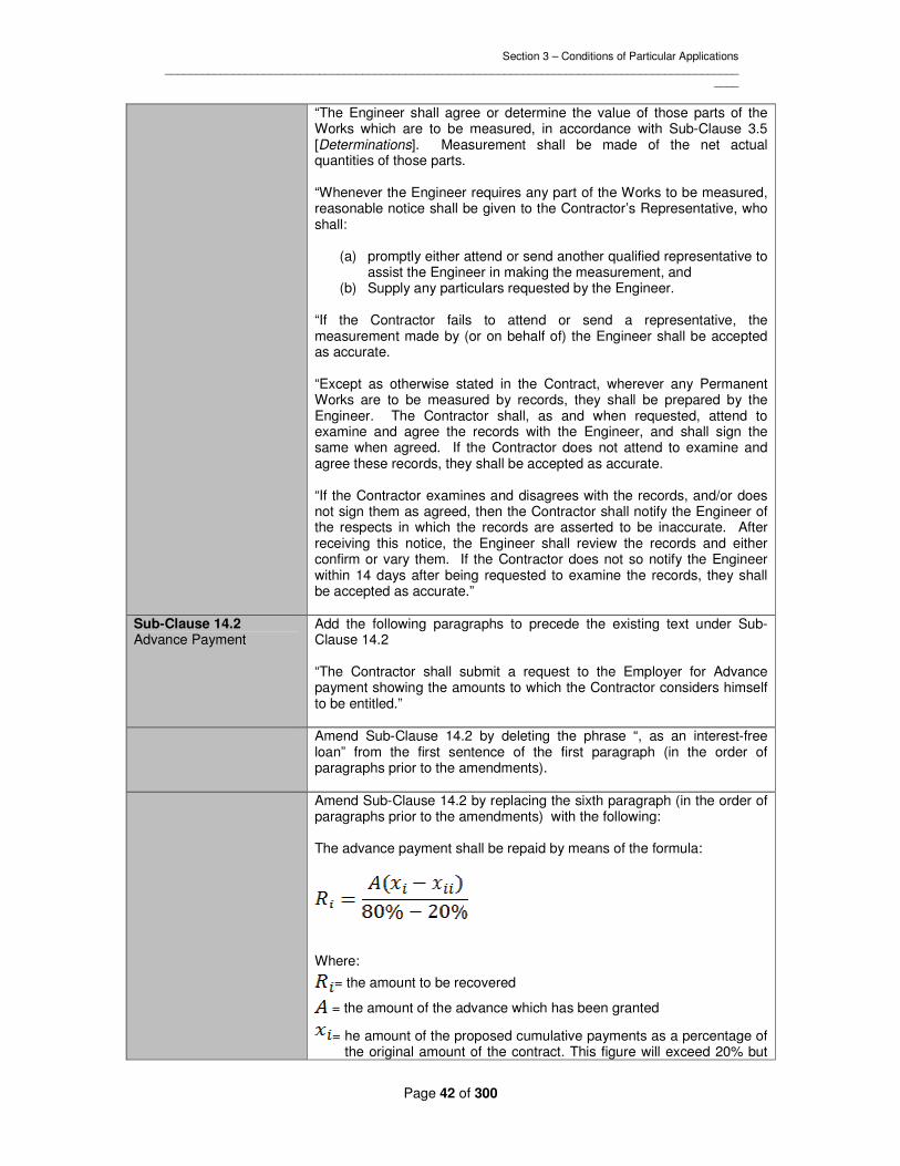
Section 3 – Conditions of Particular Applications _____________________________________________________________________________________________
____
Page 42 of 300
“The Engineer shall agree or determine the value of those parts of the Works which are to be measured, in accordance with Sub-Clause 3.5 [Determinations]. Measurement shall be made of the net actual quantities of those parts. “Whenever the Engineer requires any part of the Works to be measured, reasonable notice shall be given to the Contractor’s Representative, who shall:
(a) promptly either attend or send another qualified representative to assist the Engineer in making the measurement, and
(b) Supply any particulars requested by the Engineer. “If the Contractor fails to attend or send a representative, the measurement made by (or on behalf of) the Engineer shall be accepted as accurate. “Except as otherwise stated in the Contract, wherever any Permanent Works are to be measured by records, they shall be prepared by the Engineer. The Contractor shall, as and when requested, attend to examine and agree the records with the Engineer, and shall sign the same when agreed. If the Contractor does not attend to examine and agree these records, they shall be accepted as accurate. “If the Contractor examines and disagrees with the records, and/or does not sign them as agreed, then the Contractor shall notify the Engineer of the respects in which the records are asserted to be inaccurate. After receiving this notice, the Engineer shall review the records and either confirm or vary them. If the Contractor does not so notify the Engineer within 14 days after being requested to examine the records, they shall be accepted as accurate.”
Sub-Clause 14.2 Advance Payment
Add the following paragraphs to precede the existing text under Sub-Clause 14.2 “The Contractor shall submit a request to the Employer for Advance payment showing the amounts to which the Contractor considers himself to be entitled.”
Amend Sub-Clause 14.2 by deleting the phrase “, as an interest-free loan” from the first sentence of the first paragraph (in the order of paragraphs prior to the amendments).
Amend Sub-Clause 14.2 by replacing the sixth paragraph (in the order of paragraphs prior to the amendments) with the following: The advance payment shall be repaid by means of the formula:
Where:
= the amount to be recovered
= the amount of the advance which has been granted
= he amount of the proposed cumulative payments as a percentage of the original amount of the contract. This figure will exceed 20% but

Section 3 – Conditions of Particular Applications _____________________________________________________________________________________________
____
Page 43 of 300
not exceed 80%. .
= the amount of the previous cumulative payments as a percentage of the original amount of the contract. This figure will be below 80% but not less than 20%.
Amend Sub-Clause 14.2 by inserting the following after “become due” in
the final sentence: “and in the case of termination under Clause 15 [Termination by Employer] or Sub-Clause 19.6 [Optional Termination, Payment and Release], ”
Sub-Clause 14.7 Payment
Amend Sub-Clause 14.7 by replacing the first line with the following: “The Employer shall pay or cause to be paid to the Contractor:”
Sub-Clause 14.8 Delayed Payment
Amend Sub-Clause 14.8 by replacing the second paragraph with the following: “These financing charges shall be calculated at the annual rates of interest and shall be paid in the currencies indicated in the Appendix to Bid.”
Sub-Clause 14.9 Payment of Retention Money
Amend Sub-Clause 14.9 by adding the following at the end: “When the Taking-Over Certificate has been issued for the Works and the first half of the Retention Money has been certified by the Engineer for payment, the Contractor shall be entitled to substitute a guarantee, in the form annexed to the Particular Conditions or in another form approved by the Employer and provided by an entity approved by the Employer, for the second half of the Retention Money. The Contractor shall ensure that the guarantee is in the amounts and currencies of the second half of the Retention Money and is valid and enforceable until the Contractor has executed and completed the Works and remedied any defects, as specified for the Performance Security in Sub-Clause 4.2 [Performance Security]. On receipt by the Employer of such guarantee, the Engineer shall certify and the Employer shall pay, or cause to be paid, the second half of the Retention Money. The release of the second half of the Retention Money against such guarantee shall then be in lieu of the release under the second paragraph of this Sub-Clause. The Employer shall return the guarantee to the Contractor within 21 days after receiving a copy of the Performance Certificate. “If the Performance Security required under Sub-Clause 4.2 [Performance Security] is in the form of a demand guarantee, and the amount guaranteed under it when the Taking-Over Certificate is issued is more than half of the Retention Money, then the Retention Money guarantee will not be required. If the amount guaranteed under the Performance Security when the Taking-Over Certificate is issued is less than half of the Retention Money, the Retention Money guarantee will only be required for the difference between half of the Retention Money and the amount guaranteed under the Performance Security.”
Sub-Clause 14.11 Application for Final Payment Certificate
Amend Sub-Clause 14.11 by inserting the following in the first sentence of the second paragraph after “may reasonably require”: “within 28 days from request of the Engineer’”

Section 3 – Conditions of Particular Applications _____________________________________________________________________________________________
____
Page 44 of 300
16. Suspension and Termination by Contractor
Sub-Clause 16.2 Termination by Contractor
Amend Subpara. (d) of Sub-Clause 16.2 by adding the following at the end: “in such manner as to materially and adversely affect the economic balance of the Contract and/or the ability of the Contractor to perform the Contract,”
Amend Subpara. (f) of Sub-Clause 16.2 by deleting the word “or” at the end.
Amend Subpara, (g) of Sub-Clause 16.2 by replacing the period at the end with “; or”.
Amend Sub-Clause 16.2 by adding the following at the end of the first paragraph: ”(h) the Contractor does not receive the Engineer’s instruction recording
the agreement of both Parties on the fulfillment of the conditions for the commencement of Works under Sub-Clause 8.1 [Commencement of Works].”
17. Risk and Responsibility
Sub-Clause 17.3 Employer’s Risks
Amend Sub-Clause 17.3 by replacing the first line with the following: “The Employer’s risks, insofar as they directly affect the design and execution of the Works,”
Sub-Clause 17.6 Limitation of Liability
Amend Sub-Clause 17.6 by replacing the first paragraph with the following: “Neither Party shall be liable to the other Party for loss of use of any Works, loss of profit, loss of any contract or for any indirect or consequential loss or damage which may be suffered by the other Party in connection with the Contract, other than as specifically provided in Sub-Clause 8.7 [Delay Damages]; Sub-Clause 11.2 [Cost of Remedying Defects]; Sub-Clause 15.4 [Payment after Termination]; Sub-Clause 16.4 [Payment on Termination]; Sub-Clause 17.1 [Indemnities]; Sub-Clause 17.4 (b) [Consequences of Employer’s Risks] and Sub-Clause 17.5 [Intellectual and Industrial Property Rights].”
18. Insurance
Sub-Clause 18.1 General Requirements for Insurance
Amend Sub-Clause 18.1 by adding the following at the end: “The insuring Party shall be entitled to place all insurance relating to the Contract (including, but not limited to the insurance referred to in Clause 18 [Insurance]) with insurers from any eligible source country unless otherwise stated in the Appendix to Bid.”
Sub-Clause 18.5 Insurance for Design
Add the following Sub-Clause 18.5: “The Contractor shall effect professional indemnity insurance which shall cover the risk of professional negligence in the design of the Works. This insurance shall be for a limit of not less than the amount stated in the Appendix to Bid, with no limit on the number of occurrences. The Contractor shall maintain the professional indemnity insurance in full

Section 3 – Conditions of Particular Applications _____________________________________________________________________________________________
____
Page 45 of 300
force and effect until 5 years after the Time for Completion. The Contractor undertakes to notify the Employer promptly of any difficulty in extending, renewing or reinstating this insurance.”
19. Force Majeure
Sub-Clause 19.4 Consequences of Force Majeure
Amend Sub-Clause 19.4 by inserting the following at the end of Subpara. (b): “, including the costs of rectifying or replacing the Works and/or Goods damaged or destroyed by Force Majeure, to the extent they are not indemnified through the insurance policy referred to in Sub-Clause 18.2 [Insurance for Works and Contractor’s Equipment].”
20. Claims, Disputes and Arbitration
Sub-Clause 20.1 Contractor’s Claims
Amend Sub-Clause 20.1 by inserting the following as a new paragraph between subparagraphs 6 and 7: “Within the above defined period of 42 days, the Engineer shall proceed in accordance with Sub-Clause 3.5 [Determinations] to agree or determine (i) the extension (if any) of the Time for Completion (before or after its expiry) in accordance with Sub-Clause 8.4 [Extension of Time for Completion], and/or (ii) the additional payment (if any) to which the Contractor is entitled under the Contract.”
Amend Sub-Clause 20.1 by deleting paragraph 8 (in the order of paragraphs prior to the amendment made above) and replacing it with the following new paragraph: “If the Engineer does not respond within the timeframe defined in this Sub-Clause, either Party may consider that the claim is rejected by the Engineer and either Party may refer such claim to the DAB in accordance with Sub-Clause 20.4 [Obtaining Dispute Adjudication Board’s Decision].”
Sub-Clause 20.2 Appointment of the Dispute Adjudication Board
Amend Sub-Clause 20.2 by inserting the following at the end of the first sentence of the second paragraph: “, each of whom shall be fluent in the language for communication defined in the Contract and shall be a professional experienced in the type of construction involved in the Works and with the interpretation of contractual documents.”
Sub-Clause 20.6 Arbitration
Amend Sub-Clause 20.6 by replacing the first paragraph with the following: “Any dispute not settled amicably and in respect of which the DAB’s decision (if any) has not become final and binding shall be finally settled by arbitration. Unless otherwise agreed by both Parties, the dispute shall be referred to the competent court of Kenya or for Arbitration under Kenyan Laws.
Section 4. Employer’s Requirements _____________________________________________________________________________________________
____
Page 46 of 300
Section 4. Employer’s Requirements

Section 4. Employer’s Requirements _____________________________________________________________________________________________
____
Page 47 of 300
Ndarugu 1 Dam Water Scheme
Introduction
The proposed Water Supply Scheme involves construction of 35m High Dam as proposed in the Nairobi Water Master Plan, raw water and treated water transmission through pumping. Raw water transmission will involve pumping of water from the dam to a proposed water treatment site located approximately 1km from the dam. The treated water transmission will involve pumping of water from the proposed treatment site to Utawala reservoir via a pipeline of approximate length 30Km. About 50,000m3/d of water will be distributed to serve parts of Nairobi lower than 1550 which include Ruai among others while the rest will be boosted to existing Ring Road Tank (35,000m3/d), proposed Embakasi Tank (38,000m3/d) and proposed Syokimau Tank (50,000m3/d). Water distribution from the existing and proposed tanks will then be by gravity to the demand areas.
In brief, the proposed Ndarugu 1 Dam Water Supply Scheme will involve construction of the following works:
• Ndarugu 1 Dam on Ndarugu River approx. 1Km upstream of the confluence with Komu River
• Raw Water Pumping Station at Ndarugu 1 Dam Outlet Works
• Raw Water Pumping Main of approximate length of 1Km from Ndarugu 1 Dam to a Proposed Water Treatment Site
• Water Treatment Works, capacity 173,000m3/d
• Treated Water Pumping Station at the proposed Water Treatment Site, capacity 173,000m3/d
• Treated Water Pumping Main of approximate length of 30Km from the Pumping Station to Utawala Tank, capacity 173,000m3/d
• Treated Water Pumping Main of approximate length of 13Km from Utawala Tank to Ring Road Tank, capacity 35,000m3/d
• Treated Water Pumping Main of approximate length of 6Km from Utawala Tank to Embakasi Tank, capacity 38,000m3/d
• Treated Water Pumping Main of approximate length of 14Km from Utawala Tank to Syokimau Tank, capacity 50,000m3/d
• Treated water pumping main of approximate length of 40Km from Utawala Tank to Koma Tank, capacity 25,000m3/d
• Utawala, Embakasi, Syokimau, Mavoko, & Koma Tanks
• Distribution Mains from Syokimau Reservoir to Syokimau/Mlolongo, Athi River and Kitengela areas.
• Distribution Mains from Koma Reservoir to Nguluni, Tala and Kangundo town.
A layout plan showing the proposed Ndarugu 1 Water Supply Scheme to Nairobi and Mavoko-Kitengela area and the existing water transmission systems is given in Figure 8.1.

Section 4. Employer’s Requirements _____________________________________________________________________________________________
____
Page 48 of 300
Dam Characteristics
The dam optimal maximum height is proposed to be 35m high Roller Compacted Concrete Dam with a reservoir storage volume of approximately 225 Million m3. The impoundment area at maximum dam height is approximately 14.5 Km2 (1450 Ha).
The construction of the Ndarugu 1 dam is expected to involve the works given in Table 8.4. Table 8.4: Estimated Works for Ndarugu 1 Dam
Item Unit Quantity
Soft Excavation m3 150,000 Rock fill or Roller Compacted Concrete
m3 400,000
Curtain Grouting m 1000 Draw-off works, River Diversion among to the works

Section 4. Employer’s Requirements _____________________________________________________________________________________________
____
Page 49 of 300
Figure 8.1: Layout Plan – Ndarugu 1 Scheme
Raw Water Transmission
The raw water transmission from Ndarugu 1 Dam to the water treatment works will comprise of Raw Water Pumping Station and a DN1200 Pumping Main. The raw water pumping station will be sited at the dam outlet works at the foot of the dam. The pumping station will include 100% stand-by capacity and the pump characteristics will be as follows:
• Pumping rate - 7,200 m3/hr • Head on Pumps - 47.2 m • Power - 1,558 Kw
The hydraulics constraints of the raw water transmission system are summarised in Table 8.5 below.
Table 8.5: Raw Water Transmission – Hydraulic Constraints and Optimisation
Parameters Ndarugu 1 Dam Water Treatment Works
Approximate Ground Elevation - 1425 masl 1465 masl
Static Lift - 40 m
Approximate Distance - 1.0 Km
Design Capacity - 173,000 m3/d
Pipeline Diameter - 1200 mm
Nominal Pressure Rating - 10 bar
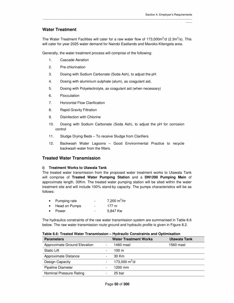
Section 4. Employer’s Requirements _____________________________________________________________________________________________
____
Page 50 of 300
Water Treatment
The Water Treatment Facilities will cater for a raw water flow of 173,000m3/d (2.3m3/s). This will cater for year 2025 water demand for Nairobi Eastlands and Mavoko-Kitengela area.
Generally, the water treatment process will comprise of the following:
1. Cascade Aeration
2. Pre-chlorination
3. Dosing with Sodium Carbonate (Soda Ash), to adjust the pH
4. Dosing with aluminium sulphate (alum), as coagulant aid,
5. Dosing with Polyelectrolyte, as coagulant aid (when necessary)
6. Flocculation
7. Horizontal Flow Clarification
8. Rapid Gravity Filtration
9. Disinfection with Chlorine
10. Dosing with Sodium Carbonate (Soda Ash), to adjust the pH for corrosion control
11. Sludge Drying Beds – To receive Sludge from Clarifiers
12. Backwash Water Lagoons – Good Environmental Practice to recycle backwash water from the filters.
Treated Water Transmission
i) Treatment Works to Utawala Tank
The treated water transmission from the proposed water treatment works to Utawala Tank will comprise of Treated Water Pumping Station and a DN1200 Pumping Main of approximate length, 30Km. The treated water pumping station will be sited within the water treatment site and will include 100% stand-by capacity. The pumps characteristics will be as follows:
• Pumping rate - 7,200 m3/hr • Head on Pumps - 177 m • Power - 5,847 Kw
The hydraulics constraints of the raw water transmission system are summarised in Table 8.6 below. The raw water transmission route ground and hydraulic profile is given in Figure 8.2.
Table 8.6: Treated Water Transmission – Hydraulic Constraints and Optimisation
Parameters Water Treatment Works Utawala Tank
Approximate Ground Elevation - 1460 masl 1560 masl
Static Lift - 100 m
Approximate Distance - 30 Km
Design Capacity - 173,000 m3/d
Pipeline Diameter - 1200 mm
Nominal Pressure Rating - 25 bar

Section 4. Employer’s Requirements _____________________________________________________________________________________________
____
Page 51 of 300
A preliminary pipeline route has been identified for conceptual design purposes. The most convenient pipeline route will be determined at the detailed design stage to avoid disruption of private property and farmlands and also to avoid engineering difficulties. Generally, the proposed pipeline will traverse across developed areas of Ruai and Utawala.
The pipeline has been routed to cross Nairobi river after the confluence with Ruiru and Thiririka rivers. The pipeline will then run along the southern edge of Nairobi river close to Ruai sewage works before joining the Eastern Bypass road to Utawala.
1400
1450
1500
1550
1600
1650
1700
0 5 10 15 20 25 30
Ele
va
tio
n m
asl
Distance, Km
Ground Profile
Hydraulic Gradient Line
Ndarugu Pumping
Station
Nairobi River
crossing
Utawala
Reservoir
Figure 8.2: Transmission Route Profile - Water Treatment Works to Utawala
Reservoir
ii) Utawala Tank to Ring Road Tank
The treated water transmission from the proposed Utawala Tank to Ring Road Tank will comprise of Treated Water Pumping Station and a DN700 Pumping Main of approximate length, 30Km. The treated water pumping station will be sited within the water treatment site and will include 100% stand-by capacity. The pumps characteristics will be as follows:
• Pumping rate - 1,458 m3/hr • Head on Pumps - 98 m • Power - 646 Kw
The hydraulics constraints of the water transmission pipeline are summarised in Table 8.7 below. The raw water transmission route ground and hydraulic profile is given in Figure 8.3.

Section 4. Employer’s Requirements _____________________________________________________________________________________________
____
Page 52 of 300
Table 8.7: Treated Water Transmission – Hydraulic Constraints and Optimisation
Parameters Utawala Tank Ring Road Tank
Approximate Ground Elevation - 1560 masl 1630 masl
Static Lift - 70 m
Approximate Distance - 13 Km
Design Capacity - 35,000 m3/d
Pipeline Diameter - 700 mm
Nominal Pressure Rating - 25 bar
A preliminary pipeline route has been identified for conceptual design purposes. Generally, the proposed pipeline will traverse across developed areas of Utawala, Mihango, Njiru, Komarock, Kayole, Umoja and Donholm. The pipeline will run along Kangundo Road, Kayole spine Road Mananja Road and a short section of Outering Road. The exact pipeline alignment will be determined at the detailed design stage to minimise disruption of private property.
1500
1520
1540
1560
1580
1600
1620
1640
1660
1680
0 2 4 6 8 10 12 14
Ele
va
tio
n m
asl
Distance, Km
Ground Profile
Hydraulic Gradient Line
Utawala Pumping
Station
Ring Road
Reservoir
Figure 8.3: Transmission Route Profile – Utawala Tank to Ring Road Tank
iii) Utawala Tank to Embakasi Tank
The treated water transmission from the proposed Utawala Tank to Embakasi Tank will comprise of Treated Water Pumping Station and a DN700 Pumping Main of approximate length, 6Km. The treated water pumping station will be sited within the water treatment site and will include 100% stand-by capacity. The pumps characteristics will be as follows:
• Pumping rate - 1,584 m3/hr • Head on Pumps - 81 m • Power - 586 Kw

Section 4. Employer’s Requirements _____________________________________________________________________________________________
____
Page 53 of 300
The hydraulics constraints of the water transmission pipeline are summarised in Table 8.8 below. The water transmission route ground and hydraulic profile is given in Figure 8.4.
Table 8.8: Treated Water Transmission – Hydraulic Constraints and Optimisation
Parameters Utawala Tank Embakasi Tank
Approximate Ground Elevation - 1560 masl 1620 masl
Static Lift - 60 m
Approximate Distance - 6 Km
Design Capacity - 38,000 m3/d
Pipeline Diameter - 700 mm
Nominal Pressure Rating - 25 bar
The pipeline route is proposed to run along the Eastern Bypass Road.
1550
1560
1570
1580
1590
1600
1610
1620
1630
1640
1650
0 1 2 3 4 5 6
Ele
va
tio
n m
asl
Distance, Km
Ground Profile
Hydraulic Gradient Line
Utawala Pumping
Station
Embakasi
Reservoir
Figure 8.4: Transmission Route Profile – Utawala Tank to Embakasi Tank
iv) Utawala Tank to Syokimau Tank
The treated water transmission from the proposed Utawala Tank to Syokimau Tank will comprise of Treated Water Pumping Station and a DN800 Pumping Main of approximate length, 14.5Km. The treated water pumping station will be sited within the water treatment site and will include 100% stand-by capacity. The pumps characteristics will be as follows:
• Pumping rate - 2,083 m3/hr • Head on Pumps - 98 m • Power - 938 Kw

Section 4. Employer’s Requirements _____________________________________________________________________________________________
____
Page 54 of 300
The hydraulics constraints of the water transmission pipeline are summarised in Table 8.9 below. The water transmission route ground and hydraulic profile is given in Figure 8.4.
Table 8.9: Treated Water Transmission – Hydraulic Constraints and Optimisation
Parameters Utawala Tank Syokimau Tank
Approximate Ground Elevation - 1560 masl 1630 masl
Static Lift - 70 m
Approximate Distance - 14.5 Km
Design Capacity - 50,000 m3/d
Pipeline Diameter - 800 mm
Nominal Pressure Rating - 25 bar
The pipeline is proposed to cut across Utawala after which it will run along the South-Eastern boundary of Jomo Kenyatta International Airport along Syokimau-Airport Road. The pipeline then follows the road up to Mombasa Road and to the proposed Syokimau Tank site.
1550
1560
1570
1580
1590
1600
1610
1620
1630
1640
1650
0 2 4 6 8 10 12 14
Ele
va
tio
n m
asl
Distance, Km
Ground Profile
Hydraulic Gradient Line
Utawala Pumping
Station
Syokimau
Reservoir
Figure 8.4: Transmission Route Profile – Utawala Tank to Syokimau Tank

Section 4. Employer’s Requirements _____________________________________________________________________________________________
____
Page 55 of 300
v) Utawala Tank to Koma Tank
The treated water transmission from the proposed Utawala Tank to Koma Tank will comprise of Treated Water Pumping Station and a DN300 Pumping Main of approximate length, 40Km. The treated water pumping station will be sited within the water treatment site and will include 100% stand-by capacity. The pumps characteristics will be as follows:
• Pumping rate - 1,041 m3/hr • Head on Pumps - 180 m • Power - 1560 Kw
The hydraulics constraints of the water transmission pipeline are summarised in Table 8.10 below.
Table 8.10: Treated Water Transmission – Hydraulic Constraints and Optimisation
Parameters Utawala Tank Koma Hill Tank
Approximate Ground Elevation - 1560 masl 1588 masl
Static Lift - 28 m
Approximate Distance - 40 Km
Design Capacity - 25,000 m3/d
Pipeline Diameter - 300 mm
Nominal Pressure Rating - 25 bar
The pipeline is proposed to follow Kangundo Road up to Koma market and divert to the proposed Tank site at Koma Hill and then follows the road again passing through Tala town and terminates at Kangundo town

Section 5. Technical Specifications _____________________________________________________________________________________________
____
Page 56 of 300
Section 5. Technical Specifications

Section 5. Technical Specifications _____________________________________________________________________________________________
____
Page 57 of 300
SPECIFICATION INDEX SECTION 1 GENERAL SECTION 2 EARTHWORKS SECTION 3 CONCRETE SECTION 4 UNDERGROUND WORKS SECTION 5 SITE INVESTIGATIONS SECTION 6 FOUNDATION TREATMENTS SECTION 7 PIPES AND VALVES SECTION 8 BUILDING WORK SECTION 9 FENCING SECTION 10 DRAINAGE SESTION 11 STRUCTURAL STEEL WORK SECTION 12 PAINTING SECTION 13 ELECTRICAL AND MECHANICAL PLANTS

Section 5. Technical Specifications _____________________________________________________________________________________________
____
Page 58 of 300
SPECIFICATION 1 – GENERAL INDEX SCOPE AND LOCATION OF THE WORKS Location Of Use Works Access Roads Permanent Access Roads Temporary Access Roads Restrictions on use of Roads Maintenance GEOTECHNICAL INFORMATION CONTRACT DRAWINGS General Construction Details and Modification For Electrical and Mechanical Plant Record Drawings LEVEL DATUM LEVELS, DIMENSIONS AND SETTING OUT BOUNDARIES OF WORKS ACCOMMODATION, OFFICES, INSTRUMENT AND FACILITIES FOR ENGINEERING’S REPRESENTATIVE General Telephones, Water and Electricity Etc Labour and Materials Radios Vehicles Other Contracts CONTRACTOR’S STAFF, COMMUNICATION, OFFICES, ETC General Language Of Correspondence And Records Contractor’s Duty Staff And Offices Public Relations Contractor’s Yards, Stores, Etc ACCOMMODATION FOR WORKMEN DEMOLITION OF CONTRACTOR’S TEMPORARY BUILDINGS MEDICAL SERVICES 112.1 CLINIC 112.2 FIRST AID OUTFITS/ AMBULANCES 112.3 MEDICAL SERVICES AVAILABLE FOR ENGINEERS’S STAFF 113 PROTECTIVE CLOTHING 114 PRECAUTION AGAINST CONTAMINATION OF THE WORK 115 TEMPORARY WATER AND ELECTRICITY SUPPLY 115.1 Water 115.2 Electricity 116 INSPECTION BY ENGINEER DURING PERIOD AND OF DEFICITS LIABILITY 117 ADVERTISEMENTS 118 STANDARDS AND REGULATIONS 119 SAMPLES 119.1 General 119.2 Responsible For Ordering Materials And

Section 5. Technical Specifications _____________________________________________________________________________________________
____
Page 59 of 300
Manufactured Articles And Sample For Testing Tests Of Materials And Manufacturedarticles Before Use Facilities For Engineer’s Representative To Take Samples 120 MATERIALS TESTING LABORATORY 121 QUALITY OF MATERIALS AND WORKMANSHIP 121.1 General 121.2 Rejected Materials 121.3 Quality Control 122 Existing Services and Installation 122.1 General 122.2 Temporary Removal of Existing Services 122.3 Permanent Diversion of Existing Services 122.4 Permanent Support for Existing Services, Etc Authority Or Owners May Carry Out Work Of Repairs, Etc 122.6 Care Of Boundary Walls And Fences 123 WORK THROUGH PRIVATE AND PUBLIC PROPERTY AND SERVING OF NOTICES 124 CONTROL OF WATER 124.1 Responsibilities of The Contractor 124.2 Design River Flow 124.3 River Diversion during Construction 125 Impounding 126 DEWATERING FOUNDATION

Section 5. Technical Specifications _____________________________________________________________________________________________
____
Page 60 of 300
SECTION 1 – GENERAL SC0PE AND LOCATION OF THE WORKS Description of the Works and program As described in the Employers requirement The contract program requires completion of the works within three (3) years from the date of handing over site. Location of the works (As described in the Employes Requirement) ACCESS ROADS Permanent Access Roads The contractor shall construct access roads to the permanent works following the routes shown on the drawings, to designs prepared by the contractor and approved by the engineer. At the end of the contract those roads shall be renovated to the permanent standard as specified. The contractor shall also improve existing tracks to the standard necessary to allow him all-weather access to the works. Those roads will also be renovated on completion of the works to the permanent standard specified. Temporary Access Roads The contractor shall access his own need for access roads to the temporary site installation and to quarries, borrow pits and spoil tips and shall construct such roads at his own expense. Restrictions on Use of Roads The contractor shall not run tracked vehicles or tracked plant on any public or private road without the written approval of the Engineer and the responsible authority or owner and subject to such conditions as each may reasonably require. The contractor shall observe all weight and dimensions restrictions which apply to roads and tracks in Kenya and he shall comply with all reasonable restrictions which may from time to time be imposed by the Engineer, Employer, Police, responsible authority or owner. Where damage to roads and track is caused by the contractor, this shall be repaired at the contractor’s expense. In particular the contractor shall fill potholes in roads with road stone when these are deepened by his plant. The Engineer shall have the power to restrict the contractor’s use of any roads, either in direction of traffic, speed of traffic or numbers of vehicles in order to preserve such roads or to make such roads safe for use by the general public. Where other contractors require the use of these roads or tracks, the engineer may prescribe times of usage, or any other form of control, which shall be executed by the contractor, including the supply of traffic lights, flagmen, or any other thing. Maintenance

Section 5. Technical Specifications _____________________________________________________________________________________________
____
Page 61 of 300
The contractor shall maintain all access roads throughout the duration of the contract so that they are open to traffic at all times. 103 GEOTECHNICAL INFORMATION A geotechnical investigation comprising cored boreholes, trial pits and in situ and laboratory testing SHALL BE carried out at the site upstream of the dam, subject to the approval of the Engineer. The cost of these exploration shall be included in the consultancy for the design and build. CONTRACT DRAWINGS 104.1 General The Contractor shall prepare the preliminary drawings based on conceptual Drawings and submit them to the Engineer for Approval. Upon Approval the Contractor Shall proceed to prepare detailed Drawings Further Construction Drawings shall be issued by the contractor and approved by the Engineer from time to time in accordance with the conditions of contract. Any drawings which are submitted by the contractor to further describe the permanent works and which are approved by the Engineer shall become contract drawings upon the issue of such drawings shall be the responsibility of the contractor. Construction Details and Modifications for Electrical and Mechanical Plant. Where the main contractor is also the supplier of electrical and/or mechanical plant, it shall be his responsibility to provide building and civil engineering construction details to suit all plant, equipment and fittings of any sort whatever supplied under the contract. Such details including general fixing arrangements, concrete details with box-outs and pockets shall be to the approval of the engineer. Record Drawings As the work proceeds the contractor shall mark up “as-built” details on a set of prints of the contract Drawings modified to portray the work as actually constructed, and issue such drawings to the Engineer for approval within two weeks of completion of the works covered by each drawing. The contractor shall similarly provide record drawings of all electrical and mechanical equipment supplied and installed under the contract. Drawings shall be supplemented as necessary by schedules, data sheets, etc. LEVEL DATUM All levels are referred to Kenyan Ordnance Datum and the contractor shall obtain in writing from the Engineer the location and value of the permanent bench marks to be used. Before the commencement of constructional work the contractor shall establish at each site in a position to the approval of the Engineer, a steel datum peg which shall be securely concreted in. The level of this peg shall be established and agreed with the Engineer and all levels used in the construction of the works shall be referred to this established datum. The correctness of this established datum shall be checked at regular in intervals during the construction period as agreed with the Engineer.

Section 5. Technical Specifications _____________________________________________________________________________________________
____
Page 62 of 300
LEVELS, DIMENSIONS AND SETTING OUT The levels of the ground and the levels and dimensions of existing features shown on the Drawings are believed but are not guaranteed to be correct. In the event of any discrepancies the contractor shall notify the Engineer in writing immediately, together with corrected dimensions levels or positions within two days. Wherever dimensions or levels are marked on the Drawings such dimensions or levels shall take precedence over dimensions scaled from the Drawings. Large scale Drawings shall be taken in preference to Drawings of smaller scale. BOUNDARIES The Employer will provide land on which the Permanent Works included in the contract are to be constructed. The contractor shall be given possession of such parts of the site that he requires; provided his operations do not interfere with other contractors, he shall be given the whole of the site. Where a drain or pipeline is to be within an existing road reservation the contractor’s working width will be restricted. The existing boundary fences and walls shall not be disturbed without the prior approval of the Engineer’s Representative and the carriageway shall be left available to traffic. The contractor shall not enter upon or occupy with men, tools, equipment and materials any land other than land or rights of way provided by the Employer without the written consent of the owner of such land. The contractor shall provide temporary fencing or immediately install permanent fencing where such is required. Where the permanent works do not include fencing (drains and pipelines etc) the contractor shall submit his proposals to the Engineer as to how he intends to fulfill his obligations under the contract which shall be to the approval of the Engineer. The contractor shall be responsible for watching and lighting the works and for the flagging and control traffic and he shall comply with the requirements of the Employer and police and the competent Authority in these matters. 108 ACCOMMODATION, OFFICES, INSTRUMENTS AND FACILITIES FOR FOR ENGINEER’S REPRESENTATIVE 108.1 General The contractor shall maintain the accommodation, offices, services and instruments described herein The contractor will be instructed in writing by the Engineer the date from which such maintenance shall commence. Additional equipment and instruments shall be provided complete before any construction commences and shall be maintained to the satisfaction of the Engineer’s Representative throughout the duration of the contract. Telephones, Water and Electricity Etc. The contractor shall be responsible for providing all the temporary services including gas, telephones, electricity and portable water as may be required. The contractor shall also ensure that the offices are cleaned every day and guarded at night. Labour and Material

Section 5. Technical Specifications _____________________________________________________________________________________________
____
Page 63 of 300
The contractor shall make available such labour and materials as the Engineers Representative may require for survey work in connection with the works. The contractor shall provide at his own expense any necessary tackle, test equipment, access, labour, staff and any other thing the Engineer’s Representative may reasonably require in order that he may conveniently and quickly carry out such inspections as he deems necessary at any time during the contract. Radios The contractor shall maintain the 168.6 MHZ mobile radio sets and ancillary equipment from a date to be instructed by the Engineer in writing. Vehicles The contractor shall maintain vehicles provided under which shall be for the sole use of the Engineer and his staff. The contractor will be instructed in writing by the Engineer the date from which such maintenance shall commence. The contractor shall pay for all the expenses incurred in the operation of such vehicles which shall include any taxation, licenses, fuels, oils, services, spares including tyres, comprehensive insurance including alternative transport should the vehicle be in any way out of use. Reimbursement shall be against the appropriate item of the bill of quantities. The contractor shall make available such drivers as are required by the Engineer’s Representative or his staff for the satisfactory operation of such vehicles, and where directed by the Engineer’s Representative shall provide such security arrangements as he deems necessary. Reimbursement shall be against the appropriate item of the bill of quantities. Other Contracts. The employer has entered or will enter into other contracts in connection with the scheme of which the works form a part. The accommodation and offices (including the supply of electricity and water), vehicles and equipment supplied under this contract shall be used by the Engineer and his staff also for the supervision of these other contracts. CONTRACTOR’S STAFF, COMMUNICATION, OFFICES, ETC General The contractor shall advise the Engineer at which of his offices any notices may be served. Language of Correspondence and Records All communications from the contractor to the Engineer and the Engineer’s Representative shall be in the English language. All books, time sheets, records, notes, drawings, documents, specifications and manufacturers’ literature etc shall be in the English language. If any of the aforementioned be in another language a certified translation in English shall be submitted to the Engineer or his Representative. Contractor’s Duty Staff and Offices At least one responsible senior representative of the contractor shall be immediately available at all times and he shall be on the site during normal working hours. To such representative shall be delegated fully authority to confer with the Engineer’s Representative or his Deputy to take all steps and to issue all those instructions which may be required in an emergency to ensure the safety of all personnel of the works and of all the

Section 5. Technical Specifications _____________________________________________________________________________________________
____
Page 64 of 300
Employers and other property on the site and in the immediate vicinity thereof. The Engineer’s Representative may from time to time at his discretion after taking into consideration all the prevailing conditions, allow some relaxation of this clause but such relaxation shall be made only with his written permission and subject to any special condition which he may then require. The contractor shall provide and maintain at the site, offices for the use of his representative and to which written instructions by the Engineer’s Representative can be delivered. Any instructions delivered to such offices shall be deemed to have been delivered to the contractor. Public Relations The contractor shall designate within his site organization competent staff whose responsibility shall be to ensure good public relations. Contractor’s Yards, Stores Etc The contractor shall make his own arrangements for all land, yards, stores, workshops, offices, etc and for all services in connection therewith. The location of all yards, stores, workshop offices etc and for services in connection therewith. The location of all yards, stores, workshop, offices etc shall be agreed before hand with the Engineer’s representative and shall be such as to avoid obstruction and nuisance to the public. The contractor shall provide and maintain at or near the site suitable and sufficient shelter, mess rooms, wash rooms latrines etcetera, as necessary and customary, to the satisfaction of the engineer and in accordance with the laws and regulations of the local Authority 110 ACOMMODATION FOR WORKMEN Where the contractor wishes to construct a camp to accommodate his labour the following shall be also be subjected to the requirement of the labour ordinances of Kenya and any other requirement made by the district or provincial Administration or any County Government. Adequate arrangement shall be made. The proper disposal of all the refuse. A supply of potable and domestic water not less than 90 liters per head per day for labour resident in the camp with an adequate number of storage tanks maintained in a hygienic conditions. The storage of food in hygienic conditions in building with raised floors. Maintaining the camps at times in a clean conditions to the satisfaction of the medical officer of health of Nairobi Commission (here in after referred to as the medical of health The control and extermination of the all rats and vermin. Such control and exercised in conjunction and co-operation with the medical officer of health. The disposal without nuisance of all storm and surface water and waste water from latrines, kitchens and storage tanks. The maintenance of all tent age buildings and works in a proper and satisfactory state of repair. The inspection by a responsible supervisor at least once daily of all labour camps. Adequate fire fighting equipment. All camps sites which the contractor may erect shall conform to the following requirements:-

Section 5. Technical Specifications _____________________________________________________________________________________________
____
Page 65 of 300
The space between any two tents or buildings shall not be less than 3 meters and in general there shall be 6 meters between rows of tents or buildings and between tents or buildings and the camp boundary. All walls and roofs shall be water proof and thatch or similar materials shall not be used. The floor shall be firm and even at least 0.1m above the level of the adjoining ground, floors should generally slope towards the door. Adequate means of permanent ventilation shall be provided. Fires shall be prohibited in sleeping quarters. Latrines shall be provided at the rate of one seat or aperture for every 15 persons. Such latrines shall be of the deep pit type and shall be constructed of corrugated iron or other approved material and each compartment shall not be less than 1sq. meter in area and in addition they shall: Be conveniently sited and not nearer than 15 meters from the nearest camp building. Have the aperture sited over a hole not less than 6 meters deep. Be adequately fly-proofed. or as otherwise approved by the Engineer’s Representative. A room or building shall be provided for the drying of clothes. Such room or building shall be equipped with heating and ventilating arrangements and facilities adequate for hanging up and drying clothes for all labourers employed on the site. The users of the drying room or building shall be controlled in an orderly manner and every precaution shall be taken against theft and disturbances. The contractor shall at all times exercise a proper and adequate control of all labour camps and shall provide and install such lighting as may be necessary to exercise such control at night. He shall be responsible for the proper protection of all persons living therein and shall at all times take immediate and effective steps for the removal of any persons found without permission in the camps or in the immediate vicinity thereof. He shall provide watchmen or askaris to ensure at all times that no person fouls the camp and the vicinity thereof and to enforce the use of the latrines for the relief of nature. The brewing of alcoholic liquor shall be prohibited within the confines of camps and on all lands belonging or leased to or in forest exercise in favor of employer. The sales and consumption of alcoholic liquor shall be permitted only at the discretion of the Engineer’s Representative and under such conditions as he is in conjunction with the labour officer of the Nairobi City Commission may prescribe. The following conditions regarding animals shall be enforced:- No animals of any description shall be allowed in any labour camp without the permission of the Medical Officer of Health. Should such permission be granted animals and livestock shall be kept under such conditions as the Medical Officer of Health shall impose and under no cir circumstances shall such livestock be permitted in any buildings not specially provided for the same and no building for livestock shall be nearer than 6 meters to a building for human use or storage of food. The contractor shall provide adequate audible means of giving the alarm in the event of an outbreak of fire and shall make all the arrangements which may be necessary for the sounding of such an alarm. The contractor shall take all precautions against fires and comply with any requirements concerning fires and he shall provide labour, pangas, beaters axes etcetera as may be necessary for the isolation and extinguishing of fires with utmost expedition whether such fires be in his camp on the site or on adjacent land. 111 DEMOLITION OF CONTRACTOR’S TEMPORARY BUILDING The Engineer may at any time before the end of the period of Defects Liability give the contractor notice in writing to demolish and remove those buildings and works which are no

Section 5. Technical Specifications _____________________________________________________________________________________________
____
Page 66 of 300
longer required, whereupon the title to such buildings and works and all materials connected therewith shall revert to the contractor. After the demolition and removal of buildings and works as required by Engineer, the contractor shall level, clear, restore and make good the sites and surrounding ground and fill in and compact all latrines, drains, pits and similar works leaving the whole area in a neat and tidy condition to the satisfaction of the Engineer’s Representative acting in conjunction with the Medical Officer of Health. 112 MEDICAL SERVICES 112.1 Clinic The contractor will provide a Clinic on the Site which will be in building of a similar standard to the houses provided under clauses 108. The clinic will be divided into two single-bed wards, a sterilization room, a consulting room, kitchen, bathroom, two WC’s, store room, reception and waiting area. The Clinic will be serviced by a qualified doctor resident on the site who will be provided with drugs and facilities for treating ailments and giving injections of a non-specialist nature. 112.2 First Aid Outfits/Ambulances The contractor shall also provide and maintain in easily accessible places at the site of the works adequate first aid outfits for the whole duration of the contract, to the satisfaction of the doctor and the Engineer’s Representative. The contractor shall have available at all times a suitable vehicle under the direct control of the doctor for the conveyance of sick or injured people to the hospital in Thika and/or Nairobi. 112.3 Medical Services Available for Engineer’s Representative and His Staff. The Medical Services shall also be available for use by the Engineer’s Representative and his staff and their families. 113 PROTECTIVE CLOTHING The contractor shall provide all protective or any other special clothing or equipment for his employees that may be necessary. 114 PRECAUTIONS AGAINST CONTAMINATION OF THE WORKS The contractor shall give strict instructions to all persons employed by him to use the sanitary accommodation available. Throughout the contract the site and all permanent and temporary works shall be kept in a clean, tidy and sanitary condition. The contractor shall at all time take measures to avoid contamination of existing water courses and drains by petro oil or other harmful materials. 115 TEMPORARY WATER AND ELECTRICITY SUPPLIES 115.1 Water The contractor shall make all arrangements for an adequate supply of water to each construction site both for carrying out the contract and as potable water for his workmen. The water shall be of a chemical and purity standard such that it will not pollute injure or cause any deterioration of the works, and it shall generally comply with the requirements specified in that section of the specification dealing with concrete.

Section 5. Technical Specifications _____________________________________________________________________________________________
____
Page 67 of 300
115.2 Electricity The contractor shall make arrangements for and provide any electricity supply required for the execution of the works. 116 INSPECTIONS BY ENGINEER DURING PERIOD OF DEFECTS LIABILITY The Engineer will give the contractor due notice of his intention to carry out any inspections during the period of Defects Liability and the Contractor shall there upon arrange for a responsible representative to be present at the times and dates named by the Engineer. This representative shall render all necessary assistance and take note of all matters and things to which his attention is directed by the Engineer. 117 ADVERTISEMENTS No advertisements shall be placed on any boarding, fencing or scaffolding erected for any purpose connected with the contract without the written permission of the Engineer. 118 STANDARDS AND REGULATIONS All plant, materials and workmanship unless otherwise specified shall be in accordance with the standards or recommendations of the International Organization for Standardization (IOS) and the International Electrotechnical Commission (IEC) where such standards or recommendations exist. In the absence of applicable ISO or IEC standards or recommendations the plant, work and materials shall comply with the appropriate EU/USA or British Standards (BS) or other approved equivalent recognized material standards current at the date of tender. In the event of conflict with Kenyan regulations, the regulations of the appropriate authority in Kenya shall take precedence. 119 SAMPLES 119.1 General Before incorporating in the finished work any material or articles to be supplied by the contractor under the terms of the contract shall submit to the Engineer’s Representative for approval a sample of each respective material or article and such samples shall be delivered to and kept at the latter’s office for reference. All the respective kinds of materials and articles used in and upon the works shall be at least equal in quality to the approved samples. Each and every sample shall be a fair average of the bulk material or of the article which it represents. The Engineer’s Representative shall decide on the method of sampling. 119.2 Responsible for Ordering Materials and Manufactured Articles and Samples for Testing. The responsibility for ordering and delivering materials and manufactured articles and ensuring that samples are tested sufficiently far in advance of the work as not to delay it shall rest upon the contractor and he shall not be entitled to any time credit for delays occasioned by his neglect to order sufficiently well in advance or to payment of any costs he may incur as a result thereof. 119.3 Tests of Materials and Manufactured Articles before Use Any or all of the material and manufactured articles supplied by the contractor for use in any of the works shall be subject in advance to such tests as may be specified in the relevant British Standard or as may from time to time be deemed necessary by the Engineer.

Section 5. Technical Specifications _____________________________________________________________________________________________
____
Page 68 of 300
Facilities for Engineer’s Representative to Take Samples The contractor shall provide facilities for the Engineer’s Representative to take samples for testing of any of the concrete or other materials to be incorporated in the works. Such samples may be taken before or after incorporation into the works or at any stage during construction at the discretion of the Engineer’s Representative. MATERIALS TESTING LABORATORY The contractor shall maintain the concrete and materials testing laboratory having a floor area of not less than 40 square metres near to the main office of the Engineer’s Representative on site. The laboratory shall be water-tight, weather proof, insect proof, properly ventilated, heated and shall be adequately wired for electric light and power, with sufficient light and power points for the efficient use of the equipment installed. The contractor shall ensure a continuous supply of electric power and water to the laboratory at all hours including nights, week-ends and public holidays. The laboratory shall contain suitable benches, shelves and cupboards, and sinks and be provided with a piped water supply and drain. The contractor shall provide and maintain in the laboratory all necessary apparatus and equipment for carrying out the materials testing program. A schedule of the laboratory tests and details of the equipment to be provided together with other matter concerning the carrying out and reporting of tests are included in Appendix E The Materials Testing Laboratory Equipment shall be ready for use at an early stage in the contract and not later than the three months after the award of the contract to enable the program of preliminary tests to be carried out in advance of the start of constructional work. The laboratory shall operate under the control of the Engineer’s Representative. The contractor shall provide qualified laboratory technicians and all necessary labor to enable the Engineer’s Representative to carry out the full range of tests required. QUALITY OF MATERIALS AND WORKMANSHIP 121.1 General The materials and workmanship shall be the best of their respective kinds and to the approval of the Engineer. In the reading of the specification the words “to the approval of the Engineer” shall be deemed to be included in the description of all operations for the due execution of the works. 121.2 Rejected Materials Should any materials or manufactured articles be brought on to the site which, in the judgment of the Engineer, are unsound or of inferior quality or in any way are unsuited for the work in which it is proposed to employ them, such materials or manufactured articles shall not be used upon the works but shall be branded, if in the opinion of the Engineer this is necessary, and shall forthwith be removed from the site. 121.3 Quality control The contractor shall be responsible for his own quality control and shall provide sufficient competent personnel on the site for taking and preparing and for carrying out the necessary tests. EXISTING SERVICES AND INSTALLATIONS

Section 5. Technical Specifications _____________________________________________________________________________________________
____
Page 69 of 300
121.4.1 General The contractor shall take every precaution to ensure that all existing services, pipes, culverts, cables, boundary walls and fences, retaining walls, drainage and irrigation ditches etcetera, within and near the line of excavation, are located supported and safeguarded from damage. Any damage caused to any such services, pipes, culverts, cables, boundary walls and fences, retaining walls, drainage and irrigation ditches etoetera attributable to the contractor’s operations, his constructional traffic or his negligence shall be made good by the contractor at his own expense to the satisfaction of the Engineer, Owner or responsible Authority. In the event of the owner or responsible Authority electing to repair such damage the contractor shall pay the cost of his or their doing the work. Should the contractor fail to pay the cost of the said work within a reasonable period of the account being presented, the Employer reserves the right to settle the account and deduct the sum paid by him from moneys due or which may become due to the contractor. 121.4.2 Temporary Removal of Existing Services If it should become necessary for the proper execution of the work temporary to remove or divert any existing pipe, sewer, field drain, cable, drainage or irrigation ditch or other service, the contractor shall obtain permission from the competent Authority or Owner and shall carry out the work at his own expense in a manner and at times to be approved by such Authority or Owner and shall subsequently reinstate the work to the satisfaction of such Authority or Owner. In the event of the Owner or responsible Authority electing to arrange for the temporary removal of an existing service, the contractor shall pay the cost of his or their doing the work. Should the contractor fail to pay the cost of the said work within a reasonable period of the account being presented, the Employer reserves the right to settle the account and deduct the sum paid by him from moneys due or which may become due to the contractor. The contractor’s attention is particularly drawn to the requirements to maintain drainage and irrigation ditches in order to avoid any interruption of flow of water therein to the satisfaction of the Engineer, owner or responsible. Authority and the contractor are deemed to have included in his rates and price for all temporary works so required. 121.4.3 Permanent diversion of existing services if in the opinion of the Engineer and/or of the competent authority or owner it should become necessary permanently to remove or realign any existing pipe sewer, field –drain cable Permanent support for existing services, etc. If in the opinion of the engineer and/or the competent authority or owner it should become necessary to provide permanent support for any existing pie, sewer, cable structure or other thing disturbed, exposed or injured during or after the execution of the works the contractor shall carry out promptly such additional works as the engineer may require to provide such permanent support. Payment for such additional work will be made in accordance with the conditions of contract provided Always that the necessity for such permanent support has not arisen due to fault of the contractor. authority or owners may carry out work of repairs etc, Any of the work involving repair ,replacement or realignment of existing pipes, sewers or other services may be carried out by the competent authority or owner if they so desire in such case, the contractor shall allow them the facilities and assistance they require and shall bear

Section 5. Technical Specifications _____________________________________________________________________________________________
____
Page 70 of 300
the full expense of work except in the case of permanent removal or realignment which will be paid for by the employer, provided that the necessity for such removal or re alignment has not arisen due to the fault of the contractor. care of boundary walls and fences The contractor shall not cut through or remove any section of any boundary wall or fence without the prior approval the engineer’s representative who will determine the limits of such cutting or removal. The contractor shall repair and reinstate in a manner similar to the original or by other approved means any wall or fence which he may have cut through or removed with or without the approval of the engineer’s representative or damaged during his operations and all such repairs and reinstatement shall be the contractor’s sole liability and shall be carried out to the satisfaction of the engineer and the responsible authority. The contractor shall at his own expense provide his own temporary fencing and security measures at all times to protect any affected properties. WORK THROUGH PRIVATE AND PUBLIC PROPERTY AND SERVING OF NOTICES Where the work is to be executed in private or public land, the employer will be responsible for negotiating and obtaining rights of way and the serving of all notices as may be required upon the owners and/or occupiers of the land and it shall be the obligation of the contractor to keep the employer and the engineer fully informed cornering the rate of contract progress and of his intention to enter and begin work within any way leave or private property 124 CONTROL OF WATER Responsibilities of the contractor Except in cases of force majeure, the contractor shall be solely responsible for the control of water at the site during the construction period and shall provide such temporary works, diversions and channels as may be necessary to allow for the specified river flows. Design river flow The river diversion works shall be design and constructed to divert a maximum river inflow of 175 m3/s. 124.3 River diversion during construction General The contractor shall be responsible for diverting the river throughout the entire construction Period up to the full impounding of the reservoir. A provisional diversion arrangement, whose stages are shown on the drawings and outlined below, has been prepared. Planning of each of these phases shall be submitted to the engineers for approval at the same time as construction program The contractor may prepare an alternative diversion scheme for approval by the Engineer But this must offer the same level of protection of the works against flooding as that Proposed. Provisional Diversion Arrangement Stage 1 In this stage the river is diverted through a channel excavated close to the left abutment of the embankment to allow work to proceed on the right abutment foundation treatment. This stage continues until the diversion/draw-off tunnel including inlet and outlet culverts, the draw off tower shaft to 2mlevel and the right hand of the spillway stilling basin are completed Stage 2 The river is directed through the diversion/draw-off tunnel and discharge

Section 5. Technical Specifications _____________________________________________________________________________________________
____
Page 71 of 300
into its Original course through the outlet chamber. This diversion is effected initially by means of: A permanent upstream cofferdam constructed on prepared foundation to 2000 m crest level. A permanent downstream cofferdam constructed on prepared foundations to 1980 m crest level. The entrances to the culvert are to be protected from damage and blockage by the provision of a temporary log beam. At the end of this stage works will be substantially complete. Stage 3 The impounding of the reservoir, during which stage the draw-off pipe work and the outlet chamber are completed IMPOUNDING The Engineer shall be the sole judge of the date on which impounding of the reservoir shall take place. Impounding shall be effected as follows: At a period of low flow the entrance to the diversion culvert shall be blocked by means of temporary cofferdam. Installation of the 1400 ND pipe works at the base of the draw-off shaft. Concreting and contract grouting the plug. Removal of the temporary cofferdam. DEWATERING FOUNDATIONS The contractor shall provide on site all necessary pumping equipment and throughout the Construction period dewater the foundations to allow concrete and fill to be placed under dry conditions. The contractor shall submit for approval by the Engineer the arrangements and resources to adopt each diversion stage

Section 5. Technical Specifications _____________________________________________________________________________________________
____
Page 72 of 300
SECTION 2 - EARTH WORK INDEX 201 CLEARANCE OF PERMANENT WORK 202 CLEARANCE OF BORROW AREAS AND ROCK QUARRY 203 CLEARANCE OF TEMPORARY WORK 204 CLEARANCE OF TO BE FLOODED 205 REMOVAL TOP SOIL 206 IMPORT OF TOP SOIL 207 SURFACE EROSION 208 GROUND LEVELS AND PRECONSTRUCTION CROSS SECTIONS 209 TRIAL HOLES 210 EXAVATIN GENERAL 211 EXAVATION IN EXCESS 212 KEEPING SURFACES DRY 213 DISPOSAL OF EXCAVATED MATERIAL 214 EXPLOSIVES AND BLASTING 215 STORAGE AND HANDLING OF EXPLOSIVE 216 EXAVATION FOR FOUNDATIONS OF CONCRETE STRUCTURES 217 EXAVATION FOR AUXILIARY SPILLWAY 218 EXAVATION FOR EMBANKMENT FOUNDATIONS 219 PREPARATION OF EMBANKMENT FOUNDATIONS 220 SPRINGS IN PREPARED FOUNDATION 221 FILLING – GENERAL 223 EMBANKMENTS 224 BACK FILLING OF EXAVATION 225 TRIAL EMBANKMENT 226 SPECIAL TEST PROCEDURES FOR LABORATORY TESTING OF SOILS 227 COMPACTION TEST FOR EARTHFILL 228 FIELD DENSITY TEST FOR EARTHFILL 229 BORRW AREAS 230 CONSTRUCTION EQUIPMENT 231 EARTHFILL MATERIALS 232 DRYING OF EARTHFILL MATERIALS 230 PLACING OF EARTHFILL 231 EARTHFULL SAMPLING 232 EARTHFILL-COMPACTION CONTROL

Section 5. Technical Specifications _____________________________________________________________________________________________
____
Page 73 of 300
233 EARTHFILL- TOLERANCES 234 FILTER AND DRAINAGE MATERIALS 235 FILTER AND DRAINAGE MATERIAL-PLACING AND COMPACTION 236 UPSTREAM SLOPE PROTECTION-MATERIALS 237 UPSTREAM SLOPE PROTECTION-PLACING 237.1 sand and gravel transitional layers 237.2 Hand placed masonry 237.3 Dumped Rip-Rap 238 WAVE WALL 239 MEASURING INSTRUMENTS IN THE DAM 240 INTSTALLATION OF INSTRUMENTS 240.1 General 240.2 Pyrometers in Foundations 240.3 Pyrometers in Embankment 240.4 Total Pressure Cells 240.5 Inclinometers 240.6 Observation Wells 240.7 Seismographs 241 LEADS FROM PIEZOMETERS AND TOTAL PRESSURE CELLS 242 SURFACE SURVEY MONUMENTS 243 STONE PITCHING 244 GABION PROTECTION 245 FORMING BANKS AND FILLED AREAS 246 TOPSOILING AND GRASSING 247 RESTORATION OF BORROW AREAS SPOILS TIPS AND QUARRIES 248 CONSTRUCTION PORE PRESSURES 249 ROADS 249.1 General 249.2 Embankment Crest Road 249.3 Access Roads 249.4 Footpaths 249.5 Kerbs and Edgings

Section 5. Technical Specifications _____________________________________________________________________________________________
____
Page 74 of 300
SECTION 2 – EARTHWORKS 201 CLEARANCE OF PERMANENT WORKS The ground shall be cleared of all vegetation up to 10 meters outside the net area of the permanent works. The exact limits of the areas to be cleared shall be as indicated on the drawings or as directed by the engineer. Trees and other vegetation shall be cut and roots grubbed up .all debris shall be burnt or otherwise disposed of in a manner approved by the engineer. The engineer may require that individual trees, shrubs and hedges are to be preserved and the contractor shall take all necessary precaution to prevent their damage. Any damage shall be made good by replanting or landscaping as required by the engineer all at the contractor’s expense. 202 CLEARANCE OF BORROW AREAS AND ROCK QUARRY The exact limits of the areas to be cleared shall be proposed by the contractor and approved by the engineer in advance of clearing work commencing. Trees and other vegetation shall be cut and roots grubbed up. All debris shall be burnt or otherwise disposed of in a manner approved by the engineer. 203 CLEARANCE OF TEMPORARY WORKS The contractor shall clear the areas of all the temporary works, offices, stores, workshops, camps, mess huts and other accommodation of all vegetation. The resulting debris shall be disposed of in a manner approved by the engineer. The extent of the areas to be cleared shall be agreed by the engineer in advance of any clearance work commencing. The clearance of all areas required for the contractor’s temporary works shall be at the contractor’s expense. 204 CLEARANCE OF AREA TO BE FLOODED The area of the reservoir up to the 2023 meter contour shall be cleared of trees, bushes, fallen logs and other vegetation, houses and other farm buildings. Trees shall be cut off 0.5meters above ground level. Removal of the stumps will not be required. The debris shall be disposed of in an approved manner such as removing to tip or burning to ash under proper control. All tree trunks of diameter greater than 150mm shall be removed from the reservoir area before being disposed of. The contractor shall seek approval from the engineer’s representative of any cleared area which when approved shall be measured for payment. Secondary growth occurring after approval will not be the responsibility of the contractor. Any debris which floats on the reservoir surface during construction, impounding and the period of defects liability shall be collected and disposed of. Discharge of debris through the reservoir outlets will not be permitted, Approval of cleared areas shall not relieve the contractor of his obligations in this respect. 205 REMOVAL OF TOP SOIL The contractor and the engineer’s representative shall depth of top soil to be removed before the start of earthworks. The top soil shall be stripped and stockpiled for re use at the locations directed by the engineer’s representative.

Section 5. Technical Specifications _____________________________________________________________________________________________
____
Page 75 of 300
206 IMPORT OF SOIL In the event that topsoil is required to be imported for soiling purposes, the contractor shall obtain such topsoil from an approved source. 207 SURFACE EROSION The contractor shall take particular care at all times to prevent surface erosion on the site sand elsewhere on land which may be affected by his operations and the engineer may impose such reasonable limitations and restrictions upon the method of clearance and upon the timing and season of the year when clearance is carried out as the circumstances warrant 208 GROUND LEVELS AND PRECONSTRUCTION CROSS SECTIONS Before the commencement of any earthworks the sites shall be surveyed in conjunction with the engineer’s representative to establish existing ground levels and these agreed ground levels shall form the basis for the calculation of quantities of any subsequent excavation and filing. Four sets of all drawings showing cross sections and plans of existing ground levels shall be agreed upon, signed and dated by the contractor and engineer prior to the start of construction as being an accurate record of existing topography. One set will be retained by the contractor for his own record and the remaining three copies will be retained by the engineer. 209 TRIAL HOLES The Contractor shall excavate at his own expense in advance of his program all such trial holes as may be required for the investigation of subsoil conditions, rock levels, etc. 210 EXCAVATION GENERAL All excavation shall be taken out as nearly as possible to exact dimensions and shape so that the minimum of filling will be necessary. If necessary, the contractor shall keep the sides of the excavations true by supporting with timber, steel, or other type struts, sheeting or other supports. The supports shall be of sound construction and be sufficiently watertight to permit excavating, concreting, etc. Water shall be removed from the excavations and all pumping and temporary expedients required for dealing with water shall be the contractor’s responsibility. It shall be the contractors responsibility at all times to ensure the stability and safety of the excavations and the contractor shall take all measures necessary to ensure that collapse or subsidence occurs. The contractor shall draw the attention of the Engineer to any areas of soft or unsuitable ground in the bottom of excavations and he shall excavate to such extra depth as the Engineer may direct and refill with concrete or compacted fill material as the Engineer my require. Deterioration of any foundation due to exposure shall be the contractor’s responsibility. Deteriorated material shall be refilled at the contractor’s expense as the engineer may require. 211 EXAVATION IN EXCESS If any part of an excavation is in error excavated deeper and/or wider than is required. The extra depth and/or width shall be filled at the contractors expense as the Engineer may require. The fill material may include earth, rock or concrete as instructed by the Engineer. 212 KEEPING SURFACES DRY

Section 5. Technical Specifications _____________________________________________________________________________________________
____
Page 76 of 300
The contractor shall keep the surfaces upon or against which concrete is to be deposited free of running water and pools and no concrete shall be placed until the surfaces are properly drained. Special precautions are to be taken to prevent running water from washing out cement or concrete while it is setting or in any other way from injuring the work. Drainage pipes shall be provided in or behind concrete as may be necessary for the temporary conveyance of water and shall afterwards be grouted up. 213 DISPOSAL OF EXCAVATED MATERIAL In so far as they may be suitable and comply with the specification, materials arising from excavations may be used in the works. All surplus excavated material shall be disposed off to tips as shown on the drawings and spread or as otherwise approved by the Engineer. The location of spoil tips shall be as near to the site of the work as practicable without interfering with natural drainage courses or interfering with the function of the works. Spoil tips shall be graded to a neat appearance and shall have suitable slopes to ensure drainage. 214 EXPLOSIVES AND BLASTING The contractors shall at all times take every possible precaution and comply with the Explosives laws of Kenya and regulations relating to the handling, transportation storage and use of explosives and shall at all times when engaged in blasting operations post sufficient warning flagmen to the full satisfaction of the Engineer’s representative. The contractor shall at all times make full liaison with and inform well in advance and obtain such supervision and permission as is required from the police and all Government Authorities, public bodies and private parties whosoever concerned or affected by blasting operations. Blasting shall only be carried out on those sections of the works for which Permission in writing shall have been given by the Engineer’s representative and shall be restricted to such hours and conditions as he may prescribe. Such permission shall not be withheld nor such hours and conditions imposed unreasonably. The greatest care shall be taken in the use of explosives, the charges being so placed and such amount as in no way to weaken existing structures or the foundations or ground adjacent to the existing and proposed work. The contractor shall take all necessary precautions to prevent loss, injury or accident to persons or property and shall be entirely liable for any accident or damage that may result from the use of explosive. The contractor shall submit to the Engineer’s representative for his approval in advance Details of the intended drilling patterns, depths of holes, the amounts of explosives at each location and the method or sequence of firing that he proposed to use. Re-submission of those proposals will be required at least 1 day prior to any changes to the method during each phase of the blasting operations. The contractor shall submit to the Engineer at the beginning of each day and daily report of the blasting carried out the previous day. The form of the blasting proposals and reports shall be to the Engineer’s approval. The Engineer may find it desirable to direct the contractor to use controlled blasting techniques to obtain sufficiently even and undamaged rock surfaces, including smooth blasting and pre-splitting. For both smooth blasting and pre-splitting, a free face of rock shall be established by the controlled use of explosives in approximately designed and spaced drill holes. Design and spacing of the drill holes shall take account of the nature of the rock and its structural characteristics and to minimize disturbances and over break. Pre-splitting shall be carried out in advance of main blasting operations and the charges shall be fired simultaneously so as to form a continuous crack from hole to hole. In particular the design of the pre-splitting blast round shall take careful account of the following factors:

Section 5. Technical Specifications _____________________________________________________________________________________________
____
Page 77 of 300
Blasting vibrations. Rock condition and overburden with respect to charge hole diameter, spacing and change weight. Perimeter contouring holes for smooth blasting shall be drilled and charged at the same time as those for the main blasting. The contouring holes shall be filed last in the delay sequences. If blasting is necessary adjacent to any structure the contractor shall provide a vibrograph and demonstrate that the vibrational amplitude does not exceed 0.2 millimeters and the particle velocity does not exceed 25 millimeters/second. No blasting will be permitted within 25 meters of concrete that has not yet attained the 28 day strength. Electric blasting may not take place when there is a risk of lightning. 215 STORAGE AND HANDLING OF EXPLOSIVES The contractor shall provide a special store for explosives in accordance with Kenya regulations. The contractor shall provide experienced men with valid Kenyan blasting licenses for handling explosives to the satisfaction of the Engineer and the authorities concerned. 216 EXCAVATION FOR FOUNDATIONS OF CONCRETE STRUCTURES Foundations shall be excavated to the grade of foundation material or depths as the Engineer may direct and no concrete shall be placed until the foundations have been examined and approved by him. Due notice shall be given to the Engineer to enable him to examine foundations in advance. If, in the opinion of the Engineer, due to the fault of the contractor the ground becomes weathered prior to the placing of concrete, the contractor shall remove the weathered soil and replace it with concrete to the original formation level at his own expense. The Engineer may direct that bottom layer of excavation of not less than 70 mmthickness shall be left undisturbed and subsequently taken out by hand immediately before the concrete or other work is to be placed. Similarly, where the concrete or other work is to be placed in contact with the side of an excavation, the Engineer may direct that the last 70 mm thickness shall be left undisturbed and taken out neatly to profile by hand immediately before the concrete or other work is placed. The surface of rock excavation under concrete structures shall be prepared bypicking baring and wedging and other approved methods which will leave the rock in as sound a condition as may reasonably be expected according to the rock quality. All surfaces shall be free of oil, water, mud or any material which in the opinion of the Engineer is not desirable. Rock surfaces shall be thoroughly cleaned by compressed air and water jet or other suitable means before concrete is placed. Areas of excavation which are to receive a layer of concrete as a screeding or drainage layer under the structural concrete shall be covered with the screeding immediately the excavation has been completed. 217 EXCAVATION FOR AUXILIARY SPILLWAY The excavation required for the auxiliary spillway shall be worked as a borrow area for the embankment fills to within one meter of the finished profile of the auxiliary spillway as shown on the drawings. Care shall be taken to ensure that the excavation of the final meter does not result in any over excavation. 218 EXCAVATION FOR EMBANKMENT FOUNDATIONS
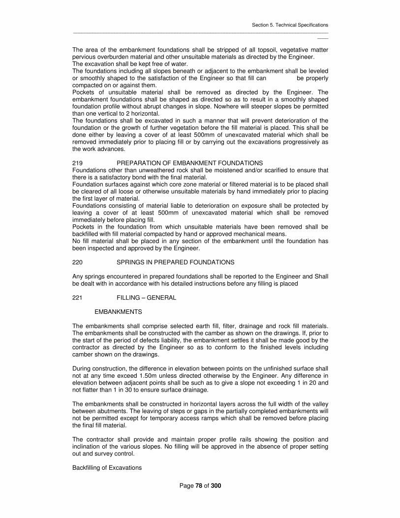
Section 5. Technical Specifications _____________________________________________________________________________________________
____
Page 78 of 300
The area of the embankment foundations shall be stripped of all topsoil, vegetative matter pervious overburden material and other unsuitable materials as directed by the Engineer. The excavation shall be kept free of water. The foundations including all slopes beneath or adjacent to the embankment shall be leveled or smoothly shaped to the satisfaction of the Engineer so that fill can be properly compacted on or against them. Pockets of unsuitable material shall be removed as directed by the Engineer. The embankment foundations shall be shaped as directed so as to result in a smoothly shaped foundation profile without abrupt changes in slope. Nowhere will steeper slopes be permitted than one vertical to 2 horizontal. The foundations shall be excavated in such a manner that will prevent deterioration of the foundation or the growth of further vegetation before the fill material is placed. This shall be done either by leaving a cover of at least 500mm of unexcavated material which shall be removed immediately prior to placing fill or by carrying out the excavations progressively as the work advances. 219 PREPARATION OF EMBANKMENT FOUNDATIONS Foundations other than unweathered rock shall be moistened and/or scarified to ensure that there is a satisfactory bond with the final material. Foundation surfaces against which core zone material or filtered material is to be placed shall be cleared of all loose or otherwise unsuitable materials by hand immediately prior to placing the first layer of material. Foundations consisting of material liable to deterioration on exposure shall be protected by leaving a cover of at least 500mm of unexcavated material which shall be removed immediately before placing fill. Pockets in the foundation from which unsuitable materials have been removed shall be backfilled with fill material compacted by hand or approved mechanical means. No fill material shall be placed in any section of the embankment until the foundation has been inspected and approved by the Engineer. 220 SPRINGS IN PREPARED FOUNDATIONS Any springs encountered in prepared foundations shall be reported to the Engineer and Shall be dealt with in accordance with his detailed instructions before any filling is placed 221 FILLING – GENERAL EMBANKMENTS The embankments shall comprise selected earth fill, filter, drainage and rock fill materials. The embankments shall be constructed with the camber as shown on the drawings. If, prior to the start of the period of defects liability, the embankment settles it shall be made good by the contractor as directed by the Engineer so as to conform to the finished levels including camber shown on the drawings. During construction, the difference in elevation between points on the unfinished surface shall not at any time exceed 1.50m unless directed otherwise by the Engineer. Any difference in elevation between adjacent points shall be such as to give a slope not exceeding 1 in 20 and not flatter than 1 in 30 to ensure surface drainage. The embankments shall be constructed in horizontal layers across the full width of the valley between abutments. The leaving of steps or gaps in the partially completed embankments will not be permitted except for temporary access ramps which shall be removed before placing the final fill material. The contractor shall provide and maintain proper profile rails showing the position and inclination of the various slopes. No filling will be approved in the absence of proper setting out and survey control. Backfilling of Excavations

Section 5. Technical Specifications _____________________________________________________________________________________________
____
Page 79 of 300
Backfilling of excavations and trenches shall be carried out using material which is Homogeneous with the adjacent ground or as otherwise instructed by the Engineer. The material shall be thoroughly compacted by mechanical means to the approval of the Engineer in layers not exceeding 150mm compacted thickness and by means this will not damage the works. Any subsidence due to consolidation or inadequate compaction shall be made up by the Contractor at his additional compacted material. IV) Water stop and Jointing Materials Waterstop and jointing materials shall be obtained from an approved manufacturer. All waterstop and jointing materials which are not required for immediate use shall be stored at all times in a cool damp place Waterstop shall be manufactured of rubber or PVC (polyvinylchloride) as stated in the Bill of Quantities and shall be the type and size shown on the drawings. Site joints shall be made strictly in accordance with manufacturer’s instructions and all intersections and junctions shall be obtained preferably from the approved manufacturer. Joint filter shall be manufactured of natural bonding cork or other approved material .Joint filter shall be cut and trimmed accurately to suit the joint profile and shall be maintained accurately in position by means of an approved adhesive Joint sealing compounds shall be approved rubber/bituminous compounds suitable for sealing joints in horizontal and vertical/sloping concrete surfaces as appropriate .Sealing compounds shall be applied strictly in accordance with the manufacturer’s instructions and shall completely fill the joint recess. Surface primers shall be from the same manufacturers as the sealers themselves. Waterstop shall be located and maintained accurately in position and details of the proposed method of fixing shall be submitted to the Engineer for approval. On no account shall the waterstop be secured by nails or any other means involving puncture of or damage to the waterstop material unless purpose made nailing flanges are incorporate din the design of the waterstop 222. TRIAL EMBARKMENT At an early stage ' in the construction of the Works the Contractor shall construct a trial embankment, for the Construction of the dam embankment, using the plant and materials he proposes to use for the permanent works. The trial embankment shall be constructed in a location to be agreed with, the Engineer. The trial embankment shall be so sited as to allow a clear run of at least 5Qn for the compaction equipment and shall contain not less than 2000 mn of compacted fill. The trial embankment shall include all the principal types of earth fill material to be used in the construction of the embankment. The Contractor shall use the same equipment and techniques to construct the trial embankment as that which he proposes to use to construct the main embankment. In collaboration with the Engineer the Contractor shall determine on the trial embankment the loading of the rollers and the number of roller passes required to achieve the specified degree of compaction. In demonstrating his working methods the extractor shall cover the following items: - setting out Layer thickness control spreading and grading of fill

Section 5. Technical Specifications _____________________________________________________________________________________________
____
Page 80 of 300
Compaction of fill scarifying of previous layer moisture reduction of fill material in the borrow area spreading of filter material Wetting of fill material in the borrow area Reworking of a failed layer Removal of a failed layer Method of working after rain. The fill placed in the trial embankment shall cover the full range of moisture contents permitted. Before commencing the trial embankment the Contractor shall submit in writing his proposals for carrying out the trials for the approval of the Engineer. On completion of tile trial embankment the Contractor shall submit a report on the trials to the Engineer. No earth fill shall be placed as part of the permanent works until the trial embankment relevant to that section of work has been completed. 223 SPECIAL TEST PROCEDURES FOR LABORATORY TESTING OF SOILS The Contractor's attention is drawn to the fart that widely varying results can be obtained in laboratory tests en tropically weathered soils due to minor differences in the testing procedure. Laboratory testing of "soils shall be carried out in accordance with British Standard Specification 1377 but with the following modifications. (i) Sample Preparation BS 1377 states that initial sample preparation should include air or oven drying. As this can affect the structure of the soil this shall not be done, but the soil shall be used from its natural state, wetting or drying as appropriate to achieve the required moisture content for the test. (ii) Atterberg Limit Determination For liquid limit determination the sample shall be mixed for 5 minutes after adding the distilled water. The type of testing machine used shall be stated on the results sheet. (iii) Compaction Test (Proctor) A fresh specimen for the bulk sample shall be used for the determination of each point on the curve. This will require about 50 Kg of material to ensure that adequate material is available for one specimen per point. Field moisture content may be wetter or drier than Proctor Optimum. If wetter, the sample shall be allowed to dry naturally in air to obtain points on the dry side of optimum. If the natural moisture content is drier than optimum the sample shall not be allowed to dry out but progressive amounts of water shall be added to each specimen to achieve the desired water content. The specimen shall be mixed for a fixed time, depending on the characteristics of the material. It is important that sufficient points are determined to show a well defined peak. In no case shall less than 5 points be used. 224 COMPACTION TEST FOR EARTHFILL The standard test: for determination of the density/moisture content relationship for earthfill shall be that described in British Standard Specification 1377 "Determination of the Density/Moisture Relation of Soil (Standard Laboratory Method)" using the 2.5 kg. Standard rammer modified as required by Clause 223. This test" is commonly referred to as the "Proctor Compaction Test".

Section 5. Technical Specifications _____________________________________________________________________________________________
____
Page 81 of 300
The "Proctor Optimum" moisture content shall be defined as “that moisture content which will result in a maximum dry unit weight of soil when subject to the Proctor Compaction Test". 225 FIELD DENSITY TEST FOR EARTHFILL The standard test for determination of the field density for earthfill shall be that described in British Standard Specification 1377 "Determination of the dry density of soil on the site" Tests 15(A) or 15(B). This test is commonly referred to as the "Sand Replacement Test". The sand material used in this test shall be material passing the 0.6mm and retained on the 0.3mm B.S. test sieve as described in the above reference. Other methods of measurement of field density may be used for routine tests subject to the agreement of the Engineer. In addition one point Proctor tests shall be carried cut by taking the fill material at the field moisture content and applying Proctor compactive effort. The "Laboratory Proctor Dry Density" shall be defined as the dry density determined in this way. 226 BORROW AREAS Unless otherwise directed by the Engineer, suitable earthfill material for the embankment shall be obtained from the designated borrow areas identified and approved by the Engineer prior to the commencement of the works, and from the excavations. The Contractor shall construct and maintain al1 necessary access roads and bridges to the borrow areas. To facilitate efficient planning of his method of working, the Contractor shall at his own expense carry out trial holes and boreholes in the borrow areas to determine the quantity, condition and type of materials that will be encountered during excavation. The contractor shall submit to the Engineer his proposed method of working the borrow areas and shall not start site clearance or excavation at any borrow areas until he has obtained the Engineer’s permission and approval of his method of working in writing. The contractor shall work the borrow areas in a systematic manner and shall so arrange his method of working to minimize deterioration of the materials in the borrow areas both before and during excavation. The contractor shall provide all necessary drainage and pumping to ensure that the borrow areas are at all times free of standing water. Different types of materials from the borrow areas shall be kept separate for use in the works, and materials which is unsuitable for use in the works shall be disposed of to spoil tips solely designated for this purpose. The contractor shall spray access roads to borrow areas with water to minimize dust when this is considered necessary by the Engineer 227 CONSTRUCTION EQUIPMENT The Contractor shall provide the Engineer with details of all equipment which he proposes to use on the embankment. The Contractor shall not change such equipment without prior notice to the Engineer. Earthfill shall be compacted by means of heavy tamping rollers except in confined spaces. The type and weight of each roller used shall be such as will efficiently achieve the specified degree of compaction of a layer of earthfill not exceeding 200mm compacted thickness. In confined spaces where it is impracticable to use heavy rollers special means of compaction shall be employed. The fill in such spaces shall be compacted to a dry density not less than that of the adjacent areas of rolled fill.

Section 5. Technical Specifications _____________________________________________________________________________________________
____
Page 82 of 300
The Contractor shall submit to the Engineer details of the rollers which he proposes to use before bringing any roller onto the Site. All types of rollers brought en to the Site shall be tested on the trial embankments and no roller shall be used on the Permanent Works unless its suitability has been so demonstrated. Any roller which proves to be unsatisfactory shall not be used and any replacement shall likewise be tested on the trial embankments. Al1 tractors used for towing rollers shall be adequately powered so as to work satisfactorily as a combination when the rollers are fully loaded. 228 EARTHFTLL MTERIALS The various materials for use in the embankments shall comply with the following specifications:- Core Zone Material (Zcne 1) Earth fill for the core zone shall consist of approved plastic material of low permeability from the borrow areas or excavations. The material shall conform with the grading limits shown on the Drawings to be prepared by the Contractor and Approved by the Engineer, but may contain occasional stones of maximum dimension up to l00mm provided they are in small quantities and well distributed so as not to destroy the essentially impervious nature of the fill material. The material shall, if necessary, be treated to achieve the specified moisture contents. The treatment shall include but not by way of limitation such operations as sorting and rejecting unsuitable materials drying or spraying with water. Moisture content of the Zone 1 material shall be in the range CM3 +7% to CM3 +10% at the time of compaction. Shoulder Zone Material (Zcne 2) Material for the shoulder shal1 be generally as described for the core zone except that the material may contain coarse or permeable non-plastic material not suitable for the core zone, as indicated in the grading limits shown on the Drawings. Coarse and more permeable material shall be placed in the outer layers of the shoulder zones. Moisture content of Zone 2 material shall be in the range CMC to CMC + 5% at the time of compaction. 229 DRYING OF EAKTHFTLL MATERIALS The Contractor shall note that the natural moisture content of the material in the borrow areas is anticipated to be significantly in excess of the above moisture content range and that a substantial amount of drying will therefore be required. At the time of constructing the trial embankment the Contractor shall carry out drying trials on earthfill material in the borrow areas. The trials shall be used to determine the plant and methods to be used to enable the drying to be carried out efficiently and the drying rate that will be achieved. Before commencing the trials the Contractor shall submit in writing his proposals for the approval of the Engineer. On completion of the trials the Contractor shall submit a report en the trials to "the Engineer. During the rainy season significant drying of the earthfill may not be possible. During this period, with the prior written approval of the Engineer, the Contractor may place earthfill in the shoulder zones at moisture contents up to CM3 + 15% with the inclusion of sand drains. Sand drains shall be 0. 5m square placed at a maximum spacing of 2.5 metres both horizontally

Section 5. Technical Specifications _____________________________________________________________________________________________
____
Page 83 of 300
and vertically and consist of Zone 3 filter material. Details of the proposed sand drain layout and discharge arrangements shall be submitted by the Contractor to the Engineer for approval. The Contractor shall note that earthfill material at a moisture content of OC + 15% is likely to have low shear strength and may not support the weight of normal earth moving equipment. 230 PLACING OF EARTHFILL Unless otherwise indicated on the Drawings earthfill shall be placed and compacted in continuous layers which are approximately horizontal and not more than 20Cmn compacted thickness. Before placing any layer, the surface of the underlying layer shall be moistened and/or worked with a scarifies or other suitable equipment if in the opinion of the Engineer such moistening or working is necessary to ensure that there is a satisfactory bond between the two layers. Furthermore, before placing a new layer, any material in underlying layers shall be removed or re-worked to the satisfaction of the Engineer if in his opinion:- (i) It has been compacted outside the limits of moisture content specified herein, or (ii) It has received less compaction than specified herein, or (iii) It has been cracked by drying, softened by wetting, or damaged by any other cause. At the time of compaction in the embankment, each portion of the fill shall have a moisture content within the specified moisture content range above " Proctor Optimum moisture Content", or within such other range related to the Proctor Optimum as the Engineer may determine after the construction of the trial embankments. If it is necessary to add water, this shall be done well in advance of placing by spraying at the borrow pits. Supplementary water may be added on the embankment, but only from tankers producing a uniform spray controlled from the cab. If it is necessary to dry the material all necessary work such as ripping, aeration with rotary cultivators, harrowing, etc. shall be carried out before transporting the material to the embankment. The Contractor shall be responsible for ensuring that the moisture content of each portion of fill is uniform and within the specified limits at the time of compaction and shall use such plant as may be necessary to achieve this. Any material which has been placed in the embankment and prepared for compaction at moisture content outside the limits specified and any material being compacted, which has been damaged by drying or wetting or any other cause, shall be removed or re-worked to the satisfaction, of the Engineer. Holes formed in the embankment by the removal of samples for tests shall be filled and consolidated in homogeneity with the surrounding fill. The routes taken on the embankment by vehicles and mechanical plant shall be varied to avoid tracking and local over compaction. 231 EARTHFILL SAMPLING The Contractor shall take samples from the embankment as directed by the Engineer's Representative to enable the following tests to be carried out: (i) Field dry density and moisture content (ii) One point Proctor compaction (iii) Proctor compaction (iv) Undrained shear strength on l00mm diameter undisturbed samples of earth fill The normal rate of sampling shall be determined by the Engineer.

Section 5. Technical Specifications _____________________________________________________________________________________________
____
Page 84 of 300
The frequency of sampling shall be determined from the results of previous tests, the quality of the material revealed during such tests and the uniformity of such quality. The frequency may be amended as required by the Engineer. In the event that individual compaction tests en samples of earthfill material " result in widely ranging values for Proctor Optimum moisture content and Proctor Optimum dry density, the Engineer may require that during the construction of the trial embankment and from time to time during the construction of the main embankment, laboratory Proctor compaction tests shall be carried out at the same frequency as field density tests en material taken from the fill adjacent to the location of the field density test. Should the fill placed, in the opinion of the Engineer, be thought likely not to comply with the Specification, the Contractor shall, if directed by the Engineer, carry out additional tests. 232 EARTHFILL – COMPACTION CONTROL Earth fill shall be compacted in such a manner that the average percentage compaction of the fill at any time shall be not less than 100%, where percentage compaction is defined as the ratio of Field Dry Density: Laboratory Proctor Dry Density. Results of field dry density tests shall be examined in consecutive batches of 25 results, which shall conform to the following requirements:- (i) The average of the ratio of the Field Dry Density: Laboratory Proctor Dry Density for each sample shall be rot less than 100%. (ii) Not more than 5% of the results of each batch shall show a compaction of less than 95% Laboratory Proctor Dry Density. (iii) The standard deviation of the results of each batch shall be not greater than 3%. Separate compaction records shall be kept for the core zone and shoulder zone and also for materials of differing properties within those zones. Material which has been, compacted to a dry density less than that required by this Specification or at moisture content outside the agreed range shall be removed or re-worked and recompated until the required properties are achieved. In this case the field dry densities recorded before removal or recornpaction of the material shall be emitted from the deviation. 233 EARTHFILL TOLERANCES The tolerances of finished earthfill with respect to the dimensions and lines shown on the drawings shall be as follows: embankment slopes + 200, - 0 berm level + 100, - 0 crest road +50, - 0 filter thickness + 100 - 0 234 FILTER AND ERAINAGE MATERIALS Filter and drainage materials shall comply with the following requirements:- 1 Filter Material (Zone 3) Filter material shall consist of hard durable crushed rock or clean natural quartz sand derived from sources approved by the Engineer. Filter materials after compaction shall be evenly graded between the limits shown on the Drawings. Not more than 5% shall pass the no, 200 size sieve (0.07 mm).

Section 5. Technical Specifications _____________________________________________________________________________________________
____
Page 85 of 300
Filter material which has become mixed or contaminated with earthfill material shall not be used. 2. Drainage Material (Zone 4) Drainage material shall consist of hard durable clean natural gravel or crushed rock derived from quarries or other sources approved by the Engineer. Drainage materials shall not crush or break down during compaction and after compaction shall be evenly graded between the limits shown on the Drawings. The materials shall meet the following test: requirements: 1. Material passing the no. 200 sieve size shall be non-plastic. 2. Los Angeles abration test - loss not to exceed 3O% by mass. 3. Sodium Sulphate soundness test - loss not; to exceed 4. Water absorption test - not to exceed 2%. 235 FILTER AND DRAINAGE MATERIAL - PLACING AND COMPACTION Filter material shall be placed in the filter chimney in approximately horizontal layers not exceeding 20Qnm compacted thickness. Filter and drainage materials shall be placed in the drainage blanket in 200 and 25Qrm layers respectively. Each layer shall be compacted by means of a vibrating compaction machine to achieve a specified relative density. ‘The relative density will be determined by the Engineer after laboratory trials en site but will rot exceed 70% of relative density (as determined by the United States Bureau of Reclamation relative density test Designation E-12). The filter chimney shall be placed by means of a spreader, details of which shall be submitted to the Engineer for approval. Horizontal filters shall be thoroughly wetted during compaction. Care shall be taken that earthfill material does not become mixed with filter or drainage materials and that the earthfill is not softened by water used in connecting filter material. Filter or drainage materials which become contaminated by mixing with adjacent zones shall be replaced. 236 UPSTREAM SLOPE PROTECTION - MATERIALS The slope protection zone en the upstream face of the dam embankment shall consist of hand placed masonry on a gravel transition bed. Under-lying the gravel transition bed will be a sand transition filter layer. The materials shall comply with the following requirements. 1 Sand Transition (Zone 3a) The sand transition filter layer shall comply generally with the requirements for the Zone 3 filter material (See Clause 233). 2. Gravel Transition (Zone 4a) The gravel transition layer shall comply generally with the requirements for Zone 4 gravel transition material (see Clause 233). 3 Hand-Placed Masonry Hand placed masonry shall be obtained from the proposed quarry site or other approved source and shall be hard and durable. Individual rocks shall be sound and generally free from cracks, seams and other defenses that would decrease their resistance to water action.

Section 5. Technical Specifications _____________________________________________________________________________________________
____
Page 86 of 300
The stones forming the face of the surface shall have an average weight of not less than 15 kilogram and shall be roughly squared and dressed. The Contractor may propose the use of dumped Rip-Rap as an alternative form of upstream slope protection. The size of rocks required are not anticipated to be available from the designated quarry sites and an alternative source providing hard, durable rock should be proposed. The grading and layer thickness requirements for the rip-rap shall be determined by the Engineer: The rip-rap shall be evenly graded and of maximum size equal to the thickness of the layer. Not more than 10% of the rip-rap shall be smaller than 150mm size. Individual rocks shall be sound and generally free from cracks, seams and other defects that would decrease their resistance to water action. 237 UPSTREAM SLOPE PROTECTION 237.1 Sand and Gravel Transition Layers The sand and gravel transition material shall be placed in layers in such a manner as will prevent segregation. Ire layers need not be compacted in place but shall be placed in such a manner as will result in uniform layers of the required thickness as shown on the Drawings. 237.2 Hand Placed Masonry The thickness of the stones forming two-thirds of the surface area shall be not less than the full thickness of the layer and the dimensions of any stone forming the face of the layer shall not be less than two-thirds of the thickness of the layer. The thickness of the stones shall be measured normal to the face of the surface. The stones shall be laid with close joints and the spaces between the stones filled with small stones and gravel or crushed rock. 237.3 Dumped Rip-Rap The rip-rap shall be placed in such a way that the larger pieces of rock are uniformly distributed throughout the layer. The smaller rock fragments shall fill the gaps between the larger pieces so as to produce a dense and uniform layer of the required thickness. The rip-rap shall not be compacted in place. The method of placing shall be such as does rot damage the underlying gravel bed and sand transition layer. The rip-rap shall finally be worked by hand to achieve the design slopes and thickness. 238 WAVE WALL The wave wall shall be constructed using the same size and source of stones used for the hand placed masonry protection. It shall be constructed in accordance with the requirements of Clause 806. 239 MEASURING INSTRUMENTS The following measuring instruments are to be supplied under a Nominated Sub-Contract, for installation in the foundation and embankments. 1. Vibrating wire piezometers 2. Observation wells 3. Total pressure cells 4. Inclinometer tubes 5. Surface settlement markers
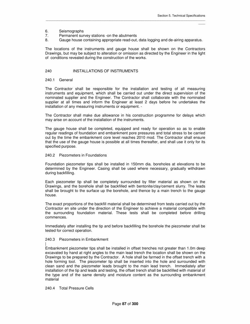
Section 5. Technical Specifications _____________________________________________________________________________________________
____
Page 87 of 300
6. Seismographs 7. Permanent survey stations -on the abutments 8. Gauge house containing appropriate read-out, data logging and de-airing apparatus. The locations of the instruments and gauge house shall be shown on the Contractors Drawings, but may be subject to alteration or omission as directed by the Engineer in the light of conditions revealed during the construction of the works. 240 INSTALLATIONS OF INSTRUMENTS 240.1 General The Contractor shall be responsible for the installation and testing of all measuring instruments and equipment, which shall be carried out under the direct supervision of the nominated supplier and the Engineer. The Contractor shall collaborate with the nominated supplier at all times and inform the Engineer at least 2 days before he undertakes the installation of any measuring instruments or equipment. - The Contractor shall make due allowance in his construction programme for delays which may arise on account of the installation of the instruments. The gauge house shall be completed, equipped and ready for operation so as to enable regular readings of foundation and embankment pore pressures and total stress to be carried out by the time the embankment core level reaches 2010 mod. The Contractor shall ensure that the use of the gauge house is possible at all times thereafter, and shall use it only for its specified purpose. 240.2 Piezometers in Foundations Foundation piezometer tips shall be installed in 150mm dia. boreholes at elevations to be determined by the Engineer. Casing shall be used where necessary, gradually withdrawn during backfilling. Each piezometer tip shall be completely surrounded by filter material as shown on the Drawings, and the borehole shall be backfilled with bentonite/clay/cement slurry. The leads shall be brought to the surface up the borehole, and thence by a main trench to the gauge house. The exact proportions of the backfill material shall be determined from tests carried out by the Contractor en site under the direction of the Engineer to achieve a material compatible with the surrounding foundation material. These tests shall be completed before drilling commences. Immediately after installing the tip and before backfilling the borehole the piezometer shall be tested for correct operation. 240.3 Piezometers in Embankment | Embankment piezometer tips shall be installed in offset trenches not greater than 1.0m deep excavated by hand at right angles to the main lead trench the location shall be shown on the Drawings to be prepared by the Contractor. A hole shall be farmed in the offset trench with a hole forming tool. The piezometer tip shall be inserted into the hole and surrounded with clean sand and the piezometer leads brought to the main lead trench. Immediately after installation of the tip and leads and testing, the offset trench shall be backfilled with material of the type and of the same density and moisture content as the surrounding embankment material 240.4 Total Pressure Cells

Section 5. Technical Specifications _____________________________________________________________________________________________
____
Page 88 of 300
Total pressure cells shall be installed in clusters of five cells at the spacing and orientation shown on the Drawings. The cells shall be placed against fiat clay faces cut to the required orientation and carefully backfilled and compacted by hand. The level and exact orientation of each cell shall be recorded. 240.5 Inclinometers The inclinometers comprise specially shaped aluminum tubes, in 3.0m lengths, with 0.3m. Long couplings. Horizontal movements are measured by means of a torpedo probe which slides inside the tube. Ring magnets are placed at intervals along the tube to measure axial displacements. The key ways shall be orientated such that movements are measured parallel to and at right angles to the dam axis. The tubing shall be installed in the foundations in a I50mm diameter borehole, anchored at its base by a concrete plug. The borehole shall be backfilled with bentonite/clay /cement slurry of proportions determined by the tests carried out under Clause 240.2. The completed inclinometer tube shall extend above the finished embankment level, and a concrete slab placed around the top of the tube as shown on the Drawings. Heavy compaction equipment shall not be permitted to approach within 1.5m of the inclinometer tubes. Two layers of fill, of approximately 3m dia. shall be placed around tubes in advance of general filling and compacted by hand rammer. Bulk earthfilling will not be approved unless the local filling around the inclinometer tubes has been completed. The Contractor shall take all care necessary to avoid damage to inclinometer tubes. Any damage to tubes within the fill shall be made good by excavation locally and jointing new sections. The Contractor shall be responsible for checking tubes by insertion of a dummy probe and reporting any damage. Any damage below 1 meter of fill will require the instrument to be completely re-drilled and re-installed. All remedial work necessary due to damage by the Contractor or his negligence shall be as directed by the Engineer’s Representative and all at the Contractors expense. 240.6 Observation Well Observation wells shall be installed in 150mm diameter boreholes as shown on the Drawings. The depth of the borehole will be determined by the Engineer. The use of drilling mud or lubricants will not be permitted. The observation well comprises 50mm diameter uPVC tubing with a perforated section one meter in length. The perforated section shall be completely surrounded with clean sand filter material as shown on the Drawings. The borehole shall be backfilled with bentonite/clay /cement slurry of the same mix proportion determined under Clause 240.2. The Contractor shall be responsible for protection of the installation against damage by plant and for maintaining the tube free of debris. In the event of damage or blockage the Contractor shall at his own expense as directed by the Engineer either make good the damage or install a replacement observation well. 240.7 Seismograph

Section 5. Technical Specifications _____________________________________________________________________________________________
____
Page 89 of 300
The seismograph shall be installed in a concrete chamber to be shown on the Drawings. 241 LEADS FROM PIEZOMETERS AND TOTAL PRESSURE CELLS Leads shall be laid in continuous lengths from the top of the boreholes to the gauge houses. No joints shall be permitted in the leads in the trenches. The joints between the tips/cells and leads or between leads shall be wrapped with approved corrosion resisting tape. Each tip/cell shall be connected to the appropriate terminal panel in the gauge house. To compensate for differential settlement along the length of lead, a slack of 5m per 100m shall be distributed evenly along the lead. Each lead shall be marked at the ends and every 20m with approved adhesive plastic bands stamped with the appropriate piezometer tip reference number in a way that does not damage the leads. Leads from the piezometer tips shall be laid in trenches 0,6m wide and not greater than 1 meter deep. Trenches may be excavated mechanically to within 1. 5m of any installed lead but shall be trimmed by hand to the required lines and levels. All stones and sharp objects shall be removed from the bottom of the trenches. The leads in trenches shall be laid in layers. The leads in each layer shall be separated from each other by at least 20mm horizontally. Each layer of leads shall rest on and be covered by a layer of the appropriate fill material compacted to the same density and moisture content as the surrounding material. The layer of fill material shall be free of stones and other objects which are liable to damage the leads. The trenches shall be backfilled with selected core material placed in l00mm thick layers and compacted by hand rammer to the same density and moisture content as the surrounding material. Where instrument lead trenches cross the core trench shall be backfilled at intervals with 500 wide bentonite clay (5% bentonite by volume) cut-offs. These cut-offs shall be at 5m intervals where trenches run across the core and at 15m intervals where trenches run along the core. Immediately after backfilling the trenches the Contractor shall test the installation. If the installation is found to be faulty the leads and/or tips/cells shall be repaired or replaced. The Contractor shall carry out the installation of tips/cells and leads with the utmost care and shall ensure that the leads are protected from ingress of soil, prolonged exposure to direct sunlight, or from other damage. Heavy compaction equipment shall not be permitted to cross the leads if the soil cover is less than 0.9m.Open trenches shall be covered with tarpaulin or similar at all times to avoid damage by rain. Leads shall be protected by a steel conduit between the downstream toe of the dam and the gauge house. 242 SURFACE SURVEY MONUMENTS The Contractor shall be responsible for establishing lines of survey monuments in locations selected by the Engineer 'in longitudinal and lateral directions along and across the dam embankment crest and slopes, and permanent survey base stations en undisturbed ground clear of the embankment. The permanent survey stations shall be located on stable ground. The monuments shall comprise steel rods of 20mn diameter set in concrete as shown on the Drawings. Installation of the survey monuments shall take plane as soon as possible after completion of that section of the work. The monuments and survey stations shall be clearly marked and protected from damage.

Section 5. Technical Specifications _____________________________________________________________________________________________
____
Page 90 of 300
The Contractor shall provide facilities for the Engineer to carry out routine measurements to determine the level of each monument, the linear distance between monuments and their deflection from the lines between base stations. 243 STONE PITCHING Stone pitching shall be hand-placed and bedded on a 5Omm thick layer of Grade 15 concrete. The stones shall be roughly rectangular in shape of minimum dimension 15Omm and rough hammer dressed on the face and sides. The stones shall be join-ted in 1:3 cement/sand mortars. The stones shall break joint in every direction and the interstices shall be packed with stone chippings. Where the thickness of pitching is such that two or more layers of stones are required the layers shall be keyed together by means of stones projecting through from the lower to the upper course and such stones shall be provided at the rate of two for every one square meter. 244 GABION PROTECTION Gabions shall be of the hexagonal wire mesh type, with mesh dimensions of 80mm x 100mm.The minimum dimension shall not exceed 83nm. Wire shall be galvanized prior to weaving the mesh to resist corrosion from river water. All wire used in the fabrication of the gabion and in the wiring operation during construction shall be in accordance with BS 1052 Mild Steel wire having a tensile strength of 38-50 kg/mm2. The sizes of the wires shall be in accordance with the table below. All wire shall be galvanized to BS 443 All wire used in the fabrication of gabions and in the wiring operations during construction shall, after galvanizing, have extruded onto it a coating of polyvinyl chloride compound referred to as PVC. The coating shall be black in color, not less than 0.4mn thickness and shall be capable of resisting deleterious effects of exposure. The gabions shall be of the following standard sizes: 2m x 1m x 0.5m 2m x 1m x 1m 6m x 2m x 0.3m The gabions shall be provided with diaphragms to divide the boxes in compartments with a maximum dimension in any direction of 1m. Joints shall be flexible and shall consist of not less than one and a half full turns of wire, at each mesh point of the joint line. Rcckfill for gabions shall consist of hard durable clean rock derived from a quarry approved by the Engineer. The maximum size shall be 22Om and the minimum size 12Omm. Up to 10% of sore smaller blinding material (minimum 75mm) to fill the internal voids at the top will be allowed. The gabions shall be placed in their final positions overlying a synthetic filter membrane prior to filling with rock and shall then be tied together and filled with rock. After filling with rock the tops shall be closed and securely tied. The larger rocks shall be placed on tie upper face of the gabion in order to present a reasonably closed surface. All assembly, erection, stretching, filling with rock and final filling shall be in accordance with the instructions as issued by the manufacturer. The synthetic filter membrane shall be a non-woven fabric, Terram 1000

Section 5. Technical Specifications _____________________________________________________________________________________________
____
Page 91 of 300
245 FORMING BANKS AND FILLED AREAS This clause shall apply to banks and areas other than in the dam embankment. Banks and filled areas shall be farmed to levels, dimensions and shapes shown on the Drawing or as directed by the Engineer. The sites of banks and filled areas shall first be stripped of all grass and topsoil, and all roots, vegetative matter and other unsuitable materials removed. Earthfill material shall consist of approved material from borrow areas or surplus from excavations at a moisture content in the range 0 to +5% relative to Proctor optimum moisture content. The fill shall be placed in layers of not more than 15Onm compacted thickness, each layer being compacted by means of six passes of a roller approved by the Engineer. 246 TOPSOILING AND GRASSING Embankment slopes and other areas to be grassed shall be covered with a consolidated layer of organic topsoil in accordance with Clauses 205 and 206 not less than 150mm thick. The surface shall be well raked, brought to a fine tilth and reverted with interlaced split bamboo or such other methods as are necessary to prevent erosion. Grassing shall be established by the planting of runners unless otherwise directed by the Engineer. Where directed by the Engineer, grass trials shall be undertaken to determine the optimum mixture of fertilizers and herbicides for the effective establishment of grass areas. Surfaces required to be grassed shall be planted with "Kikuyu" type runners or other approved local grass obtained from an approved local source and shall be planted at approximately 150mm x 150mm spacing so as to form a dense protective mat. Soiling and grassing of slopes shall be carried out immediately a slope has been formed and shall be watered as necessary 'to ensure quick development of grass coverage. Grass shall be replanted if the first or subsequent plantings are unfruitful or if for any reason the grass is destroyed. Any damage caused by rain or other reason shall be made good immediately. Grass shall be kept free of weeds and shall be cut, watered, fertilized and weeded as necessary, The Contractor shall supply all labour and attendance for this purpose until the end of the Period of Defects Liability. By the time of the final construct Ion inspect ion al 1 areas to be grassed shall be substantially covered with healthy, well established, firmly rooted grass and the area shall be free from erosion rills and channels. 247 RESTORATION OF BORROW AREAS SPOIL TIPS AND QUARRIES Borrow areas, spoil tips and quarries shall be graded to a neat appearance and shall be finished to safe and fair slopes to ensure stability and drainage. Contour drains shall be excavated to minimize surface erosion as directed by the Engineer. Where directed by the Engineer areas shall be resoiled with at least 100mm of topsoil and grassed. 248 CONSTRUCTION PORE PRESSURES Pore pressures in the dam embankments and foundations will be monitored from an early stage in the construction of the embankments. If in the opinion of the Engineer excessive pore pressures are developing the Engineer will instruct the Contractor temporarily to suspend the filling operations.

Section 5. Technical Specifications _____________________________________________________________________________________________
____
Page 92 of 300
249 ROADS 249.1 General The Contractor shall construct and maintain the permanent roads, comprising the embankment crest road and access roads, as shown on the Drawings 249.2 Embankment Crest Road The embankment crest road shall be constructed as follows: Sub-base The sub-base (foundation) for road shall comprise hard graded approved stone rolled to a compacted thickness of 225mrn as shown on the Drawings, with an 8 tonne roller. The sub-base material shall conform to the following grading: 100% by weight passing 4Omm sieve 75%-85% by weight passing 20mm sieve 40%-50% by weight passing 6mm sieve Road base The roadbase shall comprise reasonably graded gravel or crushed stone maximum size 20mm of thickness 150mm as shown on the Drawings, well rolled to result in a smooth even surface true to camber line and level. Before carrying out final surfacing the Contractor shall make good all irregularities in the road base caused by his site traffic during the construction of the Works and shall restore the surface to camber as necessary and brush it clean. Surface Dressing The surface dressing shall be applied as follows: a prime coat of MC 30 approved cold applied bituminous emulsion applied with an approved sprayer at the rate of approximately 0.8 to 1.2 1/m2 depending on site trials. a first seal coat comprising an approved hot applied cutback bitumen (MC 3000) applied with an approved sprayer at the rate of approximately 1.5 1/m2 and evenly blinded with l0-14mm graded hard stone chippings at the rate of 80 m2/m3 rolled with an 8 tonne roller. a second seal coat similarly applied with mc 3000 hot applied cut back bitumen and evenly blinded immediately with 3 to 6mn graded hard stone chippings. 249.3 Access Roads Access roads shall be constructed as follows: (i} Sub-Base The sub base material for access roads shall comprise 150mm thick graded approved stone rolled to the compacted thickness with an 8 tonne roller. The sub base material shall conform to the following gradings: 100% by weight passing 40mm sieve 75-85% by weight passing 20mm sieve

Section 5. Technical Specifications _____________________________________________________________________________________________
____
Page 93 of 300
40-5O% by weight passing 6mm sieve Gravel Wearing Course The wearing course for access roads shall comprise a 20Gmm average thickness of approved grovel rolled to a smooth even surface, true to crossfalls, line and level. The term "gravel" used shall be any such material which might be specified for use as a wearing course, e.g. murrain, sore forms of partly decomposed rock and coral, soft rocks, spalls, clayey sand and crushed rock. A "gravel wearing course" will be a top surfacing course made from ore or from a combination of these materials and will be applied to sores of the road formations where no pavement and final bituminous surface is included in the Contract. Where permanent access roads are used by the Contractor for access during construction the Contractor shall reinstate to the satisfaction of the Engineer wearing courses to the thickness grade and crossfall as shown on the Drawings. Laying and Compacting Gravel Wearing Course. Gravel wearing course material shall be spread in a uniform layer across the full width required, pulverized so that the maximum size of any particle is not greater than one half the compacted thickness of the layer. It shall then be mixed, watered if directed by the Engineer, graded and compacted by at least 6 complete passes of a 10 tonne smooth wheeled roller or other equivalent and graded to final level. The" compacted thickness of any layer shall not exceed 150mm and where a greater compacted thickness is required the material shall be laid and processed in two or more layers. The average thickness of the wearing course measured at seven points over a length of 100mm shall be at least equal to the thickness specified or ordered. The final average width of the wearing course, measured at seven points over a length of 100m shall be at least equal to the width specified or ordered and at no point shall the distance between the edge of the wearing course and the centerline of the road be less than specified or ordered by more than 100mm. Footpaths Footpaths shall be constructed with a 150mm average compacted thickness of gravel wearing course as specified in Section 249.3. Kerbs and Edgings Where indicated on the drawings kerbs shall be laid on the embankment crest rood or access roods in accordance with the details shown. Precast concrete kerbs, edgings and quadrants shall be used, and shall be hydraulically pressed and shall comply with the requirements of BS 340. Kerbs shall be bedded on a layer of mortar not less 10 mm thick on a concrete footing and hunched with Grade 15 concrete. Where the radius of lire kerb line is less than 15m kerbs of the appropriate radius shall be used. Kerbs drainage and galleys shall be installed where shown on the drawings. Galleys shall be of precast concrete with gratings and frames shall be of the untrapped type. Galleys shall be

Section 5. Technical Specifications _____________________________________________________________________________________________
____
Page 94 of 300
reinforced and comply with the requirements of BS 556. Gratings and frames shall comply with the requirements of BS 497. All galleys shall be laid on and surrounded with at least 200mm of Grade 15 concrete, brought up to the underside of the frame. Opening to any pipe or gulley laid but not yet connected shall be covered with temporary stoppers or covers.

Section 5. Technical Specifications _____________________________________________________________________________________________
____
Page 95 of 300
SECTION 3 CONCRETE INDEX 301 GENERAL
302 CONCRETE
302.1 Requirements
302 . 2 Strength
302.3 Mixes
302 . 4 Quality Control
302.5 Production
302.6 Cement
302.7 Aggregates
302.8 Waiter
302.9 Admixtures
302.10 Control Of Alkali-Silica Reaction
303 REINFORCEMENT
303.1 Steel
303.2 Storage
303-3 Bending And Fixing
303.4 Couplers
304 Formwork
304.1 Requirements
304.2 Sawn Formwork
304.3 Wrought Formwork
304.4 Special Wrought Formwork
304.5 Tolerances
304.6 Striking And Removal
305 CONCRETING
305.1 Requirements
305.2 Transporting
305.3 Placing And Compaction
305.4 Concreting In Deep Lifts
305.5 Cold Weather – Concreting
305.6 Hot Weather Concreting
305.7 Hot Weather Concreting
305.8 Holes, Cavities And Fixings
305.9 Protection And Curing

Section 5. Technical Specifications _____________________________________________________________________________________________
____
Page 96 of 300
305.10 Joints
305.11 Finishes - General
305.12 Surface Finishes
305.13 Making Good
305.14 Removal And Replacement O£ Unsatisfactory Concrete
306 TESTING
306. 1 Sampling And Testing
306.2 Loading Tests
307 SPECIAL CONCRETE
307.1 No-Fines Concrete
307.2 Air-Entrained Concrete
307.3 Concrete In Benching
307.4 Ready Mined Concrete
307.5 Granolithic Concrete
307.6 Pneumatically Applied Mortar
307.7 Pumped Concrete
308 PRECAST CONCRETE
308.1 Requirements
300.2 Weir Blocks and Sills
308.3 Coping Blocks and Weir Blade Holders
308.4 Kerbs
300.5 Paving Slate
308.6 Other Blocks
300.7 Wall Units
300.8 Other Items
309 SITE BOOKS AND STANDARDS
309.1 Instruction to be Recorded
309.2 Site Diary
309.3 Copies of Standards and Codes
310 WATER RETAINING STRUCTURES - SPECIAL CLAUSES
310.1 Making Good
310.2 Construction Joints in Water Retaining Structures
310.3 Water Tightness of Structures
311 TESTING OF WATEK-RTF PAINING STRUCTURE
312 CLEANSING AND STOU.LIZING WATER-RWAINING STRUCTURES

Section 5. Technical Specifications _____________________________________________________________________________________________
____
Page 97 of 300
SECTION 3 CONCRETE 301 GENERAL The standard of materials and of workmanship shall not be inferior to the recommendations of the current: (a) British Standard Code of Practice BS 8110. The Structural Use of Concrete or British Standard Code of Practice BS 8007- Design of concrete structures for Retaining Aqueous liquids and (c) Appropriate British Standards or (d) Approved Kenya Bureau of Standards or Ministry of Works Standards, if any or (f) Other equivalent and approved international standards. (Which is applicable to the particular structures) The requirements outlined in the above documents must be read with those of this Section of the Specification and where any conflict exists between the recommendations of the above and of this Specification, the requirements of this Specification shall prevail. As and when required by the Engineer the contractor shall prepare and submit, before commencing the work, a time-chart (additional to the general programme) detailing the various operations for concrete work. No material shall be used in the Works until prior approval for its use has been given by the Engineer; neither shall any change in the nature, quality, kind, type, source of supply or manufacture be made without the Engineer’s permission. Names of manufacturers and test certificates for materials not supplied by the Employer shall be supplied as soon as possible to the Engineer. The cost of providing samples and the cost of carrying out tests required by 306.1 (except as otherwise provided in the Conditions of Contract) together with the cost of supplying equipment for sampling and site testing indicated in columns 3 and 4 of Table 3.6 of this Section of the Specification shall be borne by the Contractor (see also Clause 306.1). During the progress of the works, consignment notes for materials not supplied by the Employer shall be supplied to the Engineer giving details of each consignment. The use of the word "approved" in this Specification refers to the approval of the Engineer. Cross references between certain Clauses of this Specification have been shown in brackets following the particular item. 302 CONCRETE Requirements The mix proportions shall be selected to ensure that the workability of the fresh concrete is suitable for the conditions of handling and placing, having regard to the structural element being constructed, the disposition of reinforcement, and taking full account of the environment to which it will be subjected. The minimum cement contents and maximum water/cement ratios of designed mixes shall be as given in Table 3.1. In the event of sulphate exposure precautions requiring lower cement content than those required for normal conditions the latter requirement shall prevail. The maximum cement content in any mix shall not exceed 500 kg/m for normal structures and 425 kg/m3' for liquid retaining structures

Section 5. Technical Specifications _____________________________________________________________________________________________
____
Page 98 of 300
In all cases of mix proportioning, the added water shall be included with due allowance for the moisture contained in the aggregates and shall be the minimum consistent with the workability requirements. Batch mixing machines shall comply with the requirements of BS 1305. They shall be provided in such numbers and of such capacity as to ensure a continuous supply of freshly mixed concrete at all times during construction. Continuous mixing machines shall be used only with the written permission of the Engineer. Cement Cement shall comply with one of the following sub-Clauses (i) to (vi) below:- BS 12(Ordinary and rapid hardening Portland BS 146 (Portland-blast furnace cement). BS 4027 (Soleplate-resisting Portland cement). BS 6588 (Portland pulverized-fuel ash cement) provided that sub-Clause (vii) below is complied with. A mixture of BS 12 (Portland cement) and BS 3892: Part 1 (Pulverized-fuel ash for use in structural concrete) provided that the amount of pulverized-fuel ash is not less than 15% nor more than 35% by weight of the total cement and sub-Clause (vii) below is complied with. A mixture of BS 12 (Portland cement) and BS 6699 (Ground granulated blast furnace slag for use with Portland cement) provided that the amount of slag is not more than 65% by weight of the total cement. The pulverized-fuel ash used shall have a maximum Color index of 6 (Color comparator disc reference No. 296570) when treasured using the Lovibond Color Comparator system as recommended in BS 3892: Part 1 Append! x H, Clause H8. Cement shall be fresh when delivered to Site and the consignments shall be used in the order of their delivery. The Contractor shall mark the date of delivery on each consignment and each consignment shall be stored separately and in such manner as to be easily accessible and identifiable. No cement in bags or other containers shall he used unless these and the manufacturer's seals are intact at the time of mixing. If the cement is delivered in begs it shall be stored in a waterproof shed or building at a temperature of not less than 8 C and the bags shall be placed en dry boards above the floor to prevent deterioration or contamination from any cause. Bulk cement may be used provided it is stored in an approved container. The Contractor shall not use cement which has hardened into lumps, but subject to removal of the lumps by screening, the Engineer may allow such cement to be used in non-structural concrete mixes. Cement of different types shall be kept separate. In storage and shall not be mixed together in the production of concrete. 302.7 Aggregates Fire and coarse aggregates shall be as defined by and be of the quality and nature required by BS 882 and BS 1201 whichever is applicable. In addition they shall be chemically inert to alkali reaction. Prior to acceptance of an aggregate as inert to alkali reaction the report of a qualified geologist, appointed by the Engineer on the suitability or otherwise of materials shall be obtained following examination of all types of material that the proposed sources will yield during the course of the contract. The Engineer may require that samples be taken from

Section 5. Technical Specifications _____________________________________________________________________________________________
____
Page 99 of 300
boreholes and for large contracts or contracts extending over a long period that more than one report is obtained. Aggregates shall conform to the requirements of the "Accepted Standards" of Table 3.6. Aggregates of rounded shape or otherwise capable of producing a concrete of good workability with the minimum addition of water shall be preferred. The Contractor shall ensure that the nature and gradings of aggregates remain reasonably consistent, and shall, if necessary, stockpile and include different gradings to ensure that the overall grading remains cons tan t far each section of the work. Dust or flour resulting from crushing the aggregate shall not be allowed to contaminate the stockpiles. When, in the opinion of the Engineer such con torn contamination has taken place it shall be removed by an approved means or otherwise the aggregate shall be rejected. For mass concrete, in order to improve the consistency of the mix, dust or flour resulting from crushing the aggregate, may, subject to test, be included in controlled quantities to supplement the fine aggregate. The aggregates of various sizes shall be kept separate and away from all possible contamination and shall be stored en a hard-standing area or in bins, provided with proper drainage at the base of the stockpiles. Except where aggregates have been otherwise specified on the Drawings the grading of aggregates shall be as follows: Coarse Aggregate: 10 max. Size, graded, fears all "fine" concrete. 2Qrm max:, size, graded, for all Concrete in beams and for walls and slabs not greater than 4OGtm thick. 40mm max. Size, graded, for all reinforced concrete walls and slabs in excess of 40Qrmi thick. (ii) Fine Aggregate: (a) Where aggregates conforming to Zones 2 or 3 of BS 882 are available they shall be used. (b) For Prescribed Mixes, Zones 1, 2, or 3 aggregates only shall be used. 302.8 Water The Contractor shall supply all water, make all arrangements and pay all charges in respect of such supply. Where water can be obtained from a public water supply it shall be used. Where water cannot be obtained from a public supply it still be tested in accordance with BS 3148 and if necessary shall be treated to assure compliance therewith. Water for washing and curing shall be such that it will impair neither the strength of the finished concrete nor its appearance. Admixtures Before approval for the use of proprietary furniture is given the Con-tractor will be required to satisfy the Engineer as to its suitability for the work and its compatibility with the cement it is intended to complement. Control of Alkali-Silica Reaction The risk of cracking and expansion due to alkali-silica reaction shall be minimized by compliance with the specification and guidance notes set out in Concrete Society Technical Report No. 30.

Section 5. Technical Specifications _____________________________________________________________________________________________
____
Page 100 of 300
3O3 REINFORCEMENT Steel Reinforcement shall be: (a) Plain round mild steel or High Yield steel bars confirming to BS 4449. (b) Cold worked steel bars conforming to BS 4461 or (c) Fabric reinforcement made of cold drawn high tensile bars conf arming to BS 4483. The Contractor shall obtain from his suppliers certificates of the mechanical and physical properties of the reinforcement and shall submit them to the Engineer for approval, except where reinforcement has been supplied by the Employer. The frequency of sampling and the method of quality control shall be in accordance with Table 4 and Clause 20 respectively of these British Standards. All high yield and cold worked bars (except in welded fabric reinforcement) shall be deformed bars complying with Classification Type 2 for bond strength in accordance with BS 4449 and BS 4461, Where galvanized reinforcement is specified, galvanizing shall comply with the requirements of BS 729, Part 1. Storage Reinforcement shall be stored on Site under cover and supported clear of the ground and in such manner as to make identification easy. Supports shall be such that distortion of the steel is avoids and contamination and corrosion prevented. Bending and Fixing The Contractor shall provide on site facilities for cutting and bending reinforcement whether he is ordering his reinforcement bent or not and shall ensure than t a taken amount of straight bar is available en Site for bending as and when directed by the Engineer. Reinforcement snail is wire brushed and cleaned at the Contractor’s expense, before and/or after it is placed in position, if required by the Engineer. The bars shall be cold bent in strict accordance with the drawings and the Contractor shall be responsible for the accuracy of the bending. Bending dimensions shall be worked to the tolerances indicated in BS 4466 and BS 0110 Table 3.26. Bars in which any errors in bending are beyond the limits of the foregoing tolerances shall be replaced at the Contractor's cost by correctly tent new bars, or, may be straightened and recent cold subject to the Engineer's prior approval. Any discrepancy or inaccuracy found in the drawings shall be notified to the Engineer immediately. After bending, reinforcement shall be securely bundled and labeled with weather-proof tags or shall be marked with other approved signs by which it can readily be identified. Before assembling or fixing the reinforcement the dimensions to which it has been bent shall be checked by the Contractor against the drawings. The reinforcement shall be fixed in strict accordance with the Drawings as regards cover, spacing and position, and suitable precautions shall be taken by the Contractor to prevent the displacement of reinforcement during the placing and compaction of concrete. Where required to support and retain the reinforcement in its' correct position the Contractor shall provide templates stools or other supports at his own cost. If shall allow for cutting to correct length all corner lacer bars included in the bar schedules as standard lengths. Precast concrete support blocks for reinforcement shall be manufactured from Grade 30 "fine" concrete to ensure the correct cover thickness. They shall be well cured before use and carefully stored on Site to avoid contamination. Plastic and Meta 1 supports, caviars, etc. may be used subject to the Engineer's prior approval.

Section 5. Technical Specifications _____________________________________________________________________________________________
____
Page 101 of 300
In the case of mild steel, 3 lap of not less than 40 diameters of the smaller bar shall be provided at the junction of two bars for which the lap is not specifically detailed en the drawings and, in the case of high Yield Steel, a lap of not less than 50 diameters. All intersections of bars in walls and slabs connections between hinders or links and main bats in columns or beams shall be tied with soft iron wire theirs or with fixing clips which shall not be allowed to make contact with the shuttering or to project materially into the specified cover. Unless permitted by the Engineer, welding of bar reinforcement at intersections or for the joining of bars is prohibited. Where permission is granted, welding shall be carried out in accordance with the recommendations of the Institute of Mailing for the welding of reinforcing bars for reinforced concrete construction. When fixed reinforcement is to be left exposed for more than eight weeks, it shall be thoroughly cleaned and painted with neat cement grout. Where galvanized reinforce rent is used any damage suffered by galvanizing shall be made good by the application of an approved galvanizing formulation, before concrete placing is Commenced. Couplers Couplers shall be suitable for the type and sew of reinforcing bars and shall be capable of developing 115% of the characteristic strength of the smaller of the reinforcing bars being joined in both tension and compression. Couplers shall be installed in accordance with the manufacturer’s recommendation. Square twisted reinforcing bars shall not be used with couplers. 3O4 FORMWORK Requirements The term "Formwork" shall be taken to include centering, formwork, strutting, bracing and the like. When called upon to do so by the Engineer's Representative the Contractor shall submit his formwork proposals for checking and approval by the Engineer in advance of the concreting. Formwork shall be of such accuracy, strength and rigidity as to carry the weight and pressure from the concrete to be placed on or against it, together with all constructional, wind or other leads likely to be imparted to it, without producing deformation of the finished concrete in excess of the tolerances outlined in Clause 3O4.5 and Table 3.3. All formwork shall be sufficiently tight, without plugging, to prevent loss of grout during the vibration of the concrete. When required by the Engineer joints between formwork facing boards shall be sealed with foam rubber, sealing strips or other approved material. Faces of formwork shall be clean, free from projecting nails, adhering grout and other imperfections or defects which would prevent the specified surface finish from being attained. They shall be treated with approved mould oil before positioning. Great care shall be exercised to prevent reinforcement or steelwork from being contaminated by the oil during erection of the formwork. Formwork, which as a result of prolonged use or general deterioration does not, in the* opinion of the Engineer, conform to the particular requirements set out in tiles clause, shall not be used. Through-bolts or ties will not be liquid-retaining structures. The Contractor shall use only such bolts or ties as are capable o£ being removed in vole or in part so that no part remaining

Section 5. Technical Specifications _____________________________________________________________________________________________
____
Page 102 of 300
embedded in the concrete shall be nearer the surface of the concrete than the specified thickness of cover to the reinforcement. Beam sophist shall be erected with an upward camber of 5cmi for each 3 meters of span. Top formwork shall be counterweighted or otherwise anchored against flotation. Boxes for forming holes shall be constructed so as to be easily removable without damaging the concrete during removal. They shall be properly vented to permit the escape of entrapped air, and shall be capable of being sealed, subsequently to prevent the loss of grout. The use of polystyrene blocks for the forming of holes, sinking, etc. will not be allowed except by express permission of the Engineer. On all external arises of the concrete 25mn chamfers shall be Formed. Openings for inspection of the inside of beam, wall, column and similar footmark and for cleaning-exit purposes shall be form so that they can conveniently be closed before the placing of concrete. All props shall be supported on adequate sole plates and shall not bear directly on or against concrete. They shall be capable of being released gently and without shock from the supported formwork. No appliance for supporting the formwork shall be built into the permanent structure without the Engineer's prior approval. Props for upper level support shall be placed directly over those at lower levels, and the lowermost props shall bear upon work sufficiently mature to carry the load. Formwork shall be such as to allow for its removal without damaging the concrete, and in the case of suspended floors, For the removal of the beam sides and slab sophist without disturbing the beam-bottom boards arid their props. Before concreting, the areas which are intended to receive the concrete shall 1 be cleaned by Jetting with compressed air, and all water and extraneous material removed. Where timber is used for formwork it shall be properly cured, free from warp, straight, clean and free from loose knots. Where metal forms are used for formwork they shall be of the type strengthened by intermediate ribs or cross bracing. Moving formwork may be used where in the opinion of the Engineer it is appropriate. Sawn Formwork Sawn formwork shall produce an ordinary standard of finish consistent with normal good practice for use where the face of the finished concrete will not be exposed. Hoe face in contact with the concrete shall consist of sawn timber Boards, sheet metal or other approved material. Wrought Formwork Wrought formwork for use en internal exposed faces and water retaining faces shall produce a high standard of finish consistent with the test practice. The face In contact with the concrete shall consist of wrought and thicknesses boards terrified and grooved of not less than 3Qrm finished thickness, framed plywood or other approved ma trial „ Joints between boards and/or panels shall be arranged in a uniform pattern. 304.4 Special Wrought Formwork Special wrought formwork shall provide the highest standard of finish where the face of the finished concrete is to form a particular feature. The face In contact with the concrete shall consist of large smooth sheets, unless otherwise specified, arranged in an approved uniform pattern, with joints coinciding with possible architectural features, sills, window heads, or changes in direction or surface. Accurate alignment of all Joints shall be maintained. Wrought boarding and standard steel panels shall not be used unless specially faced. 304.5 Tolerances Unless otherwise indicated on the Drawings, the tolerances of the finished concrete with respect to the dimensions shown on the drawings shall not exceed the limits set out in Except that in the case of Sawn Formwork the dimensions of the finished concrete shall be not less than those shown on the Drawings. 304.6 Striking and Removal

Section 5. Technical Specifications _____________________________________________________________________________________________
____
Page 103 of 300
The recommendations set out. in Table 3.4 are given as a minimum requirement for striking formwork for cement 16"C: OPC and sulphate resisting cement Rapid hardening cement Beam Sides, Walls, Columns 1 1 Slabs (props left under) 4 3 Beam soffits (props left under) 7 5 Removal of props to slabs 8 5 Removal of props to beams 16 8 Shafts and Tunnels 1 1 The above striking times are for normal conditions and before deciding on the actual time for each case, the Contractor shall consider and extend the period as tabled if:~ the span of the structural member under consideration exceeds 6 metres for beams and 3 metres for slabs. An additional period of one day for each 500mm of additional span shall then be allowed; the dead lead of the structural member under consideration forms a large proportion of the total design load; constructional loads coming on to the structural under consideration are being placed soon after the concreting operations and these loads form a la rge proportion o£ the total design load; the setting of the concrete has been retarded for any reasons; the temperature falls below 8QC. An additional period of half a day shall be added for each day on which the temperature falls below 8QC. For temperatures falling below 3QC the additional period to be added shall be one day for each day on which the temperature falls below 3QC; any combination of the above points and other considerations which would call for such a precaution to be taken. Information regarding paragraph (b) above will be supplied by the Engineer; any other design information relevant to the above shall be obtained by the Con-tractor from the Engineer. 3O5 CONCRETING 305.1 Requirements The finished concrete shall be dense, durable, Impervious to the ingress of water, free from cracks and honeycombing, and resistant to wear and mild chemical attack. Special concretes will be the subject of their own particular sections of Clause 307. 305.2 Transporting Concrete shall be transported to the place of final deposit by approved means. Barrows, spades and other equipment used in the process of transporting concrete shall be thoroughly cleaned before each day's work or after a long interruption and they shall be free from hardened concrete. Concrete shall be transported as soon as possible after mixing, by methods which will prevent the segregation, loss or contamination of the ingredients. Proper bridging arrangements for traffic over reinforcement shall be provided so that the reinforcement is not distorted, damaged or displaced. Where approval is obtained for concrete to be conveyed by chutes, these shall have a slope (not exceeding 1 vertical to 2 horizontal) such as to ensure a continuous flow of concrete. Additional water shall not be introduced to assist the flow. If deposition is to be intermittent the chute shall be arranged to discharge into a storage hopper. In no case will a clear fall of more than 1 m be permitted at the discharge end of the chute. Where approval is obtained for pumping the concrete, the pump manufacturer's recommendations shall be followed. The pumps used shall be of adequate capacity and power to ensure delivery of a continuous supply. The Contractor shall 1 provide adequate alternative arrangements for transporting the concrete in case of a breakdown of the pumping equipment. (See also Clause 307, 7), Wherever transport of concrete is interrupted for any length of time (periods of over half an hour shall be treated as such) the chutes, pumps, pipes and any other means of distribution shall be thoroughly flushed out and cleaned. These shall also be flushed cut immediately. Prior to resumption of concreting and shall be kept free from hardened concrete. All wash water used shall be discharged outside the formwork and clear of any freshly placed concrete. 305.3 Placing and Compaction

Section 5. Technical Specifications _____________________________________________________________________________________________
____
Page 104 of 300
No concrete shall be placed until the Contractor has obtained approval to do so from the Engineer’s Representative. When the Contractor intends to place concrete he shall inform the Engineer's Representative in sufficient time, to enable him to inspect the reinforcement, formwork and surface on which the concrete is to be placed and the Contractor shall provide all facilities for such inspection. Concrete shall be placed within 30 minutes of mixing, to uniform level, in layers not exceeding 500mm deep in such manner as to avoid segregation, and each layer shall be compacted by means of approved vibrators to form a dense material free from honeycombing and other blemishes. Compaction by hand may be used only with the prior approval of the Engineer. Vibration time, the effective radius and other vibration characteristics shall be in accordance with the vibrator manufacturer's recommendations. If internal vibrators are used, they shall be withdrawn immediately water or a thin film of mortar begins to appear on the surface of the concrete. Withdrawal shall be carried out slowly to avoid cavitations. Where two distinct batches of concrete, placed at different periods of time and forming part of the same concreting operation are required to be formed monolithically with each other, the more mature concrete shall be penetrated by the vibrator to a sufficient depth to effect plastic movement between the two batches. Where the concrete does not respond to the action of the vibrator, it shall be deemed to have set, and no further disturbance will be permitted. Unless otherwise instructed by the Engineer the condition shall be treated as for a "stoppage of work" and the marrying -up of the two concretes shall be effected only when both concretes have properly set. If external vibrators are used, the formwork shall be strong enough to withstand the forces of vibration. Temporary or permanent stoppages of work shall be mare only against stop ends (Clause 305.10). Unless otherwise specified, before placing new concrete against concrete which has already hardened, the face of the older concrete shall be prepared by the removal of any laitance and loose aggregate, and shall be cleaned by a jet of compressed air. When displacers are permitted to be used they shall be so placed that no displacer is within 30Qrro of any finished face or within 500mn of any other displacer. On completion of any lift, displacers shall be so arranged that they project for half their height above the surface. 305.4 Concreting in Deep Lifts (i) Limitations Any height exceeding 2.5m from which concrete is poured into formwork to form sections of wall will be considered within the terms of this Clause. Deep lift construction will not be permitted where the reinforcing bars are to) be placed closer than 100mm to one another in any direction or, where the clear width at the point of admitting the concrete between one layer of reinforcement and another (or in the case of singly reinforced walls between reinforcement and formwork) is less than 200mm. The method shall only be used where trial sections revealed that, in the Engineer' s opinion it can be satisfactorily employed, in which case the requirements of this Specification shall apply except where they are in conflict with the requirements of this particular clause, when the latter shall prevail. (ii) Concrete In order to prevent segregation of concrete mixes shall be designed for cohesion, or, where suitable, on a gap-graded basis. The use of approved admixtures may be nvx3e to achieve this end (302.9). At the same time, the mix shall be such as to omit the amount of bleeding in the concrete, and when in the operation of the Engineer the quantity of free water rising to the surface is excessive, the mix shall be corrected before further concreting is undertaken. In order to offset any increase in the water-cement ratio at the upper levels, the Engineer nor/ require the concrete mix to be modified for the upper concrete pours. A slump of 80mm shall not be exceeded. Reinforcement In order that reinforcement is not distorted or displaced during construction as a result of it being used for gaining access in or cut of the shuttering, all intercalated is of vertical and horizontal steel shall be properly fastened. All obstructions caused by spacer blocks or chairs shall be eliminated so as to permit an unobstructed passage for the concrete to the bottom of the shuttering. The Contractor may

Section 5. Technical Specifications _____________________________________________________________________________________________
____
Page 105 of 300
use sliding timber spacers instead of fixed concrete or plastic spacer blocks to position the reinforcement. Formwork In view of the high pressures to be expected from this form of construction extra attention shall be paid to the strength and stability of the formwork to the prevention of loss of grout, and to the prevention of displacement of adjacent panels. The use of through-bolts and other accessories which might interfere with the free passage of concrete between and around the reinforcement shall be reduced to a minimum by the use of properly designed formwork. Concreting Particular attention shall be paid to the concreting of the initial sections at the bottom of the formwork to prevent segregation caused by rebound from the hard surface of the kicker, base and/or lower sections. The initial depositions shall therefore be made by using trunking methods, or by placing the concrete through openings formed in the sides of the formwork. Such openings shall not be higher from the hard surface than 2.5m. In order to reduce differential settlement, and consequently, cracking between two sections of concrete placed at different intervals of tune, concreting between one section and another shall be carried out on a gap-construction basis (Clause 305.10). The gap shall subsequently be concreted in distinct lifts each rot exceeding 2.5m in height. For the same reason, for concreting two adjacent sections placed at the same time but o f different heights (e.g. where boxing out is included), the difference in height shall not exceed 15% of the height of the deeper section. Concreting from the upper level of the formwork still is carried cut in such manner as to ensure that concrete is admitted centrally between the faces of the formwork. For this purpose the Con tractor shall Make use of trucking or shall use funnel -shaped hoppers extending for a distance of not less than 1.5m into the formwork. A sufficient nuclear of such hoppers shall be provided, and/or they shall be capable of movement along the length of the formwork, to enable the concrete to be placed in contiguous heaps at the base of the pour. Such heaps shall not exceed" 46Omm in height. Where excessive bleeding is in evidence, the excess water shall be removed before placing further concrete. Compaction Compaction shall be carried out where possible by manual operation of poker vibrators within the framework. Where this is not possible poker vibrators shall be suspended in sufficient numbers -to ensure uniform compaction along the length of wall receiving the concrete, without the need for their withdrawal and re-insertion. The means of suspension shall be such that the vibrators may be progressively and systematically 1ifted as the concreting proceeds to ensure that every section of placed concrete is married into adjacent and underlying sections. The use of vibrators to reposition deposited concrete is prohibited. Surface vibrators attached to the formwork may be used only to supplement the main means of compaction. 305.5 Cold Weather Concreting (Using cement to BS 12 or BS 4027) No concrete shall be placed while the air temperature is below 52C without the permission of the Engineer. In the event of the Engineer giving permission for concreting to be carried out when the air temperature is below 5QC the following conditions shall apply: - (a) Concreting shall be at the sole risk of the Contractor and shall be carried out during the day only; (b) Frost-bound aggregates shall not be used, and ice shall be removed from formwork and reinforcement; cold weather concreting (using cement to BS12 or BS 40727) no concrete shall be placed while the air temperature is below 5’c without the permission of the engineer. In the event of the engineer giving permission for concreting to be carried out when the air temperature is below5’c the following conditions shall apply:-

Section 5. Technical Specifications _____________________________________________________________________________________________
____
Page 106 of 300
Concreting shall be at the sole risk of the contractor and shall be carried out during the day only; Frost –bound aggregates shall not be used. And ice shall be removed from formwork and reinforcement; No structural concrete shall be placed on frozen ground Concrete shall have a temperature of between 168’c and 24’c on leaving the mixer and it shall be placed in position and compacted before its temperature has dropped to 5’c.to effect this pre-heating of the mixer, heating of mixing water to a temperature not exceeding 60’c and heating of aggregates to not exceeding 50’c is permitted, but on no account shall cement be heated or admitted to the mixer until the aggregates and the water have been thoroughly mixed; The placed concrete shall not be allowed to fall below 3’c until it has thoroughly hardened. The provision of heaters, adequate covering and insulation shall be required to ensure this. Care shall be taken to prevent over-heating or carbonation of the concrete; The period over which the prevention set out in (e) above shall not be less than 3 days unless otherwise permitted by the engineer. concrete temperature shall evening, each at two separate positions expected to give the least favorable results; Concrete once placed shall not be subjected to curing techniques involving the application of water to the surface; The use of steel shuttering, unless insulated, Will not be permitted. Hot weather concreting (for temperatures above 20 degrees centigrade). Concreting shall not be permitted if its temperature at placing is in excess of 38’c.in order to maintain the temperature of the concrete below this value the following precautions shall be taken wholly or in part as instructed by the engineer; (i) All aggregates stockpiles water lines and tanks as well as the mixer shall be protected from the direct rays of the sun; (ii) Course aggregates stockpiles shall be cooled by constant watering where possible; (iii) Mixing water shall be cooled by the addition of ice to the storage tanks where necessary; (iv) Rapid-hardening cement shall not be used (v) Where the above precautions are inadequate concreting shall be carried out during the cooler parts of the day or during the night as may be directed by the engineer. When the air temperature is above 20’c loss of mixing water by evaporation shall be considered in arriving at the amount of water to be added to the mix(clause 302.1).in order to maintain the water/cement ratio within permissible limits an approved water-reducing agent shall be include in the mix (clause 302.9). The maximum water/cement ratios indicated in clause 302.1may be increased with the engineer’s permission by 0.05 (or 2.5 litres/kgs of cement) during mixing, but on no account shall water be added to concrete directly or indirectly once it has left the mixer. In order to reduce premature drying of the concrete during transporting and placing all chutes, formwork and reinforcement shall cooled by watering when possible or shall otherwise be

Section 5. Technical Specifications _____________________________________________________________________________________________
____
Page 107 of 300
protected from direct rays of the sun. any water so used shall be removed by jetting with compressed air before placing the concrete in close contact. As soon as possible after concreting, the formwork shall be positioned as directed by the engineer to protect exposed surfaces of the curing concrete. wet weather concreting The concreting during periods of constant rain shall not be permitted unless aggregate stockpiles mixer and transporting equipment and the areas to be concreted are adequately covered. During showery weather the contractor shall ensure the work can be concluded at short notice by the provision of stop ends. on no account shall work be terminated before each section, between one stop end and another, is complete . Adequate covering shall be provided to protect newly placed concrete from the rain. holes cavities and fixing The contractor shall be responsible for the co-ordination of all requirements of his sub-contractor as regards provision of holes,chases,cavities and fixing and shall; if required by the engineer, prepare drawings giving details of his and his sub-contractors requirements and shall send copies of such drawings to the engineer prior to construction. Holes etc. shall be accurately marked and boxed-out for before concreting operations commence and, without the engineer’s prior approval, no such holes etc.shall be formed after the concrete has set. Where bars, if placed to specified spacing would foul holes of size less than 250mmx250mm the full length of the bar shall be moved to one side and in the case of holes exceeding 250mmx250mm the bars shall be cut on site and lapped with additional equivalent bars, or as otherwise indicated on the drawings. Whenever possible the contractor shall build in all pipework, ironwork, etc.which passes through walls, etc. shall first be thoroughly cleaned and freed from any deleterious matter, and every care shall be taken to ensure that it is thoroughly encased in concrete. Bolts, hooks and other fixings shall be embedded in concrete, or holes shall be drilled and fitted with threaded expandings anchors to receive the bolts. the contractor shall ensure that bolts, hooks etc. are accurately positioned. Holding down bolts for machinery shall be set to template. Where bricks or stonework is to form a facing to the concrete or where the end of a brick or stone wall butted against a concrete face, galvanized metal ties of approved manufacture to B1243 shall be incorporated. The distinction between ties shall be gauged with due regard for the bonding of the walls, and the intervals required by the engineer. Protection and curing Newly placed concrete shall be protected by approved means from contact with substance which can adversely affect it. No traffic or construction loads hall be permitted on newly placed concrete until it has hardened sufficiently to take such traffic or load and only then with the approval of the engineer Any concrete surfaces, arises and treads of stairways which might be damaged during the construction of the works shall be adequately protected. All structural concrete shall be cured using methods approved by the engineer

Section 5. Technical Specifications _____________________________________________________________________________________________
____
Page 108 of 300
The method of curing shall prevent loss of moisture from the concrete. Immediately after compaction and for 7days thereafter concrete shall be protected against harmful effects of weather, including rain rapid temperature changes and from drying out. The curing time shall be the number of days given Table 3.5 unless the average temperature of the concrete during the required number of days falls below 10’c in which case the period of curing shall be extended until the maturity of the concrete reaches the value given in the table. Curing shall be carried out using either of the following basic methods, or any other method agreed with the engineer. Methods involving the use of dampened Hessian coverings shall not be used. The method adopted for any particular situation shall be agreed with the engineer. Membrane applied spray Liquid membrane compounds shall be applied to moist concrete surfaces As follows:- Unformed surfaces The compound shall be applied immediately after the free after has left the surface. formed surfaces The compound shall be applied immediately after removing the forms. if there is appreciable drying, the surface shall be moist sprayed with water to produce a uniformity damp appearance before the compound is applied. The compound shall be applied in one or two separate applications to produce complete and uniform coverage of the surface. if the compound is applied in two increments, the second application shall follow the first within 30minutes.The method and rate of application shall be in accordance with the compound manufacturer’s instructions. If rain falls on the newly coated surface before the film has dried sufficiently to resist damage, or if the film is damaged in any other manner, a new coat of compound shall be applied to the affected area equal in curing value to that originally applied. Compound applied to construct joint surfaces, or to other surfaces to which concrete are to be bonded, shall be removed prior to placing the fresh concrete. Depending on the surface to which it is to be applied the compound shall confirm to the following requirements of AASHITOMI48. Exposed and vertical concrete surfaces-type-i-d(clear compound with fugitive dye). Unexpected top surfaces of foundations and superstructures-type2 (white pigmented). B. Polythene sheeting. The concrete surfaces shall be covered with white polythene sheeting as follows;- (i) Unformed surfaces The sheeting shall be laid over the surface as soon as possible without marring the surface, and not until initial stiffening has taken place if a brushed or tamped finish is required. (ii) Formed surfaces The surfaces shall be covered immediately after the removal of the forms.
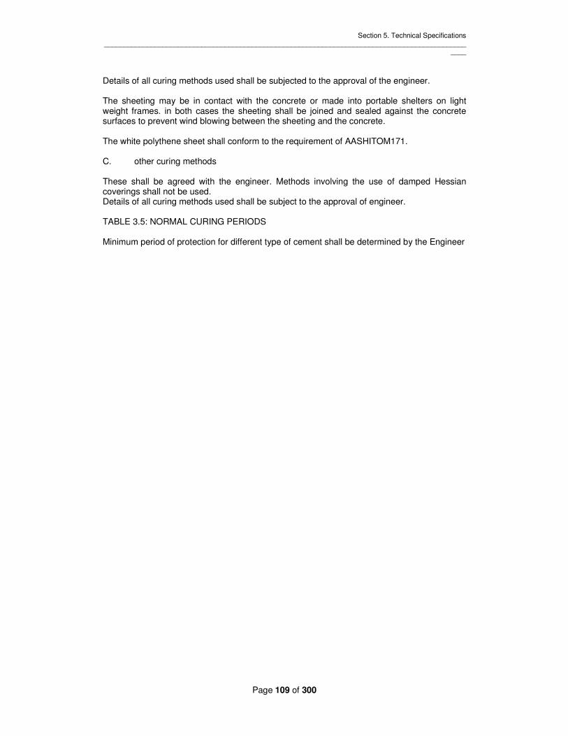
Section 5. Technical Specifications _____________________________________________________________________________________________
____
Page 109 of 300
Details of all curing methods used shall be subjected to the approval of the engineer. The sheeting may be in contact with the concrete or made into portable shelters on light weight frames. in both cases the sheeting shall be joined and sealed against the concrete surfaces to prevent wind blowing between the sheeting and the concrete. The white polythene sheet shall conform to the requirement of AASHITOM171. C. other curing methods These shall be agreed with the engineer. Methods involving the use of damped Hessian coverings shall not be used. Details of all curing methods used shall be subject to the approval of engineer. TABLE 3.5: NORMAL CURING PERIODS Minimum period of protection for different type of cement shall be determined by the Engineer

Section 5. Technical Specifications _____________________________________________________________________________________________
____
Page 110 of 300
Conditions under which concrete is maturing
Number of days(where the concrete exceed 10 deg C during the whole period
Equivalent maturity (deg c hours)(calculated as the age of the concrete in hours multiplied by the number of deg c by which the average tem of the concrete exceeds 10 deg c
Type IV Type IV or Type V
Type III Type IV Type I or V
Type III
1. Hot weather or drying wind
7 4 2 3500 2000 1000
2. Conditions not covered by 1.
4 2 1 2000 1000 500
Type IV – low heat Portland cement Type I – ordinary Portland cement Type III – rapid hardening Portland cement Type V – sulphate resisting Portland cement Hot weather – temperature over 16c. Where the thickness of concrete placed exceeds 1.5m, the contractor shall submit for the engineer’s approval proposals to ensure that, during the curing period:- the rate of rise of temperature in the concrete does not exceed 15’c per hour the first 3 hours: (b) Thereafter the rate of rise and fall of temperature in the concrete does not exceed 35’c per hours; the maximum temperature in the concrete does not exceed 70’c and the maximum difference in temperature between the core and the surface of the Concrete does not exceed 20’c. The proposals shall include consideration of:- concrete mix design; temperature of mix at time of placing; Method of curing. Where required by the engineer the contractor shall carry out temperature measurements in the concrete. The method and procedure of temperature measurement shall be agreed with the engineer. 305.10 Joints Construction joints the position of construction joints, when not shown on the drawings or otherwise required by this specification, shall be decided on site having regard to the plant and labour made available by the contractor for the manufacturer ,placing and compaction of the concrete as

Section 5. Technical Specifications _____________________________________________________________________________________________
____
Page 111 of 300
well as its curing the climatic conditions prevailing at the time of concreting, the nature and size of the formwork and the conditions of operation of the work, the contractor shall submit his proposals to the engineer for his approval before commencing the work. Construction joints surfaces shall be treated by the wash-off method explained below, except where it cannot be practically affected, in which case it shall be treated in accordance with clause 305.3 as for the placing of new concrete to hardened concrete. When expanded metal lTanathing is used for the formation of constructions joints a rebate will not be required to be formed. The expanded metal lTanathing shall be left in the work and shall not extend closer to the finished surface of the concrete than 25mm.it shall be securely fixed to the reinforcement. The following particular requirements shall also be observed:- Slabs supported on the ground In order to ensure control in the placing of concrete the contractor shall provide control boards to form panels not larger than 15m2 in area. These shall be lifted as the concreting proceeds expect where they are of expanded metal in which case they may be left in position as part of the permanent works, provided that they shall not extend closer to the finished surface Of the concrete than 25mm.in the event of a breakdown in the supply of the concrete the contractor shall ensure that an alternative supply of concrete is made available (to finish the work against the control boards acting as stop ends).the joint so formed shall then be treated as a construction joint. Where ready-mixed concrete is permitted (clause 307.4) the control board shall be positioned so as to Enclose a volume of concrete equal to that delivered by each truck. Construction joints and control joints shall be formed normal to the surface of the retained concrete. Suspended beams and slabs T-beams shall be formed to their full depth integrally with the adjacent slab and without horizontal joints. Walls Horizontal construction joints in walls shall be formed along straight lines coinciding with the full height of the form work. The height of the pour shall be determined with references to the availability of concrete, the size and amount of reinforcement and the means of compaction available. Unless otherwise indicated on the drawings or otherwise permitted by the engineer for the construction of circular tanks, concreting shall be carried out continuously for the use of vertical joints. Where permission is granted for the use of vertical joints the engineer ma order, at no extra cost to the employer, the inclusion of an approved type of water stop In the case of rectangular tanks, vertical joints shall not be positioned closer to any corner than one meter. They shall be formed with properly rebated stop ends or, where conditions permit, by the use of experienced metal lTanathing. Unreinforced manholes shall be constructed without vertical joints. (II) The “wash off method” of preparing construction joints. As soon as possible after concreting, and while the surface is still green, the surface of the concrete forming the joint shall be freed of loose aggregate and sprayed with a fine spray of water to prevent the formation of laitance. Subsequently all excess water shall be removed by a jet of compressed air and the surface left clean to receive further concrete.

Section 5. Technical Specifications _____________________________________________________________________________________________
____
Page 112 of 300
(III) Movement Joints These shall include contraction and expansion of joints and shall be as indicated on the Drawings. Contraction joints will be either full contraction joints or partial contraction joints. Where partial contraction joints are specified a period of at least five days shall elapse between the concreting of the section on each side of the joint. Where the Drawings indicated a contraction gap to be formed in any panel (this gap will not exceed one metre), concreting on either side of the gap shall be carried out so as to form partial contraction joints at each side of the gap. Prior to the concreting of the gap section, the joint surfaces shall be cleaned but otherwise left untreated. The concreting of the gap section shall not be carried out until a period of at least five days has elapsed after completion of the adjacent sections. Alternate panel construction (other than contraction gap construction outlined above) will be permitted only with the approval of the Engineer, or in those cases where either the reinforcement is not continuous through the joint or where the panels are separated by expansion or contraction joints. Unless otherwise specified or permitted by the Engineer all water stops shall consist of rubber or PVC. Jointing of waterstop shall be by vulcanizing except where PVC is specified or permitted in which case joints shall be by fusing or welding. Materials shall be obtained from an approved manufacturer whose recommendations as to jointing shall be fully complied with. (IV) Water stop and jointing Materials Water stop and jointing materials shall be obtained shall be obtained from an approved manufacturer. All water stop and jointing materials which are not required for immediate use shall be stored at all times in a cool damp place. Water stop shall be manufactured of rubber or PVC (polyvinylchloride) as stated in the Bill of quantities and shall be of the type and size shown on the Drawings. Site joints shall be made strictly in accordance with the manufacturers’ instructions and all intersections and junctions shall be obtained prefabricated from the approved manufacturer. Joint filler shall be manufactured of natural bonded cork or other approved material. Joint filler shall be cut and trimmed to suit the joint profile and shall be maintained accurately in position by means of an approved adhesive. Joint sealing compounds shall be approved rubber/bituminous compounds suitable for sealing joints in horizontal and vertical/sloping concrete surfaces as appropriate. Sealing compounds shall be applied strictly in accordance with the manufacturers’ instructions and shall completely fill the joint recess. Surface primers shall be from the same manufacturer as the sealants themselves. Water stop shall be located and maintained accurately in position and details of the proposed method of fixing shall be submitted to the Engineer for approval. On account shall water stop be secured by nails or by any other means involving puncture of or damage to the water stop material unless purpose made nailing flanges are incorporated in the design of the water stop. 305.11 Finishes –General All exposed faces of concrete unless otherwise specified shall be hard, smooth and free from honeycombing, air and water holes and other blemishes

Section 5. Technical Specifications _____________________________________________________________________________________________
____
Page 113 of 300
All projecting imperfections shall be rubbed down with carborundum stone or by other approved means a grit and dust there from shall be thoroughly washed off with clean water Surface finishes Wood float finishes shall be formed by smooth floating the accurately leveled and screeded surface. Care shall be taken to ensure that the concrete is worked on more than is necessary to produce a uniform surface free from screed marks. Steel trowel finishes shall be formed while the concrete is still wet by means of a steel trowel applied to an accurately leveled and screeded surface (see also Clause 307.3). Granolithic finishes shall conform to the recommendations laid down in “specification for granolithic floor topping laid in in-situ concrete”, as published by the cement and concrete association with special reference to monolithic construction. Screeded finishes shall be formed by leveling and screeding the concrete to produce a uniform, plain or ridged surface as specified. Bush-hammered or hammered or pattern-worked finishes. When exposed aggregate is to be the surface texture, the contractor shall ensure that a uniform distribution of the coarse aggregate takes place at the face. The formwork shall be removed as soon as possible from the face to be treated; the surface shall be thoroughly wetted and wire brushed ‘and bush-hammered or pattern0worked as and when instructed. Surface retarders shall be used only when permitted by the engineer Bush-hammering or pattern-working shall not be relied upon to obscure any defects in the concreting face which arise from shuttering imperfections. Making Good Honeycombed or damaged surfaces of concrete, which in the opinion of the engineer, are not such as to warrant the cutting out and replacement of the concrete, shall be made good as soon as possible after removal of the shuttering as follows:- 1:1.5 Portland cement and sand mixtures shall be worked into the pores over the whole surface with a fine carborundum float in such a manner that no more material is left on the concrete face than is necessary completely to fill the pores so that a uniformly smooth and dense surface of uniform color is finally presented. Removal and Replacement of Unsatisfactory Concrete The contractor shall on the Engineer’s instructions to do so cut out and replace any concrete in any part of the structure if in the Engineer’s opinion:- The concrete does not conform to the specification, or Deleterious materials or materials which are likely to produce harmful effects have been included in the concrete, or The honeycombed or damaged surfaces are too extensive, or The finished concrete sizes are not in accordance with the drawings with in permissible tolerances, or The setting-out is incorrect, or The steel cover has not been maintained, or The protection, including curing , of the concrete during the construction was inadequate, resulting in damage, or The work of making good or other remedial measures the Engineer may indicate are not carried out to his satisfaction, or Undue deformation of or damage to the works has taken place due to inadequate shuttering, or to premature traffic or to excessive loading , or Any combination of the above points has taken place resulting In unsatisfactory work TESTING Sampling and Testing (See also Clause 301 and 302.4)

Section 5. Technical Specifications _____________________________________________________________________________________________
____
Page 114 of 300
The Contractor shall provide on the site equipment, staff and labor for carrying out the sampling and testing outlined in columns 3 and 4 of table 3.6, and he shall carry out any or these entire test at such times and with such frequency as may be requested by the Engineer. All the equipment shall be calibrated and checked from time to time as the Engineer may require. The contractor shall provide all samples required by the Engineer. Those samples to be tested in an off-site laboratory shall be carefully forwarded by the contractor to an approved laboratory. Results of laboratory and site tests shall be kept on site and copies of all test report shall be forwarded in duplicate to the Engineer’s Representatives. Frequency of tests and the number of samples required will be governed by the results of the previous tests, and the quality of the materials revealed during the tests, the uniformity of that quality (see Clause 302.4). Should it become evident that the quality of concrete is deteriorating the Engineer may require additional samples to be taken and tests cubes to be made and tested to determine the cause. Loading Tests The Engineer may direct that a loading test be made on the works or any part thereof if he deems such test to be necessary for one or more of the following reasons :- Failure of “Site Cubes” to attain the strength requirements of Clauses 302.2 and 302.4; Premature removal of formwork ; Overloading of structure during construction; Improper compaction and/or curing of concrete; Any other circumstances attributable to alleged negligence on the part of the contractor , which in the opinion of the Engineer, may result in a structure being of less than a required strength; If the loading test be ordered to be made solely or in part for reasons (a) to (d) the test shall be made at the contractor’s own costs. If the loading test to be ordered to be made for a reason (e), the Contractor shall be reimbursed for the cost of the test if the result is satisfactory. Loading test shall be carried out in accordance with the requirements of BS 8110. If the results of the test are not satisfactory, the Engineer will direct that the part of the work concerned be taken down or removed and reconstructed to comply with the Specification, or that such other remedial measures as the may think fit be taken to make the work acceptable and the contractor shall carry out such work at his own cost. The Engineer may also instruct the contractor before a loading process test takes place to take out cylindrical core specimens from the structures concerned and have them tested. The cutting equipment and the method of doing the work shall be to the Engineer’s approval. The specimens shall be dealt in accordance with BS 1881. Prior to testing, the specimens shall be available for examination by the Engineer .If the cores are ordered to be taken solely the Engineer. If the cores are ordered to be taken solely or in part for reasons (a) and (b) above, the work involved and the testing shall be made at the Contractor’s own cost. If the cores are to be taken for reasons (b), (c) and (e) above, the Contractor will be reimbursed the cost if the loading test described in the previous paragraphs proves satisfactory. SPECIAL CONCRETE No-fines Concrete No-fines concrete for use in subsoil drainage shall consist of a 1:8 cement/ aggregate mix by volume. Aggregate shall be 20mm to10mm graded with no more than 5% passing the 10mm sieve. Only sufficient water shall be added to ensure complete coating of the aggregate. One half of this water shall be placed into the mixer first, after which the aggregate and cement

Section 5. Technical Specifications _____________________________________________________________________________________________
____
Page 115 of 300
shall be admitted. After partial mixing the balance of the water shall be added until a constituency of mix is achieved. Preliminary tests shall be carried out on the site to prove the suitability of the finished concrete, and adjustments made to proportions and or grading as may be required by the Engineer. Air-Entrained Concrete Concrete for roads and those structures where specified, shall include an approved air-entraining agent capable of producing a 5% air-entrainment with a tolerance of 0.5% (Clause 302.9). The mix shall be purposely designed, having regard for the nature of grading of the aggregate and air-entraining agent being used. Preference shall be given to the use of air-entraining agent which can be administered in fixed calibrated amount through a dependable mechanical dispenser or sachet, and which is added to the mixing water. Frequent air meter tests shall be carried out and the constituency of the air-entrainment maintained to the above tolerance by adjustments in the mix, as may be necessary. Concrete in Benching Concrete for benching in manholes, pumping stations and works structures shall consist of grade C20P concrete unless otherwise specified. It shall be placed with low workability to the approximate shape required and, while still green, shall be finished with not less than 50mm of Grade C20P concrete to a steel trowelled finish and to the contours indicated on the drawing. Ready Mixed Concrete Unless otherwise stated the relevant clauses of BS 1926 shall apply. Ready mixed concrete shall only be used with the prior approval of the Engineer. The Contractor shall not be relieved of this obligation to provide concrete to the standard laid down in this specification by virtue of any approval given for the use of concrete supplied by others, and the Engineer reserves the right to withdraw his approval at any time consequent on any deterioration in the quality of the concrete, or unsatisfactory delivery or any other reason he considers detrimental to the works, Ready mixed concrete manufactured off the site shall be transported in a revolving drum and shall be continuously agitated until it is used in the work unless otherwise approved. The time interval between adding water to the drum and placing shall not exceed 90 minutes. The time interval between completion of mixing and placing shall comply with Clause 305.3. Granolithic Concrete Refer to Clause 305.12. Pneumatically Applied Mortar (Gunite) Requirements The pneumatic application of mortar shall be carried out only by Contractors experienced in this type of work and who are in possession of proper plant and equipment. Nozzle men employed on the works shall be skilled operators. The finished product shall be dense, of even texture a color, and to the requirements of the strength, tolerance and finish set out in this Specification. Strength After curing, the mortar shall be capable of producing cored samples with a 28-day characteristic strength of not less than 27.5 N/mm2.

Section 5. Technical Specifications _____________________________________________________________________________________________
____
Page 116 of 300
Materials Sand, cement and water shall comply with the requirements of clauses 302.6, 7 and 8 of this Specification except that the sand shall conform to the grading of Zone 2 of BS 882. Proportions The proportions to be used in mix shall be determined with reference to the requirements outlined in sub-clause 307.6(i) and the mix shall be not weaker than one part of cement to four parts of sand by volume, having regard to the adjustments for bulking of the sand. Operation Air and water pressure shall be such as to permit of the proper application of the mortar, and shall be determined with reference to those lengths and nozzle diameter. Rebound, recovered, cleaned and uncontaminated with extraneous matter, may be re-used but not for water-retaining structures. It shall be regarded as an equivalent volume of sand which shall not exceed 20 per cent of the total sand requirement. Rebound which has lodged in the shuttering or between reinforcement shall be removed by compressed air. Reinforcement shall be completely embedded n the mortar by the proper direction of the nozzle and the mortar shall be applied as a steady and uninterrupted flow from the nozzle. Mortar application shall be discontinued at any section of the work where sagging of the mortar is in evidence. Joints These shall be formed by sloping the surface to a thin edge. Before applying new mortar, the surface shall be thoroughly wetted. Laitance shall be removed by the initial discharge of fresh mortar. Tolerances The thickness of applied mortar shall be not less than the dimensions neither shown on the drawings nor greater than 10mm over those dimensions, unless otherwise indicated on the drawing or otherwise permitted Protection and Curing Shall be carried out in accordance with the requirements of clause 305.9. Finishes Unless otherwise specified all surface shall be brought to a granular textured finish by means of wooden float. Cold Weather Work No application of mortar shall be made against frozen surfaces or when the air temperature is below 50C. Making Good Any defective work shall be cut out immediately and made good with fresh mortar pneumatically applied. Pumped Concrete Where pumping of concrete is permitted to be used no relaxation of the requirements of this specification will be permitted. Particular attention shall be paid to the proper grading of aggregates to prevent bleeding and/ or segregation during the pumping operations. The
Section 5. Technical Specifications _____________________________________________________________________________________________
____
Page 117 of 300
inclusion of water-reducing additives or other materials, including fly ash, to improve the flow characteristics of the concrete will only be permitted where it can be shown that they do not adversely affect the concrete either in the plastic phase or in the finished work. PRECAST CONCRETE Requirement Precast concrete units, unless otherwise stated, shall be obtained from an approved manufacturer and shall be true to dimension and shape, with true arrases and with perfectly smooth exposed faces free from surface blemishes, air holes, crazing and other defects, whether developed before or after building-in. they shall comply with the appropriate BS.(Note: coping blocks and similarly exposed units are particularly susceptible to crazing when the concrete is manufactured using high water/ cement ratios. The requirements of table 3.1 shall be rigidly adhered to on all occasions therefore, and where units are supplied by others, the Contractor shall inform the supplier of these requirements). In addition, the requirements outlined in Clauses 308.2 to 308.8 inclusive particular to the various units shall be complied with. Weir Blocks and Sills Aggregate for the making of weir Blocks and sills shall conform to BS 1201, except that the use of soft or weathered limestone course aggregate will not be permitted. Fine aggregate shall consist of sand resulting from the natural disintegration of rock. Blocks and sills shall be tested for water absorption in accordance with BS 340 and shall display neither greater absorption than 2.5% after 10 minutes nor 6.5% after 24hours immersion, the percentage being based on the dry weight of the test pieces. In addition, they shall exhibit no visible signs of distress when subjected to an approved freeze-thaw test based on thirty cycles of exposure. After such a test the compressive strength of the test piece shall be not less than 80% of the strength of a similar piece which has not been subjected to the test. Weir blocks shall be ground to a polished surface on the upper and discharge faces. Coping Blocks and Weir Blade Holders These units shall conform to the requirements for weir blocks stated above but without polishing shall be brought to a smooth surface on the exposed faces. Coping blocks of thickness 60mm or less shall be formed by pressing, by employing pressures not less than 6.5N/mm2 over the entire surface receiving the pressure, before being brought to the required finish. Kerbs Precast concrete kerb shall conform to BS 340, except that coarse aggregate shall conform to BS 1201. Fine aggregate shall consist of sand resulting from the natural disintegration of rock. Approved air-training agents may be permitted to be used providing that approved adjustments are made to the mix with regard to water and fine aggregate proportions (Clause 302.9). in such cases the moisture absorption limits set out in BS 340 may be neglected subject to the concrete satisfying the freeze-thaw test laid down under the heading “Weir Blocks and Sills”. Paving Slabs Paving Slabs shall conform to BS 368 and shall be 50mm thick unless otherwise specified. Other Blocks

Section 5. Technical Specifications _____________________________________________________________________________________________
____
Page 118 of 300
Blocks used for building work and filter bed walls shall conform to BS 1364/ BS 2028. Wall Units L-shaped wall units shall conform to the requirements of CP 116. Where it is not intended to use coping blocks for the protection of the upper exposed surface of the units, the uppermost 150mm, for the full width of the unit, shall be formed with concrete composed of aggregate complying with the main body of the concrete Other Items Manhole ring units, tapers, cover slabs, segments and concrete pipes are referred to under their particular heading. SITE BOOKS AND STANDARDS Instruction to be Recorded The contractor shall provide and keep permanently on the Site a number triplicate book wherein the contactor shall record all instructions relating to concrete work issued by the Engineer or the Engineer’s representative. One copy of every entry therein shall be sent to the Engineer on the same day as the entry is made. Site Diary The contractor shall provide and keep permanently on the Site a continuous entry diary wherein the Contractor shall record details of shuttering, construction, placing of reinforcement, concreting and curing operations, striking of shuttering, making good and daily temperature and weather conditions. This diary shall always be available for inspection by the Engineer or the Engineer’s Representative. Copies of Standards and Codes The contractor shall provide and keep permanently on the Site copies of the following British Standard Codes of practice:- BS 812 BS 882 BS 1478 BS 1881 BS 8110 BS 8007 BS 5328 The Contractor shall in addition provide and keep permanently on the Site copies of such other standard codes. Notes and Specifications as may be required by the Engineer. WATER RETINING STRUCTURE S – SPECIAL CLAUSES Note: In the event of any differences between the “special clauses” and the earlier clauses of the specification under Section 3 then the provisions of these “Special clauses” shall have precedence. Making Good The cement mortar used in filling recesses in the concrete formed by bobbins in connection with shuttering shall contain an approved expanding admixture Construction Joints In Water Retaining Structures

Section 5. Technical Specifications _____________________________________________________________________________________________
____
Page 119 of 300
In water retaining structures PVC water stops not less than130mm wide manufactured by an approved manufacturer shall be built into all construction joints in floors all vertical construction joints in walls which are exposed externally and construction joints in roofs of potable water retaining structures. Construction joints shall be formed at positions agreed by the Engineer. The cost of forming construction joints shall be included for by the Contractor in his general concrete rates. Water tightness of Structure The Contractor Shall is solely responsible for the water tightness of structures and any remedial measures necessary. TESTING OF WATER-RETAINING STRUCTURES All water-retaining structure shall be tested for water-tightness on completion in the following manner. The structure shall be filled with clean water in stages of one meter and held at each water level for such time as the Engineer may require. Should any dampness or leakage occur at any stage, the water shall be drawn off and the defects remedied to the satisfaction of the Engineer. The procedure shall be continued and finally the structure shall be allowed to remain full for three days or such other period as the Engineer may decide to allow for absorption, followed by a period of seven days during which the total permissible loss of water, after allowing for evaporation, shall not exceed 1/ 1000 of the capacity of the structure. Not Withstanding the satisfactory completion of the seven days test, should any dampness or leakage or other defects occur they shall be made good to the satisfaction of the Engineer and the structure re-tested until the water-tightness is approved by the Engineer. The Contractor shall provide a book gauge to measure variation in the water level during the tests. The testing shall be carried out before the excavations are backfilled and embankments placed. In the case of potable water reservoirs and tanks the roof shall be tested for water-tightness by flooding (in small areas at a time if necessary) to a minimum depth of 25mm. The water shall be left standing for not less than 24 hours and the underside of the roof shall be examined for dampness or leakage. Any defects shall be made good by the Contractor and the tests continued until the water-tightness of the roof is approved by the Engineer. Where it is not practicable to contain a depth of 25mm of water over the roof, the roof shall be thoroughly wetted by continuous hosing for a period of six hours. The Contractor shall be solely responsible for the water-tightness of structures and any remedial measures necessary. The water used for testing shall be provided at his own expenses by the Contractor and shall be free from impurities and of such quality which will not pollute or impair the water-retaining structure. The Contractor shall give the Engineer’s representative at least 14 days notice as to the source of water intended for use for testing purposes. The Contractor shall be solely responsible for making all arrangements necessary for obtaining water and provision of testing water retaining structures. CLEANSING AND STERILIZING WATER-RETAINING STRUCTURES The inside of all potable water-retaining structures and all interior pipe work and fitting shall be thoroughly cleaned and washed after the water-tightness test has been approved by the Engineer to remove all contamination and the water from these operations shall be removed by sequence and drained away.

Section 5. Technical Specifications _____________________________________________________________________________________________
____
Page 120 of 300
The internal surface of the structure shall then be thoroughly washed with clean water containing 20 parts per million Chlorine. The chlorinated water shall then be drained away and the structure filled with potable water from which, after 24 hours, samples shall be taken for analysis to the instruction of the Engineer. If any of the results of the analysis are unsatisfactory when compared with those of the control sample of the supply water the sterilizing process shall be repeated until the result of the test are satisfactory. The cost of the initial sampling analyses and preparing reports on the bacteriological quality of the water shall be borne by the employer but should initial reports be unsatisfactory the cost of any subsequent sampling analyses and preparing reports shall be borne by the Contractor.

Section 5. Technical Specifications _________________________________________________________________________________________________
Page 121 of 300
TABLE 3.6 SAMPLING, TESTING, AND ACCEPTANCE STANDARDS
Materials Test Site
Sampling Testing
Acceptance Standards
Remarks
1 2 3 4 5 6 Cement Ordinary Portland
Rapid hardening Sulphate resisting
BS 4550 BS 12 BS 12 BS 4027
Manufacturers Test certificates
Aggregates Description and Classification
BS 812 Sec.2 BS 882 or 1201 Whichever is applicable
Particle Size BS 812 Sec.1 BS 812 Sec.3 BS 882 or 1201) Particle shape BS 812 Sec.1 Visual+
BS 812 Sec.3 ) )
Sp. Gravity BS 812 Sec.1 BS 812 Sec.3 ) Mix design Density BS 812 Sec.1 BS 812 Sec.3 ) Requirement Voids BS 812 Sec.1 BS 812 Sec.4 ) Absorption BS 812 Sec.1 BS 812 Sec.4 BS 8007 C1.
6.2.2 See freeze-thaw Test this table
Organic Impurities BS 812 Sec.5 Moisture content BS 812 Sec.5 For Adjustment of added
water for concrete making Mechanical properties BS 812 Sec.6 BS 882 or 1201 Ten per cent fine value

Section 5. Technical Specifications _________________________________________________________________________________________________
Page 122 of 300
TABLE 3.6 SAMPLING, TESTING AND ACCEPTANCE STANDARDS (Contd)
Materials Test Site
Sampling Testing Acceptance
Standards Remarks
1 2 3 4 5 6 Water Suitability BS 3148 BS 3148 BS 3148 Not required for
potable water Concrete Compacting factor)
Slump ) BS 1881 Pt. 101
BS 1881 Pt.103 BS 1881 Pt.102
) )
Workability test
Crushing BS 1881 BS 5328, BS 8110 Cube Test Water absorption BS 1881 Pt. 122 BS 340 Para 19 (b) Precast Concrete C1.
308 Freeze-thaw BS 1881
Pt. 101 Durability test for
aggregate not complying with moisture absorption requirements of BS 5337 C1.21.2
Electrolytic Efflorescence
As required for salt containing aggregate or saline water
Cores BS 1881 Pt.6 BS 1881 Pt. 120
BS 1881 Pt.6 BS 1881 Pt. 120
BS 1881 Pt.120 with ref. to Concrete strengths this specifications
See Clause 306.2
Admix Compatibility with Cement
As required by laboratory Test to be carried out by independent laboratory as required

Section 5. Technical Specifications _____________________________________________________________________________________________
____
Page 123 of 300
SECTION 4- UNDERGROUND WORKS INDEX GENERAL DEFINITIONS EXPLORATORY DRILLING AND GEOLOGICAL LOGGING Core Drilling Advance Probe Drilling Geological Mapping METHOD OF CONSTRUCTION OVERBREAK UNDERGROUND BLASTING RAIL TRAFIC SUPPORT Permanent Support Temporary Support SHOTCRETE General Materials Accelerating Admixtures Mix Design And Testing Equipment And Operator Preparation Of Surface And Application Reinforcement Gunite ROCKBOLTS General Resin Grout Installation Tensioning Proof Test Inspection STEEL RIBS CONCRETE LINING General Mix Design Suitability Of Proposed Mix Proportions Concrete Construction Reinforcement Tolerances Recording Information NOT USED GROUTING BEHIND CONCRETE LINING General Grouting Procedures Contact Grouting Rock Consolidation Grouting Acceptance Testing Reinstatement Records FORWARD GROUTING IN TUNNEL GENERAL GROUTING PROCEDURES ACCEPTANCE TESTING RECORDS INSTRUMENTATION CONVERGENCE MEASUREMENT SYSTEM EXTENSOMETERS WIRIING AND LIGHTING

Section 5. Technical Specifications _____________________________________________________________________________________________
____
Page 124 of 300
DANGEROUS GASES AND DUST VENTILATION PROFILING CONTRACTOR’S WORKMEN PROTECTIVE CLOTHING DISPOSAL OF EXCAVATED MATERIAL SAFETY

Section 5. Technical Specifications _____________________________________________________________________________________________
____
Page 125 of 300
SECTION 4- UNDERGROUND WORKS 401 GENERAL In the event of any discrepancy between this section and clauses elsewhere in the specification this section shall have precedence. 402 DEFINITIONS The “underground works” shall comprise: Spillway shaft and tunnel Draw-off and diversion tunnel Draw-off shaft Drainage Adits A “pay Line”, a “design inside profile” and a”nominal Shotcrete line” are shown on the drawings at specified distance from the centre line of the tunnel. Their relevance to measurement and payment is defined in the “preamble to the Bill of Quantities”. “Over break” shall mean any falls, slips of material or over-excavation beyond the pay line. “Permanent support” shall be that support specified by the Contractor and provided for in the measurement and payment defined in the bill of quantities. “Temporary support” shall be that support required by the Contactor to maintain the tunnel portals and underground excavation in a stable and safe condition until the installation of the permanent support or structure. The cost of the temporary support is deemed to be included in the Contractor’s rates for excavation. “Maximum unsupported Span” shall be that length of underground excavation in any direction where the roof the excavation may remain unsupported at any one time by the permanent support in each rock mass class or location defined on the drawings. In order to suit this method of working the Contractor may increase this length by the use of temporary support at the discretion of the Engineer. EXPLORATORY DRILLING AND GEOLOGICAL LOGGING Core Drilling The Contractor shall carry out exploratory drilling in the underground works as directed by the Engineer in accordance with Clauses 501 to 506 inclusive. The drilling equipment used shall be capable of drilling to a maximum rock core diameter of 76mm and to a length of at least 30m at any angle. Advance Probe Drilling At all times during tunnel excavation the Contractor shall maintain cover which extends at least 3m beyond the limit of the face advance by drilling 1 No. probe hole in the crown. Alternatively in areas where ground water is suspected or as directed by the Engineer the Contractor shall drill 2 No. probe holes in the crown , one on each side of the centre line, extending not less than 12m forward of the face to ascertain the extent and location of water bearing strata. The probe holes may comprise extensions to the smooth blasting peripheral holes being of the same diameter and orientated at the appropriate “look out angle”. The holes may later be stemmed and utilized in the smooth blasting round, for this purpose, shall be to the approval of the Engineer.

Section 5. Technical Specifications _____________________________________________________________________________________________
____
Page 126 of 300
Should Advance probe drilling intersect ground water under significant pressure such that continued tunnel advance is hazardous then the water shall be drained by these and additional holes drilled in the face until the ground water pressure has been reduced sufficiently to allow the safe advance of the tunnel face. The pressure of water issuing from probe holes shall be monitored by the installation of an inflammable packer type stand pipe into each probe hole. Each stand pipe shall be provided with a‘t’ piece of similar gauge diameter with 2 no. relief valve to the outlets one of which can be attached to a suitably rated manometer to read the water pressure. At least 5 no. stand pipes and at least 2 no. manometer in good working condition shall be available at all times on site during tunnel excavation. Where the ground a head of the tunnel is shown to be unstable by the advance probe drilling or the pressure and flow of water issuing from the advance probe holes does not reduce over a 24 hours period with the drilling of additional probe holes, such that the tunnel can be advanced safely, then the Engineer, in consultation with the Contractor, may require forward grouting to be carried out. The Contractor shall submit to the Engineer at the beginning of each day a daily report of groundwater encountered during tunneling both from the advancing tunnel face and the advance probe holes. The records shall detail the location, pressure and estimated flow rates of each source of water and shall be presented in a form to the Engineer’s approval Geological Mapping On completion of blasting, Scaling, removal of excavated material and installation of temporary supports, and before drilling for charging the next blasting round commences the exposed rock face shall be cleaned by jetting with water under pressure. The newly excavated portion of the underground excavation shall then be inspected and geologically logged by the Contractor’s qualified geologist, in the presence of a geologist on the Engineer’s representative’s staff. This shall comprise a detailed examination of the face, crown and side walls for the purpose amongst other things of determining the rock mass class. The geologist shall prepare a detailed graphic and descriptive log in the form of a developed plan of the tunnel side walls and crown and profile of the tunnel face. A draft of the complete log to A3 size shall be submitted to the Engineer for his approval not later than 24 hours after completion of the inspection. The form of log shall be submitted for the shaft excavations. The geological log shall include Changes in lithology and degree of weathering, locations, estimates and measurements of groundwater inflow, the location type condition and orientation of major discontinuities, fissures and shear zones, an assessment of ROD and Q values of the exposed rock and the rock mass class identified in accordance with the classes stated on the drawings. Where the Engineer fails to agree with the Contractor’s assessment of rock mass class, the Engineer’s assessment shall prevail. In addition to the geological logs described above, the Contractor shall keep on site a continuous geological record of the underground excavation which shall be regularly updated from the approved log sheets. The record shall also contain a summary and show geological sections across the tunnel at approximately 10 meters intervals. The geological record shall be available for inspection by the Engineer. Three copies of all geological records including the final log sheets shall be submitted to the Engineer in the form

Section 5. Technical Specifications _____________________________________________________________________________________________
____
Page 127 of 300
of a report within 3 months of completion of each underground excavation. The form of the report shall be to the approval of the Engineer. METHOD OF CONSTRUCTION The Contractor shall submit to the Engineer for his review 84 days before construction is commenced a full statement of the methods he proposed to adopt for the construction of the underground works including general and detailed drawing of all temporary supports together with relevant calculations. Such details and proposals shall comply with the general requirement of this specification. No approval or agreement to such proposal (or subsequent amendments thereof) given or made by the engineer or any failure on the part of the Engineer or his representative to order support or additional support to excavations shall relieve the Contractor of his responsibilities for the safety of the work and the workmen or for any slips, falls or consequent filling which may be required. The underground works shall be constructed to the line and levels Shown on the drawings. The Contractor shall be responsible for setting out and all survey work necessary. Details of the proposed setting out and alignment control methods shall be included in the method statement referred to above. The Contractor shall provide temporary adders to all shafts with landings at intervals not exceeding 6m. Protection shall be so provided that neither the ladders, landings or supporting structures nor persons using them are subjected to the risk of damage or injury by the passage of skips and/ or materials in the shaft. After the primary lining is complete in a shaft and before any openings are made at or near the foot, the excavation for the base of the shaft shall be taken out and the base concreted. OVERBREAK The excavation shall be carried out with all care so as to avoid excessive overbreak. Surface of excavation shall be properly trimmed. Voids caused by falls or slips of materials or by over-excavation shall be filled with Shotcrete or grade 15 concrete placed concurrently with the permanent lining. UNDERGROUND BLASTING Blasting in underground excavation shall comply with the requirements of Clause 214of this specification. The Contractor shall during the excavation of the underground works take every precaution, including the cessation of excavation by blasting, to ensure the safety not only of the works under construction, but of the completed work, and the ground surrounding it. The Engineer shall have the right to decide whether blasting shall continue to be used in the excavation of the underground works and not withstanding any approval he may give or any decision he may make, the safety of persons, structures, excavations and surrounding properties shall remain solely the responsibility of the Contractor. Electric blasting shall not b permitted when lightening is possible. All necessary precaution shall be taken to minimize disturbance of material and structures, included in and adjacent to the permanent and temporary supports shall be rectified and material which is loosened by blasting shall be removed to the satisfaction of the Engineer’s Representative before the next blasting round. The perimeter of the underground excavations (with the possible exception of the invert) shall be formed by controlled blasting techniques including smooth blasting and pre-splitting.

Section 5. Technical Specifications _____________________________________________________________________________________________
____
Page 128 of 300
Perimeter contouring holes for smooth blasting shall be drilled and charged at the same time as those for the main blasting. The contouring holes shall be fired last in the delay sequences. RAIL TRAFFIC In the event of the Contractor wishing to operate rail traffic in tunnels a separate method statement shall be included with the tender who shall cover all aspects of constructing and operating such a system with particular attention to all aspects of safety. The rail system shall follow the general guidelines given in this specification and be in accordance with current Kenyan rules and regulations on the rail traffic systems. The motors of all locomotives operating in tunnels shall comply with other relevant clauses of this specification relating to the use of electricity and internal combustion engine in tunnels. Every locomotive shall be provided with:- Effective brakes which can be applied by the driver. A mans of giving audible warning of approach. Light at rear (red) and front (white). If any of these items is defective the locomotive shall be taken out of service until the fault has been rectified. Rail track shall be soundly constructed so that no movement occurs under traffic. Sleepers shall be placed at regular intervals of approximately 900mm. the Contractor shall maintain the track in good condition to avoid derailments as far as is practicable. If any delays to the supply of concrete occur due to derailment, the Contractor shall suspend concreting operations while track maintenance is carried out to the satisfaction of the Engineer. Arrangement shall be made for refueling or recharging the batteries of locomotives to be carried out outside the tunnel, except where such arrangement is impracticable. SUPPORT Permanent support Where permanent support is required it shall comprise: Shotcrete Shotcrete with steel fabric reinforcement Rockbolts Steel Ribs with or without steel lagging and invert Structs Steel, precast concrete packing and metal wedges Mass concrete Reinforced concrete The location, extent and construction of the permanent support shall be generally as shown on the drawings or as otherwise indicated by the Engineer. Temporary Support Particular attention is drawn to the need to provide support as soon as practicable after excavation. If the contractor’s chosen method of working is such that he cannot install the permanent support immediately then he shall maintain the excavation in a stable condition by means of installation of temporary support until the permanent support is constructed. Where temporary support is required it may comprise: Shotcrete Shotcrete with steel fabric reinforcement Rockbolts Steel Ribs with or without steel lagging

Section 5. Technical Specifications _____________________________________________________________________________________________
____
Page 129 of 300
Precast concrete arches and packing Shield Crown bars Forepolling Other to the approval of the Engineer Items of Temporary Support may be considered for inclusion in the Permanent Works where appropriate subject to inspection and verification of their integrity and at the discretion of the Engineer. Temporary Support which does not impede the installation of the Permanent Works and shall not have any deleterious effect on the Permanent Works may be left in place at the discretion of the Engineer. Otherwise all Temporary Supports shall be removed from the site immediately prior to or during installation of him Permanent Support at no additional cost to the Contract. SHORTCRETE 409.1 General “Shortcrete” for the purpose of this Contract shall be defined as a Portland cement concrete applied on to the excavated surface from a nozzle by compressed air. Unless agreed otherwise by the Engineer the shortcrete shall contain an approved admixture to achieve a quick set and high early strengths as specified below. Shortcreting shall be carried out generally in accordance with recommendations of the American Concrete Institute Standard “Recommended Practice for Shortcreting” (ACI 506-66) or other equivalent approved standard. Materials Cement, aggregates and water shall comply with the requirements of specification Section 3 – Concrete. Cement shall be Ordinary, Sulphate-Resisting or Rapid-hardening Portland complying with requirements of BS 12 or BS 4027. Each consignment shall be identified, stored in dry conditions and used in order of manufacture. Coarse and fine aggregates shall be from either crushed rock or natural resources, and comply with the requirements of BS552 Part 2, and have a maximum nominal size of 20mm or one third of the diameter of the smallest constriction in the delivery system whichever is the smaller. Steel or other fibers shall be used only with the approval of the Engineer and shall be from a manufacturer approved by the Engineer. Accelerating Admixtures An accelerating admixture complying with the requirements of BS 5075: Part 1 and to the approval of the Engineer shall be used to enable the shortcrete as applied to develop a quick initial set and high early strength. Subject to the agreement of the Engineer’s Representative the accelerating admixture may be reduced or omitted where conditions are such that quick setting properties are not required, provided that the lining is then left undisturbed until it has hardened. The contractor shall submit for the approval of the Engineer the amount of the admixture to be added to the shortcrete mix, the method of use including the chemical names of the main active ingredients in the admixture and the reason why the use of the admixture is

Section 5. Technical Specifications _____________________________________________________________________________________________
____
Page 130 of 300
being proposed. The detrimental effects, if any, of under-dosage or over-dosage shall be established particularly in relation to durability throughout the service life of the works. The information scheduled in BS 5075, Clause 7 shall be provided. Admixtures shall be used in accordance with the manufacturer’s instructions and shall be incorporated through a dispensing system sufficiently accurate to deliver within +- 5 % of the approved dosage rate. No admixtures containing calcium chloride shall be used. Mix Design and Testing Mix proportions shall be designed by the Contractor but shall contain a maximum cement content of 20%, a minimum coarse aggregate content of 30% and a maximum fine aggregate content of 50% by weight. Weight batching shall be employed. The accuracy of the weight batching shall be within +- 3%. The design of the mix shall be such that the equivalent cube strength shall be 30 N/mm2 minimum at 28 days, No material other than oven dried or bagged pre-mix shall be used later than one hour after the addition of cement to the aggregate. All constituents shall be uniformly dispersed throughout the mix. Where admixtures are approved by the Engineer for addition to the mix to speed the setting times and strengths shall apply. Initial set of cement/admixture paste 3 minutes maximum Final set of cement/admixture paste 12 minutes maximum 8 hour strength of Shotcrete 4N/mm2 minimum 24-hour strength of Shotcrete 10N/mm2 minimum Preconstruction testing shall be carried out well in advance of the start of construction of the underground works using plant identical to that proposed for the Works and shall be undertaken in such time before commencement of the work to allow approval by the Engineer. Trial mixes of each mix design proposed shall be produced by the contractor. For each mix design or for each type of plant, 3 no. test panels of minimum size 750mm * 750mm * 100mm thick shall be sprayed both in the down hand and overhead positions, as required in the works. Panel moulds shall be formed from plywood at least 20mm thick, be adequately braced and be held rigidly in position. During construction of the underground works and where required by the Engineer, the contractor shall provide moulds for unreinforced test panels 750mm * 750mm * 100mm thick rigidly fixed alongside the work in positions and numbers as may be required by the Engineer. At least one test panel will be required for every 10m3 of Shotcrete placed. The moulds shall be sprayed at such times and from such batches and by such personnel as the Engineer may direct. The test panels shall be stored and cured alongside and under similar conditions to the Shotcrete in the works. 4 no. 100mm dial. Cores shall be cut from each test panel at right angles to the plane of the panel approximately 48 hours after the panel has been sprayed. Cores shall not be taken within 125mm of the edges of the panel. 1 no. core shall be compression tested at 3 days, 1 no. core at 7 days and remaining 2 no. cores at 28 days. Cores shall store, cured and tested in accordance with BS 1881: Part 4. The cores shall be suitably labeled to identify them with the panels from which they have been taken and the location in the works to which they relate. The appropriate compressive strength requirement for each set of 2 no. 28 day cores shall be satisfied if: Each core has an estimated 150mm cube strength as defined by BS 1881: Part 12 equal to or greater than specified, or

Section 5. Technical Specifications _____________________________________________________________________________________________
____
Page 131 of 300
The average estimated cube strength is equal to or greater than that specified and the difference between the strengths is less than 20% of the average. Should any of the cores reveal defects such as a lack of compaction, dry patches, voids or sand pockets, the Engineer may require further tests or cores to be taken front the remainder of the panel(s) or further panels made. Where required by the Engineer, 10mm dial. Cores shall be taken by the Contractor from Shotcrete placed in the Permanent Works in positions selected by the engineer to determine thickness and quality of the Shotcrete. Where required by the Engineer, sets of three Windsor Probe readings shall be taken by the Contractor in the presence of the Engineer’s Representative on the finished Shotcrete at positions indicated by the Engineer, in order to assess the in situ compressive strength. Approximately 1 set of readings will be taken for every 30sq. meters of Shotcrete. Calibrations of the Windsor Probe shall be carried out by taking sets of readings on the preconstruction test panels at the same time as the core crushing tests. Copies of calibration and Windsor Probe readings shall be submitted to the Engineer for each day’s work, during the following day. Core holes shall be filled by hand with well rammed dry-packed concrete of similar mix to that used for Shotcrete or with suitable resin mortar to the approval of the Engineer. The setting times of the cement/admixture paste shall be determined by using the Vicat apparatus in accordance with BS 4550: Part 3: Section 3.5. Equipment & Operators Shortcreting equipment, pumps, hoses, nozzles, etc. shall conform to normal modern Shortcreting practice. The air supply shall deliver air at constant pressure and uncontaminated by oil or other deleterious matter. The system shall be arranged so that air and water may be used in any combination for the preparation of surfaces on which Shotcrete is to be placed. Prior to commencement of spraying, the Contractor shall certify to the Engineer that the foreman, nozzle men and delivery equipment operatives have completed satisfactory work in similar capacities elsewhere. Where required by the Engineer the operators shall spray preconstruction panels which shall be approved by the Engineer before the operators are employed on the Works. Such panels may also be used by the engineer to assess the competence of operators or trainees for whom such certification is not available. Preparation of Surfaces and Application Immediately prior to placing the Shotcrete lining the surface, whether new or previously Shotcrete, shall be cleaned by high pressure air/water jet to remove all loose material, mud and other foreign matter and exhibit no free water prior to the application of Shotcrete. Where flow of water could interfere with the application of Shotcrete or cause leaching of cement, the water should be led by pipes or gutters to some point where it may be plugged off after the application of Shotcrete. Stemming small flows by the use of special mixes of Shotcrete containing abnormally high proportions of admixtures which will induce accelerated set will be permitted, but such Shotcrete shall not be considered to form part of the structural thickness. Loose rust, oil, scale, plant or any coating over metal surfaces shall be removed prior to the application of Shotcrete.

Section 5. Technical Specifications _____________________________________________________________________________________________
____
Page 132 of 300
The nozzle shall be held at a predetermined distance, (approximately 1m) from the surface. The stream of material shall be applied approximately at right angles to the surface and the Shotcrete applies uniformly to build up the required thickness. Freshly sprayed concrete shall be protected until the surface is of sufficient hardness to prevent damage. Shotcrete shall be applied so that it neither sags nor slumps. Reinforcement shall be completely surrounded by Shotcrete. The thickness of Shotcrete on natural surfaces or surfaces with an unidentified shape shall be within – 0mm + 15mm of the thickness shown on the Drawings. The finished Shotcrete surface shall be dense and uniform without rebound inclusions or discernible segregation or weakness of bond between layers. Shotcrete surfaces shall be finished by the application of a thin skim coat without accelerator additive. Freshly sprayed Shotcrete shall be protected from freezing or rapid drying out for a period of at least three days. Membrane curing shall not be used when a further layer of Shotcrete is to be applied. Areas of the works which exhibit a lack compaction or bond, dry patches, voids, sand pockets or sagged or slumped material shall be removed and re-sprayed immediately. Areas of re-spraying shall not be less than 300mm * 300mm. During starting or stopping of the spraying operators or whenever spraying is irregular, the nozzle shall be directed away from the surface to be sprayed. A minimum lighting intensity of 50litre shall be maintained in the spraying area. Records of materials delivered to the Shotcrete mixer shall be submitted to the Engineer daily. Rebound shall not be worked into the construction or re-used in the works. Surfaces which are not to receive Shotcrete shall be protected. The positions and types of construction joints shall be approved by the Engineer. The minimum thickness of shortcrete applied to the excavated rock face shall be as shown on the Drawings. Additional thicknesses of shortcrete shall be applied to areas of overbreak. For the purpose of infilling overbreak additional Shotcrete shall be applied in layers not greater than 50mm in thickness. Each layer shall be allowed a nominal setting time before the application of subsequent layers to avoid slumping or peeling away of the build up thickness of Shotcrete. Reinforcement shall be provided as necessary to ensure the integrity of the additional thickness of Shotcrete. A projection-free, uniformly finished surface shall be produced by the application of Shotcrete where a concrete lining is to be cast against the face. Depending on the rock quality encountered Shotcrete shall be applied as follows:- Either immediately after excavation and before mucking out or Immediately after mucking out or When convenient, to suit the Contractor’s work programmed (e.g. at weekends). The support requirements of the rock and the required Shortcreting thickness and sequence shall be agreed between the contractor and the Engineer’s Representative as the work proceeds. In the event of a dispute of the Engineer’s view shall be adopted. Reinforcement Shotcrete shall, when shown on drawings or required by the Engineer, be reinforced by weld mesh reinforcement comprising 10 SWG wires at 100 mm spacing, complying with the requirements of this specification and may be supplied in rolls or sheets. It shall be fixed in place of the tunnel perimeter by a method approved by the Engineer. Overlap between adjacent sheets of weld mesh shall be 200mm minimum. Weld mesh damaged before

Section 5. Technical Specifications _____________________________________________________________________________________________
____
Page 133 of 300
application of Shotcrete shall be cut out and patched with new fabric with a 200mm minimum overlap. The reinforced Shotcrete shall be applied in several layers the first of minimum thickness 25mm. Weld mesh shall be fixed to the face after application and final set of the first layer of Shotcrete and completely covered by the subsequent layers to a minimum depth of 25mm. Gunite For the purposes of this contract “Gunite” shall be defined as “Shotcrete” where the minimum nominal size of the aggregate shall be less than 10mm. All of the foregoing provisions shall apply equally to Gunite. ROCK BOLTS 410.1 General Rock bolts shall be protected from damage during transportation and storage. The bolts shall be stored in clean conditions and suitably protected against mechanical damage. Resin Grout The resin grout shall have a minimum compressive strength of 15N/mm2, and its post gelatin shrinkage shall not exceed 15%. The resin shall be supplied in cartridge form for two rates of setting and used within the shelf life as specified by the supplier. The rates of setting shall be chosen so as to facilitate efficient installation and tensioning of rock bolts. Storage, handling and use of the resin grout, shall be in accordance with the manufacturer’s requirements. Installation Holes shall be drilled to within 100mm of the position and within 2.5 degrees of the inclination shown on the drawings or required by the Engineer’s Representative. Immediately before installation of each rock bolt the hole shall be blown clean with compressed air and a dummy rod of equal length to the rock bolt inserted in the hole to check for depth, obstructions, whole closure and whole straightness. Holes which are not in a condition for effective installation of a rock bolt shall be re-cleaned or re-drilled before the rock bolt is inserted. The required number of rapid setting resin cartridges of suitable size shall be inserted in the hole to produce the required fixed anchor length to the end of the rock bolt during tensioning. These shall be followed by the required number of slow setting resin cartridges to secure the rock bolt along its remaining length so that it is seen to exude from the hole at the face when the rock bolt is installed. The resin capsules shall be gently pushed to the end of the hole using the rock bolt or charging tool as specified by the supplier. Mixing of the resin shall be carried out by inserting and rotating the rock bolt and driving it to the required distance I the hole. The end of the rock bolt shall be formed to a chisel edge or provided with an end tool to ensure that the resin cartridges are properly torn up. To ensure thorough mixing of the resin the rock bolt shall continue to be spun while in place for a further 30 seconds at 100 to 200 rpm. For the rock bolts inclined upwards the bolt shall then be held stationary in place or secured by wedging until it is secured in position by the hardened grout. Tensioning

Section 5. Technical Specifications _____________________________________________________________________________________________
____
Page 134 of 300
The tensioning of each rock bolt shall be undertaken after the manufacturer’s recommended curing time for the fast setting resin and before the slow setting resin has completed gelling. Tensioning of the rock bolts shall be undertaken using hydraulic bolt-tensioning jack. The hydraulic bolt-tensioning jacks shall be calibrated on site on weekly basis or after 100 stressing operations, whichever is the more frequent. Threads shall be clean and adequately grads to facilitate tightening and re-tightening of the nuts. The use of a torque control method of tensioning Rockbolts shall not be permitted. The hydraulic bolt tensioning jack shall be constructed in such an away that a direct tension applied to the bolt can be measured without interference with ultimate function of the rock bolt as support element. It shall be possible to load the rock bolt to the required tension and maintain that tension constant for the required period of time. The load shall be applied in such a way that separation can only occur between the tensioning nut and the surface of the washer or bearing plate with which it is in contact. The jack assembly shall be secured by a safety chain to prevent its falling should the rock bolt fail. All rock bolts shall be tensioned toad working load of 100 ken +_ 5 ken. This load shall be held by the jack for a period of 60 seconds during which time no detectable loss of load in the bolt shall occur. If a loss of load is recorded sufficient to indicate the inability of the bolt to hold a stable load, the rock bolt shall be deemed to have failed. Any rock bolt which fails the tensioning test the rock bolt tension shall be locked off at the working load of 100 ken +_ ken. Proof Test At least one rock bolt in every 25 installed should be subjected to a proof test. The rock bolts to be proof tested shall be identified by the Engineer’s Representative. The test shall be undertaken after the manufacturer’s recommend curing time for the fast setting resin has elapsed and before the slow setting resin has completely gelled. Proof tests shall be carried out by an adequately rated and suitably calibrated hydraulic rock bolt tensioning jack in the presence of the Engineer’s Representative. The proof testing is required to confirm that the workmanship is adequate. T he test shall comprise tensioning of the rock bolt to 150 ken. This load shall be held for a period of 60 seconds during which time no creep movement shall occur. If creep is recorded, indicating an inability of the bolt to hold the proof load, the rock bolt shall be dammed to have failed. Any rock bolt which fails the proof loading test shall be supplemented by installing an additional rock bolt of the same dimensions within 250mm of the failed bolt. This additional rock bolt shall be proof tested. On satisfactory completion of the test the rock bolt tension shall be locked off at the working load 100 ken +_ kN. Inspection The rock bolts installed in the underground works shall be subject to bi-monthly inspection by the contractor in the presence of the Engineer’s Representative to check for any damage due to the various operations in the tunnel and for any rock spalling around the bearing plate. All bolts so identified shall be retensioned and locked off at 100kN +_ 5 kN. Such inspection shall continue until the bolt head is covered by Shotcrete or the concrete lining, or until completion of the Works. The rock bolt head shall be clean and free from loose rust prior to concreting. At any time during construction a rockbolt which has been damaged to such an extent that, in the option of the Engineer’s Representative, it can no longer function according to the specification shall be replaced within 7 days of its reported being damaged. STEEL RIBS Steel ribs and invert struts shall conform generally to the dimensions and details shown on the Drawings.

Section 5. Technical Specifications _____________________________________________________________________________________________
____
Page 135 of 300
The steel ribs shall normally be erected immediately after mucking out, and attention is drawn to the necessity of providing close support as soon as possible after excavation so as to prevent any initial movement of the ground. When necessitated by ground conditions, steel rib support may be supplemented by application of Shotcrete or by steel or concrete lagging. All such supports and lagging shall be left in position and shall be concreted in during the lining of the tunnel. Large cavities and voids behind the lagging shall be packed with coarse aggregate or Grade 15 concrete to provide support. On completion of the lining grouting shall be carried out to fill the cavity behind the lagging. Steel rib supports shall be securely fixed in the positions shown on the Drawings. They shall be maintained in proper condition and position, until the final concrete lining has been placed. Blasting and excavation will not be permitted to proceed unless sufficient steel ribs are available on site to provide the necessary support. Steel rib supports shall be installed adjacent to the tunnel faces with posts set vertical and base plates packed with steel packs on sound undisturbed rock or Grade 30 precast concrete blocks placed and leveled in overbreak. The posts shall secure near their base by temporary strutting to prevent the posts from kicking out from the tunnel face. The ribs shall be tied together with steel tie bars. Packing and blocking shall be steel or concrete. Wedges shall be of steel. Packing, blocking and wedges shall be regularly examined to check that a uniform distribution of the load is maintained on the supports. Steel rib supports shall be installed as close as necessary to the advancing excavated face to meet the rock conditions encountered. After each blasting operation all supports shall be examined and checked. Damage or disturbance to the supports shall be rectified before the next blasting round. Before and during tunnel excavation sufficient steel rib supports for the tunnel works shall be delivered to site to meet the anticipated requirements for tunnel support for at least 3 months ahead before any steel erection is commenced or continued. The Engineer may extend the lengths of steel rib support or incorporate additional lengths in consultation with the Contractor to meet the rock conditions encountered. The contractor shall provide and fix all shoring, lagging, packing and strutting necessary for supporting the surface of excavation in the tunnel. All such supports shall be provided and erected strictly in accordance with the proposals submitted by the Contractor under Clause 404 of the Specification and finally approved by the Engineer, and/or as amended and approved from time to time during the period of constructional work. CONCRETE LINING 412.1 General The underground works shall be completely lined with a reinforcement or mass concrete lining complying with Section 3 of the Specification as shown on the Drawings. The contractor shall submit to the Engineer full details of the method by which he proposes to construct the concrete lining of each underground excavation at least 28 days prior to the contractor’s programmed date of commencement of construction by each method and no work shall be commenced until the engineer has given initial approval in writing. After completion of a continuous length, not exceeding 15m of lining in each underground excavation the initial approval will be subject to review following a detailed inspection by the Engineer and further work shall not proceed until permitted by the Engineer. Should the initially approved methods not result in a quality of lining satisfactory to the Engineer the

Section 5. Technical Specifications _____________________________________________________________________________________________
____
Page 136 of 300
Contractor shall forthwith remedy any defects in the already completed work, and the method shall be modified as necessary. The Engineer may then order another review of the work as described above. If at any time during concreting of the underground works the standard of concrete produced fails to satisfy the engineer the concreting shall cease until a suitably revised method or concrete mix has been approved. Mix Design The contractor shall select the mix proportions so as to achieve a concrete of adequate approved plasticizing admixture. The cement content and water/cement ratio shall be reduced to minimize the heat of hydration. Suitability of Proposed Mix Proportion The Concrete shall submit proposals for his mix design. Full consideration shall be given to the proposed mix proportions, including the use of cement replacement materials, and manufacturing method to produce a concrete of the required quality. All proposed mix designs shall be tested by means of trial mixes in accordance with this Specification. Concrete Construction Where circumferential construction joints are used they shall be spaced no greater than 10 meters. This spacing shall be reduced if it is necessary for the achievement of satisfactory concrete. It may be increased only after successful trials have demonstrated conclusively that the quality of concrete then produced meets the required standard. The sequence and timing of concrete shall be agreed in advance with the Engineer. The placing temperature of concrete shall be as low as practicable to minimize the gain in temperature due to the heat of hydration. The minimum formwork striking time shall be that at which the strength gain of the concrete is 10N/mm2 or 1 day, which ever is the greatest. This time shall be increased if it is shown to be necessary to produce satisfactory concrete. Curing of concrete shall be carried out for a minimum period of 5 days and shall be of such method and duration as will produce a concrete of satisfactory durability and strength free from distortion, cracking and efflorescence. The concrete shall be cured so that internal stresses whether due to differences in temperature or differences in moisture content are not sufficient to cause distortion or cracking .full consideration shall be given in the design of the curing regime to the disposition of reinforcement, the size and shape of concrete pour, the rate of hat evolution, the insulation value of the curing medium, external temperature, atmospheric humidity and wind speed. In no case shall the concrete be subjected to large temperature changes or alternate wetting and drying while curing. Reinforcement Where shown on the drawings the lining shall be reinforced by a mesh of 10mm bars at 100mm spacing. The steel shall comply with the requirement of section 3 of this specification. Tolerances Curves may be formed in a series of equal short straight lengths not exceeding 1.5m long.
Section 5. Technical Specifications _____________________________________________________________________________________________
____
Page 137 of 300
The standard of finish required for the spillway shaft and tunnel and diversion tunnel shall confirm generally to that of formwork in Section 3 with the following maximum permissible tolerances: Gradual irregularities : 3 mm (measured by 3m long template) Abrupt irregularities : 1 mm Recording Information The contractor shall record the line, level and diameter measured horizontally and vertically of any tunnel or shaft lining and shall submit daily in a form agreed by the Engineer. NOT USED GROUTING BEHIND CONCRETE LINING 414.1 General On completion of the concrete lining of the following items of underground works: Spillway Shaft and Tunnel Diversion Shaft and Tunnel A systematic programme of grouting programme of grouting shall be carried out. Contract Grouting shall be carried out to ensure that all voids are filled behind the lining this shall be followed by Consolidation grouting to ensure that the formation above and around the underground excavation is adequately consolidated to prevent the movement of groundwater. Contact grouting only shall be carried out in the drainage Adits through pipes left in the concrete lining, as shown on the Drawings. No drilling will permitted. Grouting shall be carried out in two phases commencing with contact grouting a minimum of 28 days after the placing of the concrete lining in the section of the tunnel to be treated. The contact grouting shall then be followed by rock consolidation grouting after a minimum of 7 days has elapsed. Grouting operations shall commence from one end of the section to be treated and advance towards the other end. Were possible both contract and rock consolidation grouting shall utilize the same whole locations. The grout holes shall be 50mm minimum diameter and unless otherwise shown on the Drawings shall be drilled normal to the face of the underground excavation. Grout holes positions shall be adjusted locally where necessary to avoid fixings for ventilation and lighting, steel ribs, steel channels and heavy steel lagging. Any adjustments made shall be over a minimum distance, and shall be such to maintain the average longitudinal spacing of the grouting rings shown on the drawings. Except for the horizontally drilled rings in shafts, any adjustment of individual whole locations shall be towards the crown hole. The Engineer may require additional grout holes to be drilled and grouted at specific locations. Where the concrete lining is reinforced 50mm minimum ID heavy gauge Upvc conductor pipes shall be cast into the lining at the grout whole locations. The drilling of grout holes through the reinforced concrete lining without the use of a conductor pipe shall be allowed only at the discretion of the Engineer and shall in any event be strictly limited. Grouting Procedures

Section 5. Technical Specifications _____________________________________________________________________________________________
____
Page 138 of 300
At the completion of the drilling of any stage and before grouting is commenced the drilling water shall be allowed to run until the return from the hole is clean. Should drilling water issue from any adjacent drill holes then washing should continue until water issuing from the adjacent holes is clean. Grout shall be made from Ordinary Portland Cement complying with BS 12 or Sulphate Resisting Portland cement complying with BS 4027 mixed with clean water. Unless otherwise permitted by the engineer grout shall be added to the mixer before any cement admixtures or fillers. Batching of the dry materials shall be by mass. A trial shall be carried out to ascertain the bleed values in accordance with ASTM 232 for the various grout mixes proposed prior to grouting operations taking place. The use of admixtures or fillers other than those specified shall be at the discretion of the Engineer. Unless otherwise agreed by the Engineer grout shall be mixed in a high speed colloidal mixer (1000 rev. /min. minimum). Following mixing, the grout shall be passed through a nominal 5mm sieve to remove lumps. Pumps shall be of the positive displacement type, capable of exerting discharge pressures of at least 10 bars and fitted with a variable mix control. Mixing shall be carried out mechanically for a minimum of 2 minutes after adding cement. On completion of the mixing, the grout shall be kept in a continuous movement, e.g. slow agitation in a storage tank. As soon as practicable after mixing, the grout shall be pumped to its final position in a steady and continuous flow at the required injection pressure. Grout which has not been used for a period equal to the initial setting time shall be discarded and the mixer, storage tank, pumps and hoses flushed clean with water. Before grouting, air and water in the pump and line shall be airtight. During grouting, the level of grout in the supply tank shall not be drawn down below the crown of the exit pipe. After grouting all equipment shall be flushed through with water and cleaned. Prior to the commencement of grouting operations the following quality control tests related to batching and mixing shall be carried out initially by the Contractor in the presence of the Engineer’s Representative. 2 no. fluidity measurements by viscosity flow cone or flow meter during the fluid stage. 2 no. Vicat setting times and 2 no. bleed capacities during the stiffening stage. During production grouting 2 no. fluidity and 2 no. bleed tests shall be carried out by the Contractor daily. Bleed shall initially be measured in a metal or glass cylinder with an internal diameter of 100mm for a grout thickness of 100mm but subsequently for routine tests a standard 100ml graduated cylinder (75mm diameter) may be used. During the test, the container shall be covered to avoid evaporation. Where admixtures are incorporated, the Engineer may require the Contractor to carry out additional controls. Holes shall be injected by direct connection to the grouting plant. Each hole shall be provided with a short standpipe sealed to the whole sides by a packer. On its outer end the standpipe shall be connected to a manifold which is provided with a pressure gauge, a relief valve and valve enabling the delivery from the pump to be cut off from the hole. A return grout line shall be connected to the manifold and led back to the mixing tank to allow recirculation of grout. Should grout begin to flow from any adjacent grout whole then it should be allowed to flow until it has the same consistency as that being injected. When this stage is reached the hole shall be cleaned out when grouting operations have been completed in that hole and the grout has initially set. Should leakages of grout occur through construction joints or cracks in the lining or through construction joints or cracks in the lining or through the ground surface in the tunnel invert they shall be resisted by caulking to the concrete surface shall be removed and the finish made good with mortar on completion of the grouting operations. Once the grouting of a hole has been commenced it shall continue without interruption until completion. Should it be necessary to interrupt until completion? Should it be necessary to interrupt an injection before it is complete e.g. plant breakdown, then the hole shall be flushed

Section 5. Technical Specifications _____________________________________________________________________________________________
____
Page 139 of 300
with at least 500 liters of clean water before it is allowed to stand and the grouting procedure re-started from the beginning of that particular stage of the operation during which the breakdown occurred. The water: cement ratio of the grout shall be varied to suit the rate of acceptance of grout starting with a weak mixture. The grouting of any hole shall normally be continued until no further grout take is observed to the satisfaction of the Engineer. Notwithstanding these conditions if any stage continues to absorb large quantities of the thickest pump able grout at nil pressure the injection may be suspended at the end of the shift and resumed on the following day. Grouting of the ring at any chain age shall normally commence with the lowermost side holes and progress upwards to the crown hole which is ground last. This sequence may be varied at the discretion of the Engineer. The Contractor shall ensure that at all times the injection operations are under direct control of skilled and experienced specialist engineers and charge hands that will be responsible for ensuring that good practice is observed. 414.3 Contract Grouting The holes for contact grouting purposes shall be drilled to penetrate 300mm of intact rock beyond the rock/lining interface. Grout shall be injected at a maximum pressure of 1.5 bars at the point of injection until no more grout shall be taken at that point. The initial water: cement ratio of the grout mix shall be 2:1 and thickened in stages of 1:1 and ½:1 to achieve the injection pressure required. Bentonite shall be added to the mix if necessary, to reduce bleed to less than 5%, in a proportion of up to 5% by weight of the cement content. On completion of grouting of each hole shall be cleaned out in readiness for subsequent grouting operations. Rock Consolidation Grouting The hole locations for contact grouting shall be utilized where possible for rock consolidation grouting. Alternative rings of holes shall be treated, first as a primary sequence then as a secondary sequence. Grout shall be injected at the pressure on the Drawings at the point of injection until no more grout shall be taken at that point. The primary rings of holes shall be extended in stages and injected with grout at each stage as shown on the drawings. The primary rings of holes shall then be followed by the secondary rings which are also extended and injected with grout in the stages shown on the drawings. A minimum period of 7 days shall have elapsed between completion of the primary sequence and commencement of the secondary sequence of rock consolidation grouting on any section of tunnel to be treated. The initial water: cement ratio of the grout mix by volume shall be 3:1 and thickened in stages of 2:1, 1:1 and ½:1 to achieve the injection pressures required. Bentonite shall be added to the mix if necessary, to reduce bleed to less than 5% by weight of the cement content. 414.5 Acceptance Testing The grouting of any rock consolidation grouting hole shall not be considered complete until an acceptance test has been satisfied. The test shall measure the rate of absorption of water at

Section 5. Technical Specifications _____________________________________________________________________________________________
____
Page 140 of 300
an injection pressure of 1.5 bars. The grouting of each hole is considered to be complete when the rate of injection is less than 5 liters per minute for a 15 minute period. Acceptance testing shall be carried out after each of the 2 stages of rock consolidating grouting. Any hole which fails the acceptance test shall be regrouted from the start of that particular stage. Reinstatement On completion of the grouting operations the grout holes shall be filled from the face of the concrete lining with 3:1 sand: cement mortar and neatly dressed flush with the concrete face. Hardened grout spillage and runs on the concrete chased, cleaned and filled with 3:1 sand: cement mortar and neatly dressed flush with the concrete face. An approved expanding agent may be added to the mix to facilitate the filling and compaction of the mortar in the cavity. Records Detailed records shall be kept of the grouting operations on a daily basis. Copies of all such records shall be submitted to the engineer within 24 hours of completion of each days of work. The form of the daily grouting records shall to the approval of the engineer and shall contain the following minimum information for each hole grouted: Date, time, location Mix details: cement quantity Bentonite quantity Water: cement ratio Quantity of grout injected for each mix and pressure achieved Details of water/grout issuing from adjacent holes, construction joints, cracks etc. Location and extent of caulking required. Acceptance test results. FORWARD GROUTING IN TUNNELS General As directed by the engineer’s representative the contractor shall carry out forward grouting in advance of the tunnel excavation through areas of unstable or water bearing strata, indicated by advance probe drilling , which can not be sufficiently drained down to allow tunnel advance to continue safely. The grout holes shall be grilled in the tunnel face to extend at least 12 meters forward of the tunnel face in the line of the tunnel advance and to the pattern shown on the drawings. Holes drilled in the periphery of the tunnel face shall be inclined outwards radically from the tunnel so that the ends of the grout holes shall extend at least 2 meters outside be drilled horizontally. The pattern, number and inclination of the grout holes may be varied by the engineers representative in consultation with the contractor to suit the ground conditions encountered, where possible advance probe holes shall be utilized in the blasting round. The tunnel advance shall be restricted not to more than 6 meters between consecutives arrays of forward grouting until advance probe drilling indicates that the hazard zone has been traversed. Grouting procedure The procedure for forward grouting shall comply with clause 414.2 of the specification.

Section 5. Technical Specifications _____________________________________________________________________________________________
____
Page 141 of 300
Grout shall be injected at a maximum pressure of 3.0 bars at the point of injection until no more grout shall be taken at that point. The initial water: cement ratio of the grout mix by volume shall be 3:1 and thickened in stages of 2:1, 1:1, and ½:1 to achieve the injection pressure required. Bentonite shall be added to the mix if necessary, to reduce bleed to less than 5%, in proportion of up to 5% by weight of the cement content, on completion of grouting of each hole the hole shall be cleaned out and subjected to acceptance testing. If ground water is seen to issue from the grout hole on completion of grouting, this procedure shall be repeated until no further ground water, is seen to flow the hole and the acceptance testing has been carried out to the approval of the engineer. Acceptance Testing The grouting of each hole shall not be considered complete until an acceptance test shall been satisfied. The test shall measure the rate of absorption of water at an injection pressure of 1.5 bars. The grouting of each hole is considered to be complete when the rate of injection is less than 5 liters per minute for 15 periods. Any hole which fails the acceptance test shall be regrouped. Higher grout injection pressure than 3.0 bars may be used at this stage at the discretion of the Engineer’s Representative. Records Recording of forward grouting shall comply with Clause 414.7 of this Specification. INSTRUMENTATION Convergence measurement system The convergence measurement system shall comprise arrays of demountable reference points anchored within the rock in the periphery of the underground excavations as shown on the drawings. The distances between pairs of reference points shall be measured with a tape extensometer. The reference points shall be interfels Anchor Studs or equivalent and shall be compatible with the tape extensometer. The reference point shall consist of a heavy duty demountable threaded non-corrosive metal eye bolt or stud. The tape extensometer shall be Interfels Convergence Measuring Device Type k30 with calibration frame or equivalent and shall be capable of being operated by one person. The tape length shall be at least 15m and the overall measuring accuracy shall be to within 0.1mm. The layout of the reference point in an array and the location of the arrays are shown on the drawings. Additional arrays to those shown on the Drawings shall be installed at changes in rock class and at the location of extensometers. The precise location of arrays shall agree with Engineer prior to installation. All the reference points in an a array shall be in a plane normal to the underground excavation alignment. The array shall be located where possible so that no reference point is within 0.5m of a rock bolt .Arrays shall be installed when the advancing excavated face is no longer greater than 7m from the array location. The holes for the anchor stem shall be drilled normal to the side walls and crown of the tunnel. A recess shall be formed around the hole to a depth so that the eye bolt or stud when fitted does not protrude into the excavated tunnel rock faces. The eye bolt or stud shall be

Section 5. Technical Specifications _____________________________________________________________________________________________
____
Page 142 of 300
protected from shortcrete spraying such that measurement can be taken after the shortcrete spraying such that measurements can be taken after the shortcrete is in place. The recess shall be such a size so that the tap[e can easily be attached to the reference point and measurement made without the rock faces fouling the tape. On completing of monitoring the recesses shall be filled by the hand with well remained dry packed concrete of similar mix to that used for short concrete of similar mix to that used for shortcrete or with suitable resin mortar to the approval of the Engineer. The anchor shall be fixed in the hole by resin grout. Rapid setting resin cartridges shall be used so that the resin is seen to exude from the hole at the face when the anchor stem is installed. The distances between reference points in an array shall be measured in the presence of the Engineer’s Representative at the following intervals or as directed by the Engineer. Time after installation Readings 0 - 6 days every 12 hours 7 - 21 days daily Over 21 days until construction weekly of concrete lining The change from daily to weekly readings will depend on the trend of convergence measurements taken and the Engineer may direct that daily readings are continued for a period up to a further 21 days . A spare tape extensometer unit shall be available when readings are being taken. A record of the convergence measurements readings shall be submitted to the Engineer not later than 24 hours after the measurements have been taken. The records shall indicate the change of the location of the arrays, and the distance between reference points. Extensometers The extensometer system shall comprise arrays of rod extensometer as Glotzl GKSE 16 or equivalent as described below or types as proposed by the Contractor and approved by the Engineer. Rod Extensometers shall be anchored in holes within the rock in the tunnel crown, each hole in containing multiple extensometers of several rods as shown on the drawings. The rod extensometers Shall consist of pre-formed flexible rods and shall be capable of being monitored both directly using a depth gauge and remotely using displacement transducers and a read out unit . The sensitivity of the direct and remote read out systems shall be 0.01mm. A spare dial depth gauge and read out unit shall be available on site at all times. The displacement transducers and associated wiring shall be screened, waterproof and resistant to damage from blasting. The transducers shall be of an immersible type. The layout of the holes housing the extensometers shall be as shown on the drawings. The array shall be positioned so that the extensometer heads are not 0.5m of a rock bolt. Arrays shall be installed when the advancing excavated face is no greater than 7m from the array location. The precise location of arrays shall be agreed with the Engineer prior to installation. Changes to array locations, omissions or additional arrays may be ordered by the Engineer. The extensometer shall be installed at the same time as the permanent rock bolt support in core drilled holes of appropriate diameter. The holes shall be drilled to tolerance of: Entry point location + 75 mm

Section 5. Technical Specifications _____________________________________________________________________________________________
____
Page 143 of 300
Alignment + 2.50 Hole deviation 30mm/metre The core drilling and bore hole surveying shall be carried out and the cores obtained logged in accordance with clause 403. The holes for the extensometer shall be drilled normal to the face of the excavation. A recess shall be formed to a depth such that the extensometer head assembly does not protrude from the excavated and shortcreted face. The head assembly shall be protected from the shotcreted spraying such that measurement can be taken after the shortcrete is in place. The recess shall be of such a size that direct readings can be taken. Immediately before installation of the extensometer the hole shall be blown clean with compressed air. The extensometers shall be anchored into the hole using either resin grout or a rapid hardening cement grout as direct which should completely fill the hole. The extensometer head assembly shall be supported until the grout has set. No blasting at the face shall take place within 24 hours of completion of grouting the extensometers.] Wiring from the displacement transducers shall be installed in covered steel ducts which shall be secured to the rock face and run to terminal panel. The terminal panel shall be installed in a lockable steel cabinet which shall be recessed into the tunnel wall at the site of each array. A removal 20mm plywood protective panel shall be fitted over the steel cabinet. The location of the ducts and the steel cabinet shall be agreed with the Engineer. The assembly, installation and wiring of the extensometer and readout terminals shall be in accordance with the manufacturer’s instructions. The relative moment between the anchor and the reference heads shall be measured in the presence of the Engineer’s Representative at the following interval or as directed by the Engineer. The measurement shall be taken using the read out unit. Time after installation Readings 0- 6 Days Every 12 hours 7- 21 Days daily Over 21 days until construction of Weekly Concrete lining The changes from daily to weekly readings will depend on the trend of the measurements taken and the Engineer may direct that daily readings are continued for a period up to a further 21 days. Readings of extensometers shall be taken at the same time as reading of adjacent convergence arrays. Readings shall be taken using the remote reading system. In the event of a breakdown of the transducer or associated wiring, direct reading shall be taken using a depth dial gauge. Direct readings shall be taken immediately before resuming remote readings so that the direct and remote reading can be correlated. A record of the extensometer reading shall be submitted to the Engineer not later than 24 hours after the readings have been taken. The form of the record shall be to the approval of the Engineer. Before construction of the concrete lining of the tunnel all plywood covers, extensometer head assemblies, wiring ducts and remote reading terminal cabinet shall be removed and the recesses filled by hand with well rammed dry packed concrete of similar mix to that used for Shotcrete or with suitable resin mortar to the approval of the Engineer. WIRING AND LIGHTING The under ground works shall be adequately lit to the satisfaction of the Engineer during all stages of construction and separate wiring circuits shall be provided for all lighting and power points.

Section 5. Technical Specifications _____________________________________________________________________________________________
____
Page 144 of 300
Low voltage hand lamps of a pattern approved by the Engineer shall be provided for the use of the Engineer’s Representative and his staff in carrying out underground inspection and examination and these shall be properly maintained in sound and safe working order throughout the whole period pf construction. Wiring circuits shall be properly earthed and all electrical apparatus used during the construction of the tunnel shall be installed and maintained in accordance with the best industrial practice. The regulations of the institution of Electrical Engineers (Great Britain) for the Electrical equipment of buildings (thirteenth Edition) 1955 and 1958 Amendments are applicable in Kenya, and the electrical installation shall comply with these regulations, and with all the requirements and regulations of the appropriate Authority in Kenya. Every care and precaution shall be taken to ensure the safety of electrical wiring and apparatus during blasting operations but should any damage occur, immediate and effective repairs shall be undertaken and completed before further work proceeds. DANGEROUS GASES AND DUST The contractor shall provide at each working excavation face suitable portable equipment for the testing of at least the following gases: Hydrogen Sulphide Carbon Dioxide De-oxygenated Air (Nitrogen) Inflammable Gases- (in particular methane) Monitoring of these gases shall be carried out at each work face the beginning and the end of each shift and at least once during the shift. In addition the Contractor shall monitor for these gases throughout the entire ground work at least once during each day. This shall take place at the beginning of the first shift following a weekend, holiday or other layoff period before the first shift enters each area to be monitored. The Contractor shall also monitor the dust content of the air at each working face and throughout the underground work at least once per shift. Depend on the Contractor’s method of working and in accordance with the recommendations of BS 6164 the Engineer may require the Contractor to add to the above list of gases to be monitored and/ or amend the monitoring routine. The absence of instruction by the Engineer to monitor for dangerous gases or dust shall not relive the Contractor of any of his duties or responsibility with regard to safety. The procedures for monitoring of gases and dust and the location of monitoring points throughout the underground works shall be agreed with the Engineer, together with any such changes as may arise as the consequence of the Contractor’s method of working. The Contractor shall submit to the Engineer a report giving the contents of gases and dust at each monitoring location during each shift the previous working day. The form of the report shall be to the approval of the Engineer. The monitoring for dangerous gases and dust shall continue for the full duration of the Contract. The interval between monitoring and the location of monitoring positions during the intervening period shall be at the discretion of the Engineer. Such consent as may be given to reduce or cease monitoring for some or all dangerous gases or dust shall not relieve the Contractor of any of his responsibilities with regard to safety. VENTILATION
Section 5. Technical Specifications _____________________________________________________________________________________________
____
Page 145 of 300
The Contractor shall provide and maintain all equipment and plant necessary for the adequate ventilation of the tunnel at all stages of the constructional work, including that required for the speedy and effective removal of gases and dust generated during all underground excavation and construction operations. The Contractor’s proposal for ventilation shall be submitted to the Engineer for review before any underground work is commenced. PROFILING The internal dimension of the excavation and of the finished tunnel shall be determined by an approved method of ‘photo profiling’ and the Contractor shall provide all the necessary equipment and facilities for producing a photographic record of the tunnel profile. Full details of the profiling method proposed shall be included in the Contractor’s method statement to be submitted in accordance with Clause 404. CONTRACTOR’S WORKMEN The Contractor’s principal workmen shall have had previous experience in all aspect of the underground work, including the application of coarse aggregate Shotcrete, and the Contractor shall provide satisfactory written evidence of this if required by the Engineer. PROTECTIVE CLOTHING All operations, particularly those in close contact with the application of Shotcrete, shall wear appropriate protective clothing. DISPOSAL OF EXCAVATED MATERIAL In so far as they may be suitable and comply with the specification materials arising from excavations may be used in the works. All surplus excavated material for disposal on the site shall be disposed of to tips and spread as shown on the drawings or as otherwise approved by the Engineer. The location of spoil tips shall be as shown on the drawings and will be as near to the site of the work as practicable without interfering with the natural drainage courses or interfering with the function of the work. Spoil tips shall be graded to a neat appearance and shall have suitable slopes to ensure stability. The spoil tips foundation shall be adequately drained by installing either 400 or 100mm diameter perforated PVC drains as shown on the drawings. On completion of the work, the spoil tips shall be top soiled and grassed to the satisfaction of the Engineer’s representative. SAFETY Without prejudice to his safety obligations under the contract, the Contractor will be expected to observe the recommendations of the “British Standard Code of practice for safety in tunneling in the construction industry” BS 5607 and departure from these recommendations will be permitted only with the Engineer’s express consent. Such consent shall not relieve the Contractor of any of his liability duties or responsibilities.

Section 5. Technical Specifications _____________________________________________________________________________________________
____
Page 146 of 300
SECTION 5 – SITE INVESTIGATION INDEX GENERAL 4 – 140 PROVISIONOF EQUIPMENT AND PERSONNEL 4 – 140 DRILLING RECORDS 4 – 140 STANDING TIME 4 – 143 LABORATORY FACILITIES AND TESTING 4 – 143 EXPLORATORY BOREHOLES 4 – 144 Boring in Overburden 4 – 144 Boring in Bedrock by Rotary Drilling 4 – 145 Handling and storage of rock cores 4 – 146 Termination of boreholes 4 – 147 Backfilling and recording standing water levels 4 – 147 TRIAL PITS 4 – 147 SAMPLING AND FIELD TESTING 4 – 147 Frequency of sampling in boreholes 4 – 148 Sampling in trial pits 4 – 149 Standard penetration tests 4 – 149 GROUND WATER AND PIEZOMETERS 4 – 150 Ground water recording 4 – 150 Field permeability tests 4 – 151 INSTALLATION OF STANDPIPE PIEZOMETERS 4 – 154 STORAGE OF SAMPLES 4 – 156 FINAL REPORT 4 – 156

Section 5. Technical Specifications _____________________________________________________________________________________________
____
Page 147 of 300
SECTION 5 – SITE INVESTIGATION GENERAL The scope of site investigation works shall comprise the sinking of boreholes and trial pits from the ground surface and exploratory drilling from the underground works with associated in-situ and laboratory testing to provide additional geotechnical information and ground water data during the construction of the works. Site investigation work shall be carried out in accordance with the written instructions of the Engineer. The Engineer may increase or decrease the number of exploratory holes to be made, or vary the location, depth or type of boring at his discretion. The Contractor shall obtain the Engineer’s prior approval before commencing any exploratory hole and before removing his plant from each location and backfilling the holes. The sitting of exploratory holes shall be determined on the ground by the Engineer. The Contractor shall locate by survey the position and ground level for each exploratory hole from a plan provided by the Engineer. All rocks cores will be deposited, at the end of the contract, in the permanent core shed. All selected samples for laboratory testing will be properly packed and delivered to the approved testing laboratory in Nairobi or Europe by the Contractor. PROVISION OF EQUIPMENT AND PERSONNEL Drilling equipment may be of any type which in the opinion of the Engineer will produce samples to provide the necessary evidence of the cohesion less and cohesive strata encountered and provide core of the bedrock penetrated. The Contractor shall provide a competent foremen, experienced in recognized site investigation technique full time on site shall be approved by the Engineer and who shall be responsible for the drilling and technical out put of the investigation. Each drilling gang or crew shall have in charge a competent and experienced operator. DRILLING RECORDS The core shall be examined and logged on site by the Contractor’s geologist, in accordance with BS 5930. In addition the contractor shall provide facilities for the Engineer to carry out logging of the cores on site. The information shall be submitted to the Engineer both as a core log and where associated with a test shall be shown on the plan associated with the test. The contractor shall prepare a continuous record of all logs, tests and results and shall submit duplicate copies of the log to the Engineer within 24 hours of completion of each days work. On completion of each exploratory borehole its collar position, inclination and azimuth shall be surveyed. In addition the orientation and inclination of the borehole shall be surveyed at 1m interval along its length. Borehole logs shall be submitted by the Contractor in a form to be approved by the Engineer; and shall contain the following minimum information:- Information to be recorded Boring in
over burden Drilling in the rock
Pitting
Date + + + Contract title + + +
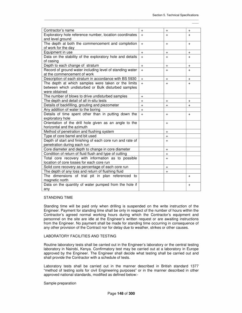
Section 5. Technical Specifications _____________________________________________________________________________________________
____
Page 148 of 300
Contractor’s name + + + Exploratory hole reference number, location coordinates and level ground
+ + +
The depth at both the commencement and completion of work for the day
+ + +
Equipment in use + + + Data on the stability of the exploratory hole and details of casing
+ + +
Depth to each change of stratum + + + Record of ground water including level of standing water at the commencement of work
+ + +
Description of each stratum in accordance with BS 5930 + + + The depth at which samples were taken or the limits between which undisturbed or Bulk disturbed samples were obtained
+ + +
The number of blows to drive undisturbed samples + The depth and detail of all in-situ tests + + + Details of backfilling, grouting and piezometer + + + Any addition of water to the boring + Details of time spent other than in putting down the exploratory hole
+ + +
Orientation of the drill hole given as an angle to the horizontal and the azimuth
+
Method of penetration and flushing system + Type of core barrel and bit used + Depth of start and finishing of each core run and rate of penetration during each run
+
Core diameter and depth to change in core diameter + Condition of return of fluid flush and type of cutting + Total core recovery with information as to possible location of core losses for each core run
+
Solid core recovery as percentage of each core run + The depth of any loss and return of flushing fluid + The dimensions of trial pit in plan referenced to magnetic north
+
Data on the quantity of water pumped from the hole if any
+
STANDING TIME Standing time will be paid only when drilling is suspended on the write instruction of the Engineer. Payment for standing time shall be only in respect of the number of hours within the Contractor’s agreed normal working hours during which the Contractor’s equipment and personnel on the site are idle at the Engineer’s written request or are awaiting instructions from the Engineer. No payment shall be made for standing time occurring in consequence of any other provision of the Contract nor for delay due to weather, strikes or other causes. LABORATORY FACILITIES AND TESTING Routine laboratory tests shall be carried out in the Engineer’s laboratory or the central testing laboratory in Nairobi, Kenya. Confirmatory test may be carried out at a laboratory in Europe approved by the Engineer. The Engineer shall decide what testing shall be carried out and shall provide the Contractor with a schedule of tests. Laboratory tests shall be carried out in the manner described in British standard 1377 “method of testing soils for civil Engineering purposes” or in the manner described in other approved national standards, modified as defined below:- Sample preparation

Section 5. Technical Specifications _____________________________________________________________________________________________
____
Page 149 of 300
BS 1377 states that initial sample preparation should include air or oven drying. As this can affect the structure of the soil this shall not be done, but the soil shall be used from its natural state, wetting or drying as appropriate to achieve the required moisture content for the test. Atterberg limit determination For liquid limit determination the sample shall be mixed for 5 minutes after adding the distilled water. The type of testing machine used shall be stated on the results sheet. Compaction test (proctor) A fresh specimen for the bulk sample shall be used for the determination of each point on the curve. This will require about 50kg of material is available for one specimen per point. Field moisture content may be wetter or drier than proctor optimum. If wetter, the sample shall be allowed to dry naturally in air to obtain points on the dry side of optimum. If the natural moisture content is drier than optimum th sample shall not be allowed to dry out but progressive amount of water shall be added to each specimen to achieve the desired content. The specimen shall be mixed for a fixed time, depending on the characteristics of the material. It is important to show a well defined peak. In no case shall less than 5 points be used. EXPLORATORY BOREHOLES Boring in Overburden Boring in over burden shall be by cable percussion, hollow stem auger or rotary drilling techniques as necessary to comply with the following requirements. The method of boring shall be such as to allow a continuous record of the strata to be obtained and shall be approved by the Engineer. Borehole in overburden shall be of sufficient size to permit the taking of 75mm diameter undisturbed samples using a thin wall tube sampler or similar approved sampler, standard penetration tests and 130mm diameter core from rock beneath overburden. The method of boring shall permit the taking the taking of undisturbed samples with their original moisture contents unaltered and shall prevent “boiling “ in cohesion less strata below the water table. Where hard strata or obstruction are encountered during soft ground boring which cannot be broken out, the Contractor shall consult the Engineer and agree the action to be taken. The type, thickness, depths, variation in consistency and sequence of the strata penetrated shall be recorded while the work is in progress. Where the method of boring permits, the depth at which water inflows are met shall be recorded and the rise in water level over a period of 20 minute shall be recorded at 5 minutes interval prior to continuing boring. The water level in the borehole shall be measured before the commencement and at the end of each day’s work. A tabulated summery of the daily water level giving the time and the depth to which the borehole was cased at each observation together with any relevant comments on boring methods which may have a bearing on the water levels, shall be given in the bore hole logs. Where a drilling fluid is required water shall be used. Boring in bedrock by rotary drilling
Section 5. Technical Specifications _____________________________________________________________________________________________
____
Page 150 of 300
Boring in rock shall be carried out by rotary drilling for extraction of continuous core of rock strata. Rock cores shall not be less than 110mm diameter or as otherwise instructed by the Engineer. Boreholes in rock shall be cased where necessary to prevent the side caving in. in the event of persistence caving, the Engineer will consider a reduction in core size in consultation with the Contractor, providing the rock core remain not less than 76mm diameter. Should any boring prove abortive because of the Contractor’s failure to begin operation with a sufficient large diameter boring, then the Contractor shall be liable for any necessary re-exploration at his own expenses. Where rock disintegrates under the action of coring the rock particles shall be recovered from the return drilling water by settlement of such particle. The nature of the rock shall be identified as far as possible and the sediment particle retained in sampling jars and clearly labeled. Drilling shall normally be carried out with double or triple tube core barrel of such manner as to ensure that the maximum of core is recovered. A close surveillance of wash water drilling pressure length of runs and all other data significant to the nature of the material drilled shall be recorded. The core barrel shall be withdrawn and core removed as often as necessary to secure the maximum possible core recovery. Coring runs shall be limited to maximum length of 3m when less than 90% of the core is recovered from a run the length of the following run shall be reduced to 1m unless otherwise directed by the Engineer. Where low percentage recover persist the Engineer in consultation with the contractor may direct the coring to be carried out using a core barrel and size appropriate for the type and condition of the bedrock. Where the condition of the rock permits, core recovery less than 80% in any drill run will not be acceptable for payment unless the Engineer is satisfied that more than 80% recovery is impracticable under the prevailing conditions. The core shall be removed from the hole immediately if blocking of the bit or grinding of the core is indicated regardless of the length of run which has been made. The Contractor shall be in general use no drilling lubricant in the borehole other than normal drilling water or air. All water used shall be clean and free of any suspended matter. The use of drilling fluids other than water or air shall be to the approval of the engineer. Handling and storage of rock cores Core barrel shall be held horizontally whilst cores are extracted, which shall normally be by applying a constant pressure without vibration and in a manner to prevent disturbance of the core. The core shall be secured in the correct order in stout wooden boxes with lids and suitable partitions. Each run shall be clearly and securely labeled to show the borehole reference number and the depth from which it was obtained. After being logged, representative solid length of core shall be wrapped in aluminium foil and coated in suitable wax so as to preserve the natural moisture content of the rock. Such coated core shall be wrapped in cloth or plastic to protect the coating and than put back in the place in the appropriate core box. The length of core protected in this way shall be recorded on the borehole log and some or all may be selected by the Engineer for dispatch to the laboratory for testing. The core boxes shall be marked prominently on the top, sides and ends or as directed by the Engineer using water proof jets black paint. The markings shall include the hole number, box number, and the total number of boxes for the hole and the depth at the start and finish of core contained within the box. The same boxes shall be painted inside the lids. Termination of boreholes The termination criteria for each bore hole will be decided by the Engineer. The Contractor may be required to terminate a borehole earlier than the depth give at the commencement of
Section 5. Technical Specifications _____________________________________________________________________________________________
____
Page 151 of 300
the hole, or extend the borehole beyond that depth if, in the opinion of the Engineer, geological conditions warrant this. 506.5 Backfilling and recording standing Water Levels After completion of boring and removal of casing, boreholes shall be left open for at least 12 hours and the standing water level recorded. after recording the standing water level, the boreholes shall either be backfilled or the standpipe piezometer installed where required within 48 backfill and compact all borings in such a manner that no subsequent depression at the ground surface due to the settlement of the backfill. 507 TRIAL PITS Trial pits shall be excavated by hand or machine to depths not exceeding 5 meters. The plan area of trial pits at ground level shall not be less than 2m unless otherwise agreed by the engineer in writing. The sides of the trial pits shall be temporarily shored when necessary by timber of adequate size placed vertically and pinned by horizontal timbers to permit inspection of the pit and sides. Alternatively, an approved proprietary shoring system shall be used. The rates of excavating shall include excavating, refilling and restoring the surface of trial pits and trenches and shall also be deemed to cover for providing ladder, temporary shoring, keeping excavation free from surface water and provision of pumping equipment for control of ground water inflow. On receipt of instructions from the engineer the contractor shall remove any temporary timber shoring and refill the trial pits and trenches in layers each layer being compacted before the next layer is placed all surplus of excavated material shall be mounded over the pits 508 SAMPLE AND FIELD TESTING the preparation for and method of taking samples, together with their size, preservation and handling shall be in accordance with BS5930 or approved national standard. All samples shall be protected at all times from drying out due to exposure to the wind and direct rays of the sun 508.1 Frequency of sampling in Boreholes Unless otherwise instructed by the engineer the contractor shall take samples as follows; In boreholes at each changing soil type or change in consistency, a small disturbed sample shall be taken, immediately following this an undisturbed sample in granular soils or a field test carried out as appropriate. Further small disturbed samples shall be taken at intervals in the same stratum midway between successive undisturbed or bulk disturbed samples. The distance between undisturbed samples measured center to center shall be 1.0 meters or as directed by the engineer. Before taking an undisturbed sample, the bottom of the exploratory hole shall be carefully cleared of loose materials and where a casing is being used the sample shall be taken below the bottom of this casing. Small disturbed samples shall be not less 1.0kg they shall be placed in a rigid container. Undisturbed core samples in cohesive soils shall be taken using open drive sampling equipment. The cutting shoes shall be clean, sharp and without burred edges. The number of blows weight of drop hammer and height of drop and length driven shall be recorded when percussion when boring is used. Following a break in the work such overnight stoppage the exploratory hole shall be advanced before undisturbed sampling, for a depth to be agreed

Section 5. Technical Specifications _____________________________________________________________________________________________
____
Page 152 of 300
with the engineer at the start of the contract. The samples shall be sealed to preserve their natural moisture contents and in such a manner as to prevent the sealants from entering any natural voids which maybe present in the sample. Where an attempt to take an undisturbed sample is aborted the boring shall be cleaned out for the full length to which the sampling tube has been driven and the recovered soil save as a disturbed sample. A fresh attempt shall then be made from the level of the base of the aborted attempt. Should this second attempt prove abortive the contractor shall adopt means of sampling or testing previously agreed with the engineer. Bulk disturbed samples shall be taken in both cohesive and non cohesive cell and shall be not less than 25kg. They shall be representative of the zone from which they have been taken and the following sampling procedure shall be used; within the limits of the zone being sampled all the recovered soil shall be placed on a suitable tray, care being taken to retain the fines of water bearing granular soils. These soils shall be mixed by shovel and quarter until the required amount of soil is obtained. The depths from which all samples are taken shall be recorded. For ‘undisturbed’ samples the level of the top and bottom of the sample, and the sample obtained shall be given, and for bulk disturbed samples the limits of the sampled zone shall be recorded. The Contractor shall be responsible for the packing of all samples and their transport to the sample store to the nominated laboratory. All samples may be discarded only on the instructions of the Engineer. The Engineer may request that certain of the samples be retained either by the Contractor or sent elsewhere. 508.2 Samples in Trial Pits Representatives samples, not less than 1kg in weight, shall be taken from each separately distinguishable stratum and at one meter intervals in strata which are over 2m thick, or as directed by the Engineer and shall be placed in airtight bottles or other approved containers. Representative bulk samples, not less than 25kg in weight shall be excavated from any part of the trial pits where directed by the engineer and shall be placed in heavy duty polythene bags or other approved containers. Bulk samples shall be labeled inside and out with waterproof labels indicating the job name, trial pit or borehole number and the depth from which the sample was taken. 508.3 Standard Penetration Tests Standard penetration tests shall carry out in accordance with test 19, Bs 1377 except as modified herein. Standard penetration tests shall be taken at 1.0 metre intervals in cohesion less soils and at each change in cohesion less soil type or density. Standard penetration shall also be taken on soft rock where soft ground boring techniques are being used and where the rock is too hard to be sampled by thin walled tube sampler (Shelby or equivalent). Standard penetration tests shall also be taken in between core runs when rotary coring in weathered rocks. Where directed by the engineer, standard penetration tests shall also be carried out in cohesive soils. The number of blows for the initial penetration of 150mm and the number of blows for each successive 75mm penetration shall be recorded for the total penetration of 450mm as follows:
Penetration (mm) 150 75 75 75 75
When the strata encountered is very dense and the number of blows exceeds, or is likely to exceed, 100 blows the penetration achieved by sets of 20 blows may be substituted for part of, or the whole of, the above.

Section 5. Technical Specifications _____________________________________________________________________________________________
____
Page 153 of 300
the driving shoe of the split spoon sampler shall be replaced by solid 60 cone of the same effective diameter for carrying out tests in sandy gravel, gravel and cobbles. These tests shall include for the taking of bulk disturbed sample over the test interval. Boring and cleaning operations in cohesion less strata shall be carried out under an induces water level above the groundwater table to prevent ‘boiling’ of the cleaned hole prior to taking standard penetration tests. GROUNDWATER AND PIEZOMETERS Groundwater Recording Groundwater when encountered in exploratory holes shall be measured and recorded in the following manner: when water is first encountered the contractor shall record the depth from the ground level to the point of entry and exploratory hole operations suspended for 20minutes during which period of depth from ground level to water level shall be recorded at 5min intervals. If at the end of the period of 20min the water level is still rising, unless otherwise instructed by the engineer, this shall be recorded with the depth of water below ground level and exploratory hole shall then be continued. If casing is used and this forms a seal against the entry of ground water, the contactor shall record the depth at which no further entry or only insignificant infiltration of water occurred. Where applicable, every effort shall be made to seal off each water strike. Water levels shall be recorded as above when further water is encountered such as when lower water tables are found after upper ones have been sealed off by the casing. Each drilling crew shall be equipped with a diameter of the specified type and shall record the water levels in each borehole at the beginning and end of each shift. On each occasion when ground water level is recorded the depth of the exploratory hole, the length of each size of any casing present and the time shall also be recorded. The Engineer may require exploratory to be left open for 24hrs after completion and water level and depth of the exploratory hole recorded at the end of this time. Samples of ground water shall be taken from each borehole or trail pit where ground water is encountered. When more than groundwater table is found each shall be sampled separately. The borehole shall be bailed out before until only uncontaminated groundwater is present in the borehole. The sample shall not be less than 0.5.1. Piezometer for recording ground water and changes in ground water levels shall be installed in exploratory holes as instructed by the engineer. They shall be described in clause 510. The contractor shall take readings of water levels I piezometers with approved equipment for the duration of the works, as instructed by the engineer. The diameters supplied shall be ELE ITM EL67-129 or similar and shall consist of an electrode and coaxial cable mounted an a winding reel which contains an electrically operated relay and vibrator and 9 volt battery. The cable shall be 100m minimum length and be graduated at 1m intervals or less. 509.2 Field Permeability Tests Where directed by the Engineer permeability tests shall be carried out in the boreholes during boring and coring operations by the following methods: Lugeon (Packer) Test method

Section 5. Technical Specifications _____________________________________________________________________________________________
____
Page 154 of 300
Where the test length is at the base of the borehole shall be flushed out with clean water before commencing the test, Tests will be carried out using drilling proceeds or in pairs of packers to test sections above the base of the borehole. Only clean water shall be injected. The contractor shall provide various mechanical and pneumatic packers so that a type appropriate to the rock conditions at the test section may be selected. The Length of a pneumatic packer shall not be less than 1m. Each Lugeon test shall be carried over a 3m-5m test length. Each test shall be carried out in five pressure stages. Test pressures will vary with depth and maybe be subject to modification by the engineer during the course of the work. In general the pressures used will be given as below: Depths 0-5m below GL:0.5, 1.0, 1.5, 1.0, 0.5 bars Depths 5-15m below GL:1.0, 1.5, 2.5, 1.5, 1.0 bars Depths 15-30m below GL: 2.0, 3.5, 5.0, 3.5, 2.0 bars Depths 30-45m below GL: 3.0, 5.0, 7.5, 5.0, 3.0 bars Depths ≥ Below GL: 4.0, 7.5, 10.0, 7.5, 4.0 bars Or as instructed on site Notes: Depths are measured to the top of the stage to be tested. Test pressure = (gauge+static) pressure where static pressure head= depth of ground water level below the gauge. the absorption at each of the five specified test pressures shall be recorded over a minimum of two 5 minutes periods or until sensibly constant results are obtained. The equipment shall be such that the pressure can be maintained with reasonable accuracy and the pressure and absorption measured. The water pump shall be centrifugal or screw action type (not piston type) and be capable of delivering 100 1/min at steady pressure of 10 bars. The equipments shall include a by-pass assembly to give full control of the quantity and pressure being applied to the test section. This shall comprise valves on both the bypass pipe and on the test supply beyond the by-pass but before the test pressure gauge and flow meter. The external diameters and the arrangement of pipes down the borehole shall be such as to allow the free passage of a diameter probe or other means of determining the water level in the hole above the packers. The following information is to be submitted to the engineer within 48 hrs of the completion of each test: Location and reference number of borehole. Single/double packer test. Depth of borehole. Depth of casing. Depth of Water table, both before test and after test. Depth of upper packer. Length of test section. Diameter of borehole in test section. Length of packers Inflation pressure of packers A minimum of two readings of the steady flow rate taken at 5 minutes intervals per test. Check diameter readings in borehole made to prove the seal of the packers during the test. Plot of applied pressure, corrected for pipe friction losses, against flow rate (abscissa). Constant Head Method

Section 5. Technical Specifications _____________________________________________________________________________________________
____
Page 155 of 300
The test shall be conducted in accordance with the principles outlined in BS 5930 When the test is to be undertaken in a borehole, the borehole shall be cleaned out at the prescribed depth under an induced head. Where necessary, a suitable gravel pack shall be used to ensure borehole stability. The use of gravel pack shall necessitate the installation of a suitable perforated feeder and observation tubes. The depth from the induced water levels to the bottom of the test section shall be greater than 5 times the diameter of the borehole. The induced water level in the borehole or standpipe piezometer shall be maintained at a prescribed level by adding water until steady conditions have been established or for a minimum of 60minutes. The total quantity of water so added shall be recorded in litres at 5min intervals. The test shall be reported using a form such as that given in Figure 24, BS 5930 Variable Head Method The test shall be conducted in accordance with the principles outlined in BS 5930. When the test is to be undertaken in a borehole, the borehole shall be cleaned out at the prescribed depth under an induced head. Where necessary, a suitable gravel pack shall be used to ensure borehole stability. The length of the test section should be at least 5times the borehole diameter. The water level in the borehole or piezometer shall be raised by adding water, or lowered by bailing out, to a level agreed by the Engineer. The water level shall be recorded as it recovers towards its equilibrium level. Monitoring should normally be at half minute intervals during the early stages of the stages. This time shall be agreed with the Engineer prior to the test in order that a representative record of the fall or rise in the water level with time can be obtained. Monitoring shall continue until the head of water above or below the ground level is not more than 1/5th of the head of water at the beginning of the test. The test shall be reported using a form such as that given in figure 23, BS 5930. INSTALLATION OF STANDPIPE PIEZOMETERS The final details of the piezometer installation will be decided by the engineer and will be dependent upon the actual subsoil and groundwater conditions found. The installation shall be generally as described below. The piezometer tip shall consist of a porous ceramic element or other suitable element not less than 150mm long with a diameter not less than 40mm and shall be protected at each end by unplasticised polyvinylchloride (uPVC) fittings. The ceramic shall have a pore diameter of the order of 69 microns and permeability of the order of 3*10 cm/sec. The uPVC tubing shall be according to BS 3506 class 6 nominal size ¾ inch and shall be supplied and installed in not less than 3m lengths excepting for one shorter length as required to suit the total standpipe dimensions. The tubes shall be jointed together and to the porous element with approved couplings and glued in such a manner that the joints remain leak proof under the anticipated head of water. Where the depth of the completed boring is greater than the depth at which the porous element and sand filter are to be installed then the bottom of the boring shall be grouted. A suitable grout consisting of cement and clay bentonite shall be prepared by thorough mixing with approved equipment with sufficient water to form a pumpable mix. The exact proportions of this backfill material shall be determined from tests carried out by the Contractor on site under the direction of the engineer’s representative to achieve a material compatible with the surrounding foundation material. Where the boring is dry, sufficient grout shall be placed in the hole using a tremie reaching to the bottom of the hole, such that the top of the grout will just reach its interface with the sand filter. Where there is water in the boring the top of the grout shall finish 1m below the proposed grout/filter interface. A similarly proportioned mixture of cement/bentonite shall then be prepared by having just sufficient water to form a cohesive paste. This mix shall be formed

Section 5. Technical Specifications _____________________________________________________________________________________________
____
Page 156 of 300
into balls of approximately 100mm diameter and placed in porous canvas bags or other porous suitable bags. The top of this plug shall be at the interface with the sand filter. Should water in the boring have been contaminated by grout it shall be replaced by clean water, the method being to the approval of the Engineer. The sand filter surround to the porous element shall be clean sand falling wholly between the limits of grading 1200 and 210 microns or other grading determined by the engineer and the volume of the sand filter to be placed shall be recorded. That portion of the sand filter below the porous element shall be placed first and all the contractors arrangements shall ensure that no sand adheres to the soil in the sides of an unlined boring. Where there is water in a boring the contractor shall allow sufficient time for all the sand to settle and measurements of the upper surface of the sand shall be taken from time to time to ensure this. The elevation of the top of this sand shall be recorded. The porous element shall be placed in the hole and with the vertical axis of the porous element co-incident with the vertical axis of the boring. The remaining sand filter shall then be added as described above. Further 100mm diameter grout balls shall be placed on top of this sand filter as described above to form a plug not less than 0.5mm thick. The remainder of the boring shall be filled with grout to ground level according to the procedure described above. Arrangements to protect the top of the uPVC tubing, using either a steel water pipe of 75mm diameter or 150mm stop cock cover both of which shall be set in grade 15 concrete to the approval with lockable cap. The ground water level shall be recorded immediately before and after installation of the piezometer. The contractor shall provide 3 wooden posts and 3 strands of barbed wire fencing as protection to the piezometer where directed by and to the satisfaction of the Engineer. A plastic or similar tag bearing the appropriate indelible identification markings shall be securely fixed to the top of the piezometer installation. STORAGE OF SAMPLES The contractor shall maintain for the duration of the site work, a temporary, secure and weatherproof store for all samples of soil and rock. The sample store shall be maintained in a tidy fashion such that samples are identifiable and accessible for inspection. Where instructed by the Engineer all core boxes shall be painted or sprayed wit effective insecticides against attack by the Engineer samples not required for testing shall be extruded and logged and the preliminary logs edited. All samples shall be kept for a period of not less the one month after submission of the approved report and shall be discarded after that time only on the instructions of the engineer. FINAL REPORT Within 14 days of the date of completion of all testing relating to a hole or series of holes the contractor shall submit to the engineer 4 No. bound copied of a final report. The report shall include full details of all drilling, pitting and testing carried out including details of any problems encountered, all borehole logs, a schedule of all insitu testing carried out with the results of these tests, a schedule of all laboratory testing carried out with the results of these tests and a complete set of color photographs of all rock cores.

Section 5. Technical Specifications _____________________________________________________________________________________________
____
Page 157 of 300
SECTION 6- FOUNDATION TREATMENT INDEX SCOPE EQUIPMENT packers water pump water pressure gauge water meter grout mixer grout pump grout pressure recorder jet grouting equipment MATERIAL DRILLING Preliminary grout holes Other injection grout hole Control holes Instrumentation holes Drainage holes Jet grouting pre-drilling WATER PRESSURE TESTING JET GROUTING definition Objective Scope of work Trial panel Pre- drilling Materials Control test INJECTION GROUT GROUTING PROCEDURE general Curtain grouting Grout pressure Record Drilling and grout crews DRAINAGE WELLS general Well drilling Well construction Case and Screen Material Filter material Development Completion of foundation Abandonment of wells Pumping and recovery tests Sampling, analysis and reporting Drilling crews

Section 5. Technical Specifications _____________________________________________________________________________________________
____
Page 158 of 300
SECTION 6 – FOUNDATION TREATMENT SCOPE This Section covers the requirements for all drilling and grouting operations carried out from both the surface and from underground excavations except site investigation holes which are considered in Section 5 and grouting within the tunnels which are covered in Section 4. The main works include, but are not limited to, the following: Drilling preliminary grout holes Drilling and re-drilling of grout holes Drilling control holes Drilling of foundation drainage wells Drilling of wells from drainage galleries Drilling of holes for instrumentation Water pressure tests Jet grouting in the dam foundations Injection grouting in the dam foundations EQUIPMENT Drilling Rigs For drilling preliminary grout holes and control holes the Contractor shall provide a rotary drilling rig and all other tools and equipment necessary for drilling in any material to obtain cores of up to 110mm diameter. The rig and equipment shall be capable of drilling inclined and vertical holes of length up to 100m. For injection grouting the Contractor shall provide percussive or rotary drilling rigs that are capable of drilling vertical or inclined holes in the diameters specified in Clause 604.

Section 5. Technical Specifications _____________________________________________________________________________________________
____
Page 159 of 300
For installation of instrumentation and predrilling of the jet grout holes rotary drilling rigs are required that are capable of drilling holes 150mm diameter up to 60m deep. For foundation drainage wells, rotary or cable tool rigs are required that are capable of drilling holes at 250mm diameter to a maximum depth of 60m. For the wells from the drainage galleries, the Contractor shall provide rotary or cable tool rigs that are capable of drilling holes at 250mm diameter as follows: Up-holes to maximum length of 50m, which may be drilled from the ground surface subject to the approval of the Engineer. Down-holes to a maximum depth of 20m to be drilled from within the gallery. Inclined holes to a maximum length of 20m to be drilled from within the gallery. Packers The Contractor shall provide on site sufficient quantity of mechanical and pneumatic packers which can be easily expanded to seal a drilled hole of any diameter being used. Water Pumps Pumps for water pressure tests shall be capable of delivering 120 1/min. of water at a steady pressure of 10 bars. Water Pressure Gauges Pressure gauges indicating pressures up to 10 bars shall be provided for use in in water tests. Gauges shall be graduated to 0.1 bar, and shall be fitted with friction needles to record the maximum pressure used. Water Meters Water meters shall be capable of withstanding pressures up to 10 bars and metering flows of up to 120 1/min. The Contractor shall test the accuracy of all water meters periodically and make any corrections that are necessary to maintain the error to within 2% of the reading value. Grout Mixer Grout mixers shall be high speed mixers, which operate at 1500 rpm or faster, capable of preparing a colloidal grout. The grout mixers shall have a minimum capacity of 250 1. Grout shall be stored before injection in an agitator which shall have a capacity of not less than 500 1. Grout Pumps Grout pumps shall be capable of delivering thick grout (water: cement 0.6:1 by volume) at a rate of 60 1/min at a steady pressure of up to 20 bars. A recirculation grout system shall be used with grout flow and pressure measured and controlled at the top of the hole. Grout Pressure Recorders Pressure recorders capable of measuring and recording grout pressures of up to 20 bars shall be provided. The recorders shall be accurate to within 3%. Jet Grouting Equipment Details of the specialist drilling, mixing and pumping equipment required for the construction of the jet grout curtain shall be submitted to the Engineer 84 days in advance of construction of the trial panel.

Section 5. Technical Specifications _____________________________________________________________________________________________
____
Page 160 of 300
MATERIALS Grout shall be composed of a mixture of cement and water, with the possible addition of sand, bentonite and other admixtures. The grout mixture shall be determined by the Engineer’s Representative to meet the ground conditions encountered at each stage. Cement, water and sand shall comply with the requirements of Section 3. Bentonite shall be supplied in powder form and shall have a liquid limit of not less than 400%. DRILLING 604.1 Preliminary Grout Holes The drilling of preliminary grout holes shall be carried out by rotary diamond drilling for the extraction of continuous cores in accordance with the procedures given in Section 5. Other Injection Grout Holes Injection grout holes shall be drilled either by rotary or percussive drilling equipment as instructed by the Engineer. Rigs shall be capable of drilling both vertical and inclined holes. The following diameters and depths will be required Min. Diameter (mm) Max. Depth (m) Rotary drilling/Percussive drilling 45 100 Contract/consolidation grouting 38 10 grout curtain 60 75 No core recovery will be required from rotary drilling. The holes shall not deviate from the proposed alignment by more than 1%. The deviation of the hole shall be monitored by the Contractor using a method approved by the Engineer. Control Holes Control holes shall be inclined holes drilled by rotary drilling rigs with core recovery to a maximum drilled length of 100m to provide cores of diameter not less than 110m. Steel casing shall be used where necessary. Instrumentation Holes Holes for instrumentation shall be vertical holes drilled by rotary drilling rigs with no core recovery. The minimum diameter shall be 150mm and the maximum depth of 60m. Steel shall be used where necessary. Jet Grouting Pre-drilling Pre-drilling for jet grouting is specified in Clause 606.5. WATER PRESSURE TESTING Water pressure tests (lugeon tests) shall be carried out in preliminary, secondary, tertiary and subsequent ground holes and control holes as directed by the Engineer to determine the permeability of the ground. The test pressures shall be as follows, subject to modification by the Engineer’s Representative. During the course of the work:-

Section 5. Technical Specifications _____________________________________________________________________________________________
____
Page 161 of 300
Preliminary and control Holes Stage 0-5m below GL: 0.5, 1.0, 1.5, 1.0, 0.5 bars Stage 5-15m below GL: 1.0, 1.5, 2.5, 1.5, 1.0, bars Stage 15-30m below GL: 2.0, 3.5, 5.0, 3.5, 2.0 bars Stage 30-45m below GL: 3.0, 5.0, 7.5, 5.0, 3.0 bars Stage _> 45m below GL: 4.0, 7.5, 10.0, 7.5, 4.0 bars Secondary, Tertiary and Subsequent Grout Holes Stage 0-15m below GL: 1.0, 1.5, 1.0, bars Stage 15-30m below GL: 1.5, 2.5, 1.5, bars Stage 30-45m below GL: 4.0, 7.5, 4.0 bars Stage _ >45m below GL: 5.0, 10.0, 5.0, bars Water tests shall be carried out over stages of 5m or as determined by the Engineer’s Representative. The absorption at the specified test pressures shall be recorded over 5 minute periods until sensibly constant results are obtained. The equipment shall such that the pressure can be maintained with reasonable accuracy and the pressure and absorption measured. Permeability shall be expressed in terms of “Lugeons”. An absorption of I litre per minute per meter length hole at a pressure of 10 bars represents a permeability of 1 Lugeon. JET GROUTING Definition Jet grouting uses high pressure water and compressed air jets to break down the soil structure, remove the soil particles, and replace them with cement based grouts, simultaneously injected under pressure. Objectives The objective of the jet rounding is to form a row of water tight interlocking column of grouts within the grade (IV) to (VI) material of the core foundation. Construction of the jet grout curtain shall precede that of the injection of the grout curtain. Scope of work The jet grouting shall be carried out by a specialist sub-contractor subject to the approval of the Engineer. The Contractor shall submit in writing details of the sub-contractor and of the equipment and method he proposes to use in 84 days in advance of the construction of the trial panel. The scope of work comprises an impermeable jet grout curtain, of maximum depth of 35m and area approximately of 16000m2. a trial panel and the removal of spoil to the area shown on the drawings. The contractor shall ensure that any spillage of bentonite, from the drilling fluids or backfill material, are cleared up immediately and do not contaminate the permanent works. Trial panel Before commencing the jet grouting to be incorporated into the permanent works the Contractor Shall construct a trial panel in the position shown on the drawing or other location approved by the Engineer.

Section 5. Technical Specifications _____________________________________________________________________________________________
____
Page 162 of 300
The Contractor shall use the equipment, materials and technique that he proposes for the permanent works. On completion of the panel a section of the adjacent ground shall be excavated to a maximum depth of 5m to enable a visual inspection of the panel to be made. The dimensions of the panel shall be 12m long by at least 20m deep. In collaboration with the Engineer the Contractor shall determine the optimum column diameter, jet pressure, speed of withdrawal and rotation and grout mix. At least 28 days before commencing the trial panel the Contractor Shall submit details of his proposal for the trial panel for the approval of the Engineer. On completion of the trial the Contractor shall submit a report on the trial to the Engineer. Pre-drilling At each grouting position a borehole of minimum diameter of 150mm shall be drilled to 500mm below the lower limit of the jet grout curtain. Pre- drilled holes shall be stabilized by means of bentonites slurry and shall not deviate from the vertical by more than 1%. The verticality of the hole shall be monitored by the Contractor using a method approved by the Engineer. Jet grouting equipment shall be capable of providing separate soil-eroding and grout-placement jets, consistent with achieving a high degree of removal and replacement by grout, of the ground to be treated. The equipment shall incorporate a mechanism, normally a compressed air element, in the erosive jet, to assist in the transportation of excavated spoil to the surface in volumes consistent with the speed of grouting and prevention of the surface heave. Jet grouting equipment introduced to the borehole shall not exceed 90mm external diameter. Jet grouting shall commence from the base of the zone to be treated and, unless unavoidable, shall be carried out continuously at each position, working upwards until the top of the treatment zone is reached. In the event that treatment is unavoidably interrupted, for any reason, the Contractor shall ensure that the work is re-commenced at a depth at least 500mm below that at which it was interrupted, including re-drilling if necessary. From the results of the trial panel, and in collaboration with the Engineer, the Contractor shall select appropriate working parameters, with reference to the prevailing soil conditions and the size of the individual grouted element to be constructed. Working parameters will normally fall within the following ranges:- Erosive jet (water) :- pressure 200 to 500 bars :-flow 40 to 100 1/min Erosive jet (air) :- pressure 7 to 10 bars :-flow 1500 to 2500 1/min Grout jet :- pressure 8 to 40 bars :- flow 50 to 250 1/min Grout stem lifting speed:- 20 to 1000 1/min Grout stem rotation :- 2 to 50 rpm Operating speeds and fluid pressures shall be monitored adjacent to each working position and flows shall be monitored at the mixing/ pumping station, using agreed procedure on a regular or continuous basis. On completion of grouting at each position, the Contractor shall take all necessary measures to ensure that the finished level of grouting is maintained during the initial bleed and set period. 606.7 Materials

Section 5. Technical Specifications _____________________________________________________________________________________________
____
Page 163 of 300
The contractor shall be responsible for the design of the jet grout. The mix will consist of ordinary or sulphate resisting Portland cement and water with bentonite in proportion and at a water to solid ratio to be proposed by the Contractor and agreed by the Engineer. In particular cases proprietary additive may be used for a specific purpose. Sand will be excessively abrasive under pressure and shall not be used as filler. The permeability co-efficient of the grout shall be not more than 10 m/sec at 56 days age when tested under an hydraulic gradient of 150. The tests shall be continued for sufficient time to ensure that no significant increase in permeability occurs with time and in any case not less than 10 days. The water quality, in particular the pH shall be similar to that existing at the site. The stress/ strain relationship as determined by means of drained triaxial tests on 100mm diameter specimens shall comply with the following:
Item Range kn/m2 Deviator stress at 5% axial strain 700- 1100 Tangent modulus (Et) at 1% axial strain 40000-70000
Test shall be carried out at confining pressures of 400 and 800 kn/m2 on specimens at 56 days age. Control tests The contractor shall be responsible for routine control testing of the jet grout mix. The testing procedure shall be agreed with the Engineer and shall include the determination of the following: Density Viscosity Crushing strength The normal strength control test shall be a crushing test on 100mm cube or cylinder samples carried out at 28 days age, and also if practicable at 7 days or such other intermediate age as may be agreed. The required minimum crushing strength shall be determined and agreed during the course of development of the mix. Suitable samples of material shall be taken for laboratory testing including triaxial shear tests and permeability testing. INJECTION GROUT MIX Grout will generally be composed of a stable cement grout. Grouting mortar (cement, sand, and water mixture) will only be used in the case of high absorption. Bentonite may be added if required to obtain a stable mix as defined below. In all case, the Contractor shall submit for approval by the Engineer the composition and method of preparing the grout which he proposes to use. Prior to their use, these grouts must undergo laboratory tests allowing the preparation of the diagram showing: The equiviscocity curves The limit settling curves The curve of maximum possible viscosity for injecting. These tests are to be carried out on grouts prepared in the grout batching station or at least by methods similar to those used for the grout to be applied.

Section 5. Technical Specifications _____________________________________________________________________________________________
____
Page 164 of 300
Grout mixes to be injected shall not have a settlement level exceeding 5% as determined in accordance with ASTM 232. This settling shall be expressed by the ratio between the volume of water visible above the grout after setting and the total volume. The viscosity shall be measured by means of a marsh cone The grout must be a mixture of Portland cement, and water or cement, sand and water mixture. The proportions will vary depending on the hole characteristics revealed by the drilling and the injection operations. Generally speaking, sand shall not be used and the water-cement ratio shall vary from 3:1 to 0.75:1 by volume. The injection pressures will depend on the condition encountered on the site during injection. The probable pressures used for each type of injection are described later in the relevant sections. GROUTING PROCEDURE General The following general requirement shall be observed:- Grouting holes shall be properly flushed to the bottom of the hole with clean water before commencing injection. Flushed shall continue until clean water emerges at the top of the hole. In general no holes shall be left open whilst other holes in the vicinity are being grouted. The number of holes to be drilled at anytime shall therefore be limited to the number which can be grouted simultaneously. Grouting shall be generally carried out by the method of descending stage and packer in stages of 5 to 10m. Upon completion of a stage the hole shall be capped until the grout has taken its initial set. If a further stage is to be grouted the hole shall then be flushed out unless the Engineer orders that it shall be re-drilled. No payment will be made for Drilling necessitated by delays in flushing out attributable to the Contractor. Care shall be taken to avoid uplifting structure or opening fissures during grouting by the use of excessive grouting pressures. Suitable control measures shall be taken to detect uplifting. If grout appears at ground level during the injection operation grouting shall be suspended in the location until the grout has had time to set Curtain grouting Curtain grouting shall be carried out in accordance with the following procedure subject to modification as determined by the Engineer during the Course of the work:- 1. Preliminary holes shall be drilled at 24m centers along the line of the curtain to the depths shown on the drawings and water tested in descending stages of 5m. The extent of curtain grouting will be based on the water test results of the preliminary holes 2. Primary holes shall be drilled at 6m center and grouted in descending stages of 5m. The first stage of primary and all subsequent holes shall be grouted with the packer sealed 5m above the base of the jet grouted curtain. 3. Intermediate (secondary) holes shall be drilled, water tested and grouted in descending stages of 5m. In areas where the permeability is less than 5 lugeon s no further grouting need be undertaken. 4. In areas where the permeability is greater than 5 lugeons, intermediate (tertiary) holes shall be drilled, water tested and grouted following the same procedure. 5. The effectiveness of the treatment shall be checked by water tests in inclined control holes and further grouting carried out if necessary in accordance with the instructions of the engineer‘s representative.

Section 5. Technical Specifications _____________________________________________________________________________________________
____
Page 165 of 300
Grouting in any stage shall be continued until refusal, that is when the absorption measured over two consecutive periods of 5 minutes is reduced to 2 litres per minute per meters of stage at the pressures for the stage being grouted, or as other wise directed by the Engineer. The grouting procedure will be determined on site by the Engineer. For initial guidance the following procedure is preferred: The initial grout mix shall be 3:1 water: cement by volume. If there is no rise in pressure after the injection of 200 litres of grout over a 5m stages the mix shall be thickening to 2:1 and then if necessary to 1:1 and 0.75:1. As soon as the pressure starts to rise the mix shall be maintained constant and the grouting continued until refusal. Grouting at any stage shall continue until a volume of 200 l/m per metre of stage is achieved, the operation shall be suspended until the grout has had time to set, after which injection shall be continued in units of 200 liters per metre stage, following the procedure above, to refusal. Bleeding of the grout hole shall be undertaken at 15 minutes intervals during injection. Grout Pressures Grout pressures shall vary in accordance with the type of work, ground conditions and depth of the stage, as directed by the Engineer. The following pressures measured at the top of the hole are given for guidance:
Type of Grouting Pressure (bars) Curtain grouting P= 0.2H (min1.5) Consolidation grouting P=0.2H(min 1.5, max 10)
Where H is the depth of the hole to the top of the stage to be grouted, in metres. Records Full records shall be kept of the progress of drilling, permeability tests, grout mixes, pressures and consumption of grout materials. Daily record sheets in duplicate shall be delivered to the Engineer’s Representative the day following the completion of each day’s work. 608.5 Drilling and Grouting Crew All foremen, drillers and leading hands employed on drilling and grouting work shall have adequate previous relevant experience. Satisfactory written evidence of such experience shall be supplied to the Engineer’s representative. 609 DRAINAGE WELLS General Foundation drainage wells and wells from the drainage galleries shall be constructed in the locations shown on the drawings to control seepage and relieve uplift pressures in the foundations. Well Drilling The wells shall be drilled either by the Direct Circulation rotary method or the Percussion (Cable Tool) method.

Section 5. Technical Specifications _____________________________________________________________________________________________
____
Page 166 of 300
In the event of the Direct Circulation Rotary Method being adopted by the Contractor, the following drilling fluids will be acceptable. Water Organic Polymer and with suitable dispersants. The maximum allowable viscosity for this mud shall not exceed 60 API secs as measured by a Marsh funnel. Bentonitic Mud with suitable dispersants to break down filter cake. The maximum allowable viscosity for this mud shall not exceed 32 API secs as measured with a Marsh funnel. A mixture of bentonitic mud and organic polymer for this mud the bentonitic component shall have a viscosity not exceeding 32 API secs and the mixture shall have a viscosity not exceeding 60 API secs. 609.3 Well Construction The wells shall be constructed as shown on the Drawings and in accordance with the following general requirements. The overall diameter of each well shall be not less than 240m. The maximum depth of the foundation wells will not exceed 60m below existing ground level. The maximum length of the up holes from the drainage galleries will not exceed 50m. The maximum depth of the down holes from the drainage galleries will not exceed 20m. Following completion of drilling, the contractor shall install a 100m nominal diameter thermo-plastic casing and screen shall be as specified in clause 609.4 of this specification. The lengths of casing and screen to be installed in each well will be decided by the Engineer on receipt of all drilling and geological information from the contractor. Following the installation of the casings and screen the contractor shall place filter material in the annular space between the hole and casing/screen from the bottom of the hole to the level shown on the drawing. The method of placing shall be by means of a tremie pipe installed in the annular space between the hole and casing/screen. The nature and gradation of the filter shall be as specified in Clause 609.5 of the specification. The wells shall be developed as described in clause 609.6 of the specification. The contractor shall place additional filter material as necessary to compensate for settlement during or after development. After the completion of development the wells shall be finished as described in clause 609.7 of the specification. Casing and Screen Materials Materials The materials for the casings and screens shall be either polyvinyl chloride (PVC) or Acrylonitrile-butadiene-styrene (ABS) and shall comply in all respects with the Standard Specification for Thermoplastic Water Well Casing Pipe and Couplings made in Standard Dimension Ratios (SDR, ANSI/ASM F480-81, September 1981, or equivalent approved. Dimensions The wall thickness and tolerances for the casing pipes and screens shall comply with SDR 21 for a nominal pipe diameter of 100 mm (4 inches) as follows: Nominal Pipe Size : 100mm (4 inches) Minimal Wall Thickness : 5.4mm (0.214 inches)
Section 5. Technical Specifications _____________________________________________________________________________________________
____
Page 167 of 300
Wall Thickness Tolerance : (+0.026 inches) Out of Roundness Tolerance : +1.27mm (+0.05 inches) Lengths The well castings and screens shall be supplied in 3 m (10ft.) length Joints The joints for casing and screen shall be of the screwed type in accordance with table 3 of the ANSI/ASTM F480-81 Specification. Slot Width etc for screen All pipes to be used as screed shall be provided with perforations which shall consist of machine out slots. Slots shall have smooth sharp edges and shall be free of burrs, chipped edges or broken areas on the interior or exterior surfaces of the pipe. The slots shall be horizontal, i.e. perpendicular to the longitudinal axis of the pipe. The dimensions of the slots shall be as follows: Slot width: 1mm Length of slot: 50m Number of slots per linear meter per row (approx.): 100 Number of rows around the circumference: 3 Open area (approx.) 5% Sealing plugs Where appropriate, the bottom end of the casing/screen string shall be sealed with a screwed plug made of the same material as the casing and screen. Centralizers To ensure that the filter material forms a continuous envelope around the screens the casing/screen string shall be centralized at 5m intervals, using approved centralizers made of either ordinary flexible steel or of the same material as the screen. Filter Material The filter shall be of siliceous material consisting of naturally rounded quartz sand. Crushed rock will not be accepted. It shall be a medium to coarse grained sand with a uniformity coefficient not greater than 3 as shown on the drawings. The uniformity coefficient (UC) is defined as the quotient of the 40 per cent (retained) size of the sand divided by the 90 per cent size (retained). Development After construction the wells shall be developed to clean the well, to disperse the drilling fluid and to break down and remove material which may have clogged the slotted casing. The well shall be developed in two stages in accordance with the Engineer’s detailed instructions. The first stage shall consist of pumping into the borehole clean water with or without dispersant, as appropriate, until all drilling fluid and foreign debris have been removed. The second stage shall consist of surging the well with compressed air and carrying out air-lift pumping for a period of not less than 6 hours, or for such a period as deemed necessary by the Engineer. The eductor pipe and airline of the air-lift assembly shall have diameters not less than 50mm and 12mm respectively and the compressor shall be capable of developing a maximum pressure or 5 bars. The contractor’s attention is drawn to the necessity for extra are during development so as to avoid emptying the casing/screen column, which might lead to collapse. Completion of Foundation Wells

Section 5. Technical Specifications _____________________________________________________________________________________________
____
Page 168 of 300
The wells shall be completed as follows: Grouting and Sealing Cement/bentonite grout shall be placed between the surface of the hole and the 100mm diameter casing from ground level to a level below ground as shown on the drawings or as otherwise directed by the Engineer. The exact proportion of the back fill material shall be determined from tests carried out by the contractor on site under the direction of the Engineer’s representative to achieve a material compatible with the surrounding foundation material. These tests shall be completed before drilling commences. No pumping or any other operations will be allowed within 72 hours of the completion of grouting. Well Heads The Contractor shall provide and keep in place at each borehole at all times a suitable tight fitting temporary cover to seal off the borehole. Following completion of air-lift pumping and grouting, each well shall be capped as shown on the drawings. Abandonment of Wells Should the Contractor fail to complete any well as specified or if at any stage the satisfactory completion of any well is prevented by collapse due to caving-in or to any other cause or by other reason due to faulty workmanship or negligence on the part of the Contractor, the Engineer’s Representative will order the work to be discontinued and/or the borehole to be abandoned and the Contractor shall forthwith refill and plug the borehole at his own cost and to the satisfaction of the Engineer. Such abandoned well shall not be paid for. The Contractor may where possible recover or salvage materials from a well so abandoned but such materials shall be used elsewhere on the Contract only if permission to do so is given by the Engineer. Pumping and Recovery Tests Following the completion of construction of all wells, the Contractor shall carry out pumping and recovery tests on a selected number of wells as directed by the Engineer. The total number of wells to be tested is not expected under the Contract. Pump Testing Pump testing shall be carried out for a period of approximately 24 hours by means of an air-lift pump or a suitable shaft driven, submersible, or other pump. The diameter of the pump shall be such as to allow for water level measurement in the pumped well. The pump shall be capable of a discharge between 5 and 60 litres/minute from a level of approximately 6 meters below ground level. For measurements of discharge the Contractor shall employ a 908 V-notch weir suitably calibrated. Throughout the test, the discharge rate shall remain reasonably constant. During pumping the Contractor shall make arrangements for the measurement of water levels in at least six observation wells located in the vicinity of the pumped well. The Engineer will specify to the Contractor the wells to be monitored during pump testing. Water levels in the pumped and observation wells shall be measure at the following frequency using electrical water level indicators with a tape graduated to one hundredth of a metre. (ii) Recovery Test Immediately after the cessation of pumping the rising water levels shall be measured for a period of not less than 12 hours in both the pumped and observation wells and at the same frequency as during pump testing.

Section 5. Technical Specifications _____________________________________________________________________________________________
____
Page 169 of 300
609.10 Sampling, Analysis and Reporting Sampling During drilling of each borehole duplicate formation samples of not less than 1 kg each shall be collected at 1 meter depth intervals for each well. Each sample shall be placed in a suitable glass or plastic jar and shall be clearly and securely labeled with the well reference number, date, time and depth at which it was taken and shall be retained for inspection by the Engineer. One sample of each pair shall be retained for reference. (ii) Analysis The Contractor shall carry out sieve analyses on samples selected by the Engineer. The analyses shall be carried out promptly so as to enable the Engineer to design the well immediately after the completion of the borehole. Recording Full and detailed daily records of all operations and tests shall be maintained during the construction of the wells. The Contractor shall record all data and information which are required on agreed reporting forms, which shall be submitted to the Engineer in duplicable not later than 14 days after the completion of work at each well. These reports shall include: Daily Drilling Report Well Lithology Log Sand Analysis Report Well Development Report Pumping and Recovery Tests Report Drilling Crews All foremen and drillers employed on the construction of the well shall have had adequate experience on similar work elsewhere. Satisfactory written evidence of each experience shall be supplied to the Engineer’s representative

Section 5. Technical Specifications _____________________________________________________________________________________________
____
Page 170 of 300
SECTION 7- PIPES AND VALVES INDEX. PART 1 GENERAL REQUIREMENT 701 SCOPE 702 SUITABILITY 703 DIMENSIONS OF PLANT 704 DRAWINGS AND MANUFACTURE OF PLANT 705 INSPECTION AND TESTING OF PLANT 706 MANUFACTURES CERTIFICATES 707 PACKING AND PROTECTION OF PLANT FOR SHIPPING 708 MARKING OF PLANT 709 HANDLING OF PLANT 710 ACCEPTANCE OF PLANT 711 STANDARDS PART 2 STEEL PIPEWORK 731 STEEL SPECIFICATION 732 GRADE OF STEEL 733 THICKNESS OF PIPES AND FITTINGS 734 INSPECTION AND TESTING OF PIPES AND FITTINGS 735 PIPE LENGTHS 736 DIMENSIONS OF FITTINGS 737 FLAGGED JOINTS 738 FLEXIBLE JOINTS 739 MATERIALS FOR THE ASSEMBLY OF FLEXIBLE JOINTS 740 JOINT ANGULAR DEFLECTION AND PIPE TOLERANCES EPOXY RESIN COATING PART 3 - VALVES (A) GATE VALVES 751 GENERAL 752 CONSTRUCTIONS 753 TESTING (B) NOT USED (C) BUTTERFLY VALVES 757 GENERAL 758 CONSTRUCTION 759 PERFORMANCE 760 TESTING (D) TERMINAL DISCHARGE VALVE 761 GENERAL 762 CONSTRUCTION 763 PERFORMANCE 764 TESTING (E) SUBMERGED DISCHARGE VALVES 765 GENERAL 766 CONSTRUCTION 767 PERFORMANCE

Section 5. Technical Specifications _____________________________________________________________________________________________
____
Page 171 of 300
768 TESTING PART 4- PIPE WORK ERECTION 771 GENERAL 772 FLANGED JOINTS7 773 CUTTING PIPES 774 PROPRIETARY JOINTS AND COUPLINGS 775 JOINTING OF COUPLING AND FLANGED ADAPTORS 776 FIXING VALVES AND FITTINGS 777 GROUTING IN IRONWORK AND PIPE 778 PIPE SUPPORTS AND THRUST BLOCKS 779 PRESSURE TESTING OF PIPE WORK 780 CLEANSING OF PIPEWORK
Section 5. Technical Specifications _____________________________________________________________________________________________
____
Page 172 of 300
SECTION 7- PIPES AND VALVES PART 1- GENERAL REQUIREMENTS 701 SCOPE This section covers the supply and installation of steel pipe work and valves in the draw off tower and tunnel. In this section ‘plant’ refers to pipes, pipe fitting, valves and associated equipment. The general arrangements are shown on the drawings and although dimensions are indicated or inferred the Contractor may offer items of differing dimensions, other than of smaller diameter, providing the intended requirements are met. 702 SUITABILITY All plant to be supplied shall be suitable for water works purposes for the transmission of raw and portable water (treated water) in the tropical conditions prevailing in Kenya and in particular at the location of the works. A typical chemical analysis of the raw water is presented in Appendix F. 703 DIMENSIONS OF PLANT All pipes shall be supplied in accordance to suit the drawings and tolerances appropriate to the type and class of pipes specified in the relevant standard specified or other standard approved by the Engineer. All valves and fittings shall be supplied to suit the drawings and where applicable in accordance with the dimensions stated in the relevant standard for the manufacture of pipe. The Contractor may manufacture valves and fittings to other dimensions subject to the approval of the Engineer, however, the Contractor will be responsible for any redesign resulting from the use of fittings and valves to other construction dimensions. Where the pipe and fittings diameters shown on the drawings are not manufactured the nearest available diameter above the diameter required together with reducer pieces may be supplied, subject to the approval of the Engineer. 704 DRAWINGS AND MANUFACTURE OF PLANT. Drawings of all plant including flanges and couplings etc shall be submitted to the Engineer for approval. The Contractor shall not order the manufacture or fabrication of any plant until receipt by him from the Engineer of the necessary approved drawings or other approval. The Engineers approval of or comments on the drawings or proposals shall be given within 28 days of their receipt by the Engineer. 705 INSPECTION AND TESTING During manufacture and before dispatch from the placed or manufacture the Contractor shall allow for inspection of the plant by an inspector appointed by the Engineer. The inspection will include attendance at all pressure and material tests, execution of dimensional checks, inspection of the workmanship and standard of manufacture with scrutiny of evidence of the materials used in the fabrication of the plant. The Contractor shall arrange for such testing as may be required to be carried out at the place of manufacture according to this specification. If there are no facilities at the place of manufacture for making the prescribed tests the Contractor shall bear the cost of carrying out the tests elsewhere.

Section 5. Technical Specifications _____________________________________________________________________________________________
____
Page 173 of 300
The contractor shall supply furnish and prepare the necessary test pieces and samples and shall supply and provide all tests rigs, equipments appliances, labour and any other facility required for the inspection and testing of the plant. The Engineer and his inspector shall be allowed full access to all areas at the place of manufacture or else where testing, furnishing and preparation of materials for the performance and testing of work under this specification is taking place. The Contractor shall furnish the Engineer with reasonable facilities and space (without charge) for the inspection, testing and obtaining of such information as he desires with respect to the character of material in use and the progress and manner of the work. 706 MANUFACTURE’S CERTIFICATES The Contractor shall furnish the Engineer with a manufacture’s certificate in respect of every consignment of the plant confirming that all items of plant comprising the consignment comply in all respects with the requirements of the specified standard. The original and one copy of such manufactures certificate shall be delivered to the Engineer not later than seven days prior to the intended date of delivery of the plant to site. 707 PACKING AND PROTECTION OF PLANT FOR SHIPPING All items shall be adequately crated or packaged to withstand damage and deterioration due to shipping, handling and storage. Protection shall be provided to prevent damage to flanges and pipes ends to prevent ingress of foreign matter. The methods of protection and shipping shall be to the approval of the Engineer. Bolts of the same length and size (and their accompanying nuts and washers) shall be packed together in boxes not exceeding 100 kg gross weight. Joint rings and gaskets shall be packed in boxes and separate packages shall be provided for each size and description of ring and gasket. 708 MARKING OF PLANT All plant shall be marked in accordance with Clause 5 of BS 477 and Clause 37 of BS 5163. Before shipping all items shall be clearly marked. All crates or packages except for single pipes shall be marked on two sides with indelible paint with the name of the project, the client and the contract number as shown on Appendix G and shall also bear marks indicating the contents. 709 HANDLING AND PLANT The engineer will reject any pipes or fittings which have been damaged due to handling procedures, and methods of transport and shipping which do not concur with the following:- Pipes should not be stacked more than two tiers high unless otherwise approved by the Engineer. Pipes fittings and valves shall not be dropped, or allowed to land on sharp or other objects which will cause bends, dents or damage to the coating. When lifting pipes and fittings special lifting hooks with curved saddles to fit the curvatures of the pipe or fitting shall be used. Alternative types of lifting hooks, clamps or slings, may be used subject to the Engineer’s approval.
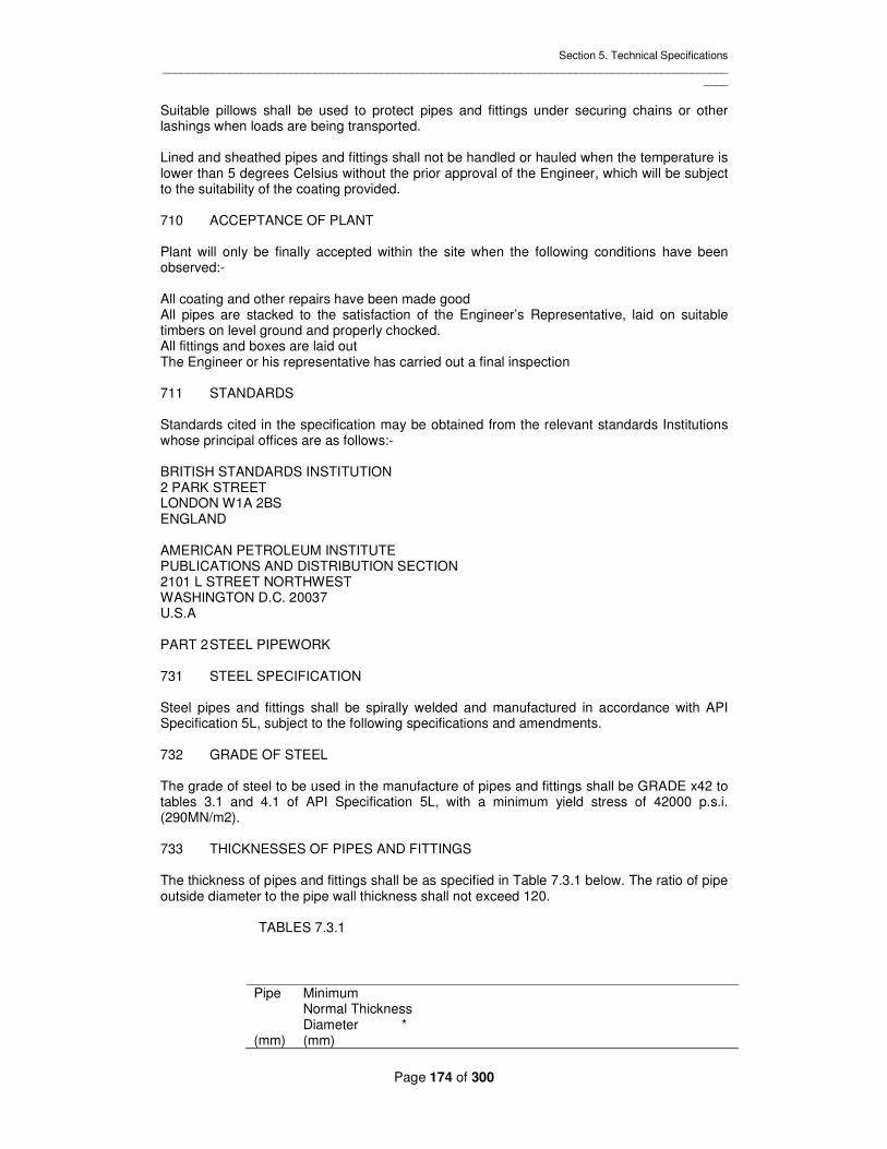
Section 5. Technical Specifications _____________________________________________________________________________________________
____
Page 174 of 300
Suitable pillows shall be used to protect pipes and fittings under securing chains or other lashings when loads are being transported. Lined and sheathed pipes and fittings shall not be handled or hauled when the temperature is lower than 5 degrees Celsius without the prior approval of the Engineer, which will be subject to the suitability of the coating provided. 710 ACCEPTANCE OF PLANT Plant will only be finally accepted within the site when the following conditions have been observed:- All coating and other repairs have been made good All pipes are stacked to the satisfaction of the Engineer’s Representative, laid on suitable timbers on level ground and properly chocked. All fittings and boxes are laid out The Engineer or his representative has carried out a final inspection 711 STANDARDS Standards cited in the specification may be obtained from the relevant standards Institutions whose principal offices are as follows:- BRITISH STANDARDS INSTITUTION 2 PARK STREET LONDON W1A 2BS ENGLAND AMERICAN PETROLEUM INSTITUTE PUBLICATIONS AND DISTRIBUTION SECTION 2101 L STREET NORTHWEST WASHINGTON D.C. 20037 U.S.A PART 2 STEEL PIPEWORK 731 STEEL SPECIFICATION Steel pipes and fittings shall be spirally welded and manufactured in accordance with API Specification 5L, subject to the following specifications and amendments. 732 GRADE OF STEEL The grade of steel to be used in the manufacture of pipes and fittings shall be GRADE x42 to tables 3.1 and 4.1 of API Specification 5L, with a minimum yield stress of 42000 p.s.i. (290MN/m2). 733 THICKNESSES OF PIPES AND FITTINGS The thickness of pipes and fittings shall be as specified in Table 7.3.1 below. The ratio of pipe outside diameter to the pipe wall thickness shall not exceed 120. TABLES 7.3.1
Pipe Minimum Normal Thickness Diameter * (mm) (mm)

Section 5. Technical Specifications _____________________________________________________________________________________________
____
Page 175 of 300
The minimum thickness for steel fittings shall take into account flexibility and stress intensification factors. The Contractor shall present full calculations based on CP 2010 for each type of fitting for approval by the Engineer prior to manufacture. 734 INSPECTION AND TESTING OF PIPES AND FITTINGS All pipes and fittings shall be hydrostatically tested to the pressures stated in API Specification 5L. Welding shall be inspected by radiography or other method to be agreed by the Engineer in the following proportions. One percent of all welds, except in the case of a new factory where five per cent shall be examined. Destruction tests shall be carried out in accordance with the requirements of section four of API 5L as appropriate. In addition to these requirements all fittings shall be further examined as follows:- 10% of all welds shall be radio-graphed and the exposed film made available for inspection by the Engineer. Where considered necessary the Engineer may require additional radiography and hydraulic tests on fittings on which doubtful weld inspection results are revealed. 735 PIPES LENGTHS Pipes shall normally be supplied in Double Random Lengths, not exceeding 12.0m, the distribution of lengths shall apply to each consignment shipped, in accordance with API Specification 5L Clause 6.5. In addition 1% of all the pipes shall be to the tolerances specified in Clause 740 over their whole length and such pipes shall be clearly marked. Straight pipes of specified lengths shall be construed as fittings. 736 DIMENSIONS OF FITTINGS The dimensions of fitting shall generally be in accordance with the following:- Bends shall be of radius equivalent to 5 diameters for large radius bends, or 11/2 diameters for short radius bends with a straight length at each end of 500mm for large radius bends, and 250 mm for short radius bends. Tees and swept tees shall be generally in accordance with Table 8 of BS 534, subject c (ii) below.
1400 12.7 1200 11.1 1000 8.7 800 7.1 200 4.0

Section 5. Technical Specifications _____________________________________________________________________________________________
____
Page 176 of 300
Other fittings shall be to the manufacture’s own dimensions subject to the following constraints:- Reducers shall have a net reduction in diameter of half the length over which reduction occurs. All fittings except long radius bends shall have a straight length of 250mm at each end. 737 FLANGED JOINTS All flanges shall be faced and drilled to conform to the dimensions specified in BS 4504 for the pressures specified and shall be of the raised face type, finished as suggested in Clause 4.4 of BS 4504. All flanges and coupling assemblies shall consist of the required number of bolts, nuts, washers and gaskets (2 washers per bolt). The materials and threads to be used for bolts and nuts shall not be inferior to BS 4504 Clause 5, and shall be to the approval of the Engineer. Gaskets shall be in accordance with BS 2494 Type W, or other Specification to the approval of the Engineer. 738 FLEXIBLE JOINTS Except where otherwise shown on the drawings all pipes and fittings shall be supplied with flexible joints. Flexible joints may be of the ‘spigot and socket’ type or of the ‘bolted coupling’ type, except where the latter is specified together with plain ended pipe. All flexible joints shall bee able to accommodate deflection angles up to 2 degrees. Bolted type couplings for jointing plain-ended pipes shall be of the Dresser, Viking Johnson or similar type approved by the Engineer. The thickness of the steel in both the sleeve and the flanges shall be not less than 1.6mm thicker than the thickness of the walls of the adjoining pipes. The sleeve and the flanges shall be of such materials and dimensions that they are not stressed beyond seventy per cent of the yield stress of the material when subjected to a hydrostatic test pressure of one and a half times the nominal working pressure. Except where otherwise stated the sleeve of the coupling shall be provided with a suitable pipe stop (center register). If the Contractor requires slip couplings at certain locations to facilitate assembly, details shall be submitted for approval in writing and the Contractor shall be responsible for amending any pipe schedules. The joint rings shall be of ethylene propylene rubber (EPDM) Grade E or other specification approved by the Engineer. Flange adaptors for jointing flanged fittings to plain or spigot ended pipes shall conform to the foregoing contents. All bolted couplings and flange adaptors shall be supplied with ‘Rilsan’ nylon thermoplastic polyamide applied by fluidized bed dipping to the approval of the Engineer. Spigot and socket joints shall be of the push fit type to the approval of the Engineer. Where they incorporate flexible joint rings these shall be manufactured of ethylene propylene rubber (EPDM) or other specification approved by the Engineer. Where spigot and sockets joints are used, all fittings which have both in-line ends unflanged shall be double socketed. 739 MATERIALS FOR THE ASSEMBLY OF FLEXIBLE JOINTS

Section 5. Technical Specifications _____________________________________________________________________________________________
____
Page 177 of 300
The Contractor shall supply all the lubricants necessary for assembling spigot and socket joints and lubricant shall be of a kind not conducive to the growth of bacteria and shall be to the approval of the Engineer. 740 JOINT ANGULAR DEFLECTION AND PIPE END TOLERANCES Steel pipes are to be jointed using approved proprietary couplings with maximum allowable joint deflection or pull out as defined in Table 7.4.1 below. But welded and sleeve joints shall not be permitted. For flanged adaptors half these values shall be used. TABLE 7.4.1- MAXIMUM ANGULAR DEFLECTION AND PULL OUT Where couplings are used, the tolerances on the ends of the pipes shall not exceed those
shown in Table 7.4.2 over a distance 250mm from the end of the pipe:- TABLE 7.4.2- END TOLERANCES
Pipe 400 350 to 200 150 and below Diameter (mm) and above + Tol (mm) 1.6 1.6 1.2
- Tol (mm) 1.6 1.2 0.8
Where the jointing method requires this, pipe ends shall be beveled. 741 EPOXY RESIN COATING All steel pipe work and fittings shall be protected at the manufacture’s works with an epoxy resin coating as follows:- Surface preparation: Blast cleaned internally and externally to BS 4232 The quality of surface finish of blast cleaned surfaces shall not be less than ‘first quality’ as defined in British Standards BS 4232 Resin Coating: Internal and external surfaces 100% solids thermosetting Fusion Bonded epoxy resin Scotchkote 206N or similar approved Minimum dry film thickness 300 microns applied by fluidized bed method. Any exposed steel resulting from subsequent pipe cutting shall be protected by epoxy resin applied according to the manufacturer’s instructions. PART 3- VALVES
Coupling Size Maximum OR Maximum Pull Out (mm) Angular Deflection degree (mm)
450 to 600 5 45 600 to 750 4 50 750 to 1200 3 60 1200 to 1800 2 60

Section 5. Technical Specifications _____________________________________________________________________________________________
____
Page 178 of 300
(A GATE VALVES 751 GENERAL Valves shall be double flanged wedge gate valves for manual operation suitable for water works purposes generally complying with the requirements of BS 5163 and suitable for the working pressure defined in the Bill of Quantities. Alternative standards of manufacture are subject to the Engineer’s approval but shall be less than those specified in BS 5163. Flanges shall be to BS 4504 for the pressure specified. Alternative types of gate valves which satisfy the conditions of service and duty and which are manufactured to standards not less than those specified may be offered. Full descriptive details including detail drawings which must be annotated in English, shall be supplied on all items whether as specified or as offered alternatives. 752 CONSTRUCTION Valves up to and including DN 300 shall be of the resilient seal type and valves larger than DN 300 shall have metal seals. Spindles shall be of the non-rising type, and screwed so as to close the valves when rotated in the clockwise direction. The direction of closing shall be clearly cast on the valve cap or hand wheel as appropriate. The valves shall be constructed of the following materials: Body -cast iron Spindle -forged bronze or stainless steel Metal faces and seal -gunmetal The valves shall be suitable for the pressure rating and the unbalanced head as stated in the Bill of Quantities. Suitable gearing and anti-friction devices such as ball bearing thrust collars shall be provided as necessary to enable opening and closing by manual operation at the pressure stated, using an effort no greater than 26 kg on the tee key or hand wheel supplied. Hand wheels shall not exceed 500mm diameter. A bypass with gate valve forming an integral part of the valve shall be provided where called for in the Bills of Quantities or shown on the drawings. All gate valves to be used for washouts and isolating air valves shall have screwed seats. The valve body shall be protected at the manufacture’s works with a thermosetting fusion boned epoxy resin to Clause 741. Extension spindles shall be galvanized or stainless steel adequately support with cast iron brackets, and of sufficient diameter to prevent any whiplash effect through twisting when being used to operate the valves. The spindles shall be capped for key operation. Valve caps shall be fitted with hexagonal set screws. The valves shall be open end tested in accordance with BS 5163 and pressure and materials test certificates shall be submitted to the Engineer for approval. The valves shall be coated with cold applied bitumen conforming to the requirements of BS 3416 (material Type II).

Section 5. Technical Specifications _____________________________________________________________________________________________
____
Page 179 of 300
Keys for valve operation shall be of sufficient length so that the valves can be operated by a man standing, but shall not exceed 1200 mm in length, and shall have a detachable cross bar. 753 TESTING All valves shall be open end tested in accordance with BS 5163 and pressure and materials test certificates shall be submitted to the Engineer for approval. (B) NOT USED (C) BUTTERFLY VALVES 757 GENERAL Butterfly valves shall conform to BS 5155/3952 for working pressures up to 25 bars. The working pressure of valves to be supplied is given in Table 7.5.2 below and the Bill of Quantities. 758 CONSTRUCTION Butterfly valves shall have a high grade cast iron body to BS 1452 designed to the defined working and test pressures. Flanges shall be faced and drilled to BS 4504 to the pressure rating of the valve. The pressure rating value shall be cast in the valve body. The disc shall be of high grade cast iron to BS 1452 or nodular cast iron to BS 2789 to the defined working and test pressures. It shall have a convex shape designed t o achieve low head loss characteristics. The valve shafts shall be of stainless steel operating in self lubricating bushes in the body. The valve seat shall be of gunmetal to BS 1400. The sealing ring shall be of high quality nitrile rubber attached to the disc edge and closing by manual operation at the pressure stated using an effort no greater than 26 kg on thee hand wheel supplied. In all cases, the gearing shall be designed to close the valve, from fully open to fully closed in a period NOT LESS THAN TEN MINUTES with this effort. Actuators shall be designed so as to close the valves when the hand wheel is turned in a clockwise direction; the direction of closing shall be clearly cast on the hand wheel. Position indicators shall be fitted to all actuators. The valve body shall be protected at the manufactures works with a thermosetting fusion bonded epoxy resin to Clause 741. Where specified in Table 7.5.2, valves shall be electrically actuated with a manual override. Remove actuation shall be located in the Discharge Chamber with visual indication of valve open, valve closed and percentage opening together with fault indication as specified in Section 13. 759 PERFORMANCE A performance curve, relating percentage valve travel, open area and discharge coefficient shall be submitted with the Schedule of Particulars. The head loss coefficient with valve fully open shall be defined. Valves shall be designed to operate with a maximum flow velocity of 4m/sec. 760 TESTING
Section 5. Technical Specifications _____________________________________________________________________________________________
____
Page 180 of 300
All valves shall be tested in accordance with BS 5155 and pressure and material test certificates shall be submitted to the Engineer for approval. 761 GENERAL The terminal discharge valve shall be Biwater Glenfield in DN 1000. Alternative terminal discharger valves which satisfy the conditions of services and duty may be offered. Full descriptive details complete with supporting drawings and technical date and information on previous applications, all in English, shall be supplied on all items for consideration by the Engineer. 762 CONSTRUCTION Valves shall be constructed of the best materials available for the duty requirements, with particular reference to cavitations and vibration. The valve body shall be of steel or cast iron construction and shall be drop tight. Valve design and construction shall ensure that vibration is not transmitted to valve components. The actuating mechanism shall be located outside the valve body to facilitate inspection and maintenance. Actuating gear shall comprise and electrically powered twin screw arrangement. Remote actuation shall be located in a secure weatherproof control panel located at the operating platform adjacent to the stilling basin, with visual indication of valve open, valve closed, percentage opening and fault indication designed and manufactured as specified in Section 13. The terminal discharge valve shall be designed to operate at an angle of +221/2 degrees to the horizontal. The valve body shall be protected at the manufactures works with a thermosetting fusion bonded epoxy resin to Clause 741. 763 PERFORMANCE The valve shall be used to control and discharge flows at the termination of the draw-off works pipe work. The Valve shall be designed to regulate a flow of up to 20m3/s over a pressure range 2 to 7 bar. A performance curve, relating percentage value travel, open area and discharge coefficient shall be submitted with the Schedule of Particulars. The head loss coefficient k in the formula H=kv2/2g with valve fully open shall be defined. 764 TESTING The valve shall be pressure tested in the valve closed position at a pressure of 10 bars and duration of 5 minutes. The performance of the valve shall be tested by measuring the flow and head loss across the valve with at least five different flow settings to confirm the performance curve and head loss coefficient as defined in the Schedule of Particulars. The pressure and material test certificates shall be submitted to the Engineer for approval. (E) SUBMERGED DISCHARGE VALVE 765 GENERAL Submerged discharge valve shall be Biwater Glenfield Figure 1600 type in DN 400. Alternative submerged discharge valves which satisfy the conditions of service and duty may be offered. Full descriptive details complete with supporting drawings and technical data and information on previous applications, all in English, shall be supplied on all items for consideration by the Engineer.

Section 5. Technical Specifications _____________________________________________________________________________________________
____
Page 181 of 300
766 CONSTRUCTION Valves shall be constructed of the best materials available for the duty requirements, with particular reference to cavitations. The valve body shall be of steel or cast iron construction and shall be drop tight. Valve design and construction shall ensure that vibration is not transmitted to valve components. The valve body shall be protected at the manufacturer’s works with a thermosetting fusion bonded epoxy resin to Clause 741. 767 PERFORMANCE The valve shall be used to control flows at the draw-off discharge chamber. The valve shall be designed to regulate a flow of up to 2200 1/s over a pressure range 2 to 7 bar. The time of closure from valve fully open to valve closed shall NOT BE LESS THAN FIVE MINUTES. Valves shall be electrically actuated with manual over-ride with suitable gearing to achieve this slow closure requirement. Remote actuation shall be located in the Discharge Chamber with visual indication of valve open, valve closed, percentage spacing and fault indication designed and manufactured to the approval of the Engineer. A performance curve, relating percentage valve travel, open area and discharge coefficient shall be submitted with the Schedule of Particulars. The head loss coefficient k in the formula H=kV2/2g with valve fully open shall be defined. 768 TESTING The valve shall be pressure tested in the valve closed position at a pressure of 10 bar for a duration of 5 minutes. The performance of the valve shall be tested by measuring the flow and head loss across the valve with at least five different flow settings to confirm the performance curve and head loss coefficient as defined in the Schedule of Particulars. The pressure and material test certificates shall be submitted to the Engineer for approval. PART 4 – PIPEWORK ERECTION 771 GENERAL Steel pipes and fittings shall be erected to the lines and levels indicated on the Drawings. Pipes and fittings shall be fully supported during erection to avoid overstressing of joints. Pipe erection and jointing shall only be carried out by experienced personnel and with close supervision by the Contractor. 772 FLANGED JOINTS Flanged joints shall be made with the gaskets and nuts, washers and bolts provided. Two washers shall be used per bolt, one under the bolt head and the other under the nut. The tightening of the bolts shall be carried out in the sequence and to the torque recommended by the manufacturer. A torque wrench shall always be used and in no case shall excessive tightening be exerted on any nut or bolt. 773 CUTTING PIPES Steel pipes shall be out with an approved mechanical pipe cutter and in conformity with the pipe manufacturer’s recommendations. The edges of the cut shall be clean, true and square. The use of an oxyacetylene flame cutter will not be permitted. The edges of the cut together with those parts of the pipes from which the lining and coating has been removed shall be given two coats of epoxy paint to Clause 741 and in accordance with the manufacturer’s

Section 5. Technical Specifications _____________________________________________________________________________________________
____
Page 182 of 300
recommendations and to the approval of the Engineer. When the cut pipe is to be inserted in a ‘Push-fit’ joint, it shall be beveled for 10mm at 30 degrees to the pipe axis to remove sharp or rough edges. The Contractor shall be responsible for the provision of all equipment necessary for cutting and preparing pipes. 774 PROPRIETARY JOINTS AND COUPLINGS Proprietary joints and couplings shall be assembled in accordance with the manufacture’s instructions. The Contractor shall be responsible for obtaining such copies of the manufacturer’s instructions as he requires, at his own expense. The Contractor shall be responsible for obtaining all the necessary special tools and appliances necessary for making the joints. 775 JOINTING OF COUPLINGS AND FLANGED ADAPTORS. Pipe couplings shall be assembled such that there is a uniform gap between the end flange and the pipe surface around the whole circumference. Bolts shall be evenly and uniformly tightened, proceeding repeatedly around the circumference as many times as necessary to achieve the torque as recommended by the joint manufacturer. Power wrenches shall not be used to tighten bolts. Where steel pipes are in an oval condition it shall be necessary to jack the pipe end, using an approved jacking method, to achieve a circular profile prior to initial assembly of the coupling. On loosely assembling the coupling any remaining ovality shall be removed by selectively tightening the bolts to form the sealing rings into any points in the circumference where there is a large gap. This selective bolting procedure shall be used to ensure that the pipe is circular and shall be continued as required until jointing is complete. 776 FIXING VALVES AND FITTINGS. Valves and fittings shall be erected at locations shown on the Drawings. Flanges shall be jointed in accordance with Clause 772. Valves and fittings shall be supported by means of concrete Grade 25 supports. Where required extension spindles and headstocks shall be properly aligned and fixed in a vertical position and valve caps shall be fixed securely using the locking nut. They shall be tested for ease of operation and water tightness. Any damaged protective coating shall be made good. Erection of valves and associated plant shall be in accordance with the manufacturer’s instructions. 777 GROUTING IN IRONWORK & PIPES All brackets, ragbolts and other ironwork for which holes have been boxed out or left in the concrete of a structure shall be carefully grouted into their correct positions in all particulars. The grouting in shall be carried out with cement and sand grout in such a manner that there shall be no apparent difference in the texture or colour throughout the face or seepage of water either between the iron work and set grout or between the set grout and the surrounding structures. The above instructions shall apply also to the building in of pipes except that the class of concrete used for that part of the structure shall be sued in lieu of cement grout. 778 PIPE SUPPORTS AND THRUST BLOCKS Concrete pipe supports and thrust blocks shall be formed to support all over ground pipework and to transfer thrusts to permanent structures, in accordance with typical sections shown on the Drawings or otherwise as directed by the Engineer.

Section 5. Technical Specifications _____________________________________________________________________________________________
____
Page 183 of 300
At least one pipe support shall be provided for each length of pipe; this support shall include a steel strap as detailed on the Drawings to prevent uplift of pipework. Concrete to pipe supports shall be Grade 25. All steel work shall be protected with epoxy paint to Clause 741. 779 PRESSURE TESTING OF PIPEWORK. All pipework shall be hydrostatically tested in the presence of the Engineer’s Representative. The Contractor shall give the Engineer’s Representative not less than 48 hours notice of his intention to carry out a pressure test. Before the pipework is tested, each pipe shall be securely anchored. All thrust and anchor blocks shall have been constructed. The ends of the length of pipework under the test shall be closed by means of securely anchored caps or blank flanges. Butterfly valves shall not be used for this purpose. The Contractor shall be solely responsible for the provision of all caps and blank flanges necessary for testing of the pipeline. The pipework shall be filled slowly with water in such a manner that all air is expelled. The test pressure in the pipework shall be 1o bars or other pressure as directed by the Engineer. The pressure in the pipework shall be slowly raised to the test pressure, the test pump disconnected and the pipework left charged under pressure for a period of not less than 24 hours to allow air in the pipework to be expelled and pipelinings and pipe walls of absorbent materials to become saturated. At the end of this period of time, the test pump shall be reconnected and the pressure maintained for a period of 24 hours or such other periods as directed by the Engineer’s Representative. During the pressure test all joints shall be inspected and any leaking or seeping joints shall be remedied. Throughout this period the pressure in the pipework shall not be allowed to fall or rise more than 6m head of water below or above the test pressure and this shall be accomplished by pumping water into or releasing water from the pipework as required. The volume of water pumped into or released from the pipeline shall be carefully measured. At the end of the test period shall be carefully measured. At the end of the test period the pressure in the pipework shall be adjusted to the test pressure by pumping water into or releasing water from the pipeline as required. The apparent leakage from the pipework shall be ascertained from the net volume of water that has been pumped into the pipework during the test period. This shall not exceed the volume determined by the following formula: Allowable apparent leakage = k.d.l. litres per day. Where = d = diameter of pipe in millimeters = L = length of pipeline under test in metres = k = 3 All signs of leakage shall be remedied whether total apparent leakage from the pipework under test is less than the allowable apparent leakage or not. Should the pipework fail to pass the pressure test the Contractor shall at his own expense provide all fittings and carry out all work necessary to locate and remedy the faults and the retest the pipework until it satisfactorily passes the test. The water used for pressure testing shall be provided by the Contractor and shall be free from impurities and of such a quality which will not pollute or injure pipework and to the satisfaction of the Engineer’s Representative. The Engineer’s decision shall be final in all matters relating to pressure testing. The use of air for testing is not acceptable.

Section 5. Technical Specifications _____________________________________________________________________________________________
____
Page 184 of 300
780 CLEANSING OF PIPEWORK On completion of pipework erection and testing the Contractor shall flush out and cleanse all pipelines to the approval of the Engineer. Water for cleansing shall be free from deleterious materials. Flushing shall be carried out in conjunction with flushing and completion of tunnel works.

Section 5. Technical Specifications _____________________________________________________________________________________________
____
Page 185 of 300
SECTION 8 – BUILDING WORK INDEX 801 GENERAL 802 DAMP PROOFING 803 CEMENT AND CEMENT MORTAR 804 RENDERING 805 BLOCKWORK 806 MASONRY 807 BUILDING PAPER 808 PRECAST CONCRETE PATHS 809 IRONMONGERY 810 PAINTING 811 GALVANISED STEEL TUBES WITH SCREWED JOINTS 812 TIMBER 813 CARPENTRY 814 JOINERY 815 PRESERVATIVE TREATMENT OF TIMBER 816 PLUMBING 817 SANITARY INSTALLATIONS 818 METAL DOORS, DOOR FRAMES, WINDOWS AND LOUVRES 819 FLOORS 820 TERRAZO 821 GRANOLITHIC FLOORING 822 PVC FLOOR TILING 823 WOOD BLOCK FLOORING 824 CONCRETE FLOOR AND WALL TILES 825 GLAZED CERAMIC WALL TILES 826 PLASTERING 827 TYROLEAN FINISH 828 ROOFS 829 ROOF TILES 830 FLAT ROOF WATERPROOFING – PREPARATION WORK 4 - 215 831 FLAT ROOF WATERPROOFING – FILLING JOINTS 832 FLAT ROOF WATERPROOFING – TREATMENT 833 BUILDING CONSTRUCTION SUNDRIES 834 GLAZING

Section 5. Technical Specifications _____________________________________________________________________________________________
____
Page 186 of 300
SECTION 8 – BUILDING WORK 801 GENERAL The Contractor shall construct the buildings as shown on the drawings in conformity with this Specification. Where any particular material, goods or method of fixing or construction is not specified the Contractor shall seek the approval of the Engineer. The Contractor shall at all times use the best available materials and use only suitable and well established methods of Construction, and shall ensure that the construction is in accordance with the Building Regulations of Kenya. 802 DAMP PROOFING A bituminous damp proof layer (DPC) shall be inserted in the walls in accordance with the drawings, and shall be a bitumen impregnated fibre complying with BS 743, to be not less than 150 mm above the finished ground level. Before applying the DPC, all surfaces must be clean and free from dust, dirt, grease and loose material. Bituminous damp proof courses shall be laid with laps of not less than 75 mm and bedded solidly in cement mortar and with the exposed edges pointed. A polythene vapour barrier shall be laid on the blinding to all floors which shall first be screened with 25 mm thickness of fine sand or as detailed on the Drawings. Joints shall be made with a suitable adhesive in a welded lap joint. Alternatively the blinding may be given not less than four coats of a suitable bitumen emulsion to give a thickness of not less than 2 mm. 803 CEMENT AND CEMENT MORTAR. The cement used for mortar rendering, grout screening and other construction work shall be in accordance with that specified in Section 3. Cement mortar for blockwork, masonry, rendering, tiling, screeding, pitching and jointing concrete pipes shall consist of Ordinary Portland cement and natural sand mixed by hand or an approved mechanical mixer in the proportions by volume of one part cement to three parts sand. The cement and sand shall first be mixed dry until the cement colour can no longer be distinguished from the sand in any part of the mass and the whole shall then be uniformly wetted by approved means while undergoing further mixing. The water content shall be just sufficient to ensure a dense mortar of stiff consistency and adequate workability to permit trowelling or floating into place. The workability of cement mortar to be used for rendering may be improved by adding an approved plasticizer in the proportions recommended by the supplier of the plasticizer. Mortar shall be prepared and used in such quantities that no more than 20 minutes shall elapse between first wetting and its completed use. Under no circumstances shall any mortar that has stiffened by commencing to set be used. Fresh mortar shall not be mixed with mortar prepared earlier and all batches shall be used entirely separately. Sand for cement mortar to be used for rendering shall comply with BS 1199. Sand for cement mortar for all other uses shall comply with BS 1200. Water used for cement mortar, rendering, grout, screeding and other construction work shall be in accordance with that specified in Section 3. 804 RENDERING Surfaces to receive a finishing coat of rendering shall be thoroughly cleaned. Concrete surfaces shall be roughened by treating the formwork with an approved retarder and wire brushing after removing the formwork whilst the concrete is still green to form an adequate key. Alternatively concrete surfaces shall be treated with an approved cement bonding agent in accordance with the manufacturer’s recommendations. Rendering shall consist of cement mortar with an approved plasticizer used as and in the proportions directed by the manufacturers and approved by the Engineer. All surfaces shall be dampened as necessary and the rendering applied in two coats of 20 m total thickness. The undercoat which shall have a thickness of 12 mm shall be roughened to provide an adequate key for the finishing coat. A strip of expanded metal not

Section 5. Technical Specifications _____________________________________________________________________________________________
____
Page 187 of 300
less than 50 mm wide and conforming to BS 405 shall be set in the undercoat at all joints between different surfaces being rendered (e.g. concrete/blockwork) and across all chases for electrical and similar services. The finishing coat shall be applied with a wood skimming float and afterwards trimmed with a feather edge rule to a true and even surface. The surface shall then be thoroughly scoured with a hand float and nay inequalities filled in. Overworking of the surface shall be avoided to reduce the tendency of surface crazing. All rendering shall be protected from sun and rain by adequate and suitable coverings and the rendering shall be kept damp while setting. Any cracks or parts which sound hollow when tapped or other defects in the rendering shall be cut out and re-rendered. 805 BLOCKWORK Precast concrete blocks for blockwork shall be solid blocks or hollow blocks manufactured from Ordinary Portland Cement as specified for concrete in Section 3 and aggregates conforming to BS 882. All blocks shall be manufactured mechanically by compression and vibration. The mix used shall be not richer than one part cement to six parts of combined fine and coarse aggregate by volume. Blocks shall be dried for 24 hours after which curing shall start for a period of not less than 10 days. After curing all blocks shall be grouped carefully stacked and shall not be laid before 28 days after casting. All blocks shall be cast in clean moulds of accurate shape and dimensions. The tolerance on all dimensions shall be +/- 3 mm and no membrane or web of any block shall be less than 40 mm. Unless otherwise stated on the Drawings, solid blocks shall attain strength not less than 3.5 N/mm2 after 28 days and hollow blocks shall attain strength not less than 3.0 N/mm2 on the real area after 28 days. All blocks shall be handled and stacked with care. The blocks shall be stacked protected from rain by a cover and in such a way that air circulates around them, No broken block or block o f improper quality shall be used. All blockwork shall be bonded pointed and uniformly bedded in true horizontal courses in cement mortar and built true to line and profile. Blockwork shall be carried up evenly and in regular stages and no part shall be raised more than 1 m above any other part of work at any time. All blocks shall be well soaked before use and the top of unfinished walls wetted and raked back before work is recommended. All blockwork shall be built with vertical joints staggered and no joint horizontal or vertical shall exceed 12 mm thickness. Courses shall be properly leveled and perpendicular joints, quoins, jambs and angles shall be plumbed as the work proceeds. Blockwork which is not to be rendered shall be finished with a fair face and the blocks shall be selected for even texture and unmarked faces regular shape and square unbroken arises. The blockwork shall be pointed as the work proceeds with a neat joint as required by the Engineer’s representative. Where blockwork is to be rendered the joint shall be raked out 12 mm deep as the work proceeds to form an adequate key. Blockwork shall be bonded to concrete columns and walls by approved galvanized metal ties cast into the concrete spaced at alternate courses and extending not less than 150 mm into the block joints. In unreinforced blockwork the block cavities shall be filled with Grade 20 fine concrete. In reinforced blockwork, the block cavities shall be similarly filled with Grade 20 fine the walls are to be rendered the joints shall be raked out to a depth of 12 mm to form a key. 806 MASONRY Masonry shall be constructed from approved hard durable stone laid to bond. The stones shall be rough dressed so that the beds and sides are roughly perpendicular to the exposed face of the wall. The joints shall be 12 mm thick on the average and completely filled with

Section 5. Technical Specifications _____________________________________________________________________________________________
____
Page 188 of 300
mortar. The face of the work shall be true to profile and the joints shall be neatly pointed in mortar. Where the walls are to be rendered the joints shall be raked out to a depth of 12mm to form a key. 807 BUILDING PAPER Building paper shall be of approved make. For concrete underlay work “sub-soil” quality shall be used and shall be laid with laps of 100 mm minimum. 808 PRECAST CONCRETE PATHS Precast concrete paving slabs shall be as specified in Section 3 of the Specification and shall be 600 mm square and 50 m thick. Precast concrete paving slabs shall be laid on a bed of sand 50 mm thick and shall be jointed in cement mortar. The Contractor shall lift and relay at his own expense any slabs which have sunk as a result of consolidation of the underlying fill or sub-base. 809 IRONMONGERY Ironmongery of every description including manufactured articles shall be of the best quality and good design, strong and heavy and to the approval of the Engineer’s Representative. Brass, copper or gunmetal articles shall be fixed with brass or gunmetal screws, galvanized articles shall be fixed cadmium plated screws and aluminium articles shall be fixed with aluminium or stainless steel screws. All moving parts of ironmongery shall be properly oiled and left in perfect working order. 810 PAINTING All painting shall be in accordance with Section II of the specification. 811 GALVANISED STEEL TUBES WITH SCREWED JOINTS. All steel tubes and tubulars shall comply with BS 1387 and the joints shall be screwed in accordance with BS 21. They shall be “medium” class and shall be galvanized in accordance with BS 729 – part 1. Fittings shall be in accordance with BS 143 and shall be galvanized. Joints shall be made using good quality white hemp and boss white. 812 TIMBER All timber shall be reasonably free from sap shakes, large loose or dead knots, wavey edges or other defects and shall be dry and properly seasoned, with maximum 15% moisture content for joinery work and 18% moisture content for carpentry. The qualities of timber shall be determined in accordance with the terms and definitions issued by the British Standards Institution. Materials and workmanship for structural timber shall comply with BS 5268: Part 2. The constructional timber shall be Podocarpus or similar to the approval of the Engineer’s Representative and the best obtainable. Timbers shall be in long lengths and warped timbers will not be permitted. Timber shall be hand picked for roof members and any that have warped after collection shall be used for short length work or entirely rejected. Unless otherwise stated on the drawings, all structural timber shall be Grade S75. The timber for joinery is to be approved quality Cedar well seasoned and free from all defects. 813 CARPENTRY
Section 5. Technical Specifications _____________________________________________________________________________________________
____
Page 189 of 300
The preparation of the timber shall begin with the main Works generally and shall be carried on continuously until all woodwork is prepared and stacked under cover on or near the site where it is to be used. All carpenter’s work shall have timbers of full scantling and lengths. Scarfing will only be allowed when necessary and in positions approved by the Engineer. All timbers shall be left “from the saw” unless specified to be wrought. The dimensions of timber shall be within 2.5% of the sizes stated on the drawings and no extra payment will be made for timbers which exceed the dimensions stated. The whole of the carpenter’s work shall be framed and trussed in the best possible manner and fitted with all necessary wrought iron ties, straps, bolts, screws etc. As shown on drawings or as directed. All shaving cuttings and other rubbish shall be cleared out and removed from premises where carpenter’s and joiner’s work is being carried on and every cars shall be taken that no debris is left in the roof space. Screws, bolts, anchors, clips, stirrups and other fastenings shall be of the best quality and proper dimensions to thoroughly secure the work in place. All screws, bolt heads and nuts shall be countersunk and the holes filled with tightly fitting and matching plugs securely glued in place and matching the grain in the main work. 814 JOINERY Joinery shall be framed together single or double tenoned, dove-tailed or fitted with other proper and suitable joints whether these are shown on Drawings or described or not. All scribing, mitering stopped or fitted ends shall be worked as required. All joiners’ work shall be wrought and finished with a clean, true and smooth face. The dimensions given include 2.5 mm for each wrought face. Paneled doors shall be framed with mortice and tenon joints and wedged with glued joints. Doors 50 mm thick or over shall have two tenons in the thickness of the framing. The Contractor shall be responsible for obtaining the exact measurements of all openings. Jambs, frames and architraves for doors shall be wrought hardwood. Jambs shall receive a prime coat of linseed oil paint before fixing and shall be fixed to the wall with at least 3 approved steel ties per jamb. Internal doors shall be flush (pressed) doors and shall be 45 mm thick consisting of a 60 × 45 mm hardwood frame braced with 35 × 35 mm soft wood cross battens at 65 mm centres and faced on both sides with 4 mm thick plywood all glued with an approved adhesive. The doors shall be supplied complete with all door furniture, latch and 2 No. × 76 mm hinges. Solid door frames and linings shall be prepared with styles morticed into the heads. The feet of all solid door frames shall have stout wrought iron dowels let into thresholds. 815 PRESERVATIVE TREATMENT OF TIMBER All construction timber shall be treated with one coat of solignum or other approved wood preservative. The timber shall be thoroughly and properly seasoned before treatment. Timbers which are cut after treatment shall have additional treatment to the cut surfaces before being finally fixed in position. 816 PLUMBING Plumbing installations shall be carried out in accordance with best modern practice and shall be in all respects to the satisfaction of the Engineer’s Representative. The contractor shall submit all plumbing details to the Engineer’s Representative for approval prior to commencing any installation. Plumbing installations shall be complete with all necessary appurtenances, whether detailed or otherwise, which are requisite for the proper functioning of the system.

Section 5. Technical Specifications _____________________________________________________________________________________________
____
Page 190 of 300
The water service pipes within buildings shall be copper tubing with capillary type fittings, complying with BS 659. The tubing shall be fixed with approved clamps at intervals not exceeding 1 metre. The pipes shall be run neatly in vertical and horizontal lines. All pipe runs within buildings shall be buried within the walls and before any plaster work is commenced. All pipe runs outside buildings shall be laid with no less than 300 mm cover to finished ground level. Each sanitary fitting shall be supplied by a separate feed pipe and unions shall be inserted to facilitate the disconnection and removal of each sanitary fitting. Unions shall also be inserted on each branch pipe where this joins a principle pipe. The whole of the plumbing installation shall be tested at a pressure of 5 bar for a period of not less than 2 hours in the presence of the Engineer’s Representative. Any defect noted shall be made good and the test repeated to the satisfaction of the Engineer’s Representative. The Contractor shall be responsible for the provision of all necessary equipment, appliances and labour for the testing of plumbing installations. Upon completion, the Contractor shall leave all in perfect working order. 817 SANITARY INSTALLATIONS All sanitary fittings, washbasins, urinals, water closets etc shall be of the best quality and shall be obtained from a manufacturer to the approval of the Engineer’s representative and supplied complete with all flush pipes, taps, valves, siphons, brackets, waste plugs and chains etc. of approved patterns. “European-type” water closets shall be of white vitreous china complying with BS 5503 with “S” trap and shall include a low level white vitreous china cistern to BS 1125 close mounted to the pan and incorporating a washdown flushing system with a 12.5 mm low pressure ball valve complying with BS 1212. Water closets shall be provided with plastic seat and cover. “Asiatic-type” squatting closets shall be of white vitreous china complying with BS 5503 with “S” trap incorporating a washdown flushing system with a high level white vitreous china cistern to BS 1125 with a 12.5 mm low pressure ball valve complying with BS 1212. The water closets shall have integral footplates and an anti-splash rim for recessed installation. Each water closet shall have a porcelain toilet paper holder fixed within the wall and adjacent to the water closet. The inlet to each water closet cistern shall be fitted with a 12.5 mm stop valve complying with BS 1010. Wash basins shall be of white vitreous china complying with BS 1188 and fixed to the wall by means of two steel brackets. Wash basins shall be supplied with chromium plated drains complete with rubber stopper and chromed metallic chain. Each basin shall be fitted with a 32 mm diameter chromium plated syphon trap which shall be connected to the nearest floor drain, gulley trap or drainage pipe by a 50 mm diameter galvanized pipe. Each basin shall be fitted complete with chromium plated tap for cold water. All taps, mixers, stop valves and the like shall be chromium plated with metal handles and shall be manufactured by “Barking-Grohe Ltd”, 1 River Road, Barking, Essex IG11 OHD, England, Telephone No. 01-594 7292, Telex 897560, Fax 01-594 8898 or similar approved. All sanitary fittings shall be set level and true and shall drain away completely on emptying. They shall be fixed securely to floors and walls as appropriate and all protective paper shall be removed from concealed edges before fixing. All fittings shall be tested and adjusted to the satisfaction of the Engineer’s Representative on completion. 818 METAL DOORS, DOOR FRAMES, WINDOWS AND LOUVRES. All metal doors, door frames and windows shall comply with BS 6510 and shall have a rustproof finish to the approval of the Engineer. All louvers shall be of approved design and manufacture. The Contractor shall be responsible for sorting windows and carrying to their respective positions, assembling composites, fixing lugs to the frames, placing windows in the openings, setting straight and plumb bedding all transoms and mullions in mastic cement and filling completely all interstices.

Section 5. Technical Specifications _____________________________________________________________________________________________
____
Page 191 of 300
All door window and louver frames shall be built into the walls as the work proceeds unless otherwise permitted by the Engineer’s Representative. Such permission shall not be granted if the frames are on site or can be brought to site within a reasonable time. The door window and louver frames shall be fixed to lintels, sills, jambs and walls by means of screws or lugs which shall be pointed with mastic cement. Fittings shall be wrapped and protected from damage until after rough trades have been completed. Directly after fixing and before glazing, steel doors windows and louvers shall be thoroughly cleaned and painted with one coat of genuine red lead paint. After glazing but before the putty has set the final two coats of oil paint shall be applied. 819 FLOORS Floor finishes shall be of the type specified on the drawings, but shall not be laid until any equipment to be installed in a room has been installed. After completion of all installation work all surfaces shall be thoroughly cleaned and all oil and grease removed before floor laying commences. 820 TERRAZZO Terrazzo surfaces shall consist of hard marble chippings which shall be clean, granular and free from dust, and a matrix of white cement (or tinted cement as required by the Engineer). 12 mm or 20 mm grade chippings shall be used for flooring to give a high marble/cement ratio. The mix proportion shall be 3 parts of chippings to 1 part of cement. Surfacings shall be laid 20 mm thick on a 15 mm minimum thickness layer of 1:3 cement mortar screed, which screed shall be laid on a sound, clean, rough surface providing a good key. Before the screed is laid, jointing strips of ebonite or non-ferrous metal shall be laid to the Engineer’s satisfaction. No panel of flooring shall exceed 1.5 m2. Jointing strips shall be used at all walls, door openings, engine bases, etc. A dry mix of the chippings and cement shall be thoroughly and carefully made to ensure uniformity of the finished work, and water shall be added in a fine spray whilst final mixing continues. The mixture when ready for laying should be plastic but should not flow too easily. After the mix has been laid in floors it shall be tampered to ensure compaction and the surface lightly trowelled to obtain a flat surface but without bringing too much cement to the surface. In other surfaces the mix shall be adequately but not excessively trowelled. After laying, the terrazzo shall be matured under damp conditions, and about three days later given a first grinding with coarse carborundum brick or disc using a good supply of water. After this grinding, surfaces shall be scrubbed with water to remove the resulting slurry. Any pores or holes shall then be grouted with a fine mix and five days later a second grinding shall be made with a finer grained stone or disc. Finally, surfaces shall be washed with hot water and pure soft soap. 821 GRANOLITHIC FLOORING The standard of materials and workmanship shall not be inferior to the recommendations contained in the current British Standard code of Practice CP 204: Part 2 – In situ floor finishes, and where applicable shall be finished to match any existing flooring. The granolithic flooring composition shall be composed of 1 part Ordinary Portland cement: 1 part dry fine aggregate; 2 parts dry course aggregate by weight. The amount of water added shall be the minimum necessary to give sufficient workability for laying and compacting. The aggregate shall comply with the requirements of BS 882 for aggregate for granolithic concrete floor finishes. The paving shall be laid in two layers to a total thickness of 50 mm, and each layer shall be not less than 20 mm in thickness. The paving shall be divided into areas not exceeding 15 square metres by using 3 mm wide ebonite or non-ferrous metal dividing strips.
Section 5. Technical Specifications _____________________________________________________________________________________________
____
Page 192 of 300
822 PVC FLOOR TILING PVC floor tiles shall comply with BS 3261 and shall be not less than 2.5 mm thickness and of an approved colour. The tiles shall be laid, on a 30 m thick 1:3 cement mortar screed, in accordance with the manufacturer’s instructions, and fixed with an approved adhesive. 823 WOOD BLOCK FLOORING Blocks for wood block flooring shall be of Kenya Cedar, kiln dried and free from torn or chipped grain, tool marks and other defects. The thickness should be not less than 18 mm, the width not more than 90 mm and the length between 150 mm and 380 mm. The wood blocks shall be laid on a 20 mm layer of 1:3 cement mortar screed, finished level with a wood float, and shall be fixed with an aqueous bituminous emulsion adhesive. After completion of laying the surface shall be rubbed down with an abrasive paper to remove all irregularities, finishing with a fine grade to leave the surface flush clean and smooth. Finally the surface shall be waxed and polished. All other building operations should as far a possible be finished before the flooring is laid. 824 CONCRETE FLOOR AND WALL TILES Concrete floor and wall tiles shall be of the dimension, type and colour indicated on the Drawings and shall comply with BS 1197: Part 2. The tiles shall be equivalent in standard and finish to “Cotts Tiles” manufactured by Mitchell Cotts (K) Ltd, Cotts House, Wabera Street, P.O. Box 30182, Nairobi, Kenya, Telephone No. 332320, Telex 007-987-22317. 825 GLAZED CERAMIC WALL TILES Glazed ceramic wall tiles shall be size 150 × 150 mm produced by an approved manufacturer. The tiles shall be gloss white in colour and shall be of first class quality free from cracks, bending, air bubbles and scratches. Tiles shall be guaranteed against discoloring. The source and manufacture shall be approved by the Engineer’s Representative and the tiles shall comply with BS 6431. Walls which are to receive tiles shall be given the first coat of plaster before tiling commences. Tiles shall be soaked in water for at least 24 hours before tiling commences. Tiles shall be bedded in a 1:3 cement mortar rendering 10 mm thick with joints truly horizontal and vertical and of uniform width approximately 2 mm. Sufficient mortar shall be used to fill all spaces between the tiles and the wall. After installation, joints shall be grouted with white cement mortar. All exposed tile edges shall be rounded. The last course of the tiles where tiles do not reach the ceiling shall protrude 5 mm from the surface of the plaster. Movement joints shall be for the full depth of the tiles and bedding. Back-up and filler materials shall comply with the recommendations of CP 202. The sealant shall be either a two part polysulphide or two part polyurethane, and comply with Table 2 of CP 202. 826 PLASTERING All plastering shall comply with BS 1191. Sand shall comply with BS 1199 and 1200. Lime shall be from Mombasa, Kisumu or Kenya Marble Quarries and as approved by the Engineer. It shall be wet slaked to form lime putty and shall not be used within 24 hours of slaking.

Section 5. Technical Specifications _____________________________________________________________________________________________
____
Page 193 of 300
The mortar for plastering shall be mixed on a clean boarded platform or in an approved mechanical mixer. The undercoat shall be composed of two parts of approved anhydrous gypsum plaster, one part of lime putty and five parts of sand. The finishing coat shall comprise an approved plaster. All concrete surfaces to be plastered shall be hacked or roughened by an approved method and as necessary to form an adequate key. All masonry or concrete block walling to be plastered shall be left with a roughened surface and the joints raked out. Any dubbing necessary to take out irregularities or surfaces shall be executed in the same plaster as the undercoat. Walls shall be wetted before applying the plaster. Plastering to concrete surfaces or masonry and blockwork walls shall comprise one undercoat approximately 12 mm thick and one finishing coat approximately 3 mm thick to a total thickness of approximately 15 mm. The undercoat shall be properly scored or roughened to receive the setting coat and shall be thoroughly dried before the finishing coat is applied. The undercoat shall be accurately laid to form a true surface and the setting coat shall be finished to a fine smooth surface. All types of plaster shall be cured in a damp state contiously for 10 days. Improper plaster shall be rejected whether due to cracked surfaces or improper finish and the Contactor shall cut out such defects and replace with good plaster. Mortar falling down on the floors shall not be reused unless collected on clean boards and used before its initial setting time. Plaster shall have an even smooth surface without waviness and surfaces shall be at right angles to each other. Jambs, columns, beam edges, etc shall be rounded as directed and shall be straight vertically and horizontally. Galvanized wire mesh of 12 mm opening used for chicken pens shall be used in strips of at least 200 mm in width to cover ducts of pipe installations, conduits, chases, joints and whenever required by the Engineer’s Representative. It shall be fixed with special nails, to serve as a carrier of plaster. Wire mesh shall also be used at all joints between different surfaces receiving plaster (e.g. concrete/blockwork). Metal corner beads of a shape approved by the Engineer’s Representative shall be placed on the corners and above the walls to keep plaster in place. 827 TYROLEAN FINISH Tyrolean finish shall consist of 1 part Portland cement (tinted as required) to 2 parts suitable sand. The dry materials shall be thoroughly mixed together on a board, and then mixed with water in the proportion of 2 to 2.5 parts cement and sand to approximately one part water by volume. The mixture shall then be flicked on to the surface to be treated by means of a Tyrolean machine. The finish shall be built up in three layers to a total thickness of 10 mm. The work shall be done in the shade and where necessary screens shall be provided. 828 ROOFS Pitched roofs shall be constructed in accordance with the drawings; timber and roof tiles shall be in accordance with the relevant specifications in this Section. Flat roofs shall be waterproofed in accordance with Clauses 830, 831 and 832. 829 ROOF FILES The tiles shall be Mansonhart single lap concrete interlocking tiles complying with BS 473, 550 or similar approved. Tiles shall be laid at 300 m gauge and 75 mm lap and nailed at every fourth course. Ridge tiles shall be half round 457 mm long and shall be bedded and jointed in cement mortar. A 225 mm wide bituminous felt underlay shall be fixed under the ridge tiles. Clear polythene sheeting of 500 g thickness shall be laid immediately under the battens, with a minimum of 300 mm lap at joints which shall run horizontally.

Section 5. Technical Specifications _____________________________________________________________________________________________
____
Page 194 of 300
830 FLAT ROOF WATERROOFING – PREPARATION WORK The roof shall be screeded with a low workability 1:4 cement/sand screed laid in bays not exceeding 9 square metres in area with 1 cm joints between the bays. The water content shall be the minimum necessary for handling and placing. The minimum fall and thickness shall be 1:80 and 40 mm respectively. The screed shall be brought to a smooth wood- floated finish. A 75 × 75 mm fillet or cove shall be formed at all right angled or near right angled intersections with parapet walls and the like. This shall be made from a mortar consisting of one volume of cement, 2 volumes of Colmastic 30.01* and 4 volumes of clean sharp sand. Before any surface waterproofing treatment is carried out the concrete screeding shall be thoroughly cured and any cracks that may have occurred shall be made good. The roof surface shall be thoroughly swept clean and all debris, rubbish and dust removed. 831 FLAT ROOF WATERPROOFING – FILLING JOINTS The joints between the bays of screed shall be thoroughly cleaned out and filled flush with a mortar consisting of 1 volume of cement, 2 volumes of Colmastic 30.01* and 4 volumes of clean, sharp sand. When the filling mortar has dried thoroughly, 300 mm wide strips of Colas Membrane 8.10* shall be lightly nailed centrally along the joints prior to commencement of the waterproofing treatment. This subclause shall also apply to the treatment of any movement joints in the roof where maximum movement is not expected to exceed 5 mm. 832 FLATROOF WATERPROOFING- TREATMENT The surface of the roof shall be swept clean to remove all dirt and dust which may have accumulated. The following waterproofing treatment shall then be carried out over the entire roof area and shall be extended not less than 250 mm up the inside of parapet walls (except for the slip sheet and the open woven glass membrane as stated below), and dressed over verges as indicated on the drawings. (i)The whole surface shall be primed with Colasprime 80.05* at a mum rate of 0.13 litres/m2. (ii)Lay a slip sheet (Colas Membrane 88.11*) partially adhered (50%) by spot or line-bonding with Colmastic 21.06*, edges overlapped 80 m and bedded fully in the adhesive; this sheet shall be continued 120 mm up parapets or vertical edges. Insert approved ventilators at not less than 6 m centres, each way. Allow the adhesive to cure overnight. (iii) Apply a heavy brush coat of Colaskote 70.02* laid on in one direction. Allow to dry. (iv) Apply a second heavy brush coat of Colaskote 70.02 laid on at right angles to the previous coat and immediately embed an Open Woven glass membrane, (Colas Membrane 88.08*), edges overlapped 80 mm. This membrane shall extend to 200mm up the sides of parapets and vertical edges. Allow to dry. (v) Apply a heavy brush coat of Colaskote 70.01* laid on at right angles to the previous coat of Colaskote 70.02. Allow to dry. (vi) Apply a second heavy brush coat of Colaskote 70.01 laid on at right angles to the previous coat. Allow to dry. (vii) Not less than 14 days after the final bitumen coat is dry, apply two coats of bituminous aluminium (Colaseal 71.04*), allowing the first coat to dry before applying the second. Apply at a rate of not less than 0.13 litres/m2for each coat. Obtainable from COLAS (EA), P.O. BOX 46644, Nairobi. The Contractor shall store all materials and apply the waterproofing in strict accordance with the manufacturer’s instructions and recommendations; should these recommendations contradict the Specifications in any way, the Contractor shall seek the Engineer’s instructions.

Section 5. Technical Specifications _____________________________________________________________________________________________
____
Page 195 of 300
Where metal flashings occur at outlets, etc., the slip sheet shall be lapped and bonded onto these; in the later coats, continue the bitumen emulsions and glass membrane over the felt and onto the flashings. Where metal wall flashings are used, the waterproofing shall be continued under the flashing a minimum distance of 100 mm. When laying the slip-sheet, alight roller (20 kg) shall be used to obtain a good embedment in the adhesive, especially at the laps; the laps shall be re-rolled the following morning if required. The coatings may be considered dry when rubbing them with a damp cloth does not produce a brown stain. When walking over dried emulsion coatings to apply subsequent coats the laborers shall wear sacking round their feet and this shall be kept damp while they are working on the roof. The Colaskote 70.01 and 70.02 layers shall be applied in quantities not less than 0.75litres/m2 for each coat. On the cessation of work 50 mm of water shall be poured into any partially used drums of bitumen emulsion and the lids replaced. On resuming work the water shall be poured off and the emulsion thoroughly stirred. All brushes and other tools used in the application of the emulsion shall be rinsed periodically in water. Waterproofed roofs shall be tested for watertightness by flooding (in small areas at a time if necessary) to a minimum depth of 25 mm. The water shall be left standing for not less than 24 hours and the underside of the roof shall be examined for dampness or leakage. Any defects shall be made good by the Contactor and the tests continue until the watertightness of the roof is approved by the Engineer. Where it is not practicable to contain a depth of 25mm of water over the roof, the roof shall be thoroughly wetted by continuous hosing for a period of six hours. The Engineer’s approval to the use of any waterproofing materials shall not relieve the Contractor of his responsibility as to the watertight performance of any roof slab. Any defects detected in waterproofed roofs shall be repaired and made good to the satisfaction of the Engineer at the Contractor’s sole expense. 833 BUILDING CONSTRUCTION SUNDRIES. All lintel plates, doors, etc. shall be properly bedded in cement mortar. Exposed edges shall be pointed. Holes and sinkings for pipes, timbers, bolts, etc, shall wherever possible be formed as the work proceeds. Where it is necessary for them to be cut out subsequently the work shall be done carefully by a skilled workman. In all cases the hole or sinking shall be of the minimum size practicable. The pipes, timbers, bolts, etc, shall then be grouted and/or pinned in and the work made good. All bricks shall be built in as the work proceeds. Wooden frames and wall plates shall be secured with galvanized wrought iron clamps 25 mm × 3 mm × 300 mm long split and caulked for building in to joints and bent and screwed to the frame. For door frames the clamps shall be not more than 750 mm apart commencing at 200 mm above the bottom of the frame and for wall plates at about 1.2 m centres. Galvanized mild steel tanks and cisterns shall be to BS 417.

Section 5. Technical Specifications _____________________________________________________________________________________________
____
Page 196 of 300
834 GLAZING All glass shall comply with BS 952. Clear sheet glass shall be 4 mm or 6 mm ordinary quality or selected quality as described in the bill of quantities. Plate glass shall be 6 mm GG quality. Obscured glass shall be Pinhead Morocco or Glasgow Hammered or as directed by the Engineer. Putty for glazing in wooden frames shall comply with B.S 544, but such putty shall not be used in metal frames. The glazing of Aluminium alloy frames shall be done with a suitable glazing compound whish does not require painting for protection. Other metal windows shall be glazed with approved quick-setting putty or a compound prepared for the purpose and approved by the Engineer. Glazing shall be executed in accordance with BS 6262 and it shall be left sound on completion. SECTION 9 – FENCING INDEX 901 GENERAL REQUIREMENTS 902 CONCRETE POSTS FRO CHAIN LINK FENCING 903 CHAIN LINK 904 GATES

Section 5. Technical Specifications _____________________________________________________________________________________________
____
Page 197 of 300
SECTION 9 – FENCING 901 GENERAL REQUIREMENTS Erection As soon as the Contractor is placed in possession of any part of the site he shall immediately erect fencing on the boundaries of the land where shown on the drawings. In places where permanent fencing cannot be erected immediately, or where none is required, the Contractor shall, as directed by the Engineer, erect, and when and where required re-erect and maintain temporary fencing as is necessary for the proper protection of the works. Access Provision shall be made in temporary fencing for Access, where directed by the Engineer, for the use of owners, tenants and any other occupiers of the adjacent lands. Temporary fencing shall remain in position until it is replaced by permanent fencing or completion of the whole of the works unless the Engineer permits its earlier removal. Maintenance All fences shall be regularly inspected and maintained, any defects being made good immediately they are noticed by or brought to the attention of the Contractor. The Contractor shall be responsible for all wear and tear of fencing howsoever arising until the construction of all other works has been completed, when the permanent fencing shall be handed over in sound condition, and the temporary fencing shall be removed. Temporary Fencing Unless specified otherwise on drawings or directed otherwise by the Engineer, temporary fencing shall be Post and Wire fencing to BS 1722 Part 3 Type SW 48 suing plain wire and round wooden posts, or an alternative approved by the Engineer which shall not be inferior. Where temporary fencing has to be removed temporarily for the execution of any part of the works it shall be reinstated as soon as possible and in the meantime the gap in the fencing shall be patrolled to ensure that no unauthorized crossing of the fence line occurs, and that no animal stock escapes from adjoining lands. 902 CONCRETE POSTS FOR CHAIN LINK FENCING Standard In general all fencing is to be in accordance with BS 1722, Part I. Reinforced Precast Concrete Posts Concrete posts and struts shall be of Grade 30 reinforced concrete, generally in accordance with Section 3 of the specification. The course aggregate shall not exceed 10 mm. Straining Posts. These shall be 130 mm square in section and 3.280 metres long overall with 600 mm top length cranked at an angle of 45 degrees to the vertical, slightly rounded at the external and internal cranked angles and also at the top end. The post is to be reinforced with 4 No. 8 mm diameter mild steel bars bound by No. 12 SWG wire (2.64 mm diameter) stirrups placed at 150 mm intervals, and suitably holed for stretcher bolts or stirrup wires. The minimum concrete cover to the reinforcing bars shall be not less than 15 mm. The post will be notched twice to receive ends or raking struts. Two faces of the post will have two sets of galvanized mild steel angle iron cleats held by galvanized 25 mm × 4 mm GMS flat iron stretcher bar and GMS bolts and nuts.

Section 5. Technical Specifications _____________________________________________________________________________________________
____
Page 198 of 300
The strainer posts shall be provided at all ends and corners, at changes in direction or cute variation in levels and at intervals not exceeding 70 metres in straight lengths o fence. The post shall be set in the ground to a depth of 0.75 m in a 450 mm square hole which is to be backfilled with Grade 15 concrete. Special Corner Posts These shall be provided at al corners. The posts shall be 130 mm square, generally as straining posts, but the top cranked length and angle shall be altered to suit the corner angle to allow the barbed wire to run straight and level. The post shall be set in the ground to a depth of 0.75 m in a 500 mm square hole which is to be backfilled with Grade 15 concrete. Struts or Stays The raking struts shall be 100 mm square in section and 3.000 m long overall with one end splayed to suit the notch in the strainer post. The strut is to be reinforced with 4 No. 8 mm dia. Mild steel bars held by No. 12 SWG wire stirrups placed at 130 m intervals. The strut will be suitably holed for fixing by GMS bolts through the strainer post. The strut will be set in the ground in a hole 300 mm wide by 850 mm long by 750 mm deep which will be backfilled up to a depth of 400 mm with Grade 15 concrete and the rest with good earth. 903 CHAIN LINK FENCE The line shall be so erected than on completion it is truly on the boundary line of the plot. The top of the fence shall follow a general profile of the ground as agreed by the Engineer. The fence shall be embedded up to a depth of 80 mm under ground which will be graded to a general profile prior to the erection of the fencing. Chain link fencing shall comply with BS 1722: Part I in general, and shall be of 50 mm galvanized mesh, not less than No. 10.5 SWG, and shall be of Type LC 72.B. Fittings for securing the fencing to the p.c.c. posts shall be in accordance with BS 1772: Part I and shall be heavily galvanized. Line wire shall be No. 9.5 SWG galvanized wire, and shall be attached and strained tightly to each straining post by means of winding brackets and to intermediate posts by a wire stirrup passed through a hole in the post. The top wire shall be secured 25 mm below the top and the bottom wire reasonably close to the ground. The intermediate wire shall be secured approximately midway between top and bottom wires. Stirrup wire shall be No. 12.5 SWG galvanized wire. Tying wire for securing the chain link fencing to the line wire shall be galvanized No. 14.5 SWG. Three rows of barbed wire shall be attached and strained to each straining post and secured with stirrup wire to holes in the cranked top of each intermediate post. In general all chain link fencing shall be fixed according to BS 1722, Part I. 904 GATES Gates shall be constructed to details shown on the drawings. All steelwork shall comply with the requirements of Section 11 of the specification.

Section 5. Technical Specifications _____________________________________________________________________________________________
____
Page 199 of 300
SECTION 10 – DRAINAGE INDEX 1001 GENERAL 1002 PVC PIPES 1003 PERFORATED uPVC PIPES 1004 STEEL PIPE CULVERTS 1005 CONCRETE POROUS PIPES 1006 CONCRETE PIPES FOR LAND DRAINAGE 1007 CONCRETE PIPES AND FITTINGS 1008 JOINTING CONCRETE PIPES 1009 PIPES ON GRAVEL BEDDING 1010 LAYING PIPES FOR SEWERAGE AND DRAINAGE 1011 CONSTRUCTION OF CHAMBERS AND MANHOLES 1012 INSPECTION COVERS AND MANHOLE COVERS 1013 TESTING DRAINS, MANHOLES, ETC. 1014 RAINWATER PIPES AND GUTTERS

Section 5. Technical Specifications _____________________________________________________________________________________________
____
Page 200 of 300
SECTION 10 – DRAINAGE 1001 GENERAL All drainage works shall comply with the Building Code of the Republic of Kenya, and any local bye-laws. The Contractor shall bring to the Engineer’s attention in writing any part of the Works which he considers does not conform to such code or byelaws. If the Engineer considers that such part of the works does not so conform he will issue an instruction. 1002 PVC PIPES Unplasticised polyvinyl chloride (PVC) pipes and fittings for sewerage and drainage shall comply generally with BS 3506, class “B” and shall be obtained from an approved manufacturer. Joints shall comply with BS 4346: Part 1. 1003 PERFORATED PVC PIPES Perforated unplasticised polyvinyl chloride (PVC) pipes and fittings for subsoil drains shall be supplied and installed in compliance with the requirements of BS 4962. 1004 STEEL PIPE CULVERTS Steel pipes for culverts under access roads shall be supplied and installed in compliance with the requirement of BS 534. 1005 CONCRETE POROUS PIPES Concrete porous pipes for subsoil drains shall be supplied and installed in compliance with the requirements of BS 1194. 1006 CONCRETE PIPES FOR LAND DRAINAGE Concrete pipes for land drainage shall be supplied in compliance with the requirements of BS 5911: Part 3 and shall be installed with open joints. 1007 CONCRETE PIPES AND FITTINGS Concrete pipes and fittings shall comply generally with BS 5911: Part 1 and shall be obtained from an approved manufacturer. The pipes and fittings shall have a smooth internal surface and the internal dimensions shall be true and regular and shall permit an even invert to be laid. Before any length of pipe is laid all pipes shall be stood or slung vertically along the sides of the trench and be ‘rung’ with a wooden mallet. Any damaged or cracked pipe shall be rejected. The bedding to and class of concrete pipes shall be suitable for the total external loads to be imposed on them, having consideration to the depth of cover, soil type, trench width and location. The Contractor shall determine the bedding type and class, full calculations shall be submitted to the Engineer for approval before the pipes are laid. Joints shall be either spigot and socket (rubber ring or caulked hemp) or ogee-type as indicated on the drawings or approved by the Engineer. 1008 JOINTING CONCRETE PIPES Spigot and socket pipes with rubber ring joints shall be joined in accordance with the manufacturer’s recommendations. The following procedure shall be followed when joining spigot and socket pipes with caulked hemp joints. Immediately before each pipe having a spigot and socket joint

Section 5. Technical Specifications _____________________________________________________________________________________________
____
Page 201 of 300
is laid a gasket of 12 mm spun hempen tarred yarn shall be looped around the spigot end which shall then be firmly pushed home into the socket of the preceding pipe. The yarn shall be cut to such a length as to form a butt joint at the top of the pipe. The yarn shall be caulked into the joint with a caulking tool particular care being taken to ensure that the spigot end is held truly central in the socket. A jointing mixture of cement mortar as specified shall then be forced into the joint with the fingers. The compound shall be finished square with the end of the socket with a trowel. No joint shall be cemented until the gaskets of the next three joints in advance have been completed. In the case of concrete pipes with ogee joints the joints shall be buttered with cement mortar before pressing the pipes together and then flush pointed internally and externally. Any jointing material which gets inside the pipes when a joint is being made shall be removed by a “badger” which must be kept in the pipes during the time they are being laid. The badger shall be pulled forward and the surplus jointing material removed immediately after the laying of each pipe and before the next one is placed in position so that the barrel of the pipe is left perfectly smooth and clean. Joints shall be cured by covering with sacking which shall be kept moist until the joints have completely set. 1009 PIPES ON GRAVEL BEDDING Unless otherwise dictated by the requirements of Clause 1007, all concrete and uPVC pipes for drainage sewerage and ducts shall be laid on a 100 mm thick gravel bedding brought up to at least the horizontal diameter of the pipe. The bedding material shall consist of crushed stone or gravel passing an 11.2 mm sieve but retained on a 4 mm sieve mixed with coarse sand in the proportions of 2 parts of stone or gravel to 1 part sand. Coarse graded gravel all-in ballast or screened selected excavated material may be used for the gravel bedding if it is of similar grading to that specified above and to the approval of the Engineer. 1010 LAYING PIPES FOR SEWERAGE AND DRAINAGE Pipes shall be laid true to line by means of a line stretched along the side of the pipes and true to level by means of a straight edge 4 mm in length kept inside the pipes and pulled forward to pegs boned in at suitable intervals between sight rails set to the proper levels. All pipes shall be cleaned out as the work proceeds. 1011 CONSTRUCTION OF CHAMBERS AND MANHOLES. Chambers and manholes shall be constructed as shown on the detailed drawings in the locations shown on the drawings or as directed by the Engineer. Step irons shall be built into the walls as the work proceeds. Step irons shall be of galvanized malleable iron, complying in all particulars to BS 1247 and set at 300 mm centres vertically and 300 mm apart horizontally centre to centre. Invert channels to chambers and manholes for sewers and drains (where used) shall be laid in precast concrete channels to the fall of the pipeline and jointed in cement mortar. All branch drains shall be connected to the main drain channel with half-channel bends of a proper angle and radius to lead with the run of the main drain channel, the bends being as “slow” as possible. The invert of the branch drain shall where possible be at least 80 mm above the invert of the main drain. Where it is found impossible to give a satisfactory lead with precast concrete channel, the Engineer’s Representative may direct the invert channel to be formed in concrete and rendered. Manholes and chambers constructed of blockwood shall be rendered internally with 1:# cement sand mortar. Manholes and chambers constructed of blockwood and protruding above ground level shall be rendered externally with 1:3 cement sand mortar to a depth of 200 mm below finished ground level. Manholes and chambers constructed of concrete cast in-situ shall be finished with fair faces and shall not be rendered.

Section 5. Technical Specifications _____________________________________________________________________________________________
____
Page 202 of 300
Benchings shall be finished and so formed that the top forms straight grades down to the crown level of the outgoing pipe. The sides of the invert channel shall be vertical from this level down to that of the centre line of the pipe. Benchings shall be of fine concrete and steel trowelled to a smooth finish with neat cement. Manholes and chambers for sewers and drains shall be absolutely watertight. Particular attention shall be paid to the joint between the pipes and the manhole or chamber walls. 1012 INSPECTION COVERS AND MANHOLE COVERS. Manholes and chambers shall be fitted with covers and frames as indicate on the drawings. Heavy duty covers shall be fitted to manholes and chambers in roadways and in verges adjacent to roadways. Heavy duty covers shall be suitable for a wheel load of not less than 11 tonnes and shall be of the three point suspension non-rocking type. Except where otherwise specified on the Drawings, medium heavy duty covers shall be fitted to manholes and chambers not subject to traffic loading. Medium duty covers shall be suitable for a uniformly distributed loading of not less than 70kN/m2 and shall be of the recessed steel type suitable for in-situ filling with concrete. Covers fitted to manholes and chambers on sewers and drains shall be of the sealed type. The Contractor shall submit to the Engineer’s Representative for approval full details of all inspection and manhole covers to be supplied. All manhole and inspection covers shall be set in cement mortar or built into concrete slabs as shown or directed to the correct levels, cambers or falls. 1013 TESTING DRAINS, MANHOLES, ETC. All drains and manholes shall be watertight and clean throughout and shall be tested by the Contractor under a minimum head of 1 m in the presence of the Engineer’s Representative during the progress of the work at the completion of same and if so instructed immediately prior to the payment of the retention money or at any time as the Engineer may direct. No pipelines or other work shall be covered up until they have been seen and approved by the Engineer’s Representative. Should the pressure fall during a test the Contractor shall locate the leaks and make them good after which the pressure shall be re-applied and the process repeated until the drains are satisfactory. In every case the water used for testing the pipes shall be left in the pipes until they are covered with earth or other filling to the top of the trench or depth of at least 1.2 m over the top of the pipes and until permission is given by the Engineer’s Representative for the water to be release. If after the Engineer’s Representative has approved the pipes and has given permission for the trenches to be refilled the pipes become damaged and lose water from any cause and/or admit subsoil water the pipe shall be uncovered and the defect made good and the pipe retested as before to the satisfaction of the Engineer’s Representative. 1014 RAINWATER PIPES AND GUTTERS. PVC rainwater down pipes, fittings and gutters shall comply with BS 4576. Cast iron rainwater down pipes shall be of medium grade and comply with BS 46

Section 5. Technical Specifications _____________________________________________________________________________________________
____
Page 203 of 300
SECTION 11 – STEELWORK AND MISCELLANEOUS FITTINGS INDEX 1101 MATERIAL 1102 SHOP WORK 1103 PROTECTION OF STEELWORK 1103.1 Surface Preparation 1103.2 Metal Coatings 1103.3 Painting 1104 SITE WORK 1104.1 General 1104.2 Handling, Stacking and Storing 1104.3 Setting Out 1104.4 Security during Erection 1104.5 Base-plate Supports 1104.6 Cleaning of Steelwork 1104.7 Erection 1104.8 Site Welding 1105 LADDERS 1106 HANDRAILING 1107 STAIRCASES 1108 GUARDRAIL 1109 CHAINS 1110 ACCESS COVERS 1111 OPEN MESH WALKWAYS AND COVERS

Section 5. Technical Specifications _____________________________________________________________________________________________
____
Page 204 of 300
SECTION 11 – STEELWORK AND MISCELLANEOUS FITTINGS 1101 MATERIALS All structural steel shall conform to the requirements of BS 4360, and shall be grade 43A for mild steel and Grade 50B for High Yield Steel. Except where specified by the Engineer, all bolts and nuts shall comply with BS 3692 except for High Strength Friction Grip bolts which shall comply with BS 4395. All welding consumables used for metal welding of steels complying with BS 4360 shall comply with BS 5315. Unless otherwise approved by the Engineer, the welding consumables and procedures used shall be such that the mechanical properties of the deposited weld metal are not less than the respective minimum values of the parent metal being welded. 1102 SHOP WORK. Where requested by the Engineer’s Representative two copies of all detailed fabrication drawings, erection drawings, etcetera of structural steelwork shall be submitted for approval by the Engineer’s Representative. Three copies of “as fabricated” drawings shall be submitted for issue to the erecting site, together with three copies of all bolt schedules and erection instructions. All structural steel fabrication shall conform to the requirements of BS 5400, except for fabrication for buildings which shall conform to BS 5950 Part 2. The use of High strength Friction Grip Bolts shall be in accordance with BS 3294. Welding shall comply with the requirements of BS 4604. All structural steelwork shall be fabricated using welded joints where possible for shop joints, and bolted joints for field assembly. Cleats for alignment and for connections shall be fitted to all stanchions at joints with beams. All bolts and nuts shall be assembled with one washer under the head of the bolt and with another washer under the nut. All steelwork shall be marked for identification of both the members and the joints. All members joined at one joint shall bear the same joint reference as the joint, as well as a separate member reference. Markings shall be applied legibly and shall be such that it will be capable of withstanding all the effects of transportation, storage and erection. Furthermore, it shall be non injurious to the painting or other surface protection system provided. Bolts, nuts, washers and other small parts shall be packed in sacks or crates for dispatch to the site. All materials for each joint or set of joints shall be packed separately, such that no sack or crate weighs more than 50 kgs, and contains less than 100 bolts or other parts. 1103 PROTECTION OF STEELWORK. Surface Preparation Unless otherwise specified all surface preparation shall be by blast cleaning using compressed air, high pressure water or airless methods. Cleaning shall normally be to second quality finish comparable with Swedish Sa 2.5 standard. Abrasives shall be such as to produce a surface roughness in the steel not exceeding 4 mils (100 microns). Priming of the cleaned surface shall be undertaken within 4 hours of completing the cleaning process. (See Section 12) As an alternative to blast-cleaning, where appropriate, an approved pickling process (similar to the Footner Process) may be used. In this case a pre-fabrication primer shall be applied to the surface while it is still warm and after it has completely dried. Where approved or otherwise specified, mechanical or flame-cleaning methods may be employed for surfaces which are not appreciably rusted. Cleaning shall be comparable to Swedish B.ST. 3 Standard. Metal Coatings

Section 5. Technical Specifications _____________________________________________________________________________________________
____
Page 205 of 300
Metal coatings shall comprise either hot dip galvanizing conforming to the requirements of BS 729: Pt 1 or sprayed aluminium or zinc coatings conforming to the requirements of BS 2569: Pt 1 as may be specified. In the case of hot dip galvanizing the metal shall be applied at the rate of 610 g/m2 of surface area in a uniform covering 4 mils (100 microns) thick. In the case of sprayed metal coatings the metal shall be applied to the previously blast-cleaned surface to give a covering of 4 mils (100 microns) nominal thickness. For small items, such as bolts and threaded parts where metal coatings are specified, sheradising shall be carried out to give a covering of 330 g/m2 of surface area. Painting All painting shall comply with the requirements of Section 12 of the Specification. 1104 SITE WORK General The Contractor shall be responsible for storage on site of all materials, and any necessary sorting, and for setting out the works, provision and casting in of all holding down bolts, bedding of base plates, erection, and field painting and any other work reasonably to be inferred from the Contract Documents. Handling, Stacking and Storing Handling, stacking and storing shall be such that damage and undue stress will not be incurred by the steelwork. In this respect all steel beams, stanchions and joints shall be supported on the major axis of the section. Transporting and handling of sections on their side is therefore prohibited. Steelwork shall be stored clear of the ground soil to prevent contamination. All small items, including bolts, nuts and washers shall be stored in a lockable container or room. All quantities of materials shall be checked against the schedules as soon as possible and any deficiency made up without delay. Setting Out. Positioning and leveling of all steelwork plumbing of stanchions and the placing of every part of the structure with accuracy shall be in accordance with the approved drawings and to the satisfaction of the Engineer. Security during Erection During erection the work shall be properly bolted or otherwise fastened and braced as may be necessary to ensure that all loads occurring or likely to occur during the erection period whether from equipment, plant or wind are adequately provided for and this provision shall continue until such times the floor, structural walls or other permanent bracings or fixings are in position. Base-plate supports Prior to steel erection, all concrete foundations and supports for stanchion base-plates shall be checked for line and level, and holding-down bolts shall be properly located. Cleaning of Steelwork Base plate surfaces and all steelwork shall be properly cleaned prior to erection. Surfaces to be brought into contact by HSFG bolts shall be clean and free of rust, paint or grease or any other substance likely to impair the efficiency of the connection.

Section 5. Technical Specifications _____________________________________________________________________________________________
____
Page 206 of 300
Erection Permanent connections shall not be completed until as much of the structure as will be stiffened thereby has been properly aligned. Bedding of stanchion bases shall not be carried out until a sufficient number of bottom lengths of stanchions have been properly lined, leveled and plumbed and a sufficient number of floor beams are in position to establish the accuracy of the work. Temporary steel wedges shall be used to support the stanchion bases one inch clear of the concrete support, and grout of sufficient fluidity consisting of 1:2 cement-sand shall be poured under a suitable head to fill completely the previously cleaned and prepared interspaces. Measures shall be taken by proper air venting to facilitate the grouting operation. Bolts shall be tightened as the work proceeds. Where HSFG bolts are used, each bolt and nut shall be assembled with one washer under the head of the bolt and with another washer under the nut. Tapered washers shall be correctly fitted and all nuts tightened against a surface normal to the axis of the bolt. Driving of bolts is not permitted. Nuts and bolts shall be tightened on a staggered pattern and where there are more than four in any one joint, they shall be tightened from the centre of the joint outwards. If, after final tightening a HSFG bolts may be used temporarily to facilitate assembly during erection provided they are not fully tightened to the specified torque condition. The use of drifts shall be restricted to work required to match fair holes and shall not be permitted to distort or enlarge them or damage the each surfaces. Where holes are clearly out of alignment, the matter shall be reported to the Engineer for his decision as to what remedial action to adopt. Where instructions are given to enlarge the hole this shall be carried out by reaming. Cutting of members shall not be permitted except where instructed by the Engineer. Site Welding Site welding where indicated on the drawings shall be carried out by the metal-arc process. It shall be undertaken by skilled welders and shall conform to the requirements of recognized good practice. The Engineer’s Representative may require welders to be tested in accordance with a suitable recognized standard, in which case only approved welders shall be allowed. Where applicable the welding of open-web steel joints to beams shall be carried out only to ensure a sufficient means of locating the joints in position to prevent subsequent movement. Welding of bridging rods shall be sufficient to prevent lateral displacement and buckling during the concreting operations. LADDERS The sides of the ladders shall be 65 × 10 mm mild steel flats set 400 mm apart and the ends of the sides shall be bent and cranked at suitable angles for taking off from the walls and flooring. The sides shall be drilled to receive the rungs spaced at 250 mm intervals. The rungs shall be 20 mm dia mild steel bars and shall be fixed to the sides by offering them into the holes and fixing with a 4 mm fillet weld which shall be taken all round the perimeters of the bars. The stays for the ladders shall be 25 × 10 mm mild steel flats built at least 100 mm into the concrete of the supporting structure. The built-in ends of the stays shall be split and bent to give a good hold in the concrete. The ladder shall be fixed to stays with 10 mm bolts. The stays shall be not more than 2 metres apart vertically. Stringers shall be extended at each landing to form a hand hold to a minimum length of 1200 mm and shall be bent and/or cranked as required.

Section 5. Technical Specifications _____________________________________________________________________________________________
____
Page 207 of 300
All ladders rising 2500 mm or more shall be fitted with safety hoops. The hoops shall have a diameter of 760 m and be of 50 × 10 mm flats at no more than 900 mm centres, fixed to the stringers and with three vertical straps 50 × 8 mm flats extending from the top to the bottom hoop. The ladders and the stays shall be thickly galvanized to BS 729 after complete manufacture. After erection ladders shall be painted with 2 coats of approved bituminous aluminium paint. HANDRAILING Hand railing shall comprise the following items as shown on the drawings:- (i) Stanchions to hold handrails, at a maximum of 2 m intervals. (ii) Handrails at 0.5 m and 1.0 m above floor level. Face plates for building into concrete. Stanchions shall be fabricated from steel hollow box sections, or from black iron water pipe, or otherwise as shown on the drawings. The ends of the stanchions shall be sealed against the ingress of moisture by steel plates welded on. Hollow box sections or black iron water pipe shall be used for hand railing or as shown otherwise on the drawings. The minimum wall thickness of the sections used fro stanchions and rails shall be 3 mm and the nominal bore shall not be less than 25 mm. The stanchions shall be flanged for bolting to concrete or steelwork. Hoops shall be prefabricated for site assembly without welding. STAIRCASES Staircases shall be suitable for a superimposed load of 5 kN/m2 calculated on the plan area of the stair. Open mesh type flooring shall be used for the treads and on the landings, and it shall comply with the clause on open mesh walkways. Stairs and landings shall be guarded on each side with a continuous handrail which shall be between 840 mm and 1000 mm in height on stairs measured from the tread nosings, and 1000 mm high on landings. GUARDRAIL Guardrail shall be 750 mm in height with a single top rail. In all other respects it shall comply with the specification for handrailing. CHAINS Chains across openings in handrails at tops of ladders shall be galvanized mild steel having 3 SWG × 3 links per 100 mm and shall be supplied complete with ‘S’ hooks and split rings. ACCESS COVERS Access covers and frames shall be fabricated from standard steel sections and chequer plate as shown on the drawings, to the dimensions shown on the drawings. They shall be weatherproof (prevent the ingress of water) when closed, and shall in all respects be strong and durable. The minimum thickness of all materials shall be 3 mm. The covers shall be lockable in accordance with details shown on the drawings.
Section 5. Technical Specifications _____________________________________________________________________________________________
____
Page 208 of 300
The covers and frames shall be galvanized. OPEN MESH WALKWAYS AND COVERS Open mesh type walkways, platforms and covers shall be of aluminium or galvanized steel, suitable for a superimposed load of not less than 5 kN/m2. The walkways, platforms and covers shall include all necessary supports not detailed on the drawings. Open mesh panels shall be trimmed with full depth nosing bar along all edges and bolted to each other when in place to help ensure a firm walkway. Panels shall be cut in such a way and fixed so as to provide a continuity of pattern. Covers shall incorporate a hinged and lockable open mesh access panel with ah 750 × 750 mm clear opening, strong, durable hinges and heavy duty non-corrodible padlock. Openings for valves keys shall be just sufficient in size for the valve key and shall incorporate a hinged cover only. All panels shall be securely bolted to the supporting structure. Where the supporting structure is concrete, galvanized mild steel angle curbs shall be provided and securely grouted into rebates left in the concrete such that the tops of the panels are flush with the top of the concrete. Walkways shall be guarded by handrailing where indicated on the drawings. Where chequer plate flooring covers are to be provided they shall be of galvanized mild steel or aluminium manufacture. All galvanized mild steel chequer plate shall be cut and finished complete before galvanizing; cutting of chequer plate following galvanizing will not be acceptable. All flooring shall be designed to take a uniformly distributed load as shown on the Drawings. The Contractor shall include for all necessary supporting steelwork and edgings to support. The salting and flooring shall be fitted neatly in position. The plate shall be adequately secured to the steelwork by means of electro-galvanized countersunk fixing screws to prevent movement and vibration. All curbing shall be provided and installed by the Contractor. The upper surfaces of the plating and curbing shall finish flush with the upper surface of the finished floor. Framing for aluminium plating shall be cadmium or similarly protected.

Section 5. Technical Specifications _____________________________________________________________________________________________
____
Page 209 of 300
SECTION 12 – PAINTING INDEX 1201 GENERAL 1202 CONCRETE, RENDERING AND PLASTER WORK 1203 WOODWORK 1204 METALWORK 1205 STRUCTURAL STEELWORK 1205.1 Shop Painting 1205.2 Protective Paint Systems 1205.3 Site Painting 1206 GALVANIZING 1207 MACHINERY AND ELECTRICAL EQUIPMENT 1207.1 General 1207.2 Preparation and Primary before Delivery to site 1207.3 Painting before Delivery to site 1207.4 Painting after Delivery to site 1207.5 Final Painting 1208 FINISHING OFF SECTION 12 – PAINTING 1201 GENERAL The contractor shall all paints, primers, varnishes, distemper, oil, etc. ready mixed in original sealed containers bearing the brand maker’s name identifying the contents and giving directions for its proper use. Painting materials shall be of the best quality products of recognized manufactures, and shall be subject to the approval of the Engineer. The quality of the finishing colors shall be capable of giving three years’ minimum satisfactory performance under tropical conditions with high temperatures of up to 60Oc for long resistant to oils, acids and alkalis. All surfaces to be painted shall be adequately cleaned and prepared to the satisfaction of the Engineer’s Representative and shall be dry and free from any oils, greases, stains or other marks prior to being painted . The paint shall be well and evenly applied. Where sprays are used, asking of the edges of the painted area /shall be the correct size and type for the work being executed. For painting done in several coats each coat shall be of a different shade or colour from the others. Each coat shall be allowed to dry thoroughly and sufficiently harden before the next coat is applied. All colors shall be selected and approved by the Engineer’s Representative. All hardware and furniture for doors and windows, together with any exposed electrical installation in walls shall be removed before painting commences. Upon completion of all paintwork all such hardware and furniture etc. Shall be re-installed and left in good working order. Floors shall be covered as protection against staining by paint. 1202 CONCRETE, RENDERING AND PLASTER WORK Surfaces of concrete and rendering to be painted shall first be washed down and then allowed to dry. Any efflorescence present shall be thoroughly removed, and the areas so affected shall be given a coat of porous alkali- resistant primer. After any traces of grease have been removed the surfaces shall be painted with two coats of emulsion paint of the copolymer acrylic type. Any cracks in walls shall be cleaned, filled and puttied up then left to dry before application of paint.

Section 5. Technical Specifications _____________________________________________________________________________________________
____
Page 210 of 300
Plastered surfaces shall be left as long as possible to dry out before being painted and after any efflorescence has ceased to form and has been removed, they shall be painted with two coats of an approved porous emulsion paint. When a gloss paint finish is emulsion paint after an interval of at least six months. 1203 WOODWORK Woodwork to be painted shall be reasonably dry and its surfaces shall be cleaned and made smooth by the use of fine sand paper obliquely across the grain. The surfaces shall then be dusted off with a dusting brush. Knots shall be sealed with knotting putty to BS 1336, unless very resinous, when they shall be cut and the depressions filled after priming. The work shall then be thoroughly primed by brush with a priming paint to BS2.521, end grain being given two coats. Crack, holes and open joints shall be stopped with a mixture of equal parts of hard stopping and linseed oil putty. Two coats of undercoating of approved manufacture shall be applied, the surfaces being rubbed down between coats, the surfaces on being dry shall then be painted with a final coat of gloss paint leaving no brush traces or irregularities. Hardwood surfaces shall not be painted but shall instead be treated with two coats of linseed oil, of the clear boiled type. The linseed oil shall be well rubbed in, until the surface of the wood is clearly capable of not absorbing any further linseed oil. The second coat shall be applied between 8 and 12 days after the application of the first coat. 1204 METAL WORK Galvanized metal surfaces shall first be treated with one coat of mordant solution which shall in due time be carefully washed off. The surface shall then be primed with a calcium plumbate primer. When this has dried thoroughly, the surfaces shall be given one coat of undercoat and one of a gloss finishing paint. All metalwork shall be cleaned free from all rust, scales, grease, oils and any other surface stains, and shall be given one coat of an approved primer compatible with the metal to be painted, two applications of undercoat and one application of a gloss finishing coat. The contractor shall seek specific instructions to paint any non – ferrous metal surface. All metalwork which has been supplied with bituminous protection or painting prior to dispatch from the place of manufacturer, such as pipes, tubes, valves, manhole covers, otoetera, shall have exposed surfaces painted after erection. The manufacturer’s primer or coating shall be made good to the same standard and specification as supplied, and shall then be given two coats of paint as follows:- Pipes, valves, manhole covers, and fittings, etc. exposed to view shall be painted with two coats of an approved “bitumastic aluminum paint” or similar approved paint. Pipes, valves and fittings, etcetera in manholes, or chambers shall be painted with two coats of bitumastic paint or other approved paint. 1205 STRUCTURAL STEELWORK Shop Painting Painting shall not be undertaken when the temperature is less than 30c or when the relative humidity is greater than 85%.
Section 5. Technical Specifications _____________________________________________________________________________________________
____
Page 211 of 300
Contact surfaces to be connected by high strength friction grip bolts shall not be painted. Where surfaces are subsequently to be welded, galvanizing, metal spraying, or shop painting shall be terminated* within 75 of the areas to be welded. Machined surfaces shall not be painted, but shall be protected against corrosion by means of rust – inhibiting coating which can be easily removed on site or is not detrimental to the jointing condition if left in position. Other steel surfaces which, prior to dispatch are to be brought together in permanent contact with each other, shall after cleaning be primed and the work bolted up while the paint is still wet. Finishing paint shall be applied to the connected joint. (Sub – clause 1005.3) *This does not apply to pre-fabrication primers. Unless otherwise specified all painting with the exception of the final finishing coat, shall be carried out in the shops. Protective paint systems The following sub-clause established the requirements for normal work. Where a particular specification relating to any particular work is in conflict with this sub-clause the requirements of the requirements of the particular specification shall prevail. Immediately after cleaning, those surfaces which have been prepared by blast – cleaning, those surfaces which have been prepared by blast-cleaning or pickling shall be treated wit an approved pre-fabrication primer. After fabrication, a zinc-rich primer (the metallic content of which shall not be less than 85%) shall be applied in one coat finishing coats (one of which shall be applied on site) shall consist of the following: - For normal conditions – a high build system – consisting of two coats of chlorinated rubber or epoxide-resin paint shall be applied in equal thickness of 5 mils (125 microns) each. For submerged or partially submerged conditions a high build paint system shall likewise be used, but shall consist of two coats of epoxy-pitch paint of similar thicknesses. Those surfaces which have been metal coated, and are required to be painted in addition shall first be treated with a coat of an approved pre-treatment primer. This primer shall be such that its phosphoric acid content has been adjusted for etch-priming purposes. This shall be followed by one coat of zinc-chrome primer. Unless otherwise specified the finish shall consist of two coats of lamellar-pigmented paint, either micaceous iron oxide or aluminium as directed, except where aggressive, submerged or partially submerged conditions prevail, when the finishes shall consist of two coats of epoxy-pitch paint applied in equal thickness of 5 mils (125 microns) each. Those surfaces which have been mechanically or flame-cleaned shall be brush-primed with one coat of red lead or calcium plumbate paint and finished with two coats of micaceous iron oxide or aluminium paint as directed. Site Painting All surfaces to be painted shall be dried and cleaned free of all oil, grease, dirt or other extraneous matter by the use of white spirit, water or other appropriate cleaning material. Where surfaces have been damaged in transit they shall be made good to the same standard to which they were originally protected where as a result of such damage the metal has been bared, the paint immediately of such damage the metal has been bared, the paint immediately adjacent to the cleaned by wire brushing and the protective paint system restored, to provide a coat by coat lapping at the junction of the new and old paint systems. Where welding has been carried out on site, the welds shall be deslagged and wire brushed, and a protective paint system applied similar to that of the surrounding steel surfaces. Where surfaces have been left unpainted and are to be connected by High Strength Friction Grip bolts they shall be cleaned as specified above and the contact surfaces brought together

Section 5. Technical Specifications _____________________________________________________________________________________________
____
Page 212 of 300
without further treatment. After bolting up, those surfaces which being exposed are not protected, shall be wire brushed, primed and painted to the requirements of Clause 1205 to give a coat lapping with adjoining painted surfaces. Where surfaces have been left unpainted and are to be completely embedded in concrete they shall be cleaned of all oil, grease millscale or other extraneous matter immediately where steelwork is to be continued into the concrete for a distance equal to the least dimension of the concrete forming the surround. Unless otherwise specified the final coat of finishing paint (clause 1205) shall be applied to the immediate area of all steelwork connections after completion of erection. Te main body of the steelwork, however, may be painted on site before erection, in which case any damage sustained during the course of erection shall be made good to the satisfaction of the engineer. Painting will not be permitted when the temperature is below 30c or when the relative humidity is in excess of 85% or during wet weather. GALVANIZING Galvanizing shall be hot ip galvanizing conforming to the requirements of BS 729: Part 1 Galvanizing shall be applied at the rate of 610 g/m2 of surface area in a uniform covering of 100 microns thickness. 1207 MACINERY AND ELECTRICAL EQUIPMENT 1207.1 General The contractor shall obtain from the engineer details of colour requirements before commencing his painting and shall submit for approval the name of the paint supplier and details of the paint offered. Preparation and priming before delivery to site Steel and iron casting shall be thoroughly cleaned and degreased with a suitable solvent. The prepared surface shall then be lightly blasted and then immediately primed with one coat of approved epoxy zinc-rich primer to an average dry film thickness of 0.04 mm. Bright metal parts not normally painted and spindle threads, etc. shall be protected by coating with two coats of approved colour lacquer or similar compound. Spindle threads shall be further protected against damage in transit by a wrapping of inert material. Bolts and nuts shall generally be electro-galvanized or sheradised. Galvanized items and non-ferrous metals shall be thoroughly de-greased by wiping down with white spirit and given one coat of an approved etch-primer compatible with the paint system. The first coat of the specified system shall e applied not more than four hours after the primer. All fabricated steelwork surfaces shall be thoroughly cleaned and de-greased with a suitable solvent. Heavy rust scale shall be removed by chipping and scrapping. The prepared surface shall then be grit blasted to a quality defined by photograph comparison reference SA 2.5 Swedish Standard SIS 05 59 00 and finally all dust removed. The surfaces shall then immediately be given one coat of an approved etching primer compatible with the paint system. The first coat of the specified system shall be applied not more than four hours later. The electrical distribution switchgear and control panels etc. shall be prepared as follows:- For use in external or damp conditions Casting shall be prepared as (i). Fabricated stellwork shall be prepared as (iv) Galvanized items and non – ferrous metals shall be prepared as (iii) For dry internal conditions, The surfaces shall be adequately de-greased and rustproofed. Painting before Delivery to site

Section 5. Technical Specifications _____________________________________________________________________________________________
____
Page 213 of 300
All prepared items of steel castings, cast iron, galvanized articles, non-ferrous metals, structural and finished steelwork shall be given the following shop painting after priming:- Equipment for use in External or Damp Conditions Above water parts One coat of approved “High Build Thixotropic Chlorinated Rubber Paint” of selected color to a minimum dry film thickness of 0.125 mm. At or Below Water Parts Two coat of approved High dry film thickness of 0.10 mm minimum per coat. The first coat shall be chocolate color and the final coat black, unless otherwise specified on the drawings. Equipment for use in Dry Internal conditions Electrical distribution switchgear and control panels, etc. which are normally painted to finish at the maker’s works: One undercoat and two coats of approved cellulose paint to completion. All other equipment: One coat of approved High Build Thixotropic Chlorinated Rubber Paint of selected colour to a minimum dry film thickness of 0.125mm. Painting after Delivery to site All damaged and defective preparation, priming and protection shall be made good. Before painting the equipment all grease shall be removed with solvent and all foreign matter removed by washing and rinsing with water. Final Painting External Equipment/Above water parts One finishing coat of approved High Thixotropic Chlorinated Rubber Paint of colour to a minimum dry film thickness of 0.125mm. Below water Parts All nuts, bolts and bolt holes shall during assembly be coated with an additional clear lacquer coating applied either by spray, rush or dip – treatment, in order to protect the metal where damage may occur to previously applied coatings during assembly. Internal Equipment All items previously primed ad given a further finishing coat at Contractor’s Work shall be given a further finishing coat of an approved Thixotropic Chlorinated Rubber Paint in selected colours. The total dry film thickness of the final coat shall not be less than 0.125mm. Bright metal parts shall be cleaned and polished given two coats of colourless protective lacquer. Where it is not possible to obtain with reasonable expediency, proprietary units such as motors, gear-boxes, etc. which adhere to this paint specification the contractor shall inform the Engineer or his representative and then proceed as follows: - Such units shall be rubbed down to remove the existing paint finis and to form a suitable key. The equipment shall be de-greased with solvent and all foreign matter removed by washing and rinsing. Two finished coats shall then be applied as (i) above.

Section 5. Technical Specifications _____________________________________________________________________________________________
____
Page 214 of 300
Before the application of the above finishing coats tests shall be carried out to ascertain if solvents in the subsequent coats of paint will react and cause ‘lifting’ to the existing coat. This shall be done by applying by brush a small quantity of the appropriate finishing coat thinners. Should lifting occur, it will be necessary to first protect the existing paint with a suitable barrier coat. Special Protective Systems For components in contract with corrosive chemicals such as acids, lime ferrous sulphate or aluminium chlorohydrate and where the above protection system is unsuitable the contractor shall deem necessary and shall detail his offered system with his specification. FINISHING OFF All surfaces including window hinges panes shall be left clean and doors and window hinges lubricated.

Section 5. Technical Specifications _____________________________________________________________________________________________
____
Page 215 of 300
SECTION 13 – MECHANICAL & ELECTRICAL EQUIPMENT INDEX Page No. PART 1 – GENERAL 1301 SCOPE OF WORK 1302 INFORMATION TO BE SUPPLIED BY THE CONTRACTOR 1303 STANDARDS AND REGULATIONS 1304 SITE CONDITIONS 1305 INSPECTION AND TESTING DURING MANUFATURE 1306 DELIVERY TO SITE, STORAGE, ERECTION AND SETTING TO WORK 1307 TESTS ON COMPLETION 1308 TOOLS AND SPARE PARTS 1309 OPERATION AND MAINTENANCE INSTRUCTIONS 1310 RATING PLATED, NAMEPLATES AND LABELS 1311 PACKING FOR EXPORT 1312 GUARANTEE OF PERFORMANCE 1313 UNITS 1314 TO 1320 NOT USED PART 2 – MECHANICAL INSTALLATION 1321 GENERAL 1322 ISOLATINF AND CONTRPOL VALVES 1323 CRANE PERFORMANCE REQUIREMENTS 1324 CRANE GENERAL 1325 REMOVABLE BULKHEAD AND TRASH 1326 STRUCTURAL STEELWORK 1327 FIXING TO STRUCTURES 1328 TO 1340 NOT USED PART 3 – ELECTRICAL INSTALLATION 1341 GENERAL 1342 ELECTRICITY SUPPLY 1343 MAIN DISTRIBUTION SWITCHBOARD/CONTROL AND INSTURUMENT PANEL 1344 DRAW-OFF TOWER SUB-DISTRIBUTION SWITCHBOARD 1345 ELECTRIRICAL LIGHTING AND SMALL POWER INSTALLATION 1346 EMERGENCY LIGHTING 1347 ELECTRICAL REQUIREMENT FOR CRANES 1348 CONTROL CIRCUIT SUPPLY 1349 ANTI -CONDENSATION HEATERS 1350 POWER & CONTROL CABLING 1351 EARTHING 1352 LIGHTNING PROTECT'ION 1353 SWITCHBOARD /CONTROL PANEL CONSTRUCTION 1354 EQUIPMENT AND CABLE RATINGS 1355 TO 1360 NOT USED
Section 5. Technical Specifications _____________________________________________________________________________________________
____
Page 216 of 300
PART 4 – INSTRUMENTATION AND CONTROLS 1361 GENERAL 1362 REMOTE CONTROL OF ACTUATED VALVES 1363 FLOWMETERING 1364 RESERVOIR WATER LEVEL INDICATION 1365 OXYGEN LEVEL MONITORING 1366 ALARM ANUNCIATOR 1367 TELEMETRY INI'ERFACE PART 1 – GENERAL 1301 SCOPE OF WORK The Electrical and mechanical works forming part of this contract shall comprise the design, supply, installation and commissioning of the following plant, equipment and associated cabling comprising: Draw-off Tower External powered hoist for trashrack and draw off pipe work and valve gear comprising a jib crane located in the centre of the shaft. Internal lifting beams and block and tackle for valve gear and pipe work maintenance. External lighting to tower Internal lighting and socket outlets Sub distribution switchboard for electrical supplies to valve actuators lighting and socket outlets Pressure transducer for reservoir level measurement Lightning protection Oxygen level monitor Discharge Outlet Chamber Switchboard/control and instrumentation panel incorporating : Distribution Section. Value Actuator Control Section. Flow measurement, reservoir level and oxygen level indication and alarm section. Electromagnetic flow-meter Internal lighting and socket outlets External lighting to entrance and Stilling Basin Control and supply connections to valve actuators General internal and external lighting to the Geotechnical Instrument House External lighting to the Seepage measurement chamber External lighting to Dam and High Level Access Road Signal cabling to the Control House. The Plant shall be complete in all respects to provide a complete installation of the equipment specified herein ready for operation when erected in accordance with the requirements of the Engineer and not withstanding that any parts or accessories which may be necessary and requisite for the completion and satisfactory working of the installation be rot particularly specified herein. Such parts or accessories shall be provided under the contract and will be considered as included for ill the Tender. All foundation bolts and fixings for the Plant shall be provided by the Contractor. 1302 INFORMATION TO BE SUPPLIED BY THE CONTRACTOR Within 90 days of the acceptance of the Tender, the Contractor shall submit to the Engineer for his approval a detailed manufacturing and delivery program in accordance with the Conditions of Contract. Within 112 days of the acceptance of Tender the Contractor shall submit to the Engineer for approval drawings of the whole Plant in sufficient detail accompanied by working drawings for the associated building and civil engineering) work. The drawings shall indicate static and dynamic loadings. Within 168 days of acceptance of the Tender the Contractor shall submit to the Engineer for approval detailed drawings and specifications for all items of Plant. The information shall

Section 5. Technical Specifications _____________________________________________________________________________________________
____
Page 217 of 300
include, but not by way of limitation, pipework details and layouts, manufacturer’s drawings, specifications and foundation requirements for the valves, motors, pumps, meters and other ancillary equipments, particular instructions required for erection of the plant, schematic and block diagrams, single line diagrams, final equipment layouts, cable routing, cable schedules, electrical wiring diagrams and switchboard drawings, fixing details etc. Where appropriate, performance curves shall be submitted. Electrical single line diagrams shall include make, type and ratings of all equipment, a systematic wiring identification system and clear legend. The documents submitted for approval shall be sufficient to enable the Engineer to check that he materials of construction and performance of the plat are in accordance with the specification and suitable for the purpose intended. The contractor shall furnish additional information and calculations if requested y the engineer. The contractor shall allow in his programme for 28 days for the engineer to check the details, from the receipt by the engineer of complete information. No plant shall be manufactured or ordered from suppliers until the engineer has signified approval of these details. All drawings, specifications and other information shall be submitted in triplicate and subsequent to approval being given the contractor shall supply a further five copies to the engineer. Drawings and specifications which have been approved by the engineer shall not be departed from without the approval of the engineer. 1303 STANDARDS AND REGULATIONS All plant shall be in accordance with the appropriate British Standard (BS), or where specified the standards of recommendations of the International Organization for Standardization (ISO) and the international Electro technical Commission (IEC). All parts of the plant supplied shall comply with the latest factories Act, the Health and safety at Work Act, and any other existing relevant enactment enforceable in the United Kingdom and with all the requirements and regulations of the appropriate Authority in Kenya. Plant for the electric la installation shall additionally comply with the Regulations of the institutions of Electrical Engineers (Great Britain) for the Electrical Equipment of Buildings. In the case of conflict between the various regulations, the regulations of the appropriate Authority in Kenya shall take precedence. 1304 SITE CONDITIONS The plant shall be suitable for operation in the local climatic conditions including those of temperature, dust rainfall and humidity with particular reference to ambient conditions prevailing in underground works. The site is situated approximately 50 km north of the city of Nairobi and at an elevation of approximately 2000 meters above sea level. The average maximum and minimum shade temperatures are approximately 300c and 100c in underground locations. 1305 INSPECTON AND TESTING DURING MANUFACTURE The plant shall be subject to inspection, examination and testing during manufacture in accordance with the conditions of contract, to demonstrate that the performance is suitable for the intended purpose. The performance of each item of plant shall be tested in accordance with the applicable national or international standard, regulation or recommendation. Electric motors shall be tested in accordance with BS 5000 or IEC 34. All rotating machinery shall e tested for vibration in accordance with the principles of ISO 2372. The maximum rms vibration velocity acceptable for factory testing shall be 1.8 m/sec. Switchboards shall be rigorously tested to the respective standards. All functions shall be tested by means of wiring auxiliary switches to the outgoing terminals. Protective relays and instruments shall be tested with their respective instrument transformers by inject of the operating current and voltage. Plant shall not be dispatched from the manufacturer’s works until approval has been received in accordance with the conditions of contract. 1306 DELIVERY TO SITE, STORAGE, ERECTION AND SETTING TO WORK.
Section 5. Technical Specifications _____________________________________________________________________________________________
____
Page 218 of 300
The contractor shall construct on the site of the works a storage compound and storage building where he shall place at his own risk all electrical and mechanical plant delivered to site and awaiting erection. The compound shall be of sufficient size to accept all such plant delivered and awaiting erection and shall be surrounded by a 2 m high chain link fence. The storage building shall be weatherproof and shall be of sufficient size to accommodate all items requiring covered storage. The storage compound and building shall be completed prior to delivery of any electrical and mechanical plant shall not be given until the storage compound and buildings have been provided to the approval of the engineer’s representative. All electrical and mechanical plant shall be packed and protected against deterioration in such a manner as to be suitable for transport by sea and for 6 months storage on site. The contractor shall be responsible for the proper packing, storage and crating and clear identification in accordance with appendix G of all plant and crates supplied by him or his sub – contractors, prior to dispatch and shipment from its place of manufacture. The contractor shall provide the services of competent and experienced skilled erectors trained by the manufacturers of the various items of plant being supplied for setting to work the whole of the plant required by the contract. The contractor shall give due notice of the erection of the plant and the date of such erection shall be subject to the approval of the engineer or engineer’s representative. The contractor shall also instruct the employer’s personnel, and supervise the operation of the plant for the periods stated in the Bill of Quantities after the issue of the final taking over certificate or at such times as directed by the engineer. Such instructions shall be carried out by a competent instructor and shall include the operation and maintenance of all items of plant in accordance with an instruction programme to be approved y the engineer. All rotating machinery shall be tested for vibration in accordance with the principles of ISO 2372 and 3945. The maximum rms vibration velocity acceptable for site testing shall be 2.8 mm/sec. The plant protective devices shall e demonstrated to operate satisfactorily. Electrical devices connected to current transformers shall be operated by injection of equivalent fault current through the instruments and associated control wiring. All instruments required for testing on site shall be provided by the contractor but shall remain the property of the contractor subject to the provisions of the conditions of contract. 1308 TOOLS AND SPARE PARTS. The contract includes the provision of spare parts, lubricants and other consumables, sufficient for servicing and maintaining the complete plant for a period of five years. If any of the spare parts are used for the purpose of remedying defects arising after deliver then, in accordance with the conditions of contract, such spare parts shall be immediately replaced by the contractor at his cost. All spare parts shall be strictly interchangeable with the corresponding parts of the plant. The quality of spare parts shall not be inferior to that of the original plant. Spare parts shall be adequately protected and packed in suitable containers to withstand storage under site conditions and shall be handed over with four copies of a detailed itemized list of the spare parts. All spare parts shall be delivered with the plant. A complete set of maintenance tools including spanners and special tools necessary for the servicing, maintenance and dismantling of the plant shall be supplied by the contractor, and shall be contained in a suitably fitted painted steel box marked with the contents and fitted with a good quality lock and keys. In addition to the maintenance tools the contractor shall supply a complete set of all hand tools used for the erection of the plant. 1309 OPERATION AND MAINTENANCE INSTRUCTIONS The contractor shall supply six sets of comprehensive operating and maintenance instructions for the whole of the plant. Each set shall be bound together in a stout plastic or other approved cover. Before delivery of the plant the contractor shall submit to the Engineer two draft copies of the instructions for approval, and shall take account of any amendments or addictions required by the Engineer in the production of the final instructions.

Section 5. Technical Specifications _____________________________________________________________________________________________
____
Page 219 of 300
The instructions shall include the following. Full and detailed instructions for operating the plant. Such instructions shall be specifically written for the plant provided under the contract and manufacturer’s standard instructions relating generally to the type of plant being provided will not normally be acceptable. Full detailed instructions, diagrams, etc. for maintaining the plant, including dismantling and stripping down for repairs, and maintenance schedules for daily, weekly, monthly and annual servicing. Manufacturer’s instruction leaflets for component parts of the plant, including instrument, switchboard components, and other specialist equipment. Comprehensive parts list for all plant. Record copies of all approved drawings of the works, as completed. Amendments to the drawings required as a result of changes during erection will be completed by te contractor for inclusion in the final copies of the instructions. 1310 RATING PLATES, NAMEPLATES AND LABELS Each item of plant shall heave permanently attached to it, in a conspicuous position, a rating plate of durable material engraved with an identification name, type or serial number, together with details of the loading conditions under which it is designed to operate. Each item of plant shall be provided with a nameplate or label designating the service of the particular item. The inscription shall be to the approval of the Engineer. All switchboard cubicles shall be clearly labeled with their function and the function of each instrument, indicator or control. Each cable shall e fitted with identification labels. The type of labels and the inscription shall be to the approval of the Engineer. All rating plates, name plates and labels shall be in English. 1311 PACKING FOR EXPORT All items of plant shall be packed and marked in accordance with international standards for export from the country of manufacture. All wooden cases shall be proofed with suitable anti-termite solution. Straw or similar organic materials shall not be used for packing. All materials liable to deterioration fro water or moisture shall be packed in cases with waterproof lining. Switchboards and control panels shall be specially packed for shipment to prevent ingress of moisture. Unless otherwise agreed by the Engineer the protection shall include packing in a sealed 0.13 mm thick polythene bag and silica gel or other approved air dryer shall be placed within the unit and sufficient air drawn out to cause the polythene bag to adhere to the outline of the unit. Electric motors (and similar equipment) shall, where applicable, be dispatched with rotors locked to prevent damage to the bearings from vibration during transit. All packages shall be clearly and conspicuously marked with the contractor’s identification mark and the purchaser’s reference marks. The contractor shall provide the engineer with a detailed schedule of the contents of each package and its identification mark prior to delivery. All packages shall be marked on at least two sides. 1312 GUARANTEE OF PERFORANCE The contractor shall guarantee the satisfactory performance of each individual; item of plant. If the guaranteed performances are not met, the contractor shall make such modifications or replacement of plant as are necessary to achieve the performance. 1313 UNITS Metric Units shall be used on all drawings and for all calculations, flow capacities, instruments and the like. PART 2 – MECHANICAL INSTALLATION 1321 GENERAL The plant to be supplied under this section shall comprise; A pillar slewing jib type crane located on top of the draw off tower A block and tackle arrangement inside the tower Actuators for values Trashracks and bulkhead Structural steelwork including ladders and flooring

Section 5. Technical Specifications _____________________________________________________________________________________________
____
Page 220 of 300
The location of plant and equipment is shown on the drawing. The contractor shall be fully responsible for the design of plant and for its correct performance. 1322 ISOLATING AND CONTROL VALVES Where Valves are to be provided they must comply with the following specifications; Actuators for valves Electric actuators for valves shall be of the outdoor weatherproof and watertight type in accordance with S 2187. Actuators shall be of the motor driven spindle type suitable for operation on 415 volt, 3 phase, 50 hertz supply. The actuator gearbox shall e totally enclosed oil bath lubricated. Trust bearings shall be provided I such a way that the gear case may be opened for inspection or be dismantled without releasing the stem thrust or taking the valve out of service. The actuators shall have a declutching arrangement to provide hand operation. The clutch shall automatically be restored to drive position when the motor starts. A mechanical dial indicator shall indicate the penstock position from closed to open including intermediate positions. Torque and limit switched shall be included but means shall be provided to prevent the open torque switch tripping while the initial unseated hammer below effect is applied. The forward and reverse starter equipment and local Hand/off/auto and local/remote controls shall be integral with the actuator including any necessary control voltage step-down transformer and housed in a compartment designed to prevent condensation and entry of water. Switching provision shall be included to enable remote indication of open or closed position of the valve. The class of protection shall be to IP 67. Auxiliary volt – free contacts for remote indication of “open” and “close” position shall be included actuator drive unit. Actuators shall be sized to ensure valve closure for the full range of differential pressure that may be experienced across the valve, to unseat the valve and affect full closure. Motor protection shall be provided against stall condition in the event of a valve or penstock jamming, single phasing and overheating. The starter shall be equipped for local and remote control, with open/close/stop local switches. 1323 REMOVABLE BULKHEAD AD TRASH SCREENS 4 No. trash screens shall be installed at the inlets on the face rails so that they can be raised in clauses 1323 and 1324. In addition, a removable bulkhead shall be provided to seal off a particular inlet port when maintenance is required to be carried out on the butterfly valves within the tower. This bulkhead shall utilize the same guide rails as the trash screens, the latter being lifted out prior to the bulkhead being lowered into position. Te lifting apparatus shall consist of one length of galvanized steel cable attached to the crane, and a lifting beam. Te lifting beam shall be provided with grooves (thereby permitting it to travel on a set of guide rails), and two hinged lifting hooks, which shall automatically engage the lifting eyes in the trash screen/bulkhead when lowered onto it. The bulkhead shall provide a on-seat pressure seal which shall enable te relevant butterfly valve downstream to be safely removed and prevent water entering the tower. Te minimum working pressure is 5 bar. Sealing rings shall be of high quality nitrile rubber, and sealing surfaces and guide rails shall be of stainless steel or similar non-corrosive material. The trash screens, bulkhead and lifting beam shall be fabricated from mild steel, which after complete manufacture shall be hot-dip galvanized to BS 729, and thereafter painted with two coats of approved bituminous aluminum paint as specified in section 11. 1324 STRUCTURAL STEELWORK The contract includes the supply and installation of all metal stairs, flooring, handrails, ladders and supporting steelwork and fixing for the plant as show on the drawings. All materials shall be from specialist suppliers and the contractor shall provide manufacturing drawings of the components for approval by the Engineer. Galvanized steel ladders shall comply wit clause 1105. Open tread galvanized steel flooring and chequer plate flooring shall comply with clause 1111.

Section 5. Technical Specifications _____________________________________________________________________________________________
____
Page 221 of 300
The plating and flooring shall be fitted neatly in position. The plate shall be adequately secured to the steelwork by means of electro-galvanized countersunk fixing screws to prevent movement and vibration. All curbing shall be provided and installed by the contractor. The upper surface of the plating and curbing shall finish flush wit the upper surface of the finished floor. Framing for aluminium plating shall be cadmium plated or similarly protected. Bar Type Balustrades Bar type balustrades shall be installed in the draw-off tower and outlet-chamber in the locations shown on the drawings. These shall comprise flat section top and bottom rails, vertical hollow or solid section support posts and infill baluster bars. The balustrades shall be constructed from mild steel with support posts set at 1500mm centres, wit balusters at 125mm centers and a hand rail height of 1100mm and shall be hot dip galvanized to BS 729 after completion of fabrication. 1325 FIXING TO STRUCTURES Where fixing structures previously constructed are to be made by setting a bolt system into preformed holes such fixing shall be made either by Rawlbolt Projecting Bolt Type or by using an approved proprietary resin anchor system. Where thin sections are involved or where stresses are likely to be set up which might cause damage to the structure the use of the resin anchor system only will be permitted only in special circumstances will the Engineer or the Engineer’s Representative permit rag bolts to be used. Where connections are to be by ‘casting in’ sockets, used with the Rawlbolt system or other approved bolt systems, shall be accurately set to template prior to placing the surrounding concrete and shall be accurately and shall be kept rigidly in place until the concrete has properly set. Where resin anchorage is used the contractor shall ensure that the setting time of the resin is appropriate to the requirements for setting up, plumbing ad aligning the work before its sets. Bolts shall be set to template and hole diameter shall conform to the recommendations of the suppliers. Whatever system is used, all bolts shall be plated to resist corrosion. Where aluminium and steel are combined in any fixing system all mating surfaces shall be treated with zinc-chromate based jointing compound prior to connecting. PART 3 – ELECTRICAL INSTALLATION 1341 GENERAL The work to be carried out under this section of the contract shall include the design supply, installation, testing and commissioning of:- Lighting and small power equipment and associated wiring. Distribution/control gear and associated cabling for interconnection of low voltage electrical power supplies for control/operation of valve actuators, crane hoist, lighting and small power, flow measurement, geotechnical instrumentation and miscellaneous monitoring and alarm equipment. Provision for lightning protection of building structures. Principal items to be supplied and installed include the following:- Combined man distribution switchboard and control/instrumentation panel (including space provision for tariff metering or incoming main electricity supply). Sub-distribution switches board. Luminaires and socket outlets comprising internal lighting and small power installation. Column mounted lateens, floodlight projectors ad bulkhead type fittings comprising external lighting installation. Power, control and signal cables and associated terminations, junction boxes, traywork and fixing accessories. Conductors and accessories for earth bonding of electrical equipment. Conductors and accessories for earth bonding of building structures against the effect of lightning surges. Provision for interconnection of flow measurement, status monitoring and alarm signal outputs o future telemetry equipment. Particular details and locations of equipment and routing and interconnection of cable circuits are as described hereinafter and/or indicated on the drawings.

Section 5. Technical Specifications _____________________________________________________________________________________________
____
Page 222 of 300
1342 ELECTRICITY SUPPLY An electricity supply for the works will be provided by the Kenya power and light Co. (KPLC) by means of a cable connection from a local pole mounted transformer to the point of supply which shall be deemed to be at the incoming isolator switch terminals for the main distribution switchboard/ control and instrumentation panel to be provided under this contract. The power supply will be at 415v 3-phase 4-wire 50Hz within the following statutory tolerance: Voltage ± 6% Frequency + 2% - 4% 1343 MAIN DISTRIBUTION SWITCHBOARD /CONTROL AND INSTRUMENTATION PANEL This equipment will be located in the Ndarugu 1 Dam Discharge outlet chamber and shall be of floor mounting free standing sheet steel construction comprising a multi-cubicle assembly complying with the requirements of Bs 5486. The composite assembly shall be of uniform height and appearance with provision for bottom cable entry and front access for termination of cables. The degree of protection provided by the enclosure shall be in accordance with BS 5420 IP54. The switchboard / control/ instrumentation panel assembly shall comprise the following sections: Tariff Metering Section End cubicle (adjacent to main incoming Isolator switch) with lockable front door and equipped with Vermin-proof backboard having overall dimensions suitable for mounting the following equipment which shall be provided and installed by KPLC: 4-pole fuse cut-out for termination of incoming supply cable Set of current transformers and potential fuse unit for metering 3-phase 4-wire unbalanced load tariff meter Consumer earth terminal and associate bonding connections The following to be supplied and terminated by the contractor: 4 x single core 35mm2 copper PVC/ PVC cables for interconnection between KPLC fuse cut and main incoming isolator switch. Power supply Isolation the mains incoming supply isolation and indication panel, and shall be equipped as follows: 500 100A TP&N fuse switch isolator with panel door interlock designated ‘MAINS NCOMIN SUPPLY Voltmeter scaled 0-500V Voltmeter phase selector switch with selection R/Y, Y/B, R/N, B/N, Y/N and OFF Ammeter suitably scaled Ammeter phase selector switch with selection R, Y, b and OFF 500V 63a TP&N fuse switch with panel door interlock, designated’ DRAW-OFF TOWER SWITCHBOARD’ Ditto- designated ‘SPARE’ 500V 32A TP fuse switch designated TERMINAL DISCHARGE VALVE ACTULATOR’ Distribution Board compartment designated TUNNEL AND OUTLET CHAMBER LIGHTING AND SP’ equipped with 250v 63a SP& N fuse switch isolator with door interlock controlling 6-way SP&N mcb distribution board incorporating: 2-20A SP mcb’s (for socket outlets) Distribution Board and Control compartment designated ‘EXTERNAL LIGHTING’ equipped with 250V 63A SP&N fuse switch isolator with door interlock controlling 4-way SP&N mcb distribution board incorporating. 3 – 10A SP mcb’s (for lighting circuits) 1-5A SP mcb (for control circuit) 16A-TP contractor for manual/auto control of road lighting circuits 24-hour time-clock controller with ‘on-off’ time settings adjustable in ¼ hour steps Manual/off/auto control selector switch Valve Actuator control section His section shall comprise a full length panel for accommodation of control and indication equipment for remote operation of 8 no. valve actuators as described in Cl. 1362. Control pus

Section 5. Technical Specifications _____________________________________________________________________________________________
____
Page 223 of 300
buttons ad valve position/status indication lamps and instruments shall be mounted on the panel front. A 110V a.c. power supply for operation of the valve actuator ‘pen/close’ controls ad illumination of valve status indication lamps shall be provided by means of a 240/110V step-down transformer to be housed within the cubicle. The 240V supply for the transformer primary shall be controlled by means of a 250V 16A SP&N fuse switch isolator wit panel door interlock. Flow measurement status – monitoring and alarms section. This section shall comprise a full length panel with provision for front panel mounting of indication and recording instruments and alarm annunciator and relating to the following parameters: Draw-off discharge flow Reservoir water level Draw-off tunnel atmospheric oxygen level Te panel cubicle shall house a 240/110V step-down transformer for provision of 110V a.c. power supplies for operation of indication and recording equipment and associated remote transducer 4-20mA signal converter transmitter units. The 240V supply for the transformer primary shall be controlled by means of a 250V 16A SP&N fuse switch isolator wit panel door interlock. 1344 ELECTRICAL LIGHTING AND SMALL POWER INSTALLATION The contract shall include the detailed design and supply of a lighting ad socket system for the works. The installation shall comply in all respects with the current edition of regulations for electrical installations issued by the institution of electrical engineers. All materials shall comply with current British standards or approved International equivalent. The lighting installation shall be designed to give the following light levels after 200 hours of operation and assuming a 0.8 maintenance factor. Location Average Lighting Level (Lux) External Areas 50 Discharge outlet chamber (General) 100 Draw-off and Discharge Valve Actuators 150 Discharge outlet chamber (Face of control/instrumentation panel) 300 Gauge House 150 The layout of the socket outlet installation shall be designed to provide flexibility of utilization but as a general guide the allocation of units to particular working areas shall be as indicated on the drawings. Distribution boards shall comply with the relevant parts of BS 5486. They shall be complete with incoming isolation switches and miniature circuit breakers as required. Light fittings shall comply with all relevant British Standards. Fluorescent fittings shall be of the switch start type with all control gear, and be complete with a capacitor to ensure that the power factor is a minimum of 0.85. Fittings shall be one of the following types as indicated on the drawings: Fluorescent fitting wit glass reinforced plastic (GRP) body and acrylic diffuser giving a degree of ingress protection o IP 54. The fitting shall be equipped with 1 No 58 watt fluorescent tube and integral control gear. Bulkhead fitting with die cast aluminium bond and polycarbonate diffuser, for wall or ceiling mounting having a degree ingress protection to IP 54 and equipped with 1 no. 100 watt GLS lap Area floodlight fitting with wall mounting bracket, corrosion resistant and having a minimum degree of protection of IP 65. The fitting shall be equipped with 1 no 70 watt SON lamp and integral control gear. Road lighting fitting side entry type with semi-cut-off light distribution equipped with 1 no 50 watt SON lamp. The fitting shall be mounted on a 5 meter column with single bracket arm, burial root fuse cut-out and control gear compartment with vermin proof timber back board. The column material shall be hot dipped galvanized mild steel.

Section 5. Technical Specifications _____________________________________________________________________________________________
____
Page 224 of 300
The cable for road lighting shall be PVC SWA PVC complying wit BS 6346, minimum conductor size shall be 2.5mm2 and shall be buried direct in the ground. The cable for works lighting and small power installation shall be PVC insulated wit PVC sheaths, complying wit BS 6007. Minimum conductor size shall be 1.5 mm2 for lighting and 2.5m2 for sockets, but shall be larger where required to comply with the regulation in respect of voltage Drop. All cabling for the lighting and small power installation shall be run in surface mounted PVC conduit to BS 4607 which shall also be provided under the contract. Sockets outlets shall e single phase 3 pi 16A in surface mounted metal-clad boxes suitable for industrial installation and complying fully with BS 4343. All switches in the installation shall be water and dust sealed suitable to provide a reliable installation in the environmental conditions specified. The switches shall be of heavy duty design. 1345 EMERGENCY LIGHTING Emergency lighting units shall be provided in accordance with the requirements of British Standard 5266 part 1. Units shall be of the ‘non-maintained’ type having minimum emergency lighting duration of 1 hour. Each unit shall comprise 2 no.8 watt fluorescent tubes mounted on a chassis which shall also accommodate lamp control gear, a sealed nickel cadmium rechargeable battery, automatic battery charger, charge indicator light, dc/ac inverter, control relay etc. the chassis unit shall be housed in a detachable stove enameled sheet steel enclosure to ID54 with opal polycarbonate diffuser. 1346 ELECTRONICAL REQUIREMENTS FOR CRANE Electrical equipment associate with the draw-off tower crane shall be suitable for operation from a 415 volt 3 phase 50 hertz a.c. supply. Electric motors shall be of the high torque type. Control gear, isolators, etc. shall be housed in a suitable dust-proof and weatherproof enclosure to IP 65. All wiring o cranes shall be PVC insulated and PVC sheathed 600/1000 volt grade run in a metal conduit where necessary to provide protection against damage. Control circuits shall be supplied at 110V a.c. via a suitably rated double wound transformer protected by RC fuses. The crane across conductor system shall comprise a multi-core PVC insulated and PVC sheathed flexible cable festooned on free running ball bearing trolleys running in a rigid box section track fixed to the crane beam. The electrical supply to the crane shall be controlled by a suitably rated wall mounted triple pole isolating switch located at the position shown in the drawings. 1347 CONTROL CIRCUIT SUPPLY The control supply for motor control applications shall be 110v a.c. unless otherwise specified by the Engineer for a particular application. This supply shall be derived from a single phase double wound transformer, manufactured to BS 3535, suitable for a primary winding connection to 240v. One side of the secondary winding shall be earthed at the transformer only and Cartridge fuses shall be provided for both primary and secondary supplies. The control supply shall be fused at each starter and shall be switched through each starter isolator, using additional contacts as required. Control circuits shall be designed to restart normally after reinstatement of a failed power supply. 1349 ANTI-CONDENSATION HEATERS Continuously rated anti-condensation heaters shall be fitted in all switchboards and control panels to maintain the temperature of the cubicle at 5C above local ambient temperature. Heaters shall be controlled by an isolator switch with integral indicator lamp. 1349 POWER & CONTROL CABLING This Contract includes for the provision of all necessary cables, glands, terminators, etc., for a complete electrical installation as described in the Specification. The following minimum cabling is required:
Section 5. Technical Specifications _____________________________________________________________________________________________
____
Page 225 of 300
All sub-distribution, motor, power and control cabling for plant and equipment supplied under this contract; Emergency stop push button cables for all machinery; Cabling for electronic motor anti-condensation heaters. All cables connecting items of plant and control panels shall be PVC/SWA/PVC of CMA manufacture, 600/1000 volt grade with copper conductors and comply with BS 6346. During installation none of these cables shall be bent or fixed at a radius smaller than 8 times its overall diameter. Cables shall be buried direct in the ground, drawn into ducts, laid in trunking or fixed to cable trays. Cable trays or trunking unavoidably mounted in damp locations or outside buildings shall be made from uPVC and mounted on heavy duty galvanized brackets. The minimum depth of cover for buried cables shall be 600 mm. Excavated trenches shall have a minimum width of 300 mm and before laying cables, the bottom of the trench shall be covered with a bedding layer of soft sand of minimum thickness 50 mm. Cables shall be laid in the trench slightly snaked and be covered with a further 50 mm layer of sand before backfilling. Backfill material shall be sieved free of sharp stones. A 50 mm wide yellow PVC marker tape shall be laid in the backfill above the cable at a depth of 150 mm below ground level. The tape shall be imprinted at regular intervals with the words ‘ELECTRICITY CABLE’. All cables shall be glanded off using glands of approved manufacture. All glands shall be fitted with the appropriate PCP shroud. With the exception of conductors terminating in tunnel terminals conductors shall be terminated either by sweating sockets or by crimped or compression terminations made with a tool specifically designed to prevent inadequate bonding. Within control panels and in conduit the cables shall conform to the appropriate British Standard and shall be 300/500 volt grade. All PVC cables shall be to B.S. 6500 (current edition) and butyl rubber insulated cables to B.S. 6007 (current edition), and shall be manufactured by B.I.C.C. or other equal and approved manufacturers. Where PVC insulated single wire armoured and PVC sheathed cables terminate at fused switches, isolators and other electrical equipment, purpose made terminating glands shall be employed. They shall be of the compression type, with armour clamps, brass earth tags, and shall include provision for sealing completely the armour wires to protect them from corrosion. At all terminators there shall be left a sufficient amount of clack cable to allow for further trimming, stripping back, and reconnecting to the terminals. The conductor shall be terminated by a crimp type lug of BICC – Burndy, or other equal and approved make. Standard phasing shall be followed throughout, conductors shall be identified by an approved identification system. 1350 EARTHING The earthing at the installation covered by this Contract shall comply with the following requirements. Earthing shall be carried out in accordance with the appropriate sections of the current edition of the Regulations for Electrical Installations issued by the Institution of Electrical Engineers. An earthing termination will be provided by the Supply Authority and the earthing installation shall be connected to this point in the prescribed manner laid down in the IEE Regulations. Protective earth conductors, complying with the requirements of Part 5 of the IEE Regulations, shall be installed between the earth terminal on every item of electrical equipment covered by this contract and the earthing bus bar of the main distribution switchboard (to be supplied under the Contract) which in turn shall be connected to the Supply Authority’s earth termination. Bolts, nuts and washers for any fixing of the earth tape shall be brass of the high tensile grade, or where liable to corrosion, they shall be bronze. Due to the corrosive environment likely to be encountered within the works the earthing of the various items of plant and equipment shall not solely rely on the armouring of the cables. The supply cables to each and every item shall contain a discrete circuit protective conductor which shall be suitably connected and bonded at each end. Particular attention shall be paid to the earthing of the installation as a whole. The entire installation, switchgear, control gear, plant cable armouring, luminaries and accessories etc., shall be bonded to earth in an approved manner, to the complete satisfaction of the Engineer

Section 5. Technical Specifications _____________________________________________________________________________________________
____
Page 226 of 300
or his representative, and shall conform to the requirements of the Supply Authority and to IEE Regulations (15th Edition). The Contract shall include the provision of equipotential bonding connections to handrailing, metal flooring, access ladders, stairways, etc. Allowance shall be made in the Tender for drilling of metal work for this purpose and for the provision of 8 mm bolts, nuts and locking washers for such connections. The sizing of bonding conductors shall be as specified in the IEE Regulations. 1351 LIGHTENING PROTECTION A lightening protection system for the Draw-off Tower structure shall be installed under this contract which shall comply with the recommendations of British Standard Code of Practice BSCP 326. Earth electrodes of carbon steel cored bonded copper rods with minimum dimensions of 12 m diameter shall be driven into the ground as close as practicable to the structure and end of the down type conductor. The rods shall be installed in section, coupled by screwed connectors where necessary, to penetrate the substrata of low resistivity. Each of these earth terminators should have a resistance to earth not exceeding the product given by 10 obms times the number of earth terminations provided. The whole of the lightning not exceeding 10 obms. Each down conductor shall be provided with a testing joint in a convenient position for test purposes. 1352 SWITCHBOARD/CONTROL PANEL CONSTRUCTION Switchboard and control panel enclosures shall, unless stated otherwise, be of sheet steel construction of not less than 2 mm thickness having a minimum degree of protection of IP 54 to BS 5490. The panel shall be flush fronted, arranged for rear access by means of full height doors. The external finish shall be a hard durable epoxy based paint of a colour to be agreed with the Engineer. The surface preparation and application of priming coats and undercoats shall be in accordance with the recommendations of the paint manufacturer. With the exception of front-of-panel mounted instruments and controls, equipment shall not be mounted on either side of the external surfaces of the cabinets. Provision shall be made for the safe and easy handling during transit and at site. Where lifting eyes are used they shall be removable and cubicle tops shall be reinforced as necessary. The panel shall be mounted on a self draining steel plinth arranged to provide a recessed steel kicking strip. The doors shall be hinged, lockable and sealed to prevent the ingress of dust. Hinges shall be of the lift off pattern and one hinge shall engage before the other. The design of the cabinets and the locations of equipment within them shall permit adequate ventilation. Cable entry shall be via removable sealed gland plates in the base of the cubicle. The gland plates shall be arranged to provide access to both sides of the glands to permit the future installation of additional cables. Provision shall be made to terminate all incoming and outgoing wires at terminal rails in the base of the cabinets. Terminal blocks shall be of the type which clamps the wire between two plates by means of a captive screw. The terminal rails shall be mounted vertically not less than 50 mm above the cable glands and not less than 100 mm apart. The rails shall be set obliquely or otherwise arranged to give easy access to the wires and terminals and enable ferrule numbers to be read without difficulty. At least 20% spare terminals shall be provided over and above those required for both used and spare cores in external cables. All spare cores shall be terminated, ferruled and identified on the drawings. Terminal blocks shall be numbered consecutively. Analogue circuit terminals shall include isolation switches and test points. Terminal blocks for incoming power supplies shall be segregated from all other terminals and shall be labeled to show the working voltage. Isolating switches shall be provided for each incoming power supply. Adequate fuse protection shall be provided and arranged so that any fuse failure shall cause the minimum disruption of plant and cannot result in unsafe operating conditions. At least 10% and not less than two, spare fuses of each type used in each cubicle shall be provided. The spare fuses shall be fitted in clips inside the cubicle suite. A minimum of two switched socket outlets operating at the supply voltage shall be provided inside each cabinet. The socket outlets will be used for lamps and test equipment during maintenance of the equipment.

Section 5. Technical Specifications _____________________________________________________________________________________________
____
Page 227 of 300
1353 EQUIPMENT AND CABLE RATINGS All busbars, cables, switchgear, fuses, motor starters, relays, instruments, panel wiring, etc., shall be sized and rated in accordance with normal operational requirements of the associated plant and equipment, taking into account maximum load currents, volt drop, frequency of motor starting, maximum ambient temperatures, etc. Where specific voltage or current ratings have been included on the Drawings and in the description of individual items of equipment in the Specification and/or Bill of Quantities, the values stated shall be deemed to be minimum values. It shall however be the responsibility of the Contractor to ensure that all equipment supplied is properly insulated and adequately rated to handle operational loads and, in the case of fuse gear and circuit breakers, to deal with prospective fault currents. PART 4 – INSTRUMENTATION AND CONTROLS 1361 GENERAL The work to be carried out under this section of the Contract shall include supply, installation testing and commissioning of instrumentation, controls and alarm plant associate with the, Access Tunnel and Discharge Outlet Chamber. Principal items of supply shall be as follows: (i) Equipment for remote control of discharge valve actuators. (ii) Dam discharge flow metering equipment. (iii) Reservoir water level indication equipment. (iv) Draw-off tunnel oxygen level monitoring equipment. (v) Alarm annunciator. (vi) Interconnecting power, control and signal cables. Controls, alarms, indication, integration and recording instruments associated with Items (i)-(v) shall be incorporated in the Main Distribution Switchboard/Control and Instrumentation Panel described in Clause 1343. Power supplies for instrumentation and associated monitoring equipment shall be at 110v 50 Hz derived from the main distribution switchboard/control and instrumentation panel. Where other voltages are required necessary conversion equipment shall be provided under this Section of the Contract. 1362 REMOTE CONTROL OF ACTUATED VALVES Controls shall be provided within the Instrumentation and Control Panel detailed below for the remote control of the actuators for the draw off shaft isolating valves (6 no.) and the discharge valves (2 no.) detailed in the Specification. The following equipment shall be provided. Draw-off Shaft Valve Controls: (a) “Open” push button coloured black (b) “Close” puck button coloured black (c) “Stop” push button coloured red (d) “Open” indicator light coloured red (e) “Closed” indicator light coloured green (f) “Valve Available” indicator light coloured white (g) “Valve Failed” indicator light coloured yellow The control circuit shall be connected for open/stop/close maintained control, i.e. momentary push button operation shall drive valve fully open or fully closed unless stop push button is operated. Lamps (d) and (e) shall both be illuminated during valve travel Discharge Valve Controls The controls shall be as specified for the Draw off Shaft Valves except that indicator lights (d) and (e) shall be replaced by an analogue meter. This meter shall be a 72 mm square pattern instrument with 270o circular linear scale graduated 0 to 100 per cent of valve opening. The 0% and 100% positions shall additionally be marked CLOSED and OPEN respectively. The input shall be 0 to 20 mA and a current position transmitter shall be incorporated in the valve actuators for this purpose. The actuator control circuit shall be connected for open/close push to run, non-maintained control, i.e. valve will run only when either the open or close push buttons are depressed. 1363 FLOWMETERING.
Section 5. Technical Specifications _____________________________________________________________________________________________
____
Page 228 of 300
Indication, Integration and Recording (IIR) Flowmeters shall be provided with remote indication integration and recording instruments located in the instrumentation and control panels detailed below. In each case the flowmeters shall be provided with a 4-20mA analogue output signal linearly proportional to flow and calibrated to the range and units described. The signal shall be connected to the IRR instruments by means of twisted pair, PVC insulated, overall screened, steel wire armoured, PVC sheathed cable with copper conductors complying with BS 5308 Part 2. Indication shall be either an analogue dial or a six digit numerical display. Recording shall be by means of a circular electronically driven chart. The full span of the chart shall be the range described and the chart shall rotate every 7 days and be provided with charts calibrated in the 24 hour system. Sufficient charts, pens and ink shall be supplied for 2 years’ operation excluding the requirements for commissioning and setting to work. It shall be possible to set the chart to current time. Integration shall be by means of a six digit cyclometric counter calibrated 0 to 999999 in units of 1000mn. Draw-Off Discharge Flowmeter The Draw-Off Discharge flowmeter shall be suitable for operating over a pressure range of 0.5 to 7 bar. It shall be installed in the DN 1400 discharge pipework in the Discharge chamber. Flanges shall be drilled to10 bar rating to BS 4504. Pipe protective treatment shall be similar to pipework as specified in Section 7. Eyes shall be provided for lifting. The discharge flowmeter shall be an electromagnetic type, of proven long term design, stability and repeatability. The flowmeter shall be suitable for measuring flows in the range 0 to 22m3/s with an accuracy of + 0.5% at full flow rate and + 1% at 10% flow rate. The flowmeter shall be suitable for operation in conditions defined in Clause 1304 and for operation when submerged. Tube linings shall be abrasion resistant rubber, neoprene or polyurethane and approval for potable water use. Electrodes shall be of stainless steel or similar approval. The transmitter output signal shall be connected to the IRR instrumentation in the Instrumentation and Control Panel as described. The transmitter/transducer enclosure shall have a degree of protection of IP 67. 1364 RESERVOIR WATER LEVEL INDICATION This shall be a depth transducer operating at pressures of 0 to 10 bar. It shall be a pressure strain gauge measuring depth to an accuracy of +/- 2% and sealed in a waterproof IP 67 enclosure which is mounted on a tapping point provided in the DN 1400 steel draw-off pipework upstream of the Bottom Outlet Valve. The transducer shall be connected to the transmitter by 10 metres of cable. The transmitter shall be located in the Draw-off Shaft in a watertight enclosure to IP 67 and operate on a mains electric power supply of 110 volts derived from the Instrumentation and Control Panel. The measurement signal shall be transmitted to the IIR instrument in the Instrumentation and Control Panel located in the Discharge Chamber. Level measurement shall be in the range 0 to 100 meters, by means of a linear scaled instrument with associated trip amplifier and set of contacts for initiation of ‘Reservoir High Level’ visible and audible alarms. 1365 OXYGEN LEVEL MONITORING Permanent provision shall be made to enable pre-entry checks and continuous monitoring of the level of oxygen depletion of the air supply within specified ones of the draw-off tunnel. Zone monitoring shall be effected by means of 4 no. equally spaced sensors located in the tunnel as indicted on the Drawings. Each sensor shall produce an analogue electrical output signal proportional to the percentage ration of oxygen to the total air volume (including the presence of gaseous contaminants) and shall be interconnected by cable to a common oxygen level Digital Display Unit incorporated in the Main Distribution Switchboard/control and Instrumentation Panel as referred to in item (IV) of Clause 1343. The sensor shall be housed in a robust waterproof and corrosion resistant container and shall operate by natural diffusion of the air sample to provide a signal output substantially independent of changes in atmospheric pressure, ambient temperature on relative humidity. Display shall be Liquid Crystal or LED giving a digital readout of ‘Oxygen/Air Ration’ over the range 0-35% insteps of 0.1% for each ‘Zone Selected’ which shall also be included on the visual display.

Section 5. Technical Specifications _____________________________________________________________________________________________
____
Page 229 of 300
High and Low level alarm contacts shall be provided to operate at any selected value of percentage Oxygen Level with the ‘Alarm Setting Level’ also appearing on the digital display. Power supply for the oxygen level display unit shall be provided by means of mains fed rechargeable battery system. 1366 ALARM ANNUNCIATOR Local alarms in respect of Reservoir Water Level and Tunnel Oxygen Level shall be annunciated by means of flashing indicators and accompanying two-tone audible sound. Acceptance of a particular alarm shall be by manual touch of the respective indicator which shall silence the audible tone and convert the flashing signal to a steady illumination. The alarm Annunciator unit shall be incorporated in the Main Distribution Switchboard /Control and Instrumentation Panel. 1367 TELEMETRY INTERFACE The Contract shall include the necessary interfaces and the provision of telemetry cables for a future Telemetry System to be installed under a separate contract. The work to be carried out under this Contract shall include the provision of digital and analogue outputs for future connections to a telemetry system and provision of cables for a private wire telemetry communication system. Digital outputs shall be provided by means of one normally open and one normally closed potential and an earth-free auxiliary contacts. These shall indicate status and alarm/trip condition for valve actuators reservoir water level and tunnel oxygen level. Analogue outputs shall be provided by means of one pair of linked looping terminals for each 4-20 mA analogue indication circuit. A private wire telemetry cable shall be installed between the Discharge Outlet Chamber and the Control House. The cables shall be 5 pair with 0.75 mm2 plain copper conductors, twisted and laid up, PVC insulated, overall screened, PVC bedded, galvanized steel wire armoured, PVC sheathed complying with BS 5308 Part 2. The cables shall b supplied in lengths of 1000 metres (with the exception of the final run) jointed where necessary with cast resin joints. The cable shall be buried direct in the ground drawn through ducts or cleated to the surface of structures as determined by the selected cable route. Cable joints shall be provided with additional support by means of non-corrodible metal straps securely fixed to the tunnel structure. The cables shall be terminated at both ends in a junction box having a minimum degree of protection of IP 55 to BS 5490 which shall be mounted in location shown on the drawings.

Section 6. Forms of Bid and Appendices to Bid 230 _____________________________________________________________________________________________
Page 230 of 300
Section 6. Forms of Bid and Appendices to Bid

Section 6. Forms of Bid and Appendices to Bid 231 _____________________________________________________________________________________________
Page 231 of 300
Section 5. Forms of Bid and Appendices to Bid
Form of Technical Proposal Name of Contract: ______________________________________________________________ To: __________________________________________ (Insert name and address of Employer) ___________________________________________________ Gentlemen: (1) We have examined the Conditions of Contract, Employer's Requirements & Specifications, Schedules, Addenda Nos ______ and the matters set out in the Appendix hereto. We have understood and checked these documents and have not found any errors in them. We accordingly offer to design, execute and complete the said Works and remedy any defects fit for purpose in conformity with these documents and the enclosed Proposal. (2) We hereby confirm that the bid complies with:
(a) the Bid validity, and
(b) the Bid Security, (if required); (3) We have no conflict of interest according to ITB Clause 4.4.
(4) We have taken steps to ensure that no person acting for us or on our behalf will engage in
any type of fraud and corruption as per the principles described hereunder, during the bidding process and contract execution:
i.We shall not, directly or through any other person or firm, offer, promise or give to any of the Public Body’s employees involved in the bidding process or the execution of the contract or to any third person any material or immaterial benefit which he/she is not legally entitled to, in order to obtain in exchange any advantage of any kind whatsoever during the tender process or during the execution of the contract.
ii. We shall not enter with other Bidders into any undisclosed agreement or understanding, whether formal or informal. This applies in particular to prices, specifications, certifications, subsidiary contracts, submission or non-submission of bids or any other actions to restrict competitiveness or to introduce cartelisation in the bidding process.
iii.We shall not use falsified documents, erroneous data or deliberately not disclose requested facts to obtain a benefit in a procurement proceeding.
We understand that transgression of the above is a serious offence and appropriate actions will be taken against such bidders.
(5) We hereby declare that we are bound by the terms and conditions as well as the price proposal submitted in the separate envelope.
We are, Gentlemen Yours faithfully Signature ___________________ in the capacity of __________ duly authorized to sign bids for and on behalf of ________________________________________________________________ Address ___________________________________________________________________

Section 6. Forms of Bid and Appendices to Bid 232 _____________________________________________________________________________________________
Page 232 of 300
Date _____________________________________

Section 6. Forms of Bid and Appendices to Bid 233 _____________________________________________________________________________________________
Page 233 of 300
Appendix to Technical Proposal Bidders should fill in the remaining blank spaces in the Appendix. Bidders are required to sign each page of the Appendix to Bid.
Conditions of Contract Sub-Clause
Parties and Persons 1.1.2.2 Employer is: Tanathi Water Services Board.
Defects Notification Period
1.1.3.7 Defects Notification Period shall be: One Year
Communications 1.3(a) Agreed systems of electronic transmission are: E-mail and Fax
1.3(b) Address of the Employer is: THE CHIEF EXECUTIVE OFFICER Tanathi Water Services Board K.I.D.P. Building, Kalawa Road P.O. Box Private Bag Kitui Tel: +254 712 351 104
1.3(b) Address of the Contractor is:____________________
Law and Language 1.4 Law in force governing the Contract is: Laws of Kenya
1.4 Ruling language of the Contract is: English.
1.4 Language for communication is: English.
Right of Access to the Site
2.1 “Employer shall give the contractor access to site __________days after commencement date and possession of site _____days after submission of all approved program, design drawings, calculations, approvals, bonds and securities, evidence of insurances and other required document at that stage.”
Performance Security 4.2 Performance Security will be in a form acceptable to Employer in the amount of: Ten (10) % of the Accepted Contract Amount, payable in the currencies and proportions of the Accepted Contract Amount.
General Design Obligations
5.1 Contractor’s obligation to notify the Employer of errors, faults or defects in the Employer’s Requirements is: (56) days from the Commencement Date.
Working Hours 6.5 Normal working hours are as per local labour and Kenyan laws
Plant and Materials intended for the Works
14.5(b)(i) Interim payments for approved plant and materials delivered on site only is payable

Section 6. Forms of Bid and Appendices to Bid 234 _____________________________________________________________________________________________
Page 234 of 300
14.5I(i)
Delayed Payment 14.8 Financing charges shall be at the prevailing rate of interest at the legal rate for each occurrences in which payments are made.
Appointment of the Dispute Adjudication Board
20.2 DAB shall comprise: Three (3) members.
Failure to Agree Dispute Adjudication Board
20.3 Appointing entity shall be:
Water Appeal Board
Hill Plaza, Ground Floor, Ngong Road
P.O. Box 44111-00100
Nairobi
Arbitration 20.6(a) Any dispute not settled amicably and in respect of which the DAB’s decision (if any) has not become final and binding shall be finally settled by arbitration. Unless otherwise agreed by both Parties, the dispute shall be referred to the competent court of Kenya or for Arbitration under Kenyan Laws
Initials of signatory of Bid _____________________________________
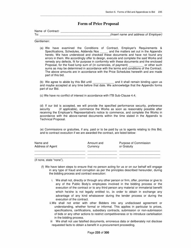
Section 6. Forms of Bid and Appendices to Bid 235 _____________________________________________________________________________________________
Page 235 of 300
Form of Price Proposal Name of Contract: ______________________________________________________________ To: ___________________________________________(Insert name and address of Employer) ___________________________________________________ Gentlemen:
(a) We have examined the Conditions of Contract, Employer's Requirements & Specifications, Schedules, Addenda Nos _____ and the matters set out in the Appendix hereto. We have understood and checked these documents and have not found any errors in them. We accordingly offer to design, execute and complete the said Works and remedy any defects, fit for purpose in conformity with these documents and the enclosed Proposal, for the fixed lump sum of (in currencies, of payment) _________ or other such sums as may be determined in accordance with the terms and conditions of the Contract. The above amounts are in accordance with the Price Schedules herewith and are made part of this bid.
(b) We agree to abide by this Bid until _____________ and it shall remain binding upon us and maybe accepted at any time before that date. We acknowledge that the Appendix forms part of our Bid.
(c) We have no conflict of interest in accordance with ITB Sub-Clause 4.4;
(d) If our bid is accepted, we will provide the specified performance security, preference security (if applicable), commence the Works as soon as reasonably possible after receiving the Employer's Representative's notice to commence, and complete the Works in accordance with the above-named documents within the time stated in the Appendix to Technical Proposal.
(e) Commissions or gratuities, if any, paid or to be paid by us to agents relating to this Bid, and to contract execution if we are awarded the contract, are listed below:
Name and Amount and Purpose of Commission Address of Agent Currency or Gratuity _______________________________ __________________ _________________________ _______________________________ __________________ _________________________ _______________________________ __________________ _________________________ (if none, state “none”).
(f) We have taken steps to ensure that no person acting for us or on our behalf will engage
in any type of fraud and corruption as per the principles described hereunder, during the bidding process and contract execution:
i. We shall not, directly or through any other person or firm, offer, promise or give to
any of the Public Body’s employees involved in the bidding process or the execution of the contract or to any third person any material or immaterial benefit which he/she is not legally entitled to, in order to obtain in exchange any advantage of any kind whatsoever during the tender process or during the execution of the contract.
ii. We shall not enter with other Bidders into any undisclosed agreement or understanding, whether formal or informal. This applies in particular to prices, specifications, certifications, subsidiary contracts, submission or non-submission of bids or any other actions to restrict competitiveness or to introduce cartelisation in the bidding process.
iii We shall not use falsified documents, erroneous data or deliberately not disclose requested facts to obtain a benefit in a procurement proceeding.

Section 6. Forms of Bid and Appendices to Bid 236 _____________________________________________________________________________________________
Page 236 of 300
We understand that transgression of the above is a serious offence and appropriate actions will be taken against such bidders.
(g)We understand that:- a. you are not bound to accept the lowest or any bid you may receive; and
b. this bid, together with your written acceptance, shall constitute a binding contract
between us, until a formal contract is prepared and executed.
We are, Gentlemen Yours faithfully Signature ___________________ in the capacity of __________ duly authorized to sign bids for and on behalf of ________________________________________________________________ Address __________________________________________ __________________________________________ Date _____________________________________

Section 6. Forms of Bid and Appendices to Bid 237 _____________________________________________________________________________________________
Page 237 of 300
Appendix to Price Proposal
Bidders should fill in the remaining blank spaces in the Appendix. Bidders are required to sign each page of the Appendix to Bid.
Conditions of Contract Sub-Clause
Parties and Persons 1.1.2.2 Employer is: Tanathi Water Services Board
Communications 1.3(a) Agreed systems of electronic transmission are: E-mail and Fax
1.3(b) Address of the Employer is: THE CHIEF EXECUTIVE OFFICER Tanathi Water Services Board K.I.D.P. Building, Kalawa Road P.O. Box Private Bag Kitui Tel: +254 712 351 104
1.3(b) Address of the Contractor is:_____________________
Law and Language 1.4 Law in force governing the Contract is: Laws of Kenya
1.4 Ruling language of the Contract is: English.
1.4 Language for communication is: English.
Adjustments for Changes in Cost
13.8 See Schedule of Adjustment Data below.
Advance Payment
14.2 Total advance payment shall be: Twenty (20) % of the Accepted Contract Amount.
14.2 The advance payment shall be repaid by means of the formula:
Where:
= the amount to be recovered
= the amount of the advance which has been granted
= he amount of the proposed cumulative payments as a percentage of the original amount of the contract. This figure will exceed 20% but not exceed 80%.
. = the amount of the previous cumulative payments as a percentage of the original amount of the contract. This figure will be below 80% but not less than 20%.
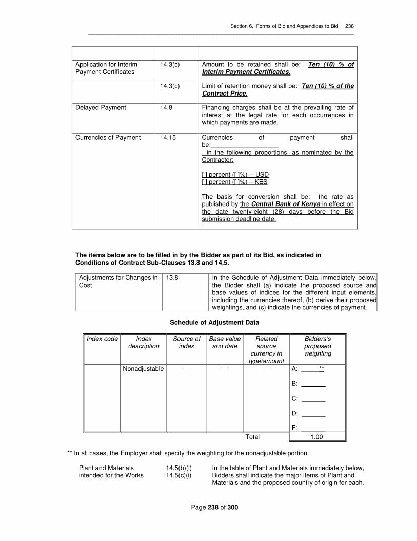
Section 6. Forms of Bid and Appendices to Bid 238 _____________________________________________________________________________________________
Page 238 of 300
Application for Interim Payment Certificates
14.3(c) Amount to be retained shall be: Ten (10) % of Interim Payment Certificates.
14.3(c) Limit of retention money shall be: Ten (10) % of the Contract Price.
Delayed Payment 14.8 Financing charges shall be at the prevailing rate of interest at the legal rate for each occurrences in which payments are made.
Currencies of Payment 14.15 Currencies of payment shall be:___________________ , in the following proportions, as nominated by the Contractor: [ ] percent ([ ]%) -- USD [ ] percent ([ ]%) – KES The basis for conversion shall be: the rate as published by the Central Bank of Kenya in effect on the date twenty-eight (28) days before the Bid submission deadline date.
The items below are to be filled in by the Bidder as part of its Bid, as indicated in Conditions of Contract Sub-Clauses 13.8 and 14.5.
Adjustments for Changes in Cost
13.8
In the Schedule of Adjustment Data immediately below, the Bidder shall (a) indicate the proposed source and base values of indices for the different input elements, including the currencies thereof, (b) derive their proposed weightings, and (c) indicate the currencies of payment.
Schedule of Adjustment Data
Index code Index description
Source of index
Base value and date
Related source
currency in type/amount
Bidders’s proposed weighting
Nonadjustable — — — A: _____** B: C: D: E:
Total 1.00
** In all cases, the Employer shall specify the weighting for the nonadjustable portion. Plant and Materials intended for the Works
14.5(b)(i) 14.5(c)(i)
In the table of Plant and Materials immediately below, Bidders shall indicate the major items of Plant and Materials and the proposed country of origin for each.

Section 6. Forms of Bid and Appendices to Bid 239 _____________________________________________________________________________________________
Page 239 of 300
Table of Plant and Materials
Item Country of Origin
For payment when shipped: Plant (list all major items) Material (list all major items) For payment when delivered to Site: Plant (list all major items) Material (list all major items)
Initials of signatory of Bid _____________________________________

Section 7. Sample Forms _____________________________________________________________________________________________
____
Page 240 of 300
Section 7. Sample Forms

Section 7. Sample Forms _____________________________________________________________________________________________
____
Page 241 of 300
Section 7. Sample Forms
Form of Bid Security (Bank Guarantee)
............................................Bank’s Name and Address of issuing Branch or Office
............................................................
Beneficiary:.................................Name and Address of Public
Body………..................................
Date: ..................................................................................................................................
BID GUARANTEE No.: ......................................................................................................
We have been informed that ......................[name of the Bidder]……...... (hereinafter called "the Bidder") has submitted to you its bid dated ....................(hereinafter called "the Bid") for the execution of .............................[name of contract] ......................... under Invitation for Bids No..........................[IFB number] ….................. (“the IFB”). Furthermore, we understand that, according to your conditions, bids must be supported by a bid security. At the request of the Bidder, we ..................................[name of Bank] ...................... hereby irrevocably undertake to pay you any sum or sums not exceeding in total an amount of ............................[amount in figures]…........................ .(..............amount in words...................) upon receipt by us of your first demand in writing accompanied by a written statement stating that the Bidder is in breach of its obligation(s) under the bid conditions, because the Bidder:
(a) has modified or withdrawn its Bid after the deadline for submission of its bid during the period of bid validity specified by the Bidder in the Form of Bid; or
(b) has refused to accept a correction of an error appearing on the face of the Bid; or
(c) having been notified of the acceptance of its Bid by the Public Body during the period of bid validity, (i) fails or refuses to sign the contract Form, if required, or (ii) fails or refuses to furnish the performance security, in accordance with the Instructions to Bidders.
This guarantee shall expire: (a) if the Bidder is the successful bidder, upon our receipt of copies of the contract signed by the Bidder and the performance security issued to you upon the instruction of the Bidder; or (b) if the Bidder is not the successful bidder, upon the earlier of (i) our receipt of a copy of your notification to the Bidder of the name of the successful bidder; or (ii) thirty days after the expiration of the Bidder’s Bid. Consequently, any demand for payment under this guarantee must be received by us at the office on or before ........................................[Public Body to insert date]................................................. This guarantee is subject to the Uniform Rules for Demand Guarantees, ICC Publication No. 758. (Applicable to overseas bidders only).
.......................................................[Bank’s seal and authorized signature(s)] .........................

Section 7. Sample Forms _____________________________________________________________________________________________
____
Page 242 of 300
Form of Contract Agreement This Agreement made this _____ day of ____________ 20 _____ between ________________ _____________________________________________________________________________ of ___________________________________________________________________________ (hereinafter called “the Employer") of the one part and __________________________________ of ____________________________________________ (hereinafter called "the Contractor") of the other part Whereas the Employer desires that the Works known as ________________________________ should be designed and executed by the Contractor, and has accepted a Bid by the Contractor for the design, execution and completion of such Works and the remedying of any defects therein. The Employer and the Contractor agree as follows: 1. In this Agreement words and expressions shall have the same meanings as are
respectively assigned to them in the Conditions of Contract hereinafter referred to. 2. The following documents shall be deemed to form and be read and construed as part
of this Agreement:
(a) The Letter of Acceptance dated ____________ (b) The Employer's Requirements (c) The Addenda nos. ___________ (d) The Bid dated _______________ (e) The Conditions of Contract (Parts I and II) (f) The completed Schedules, and (g) The Contractor's Proposal.
3. In consideration of the payments to be made by the Employer to the Contractor as
hereinafter mentioned, the Contractor hereby covenants with the Employer to design, execute and complete the Works and remedy any defects therein in conformity in all respects with the provisions of the Contract.
4. The Employer hereby covenants to pay the Contractor, in consideration of the design,
execution and completion of the Works and the remedying of defects therein, the Contract Price or such other sum as may become payable under the provisions of the Contract at the times and in the manner prescribed by the Contract.
In Witness whereof the parties hereto have caused this Agreement to be executed the day and year first before written in accordance with their respective laws. Authorized signature of Employer Authorized signature of Contractor SEAL SEAL (if any) (if any) in the presence of: in the presence of: Name ___________________________ Name ___________________________ Signature ________________________ Signature ________________________

Section 7. Sample Forms _____________________________________________________________________________________________
____
Page 243 of 300
Address _________________________ Address _________________________
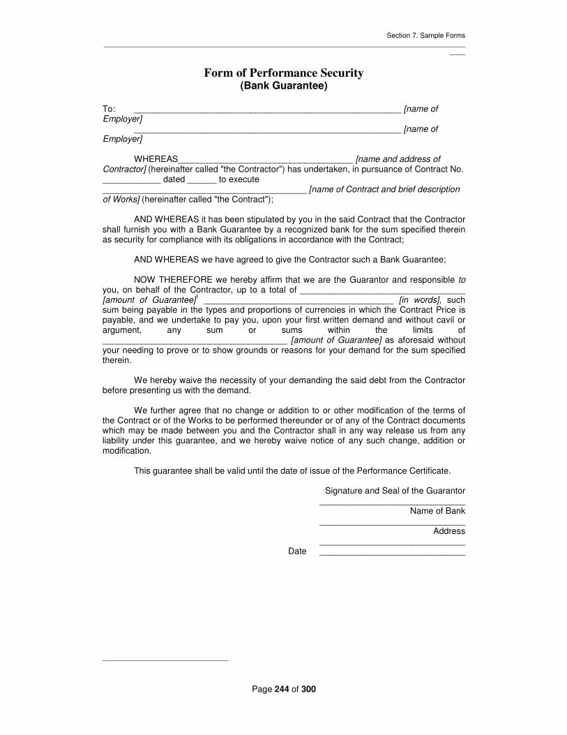
Section 7. Sample Forms _____________________________________________________________________________________________
____
Page 244 of 300
Form of Performance Security (Bank Guarantee)
To: _______________________________________________________ [name of Employer] _______________________________________________________ [name of Employer] WHEREAS____________________________________ [name and address of Contractor] (hereinafter called "the Contractor") has undertaken, in pursuance of Contract No. ____________ dated ______ to execute __________________________________________ [name of Contract and brief description of Works] (hereinafter called "the Contract"); AND WHEREAS it has been stipulated by you in the said Contract that the Contractor shall furnish you with a Bank Guarantee by a recognized bank for the sum specified therein as security for compliance with its obligations in accordance with the Contract; AND WHEREAS we have agreed to give the Contractor such a Bank Guarantee; NOW THEREFORE we hereby affirm that we are the Guarantor and responsible to you, on behalf of the Contractor, up to a total of __________________________________ [amount of Guarantee]
1 _______________________________________ [in words], such
sum being payable in the types and proportions of currencies in which the Contract Price is payable, and we undertake to pay you, upon your first written demand and without cavil or argument, any sum or sums within the limits of ______________________________________ [amount of Guarantee] as aforesaid without your needing to prove or to show grounds or reasons for your demand for the sum specified therein. We hereby waive the necessity of your demanding the said debt from the Contractor before presenting us with the demand. We further agree that no change or addition to or other modification of the terms of the Contract or of the Works to be performed thereunder or of any of the Contract documents which may be made between you and the Contractor shall in any way release us from any liability under this guarantee, and we hereby waive notice of any such change, addition or modification. This guarantee shall be valid until the date of issue of the Performance Certificate.
Signature and Seal of the Guarantor ______________________________ Name of Bank ______________________________ Address ______________________________
Date ______________________________

Section 7. Sample Forms _____________________________________________________________________________________________
____
Page 245 of 300
Form of Advance Payment Security (Bank Guarantee)
To: _____________________________________________________ [name of Employer] _____________________________________________________ [address of Employer] _____________________________________________________ [name of Contract] Gentlemen: In accordance with the provisions of the Conditions of Contract, Sub-Clause 14.2 (“Advance Payment") of the above-mentioned Contract, ________________________________ [name and Address of Contractor] (hereinafter called “the Contractor") shall deposit with ________________________________________________ [name of Employer] a bank guarantee to guarantee its proper and faithful performance under the said Clause of the Contract in an amount of _____________________________________________ [amount of Guarantee]
2 __________________________________________________________ [in
words]. We, the ____________________________ [bank], as instructed by the Contractor, agree unconditionally and irrevocably to guarantee as primary obligator and not as Surety merely, the payment to ________________________________________________ [name of Employer] on its first demand without whatsoever right of objection on our part and without its first claim to the Contractor, in the amount not exceeding __________________________________________________________ [amount of Guarantee]
1 __________________________________________________________ [in
words]. We further agree that no change or addition to or other modification of the terms of the Contract or of Works to be performed thereunder or of any of the Contract documents which may be made between _______________________________________________ [name of Employer] and the Contractor, shall in any way release us from any liability under this guarantee, and we hereby waive notice of any such change, addition or modification. This guarantee shall remain valid and in full effect from the date of the advance payment under the Contract until ________________________________________________ [name of Employer] receives full repayment of the same amount from the Contractor.
Yours truly, ______________________________________ Signature and Seal: ______________________________________
Name of Bank/Financial Institution: ______________________________________ Address: ______________________________________
Date: ______________________________________

Section 8. Schedules _____________________________________________________________________________________________
____
Page 246 of 300
Section 8. Schedules

Section 8. Schedules _________________________________________________________________________________________________
Page 247 of 300
A. SCHEDULES OF PRICES
UNITS OF MEASUREMENTS
The units of measurement described in the Bill of Quantities are metric units. Abbreviations used in the Bill of Quantities are
as follows:-
km Kilometre
m Metre
mm Millimetres
m2 Square Metre
m3 Cubic metre
mm2 Square millimetre
no/nr Number
kg Kilogramme
mg Mega-gramme (metric tonne)
l litre
ml Millilitre (cubic centimetre)
NB: The Schedules of Prices / Bill of Quanties (BQ) presented herein are derived from an indicative design.It is
therefore important to note that the winning bidder will come up with the final detailed schedule of prices/ Bill of
quantities (BQ) for construction of the project whose cost should not exceed the already quoted contract price
contained in the schedule of prices herein.

Section 8. Schedules _________________________________________________________________________________________________
Page 248 of 300

Section 8. Schedules _________________________________________________________________________________________________
Page 249 of 300

Section 8. Schedules _________________________________________________________________________________________________
Page 250 of 300

Section 8. Schedules _________________________________________________________________________________________________
Page 251 of 300

Section 8. Schedules _________________________________________________________________________________________________
Page 252 of 300

Section 8. Schedules _________________________________________________________________________________________________
Page 253 of 300

Section 8. Schedules _________________________________________________________________________________________________
Page 254 of 300
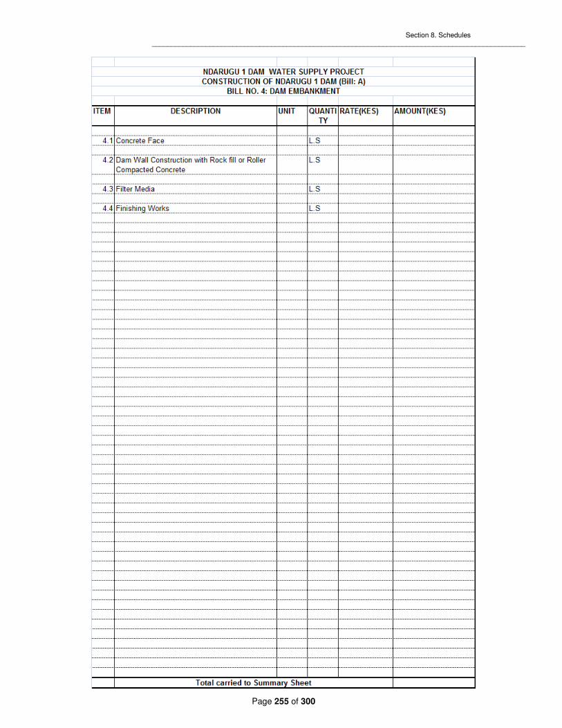
Section 8. Schedules _________________________________________________________________________________________________
Page 255 of 300

Section 8. Schedules _________________________________________________________________________________________________
Page 256 of 300

Section 8. Schedules _________________________________________________________________________________________________
Page 257 of 300

Section 8. Schedules _________________________________________________________________________________________________
Page 258 of 300

Section 8. Schedules _________________________________________________________________________________________________
Page 259 of 300

Section 8. Schedules _________________________________________________________________________________________________
Page 260 of 300

Section 8. Schedules _________________________________________________________________________________________________
Page 261 of 300

Section 8. Schedules _________________________________________________________________________________________________
Page 262 of 300

Section 8. Schedules _________________________________________________________________________________________________
Page 263 of 300

Section 8. Schedules _________________________________________________________________________________________________
Page 264 of 300

Section 8. Schedules _________________________________________________________________________________________________
Page 265 of 300

Section 8. Schedules _________________________________________________________________________________________________
Page 266 of 300
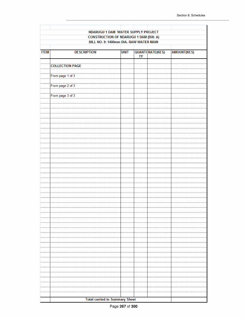
Section 8. Schedules _________________________________________________________________________________________________
Page 267 of 300

Section 8. Schedules _________________________________________________________________________________________________
Page 268 of 300

Section 8. Schedules _________________________________________________________________________________________________
Page 269 of 300
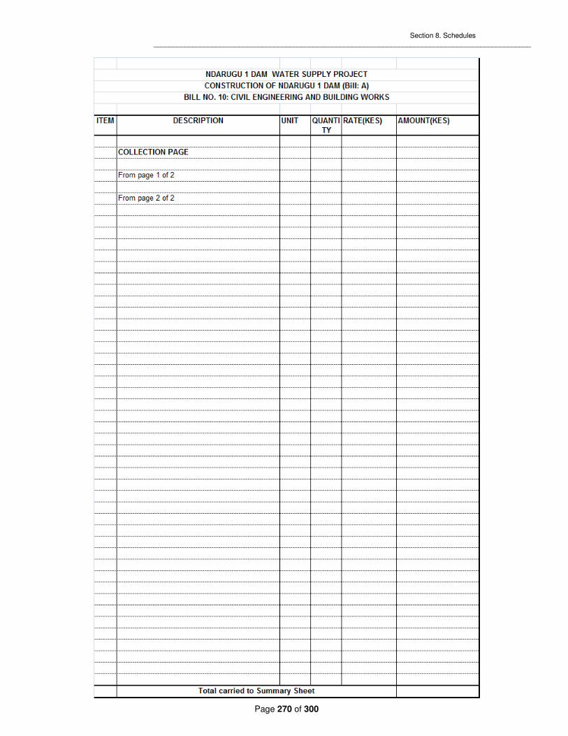
Section 8. Schedules _________________________________________________________________________________________________
Page 270 of 300

Section 8. Schedules _________________________________________________________________________________________________
Page 271 of 300
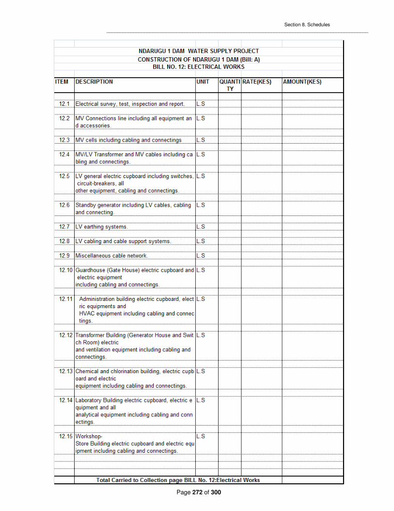
Section 8. Schedules _________________________________________________________________________________________________
Page 272 of 300

Section 8. Schedules _________________________________________________________________________________________________
Page 273 of 300

Section 8. Schedules _________________________________________________________________________________________________
Page 274 of 300

Section 8. Schedules _________________________________________________________________________________________________
Page 275 of 300

Section 8. Schedules _________________________________________________________________________________________________
Page 276 of 300

Section 8. Schedules _________________________________________________________________________________________________
Page 277 of 300

Section 8. Schedules _________________________________________________________________________________________________
Page 278 of 300

Section 8. Schedules _________________________________________________________________________________________________
Page 279 of 300

Section 8. Schedules _________________________________________________________________________________________________
Page 280 of 300

Section 8. Schedules _________________________________________________________________________________________________
Page 281 of 300

Section 8. Schedules _________________________________________________________________________________________________
Page 282 of 300

Section 8. Schedules _________________________________________________________________________________________________
Page 283 of 300

Section 8. Schedules _________________________________________________________________________________________________
Page 284 of 300

Section 8. Schedules _________________________________________________________________________________________________
Page 285 of 300

Section 8. Schedules _________________________________________________________________________________________________
Page 286 of 300

Section 8. Schedules _____________________________________________________________________________________________
____
Page 287 of 300
Price Adjustment Sample Price Adjustment Formula Prices payable to the Contractor, in accordance with the Contract, shall be subject to adjustment during performance of the Contract to reflect changes in the cost of labor and material components, in accordance with the following formula:
P P a bL
Lc
M
MP1 0
1
0
1
0
0= × + + −( )
in which: P1 = adjustment amount payable to the Contractor P0 = Contract price (base price) a = percentage of fixed element in Contract price (a = %) b = percentage of labor component in Contract price (b = %) c = percentage of material and equipment component in Contract price (c = %) L0, L1 = labor indices applicable to the appropriate industry in the country of origin on the base date and the date for adjustment, respectively M0, M1= material and equipment indices in the country of origin on the base date and the date for adjustment, respectively N.B.: a+b+c= 100%. Conditions Applicable To Price Adjustment The Bidder shall indicate the source of labor and materials indices and the base date indices in its bid. Item Source of Indices Used Base Date Indices The base date shall be the date thirty (30) days prior to the Bid closing date. The date of adjustment shall be the mid-point of the period of manufacture or installation of component or Plant. The following conditions shall apply: (a) No price increase will be allowed beyond the original delivery date unless covered by an extension of time awarded by the Employer under the terms of the Contract. No price increase will be allowed for periods of delay for which the Contractor is responsible. The Employer will, however, be entitled to any price decrease occurring during such periods of delay. (b) If the currency in which the Contract price, P0, is expressed is different from the currency of the country of origin of the labor and/or materials indices, a correction factor will be applied to avoid incorrect adjustments of the Contract price. The correction factor shall correspond to the ratio of exchange rates between the two currencies on the base date and the date for adjustment as defined above. (c) No price adjustment shall be payable on the portion of the Contract price paid to the Contractor as an advance payment.

Section 8. Schedules 288 _________________________________________________________________________________________________
Page 288 of 300
B. SCHEDULE OF PAYMENT CERTIFICATE
Item Description Unit
Billed Measured Quantities Works Value (KES)
Qty Rate
Amount Prev. Cert.
This Cert.
Total to Date
Prev. Cert.
This Cert.
Total to Date
TOTAL (To Grand Summary)

Section 8. Schedules 289 _________________________________________________________________________________________________
Page 289 of 300
Grand Summary
Item Description
Billed Measured Quantities Works Value (KES)
Amount Prev. Cert.
This Cert.
Total to Date
Prev. Cert.
This Cert.
Total to Date
GRAND TOTAL

Section 8. Schedules 290 _____________________________________________________________________________________________
____
Page 290 of 300
C. SCHEDULE OF COEFFICIENT AND INDICES FOR PRICE ADJUSTMENT
Coefficient Scope of Index
Country of Origin; Currency of Index
Source of Index; Title/Definition
Value on stated dates
Value Date a = _______ ________ b = _______ ________ c = _______ ________ d = _______ ________ e = _______ ________

Section 8. Schedules 291 _____________________________________________________________________________________________
____
Page 291 of 300
D. SCHEDULE OF MAJOR ITEMS OF CONSTRUCTIONAL PLANT
Description
(Type, Model, Make)
No. of
Each
Year of
Manufacture
New or
Used
Owned (O) Or
Leased (L)
CIF Value
Est. Power Rating
Capacity t or m
3
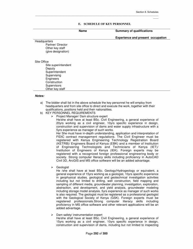
Section 8. Schedules _____________________________________________________________________________________________
____
Page 292 of 300
E. SCHEDULE OF KEY PERSONNEL
Name Summary of qualifications
Experience and present occupation
Headquarters Partner/ Director Other key staff (give designation)
Site Office Site superintendent Deputy Superintendent Supervising Engineers Construction Supervisors Other key staff
Notes:
a) The bidder shall list in the above schedule the key personnel he will employ from headquarters and from site office to direct and execute the work, together with their qualifications, positions held and their nationalities.
b) KEY PERSONNEL REQUIREMENTS � Project Manager/ Dam structure expert
He/she shall have at least BSc. Civil Engineering, a general experience of 20yrs working as a civil engineer, 10yrs specific experience in design, construction and supervision of dams and water supply infrastructure with a 5yrs experience as manager of such works. He/ She must have in-depth understanding, application and interpretation of FIDIC contract management regulations. The Civil Engineer must be registered with Kenya Engineering Technology Registration Board (KETRB)/ Engineers Board of Kenya (EBK) and a member of Institution of Engineering Technologists and Technicians of Kenya (IET)/ Institution of Engineers of Kenya (IEK). Foreign experts may be registered with a recognized foreign professional engineering body or society. Strong computer literacy skills including proficiency in AutoCAD Civil 3D, ArcGIS and MS office software will be an added advantage.
� Geologist He /she shall have at least BSc. Geology/Hydrogeology or equivalent, a general experience of 15yrs working as a geologist, 10yrs specific experience in geophysical studies, geological and geotechnical investigation activities including but not limited to drilling, well construction, field mapping and sampling of different media, groundwater planning, investigation, exploration, abstraction, and development, and yield analysis, groundwater modeling including storage model analysis. 5yrs experience as manager of such works is also required. The geologist must be registered as a professional geologist with the Geological Society of Kenya (GSK). Foreign experts must be registered professionals.Strong computer literacy skills including proficiency in MS office software and other relevant applications will be an added advantage.
� Dam safety/ instrumentation expert He/she shall have at least BSc. Civil Engineering, a general experience of 15yrs working as a civil engineer, 10yrs specific experience in design, construction and supervision of dams, including but not limited to inspecting

Section 8. Schedules _____________________________________________________________________________________________
____
Page 293 of 300
and monitoring various dam parameters through instrumentation like; pore pressure, displacement, seepage, strains, stresses, dynamic load, uplift pressure, temperature, groundwater pressure, deformation, seismic events, leakage, water levels for ensuring adequate safety & margin of safety with 5yrs experience as manager of such works. He/ She must have in-depth understanding, application and interpretation of FIDIC contract management regulations. The Civil Engineer must be registered with Kenya Engineering Technology Registration Board (KETRB)/ Engineers Board of Kenya (EBK) and a member of Institution of Engineering Technologists and Technicians of Kenya (IET)/ Institution of Engineers of Kenya (IEK). Foreign experts may be registered with a recognized foreign professional engineering body or society. Strong computer literacy skills including proficiency in AutoCAD Civil 3D, ArcGIS and MS office software will be an added advantage.
� Site Agent He/she shall have at least BSc. Civil Engineering, a general experience of 15yrs working as a civil engineer, 10yrs specific experience in overseeing operations on a dam site and water supply infrastructure including but not limited to a day-to-day basis and ensuring that work is done safely, on time and within budget and to the right quality standards and specifications and with 5yrs experience as a construction manager of such works. He/ She must have in-depth understanding, application and interpretation of FIDIC contract management regulations. The Civil Engineer must be registered with Kenya Engineering Technology Registration Board (KETRB)/ Engineers Board of Kenya (EBK) and a member of Institution of Engineering Technologists and Technicians of Kenya (IET)/ Institution of Engineers of Kenya (IEK). Foreign experts may be registered with a recognized foreign professional engineering society or body. Strong computer literacy skills including proficiency in AutoCAD Civil 3D, ArcGIS and MS office software will be an added advantage.
� Materials Engineer He/she shall have at least BSc. Civil Engineering or equivalent, a general experience of 10yrs working as a materials engineer, 5yrs specific experience in quality control processes in construction of dams and water supply infrastructure which includes but not limited to analysis of soils, concrete, asphalt, bitumen, cement and mortar, steel, aggregates, and other materials used in civil engineering to ensure quality control for the works. A 3yrs experience as a manager of such works is a prerequisite. He/ She must have in-depth understanding, application and interpretation of FIDIC contract management regulations. The Civil Engineer must be registered with Kenya Engineering Technology Registration Board (KETRB)/ Engineers Board of Kenya (EBK) and a member of Institution of Engineering Technologists and Technicians of Kenya (IET)/ Institution of Engineers of Kenya (IEK). Foreign experts may be registered with a recognized foreign professional engineering society or body. Strong computer literacy skills including proficiency in AutoCAD, ArcGIS and MS office software will be an added advantage.
� Site Measurements Engineer/ Quantity Surveyor He/she shall have at least BSc. Civil Engineering, a general experience of 10yrs working as a civil engineer, 5yrs specific experience in overseeing operations and taking measurements/ quantifying works on a dam site and water supply infrastructure on a day-to-day basis including but not limited to ensuring that work is done safely, on time and within budget and to the right quality/quantity standards and specifications and with a 3yrs experience as a manager of such works. He/ She must have in-depth understanding, application and interpretation of FIDIC contract management regulations. The Civil Engineer must be

Section 8. Schedules _____________________________________________________________________________________________
____
Page 294 of 300
registered with Kenya Engineering Technology Registration Board (KETRB)/ Engineers Board of Kenya (EBK) and a member of Institution of Engineering Technologists and Technicians of Kenya (IET)/ Institution of Engineers of Kenya (IEK). Foreign experts may be registered with a recognized foreign professional engineering society or body. Strong computer literacy skills including proficiency in AutoCAD Civil 3D, ArcGIS and MS office software will be an added advantage.
� Site Engineering Surveyor He /she shall have at least BSc. Engineering Survey or a Bachelors Degree in a closely related field, a general experience of 10yrs working as a surveyor, 5yrs specific experience including but not limited to conducting construction survey, control, guidance, setting-out, as-built for dams & water supply infrastructure projects while performing quality control of construction to ensure the project progresses according to the design and given tolerances. A 3yrs experience as a manager of such works is necessary. The surveyor must be registered with the relevant professional body, society or institution. The surveyor should be conversant in operating the latest total station, digital level, GPS and all other necessary survey equipment. Strong computer literacy skills including proficiency in AutoCAD Civil 3D, ArcGIS, LISCAD and MS office software will be an added advantage.
� Environmental specialist He /she shall have at least a BSc in Environmental Science or equivalent, a general experience of 10yrs working as an environmentalist, 5 yrs specific experience in dams and water supply projects including but not limited to ensuring that the construction methods are in line with the existing environmental laws/regulations, conducting EIA and RAP studies, supervising & monitoring the implementation of environmental mitigation measures required, and with 3yrs experience as manager of such works.The environmentalist must be registered with NEMA as a lead expert. Foreign experts may be reistered with an equivalent foreign professional body or institution. Strong computer literacy skills including proficiency in ArcGIS and MS office will be an added advantage.
� Hydraulic Engineer He/she shall have at least BSc. Civil Engineering, or an equivalent Engineering Degree, a general experience of 10yrs working as an engineer, 5yrs specific experience in performing engineering activities including but not limited to water distribution, treatment, storm water, modeling, evaluations, investigations, planning, design and construction of dams and water supply infrastructure with 3yrs experience as manager of such works.
He/ She must have in-depth understanding, application and interpretation of FIDIC contract management regulations. The Engineer must be registered with Kenya Engineering Technology Registration Board (KETRB)/ Engineers Board of Kenya (EBK) and a member of Institution of Engineering Technologists and Technicians of Kenya (IET)/ Institution of Engineers of Kenya (IEK). Foreign experts may be registered with a recognized foreign professional engineering body or society. Strong computer literacy skills including proficiency in AutoCAD Civil 3D, ArcGIS and MS office software will be an added advantage.
� Social Economist
He/she shall have atleast Bsc. Degree in socioeconomics or an equivalent degree, a general experience of 10yrs working as a socioeconomist, 5yrs

Section 8. Schedules _____________________________________________________________________________________________
____
Page 295 of 300
specific experience in urban social dynamics including but not limited to water service provision in informal settlements, social work, gender issues, community mobilization and Sanitation Promotion and Hygiene Education and training of social workers / community members on sustainability of the water supply systems with 3yrs experience as manager of such works.
Strong computer literacy skills including proficiency in MS office software will be an added advantage.
� Hydrologist He /she shall have at least a BSc in Hydrology or equivalent, a general experience of 10yrs working as Hydrologist, 5 yrs specific experience in dams and water supply projects including but not limited to employing statistical and hydrological modeling techniques, testing for certain water properties such as Ph /pollution levels, producing water and drought management plans, ensuring implementation of appropriate regulations, with 3yrs experience as manager of such works.The Hydrologist must be a registered professional whether foreign or local. Strong computer literacy skills including proficiency in ArcGIS and MS office software will be an added advantage.
� Water treatment specialist He /she shall have at least a BSc in Water technology or equivalent, a general experience of 10yrs working as a water treatment specialist, 5 yrs specific experience in dams and water supply projects including but not limited to performing and overseeing water quality analysis, testing & verification, assisting in setup, operating and maintaining of water treatment works, maintaining logs of water facilities which may include Ph levels, chlorine content, temperatures & concentrations. 3yrs experience as manager of such works is necessary.The specialist must be a registered professional whether foreign or local. Strong computer literacy skills including proficiency in ArcGIS and MS office software will be an added advantage.
� Structural Engineer He/she shall have at least BSc. Civil Engineering, a general experience of 10yrs working as a structural engineer, 5yrs specific experience in design, construction and supervision of dams and water supply infrastructure with 3yrs experience as manager of such works.
He/ She must have in-depth understanding, application and interpretation of FIDIC contract management regulations. The Engineer must be registered with Kenya Engineering Technology Registration Board (KETRB)/ Engineers Board of Kenya (EBK) and a member of Institution of Engineering Technologists and Technicians of Kenya (IET)/ Institution of Engineers of Kenya (IEK). Foreign experts may be registered with a recognized foreign professional engineering body or society.
Strong computer literacy skills including proficiency in AutoCAD Civil 3D, ArcGIS and MS office software will be an added advantage.
� Site Electrical/ Mechanical Engineer He/she shall have at least BSc. Mechanical Engineering or equivalent
engineering degree, a general experience of 10yrs working as

Section 8. Schedules _____________________________________________________________________________________________
____
Page 296 of 300
electromechanical engineer, 5yrs specific experience in design of water
resources development projects with a 3yrs experience as manager of such
works.
He/ She must have in-depth understanding, application and interpretation of FIDIC contract management regulations. The Engineer must be registered with Kenya Engineering Technology Registration Board (KETRB)/ Engineers Board of Kenya (EBK) and a member of Institution of Engineering Technologists and Technicians of Kenya (IET)/ Institution of Engineers of Kenya (IEK). Foreign experts may be registered with a recognized foreign professional engineering body or society.
Strong computer literacy skills including proficiency in AutoCAD and MS office software will be an added advantage.
c) Curriculum Vitae(CV) format for KEY PERSONNEL
Position Title (e.g., Water Engineer) Name of Expert (Insert full name) Date of Birth (day/month/year) Country of Citizenship/ Residence Education: (List college/university or other specialized education, giving names of
educational institutions, dates attended, degree(s)/ diploma(s) obtained)
Employment record relevant to the assignment: (Starting with present position, list in
reverse order. Please provide dates, name of employing organization, titles of positions held,
types of activities performed and location of the assignment, and contact information of
previous clients and employing organization(s) who can be contacted for references. Past
employment that is not relevant to the assignment does not need to be included)
Period Employing
organization and your title/position. Contact information for references
Country Summary of activities performed relevant to the Assignment
(e.g., May 2005- present)
(e.g., Ministry of……, advisor/ consultant to…. For references: Tel……/e-mail…..; Mr. Hbbb, deputy minister)
Membership in Professional Associations and Publications:

Section 8. Schedules _____________________________________________________________________________________________
____
Page 297 of 300
Language skills (indicate only languages in which you can work):_____________________ Adequacy for the Assignment: Detailed Tasks Assigned on Expert:
Reference to Prior Work/Assignments that Best Illustrates Capability to Handle the Assigned Tasks
(List all deliverables/ tasks in which the Expert will be involved)
Expert’s contact information: (e-mail……………………, phone…………………….) Certification:
I, the undersigned, certify that to the best of my knowledge and belief, this CV correctly
describes myself, my qualifications, and my experience, and I am available to undertake the
assignment in case of an award. I understand that any misstatement or misinterpretation
described herein may lead to my disqualification or dismissal by the Client.
_______________________________________________________________ (day/month/year) Name of Expert Signature Date _______________________________________________________________ (day/month/year) Name of authorized Representative of the Contractor (the same who signs the Bidding Document)
Signature Date

Section 8. Schedules _____________________________________________________________________________________________
____
Page 298 of 300
F. SCHEDULE OF SUBCONTRACTORS
Statement of Similar Element of Approximate Value Name and Address Works Previously Work of Subcontractor Executed

Section 9. Drawings _____________________________________________________________________________________________
____
Page 299 of 300
Section 9. Drawings

Section 9. Drawings _____________________________________________________________________________________________
____
Page 300 of 300
Section 9. Drawings
Bidder(s) to submit conceptual drawings in atleast A3 paper size to help explain their conceptual designs.