ndt standards for additive manufacturing · • triaging through ndt (natep) • crp –phase 2...
TRANSCRIPT

NDT Standards for Additive Manufacturing
Grenoble, France
9th - 10th April 2018PMO-003-F7(v2)
Ben Dutton
Mohd Hashimi Rosli
David Ross-Pinnock
Workshop on Additive Manufacturing (WAM 2018)
Overview
The MTC
Background
Scope of the standard
Work completed to date
Summary
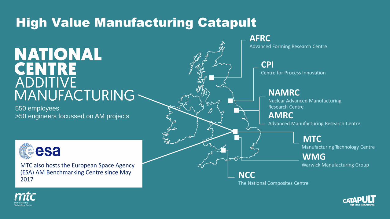
AFRCAdvanced Forming Research Centre
CPICentre for Process Innovation
NAMRCNuclear Advanced ManufacturingResearch Centre
AMRCAdvanced Manufacturing Research Centre
MTCManufacturing Technology Centre
WMGWarwick Manufacturing Group
NCCThe National Composites Centre
MTC also hosts the European Space Agency (ESA) AM Benchmarking Centre since May 2017
550 employees
>50 engineers focussed on AM projects
High Value Manufacturing Catapult

Catapult Aim: Bridge the Valley of Death
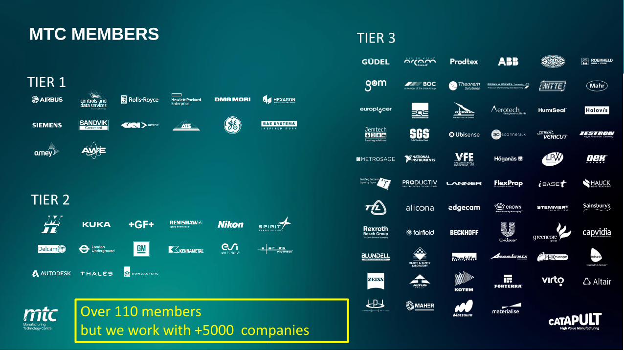
TIER 1
TIER 2
TIER 3
Over 110 members but we work with +5000 companies
MTC MEMBERS
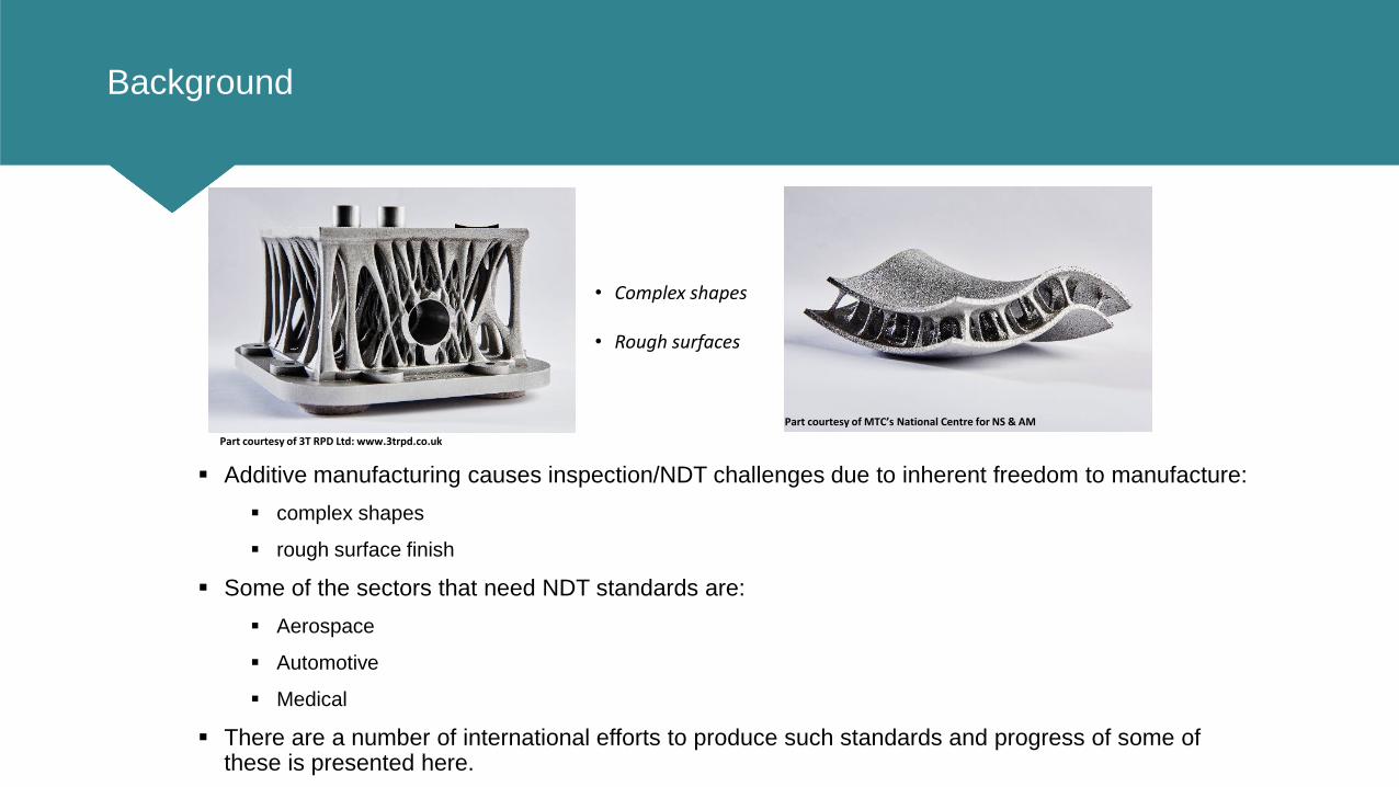
Background
Additive manufacturing causes inspection/NDT challenges due to inherent freedom to manufacture:
complex shapes
rough surface finish
Some of the sectors that need NDT standards are:
Aerospace
Automotive
Medical
There are a number of international efforts to produce such standards and progress of some of these is presented here.
Part courtesy of 3T RPD Ltd: www.3trpd.co.uk
Part courtesy of MTC’s National Centre for NS & AM
• Complex shapes
• Rough surfaces

Background
AM offers many design opportunities, but presents many inspection challenges.
NDT of AM parts is vital to ensure:
Safety;
Performance;
Reliability;
Process confidence.
A range of defects can occur - some of which are unique to AM.
Inspection is challenging due to complex geometries and accessibility of features.
Artefacts can be designed and built in different materials to test NDT technologies.
Standards are urgently required for industry to confidently adopt AM processes.

BackgroundProject Timeline
EU FP7 –AMAZE Project
CRP –NDT Standard for AM (Phase 1)
GE Power
Triaging through NDT (NATEP)
CRP –NoSFAM(Phase 2)
Various projects have been carried out by the MTC, and in collaboration with
others, to define standards for NDT in AM since 2015.

BackgroundProject Timeline
2013 - 2016 2015 - 2016 2016 -2017 2017- 2018 2018
Supporting
project
EU FP7 -
AMAZE
CRP – NDT Standard for
Additive Manufacturing -
Phase 1
• GE- Power
• AMAZE
• Triaging through NDT
(NATEP)
• CRP – Phase 2
(NoSFAM)
• MTC internal project
• Industrial partners
volunteer to build
artefacts using different
materials.
• NDT partners volunteer to
trial built artefacts.
Feedback from AM
manufacturer and
NDT partners.
Task To rapidly
produce
large
defect-free
additively-
manufactur
ed
components
.
• Create defects library
based on information
from AMAZE
• Review existing
standards
• Create standard
artefact design
• Refine design of artefact
• Build artefact
• XCT trial
• Cut-up & micro XCT
• Validation
• Design 2nd iteration
• Update standard
document
• Build 2nd iteration artefact
• Trial with other NDT
methods
• Validation
• Update standard
document
• Incorporate
feedback into
standards
document
• Complete
document
• Submit final draft
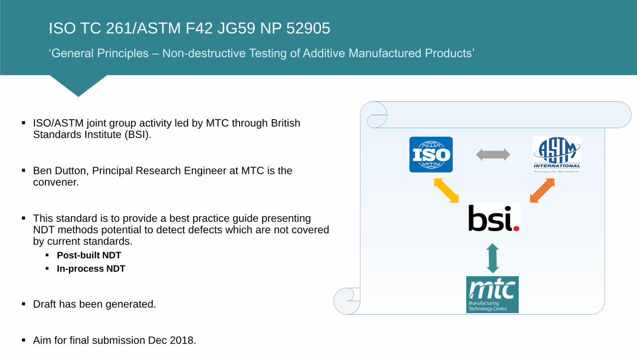
ISO TC 261/ASTM F42 JG59 NP 52905
‘General Principles – Non-destructive Testing of Additive Manufactured Products’
ISO/ASTM joint group activity led by MTC through British Standards Institute (BSI).
Ben Dutton, Principal Research Engineer at MTC is the convener.
This standard is to provide a best practice guide presenting NDT methods potential to detect defects which are not covered by current standards.
Post-built NDT
In-process NDT
Draft has been generated.
Aim for final submission Dec 2018.
MTC
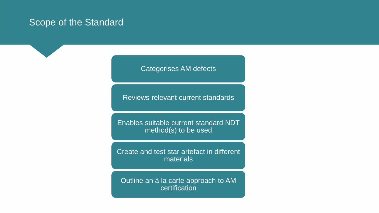
Scope of the Standard
Categorises AM defects
Reviews relevant current standards
Enables suitable current standard NDT method(s) to be used
Create and test star artefact in different materials
Outline an à la carte approach to AM certification

Classification of AM Defects
Causes Mode of failure Defects
For NDT what is important is the defect morphology and the following are unique to AM:
1. Layer2. Cross-layer3. Unconsolidated
powder4. Trapped powder5. Inclusion6. Layer shift
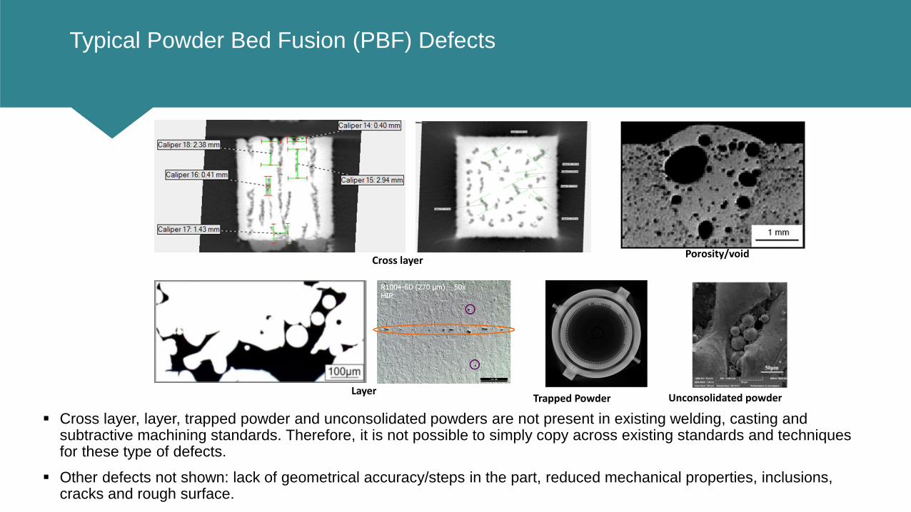
Typical Powder Bed Fusion (PBF) Defects
Cross layer, layer, trapped powder and unconsolidated powders are not present in existing welding, casting and subtractive machining standards. Therefore, it is not possible to simply copy across existing standards and techniques for these type of defects.
Other defects not shown: lack of geometrical accuracy/steps in the part, reduced mechanical properties, inclusions, cracks and rough surface.
Trapped PowderLayer
Cross layerPorosity/void
Unconsolidated powder

Typical Direct Energy Deposition (DED) Defects
Poor surface finish
Porosity
Incomplete fusion
.
Undercuts at the toe of the welds between adjoining weld beads
Hole or void
Cracking
Other defects: lack of geometrical accuracy/steps in the part, non-uniform weld bead and fusion characteristics and
inclusions.
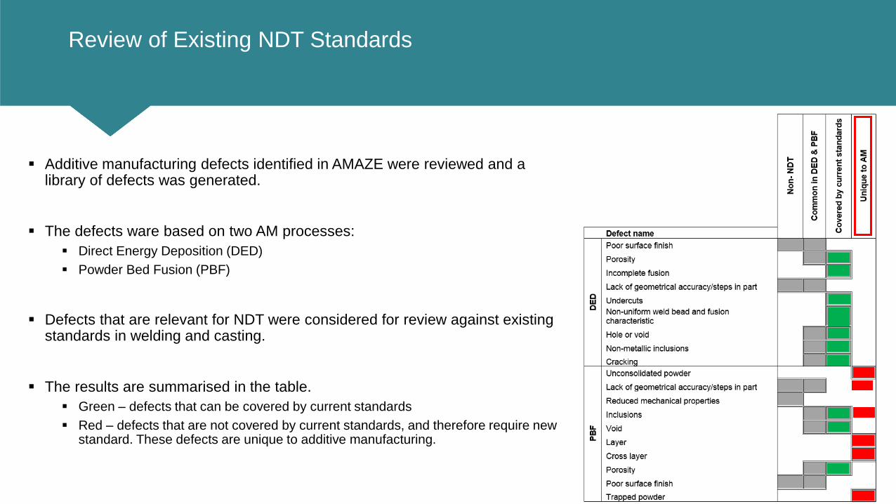
Review of Existing NDT Standards
Additive manufacturing defects identified in AMAZE were reviewed and a library of defects was generated.
The defects ware based on two AM processes:
Direct Energy Deposition (DED)
Powder Bed Fusion (PBF)
Defects that are relevant for NDT were considered for review against existing standards in welding and casting.
The results are summarised in the table.
Green – defects that can be covered by current standards
Red – defects that are not covered by current standards, and therefore require new standard. These defects are unique to additive manufacturing.
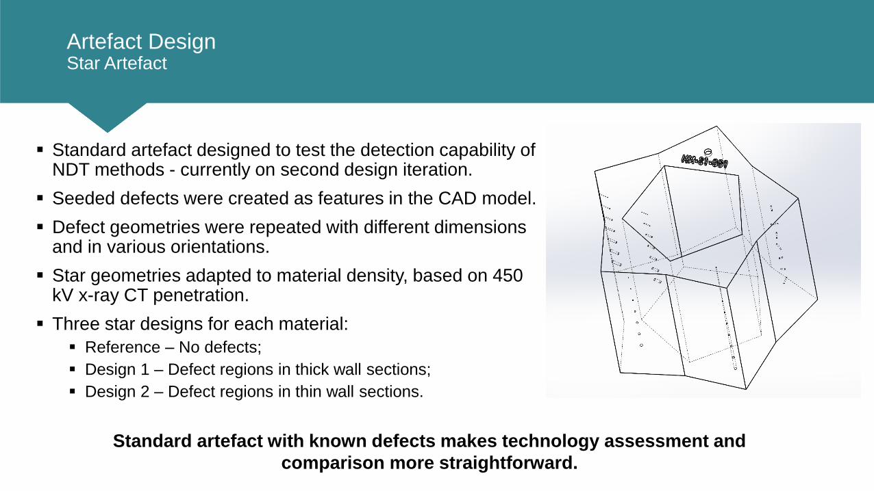
Artefact DesignStar Artefact
Standard artefact designed to test the detection capability of NDT methods - currently on second design iteration.
Seeded defects were created as features in the CAD model.
Defect geometries were repeated with different dimensions and in various orientations.
Star geometries adapted to material density, based on 450 kV x-ray CT penetration.
Three star designs for each material:
Reference – No defects;
Design 1 – Defect regions in thick wall sections;
Design 2 – Defect regions in thin wall sections.
Standard artefact with known defects makes technology assessment and
comparison more straightforward.

Artefact Design (S1)Star Artefact – Version 1
• Defect regions in thick wall
sections;
• Design shown for Hastelloy-X;
• Hastelloy-X very dense, so is
smaller in form relative to less
dense materials;
• All samples printed are serialised
for tracking through trials;

Artefact Design (S2)Star Artefact – Version 2
• Defect regions in thin wall
sections;
• Design 2 hypothesised to be
possibly easier to inspect for
some technologies due to less
wall penetration required;
• Conversely, defects in thin wall
sections may be subject to more
build error.
• Design shown for Hastelloy-X;
• Hastelloy-X very dense, so is
smaller in form relative to less
dense materials;
• All samples printed are serialised
for tracking through trials;
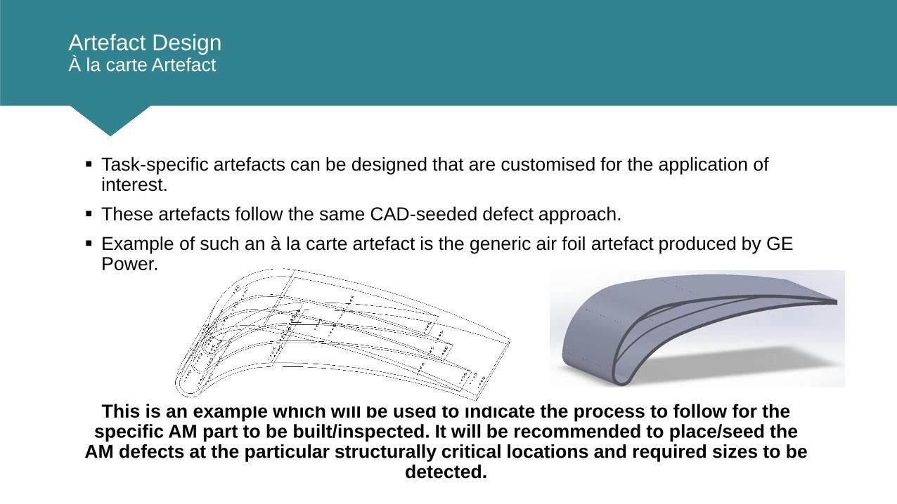
Artefact DesignÀ la carte Artefact
Task-specific artefacts can be designed that are customised for the application of interest.
These artefacts follow the same CAD-seeded defect approach.
Example of such an à la carte artefact is the generic air foil artefact produced by GE Power.
This is an example which will be used to indicate the process to follow for the specific AM part to be built/inspected. It will be recommended to place/seed the
AM defects at the particular structurally critical locations and required sizes to be detected.
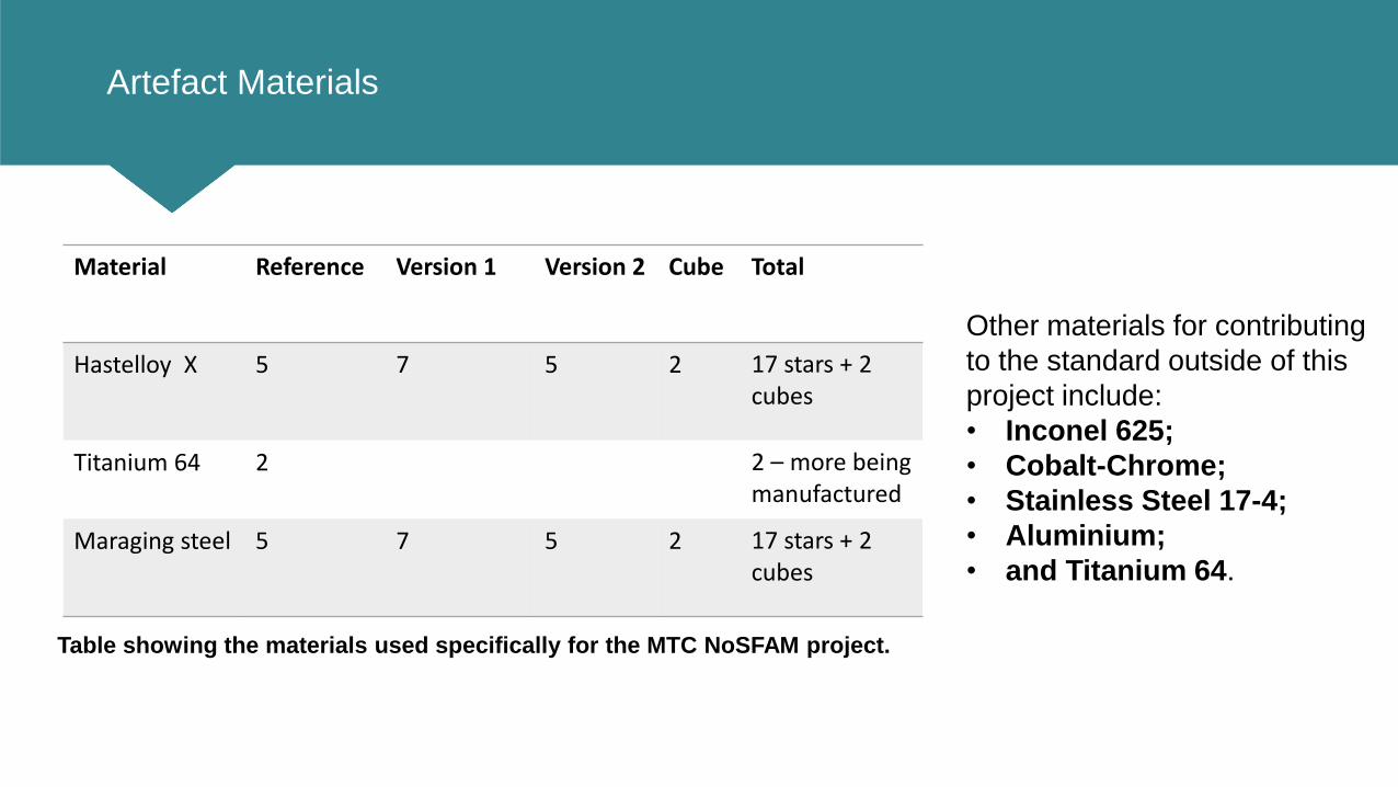
Artefact Materials
Material Reference Version 1 Version 2 Cube Total
Hastelloy X 5 7 5 2 17 stars + 2 cubes
Titanium 64 2 2 – more being manufactured
Maraging steel 5 7 5 2 17 stars + 2 cubes
Other materials for contributing
to the standard outside of this
project include:
• Inconel 625;
• Cobalt-Chrome;
• Stainless Steel 17-4;
• Aluminium;
• and Titanium 64.
Table showing the materials used specifically for the MTC NoSFAM project.

NDT Trials
XCTResonance
Testing (PCRTand Non-linear)
Ultrasonic Testing
• Single probe immersion
• Phased array/full matrix capture
ThermographyNon-linear Acoustic
Radiography
Neutron Tomography
/Synchrotron
Trials of various NDT technologies with the artefacts are on-going.
Trials carried out in collaboration with:
end users;
universities;
instrument vendors;
and national measurement institutes (NMIs).

Standard Artefact Activity
NDT methods Artefact build
Post-buildIn-process monitoring
recommendation PBF
Association Neutron/Synchrotron Metrology Digital/live X-ray X-ray CT Flash Thermography Resonant/nonlinear testing Ultrasound SLM EBM
ISO X X X
BSI/ISO X
ISO/ConceptLaser X X ?
ISO X X
ISO X
ISO/ANSI
ASTM
ASTM
ASTM
US Navy
UL
TWI X
NPL
STFC
UoN X
UoBirm ?
Theta Tec. X
UoS ?
Encodema3D X
GE X
X
RENISHAW
BAE Systems X X
GE Power X X
IIL/BAM X X
ESRF X
NSI X
NASA X X?
ConceptLaser/GE
Parker
NPL
RR
Project AMAZE X X

Hastelloy-X Star Artefacts (S1, S2 and no defects)Manufacture
• Star artefacts presented here manufactured in
Hastelloy-X.
• Laser powder bed fusion with 100 µm layer height.
• Hastelloy-X geometry based on nearest density material
Nickel from XCT standard (10% transmission).
• Powder removal achieved using ultrasonic bath.
Photographs of the Hastelloy-X samples.

Hastelloy-X Star Artefacts (S1)XCT Inspection
• Artefacts have been inspected using
the Nikon XTH 450 system, and
Volume Graphics VGStudioMAX.
• Defect detection of defects greater
that 100 µm.
• Promising ability to resolve trapped
powder defects.
Photograph of the Nikon XTH 450 (Nikon, 2018). Quad-view from VGStudioMAX of the XCT scan (layer defects).
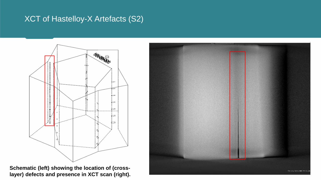
XCT of Hastelloy-X Artefacts (S2)
Schematic (left) showing the location of (cross-
layer) defects and presence in XCT scan (right).

XCT of Hastelloy-X Artefacts (S2)
Schematic (left) showing the location of (unconsolidated
powder) defects and presence in XCT scan (right).

XCT of Hastelloy-X Artefact (S1) Defects Built/Detected
Version Region Description Defect Detected- Y/N
S1
1Cylinders, length 2 mm, equal diameter Ø =
0.30 mm, vary angle orientation
45 deg 1st Y
45 deg 2nd Y
45 deg 3rd Y
45 deg 4th Y
horizontal (radial) Y
horizontal (tangential) N
vertical Y
2 Vertical cylinders, length 5 mm, vary Ø
0.7 Y
0.6 Y
0.5 Y
0.4 Y
0.3 Y
0.2 N
0.1 N
3 Spheres with trapped powder. Vary Ø.
0.7 Y
0.6 Y
0.5 Y
0.4 Y
0.3 Y
0.2 N
0.1 N
4Horizontal cylinders, from outside, length 3
mm, vary Ø
0.7 Y
0.6 Y
0.5 Y
0.4 Y
0.3 Y
0.2 N
0.1 N
5 Horizontal cylinders, length 2 mm, vary Ø
0.7 Y
0.6 Y
0.5 Y
0.4 Y
0.3 Y
0.2 N
0.1 N
Other NDT Standard Developments
ASTM E07 WK47031 ‘Standard Guide for NDT of AM Metal Parts Used in Aerospace Applications’
I helped initiate and I am currently participating as an NDT expert
SAE AMS7003 ‘Laser Powder Bed Fusion Process’
I am participating in the NDT section

Summary
• Rapid growth in application of AM processes is driving demand for inspection
standards.
• A new NDT standard for AM based upon artefacts with seeded defects has been
proposed, and is being drafted.
• An application-specific à la carte artefact format is proposed to be followed for
your specific part design.
• Trials have been carried out to:
• Validate the seeded artefact defect design;
• Assess a range of NDT techniques.
• The standard will be submitted for review at the end of 2018
Realising the full potential of AM will depend upon the definition and
acceptance of comprehensive industrial standards.
