nec versa lx notebook computer versa lx · nec csd utilities ... lcd liquid crystal display lsb...
TRANSCRIPT
NEC Versa® LX Notebook Computer
VERSA LX
S E R V I C E A N D R E F E R E N C EM A N U A L

First Printing — March 1999
Copyright 1999NEC Computer Systems Division
Packard Bell NEC, Inc.1 Packard Bell Way
Sacramento, CA 95828-0903All Rights Reserved
Proprietary Notice and Liability Disclaimer
The information disclosed in this document, including all designs and related materials, is thevaluable property of NEC Computer Systems Division, Packard Bell NEC, Inc. (hereinafter“NEC CSD”) and/or its licensors. NEC CSD and/or its licensors, as appropriate, reserve all patent,copyright and other proprietary rights to this document, including all design, manufacturing,reproduction, use, and sales rights thereto, except to the extent said rights are expressly granted toothers.
The NEC CSD product(s) discussed in this document are warranted in accordance with the terms ofthe Warranty Statement accompanying each product. However, actual performance of each suchproduct is dependent upon factors such as system configuration, customer data, and operatorcontrol. Since implementation by customers of each product may vary, the suitability of specificproduct configurations and applications must be determined by the customer and is not warrantedby NEC CSD.
To allow for design and specification improvements, the information in this document is subject tochange at any time, without notice. Reproduction of this document or portions thereof without priorwritten approval of NEC CSD is prohibited.
FaxFlash is a service mark of NEC Computer Systems Division (NEC CSD), Packard Bell NEC, Inc.NEC is a registered trademark of NEC Corporation, used under license.ENERGY STAR is a U.S. registered mark.All other product, brand, or trade names used in this publication are the trademarks or registered trademarks of their
respective trademark owners.
Contents iii
Contents
Preface ................................................................................................................................... viiAbbreviations.......................................................................................................................... ix
Chapter 1 System OverviewGetting to Know the NEC Versa LX.................................................................................... 1-2Around the Front of the System............................................................................................ 1-3
LCD Panel ....................................................................................................................... 1-3Status Panel ..................................................................................................................... 1-4Keyboard Panel and Base Unit........................................................................................ 1-5
Around the Back of the System............................................................................................ 1-7Around the Left Side of the System...................................................................................... 1-8Around the Right Side of the System ................................................................................. 1-10Around the Bottom of the System ...................................................................................... 1-12Internal Components........................................................................................................... 1-12
Battery Pack .................................................................................................................. 1-12Hard Disk Drive ............................................................................................................ 1-13File Bay ......................................................................................................................... 1-13VersaBay III .................................................................................................................. 1-13CPU Board .................................................................................................................... 1-13Audio Board .................................................................................................................. 1-13CMOS Battery............................................................................................................... 1-13Bridge Battery ............................................................................................................... 1-13
ChipSet ............................................................................................................................... 1-14
Chapter 2 System Configuration and SetupPower Sources for Your NEC Versa .................................................................................... 2-2
Using the AC Adapter ..................................................................................................... 2-2Powering On ......................................................................................................... 2-4
Using the Main Battery Pack........................................................................................... 2-4Determining Battery Status................................................................................... 2-5When to Change the Battery ................................................................................. 2-6Battery Handling................................................................................................... 2-7Replacing the Battery............................................................................................ 2-7Battery Precautions ............................................................................................... 2-9Recharging Battery Precautions.......................................................................... 2-10Extending Battery Life........................................................................................ 2-10
NEC VersaBay III Battery............................................................................................. 2-10Internal Batteries ........................................................................................................... 2-10
CMOS Battery .................................................................................................... 2-10Bridge Battery..................................................................................................... 2-11
BIOS Setup ......................................................................................................................... 2-11How to Enter the BIOS Setup ....................................................................................... 2-11
BIOS Setup Utility Main Menu .......................................................................... 2-12How to Use BIOS Setup................................................................................................ 2-12
Looking at Screens.............................................................................................. 2-13Using Keys.......................................................................................................... 2-13Checking/Setting System Parameters ................................................................. 2-14
BIOS Setup Menus........................................................................................................ 2-16Standard CMOS Setup ........................................................................................ 2-16
iv Contents
Advanced CMOS Setup ......................................................................................2-17System Security Setup.........................................................................................2-17Power Management Setup...................................................................................2-18Boot Device Setup...............................................................................................2-19Peripheral Setup ..................................................................................................2-20Other BIOS Setup Options ..................................................................................2-21Password Protection ............................................................................................2-21
Using BIOS Setup to Set Power Management ..............................................................2-21Using the Save to File (STF) Feature ..................................................................2-22
Updating the BIOS.........................................................................................................2-22Preparing the BIOS Upgrade Diskette ................................................................2-23Changing the Switch Settings..............................................................................2-24Performing the BIOS Update ..............................................................................2-24
NEC CSD Utilities ..............................................................................................................2-25NEC Customize Utility..................................................................................................2-25
Using the NEC Customize Utility .......................................................................2-25HDPREPEZ Utility........................................................................................................2-26
Using HDPREPEZ in Windows 95 and Windows 98.........................................2-26Using HDPREPEZ in Windows NT....................................................................2-26
Software Applications and Drivers .....................................................................................2-27Using the Application and Driver CD ...........................................................................2-27
Launching the Application and Driver CD .........................................................2-27Installing the Software.........................................................................................2-28
Partition Magic ..............................................................................................................2-28Using Partition Magic .........................................................................................2-28
Intel LANDesk Client Manager.....................................................................................2-29SystemSoft PowerProfiler..............................................................................................2-30SystemSoft CardWizard ................................................................................................2-30Intellisync 97 or Intellisync for Notebooks ...................................................................2-30McAfee VirusScan.........................................................................................................2-31Microsoft Internet Explorer ...........................................................................................2-31Netscape Navigator........................................................................................................2-31Adobe Acrobat Reader...................................................................................................2-31Enabling the IR Port ......................................................................................................2-31
Windows 95 Systems ..........................................................................................2-32Windows NT Systems .........................................................................................2-32
Chapter 3 Disassembly and ReassemblyRequired Tools and Equipment.............................................................................................3-2Disassembly ..........................................................................................................................3-2
Battery..............................................................................................................................3-2Removing a Device from the VersaBay III .....................................................................3-4Keyboard, Memory Module, Switch Settings..................................................................3-5
Switch Settings for Non-AGP Models ..................................................................3-7Switch Settings for AGP Models ..........................................................................3-7Changing Switch Settings .....................................................................................3-8
Disassembly Differences .................................................................................................3-9Disassembly – User Replaceable Drive System ............................................................3-10CPU Assembly...............................................................................................................3-10File Bay Assembly.........................................................................................................3-11Hard Disk Drive Assembly............................................................................................3-12
Contents v
Front Cover.................................................................................................................... 3-13Speaker Assembly, VersaGlide Assembly, LCD Panel Latch Switch Assembly................................................................... 3-14VersaGlide Assembly ......................................................................................... 3-14LCD Panel Switch Board.................................................................................... 3-15
LCD Panel Assembly .................................................................................................... 3-15LED Sub Assembly............................................................................................. 3-16
PC Card Assembly, CMOS Battery, Buzzer, and Audio Board.................................... 3-17PC Card Assembly .............................................................................................. 3-17CMOS Battery .................................................................................................... 3-18Buzzer ................................................................................................................. 3-18
Main Board Assembly................................................................................................... 3-18Fan Assembly...................................................................................................... 3-18CPU Assembly.................................................................................................... 3-19
Bracket/Insulator Assemblies, Bridge Battery, Power Switch ...................................... 3-19Connector Board, Switch/Cable Cover, Switch/Cable.................................................. 3-19Bottom Base Assembly ................................................................................................. 3-20Disassembly – Non-User Replaceable Drive System.................................................... 3-20CPU Assembly .............................................................................................................. 3-20Front Cover.................................................................................................................... 3-21
Speaker Assembly, VersaGlide Assembly, LCD Panel Latch Switch Assembly................................................................... 3-23VersaGlide Assembly ......................................................................................... 3-23LCD Panel Switch Board.................................................................................... 3-23
LCD Panel Assembly .................................................................................................... 3-24LED Sub Assembly............................................................................................. 3-25
Hard Drive and PC Card Assemblies, CMOS Battery, Buzzer, Audio Board .............. 3-25Hard Drive Assembly.......................................................................................... 3-26PC Card Assembly .............................................................................................. 3-26CMOS Battery .................................................................................................... 3-26Buzzer ................................................................................................................. 3-27
Main Board Assembly................................................................................................... 3-27Fan Assembly...................................................................................................... 3-27CPU Assembly.................................................................................................... 3-27
Bracket/Insulator Assemblies, Bridge Battery, Power Switch ...................................... 3-28Connector Board, Switch/Cable Cover, Switch/Cable.................................................. 3-28Bottom Base Assembly ................................................................................................. 3-29
Reassembly......................................................................................................................... 3-29
Chapter 4 System Board LayoutAudio Board ......................................................................................................................... 4-2Connector Board................................................................................................................... 4-2LCD Panel Switch Board...................................................................................................... 4-3LED Status Board................................................................................................................. 4-3Main Board ........................................................................................................................... 4-4
Chapter 5 Illustrated Parts BreakdownIllustrated Parts Breakdown (Non-AGP Models) ................................................................... 5-2Parts List (Non-AGP Models) .............................................................................................. 5-3Illustrated Parts Breakdown (AGP Models) ......................................................................... 5-5Parts List (AGP Models) ...................................................................................................... 5-6
vi Contents
Chapter 6 Preventive MaintenanceCleaning the Notebook Exterior ...........................................................................................6-2Cleaning the Notebook Interior.............................................................................................6-2Protecting the Disk Drives ....................................................................................................6-2Handling the Battery Pack ....................................................................................................6-3Maintaining the LCD Quality ...............................................................................................6-4
Chapter 7 TroubleshootingQuick Troubleshooting .........................................................................................................7-2Helpful Questions .................................................................................................................7-4
Chapter 8 Getting Services and SupportServices and Support Contact Information ...........................................................................8-2NEC CSD Web Site ..............................................................................................................8-2NEC CSD FTP Site...............................................................................................................8-3Email/Fax to Support Services..............................................................................................8-3NEC CSD Bulletin Board .....................................................................................................8-4NEC CSD Support Services..................................................................................................8-5NEC CSD Customer Assistance Center................................................................................8-6
Chapter 9 SpecificationsSystem Components..............................................................................................................9-2Pin Assignments....................................................................................................................9-7Connector Locations ...........................................................................................................9-12Memory Map.......................................................................................................................9-13Interrupt Controllers............................................................................................................9-14
Glossary
Index
Preface vii
PrefaceThis service and reference manual contains the technical information necessaryto set up and maintain the NEC Versa ® LX notebook computer.
The manual also provides hardware and interface information for users whoneed an overview of the system design. The manual is written for NEC-trainedcustomer engineers, system analysts, service center personnel, and dealers.
The manual is organized as follows:
Chapter 1, System Overview, provides an overview of the hardware andinterface components.
Chapter 2, System Configuration and Setup, provides information on setup andhow to operate the notebook.
Chapter 3, Disassembly and Reassembly, provides detailed instructions on howto disassembly the notebook.
Chapter 4, System Board Layout, shows the system boards and the boardconnectors.
Chapter 5, Illustrated Parts Breakdown, shows the Illustrated Parts Breakdown(IPB) and corresponding part numbers.
Chapter 6, Preventive Maintenance, lists general notebook preventivemaintenance procedures.
Chapter 7, Troubleshooting, lists troubleshooting procedures as well as helpfulservicing hints.
Chapter 8, Getting Services and Support, provides information as to how tocontact NEC CSD for service information, technical support, productinformation and ordering information from FaxFlash.
Chapter 9, Specifications, lists physical specifications, video modes, pinassignments, connector locations, memory map and interrupt controllers.
A Glossary and an Index are included for convenience.
ix
A ampere
AC alternating current
AGP Advanced Graphics Port
AT advanced technology(IBM PC)
BBS Bulletin Board Service
BCD binary-coded decimal
BCU BIOS Customized Utility
BIOS basic input/output system
bit binary digit
BUU BIOS Upgrade Utility
bpi bits per inch
bps bits per second
C capacitance
C centigrade
Cache high-speed buffer storage
CAM constantly addressablememory
CAS column address strobe
CD-ROM compact disk-ROM
CG character generator
CGA Color Graphics Adapter
CGB Color Graphics Board
CH channel
clk clock
cm centimeter
CMOS complementary metal oxidesemiconductor
COM communication
CONT contrast
CPGA ceramic pin grid array
CPU central processing unit
DAC digital-to-analog converter
DACK DMA acknowledge
DC direct current
DIP dual in-line package
DLAB Divisor Latch Address bit
DMA direct memory access
DMAC DMA controller
DOS disk operating system
DRAM dynamic RAM
DVD digital video disk
ECC error checking and correction
ECP enhanced capabilities port
EDO extended data output
EGA Enhanced Graphics Adapter
EPP enhanced parallel port
EPROM erasable and programmableROM
EVGA Enhanced Video GraphicsArray
F Fahrenheit
FAX facsimile transmission
FCC Federal CommunicationsCommission
FG frame ground
FM frequency modulation
FP fast page
FRU field-replaceable unit
GB gigabyte
GND ground
HEX hexadecimal
Hz hertz
IC integrated circuit
ID identification
IDE intelligent device electronics
IDTR interrupt descriptor tableregister
in. inch
INTA interrupt acknowledge
IPB illustrated parts breakdown
IR infrared
Abbreviations
x
IRR Interrupt Request register
ISA Industry Standard Architecture
ISR In Service register
I/O input/output
IPC integrated peripheralcontroller
ips inches per second
IRQ interrupt request
K kilo (1024)
k kilo (1000)
KB kilobyte
kg kilogram
kHz kilohertz
lb pound
LED light-emitting diode
LCD liquid crystal display
LSB least-significant bit
LSI large-scale integration
M mega
mA milliamps
max maximum
MB megabyte
MDA Monochrome Display Adapter
MFM modified frequency modulation
MHz megahertz
mm millimeter
ms millisecond
MSB most-significant bit
NASC National Authorized ServiceCenter
NC not connected
NMI Non-maskable Interrupt
ns nanosecond
NSRC National Service ResponseCenter
PAL programmable array logic
PCB printed circuit board
PCI Peripheral ComponentInterconnect
PDA personal digital assistant
PFP plastic flat package
PIO parallel input/output
pixel picture element
PLCC plastic leaded chip carrier
PLL phase lock loop
p-p peak-to-peak
PPI programmable peripheralinterface
PROM programmable ROM
QFP quad flat pack
RAM random-access memory
RAMDAC RAM digital-to-analogconverter
RAS row address strobe
RGB red green blue
RGBI red green blue intensity
ROM read-only memory
rpm revolutions per minute
R read
RTC real-time clock
R/W read/write
S slave
SCSI Small Computer SystemInterface
SDRAM synchronous dynamicrandom-access memory
SG signal ground
SIMM single inline memory module
SPM standard page mode
SRS Sound Retrieval System
SVGA Super Video Graphics Array
SW switch
TFT thin film transistor
TSC Technical Support Center
TTL transistor/transistor logic
tpi tracks per inch
USB universal serial bus
V volt
Vac volts, alternating current
Vdc volts, direct current
xi
VESA video electronics standardsassociation
VFC VESA-compliant featureconnector
VGA Video Graphics Array
VRAM video RAM
W watt
W write
XGA Extended Graphics Array

1System Overview
! Getting to Know the NEC Versa LX
! Around the Front of the System
! Around the Back of the System
! Around the Left Side of the System
! Around the Right Side of the System
! Around the Bottom of the System
! Internal Components
1-2 System Overview
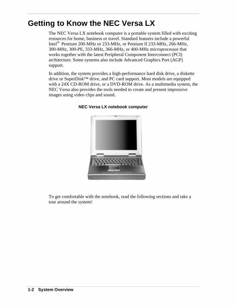
Getting to Know the NEC Versa LXThe NEC Versa LX notebook computer is a portable system filled with excitingresources for home, business or travel. Standard features include a powerfulIntel® Pentium 200-MHz or 233-MHz, or Pentium II 233-MHz, 266-MHz,300-MHz, 300-PE, 333-MHz, 366-MHz, or 400-MHz microprocessor thatworks together with the latest Peripheral Component Interconnect (PCI)architecture. Some systems also include Advanced Graphics Port (AGP)support.
In addition, the system provides a high-performance hard disk drive, a diskettedrive or SuperDisk™ drive, and PC card support. Most models are equippedwith a 24X CD-ROM drive, or a DVD-ROM drive. As a multimedia system, theNEC Versa also provides the tools needed to create and present impressiveimages using video clips and sound.
NEC Versa LX notebook computer
To get comfortable with the notebook, read the following sections and take atour around the system!

System Overview 1-3
Around the Front of the SystemThe NEC Versa is compact with features on every side. First, look at the front ofthe NEC Versa. The following sections describe front features, beginning withthe liquid crystal display (LCD) panel.
LCD Panel
The NEC Versa LX comes with a color LCD panel that can be adjusted for acomfortable viewing position. Depending on the model, the system is equippedwith a:
! 12.1-inch color Thin Film Transistor (TFT) Super Video Graphics Array(SVGA) panel.
! 13.3-inch color Thin Film Transistor (TFT) Extended Graphics Array(XGA) panel.
! 14.1-inch Thin Film Transistor (TFT) Extended Graphics Array (XGA)panel.
To adjust the LCD panel brightness:
! Use the slide switch on the front of the panel (12.1-inch TFT, SVGApanel only).
! Press the Fn-F8 and Fn-F9 function keys.
In addition to the superior display panel, the NEC Versa is equipped with aPentium II processor with AGP. AGP adds new features for graphicsaccelerators such as dedicated access to main memory and faster transfer rates.AGP further expands current 3D capabilities to new levels of visual realismproviding higher performance 3D graphics capabilities.

1-4 System Overview
Status Panel
The NEC Versa status panel provides the features shown in the figure. Thesefeatures are described after the figure.
Status panel
A – Microphone B – Operating Status LEDs
! Microphone — A strategically positioned built-in microphone allows theuser to record monophonic sound directly into the notebook computer.
! Operating Status LEDs — informs users of the NEC Versa’s currentoperating status. See the following figure and list for each icon’smeaning.
Operating status LEDs
A – IDE/VBIII Devices B – Caps Lock C – Num LockD – Scroll Lock E – File Bay
IDE/VBIII devices — lights when the NEC Versa writes data to orretrieves data from the internal hard disk drive or a device in theVersaBay III.
Caps Lock — lights when Caps Lock mode is in effect.
Num Lock — lights when Num Lock mode is active.
Scroll Lock — lights when Scroll Lock mode is in effect.
System Overview 1-5
File Bay — lights when the NEC Versa accesses either the floppydisk drive or SuperDisk drive installed in the file bay.
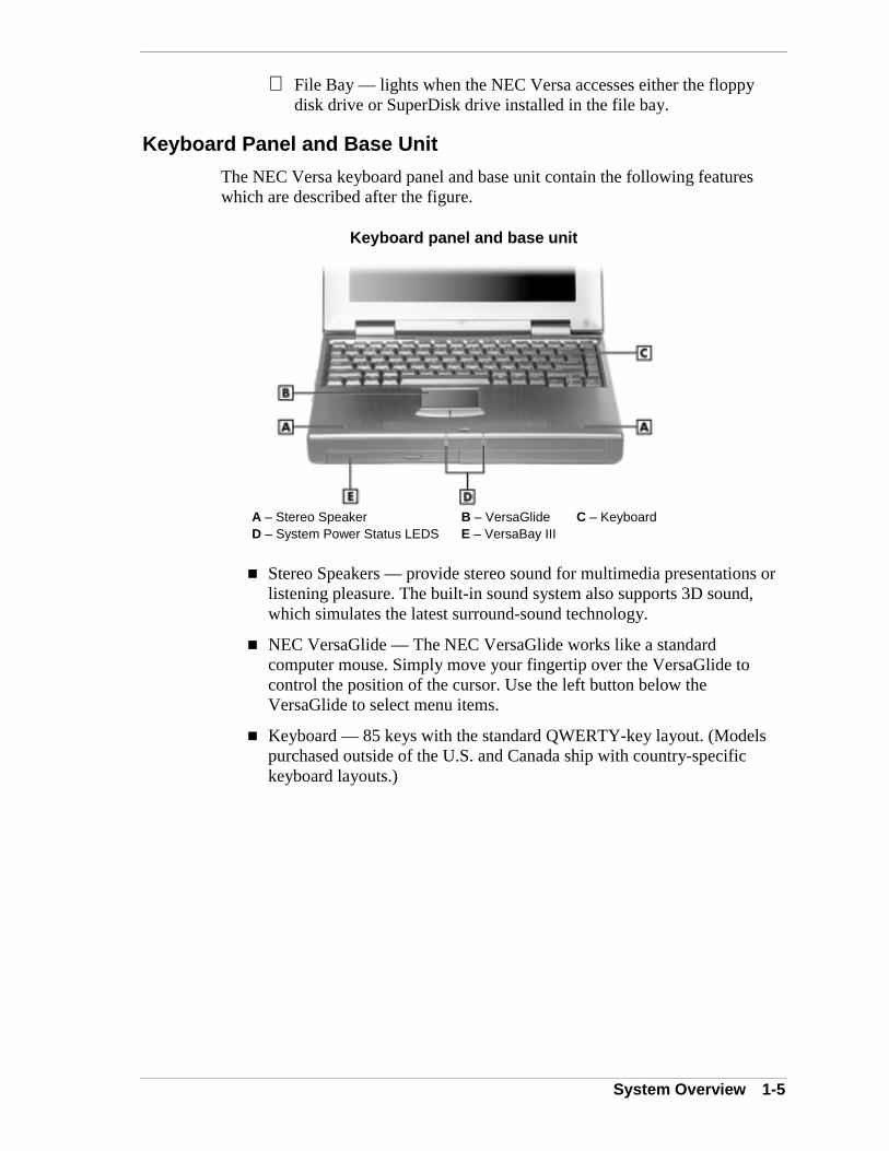
Keyboard Panel and Base Unit
The NEC Versa keyboard panel and base unit contain the following featureswhich are described after the figure.
Keyboard panel and base unit
A – Stereo Speaker B – VersaGlide C – KeyboardD – System Power Status LEDS E – VersaBay III
! Stereo Speakers — provide stereo sound for multimedia presentations orlistening pleasure. The built-in sound system also supports 3D sound,which simulates the latest surround-sound technology.
! NEC VersaGlide — The NEC VersaGlide works like a standardcomputer mouse. Simply move your fingertip over the VersaGlide tocontrol the position of the cursor. Use the left button below theVersaGlide to select menu items.
! Keyboard — 85 keys with the standard QWERTY-key layout. (Modelspurchased outside of the U.S. and Canada ship with country-specifickeyboard layouts.)
1-6 System Overview
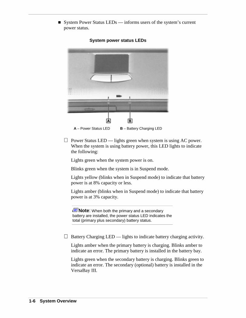
! System Power Status LEDs — informs users of the system’s currentpower status.
System power status LEDs
A – Power Status LED B – Battery Charging LED
Power Status LED — lights green when system is using AC power.When the system is using battery power, this LED lights to indicatethe following:
Lights green when the system power is on.
Blinks green when the system is in Suspend mode.
Lights yellow (blinks when in Suspend mode) to indicate that batterypower is at 8% capacity or less.
Lights amber (blinks when in Suspend mode) to indicate that batterypower is at 3% capacity.
Note: When both the primary and a secondarybattery are installed, the power status LED indicates thetotal (primary plus secondary) battery status.
Battery Charging LED — lights to indicate battery charging activity.
Lights amber when the primary battery is charging. Blinks amber toindicate an error. The primary battery is installed in the battery bay.
Lights green when the secondary battery is charging. Blinks green toindicate an error. The secondary (optional) battery is installed in theVersaBay III.

System Overview 1-7
! NEC VersaBay III™ — A 24X CD-ROM drive, a SuperDisk drive, or aDVD-ROM drive comes installed in the NEC VersaBay III on the frontof the system.
The VersaBay III accepts additional options, including an optionalSuperDisk drive, second Li-Ion battery, or an additional hard disk drive.
Around the Back of the SystemYou will find system ports for connecting optional devices (like a printer, adocking station, or an external monitor) on the back of the NEC Versa. Theseports are described after the figure.
Ports on the back of the system
A – PortBar Notch B – Serial Port C – Expansion PortD – AC Power Port E – External Monitor Port F – Parallel PortG – PS/2 Port
! PortBar Notches — Use these notches to secure the PortBar to the backof the system.
! Serial Port — Use this port to connect an external modem or other serialdevice.
! Expansion Port — This port (also called the Docking port) provides aconnection for NEC Versa LX options including the NEC Versa Dockand the NEC Versa PortBar.
CAUTIONOnly dock the NEC Versa LX system on the NEC VersaDock. The cover of the NEC Versa Dock is speciallydesigned to allow for proper system cooling.
! AC Power Port — Use the power jack to attach the NEC Versa to a DCpower source, such as the AC adapter or the optional auto adapter.
! External Monitor (Video) Port — Use this 15-pin port to attach anexternal monitor to the NEC Versa. The user can run the LCD displayand the external monitor simultaneously or run either alone.

1-8 System Overview
! Parallel Port — Use this port to connect a parallel printer or other paralleldevice. The port is an Enhanced Capabilities Port (ECP). The ECPstandard provides a greater processing speed than the conventionalparallel port. It also supports Enhanced Parallel Port (EPP),bi-directional, and uni-directional protocols.
! PS/2 Port –— Use the standard PS/2 port to connect an externalPS/2-style mouse or a PS/2-style keyboard to the system. With anoptional Y-cable adapter, the user can connect both a mouse and akeyboard at the same time.
Around the Left Side of the SystemThe left side of the NEC Versa offers the following features, which aredescribed after the figure.
Left side features
A – Fan Vents B – IR Port C – PC Card SlotsD – USB Port E – TV Out (RCA) Port F – TV Out (S-Video) Port
! Fan Vents — Allows the system to cool properly and maintain a safeoperating temperature.
CAUTIONAlways keep the fan vents clear to allow proper systemcooling.
! IR Port — Transfers files between the NEC Versa and an IR-equippeddesktop, notebook computer, or other devices.
Note: The NEC Versa LX ships with the IR portdisabled.
! PC card slots — Provides two slots for inserting two Type II PC cards orone Type III PC card.
System Overview 1-9
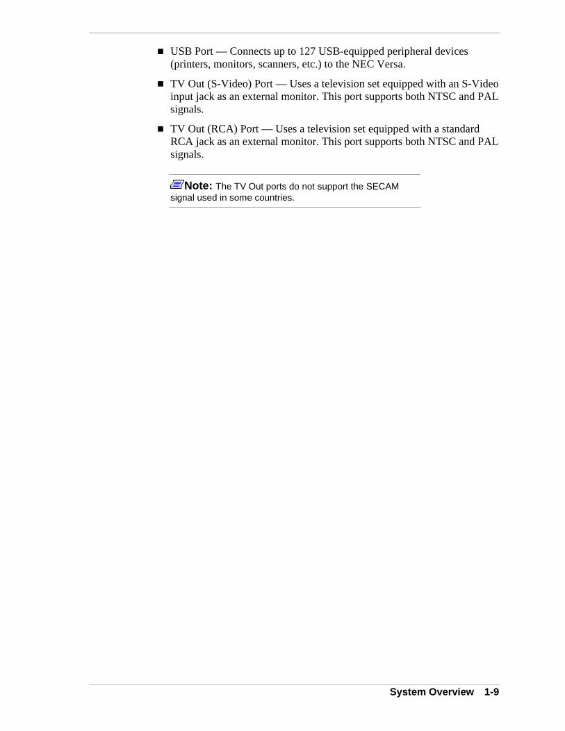
! USB Port — Connects up to 127 USB-equipped peripheral devices(printers, monitors, scanners, etc.) to the NEC Versa.
! TV Out (S-Video) Port — Uses a television set equipped with an S-Videoinput jack as an external monitor. This port supports both NTSC and PALsignals.
! TV Out (RCA) Port — Uses a television set equipped with a standardRCA jack as an external monitor. This port supports both NTSC and PALsignals.
Note: The TV Out ports do not support the SECAMsignal used in some countries.

1-10 System Overview
Around the Right Side of the SystemThe right-side of the NEC Versa offers the features shown in the followingfigure. Features are described after the figure.
Right side features
A – Headphones/Line Out B – Line In C – External MicrophoneD – Kensington Lock E – File Bay F – Power/Sleep ButtonG – Audio Volume
! Audio ports
Headphones/Line-Out — Allows the user to connect externalheadphones or speakers to the NEC Versa. Plugging in headphonesdisables the built-in system speakers.
Line-In — Uses another audio system, like a home stereo, as an inputsource. Use a cable to connect to the Line-Out port on the other audiosystem to record or play.
External Microphone (MIC) — Allows the user to connect anexternal microphone for monophonic recording or amplificationthrough the unit. Plugging in an external microphone disables thebuilt-in microphone.
! Kensington Lock — Lets the user provide added security by installing anoptional Kensington Lock.
! File Bay — The NEC Versa ships with a 3.5-inch, 1.44 MB diskette driveor the SuperDisk drive installed in the file bay.

System Overview 1-11
! Power/Sleep Button — slide the Power/Sleep button toward the front ofthe system to power on, power off, and to put the computer into Suspendmode.
Slide the Power/Sleep button toward the front of the system to poweron.
Hold the Power/Sleep button in place for 4 or fewer seconds to putthe system into Suspend mode. (Before using the Power/Sleep buttonto put the system into Suspend mode, set the System Switch BIOSparameter to the Sleep button.)
Hold the Power/Sleep button in place for more than 4 seconds toinitiate power override (powers off the system).
The Power/Sleep button is a “smart” switch, meaning that it recognizeswhen the system is in Suspend mode. If in Suspend mode, the user cannotpower off until he/she slides forward the Power/Sleep button again tobring it out of Suspend mode.
In addition, the Smart Power switch invokes an orderly shutdown in theWindows 95 and Windows NT environments. If the user uses thePower/Sleep button to turn off the system while applications are running,the Smart Power Switch alerts the operating system. The operatingsystem prompts the user to save all data and invokes an orderly shutdownprocedure.
Put the unit in Suspend mode when you need to be away from the systemfor a short period of time and want to return to where you left off.Suspend mode shuts down all devices in the system while retaining dataand system status. Use the Fn-Power/Sleep key combination to initiate amanual save-to-file. Slide the Smart Power switch (Power/Sleep button)toward the front of the system to resume from a save-to-file.
! Volume Control — Allows the user to control the speaker volume.
1-12 System Overview
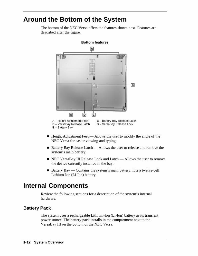
Around the Bottom of the SystemThe bottom of the NEC Versa offers the features shown next. Features aredescribed after the figure.
Bottom features
A – Height Adjustment Feet B – Battery Bay Release LatchC – VersaBay Release Latch D – VersaBay Release LockE – Battery Bay
! Height Adjustment Feet — Allows the user to modify the angle of theNEC Versa for easier viewing and typing.
! Battery Bay Release Latch — Allows the user to release and remove thesystem’s main battery.
! NEC VersaBay III Release Lock and Latch — Allows the user to removethe device currently installed in the bay.
! Battery Bay — Contains the system’s main battery. It is a twelve-cellLithium-Ion (Li-Ion) battery.
Internal ComponentsReview the following sections for a description of the system’s internalhardware.
Battery Pack
The system uses a rechargeable Lithium-Ion (Li-Ion) battery as its transientpower source. The battery pack installs in the compartment next to theVersaBay III on the bottom of the NEC Versa.
System Overview 1-13
Hard Disk Drive
A standard 2.5-inch, 9.5 mm or 12.7 mm hard disk drive ships with the system.Some of the earlier non-AGP 200-MHz, 233-MHz, and 266-MHz systems havea non-user replaceable hard disk drive.
File Bay
The NEC Versa LX ships with a 3.5-inch, 1.44 MB diskette drive or theSuperDisk drive installed in the file bay.
VersaBay III
A 24X CD-ROM drive or a DVD-ROM drive comes installed in the NECVersaBay III on the front of the system.
CPU Board
The CPU board is a rectangular-shaped board located above the main board.The CPU board is part of a subassembly, which includes a heat sink and theCPU board.
Audio Board
The audio board provides the NEC Versa system with its audio I/O capabilitiesvia a line-in jack, headphone and microphone jacks. It is situated on top of themain board.
CMOS Battery
The lithium battery (3 Volts, 30 mAH capacity) is attached to P28 on the mainboard. It provides short-term battery backup and prevents data loss in thesystem’s complementary metal-oxide semiconductor (CMOS) RAM. Thismemory area contains information on the system’s configuration like date, time,drives, and memory. The CMOS battery has a useful life of approximately threeyears.
Bridge Battery
The bridge battery saves the memory contents and system status for up to 5minutes while changing the main battery. It is connected to the main board viaconnector P5. The AC adapter maintains voltage in the bridge battery when thesystem is powered on or off. The bridge battery stores 7.2 Volts, 70 mAH.
1-14 System Overview
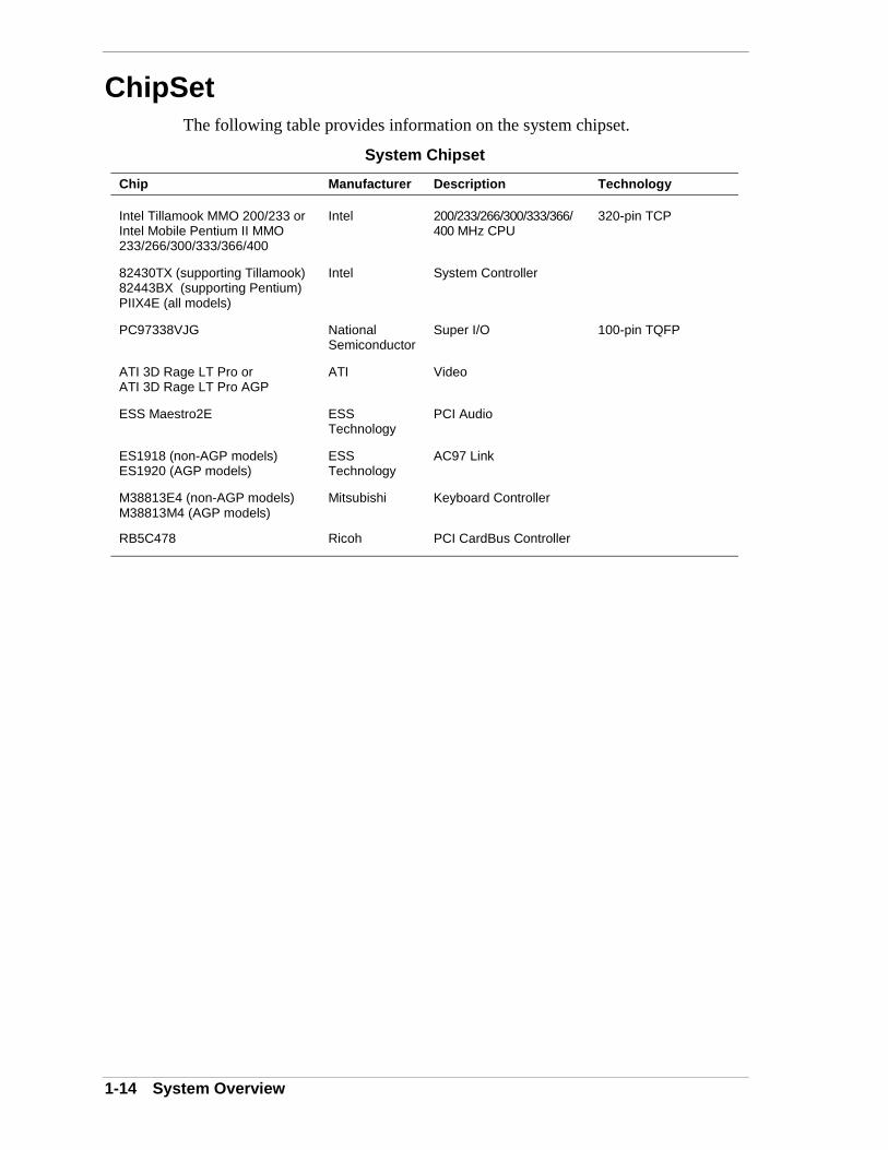
ChipSetThe following table provides information on the system chipset.
System Chipset
Chip Manufacturer Description Technology
Intel Tillamook MMO 200/233 orIntel Mobile Pentium II MMO233/266/300/333/366/400
Intel 200/233/266/300/333/366/400 MHz CPU
320-pin TCP
82430TX (supporting Tillamook)82443BX (supporting Pentium)PIIX4E (all models)
Intel System Controller
PC97338VJG NationalSemiconductor
Super I/O 100-pin TQFP
ATI 3D Rage LT Pro orATI 3D Rage LT Pro AGP
ATI Video
ESS Maestro2E ESSTechnology
PCI Audio
ES1918 (non-AGP models)ES1920 (AGP models)
ESSTechnology
AC97 Link
M38813E4 (non-AGP models)M38813M4 (AGP models)
Mitsubishi Keyboard Controller
RB5C478 Ricoh PCI CardBus Controller
2System Configuration and Setup
� Power Sources for Your NEC Versa
� BIOS Setup
� NEC CSD Utilities
� Software Applications and Drivers
2-2 System Configuration and Setup
Power Sources for Your NEC VersaThe NEC Versa can be powered using three different sources, making it a trulyportable system. Operate your NEC Versa just about anywhere using one of thefollowing power sources:
� the AC adapter connected to an electrical wall outlet (using AC power).
� the battery pack or an optional second battery pack.
� the optional Auto adapter.
Read the following sections for specific steps on powering on the system withthese power sources.
Using the AC Adapter
Use the AC adapter and power cable that came with your NEC Versa to runyour computer on alternating current (AC) power, or to recharge the batterypack. Use the AC adapter whenever a wall outlet is nearby.
Keep the adapter connected whenever possible. The AC adapter charges thebattery whether or not you are using the NEC Versa or have the system poweredon.
! WARNINGDo not attempt to disassemble the AC adapter. The ACadapter has no user-replaceable or serviceable parts inside.Dangerous voltage in the AC adapter can cause seriouspersonal injury or death. The AC adapter is intended for usewith a computer. Both must meet EN609050 standards.
System Configuration and Setup 2-3
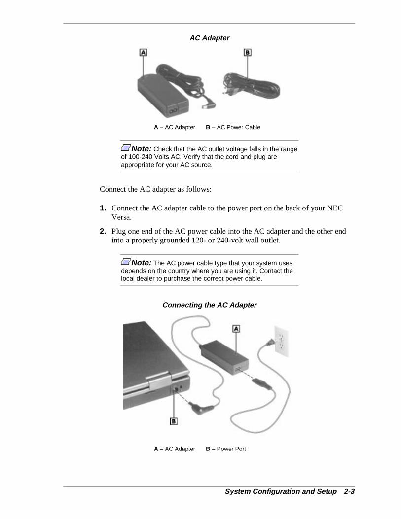
AC Adapter
A – AC Adapter B – AC Power Cable
Note: Check that the AC outlet voltage falls in the rangeof 100-240 Volts AC. Verify that the cord and plug areappropriate for your AC source.
Connect the AC adapter as follows:
1. Connect the AC adapter cable to the power port on the back of your NECVersa.
2. Plug one end of the AC power cable into the AC adapter and the other endinto a properly grounded 120- or 240-volt wall outlet.
Note: The AC power cable type that your system usesdepends on the country where you are using it. Contact thelocal dealer to purchase the correct power cable.
Connecting the AC Adapter
A – AC Adapter B – Power Port
2-4 System Configuration and Setup
! CAUTIONDo not cover or place objects on the AC adapter. Keepingthe adapter clear of objects lets the adapter cool properlyduring use.
Powering On
Power on the system as follows:
1. Locate the latch on the front of the LCD panel, slide it to the right, and raisethe panel.
2. Locate the Power/Sleep button and slide it toward the front of the system toturn on system power.
Using the Main Battery Pack
The NEC Versa comes with a rechargeable Lithium-Ion (Li-Ion) battery pack.You can run your system on battery power for approximately two to four hourswith power management features enabled. It’s easy to install and remove.
Your NEC Versa system provides tools to help you keep track of the main (oran optional) battery’s power level. These include the power status LEDdescribed in Chapter 1, and SystemSoft’s PowerProfiler™ (for Window NTsystems, only) described later in this chapter. Both provide important batterystatus information.
When battery power is very low, the power LED flashes amber.
When battery power gets low, do one of the following:
� Slide the Power/Sleep button toward the front of the system and hold it inplace for 4 or fewer seconds to put your system in Suspend mode. (Beforeusing the Power/Sleep button to put the system into Suspend mode set theSystem Switch BIOS parameter to Sleep button.) Remove the battery packand replace it with a fully charged battery.
� Suspend in Windows 95 from the Start menu.
� Leave the battery pack in the system and connect your NEC Versa to theAC adapter and a wall outlet. If you connect the system to AC power andkeep the system within standard operating temperatures, the batteryrecharges in approximately 2–3 hours whether or not you use yoursystem.
You can also buy an optional NEC Versa battery charger to charge your battery.See the NEC CSD web site at http://www.nec-computers.com/.
System Configuration and Setup 2-5
! WARNINGTo prevent accidental battery ignition or explosion, adhere tothe following:
� Keep the battery away from extreme heat.
� Keep metal objects away from the battery terminals toprevent a short circuit.
� Make sure the battery is properly installed in the batterybay.
� Read the precautions printed on the battery later in thischapter.
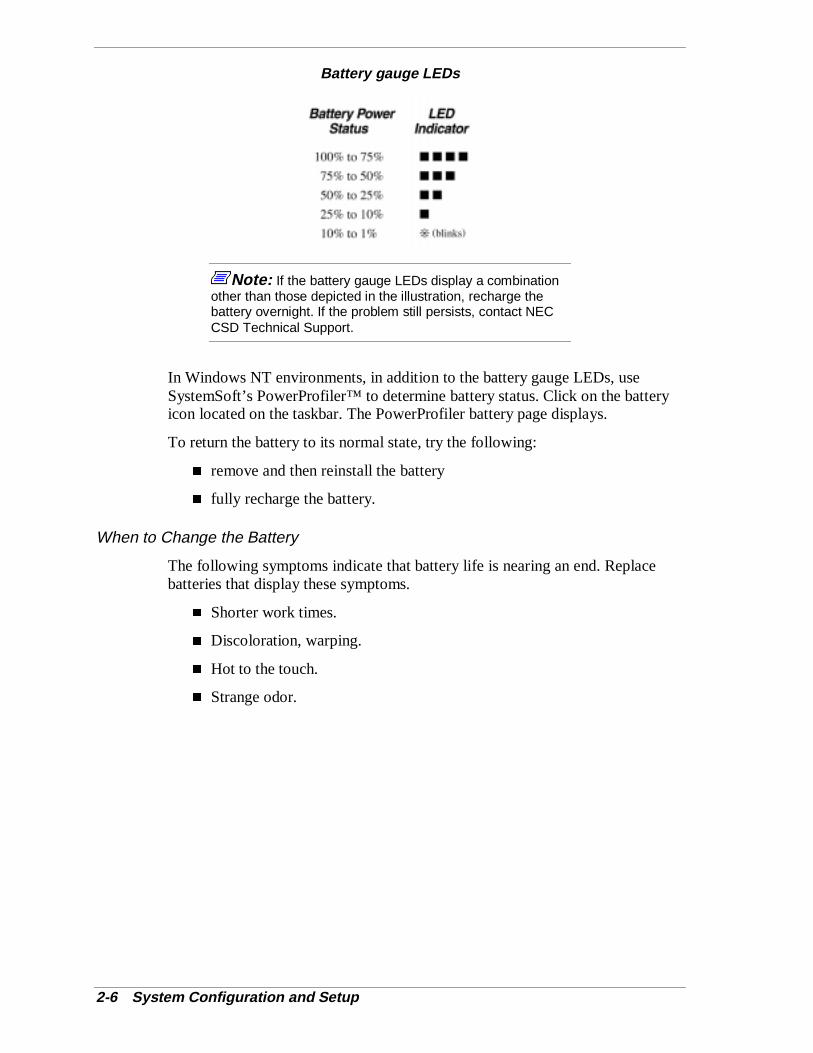
Determining Battery Status
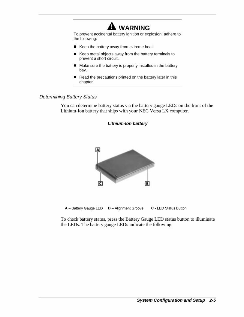
You can determine battery status via the battery gauge LEDs on the front of theLithium-Ion battery that ships with your NEC Versa LX computer.
Lithium-Ion battery
A – Battery Gauge LED B – Alignment Groove C - LED Status Button
To check battery status, press the Battery Gauge LED status button to illuminatethe LEDs. The battery gauge LEDs indicate the following:
2-6 System Configuration and Setup
Battery gauge LEDs
Note: If the battery gauge LEDs display a combinationother than those depicted in the illustration, recharge thebattery overnight. If the problem still persists, contact NECCSD Technical Support.
In Windows NT environments, in addition to the battery gauge LEDs, useSystemSoft’s PowerProfiler™ to determine battery status. Click on the batteryicon located on the taskbar. The PowerProfiler battery page displays.
To return the battery to its normal state, try the following:
� remove and then reinstall the battery
� fully recharge the battery.
When to Change the Battery
The following symptoms indicate that battery life is nearing an end. Replacebatteries that display these symptoms.
� Shorter work times.
� Discoloration, warping.
� Hot to the touch.
� Strange odor.
System Configuration and Setup 2-7
Battery Handling
Keep the following in mind when removing or replacing a battery.
� Use only the battery designed for your system in the NEC Versa. Mixingother manufacturer’s batteries, or using a combination of very old andnew batteries can deteriorate battery and equipment performance.
� Turn off power to the system after use. Keeping system power on candegrade battery performance and shorten battery life.
� Clean the battery terminals with a dry cloth when they get dirty.
� Keep the battery out of the reach of children.
Replacing the Battery
Replace the battery pack installed in your NEC Versa system as follows.
Note: Use the batteries in the NEC Versa computer forwhich they are designed. Also, installing anothermanufacturer’s battery, or using a combination of very oldand new batteries can deteriorate battery and equipmentperformance.
1. Save your files, exit Windows, and put your system into Suspend mode orturn off system power.
2. Close the LCD and turn the system over.
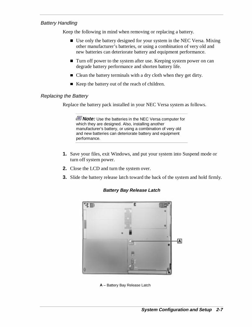
3. Slide the battery release latch toward the back of the system and hold firmly.
Battery Bay Release Latch
A – Battery Bay Release Latch
2-8 System Configuration and Setup
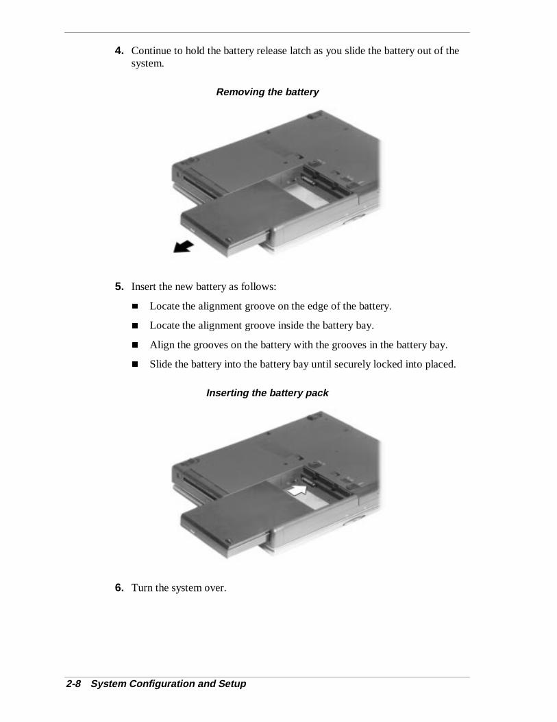
4. Continue to hold the battery release latch as you slide the battery out of thesystem.
Removing the battery
5. Insert the new battery as follows:
� Locate the alignment groove on the edge of the battery.
� Locate the alignment groove inside the battery bay.
� Align the grooves on the battery with the grooves in the battery bay.
� Slide the battery into the battery bay until securely locked into placed.
Inserting the battery pack
6. Turn the system over.
System Configuration and Setup 2-9
Battery Precautions
To prevent accidental battery ignition, rupture, or explosion, adhere to thefollowing precautions.
! WARNINGThere is a danger of explosion if the battery is incorrectlyreplaced. Replace only with the same or equivalent typerecommended by the manufacturer. Discard used batteriesaccording to the manufacturer’s instructions.
To avoid personal injury and property damage, read thesebattery precautions on handling, charging, and disposingLi-Ion batteries.
� Keep the battery away from heat sources including directsunlight, open fires, microwave ovens, and high-voltagecontainers. Temperatures over 140º F (60ºC) may causedamage.
� Do not drop or impact the battery.
� Do not disassemble the battery.
� Do not solder the battery.
� Do not puncture the battery.
� Do not use a battery that appears damaged or deformed,has any rust on its casing, is discolored, overheats, oremits a foul odor.
� Keep the battery dry and away from water.
� Keep metal objects away from battery terminals. Metalobjects in contact with the terminals can cause a shortcircuit and damage.
� If the battery leaks:
If the battery leaks onto skin or clothing, wash the areaimmediately with clean water. Battery fluid can cause askin rash and damage fabric.
If battery fluid gets into eyes, DO NOT rub; rinse withclear water immediately for at least 15 minutes andconsult a doctor.
Take extra precautions to keep a leaking battery awayfrom fire. There is a danger of ignition or explosion.

2-10 System Configuration and Setup
Recharging Battery Precautions
Adhere to the following precautions when recharging the primary or secondarybattery.
� Use only the NEC battery charger designed for your NEC Versa batterytype. Different NEC Versa models require different batteries and batterychargers.
� Charge the battery for the specified charge time only.
� During charging, keep the environmental temperature between 32°F and104°F (5°C to 35°C).
� Read the instructions that came with the battery charger before chargingthe battery.
Extending Battery Life
While on the road, it is important to be aware of the simple things you can do toextend the life of the system’s main battery. One way is to keep the brightnesssetting on the panel low. Use the slide switch on the front of the panel(12.1-inch TFT, SVGA panel only) or use the Fn+F8 and Fn+F9 function keys tocontrol the brightness.
NEC VersaBay III Battery
The NEC VersaBay III battery provides an optional second Lithium-Ion (Li-Ion)battery to use in your NEC Versa LX computer. Inserting a second fully chargedbattery increases battery life to approximately 4 to 5 hours.
See the NEC CSD web site at http://www.nec-computers.com/ for details aboutthe NEC VersaBay III battery.
Internal Batteries
The twelve-cell Lithium-Ion (Li-Ion) battery provides the main power source inyour NEC Versa LX computer. See Chapter 9 for a list of battery specifications.In addition to this battery, the CMOS battery and bridge battery also providesystem power.
CMOS Battery
This lithium battery provides battery backup and prevents data loss in thesystem’s complementary metal-oxide semiconductor (CMOS) RAM. Thismemory area contains information on the system’s configuration, for exampledate, time, drives, and memory. The CMOS battery may discharge completely ifthe NEC Versa notebook remains unused for approximately two months.
System Configuration and Setup 2-11
Bridge Battery
The bridge battery saves your system status in Suspend mode for up to fiveminutes. This gives you time to install a fully charged battery or plug in ACpower when your battery charge becomes low.
Only an authorized NEC CSD technician can change a bridge battery.
! CAUTIONConnect your NEC Versa system to AC power for a full 24hours before using it on battery power for the first time.Doing so insures that the bridge battery is fully charged andthat no data is lost during a battery change.
BIOS SetupYour NEC Versa LX computer comes with a hardware program called BIOSSetup that allows you to view and set system parameters. BIOS setup alsoallows you to set password features that protect your system from unauthorizeduse.
Use BIOS setup to:
� set the current time and date
� customize your operating system to reflect your computer hardware
� secure your system with a password
� balance your performance needs with power conservation.
How to Enter the BIOS Setup
Access the BIOS utility at power-on. Just press F2 when a prompt similar to thefollowing appears.
Press <F2> to enter Setup.
When you press F2 to enter BIOS Setup, the system interrupts the Power-OnSelf-Test (POST) and displays the current CMOS RAM settings.
Note: To pause the POST, press and hold down INS.To view POST messages, press and hold down ESC whenprompted.
If the system detects an error during POST, it prompts you with a double beepand a message: “Press <F1> to resume.” If you press F1, the system entersBIOS Setup automatically. If you want to fix the error, carefully read the errormessage that appears above the prompt (taking notes if you want), and press F2.
2-12 System Configuration and Setup
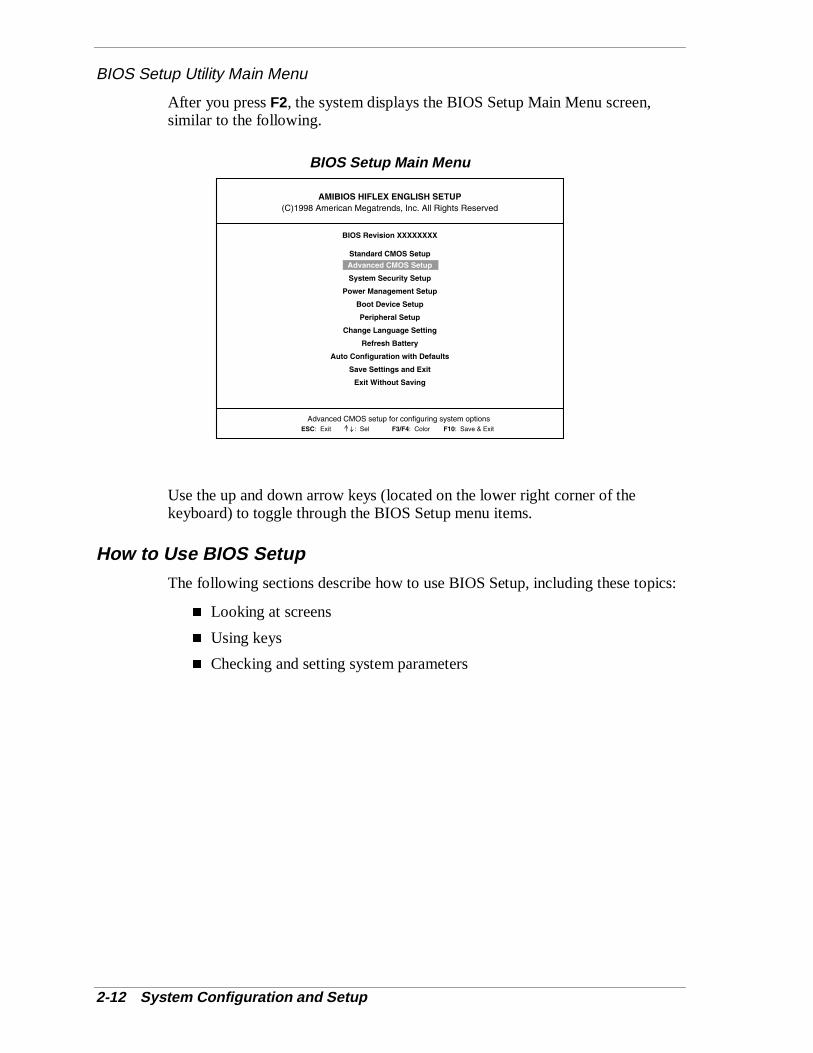
BIOS Setup Utility Main Menu
After you press F2, the system displays the BIOS Setup Main Menu screen,similar to the following.
BIOS Setup Main Menu
Use the up and down arrow keys (located on the lower right corner of thekeyboard) to toggle through the BIOS Setup menu items.
How to Use BIOS SetupThe following sections describe how to use BIOS Setup, including these topics:
� Looking at screens
� Using keys
� Checking and setting system parameters
System Configuration and Setup 2-13
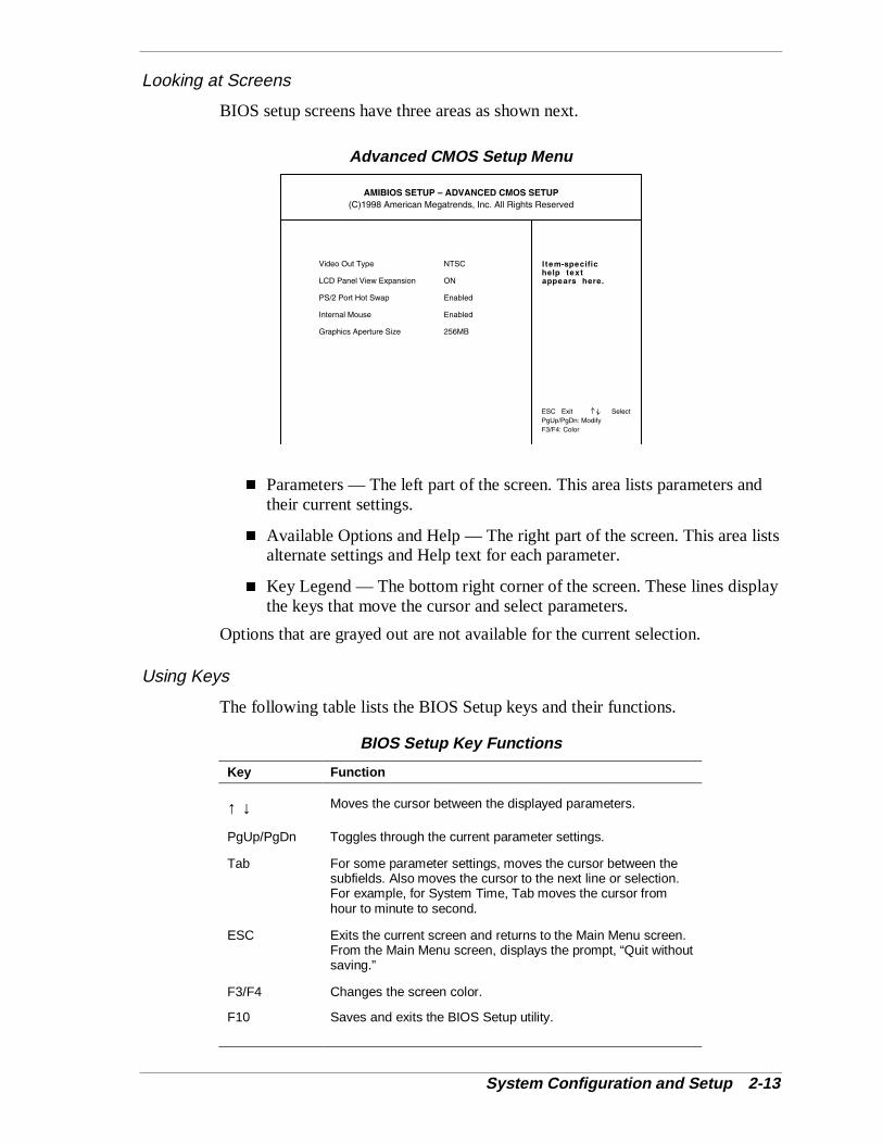
Looking at Screens
BIOS setup screens have three areas as shown next.
Advanced CMOS Setup Menu
� Parameters — The left part of the screen. This area lists parameters andtheir current settings.
� Available Options and Help — The right part of the screen. This area listsalternate settings and Help text for each parameter.
� Key Legend — The bottom right corner of the screen. These lines displaythe keys that move the cursor and select parameters.
Options that are grayed out are not available for the current selection.
Using Keys
The following table lists the BIOS Setup keys and their functions.
BIOS Setup Key Functions
Key Function
↑ ↓ Moves the cursor between the displayed parameters.
PgUp/PgDn Toggles through the current parameter settings.
Tab For some parameter settings, moves the cursor between thesubfields. Also moves the cursor to the next line or selection.For example, for System Time, Tab moves the cursor fromhour to minute to second.
ESC Exits the current screen and returns to the Main Menu screen.From the Main Menu screen, displays the prompt, “Quit withoutsaving.”
F3/F4 Changes the screen color.
F10 Saves and exits the BIOS Setup utility.
2-14 System Configuration and Setup
Checking/Setting System Parameters
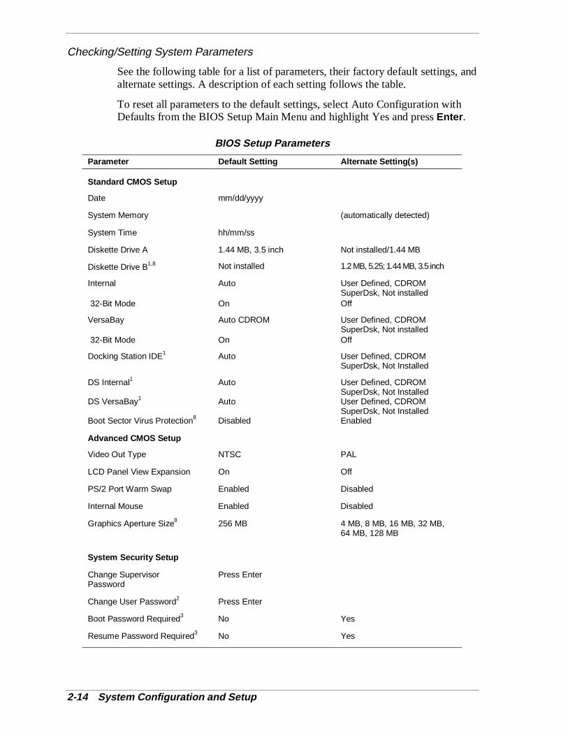
See the following table for a list of parameters, their factory default settings, andalternate settings. A description of each setting follows the table.
To reset all parameters to the default settings, select Auto Configuration withDefaults from the BIOS Setup Main Menu and highlight Yes and press Enter .
BIOS Setup Parameters
Parameter Default Setting Alternate Setting(s)
Standard CMOS Setup
Date mm/dd/yyyy
System Memory (automatically detected)
System Time hh/mm/ss
Diskette Drive A 1.44 MB, 3.5 inch Not installed/1.44 MB
Diskette Drive B1,8 Not installed 1.2 MB, 5.25; 1.44 MB, 3.5 inch
Internal Auto User Defined, CDROMSuperDsk, Not installed
32-Bit Mode On Off
VersaBay Auto CDROM User Defined, CDROMSuperDsk, Not installed
32-Bit Mode On Off
Docking Station IDE1 Auto User Defined, CDROMSuperDsk, Not Installed
DS Internal1 Auto User Defined, CDROMSuperDsk, Not Installed
DS VersaBay1 Auto User Defined, CDROMSuperDsk, Not Installed
Boot Sector Virus Protection8 Disabled Enabled
Advanced CMOS Setup
Video Out Type NTSC PAL
LCD Panel View Expansion On Off
PS/2 Port Warm Swap Enabled Disabled
Internal Mouse Enabled Disabled
Graphics Aperture Size8 256 MB 4 MB, 8 MB, 16 MB, 32 MB,64 MB, 128 MB
System Security Setup
Change SupervisorPassword
Press Enter
Change User Password2 Press Enter
Boot Password Required3 No Yes
Resume Password Required3 No Yes
System Configuration and Setup 2-15
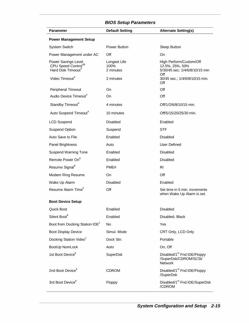
BIOS Setup Parameters
Parameter Default Setting Alternate Setting(s)
Power Management Setup
System Switch Power Button Sleep Button
Power Management under AC Off On
Power Savings Level Longest Life High Perform/Custom/Off CPU Speed Control48 100% 12.5%, 25%, 50% Hard Disk Timeout4 2 minutes 5/30/45 sec; 1/4/6/8/10/15 min
Off Video Timeout4 2 minutes 30/45 sec.; 1/4/6/8/10/15 min.
Off
Peripheral Timeout On Off
Audio Device Timeout4 On Off
Standby Timeout4 4 minutes Off/1/2/6/8/10/15 min.
Auto Suspend Timeout4 10 minutes Off/5/15/20/25/30 min.
LCD Suspend Disabled Enabled
Suspend Option Suspend STF
Auto Save to File Enabled Disabled
Panel Brightness Auto User Defined
Suspend Warning Tone Enabled Disabled
Remote Power On8 Enabled Disabled
Resume Signal8 PME# RI
Modem Ring Resume On Off
Wake Up Alarm Disabled Enabled
Resume Alarm Time5 Off Set time in 5 min. incrementswhen Wake Up Alarm is set.
Boot Device Setup
Quick Boot Enabled Disabled
Silent Boot8 Enabled Disabled, Black
Boot from Docking Station IDE1 No Yes
Boot Display Device Simul. Mode CRT Only, LCD Only
Docking Station Video1 Dock Stn. Portable
BootUp NumLock Auto On, Off
1st Boot Device6 SuperDsk Disabled/1st Fnd IDE/Floppy/SuperDsk/CDROM/SCSI/Network
2nd Boot Device6 CDROM Disabled/1st Fnd IDE/Floppy/SuperDsk
3rd Boot Device6 Floppy Disabled/1st Fnd IDE/SuperDsk/CDROM
2-16 System Configuration and Setup
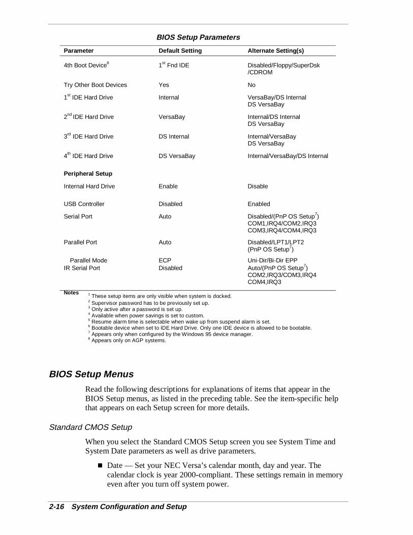
BIOS Setup Parameters
Parameter Default Setting Alternate Setting(s)
4th Boot Device6 1st Fnd IDE Disabled/Floppy/SuperDsk/CDROM
Try Other Boot Devices Yes No
1st IDE Hard Drive Internal VersaBay/DS InternalDS VersaBay
2nd IDE Hard Drive VersaBay Internal/DS InternalDS VersaBay
3rd IDE Hard Drive DS Internal Internal/VersaBayDS VersaBay
4th IDE Hard Drive DS VersaBay Internal/VersaBay/DS Internal
Peripheral Setup
Internal Hard Drive Enable Disable
USB Controller Disabled Enabled
Serial Port Auto Disabled/(PnP OS Setup7)COM1,IRQ4/COM2,IRQ3COM3,IRQ4/COM4,IRQ3
Parallel Port Auto Disabled/LPT1/LPT2(PnP OS Setup7)
Parallel Mode ECP Uni-Dir/Bi-Dir EPPIR Serial Port Disabled Auto/(PnP OS Setup7)
COM2,IRQ3/COM3,IRQ4COM4,IRQ3
Notes 1 These setup items are only visible when system is docked.
2 Supervisor password has to be previously set up.3 Only active after a password is set up.4 Available when power savings is set to custom.5 Resume alarm time is selectable when wake up from suspend alarm is set.6 Bootable device when set to IDE Hard Drive. Only one IDE device is allowed to be bootable.7 Appears only when configured by the Windows 95 device manager.8 Appears only on AGP systems.
BIOS Setup Menus
Read the following descriptions for explanations of items that appear in theBIOS Setup menus, as listed in the preceding table. See the item-specific helpthat appears on each Setup screen for more details.
Standard CMOS Setup
When you select the Standard CMOS Setup screen you see System Time andSystem Date parameters as well as drive parameters.
� Date — Set your NEC Versa’s calendar month, day and year. Thecalendar clock is year 2000-compliant. These settings remain in memoryeven after you turn off system power.
System Configuration and Setup 2-17
To set the date, use the Tab or arrow keys to move from field to field. Usethe PgUp or PgDn key to change the numbers within each field.
� System Memory — Displays the amount of system memory currentlyinstalled in your system.
� Time — Set the time, enter the current hour, minute, and second inhr/min/sec, 24-hour format.
To set the time use the Tab or arrow keys to move from field to field. Usethe PgUp or PgDn key to change the numbers within each field.
� Diskette Drives — Lets you designate the drive type for your diskettedrives.
� Internal Drives — Allows you to assign devices to the internal drive(s),file bay and VersaBay, in your system.
� Docking Station Drives — Enables and disables the drives installed in adocking station. (These options are only available when the NEC Versa isdocked.)
� Boot Sector Virus Protection — Write protects the boot sector of the harddisk drive to avoid infection by some virus types.
Advanced CMOS Setup
Advanced CMOS settings let you define the following functions.
� Video Out Type — Specifies the signal type used by the video deviceconnected to the TV Out Port.
� LCD Panel View Expansion — Specifies whether the panel view isreduced/off or expanded/on.
� PS/2 Port Warm Swap — Specifies whether or not you can swap a PS/2device during system operation.
� Internal Mouse — Specifies whether or not you can use both the internaland the external mouse.
� Graphics Aperture Size — Sets the graphics aperture size used by theAGP video device.
System Security Setup
� Change Supervisor Password — Allows you to establish passwordprotection for entering the BIOS setup utility, booting the system, andresuming from Suspend mode.
� Change User Password — Allows you to establish a user password oncea Supervisor password is set.
� Boot Password Required — Indicates whether or not a password isrequired during system boot.
2-18 System Configuration and Setup
� Resume Password required — Indicates whether or not a password isrequired during system resume. Boot Password must be defined toactivate this parameter.
Power Management Setup
Your NEC Versa Windows 98 system uses the Advanced Configuration andPower Interface (ACPI) which enables the operating system to manage thepower given to each attached device and to turn off a device when not in use. Inaddition, ACPI enables manufacturers to develop computers that automaticallypower up with a touch to the keyboard.
The Power Management Setup menu lets you balance high performance andenergy conservation using parameters including the following.
� System Switch — Lets you use the Power/Sleep button as a Power switchor a sleep button.
� Power Management Under AC — Specifies whether to enable powermanagement features when AC power is in use. When AC power isconnected to your NEC Versa system, power management is usuallydisabled. If you enable this parameter, the system automatically activatesthe power management profile you set, even when AC power is used.
� Power Savings Level — Lets you choose one of four levels of powermanagement.
High Performance provides the greatest system performance withonly minimal power conservation.
Longest Life provides the maximum amount of power savings.
Off disables power management and all device timeouts.
Custom lets you define your own power management configurationby selecting values for specific device timeouts. Custom lets you setthe following timeouts.
CPU Speed Control — Allows you to set CPU performance at one offour levels.
Hard Disk Timeout — Allows you to select the amount of time beforeyour hard disk powers down.
Video Timeout — Allows you to select the amount of time beforeyour video powers off.
Peripheral Timeout — Lets you choose on/off for peripheral powermanagement.
Audio Device Timeout — Allows you to select the amount of timebefore your audio device powers off.
System Configuration and Setup 2-19
Standby Timeout — Allows you to select the system standby timeoutperiod.
Auto Suspend Timeout — Defines how much time elapses from thetime the system enters Standby mode to the time the systemautomatically enters Suspend Mode.
� LCD Suspend/Resume — Allows you to suspend/resume when the LCDpanel is opened and closed.
� Suspend Option — Allows you to specify either Suspend or Save to File(STF) as the default power management mode. In Suspend, after aspecified amount of inactivity, your NEC Versa shuts down all devices asyou specified in Power Management Setup or applies default timeouts.All your data is automatically recovered from where you left off whenyou Resume.
� Automatic STF — After 30 minutes in Suspend mode, the current file isautomatically saved to a special file on the hard disk and the system shutsdown. To resume, you must press the power button. The system reads thesaved file and sets up your system accordingly.
The save-to-file area is present on your hard drive, pressing theFn-Power/Sleep key combination puts the system into Save to File mode.(Before using the Power/Sleep button to put the system into Suspendmode set the System Switch BIOS parameter to Sleep button.) For detailsabout creating the save-to-file area, see the section later in this chapter,“HDPREPEZ Utility.”
� Panel Brightness — Lets you select the LCD screen brightness.
� Suspend Warning Tone — Specifies whether the system warning tonesounds when Suspend mode starts. It is best to keep this option enabled.
� Remote Power On — Lets you choose whether the system resumesautomatically when an external serial modem receives a ring signal.
� Resume Signal — Lets you select the signal that generates a modem ringresume.
� Modem Ring Resume — Lets you choose whether the system resumesautomatically when an internal serial modem receives a ring signal.
� Wake Up from Suspend Alarm/Resume Alarm Time — Lets you set aresume time from Suspend mode.
Boot Device Setup
Boot Device Setup allows you to define the following functions.
� Quick Boot — Specifies whether or not the system performs all testsduring system boot.
2-20 System Configuration and Setup
� Silent Boot — Specifies whether or not to display the NEC logo duringsystem boot.
� Boot from Docking Station IDE — Specifies whether or not the systemboots from the docking station IDE device. (Only when the NEC Versa isdocked.)
� Boot Display Device — Specifies the display device(s) to show thesystem boot messages on.
� Docking Station Video — Selects whether or not a video card installed inthe Docking Station is enabled at system boot.
� BootUp NumLock — Specifies whether NumLock is On or Off at systemstartup.
� Boot Devices — Specifies the sequence of boot devices and whether ornot the system attempts to boot from a device other than those specified.
� Other Boot Devices — Allows you to specify IDE devices as bootabledevices.
Peripheral Setup
The Peripheral Setup menu displays the connection locations between thesystem and the Input/Output (I/O) ports. This menu also lets you specifydifferent port assignments as needed.
Note: If you disable a device in Peripheral Setup, youcannot enable or assign it using the Windows 95 devicemanager. The device is not listed in the Windows 95 devicelist. To control the device using the Windows 95 devicemanager, select any setting other than Disable in PeripheralSetup.
� Internal Hard Drive — Allows you to enable or disable the internal harddrive.
� USB Controller — Allows you to enable or disable the USB controller.
� Serial Port — Allows you to disable the port or change its addressassignment.
� Parallel Port/Parallel Mode — Lets you disable or reassign the parallelport and select a parallel port mode.
� IR Serial Port — Allows you to enable, disable or reassign the IR serialport.
System Configuration and Setup 2-21
Other BIOS Setup Options
BIOS Setup offers other options, including the following:
� Change Language Setting — Controls the BIOS setup language display.English and Japanese are the available options on AGP models.
� Refresh Battery — Allows you to launch the Battery Refresh utility onAGP models. Once launched, the utility fully discharges your battery toeliminate any residual memory effect. Once refreshed, your battery isconditioned to recharge to its full capacity. This process may take up totwo hours to complete.
� Auto Configuration with Defaults — Loads default settings.
� Save Settings and Exit — Accepts changes made to current settings,saves to CMOS, and exits BIOS Setup.
� Exit Without Saving — Reverts to previously selected settings and exitsSetup.
Password Protection
Your NEC Versa supports a password for system security on several levels.Once you set a supervisor password, you must enter it before you can enterBIOS Setup, access the system at startup, or resume from Suspend, dependingon your configuration selection.
Your system is not protected until you set a user password and you are notprompted to enter a user password until you set a supervisor password.
Note: You must set the supervisor password before theBIOS Setup utility allows you to set a user password.
Using BIOS Setup to Set Power Management
Power Management Setup allows you to use the factory-defined power savingslevel (Longest Life), or choose between High Performance, Custom, or Off.Each provides a special value to your current work effort. These powermanagement levels were designed with you in mind. For example, you can usethem under the following circumstances:
� Longest Life — Provides the best battery life and good performance. Usewhile traveling long distances.
� High Performance — Provides the best performance and good batterylife. Use while on the road or traveling short distances.
� Custom — Lets you decide! Set power management levels according toyour own needs and present environment.
� Off — Works well in an office environment while powering your NECVersa with AC power.

2-22 System Configuration and Setup
Using the Save to File (STF) Feature
STF protects the integrity of your working files. For example, if you are calledaway from your NEC Versa and Suspend mode is selected with auto Save toFile active, your system automatically goes into Suspend mode. After 30minutes, if you don’t return, your working environment is saved to a special fileon your hard disk.
Using STF can benefit you in the following ways.
� When in STF, there is minimum battery drain.
� Preserves the life of your NEC Versa.
� Saves you time. When you return from that urgent call or meeting, youdon’t have to reboot, just press the Power/Sleep button to resume systemoperation.
To configure your NEC Versa’s STF feature follow these steps:
1. Access the BIOS setup utility.
2. Select Power Management from the Setup Main Menu.
3. Move the cursor down and highlight Suspend Option.
4. Press the PgUp key and select STF.
5. Save the settings and exit BIOS Setup.
There are three ways to invoke the NEC Versa’s STF feature, one automatic andtwo manual.
� After 30 minutes of inactivity, your NEC Versa automatically invokesSTF.
� You can manually invoke STF by:
pressing Fn Power/Sleep simultaneously, before you leave yourNEC Versa.
Selecting Start, Suspend.
Note: When the status bar indicates that there is only3% power remaining in the system, the NEC Versaautomatically performs a Save to File.
Updating the BIOS
Use the BIOS Update Diskette to update your NEC Versa system BIOS.Specifically, the BIOS is the code transmitted onto your system’smicroprocessor, or central processing unit (CPU).
System Configuration and Setup 2-23
Note: You only need to update the BIOS ifNEC CSD makes significant improvements or fixes to thecurrent system BIOS. Your authorizedNEC CSD dealer or NEC CSD Support Servicesrepresentative can help you determine this.
If you are informed that the default BIOS needs an upgrade, contact the VersaLaptop Fulfillment Hotline at (800) 842-6446, or NEC CSD Support Services at(800) 632-4525, Fax (801) 981-3133 or access the web site,www.nec-computers.com to download the most current BIOS update software.
Note: If you purchased and are using this computeroutside the U.S. or Canada, please contact a local NECCSD office or dealer in your country.
Reference the booklet, "Getting Service and Support in Asia,Australia, and Europe," to find out how to contact the localoffice in your country.
Only use the BIOS upgrade diskette for your specific model and be sure toprepare the diskette before upgrading the BIOS.
Preparing the BIOS Upgrade Diskette
Before using the BIOS upgrade diskette you must make the diskette BIOS flashready. Refer to the readme.txt file on the diskette before using the diskette.
Follow these instructions to prepare the BIOS Upgrade diskette.
1. Scan your hard drive for any computer viruses.
2. Enable the diskette for write access.
3. Insert the diskette into the file bay drive.
4. Type a:install or b:install (depending upon the hardware configuration) atthe DOS prompt and follow the on-screen instructions.
Install.bat copies the DOS system files from your hard drive onto the BIOSUpgrade diskette to make it BIOS flash ready.
The system prompts you when the process is complete.
5. Scan the BIOS Upgrade diskette for computer viruses.
The diskette is ready for use.
6. Follow the instructions for performing the BIOS update.
2-24 System Configuration and Setup
Changing the Switch Settings
Before performing the BIOS update, be sure to change the switch settings toenable BIOS flash on AGP models. Set switch 5 to “ON” before performing theBIOS update. For details about setting the switches, see “Switch Settings” inChapter 3.
Performing the BIOS Update
Use the following procedure to perform the actual BIOS update.
1. Make sure that the computer is operating under AC power, and that thepower is off. Insert the BIOS Update diskette into the file bay drive.
2. Power on the computer with the diskette in the file bay drive. The computerboots and automatically loads the utility. A message similar to the followingappears:
The NEC BIOS Update Utility should not be used to modify the BIOS in a Versa systemwhich is docked. If your Versa is docked, please exit the BIOS Update Utility, power down,and undock your Versa before running the utility. Plug in your AC cable before restarting theflash utility.
3. Press Enter to continue.
The utility checks the currently installed BIOS version and the diskette’sBIOS version. The Main menu appears.
4. Use the arrow keys to highlight the “Display BIOS Version” option on theMain menu. Use this option to check the currently installed BIOS versionand the version of the new replacement BIOS.
Press any key to return to the Main menu.
5. Highlight the “Install New BIOS” option and press Enter .
6. Press Y and then press Enter . After a brief pause, a message appears tellingyou to remove the diskette in the file bay drive.
7. Remove the diskette and press any key to continue. The utility updates theBIOS.
Power off your computer. The next time you power on your computer, youwill have the latest NEC Versa LX computer BIOS revision level.
8. Enter Setup to restore the default parameter settings.
9. Be sure to modify any custom settings that you may have configured.
10. On AGP models, be sure to change switch 5 back to “OFF” after completingthe BIOS update. For details about setting the switches, see “SwitchSettings” in Chapter 3.

System Configuration and Setup 2-25
NEC CSD UtilitiesNEC CSD provides several programs and routines designed to make your NECVersa run more efficiently.
The NEC CSD utilities include:
� NEC Customize Utility
� HDPREPEZ Utility
NEC Customize Utility
In Windows 95 systems and Windows NT systems, the NEC Customize utilitygives you the option to install or launch:
� NEC CSD custom wallpaper — installs wallpaper displaying the NEClogo.
� Application and Driver CD — installs software applications, drivers,online documents, etc.
� NEC VersaBay Swapping Utility (Windows 95 only) — takes advantageof warm swapping your VersaBay devices.
� IR setup utility to enable the IR port (Windows 95 only) — enables theIR port.
� NEC-supplied mouse driver (Windows NT only) — use this option totake advantages of the VersaGlide features.
The NEC Customize Utility screen consists of the following.
� A window at the top half of the screen lists the available options.
� The window below the options list displays a description of each optionwhen the option is highlighted.
� The Launch button initiates a selected option when clicked.
� The More Info button provides an overview of the NEC CustomizeUtility.
� The Exit button closes the NEC Customize Utility.
Using the NEC Customize Utility
Follow these steps to use the NEC Customize utility.
1. Double click the NEC Customize icon.
2. From the display window, select the desired option.
3. Click Launch to initiate the selected option.
2-26 System Configuration and Setup
4. Follow the on-screen instructions to process the selected option.
For some of the selected options you are prompted to reboot your system.
5. If necessary, click Exit to close the NEC Customize dialog box.
HDPREPEZ Utility
Using the HDPREPEZ utility automatically configures your NEC Versa’ssystem’s save-to-file (STF) area on the hard disk drive.
Note: For more details about the HDPREPEZ utility,see the HDPREPEZ.TXT file in the C:\NECUTILS\HDPREPdirectory.
Using HDPREPEZ in Windows 95 and Windows 98
In Windows 95 and Windows 98, run the HDPREPEZ utility if you increase thememory capacity in your NEC Versa beyond the factory installed base memory.
Follow these steps to run the HDPREPEZ utility.
1. Power off and restart your NEC Versa.
2. At the statement “Starting Windows 9x,” press F8.
3. From the Startup menu, select “Safe Mode Command Prompt Only,” usuallyOption 6.
4. Enter MS-DOS. At the c: prompt, type cd \necutils\hdprep and press Enterto change to the \necutils\hdprep directory.
5. Type HDPREPEZ and press Enter . The utility automatically prepares yourNEC Versa for the newly installed memory.
6. Power off your system and then power on. A file, large enough toaccommodate your system’s memory is created on the hard disk drive.
Using HDPREPEZ in Windows NT
In Windows NT, run the HDPREPEZ utility if you increase the memorycapacity in your NEC Versa beyond the factory installed base memory.
Follow these steps to run the HDPREPEZ utility.
1. Close all background applications before running the HDPREPEZ utility.
2. Go to Start, Programs, AMI Save to File.
3. Select Create STF File.
A DOS box displays and advises you to close all background applications.The message also indicates that your system reboots when the process iscomplete. Finally, the message prompts you to “Proceed Y/N?”
System Configuration and Setup 2-27
4. Enter Y to create the STF file.
A file, large enough to accommodate your system’s memory is created onthe hard disk drive. When the process is complete, your system reboots.
Software Applications and DriversA variety of software* applications and drivers are provided on the Applicationand Driver CD for the NEC Versa LX that ships with your system. Some ofthese applications and drivers are already installed as part of your operatingsystem environment. These applications and drivers let you take full advantageof your system resources.
Once you have installed an application from the Application and Driver CDaccess the program through its desktop icon or through the Start, Programsmenu.
The software* applications available on the Application and Driver CD varyaccording to your operating system environment and may include:
� PowerQuest® PartitionMagic®
� Intel LANDesk® Client Manager
� SystemSoft® PowerProfiler (Windows NT only)
� SystemSoft® CardWizard (Windows NT only)
� Puma Intellisync 97 or Intellisync for Notebooks
� McAfee VirusScan™
� Microsoft ®Internet Explorer
� Netscape Navigator™
� Adobe® Acrobat® Reader
* The software listed here is current at the time of printing and subject to change without notice.
Using the Application and Driver CD
Use the Application and Driver CD to install applications, drivers, utilities,Internet browsers, and the online NEC Help Center.
Launching the Application and Driver CD
Follow these steps to launch the Application and Driver CD using the NECCustomize icon.
1. Insert the Application and Driver CD into the CD-ROM drive.
2. Double click the NEC Customize icon.
3. Select Launch Application and Driver CD.
2-28 System Configuration and Setup
4. Click Install to launch the CD.
The Application and Driver CD dialog box appears.
Installing the Software
The Application and Driver CD dialog box consists of the followingcomponents.
� Selection Tabs — Located just below the title bar, each tab represents asoftware category. The selection tabs include Applications, Drivers,Utilities, Internet browsers, and the online NEC Online Documentation.
� Description — Located in the bottom portion of the dialog box, the textdescribes the selected or highlighted software category or application,driver, etc.
� Install — Clicking the Install button installs the selected software.
� Exit — Clicking the Exit button closes the Application and Driver CDdialog box.
Once the Application and Driver CD dialog box appears, follow these steps toinstall the desired software.
1. Click the selection tab of your choice.
2. Select the desired application.
3. Click the Installation selection to activate the Install button.
4. Follow the on-screen instructions to install your selection.
5. Remove the CD from the CD-ROM drive when the installation is complete.
Partition Magic
Dividing a hard disk drive into several partitions lets you efficiently organizeoperating systems, programs, and data. PowerQuest’s Partition Magic allowsyou to optimize hard disk drive space with an easy click of the mouse. Visuallycreate, format, shrink, expand, and move hard disk partitions in minutes.
Using Partition Magic
Your NEC Versa notebook computer ships with an internal hard disk driveconsisting of a single FAT 32 partition, drive C: (Windows 95 only). UsePartition Magic to create multiple partitions and convert any of all of these toFAT 16 on the hard disk drive.
System Configuration and Setup 2-29
! CAUTIONBefore using Partition Magic refer to the associatedcautionary notes on the Application and Driver CD. Thecautionary notes contain important information aboutdesignating the partitions on the hard disk drive as primaryand/or extended.
The partitions must be properly designated before using theProduct Recovery CD to reinstall your operating system. Ifthe partitions on the hard disk drive are not properlydesignated, it will appear as though data loss has occurredafter using the Partition Restore Choice on the ProductRecovery CD.
After using Partition Magic to create multiple partitions on your hard disk drive,you must perform a partial restore using the Product Recovery CD for Windows95. The partial restore process reinstalls the operating system and related driversto drive C:.
Intel LANDesk Client Manager
Intel LANDesk Client Manager provides the capability for managing a varietyof components within a PC system. These components include networkinterface cards, memory modules, printers, and software applications. LANDeskClient Manager uses the Desktop Management Interface (DMI) standardestablished by the Desktop Management Task Force (DMTF).
Note: Intel LANDesk Client Manager continuouslymonitors your system for optimal system performance. Thismonitoring function interrupts the auto suspend feature thatinvokes after 30 minutes of inactivity.
If you install Intel’s LANDesk Client Manager, the NECVersa auto suspend feature may be disabled.
Set up the LANDesk Client Manager software on your NEC Versa using theeasy-to-follow setup program. Follow these installation suggestions wheninstalling LANDesk Client Manager.
� To install on a user’s system, run Client setup, only.
� To install on a system administrator’s system, run Client setup first, thenrun Administration setup. Installing both components enables theadministrator to monitor his/her own system, as well as, all networksystems. To monitor network systems only, run Administration setup,only.
If you use the NEC Versa system with the NEC Versa Dock and want to installLANDesk Client/Admin Manager, you must load the applicable software beforedocking the system.
2-30 System Configuration and Setup
To find out more about Intel LANDesk Client Manager capabilities and uses,refer to the online help that is available when you open Client Manager.
Note: During the setup and installation of LANDeskClient Manager, you may be prompted to install Microsoft’sInternet Explorer. Be sure to install Internet Explorer beforeinstalling LANDesk Client Manager.
After Internet Explorer is installed you must run theLANDesk Client Manager setup program again.
SystemSoft PowerProfiler
SystemSoft PowerProfiler for Windows NT lets you manage power resources,balancing performance with battery conservation. You can group powermanagement settings into “profiles” for best performance and best conservation.You can also create custom profiles. PowerProfiler provides status information,alarms, and timers that let you easily monitor and control power consumption.
Access PowerProfiler through the Start, Programs menu.
SystemSoft CardWizard
SystemSoft CardWizard for Windows NT provides limited plug and playcapability by automatically diagnosing and resolving many PC card problems.
When you insert a new PC card into a PC card slot, the Wizard displays arepresentation of the slot with information about the new card. If there areproblems, in most cases, the Wizard automatically fixes them. Typical problemsthat are resolved include incorrect or missing drivers, system resource conflicts,unconfigured network and ATA cards, and memory conflicts.
Access CardWizard through the Start, Programs menu.
Intellisync 97 or Intellisync for Notebooks
Intellisync 97 or Intellisync for Notebooks is a powerful PC-to-PCsynchronization solution that enhances your productivity by letting yousynchronize all your key data. With Intellisync 97 or Intellisync for Notebooksyou can:
� Synchronize files, drives, and directories on two computers, or indifferent partitions on a single computer.
� Synchronize data between two Personal Information Managers (PIMs).
� Copy and move files on a remote system using an infrared device or aparallel or serial cable.
� Control access each remote system has to your data.
Before using Intellisync 97 or Intellisync for Notebooks for infrared transfer,enable the IR port on your NEC Versa.
System Configuration and Setup 2-31
Before using Intellisync 97 or Intellisync for Notebooks for parallel or serialcommunication, connect the appropriate cable to the appropriate port on theback of your NEC Versa.
For more information about Intellisync 97 or Intellisync for Notebooks refer tothe online manual.
McAfee VirusScan
The McAfee VirusScan software detects, identifies, and disinfects knowncomputer viruses. It checks memory as well as both system and data areas ofyour disks for virus infections. In most cases, it eliminates and fully repairsinfected programs or system areas to their original condition.
Access McAfee VirusScan through the Start, Programs menu.
Microsoft Internet Explorer
Microsoft’s Internet Explorer makes finding information on the Internet easy.Built-in webcasting features give you the content you want, when you want it.An integrated set of tools provides services ranging from basic email to excitingconferencing, broadcasting, and web-authoring capabilities.
Netscape Navigator
Netscape Navigator is a popular software for browsing information on intranetsor the Internet. Information tools simplify access to favorite sites and provideone-click access to Internet searches.
Navigator’s features include technology that allows you directly manipulate andmove images and Java applets to create visually exciting, fully interactive pages.In addition, Navigator lets you customize for individual preferences andbookmark favorite web sites to facilitate repeated access.
Adobe Acrobat Reader
Adobe Acrobat Reader allows you to view, navigate, and print PDF files fromyour local hard drive, your local network, or the Internet. For Windows NTonly, Adobe Acrobat Reader is installed with the installation of Intel LANDeskClient Manager.
Enabling the IR Port
Procedures for enabling the IR port for Windows 95 and Windows NT systemsdiffer. See the instructions appropriate for your system.

2-32 System Configuration and Setup
Windows 95 Systems
In Windows 95, enable the IR port using the IR port setup utility accessiblethrough the NEC Customize icon. Follow these steps to enable the IR port.
1. Double click the NEC Customize icon.
2. From the display window, select Install IR Setup utility.
3. Click Launch to initiate the IR Setup utility.
The IR Setup utility window displays.
4. Select Enable and click OK.
A message displays indicating that you must reboot your system TWICE tofully enable the IR port.
5. Click OK to reboot your system. Be sure to reboot your system a secondtime before attempting to use the IR port for infrared communication.
6. Click Exit to close the NEC Customize utility window.
Windows NT Systems
In Windows NT, enable the IR port using the hardware BIOS setup utility.Follow these steps to enable the IR port.
1. Access the BIOS Setup utility at power-on. Just press F2 when a promptsimilar to the following appears.
Press <F2> to enter Setup
The BIOS Setup main menu appears.
2. Use the down arrow key to select the Peripheral Setup menu.
3. Use the down arrow key to select the IR Serial Port.
4. Use the PgUp/PgDn keys to change the default value to COM4, IRQ3. (Besure to check your available resources before making a selection.)
5. Press ESC to return to the BIOS main menu.
6. Save your settings and exit the BIOS Setup utility.
For the infrared technology to work, you need to follow these guidelines:
� Position the NEC Versa no more than three feet way from the IRperipheral device you are using.
� Make sure there is no greater than a 30° angle between the computer andthe device.

3Disassembly and Reassembly
� Required Tools and Equipment
� Disassembly
� Reassembly
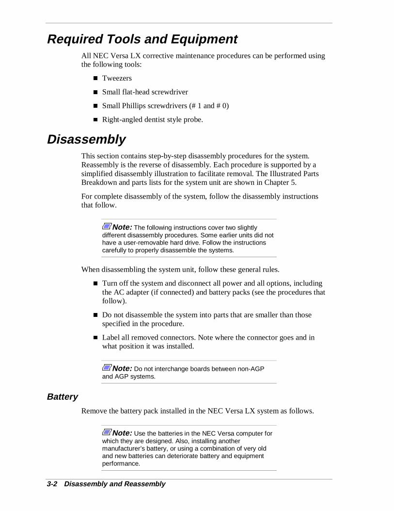
3-2 Disassembly and Reassembly
Required Tools and EquipmentAll NEC Versa LX corrective maintenance procedures can be performed usingthe following tools:
� Tweezers
� Small flat-head screwdriver
� Small Phillips screwdrivers (# 1 and # 0)
� Right-angled dentist style probe.
DisassemblyThis section contains step-by-step disassembly procedures for the system.Reassembly is the reverse of disassembly. Each procedure is supported by asimplified disassembly illustration to facilitate removal. The Illustrated PartsBreakdown and parts lists for the system unit are shown in Chapter 5.
For complete disassembly of the system, follow the disassembly instructionsthat follow.
Note: The following instructions cover two slightlydifferent disassembly procedures. Some earlier units did nothave a user-removable hard drive. Follow the instructionscarefully to properly disassemble the systems.
When disassembling the system unit, follow these general rules.
� Turn off the system and disconnect all power and all options, includingthe AC adapter (if connected) and battery packs (see the procedures thatfollow).
� Do not disassemble the system into parts that are smaller than thosespecified in the procedure.
� Label all removed connectors. Note where the connector goes and inwhat position it was installed.
Note: Do not interchange boards between non-AGPand AGP systems.
BatteryRemove the battery pack installed in the NEC Versa LX system as follows.
Note: Use the batteries in the NEC Versa computer forwhich they are designed. Also, installing anothermanufacturer’s battery, or using a combination of very oldand new batteries can deteriorate battery and equipmentperformance.
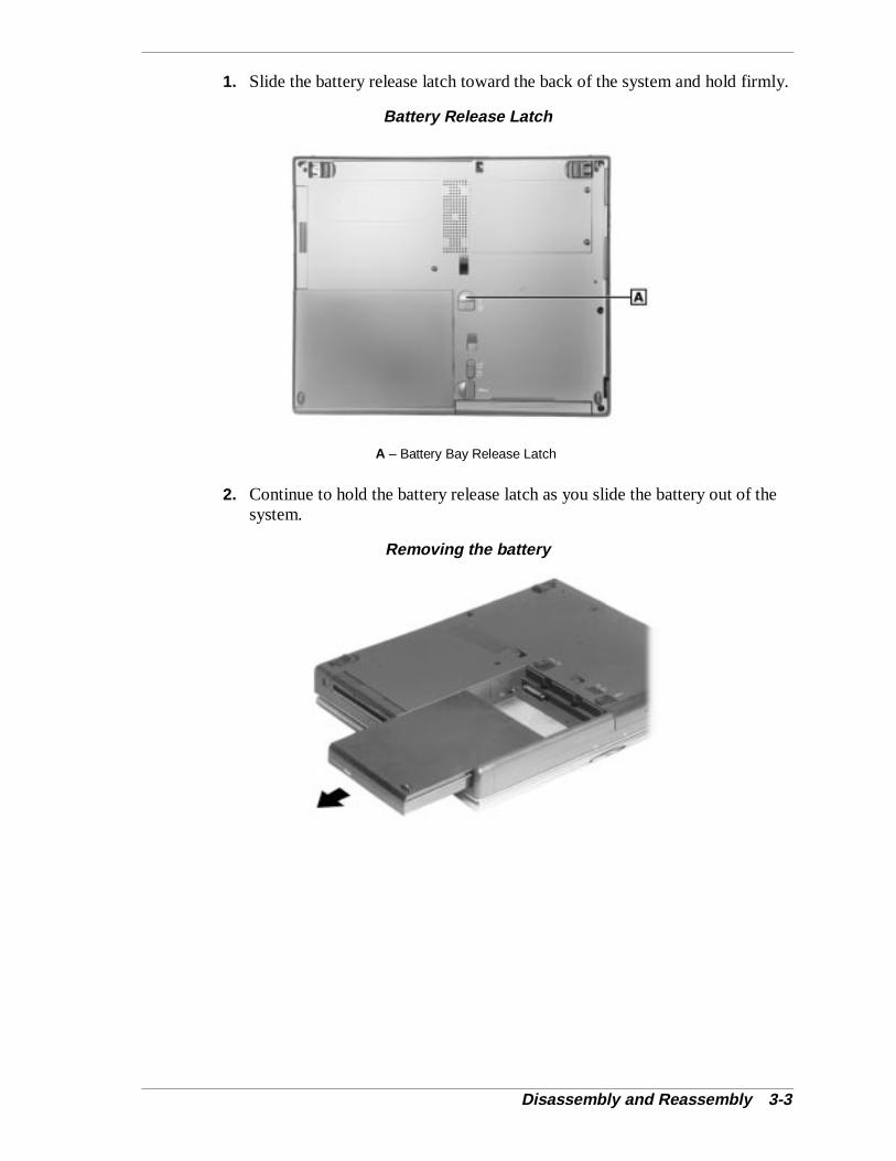
Disassembly and Reassembly 3-3
1. Slide the battery release latch toward the back of the system and hold firmly.
Battery Release Latch
A – Battery Bay Release Latch
2. Continue to hold the battery release latch as you slide the battery out of thesystem.
Removing the battery

3-4 Disassembly and Reassembly
Removing a Device from the VersaBay III
Use the following steps to remove a device from the VersaBay III.
1. Locate the VersaBay III release lock and release latch on the bottom of theunit.
VersaBay III release lock
A – VersaBay Release Lock B – VersaBay Release Latch
2. Slide the lock to the unlocked position before releasing the latch.
3. Slide the latch toward the battery bay and hold it.
4. Slide the device from the system.
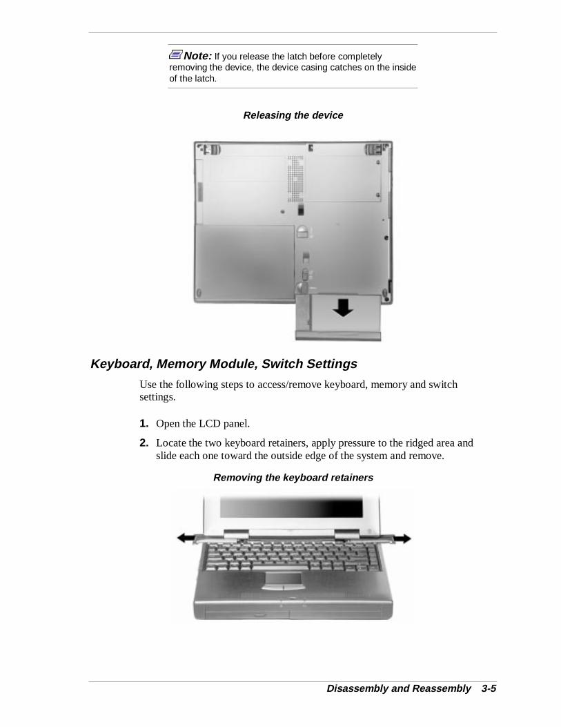
Disassembly and Reassembly 3-5
Note: If you release the latch before completelyremoving the device, the device casing catches on the insideof the latch.
Releasing the device
Keyboard, Memory Module, Switch Settings
Use the following steps to access/remove keyboard, memory and switchsettings.
1. Open the LCD panel.
2. Locate the two keyboard retainers, apply pressure to the ridged area andslide each one toward the outside edge of the system and remove.
Removing the keyboard retainers
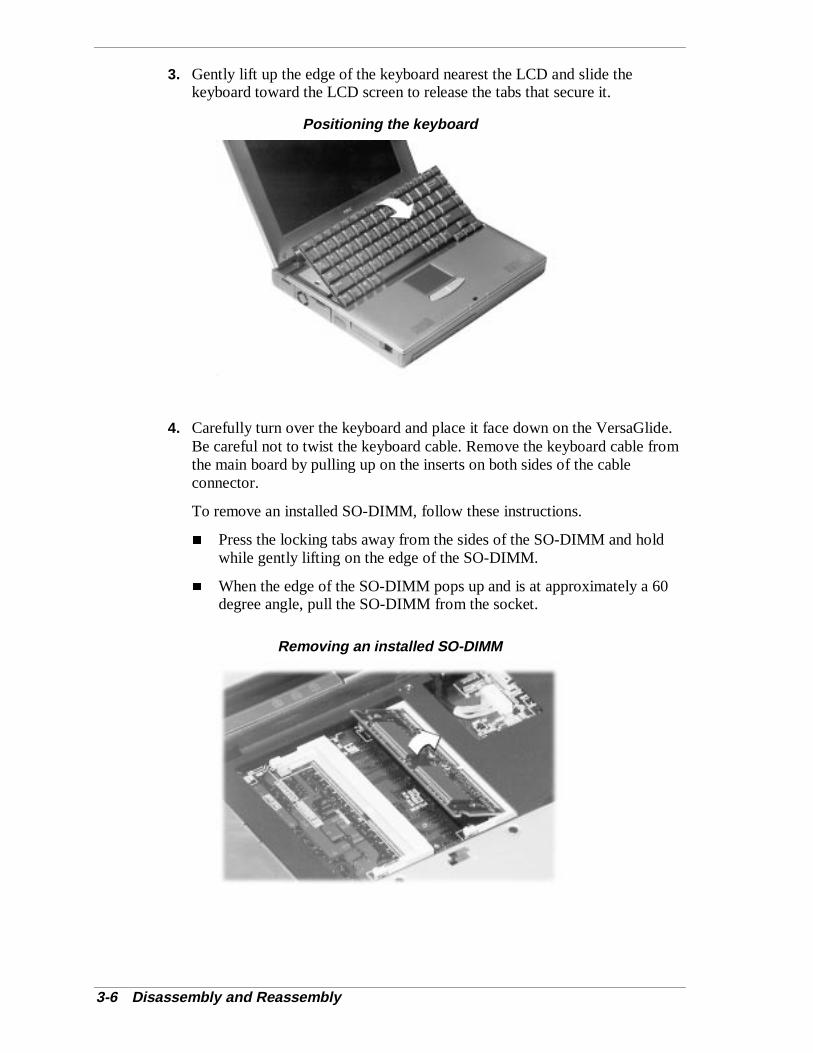
3-6 Disassembly and Reassembly
3. Gently lift up the edge of the keyboard nearest the LCD and slide thekeyboard toward the LCD screen to release the tabs that secure it.
Positioning the keyboard
4. Carefully turn over the keyboard and place it face down on the VersaGlide.Be careful not to twist the keyboard cable. Remove the keyboard cable fromthe main board by pulling up on the inserts on both sides of the cableconnector.
To remove an installed SO-DIMM, follow these instructions.
� Press the locking tabs away from the sides of the SO-DIMM and holdwhile gently lifting on the edge of the SO-DIMM.
� When the edge of the SO-DIMM pops up and is at approximately a 60degree angle, pull the SO-DIMM from the socket.
Removing an installed SO-DIMM
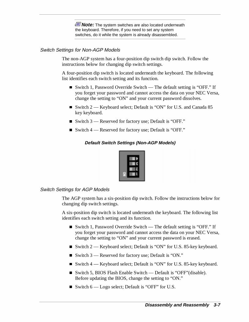
Disassembly and Reassembly 3-7
Note: The system switches are also located underneaththe keyboard. Therefore, if you need to set any systemswitches, do it while the system is already disassembled.
Switch Settings for Non-AGP Models
The non-AGP system has a four-position dip switch dip switch. Follow theinstructions below for changing dip switch settings.
A four-position dip switch is located underneath the keyboard. The followinglist identifies each switch setting and its function.
� Switch 1, Password Override Switch — The default setting is “OFF.” Ifyou forget your password and cannot access the data on your NEC Versa,change the setting to “ON” and your current password dissolves.
� Switch 2 — Keyboard select; Default is “ON” for U.S. and Canada 85key keyboard.
� Switch 3 — Reserved for factory use; Default is “OFF.”
� Switch 4 — Reserved for factory use; Default is “OFF.”
Default Switch Settings (Non-AGP Models)
Switch Settings for AGP Models
The AGP system has a six-position dip switch. Follow the instructions below forchanging dip switch settings.
A six-position dip switch is located underneath the keyboard. The following listidentifies each switch setting and its function.
� Switch 1, Password Override Switch — The default setting is “OFF.” Ifyou forget your password and cannot access the data on your NEC Versa,change the setting to “ON” and your current password is erased.
� Switch 2 — Keyboard select; Default is “ON” for U.S. 85-key keyboard.
� Switch 3 — Reserved for factory use; Default is “ON.”
� Switch 4 — Keyboard select; Default is “ON” for U.S. 85-key keyboard.
� Switch 5, BIOS Flash Enable Switch — Default is “OFF”(disable).Before updating the BIOS, change the setting to “ON.”
� Switch 6 — Logo select; Default is “OFF” for U.S.
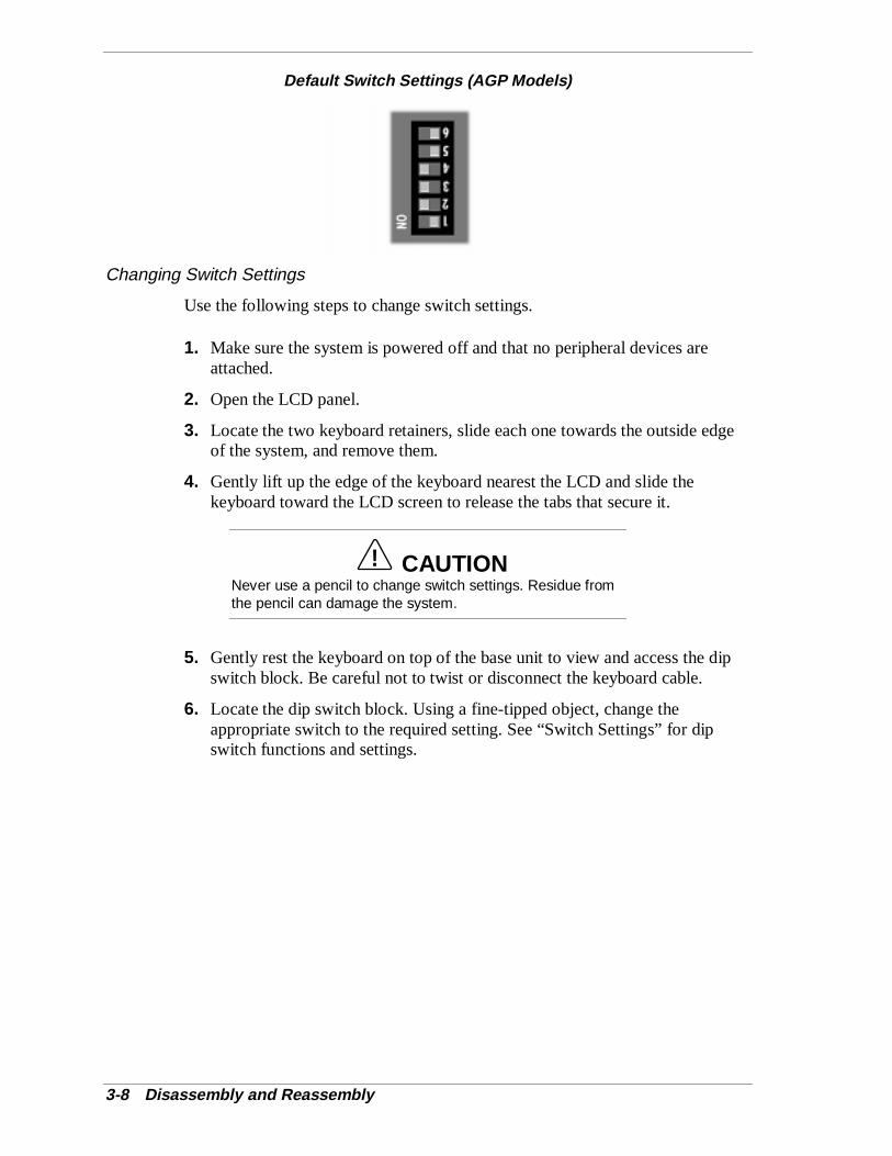
3-8 Disassembly and Reassembly
Default Switch Settings (AGP Models)
Changing Switch Settings
Use the following steps to change switch settings.
1. Make sure the system is powered off and that no peripheral devices areattached.
2. Open the LCD panel.
3. Locate the two keyboard retainers, slide each one towards the outside edgeof the system, and remove them.
4. Gently lift up the edge of the keyboard nearest the LCD and slide thekeyboard toward the LCD screen to release the tabs that secure it.
! CAUTIONNever use a pencil to change switch settings. Residue fromthe pencil can damage the system.
5. Gently rest the keyboard on top of the base unit to view and access the dipswitch block. Be careful not to twist or disconnect the keyboard cable.
6. Locate the dip switch block. Using a fine-tipped object, change theappropriate switch to the required setting. See “Switch Settings” for dipswitch functions and settings.
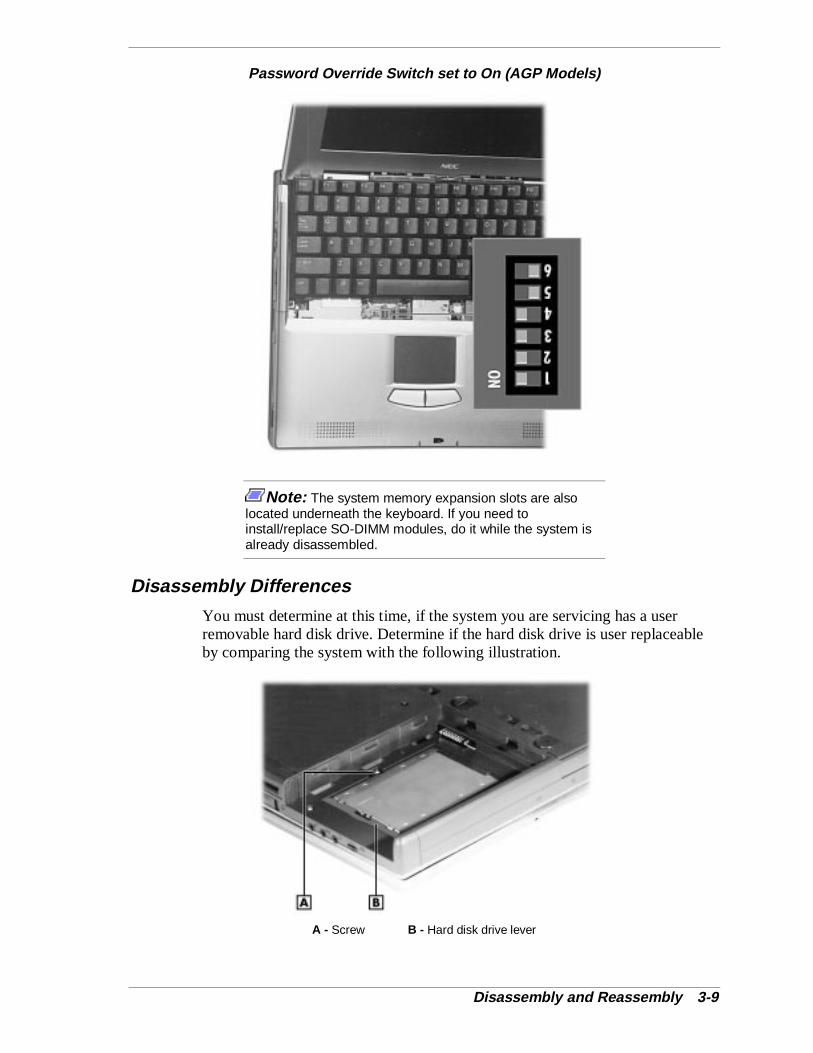
Disassembly and Reassembly 3-9
Password Override Switch set to On (AGP Models)
Note: The system memory expansion slots are alsolocated underneath the keyboard. If you need toinstall/replace SO-DIMM modules, do it while the system isalready disassembled.
Disassembly Differences
You must determine at this time, if the system you are servicing has a userremovable hard disk drive. Determine if the hard disk drive is user replaceableby comparing the system with the following illustration.
A - Screw B - Hard disk drive lever
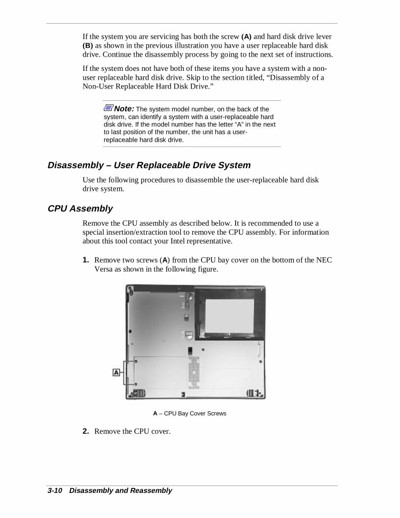
3-10 Disassembly and Reassembly
If the system you are servicing has both the screw (A) and hard disk drive lever(B) as shown in the previous illustration you have a user replaceable hard diskdrive. Continue the disassembly process by going to the next set of instructions.
If the system does not have both of these items you have a system with a non-user replaceable hard disk drive. Skip to the section titled, “Disassembly of aNon-User Replaceable Hard Disk Drive.”
Note: The system model number, on the back of thesystem, can identify a system with a user-replaceable harddisk drive. If the model number has the letter “A” in the nextto last position of the number, the unit has a user-replaceable hard disk drive.
Disassembly – User Replaceable Drive System
Use the following procedures to disassemble the user-replaceable hard diskdrive system.
CPU Assembly
Remove the CPU assembly as described below. It is recommended to use aspecial insertion/extraction tool to remove the CPU assembly. For informationabout this tool contact your Intel representative.
1. Remove two screws (A) from the CPU bay cover on the bottom of the NECVersa as shown in the following figure.
A – CPU Bay Cover Screws
2. Remove the CPU cover.
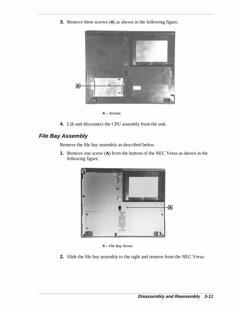
Disassembly and Reassembly 3-11
3. Remove three screws (A) as shown in the following figure.
A – Screws
4. Lift and disconnect the CPU assembly from the unit.
File Bay Assembly
Remove the file bay assembly as described below.
1. Remove one screw (A) from the bottom of the NEC Versa as shown in thefollowing figure.
A – File Bay Screw
2. Slide the file bay assembly to the right and remove from the NEC Versa.
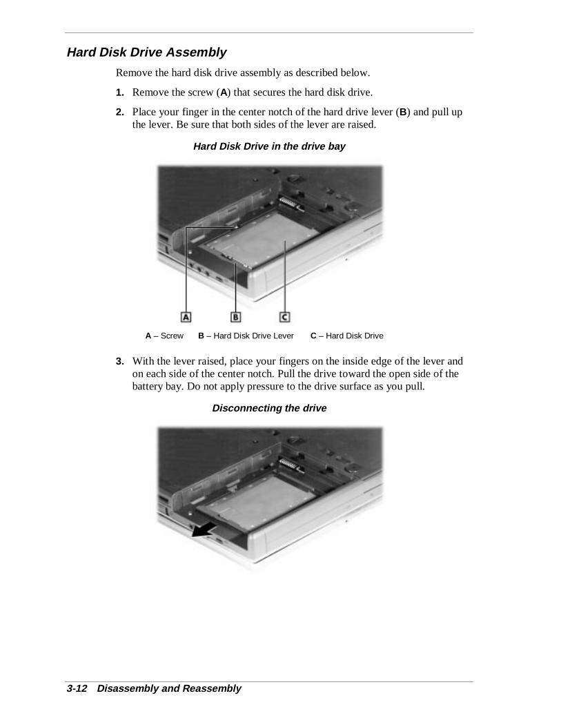
3-12 Disassembly and Reassembly
Hard Disk Drive Assembly
Remove the hard disk drive assembly as described below.
1. Remove the screw (A) that secures the hard disk drive.
2. Place your finger in the center notch of the hard drive lever (B) and pull upthe lever. Be sure that both sides of the lever are raised.
Hard Disk Drive in the drive bay
A – Screw B – Hard Disk Drive Lever C – Hard Disk Drive
3. With the lever raised, place your fingers on the inside edge of the lever andon each side of the center notch. Pull the drive toward the open side of thebattery bay. Do not apply pressure to the drive surface as you pull.
Disconnecting the drive
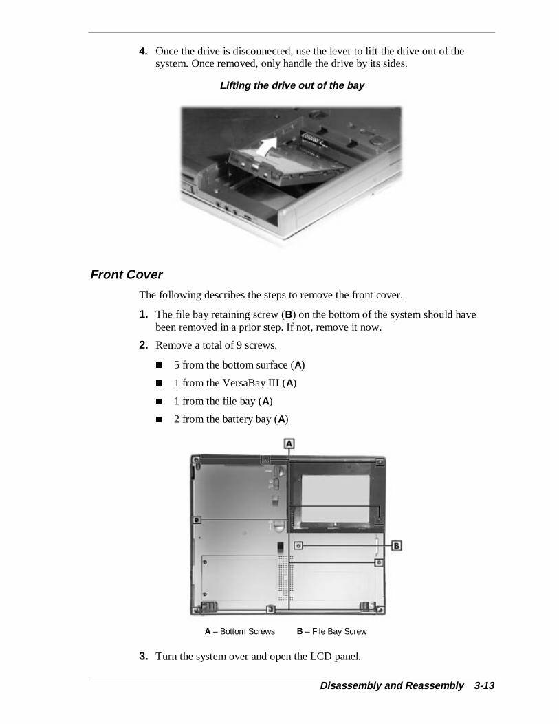
Disassembly and Reassembly 3-13
4. Once the drive is disconnected, use the lever to lift the drive out of thesystem. Once removed, only handle the drive by its sides.
Lifting the drive out of the bay
Front Cover
The following describes the steps to remove the front cover.
1. The file bay retaining screw (B) on the bottom of the system should havebeen removed in a prior step. If not, remove it now.
2. Remove a total of 9 screws.
� 5 from the bottom surface (A)
� 1 from the VersaBay III (A)
� 1 from the file bay (A)
� 2 from the battery bay (A)
A – Bottom Screws B – File Bay Screw
3. Turn the system over and open the LCD panel.

3-14 Disassembly and Reassembly
4. Disconnect the VersaGlide cable from connector P11 (next to the dipswitches) and speaker assembly cable from connector P10. Both are locatedon the main board.
5. Carefully separate and lift the front cover from the bottom assembly, startingon the right and working left.
At this point in the disassembly sequence you can remove the speaker assembly,VersaGlide assembly or LCD panel latch switch assembly, if necessary. If theseitems do no need replacing, skip the next section.
Speaker Assembly, VersaGlide Assembly, LCD Panel Latch Switch Assembly
1. Position the front cover assembly as shown in the following illustration.
A – Speaker Assembly Screws
2. Remove the screws and lift the speaker assembly from the front coverassembly.
VersaGlide Assembly
Remove the VersaGlide and cable assembly instructions as follows.
1. Disconnect the LCD panel switch cable from connector CP16 (A) on theVersaGlide assembly.
2. Remove the four screws (B).
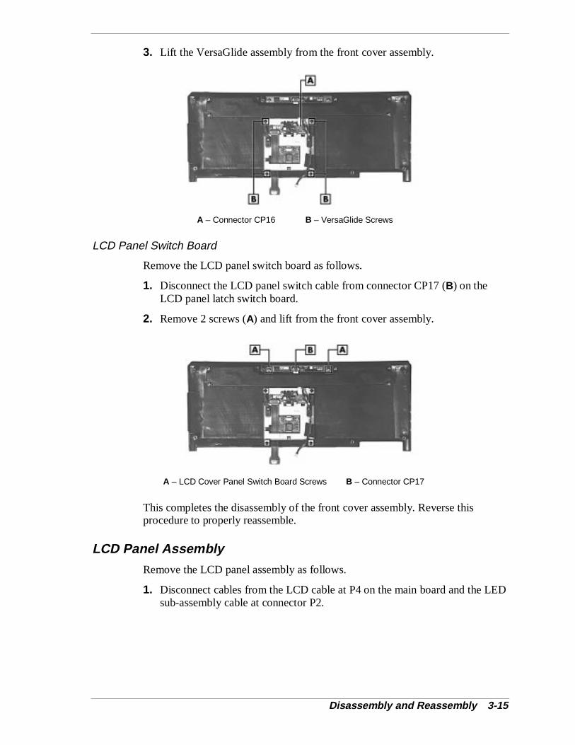
Disassembly and Reassembly 3-15
3. Lift the VersaGlide assembly from the front cover assembly.
A – Connector CP16 B – VersaGlide Screws
LCD Panel Switch Board
Remove the LCD panel switch board as follows.
1. Disconnect the LCD panel switch cable from connector CP17 (B) on theLCD panel latch switch board.
2. Remove 2 screws (A) and lift from the front cover assembly.
A – LCD Cover Panel Switch Board Screws B – Connector CP17
This completes the disassembly of the front cover assembly. Reverse thisprocedure to properly reassemble.
LCD Panel Assembly
Remove the LCD panel assembly as follows.
1. Disconnect cables from the LCD cable at P4 on the main board and the LEDsub-assembly cable at connector P2.

3-16 Disassembly and Reassembly
2. Remove two screws (A) and lift and separate the LCD panel assembly fromthe remainder of the system.
A – LCD Panel Assembly Screws
LED Sub Assembly
The LED sub assembly consists of a board that contains three connectors andstatus LEDs. The connectors are for the LCD panel switch, main board, andmicrophone.
A – Connector CP13 B – Connector CP12C – Connector CP11 D – Microphone
LCD Panel Switch
1. Remove two screws on the hinge bracket.
2. Disconnect the cable at connector CP13 on the LED board.
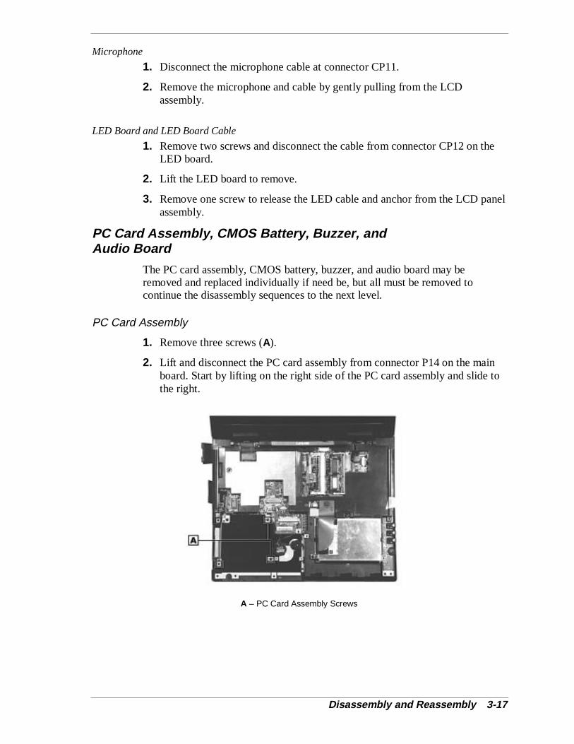
Disassembly and Reassembly 3-17
Microphone
1. Disconnect the microphone cable at connector CP11.
2. Remove the microphone and cable by gently pulling from the LCDassembly.
LED Board and LED Board Cable
1. Remove two screws and disconnect the cable from connector CP12 on theLED board.
2. Lift the LED board to remove.
3. Remove one screw to release the LED cable and anchor from the LCD panelassembly.
PC Card Assembly, CMOS Battery, Buzzer, andAudio Board
The PC card assembly, CMOS battery, buzzer, and audio board may beremoved and replaced individually if need be, but all must be removed tocontinue the disassembly sequences to the next level.
PC Card Assembly
1. Remove three screws (A).
2. Lift and disconnect the PC card assembly from connector P14 on the mainboard. Start by lifting on the right side of the PC card assembly and slide tothe right.
A – PC Card Assembly Screws
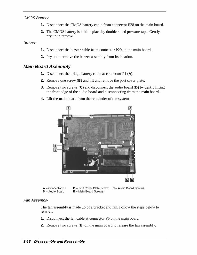
3-18 Disassembly and Reassembly
CMOS Battery
1. Disconnect the CMOS battery cable from connector P28 on the main board.
2. The CMOS battery is held in place by double-sided pressure tape. Gentlypry up to remove.
Buzzer
1. Disconnect the buzzer cable from connector P29 on the main board.
2. Pry up to remove the buzzer assembly from its location.
Main Board Assembly
1. Disconnect the bridge battery cable at connector P1 (A).
2. Remove one screw (B) and lift and remove the port cover plate.
3. Remove two screws (C) and disconnect the audio board (D) by gently liftingthe front edge of the audio board and disconnecting from the main board.
4. Lift the main board from the remainder of the system.
A – Connector P1 B – Port Cover Plate Screw C – Audio Board ScrewsD – Audio Board E – Main Board Screws
Fan Assembly
The fan assembly is made up of a bracket and fan. Follow the steps below toremove.
1. Disconnect the fan cable at connector P5 on the main board.
2. Remove two screws (E) on the main board to release the fan assembly.
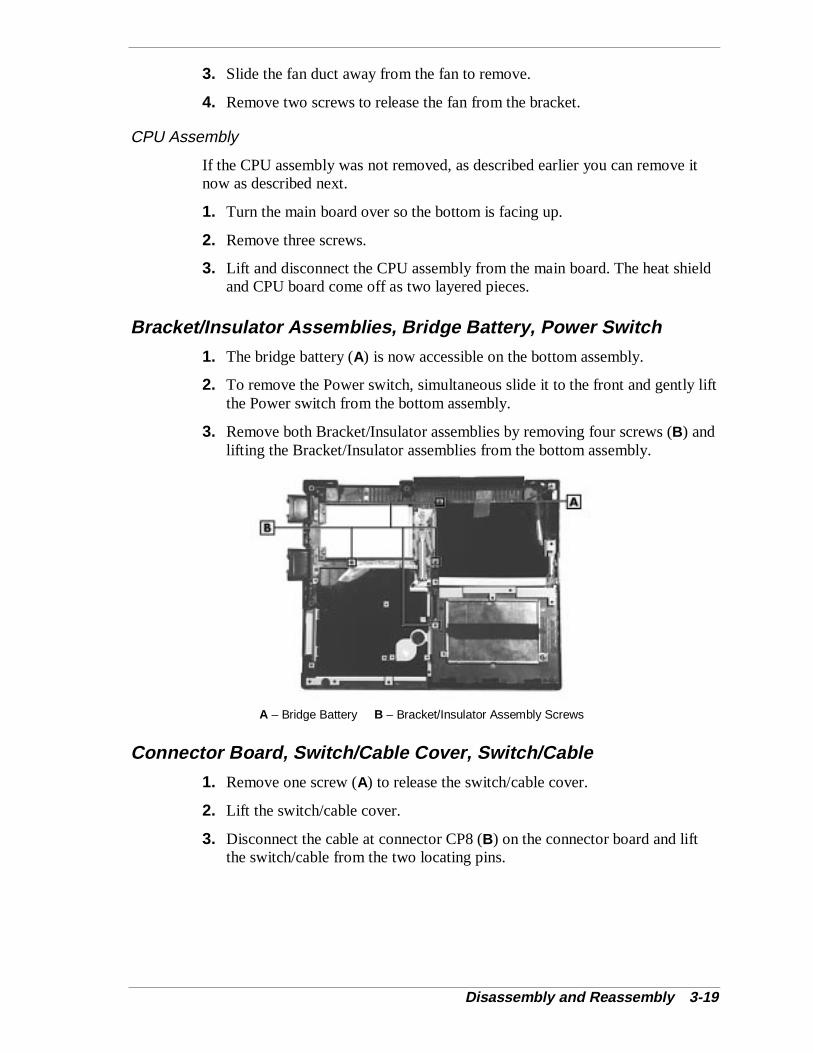
Disassembly and Reassembly 3-19
3. Slide the fan duct away from the fan to remove.
4. Remove two screws to release the fan from the bracket.
CPU Assembly
If the CPU assembly was not removed, as described earlier you can remove itnow as described next.
1. Turn the main board over so the bottom is facing up.
2. Remove three screws.
3. Lift and disconnect the CPU assembly from the main board. The heat shieldand CPU board come off as two layered pieces.
Bracket/Insulator Assemblies, Bridge Battery, Power Switch
1. The bridge battery (A) is now accessible on the bottom assembly.
2. To remove the Power switch, simultaneous slide it to the front and gently liftthe Power switch from the bottom assembly.
3. Remove both Bracket/Insulator assemblies by removing four screws (B) andlifting the Bracket/Insulator assemblies from the bottom assembly.
A – Bridge Battery B – Bracket/Insulator Assembly Screws
Connector Board, Switch/Cable Cover, Switch/Cable
1. Remove one screw (A) to release the switch/cable cover.
2. Lift the switch/cable cover.
3. Disconnect the cable at connector CP8 (B) on the connector board and liftthe switch/cable from the two locating pins.

3-20 Disassembly and Reassembly
4. Remove one screw (B) to release the connector board from the bottomassembly.
A – Screws B – Connector CP8
Bottom Base Assembly
There are doors and tilt feet on the bottom assembly.
� All doors snap in and out.
� To remove the tilt feet open the foot and slightly compress the foursections together and snap out.
Disassembly – Non-User Replaceable Drive System
Use the following procedures to disassemble the non-user replaceable hard diskdrive system.
CPU Assembly
Remove the CPU assembly as described in the following procedure.
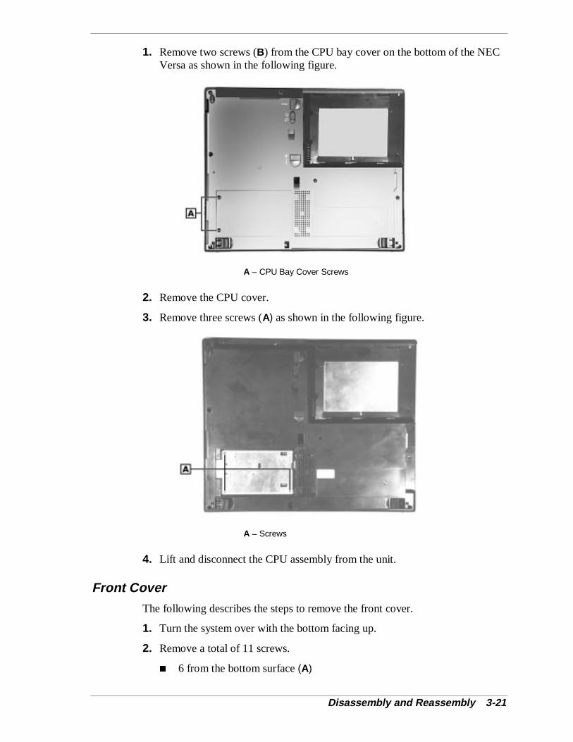
Disassembly and Reassembly 3-21
1. Remove two screws (B) from the CPU bay cover on the bottom of the NECVersa as shown in the following figure.
A – CPU Bay Cover Screws
2. Remove the CPU cover.
3. Remove three screws (A) as shown in the following figure.
A – Screws
4. Lift and disconnect the CPU assembly from the unit.
Front Cover
The following describes the steps to remove the front cover.
1. Turn the system over with the bottom facing up.
2. Remove a total of 11 screws.
� 6 from the bottom surface (A)
3-22 Disassembly and Reassembly
� 1 from the VersaBay III (A)
� 1 from the File Bay (A)
� 3 from the battery bay (A)
A – Bottom Screws
3. Turn the system over and open the LCD panel. Disassembly Sequence 1(Battery Pack, VersaBay III Device and File Bay Device) and 2 (Keyboard)should be completed as described in previous sections of this chapter.
4. Disconnect the VersaGlide cable from connector P11 and speaker assemblycable from connector P10 both located on the main board.
5. Carefully separate and lift the front cover from the bottom assembly, startingon the right and working left.
At this point in the disassembly sequence you can remove the speaker assembly,VersaGlide assembly or LCD panel latch switch assembly, if necessary. If theseitems do no need replacing, skip the next section and go to the followingsequence.
Disassembly and Reassembly 3-23
Speaker Assembly, VersaGlide Assembly, LCD Panel Latch Switch Assembly
1. Position the front cover assembly as shown in the following illustration.
A – Screws
2. Remove the speaker assembly by removing 6 screws. Lift the speakerassembly from the front cover assembly.
VersaGlide Assembly
Remove the VersaGlide and cable assembly instructions as follows.
1. Disconnect the LCD panel switch cable from connector CP16 (A) on theVersaGlide assembly.
2. Remove the four screws (B).
3. Lift the VersaGlide assembly from the front cover assembly.
A – Connector CP16 B – Speaker Assembly Screws
LCD Panel Switch Board
Remove the LCD panel switch boards instructions as follows.
1. Disconnect the LCD panel switch cable from connector CP17 (B) on theLCD panel latch switch board.
3-24 Disassembly and Reassembly
2. Remove 2 screws (A) and lift from the front cover assembly.
A – LCD Cover Panel Switch Board Screws B – Connector CP17
This completes the disassembly of the front cover assembly. Reverse thisprocedure to properly reassemble.
LCD Panel Assembly
Remove the LCD Panel assembly as follows.
1. Disconnect cables from the LCD cable at P4 on the main board and the LEDsub-assembly cable at connector P2.
2. Remove two screws (A) and lift and separate the LCD panel assembly fromthe remainder of the system.
A – LCD Panel Assembly Screws
Disassembly and Reassembly 3-25
LED Sub Assembly
The LED sub assembly consists of a board that contains three connectors andstatus LEDs. The connectors are for the LCD panel switch, main board, andmicrophone.
A – Connector CP13 B – Connector CP12C – Connector CP11 D – Microphone
LCD Panel Switch
1. Remove two screws on the hinge bracket.
2. Disconnect the cable at connector CP13 on the LED board.
Microphone
1. Disconnect the microphone cable at connector CP11.
2. Remove the microphone and cable by gently pulling from the LCDassembly.
LED Board and LED Board Cable
1. Remove two screws and disconnect the cable from connector CP12 on theLED board.
2. Lift the LED board to remove.
3. Remove one screw to release the LED cable and anchor from the LCD panelassembly.
Hard Drive and PC Card Assemblies, CMOS Battery, Buzzer,Audio Board
The hard drive assembly, PC card assembly, CMOS battery, buzzer, audio boardmay be removed and replaced individually or all must be removed to continuethe disassembly sequences.
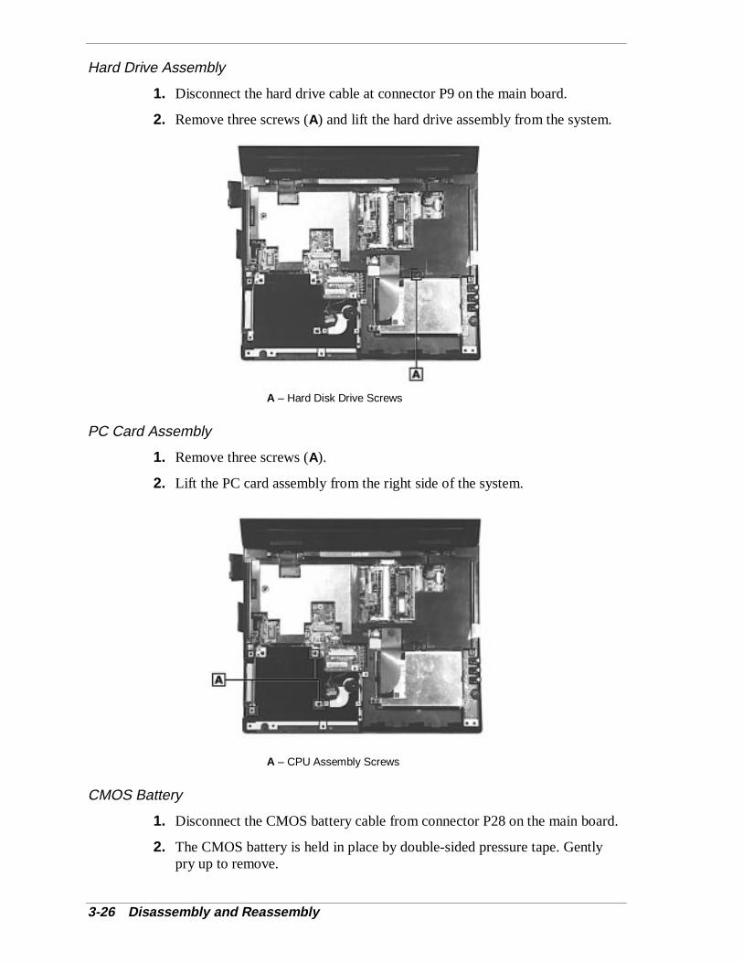
3-26 Disassembly and Reassembly
Hard Drive Assembly
1. Disconnect the hard drive cable at connector P9 on the main board.
2. Remove three screws (A) and lift the hard drive assembly from the system.
A – Hard Disk Drive Screws
PC Card Assembly
1. Remove three screws (A).
2. Lift the PC card assembly from the right side of the system.
A – CPU Assembly Screws
CMOS Battery
1. Disconnect the CMOS battery cable from connector P28 on the main board.
2. The CMOS battery is held in place by double-sided pressure tape. Gentlypry up to remove.
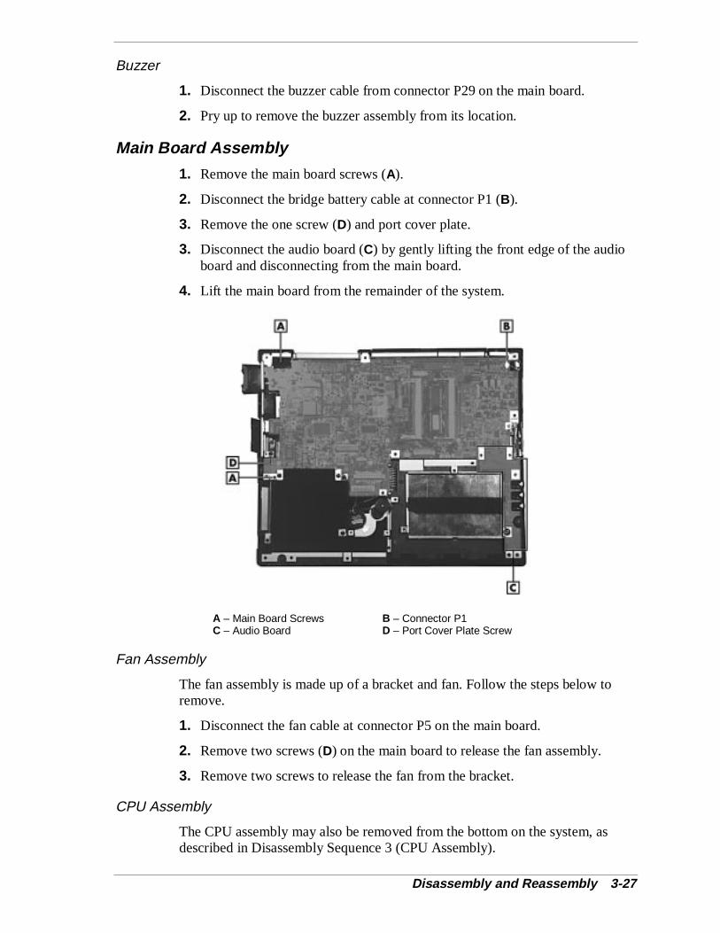
Disassembly and Reassembly 3-27
Buzzer
1. Disconnect the buzzer cable from connector P29 on the main board.
2. Pry up to remove the buzzer assembly from its location.
Main Board Assembly
1. Remove the main board screws (A).
2. Disconnect the bridge battery cable at connector P1 (B).
3. Remove the one screw (D) and port cover plate.
3. Disconnect the audio board (C) by gently lifting the front edge of the audioboard and disconnecting from the main board.
4. Lift the main board from the remainder of the system.
A – Main Board Screws B – Connector P1C – Audio Board D – Port Cover Plate Screw
Fan Assembly
The fan assembly is made up of a bracket and fan. Follow the steps below toremove.
1. Disconnect the fan cable at connector P5 on the main board.
2. Remove two screws (D) on the main board to release the fan assembly.
3. Remove two screws to release the fan from the bracket.
CPU Assembly
The CPU assembly may also be removed from the bottom on the system, asdescribed in Disassembly Sequence 3 (CPU Assembly).
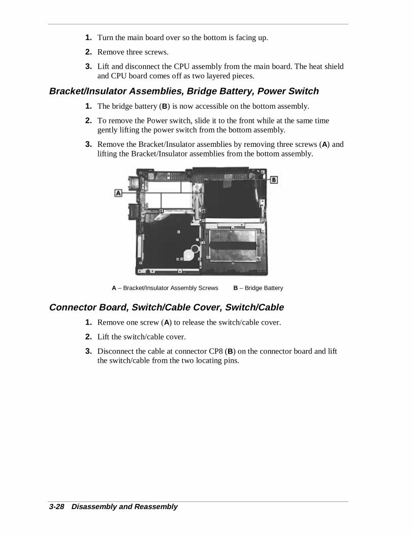
3-28 Disassembly and Reassembly
1. Turn the main board over so the bottom is facing up.
2. Remove three screws.
3. Lift and disconnect the CPU assembly from the main board. The heat shieldand CPU board comes off as two layered pieces.
Bracket/Insulator Assemblies, Bridge Battery, Power Switch
1. The bridge battery (B) is now accessible on the bottom assembly.
2. To remove the Power switch, slide it to the front while at the same timegently lifting the power switch from the bottom assembly.
3. Remove the Bracket/Insulator assemblies by removing three screws (A) andlifting the Bracket/Insulator assemblies from the bottom assembly.
A – Bracket/Insulator Assembly Screws B – Bridge Battery
Connector Board, Switch/Cable Cover, Switch/Cable
1. Remove one screw (A) to release the switch/cable cover.
2. Lift the switch/cable cover.
3. Disconnect the cable at connector CP8 (B) on the connector board and liftthe switch/cable from the two locating pins.

Disassembly and Reassembly 3-29
4. Remove one screw (A) to release the connector board from the bottomassembly.
A – Screws B – Connector CP8
Bottom Base Assembly
There are doors and tilt feet on the bottom assembly.
� All doors snap in and out.
� To remove the tilt feet open the foot and slightly compress the foursections together and snap out.
ReassemblyReassembly is the reverse of the disassembly process. Use care to insure that allcables and screws are returned to their proper positions.
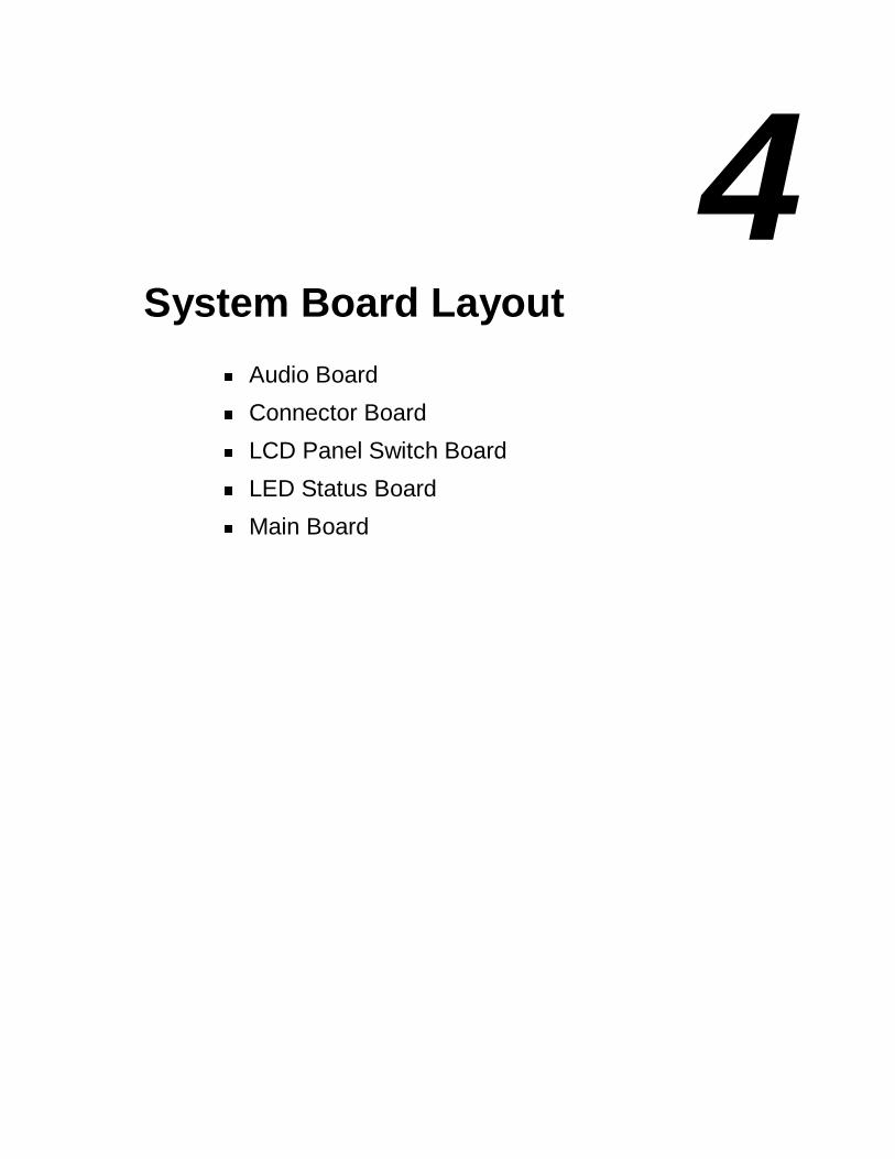
4System Board Layout
� Audio Board
� Connector Board
� LCD Panel Switch Board
� LED Status Board
� Main Board

4-2 System Board Layout
Audio Board
A – Connector P31 (underside)
Connector Board
A – Connector CP10 B – Connector CP9C – Connector CP8 D – Connector CP7
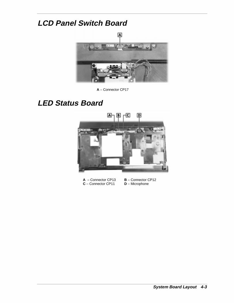
System Board Layout 4-3
LCD Panel Switch Board
A – Connector CP17
LED Status Board
A – Connector CP13 B – Connector CP12C – Connector CP11 D – Microphone
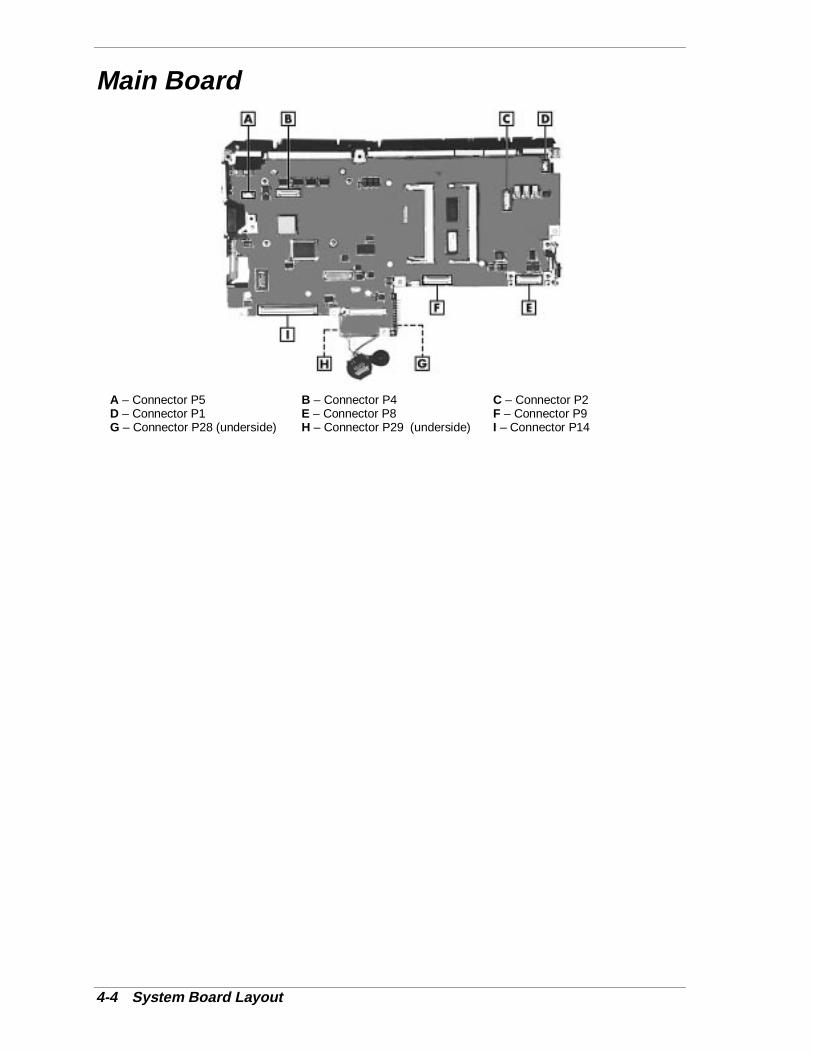
4-4 System Board Layout
Main Board
A – Connector P5 B – Connector P4 C – Connector P2D – Connector P1 E – Connector P8 F – Connector P9G – Connector P28 (underside) H – Connector P29 (underside) I – Connector P14

5 Illustrated Parts Breakdown
!"Illustrated Parts Breakdown (Non-AGP Models) !"Parts List (Non-AGP Models) !"Illustrated Parts Breakdown (AGP Models) !"Parts List (AGP Models)
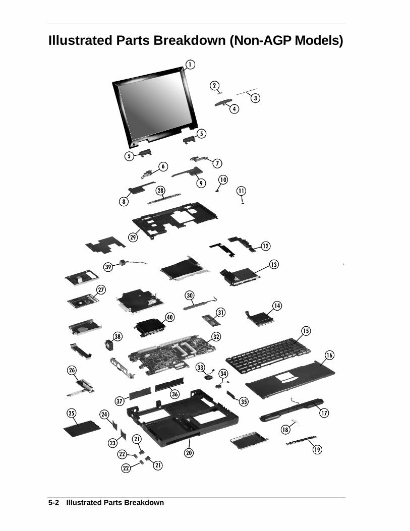
5-2 Illustrated Parts Breakdown
Illustrated Parts Breakdown (Non-AGP Models)
Illustrated Parts Breakdown 5-3
Parts List (Non-AGP Models) The following table contains a listing of the field-replaceable parts and corresponding part numbers for non-AGP models.
Field-Replaceable Parts List Item Description Part Number
1 LCD Panel Sub Assembly 12.1 - inch 13.3 - inch 14.1 - inch
158-057557-000 158-057558-000 158-057559-000
2 LCD Lock Spring 136-628895-A
3 LCD Lock Shaft 136-636754-A
4 LCD Lock Lever 136-639307-001A
5 Hinge Cap 136-639511-001A
6 Tilt Unit (left) 808-811158-001A
7 Tilt Unit (right) 808-811158-002A
8 Corner Cap (L) 136-639512-001A
9 Corner Cap (R) 136-639512-002A
10 LCD Rubber Cushion 136-639309-001B
11 Screw Hole Cover 136-639310-001A
12 Audio Board 136-243483-001A includes items # 23 & 24
13 Hard Drive Assembly 2GB 3GB 5GB
808-877280-304A 808-877329-124A 808-877329-304A
14 Glide Point Sub Assembly FRU 158-057555-000
15 Keyboard V105(US) 808-897300-501A
16 Front Cover Assembly without Glide Point 136-243484-001A
17 Speaker Cable Assembly 808-878090-001A
18 LED/Glide Point Cable 808-742980-002A
19 LED Package (Front) Sub Assembly 136-243472-001A
20a Bottom Base Assembly 136-243458-001A
20b Bottom Base Assembly (removable hard disk drive) 136-243684-001A
21 Tilt Foot 136-639509-001A
22 Rubber Foot 136-639531-001A
23 USB Cap 136-243477-001A
24 TV Cap Assembly 136-243476-001A
25 CPU Cap 136-639508-001A
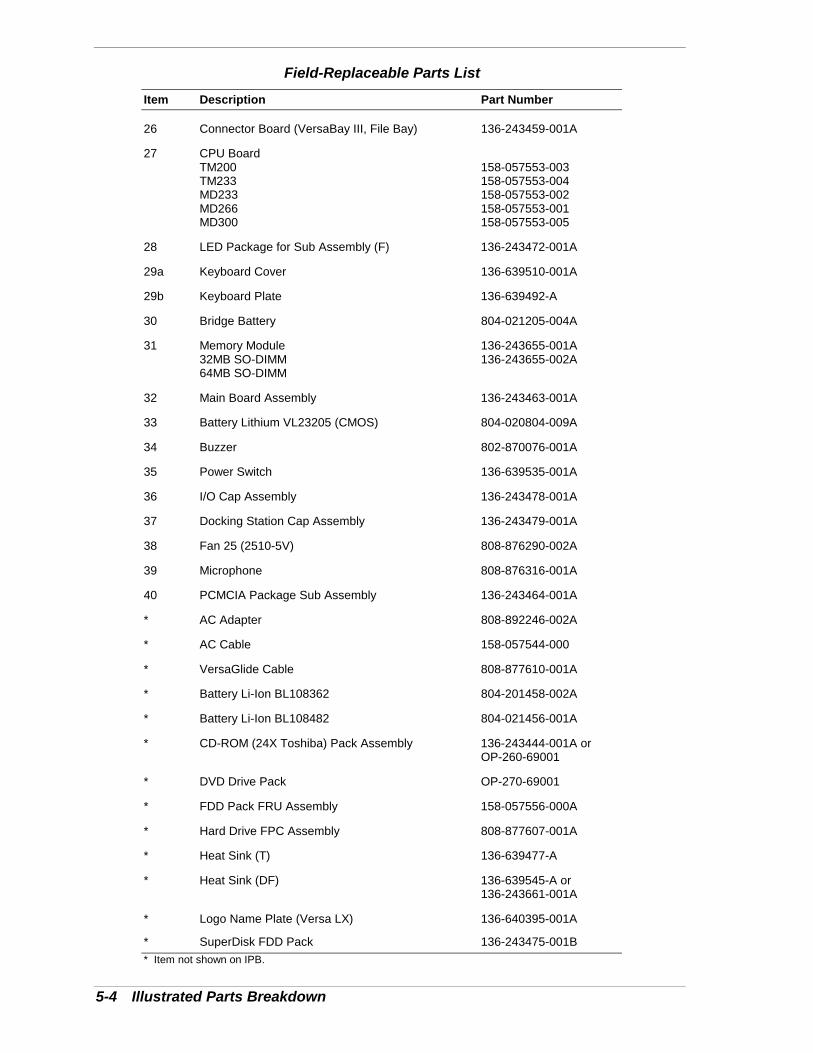
5-4 Illustrated Parts Breakdown
Field-Replaceable Parts List
Item Description Part Number
26 Connector Board (VersaBay III, File Bay) 136-243459-001A
27 CPU Board TM200 TM233 MD233 MD266 MD300
158-057553-003 158-057553-004 158-057553-002 158-057553-001 158-057553-005
28 LED Package for Sub Assembly (F) 136-243472-001A
29a Keyboard Cover 136-639510-001A
29b Keyboard Plate 136-639492-A
30 Bridge Battery 804-021205-004A
31 Memory Module 32MB SO-DIMM 64MB SO-DIMM
136-243655-001A 136-243655-002A
32 Main Board Assembly 136-243463-001A
33 Battery Lithium VL23205 (CMOS) 804-020804-009A
34 Buzzer 802-870076-001A
35 Power Switch 136-639535-001A
36 I/O Cap Assembly 136-243478-001A
37 Docking Station Cap Assembly 136-243479-001A
38 Fan 25 (2510-5V) 808-876290-002A
39 Microphone 808-876316-001A
40 PCMCIA Package Sub Assembly 136-243464-001A
* AC Adapter 808-892246-002A
* AC Cable 158-057544-000
* VersaGlide Cable 808-877610-001A
* Battery Li-Ion BL108362 804-201458-002A
* Battery Li-Ion BL108482 804-021456-001A
* CD-ROM (24X Toshiba) Pack Assembly 136-243444-001A or OP-260-69001
* DVD Drive Pack OP-270-69001
* FDD Pack FRU Assembly 158-057556-000A
* Hard Drive FPC Assembly 808-877607-001A
* Heat Sink (T) 136-639477-A
* Heat Sink (DF) 136-639545-A or 136-243661-001A
* Logo Name Plate (Versa LX) 136-640395-001A
* SuperDisk FDD Pack 136-243475-001B * Item not shown on IPB.
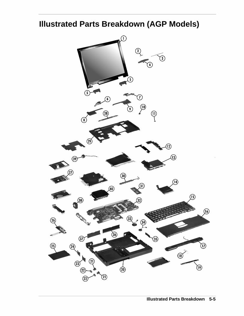
Illustrated Parts Breakdown 5-5
Illustrated Parts Breakdown (AGP Models)
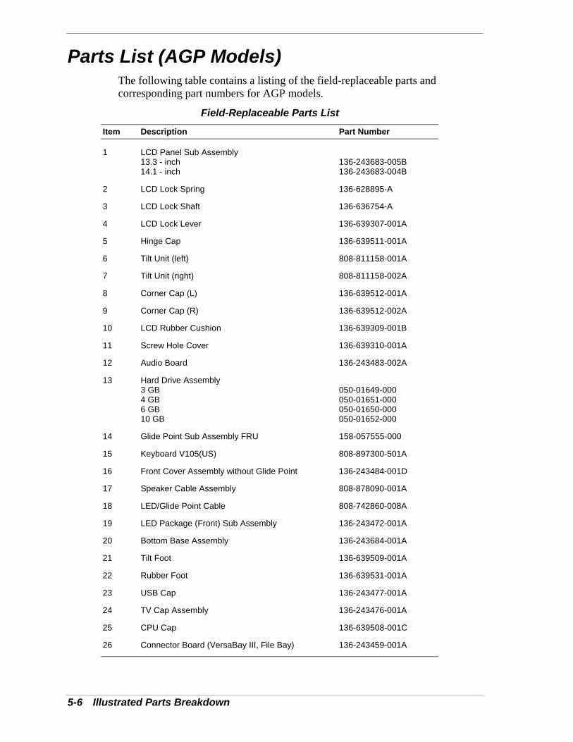
5-6 Illustrated Parts Breakdown
Parts List (AGP Models) The following table contains a listing of the field-replaceable parts and corresponding part numbers for AGP models.
Field-Replaceable Parts List Item Description Part Number
1 LCD Panel Sub Assembly 13.3 - inch 14.1 - inch
136-243683-005B 136-243683-004B
2 LCD Lock Spring 136-628895-A
3 LCD Lock Shaft 136-636754-A
4 LCD Lock Lever 136-639307-001A
5 Hinge Cap 136-639511-001A
6 Tilt Unit (left) 808-811158-001A
7 Tilt Unit (right) 808-811158-002A
8 Corner Cap (L) 136-639512-001A
9 Corner Cap (R) 136-639512-002A
10 LCD Rubber Cushion 136-639309-001B
11 Screw Hole Cover 136-639310-001A
12 Audio Board 136-243483-002A
13 Hard Drive Assembly 3 GB 4 GB 6 GB 10 GB
050-01649-000 050-01651-000 050-01650-000 050-01652-000
14 Glide Point Sub Assembly FRU 158-057555-000
15 Keyboard V105(US) 808-897300-501A
16 Front Cover Assembly without Glide Point 136-243484-001D
17 Speaker Cable Assembly 808-878090-001A
18 LED/Glide Point Cable 808-742860-008A
19 LED Package (Front) Sub Assembly 136-243472-001A
20 Bottom Base Assembly 136-243684-001A
21 Tilt Foot 136-639509-001A
22 Rubber Foot 136-639531-001A
23 USB Cap 136-243477-001A
24 TV Cap Assembly 136-243476-001A
25 CPU Cap 136-639508-001C
26 Connector Board (VersaBay III, File Bay) 136-243459-001A
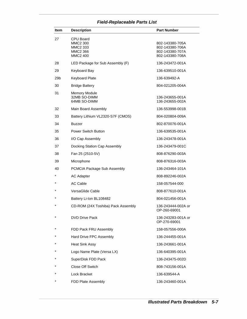
Illustrated Parts Breakdown 5-7
Field-Replaceable Parts List
Item Description Part Number
27 CPU Board MMC2 300 MMC2 333 MMC2 366 MMC2 400
802-143380-705A 802-143380-706A 802-143380-707A 802-143380-708A
28 LED Package for Sub Assembly (F) 136-243472-001A
29 Keyboard Bay 136-639510-001A
29b Keyboard Plate 136-639492-A
30 Bridge Battery 804-021205-004A
31 Memory Module 32MB SO-DIMM 64MB SO-DIMM
136-243655-001A 136-243655-002A
32 Main Board Assembly 136-553998-001B
33 Battery Lithium VL2320-S7F (CMOS) 804-020804-009A
34 Buzzer 802-870076-001A
35 Power Switch Button 136-639535-001A
36 I/O Cap Assembly 136-243478-001A
37 Docking Station Cap Assembly 136-243479-001C
38 Fan 25 (2510-5V) 808-876290-003A
39 Microphone 808-876316-003A
40 PCMCIA Package Sub Assembly 136-243464-101A
* AC Adapter 808-892246-002A
* AC Cable 158-057544-000
* VersaGlide Cable 808-877610-001A
* Battery Li-Ion BL108482 804-021456-001A
* CD-ROM (24X Toshiba) Pack Assembly 136-243444-002A or OP-260-69001
* DVD Drive Pack 136-243283-001A or OP-270-69001
* FDD Pack FRU Assembly 158-057556-000A
* Hard Drive FPC Assembly 136-244455-001A
* Heat Sink Assy 136-243661-001A
* Logo Name Plate (Versa LX) 136-640395-001A
* SuperDisk FDD Pack 136-243475-002D
* Close Off Switch 808-743156-001A
* Lock Bracket 136-639544-A
* FDD Plate Assembly 136-243460-001A
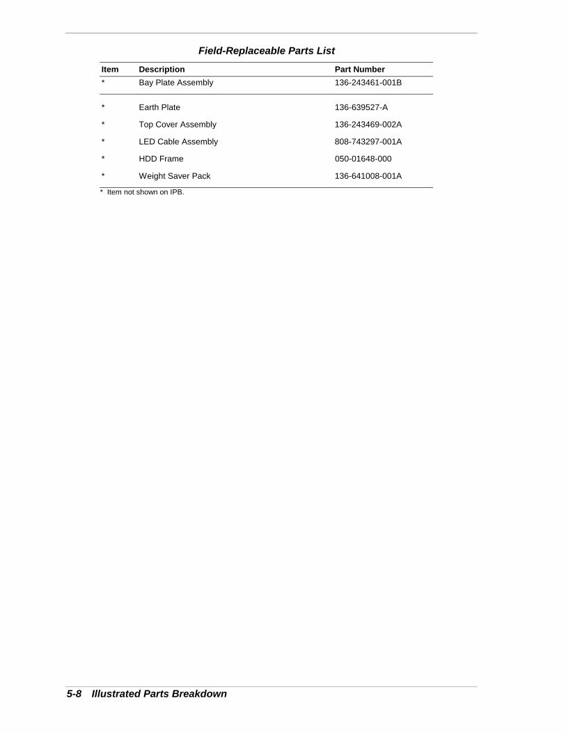
5-8 Illustrated Parts Breakdown
Field-Replaceable Parts List
Item Description Part Number * Bay Plate Assembly 136-243461-001B
* Earth Plate 136-639527-A
* Top Cover Assembly 136-243469-002A
* LED Cable Assembly 808-743297-001A
* HDD Frame 050-01648-000
* Weight Saver Pack 136-641008-001A
* Item not shown on IPB.
6Preventive Maintenance
� Cleaning the Notebook Exterior
� Cleaning the Notebook Interior
� Protecting Disk Drive
� Handling the Battery Pack
� Maintaining the LCD Quality
6-2 Preventive Maintenance
Preventive maintenance is limited to cleaning the plastic case, the keyboard, thedisplay screen, and the diskette drive heads, as required.
Note: Remove the battery and disconnect the ACadapter before performing any maintenance. Voltage ispresent inside the system unit and LCD even after thesystem is turned off.
Cleaning the Notebook ExteriorUse the steps below to clean the outer surface of the system.
1. Power off the system and remove all battery packs. Unplug all cablesconnected to the system.
2. Wipe the outside of the system, keyboard, and display with a soft, cleancloth. Remove stains with a damp, almost dry cloth. Use glass cleaner toclean the LCD. Apply the glass cleaner directly to the cloth and then wipethe LCD. Do not use solvents or strong, abrasive cleaners on any part of thesystem.
3. Clean the keys with a damp cloth. A small, soft-bristle brush may be used toclean between the keys. Make sure to use a damp cloth (not wet) to preventmoisture from seeping between the keyboard and the metal plate, possiblydamaging the components under the keys. If the keyboard gets wet,thoroughly dry it before reassembling the system unit.
Cleaning the Notebook InteriorWhen servicing the inside of the notebook, remove dust and other foreignparticles from inside the system unit as follows:
1. Remove the top cover and keyboard using the disassembly proceduresdiscussed in the section, Disassembly and Reassembly, in Chapter 3.
2. Dust or vacuum (with a rubber-tipped nozzle) the inside of the system,particularly the motherboard surface. Use care to avoid damaging ordislodging any components or cables.
3. Inspect all cables connectors for damage. Ensure that connectors are seatedproperly before replacing the cover.
Protecting the Disk DrivesTo protect the disk drives and data, back up the system disk periodically ondiskettes. Periodically use a head-cleaning diskette in the disk drive to prolongthe life of the drive and to help maintain data integrity.
Here are some maintenance procedures to use when servicing a hard disk:
� Always back up the data files from the hard disk.
Preventive Maintenance 6-3
� Run a virus detecting program to check for possible virus infected areason the hard disk.
� Use the preinstalled ScanDisk program to correct any errors found in thedirectory and File Allocation Table (FAT). This also frees up space fromany unused sectors.
� Never turn the computer off when the hard disk is being accessed.
� Never move or raise the computer while the hard disk is being accessed.Be especially careful not to jar the hard disk during access, this can causea hard disk crash.
� Use hard disk maintenance program like DEFRAG under DOS, oracquire Norton Utilities SPEEDISK programs. These programsreorganize your hard disk by eliminating fragmentation and improve thehard disk access time.
Handling the Battery PackThe battery pack furnished with the computer requires reasonable care andhandling to ensure efficient operation and maximum life. Periodically inspectthe battery terminals and the batteries for evidence of corrosion and oxidebuild-up.
To ensure that the battery pack endures for a normal life cycle, always observethe following precautions when handling the battery packs:
� Do not drop the battery packs or subject them to excessive shock andvibration.
� Do not expose the battery packs to direct sunlight, moisture, chemicalcompounds, or extreme heat.
� Do not disassemble the battery packs.
� Do not use the battery packs to power other devices.
� Do not short the battery leads or connect the battery with reversedpolarity.
� Never attempt to charge the battery packs in any way other than asdescribed in this manual and the user’s guide.
� Always charge the battery packs as soon as possible after a low batteryindication.
6-4 Preventive Maintenance
Maintaining the LCD QualityWhen it comes to screen problems, heat plays a big part. After a good workingsession, the typical routine is to shut the machine and close the cover. Thedisplay surface (no matter what type it is) radiates heat. When you close thecover, you trap the heat against the screen. Make sure to leave the computer'scover open for about ten minutes while the heat disperses, before closing theLCD.

7Troubleshooting
� Quick Troubleshooting
� Helpful Questions
7-2 Troubleshooting
Quick TroubleshootingThis section summarizes problems that may develop during system operationand lists suggested corrective actions.
Quick Troubleshooting
Problem Corrective Action
No power Check that the AC adapter is plugged into thepower connector of the system. Also, check thatthe AC adapter is plugged into a properlygrounded AC power outlet.
If using the battery as the main power source,check if the battery pack is the right type, ischarged, and is inserted correctly.
Check the main board of the system. Is it insertedinto the CPU board connector properly?Otherwise, replace the main board.
Data on the LCD is unreadable Check LCD Panel View Expansion in BIOS,Press Fn-F10 to toggle Panel View Expansion forDOS mode.
Check if installed VGA driver is correct.
Check the VGA controller chip on the main boardfor any loose soldering.
Replace the main board.
Battery power does not last long Make sure that the power management featuresare enabled.
Recharge the battery pack for 2 hours or up to100% before using again.
Replace the battery pack.
System halts during boot sequence Check condition of selected boot device (diskette,hard disk or CD-ROM) for bad boot track orincorrect O/S files.
Try booting from a new bootable diskette andrecopy or repartition hard disk.
Check for any BIOS error messages on thedisplay screen.
Replace the CPU board or main board.
I/O processing malfunctions Check the connections of all internal devices.
Replace the CPU board or main board.
Diskette or SuperDisk does not work Check diskette type is correct or not faulty.
Replace the diskette drive.
Replace the main board.
Troubleshooting 7-3
Quick Troubleshooting
Problem Corrective Action
Hard disk drive malfunction Check if hard disk drive is set properly on CMOSSetup.
Check the drive connections.
Check if the disk drive is good.
Replace the CPU board or main board.
Memory malfunction Check if the memory module is inserted properly.
Replace the memory module.
Replace the CPU board.
External keyboard or PS/2 mouse doesnot work
Check if keyboard or mouse is connectedproperly. Check Y adapter if it is being used.Power off system first before plugging in thedevice.
Replace the keyboard or mouse.
Replace the CPU board or main board.
Serial device does not work Check if device driver is installed properly.
Check if serial device is connected properly.
Check the device drive installation for any IRQ orI/O address conflict.
Replace serial device.
Check the I/O controller chip on the main boardfor any cold or loose soldering.
Replace the I/O board.
PC card does not work Check the PC card driver installation for any IRQor I/O address conflict.
Check if the PC card is inserted properly and allconnections are set.
If the PC card is a Type II card, install it in thesystem’s other PC card slot.
Replace the PC card.
Replace the main board.
NEC VersaGlide does not work Check if PS/2 or Alps mouse driver is properlyinstalled.
Check VersaGlide cable inside the system if it isinserted properly.
Clean VersaGlide surface.
Check the keyboard controller chip for any coldor loose soldering.
Replace the main board.

7-4 Troubleshooting
Quick Troubleshooting
Problem Corrective Action
Parallel device does not work Check all connections.
Check if external device is turned on.
Check the device drive installation for any IRQ orI/O address conflict.
Test another parallel device.
Check I/O controller chip on the main board forany cold or loosed soldering.
Replace the main board.
Helpful QuestionsHere are some helpful questions to ask when troubleshooting the notebook:
� Is there any external power source connected to the computer?
� Is the battery fully charged?
� Is the computer turned on and the Power LED activated?
� Is the LCD display switched to the external monitor?
� Are all cables and devices connected properly and securely?
� Are all needed device drivers installed properly?
� Have you checked the AUTOEXEC.BAT and CONFIG.SYS files forerrors?
� Is the Suspend Mode activated? Press any key or press the Power switchto power on the system.
8Getting Services and Support
! Services and Support Contact Information
! NEC CSD Web
! NEC CSD FTP Sites
! Email/Fax to Support Services
! NEC CSD Bulletin Board
! NEC CSD Support Services
! NEC CSD Customer Assistance Center

8-2 Getting Services and Support
Services and Support Contact InformationNEC CSD Services and Support
Service Contact Information
NEC CSD Web and FTP Sites Web address: www.nec-computers.com
FTP site: ftp.neccsdeast.com
Email to NEC CSD SupportServices through a commercialonline service or the Internet.
Internet email address:[email protected]
Fax Service to NEC CSD SupportServices
801-981-3133
NEC CSD Bulletin Board System 916-379-4499
NEC CSD Support Services U.S. and Canada: 800-632-4525International: 801-578-5103
NEC CSD Customer AssistanceCenter
888-632-9128
Note: If you purchased your computer outside of theU.S. or Canada, please contact the local NEC office or theirdealers for support and service.
See the booklet, “Getting Service and Support in Asia,Australia, and Europe" to find out how to contact the localoffice in your country.
If you have access to a telephone, modem, and/or fax machine, you can usethese services to obtain information about your system at any time, day or night,seven days a week.
Not only do these services provide information about your NEC system, theycan also be used to answer your questions and help solve any problems you mayhave with your system, should that ever be necessary.
NEC CSD Web SiteIf you have a modem or a network board, you can access the NEC CSD website. You can do this through a commercial online service or through yourInternet account. The NEC CSD web site contains general information aboutNEC CSD and its products, an online store, press releases, reviews, and serviceand support information.
Look in the Service and Support area for the following:
! technical documentation, including Frequently Asked Questions,reference manuals, and warranty information
! BIOS updates, drivers, and Setup Disk files to download

Getting Services and Support 8-3
! contact information, including telephone numbers for Technical Supportand links to vendor Web sites
! Click, the NEC CSD Customer Service newsletter
! an automated email form for your technical support questions
! a Reseller’s area (password accessible).
To access NEC CSD’s Home Page, enter the following Internet UniformResource Locator (URL) in your browser:
http://www.nec-computers.com/
NEC CSD FTP SiteYou can use the Internet to access the NEC CSD FTP (file transfer protocol) siteto download various files (video drivers, printer drivers, BIOS updates, andSetup Disk files). The files are essentially the same files as on the NEC CSDWeb site and the NEC CSD Bulletin Board System.
To access the NEC CSD FTP site, enter the following Internet ftp addressthrough your service:
ftp.neccsdeast.com/
Once in the file menu, follow the prompts to choose and download the file(s)you want.
Email/Fax to Support ServicesThe NEC CSD Support Services offers technical support by email over theInternet network if you have a modem. The Internet address is:
You can also fax technical questions to the NEC CSD Support Services if youhave access to a fax machine or fax/modem. The fax number is:
(801)-981-3133
When using the email or fax support service, you should include the followingwords in the subject field for prompt response from the appropriate technicalperson:
! Desktop
! Monitor
! Notebook.
8-4 Getting Services and Support
You should provide as much specific information about your questions aspossible. Also, if you are sending a fax, please include your voice telephonenumber and your fax number with the question. You will receive a response toyour questions within one business day.
NEC CSD Bulletin BoardIf you have access to a modem, you can use the NEC CSD Bulletin BoardSystem (BBS) to get the latest information on hardware and software. The BBSallows you to download files (video drivers, printer drivers, BIOS updates, etc.)to a diskette for system enhancements and upgrades.
Log onto the BBS as follows.
1. From the Windows desktop, click the Start button.
2. Point to Programs. Point to Accessories and then click HyperTerminal.
3. Double click the Hypertrm icon. The HyperTerminal program appears.
4. Follow the instructions on the screen to set up your modem. Click theHyperTerminal help button for information about dialing the phone number.
If you need to check communications settings, check that the settings matchthe following BBS parameters.
! Baud rate: select any baud rate that matches your modem
! Parity: none
! Data bits: 8
! Stop bits: 1
! Flow control: Xon/Xoff (select Hardware if using 14.4 bps or higher).
5. Following the HyperTerminal instructions, enter the BBS phone number(916-379-4499). Your business phone system and/or location might requirea 9 1 or 1 prefix.
Note: The first time that you use the BBS, you arerequested to provide information for a new userquestionnaire.
6. Press Enter twice.
7. Enter your first name, last name, and password. Press Enter after each.
8. Follow the screen prompts until the Main menu appears.
9. At the Main menu, select J to join a conference. Select Conference 2 for thelaptop and portable PC conference.
10. From the Main menu, press F for the File menu.
Getting Services and Support 8-5
11. Press L twice to list the file areas (47 for BIOS, 48 for drivers, and 49 forvideo drivers. Press Enter to list the available files. Follow the prompts toselect a file for downloading.
CAUTIONExecutable files automatically format your diskette when youdownload files from the BBS. Formatting destroys any dataon the diskette. Before you download files from the BBS,check that you do not have information on the diskette thatyou need.
After you complete downloading your file, log off the BBS as follows:
1. Press Enter (to continue).
2. Press G (command for Goodbye/Hangup).
3. Press Enter.
NEC CSD Support ServicesNEC CSD also offers direct technical support through Support Services. (NECCSD Support Services is for U.S. and Canadian customers only; internationalcustomers should contact the local NEC office or dealer for the support andservice available in your country.)
Direct assistance is available 24 hours a day, 7 days a week. Call the NEC CSDSupport Services, toll free, at 1-800-632-4525 (U.S. and Canada only) for thefollowing support.
! System hardware — toll-free phone support is limited to the length of thestandard warranty.
For hardware support after the standard warranty, get system hardwaresupport for a fee.
! Preinstalled software — toll-free phone support for 90 days from the timeof your first call to the NEC CSD Support Services.
After the initial 90 days, get preinstalled software for a fee.
Please have available your system’s name, model number, serial number, and asmuch information as possible about your system’s problem before calling.
For outside the U.S. or Canada, please contact your local NEC office or dealerfor the support and service available in your country.

8-6 Getting Services and Support
NEC CSD Customer Assistance CenterNEC CSD offers Customer Service for extended warranty and contractinformation, spare parts ordering, warranty claims, repair services, and serviceauthorizations.
Direct assistance is available Monday through Friday from 8:30a.m. to 8:00p.m.EST. Call the NEC CSD Customer Assistance Center, toll free, at 1-888-632-9128 (U.S. and Canada only).

9Specifications
! System Components
! Pin Assignments
! Connector Locations
! Memory Map
! Interrupt Controllers
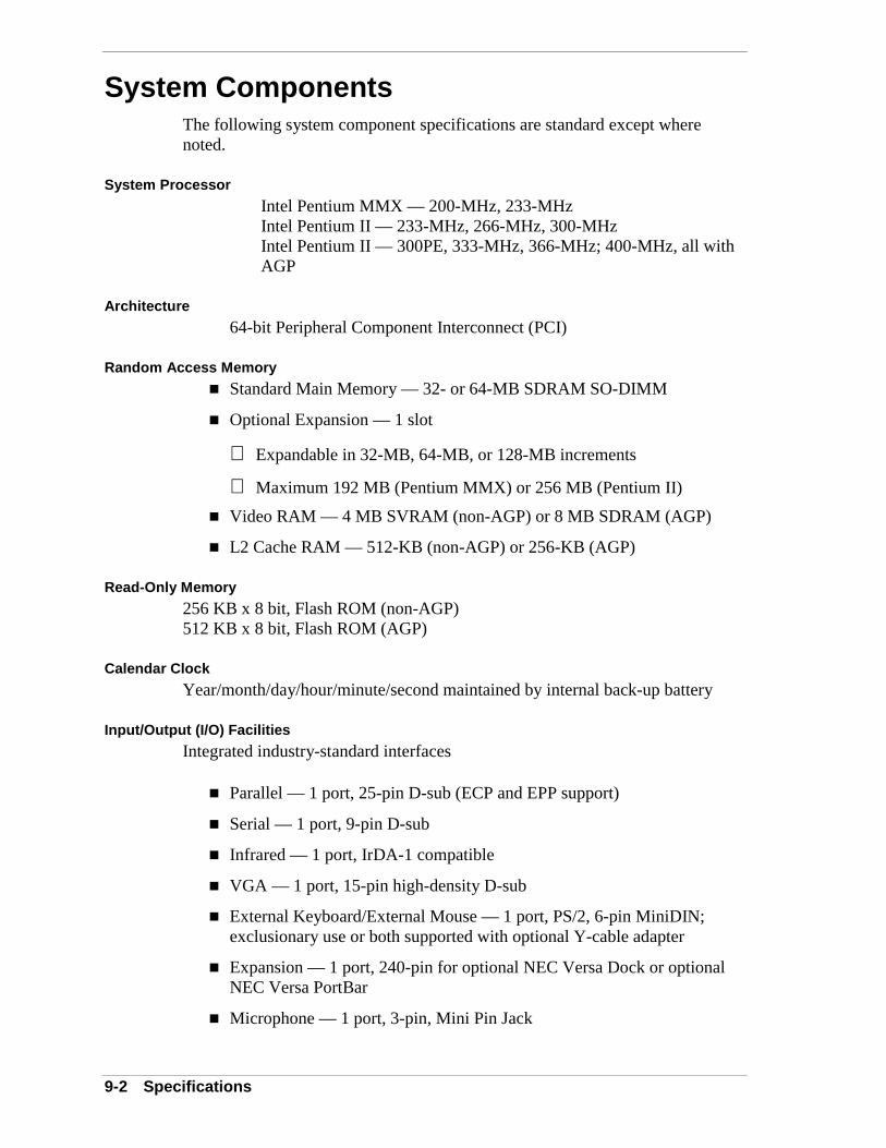
9-2 Specifications
System ComponentsThe following system component specifications are standard except wherenoted.
System Processor
Intel Pentium MMX — 200-MHz, 233-MHzIntel Pentium II — 233-MHz, 266-MHz, 300-MHzIntel Pentium II — 300PE, 333-MHz, 366-MHz; 400-MHz, all withAGP
Architecture
64-bit Peripheral Component Interconnect (PCI)
Random Access Memory
! Standard Main Memory — 32- or 64-MB SDRAM SO-DIMM
! Optional Expansion — 1 slot
Expandable in 32-MB, 64-MB, or 128-MB increments
Maximum 192 MB (Pentium MMX) or 256 MB (Pentium II)
! Video RAM — 4 MB SVRAM (non-AGP) or 8 MB SDRAM (AGP)
! L2 Cache RAM — 512-KB (non-AGP) or 256-KB (AGP)
Read-Only Memory
256 KB x 8 bit, Flash ROM (non-AGP)512 KB x 8 bit, Flash ROM (AGP)
Calendar Clock
Year/month/day/hour/minute/second maintained by internal back-up battery
Input/Output (I/O) Facilities
Integrated industry-standard interfaces
! Parallel — 1 port, 25-pin D-sub (ECP and EPP support)
! Serial — 1 port, 9-pin D-sub
! Infrared — 1 port, IrDA-1 compatible
! VGA — 1 port, 15-pin high-density D-sub
! External Keyboard/External Mouse — 1 port, PS/2, 6-pin MiniDIN;exclusionary use or both supported with optional Y-cable adapter
! Expansion — 1 port, 240-pin for optional NEC Versa Dock or optionalNEC Versa PortBar
! Microphone — 1 port, 3-pin, Mini Pin Jack

Specifications 9-3
! Stereo Headphones/Line-out — 1 port, 3-pin, Mini Pin Jack, .5 watts perchannel
! Stereo Line-In — 1 port, 3-pin, Mini Pin Jack
! TV Out
1 port; 2-pin RCA Jack
1 port, 7-pin S-Video Jack
! DC In — 1 port, for AC adapter cable
! USB port — 1 port, 6 pin
Speakers
Two built-in, 1.4 watts (W) each with a maximum 3W output
! 16-bit stereo, 48 KHz
! Sound BlasterPRO compatible
! MIDI Roland: MPU401, UART Mode compatible
! ESS Maestro2E (PCI Audio) + ESS 1918 (non-AGP) or ESS 1920 (AGP)(AC97 Link)
PC Card Slots
! Two 32-bit card slots for two Type II PC cards or one Type III PC card,5 V or 3.3 V interface
! 32-bit CardBus support
LCD Panel
The LCD panel varies, depending on the model.
! 12.1-inch high resolution active matrix Thin Film Transistor (TFT),Super Video Graphics Array (SVGA) color display
Resolution — 800 x 600
Colors — 16.8 Million, max
! 13.3-inch high resolution active matrix Thin Film Transistor (TFT),Extended Graphics Array (XGA) color display
Resolution — 1024 x 768
Colors — 16.8 Million, max
! 14.1-inch high resolution active matrix Thin Film Transistor (TFT),Extended Graphics Array (XGA) color display
Resolution — 1024 x 768
Colors — 16.8 Million, max
9-4 Specifications
Keyboard
Membrane 85 keys (both U.S. and International) with standard QWERTY-keylayout (International keyboards are country-specific)
! Function keys — 12 keys
! Cursor Control keys — 4 keys; arrow keys arranged in inverted T layout
! Numeric keypad — embedded
! Fn key — function key for ROM-based key functions
! Stroke — 3 mm
Diskette Drive
! Size — 3.5-inch
! Capacity — 1.44 MB (formatted), 2 MB (unformatted)
! Transfer Rate — 250 to 500 K/bps
! Interleave 1:1
! Controller — NS PC87338VJG (non-AGP) or NS PC97338VJG (AGP)
SuperDisk™ Drive
! Formatted Capacity:
Optical diskette — 120 MB
High Density floppy diskette — 1.44 MB
Double Density floppy diskette — 720 KB
! Data Transfer Rate
120-MB: 680 KB/S (max)
1.44-MB: 150 KB/S (max)
720-KB: 75 KB/S (max)
! Track to track seek rate
120-MB: 20ms (typ)
1.44-MB/720-KB: 25ms (typ)
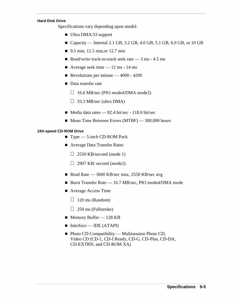
Specifications 9-5
Hard Disk Drive
Specifications vary depending upon model:
! Ultra DMA/33 support
! Capacity — Internal 2.1 GB, 3.2 GB, 4.0 GB, 5.1 GB, 6.0 GB, or 10 GB
! 9.5 mm, 12.5 mm,or 12.7 mm
! Read/write track-to-track seek rate — 3 ms - 4.5 ms
! Average seek time — 12 ms - 14 ms
! Revolutions per minute — 4000 - 4200
! Data transfer rate
16.6 MB/sec (PIO mode4/DMA mode2)
33.3 MB/sec (ultra DMA)
! Media data rates — 82.4 bit/sec - 118.0 bit/sec
! Mean Time Between Errors (MTBF) — 300,000 hours
24X-speed CD-ROM Drive
! Type — 5-inch CD-ROM Pack
! Average Data Transfer Rates
2550 KB/second (mode 1)
2907 KB/ second (mode2)
! Read Rate — 3600 KB/sec max, 2550 KB/sec avg
! Burst Transfer Rate — 16.7 MB/sec, PIO mode4/DMA mode
! Average Access Time
120 ms (Random)
250 ms (Fullstroke)
! Memory Buffer — 128 KB
! Interface — IDE (ATAPI)
! Photo CD Compatibility — Multisession Photo CD,Video CD (CD-1, CD-I Ready, CD-G, CD-Plus, CD-DA,CD-EXTRN, and CD-ROM XA)
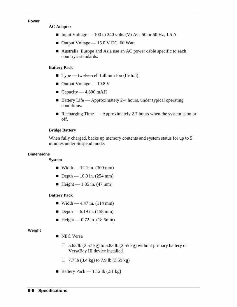
9-6 Specifications
PowerAC Adapter
! Input Voltage — 100 to 240 volts (V) AC, 50 or 60 Hz, 1.5 A
! Output Voltage — 15.0 V DC, 60 Watt
! Australia, Europe and Asia use an AC power cable specific to eachcountry's standards.
Battery Pack
! Type — twelve-cell Lithium Ion (Li-Ion)
! Output Voltage — 10.8 V
! Capacity — 4,800 mAH
! Battery Life — Approximately 2-4 hours, under typical operatingconditions.
! Recharging Time —- Approximately 2.7 hours when the system is on oroff.
Bridge Battery
When fully charged, backs up memory contents and system status for up to 5minutes under Suspend mode.
DimensionsSystem
! Width — 12.1 in. (309 mm)
! Depth — 10.0 in. (254 mm)
! Height — 1.85 in. (47 mm)
Battery Pack
! Width — 4.47 in. (114 mm)
! Depth — 6.19 in. (158 mm)
! Height — 0.72 in. (18.5mm)
Weight
! NEC Versa
5.65 lb (2.57 kg) to 5.83 lb (2.65 kg) without primary battery orVersaBay III device installed
7.7 lb (3.4 kg) to 7.9 lb (3.59 kg)
! Battery Pack — 1.12 lb (.51 kg)

Specifications 9-7
Recommended Environment
Operation
! Temperature — 41°F to 95°F (5°C to 35°C)
! Relative Humidity — 20% to 80% (Noncondensing)
Storage
! Temperature — -4°F to 104°F (-20°C to 40°C)
! Relative Humidity — 20% to 80% (Noncondensing)
Pin AssignmentsKeyboard/Mouse Connectors
Pin Signal
1 Keyboard Data
2 Mouse Data
3 Ground
4 +5V
5 Keyboard Clock
6 Mouse Clock
Serial Port Connector Pin Assignments
Pin Signal
1 Data Carrier
2 Receive Data
3 Transmit Data
4 Data Terminal Ready
5 Ground
6 Data Set Ready
7 Request to Send
8 Clear to Send
9 Ring Indicator
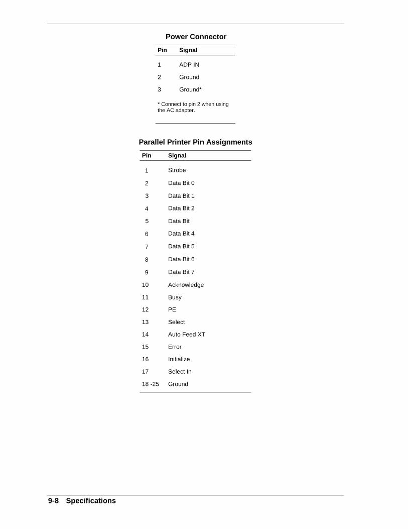
9-8 Specifications
Power Connector
Pin Signal
1 ADP IN
2 Ground
3 Ground*
* Connect to pin 2 when usingthe AC adapter.
Parallel Printer Pin Assignments
Pin Signal
1 Strobe
2 Data Bit 0
3 Data Bit 1
4 Data Bit 2
5 Data Bit
6 Data Bit 4
7 Data Bit 5
8 Data Bit 6
9 Data Bit 7
10 Acknowledge
11 Busy
12 PE
13 Select
14 Auto Feed XT
15 Error
16 Initialize
17 Select In
18 -25 Ground
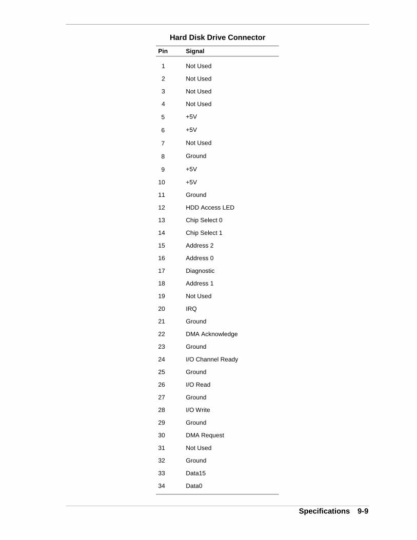
Specifications 9-9
Hard Disk Drive Connector
Pin Signal
1 Not Used
2 Not Used
3 Not Used
4 Not Used
5 +5V
6 +5V
7 Not Used
8 Ground
9 +5V
10 +5V
11 Ground
12 HDD Access LED
13 Chip Select 0
14 Chip Select 1
15 Address 2
16 Address 0
17 Diagnostic
18 Address 1
19 Not Used
20 IRQ
21 Ground
22 DMA Acknowledge
23 Ground
24 I/O Channel Ready
25 Ground
26 I/O Read
27 Ground
28 I/O Write
29 Ground
30 DMA Request
31 Not Used
32 Ground
33 Data15
34 Data0
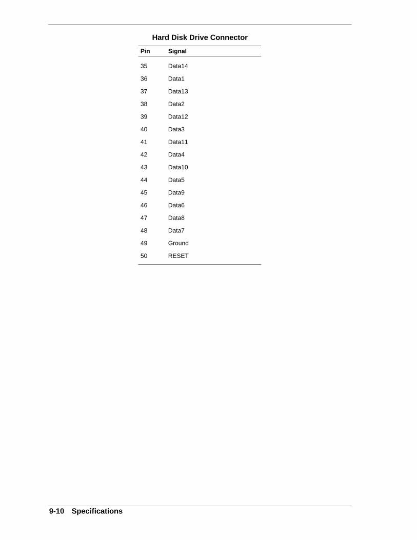
9-10 Specifications
Hard Disk Drive Connector
Pin Signal
35 Data14
36 Data1
37 Data13
38 Data2
39 Data12
40 Data3
41 Data11
42 Data4
43 Data10
44 Data5
45 Data9
46 Data6
47 Data8
48 Data7
49 Ground
50 RESET
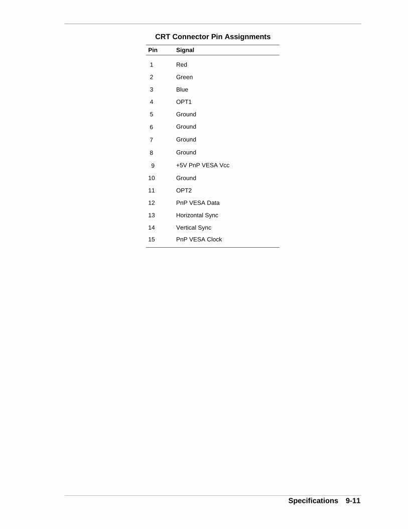
Specifications 9-11
CRT Connector Pin Assignments
Pin Signal
1 Red
2 Green
3 Blue
4 OPT1
5 Ground
6 Ground
7 Ground
8 Ground
9 +5V PnP VESA Vcc
10 Ground
11 OPT2
12 PnP VESA Data
13 Horizontal Sync
14 Vertical Sync
15 PnP VESA Clock
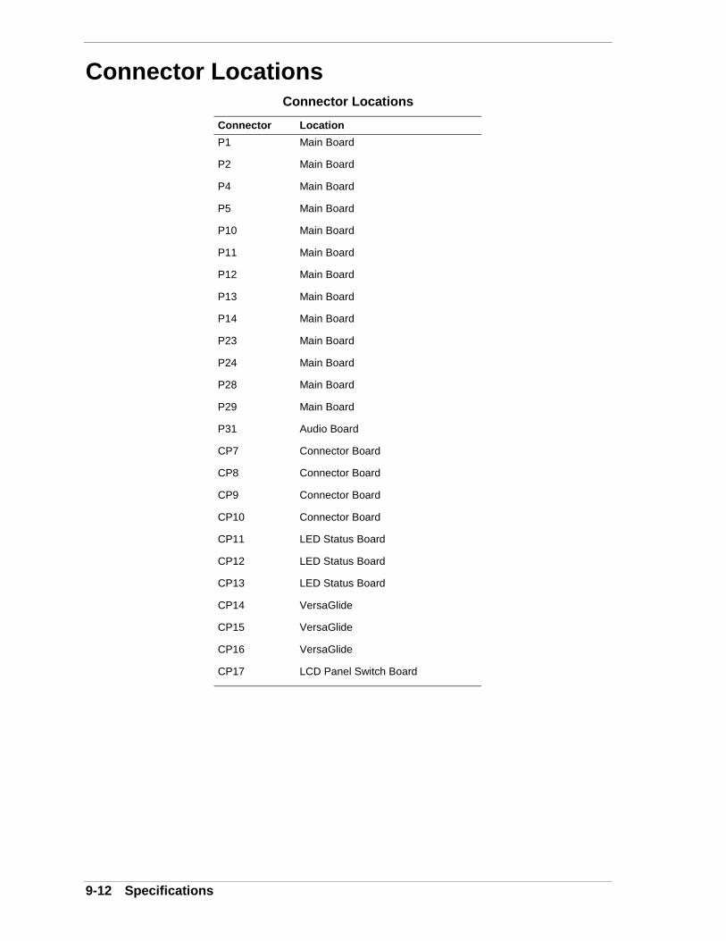
9-12 Specifications
Connector LocationsConnector Locations
Connector Location
P1 Main Board
P2 Main Board
P4 Main Board
P5 Main Board
P10 Main Board
P11 Main Board
P12 Main Board
P13 Main Board
P14 Main Board
P23 Main Board
P24 Main Board
P28 Main Board
P29 Main Board
P31 Audio Board
CP7 Connector Board
CP8 Connector Board
CP9 Connector Board
CP10 Connector Board
CP11 LED Status Board
CP12 LED Status Board
CP13 LED Status Board
CP14 VersaGlide
CP15 VersaGlide
CP16 VersaGlide
CP17 LCD Panel Switch Board
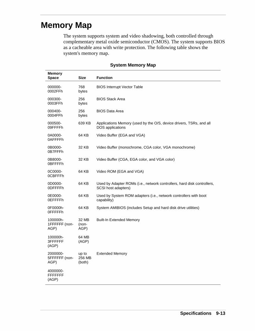
Specifications 9-13
Memory MapThe system supports system and video shadowing, both controlled throughcomplementary metal oxide semiconductor (CMOS). The system supports BIOSas a cacheable area with write protection. The following table shows thesystem's memory map.
System Memory Map
MemorySpace Size Function
000000-0002FFh
768bytes
BIOS Interrupt Vector Table
000300-0003FFh
256bytes
BIOS Stack Area
000400-0004FFh
256bytes
BIOS Data Area
000500-09FFFFh
639 KB Applications Memory (used by the O/S, device drivers, TSRs, and allDOS applications
0A0000-0AFFFFh
64 KB Video Buffer (EGA and VGA)
0B0000-0B7FFFh
32 KB Video Buffer (monochrome, CGA color, VGA monochrome)
0B8000-0BFFFFh
32 KB Video Buffer (CGA, EGA color, and VGA color)
0C0000-0CBFFFh
64 KB Video ROM (EGA and VGA)
0D0000-0DFFFFh
64 KB Used by Adapter ROMs (i.e., network controllers, hard disk controllers,SCSI host adapters)
0E0000-0EFFFFh
64 KB Used by System ROM adapters (i.e., network controllers with bootcapability)
0F0000h-0FFFFFh
64 KB System AMIBIOS (includes Setup and hard disk drive utilities)
100000h-1FFFFFF (non-AGP)
100000h-3FFFFFF(AGP)
32 MB(non-AGP)
64 MB(AGP)
Built-In Extended Memory
2000000-5FFFFFF (non-AGP)
4000000-FFFFFFF(AGP)
up to256 MB(both)
Extended Memory

9-14 Specifications
Interrupt ControllersUsing interrupts, hardware can request software services. If non-Plug and Playsoftware is being used, the interrupt may need to be moved for softwareapplication or driver compatibility. Some interrupts cannot be moved. Fifteeninterrupts can be used with a cascade connection of 8259INTC x 2. The tableshows default interrupt level assignments 0 through 15, in order of decreasingpriority.
System Interrupt Controllers
ControllerMaster/Slave Priority Name Device
Master 0 IRQ00 System Timer 1
Master 1 IRQ01 Keyboard
Master 2 IRQ02 Programmable Controller
Slave 3 IRQ08 Real-time Clock
Slave 4 IRQ09 USB Port
Slave 5 IRQ10 PC Card Bus Controller/Video (AGP)
Slave 6 IRQ11 VersaBay in Versa Dock
Slave 7 IRQ12 PS/2 Mouse/NEC VersaGlide
Slave 8 IRQ13 Math Coprocessor (built into CPU)
Slave 9 IRQ14 Hard Disk Controller 1
Slave 10 IRQ15 VersaBay III
Master 11 IRQ03 Infrared Port, when enabled
Master 12 IRQ04 Serial Port
Master 13 IRQ05 Sound/PC CardBus Controller (AGP)
Master 14 IRQ06 Diskette Drive Controller
Master 15 IRQ07 Parallel Port
Glossary 1
Glossary
A
applications programs Software designed to perform specific functions, like solving business ormathematical problems.
AC Adapter A device that connects an NEC Versa portable computer and an AC wall outlet toprovide AC power for running the system or recharging the battery.
AGP Advanced Graphics Port is an interface specification designed for the throughputdemands of 3D graphics. AGP introduces a point-to-point channel allowing thegraphics controller direct access to main memory, increases bandwidth to266-MBps, and supports throughputs of 533-MBps and 1.07-GBps.
B
base RAM Area of system memory between 0 and 640 kilobytes available to the user foroperating system and application programs.
BIOS Basic Input Output System. A collection of primitive computer routines, usuallyburnt into ROM, that controls the real-time clock, keyboard, disk drives, videodisplay, and other peripheral devices.
bit Binary digit. The smallest unit of computer data.
bits per second (bps) A unit of transmission. Also called baud rate.
board Printed circuit board. Board onto which computer components are soldered and thinwires are printed to connect the components.
boot To start up a computer. See cold boot and warm boot.
bus An electronic circuit within a computer used for transmitting data or electricalpower from one device to another.
byte Group of eight contiguous bits.
2 Glossary
C
clock Electronic timer used to synchronize computer operations.
CMOS Complementary Metal Oxide Semiconductor. A chip that contains nonvolatilememory in the NEC Versa. CMOS is backed up by an internal lithium battery thatpreserves clock/calendar data and system configuration parameters stored inCMOS.
cold boot Process of starting up the computer by turning on the power. If power is already on,the process means to turn off the computer and turn it on again. A cold bootreinitializes all devices.
crt Cathode-Ray Tube. A type of display screen used in desktop monitors. It forms thescreen image using tiny dots called pixels. See also LCD.
cursor A movable image on the display screen that indicates where the next entered dataappears.
D
diskette A thin flexible platter coated with a magnetic material for storing information.
diskette drive A magnetic drive that writes on and retrieves data from a diskette.
DSTN Double-Scan Super-Twisted Nematic. A type of technology used in some NECVersa LCD screen displays.
E
enhanced VGA A video interface that offers more colors or higher resolution than VGA.
extended RAM The area of RAM above the first megabyte of memory in the system available forenhancing system performance.

Glossary 3
F
function key The set of keys on the keyboard (usually F1 through F12) that let you get help anderror message information or quickly select frequently used commands.
H
hard disk A rigid magnetic storage device that provides fast access to stored data.
hardware The electrical and mechanical parts from which a computer is made.
hertz (Hz) A unit of frequency equal to one cycle per second.
hot key Combination of two or three keys (such as Ctrl-Alt-Del ) that you presssimultaneously for a particular function.
I
input /output (I/O) The process of transferring data between the computer and external devices.
IDE Intelligent Drive Electronics. A hard disk drive type that has controller electronicsbuilt into the drive and delivers high throughput.
interface A connection that enables two devices to communicate.
interrupt A special control signal from an I/O device that diverts the attention of themicroprocessor from the program to a special address.
K
kilobyte (KB) 1024 bytes.
L
LAN Local Area Network.
4 Glossary
LCDLiquid Crystal Display. An LCD consists of a thin sandwich of two glass plateswith sealed edges, containing nematic liquid-crystal material that forms the screenimage. The NEC Versa displays are LCD type.
load To copy a program into the computer's memory from a storage device.
M
megabyte (MB) 1,048,576 bytes.
memory Electronic storage area in a computer that retains information and programs. Acomputer has two types of memory — read-only memory (ROM) and randomaccess memory (RAM).
menu A video display of programs or options.
microprocessor A semiconductor central processing unit that is the principal component of amicrocomputer. Usually contained on a single chip that includes an arithmetic logicunit, control logic, and control-memory unit.
mode A method of operation; for example, the NEC Versa operates in either normal orpower-saving modes.
modem MOdulator-DEModulator. A device that links computers over a telephone line.
N
nonvolatile memory Storage media that retains its data when system power is turned off. Nonvolatilememory in the NEC Versa is a complementary metal oxide semiconductor (CMOS)chip which is backed up by an internal battery. The backup batterypreserves the clock/calendar data and system configuration parameters stored inCMOS. See volatile memory.
O
operating system Set of programs that manage the overall operation of the computer.
overwrite Storing information at a location where information is already stored, thusdestroying the original information.
Glossary 5
P
page A type of message transmission in which a message is sent or received via modemto a paging device from a computer (with paging communications software) ortelephone.
parallel interface Interface that communicates eight bits at a time.
parallel printer A printer with a parallel interface.
parameter A characteristic of a device or system.
password A string of characters that the user must enter before the system allows access orsystem privileges.
PCMCIA A credit card sized peripheral interface standard for portable devices. Types ofPCMCIA cards currently offered by major vendors include fax/modems, LAN,storage cards, and wireless communications devices.
peripheralInput or output device not under direct computer control. A printer is a peripheraldevice.
pixels Picture elements. Tiny dots that make up a screen image.
port Provides the means for an interface between the microprocessor and externaldevices. A cable connector is usually plugged into the port to attach the device tothe computer.
processor In a computer, a functional unit that interprets and executes instructions.
prompt A special symbol indicating the beginning of an input line. Also a message thatappears on the screen indicating that the user must take a certain action.
Q
QWERTY The QWERTY keyboard, designed in the 1800s for mechanical typewriters, refersto the first six keys (QWERTY) on the top row of letters on the standard keyboard.
6 Glossary
R
RAM Random Access Memory. A storage device into which data is entered and fromwhich data is retrieved in a nonsequential manner.
read To extract data from a storage device such as a diskette.
ROM Read-Only Memory. Memory in which stored data cannot be modified by the userexcept under special conditions.
reset The process of returning a device to zero or to an initial or arbitrarily selectedcondition.
resolution The degree of screen image clarity. Video display resolution is determined by thenumber of pixels on the screen. Resolution is usually specified in pixels by scanlines, for example, 640 by 480. See pixels.
RS-232C Standard interface for serial devices.
S
scanner An optical device that reads printed material and converts it to a computer screenimage.
serial interface An interface that communicates information one bit at a time.
serial printer A printer with a serial interface.
software Programs that run on a computer, such as operating systems, word processors, andspreadsheets.
super video graphics array (SVGA) A color bit-mapped graphics display standard, that provides a resolution of 1024x768 with up to 256 colors displayed simultaneously.
system board The main printed circuit board inside the system unit into which other boards andmajor chip components, such as the system microprocessor, are connected.

Glossary 7
T
TFT Thin Film Transistor. A type of NEC Versa LCD color screen that supports 256colors and provides exceptional screen display.
V
VersaGlideA small, touch-sensitive pad used as a pointing device on your NEC Versanotebook computer. With the VersaGlide, you can move your finger along the padto move the cursor or simulate a mouse click by tapping the pad.
VGA Video Graphics Array. Graphics technology that supports up to 256 K colors and agraphics resolution of 640 by 480 pixels.
volatile memory Storage media that loses its data when system power is turned off. Standardmemory and memory that you add to the NEC Versa are volatile memory. Seenonvolatile memory.
W
warm boot Process of resetting the computer without turning off the power through keyboardinput (pressing Ctrl , Alt , and Del keys simultaneously) or the reset button. Thesystem returns to an initial or arbitrarily selected condition.
write To record or store information to a storage device.
Index-1
AAC adapter, 2-2
using, 2-2AC outlet, 2-3AC power cable
types, 2-3AC power port, 1-7Adapter kit, 2-10Application and Driver CD, 2-27
using, 2-27Automatic Save to File, 2-19
BBackup system disk, 6-2Base unit, 1-5Battery
determining status, 2-6handling, 2-7recharging precautions, 2-10removing, 1-12when to change, 2-6
Battery charging LEDs, 1-6Battery pack, 1-12
precautions, 2-9using, 2-4
Battery status, 2-4BBS, 8-5BIOS setup, 2-11BIOS setup utility
advanced CMOS setup, 2-17checking system parameters, 2-14looking at screens, 2-13main menu, 2-12other options, 2-21save to file, 2-22standard CMOS setup, 2-16using keys, 2-13
Boot device setup, 2-19Bridge battery, 1-13, 2-11Brightness control, 1-3
CCD-ROM drive, 1-13Cleaning
internal components, 6-2outer surface, 6-2
CMOS battery, 1-13, 2-10Connecting the AC adapter, 2-3
Control panel, 1-4Custom settings, power management, 2-18
DDimensions
battery pack, 9-6system, 9-6
Dip switch settings, 3-7Diskette drive, 1-13Diskette drives, 2-17Docking port, 1-7Docking Station drives, 2-17
EEntering BIOS setup, 2-11Expansion port, 1-7
FFile bay, 1-10
HHandling battery packs, 6-3Hard disk drive, 1-13Headphones, 1-10Height adjustment feet, 1-12
IInternal hard disk drive, 2-17Internal mouse, 2-17Interrupt Controllers, 9-14IR port, 1-8, 2-20
enabling, 2-31IRQs, 9-14
KKensington Lock, 1-10Keyboard panel, 1-5Keyboard/mouse connectors, 9-7
LLCD panel features, 1-3LCD panel view expansion, 2-17LCD status bar, 1-4Line-In, 1-10Lithium-Ion battery, 2-10Low battery power, 1-12, 2-4
MMain battery, 2-10Maintaining LCD quality, 6-4
Index
Index-2
Memory Map, 9-13Microphone, 1-4, 1-10Monitor port, 1-7Mouse port, 1-8
NNEC CSD
bulletin board, 8-5Customer Assistance Center, 8-7email/fax, 8-5FTP site, 8-3support services, 8-7web site, 8-2
NEC CSD utilities, 2-25NEC Customize, 2-25NEC Versa disassembly sequence, 3-2NEC VersaBay, 1-7NEC VersaGlide, 1-5NTSC signal, 1-9
OOptional battery charger, 2-4
PPAL signal, 1-9Panel brightness, 2-19Parallel port, 2-20Parallel port pin assignments, 9-7Parts list (AGP models), 5-6Parts list (Non-AGP models), 5-3Password protection, 2-21Pentium II microprocessor, 1-2Peripheral Component Interconnect (PCI), 1-2Power button, 1-11, 2-18Power management, 2-21
custom settings, 2-18Power management under AC, 2-18Power sources, 2-2Power Status LED, 1-6Powering on, 2-4Power-on self test (POST), 2-11PS/2 Hot Swap, 2-17
QQuick troubleshooting, 7-2
RRecharging the battery, 2-4Recommended operating environment, 9-7Remote power on, 2-19Replacing the battery pack, 2-7, 3-2Resume Signal, 2-19
SSave to file
feature, 2-22SECAM signal, 1-9Serial port, 1-7, 2-20Services and Support
contact information, 8-2Servicing the system
required tools, 3-2Setting boot devices, 2-20Setting system parameters, 2-14
peripherals, 2-20power savings, 2-18
Smart switch, 1-11Software applications, 2-27Specifications
calendar clock, 9-2CD-ROM drive, 9-5diskette drive, 9-4hard disk drive, 9-5input/output facilities, 9-2keyboard, 9-4PC card slots, 9-3power, 9-6Random Access Memory, 9-2Read-Only Memory, 9-2speakers, 9-3
Stereo speakers, 1-5Suspend mode, 2-19Suspend warning tone, 2-19Switch settings, 3-7
changing, 3-8System date, 2-16System features
back, 1-7bottom, 1-12front, 1-3left, 1-8right, 1-10
System security setup, 2-17System software, 2-27System time, 2-17
TTroubleshooting
helpful questions, 7-4TV signal types, 1-9
UUpdating the BIOS, 2-22USB controller, 2-20USB port, 1-9Using the AC adapter, 2-2
Index-3
Using the battery pack, 2-4
VVersaBay III
removing a device, 1-12Video out type, 2-17Volume control, 1-10
WWake up, suspend alarm, 2-19Weight
battery pack, 9-6system, 9-6
YY-cable adapter, 1-8
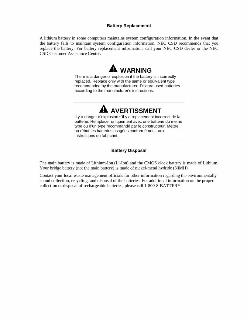
Battery Replacement
A lithium battery in some computers maintains system configuration information. In the event thatthe battery fails to maintain system configuration information, NEC CSD recommends that youreplace the battery. For battery replacement information, call your NEC CSD dealer or the NECCSD Customer Assistance Center.
! WARNINGThere is a danger of explosion if the battery is incorrectlyreplaced. Replace only with the same or equivalent typerecommended by the manufacturer. Discard used batteriesaccording to the manufacturer’s instructions.
.
! AVERTISSMENTIl y a danger d’explosion s’il y a replacement incorrect de labatterie. Remplacer uniquement avec une batterie du mêmetype ou d’un type recommandé par le constructeur. Mettreau rébut les batteries usagées conformément auxinstructions du fabricant.
Battery Disposal
The main battery is made of Lithium-Ion (Li-Ion) and the CMOS clock battery is made of Lithium.Your bridge battery (not the main battery) is made of nickel-metal hydride (NiMH).
Contact your local waste management officials for other information regarding the environmentallysound collection, recycling, and disposal of the batteries. For additional information on the propercollection or disposal of rechargeable batteries, please call 1-800-8-BATTERY.
(For United States Use Only)
Federal Communications CommissionRadio Frequency Interference Statement
! WARNINGChanges or modifications to this unit not expressly approved by the partyresponsible for compliance could void the user’s authority to operate theequipment.
Note: This is a Class B Digital Device. This equipment has been tested andfound to comply with the limits for a Class B digital device, pursuant to Part 15 ofthe FCC Rules. These limits are designed to provide reasonable protection againstharmful interference in a residential installation. This equipment generates, usesand can radiate radio frequency energy and, if not installed and used in accordancewith the instructions, may cause harmful interference to radio communications.
However, there is no guarantee that interference will not occur in a particular installation. If this equipment does causeharmful interference to radio or television reception, which can be determined by turning the equipment off and on, theuser is encouraged to try to correct the interference by one or more of the following measures.
� Reorient or relocate the receiving antenna.
� Increase the separation between the equipment and receiver.
� Connect the equipment to an outlet on a circuit different from the one to which the receiver is connected.
To meet FCC standards, shielded cables and power cords are required to connect this device to a personal computer orother Class B certified device.
Canadian Department of Communications Compliance StatementThis equipment does not exceed Class B limits per radio noise emissions or digital apparatus, set out in the Radio interference Regulationof the Canadian Department of Communications.
Avis de conformité aux normes du ministere des communications du CanadaCet equipment ne depasse pas les limites de Classe B d'émission de bruits radioelectriques pour les appareill numerique, lelles queprescribes per le Reglement sur le brouillage radioélectrique elebil por le minisieredes Communications du Canada.
European Community Directive Conformance StatementThis product is in conformity with the protection requirements of EC Council Directive 89/336/EEC on the approximation of laws of theMember States relating to electro-magnetic compatibility. This product satisfied the Class B limits of EN 55022.
NEC Computer Systems DivisionPackard Bell NEC, Inc.
1 Packard Bell WaySacramento, California 95828-0903
1-916-388-0101

NEC Computer Systems Division Packard Bell NEC, Inc. 1 Packard Bell Way Sacramento, CA 95828-0903
819-200064-0003/99
%�&(����#%�&(����#!!(���(���