neets module 01 - introduction to matter, energy, and direct current
TRANSCRIPT

8/6/2019 NEETS MODULE 01 - Introduction to Matter, Energy, And Direct Current
http://slidepdf.com/reader/full/neets-module-01-introduction-to-matter-energy-and-direct-current 1/278
Navy Electricity and
Electronics TrainingSeries
Module 1—Introduction to Matter,
Energy, and Direct Current
NAVEDTRA 14173
NONRESIDENTTRAINING
COURSE
DISTRIBUTION STATEMENT A: Approved for public release; distribution is unlimited.
Notice: NETPDTC is no longer responsible for the content accuracy of the NRTCs.
For content issues, contact the servicing Center of Excellence: Center for Surface
Combat System (CSCS); (540) 284-1061 or DSN: 249-1061.

8/6/2019 NEETS MODULE 01 - Introduction to Matter, Energy, And Direct Current
http://slidepdf.com/reader/full/neets-module-01-introduction-to-matter-energy-and-direct-current 2/278
Sailor’s Creed
“I am a United States Sailor.
I will support and defend theConstitution of the United States ofAmerica and I will obey the ordersof those appointed over me.
I represent the fighting spirit of theNavy and those who have gonebefore me to defend freedom anddemocracy around the world.
I proudly serve my country’s Navy
combat team with honor, courageand commitment.
I am committed to excellence andthe fair treatment of all.”
DISTRIBUTION STATEMENT A: Approved for public release; distribution is unlimited.
8/6/2019 NEETS MODULE 01 - Introduction to Matter, Energy, And Direct Current
http://slidepdf.com/reader/full/neets-module-01-introduction-to-matter-energy-and-direct-current 3/278
PREFACE
By enrolling in this self-study course, you have demonstrated a desire to improve yourself and the Navy.Remember, however, this self-study course is only one part of the total Navy training program. Practicalexperience, schools, selected reading, and your desire to succeed are also necessary to successfully round
out a fully meaningful training program.
COURSE OVERVIEW: Subjects of matter, energy, electricity, batteries, and direct current are presentedto give the student background information on topics that may be encountered in daily work.
THE COURSE : This self-study course is organized into subject matter areas, eachcontaining learning objectives to help you determine what you should learn along withtext and illustrations to help you understand the information. The subject matter reflectsday-to-day requirements and experiences of personnel in the rating or skill area. It also reflects guidance
provided by Enlisted Community Managers (ECMs) and other senior personnel, technical references,instructions, etc., and the occupational standards, which are listed in the Manual of Navy Enlisted
Manpower Personnel Classifications and Occupational Standards , NAVPERS 18068, found on line at
https://buperscd.technology.navy.mil /bup_updt/upd_CD/BUPERS/enlistedManOpen.htm.
THE QUESTIONS: The questions that appear in this course are designed to help you understand thematerial in the text.
VALUE: In completing this course, you will improve your military and professional knowledge.Importantly, it can also help you study for the Navy-wide advancement in rate examination. If you arestudying and discover a reference in the text to another publication for further information, look it up.
1998 Edition Prepared by ETCS(SW) Donnie Jones
Corrections and minor modifications prepared in January 2003 by
ETC Jack Weatherford
NAVSUP Logistics Tracking Number
0504-LP-026-8260
i

8/6/2019 NEETS MODULE 01 - Introduction to Matter, Energy, And Direct Current
http://slidepdf.com/reader/full/neets-module-01-introduction-to-matter-energy-and-direct-current 4/278
ii
TABLE OF CONTENTS
CHAPTER PAGE
1. Matter, Energy, and Electricity .............................................................................. 1-1
2. Batteries ................................................................................................................. 2-1
3. Direct Current......................................................................................................... 3-1
APPENDIX
I. Glossary ................................................................................................................. AI-1
II. Laws of Exponents................................................................................................. AII-1
III. Square and Square Roots ....................................................................................... AIII-1
IV.Comparison of Units in Electric and Magnetic Circuits; and Carbon Resistor
Size Comparison by Wattage Rating ..................................................................... AIV-1
V. Useful Formulas for I.C. Circuits........................................................................... AV-1
Assignments follow Appendix V.
8/6/2019 NEETS MODULE 01 - Introduction to Matter, Energy, And Direct Current
http://slidepdf.com/reader/full/neets-module-01-introduction-to-matter-energy-and-direct-current 5/278
NAVY ELECTRICITY AND ELECTRONICS TRAININGSERIES
The Navy Electricity and Electronics Training Series (NEETS) was developed for use by personnel in
many electrical- and electronic-related Navy ratings. Written by, and with the advice of, seniortechnicians in these ratings, this series provides beginners with fundamental electrical and electronic
concepts through self-study. The presentation of this series is not oriented to any specific rating structure,
but is divided into modules containing related information organized into traditional paths of instruction.
The series is designed to give small amounts of information that can be easily digested before advancing
further into the more complex material. For a student just becoming acquainted with electricity or
electronics, it is highly recommended that the modules be studied in their suggested sequence. While
there is a listing of NEETS by module title, the following brief descriptions give a quick overview of how
the individual modules flow together.
Module 1, Introduction to Matter, Energy, and Direct Current , introduces the course with a short history
of electricity and electronics and proceeds into the characteristics of matter, energy, and direct current
(dc). It also describes some of the general safety precautions and first-aid procedures that should be
common knowledge for a person working in the field of electricity. Related safety hints are located
throughout the rest of the series, as well.
Module 2, Introduction to Alternating Current and Transformers, is an introduction to alternating current
(ac) and transformers, including basic ac theory and fundamentals of electromagnetism, inductance,
capacitance, impedance, and transformers.
Module 3, Introduction to Circuit Protection, Control, and Measurement, encompasses circuit breakers,
fuses, and current limiters used in circuit protection, as well as the theory and use of meters as electrical
measuring devices.
Module 4, Introduction to Electrical Conductors, Wiring Techniques, and Schematic Reading, presentsconductor usage, insulation used as wire covering, splicing, termination of wiring, soldering, and reading
electrical wiring diagrams.
Module 5, Introduction to Generators and Motors, is an introduction to generators and motors, andcovers the uses of ac and dc generators and motors in the conversion of electrical and mechanical
energies.
Module 6, Introduction to Electronic Emission, Tubes, and Power Supplies, ties the first five modules
together in an introduction to vacuum tubes and vacuum-tube power supplies.
Module 7, Introduction to Solid-State Devices and Power Supplies, is similar to module 6, but it is in
reference to solid-state devices.
Module 8, Introduction to Amplifiers, covers amplifiers.
Module 9, Introduction to Wave-Generation and Wave-Shaping Circuits, discusses wave generation and
wave-shaping circuits.
Module 10, Introduction to Wave Propagation, Transmission Lines, and Antennas, presents the
characteristics of wave propagation, transmission lines, and antennas.
iii

8/6/2019 NEETS MODULE 01 - Introduction to Matter, Energy, And Direct Current
http://slidepdf.com/reader/full/neets-module-01-introduction-to-matter-energy-and-direct-current 6/278
Module 11, Microwave Principles, explains microwave oscillators, amplifiers, and waveguides.
Module 12, Modulation Principles, discusses the principles of modulation.
Module 13, Introduction to Number Systems and Logic Circuits, presents the fundamental concepts of
number systems, Boolean algebra, and logic circuits, all of which pertain to digital computers.
Module 14, Introduction to Microelectronics, covers microelectronics technology and miniature and
microminiature circuit repair.
Module 15, Principles of Synchros, Servos, and Gyros, provides the basic principles, operations,
functions, and applications of synchro, servo, and gyro mechanisms.
Module 16, Introduction to Test Equipment, is an introduction to some of the more commonly used test
equipments and their applications.
Module 17, Radio-Frequency Communications Principles, presents the fundamentals of a radio-
frequency communications system.
Module 18, Radar Principles, covers the fundamentals of a radar system.
Module 19, The Technician ,s Handbook, is a handy reference of commonly used general information,
such as electrical and electronic formulas, color coding, and naval supply system data.
Module 20, Master Glossary, is the glossary of terms for the series.
Module 21, Test Methods and Practices, describes basic test methods and practices.
Module 22, Introduction to Digital Computers, is an introduction to digital computers.
Module 23, Magnetic Recording, is an introduction to the use and maintenance of magnetic recorders and
the concepts of recording on magnetic tape and disks.
Module 24, Introduction to Fiber Optics, is an introduction to fiber optics.
Embedded questions are inserted throughout each module, except for modules 19 and 20, which are
reference books. If you have any difficulty in answering any of the questions, restudy the applicable
section.
Although an attempt has been made to use simple language, various technical words and phrases have
necessarily been included. Specific terms are defined in Module 20, Master Glossary.
Considerable emphasis has been placed on illustrations to provide a maximum amount of information. In
some instances, a knowledge of basic algebra may be required.
Assignments are provided for each module, with the exceptions of Module 19, The Technician
,
s Handbook ; and Module 20, Master Glossary. Course descriptions and ordering information are in
NAVEDTRA 12061, Catalog of Nonresident Training Courses.
iv

8/6/2019 NEETS MODULE 01 - Introduction to Matter, Energy, And Direct Current
http://slidepdf.com/reader/full/neets-module-01-introduction-to-matter-energy-and-direct-current 7/278
Throughout the text of this course and while using technical manuals associated with the equipment you
will be working on, you will find the below notations at the end of some paragraphs. The notations are
used to emphasize that safety hazards exist and care must be taken or observed.
WARNING
AN OPERATING PROCEDURE, PRACTICE, OR CONDITION, ETC., WHICH MAY
RESULT IN INJURY OR DEATH IF NOT CAREFULLY OBSERVED OR
FOLLOWED.
CAUTION
AN OPERATING PROCEDURE, PRACTICE, OR CONDITION, ETC., WHICH MAY
RESULT IN DAMAGE TO EQUIPMENT IF NOT CAREFULLY OBSERVED OR
FOLLOWED.
NOTE
An operating procedure, practice, or condition, etc., which is essential to emphasize.
v

8/6/2019 NEETS MODULE 01 - Introduction to Matter, Energy, And Direct Current
http://slidepdf.com/reader/full/neets-module-01-introduction-to-matter-energy-and-direct-current 8/278
INSTRUCTIONS FOR TAKING THE COURSE
ASSIGNMENTS
The text pages that you are to study are listed atthe beginning of each assignment. Study these pages carefully before attempting to answer thequestions. Pay close attention to tables andillustrations and read the learning objectives.
The learning objectives state what you should beable to do after studying the material. Answeringthe questions correctly helps you accomplish theobjectives.
SELECTING YOUR ANSWERS
Read each question carefully, then select theBEST answer. You may refer freely to the text.The answers must be the result of your ownwork and decisions. You are prohibited from
referring to or copying the answers of others and
from giving answers to anyone else taking thecourse.
SUBMITTING YOUR ASSIGNMENTS
To have your assignments graded, you must be
enrolled in the course with the NonresidentTraining Course Administration Branch at the
Naval Education and Training ProfessionalDevelopment and Technology Center (NETPDTC). Following enrollment, there are
two ways of having your assignments graded:(1) use the Internet to submit your assignmentsas you complete them, or (2) send all theassignments at one time by mail to NETPDTC.
Grading on the Internet: Advantages to
Internet grading are:
• you may submit your answers as soon as
you complete an assignment, and
• you get your results faster; usually by thenext working day (approximately 24 hours).
In addition to receiving grade results for eachassignment, you will receive course completionconfirmation once you have completed all the
assignments. To submit your assignmentanswers via the Internet, go to:
https://courses.cnet.navy.mil
COMPLETION TIME
Courses must be completed within 12 monthsfrom the date of enrollment. This includes timerequired to resubmit failed assignments.
vi
8/6/2019 NEETS MODULE 01 - Introduction to Matter, Energy, And Direct Current
http://slidepdf.com/reader/full/neets-module-01-introduction-to-matter-energy-and-direct-current 9/278
PASS/FAIL ASSIGNMENT PROCEDURES
If your overall course score is 3.2 or higher, youwill pass the course and will not be required to
resubmit assignments. Once your assignments
have been graded you will receive course
completion confirmation.
If you receive less than a 3.2 on any assignmentand your overall course score is below 3.2, youwill be given the opportunity to resubmit failed
assignments. You may resubmit failed
assignments only once. Internet students willreceive notification when they have failed anassignment—they may then resubmit failedassignments on the web site. Internet students
may view and print results for failedassignments from the web site. Students who
submit by mail will receive a failing result letter and a new answer sheet for resubmission of eachfailed assignment.
COMPLETION CONFIRMATION
After successfully completing this course, you
will receive a letter of completion.NAVAL RESERVE RETIREMENT CREDIT
If you are a member of the Naval Reserve, you
may earn retirement points for successfully
completing this course, if authorized under current directives governing retirement of Naval
Reserve personnel. For Naval Reserveretirement, this course is evaluated at 6 points.(Refer to dministrative Procedures for Naval
Reservists on Inactive Duty, BUPERSINST
1001.39, for more information about retirement points.)
STUDENT FEEDBACK QUESTIONS
We value your suggestions, questions, and
criticisms on our courses. If you would like tocommunicate with us regarding this course, we
encourage you, if possible, to use e-mail.
vii

8/6/2019 NEETS MODULE 01 - Introduction to Matter, Energy, And Direct Current
http://slidepdf.com/reader/full/neets-module-01-introduction-to-matter-energy-and-direct-current 10/278
(THIS PAGE IS INTENTIONALLY LEFT BLANK.)
viii

8/6/2019 NEETS MODULE 01 - Introduction to Matter, Energy, And Direct Current
http://slidepdf.com/reader/full/neets-module-01-introduction-to-matter-energy-and-direct-current 11/278
CHAPTER 1
MATTER, ENERGY, AND ELECTRICITY
LEARNING OBJECTIVES
Learning objectives are stated at the beginning of each chapter. These learning objectives serve as a
preview of the information you are expected to learn in the chapter. The comprehensive check questions
are based on the objectives. By successfully completing the NRTC, you indicate that you have met the
objectives and have learned the information. The learning objectives are listed below.
Upon completing this chapter, you will be able to:
1. State the meanings of and the relationship between matter, element, nucleus, compound,
molecule, mixture, atom, electron, proton, neutron, energy, valence, valence shell, and ion.
2. State the meanings of and the relationship between kinetic energy, potential energy, photons,
electron orbits, energy levels, and shells and subshells.
3. State, in terms of valence, the differences between a conductor, an insulator, and a
semiconductor, and list some materials which make the best conductors and insulators.
4. State the definition of static electricity and explain how static electricity is generated.
5. State the meanings of retentivity, reluctance, permeability, ferromagnetism, natural magnet, and
artificial magnet as used to describe magnetic materials.
6. State the Weber and domain theories of magnetism and list six characteristics of magnetic lines of
force (magnetic flux), including their relation to magnetic induction, shielding, shape, and
storage.
7. State, using the water analogy, how a difference of potential (a voltage or an electromotive force)
can exist. Convert volts to microvolts, to millivolts, and to kilovolts.
8. List six methods for producing a voltage (emf) and state the operating principles of and the uses
for each method.
9. State the meanings of electron current, random drift, directed drift, and ampere, and indicate the
direction that an electric current flows.
10. State the relationship of current to voltage and convert amperes to milliamperes and
microamperes.
11. State the definitions of and the terms and symbols for resistance and conductance, and how thetemperature, contents, length and cross-sectional area of a conductor affect its resistance and
conductance values.
12. List the physical and operating characteristics of and the symbols, ratings, and uses for various
types of resistors; use the color code to identify resistor values.
1-1

8/6/2019 NEETS MODULE 01 - Introduction to Matter, Energy, And Direct Current
http://slidepdf.com/reader/full/neets-module-01-introduction-to-matter-energy-and-direct-current 12/278
INTRODUCTION
The origin of the modern technical and electronic Navy stretches back to the beginning of naval
history, when the first navies were no more than small fleets of wooden ships, using wind-filled sails and
manned oars. The need for technicians then was restricted to a navigator and semiskilled seamen who
could handle the sails.
As time passed, larger ships that carried more sail were built. These ships, encouraging exploration
and commerce, helped to establish world trade routes. Soon strong navies were needed to guard these sea
lanes. Countries established their own navies to protect their citizens, commercial ships, and shipping
lanes against pirates and warring nations. With the addition of mounted armament, gunners joined the
ship,s company of skilled or semiskilled technicians.
The advent of the steam engine signaled the rise of an energy source more practical than either wind
and sails or manpower. With this technological advancement, the need for competent operators and
technicians increased.
However, the big call for operators and technicians in the U.S. Navy came in the early part of the
20th century, when power sources, means of communication, modes of detection, and armaments movedwith amazing rapidity toward involved technical development. Electric motors and generators by then had
become the most widely used sources of power. Telephone systems were well established on board ship,
and radio was being used more and more to relay messages from ship to ship and from ship to shore.
Listening devices were employed to detect submarines. Complex optical systems were used to aim large
naval rifles. Mines and torpedoes became highly developed, effective weapons, and airplanes joined the
Navy team.
During the years after World War I, the Navy became more electricity and electronic minded. It was
recognized that a better system of communications was needed aboard each ship, and between the ships,
planes, submarines, and shore installations; and that weaponry advances were needed to keep pace with
worldwide developments in that field. This growing technology carried with it the awareness that an
equally skilled force of technicians was needed for maintenance and service duties.
World War II proved that all of the expense of providing equipment for the fleet and of training
personnel to handle that equipment paid great dividends. The U. S. Navy had the modern equipment and
highly trained personnel needed to defeat the powerful fleets of the enemy.
Today there is scarcely anyone on board a Navy ship who does not use electrical or electronic
equipment. This equipment is needed in systems of electric lighting and power, intercommunications,
radio, radar, sonar, loran, remote metering, weapon aiming, and certain types of mines and torpedoes. The
Navy needs trained operators and technicians in this challenging field of electronics and electricity. It is to
achieve this end that this module, and others like it, are published.
MATTER, ENERGY, AND ELECTRICITY
If there are roots to western science, they no doubt lie under the rubble that was once ancient Greece.
With the exception of the Greeks, ancient people had little interest in the structure of materials. They
accepted a solid as being just that a continuous, uninterrupted substance. One Greek school of thought
believed that if a piece of matter, such as copper, were subdivided, it could be done indefinitely and still
only that material would be found. Others reasoned that there must be a limit to the number of
subdivisions that could be made and have the material still retain its original characteristics. They held
fast to the idea that there must be a basic particle upon which all substances are built. Recent experiments
have revealed that there are, indeed, several basic particles, or building blocks within all substances.
1-2

8/6/2019 NEETS MODULE 01 - Introduction to Matter, Energy, And Direct Current
http://slidepdf.com/reader/full/neets-module-01-introduction-to-matter-energy-and-direct-current 13/278
The following paragraphs explain how substances are classified as elements and compounds, and aremade up of molecules and atoms. This, then, will be a learning experience about protons, electrons,
valence, energy levels, and the physics of electricity.
MATTER
Matter is defined as anything that occupies space and has weight; that is, the weight and dimensions
of matter can be measured. Examples of matter are air, water, automobiles, clothing, and even our own
bodies. Thus, we can say that matter may be found in any one of three states: SOLID, LIQUID, and
GASEOUS.
ELEMENTS AND COMPOUNDS
An ELEMENT is a substance which cannot be reduced to a simpler substance by chemical means.
Examples of elements with which you are in everyday contact are iron, gold, silver, copper, and oxygen.
There are now over 100 known elements. All the different substances we know about are composed of
one or more of these elements.
When two or more elements are chemically combined, the resulting substance is called aCOMPOUND. A compound is a chemical combination of elements which can be separated by chemical
but not by physical means. Examples of common compounds are water which consists of hydrogen and
oxygen, and table salt, which consists of sodium and chlorine. A MIXTURE, on the other hand, is a
combination of elements and compounds, not chemically combined, that can be separated by physical
means. Examples of mixtures are air, which is made up of nitrogen, oxygen, carbon dioxide, and small
amounts of several rare gases, and sea water, which consists chiefly of salt and water.
Q1. What is matter, and in what three states is it found?
Q2. What is an element?
Q3. What is a compound?
Q4. What is the difference between a compound and a mixture?
MOLECULES
A MOLECULE is a chemical combination of two or more atoms, (atoms are described in the next
paragraph). In a compound the molecule is the smallest particle that has all the characteristics of the
compound.
Consider water, for example. Water is matter, since it occupies space and has weight. Depending onthe temperature, it may exist as a liquid (water), a solid (ice), or a gas (steam). Regardless of the
temperature, it will still have the same composition. If we start with a quantity of water, divide this and
pour out one half, and continue this process a sufficient number of times, we will eventually end up with aquantity of water which cannot be further divided without ceasing to be water. This quantity is called a
molecule of water. If this molecule of water divided, instead of two parts of water, there will be one part
of oxygen and two parts of hydrogen (H2O).
ATOMS
Molecules are made up of smaller particles called ATOMS. An atom is the smallest particle of an
element that retains the characteristics of that element. The atoms of one element, however, differ from
1-3

8/6/2019 NEETS MODULE 01 - Introduction to Matter, Energy, And Direct Current
http://slidepdf.com/reader/full/neets-module-01-introduction-to-matter-energy-and-direct-current 14/278
the atoms of all other elements. Since there are over 100 known elements, there must be over 100
different atoms, or a different atom for each element. Just as thousands of words can be made by
combining the proper letters of the alphabet, so thousands of different materials can be made by
chemically combining the proper atoms.
Any particle that is a chemical combination of two or more atoms is called a molecule. The oxygen
molecule consists of two atoms of oxygen, and the hydrogen molecule consists of two atoms of hydrogen.Sugar, on the other hand, is a compound composed of atoms of carbon, hydrogen, and oxygen. These
atoms are combined into sugar molecules. Since the sugar molecules can be broken down by chemical
means into smaller and simpler units, we cannot have sugar atoms.
The atoms of each element are made up of electrons, protons, and, in most cases, neutrons, which arecollectively called subatomic particles. Furthermore, the electrons, protons, and neutrons of one element
are identical to those of any other element. The reason that there are different kinds of elements is that the
number and the arrangement of electrons and protons within the atom are different for the different
elements
The electron is considered to be a small negative charge of electricity. The proton has a positive
charge of electricity equal and opposite to the charge of the electron. Scientists have measured the mass
and size of the electron and proton, and they know how much charge each possesses. The electron and
proton each have the same quantity of charge, although the mass of the proton is approximately 1837
times that of the electron. In some atoms there exists a neutral particle called a neutron. The neutron has a
mass approximately equal to that of a proton, but it has no electrical charge. According to a popular
theory, the electrons, protons, and neutrons of the atoms are thought to be arranged in a manner similar to
a miniature solar system. The protons and neutrons form a heavy nucleus with a positive charge, around
which the very light electrons revolve.
Figure 1-1 shows one hydrogen and one helium atom. Each has a relatively simple structure. The
hydrogen atom has only one proton in the nucleus with one electron rotating about it. The helium atom is
a little more complex. It has a nucleus made up of two protons and two neutrons, with two electrons
rotating about the nucleus. Elements are classified numerically according to the complexity of their
atoms. The atomic number of an atom is determined by the number of protons in its nucleus.
Figure 1-1.—Structures of simple atoms.
In a neutral state, an atom contains an equal number of protons and electrons. Therefore, an atom of
hydrogen—which contains one proton and one electron—has an atomic number of 1; and helium, with
1-4
8/6/2019 NEETS MODULE 01 - Introduction to Matter, Energy, And Direct Current
http://slidepdf.com/reader/full/neets-module-01-introduction-to-matter-energy-and-direct-current 15/278
two protons and two electrons, has an atomic number of 2. The complexity of atomic structure increases
with the number of protons and electrons.
Q5. What is a molecule?
Q6. What are the three types of subatomic particles, and what are their charges?
Energy Levels
Since an electron in an atom has both mass and motion, it contains two types of energy. By virtue of
its motion the electron contains KINETIC ENERGY. Due to its position it also contains POTENTIAL
ENERGY. The total energy contained by an electron (kinetic plus potential) is the factor which
determines the radius of the electron orbit. In order for an electron to remain in this orbit, it must neither
GAIN nor LOSE energy.
It is well known that light is a form of energy, but the physical form in which this energy exists is not
known.
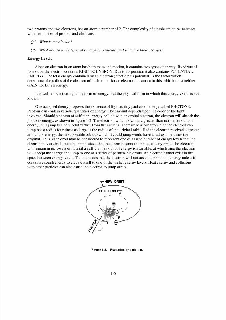
One accepted theory proposes the existence of light as tiny packets of energy called PHOTONS.
Photons can contain various quantities of energy. The amount depends upon the color of the lightinvolved. Should a photon of sufficient energy collide with an orbital electron, the electron will absorb the
photon,s energy, as shown in figure 1-2. The electron, which now has a greater than normal amount of
energy, will jump to a new orbit farther from the nucleus. The first new orbit to which the electron can
jump has a radius four times as large as the radius of the original orbit. Had the electron received a greater
amount of energy, the next possible orbit to which it could jump would have a radius nine times the
original. Thus, each orbit may be considered to represent one of a large number of energy levels that the
electron may attain. It must be emphasized that the electron cannot jump to just any orbit. The electron
will remain in its lowest orbit until a sufficient amount of energy is available, at which time the electron
will accept the energy and jump to one of a series of permissible orbits. An electron cannot exist in the
space between energy levels. This indicates that the electron will not accept a photon of energy unless it
contains enough energy to elevate itself to one of the higher energy levels. Heat energy and collisions
with other particles can also cause the electron to jump orbits.
Figure 1-2.—Excitation by a photon.
1-5

8/6/2019 NEETS MODULE 01 - Introduction to Matter, Energy, And Direct Current
http://slidepdf.com/reader/full/neets-module-01-introduction-to-matter-energy-and-direct-current 16/278
Once the electron has been elevated to an energy level higher than the lowest possible energy level,the atom is said to be in an excited state. The electron will not remain in this excited condition for more
than a fraction of a second before it will radiate the excess energy and return to a lower energy orbit. To
illustrate this principle, assume that a normal electron has just received a photon of energy sufficient to
raise it from the first to the third energy level. In a short period of time the electron may jump back to the
first level emitting a new photon identical to the one it received.
A second alternative would be for the electron to return to the lower level in two jumps; from the
third to the second, and then from the second to the first. In this case the electron would emit two photons,
one for each jump. Each of these photons would have less energy than the original photon which excited
the electron.
This principle is used in the fluorescent light where ultraviolet light photons, which are not visible to
the human eye, bombard a phosphor coating on the inside of a glass tube. The phosphor electrons, in
returning to their normal orbits, emit photons of light that are visible. By using the proper chemicals for
the phosphor coating, any color of light may be obtained, including white. This same principle is also
used in lighting up the screen of a television picture tube.
The basic principles just developed apply equally well to the atoms of more complex elements. In
atoms containing two or more electrons, the electrons interact with each other and the exact path of any
one electron is very difficult to predict. However, each electron lies in a specific energy band and the
orbits will be considered as an average of the electron,s position.
Q7. What is energy of motion called?
Q8. How is invisible light changed to visible light in a fluorescent light?
Shells and Subshells
The difference between the atoms, insofar as their chemical activity and stability are concerned, is
dependent upon the number and position of the electrons included within the atom. How are these
electrons positioned within the atom? In general, the electrons reside in groups of orbits called shells.
These shells are elliptically shaped and are assumed to be located at fixed intervals. Thus, the shells are
arranged in steps that correspond to fixed energy levels. The shells, and the number of electrons required
to fill them, may be predicted by the employment of Pauli,s exclusion principle. Simply stated, this
principle specifies that each shell will contain a maximum of 2n2electrons, where n corresponds to the
shell number starting with the one closest to the nucleus. By this principle, the second shell, for example,
would contain 2(2)2 or 8 electrons when full.
In addition to being numbered, the shells are also given letter designations, as pictured in figure 1-3.
Starting with the shell closest to the nucleus and progressing outward, the shells are labeled K, L, M, N,
O, P, and Q, respectively. The shells are considered to be full, or complete, when they contain the
following quantities of electrons: two in the K shell, eight in the L shell, 18 in the M shell, and so on, in
accordance with the exclusion principle. Each of these shells is a major shell and can be divided into
subshells, of which there are four, labeled s, p, d, and f. Like the major shells, the subshells are alsolimited as to the number of electrons which they can contain. Thus, the "s" subshell is complete when it
contains two electrons, the "p" subshell when it contains 10, and the "f" subshell when it contains 14
electrons.
1-6

8/6/2019 NEETS MODULE 01 - Introduction to Matter, Energy, And Direct Current
http://slidepdf.com/reader/full/neets-module-01-introduction-to-matter-energy-and-direct-current 17/278
Figure 1-3.—Shell designation.
Inasmuch as the K shell can contain no more than two electrons, it must have only one subshell, the s
subshell. The M shell is composed of three subshells: s, p, and d. If the electrons in the s, p, and d
subshells are added, their total is found to be 18, the exact number required to fill the M shell. Notice the
electron configuration for copper illustrated in figure 1-4. The copper atom contains 29 electrons, which
completely fill the first three shells and subshells, leaving one electron in the "s" subshell of the N shell.
Figure 1-4.—Copper atom.
Valence
The number of electrons in the outermost shell determines the valence of an atom. For this reason,
the outer shell of an atom is called the VALENCE SHELL; and the electrons contained in this shell are
called VALENCE ELECTRONS. The valence of an atom determines its ability to gain or lose an
electron, which in turn determines the chemical and electrical properties of the atom. An atom that is
1-7

8/6/2019 NEETS MODULE 01 - Introduction to Matter, Energy, And Direct Current
http://slidepdf.com/reader/full/neets-module-01-introduction-to-matter-energy-and-direct-current 18/278
lacking only one or two electrons from its outer shell will easily gain electrons to complete its shell, but a
large amount of energy is required to free any of its electrons. An atom having a relatively small number
of electrons in its outer shell in comparison to the number of electrons required to fill the shell will easily
lose these valence electrons. The valence shell always refers to the outermost shell.
Q9. What determines the valence of an atom?
Ionization
When the atom loses electrons or gains electrons in this process of electron exchange, it is said to be
IONIZED. For ionization to take place, there must be a transfer of energy which results in a change in the
internal energy of the atom. An atom having more than its normal amount of electrons acquires a negative
charge, and is called a NEGATIVE ION. The atom that gives up some of its normal electrons is left with
less negative charges than positive charges and is called a POSITIVE ION. Thus, ionization is the process
by which an atom loses or gains electrons.
Q10. What is an ion?
CONDUCTORS, SEMICONDUCTORS, AND INSULATORS
In this study of electricity and electronics, the association of matter and electricity is important. Since
every electronic device is constructed of parts made from ordinary matter, the effects of electricity on
matter must be well understood. As a means of accomplishing this, all elements of which matter is made
may be placed into one of three categories: CONDUCTORS, SEMICONDUCTORS, and
INSULATORS, depending on their ability to conduct an electric current. CONDUCTORS are elements
which conduct electricity very readily, INSULATORS have an extremely high resistance to the flow of
electricity. All matter between these two extremes may be called SEMICONDUCTORS.
The electron theory states that all matter is composed of atoms and the atoms are composed of
smaller particles called protons, electrons, and neutrons. The electrons orbit the nucleus which contains
the protons and neutrons. It is the valence electrons that we are most concerned with in electricity. These
are the electrons which are easiest to break loose from their parent atom. Normally, conductors have three
or less valence electrons; insulators have five or more valence electrons; and semiconductors usually
have four valence electrons.
The electrical conductivity of matter is dependent upon the atomic structure of the material from
which the conductor is made. In any solid material, such as copper, the atoms which make up the
molecular structure are bound firmly together. At room temperature, copper will contain a considerable
amount of heat energy. Since heat energy is one method of removing electrons from their orbits, copper
will contain many free electrons that can move from atom to atom. When not under the influence of an
external force, these electrons move in a haphazard manner within the conductor. This movement is equal
in all directions so that electrons are not lost or gained by any part of the conductor. When controlled by
an external force, the electrons move generally in the same direction. The effect of this movement is felt
almost instantly from one end of the conductor to the other. This electron movement is called anELECTRIC CURRENT.
Some metals are better conductors of electricity than others. Silver, copper, gold, and aluminum are
materials with many free electrons and make good conductors. Silver is the best conductor, followed by
copper, gold, and aluminum. Copper is used more often than silver because of cost. Aluminum is used
where weight is a major consideration, such as in high-tension power lines, with long spans between
supports. Gold is used where oxidation or corrosion is a consideration and a good conductivity is
1-8

8/6/2019 NEETS MODULE 01 - Introduction to Matter, Energy, And Direct Current
http://slidepdf.com/reader/full/neets-module-01-introduction-to-matter-energy-and-direct-current 19/278
required. The ability of a conductor to handle current also depends upon its physical dimensions.
Conductors are usually found in the form of wire, but may be in the form of bars, tubes, or sheets.
Nonconductors have few free electrons. These materials are called INSULATORS. Some examplesof these materials are rubber, plastic, enamel, glass, dry wood, and mica. Just as there is no perfect
conductor, neither is there a perfect insulator.
Some materials are neither good conductors nor good insulators, since their electrical characteristics
fall between those of conductors and insulators. These in-between materials are classified as
SEMICONDUCTORS. Germanium and silicon are two common semiconductors used in solid-state
devices.
Q11. What determines whether a substance is a conductor or an insulator?
ELECTROSTATICS
Electrostatics (electricity at rest) is a subject with which most persons entering the field of electricityand electronics are somewhat familiar. For example, the way a person
,s hair stands on end after a
vigorous rubbing is an effect of electrostatics. While pursuing the study of electrostatics, you will gain abetter understanding of this common occurrence. Of even greater significance, the study of electrostatics
will provide you with the opportunity to gain important background knowledge and to develop concepts
which are essential to the understanding of electricity and electronics.
Interest in the subject of static electricity can be traced back to the Greeks. Thales of Miletus, a
Greek philosopher and mathematician, discovered that when an amber rod is rubbed with fur, the rod has
the amazing characteristic of attracting some very light objects such as bits of paper and shavings of
wood.
About 1600, William Gilbert, an English scientist, made a study of other substances which had been
found to possess qualities of attraction similar to amber. Among these were glass, when rubbed with silk,
and ebonite, when rubbed with fur. Gilbert classified all the substances which possessed properties similar
to those of amber as electrics, a word of Greek origin meaning amber.
Because of Gilbert,s work with electrics, a substance such as amber or glass when given a vigorous
rubbing was recognized as being ELECTRIFIED, or CHARGED with electricity.
In the year 1733, Charles Dufay, a French scientist, made an important discovery about
electrification. He found that when a glass was rubbed with fur, both the glass rod and the fur became
electrified. This realization came when he systematically placed the glass rod and the fur near other
electrified substances and found that certain substances which were attracted to the glass rod were
repelled by the fur, and vice versa. From experiments such as this, he concluded that there must be two
exactly opposite kinds of electricity.
Benjamin Franklin, American statesman, inventor, and philosopher, is credited with first using theterms POSITIVE and NEGATIVE to describe the two opposite kinds of electricity. The charge produced
on a glass rod when it is rubbed with silk, Franklin labeled positive. He attached the term negative to the
charge produced on the silk. Those bodies which were not electrified or charged, he called NEUTRAL.
STATIC ELECTRICITY
In a natural, or neutral state, each atom in a body of matter will have the proper number of electrons
in orbit around it. Consequently, the whole body of matter composed of the neutral atoms will also be
1-9

8/6/2019 NEETS MODULE 01 - Introduction to Matter, Energy, And Direct Current
http://slidepdf.com/reader/full/neets-module-01-introduction-to-matter-energy-and-direct-current 20/278
electrically neutral. In this state, it is said to have a "zero charge." Electrons will neither leave nor enter
the neutrally charged body should it come in contact with other neutral bodies. If, however, any number
of electrons are removed from the atoms of a body of matter, there will remain more protons than
electrons and the whole body of matter will become ELECTRICALLY POSITIVE. Should the positively
charged body come in contact with another body having a normal charge, or having a NEGATIVE (too
many electrons) charge, an electric current will flow between them. Electrons will leave the more
negative body and enter the positive body. This electron flow will continue until both bodies have equalcharges. When two bodies of matter have unequal charges and are near one another, an electric force is
exerted between them because of their unequal charges. However, since they are not in contact, their
charges cannot equalize. The existence of such an electric force, where current cannot flow, is referred to
as static electricity. ("Static" in this instance means "not moving.") It is also referred to as an electrostatic
force.
One of the easiest ways to create a static charge is by friction. When two pieces of matter are rubbedtogether, electrons can be "wiped off" one material onto the other. If the materials used are good
conductors, it is quite difficult to obtain a detectable charge on either, since equalizing currents can flow
easily between the conducting materials. These currents equalize the charges almost as fast as they are
created. A static charge is more easily created between nonconducting materials. When a hard rubber rod
is rubbed with fur, the rod will accumulate electrons given up by the fur, as shown in figure 1-5. Sinceboth materials are poor conductors, very little equalizing current can flow, and an electrostatic charge
builds up. When the charge becomes great enough, current will flow regardless of the poor conductivity
of the materials. These currents will cause visible sparks and produce a crackling sound.
Figure 1-5.—Producing static electricity by friction.
Q12. How is a negative charge created in a neutral body?
Q13. How are static charges created?
Nature of Charges
When in a natural, or neutral state, an atom has an equal number of electrons and protons. Because of
this balance, the net negative charge of the electrons in orbit is exactly balanced by the net positive charge
of the protons in the nucleus, making the atom electrically neutral.
1-10

8/6/2019 NEETS MODULE 01 - Introduction to Matter, Energy, And Direct Current
http://slidepdf.com/reader/full/neets-module-01-introduction-to-matter-energy-and-direct-current 21/278
An atom becomes a positive ion whenever it loses an electron, and has an overall positive charge.Conversely, whenever an atom acquires an extra electron, it becomes a negative ion and has a negative
charge.
Due to normal molecular activity, there are always ions present in any material. If the number of
positive ions and negative ions is equal, the material is electrically neutral. When the number of positive
ions exceeds the number of negative ions, the material is positively charged. The material is negativelycharged whenever the negative ions outnumber the positive ions.
Since ions are actually atoms without their normal number of electrons, it is the excess or the lack of
electrons in a substance that determines its charge. In most solids, the transfer of charges is by movement
of electrons rather than ions. The transfer of charges by ions will become more significant when weconsider electrical activity in liquids and gases. At this time, we will discuss electrical behavior in terms
of electron movement.
Q14. What is the electrical charge of an atom which contains 8 protons and 11 electrons?
Charged Bodies
One of the fundamental laws of electricity is that LIKE CHARGES REPEL EACH OTHER andUNLIKE CHARGES ATTRACT EACH OTHER. A positive charge and negative charge, being unlike,
tend to move toward each other. In the atom, the negative electrons are drawn toward the positive protons
in the nucleus. This attractive force is balanced by the electron,s centrifugal force caused by its rotation
about the nucleus. As a result, the electrons remain in orbit and are not drawn into the nucleus. Electrons
repel each other because of their like negative charges, and protons repel each other because of their like
positive charges.
The law of charged bodies may be demonstrated by a simple experiment. Two pith (paper pulp) balls
are suspended near one another by threads, as shown in figure 1-6.
Figure 1-6.—Reaction between charged bodies.
1-11

8/6/2019 NEETS MODULE 01 - Introduction to Matter, Energy, And Direct Current
http://slidepdf.com/reader/full/neets-module-01-introduction-to-matter-energy-and-direct-current 22/278
If a hard rubber rod is rubbed with fur to give it a negative charge and is then held against the right-hand ball in part (A), the rod will give off a negative charge to the ball. The right-hand ball will have a
negative charge with respect to the left-hand ball. When released, the two balls will be drawn together, as
shown in figure 1-6(A). They will touch and remain in contact until the left-hand ball gains a portion of
the negative charge of the right-hand ball, at which time they will swing apart as shown in figure 1-6(C).
If a positive or a negative charge is placed on both balls (fig. 1-6(B)), the balls will repel each other.
Coulomb,s Law of Charges
The relationship between attracting or repelling charged bodies was first discovered and written
about by a French scientist named Charles A. Coulomb. Coulomb,s Law states that CHARGED BODIES
ATTRACT OR REPEL EACH OTHER WITH A FORCE THAT IS DIRECTLY PROPORTIONAL TOTHE PRODUCT OF THEIR INDIVIDUAL CHARGES, AND IS INVERSELY PROPORTIONAL TO
THE SQUARE OF THE DISTANCE BETWEEN THEM.
The amount of attracting or repelling force which acts between two electrically charged bodies in
free space depends on two things—(1) their charges and (2) the distance between them.
Electric Fields
The space between and around charged bodies in which their influence is felt is called an
ELECTRIC FIELD OF FORCE. It can exist in air, glass, paper, or a vacuum. ELECTROSTATIC
FIELDS and DIELECTRIC FIELDS are other names used to refer to this region of force.
Fields of force spread out in the space surrounding their point of origin and, in general, DIMINISH
IN PROPORTION TO THE SQUARE OF THE DISTANCE FROM THEIR SOURCE.
The field about a charged body is generally represented by lines which are referred to as
ELECTROSTATIC LINES OF FORCE. These lines are imaginary and are used merely to represent the
direction and strength of the field. To avoid confusion, the lines of force exerted by a positive charge are
always shown leaving the charge, and for a negative charge they are shown entering. Figure 1-7 illustrates
the use of lines to represent the field about charged bodies.
1-12

8/6/2019 NEETS MODULE 01 - Introduction to Matter, Energy, And Direct Current
http://slidepdf.com/reader/full/neets-module-01-introduction-to-matter-energy-and-direct-current 23/278
Figure 1-7.—Electrostatic lines of force.
Figure 1-7(A) represents the repulsion of like-charged bodies and their associated fields. Part (B)
represents the attraction of unlike-charged bodies and their associated fields.
Q15. What is the relationship between charged bodies?
Q16. What is an electrostatic field?
Q17. In what direction are electrostatic lines of force drawn?
MAGNETISM
In order to properly understand the principles of electricity, it is necessary to study magnetism and
the effects of magnetism on electrical equipment. Magnetism and electricity are so closely related that the
study of either subject would be incomplete without at least a basic knowledge of the other.
Much of today,s modern electrical and electronic equipment could not function without magnetism.
Modern computers, tape recorders, and video reproduction equipment use magnetized tape. High-fidelity
speakers use magnets to convert amplifier outputs into audible sound. Electrical motors use magnets to
convert electrical energy into mechanical motion; generators use magnets to convert mechanical motion
into electrical energy.
Q18. What are some examples of electrical equipment which use magnetism?
MAGNETIC MATERIALS
Magnetism is generally defined as that property of a material which enables it to attract pieces of
iron. A material possessing this property is known as a MAGNET. The word originated with the ancient
Greeks, who found stones possessing this characteristic. Materials that are attracted by a magnet, such as
iron, steel, nickel, and cobalt, have the ability to become magnetized. These are called magnetic materials.
1-13

8/6/2019 NEETS MODULE 01 - Introduction to Matter, Energy, And Direct Current
http://slidepdf.com/reader/full/neets-module-01-introduction-to-matter-energy-and-direct-current 24/278
Materials, such as paper, wood, glass, or tin, which are not attracted by magnets, are considered
nonmagnetic. Nonmagnetic materials are not able to become magnetized.
Q19. What are magnetic materials?
Ferromagnetic Materials
The most important group of materials connected with electricity and electronics are the
ferromagnetic materials. Ferromagnetic materials are those which are relatively easy to magnetize, such
as iron, steel, cobalt, and the alloys Alnico and Permalloy. (An alloy is made from combining two or
more elements, one of which must be a metal). These new alloys can be very strongly magnetized, and
are capable of obtaining a magnetic strength great enough to lift 500 times their own weight.
Natural Magnets
Magnetic stones such as those found by the ancient Greeks are considered to be NATURAL
MAGNETS. These stones had the ability to attract small pieces of iron in a manner similar to the magnets
which are common today. However, the magnetic properties attributed to the stones were products of
nature and not the result of the efforts of man. The Greeks called these substances magnetite.
The Chinese are said to have been aware of some of the effects of magnetism as early as 2600 B.C.They observed that stones similar to magnetite, when freely suspended, had a tendency to assume a nearly
north and south direction. Because of the directional quality of these stones, they were later referred to as
lodestones or leading stones.
Natural magnets, which presently can be found in the United States, Norway, and Sweden, no longer
have any practical use, for it is now possible to easily produce more powerful magnets.
Q20. What characteristics do all ferromagnetic materials have in common?
Artificial Magnets
Magnets produced from magnetic materials are called ARTIFICIAL MAGNETS. They can be madein a variety of shapes and sizes and are used extensively in electrical apparatus. Artificial magnets are
generally made from special iron or steel alloys which are usually magnetized electrically. The material to
be magnetized is inserted into a coil of insulated wire and a heavy flow of electrons is passed through the
wire. Magnets can also be produced by stroking a magnetic material with magnetite or with another
artificial magnet. The forces causing magnetization are represented by magnetic lines of force, very
similar in nature to electrostatic lines of force.
Artificial magnets are usually classified as PERMANENT or TEMPORARY, depending on their
ability to retain their magnetic properties after the magnetizing force has been removed. Magnets made
from substances, such as hardened steel and certain alloys which retain a great deal of their magnetism,are called PERMANENT MAGNETS. These materials are relatively difficult to magnetize because of the
opposition offered to the magnetic lines of force as the lines of force try to distribute themselvesthroughout the material. The opposition that a material offers to the magnetic lines of force is called
RELUCTANCE. All permanent magnets are produced from materials having a high reluctance.
A material with a low reluctance, such as soft iron or annealed silicon steel, is relatively easy to
magnetize but will retain only a small part of its magnetism once the magnetizing force is removed.
Materials of this type that easily lose most of their magnetic strength are called TEMPORARY
MAGNETS. The amount of magnetism which remains in a temporary magnet is referred to as its
1-14

8/6/2019 NEETS MODULE 01 - Introduction to Matter, Energy, And Direct Current
http://slidepdf.com/reader/full/neets-module-01-introduction-to-matter-energy-and-direct-current 25/278
RESIDUAL MAGNETISM. The ability of a material to retain an amount of residual magnetism is called
the RETENTIVITY of the material.
The difference between a permanent and a temporary magnet has been indicated in terms ofRELUCTANCE, a permanent magnet having a high reluctance and a temporary magnet having a low
reluctance. Magnets are also described in terms of the PERMEABILITY of their materials, or the ease
with which magnetic lines of force distribute themselves throughout the material. A permanent magnet,which is produced from a material with a high reluctance, has a low permeability. A temporary magnet,
produced from a material with a low reluctance, would have a high permeability.
Q21. What type of magnetic material should be used to make a temporary magnet?
Q22. What is retentivity?
MAGNETIC POLES
The magnetic force surrounding a magnet is not uniform. There exists a great concentration of force
at each end of the magnet and a very weak force at the center. Proof of this fact can be obtained by
dipping a magnet into iron filings (fig. 1-8). It is found that many filings will cling to the ends of the
magnet while very few adhere to the center. The two ends, which are the regions of concentrated lines offorce, are called the POLES of the magnet. Magnets have two magnetic poles and both poles have equal
magnetic strength.
Figure 1-8.—Iron filings cling to the poles of a magnet.
Law of Magnetic Poles
If a bar magnet is suspended freely on a string, as shown in figure 1-9, it will align itself in a north
and south direction. When this experiment is repeated, it is found that the same pole of the magnet will
always swing toward the north magnetic pole of the earth. Therefore, it is called the north-seeking pole or
simply the NORTH POLE. The other pole of the magnet is the south-seeking pole or the SOUTH POLE.
1-15

8/6/2019 NEETS MODULE 01 - Introduction to Matter, Energy, And Direct Current
http://slidepdf.com/reader/full/neets-module-01-introduction-to-matter-energy-and-direct-current 26/278
Figure 1-9.—A bar magnet acts as a compass.
A practical use of the directional characteristic of the magnet is the compass, a device in which a
freely rotating magnetized needle indicator points toward the North Pole. The realization that the poles of
a suspended magnet always move to a definite position gives an indication that the opposite poles of a
magnet have opposite magnetic polarity.
The law previously stated regarding the attraction and repulsion of charged bodies may also be
applied to magnetism if the pole is considered as a charge. The north pole of a magnet will always be
attracted to the south pole of another magnet and will show a repulsion to a north pole. The law for
magnetic poles is:
Like poles repel, unlike poles attract.
Q23. How does the law of magnetic poles relate to the law of electric charges?
The Earth,s Magnetic Poles
The fact that a compass needle always aligns itself in a particular direction, regardless of its location
on earth, indicates that the earth is a huge natural magnet. The distribution of the magnetic force about the
earth is the same as that which might be produced by a giant bar magnet running through the center of the
earth (fig. 1-10). The magnetic axis of the earth is located about 15º from its geographical axis thereby
locating the magnetic poles some distance from the geographical poles. The ability of the north pole ofthe compass needle to point toward the north geographical pole is due to the presence of the magnetic
pole nearby. This magnetic pole is named the magnetic North Pole. However, in actuality, it must havethe polarity of a south magnetic pole since it attracts the north pole of a compass needle. The reason for
this conflict in terminology can be traced to the early users of the compass. Knowing little about magnetic
effects, they called the end of the compass needle that pointed towards the north geographical pole, the
north pole of a compass. With our present knowledge of magnetism, we know the north pole of a compass
needle (a small bar magnet) can be attracted only by an unlike magnetic pole, that is, a pole of south
magnetic polarity.
1-16

8/6/2019 NEETS MODULE 01 - Introduction to Matter, Energy, And Direct Current
http://slidepdf.com/reader/full/neets-module-01-introduction-to-matter-energy-and-direct-current 27/278
Figure 1-10.—The earth is a magnet.
Q24. A compass is located at the geographical North Pole. In which direction would its needle point?
THEORIES OF MAGNETISM
Weber,s Theory
A popular theory of magnetism considers the molecular alignment of the material. This is known as
Weber,s theory. This theory assumes that all magnetic substances are composed of tiny molecular
magnets. Any unmagnetized material has the magnetic forces of its molecular magnets neutralized by
adjacent molecular magnets, thereby eliminating any magnetic effect. A magnetized material will havemost of its molecular magnets lined up so that the north pole of each molecule points in one direction, and
the south pole faces the opposite direction. A material with its molecules thus aligned will then have one
effective north pole, and one effective south pole. An illustration of Weber,s Theory is shown in figure
1-11, where a steel bar is magnetized by stroking. When a steel bar is stroked several times in the same
direction by a magnet, the magnetic force from the north pole of the magnet causes the molecules to align
themselves.
1-17

8/6/2019 NEETS MODULE 01 - Introduction to Matter, Energy, And Direct Current
http://slidepdf.com/reader/full/neets-module-01-introduction-to-matter-energy-and-direct-current 28/278
Figure 1-11.—Weber,s molecular theory of magnetism.
Q25. Using Weber ,s molecular theory of magnetism, describe the polarity of the magnetic poles
produced by stroking a magnetic material from right to left with the south pole of a magnet.
Domain Theory
A more modern theory of magnetism is based on the electron spin principle. From the study of
atomic structure it is known that all matter is composed of vast quantities of atoms, each atom containing
one or more orbital electrons. The electrons are considered to orbit in various shells and subshells
depending upon their distance from the nucleus. The structure of the atom has previously been compared
to the solar system, wherein the electrons orbiting the nucleus correspond to the planets orbiting the sun.
Along with its orbital motion about the sun, each planet also revolves on its axis. It is believed that the
electron also revolves on its axis as it orbits the nucleus of an atom.
It has been experimentally proven that an electron has a magnetic field about it along with an electric
field. The effectiveness of the magnetic field of an atom is determined by the number of electrons
spinning in each direction. If an atom has equal numbers of electrons spinning in opposite directions, the
magnetic fields surrounding the electrons cancel one another, and the atom is unmagnetized. However, if
more electrons spin in one direction than another, the atom is magnetized. An atom with an atomic
number of 26, such as iron, has 26 protons in the nucleus and 26 revolving electrons orbiting its nucleus.
If 13 electrons are spinning in a clockwise direction and 13 electrons are spinning in a counterclockwise
direction, the opposing magnetic fields will be neutralized. When more than 13 electrons spin in either
direction, the atom is magnetized. An example of a magnetized atom of iron is shown in figure 1-12.
1-18

8/6/2019 NEETS MODULE 01 - Introduction to Matter, Energy, And Direct Current
http://slidepdf.com/reader/full/neets-module-01-introduction-to-matter-energy-and-direct-current 29/278
Figure 1-12.—Iron atom.
Q26. What is the difference between the domain theory and Weber ,s theory of magnetism?
MAGNETIC FIELDS
The space surrounding a magnet where magnetic forces act is known as the magnetic field.
A pattern of this directional force can be obtained by performing an experiment with iron filings. A
piece of glass is placed over a bar magnet and the iron filings are then sprinkled on the surface of the
glass. The magnetizing force of the magnet will be felt through the glass and each iron filing becomes a
temporary magnet. If the glass is now tapped gently, the iron particles will align themselves with themagnetic field surrounding the magnet just as the compass needle did previously. The filings form a
definite pattern, which is a visible representation of the forces comprising the magnetic field. Examination
of the arrangements of iron filings in figure 1-13 will indicate that the magnetic field is very strong at the
poles and weakens as the distance from the poles increases. It is also apparent that the magnetic field
extends from one pole to the other, constituting a loop about the magnet.
1-19

8/6/2019 NEETS MODULE 01 - Introduction to Matter, Energy, And Direct Current
http://slidepdf.com/reader/full/neets-module-01-introduction-to-matter-energy-and-direct-current 30/278
Figure 1-13.—Pattern formed by iron filings.
Q27. Refer to figure 1-13. For what purpose would you sprinkle iron filings on the glass plate?
Q28. Refer to figure 1-13. What pattern would be formed if sawdust was sprinkled on the glass instead
of iron filings?
Lines of Force
To further describe and work with magnet phenomena, lines are used to represent the force existing
in the area surrounding a magnet (refer to fig. 1-14). These lines, called MAGNETIC LINES OF FORCE,
do not actually exist but are imaginary lines used to illustrate and describe the pattern of the magneticfield. The magnetic lines of force are assumed to emanate from the north pole of a magnet, pass through
surrounding space, and enter the south pole. The lines of force then travel inside the magnet from the
south pole to the north pole, thus completing a closed loop.
Figure 1-14.—Bar magnet showing lines of force.
1-20

8/6/2019 NEETS MODULE 01 - Introduction to Matter, Energy, And Direct Current
http://slidepdf.com/reader/full/neets-module-01-introduction-to-matter-energy-and-direct-current 31/278
When two magnetic poles are brought close together, the mutual attraction or repulsion of the polesproduces a more complicated pattern than that of a single magnet. These magnetic lines of force can be
plotted by placing a compass at various points throughout the magnetic field, or they can be roughly
illustrated by the use of iron filings as before. A diagram of magnetic poles placed close together is shown
in figure 1-15.
Figure 1-15.—Magnetic poles in close proximity.
Although magnetic lines of force are imaginary, a simplified version of many magnetic phenomena
can be explained by assuming the magnetic lines to have certain real properties. The lines of force can be
compared to rubber bands which stretch outward when a force is exerted upon them and contract when
the force is removed. The characteristics of magnetic lines of force can be described as follows:
1.
2.
3.
4.
5.6.
Magnetic lines of force are continuous and will always form closed loops.
Magnetic lines of force will never cross one another.
Parallel magnetic lines of force traveling in the same direction repel one another. Parallelmagnetic lines of force traveling in opposite directions tend to unite with each other and form into
single lines traveling in a direction determined by the magnetic poles creating the lines of force.
Magnetic lines of force tend to shorten themselves. Therefore, the magnetic lines of force existing
between two unlike poles cause the poles to be pulled together.
Magnetic lines of force pass through all materials, both magnetic and nonmagnetic.Magnetic lines of force always enter or leave a magnetic material at right angles to the surface.
Q29. What is a magnetic line of force?
Q30. In what way do magnetic lines of force differ from electrostatic lines of force?
1-21
8/6/2019 NEETS MODULE 01 - Introduction to Matter, Energy, And Direct Current
http://slidepdf.com/reader/full/neets-module-01-introduction-to-matter-energy-and-direct-current 32/278
MAGNETIC EFFECTS
MAGNETIC FLUX. The total number of magnetic lines of force leaving or entering the pole of a
magnet is called MAGNETIC FLUX. The number of flux lines per unit area is known as FLUX
DENSITY.
FIELD INTENSITY. The intensity of a magnetic field is directly related to the magnetic forceexerted by the field.
ATTRACTION/REPULSION. The intensity of attraction or repulsion between magnetic poles may
be described by a law almost identical to Coulomb,s Law of Charged Bodies. The force between two
poles is directly proportional to the product of the pole strengths and inversely proportional to the square
of the distance between the poles.
Magnetic Induction
It has been previously stated that all substances that are attracted by a magnet are capable of
becoming magnetized. The fact that a material is attracted by a magnet indicates the material must itself
be a magnet at the time of attraction.
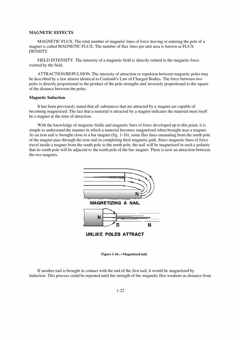
With the knowledge of magnetic fields and magnetic lines of force developed up to this point, it is
simple to understand the manner in which a material becomes magnetized when brought near a magnet.As an iron nail is brought close to a bar magnet (fig. 1-16), some flux lines emanating from the north pole
of the magnet pass through the iron nail in completing their magnetic path. Since magnetic lines of force
travel inside a magnet from the south pole to the north pole, the nail will be magnetized in such a polarity
that its south pole will be adjacent to the north pole of the bar magnet. There is now an attraction between
the two magnets.
Figure 1-16.—Magnetized nail.
If another nail is brought in contact with the end of the first nail, it would be magnetized by
induction. This process could be repeated until the strength of the magnetic flux weakens as distance from
1-22
8/6/2019 NEETS MODULE 01 - Introduction to Matter, Energy, And Direct Current
http://slidepdf.com/reader/full/neets-module-01-introduction-to-matter-energy-and-direct-current 33/278
the bar magnet increases. However, as soon as the first iron nail is pulled away from the bar magnet, all
the nails will fall. The reason being that each nail becomes a temporary magnet, and as soon as the
magnetizing force is removed, their domains once again assume a random distribution.
Magnetic induction will always produce a pole polarity on the material being magnetized opposite
that of the adjacent pole of the magnetizing force. It is sometimes possible to bring a weak north pole of a
magnet near a strong magnet north pole and note attraction between the poles. The weak magnet, whenplaced within the magnetic field of the strong magnet, has its magnetic polarity reversed by the field of
the stronger magnet. Therefore, it is attracted to the opposite pole. For this reason, you must keep a very
weak magnet, such as a compass needle, away from a strong magnet.
Magnetism can be induced in a magnetic material by several means. The magnetic material may beplaced in the magnetic field, brought into contact with a magnet, or stroked by a magnet. Stroking and
contact both indicate actual contact with the material but are considered in magnetic studies as
magnetizing by INDUCTION.
Magnetic Shielding
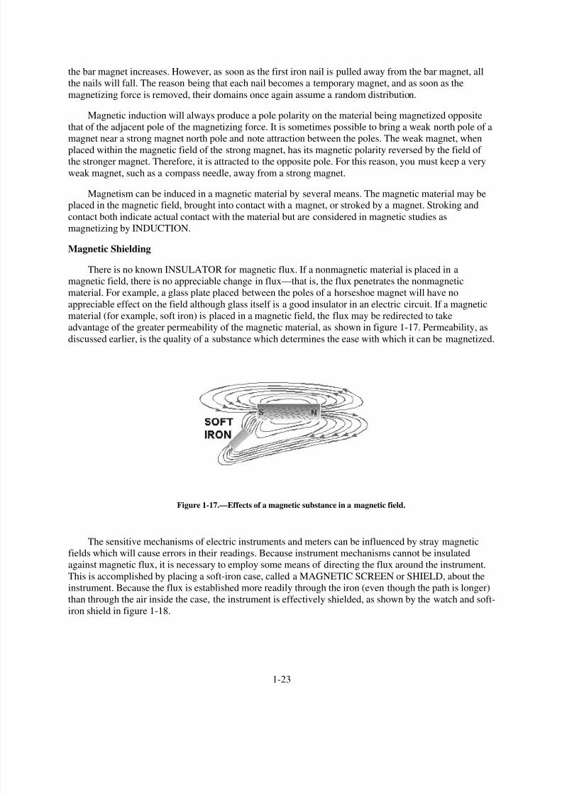
There is no known INSULATOR for magnetic flux. If a nonmagnetic material is placed in a
magnetic field, there is no appreciable change in flux—that is, the flux penetrates the nonmagneticmaterial. For example, a glass plate placed between the poles of a horseshoe magnet will have no
appreciable effect on the field although glass itself is a good insulator in an electric circuit. If a magnetic
material (for example, soft iron) is placed in a magnetic field, the flux may be redirected to take
advantage of the greater permeability of the magnetic material, as shown in figure 1-17. Permeability, as
discussed earlier, is the quality of a substance which determines the ease with which it can be magnetized.
Figure 1-17.—Effects of a magnetic substance in a magnetic field.
The sensitive mechanisms of electric instruments and meters can be influenced by stray magnetic
fields which will cause errors in their readings. Because instrument mechanisms cannot be insulatedagainst magnetic flux, it is necessary to employ some means of directing the flux around the instrument.
This is accomplished by placing a soft-iron case, called a MAGNETIC SCREEN or SHIELD, about the
instrument. Because the flux is established more readily through the iron (even though the path is longer)
than through the air inside the case, the instrument is effectively shielded, as shown by the watch and soft-
iron shield in figure 1-18.
1-23

8/6/2019 NEETS MODULE 01 - Introduction to Matter, Energy, And Direct Current
http://slidepdf.com/reader/full/neets-module-01-introduction-to-matter-energy-and-direct-current 34/278
Figure 1-18.—Magnetic shield.
MAGNETIC SHAPES
Because of the many uses of magnets, they are found in various shapes and sizes. However, magnetsusually come under one of three general classifications: bar magnets, horseshoe magnets, or ring magnets.
The bar magnet is most often used in schools and laboratories for studying the properties and effects
of magnetism. In the preceding material, the bar magnet proved very helpful in demonstrating magnetic
effects.
Another type of magnet is the ring magnet, which is used for computer memory cores. A common
application for a temporary ring magnet would be the shielding of electrical instruments.
The shape of the magnet most frequently used in electrical and electronic equipment is called thehorseshoe magnet. A horseshoe magnet is similar to a bar magnet but is bent in the shape of a horseshoe.
The horseshoe magnet provides much more magnetic strength than a bar magnet of the same size and
material because of the closeness of the magnetic poles. The magnetic strength from one pole to the otheris greatly increased due to the concentration of the magnetic field in a smaller area. Electrical measuring
devices quite frequently use horseshoe-type magnets.
CARE OF MAGNETS
A piece of steel that has been magnetized can lose much of its magnetism by improper handling. If it
is jarred or heated, there will be a disalignment of its domains resulting in the loss of some of its effective
magnetism. Had this piece of steel formed the horseshoe magnet of a meter, the meter would no longer be
1-24

8/6/2019 NEETS MODULE 01 - Introduction to Matter, Energy, And Direct Current
http://slidepdf.com/reader/full/neets-module-01-introduction-to-matter-energy-and-direct-current 35/278
operable or would give inaccurate readings. Therefore, care must be exercised when handling instruments
containing magnets. Severe jarring or subjecting the instrument to high temperatures will damage the
device.
A magnet may also become weakened from loss of flux. Thus when storing magnets, one should
always try to avoid excess leakage of magnetic flux. A horseshoe magnet should always be stored with a
keeper, a soft iron bar used to join the magnetic poles. By using the keeper while the magnet is beingstored, the magnetic flux will continuously circulate through the magnet and not leak off into space.
When bar magnets are stored, the same principle must be remembered. Therefore, bar magnets
should always be stored in pairs with a north pole and a south pole placed together. This provides a
complete path for the magnetic flux without any flux leakage.
Q31. How should a delicate instrument be protected from a magnetic field?
Q32. How should bar magnets be stored?
ELECTRICAL ENERGY
In the field of physical science, work must be defined as the PRODUCT OF FORCE ANDDISPLACEMENT. That is, the force applied to move an object and the distance the object is moved are
the factors of work performed.
It is important to notice that no work is accomplished unless the force applied causes a change in the
position of a stationary object, or a change in the velocity of a moving object. A worker may tire by
pushing against a heavy wooden crate, but unless the crate moves, no work will be accomplished.
ENERGY
In our study of energy and work, we must define energy as THE ABILITY TO DO WORK. In order
to perform any kind of work, energy must be expended (converted from one form to another). Energy
supplies the required force, or power, whenever any work is accomplished.
One form of energy is that which is contained by an object in motion. When a hammer is set inmotion in the direction of a nail, it possesses energy of motion. As the hammer strikes the nail, the energy
of motion is converted into work as the nail is driven into the wood. The distance the nail is driven into
the wood depends on the velocity of the hammer at the time it strikes the nail. Energy contained by an
object due to its motion is called KINETIC ENERGY. Assume that the hammer is suspended by a string
in a position one meter above a nail. As a result of gravitational attraction, the hammer will experience a
force pulling it downward. If the string is suddenly cut, the force of gravity will pull the hammer
downward against the nail, driving it into the wood. While the hammer is suspended above the nail it has
ability to do work because of its elevated position in the earth,s gravitational field. Since energy is the
ability to do work, the hammer contains energy.
Energy contained by an object due to its position is called POTENTIAL ENERGY. The amount of
potential energy available is equal to the product of the force required to elevate the hammer and the
height to which it is elevated.
Another example of potential energy is that contained in a tightly coiled spring. The amount of
energy released when the spring unwinds depends on the amount of force required to wind the spring
initially.
1-25

8/6/2019 NEETS MODULE 01 - Introduction to Matter, Energy, And Direct Current
http://slidepdf.com/reader/full/neets-module-01-introduction-to-matter-energy-and-direct-current 36/278
Q33. What is the definition of energy?
Q34. What type of energy does a rolling stone have?
Q35. What kind of energy does the stone have if it is at rest at the top of a hill?
Electrical Charges
From the previous study of electrostatics, you learned that a field of force exists in the space
surrounding any electrical charge. The strength of the field is directly dependent on the force of the
charge.
The charge of one electron might be used as a unit of electrical charge, since charges are created bydisplacement of electrons; but the charge of one electron is so small that it is impractical to use. The
practical unit adopted for measuring charges is the COULOMB, named after the scientist Charles
Coulomb. One coulomb is equal to the charge of 6,280,000,000,000,000,000 (six quintillion two hundred
and eighty quadrillion) or (6.28 x 10¹⁸) electrons.
When a charge of one coulomb exists between two bodies, one unit of electrical potential energy
exists, which is called the difference of potential between the two bodies. This is referred to asELECTROMOTIVE FORCE, or VOLTAGE, and the unit of measure is the VOLT.
Electrical charges are created by the displacement of electrons, so that there exists an excess of
electrons at one point, and a deficiency at another point. Consequently, a charge must always have either
a negative or positive polarity. A body with an excess of electrons is considered to be negative, whereas a
body with a deficiency of electrons is positive.
A difference of potential can exist between two points, or bodies, only if they have different charges.
In other words, there is no difference in potential between two bodies if both have a deficiency of
electrons to the same degree. If, however, one body is deficient of 6 coulombs (representing 6 volts), and
the other is deficient by 12 coulombs (representing 12 volts), there is a difference of potential of 6 volts.
The body with the greater deficiency is positive with respect to the other.
In most electrical circuits only the difference of potential between two points is of importance and
the absolute potentials of the points are of little concern. Very often it is convenient to use one standard
reference for all of the various potentials throughout a piece of equipment. For this reason, the potentials
at various points in a circuit are generally measured with respect to the metal chassis on which all parts of
the circuit are mounted. The chassis is considered to be at zero potential and all other potentials are either
positive or negative with respect to the chassis. When used as the reference point, the chassis is said to be
at GROUND POTENTIAL.
Occasionally, rather large values of voltage may be encountered, in which case the volt becomes too
small a unit for convenience. In a situation of this nature, the kilovolt (kV), meaning 1,000 volts, is
frequently used. As an example, 20,000 volts would be written as 20 kV. In other cases, the volt may be
too large a unit, as when dealing with very small voltages. For this purpose the millivolt (mV), meaningone-thousandth of a volt, and the microvolt (µV), meaning one-millionth of a volt, are used. For example,
0.001 volt would be written as 1 mV, and 0.000025 volt would be written as 25 µV. See Appendix II for
exponential symbology.
When a difference in potential exists between two charged bodies that are connected by a conductor,
electrons will flow along the conductor. This flow is from the negatively charged body to the positively
charged body, until the two charges are equalized and the potential difference no longer exists.
1-26

8/6/2019 NEETS MODULE 01 - Introduction to Matter, Energy, And Direct Current
http://slidepdf.com/reader/full/neets-module-01-introduction-to-matter-energy-and-direct-current 37/278
An analogy of this action is shown in the two water tanks connected by a pipe and valve in figure1-19. At first the valve is closed and all the water is in tank A. Thus, the water pressure across the valve is
at maximum. When the valve is opened, the water flows through the pipe from A to B until the water
level becomes the same in both tanks. The water then stops flowing in the pipe, because there is no longer
a difference in water pressure between the two tanks.
Figure 1-19.—Water analogy of electric differences of potential.
Electron movement through an electric circuit is directly proportional to the difference in potential or
electromotive force (emf), across the circuit, just as the flow of water through the pipe in figure 1-19 is
directly proportional to the difference in water level in the two tanks.
A fundamental law of electricity is that the ELECTRON FLOW IS DIRECTLY PROPORTIONAL
TO THE APPLIED VOLTAGE. If the voltage is increased, the flow is increased. If the voltage is
decreased, the flow is decreased.
Q36. What term describes voltage or emf?
Q37. Convert 2.1 kV to volts.
Q38. Express the following in more simple terms. (a) 250,000 volts, (b) 25,000,000 microvolts, (c)
0.001 millivolt.
HOW VOLTAGE IS PRODUCED
It has been demonstrated that a charge can be produced by rubbing a rubber rod with fur. Because of
the friction involved, the rod acquires electrons from the fur, making it negative; the fur becomes positive
due to the loss of electrons. These quantities of charge constitute a difference of potential between the rod
and the fur. The electrons which make up this difference of potential are capable of doing work if a
discharge is allowed to occur.
To be a practical source of voltage, the potential difference must not be allowed to dissipate, butmust be maintained continuously. As one electron leaves the concentration of negative charge, another
must be immediately provided to take its place or the charge will eventually diminish to the point where
no further work can be accomplished. A VOLTAGE SOURCE, therefore, is a device which is capable of
supplying and maintaining voltage while some type of electrical apparatus is connected to its terminals.
The internal action of the source is such that electrons are continuously removed from one terminal,
keeping it positive, and simultaneously supplied to the second terminal which maintains a negative
charge.
1-27

8/6/2019 NEETS MODULE 01 - Introduction to Matter, Energy, And Direct Current
http://slidepdf.com/reader/full/neets-module-01-introduction-to-matter-energy-and-direct-current 38/278
Presently, there are six known methods for producing a voltage or electromotive force (emf). Someof these methods are more widely used than others, and some are used mostly for specific applications.
Following is a list of the six known methods of producing a voltage.
1.
2.
3.
4.
5.
6.
FRICTION—Voltage produced by rubbing certain materials together.
PRESSURE (piezoelectricity)—Voltage produced by squeezing crystals of certain substances.
HEAT (thermoelectricity)—Voltage produced by heating the joint (junction) where two unlike
metals are joined.
LIGHT (photoelectricity)—Voltage produced by light striking photosensitive (light sensitive)
substances.
CHEMICAL ACTION—Voltage produced by chemical reaction in a battery cell.
MAGNETISM—Voltage produced in a conductor when the conductor moves through a
magnetic field, or a magnetic field moves through the conductor in such a manner as to cut the
magnetic lines of force of the field.
Voltage Produced by Friction
The first method discovered for creating a voltage was that of generation by friction. The
development of charges by rubbing a rod with fur is a prime example of the way in which a voltage is
generated by friction. Because of the nature of the materials with which this voltage is generated, it
cannot be conveniently used or maintained. For this reason, very little practical use has been found for
voltages generated by this method.
In the search for methods to produce a voltage of a larger amplitude and of a more practical nature,
machines were developed in which charges were transferred from one terminal to another by means of
rotating glass discs or moving belts. The most notable of these machines is the Van de Graaff generator. It
is used today to produce potentials in the order of millions of volts for nuclear research. As these
machines have little value outside the field of research, their theory of operation will not be describedhere.
Q39. A device which supplies a voltage is commonly referred to by what name?
Voltage Produced by Pressure
One specialized method of generating an emf utilizes the characteristics of certain ionic crystals suchas quartz, Rochelle salts, and tourmaline. These crystals have the remarkable ability to generate a voltage
whenever stresses are applied to their surfaces. Thus, if a crystal of quartz is squeezed, charges of
opposite polarity will appear on two opposite surfaces of the crystal. If the force is reversed and the
crystal is stretched, charges will again appear, but will be of the opposite polarity from those produced by
squeezing. If a crystal of this type is given a vibratory motion, it will produce a voltage of reversing
polarity between two of its sides. Quartz or similar crystals can thus be used to convert mechanical energy
into electrical energy. This phenomenon, called the PIEZOELECTRIC EFFECT, is shown in figure 1-20.
Some of the common devices that make use of piezoelectric crystals are microphones, phonograph
cartridges, and oscillators used in radio transmitters, radio receivers, and sonar equipment. This method of
generating an emf is not suitable for applications having large voltage or power requirements, but is
widely used in sound and communications systems where small signal voltages can be effectively used.
1-28
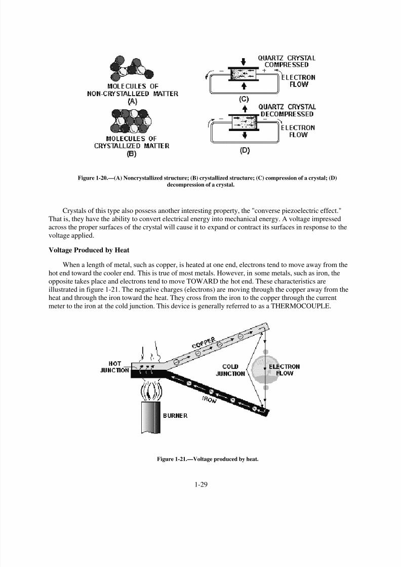
8/6/2019 NEETS MODULE 01 - Introduction to Matter, Energy, And Direct Current
http://slidepdf.com/reader/full/neets-module-01-introduction-to-matter-energy-and-direct-current 39/278

8/6/2019 NEETS MODULE 01 - Introduction to Matter, Energy, And Direct Current
http://slidepdf.com/reader/full/neets-module-01-introduction-to-matter-energy-and-direct-current 40/278
Thermocouples have somewhat greater power capacities than crystals, but their capacity is still very
small if compared to some other sources. The thermoelectric voltage in a thermocouple depends mainly
on the difference in temperature between the hot and cold junctions. Consequently, they are widely used
to measure temperature, and as heat-sensing devices in automatic temperature control equipment.
Thermocouples generally can be subjected to much greater temperatures than ordinary thermometers,such as the mercury or alcohol types.
Voltage Produced by Light
When light strikes the surface of a substance, it may dislodge electrons from their orbits around the
surface atoms of the substance. This occurs because light has energy, the same as any moving force.
Some substances, mostly metallic ones, are far more sensitive to light than others. That is, more
electrons will be dislodged and emitted from the surface of a highly sensitive metal, with a given amount
of light, than will be emitted from a less sensitive substance. Upon losing electrons, the photosensitive
(light-sensitive) metal becomes positively charged, and an electric force is created. Voltage produced in
this manner is referred to as a PHOTOELECTRIC VOLTAGE.
The photosensitive materials most commonly used to produce a photoelectric voltage are various
compounds of silver oxide or copper oxide. A complete device which operates on the photoelectric
principle is referred to as a "photoelectric cell." There are many different sizes and types of photoelectric
cells in use, and each serves the special purpose for which it is designed. Nearly all, however, have some
of the basic features of the photoelectric cells shown in figure 1-22.
1-30

8/6/2019 NEETS MODULE 01 - Introduction to Matter, Energy, And Direct Current
http://slidepdf.com/reader/full/neets-module-01-introduction-to-matter-energy-and-direct-current 41/278
Figure 1-22.—Voltage produced by light.
The cell (fig. 1-22 view A) has a curved light-sensitive surface focused on the central anode. When
light from the direction shown strikes the sensitive surface, it emits electrons toward the anode. The moreintense the light, the greater the number of electrons emitted. When a wire is connected between the
filament and the back, or dark side of the cell, the accumulated electrons will flow to the dark side. These
electrons will eventually pass through the metal of the reflector and replace the electrons leaving the
light-sensitive surface. Thus, light energy is converted to a flow of electrons, and a usable current is
developed.
The cell (fig. 1-22 view B) is constructed in layers. A base plate of pure copper is coated with light-
sensitive copper oxide. An extremely thin semitransparent layer of metal is placed over the copper oxide.
This additional layer serves two purposes:
1.
2.
It permits the penetration of light to the copper oxide.
It collects the electrons emitted by the copper oxide.
An externally connected wire completes the electron path, the same as in the reflector-type cell. The
photocell,s voltage is used as needed by connecting the external wires to some other device, which
amplifies (enlarges) it to a usable level.
The power capacity of a photocell is very small. However, it reacts to light-intensity variations in an
extremely short time. This characteristic makes the photocell very useful in detecting or accurately
1-31

8/6/2019 NEETS MODULE 01 - Introduction to Matter, Energy, And Direct Current
http://slidepdf.com/reader/full/neets-module-01-introduction-to-matter-energy-and-direct-current 42/278
controlling a great number of operations. For instance, the photoelectric cell, or some form of the
photoelectric principle, is used in television cameras, automatic manufacturing process controls, door
openers, burglar alarms, and so forth.
Voltage Produced by Chemical Action
Voltage may be produced chemically when certain substances are exposed to chemical action.
If two dissimilar substances (usually metals or metallic materials) are immersed in a solution that
produces a greater chemical action on one substance than on the other, a difference of potential will exist
between the two. If a conductor is then connected between them, electrons will flow through the
conductor to equalize the charge. This arrangement is called a primary cell. The two metallic pieces are
called electrodes and the solution is called the electrolyte. The voltaic cell illustrated in figure 1-23 is a
simple example of a primary cell. The difference of potential results from the fact that material from one
or both of the electrodes goes into solution in the electrolyte, and in the process, ions form in the vicinity
of the electrodes. Due to the electric field associated with the charged ions, the electrodes acquire charges.
Figure 1-23.—Voltaic cell.
The amount of difference in potential between the electrodes depends principally on the metals used.
The type of electrolyte and the size of the cell have little or no effect on the potential difference produced.
There are two types of primary cells, the wet cell and the dry cell. In a wet cell the electrolyte is a
liquid. A cell with a liquid electrolyte must remain in an upright position and is not readily transportable.
The dry cell, much more commonly used than the wet cell, is not actually dry, but contains an electrolyte
mixed with other materials to form a paste. Flashlights and portable radios are commonly powered by dry
cells.
Batteries are formed when several cells are connected together to increase electrical output.
1-32

8/6/2019 NEETS MODULE 01 - Introduction to Matter, Energy, And Direct Current
http://slidepdf.com/reader/full/neets-module-01-introduction-to-matter-energy-and-direct-current 43/278
Voltage Produced by Magnetism
Magnets or magnetic devices are used for thousands of different jobs. One of the most useful and
widely employed applications of magnets is in the production of vast quantities of electric power from
mechanical sources. The mechanical power may be provided by a number of different sources, such as
gasoline or diesel engines, and water or steam turbines. However, the final conversion of these source
energies to electricity is done by generators employing the principle of electromagnetic induction. These
generators, of many types and sizes, are discussed in other modules in this series. The important subject to
be discussed here is the fundamental operating principle of ALL such electromagnetic-induction
generators.
To begin with, there are three fundamental conditions which must exist before a voltage can be
produced by magnetism.
1.
2.
3.
There must be a CONDUCTOR in which the voltage will be produced.
There must be a MAGNETIC FIELD in the conductor,s vicinity.
There must be relative motion between the field and conductor. The conductor must be moved so
as to cut across the magnetic lines of force, or the field must be moved so that the lines of force
are cut by the conductor.
In accordance with these conditions, when a conductor or conductors MOVE ACROSS a magnetic
field so as to cut the lines of force, electrons WITHIN THE CONDUCTOR are propelled in one direction
or another. Thus, an electric force, or voltage, is created.
In figure 1-24, note the presence of the three conditions needed for creating an induced voltage.
Figure 1-24.—Voltage produced by magnetism.
1.
2.
3.
A magnetic field exists between the poles of the C-shaped magnet.
There is a conductor (copper wire).
There is a relative motion. The wire is moved back and forth ACROSS the magnetic field.
1-33

8/6/2019 NEETS MODULE 01 - Introduction to Matter, Energy, And Direct Current
http://slidepdf.com/reader/full/neets-module-01-introduction-to-matter-energy-and-direct-current 44/278
In figure 1-24 view A, the conductor is moving TOWARD the front of the page and the electronsmove from left to right. The movement of the electrons occurs because of the magnetically induced emf
acting on the electrons in the copper. The right-hand end becomes negative, and the left-hand end
positive. The conductor is stopped at view B, motion is eliminated (one of the three required conditions),
and there is no longer an induced emf. Consequently, there is no longer any difference in potential
between the two ends of the wire. The conductor at view C is moving away from the front of the page. An
induced emf is again created. However, note carefully that the REVERSAL OF MOTION has caused aREVERSAL OF DIRECTION in the induced emf.
If a path for electron flow is provided between the ends of the conductor, electrons will leave the
negative end and flow to the positive end. This condition is shown in part view D. Electron flow will
continue as long as the emf exists. In studying figure 1-24, it should be noted that the induced emf could
also have been created by holding the conductor stationary and moving the magnetic field back and forth.
The more complex aspects of power generation by use of mechanical motion and magnetism are
discussed later in this series, under the heading "Generators and Motors."
Q40. Name the six methods of producing a voltage.
Q41. The piezoelectric effect is an example of a voltage being produced by what method?
Q42. A thermocouple is a device that produces voltage by what method?
Q43. A battery uses what method to produce a voltage?
Q44. A generator uses what method to produce a voltage?
ELECTRIC CURRENT
It has been proven that electrons (negative charges) move through a conductor in response to an
electric field. ELECTRON CURRENT FLOW will be used throughout this explanation. Electron current
is defined as the directed flow of electrons. The direction of electron movement is from a region of
negative potential to a region of positive potential. Therefore electric current can be said to flow fromnegative to positive. The direction of current flow in a material is determined by the polarity of the
applied voltage. NOTE: In some electrical/electronic communities, the direction of current flow is
recognized as being from positive to negative.
Q45. According to electron theory, an electric current flows from what potential to what potential?
Random Drift
All materials are composed of atoms, each of which is capable of being ionized. If some form of
energy, such as heat, is applied to a material, some electrons acquire sufficient energy to move to a higher
energy level. As a result, some electrons are freed from their parent atom,s which then becomes ions.
Other forms of energy, particularly light or an electric field, will cause ionization to occur.
The number of free electrons resulting from ionization is dependent upon the quantity of energy
applied to a material, as well as the atomic structure of the material. At room temperature some materials,
classified as conductors, have an abundance of free electrons. Under a similar condition, materials
classified as insulators have relatively few free electrons.
In a study of electric current, conductors are of major concern. Conductors are made up of atoms that
contain loosely bound electrons in their outer orbits. Due to the effects of increased energy, these
outermost electrons frequently break away from their atoms and freely drift throughout the material. The
1-34

8/6/2019 NEETS MODULE 01 - Introduction to Matter, Energy, And Direct Current
http://slidepdf.com/reader/full/neets-module-01-introduction-to-matter-energy-and-direct-current 45/278
1-35
free electrons, also called mobile electrons, take a path that is not predictable and drift about the material
in a haphazard manner. Consequently such a movement is termed RANDOM DRIFT.
It is important to emphasize that the random drift of electrons occurs in all materials. The degree of
random drift is greater in a conductor than in an insulator.
Directed Drift
Associated with every charged body there is an electrostatic field. Bodies that are charged alike repel
one another and bodies with unlike charges attract each other. An electron will be affected by an
electrostatic field in exactly the same manner as any negatively charged body. It is repelled by a negative
charge and attracted by a positive charge. If a conductor has a difference in potential impressed across it,
as shown in figure 1-25, a direction is imparted to the random drift. This causes the mobile electrons to be
repelled away from the negative terminal and attracted toward the positive terminal. This constitutes a
general migration of electrons from one end of the conductor to the other. The directed migration of
mobile electrons due to the potential difference is called DIRECTED DRIFT.
Figure 1-25.—Directed drift.
The directed movement of the electrons occurs at a relatively low VELOCITY (rate of motion in a
particular direction). The effect of this directed movement, however, is felt almost instantaneously, as
explained by the use of figure 1-26. As a difference in potential is impressed across the conductor, the
positive terminal of the battery attracts electrons from point A. Point A now has a deficiency of electrons.
As a result, electrons are attracted from point B to point A. Point B has now developed an electrondeficiency, therefore, it will attract electrons. This same effect occurs throughout the conductor and
repeats itself from points D to C. At the same instant the positive battery terminal attracted electrons from
point A, the negative terminal repelled electrons toward point D. These electrons are attracted to point D
as it gives up electrons to point C. This process is continuous for as long as a difference of potential exists
across the conductor. Though an individual electron moves quite slowly through the conductor, the effect
of a directed drift occurs almost instantaneously. As an electron moves into the conductor at point D, an
electron is leaving at point A. This action takes place at approximately the speed of light (186,000 miles
per second).

8/6/2019 NEETS MODULE 01 - Introduction to Matter, Energy, And Direct Current
http://slidepdf.com/reader/full/neets-module-01-introduction-to-matter-energy-and-direct-current 46/278
Figure 1-26.—Effect of directed drift.
Q46. The effects of directed drift take place at what rate of speed?
Magnitude of Current Flow
Electric current has been defined as the directed movement of electrons. Directed drift, therefore, is
current and the terms can be used interchangeably. The expression directed drift is particularly helpful in
differentiating between the random and directed motion of electrons. However, CURRENT FLOW is the
terminology most commonly used in indicating a directed movement of electrons.
The magnitude of current flow is directly related to the amount of energy that passes through a
conductor as a result of the drift action. An increase in the number of energy carriers (the mobile
electrons) or an increase in the energy of the existing mobile electrons would provide an increase incurrent flow. When an electric potential is impressed across a conductor, there is an increase in the
velocity of the mobile electrons causing an increase in the energy of the carriers. There is also the
generation of an increased number of electrons providing added carriers of energy. The additional number
of free electrons is relatively small, hence the magnitude of current flow is primarily dependent on the
velocity of the existing mobile electrons.
The magnitude of current flow is affected by the difference of potential in the following manner.
Initially, mobile electrons are given additional energy because of the repelling and attracting electrostatic
field. If the potential difference is increased, the electric field will be stronger, the amount of energy
imparted to a mobile electron will be greater, and the current will be increased. If the potential difference
is decreased, the strength of the field is reduced, the energy supplied to the electron is diminished, and the
current is decreased.
Q47. What is the relationship of current to voltage in a circuit?
Measurement of Current
The magnitude of current is measured in AMPERES. A current of one ampere is said to flow when
one coulomb of charge passes a point in one second. Remember, one coulomb is equal to the charge of
6.28 x 10¹⁸ electrons.
1-36

8/6/2019 NEETS MODULE 01 - Introduction to Matter, Energy, And Direct Current
http://slidepdf.com/reader/full/neets-module-01-introduction-to-matter-energy-and-direct-current 47/278
Frequently, the ampere is much too large a unit for measuring current. Therefore, theMILLIAMPERE (mA), one-thousandth of an ampere, or the MICROAMPERE (µA), one-millionth of an
ampere, is used. The device used to measure current is called an AMMETER and will be discussed in
detail in a later module.
Q48. Convert 350 mA to amperes.
ELECTRICAL RESISTANCE
It is known that the directed movement of electrons constitutes a current flow. It is also known that
the electrons do not move freely through a conductor,s crystalline structure. Some materials offer little
opposition to current flow, while others greatly oppose current flow. This opposition to current flow is
known as RESISTANCE (R), and the unit of measure is the OHM. The standard of measure for one ohm
is the resistance provided at zero degrees Celsius by a column of mercury having a cross-sectional area of
one square millimeter and a length of 106.3 centimeters. A conductor has one ohm of resistance when an
applied potential of one volt produces a current of one ampere. The symbol used to represent the ohm is
the Greek letter omega (Ω).
Resistance, although an electrical property, is determined by the physical structure of a material. The
resistance of a material is governed by many of the same factors that control current flow. Therefore, in asubsequent discussion, the factors that affect current flow will be used to assist in the explanation of the
factors affecting resistance.
Q49. What is the symbol for ohm?
Factors That Affect Resistance
The magnitude of resistance is determined in part by the "number of free electrons" available within
the material. Since a decrease in the number of free electrons will decrease the current flow, it can be said
that the opposition to current flow (resistance) is greater in a material with fewer free electrons. Thus, the
resistance of a material is determined by the number of free electrons available in a material.
A knowledge of the conditions that limit current flow and, therefore, affect resistance can now beused to consider how the type of material, physical dimensions, and temperature will affect the resistance
of a conductor.
TYPE OF MATERIAL.—Depending upon their atomic structure, different materials will havedifferent quantities of free electrons. Therefore, the various conductors used in electrical applications
have different values of resistance.
Consider a simple metallic substance. Most metals are crystalline in structure and consist of atoms
that are tightly bound in the lattice network. The atoms of such elements are so close together that the
electrons in the outer shell of the atom are associated with one atom as much as with its neighbor. (See
fig. 1-27 view A). As a result, the force of attachment of an outer electron with an individual atom is
practically zero. Depending on the metal, at least one electron, sometimes two, and in a few cases, threeelectrons per atom exist in this state. In such a case, a relatively small amount of additional electron
energy would free the outer electrons from the attraction of the nucleus. At normal room temperature
materials of this type have many free electrons and are good conductors. Good conductors will have a low
resistance.
1-37

8/6/2019 NEETS MODULE 01 - Introduction to Matter, Energy, And Direct Current
http://slidepdf.com/reader/full/neets-module-01-introduction-to-matter-energy-and-direct-current 48/278
Figure 1-27.—Atomic spacing in conductors.
If the atoms of a material are farther apart, as illustrated in figure 1-27 view B, the electrons in the
outer shells will not be equally attached to several atoms as they orbit the nucleus. They will be attracted
by the nucleus of the parent atom only. Therefore, a greater amount of energy is required to free any of
these electrons. Materials of this type are poor conductors and therefore have a high resistance.
Silver, gold, and aluminum are good conductors. Therefore, materials composed of their atoms
would have a low resistance.
The element copper is the conductor most widely used throughout electrical applications. Silver has
a lower resistance than copper but its cost limits usage to circuits where a high conductivity is demanded.
Aluminum, which is considerably lighter than copper, is used as a conductor when weight is a major
factor.
Q50. When would silver be used as a conductor in preference to copper?
EFFECT OF CROSS-SECTIONAL AREA.—Cross-sectional area greatly affects the magnitude
of resistance. If the cross-sectional area of a conductor is increased, a greater quantity of electrons are
available for movement through the conductor. Therefore, a larger current will flow for a given amount of
applied voltage. An increase in current indicates that when the cross-sectional area of a conductor is
increased, the resistance must have decreased. If the cross-sectional area of a conductor is decreased, the
number of available electrons decreases and, for a given applied voltage, the current through the
conductor decreases. A decrease in current flow indicates that when the cross-sectional area of aconductor is decreased, the resistance must have increased. Thus, the RESISTANCE OF A
CONDUCTOR IS INVERSELY PROPORTIONAL TO ITS CROSS-SECTIONAL AREA.
The diameter of conductors used in electronics is often only a fraction of an inch, therefore, the
diameter is expressed in mils (thousandths of an inch). It is also standard practice to assign the unit
circular mil to the cross-sectional area of the conductor. The circular mil is found by squaring the
diameter when the diameter is expressed in mils. Thus, if the diameter is 35 mils (0.035 inch), the circular
1-38

8/6/2019 NEETS MODULE 01 - Introduction to Matter, Energy, And Direct Current
http://slidepdf.com/reader/full/neets-module-01-introduction-to-matter-energy-and-direct-current 49/278
mil area is equal to (35)2 or 1225 circular mils. A comparison between a square mil and a circular mil is
illustrated in figure 1-28.
Figure 1-28.—Square and circular mils.
EFFECT OF CONDUCTOR LENGTH.—The length of a conductor is also a factor which
determines the resistance of a conductor. If the length of a conductor is increased, the amount of energy
given up increases. As free electrons move from atom to atom some energy is given off as heat. The
longer a conductor is, the more energy is lost to heat. The additional energy loss subtracts from the energybeing transferred through the conductor, resulting in a decrease in current flow for a given applied
voltage. A decrease in current flow indicates an increase in resistance, since voltage was held constant.Therefore, if the length of a conductor is increased, the resistance increases. THE RESISTANCE OF A
CONDUCTOR IS DIRECTLY PROPORTIONAL TO ITS LENGTH.
Q51. Which wire has the least resistance? Wire A-copper, 1000 circular mils, 6 inches long. Wire
B-copper, 2000 circular mils, 11 inches long.
EFFECT OF TEMPERATURE.—Temperature changes affect the resistance of materials in
different ways. In some materials an increase in temperature causes an increase in resistance, whereas in
others, an increase in temperature causes a decrease in resistance. The amount of change of resistance per
unit change in temperature is known as the TEMPERATURE COEFFICIENT. If for an increase in
temperature the resistance of a material increases, it is said to have a POSITIVE TEMPERATURE
COEFFICIENT. A material whose resistance decreases with an increase in temperature has a
NEGATIVE TEMPERATURE COEFFICIENT. Most conductors used in electronic applications have a
positive temperature coefficient. However, carbon, a frequently used material, is a substance having a
negative temperature coefficient. Several materials, such as the alloys constantan and manganin, are
considered to have a ZERO TEMPERATURE COEFFICIENT because their resistance remains relatively
constant for changes in temperature.
Q52. Which temperature coefficient indicates a material whose resistance increases as temperature
increases?
1-39

8/6/2019 NEETS MODULE 01 - Introduction to Matter, Energy, And Direct Current
http://slidepdf.com/reader/full/neets-module-01-introduction-to-matter-energy-and-direct-current 50/278
Q53. What term describes a material whose resistance remains relatively constant with changes in
temperature?
CONDUCTANCE
Electricity is a study that is frequently explained in terms of opposites. The term that is the opposite
of resistance is CONDUCTANCE. Conductance is the ability of a material to pass electrons. The factorsthat affect the magnitude of resistance are exactly the same for conductance, but they affect conductance
in the opposite manner. Therefore, conductance is directly proportional to area, and inversely proportional
to the length of the material. The temperature of the material is definitely a factor, but assuming a
constant temperature, the conductance of a material can be calculated.
The unit of conductance is the MHO (G), which is ohm spelled backwards. Recently the term mho
has been redesignated SIEMENS (S). Whereas the symbol used to represent resistance (R) is the Greek
letter omega (Ω), the symbol used to represent conductance (G) is (S). The relationship that exists
between resistance (R) and conductance (G) or (S) is a reciprocal one. A reciprocal of a number is one
divided by that number. In terms of resistance and conductance:
Q54. What is the unit of conductance and what other term is sometimes used?
Q55. What is the relationship between conductance and resistance?
ELECTRICAL RESISTORS
Resistance is a property of every electrical component. At times, its effects will be undesirable.
However, resistance is used in many varied ways. RESISTORS are components manufactured to possess
specific values of resistance. They are manufactured in many types and sizes. When drawn using its
schematic representation, a resistor is shown as a series of jagged lines, as illustrated in figure 1-29.
1-40

8/6/2019 NEETS MODULE 01 - Introduction to Matter, Energy, And Direct Current
http://slidepdf.com/reader/full/neets-module-01-introduction-to-matter-energy-and-direct-current 51/278
Figure 1-29.—Types of resistors.
Q56. What is schematic symbol for a resistor?
Composition of Resistors
One of the most common types of resistors is the molded composition, usually referred to as the
carbon resistor. These resistors are manufactured in a variety of sizes and shapes. The chemical
composition of the resistor determines its ohmic value and is accurately controlled by the manufacturer in
the development process. They are made in ohmic values that range from one ohm to millions of ohms.
The physical size of the resistor is related to its wattage rating, which is the ability of resistor to dissipate
heat caused by the resistance.
Carbon resistors, as you might suspect, have as their principal ingredient the element carbon. In the
manufacturer of carbon resistors, fillers or binders are added to the carbon to obtain various resistor
values. Examples of these fillers are clay, bakelite, rubber, and talc. These fillers are doping agents and
cause the overall conduction characteristics to change.
Carbon resistors are the most common resistors found because they are easy to manufacturer,
inexpensive, and have a tolerance that is adequate for most electrical and electronic applications. Their
prime disadvantage is that they have a tendency to change value as they age. One other disadvantage of
carbon resistors is their limited power handling capacity.
The disadvantage of carbon resistors can be overcome by the use of WIREWOUND resistors (fig.
1-29 (B) and (C)). Wirewound resistors have very accurate values and possess a higher current handling
capability than carbon resistors. The material that is frequently used to manufacture wirewound resistors
1-41

8/6/2019 NEETS MODULE 01 - Introduction to Matter, Energy, And Direct Current
http://slidepdf.com/reader/full/neets-module-01-introduction-to-matter-energy-and-direct-current 52/278
is German silver which is composed of copper, nickel, and zinc. The qualities and quantities of these
elements present in the wire determine the resistivity of the wire. (The resistivity of the wire is the
measure or ability of the wire to resist current. Usually the percent of nickel in the wire determines the
resistivity.) One disadvantage of the wirewound resistor is that it takes a large amount of wire to
manufacture a resistor of high ohmic value, thereby increasing the cost. A variation of the wirewound
resistor provides an exposed surface to the resistance wire on one side. An adjustable tap is attached to
this side. Such resistors, sometimes with two or more adjustable taps, are used as voltage dividers inpower supplies and other applications where a specific voltage is desired to be "tapped" off.
Q57. What does the wattage rating of a resistor indicate?
Q58. What are the two disadvantages of carbon-type resistors?
Q59. What type resistor should be used to overcome the disadvantages of the carbon resistor?
Fixed and Variable Resistors
There are two kinds of resistors, FIXED and VARIABLE. The fixed resistor will have one value andwill never change (other than through temperature, age, etc.). The resistors shown in A and B of figure
1-29 are classed as fixed resistors. The tapped resistor illustrated in B has several fixed taps and makesmore than one resistance value available. The sliding contact resistor shown in C has an adjustable collar
that can be moved to tap off any resistance within the ohmic value range of the resistor.
There are two types of variable resistors, one called a POTENTIOMETER and the other a
RHEOSTAT (see views D and E of fig. 1-29.) An example of the potentiometer is the volume control on
your radio, and an example of the rheostat is the dimmer control for the dash lights in an automobile.
There is a slight difference between them. Rheostats usually have two connections, one fixed and the
other moveable. Any variable resistor can properly be called a rheostat. The potentiometer always has
three connections, two fixed and one moveable. Generally, the rheostat has a limited range of values and a
high current-handling capability. The potentiometer has a wide range of values, but it usually has a
limited current-handling capability. Potentiometers are always connected as voltage dividers. (Voltage
dividers are discussed in Chapter 3.)
Q60. Describe the differences between the rheostat connections and those of the potentiometer.
Q61. Which type of variable resistor should you select for controlling a large amount of current?
Wattage Rating
When a current is passed through a resistor, heat is developed within the resistor. The resistor mustbe capable of dissipating this heat into the surrounding air; otherwise, the temperature of the resistor rises
causing a change in resistance, or possibly causing the resistor to burn out.
The ability of the resistor to dissipate heat depends upon the design of the resistor itself. This ability
to dissipate heat depends on the amount of surface area which is exposed to the air. A resistor designed todissipate a large amount of heat must therefore have a large physical size. The heat dissipating capability
of a resistor is measured in WATTS (this unit will be explained later in chapter 3). Some of the more
common wattage ratings of carbon resistors are: one-eighth watt, one-fourth watt, one-half watt, one watt,
and two watts. In some of the newer state-of-the-art circuits of today, much smaller wattage resistors are
used. Generally, the type that you will be able to physically work with are of the values given. The higher
the wattage rating of the resistor the larger is the physical size. Resistors that dissipate very large amounts
of power (watts) are usually wirewound resistors. Wirewound resistors with wattage ratings up to 50
1-42

8/6/2019 NEETS MODULE 01 - Introduction to Matter, Energy, And Direct Current
http://slidepdf.com/reader/full/neets-module-01-introduction-to-matter-energy-and-direct-current 53/278
watts are not uncommon. Figure 1-30 shows some resistors which have different wattage ratings. Notice
the relative sizes of the resistors.
Figure 1-30.—Resistors of different wattage ratings.
Standard Color Code System
In the standard color code system, four bands are painted on the resistor, as shown in figure 1-31.
Figure 1-31.—Resistor color codes.
1-43

8/6/2019 NEETS MODULE 01 - Introduction to Matter, Energy, And Direct Current
http://slidepdf.com/reader/full/neets-module-01-introduction-to-matter-energy-and-direct-current 54/278
Examples of resistor color codes.
The color of the first band indicates the value of the first significant digit. The color of the secondband indicates the value of the second significant digit. The third color band represents a decimal
multiplier by which the first two digits must be multiplied to obtain the resistance value of the resistor.
The colors for the bands and their corresponding values are shown in Table 1-1.
Table 1-1.―Standard Color Code for Resistors
COLOR SIGNIFICANT
FIGURE
DECIMAL
MULTIPLIER
TOLERANCE
PERCENT
RELIABILITY
LEVEL PER 1,000
HRS.
BLACK 0 1 PERCENT —
BROWN 1 10 1 1.0%
RED 2 100 2 0.1%
ORANGE 3 1,000 — 0.01%
YELLOW 4 10,000 — 0.001%
GREEN 5 100,000 — —
BLUE 6 1,000,000 — —
VIOLET 7 10,000,000 — —
GRAY 8 100,000,000 — —
WHITE 9 1,000,000,000 — —
GOLD — .1 5 —
SILVER — .01 10 —NO COLOR — — 20 —
Use the example colors shown in figure 1-31. Since red is the color of the first band, the first
significant digit is 2. The second band is violet, therefore the second significant digit is 7. The third band
is orange, which indicates that the number formed as a result of reading the first two bands is multiplied
by 1000. In this case 27 x 1000 = 27,000 ohms. The last band on the resistor indicates the tolerance; that
is, the manufacturer,s allowable ohmic deviation above and below the numerical value indicated by the
1-44

8/6/2019 NEETS MODULE 01 - Introduction to Matter, Energy, And Direct Current
http://slidepdf.com/reader/full/neets-module-01-introduction-to-matter-energy-and-direct-current 55/278
resistor,s color code. In this example, the color silver indicates a tolerance of 10 percent. In other words,
the actual value of the resistor may fall somewhere within 10 percent above and 10 percent below the
value indicated by the color code. This resistor has an indicated value of 27,000 ohms. Its tolerance is 10
percent x 27,000 ohms, or 2,700 ohms. Therefore, the resistor,s actual value is somewhere between
24,300 ohms and 29,700 ohms.
When measuring resistors, you will find situations in which the quantities to be measured may beextremely large, and the resulting number using the basic unit, the ohm, may prove too cumbersome.
Therefore, a metric system prefix is usually attached to the basic unit of measurement to provide a more
manageable unit. Two of the most commonly used prefixes are kilo and mega. Kilo is the prefix used to
represent thousand and is abbreviated k. Mega is the prefix used to represent million and is abbreviated
M.
In the example given above, the 27,000-ohm resistor could have been written as 27 kilohms or
27 k Ω. Other examples are: 1,000 ohms = 1 k Ω; 10,000 ohms = 10 k Ω; 100,000 ohms = 100 k Ω.
Likewise, 1,000,000 ohms is written as 1 megohm or 1 MΩ and 10,000,000 ohms = 10 MΩ.
Q62. A carbon resistor has a resistance of 50 ohms, and a tolerance of 5 percent. What are the colors of
bands one, two, three, and four, respectively?
SIMPLIFYING THE COLOR CODE.—Resistors are the most common components used in
electronics. The technician must identify, select, check, remove, and replace resistors. Resistors and
resistor circuits are usually the easiest branches of electronics to understand.
The resistor color code sometimes presents problems to a technician. It really should not, because
once the resistor color code is learned, you should remember it for the rest of your life.
Black, brown, red, orange, yellow, green, blue, violet, gray, white—this is the order of colors you
should know automatically. There is a memory aid that will help you remember the code in its proper
order. Each word starts with the first letter of the colors. If you match it up with the color code, you will
not forget the code.
Bad Boys Run Over Yellow Gardenias Behind Victory Garden Walls,
or:
Black — Bad
Brown — Boys
Red — Run
Orange — Over
Yellow — Yellow
Green — Gardenias
Blue — Behind
Violet — VictoryGray — Garden
White — Walls
There are many other memory aid sentences that you might want to ask about from experienced
technicians. You might find one of the other sentences easier to remember.
There is still a good chance that you will make a mistake on a resistor,s color band. Most technicians
do at one time or another. If you make a mistake on the first two significant colors, it usually is not too
1-45

8/6/2019 NEETS MODULE 01 - Introduction to Matter, Energy, And Direct Current
http://slidepdf.com/reader/full/neets-module-01-introduction-to-matter-energy-and-direct-current 56/278
serious. If you make a miscue on the third band, you are in trouble, because the value is going to be at
least 10 times too high or too low. Some important points to remember about the third band are:
When the third band is . . . .
Black, the resistor,s value is less than 100 ohms.
Brown, the resistor,s value is in hundreds of ohms.
Red, the resistor,s value is in thousands of ohms.
Orange, the resistor,s value is in tens of thousands of ohms.
Yellow, the resistor,s value is in hundreds of thousands of ohms.
Green, the resistor,s value is in megohms.
Blue, the resistor,s value is in tens of megohms or more.
Although you may find any of the above colors in the third band, red, orange, and yellow are the
most common. In some cases, the third band will be silver or gold. You multiply the first two bands by0.01 if it is silver, and 0.1 if it is gold.
The fourth band, which is the tolerance band, usually does not present too much of a problem. If
there is no fourth band, the resistor has a 20-percent tolerance; a silver fourth band indicates a 10-percent
tolerance; and a gold fourth band indicates a 5-percent tolerance. Resistors that conform to military
specifications have a fifth band. The fifth band indicates the reliability level per 1,000 hours of operation
as follows:
Fifth band color Level
Brown 1.0%
Red 0.1%
Orange 0.01%Yellow 0.001%
For a resistor whose the fifth band is color coded brown, the resistor,s chance of failure will not
exceed 1 percent for every 1,000 hours of operation.
In equipment such as the Navy,s complex computers, the reliability level is very significant. For
example, in a piece of equipment containing 10,000 orange fifth-band resistors, no more than one resistor
will fail during 1,000 hours of operation. This is very good reliability. More information on resistors is
contained in NEETS Module 19.
Q63. A carbon resistor has the following color bands: The first band is yellow, followed by violet,
yellow, and silver. What is the ohmic value of the resistor?
Q64. The same resistor mentioned in question 63 has a yellow fifth band. What does this signify?
Q65. A resistor is handed to you for identification with the following color code: the first band is blue,
followed by gray, green, gold, and brown. What is the resistor ,s value?
1-46

8/6/2019 NEETS MODULE 01 - Introduction to Matter, Energy, And Direct Current
http://slidepdf.com/reader/full/neets-module-01-introduction-to-matter-energy-and-direct-current 57/278
Some resistors, both wirewound and composition, will not use the resistor color code. These resistors
will have the ohmic value and tolerance imprinted on the resistor itself.
SUMMARY
With the completion of this chapter, you now have gained the necessary information which is the
foundation for the further study of electricity. The following is a summary of the important parts in the
chapter.
In describing the composition of matter, the following terms are important for you to remember:
MATTER is defined as anything that occupies space and has weight.
AN ELEMENT is a substance which cannot be reduced to a simpler substance by chemical means.
A COMPOUND is a chemical combination of elements which can be separated by chemical means,
but not by physical means. It is created by chemically combining two or more elements.
A MIXTURE is a combination of elements or compounds that can be separated by physical means.
A MOLECULE is the chemical combination of two or more atoms. In a compound, the molecule is
the smallest particle that has all the characteristics of the compound.
AN ATOM is the smallest particle of an element that retains the characteristics of that element. An
atom is made up of electrons, protons, and neutrons. The number and arrangement of these subatomic
particles determine the kind of element.
AN ELECTRON is considered to be a negative charge of electricity.
A PROTON is considered to be a positive charge of electricity.
A NEUTRON is a neutral particle in that it has no electrical charge.
ENERGY in an electron is of two types—kinetic (energy of motion) and potential (energy of
position).
1-47

8/6/2019 NEETS MODULE 01 - Introduction to Matter, Energy, And Direct Current
http://slidepdf.com/reader/full/neets-module-01-introduction-to-matter-energy-and-direct-current 58/278
ENERGY LEVELS of the electron exist because the electron has mass and motion. The motiongives it kinetic energy and its position gives it potential energy. Energy balance keeps the electron in orbit
and should it gain energy it will assume an orbit further from the center of the atom. It will remain at that
level for only a fraction of a second before it radiates the excess energy and goes back to a lower orbit.
SHELLS AND SUBSHELLS of electrons are the orbits of the electrons in the atom. Each shell
contains a maximum of 2 times its number squared electrons. Shells are lettered K through Q, starting
with K, which is the closest to the nucleus. The shell can be split into 4 subshells labeled s, p, d, and f,
which can contain 2, 6, 10, and 14 electrons, respectively.
VALENCE OF AN ATOM is determined by the number of electrons in the outermost shell. The
shell is referred to as the valence shell, and the electrons within it are valence electrons. An atom with few
valence electrons requires little energy to free the valence electrons.
IONIZATION refers to the electrons contained in an atom. An atom with a positive charge has lost
some of its electrons, and is called a positive ion. A negatively charged atom is a negative ion.
1-48

8/6/2019 NEETS MODULE 01 - Introduction to Matter, Energy, And Direct Current
http://slidepdf.com/reader/full/neets-module-01-introduction-to-matter-energy-and-direct-current 59/278
CONDUCTORS, SEMICONDUCTORS, AND INSULATORS are categorized as such by thenumber of valence electrons in their atoms. The conductor normally has 3 or less valence electrons and
offers little opposition to the flow of electrons (electric current). The insulator contains 5 or more valence
electrons and offers high opposition to electron flow. The semiconductor usually has four valence
electrons of conductivity and is in the midrange. The best conductors in order of conductance are silver,
copper, gold, and aluminum.
CHARGED BODIES affect each other as follows: When two bodies having unequal charges are
brought close to each other, they will tend to attract each other in an attempt to equalize their respective
charges. When two bodies, both having either positive or negative charges, are brought close together,
they tend to repel each other as no equalization can occur. When the charge on one body is high enough
with respect to the charge on an adjacent body, an equalizing current will flow between the bodies
regardless of the conductivity of the material containing the bodies.
A NEUTRAL BODY may be attracted to either a positively or negatively charged body due to the
relative difference in their respective charges.
CHARGED BODIES will attract or repel each other with a force that is directly proportional to the
product of their individual charges and inversely proportional to the square of the distance between the
bodies.
1-49

8/6/2019 NEETS MODULE 01 - Introduction to Matter, Energy, And Direct Current
http://slidepdf.com/reader/full/neets-module-01-introduction-to-matter-energy-and-direct-current 60/278
ELECTROSTATIC LINES of force are a graphic representation of the field around a charged
body. These lines are imaginary. Lines from a positively charged body are indicated as flowing out from
the body, while lines from a negatively charged body are indicated as flowing into the body.
MAGNETISM is that property of a material which enables it to attract pieces of iron. A material
with this property is called a magnet. Any material that is attracted to a magnet can be made into a magnet
itself.
FERROMAGNETIC MATERIALS are materials that are easy to magnetize; e.g., iron, steel, and
cobalt.
NATURAL MAGNETS, called magnetite, lodestones, or leading stones, were the first magnets tobe studied. Most magnets in practical use are artificial or man-made magnets, and are made either by
electrical means or by stroking a magnetic material with a magnet.
RELUCTANCE is defined as the opposition of a material to being magnetized.
PERMEABILITY is defined as the ease with which a material accepts magnetism. A material
which is easy to magnetize does not hold its magnetism very long, and vice versa.
RETENTIVITY is defined as the ability of a material to retain magnetism.
A MAGNETIC POLE is located at each end of a magnet. The majority of the magnetic force is
concentrated at these poles and is approximately equal at both poles.
1-50

8/6/2019 NEETS MODULE 01 - Introduction to Matter, Energy, And Direct Current
http://slidepdf.com/reader/full/neets-module-01-introduction-to-matter-energy-and-direct-current 61/278
THE NORTH POLE, or north seeking pole, of a magnet freely suspended on a string always points
toward the north geographical pole.
THE LIKE POLES of magnets repel each other, while the unlike poles attract each other.
1-51

8/6/2019 NEETS MODULE 01 - Introduction to Matter, Energy, And Direct Current
http://slidepdf.com/reader/full/neets-module-01-introduction-to-matter-energy-and-direct-current 62/278
WEBER,S THEORY OF MAGNETISM assumes that all magnetic material is made up of
magnetic molecules which, if lined up in north to south pole order, will be a magnet. If not lined up, the
magnetic fields about the molecules will neutralize each other and no magnetic effect will be noted.
THE DOMAIN THEORY OF MAGNETISM states that if the electrons of the atoms in a material
spin more in one direction than in the other, the material will become magnetized.
A MAGNETIC FIELD is said to exist in the space surrounding a magnet.
1-52

8/6/2019 NEETS MODULE 01 - Introduction to Matter, Energy, And Direct Current
http://slidepdf.com/reader/full/neets-module-01-introduction-to-matter-energy-and-direct-current 63/278
MAGNETIC LINES OF FORCE are imaginary lines used to describe the patterns of the magnetic
field about a magnet. These lines are assumed to flow externally from the north pole and into the south
pole.
MAGNETIC FLUX is the total number of magnetic lines of force leaving or entering the pole of a
magnet.
1-53

8/6/2019 NEETS MODULE 01 - Introduction to Matter, Energy, And Direct Current
http://slidepdf.com/reader/full/neets-module-01-introduction-to-matter-energy-and-direct-current 64/278
FLUX DENSITY is the number of flux lines per unit area.
FIELD INTENSITY or the intensity of a magnetic field is directly related to the magnetic force
exerted by the field.
THE INTENSITY OF ATTRACTION/REPULSION between magnetic poles may be described
by a law almost identical to Coulomb,s Law of Charged Bodies, that is, the force between two poles is
directly proportional to the product of the pole strengths and inversely proportional to the square of the
distance between the poles.
MAGNETIC SHIELDING can be accomplished by placing a soft iron shield around the object to
be protected, thus directing the lines of force around the object.
1-54
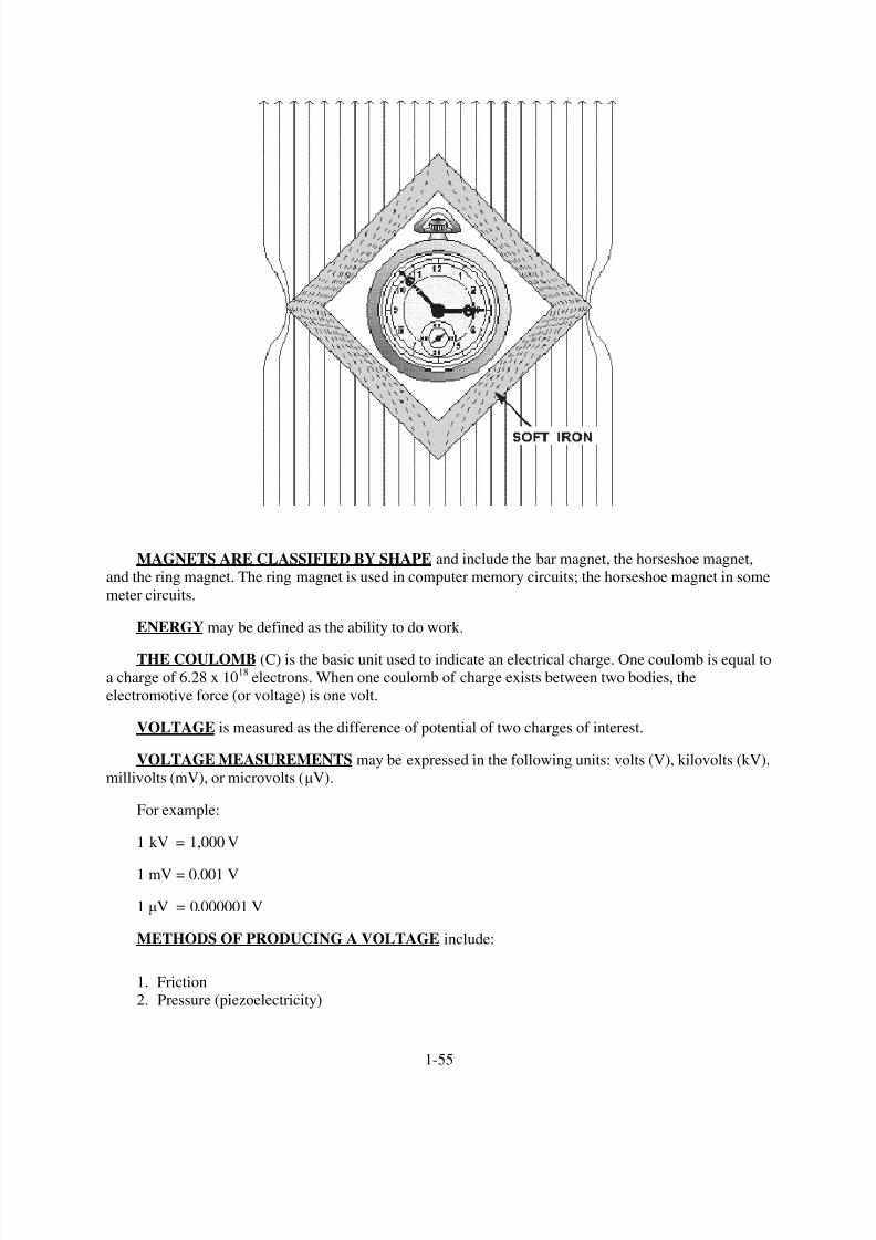
8/6/2019 NEETS MODULE 01 - Introduction to Matter, Energy, And Direct Current
http://slidepdf.com/reader/full/neets-module-01-introduction-to-matter-energy-and-direct-current 65/278
MAGNETS ARE CLASSIFIED BY SHAPE and include the bar magnet, the horseshoe magnet,
and the ring magnet. The ring magnet is used in computer memory circuits; the horseshoe magnet in some
meter circuits.
ENERGY may be defined as the ability to do work.
THE COULOMB (C) is the basic unit used to indicate an electrical charge. One coulomb is equal to
a charge of 6.28 x 10¹⁸
electrons. When one coulomb of charge exists between two bodies, the
electromotive force (or voltage) is one volt.
VOLTAGE is measured as the difference of potential of two charges of interest.
VOLTAGE MEASUREMENTS may be expressed in the following units: volts (V), kilovolts (kV),
millivolts (mV), or microvolts (µV).
For example:
1 kV = 1,000 V
1 mV = 0.001 V
1 µV = 0.000001 V
METHODS OF PRODUCING A VOLTAGE include:
1. Friction
2. Pressure (piezoelectricity)
1-55

8/6/2019 NEETS MODULE 01 - Introduction to Matter, Energy, And Direct Current
http://slidepdf.com/reader/full/neets-module-01-introduction-to-matter-energy-and-direct-current 66/278
3. Heat (thermoelectricity)
1-56

8/6/2019 NEETS MODULE 01 - Introduction to Matter, Energy, And Direct Current
http://slidepdf.com/reader/full/neets-module-01-introduction-to-matter-energy-and-direct-current 67/278
4. Light (photoelectricity)
5. Chemical action (battery)
1-57

8/6/2019 NEETS MODULE 01 - Introduction to Matter, Energy, And Direct Current
http://slidepdf.com/reader/full/neets-module-01-introduction-to-matter-energy-and-direct-current 68/278
6. Magnetism (electromagnetic induction generator)
ELECTROMAGNETIC INDUCTION GENERATOR To produce voltage by use of magnetism,three conditions must be met: There must be a CONDUCTOR in which the voltage will be produced;
there must be a MAGNETIC FIELD in the conductor,s vicinity; and there must be relative motion
between the field and conductor. When these conditions are met, electrons WITHIN THE CONDUCTOR
are propelled in one direction or another, creating an electromotive force, or voltage.
1-58
8/6/2019 NEETS MODULE 01 - Introduction to Matter, Energy, And Direct Current
http://slidepdf.com/reader/full/neets-module-01-introduction-to-matter-energy-and-direct-current 69/278
ELECTRON CURRENT is based on the assumption that electron current flow is from negative to
positive through a circuit.
AN ELECTRIC CURRENT is a directed movement of electrons in a conductor or circuit.
THE AMPERE is the basic unit used to indicate an electric current. A current of one ampere is said
to flow when one coulomb of charge (6.28 x 10
18
electrons) passes a given point in one second of time.Current measurements may be expressed in the following units: ampere (A), milliampere (mA), and
microampere (µA). Current in a circuit increases in direct proportion to the voltage (emf) applied across
the circuit.
RESISTANCE is the opposition to current. The ohm is the basic unit of resistance and is
represented by the Greek letter omega (Ω). A conductor is said to have one ohm of resistance when an
emf of one volt causes one ampere of current to flow in the conductor. Resistance may be expressed in the
following units: ohm (Ω), kilohm (k Ω), and megohms (MΩ). For example, 1,000,000Ω = 1,000 k Ω = 1
MΩ.
THE RESISTANCE OF A MATERIAL is determined by the type, the physical dimensions, and
the temperature of the material that is,
1.
2.
3.
4.
A good conductor contains an abundance of free electrons.
As the cross-sectional area of a given conductor is increased, the resistance will decrease.
As the length of a conductor is increased, the resistance will increase.
In a material having a positive temperature coefficient, the resistance will increase as the
temperature is increased.
THE CONDUCTANCE OF A MATERIAL is the reciprocal of resistance.
THE UNIT OF CONDUCTANCE is the mho and the symbol is V. G or S.
THE RESISTOR is manufactured to provide a specific value of resistance.
THE CARBON RESISTOR is made of carbon, with fillers and binders blended in to control the
ohmic value.
1-59

8/6/2019 NEETS MODULE 01 - Introduction to Matter, Energy, And Direct Current
http://slidepdf.com/reader/full/neets-module-01-introduction-to-matter-energy-and-direct-current 70/278
THE RESISTANCE OF A WIREWOUND RESISTOR is determined by the metal content of thewire and the wire
,s length. Wirewound resistors may be tapped so two or more different voltage values
may be taken off the same resistor.
1-60

8/6/2019 NEETS MODULE 01 - Introduction to Matter, Energy, And Direct Current
http://slidepdf.com/reader/full/neets-module-01-introduction-to-matter-energy-and-direct-current 71/278
THE POTENTIOMETER AND THE RHEOSTAT are variable resistors and can be adjusted toany resistance value within their ohmic range. The rheostat is usually used for relatively high current
applications and has two connections; the potentiometer has 3 connections and is a relatively high-
resistance, low-current device.
Two examples of potentiometers.
Example of a rheostat.
1-61

8/6/2019 NEETS MODULE 01 - Introduction to Matter, Energy, And Direct Current
http://slidepdf.com/reader/full/neets-module-01-introduction-to-matter-energy-and-direct-current 72/278
COLOR SIGNIFICANT
FIGURE
DECIMAL
MULTIPLIER
TOLERANCE
PERCENT
RELIABILITY LEVEL
PER 1,000 HRS.
BLACK 0 1 PERCENT —
BROWN 1 10 1 1.0%
RED 2 100 2 0.1%
ORANGE 3 1,000 — 0.01%
YELLOW 4 10,000 — 0.001%
GREEN 5 100,000 — —
BLUE 6 1,000,000 — —
VIOLET 7 10,000,000 — —
GRAY 8 100,000,000 — —
WHITE 9 1,000,000,000 — —
GOLD — .1 5 —
SILVER — .01 10 —
NO COLOR — — 20 —
Table 1-1.—Standard Color Code for Resistors
THE WATTAGE RATING OF A RESISTOR is related to the resistor,s physical size, that is, the
greater the surface area exposed to the air, the larger the rating.
THE STANDARD COLOR CODE for resistors is used to determine the following:
1.
2. Tolerance
3.
Ohmic value
Reliability level (on some resistors)
1-62

8/6/2019 NEETS MODULE 01 - Introduction to Matter, Energy, And Direct Current
http://slidepdf.com/reader/full/neets-module-01-introduction-to-matter-energy-and-direct-current 73/278
ANSWERS TO QUESTIONS Q1. THROUGH Q65.
A1. Anything that occupies space and has weight. Solids, liquids, gases.
A2. A substance which cannot be reduced to a simpler substance by chemical means.
A3. A substance consisting of two or more elements.
A4. A compound is a chemical combination of elements that cannot be separated by physical means.
A mixture is a physical combination of elements and compounds that are not chemically
combined.
A5. A chemical combination of two or more atoms.
A6. Electrons-negative, protons-positive, and neutrons-neutral.
A7. Kinetic energy.
A8. Invisible light photons (ultraviolet) bombard the phosphor atom in the light tube. The phosphor
atoms emit visible light photons.
A9. The number of electrons in the outer shell.
A10. An atom with more or less than its normal number of electrons.
A11. The number of valence electrons.
A12. Through the accumulation of excess electrons.
A13. By friction.
A14. Negative.
A15. Like charges repel, and unlike charges attract with a force directly proportional to the product oftheir charges and inversely proportional to the square of the distance between them.
A16. The space between and around charged bodies.
A17. Leaving positive, entering negative.
A18. Motors, generators, speakers, computers, televisions, tape recorders, and many others.
A19. Those materials that are attracted by magnets and have the ability to become magnetized.
A20. The relative ease with which they are magnetized.
A21. A material that exhibits low reluctance and high permeability, such as iron or soft steel.
A22. The ability of a material to retain magnetism.
A23. They are very similar; like charges repel, unlike charges attract, like poles repel—unlike poles
attract.
A24. To the magnetic north pole.
A25. South pole at the right, north pole at the left.
1-63

8/6/2019 NEETS MODULE 01 - Introduction to Matter, Energy, And Direct Current
http://slidepdf.com/reader/full/neets-module-01-introduction-to-matter-energy-and-direct-current 74/278
A26. The domain theory is based upon the electron spin principle; Weber ,s theory uses the concept of
tiny molecular magnets.
A27. To enable you to "see" the magnetic field.
A28. No specific pattern, sawdust is a nonmagnetic material.
A29. An imaginary line used to illustrate magnetic effects.
A30. Electrostatic lines of force do not form closed loops.
A31. By shielding or surrounding the instrument with a soft iron case, called a magnetic shield or
screen.
A32. In pairs, with opposite poles together to provide a complete path for magnetic flux.
A33. The ability to do work.
A34. Kinetic energy.
A35. Potential energy.
A36. Difference of potential.
A37. 2100 volts.
A38. (a) 250 kV, (b) 25 V, (c) 1 µV.
A39. A voltage source.
A40. Friction, pressure, heat, light, chemical action, and magnetism.
A41. Pressure.
A42. Heat.
A43. Chemical.
A44. Magnetic.
A45. Electron theory assumes that electron flow is from negative to positive.
A46. The speed of light (186,000 miles per second, 300,000,000 meters per second).
A47. Current increases as voltage increases.
A48. 0.35 amperes.
A49. Ω
A50. When the need for conductivity is great enough to justify the additional expense.
A51. Wire B.
A52. Positive.
1-64

8/6/2019 NEETS MODULE 01 - Introduction to Matter, Energy, And Direct Current
http://slidepdf.com/reader/full/neets-module-01-introduction-to-matter-energy-and-direct-current 75/278
A53. Zero temperature coefficient.
A54. The mho (v), siemens.
A55. They are reciprocals of each other.
A56.
A57. Its ability to dissipate heat.
A58. 1. Change value with age. 2. Limited power capacity.
A59. The wirewound resistor.
A60. The rheostat may have two connections, one fixed and one moveable; the potentiometer always
has three connections, one moveable and two fixed.
A61. The rheostat.
A62. The bands are green, black, black, and gold.
A63. 470,000 ohms (470 kilohms).
A64. The resistor ,s chance of failure is 0.001 percent for 1000 hours of operation.
A65. 6,800,000 ohms (6.8 megohms), with 5% tolerance, and a 1% reliability level.
1-65

8/6/2019 NEETS MODULE 01 - Introduction to Matter, Energy, And Direct Current
http://slidepdf.com/reader/full/neets-module-01-introduction-to-matter-energy-and-direct-current 76/278

8/6/2019 NEETS MODULE 01 - Introduction to Matter, Energy, And Direct Current
http://slidepdf.com/reader/full/neets-module-01-introduction-to-matter-energy-and-direct-current 77/278
2-1
CHAPTER 2
BATTERIES
LEARNING OBJECTIVES
Upon completing this chapter, you will be able to:
1. State the purpose of a cell.
2. State the purpose of the three parts of a cell.
3. State the difference between the two types of cells.
4. Explain the chemical process that takes place in the primary and secondary cells.
5. Recognize and define the terms electrochemical action, anode, cathode, and electrolyte.
6. State the causes of polarization and local action and describe methods of preventing these effects.
7. Identify the parts of a dry cell.
8. Identify the various dry cells in use today and some of their capabilities and limitations.
9. Identify the four basic secondary cells, their construction, capabilities, and limitations.
10. Define a battery, and identify the three ways of combining cells to form a battery.
11. Describe general maintenance procedures for batteries including the use of the hydrometer,
battery capacity, and rating and battery charging.
12. Identify the five types of battery charges.
13. Observe the safety precautions for working with and around batteries.
INTRODUCTION
The purpose of this chapter is to introduce and explain the basic theory and characteristics of
batteries. The batteries which are discussed and illustrated have been selected as representative of many
models and types which are used in the Navy today. No attempt has been made to cover every type of
battery in use, however, after completing this chapter you will have a good working knowledge of thebatteries which are in general use.
First, you will learn about the building block of all batteries, the CELL. The explanation will explore
the physical makeup of the cell and the methods used to combine cells to provide useful voltage, current,
and power. The chemistry of the cell and how chemical action is used to convert chemical energy to
electrical energy are also discussed.
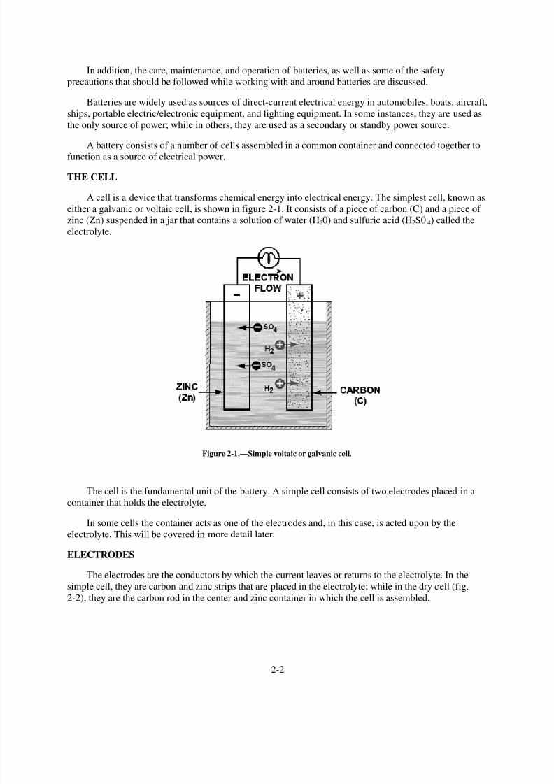
8/6/2019 NEETS MODULE 01 - Introduction to Matter, Energy, And Direct Current
http://slidepdf.com/reader/full/neets-module-01-introduction-to-matter-energy-and-direct-current 78/278
2-2
In addition, the care, maintenance, and operation of batteries, as well as some of the safety
precautions that should be followed while working with and around batteries are discussed.
Batteries are widely used as sources of direct-current electrical energy in automobiles, boats, aircraft,
ships, portable electric/electronic equipment, and lighting equipment. In some instances, they are used as
the only source of power; while in others, they are used as a secondary or standby power source.
A battery consists of a number of cells assembled in a common container and connected together to
function as a source of electrical power.
THE CELL
A cell is a device that transforms chemical energy into electrical energy. The simplest cell, known as
either a galvanic or voltaic cell, is shown in figure 2-1. It consists of a piece of carbon (C) and a piece of
zinc (Zn) suspended in a jar that contains a solution of water (H20) and sulfuric acid (H2S0 4) called the
electrolyte.
Figure 2-1.—Simple voltaic or galvanic cell.
The cell is the fundamental unit of the battery. A simple cell consists of two electrodes placed in a
container that holds the electrolyte.
In some cells the container acts as one of the electrodes and, in this case, is acted upon by the
electrolyte. This will be covered in more detail later.
ELECTRODES
The electrodes are the conductors by which the current leaves or returns to the electrolyte. In the
simple cell, they are carbon and zinc strips that are placed in the electrolyte; while in the dry cell (fig.
2-2), they are the carbon rod in the center and zinc container in which the cell is assembled.

8/6/2019 NEETS MODULE 01 - Introduction to Matter, Energy, And Direct Current
http://slidepdf.com/reader/full/neets-module-01-introduction-to-matter-energy-and-direct-current 79/278
2-3
Figure 2-2.—Dry cell, cross-sectional view.
ELECTROLYTE
The electrolyte is the solution that acts upon the electrodes. The electrolyte, which provides a path
for electron flow, may be a salt, an acid, or an alkaline solution. In the simple galvanic cell, the electrolyte
is in a liquid form. In the dry cell, the electrolyte is a paste.
CONTAINER
The container which may be constructed of one of many different materials provides a means of
holding (containing) the electrolyte. The container is also used to mount the electrodes. In the voltaic cell
the container must be constructed of a material that will not be acted upon by the electrolyte.
Q1. What is the purpose of a cell?
Q2. What are the three parts of a cell?
Q3. What is the purpose of each of the three parts of a cell?
PRIMARY CELL
A primary cell is one in which the chemical action eats away one of the electrodes, usually the
negative electrode. When this happens, the electrode must be replaced or the cell must be discarded. In
the galvanic-type cell, the zinc electrode and the liquid electrolyte are usually replaced when this happens.
In the case of the dry cell, it is usually cheaper to buy a new cell.
SECONDARY CELL
A secondary cell is one in which the electrodes and the electrolyte are altered by the chemical action
that takes place when the cell delivers current. These cells may be restored to their original condition by
forcing an electric current through them in the direction opposite to that of discharge. The automobile
storage battery is a common example of the secondary cell.

8/6/2019 NEETS MODULE 01 - Introduction to Matter, Energy, And Direct Current
http://slidepdf.com/reader/full/neets-module-01-introduction-to-matter-energy-and-direct-current 80/278
2-4
Q4. What are the two types of cells?
Q5. What is the main difference between the two types of cells?
ELECTROCHEMICAL ACTION
If a load (a device that consumes electrical power) is connected externally to the electrodes of a cell,
electrons will flow under the influence of a difference in potential across the electrodes from the
CATHODE (negative electrode), through the external conductor to the ANODE (positive electrode).
A cell is a device in which chemical energy is converted to electrical energy. This process is called
ELECTROCHEMICAL action.
The voltage across the electrodes depends upon the materials from which the electrodes are made
and the composition of the electrolyte. The current that a cell delivers depends upon the resistance of the
entire circuit, including that of the cell itself. The internal resistance of the cell depends upon the size of
the electrodes, the distance between them in the electrolyte, and the resistance of the electrolyte. Thelarger the electrodes and the closer together they are in the electrolyte (without touching), the lower the
internal resistance of the cell and the more current the cell is capable of supplying to the load.
Q6. What is electrochemical action?
Q7. What is another name for the (a) positive electrode, and the (b) negative electrode?
PRIMARY CELL CHEMISTRY
When a current flows through a primary cell having carbon and zinc electrodes and a diluted solution
of sulfuric acid and water (combined to form the electrolyte), the following chemical reaction takes place.
The current flow through the load is the movement of electrons from the negative electrode of the
cell (zinc) and to the positive electrode (carbon). This causes fewer electrons in the zinc and an excess of
electrons in the carbon. Figure 2-1 shows the hydrogen ions (H2) from the sulfuric acid being attracted to
the carbon electrode. Since the hydrogen ions are positively charged, they are attracted to the negative
charge on the carbon electrode. This negative charge is caused by the excess of electrons. The zinc
electrode has a positive charge because it has lost electrons to the carbon electrode. This positive charge
attracts the negative ions (S04) from the sulfuric acid. The negative ions combine with the zinc to form
zinc sulfate. This action causes the zinc electrode to be eaten away. Zinc sulfate is a grayish-white
substance that is sometimes seen on the battery post of an automobile battery.
The process of the zinc being eaten away and the sulfuric acid changing to hydrogen and zinc sulfate
is the cause of the cell discharging. When the zinc is used up, the voltage of the cell is reduced to zero.
In figure 2-1 you will notice that the zinc electrode is labeled negative and the carbon electrode islabeled positive. This represents the current flow outside the cell from negative to positive.
The zinc combines with the sulfuric acid to form zinc sulfate and hydrogen. The zinc sulfate
dissolves in the electrolyte (sulfuric acid and water) and the hydrogen appears as gas bubbles around the
carbon electrode. As current continues to flow, the zinc gradually dissolves and the solution changes to
zinc sulfate and water. The carbon electrode does not enter into the chemical changes taking place, but
simply provides a return path for the current.

8/6/2019 NEETS MODULE 01 - Introduction to Matter, Energy, And Direct Current
http://slidepdf.com/reader/full/neets-module-01-introduction-to-matter-energy-and-direct-current 81/278
2-5
Q8. In the primary cell, why are negative ions attracted to the negative terminal of the cell?
Q9. How do electrons get from the negative electrode to the positive electrode?
Q10. What causes the negative electrode to be eaten away?
SECONDARY CELL CHEMISTRY
As stated before, the differences between primary and secondary cells are, the secondary cell can be
recharged and the electrodes are made of different materials. The secondary cell shown in figure 2-3 uses
sponge lead as the cathode and lead peroxide as the anode. This is the lead-acid type cell and will be usedto explain the general chemistry of the secondary cell. Later in the chapter when other types of secondary
cells are discussed, you will see that the materials which make up the parts of a cell are different, but that
the chemical action is essentially the same.
Figure 2-3.—Secondary cell.
8/6/2019 NEETS MODULE 01 - Introduction to Matter, Energy, And Direct Current
http://slidepdf.com/reader/full/neets-module-01-introduction-to-matter-energy-and-direct-current 82/278
2-6
Figure 2-3 view A shows a lead-acid secondary cell that is fully charged. The cathode is pure sponge
lead, the anode is pure lead peroxide, and the electrolyte is a mixture of sulfuric acid and water.
Figure 2-3 view B shows the secondary cell discharging. A load is connected between the cathode
and anode; current flows negative to positive as shown. This current flow creates the same process as was
explained for the primary cell with the following exceptions.
In the primary cell the zinc cathode was eaten away by the sulfuric acid. In the secondary cell the
sponge-like construction of the cathode retains the lead sulfate formed by the chemical action of the
sulfuric acid and the lead. In the primary cell the carbon anode was not chemically acted upon by the
sulfuric acid. In the secondary cell the lead peroxide anode is chemically changed to lead sulfate by the
sulfuric acid.
When the cell is fully discharged it will be as shown in figure 2-3 view C. The anode and cathode
retain some lead peroxide and sponge lead but the amounts of lead sulfate in each is maximum. The
electrolyte has a minimum amount of sulfuric acid. With this condition no further chemical action can
take place within the cell.
As you know, the secondary cell can be recharged. Recharging is the process of reversing the
chemical action that occurs as the cell discharges. To recharge the cell, a voltage source, such as a
generator, is connected as shown in figure 2-3 view D. The negative terminal of the voltage source is
connected to the cathode of the cell and the positive terminal of the voltage source is connected to the
anode of the cell. With this arrangement the lead sulfate is chemically changed back to sponge lead in the
cathode, lead peroxide in the anode, and sulfuric acid in the electrolyte. After all the lead sulfate is
chemically changed, the cell is fully charged as shown in figure 2-3 view A. Once the cell has been
charged, the discharge-charge cycle may be repeated.
Q11. Refer to figure 2-3(B). Why is the sulfuric acid decreasing?
Q12. Refer to figure 2-3(D). How is it possible for the sulfuric acid to be increasing?
Q13. Refer to figure 2-3(D). When all the lead sulfate has been converted, what is the condition of the
cell?
POLARIZATION OF THE CELL
The chemical action that occurs in the cell while the current is flowing causes hydrogen bubbles toform on the surface of the anode. This action is called POLARIZATION. Some hydrogen bubbles rise to
the surface of the electrolyte and escape into the air, some remain on the surface of the anode. If enough
bubbles remain around the anode, the bubbles form a barrier that increases internal resistance. When the
internal resistance of the cell increases, the output current is decreased and the voltage of the cell also
decreases.
A cell that is heavily polarized has no useful output. There are several methods to preventpolarization or to depolarize the cell.
One method uses a vent on the cell to permit the hydrogen to escape into the air. A disadvantage ofthis method is that hydrogen is not available to reform into the electrolyte during recharging. This
problem is solved by adding water to the electrolyte, such as in an automobile battery. A second method
is to use material that is rich in oxygen, such as manganese dioxide, which supplies free oxygen to
combine with the hydrogen and form water.

8/6/2019 NEETS MODULE 01 - Introduction to Matter, Energy, And Direct Current
http://slidepdf.com/reader/full/neets-module-01-introduction-to-matter-energy-and-direct-current 83/278
2-7
A third method is to use a material that will absorb the hydrogen, such as calcium. The calcium
releases hydrogen during the charging process. All three methods remove enough hydrogen so that the
cell is practically free from polarization.
LOCAL ACTION
When the external circuit is removed, the current ceases to flow, and, theoretically, all chemicalaction within the cell stops. However, commercial zinc contains many impurities, such as iron, carbon,
lead, and arsenic. These impurities form many small electrical cells within the zinc electrode in which
current flows between the zinc and its impurities. Thus, the chemical action continues even though the
cell itself is not connected to a load.
Local action may be prevented by using pure zinc (which is not practical), by coating the zinc with
mercury, or by adding a small percentage of mercury to the zinc during the manufacturing process. Thetreatment of the zinc with mercury is called amalgamating (mixing) the zinc. Since mercury is many
times heavier than an equal volume of water, small particles of impurities weighing less than mercury will
float to the surface of the mercury. The removal of these impurities from the zinc prevents local action.
The mercury is not readily acted upon by the acid. When the cell is delivering current to a load, the
mercury continues to act on the impurities in the zinc. This causes the impurities to leave the surface of
the zinc electrode and float to the surface of the mercury. This process greatly increases the storage life of
the cell.
Q14. Describe three ways to prevent polarization.
Q15. Describe local action
.
TYPES OF CELLS
The development of new and different types of cells in the past decade has been so rapid that it is
virtually impossible to have a complete knowledge of all the various types. A few recent developmentsare the silver-zinc, nickel-zinc, nickel-cadmium, silver-cadmium, organic and inorganic lithium, and
mercury cells.
PRIMARY DRY CELL
The dry cell is the most popular type of primary cell. It is ideal for simple applications where an
inexpensive and noncritical source of electricity is all that is needed.
The dry cell is not actually dry. The electrolyte is not in a liquid state, but is a moist paste. If it
should become totally dry, it would no longer be able to transform chemical energy to electrical energy.
Construction of a Dry Cell
The construction of a common type of dry cell is shown in figure 2-4. These dry cells are also
referred to as Leclanche, cells. The internal parts of the cell are located in a cylindrical zinc container.
This zinc container serves as the negative electrode (cathode) of the cell. The container is lined with anonconducting material, such as blotting paper, to separate the zinc from the paste. A carbon electrode is
located in the center, and it serves as the positive terminal (anode) of the cell. The paste is a mixture of
several substances such as ammonium chloride, powdered coke, ground carbon, manganese dioxide, zinc
chloride, graphite, and water.

8/6/2019 NEETS MODULE 01 - Introduction to Matter, Energy, And Direct Current
http://slidepdf.com/reader/full/neets-module-01-introduction-to-matter-energy-and-direct-current 84/278
2-8
Figure 2-4.—Cutaway view of the general-purpose dry cell.
This paste, which is packed in the space between the anode and the blotting paper, also serves to
hold the anode rigid in the center of the cell. When the paste is packed in the cell, a small space is left at
the top for expansion of the electrolytic paste caused by the depolarization action. The cell is then sealed
with a cardboard or plastic seal.
Since the zinc container is the cathode, it must be protected with some insulating material to be
electrically isolated. Therefore, it is common practice for the manufacturer to enclose the cells in
cardboard and metal containers.
The dry cell (fig. 2-4) is basically the same as the simple voltaic cell (wet cell) described earlier, asfar as its internal chemical action is concerned. The action of the water and the ammonium chloride in the
paste, together with the zinc and carbon electrodes, produces the voltage of the cell. Manganese dioxide is
added to reduce polarization when current flows and zinc chloride reduces local action when the cell is
not being used.
A cell that is not being used (sitting on the shelf) will gradually deteriorate because of slow internal
chemical changes (local action). This deterioration is usually very slow if cells are properly stored. If
unused cells are stored in a cool place, their shelf life will be greatly preserved. Therefore, to minimize
deterioration, they should be stored in refrigerated spaces.
The blotting paper (paste-coated pulpboard separator) serves two purposes—(1) it keeps the paste
from making actual contact with the zinc container and (2) it permits the electrolyte from the paste tofilter through to the zinc slowly. The cell is sealed at the top to keep air from entering and drying the
electrolyte. Care should be taken to prevent breaking this seal.
Q16. What serves as the cathode of a dry cell?
Q17. Why is a dry cell called a DRY cell?
Q18. What does the term "shelf life" mean?

8/6/2019 NEETS MODULE 01 - Introduction to Matter, Energy, And Direct Current
http://slidepdf.com/reader/full/neets-module-01-introduction-to-matter-energy-and-direct-current 85/278
2-9
Mercuric-Oxide Zinc Cell
The mercuric-oxide zinc cell (mercury cell) is a primary cell that was developed during World WarII. Two important assets of the mercury cell are its ability to produce current for a long period of time and
a long shelf life when compared to the dry cell shown in figure 2-4. The mercury cell also has a very
stable output voltage and is a power source that can be made in a small physical size.
With the birth of the space program and the development of small transceivers and miniaturized
equipment, a power source of small size was needed. Such equipment requires a small cell which is
capable of delivering maximum electrical energy at a constant discharge voltage. The mercury cell, which
is one of the smallest cells, meets these requirements.
Present mercury cells are manufactured in three basic types as shown in figure 2-5. The wound-
anode type, shown in figure 2-5 view A, has an anode composed of a corrugated zinc strip with a paperabsorbent. The zinc is mixed with mercury, and the paper is soaked in the electrolyte which causes it to
swell and press against the zinc and make positive contact. This process ensures that the electrolyte makes
contact with the anode.
Figure 2-5.—Mercury cells.
In the pressed-powder cells, shown in figure 2-5 views B and C, the zinc powder for the anode is
mixed prior to being pressed into shape. The absorbent shown in the figure is paper soaked in the
electrolyte. The space between the inner and outer containers provides passage for any gas generated by
an improper chemical balance or impurities present within the cell.
If the anode and cathode of a cell are connected together without a load, a SHORT CIRCUIT
condition exists. Short circuits (shorts) can be very dangerous. They cause excessive heat, pressure, and
current flow which may cause serious damage to the cell or be a safety hazard to personnel.

8/6/2019 NEETS MODULE 01 - Introduction to Matter, Energy, And Direct Current
http://slidepdf.com/reader/full/neets-module-01-introduction-to-matter-energy-and-direct-current 86/278
2-10
WARNING
Do not short the mercury cell. Shorted mercury cells have exploded with
considerable force.
Other Types of Cells
There are many different types of primary cells. Because of such factors as cost, size, ease of
replacement, and voltage or current needs, many types of primary cells have been developed. Thefollowing is a brief description of some of the primary cells in use today.
The Manganese Dioxide-Alkaline-Zinc Cell is similar to the zinc-carbon cell except for the
electrolyte used. This type of cell offers better voltage stability and longer life than the zinc-carbon type.
It also has a longer shelf life and can operate over a wide temperature range. The manganese dioxide-
alkaline-zinc cell has a voltage of 1.5 volts and is available in a wide range of sizes. This cell is
commonly referred to as the alkaline cell.
The Magnesium-Manganese Dioxide Cell uses magnesium as the anode material. This allows a
higher output capacity over an extended period of time compared to the zinc-carbon cell. This cell
produces a voltage of approximately 2 volts. The disadvantage of this type of cell is the production ofhydrogen during its operation.
The Lithium-Organic Cell and the Lithium-Inorganic Cell are recent developments of a new line of
high-energy cells. The main advantages of these types of cells are very high power, operation over a wide
temperature range, they are lighter than most cells, and have a remarkably long shelf life of up to 20
years.
CAUTION
Lithium cells contain toxic materials under pressure. Do not puncture,
recharge, short-circuit, expose to excessively high temperatures, or incinerate. Use
these batteries/cells only in approved equipment. Do not throw in trash.
Q19. Why should a mercury cell NOT be shorted?
Q20. What factors should be considered when selecting a primary cell for a power source?
SECONDARY WET CELLS
Secondary cells are sometimes known as wet cells. There are four basic type of wet cells, the lead-
acid, nickel-cadmium, silver-zinc, and silver-cadmium.
Lead-Acid Cell
The lead-acid cell is the most widely used secondary cell. The previous explanation of the secondary
cell describes exactly the manner in which the lead-acid cell provides electrical power. The dischargingand charging action presented in electrochemical action describes the lead-acid cell.
You should recall that the lead-acid cell has an anode of lead peroxide, a cathode of sponge lead, and
the electrolyte is sulfuric acid and water.

8/6/2019 NEETS MODULE 01 - Introduction to Matter, Energy, And Direct Current
http://slidepdf.com/reader/full/neets-module-01-introduction-to-matter-energy-and-direct-current 87/278
2-11
Nickel-Cadmium Cell
The nickel-cadmium cell (NICAD) is far superior to the lead-acid cell. In comparison to lead-acid
cells, these cells generally require less maintenance throughout their service life in regard to the adding ofelectrolyte or water. The major difference between the nickel-cadmium cell and the lead-acid cell is the
material used in the cathode, anode, and electrolyte. In the nickel-cadmium cell the cathode is cadmium
hydroxide, the anode is nickel hydroxide, and the electrolyte is potassium hydroxide and water.
The nickel-cadmium and lead-acid cells have capacities that are comparable at normal discharge
rates, but at high discharge rates the nickel-cadmium cell can deliver a larger amount of power. In
addition the nickel-cadmium cell can:
1. Be charged in a shorter time,
2. Stay idle longer in any state of charge and keep a full charge when stored for a longer period of
time, and
3. Be charged and discharged any number of times without any appreciable damage.
Due to their superior capabilities, nickel-cadmium cells are being used extensively in many militaryapplications that require a cell with a high discharge rate. A good example is in the aircraft storage
battery.
Silver-Zinc Cells
The silver-zinc cell is used extensively to power emergency equipment. This type of cell is relatively
expensive and can be charged and discharged fewer times than other types of cells. When compared to the
lead-acid or nickel-cadmium cells, these disadvantages are overweighed by the light weight, small size,and good electrical capacity of the silver-zinc cell.
The silver-zinc cell uses the same electrolyte as the nickel-cadmium cell (potassium hydroxide and
water), but the anode and cathode differ from the nickel-cadmium cell. The anode is composed of silver
oxide and the cathode is made of zinc.
Silver-Cadmium Cell
The silver-cadmium cell is a fairly recent development for use in storage batteries. The silver-
cadmium cell combines some of the better features of the nickel-cadmium and silver-zinc cells. It has
more than twice the shelf life of the silver-zinc cell and can be recharged many more times. The
disadvantages of the silver-cadmium cell are high cost and low voltage production.
The electrolyte of the silver-cadmium cell is potassium hydroxide and water as in the nickel-
cadmium and silver-zinc cells. The anode is silver oxide as in the silver-zinc cell and the cathode is
cadmium hydroxide as in the nicad cell. You may notice that different combinations of materials are used
to form the electrolyte, cathode, and anode of different cells. These combinations provide the cells withdifferent qualities for many varied applications.
Q21. What are the four basic types of secondary (wet) cells?
Q22. What are the advantages of a nicad cell over a lead-acid cell?
Q23. What type of cell is most commonly used for emergency systems?
Q24. What three cells use the same electrolyte?

8/6/2019 NEETS MODULE 01 - Introduction to Matter, Energy, And Direct Current
http://slidepdf.com/reader/full/neets-module-01-introduction-to-matter-energy-and-direct-current 88/278
2-12
BATTERIES
A battery is a voltage source that uses chemical action to produce a voltage. In many cases the term
battery is applied to a single cell, such as the flashlight battery. In the case of a flashlight that uses abattery of 1.5 volts, the battery is a single cell. The flashlight that is operated by 6 volts uses four cells in
a single case and this is a battery composed of more than one cell. There are three ways to combine cells
to form a battery.
COMBINING CELLS
In many cases, a battery-powered device may require more electrical energy than one cell can
provide. The device may require either a higher voltage or more current, and in some cases both. Under
such conditions it is necessary to combine, or interconnect, a sufficient number of cells to meet the higher
requirements. Cells connected in SERIES provide a higher voltage, while cells connected in PARALLEL
provide a higher current capacity. To provide adequate power when both voltage and current
requirements are greater than the capacity of one cell, a combination SERIES-PARALLEL network of
cells must be used.
Series-Connected Cells
Assume that a load requires a power supply of 6 volts and a current capacity of 1/8 ampere. Since a
single cell normally supplies a voltage of only 1.5 volts, more than one cell is needed. To obtain the
higher voltage, the cells are connected in series as shown in figure 2-6.
Figure 2-6.—(A) Pictorial view of series-connected cells; (B) Schematic of series connection.
Figure 2-6 view B is a schematic representation of the circuit shown in figure 2-6 view A. The load
is shown by the resistance symbol and the battery is indicated by one long and one short line per cell.
In a series hookup, the negative electrode (cathode) of the first cell is connected to the positive
electrode (anode) of the second cell, the negative electrode of the second to the positive of the third, etc.

8/6/2019 NEETS MODULE 01 - Introduction to Matter, Energy, And Direct Current
http://slidepdf.com/reader/full/neets-module-01-introduction-to-matter-energy-and-direct-current 89/278
2-13
The positive electrode of the first cell and negative electrode of the last cell then serve as the terminals of
the battery. In this way, the voltage is 1.5 volts for each cell in the series line. There are four cells, so the
output terminal voltage is 1.5 x 4, or 6 volts. When connected to the load, 1/8 ampere flows through the
load and each cell of the battery. This is within the capacity of each cell. Therefore, only four
series-connected cells are needed to supply this particular load.
CAUTION
When connecting cells in series, connect alternate terminals together (− to +, −
to +, etc.) Always have two remaining terminals that are used for connection to the
load only. Do not connect the two remaining terminals together as this is a short
across the battery and would not only quickly discharge the cells but could cause
some types of cells to explode.
Parallel-Connected Cells
In this case, assume an electrical load requires only 1.5 volts, but will require 1/2 ampere of current.
(Assume that a single cell will supply only 1/8 ampere.) To meet this requirement, the cells are connected
in parallel, as shown in figure 2-7 view A and schematically represented in 2-7 view B. In a parallel
connection, all positive cell electrodes are connected to one line, and all negative electrodes are connected
to the other. No more than one cell is connected between the lines at any one point; so the voltage
between the lines is the same as that of one cell, or 1.5 volts. However, each cell may contribute its
maximum allowable current of 1/8 ampere to the line. There are four cells, so the total line current is
1/8 x 4, or 1/2 ampere. In this case four cells in parallel have enough capacity to supply a load requiring1/2 ampere at 1.5 volts.
Figure 2-7.—(A) Pictorial view of parallel-connected cells; (B) Schematic of parallel connection.

8/6/2019 NEETS MODULE 01 - Introduction to Matter, Energy, And Direct Current
http://slidepdf.com/reader/full/neets-module-01-introduction-to-matter-energy-and-direct-current 90/278
2-14
Series-Parallel-Connected Cells
Figure 2-8 depicts a battery network supplying power to a load requiring both a voltage and a currentgreater than one cell can provide. To provide the required 4.5 volts, groups of three 1.5-volt cells are
connected in series. To provide the required 1/2 ampere of current, four series groups are connected in
parallel, each supplying 1/8 ampere of current.
Figure 2-8.—Schematic of series-parallel connected cells.
The connections shown have been used to illustrate the various methods of combining cells to form a
battery. Series, parallel, and series-parallel circuits will be covered in detail in the next chapter, "Direct
Current."
Some batteries are made from primary cells. When a primary-cell battery is completely discharged,
the entire battery must be replaced. Because there is nothing else that can be done to primary cell
batteries, the rest of the discussion on batteries will be concerned with batteries made of secondary cells.
Q25. What does the term battery normally refer to?
Q26. What are the three ways of combining cells, and what is each used for?
BATTERY CONSTRUCTION
Secondary cell batteries are constructed using the various secondary cells already described. The
lead-acid battery is one of the most common batteries in use today and will be used to explain battery
construction. The nickel-cadmium battery is being used with increasing frequency and will also be
discussed.
Figure 2-9 shows the makeup of a lead-acid battery. The container houses the separate cells. Most
containers are hard rubber, plastic, or some other material that is resistant to the electrolyte andmechanical shock and will withstand extreme temperatures. The container (battery case) is vented through
vent plugs to allow the gases that form within the cells to escape. The plates in the battery are the
cathodes and anodes that were discussed earlier. In figure 2-10 the negative plate group is the cathode of
the individual cells and the positive plate group is the anode. As shown in the figure, the plates are
interlaced with a terminal attached to each plate group. The terminals of the individual cells are connected
together by link connectors as shown in figure 2-9. The cells are connected in series in the battery and the

8/6/2019 NEETS MODULE 01 - Introduction to Matter, Energy, And Direct Current
http://slidepdf.com/reader/full/neets-module-01-introduction-to-matter-energy-and-direct-current 91/278
2-15
positive terminal of one end cell becomes the positive terminal of the battery. The negative terminal of the
opposite end cell becomes the negative terminal of the battery.
Figure 2-9.—Lead-acid battery construction.
Figure 2-10.—Lead-acid battery plate arrangement.
The terminals of a lead-acid battery are usually identified from one another by their size and
markings. The positive terminal, marked (+) is sometimes colored red and is physically larger than the
negative terminal, marked (−)..

8/6/2019 NEETS MODULE 01 - Introduction to Matter, Energy, And Direct Current
http://slidepdf.com/reader/full/neets-module-01-introduction-to-matter-energy-and-direct-current 92/278
2-16
The individual cells of the lead-acid battery are not replaceable, so in the event one cell fails the
battery must be replaced.
The nickel-cadmium battery is similar in construction to the lead-acid battery with the exception that
it has individual cells which can be replaced. The cell of the nicad battery is shown in figure 2-11.
Figure 2-11.—Nickel-cadmium cell.
The construction of secondary cell batteries is so similar, that it is difficult to distinguish the type of
battery by simply looking at it. The type of battery must be known to properly check or recharge the
battery. Each battery should have a nameplate that gives a description of its type and electrical
characteristics.
Q27. Other than the type of cell used, what is the major difference between the construction of the lead-
acid and nicad battery?
Q28. How is the type of battery most easily determined?
BATTERY MAINTENANCE
The following information concerns the maintenance of secondary-cell batteries and is of a generalnature. You must check the appropriate technical manuals for the specific type of battery prior to
performing maintenance on any battery.
Specific Gravity
For a battery to work properly, its electrolyte (water plus active ingredient) must contain a certain
amount of active ingredient. Since the active ingredient is dissolved in the water, the amount of active
ingredient cannot be measured directly. An indirect way to determine whether or not the electrolyte
contains the proper amount of active ingredient is to measure the electrolyte,s specific gravity. Specific
gravity is the ratio of the weight of a certain amount of a given substance compared to the weight of the
same amount of pure water. The specific gravity of pure water is 1.0. Any substance that floats has a
specific gravity less than 1.0. Any substance that sinks has a specific gravity greater than 1.0.

8/6/2019 NEETS MODULE 01 - Introduction to Matter, Energy, And Direct Current
http://slidepdf.com/reader/full/neets-module-01-introduction-to-matter-energy-and-direct-current 93/278
2-17
The active ingredient in electrolyte (sulfuric acid, potassium hydroxide, etc.) is heavier than water.
Therefore, the electrolyte has a specific gravity greater than 1.0. The acceptable range of specific gravity
for a given battery is provided by the battery,s manufacturer. To measure a battery
,s specific gravity, use
an instrument called a HYDROMETER.
The Hydrometer
A hydrometer, shown in figure 2-12, is a glass syringe with a float inside it. The float is a hollow
glass tube sealed at both ends and weighted at the bottom end, with a scale calibrated in specific gravity
marked on its side. To test an electrolyte, draw it into the hydrometer using the suction bulb. Draw
enough electrolyte into the hydrometer to make the float rise. Do not draw in so much electrolyte that thefloat rises into the suction bulb. The float will rise to a point determined by the specific gravity of the
electrolyte. If the electrolyte contains a large amount of active ingredient, its specific gravity will be
relatively high. The float will rise higher than it would if the electrolyte contained only a small amount of
active ingredient.
Figure 2-12.—Hydrometer.
To read the hydrometer, hold it in a vertical position and read the scale at the point that surface of theelectrolyte touches the float. Refer to the manufacturer
,s technical manual to determine whether or not the
battery,s specific gravity is within specifications.
Note: Hydrometers should be flushed with fresh water after each use to prevent inaccurate readings.
Storage battery hydrometers must not be used for any other purpose.
Q29. What is the purpose of the hydrometer?

8/6/2019 NEETS MODULE 01 - Introduction to Matter, Energy, And Direct Current
http://slidepdf.com/reader/full/neets-module-01-introduction-to-matter-energy-and-direct-current 94/278
2-18
Q30. Which electrolyte has more active ingredient? Electrolyte A, specific gravity 1.015? Electrolyte B,
specific gravity 1.125?
Other Maintenance
The routine maintenance of a battery is very simple. Terminals should be checked periodically for
cleanliness and good electrical connection. The battery case should be inspected for cleanliness andevidence of damage. The level of electrolyte should be checked and if the electrolyte is low, distilled
water should be added to bring the electrolyte to the proper level. Maintenance procedures for batteries
are normally determined by higher authority and each command will have detailed procedures for battery
care and maintenance.
Safety Precautions With Batteries
All types of batteries should be handled with care:
1. NEVER SHORT THE TERMINALS OF A BATTERY.
2. CARRYING STRAPS SHOULD BE USED WHEN TRANSPORTING BATTERIES.
3. PROTECTIVE CLOTHING, SUCH AS RUBBER APRON, RUBBER GLOVES, AND A
FACE SHIELD SHOULD BE WORN WHEN WORKING WITH BATTERIES.
4. NO SMOKING, ELECTRIC SPARKS, OR OPEN FLAMES SHOULD BE PERMITTED
NEAR CHARGING BATTERIES.
5. CARE SHOULD BE TAKEN TO PREVENT SPILLING OF THE ELECTROLYTE.
In the event electrolyte is splashed or spilled on a surface, such as the floor or table, it should be
diluted with large quantities of water and cleaned up immediately.
If the electrolyte is spilled or splashed on the skin or eyes, IMMEDIATELY flush the skin or eyes
with large quantities of fresh water for a minimum of 15 minutes. If the electrolyte is in the eyes, be surethe upper and lower eyelids are pulled out sufficiently to allow the fresh water to flush under the eyelids.
The medical department should be notified as soon as possible and informed of the type of electrolyte and
the location of the accident.
CAPACITY AND RATING OF BATTERIES
The CAPACITY of a battery is measured in ampere-hours. The ampere-hour capacity is equal to the
product of the current in amperes and the time in hours during which the battery will supply this current.
The ampere-hour capacity varies inversely with the discharge current. For example, a 400 ampere-hour
battery will deliver 400 amperes for 1 hour or 100 amperes for 4 hours.
Storage batteries are RATED according to their rate of discharge and ampere-hour capacity. Most
batteries are rated according to a 20-hour rate of discharge. That is, if a fully charged battery iscompletely discharged during a 20-hour period, it is discharged at the 20-hour rate. Thus, if a battery can
deliver 20 amperes continuously for 20 hours, the battery has a rating of 20 amperes x 20 hours, or 400
ampere-hours. Therefore, the 20-hour rating is equal to the average current that a battery is capable of
supplying without interruption for an interval of 20 hours. (Note: Aircraft batteries are rated according toa 1-hour rate of discharge.)

8/6/2019 NEETS MODULE 01 - Introduction to Matter, Energy, And Direct Current
http://slidepdf.com/reader/full/neets-module-01-introduction-to-matter-energy-and-direct-current 95/278
2-19
All standard batteries deliver 100 percent of their available capacity if discharged in 20 hours or
more, but they will deliver less than their available capacity if discharged at a faster rate. The faster they
discharge, the less ampere-hour capacity they have.
The low-voltage limit, as specified by the manufacturer, is the limit beyond which very little useful
energy can be obtained from a battery. This low-voltage limit is normally a test used in battery shops to
determine the condition of a battery.
Q31. When should safety precautions pertaining to batteries be observed?
Q32. How long should a 200 ampere-hour battery be able to deliver 5 amperes?
BATTERY CHARGING
It should be remembered that adding the active ingredient to the electrolyte of a discharged battery
does not recharge the battery. Adding the active ingredient only increases the specific gravity of the
electrolyte and does not convert the plates back to active material, and so does not bring the battery back
to a charged condition. A charging current must be passed through the battery to recharge it.
Batteries are usually charged in battery shops. Each shop will have specific charging procedures forthe types of batteries to be charged. The following discussion will introduce you to the types of battery
charges.
The following types of charges may be given to a storage battery, depending upon the condition of
the battery:
1. Initial charge
2. Normal charge
3. Equalizing charge
4. Floating charge
5. Fast charge
Initial Charge
When a new battery is shipped dry, the plates are in an uncharged condition. After the electrolyte has
been added, it is necessary to charge the battery. This is accomplished by giving the battery a long low-
rate initial charge. The charge is given in accordance with the manufacturer,s instructions, which are
shipped with each battery. If the manufacturer,s instructions are not available, reference should be made
to the detailed instructions for charging batteries found in current Navy directives.
Normal Charge
A normal charge is a routine charge that is given in accordance with the nameplate data during the
ordinary cycle of operation to restore the battery to its charged condition.
Equalizing Charge
An equalizing charge is a special extended normal charge that is given periodically to batteries as
part of a maintenance routine. It ensures that all the sulfate is driven from the plates and that all the cells
8/6/2019 NEETS MODULE 01 - Introduction to Matter, Energy, And Direct Current
http://slidepdf.com/reader/full/neets-module-01-introduction-to-matter-energy-and-direct-current 96/278
2-20
are restored to a maximum specific gravity. The equalizing charge is continued until the specific gravity
of all cells, corrected for temperature, shows no change for a 4-hour period.
Floating Charge
In a floating charge, the charging rate is determined by the battery voltage rather than by a definite
current value. The floating charge is used to keep a battery at full charge while the battery is idle or inlight duty. It is sometimes referred to as a trickle charge and is accomplished with low current.
Fast Charge
A fast charge is used when a battery must be recharged in the shortest possible time. The charge
starts at a much higher rate than is normally used for charging. It should be used only in an emergency, as
this type charge may be harmful to the battery.
Charging Rate
Normally, the charging rate of Navy storage batteries is given on the battery nameplate. If the
available charging equipment does not have the desired charging rates, the nearest available rates should
be used. However, the rate should never be so high that violent gassing (explained later in this text)occurs.
Charging Time
The charge must be continued until the battery is fully charged. Frequent readings of specific gravity
should be taken during the charge and compared with the reading taken before the battery was placed on
charge.
Gassing
When a battery is being charged, a portion of the energy breaks down the water in the electrolyte.
Hydrogen is released at the negative plates and oxygen at the positive plates. These gases bubble up
through the electrolyte and collect in the air space at the top of the cell. If violent gassing occurs when thebattery is first placed on charge, the charging rate is too high. If the rate is not too high, steady gassing
develops as the charging proceeds, indicating that the battery is nearing a fully charged condition.
WARNING
A mixture of hydrogen and air can be dangerously explosive. No smoking,
electric sparks, or open flames should be permitted near charging batteries.
Q33. Can a battery be recharged by adding more electrolyte?
Q34. If violent gassing occurs during a battery charge, what action should be taken?
SUMMARY
In this chapter you learned that batteries are widely used as sources of direct-current. You wereintroduced to electrochemical action and the way it works in a cell, the cell itself, the type and parts of a
cell, and how cells are connected together to form batteries. You learned the construction and
maintenance of batteries and some of the safety precautions in handling and working with batteries.

8/6/2019 NEETS MODULE 01 - Introduction to Matter, Energy, And Direct Current
http://slidepdf.com/reader/full/neets-module-01-introduction-to-matter-energy-and-direct-current 97/278
2-21
Several new terms were introduced in this chapter. The following is a summary of the chapter on
batteries.
A CELL is a device that transforms chemical energy into electrical energy. The cell has three parts;
the electrodes, the electrolyte, and the container. There are two basic cells: primary and secondary.
THE ELECTRODES are the current conductors of the cell.
THE ELECTROLYTE is the solution that acts upon the electrodes.
THE CONTAINER holds the electrolyte and provides a means of mounting the electrodes.
THE PRIMARY CELL is a cell in which the chemical action finally destroys one of the electrodes,
usually the negative. The primary cell cannot be recharged.
THE SECONDARY CELL is a cell in which the chemical action alters the electrodes and
electrolyte. The electrodes and electrolyte can be restored to their original condition by recharging the
cell.

8/6/2019 NEETS MODULE 01 - Introduction to Matter, Energy, And Direct Current
http://slidepdf.com/reader/full/neets-module-01-introduction-to-matter-energy-and-direct-current 98/278
2-22
ELECTROCHEMICAL ACTION is the process of converting chemical energy into electrical
energy.
THE ANODE is the positive electrode of a cell.
THE CATHODE is the negative electrode of a cell.
PRIMARY CELL CHEMISTRY is the process in which electrons leaving the cathode to the load
cause a positive charge which attracts negative ions from the electrolyte. The negative ions combine with
the material of the cathode and form a substance such as lead-sulfate. Electrons from the load to the anode
create a negative charge which attracts positive ions (hydrogen) from the electrolyte.

8/6/2019 NEETS MODULE 01 - Introduction to Matter, Energy, And Direct Current
http://slidepdf.com/reader/full/neets-module-01-introduction-to-matter-energy-and-direct-current 99/278
2-23
SECONDARY CELL CHEMISTRY is the process in which the electrolyte acts upon andchemically changes both electrodes. This process also depletes the amount of active material in the
electrolyte. A charging current applied to the cell reverses the process and restores the cell to its original
condition.
POLARIZATION is the effect of hydrogen surrounding the anode of a cell which increases the
internal resistance of the cell. Polarization can be prevented by venting the cell, adding a material rich in
oxygen, or adding a material that will absorb hydrogen.
LOCAL ACTION is the continuation of current flow within the cell when there is no external load.
It is caused by impurities in the electrode and can be prevented by the use of mercury amalgamated with
the material of the electrode.
DRY CELL is the type commonly referred to as the "flashlight battery." Since the electrolyte is notin liquid form, but is a paste, the term dry cell is used. In most dry cells the case is the cathode.

8/6/2019 NEETS MODULE 01 - Introduction to Matter, Energy, And Direct Current
http://slidepdf.com/reader/full/neets-module-01-introduction-to-matter-energy-and-direct-current 100/278
2-24
SHELF LIFE is the period the cell may be stored and still be usable.
MERCURY CELLS should never be shorted because of the danger of explosion.
DRY CELLS are of many types, each having advantages and disadvantages. The type selected foruse depends on such factors as cost, size, ease of replacement, and voltage or current needs.
THE LEAD-ACID CELL is the most widely used secondary cell. The lead-acid cell produceselectricity by electrochemical action. The anode is lead peroxide, the cathode is sponge lead, and the
electrolyte is sulfuric acid and water.
THE NICKEL-CADMIUM CELL, commonly called the NICAD, has the following advantages
over the lead-acid cell; charges in a shorter period of time, delivers a larger amount of power, stays idle
longer, and can be charged and discharged many times. The anode is nickel hydroxide, the cathode is
cadmium hydroxide, and the electrolyte is potassium hydroxide and water.

8/6/2019 NEETS MODULE 01 - Introduction to Matter, Energy, And Direct Current
http://slidepdf.com/reader/full/neets-module-01-introduction-to-matter-energy-and-direct-current 101/278
2-25
THE SILVER-ZINC CELL is used mostly for emergency equipment. It is light, small, and has alarge power capacity for its size. The anode is silver oxide, the cathode is zinc, and the electrolyte is
potassium hydroxide and water.
THE SILVER-CADMIUM CELL combines the better features of the nickel-cadmium and silver-
zinc cells. The anode is silver-oxide, the cathode is cadmium hydroxide, and the electrolyte is potassiumhydroxide.
A BATTERY is a voltage source in a single container made from one or more cells. The cells can becombined in series, parallel, or series-parallel.

8/6/2019 NEETS MODULE 01 - Introduction to Matter, Energy, And Direct Current
http://slidepdf.com/reader/full/neets-module-01-introduction-to-matter-energy-and-direct-current 102/278
2-26
SERIES CONNECTED CELLS provide a higher voltage than a single cell, with no increase in
current.
PARALLEL CONNECTED CELLS provide a higher current than a single cell, with no increase in
voltage.
SERIES-PARALLEL CONNECTED CELLS provide a higher voltage and a higher current than a
single cell.
TYPES OF BATTERIES can be determined from nameplate data.
HYDROMETER provides the means to check the specific gravity of the electrolyte.

8/6/2019 NEETS MODULE 01 - Introduction to Matter, Energy, And Direct Current
http://slidepdf.com/reader/full/neets-module-01-introduction-to-matter-energy-and-direct-current 103/278

8/6/2019 NEETS MODULE 01 - Introduction to Matter, Energy, And Direct Current
http://slidepdf.com/reader/full/neets-module-01-introduction-to-matter-energy-and-direct-current 104/278
2-28
ANSWERS TO QUESTIONS Q1. THROUGH Q34.
A1. A cell is a device that converts chemical energy to electrical energy.
A2. The electrodes, the electrolyte, and the container.
A3. The electrodes are the current conductors of the cell. The electrolyte is the solution that acts uponthe electrodes. The container holds the electrolyte and provides a means of mounting the
electrodes.
A4. Primary and secondary.
A5. The secondary cell can be restored to its original condition by an electric current. The primary cell
cannot.
A6. The process of converting chemical energy into electrical energy.
A7. (a) The anode, (b) the cathode.
A8. The positive charge caused by electrons leaving the negative electrode attracts the negative ions.
A9. By current flow through the load.
A10. The chemical action between the negative electrode and the electrolyte.
A11. The sulfuric acid is chemically acting upon the anode and cathode which creates a current flow
through the load.
A12. The charging currents causes the lead sulfate in the anode and cathode to be changed back to lead
peroxide, sponge lead, and sulfuric acid.
A13. Fully charged.
A14. Vent the cell, add a material rich in oxygen, and use a material that will absorb hydrogen.
A15. Current flow in a cell with no external load.
A16. The zinc container.
A17. The electrolyte is not a liquid but is in the form of a paste.
A18. The period that a cell can be stored and still be useable.
A19. The danger of explosion.
A20. Cost, size, ease of replacement, and voltage or current needs.
A21. Lead-acid, nickel-cadmium (NICAD), silver-zinc, and silver-cadmium.
A22. Can be charged in a shorter time, can deliver a larger amount of power, and stays idle longer.
A23. Silver-zinc cell.
A24. Silver-cadmium, silver-zinc, and nickel-cadmium.
A25. A voltage source in a single container made from one or more cells.

8/6/2019 NEETS MODULE 01 - Introduction to Matter, Energy, And Direct Current
http://slidepdf.com/reader/full/neets-module-01-introduction-to-matter-energy-and-direct-current 105/278
2-29
A26. Series, to increase voltage but not current. Parallel, to increase current but not voltage. Series-
Parallel, to increase both current and voltage.
A27. The cells in the nicad battery can be replaced.
A28. By looking at the nameplate data.
A29. To measure the amount of active ingredient in the electrolyte.
A30. Electrolyte B. It is heavier per unit volume.
A31. At all times.
A32. Forty hours.
A33. No, a current must be passed through the battery.
A34. Reduce the charging rate.

8/6/2019 NEETS MODULE 01 - Introduction to Matter, Energy, And Direct Current
http://slidepdf.com/reader/full/neets-module-01-introduction-to-matter-energy-and-direct-current 106/278

8/6/2019 NEETS MODULE 01 - Introduction to Matter, Energy, And Direct Current
http://slidepdf.com/reader/full/neets-module-01-introduction-to-matter-energy-and-direct-current 107/278
CHAPTER 3
DIRECT CURRENT
LEARNING OBJECTIVES
Upon completing this chapter, you will be able to:
1. Identify the term schematic diagram and identify the components in a circuit from a simple
schematic diagram.
2. State the equation for Ohm,s law and describe the effects on current caused by changes in a
circuit.
3. Given simple graphs of current versus power and voltage versus power, determine the value of
circuit power for a given current and voltage.
4. Identify the term power, and state three formulas for computing power.
5. Compute circuit and component power in series, parallel, and combination circuits.
6. Compute the efficiency of an electrical device.
7. Solve for unknown quantities of resistance, current, and voltage in a series circuit.
8. Describe how voltage polarities are assigned to the voltage drops across resistors when
Kirchhoff ,s voltage law is used.
9. State the voltage at the reference point in a circuit.
10. Define open and short circuits and describe their effects on a circuit.
11. State the meaning of the term source resistance and describe its effect on a circuit.
12. Describe in terms of circuit values the circuit condition needed for maximum power transfer.
13. Compute efficiency of power transfer in a circuit.
14. Solve for unknown quantities of resistance, current, and voltage in a parallel circuit.
15. State the significance of the polarity assigned to a current when using Kirchhoff ,s current law.
16. State the meaning of the term equivalent resistance.
17. Compute resistance, current, voltage, and power in voltage dividers.
18. Describe the method by which a single voltage divider can provide both positive and negative
voltages.
19. Recognize the safety precautions associated with the hazard of electrical shock.
20. Identify the first aid procedures for a victim of electrical shock.
3-1

8/6/2019 NEETS MODULE 01 - Introduction to Matter, Energy, And Direct Current
http://slidepdf.com/reader/full/neets-module-01-introduction-to-matter-energy-and-direct-current 108/278
INTRODUCTION
The material covered in this chapter contains many new terms that are explained as you progress
through the material. The basic dc circuit is the easiest to understand, so the chapter begins with the basic
circuit and from there works into the basic schematic diagram of that circuit. The schematic diagram is
used in all your future work in electricity and electronics. It is very important that you become familiar
with the symbols that are used.
This chapter also explains how to determine the total resistance, current, voltage, and power in a
series, parallel, or combination circuit through the use of Ohm,s and Kirchhoff
,s laws. The voltage divider
network, series, parallel, and series-parallel practice problem circuits will be used for practical examples
of what you have learned.
THE BASIC ELECTRIC CIRCUIT
The flashlight is an example of a basic electric circuit. It contains a source of electrical energy (thedry cells in the flashlight), a load (the bulb) which changes the electrical energy into a more useful form
of energy (light), and a switch to control the energy delivered to the load.
Before you study a schematic representation of the flashlight, it is necessary to define certain terms.
The LOAD is any device through which an electrical current flows and which changes this electrical
energy into a more useful form. Some common examples of loads are a lightbulb, which changes
electrical energy to light energy; an electric motor, which changes electrical energy into mechanical
energy; and the speaker in a radio, which changes electrical energy into sound. The SOURCE is the
device which furnishes the electrical energy used by the load. It may consist of a simple dry cell (as in a
flashlight), a storage battery (as in an automobile), or a power supply (such as a battery charger). The
SWITCH, which permits control of the electrical device, interrupts the current delivered to the load.
SCHEMATIC REPRESENTATION
The technician,s main aid in troubleshooting a circuit in a piece of equipment is the SCHEMATICDIAGRAM. The schematic diagram is a "picture" of the circuit that uses symbols to represent the various
circuit components; physically large or complex circuits can be shown on a relatively small diagram.
Before studying the basic schematic, look at figure 3-1. This figure shows the symbols that are used in
this chapter. These, and others like them, are referred to and used throughout the study of electricity and
electronics.
3-2

8/6/2019 NEETS MODULE 01 - Introduction to Matter, Energy, And Direct Current
http://slidepdf.com/reader/full/neets-module-01-introduction-to-matter-energy-and-direct-current 109/278
Figure 3-1.—Symbols commonly used in electricity.
The schematic in figure 3-2 represents a flashlight. View A of the figure shows the flashlight in the
off or deenergized state. The switch (S1) is open. There is no complete path for current (I) through the
circuit, and the bulb (DS1) does not light. In figure 3-2 view B, switch S1 is closed. Current flows in thedirection of the arrows from the negative terminal of the battery (BAT), through the switch (S1), through
the lamp (DS1), and back to the positive terminal of the battery. With the switch closed the path for
current is complete. Current will continue to flow until the switch (S1) is moved to the open position or
the battery is completely discharged.
3-3
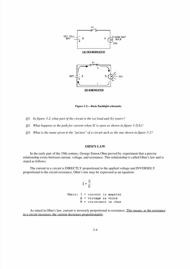
8/6/2019 NEETS MODULE 01 - Introduction to Matter, Energy, And Direct Current
http://slidepdf.com/reader/full/neets-module-01-introduction-to-matter-energy-and-direct-current 110/278
Figure 3-2.—Basic flashlight schematic.
Q1. In figure 3-2, what part of the circuit is the (a) load and (b) source?
Q2. What happens to the path for current when S1 is open as shown in figure 3-2(A)?
Q3. What is the name given to the "picture" of a circuit such as the one shown in figure 3-2?
OHM,S LAW
In the early part of the 19th century, George Simon Ohm proved by experiment that a preciserelationship exists between current, voltage, and resistance. This relationship is called Ohm
,s law and is
stated as follows:
The current in a circuit is DIRECTLY proportional to the applied voltage and INVERSELY
proportional to the circuit resistance. Ohm,s law may be expressed as an equation:
As stated in Ohm,s law, current is inversely proportional to resistance. This means, as the resistance
in a circuit increases, the current decreases proportionately.
3-4

8/6/2019 NEETS MODULE 01 - Introduction to Matter, Energy, And Direct Current
http://slidepdf.com/reader/full/neets-module-01-introduction-to-matter-energy-and-direct-current 111/278
In the equation
if any two quantities are known, the third one can be determined. Refer to figure 3-2(B), theschematic of the flashlight. If the battery (BAT) supplies a voltage of 1.5 volts and the lamp (DS1) has a
resistance of 5 ohms, then the current in the circuit can be determined. Using this equation and
substituting values:
If the flashlight were a two-cell flashlight, we would have twice the voltage, or 3.0 volts, applied to
the circuit. Using this voltage in the equation:
You can see that the current has doubled as the voltage has doubled. This demonstrates that the
current is directly proportional to the applied voltage.
If the value of resistance of the lamp is doubled, the equation will be:
The current has been reduced to one half of the value of the previous equation, or .3 ampere. Thisdemonstrates that the current is inversely proportional to the resistance. Doubling the value of the
resistance of the load reduces circuit current value to one half of its former value.
APPLICATION OF OHM,S LAW
By using Ohm,s law, you are able to find the resistance of a circuit, knowing only the voltage and the
current in the circuit.
In any equation, if all the variables (parameters) are known except one, that unknown can be found.For example, using Ohm
,s law, if current (I) and voltage (E) are known, resistance (R) the only parameter
not known, can be determined:
1. Basic formula:
2. Remove the divisor by multiplying both sides by R:
3-5

8/6/2019 NEETS MODULE 01 - Introduction to Matter, Energy, And Direct Current
http://slidepdf.com/reader/full/neets-module-01-introduction-to-matter-energy-and-direct-current 112/278
3. Result of step 2: R x I = E
4. To get R alone (on one side of the equation) divide both sides by I:
5. The basic formula, transposed for R, is:
Refer to figure 3-3 where E equals 10 volts and I equals 1 ampere. Solve for R, using the equation
just explained.
Given: E = 10 volts
I = 1 ampere
Solution:
Figure 3-3.—Determining resistance in a basic circuit.
3-6

8/6/2019 NEETS MODULE 01 - Introduction to Matter, Energy, And Direct Current
http://slidepdf.com/reader/full/neets-module-01-introduction-to-matter-energy-and-direct-current 113/278
This equation can be used to find the voltage for the circuit shown in figure 3-4.
Figure 3-4.—Determining voltage in a basic circuit.
3-7

8/6/2019 NEETS MODULE 01 - Introduction to Matter, Energy, And Direct Current
http://slidepdf.com/reader/full/neets-module-01-introduction-to-matter-energy-and-direct-current 114/278
The Ohm,s law equation and its various forms may be obtained readily with the aid of figure 3-5.
The circle containing E, I, and R is divided into two parts, with E above the line and with I and R below
the line. To determine the unknown quantity, first cover that quantity with a finger. The position of the
uncovered letters in the circle will indicate the mathematical operation to be performed. For example, to
find I, cover I with a finger. The uncovered letters indicate that E is to be divided by R, or
To find the formula for E, cover E with your finger. The result indicates that I is to be multiplied by
R, or E = IR. To find the formula for R, cover R. The result indicates that E is to be divided by I, or
Figure 3-5.—Ohm,s law in diagram form.
You are cautioned not to rely wholly on the use of this diagram when you transpose the Ohm,s law
formulas. The diagram should be used to supplement your knowledge of the algebraic method. Algebra is
a basic tool in the solution of electrical problems.
Q4. According to Ohm ,s law, what happens to circuit current if the applied voltage (a) increases, (b)
decreases?
Q5. According to Ohm ,s law, what happens to circuit current if circuit resistance (a) increases, (b)
decreases?
Q6. What is the equation used to find circuit resistance if voltage and current values are known?
GRAPHICAL ANALYSIS OF THE BASIC CIRCUIT
One of the most valuable methods of analyzing a circuit is by constructing a graph. No other method
provides a more convenient or more rapid way to observe the characteristics of an electrical device.
3-8

8/6/2019 NEETS MODULE 01 - Introduction to Matter, Energy, And Direct Current
http://slidepdf.com/reader/full/neets-module-01-introduction-to-matter-energy-and-direct-current 115/278
The first step in constructing a graph is to obtain a table of data. The information in the table can beobtained by taking measurements on the circuit under examination, or can be obtained theoretically
through a series of Ohm,s law computations. The latter method is used here.
Since there are three variables (E, I, and R) to be analyzed, there are three distinct graphs that may
be constructed.
To construct any graph of electrical quantities, it is standard practice to vary one quantity in a
specified way and note the changes which occur in a second quantity. The quantity which is intentionally
varied is called the independent variable and is plotted on the horizontal axis. The horizontal axis is
known as the X-AXIS. The second quantity, which varies as a result of changes in the first quantity, is
called the dependent variable and is plotted on the vertical, or Y-AXIS. Any other quantities involved are
held constant.
For example, in the circuit shown in figure 3-6, if the resistance was held at 10 ohms and the voltage
was varied, the resulting changes in current could then be graphed. The resistance is the constant, the
voltage is the independent variable, and the current is the dependent variable.
Figure 3-6.—Three variables in a basic circuit.
Figure 3-7 shows the graph and a table of values. This table shows R held constant at 10 ohms as E
is varied from 0 to 20 volts in 5-volt steps. Through the use of Ohm,s law, you can calculate the value of
current for each value of voltage shown in the table. When the table is complete, the information it
contains can be used to construct the graph shown in figure 3-7. For example, when the voltage applied to
the 10-ohm resistor is 10 volts, the current is 1 ampere. These values of current and voltage determine apoint on the graph. When all five points have been plotted, a smooth curve is drawn through the points.
3-9

8/6/2019 NEETS MODULE 01 - Introduction to Matter, Energy, And Direct Current
http://slidepdf.com/reader/full/neets-module-01-introduction-to-matter-energy-and-direct-current 116/278

8/6/2019 NEETS MODULE 01 - Introduction to Matter, Energy, And Direct Current
http://slidepdf.com/reader/full/neets-module-01-introduction-to-matter-energy-and-direct-current 117/278
This process can be continued for any value of resistance. You can see that as the resistance is
halved, the current is doubled; when the resistance is doubled, the current is halved.
This illustrates another important characteristic of Ohm,s law—current varies inversely with
resistance when the applied voltage is held constant.
Q7. Using the graph in figure 3-7, what is the approximate value of current when the voltage is 12.5
volts?
Q8. Using the graph in figure 3-8, what is the approximate value of current when the resistance is 3ohms?
POWER
Power, whether electrical or mechanical, pertains to the rate at which work is being done. Work is
done whenever a force causes motion. When a mechanical force is used to lift or move a weight, work is
done. However, force exerted WITHOUT causing motion, such as the force of a compressed spring acting
between two fixed objects, does not constitute work.
Previously, it was shown that voltage is an electrical force, and that voltage forces current to flow in
a closed circuit. However, when voltage exists but current does not flow because the circuit is open, nowork is done. This is similar to the spring under tension that produced no motion. When voltage causes
electrons to move, work is done. The instantaneous RATE at which this work is done is called the electric
power rate, and is measured in WATTS.
A total amount of work may be done in different lengths of time. For example, a given number of
electrons may be moved from one point to another in 1 second or in 1 hour, depending on the RATE at
which they are moved. In both cases, total work done is the same. However, when the work is done in a
3-11

8/6/2019 NEETS MODULE 01 - Introduction to Matter, Energy, And Direct Current
http://slidepdf.com/reader/full/neets-module-01-introduction-to-matter-energy-and-direct-current 118/278
short time, the wattage, or INSTANTANEOUS POWER RATE, is greater than when the same amount of
work is done over a longer period of time.
As stated, the basic unit of power is the watt. Power in watts is equal to the voltage across a circuitmultiplied by current through the circuit. This represents the rate at any given instant at which work is
being done. The symbol P indicates electrical power. Thus, the basic power formula is P = E x I, where E
is voltage and I is current in the circuit. The amount of power changes when either voltage or current, orboth voltage and current, are caused to change.
In practice, the ONLY factors that can be changed are voltage and resistance. In explaining the
different forms that formulas may take, current is sometimes presented as a quantity that is changed.
Remember, if current is changed, it is because either voltage or resistance has been changed.
Figure 3-9 shows a basic circuit using a source of power that can be varied from 0 to 8 volts and a
graph that indicates the relationship between voltage and power.
The resistance of this circuit is 2 ohms; this value does not change. Voltage (E) is increased (by
increasing the voltage source), in steps of 1 volt, from 0 volts to 8 volts. By applying Ohm,s law, the
current (I) is determined for each step of voltage. For instance, when E is 1 volt, the current is:
Figure 3-9.—Graph of power related to changing voltage.
3-12

8/6/2019 NEETS MODULE 01 - Introduction to Matter, Energy, And Direct Current
http://slidepdf.com/reader/full/neets-module-01-introduction-to-matter-energy-and-direct-current 119/278
Power (P), in watts, is determined by applying the basic power formula:
and
P = E x I
P = 2 volts x 1 ampere
P = 2 watts
You should notice that when the voltage was increased to 2 volts, the power increased from .5 watts
to 2 watts or 4 times. When the voltage increased to 3 volts, the power increased to 4.5 watts or 9 times.This shows that if the resistance in a circuit is held constant, the power varies directly with the SQUARE
OF THE VOLTAGE.
Another way of proving that power varies as the square of the voltage when resistance is held
constant is:
3-13

8/6/2019 NEETS MODULE 01 - Introduction to Matter, Energy, And Direct Current
http://slidepdf.com/reader/full/neets-module-01-introduction-to-matter-energy-and-direct-current 120/278
Another important relationship may be seen by studying figure 3-10. Thus far, power has been
calculated with voltage and current (P = E x I), and with voltage and resistance
Referring to figure 3-10, note that power also varies as the square of current just as it does with
voltage. Thus, another formula for power, with current and resistance as its factors, is P = I2R. This can
be proved by:
3-14

8/6/2019 NEETS MODULE 01 - Introduction to Matter, Energy, And Direct Current
http://slidepdf.com/reader/full/neets-module-01-introduction-to-matter-energy-and-direct-current 121/278
Figure 3-10.—Graph of power related to changing current.
Up to this point, four of the most important electrical quantities have been discussed. These are
voltage (E), current (I), resistance (R), and power (P). You must understand the relationships which exist
among these quantities because they are used throughout your study of electricity. In the precedingparagraphs, P was expressed in terms of alternate pairs of the other three basic quantities E, I, and R. In
practice, you should be able to express any one of these quantities in terms of any two of the others.
Figure 3-11 is a summary of 12 basic formulas you should know. The four quantities E, I, R, and P
are at the center of the figure. Adjacent to each quantity are three segments. Note that in each segment,
the basic quantity is expressed in terms of two other basic quantities, and no two segments are alike.
3-15

8/6/2019 NEETS MODULE 01 - Introduction to Matter, Energy, And Direct Current
http://slidepdf.com/reader/full/neets-module-01-introduction-to-matter-energy-and-direct-current 122/278
Figure 3-11.—Summary of basic formulas.
For example, the formula wheel in figure 3-11 could be used to find the formula to solve the
following problem:
A circuit has a voltage source that delivers 6 volts and the circuit uses 3 watts of power. What is the
resistance of the load?
Since R is the quantity you have been asked to find, look in the section of the wheel that has R in the
center. The segment
contains the quantities you have been given. The formula you would use is
The problem can now be solved.
3-16

8/6/2019 NEETS MODULE 01 - Introduction to Matter, Energy, And Direct Current
http://slidepdf.com/reader/full/neets-module-01-introduction-to-matter-energy-and-direct-current 123/278
Q9. What is the term applied to the rate at which a mechanical or electrical force causes motion?
Q10. How can the amount of current be changed in a circuit?
Q11. What are the three formulas for electrical power?
POWER RATING
Electrical components are often given a power rating. The power rating, in watts, indicates the rate at
which the device converts electrical energy into another form of energy, such as light, heat, or motion. An
example of such a rating is noted when comparing a 150-watt lamp to a 100-watt lamp. The higher
wattage rating of the 150-watt lamp indicates it is capable of converting more electrical energy into light
energy than the lamp of the lower rating. Other common examples of devices with power ratings are
soldering irons and small electric motors.
In some electrical devices the wattage rating indicates the maximum power the device is designed to
use rather than the normal operating power. A 150-watt lamp, for example, uses 150 watts when operated
at the specified voltage printed on the bulb. In contrast, a device such as a resistor is not normally given a
voltage or a current rating. A resistor is given a power rating in watts and can be operated at any
combination of voltage and current as long as the power rating is not exceeded. In most circuits, the actualpower used by a resistor is considerably less than the power rating of the resistor because a 50% safety
factor is used. For example, if a resistor normally used 2 watts of power, a resistor with a power rating of
3 watts would be used.
Resistors of the same resistance value are available in different wattage values. Carbon resistors, for
example, are commonly made in wattage ratings of 1/8, 1/4, 1/2, 1, and 2 watts. The larger the physical
size of a carbon resistor the higher the wattage rating. This is true because a larger surface area of material
radiates a greater amount of heat more easily.
When resistors with wattage ratings greater than 5 watts are needed, wirewound resistors are used.
Wirewound resistors are made in values between 5 and 200 watts. Special types of wirewound resistors
are used for power in excess of 200 watts.
As with other electrical quantities, prefixes may be attached to the word watt when expressing very
large or very small amounts of power. Some of the more common of these are the kilowatt (1,000 watts),
the megawatt (1,000,000 watts), and the milliwatt (1/1,000 of a watt).
Q12. What is the current in a circuit with 5 ohms of resistance that uses 180 watts of power? (refer to
figure 3-12)
Q13. What type of resistor should be used in the circuit described in question 12?
Q14. What is the power used in a circuit that has 10 amperes of current through a 10-ohm resistor?
3-17
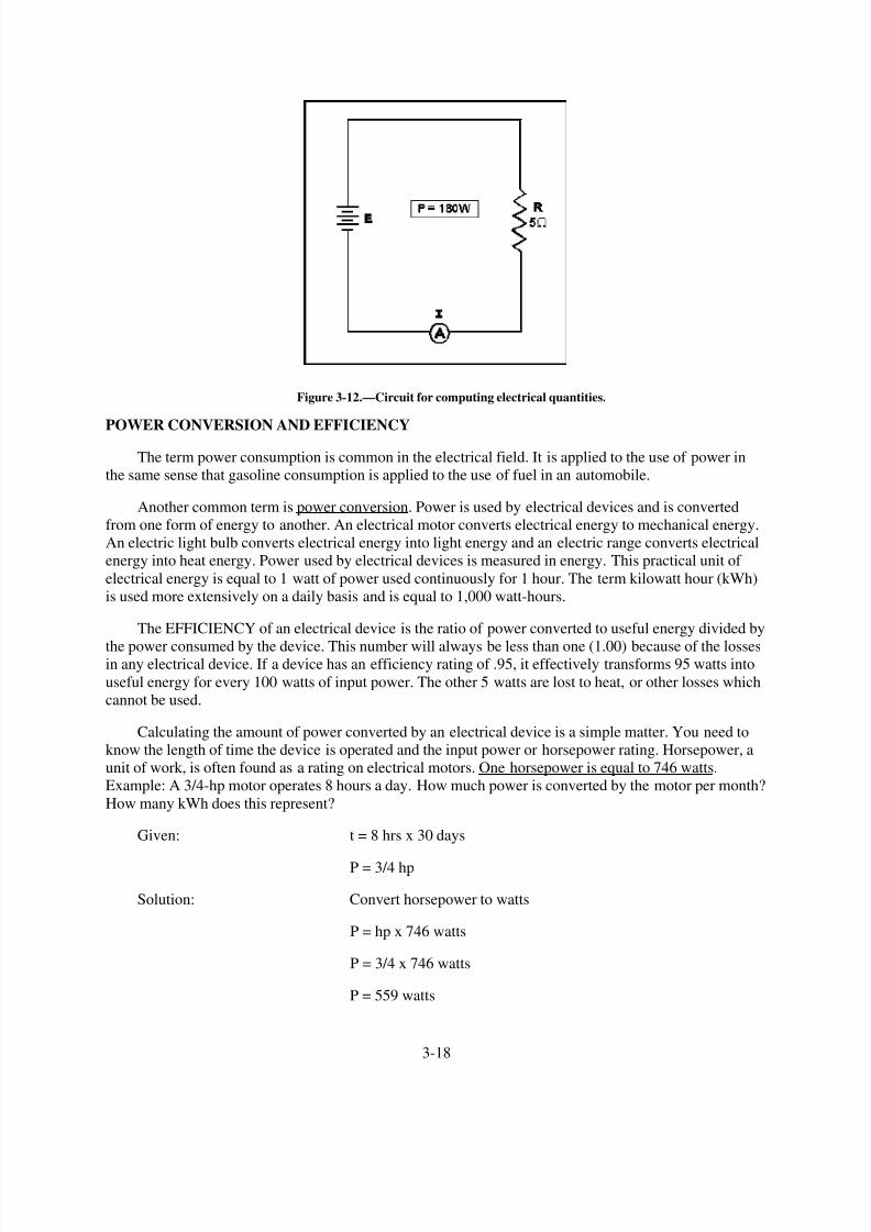
8/6/2019 NEETS MODULE 01 - Introduction to Matter, Energy, And Direct Current
http://slidepdf.com/reader/full/neets-module-01-introduction-to-matter-energy-and-direct-current 124/278
Figure 3-12.—Circuit for computing electrical quantities.
POWER CONVERSION AND EFFICIENCY
The term power consumption is common in the electrical field. It is applied to the use of power in
the same sense that gasoline consumption is applied to the use of fuel in an automobile.
Another common term is power conversion. Power is used by electrical devices and is converted
from one form of energy to another. An electrical motor converts electrical energy to mechanical energy.
An electric light bulb converts electrical energy into light energy and an electric range converts electrical
energy into heat energy. Power used by electrical devices is measured in energy. This practical unit of
electrical energy is equal to 1 watt of power used continuously for 1 hour. The term kilowatt hour (kWh)
is used more extensively on a daily basis and is equal to 1,000 watt-hours.
The EFFICIENCY of an electrical device is the ratio of power converted to useful energy divided by
the power consumed by the device. This number will always be less than one (1.00) because of the lossesin any electrical device. If a device has an efficiency rating of .95, it effectively transforms 95 watts into
useful energy for every 100 watts of input power. The other 5 watts are lost to heat, or other losses which
cannot be used.
Calculating the amount of power converted by an electrical device is a simple matter. You need to
know the length of time the device is operated and the input power or horsepower rating. Horsepower, a
unit of work, is often found as a rating on electrical motors. One horsepower is equal to 746 watts.
Example: A 3/4-hp motor operates 8 hours a day. How much power is converted by the motor per month?
How many kWh does this represent?
Given: t = 8 hrs x 30 days
P = 3/4 hp
Solution: Convert horsepower to watts
P = hp x 746 watts
P = 3/4 x 746 watts
P = 559 watts
3-18

8/6/2019 NEETS MODULE 01 - Introduction to Matter, Energy, And Direct Current
http://slidepdf.com/reader/full/neets-module-01-introduction-to-matter-energy-and-direct-current 125/278
Convert watts to watt-hours
P = work x time
P = 559 watts x 8 x 30
P = 134,000 watt-hours per month
(NOTE: These figures are rounded to the nearest 1000.)
To convert to kWh
If the motor actually uses 137 kWh per month, what is the efficiency of the motor?
Given: Power converted = 134 kWh per month
Power used = 137 kWh per month
Solution:
Q15. How much power is converted by a 1-horsepower motor in 12 hours?
Q16. What is the efficiency of the motor if it actually uses 9.5 kWh in 12 hours?
SERIES DC CIRCUITS
When two unequal charges are connected by a conductor, a complete pathway for current exists. An
electric circuit is a complete conducting pathway. It consists not only of the conductor, but also includes
the path through the voltage source. Inside the voltage source current flows from the positive terminal,
through the source, emerging at the negative terminal.
3-19

8/6/2019 NEETS MODULE 01 - Introduction to Matter, Energy, And Direct Current
http://slidepdf.com/reader/full/neets-module-01-introduction-to-matter-energy-and-direct-current 126/278
SERIES CIRCUIT CHARACTERISTICS
A SERIES CIRCUIT is defined as a circuit that contains only ONE PATH for current flow. To
compare the basic circuit that has been discussed and a more complex series circuit, figure 3-13 shows
two circuits. The basic circuit has only one lamp and the series circuit has three lamps connected in series.
Figure 3-13.—Comparison of basic and series circuits.
Resistance in a Series Circuit
Referring to figure 3-13, the current in a series circuit must flow through each lamp to complete the
electrical path in the circuit. Each additional lamp offers added resistance. In a series circuit, THE
TOTAL CIRCUIT RESISTANCE (RT) IS EQUAL TO THE SUM OF THE INDIVIDUAL
RESISTANCES.
As an equation: RT = R1 + R2 + R3+ . . . R n
NOTE: The subscript n denotes any number of additional resistances that might be in the equation.
Example: In figure 3-14 a series circuit consisting of three resistors: one of 10 ohms, one of 15
ohms, and one of 30 ohms, is shown. A voltage source provides 110 volts. What is the total resistance?
3-20

8/6/2019 NEETS MODULE 01 - Introduction to Matter, Energy, And Direct Current
http://slidepdf.com/reader/full/neets-module-01-introduction-to-matter-energy-and-direct-current 127/278
Figure 3-14.—Solving for total resistance in a series circuit.
In some circuit applications, the total resistance is known and the value of one of the circuit resistors
has to be determined. The equation RT = R1 + R2 + R3 can be transposed to solve for the value of the
unknown resistance.
Example: In figure 3-15 the total resistance of a circuit containing three resistors is 40 ohms. Two of
the circuit resistors are 10 ohms each. Calculate the value of the third resistor (R3).
3-21

8/6/2019 NEETS MODULE 01 - Introduction to Matter, Energy, And Direct Current
http://slidepdf.com/reader/full/neets-module-01-introduction-to-matter-energy-and-direct-current 128/278
Figure 3-15.—Calculating the value of one resistance in a series circuit.
Current in a Series Circuit
Since there is only one path for current in a series circuit, the same current must flow through each
component of the circuit. To determine the current in a series circuit, only the current through one of the
components need be known.
The fact that the same current flows through each component of a series circuit can be verified by
inserting meters into the circuit at various points, as shown in figure 3-16. If this were done, each meter
would be found to indicate the same value of current.
3-22
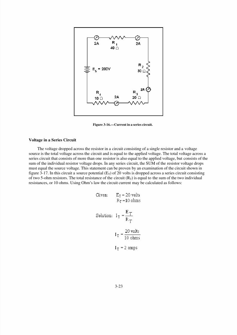
8/6/2019 NEETS MODULE 01 - Introduction to Matter, Energy, And Direct Current
http://slidepdf.com/reader/full/neets-module-01-introduction-to-matter-energy-and-direct-current 129/278
Figure 3-16.—Current in a series circuit.
Voltage in a Series Circuit
The voltage dropped across the resistor in a circuit consisting of a single resistor and a voltage
source is the total voltage across the circuit and is equal to the applied voltage. The total voltage across a
series circuit that consists of more than one resistor is also equal to the applied voltage, but consists of the
sum of the individual resistor voltage drops. In any series circuit, the SUM of the resistor voltage drops
must equal the source voltage. This statement can be proven by an examination of the circuit shown in
figure 3-17. In this circuit a source potential (ET) of 20 volts is dropped across a series circuit consisting
of two 5-ohm resistors. The total resistance of the circuit (RT) is equal to the sum of the two individual
resistances, or 10 ohms. Using Ohm,s law the circuit current may be calculated as follows:
3-23

8/6/2019 NEETS MODULE 01 - Introduction to Matter, Energy, And Direct Current
http://slidepdf.com/reader/full/neets-module-01-introduction-to-matter-energy-and-direct-current 130/278
Figure 3-17.—Calculating individual voltage drops in a series circuit.
Since the value of the resistors is known to be 5 ohms each, and the current through the resistors is
known to be 2 amperes, the voltage drops across the resistors can be calculated. The voltage (E1) across
R1 is therefore:
By inspecting the circuit, you can see that R2 is the same ohmic value as R1 and carries the same
current. The voltage drop across R2 is therefore also equal to 10 volts. Adding these two 10-volts drops
together gives a total drop of 20 volts, exactly equal to the applied voltage. For a series circuit then:
ET = E1 + E 2 + E3 = . . . En
Example: A series circuit consists of three resistors having values of 20 ohms, 30 ohms, and 50
ohms, respectively. Find the applied voltage if the current through the 30 ohm resistor is 2 amps. (The
abbreviation amp is commonly used for ampere.)
To solve the problem, a circuit diagram is first drawn and labeled (fig 3-18).
3-24

8/6/2019 NEETS MODULE 01 - Introduction to Matter, Energy, And Direct Current
http://slidepdf.com/reader/full/neets-module-01-introduction-to-matter-energy-and-direct-current 131/278
Figure 3-18.—Solving for applied voltage in a series circuit.
Substituting:
3-25

8/6/2019 NEETS MODULE 01 - Introduction to Matter, Energy, And Direct Current
http://slidepdf.com/reader/full/neets-module-01-introduction-to-matter-energy-and-direct-current 132/278
NOTE: When you use Ohm,s law, the quantities for the equation MUST be taken from the SAME
part of the circuit. In the above example the voltage across R2 was computed using the current through R2 and the resistance of R2.
The value of the voltage dropped by a resistor is determined by the applied voltage and is in
proportion to the circuit resistances. The voltage drops that occur in a series circuit are in direct
proportion to the resistances. This is the result of having the same current flow through each resistor—thelarger the ohmic value of the resistor, the larger the voltage drop across it.
Q17. A series circuit consisting of three resistors has a current of 3 amps. If R1 = 20 ohms, R2= 60
ohms, and R3 = 80 ohms, what is the (a) total resistance and (b) source voltage of the circuit?
Q18. What is the voltage dropped by each resistor of the circuit described in question 17?
Q19. If the current was increased to 4 amps, what would be the voltage drop across each resistor in the
circuit described in question 17?
Q20. What would have to be done to the circuit described in question 17 to increase the current to 4
amps?
Power in a Series Circuit
Each of the resistors in a series circuit consumes power which is dissipated in the form of heat. Since
this power must come from the source, the total power must be equal to the power consumed by the
circuit resistances. In a series circuit the total power is equal to the SUM of the power dissipated by the
individual resistors. Total power (PT) is equal to:
PT = P1 + P 2 + P3 . . .Pn
Example: A series circuit consists of three resistors having values of 5 ohms, 10 ohms, and 15 ohms.
Find the total power when 120 volts is applied to the circuit. (See fig. 3-19.)
Figure 3-19.—Solving for total power in a series circuit.
3-26

8/6/2019 NEETS MODULE 01 - Introduction to Matter, Energy, And Direct Current
http://slidepdf.com/reader/full/neets-module-01-introduction-to-matter-energy-and-direct-current 133/278
Given:
Solution: The total resistance is found first.
By using the total resistance and the applied voltage, the circuit current is calculated.
By means of the power formulas, the power can be calculated for each resistor:
To check the answer, the total power delivered by the source can be calculated:
3-27

8/6/2019 NEETS MODULE 01 - Introduction to Matter, Energy, And Direct Current
http://slidepdf.com/reader/full/neets-module-01-introduction-to-matter-energy-and-direct-current 134/278

8/6/2019 NEETS MODULE 01 - Introduction to Matter, Energy, And Direct Current
http://slidepdf.com/reader/full/neets-module-01-introduction-to-matter-energy-and-direct-current 135/278
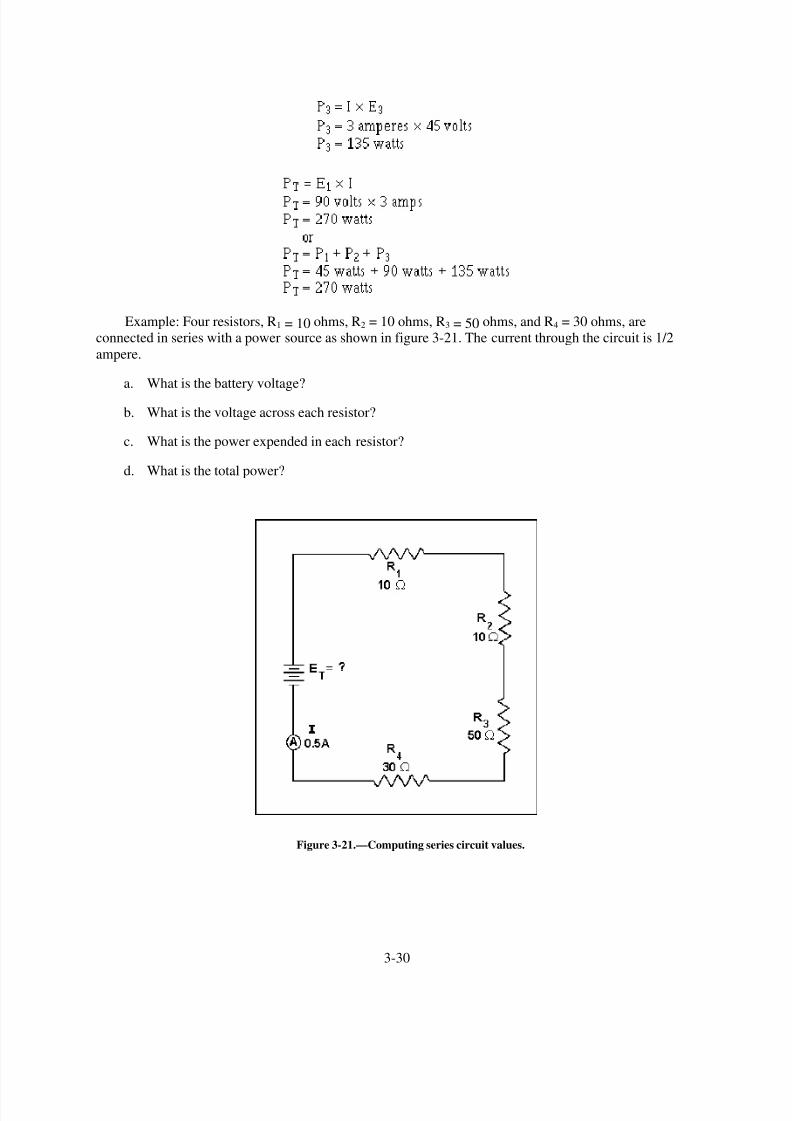
8/6/2019 NEETS MODULE 01 - Introduction to Matter, Energy, And Direct Current
http://slidepdf.com/reader/full/neets-module-01-introduction-to-matter-energy-and-direct-current 136/278
Example: Four resistors, R1 = 10 ohms, R2 = 10 ohms, R3 = 50 ohms, and R4 = 30 ohms, are
connected in series with a power source as shown in figure 3-21. The current through the circuit is 1/2
ampere.
a.
b.
c.
d.
What is the battery voltage?
What is the voltage across each resistor?
What is the power expended in each resistor?
What is the total power?
Figure 3-21.—Computing series circuit values.
3-30

8/6/2019 NEETS MODULE 01 - Introduction to Matter, Energy, And Direct Current
http://slidepdf.com/reader/full/neets-module-01-introduction-to-matter-energy-and-direct-current 137/278
Given:
Solution (a):
Solution (b):
3-31

8/6/2019 NEETS MODULE 01 - Introduction to Matter, Energy, And Direct Current
http://slidepdf.com/reader/full/neets-module-01-introduction-to-matter-energy-and-direct-current 138/278
Solution (c):
Solution (d):
An important fact to keep in mind when applying Ohm,s law to a series circuit is to consider whether
the values used are component values or total values. When the information available enables the use of
Ohm,s law to find total resistance, total voltage, and total current, total values must be inserted into the
formula. To find total resistance:
3-32

8/6/2019 NEETS MODULE 01 - Introduction to Matter, Energy, And Direct Current
http://slidepdf.com/reader/full/neets-module-01-introduction-to-matter-energy-and-direct-current 139/278
To find total voltage:
ET = IT × RT
To find total current:
NOTE: IT is equal to I in a series circuit. However, the distinction between IT and I in the formulashould be noted. The reason for this is that future circuits may have several currents, and it will be
necessary to differentiate between IT and other currents.
To compute any quantity (E, I, R, or P) associated with a single given resistor, the values used in the
formula must be obtained from that particular resistor. For example, to find the value of an unknownresistance, the voltage across and the current through that particular resistor must be used.
To find the value of a resistor:
To find the voltage drop across a resistor:
To find current through a resistor:
Q21. A series circuit consists of two resistors in series. R1 = 25 ohms and R2 = 30 ohms. The circuit
current is 6 amps. What is the (a) source voltage, (b) voltage dropped by each resistor, (c) total
power, and (d) power used by each resistor?
KIRCHHOFF
,
S VOLTAGE LAW
In 1847, G. R. Kirchhoff extended the use of Ohm,s law by developing a simple concept concerning
the voltages contained in a series circuit loop. Kirchhoff ,s voltage law states:
"The algebraic sum of the voltage drops in any closed path in a circuit and the electromotive forces
in that path is equal to zero."
3-33

8/6/2019 NEETS MODULE 01 - Introduction to Matter, Energy, And Direct Current
http://slidepdf.com/reader/full/neets-module-01-introduction-to-matter-energy-and-direct-current 140/278
To state Kirchhoff ,s law another way, the voltage drops and voltage sources in a circuit are equal at
any given moment in time. If the voltage sources are assumed to have one sign (positive or negative) at
that instant and the voltage drops are assumed to have the opposite sign, the result of adding the voltage
sources and voltage drops will be zero.
NOTE: The terms electromotive force and emf are used when explaining Kirchhoff ,s law because
Kirchhoff ,s law is used in alternating current circuits (covered in Module 2). In applying Kirchhoff
,s law
to direct current circuits, the terms electromotive force and emf apply to voltage sources such as batteries
or power supplies.
Through the use of Kirchhoff ,s law, circuit problems can be solved which would be difficult, and
often impossible, with knowledge of Ohm,s law alone. When Kirchhoff
,s law is properly applied, an
equation can be set up for a closed loop and the unknown circuit values can be calculated.
POLARITY OF VOLTAGE
To apply Kirchhoff ,s voltage law, the meaning of voltage polarity must be understood.
In the circuit shown in figure 3-22, the current is shown flowing in a counterclockwise direction.
Notice that the end of resistor R1, into which the current flows, is marked NEGATIVE ( ). The end of R1 at which the current leaves is marked POSITIVE (+). These polarity markings are used to show that the
end of R1 into which the current flows is at a higher negative potential than the end of the resistor at
which the current leaves. Point A is more negative than point B.
Figure 3-22.—Voltage polarities.
Point C, which is at the same potential as point B, is labeled negative. This is to indicate that point C
is more negative than point D. To say a point is positive (or negative) without stating what the polarity is
based upon has no meaning. In working with Kirchhoff ,s law, positive and negative polarities are
assigned in the direction of current flow.
3-34
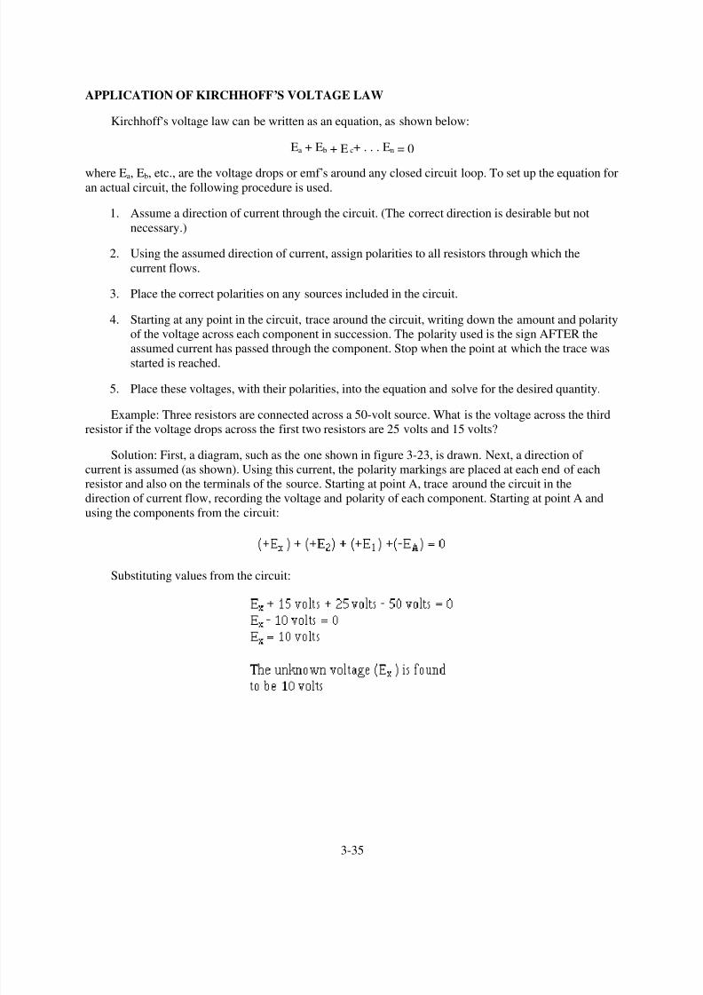
8/6/2019 NEETS MODULE 01 - Introduction to Matter, Energy, And Direct Current
http://slidepdf.com/reader/full/neets-module-01-introduction-to-matter-energy-and-direct-current 141/278
APPLICATION OF KIRCHHOFF,S VOLTAGE LAW
Kirchhoff ,s voltage law can be written as an equation, as shown below:
Ea + Eb + E c+ . . . En = 0
where Ea, Eb, etc., are the voltage drops or emf ,s around any closed circuit loop. To set up the equation for
an actual circuit, the following procedure is used.
1.
2.
3.
4.
5.
Assume a direction of current through the circuit. (The correct direction is desirable but not
necessary.)
Using the assumed direction of current, assign polarities to all resistors through which the
current flows.
Place the correct polarities on any sources included in the circuit.
Starting at any point in the circuit, trace around the circuit, writing down the amount and polarity
of the voltage across each component in succession. The polarity used is the sign AFTER the
assumed current has passed through the component. Stop when the point at which the trace wasstarted is reached.
Place these voltages, with their polarities, into the equation and solve for the desired quantity.
Example: Three resistors are connected across a 50-volt source. What is the voltage across the third
resistor if the voltage drops across the first two resistors are 25 volts and 15 volts?
Solution: First, a diagram, such as the one shown in figure 3-23, is drawn. Next, a direction of
current is assumed (as shown). Using this current, the polarity markings are placed at each end of each
resistor and also on the terminals of the source. Starting at point A, trace around the circuit in the
direction of current flow, recording the voltage and polarity of each component. Starting at point A and
using the components from the circuit:
Substituting values from the circuit:
3-35
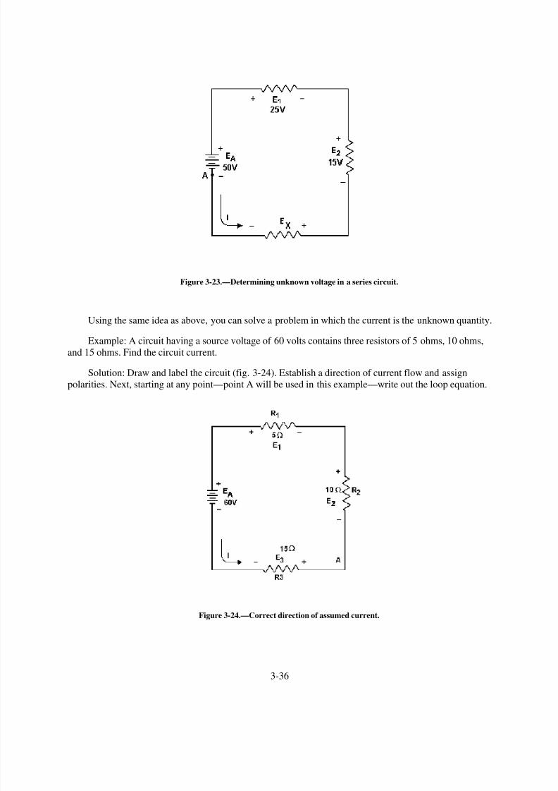
8/6/2019 NEETS MODULE 01 - Introduction to Matter, Energy, And Direct Current
http://slidepdf.com/reader/full/neets-module-01-introduction-to-matter-energy-and-direct-current 142/278
Figure 3-23.—Determining unknown voltage in a series circuit.
Using the same idea as above, you can solve a problem in which the current is the unknown quantity.
Example: A circuit having a source voltage of 60 volts contains three resistors of 5 ohms, 10 ohms,
and 15 ohms. Find the circuit current.
Solution: Draw and label the circuit (fig. 3-24). Establish a direction of current flow and assign
polarities. Next, starting at any point—point A will be used in this example—write out the loop equation.
Figure 3-24.—Correct direction of assumed current.
3-36

8/6/2019 NEETS MODULE 01 - Introduction to Matter, Energy, And Direct Current
http://slidepdf.com/reader/full/neets-module-01-introduction-to-matter-energy-and-direct-current 143/278
Since the current obtained in the above calculations is a positive 2 amps, the assumed direction of
current was correct. To show what happens if the incorrect direction of current is assumed, the problem
will be solved as before, but with the opposite direction of current. The circuit is redrawn showing the
new direction of current and new polarities in figure 3-25. Starting at point A the loop equation is:
3-37

8/6/2019 NEETS MODULE 01 - Introduction to Matter, Energy, And Direct Current
http://slidepdf.com/reader/full/neets-module-01-introduction-to-matter-energy-and-direct-current 144/278

8/6/2019 NEETS MODULE 01 - Introduction to Matter, Energy, And Direct Current
http://slidepdf.com/reader/full/neets-module-01-introduction-to-matter-energy-and-direct-current 145/278
Figure 3-26.—Aiding and opposing sources.
A simple solution may be obtained for a multiple-source circuit through the use of Kirchhoff ,s
voltage law. In applying this method, the same procedure is used for the multiple-source circuit as was
used above for the single-source circuit. This is demonstrated by the following example.
Example: Using Kirchhoff ,s voltage equation, find the amount of current in the circuit shown in
fig 3-27.
Figure 3-27.—Solving for circuit current using Kirchhoff ,s voltage equation.
3-39

8/6/2019 NEETS MODULE 01 - Introduction to Matter, Energy, And Direct Current
http://slidepdf.com/reader/full/neets-module-01-introduction-to-matter-energy-and-direct-current 146/278
Solution: As before, a direction of current flow is assumed and polarity signs are placed on the
drawing. The loop equation will be started at point A.
E2 + ER1 + E 1 + E3 + ER2 = 0
Q22. When using Kirchhoff ,s voltage law, how are voltage polarities assigned to the voltage drops
across resistors?
Q23. Refer to figure 3-27, if R1was changed to a 40-ohm resistor, what would be the value of circuit
current (I T )?
Q24. Refer to figure 3-27. What is the effective source voltage of the circuit using the 40-ohm resistor?
CIRCUIT TERMS AND CHARACTERISTICS
Before you learn about the types of circuits other than the series circuit, you should become familiar
with some of the terms and characteristics used in electrical circuits. These terms and characteristics will
be used throughout your study of electricity and electronics.
REFERENCE POINT
A reference point is an arbitrarily chosen point to which all other points in the circuit are compared.In series circuits, any point can be chosen as a reference and the electrical potential at all other points can
be determined in reference to that point. In figure 3-28 point A shall be considered the reference point.
Each series resistor in the illustrated circuit is of equal value. The applied voltage is equally distributed
across each resistor. The potential at point B is 25 volts more positive than at point A. Points C and D are
50 volts and 75 volts more positive than point A respectively.
3-40
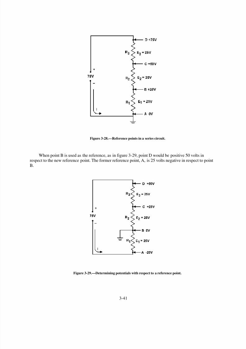
8/6/2019 NEETS MODULE 01 - Introduction to Matter, Energy, And Direct Current
http://slidepdf.com/reader/full/neets-module-01-introduction-to-matter-energy-and-direct-current 147/278
Figure 3-28.—Reference points in a series circuit.
When point B is used as the reference, as in figure 3-29, point D would be positive 50 volts in
respect to the new reference point. The former reference point, A, is 25 volts negative in respect to point
B.
Figure 3-29.—Determining potentials with respect to a reference point.
3-41

8/6/2019 NEETS MODULE 01 - Introduction to Matter, Energy, And Direct Current
http://slidepdf.com/reader/full/neets-module-01-introduction-to-matter-energy-and-direct-current 148/278
As in the previous circuit illustration, the reference point of a circuit is always considered to be atzero potential. Since the earth (ground) is said to be at a zero potential, the term GROUND is used to
denote a common electrical point of zero potential. In figure 3-30, point A is the zero reference, or
ground, and the symbol for ground is shown connected to point A. Point C is 75 volts positive in respect
to ground.
Figure 3-30.—Use of ground symbols.
In most electrical equipment, the metal chassis is the common ground for the many electrical
circuits. When each electrical circuit is completed, common points of a circuit at zero potential are
connected directly to the metal chassis, thereby eliminating a large amount of connecting wire. Theelectrons pass through the metal chassis (a conductor) to reach other points of the circuit. An example of a
chassis grounded circuit is illustrated in figure 3-31.
3-42

8/6/2019 NEETS MODULE 01 - Introduction to Matter, Energy, And Direct Current
http://slidepdf.com/reader/full/neets-module-01-introduction-to-matter-energy-and-direct-current 149/278
Figure 3-31.—Ground used as a conductor.
Most voltage measurements used to check proper circuit operation in electrical equipment are taken
in respect to ground. One meter lead is attached to a grounded point and the other meter lead is moved to
various test points. Circuit measurement is explained in more detail in NEETS Module 3.
OPEN CIRCUIT
A circuit is said to be OPEN when a break exists in a complete conducting pathway. Although an
open occurs when a switch is used to deenergize a circuit, an open may also develop accidentally. To
restore a circuit to proper operation, the open must be located, its cause determined, and repairs made.
Sometimes an open can be located visually by a close inspection of the circuit components.
Defective components, such as burned out resistors, can usually be discovered by this method. Others,
such as a break in wire covered by insulation or the melted element of an enclosed fuse, are not visible to
the eye. Under such conditions, the understanding of the effect an open has on circuit conditions enables a
technician to make use of test equipment to locate the open component.
In figure 3-32, the series circuit consists of two resistors and a fuse. Notice the effects on circuit
conditions when the fuse opens.
3-43

8/6/2019 NEETS MODULE 01 - Introduction to Matter, Energy, And Direct Current
http://slidepdf.com/reader/full/neets-module-01-introduction-to-matter-energy-and-direct-current 150/278

8/6/2019 NEETS MODULE 01 - Introduction to Matter, Energy, And Direct Current
http://slidepdf.com/reader/full/neets-module-01-introduction-to-matter-energy-and-direct-current 151/278
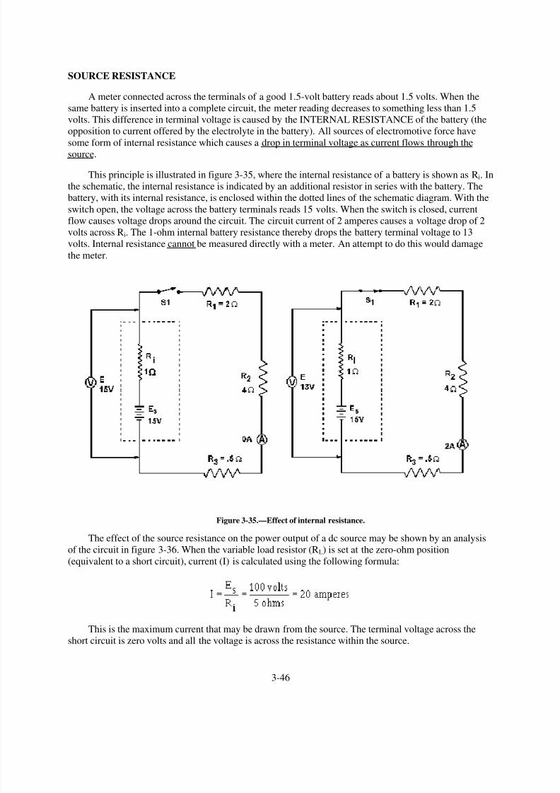
8/6/2019 NEETS MODULE 01 - Introduction to Matter, Energy, And Direct Current
http://slidepdf.com/reader/full/neets-module-01-introduction-to-matter-energy-and-direct-current 152/278
SOURCE RESISTANCE
A meter connected across the terminals of a good 1.5-volt battery reads about 1.5 volts. When the
same battery is inserted into a complete circuit, the meter reading decreases to something less than 1.5
volts. This difference in terminal voltage is caused by the INTERNAL RESISTANCE of the battery (the
opposition to current offered by the electrolyte in the battery). All sources of electromotive force have
some form of internal resistance which causes a drop in terminal voltage as current flows through the
source.
This principle is illustrated in figure 3-35, where the internal resistance of a battery is shown as Ri. In
the schematic, the internal resistance is indicated by an additional resistor in series with the battery. The
battery, with its internal resistance, is enclosed within the dotted lines of the schematic diagram. With the
switch open, the voltage across the battery terminals reads 15 volts. When the switch is closed, current
flow causes voltage drops around the circuit. The circuit current of 2 amperes causes a voltage drop of 2
volts across Ri. The 1-ohm internal battery resistance thereby drops the battery terminal voltage to 13
volts. Internal resistance cannot be measured directly with a meter. An attempt to do this would damage
the meter.
Figure 3-35.—Effect of internal resistance.
The effect of the source resistance on the power output of a dc source may be shown by an analysis
of the circuit in figure 3-36. When the variable load resistor (RL) is set at the zero-ohm position
(equivalent to a short circuit), current (I) is calculated using the following formula:
This is the maximum current that may be drawn from the source. The terminal voltage across the
short circuit is zero volts and all the voltage is across the resistance within the source.
3-46

8/6/2019 NEETS MODULE 01 - Introduction to Matter, Energy, And Direct Current
http://slidepdf.com/reader/full/neets-module-01-introduction-to-matter-energy-and-direct-current 153/278
Figure 3-36.—Effect of source resistance on power output.
3-47

8/6/2019 NEETS MODULE 01 - Introduction to Matter, Energy, And Direct Current
http://slidepdf.com/reader/full/neets-module-01-introduction-to-matter-energy-and-direct-current 154/278
If the load resistance (RL) were increased (the internal resistance remaining the same), the currentdrawn from the source would decrease. Consequently, the voltage drop across the internal resistance
would decrease. At the same time, the terminal voltage applied across the load would increase and
approach a maximum as the current approaches zero amps.
POWER TRANSFER AND EFFICIENCY
Maximum power is transferred from the source to the load when the resistance of the load is equal to
the internal resistance of the source. This theory is illustrated in the table and the graph of figure 3-36.
When the load resistance is 5 ohms, matching the source resistance, the maximum power of 500 watts is
developed in the load.
The efficiency of power transfer (ratio of output power to input power) from the source to the load
increases as the load resistance is increased. The efficiency approaches 100 percent as the load resistance
approaches a relatively large value compared with that of the source, since less power is lost in the source.
The efficiency of power transfer is only 50 percent at the maximum power transfer point (when the load
resistance equals the internal resistance of the source). The efficiency of power transfer approaches zero
efficiency when the load resistance is relatively small compared with the internal resistance of the source.
This is also shown on the chart of figure 3-36.
The problem of a desire for both high efficiency and maximum power transfer is resolved by a
compromise between maximum power transfer and high efficiency. Where the amounts of power
involved are large and the efficiency is important, the load resistance is made large relative to the source
resistance so that the losses are kept small. In this case, the efficiency is high. Where the problem of
matching a source to a load is important, as in communications circuits, a strong signal may be more
important than a high percentage of efficiency. In such cases, the efficiency of power transfer should be
only about 50 percent; however, the power transfer would be the maximum which the source is capable of
supplying.
You should now understand the basic concepts of series circuits. The principles which have been
presented are of lasting importance. Once equipped with a firm understanding of series circuits, you hold
the key to an understanding of the parallel circuits to be presented next.
Q25. A circuit has a source voltage of 100 volts and two 50-ohm resistors connected in series. If the
reference point for this circuit is placed between the two resistors, what would be the voltage at
the reference point?
Q26. If the reference point in question 25 were connected to ground, what would be the voltage level of
the reference point?
Q27. What is an open circuit?
Q28. What is a short circuit?
Q29. Why will a meter indicate more voltage at the battery terminal when the battery is out of a circuitthan when the battery is in a circuit?
Q30. What condition gives maximum power transfer from the source to the load?
Q31. What is the efficiency of power transfer in question 30?
Q32. A circuit has a source voltage of 25 volts. The source resistance is 1 ohm and the load resistance
is 49 ohms. What is the efficiency of power transfer?
3-48

8/6/2019 NEETS MODULE 01 - Introduction to Matter, Energy, And Direct Current
http://slidepdf.com/reader/full/neets-module-01-introduction-to-matter-energy-and-direct-current 155/278
PARALLEL DC CIRCUITS
The discussion of electrical circuits presented up to this point has been concerned with series circuits
in which there is only one path for current. There is another basic type of circuit known as the
PARALLEL CIRCUIT with which you must become familiar. Where the series circuit has only one path
for current, the parallel circuit has more than one path for current.
Ohm,s law and Kirchhoff
,s law apply to all electrical circuits, but the characteristics of a parallel dc
circuit are different than those of a series dc circuit.
PARALLEL CIRCUIT CHARACTERISTICS
A PARALLEL CIRCUIT is defined as one having more than one current path connected to a
common voltage source. Parallel circuits, therefore, must contain two or more resistances which are not
connected in series. An example of a basic parallel circuit is shown in figure 3-37.
Figure 3-37.—Example of a basic parallel circuit.
Start at the voltage source (Es) and trace counterclockwise around the circuit. Two complete and
separate paths can be identified in which current can flow. One path is traced from the source, through
resistance R1, and back to the source. The other path is from the source, through resistance R2, and back to
the source.
Voltage in a Parallel Circuit
You have seen that the source voltage in a series circuit divides proportionately across each resistor
in the circuit. IN A PARALLEL CIRCUIT, THE SAME VOLTAGE IS PRESENT IN EACH BRANCH.
(A branch is a section of a circuit that has a complete path for current.) In figure 3-37 this voltage is equal
to the applied voltage (Es). This can be expressed in equation form as:
ES = ER1 = E R2
Voltage measurements taken across the resistors of a parallel circuit, as illustrated by figure 3-38
verify this equation. Each meter indicates the same amount of voltage. Notice that the voltage across each
resistor is the same as the applied voltage.
3-49

8/6/2019 NEETS MODULE 01 - Introduction to Matter, Energy, And Direct Current
http://slidepdf.com/reader/full/neets-module-01-introduction-to-matter-energy-and-direct-current 156/278
Figure 3-38.—Voltage comparison in a parallel circuit.
Example: Assume that the current through a resistor of a parallel circuit is known to be 4.5
milliamperes (4.5 mA) and the value of the resistor is 30,000 ohms (30 k Ω). Determine the source
voltage. The circuit is shown in figure 3-39.
Given:
Solution:
Figure 3-39.—Example problem parallel circuit.
3-50

8/6/2019 NEETS MODULE 01 - Introduction to Matter, Energy, And Direct Current
http://slidepdf.com/reader/full/neets-module-01-introduction-to-matter-energy-and-direct-current 157/278
Since the source voltage is equal to the voltage of a branch:
To simplify the math operation, the values can be expressed in powers of ten as follows:
If you are not familiar with the use of the powers of 10 or would like to brush up on it, Mathematics,
Vol. 1, NAVEDTRA 10069-C, will be of great help to you.
Q33. What would the source voltage (E S ) in figure 3-39 be if the current through R2 were 2 milliamps?
Current in a Parallel Circuit
Ohm,s law states that the current in a circuit is inversely proportional to the circuit resistance. Thisfact is true in both series and parallel circuits.
There is a single path for current in a series circuit. The amount of current is determined by the total
resistance of the circuit and the applied voltage. In a parallel circuit the source current divides among the
available paths.
The behavior of current in parallel circuits will be shown by a series of illustrations using example
circuits with different values of resistance for a given value of applied voltage.
Part (A) of figure 3-40 shows a basic series circuit. Here, the total current must pass through the
single resistor. The amount of current can be determined.
3-51

8/6/2019 NEETS MODULE 01 - Introduction to Matter, Energy, And Direct Current
http://slidepdf.com/reader/full/neets-module-01-introduction-to-matter-energy-and-direct-current 158/278
Figure 3-40.—Analysis of current in parallel circuit.
Given:
Solution:
Part (B) of figure 3-40 shows the same resistor (R1) with a second resistor (R2) of equal value
connected in parallel across the voltage source. When Ohm,s law is applied, the current flow through each
resistor is found to be the same as the current through the single resistor in part (A).
3-52

8/6/2019 NEETS MODULE 01 - Introduction to Matter, Energy, And Direct Current
http://slidepdf.com/reader/full/neets-module-01-introduction-to-matter-energy-and-direct-current 159/278
Given:
Solution:
It is apparent that if there is 5 amperes of current through each of the two resistors, there must be a
TOTAL CURRENT of 10 amperes drawn from the source.
The total current of 10 amperes, as illustrated in figure 3-40(B), leaves the negative terminal of the
battery and flows to point a. Since point a is a connecting point for the two resistors, it is called a
JUNCTION. At junction a, the total current divides into two currents of 5 amperes each. These two
currents flow through their respective resistors and rejoin at junction b. The total current then flows from
junction b back to the positive terminal of the source. The source supplies a total current of 10 amperes
and each of the two equal resistors carries one-half the total current.
Each individual current path in the circuit of figure 3-40(B) is referred to as a BRANCH. Each
branch carries a current that is a portion of the total current. Two or more branches form a NETWORK.
From the previous explanation, the characteristics of current in a parallel circuit can be expressed in
terms of the following general equation:
IT = I1 + I 2 + . . . In
3-53

8/6/2019 NEETS MODULE 01 - Introduction to Matter, Energy, And Direct Current
http://slidepdf.com/reader/full/neets-module-01-introduction-to-matter-energy-and-direct-current 160/278
Compare part (A) of figure 3-41 with part (B) of the circuit in figure 3-40. Notice that doubling thevalue of the second branch resistor (R2) has no effect on the current in the first branch (IR1), but does
reduce the second branch current (IR2) to one-half its original value. The total circuit current drops to a
value equal to the sum of the branch currents. These facts are verified by the following equations.
Given:
Solution:
3-54

8/6/2019 NEETS MODULE 01 - Introduction to Matter, Energy, And Direct Current
http://slidepdf.com/reader/full/neets-module-01-introduction-to-matter-energy-and-direct-current 161/278
Figure 3-41.—Current behavior in parallel circuits.
The amount of current flow in the branch circuits and the total current in the circuit shown in figure
3-41(B) are determined by the following computations.
Given:
3-55

8/6/2019 NEETS MODULE 01 - Introduction to Matter, Energy, And Direct Current
http://slidepdf.com/reader/full/neets-module-01-introduction-to-matter-energy-and-direct-current 162/278

8/6/2019 NEETS MODULE 01 - Introduction to Matter, Energy, And Direct Current
http://slidepdf.com/reader/full/neets-module-01-introduction-to-matter-energy-and-direct-current 163/278
"The algebraic sum of the currents entering and leaving any junction of conductors is equal to zero."
This law can be stated mathematically as:
Ia + lb + . . . I n = 0
where: Ia, I
b, etc., are the currents entering and leaving the junction. Currents ENTERING the
junction are considered to be POSITIVE and currents LEAVING the junction are considered to be
NEGATIVE. When solving a problem using Kirchhoff ,s current law, the currents must be placed into the
equation WITH THE PROPER POLARITY SIGNS ATTACHED.
Example: Solve for the value of I3 in figure 3-42.
Given:
Solution:
Ia + lb + . . . I a = 0
Figure 3-42.—Circuit for example problem.
The currents are placed into the equation with the proper signs.
3-57

8/6/2019 NEETS MODULE 01 - Introduction to Matter, Energy, And Direct Current
http://slidepdf.com/reader/full/neets-module-01-introduction-to-matter-energy-and-direct-current 164/278
I3 has a value of 2 amperes, and the negative sign shows it to be a current LEAVING the junction.
Example. Using figure 3-43, solve for the magnitude and direction of I3.
Figure 3-43.—Circuit for example problem.
Given:
Solution:
3-58

8/6/2019 NEETS MODULE 01 - Introduction to Matter, Energy, And Direct Current
http://slidepdf.com/reader/full/neets-module-01-introduction-to-matter-energy-and-direct-current 165/278
I3 is 2 amperes and its positive sign shows it to be a current entering the junction.
Q34. There is a relationship between total current and current through the individual components in a
circuit. What is this relationship in a series circuit and a parallel circuit?
Q35. In applying Kirchhoff ,s current law, what does the polarity of the current indicate?
Resistance in a Parallel Circuit
In the example diagram, figure 3-44, there are two resistors connected in parallel across a 5-volt
battery. Each has a resistance value of 10 ohms. A complete circuit consisting of two parallel paths is
formed and current flows as shown.
Figure 3-44.—Two equal resistors connected in parallel.
Computing the individual currents shows that there is one-half of an ampere of current through each
resistance. The total current flowing from the battery to the junction of the resistors, and returning from
the resistors to the battery, is equal to 1 ampere.
The total resistance of the circuit can be calculated by using the values of total voltage (ET) and total
current (IT).
NOTE: From this point on the abbreviations and symbology for electrical quantities will be used in
example problems.
Given:
3-59

8/6/2019 NEETS MODULE 01 - Introduction to Matter, Energy, And Direct Current
http://slidepdf.com/reader/full/neets-module-01-introduction-to-matter-energy-and-direct-current 166/278
Solution:
This computation shows the total resistance to be 5 ohms; one-half the value of either of the two
resistors.
Since the total resistance of a parallel circuit is smaller than any of the individual resistors, total
resistance of a parallel circuit is not the sum of the individual resistor values as was the case in a series
circuit. The total resistance of resistors in parallel is also referred to as EQUIVALENT RESISTANCE
(Req). The terms total resistance and equivalent resistance are used interchangeably.
There are several methods used to determine the equivalent resistance of parallel circuits. The best
method for a given circuit depends on the number and value of the resistors. For the circuit described
above, where all resistors have the same value, the following simple equation is used:
This equation is valid for any number of parallel resistors of EQUAL VALUE.
Example: Four 40-ohm resistors are connected in parallel. What is their equivalent resistance?
Given:
Solution:
3-60

8/6/2019 NEETS MODULE 01 - Introduction to Matter, Energy, And Direct Current
http://slidepdf.com/reader/full/neets-module-01-introduction-to-matter-energy-and-direct-current 167/278
Figure 3-45 shows two resistors of unequal value in parallel. Since the total current is shown, the
equivalent resistance can be calculated.
Figure 3-45.—Example circuit with unequal parallel resistors.
Given:
Solution:
The equivalent resistance of the circuit shown in figure 3-45 is smaller than either of the two
resistors (R1, R2). An important point to remember is that the equivalent resistance of a parallel circuit is
always less than the resistance of any branch.
Equivalent resistance can be found if you know the individual resistance values and the source
voltage. By calculating each branch current, adding the branch currents to calculate total current, and
dividing the source voltage by the total current, the total can be found. This method, while effective, is
somewhat lengthy. A quicker method of finding equivalent resistance is to use the general formula forresistors in parallel:
If you apply the general formula to the circuit shown in figure 3-45 you will get the same value for
equivalent resistance (2Ω) as was obtained in the previous calculation that used source voltage and total
current.
3-61

8/6/2019 NEETS MODULE 01 - Introduction to Matter, Energy, And Direct Current
http://slidepdf.com/reader/full/neets-module-01-introduction-to-matter-energy-and-direct-current 168/278

8/6/2019 NEETS MODULE 01 - Introduction to Matter, Energy, And Direct Current
http://slidepdf.com/reader/full/neets-module-01-introduction-to-matter-energy-and-direct-current 169/278
This formula is used to solve for the equivalent resistance of a number of unequal parallel resistors.You must find the lowest common denominator in solving these problems. If you are a little hazy on
finding the lowest common denominator, brush up on it in Mathematics Volume 1, NAVEDTRA 10069
(Series).
Example: Three resistors are connected in parallel as shown in figure 3-46. The resistor values are:
R1 = 20 ohms, R2 = 30 ohms, R3 = 40 ohms. What is the equivalent resistance? (Use the reciprocalmethod.)
Figure 3-46.—Example parallel circuit with unequal branch resistors.
Given:
3-63

8/6/2019 NEETS MODULE 01 - Introduction to Matter, Energy, And Direct Current
http://slidepdf.com/reader/full/neets-module-01-introduction-to-matter-energy-and-direct-current 170/278
Solution:
PRODUCT OVER THE SUM METHOD.—A convenient method for finding the equivalent, or
total, resistance of two parallel resistors is by using the following formula.
This equation, called the product over the sum formula, is used so frequently it should be committed
to memory.
Example: What is the equivalent resistance of a 20-ohm and a 30-ohm resistor connected in parallel,
as in figure 3-47?
Figure 3-47.—Parallel circuit with two unequal resistors.
3-64

8/6/2019 NEETS MODULE 01 - Introduction to Matter, Energy, And Direct Current
http://slidepdf.com/reader/full/neets-module-01-introduction-to-matter-energy-and-direct-current 171/278
Given:
Solution:
Q36. Four equal resistors are connected in parallel, each resistor has an ohmic value of 100 ohms,what is the equivalent resistance?
Q37. Three resistors connected in parallel have values of 12 k Ω , 20 k Ω , and 30 k Ω. What is the
equivalent resistance?
Q38. Two resistors connected in parallel have values of 10 k Ω and 30 k Ω. What is the equivalent
resistance?
Power in a Parallel Circuit
Power computations in a parallel circuit are essentially the same as those used for the series circuit.
Since power dissipation in resistors consists of a heat loss, power dissipations are additive regardless of
how the resistors are connected in the circuit. The total power is equal to the sum of the power dissipatedby the individual resistors. Like the series circuit, the total power consumed by the parallel circuit is:
Example: Find the total power consumed by the circuit in figure 3-48.
3-65

8/6/2019 NEETS MODULE 01 - Introduction to Matter, Energy, And Direct Current
http://slidepdf.com/reader/full/neets-module-01-introduction-to-matter-energy-and-direct-current 172/278
Figure 3-48.—Example parallel circuit.
Given:
Solution:
3-66

8/6/2019 NEETS MODULE 01 - Introduction to Matter, Energy, And Direct Current
http://slidepdf.com/reader/full/neets-module-01-introduction-to-matter-energy-and-direct-current 173/278
Since the total current and source voltage are known, the total power can also be computed by:
Given:
Solution:
Equivalent Circuits
In the study of electricity, it is often necessary to reduce a complex circuit into a simpler form. Any
complex circuit consisting of resistances can be redrawn (reduced) to a basic equivalent circuit containing
the voltage source and a single resistor representing total resistance. This process is called reduction to an
EQUIVALENT CIRCUIT.
Figure 3-49 shows a parallel circuit with three resistors of equal value and the redrawn equivalent
circuit. The parallel circuit shown in part A shows the original circuit. To create the equivalent circuit,
you must first calculate the equivalent resistance.
3-67

8/6/2019 NEETS MODULE 01 - Introduction to Matter, Energy, And Direct Current
http://slidepdf.com/reader/full/neets-module-01-introduction-to-matter-energy-and-direct-current 174/278
Figure 3-49.—Parallel circuit with equivalent circuit.
Given:
Solution:
Once the equivalent resistance is known, a new circuit is drawn consisting of a single resistor (to
represent the equivalent resistance) and the voltage source, as shown in part B.
Rules for Parallel DC Circuits
1. The same voltage exists across each branch of a parallel circuit and is equal to the source
voltage.
3-68

8/6/2019 NEETS MODULE 01 - Introduction to Matter, Energy, And Direct Current
http://slidepdf.com/reader/full/neets-module-01-introduction-to-matter-energy-and-direct-current 175/278
2.
3.
4.
The current through a branch of a parallel network is inversely proportional to the amount of
resistance of the branch.
The total current of a parallel circuit is equal to the sum of the individual branch currents of the
circuit.
The total resistance of a parallel circuit is found by the general formula:
or one of the formulas derived from this general formula.
5. The total power consumed in a parallel circuit is equal to the sum of the power consumptions of
the individual resistances.
SOLVING PARALLEL CIRCUIT PROBLEMS
Problems involving the determination of resistance, voltage, current, and power in a parallel circuitare solved as simply as in a series circuit. The procedure is the same — (1) draw the circuit diagram, (2)
state the values given and the values to be found, (3) select the equations to be used in solving for the
unknown quantities based upon the known quantities, and (4) substitute the known values in the equation
you have selected and solve for the unknown value.
Example: A parallel circuit consists of five resistors. The value of each resistor is known and the
current through R1 is known. You are asked to calculate the value for total resistance, total power, total
current, source voltage, the power used by each resistor, and the current through resistors R2, R3, R4, and
R5.
Given:
Find:
This may appear to be a large amount of mathematical manipulation. However, if you use the step-
by-step approach, the circuit will fall apart quite easily.
The first step in solving this problem is for you to draw the circuit and indicate the known values as
shown in figure 3-50.
3-69

8/6/2019 NEETS MODULE 01 - Introduction to Matter, Energy, And Direct Current
http://slidepdf.com/reader/full/neets-module-01-introduction-to-matter-energy-and-direct-current 176/278
Figure 3-50.—Parallel circuit problem.
There are several ways to approach this problem. With the values you have been given, you could
first solve for RT, the power used by R1, or the voltage across R1, which you know is equal to the source
voltage and the voltage across each of the other resistors. Solving for RT or the power used by R1 will not
help in solving for the other unknown values.
Once the voltage across Rl is known, this value will help you calculate other unknowns. Therefore
the logical unknown to solve for is the source voltage (the voltage across R1).
Given:
Solution:
Now that source voltage is known, you can solve for current in each branch.
Given:
3-70

8/6/2019 NEETS MODULE 01 - Introduction to Matter, Energy, And Direct Current
http://slidepdf.com/reader/full/neets-module-01-introduction-to-matter-energy-and-direct-current 177/278
Solution:
Since R3 = R4 = R 5 and the voltage across each branch is the same:
Solving for total resistance.
Given:
3-71

8/6/2019 NEETS MODULE 01 - Introduction to Matter, Energy, And Direct Current
http://slidepdf.com/reader/full/neets-module-01-introduction-to-matter-energy-and-direct-current 178/278
Solution:
An alternate method for solving for RT can be used. By observation, you can see that R3, R 4, and R5 are of equal ohmic value. Therefore an equivalent resistor can be substituted for these three resistors in
solving for total resistance.
Given:
Solution:
The circuit can now be redrawn using a resistor labeled Req1 in place of R3, R4, and R5 as shown in
figure 3-51.
3-72

8/6/2019 NEETS MODULE 01 - Introduction to Matter, Energy, And Direct Current
http://slidepdf.com/reader/full/neets-module-01-introduction-to-matter-energy-and-direct-current 179/278
Figure 3-51.—First equivalent parallel circuit.
An equivalent resistor can be calculated and substituted for Rl and R2 by use of the product over thesum formula.
Given:
Solution:
The circuit is now redrawn again using a resistor labeled R eq2 in place of R1 and R2 as shown in
figure 3-52.
3-73

8/6/2019 NEETS MODULE 01 - Introduction to Matter, Energy, And Direct Current
http://slidepdf.com/reader/full/neets-module-01-introduction-to-matter-energy-and-direct-current 180/278
Figure 3-52.—Second equivalent parallel circuit.
You are now left with two resistors in parallel. The product over the sum method can now be used tosolve for total resistance.
Given:
Solution:
This agrees with the solution found by using the general formula for solving for resistors in parallel.
The circuit can now be redrawn as shown in figure 3-53 and total current can be calculated.
3-74

8/6/2019 NEETS MODULE 01 - Introduction to Matter, Energy, And Direct Current
http://slidepdf.com/reader/full/neets-module-01-introduction-to-matter-energy-and-direct-current 181/278
Figure 3-53.—Parallel circuit redrawn to final equivalent circuit.
Given:
Solution:
This solution can be checked by using the values already calculated for the branch currents.
Given:
Solution:
3-75

8/6/2019 NEETS MODULE 01 - Introduction to Matter, Energy, And Direct Current
http://slidepdf.com/reader/full/neets-module-01-introduction-to-matter-energy-and-direct-current 182/278
Now that total current is known, the next logical step is to find total power.
Given:
Solution:
Solving for the power in each branch.
Given:
Solution:
Since IR3 = IR4 = I R5 then, PR3 = PR4 = PR5 = 1800 W. The previous calculation for total power can
now be checked.
3-76

8/6/2019 NEETS MODULE 01 - Introduction to Matter, Energy, And Direct Current
http://slidepdf.com/reader/full/neets-module-01-introduction-to-matter-energy-and-direct-current 183/278

8/6/2019 NEETS MODULE 01 - Introduction to Matter, Energy, And Direct Current
http://slidepdf.com/reader/full/neets-module-01-introduction-to-matter-energy-and-direct-current 184/278
Figure 3-54.—Example combination circuit.
Examination of the circuit shows that the only quantity that can be computed with the given
information is the equivalent resistance of R2 and R3.
Given:
Solution:
Now that the equivalent resistance for R2 and R3 has been calculated, the circuit can be redrawn as a
series circuit as shown in figure 3-54(B).
3-78

8/6/2019 NEETS MODULE 01 - Introduction to Matter, Energy, And Direct Current
http://slidepdf.com/reader/full/neets-module-01-introduction-to-matter-energy-and-direct-current 185/278
The equivalent resistance of this circuit (total resistance) can now be calculated.
Given:
Solution:
The original circuit can be redrawn with a single resistor that represents the equivalent resistance of
the entire circuit as shown in figure 3-54(C).
To find total current in the circuit:
Given:
Solution:
To find total power in the circuit:
Given:
3-79

8/6/2019 NEETS MODULE 01 - Introduction to Matter, Energy, And Direct Current
http://slidepdf.com/reader/full/neets-module-01-introduction-to-matter-energy-and-direct-current 186/278
Solution:
To find the voltage dropped across Rl, R 2, and R3, refer to figure 3-54(B). Req1 represents the parallel
network of R2 and R3. Since the voltage across each branch of a parallel circuit is equal, the voltage across
Req1 (Eeq1) will be equal to the voltage across R 2 (ER2) and also equal to the voltage across R3 (ER3).
Given:
Solution:
To find power used by Rl:
Given:
Solution:
3-80

8/6/2019 NEETS MODULE 01 - Introduction to Matter, Energy, And Direct Current
http://slidepdf.com/reader/full/neets-module-01-introduction-to-matter-energy-and-direct-current 187/278
To find the current through R2 and R3, refer to the original circuit, figure 3-54(A). You know ER2 and
ER3 from previous calculation.
Given:
Solution:
To find power used by R2 and R3, using values from previous calculations:
Given:
Solution:
3-81
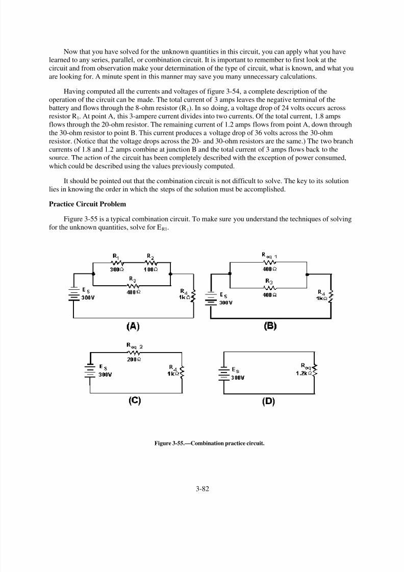
8/6/2019 NEETS MODULE 01 - Introduction to Matter, Energy, And Direct Current
http://slidepdf.com/reader/full/neets-module-01-introduction-to-matter-energy-and-direct-current 188/278
Now that you have solved for the unknown quantities in this circuit, you can apply what you havelearned to any series, parallel, or combination circuit. It is important to remember to first look at the
circuit and from observation make your determination of the type of circuit, what is known, and what you
are looking for. A minute spent in this manner may save you many unnecessary calculations.
Having computed all the currents and voltages of figure 3-54, a complete description of the
operation of the circuit can be made. The total current of 3 amps leaves the negative terminal of thebattery and flows through the 8-ohm resistor (R1). In so doing, a voltage drop of 24 volts occurs across
resistor R1. At point A, this 3-ampere current divides into two currents. Of the total current, 1.8 amps
flows through the 20-ohm resistor. The remaining current of 1.2 amps flows from point A, down through
the 30-ohm resistor to point B. This current produces a voltage drop of 36 volts across the 30-ohm
resistor. (Notice that the voltage drops across the 20- and 30-ohm resistors are the same.) The two branch
currents of 1.8 and 1.2 amps combine at junction B and the total current of 3 amps flows back to the
source. The action of the circuit has been completely described with the exception of power consumed,
which could be described using the values previously computed.
It should be pointed out that the combination circuit is not difficult to solve. The key to its solution
lies in knowing the order in which the steps of the solution must be accomplished.
Practice Circuit Problem
Figure 3-55 is a typical combination circuit. To make sure you understand the techniques of solving
for the unknown quantities, solve for ER1.
Figure 3-55.—Combination practice circuit.
3-82

8/6/2019 NEETS MODULE 01 - Introduction to Matter, Energy, And Direct Current
http://slidepdf.com/reader/full/neets-module-01-introduction-to-matter-energy-and-direct-current 189/278

8/6/2019 NEETS MODULE 01 - Introduction to Matter, Energy, And Direct Current
http://slidepdf.com/reader/full/neets-module-01-introduction-to-matter-energy-and-direct-current 190/278
Redraw the circuit as shown in figure 3-55(C).
Given:
Solution:
2. The total current (IT) is now computed.
Given:
Solution:
3. Solve for the voltage dropped across Req2. This represents the voltage dropped across the network
R1, R2, and R3 in the original circuit.
Given:
Solution:
4. Solve for the current through Req1. (Req1 represents the network R1 and R2 in the original circuit.)
Since the voltage across each branch of a parallel circuit is equal to the voltage across the
equivalent resistor representing the circuit:
3-84

8/6/2019 NEETS MODULE 01 - Introduction to Matter, Energy, And Direct Current
http://slidepdf.com/reader/full/neets-module-01-introduction-to-matter-energy-and-direct-current 191/278
Given:
Solution:
5. Solve for the voltage dropped across R1 (the quantity you were asked to find). Since Req1 represents the series network of R1 and R2 and total current flows through each resistor in a series
circuit, IR1 must equal IReq1.
Given:
Solution:
Q42. Refer to figure 3-55(A). If the following resistors were replaced with the values indicated: R 1 =
900Ω , R3 = lk Ω , what is the total power in the circuit? What is E R2?
REDRAWING CIRCUITS FOR CLARITY
You will notice that the schematic diagrams you have been working with have shown parallel
circuits drawn as neat square figures, with each branch easily identified.
In actual practice the wired circuits and more complex schematics are rarely laid out in this simpleform. For this reason, it is important for you to recognize that circuits can be drawn in a variety of ways,
and to learn some of the techniques for redrawing them into their simplified form. When a circuit is
redrawn for clarity or to its simplest form, the following steps are used.
1.
2.
3.
Trace the current paths in the circuit.
Label the junctions in the circuit.
Recognize points which are at the same potential.
3-85

8/6/2019 NEETS MODULE 01 - Introduction to Matter, Energy, And Direct Current
http://slidepdf.com/reader/full/neets-module-01-introduction-to-matter-energy-and-direct-current 192/278
4.
5.
Visualize a rearrangement, "stretching" or "shrinking," of connecting wires.
Redraw the circuit into simpler form (through stages if necessary).
To redraw any circuit, start at the source, and trace the path of current flow through the circuit. At
points where the current divides, called JUNCTIONS, parallel branches begin. These junctions are key
points of reference in any circuit and should be labeled as you find them. The wires in circuit schematicsare assumed to have NO RESISTANCE and there is NO VOLTAGE drop along any wire. This means
that any unbroken wire is at the same voltage all along its length, until it is interrupted by a resistor,
battery, or some other circuit component. In redrawing a circuit, a wire can be "stretched" or "shrunk" as
much as you like without changing any electrical characteristic of the circuit.
Figure 3-56(A) is a schematic of a circuit that is not drawn in the box-like fashion used in previous
illustrations. To redraw this circuit, start at the voltage source and trace the path for current to the junction
marked (a). At this junction the current divides into three paths. If you were to stretch the wire to show
the three current paths, the circuit would appear as shown in figure 3-56(B).
Figure 3-56.—Redrawing a simple parallel circuit.
While these circuits may appear to be different, the two drawings actually represent the same circuit.
The drawing in figure 3-56(B) is the familiar box-like structure and may be easier to work with. Figure
3-57(A) is a schematic of a circuit shown in a box-like structure, but may be misleading. This circuit in
reality is a series-parallel circuit that may be redrawn as shown in figure 3-57(B). The drawing in part (B)
of the figure is a simpler representation of the original circuit and could be reduced to just two resistors in
parallel.
3-86

8/6/2019 NEETS MODULE 01 - Introduction to Matter, Energy, And Direct Current
http://slidepdf.com/reader/full/neets-module-01-introduction-to-matter-energy-and-direct-current 193/278
Figure 3-57.—Redrawing a simple series-parallel circuit.
Redrawing a Complex Circuit
Figure 3-58(A) shows a complex circuit that may be redrawn for clarification in the following steps.
3-87

8/6/2019 NEETS MODULE 01 - Introduction to Matter, Energy, And Direct Current
http://slidepdf.com/reader/full/neets-module-01-introduction-to-matter-energy-and-direct-current 194/278
Figure 3-58.—Redrawing a complex circuit.
NOTE: As you redraw the circuit, draw it in simple box-like form. Each time you reach a junction, a
new branch is created by stretching or shrinking the wires.
Start at the negative terminal of the voltage source. Current flows through R1 to a junction and
divides into three paths; label this junction (a). Follow one of the paths of current through R 2 and R3 to a
junction where the current divides into two more paths. This junction is labeled (b).
The current through one branch of this junction goes through R 5 and back to the source. (The most
direct path.) Now that you have completed a path for current to the source, return to the last junction, (b).Follow current through the other branch from this junction. Current flows from junction (b) through R4 to
the source. All the paths from junction (b) have been traced. Only one path from junction (a) has been
completed. You must now return to junction (a) to complete the other two paths. From junction (a) the
current flows through R7 back to the source. (There are no additional branches on this path.) Return to
junction (a) to trace the third path from this junction. Current flows through R 6 and R8 and comes to a
junction. Label this junction (c). From junction (c) one path for current is through R 9 to the source. The
other path for current from junction (c) is through R10 to the source. All the junctions in this circuit have
3-88

8/6/2019 NEETS MODULE 01 - Introduction to Matter, Energy, And Direct Current
http://slidepdf.com/reader/full/neets-module-01-introduction-to-matter-energy-and-direct-current 195/278
now been labeled. The circuit and the junction can be redrawn as shown in figure 3-58(C). It is much
easier to recognize the series and parallel paths in the redrawn circuit.
Q43. What is the total resistance of the circuit shown in figure 3-59? (Hint: Redraw the circuit to
simplify and then use equivalent resistances to compute for RT .)
Figure 3-59.—Simplification circuit problem.
Q44. What is the total resistance of the circuit shown in figure 3-60?
Figure 3-60.—Source resistance in a parallel circuit.
Q45. What effect does the internal resistance have on the rest of the circuit shown in figure 3-60?
EFFECTS OF OPEN AND SHORT CIRCUITS
Earlier in this chapter the terms open and short circuits were discussed. The following discussion
deals with the effects on a circuit when an open or a short occurs.
3-89

8/6/2019 NEETS MODULE 01 - Introduction to Matter, Energy, And Direct Current
http://slidepdf.com/reader/full/neets-module-01-introduction-to-matter-energy-and-direct-current 196/278
The major difference between an open in a parallel circuit and an open in a series circuit is that in theparallel circuit the open would not necessarily disable the circuit. If the open condition occurs in a series
portion of the circuit, there will be no current because there is no complete path for current flow. If, on the
other hand, the open occurs in a parallel path, some current will still flow in the circuit. The parallel
branch where the open occurs will be effectively disabled, total resistance of the circuit will INCREASE,
and total current will DECREASE.
To clarify these points, figure 3-61 illustrates a series parallel circuit. First the effect of an open in
the series portion of this circuit will be examined. Figure 3-61(A) shows the normal circuit, RT = 40 ohms
and IT = 3 amps. In figure 3-61(B) an open is shown in the series portion of the circuit, there is no
complete path for current and the resistance of the circuit is considered to be infinite.
Figure 3-61.—Series-parallel circuit with opens.
In figure 3-61(C) an open is shown in the parallel branch of R3. There is no path for current throughR3. In the circuit, current flows through R 1 and R2 only. Since there is only one path for current flow, R1
and R2 are effectively in series.
Under these conditions RT = 120Ω and IT = 1 amp. As you can see, when an open occurs in a parallel
branch, total circuit resistance increases and total circuit current decreases.
A short circuit in a parallel network has an effect similar to a short in a series circuit. In general, the
short will cause an increase in current and the possibility of component damage regardless of the type of
3-90

8/6/2019 NEETS MODULE 01 - Introduction to Matter, Energy, And Direct Current
http://slidepdf.com/reader/full/neets-module-01-introduction-to-matter-energy-and-direct-current 197/278
circuit involved. To illustrate this point, figure 3-62 shows a series-parallel network in which shorts are
developed. In figure 3-62 (A) the normal circuit is shown. RT = 40 ohms and IT = 3 amps.
Figure 3-62.—Series-parallel circuit with shorts.
In figure 3-62 (B), R1 has shorted. R1 now has zero ohms of resistance. The total of the resistance of
the circuit is now equal to the resistance of the parallel network of R2 and R3, or 20 ohms. Circuit current
has increased to 6 amps. All of this current goes through the parallel network (R2, R3) and this increase in
current would most likely damage the components.
In figure 3-62 (C), R3 has shorted. With R3 shorted there is a short circuit in parallel with R2. The
short circuit routes the current around R2, effectively removing R2 from the circuit. Total circuit resistance
is now equal to the resistance of R1, or 20 ohms.
As you know, R2 and R3 form a parallel network. Resistance of the network can be calculated as
follows:
Given:
3-91
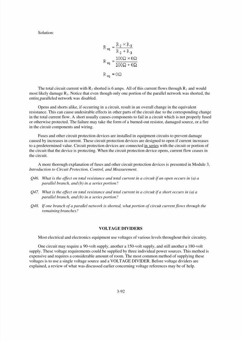
8/6/2019 NEETS MODULE 01 - Introduction to Matter, Energy, And Direct Current
http://slidepdf.com/reader/full/neets-module-01-introduction-to-matter-energy-and-direct-current 198/278
Solution:
The total circuit current with R3 shorted is 6 amps. All of this current flows through R1 and would
most likely damage R1. Notice that even though only one portion of the parallel network was shorted, the
entire paralleled network was disabled.
Opens and shorts alike, if occurring in a circuit, result in an overall change in the equivalent
resistance. This can cause undesirable effects in other parts of the circuit due to the corresponding change
in the total current flow. A short usually causes components to fail in a circuit which is not properly fused
or otherwise protected. The failure may take the form of a burned-out resistor, damaged source, or a fire
in the circuit components and wiring.
Fuses and other circuit protection devices are installed in equipment circuits to prevent damage
caused by increases in current. These circuit protection devices are designed to open if current increases
to a predetermined value. Circuit protection devices are connected in series with the circuit or portion of
the circuit that the device is protecting. When the circuit protection device opens, current flow ceases in
the circuit.
A more thorough explanation of fuses and other circuit protection devices is presented in Module 3,
Introduction to Circuit Protection, Control, and Measurement .
Q46. What is the effect on total resistance and total current in a circuit if an open occurs in (a) a parallel branch, and (b) in a series portion?
Q47. What is the effect on total resistance and total current in a circuit if a short occurs in (a) a
parallel branch, and (b) in a series portion?
Q48. If one branch of a parallel network is shorted, what portion of circuit current flows through the
remaining branches?
VOLTAGE DIVIDERS
Most electrical and electronics equipment use voltages of various levels throughout their circuitry.
One circuit may require a 90-volt supply, another a 150-volt supply, and still another a 180-volt
supply. These voltage requirements could be supplied by three individual power sources. This method is
expensive and requires a considerable amount of room. The most common method of supplying these
voltages is to use a single voltage source and a VOLTAGE DIVIDER. Before voltage dividers are
explained, a review of what was discussed earlier concerning voltage references may be of help.
3-92

8/6/2019 NEETS MODULE 01 - Introduction to Matter, Energy, And Direct Current
http://slidepdf.com/reader/full/neets-module-01-introduction-to-matter-energy-and-direct-current 199/278
As you know, some circuits are designed to supply both positive and negative voltages. Perhaps nowyou wonder if a negative voltage has any less potential than a positive voltage. The answer is that 100
volts is 100 volts. Whether it is negative or positive does not affect the feeling you get when you are
shocked.
Voltage polarities are considered as being positive or negative in respect to a reference point, usually
ground. Figure 3-63 will help to illustrate this point.
Figure 3-63.—Voltage polarities.
Figure 3-63(A) shows a series circuit with a voltage source of 100 volts and four 50-ohm resistors
connected in series. The ground, or reference point, is connected to one end of resistor R1. The current inthis circuit determined by Ohm
,s law is .5 amp. Each resistor develops (drops) 25 volts. The five tap-off
points indicated in the schematic are points at which the voltage can be measured. As indicated on the
schematic, the voltage measured at each of the points from point A to point E starts at zero volts and
becomes more positive in 25 volt steps to a value of positive 100 volts.
In figure 3-63(B), the ground, or reference point has been moved to point B. The current in the
circuit is still .5 amp and each resistor still develops 25 volts. The total voltage developed in the circuitremains at 100 volts, but because the reference point has been changed, the voltage at point A is negative
25 volts. Point E, which was at positive 100 volts in figure 3-63(A), now has a voltage of positive 75
volts. As you can see the voltage at any point in the circuit is dependent on three factors; the current
through the resistor, the ohmic value of the resistor, and the reference point in the circuit.
A typical voltage divider consists of two or more resistors connected in series across a source
voltage (Es). The source voltage must be as high or higher than any voltage developed by the voltage
divider. As the source voltage is dropped in successive steps through the series resistors, any desired
3-93

8/6/2019 NEETS MODULE 01 - Introduction to Matter, Energy, And Direct Current
http://slidepdf.com/reader/full/neets-module-01-introduction-to-matter-energy-and-direct-current 200/278
portion of the source voltage may be "tapped off" to supply individual voltage requirements. The values
of the series resistors used in the voltage divider are determined by the voltage and current requirements
of the loads.
Figure 3-64 is used to illustrate the development of a simple voltage divider. The requirement for
this voltage divider is to provide a voltage of 25 volts and a current of 910 milliamps to the load from a
source voltage of 100 volts. Figure 3-64(A) provides a circuit in which 25 volts is available at point B. Ifthe load was connected between point B and ground, you might think that the load would be supplied
with 25 volts. This is not true since the load connected between point B and ground forms a parallel
network of the load and resistor R1. (Remember that the value of resistance of a parallel network is
always less than the value of the smallest resistor in the network.)
Figure 3-64.—Simple voltage divider.
Since the resistance of the network would now be less than 25 ohms, the voltage at point B would be
less than 25 volts. This would not satisfy the requirement of the load.
To determine the size of resistor used in the voltage divider, a rule-of-thumb is used. The current in
the divider resistor should equal approximately 10 percent of the load current. This current, which doesnot flow through any of the load devices, is called bleeder current.
Given this information, the voltage divider can be designed using the following steps.
1. Determine the load requirement and the available voltage source.
3-94

8/6/2019 NEETS MODULE 01 - Introduction to Matter, Energy, And Direct Current
http://slidepdf.com/reader/full/neets-module-01-introduction-to-matter-energy-and-direct-current 201/278
2. Select bleeder current by applying the 10% rule-of-thumb.
3. Calculate bleeder resistance.
The value of R1 may be rounded off to 275 ohms:
4. Calculate the total current (load plus bleeder).
5. Calculate the resistance of the other divider resistor(s).
The voltage divider circuit can now be drawn as shown in figure 3-64(B).
Q49. What information must be known to determine the component values for a voltage divider?
3-95

8/6/2019 NEETS MODULE 01 - Introduction to Matter, Energy, And Direct Current
http://slidepdf.com/reader/full/neets-module-01-introduction-to-matter-energy-and-direct-current 202/278
Q50. If a voltage divider is required for a load that will use 450 mA of current, what should be the value
of bleeder current?
Q51. If the load in question 50 requires a voltage of +90 V, what should be the value of the bleeder
resistor?
Q52. If the source voltage for the voltage divider in question 50 supplies 150 volts, what is the totalcurrent through the voltage divider?
MULTIPLE-LOAD VOLTAGE DIVIDERS
A multiple-load voltage divider is shown in figure 3-65. An important point that was not emphasized
before is that when using the 10% rule-of-thumb to calculate the bleeder current, you must take 10% of
the total load current.
Figure 3-65.—Multiple-load voltage divider.
Given the information shown in figure 3-65, you can calculate the values for the resistors needed in
the voltage-divider circuits. The same steps will be followed as in the previous voltage divider problem.
3-96
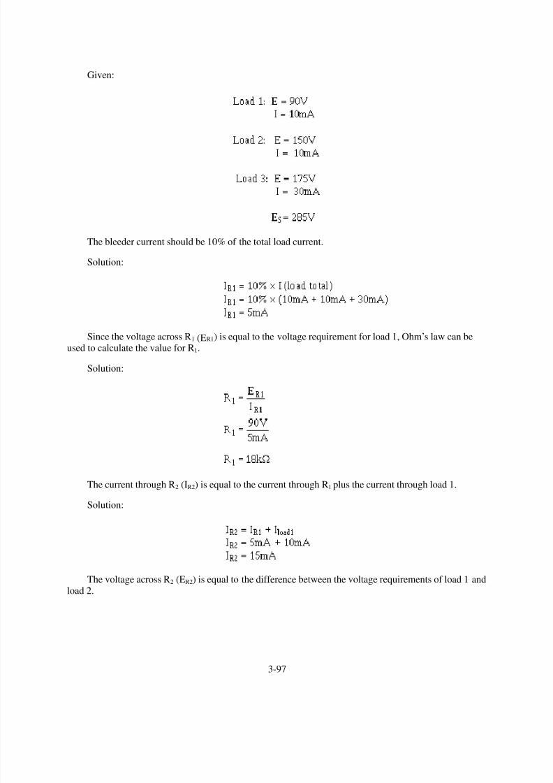
8/6/2019 NEETS MODULE 01 - Introduction to Matter, Energy, And Direct Current
http://slidepdf.com/reader/full/neets-module-01-introduction-to-matter-energy-and-direct-current 203/278
Given:
The bleeder current should be 10% of the total load current.
Solution:
Since the voltage across R1 (ER1) is equal to the voltage requirement for load 1, Ohm,s law can be
used to calculate the value for R1.
Solution:
The current through R2 (IR2) is equal to the current through R1 plus the current through load 1.
Solution:
The voltage across R2 (ER2) is equal to the difference between the voltage requirements of load 1 and
load 2.
3-97
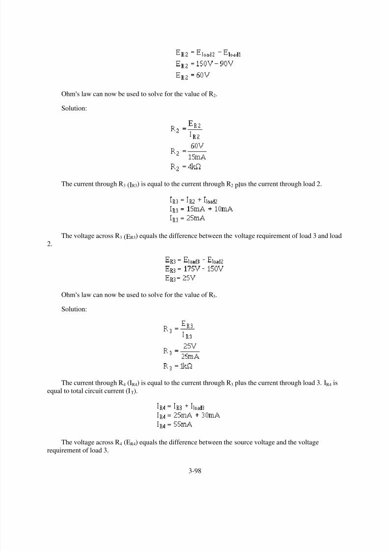
8/6/2019 NEETS MODULE 01 - Introduction to Matter, Energy, And Direct Current
http://slidepdf.com/reader/full/neets-module-01-introduction-to-matter-energy-and-direct-current 204/278
Ohm
,
s law can now be used to solve for the value of R2.
Solution:
The current through R3 (IR3) is equal to the current through R2 plus the current through load 2.
The voltage across R3 (ER3) equals the difference between the voltage requirement of load 3 and load
2.
Ohm,s law can now be used to solve for the value of R3.
Solution:
The current through R4 (IR4) is equal to the current through R3 plus the current through load 3. IR4 isequal to total circuit current (IT).
The voltage across R4 (ER4) equals the difference between the source voltage and the voltage
requirement of load 3.
3-98
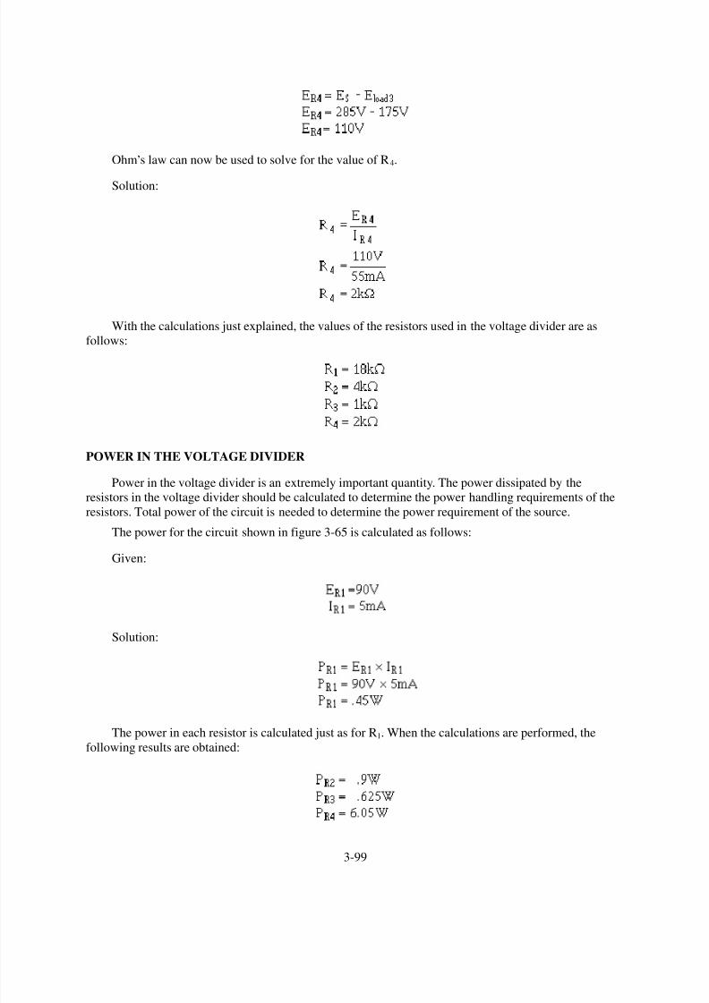
8/6/2019 NEETS MODULE 01 - Introduction to Matter, Energy, And Direct Current
http://slidepdf.com/reader/full/neets-module-01-introduction-to-matter-energy-and-direct-current 205/278

8/6/2019 NEETS MODULE 01 - Introduction to Matter, Energy, And Direct Current
http://slidepdf.com/reader/full/neets-module-01-introduction-to-matter-energy-and-direct-current 206/278
To calculate the power for load 1:
Given:
Solution:
The power in each load is calculated just as for load 1. When the calculations are performed, the
following results are obtained.
Total power is calculated by summing the power consumed by the loads and the power dissipated by
the divider resistors. The total power in the circuit is 15.675 watts.
The power used by the loads and divider resistors is supplied by the source. This applies to all
electrical circuits; power for all components is supplied by the source.
Since power is the product of voltage and current, the power supplied by the source is equal to the
source voltage multiplied by the total circuit current (Es x IT).
In the circuit of figure 3-65, the total power can be calculated by:
Given:
Solution:
VOLTAGE DIVIDER WITH POSITIVE AND NEGATIVE VOLTAGE REQUIREMENTS
In many cases the load for a voltage divider requires both positive and negative voltages. Positiveand negative voltages can be supplied from a single source voltage by connecting the ground (reference
point) between two of the divider resistors. The exact point in the circuit at which the reference point is
placed depends upon the voltages required by the loads.
3-100

8/6/2019 NEETS MODULE 01 - Introduction to Matter, Energy, And Direct Current
http://slidepdf.com/reader/full/neets-module-01-introduction-to-matter-energy-and-direct-current 207/278
For example, a voltage divider can be designed to provide the voltage and current to three loads from
a given source voltage.
Given:
The circuit is drawn as shown in figure 3-66. Notice the placement of the ground reference point.
The values for resistors R1, R3, and R4 are computed exactly as was done in the last example. IR1 is thebleeder current and can be calculated as follows:
Figure 3-66.—Voltage divider providing both positive and negative voltages.
Solution:
Calculate the value of R1.
3-101

8/6/2019 NEETS MODULE 01 - Introduction to Matter, Energy, And Direct Current
http://slidepdf.com/reader/full/neets-module-01-introduction-to-matter-energy-and-direct-current 208/278
Solution:
Calculate the current through R2 using Kirchhoff ,s current law.
At point A:
(or 195mA leaving point A)
Since ER2 = E load 2, you can calculate the value of R2.
Solution:
Calculate the current through R3.
The voltage across R3 (ER3) equals the difference between the voltage requirements of loads 3 and 2.
Solution:
Calculate the value of R3.
3-102
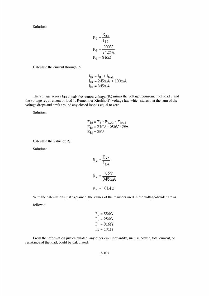
8/6/2019 NEETS MODULE 01 - Introduction to Matter, Energy, And Direct Current
http://slidepdf.com/reader/full/neets-module-01-introduction-to-matter-energy-and-direct-current 209/278
Solution:
Calculate the current through R4.
The voltage across ER4 equals the source voltage (Es) minus the voltage requirement of load 3 and
the voltage requirement of load 1. Remember Kirchhoff ,s voltage law which states that the sum of the
voltage drops and emfs around any closed loop is equal to zero.
Solution:
Calculate the value of R4.
Solution:
With the calculations just explained, the values of the resistors used in the voltage/divider are as
follows:
From the information just calculated, any other circuit quantity, such as power, total current, or
resistance of the load, could be calculated.
3-103

8/6/2019 NEETS MODULE 01 - Introduction to Matter, Energy, And Direct Current
http://slidepdf.com/reader/full/neets-module-01-introduction-to-matter-energy-and-direct-current 210/278
PRACTICAL APPLICATION OF VOLTAGE DIVIDERS
In actual practice the computed value of the bleeder resistor does not always come out to an even
value. Since the rule-of-thumb for bleeder current is only an estimated value, the bleeder resistor can be
of a value close to the computed value. (If the computed value of the resistance were 510 ohms, a 500-
ohm resistor could be used.) Once the actual value of the bleeder resistor is selected, the bleeder current
must be recomputed. The voltage developed by the bleeder resistor must be equal to the voltagerequirement of the load in parallel with the bleeder resistor.
The value of the remaining resistors in the voltage divider is computed from the current through the
remaining resistors and the voltage across them. These values must be used to provide the required
voltage and current to the loads.
If the computed values for the divider resistors are not even values; series, parallel, or series-parallel
networks can be used to provide the required resistance.
Example: A voltage divider is required to supply two loads from a 190.5 volts source. Load 1
requires +45 volts and 210 milliamps; load 2 requires +165 volts and 100 milliamps.
Calculate the bleeder current using the rule-of-thumb.
Given:
Solution:
Calculate the ohmic value of the bleeder resistor.
Given:
Solution:
Since it would be difficult to find a resistor of 1451.6 ohms, a practical choice for R1 is 1500 ohms.
Calculate the actual bleeder current using the selected value for R1.
3-104
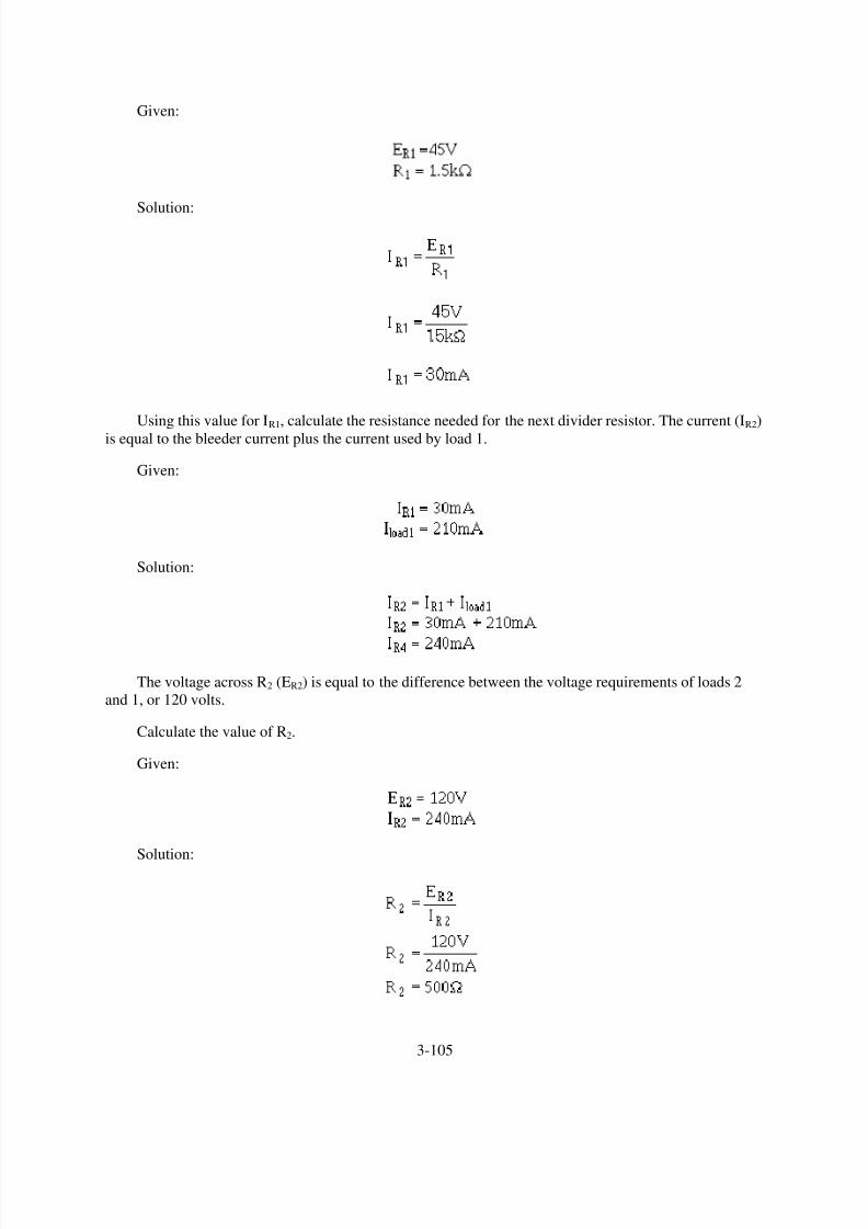
8/6/2019 NEETS MODULE 01 - Introduction to Matter, Energy, And Direct Current
http://slidepdf.com/reader/full/neets-module-01-introduction-to-matter-energy-and-direct-current 211/278
Given:
Solution:
Using this value for IR1, calculate the resistance needed for the next divider resistor. The current (IR2)
is equal to the bleeder current plus the current used by load 1.
Given:
Solution:
The voltage across R2 (ER2) is equal to the difference between the voltage requirements of loads 2
and 1, or 120 volts.
Calculate the value of R2.
Given:
Solution:
3-105

8/6/2019 NEETS MODULE 01 - Introduction to Matter, Energy, And Direct Current
http://slidepdf.com/reader/full/neets-module-01-introduction-to-matter-energy-and-direct-current 212/278

8/6/2019 NEETS MODULE 01 - Introduction to Matter, Energy, And Direct Current
http://slidepdf.com/reader/full/neets-module-01-introduction-to-matter-energy-and-direct-current 213/278
Figure 3-67.—Practical example of a voltage divider.
Q53. In figure 3-67, why is the value of R1 calculated first?
Q54. In figure 3-67, how is (a) the current through R2 and (b) the voltage drop across R2 computed?
Q55. In figure 3-67, what is the power dissipated in R1?
Q56. In figure 3-67, what is the purpose of the series-parallel network R3 , R 4 , and R5?
Q57. In figure 3-67, what should be the minimum wattage ratings of R3 and R5?
Q58. If the load requirement consists of both positive and negative voltages, what technique is used in
the voltage divider to supply the loads from a single voltage source?
EQUIVALENT CIRCUIT TECHNIQUES
The circuit solutions that you have studied up to this point have been obtained mainly through the
use of formulas derived from Ohm,s law. As in many other fields of science, electricity has its share of
special shortcut methods. Some of the special circuit analysis techniques are: THEVENIN,S THEOREM,
which uses a process of circuit reduction to Thevenin,s equivalent circuit; and NORTON
,S THEOREM,
which is reduction of a circuit to Norton,s equivalent. Another method is called LOOP ANALYSIS. This
uses Kirchhoff ,s voltage law to simultaneously solve problems in parallel branches of a circuit. The use of
3-107

8/6/2019 NEETS MODULE 01 - Introduction to Matter, Energy, And Direct Current
http://slidepdf.com/reader/full/neets-module-01-introduction-to-matter-energy-and-direct-current 214/278
these methods should be reserved until you have become thoroughly familiar with the methods covered
thus far in this chapter. You may want to explore some of the special techniques later in your career.
ELECTRICAL SAFETY
Safety precautions must always be observed by persons working around electric circuits and
equipment to avoid injury from electric shock. Detailed safety precautions are contained in NAVMAT
P-5l00, Safety Precautions for Shore Activities and OPNAVINST 5l00-19, Navy Safety Precautions for
Forces Afloat .
The danger of shock from a 450-volt ac electrical service system is well recognized by operating
personnel. This is shown by the relatively low number of reports of serious shock received from this
voltage, despite its widespread use. On the other hand, a number of fatalities have been reported due to
contact with low-voltage circuits. Despite a fairly widespread, but totally unfounded, popular belief to the
contrary, low-voltage circuits (115 volts and below) are very dangerous and can cause death when the
resistance of the body is lowered. Fundamentally, current, rather than voltage, is the measure of shock
intensity. The passage of even a very small current through a vital part of the human body can cause
DEATH. The voltage necessary to produce the fatal current is dependent upon the resistance of the body,contact conditions, the path through the body, etc. For example, when a 60-hertz alternating current, is
passed through a human body from hand to hand or from hand to foot, and the current is gradually
increased, it will cause the following effects: At about 1 milliampere (0.001 ampere), the shock can be
felt; at about 10 milliamperes (0.01 ampere), the shock is of sufficient intensity to prevent voluntary
control of the muscles; and at about 100 milliamperes (0.1 ampere) the shock is fatal if it lasts for 1
second or more. The above figures are the results of numerous investigations and are approximate
because individuals differ in their resistance to electrical shock. It is most important to recognize that the
resistance of the human body cannot be relied upon to prevent a fatal shock from 115 volts or less—
FATALITIES FROM VOLTAGES AS LOW AS 30 VOLTS HAVE BEEN RECORDED. Tests have
shown that body resistance under unfavorable conditions may be as low as 300 ohms, and possibly as low
as 100 ohms from temple to temple if the skin is broken.
Conditions aboard ship add to the chance of receiving an electrical shock. Aboard ship the body islikely to be in contact with the metal structure of the ship and the body resistance may be low because of
perspiration or damp clothing. Extra care and awareness of electrical hazards aboard ship are needed.
Short circuits can be caused by accidentally placing or dropping a metal tool, rule, flashlight case, or
other conducting article across an energized line. The arc and fire which result, even on relatively low-
voltage circuits, may cause extensive damage to equipment and serious injury to personnel.
Since ship service power distribution systems are designed to be ungrounded, many persons believe
it is safe to touch one conductor, since no electrical current would flow. This is not true, since the
distribution system is not totally isolated from the hull of the ship. If one conductor of an ungrounded
electrical system is touched while the body is in contact with the hull of the ship or other metal equipment
enclosure, a fatal electric current may pass through the body. ALL LIVE ELECTRIC CIRCUITS SHALL
BE TREATED AS POTENTIAL HAZARDS AT ALL TIMES.
DANGER SIGNALS
Personnel should constantly be on the alert for any signs which might indicate a malfunction of
electric equipment. Besides the more obvious visual signs, the reaction of other senses, such as hearing,
smell, and touch, should also make you aware of possible electrical malfunctions. Examples of signs
which you must be alert for are: fire, smoke, sparks, arcing, or an unusual sound from an electric motor.
3-108

8/6/2019 NEETS MODULE 01 - Introduction to Matter, Energy, And Direct Current
http://slidepdf.com/reader/full/neets-module-01-introduction-to-matter-energy-and-direct-current 215/278
Frayed and damaged cords or plugs; receptacles, plugs, and cords which feel warm to the touch; slight
shocks felt when handling electrical equipment; unusually hot running electric motors and other electrical
equipment; an odor of burning or overheated insulation; electrical equipment which either fails to operate
or operates irregularly; and electrical equipment which produces excessive vibrations are also indications
of malfunctions. When any of the above signs are noted, they are to be reported immediately to a
qualified technician. DO NOT DELAY. Do not operate faulty equipment. Above all, do not attempt to
make any repairs yourself if you are not qualified to do so. Stand clear of any suspected hazard andinstruct others to do likewise.
•
•
•
•
Warning Signs—They have been placed for your protection. To disregard them is to invite
personal injury as well as possible damage to equipment. Switches and receptacles with a
temporary warning tag, indicating work is being performed, are not to be touched.
Working Near Electrical Equipment—When work must be performed in the immediate vicinity
of electrical equipment, check with the technician responsible for the maintenance of the
equipment so you can avoid any potential hazards of which you may not be immediately aware.
Authorized Personnel Only—Because of the danger of fire, damage to equipment, and injury to
personnel, all repair and maintenance work on electrical equipment shall be done only by
authorized persons. Keep your hands off of all equipment which you have not been specifically
authorized to handle. Particularly stay clear of electrical equipment opened for inspection,
testing, or servicing.
Circuit Breakers and Fuses—Covers for all fuse boxes, junction boxes, switch boxes, and wiring
accessories should be kept closed. Any cover which is not closed or is missing should be
reported to the technician responsible for its maintenance. Failure to do so may result in injury to
personnel or damage to equipment in the event accidental contact is made with exposed live
circuits.
ELECTRICAL FIRES
Carbon dioxide (CO2) is used in fighting electrical fires. It is nonconductive and, therefore, the safest
to use in terms of electrical safety. It also offers the least likelihood of damaging equipment. However, if
the discharge horn of a CO2 extinguisher is allowed to accidentally touch an energized circuit, the horn
may transmit a shock to the person handling the extinguisher.
The very qualities which cause CO2 to be a valuable extinguishing agent also make it dangerous to
life. When it replaces oxygen in the air to the extent that combustion cannot be sustained, respiration also
cannot be sustained. Exposure of a person to an atmosphere of high concentration of CO2 will cause
suffocation.
FIRST AID FOR ELECTRIC SHOCK
A person who has stopped breathing is not necessarily dead, but is in immediate danger. Life is
dependent upon oxygen, which is breathed into the lungs and then carried by the blood to every body cell.
Since body cells cannot store oxygen, and since the blood can hold only a limited amount (and that only
for a short time), death will surely result from continued lack of breathing.
However, the heart may continue to beat for some time after breathing has stopped, and the blood
may still be circulated to the body cells. Since the blood will, for a short time, contain a small supply of
3-109

8/6/2019 NEETS MODULE 01 - Introduction to Matter, Energy, And Direct Current
http://slidepdf.com/reader/full/neets-module-01-introduction-to-matter-energy-and-direct-current 216/278
oxygen, the body cells will not die immediately. For a very few minutes, there is some chance that the
person,s life may be saved.
The process by which a person who has stopped breathing can be saved is called ARTIFICIAL
VENTILATION (RESPIRATION).
The purpose of artificial ventilation is to force air out of the lungs and into the lungs, in rhythmicalternation, until natural breathing is reestablished. Artificial ventilation should be given only when
natural breathing has stopped; it should NOT be given to any person who is breathing naturally. You
should not assume that an individual who is unconscious due to electrical shock has stopped breathing. To
tell if someone suffering from an electrical shock is breathing, place your hands on the person,s sides, at
the level of the lowest ribs. If the victim is breathing, you will usually be able to feel the movement.Remember: DO NOT GIVE ARTIFICIAL VENTILATION TO A PERSON WHO IS BREATHING
NATURALLY.
Records show that seven out of ten victims of electric shock were revived when artificial respiration
was started in less than 3 minutes. After 3 minutes, the chances of revival decrease rapidly.
Once it has been determined that breathing has stopped, the person nearest the victim should start the
artificial ventilation without delay and send others for assistance and medical aid. The only logical,permissible delay is that required to free the victim from contact with the electricity in the quickest, safest
way. This step, while it must be taken quickly, must be done with great care; otherwise, there may be two
victims instead of one. In the case of portable electric tools, lights, appliances, equipment, or portable
outlet extensions, this should be done by turning off the supply switch or by removing the plug from its
receptacle. If the switch or receptacle cannot be quickly located, the suspected electrical device may be
pulled free of the victim. Other persons arriving on the scene must be clearly warned not to touch the
suspected equipment until it is deenergized. Aid should be enlisted to unplug the device as soon as
possible. The injured person should be pulled free of contact with stationary equipment (such as a bus
bar) if the equipment cannot be quickly deenergized, or if considerations of military operation or unit
survival prevent immediate shutdown of the circuits.
This can be done quickly and safely by carefully applying the following procedures:
1.
2.
Protect yourself with dry insulating material.
Use a dry board, belt, clothing, or other available nonconductive material to free the victim from
electrical contact. DO NOT TOUCH THE VICTIM UNTIL THE SOURCE OF ELECTRICITY
HAS BEEN REMOVED.
Once the victim has been removed from the electrical source, it should be determined, if the person
is breathing. If the person is not breathing, a method of artificial ventilation is used.
Sometimes victims of electrical shock suffer cardiac arrest (heart stoppage) as well as loss of
breathing. Artificial ventilation alone is not enough in cases where the heart has stopped. A technique
known as Cardiopulmonary Resuscitation (CPR) has been developed to provide aid to a person who hasstopped breathing and suffered a cardiac arrest. Because you most likely will be working in the field of
electricity, the risk of electrical shock is higher than most other Navy occupations. You should, at your
earliest opportunity, learn the technique of CPR.
CPR is relatively easy to learn and is taught in courses available from the American Red Cross, some
Navy Medical Departments, and in the Standard First Aid Training Course (NAVEDTRA 12081).
3-110

8/6/2019 NEETS MODULE 01 - Introduction to Matter, Energy, And Direct Current
http://slidepdf.com/reader/full/neets-module-01-introduction-to-matter-energy-and-direct-current 217/278
Q59. Is it considered safe for a person to touch any energized low-voltage conductor with the bare
hand?
Q60. What should you do if you become aware of a possible malfunction in a piece of electrical
equipment?
Q61. Who should perform CPR?
SUMMARY
With the completion of this chapter you have gained a basic understanding of dc circuits. The
information you have learned will provide you with a firm foundation for continuing your study of
electricity. The following is a summary of the important points in the chapter.
A BASIC ELECTRIC CIRCUIT consists of a source of electrical energy connected to a load. The
load uses the energy and changes it to a useful form.
A SCHEMATIC DIAGRAM is a "picture" of a circuit, which uses symbols to represent
components. The space required to depict an electrical or electronic circuit is greatly reduced by the use
of a schematic.
3-111

8/6/2019 NEETS MODULE 01 - Introduction to Matter, Energy, And Direct Current
http://slidepdf.com/reader/full/neets-module-01-introduction-to-matter-energy-and-direct-current 218/278
VOLTAGE (E) is the electrical force or pressure operating in a circuit.
AN AMPERE (A) represents the current flow produced by one volt working across one ohm of
resistance.
RESISTANCE (R) is the opposition to current. It is measured in ohms (Ω). One ohm of resistance
will limit the current produced by one volt to a level of one ampere.
THE OHM,S FORMULA can be transposed to find one of the values in a circuit if the other two
values are known. You can transpose the Ohm,s law formula
mathematically, or you can use the Ohm,s law figure to determine the mathematical relationship between
R, E, and I.
3-112
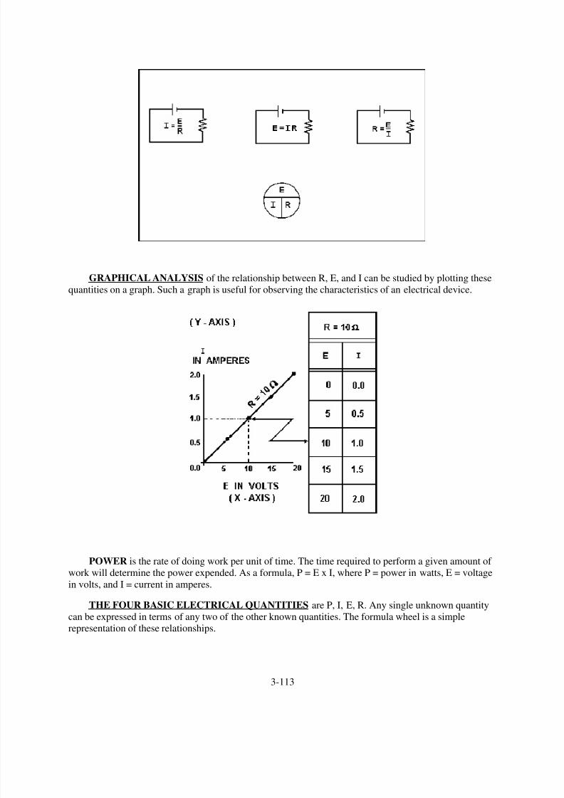
8/6/2019 NEETS MODULE 01 - Introduction to Matter, Energy, And Direct Current
http://slidepdf.com/reader/full/neets-module-01-introduction-to-matter-energy-and-direct-current 219/278
GRAPHICAL ANALYSIS of the relationship between R, E, and I can be studied by plotting thesequantities on a graph. Such a graph is useful for observing the characteristics of an electrical device.
POWER is the rate of doing work per unit of time. The time required to perform a given amount ofwork will determine the power expended. As a formula, P = E x I, where P = power in watts, E = voltage
in volts, and I = current in amperes.
THE FOUR BASIC ELECTRICAL QUANTITIES are P, I, E, R. Any single unknown quantity
can be expressed in terms of any two of the other known quantities. The formula wheel is a simple
representation of these relationships.
3-113
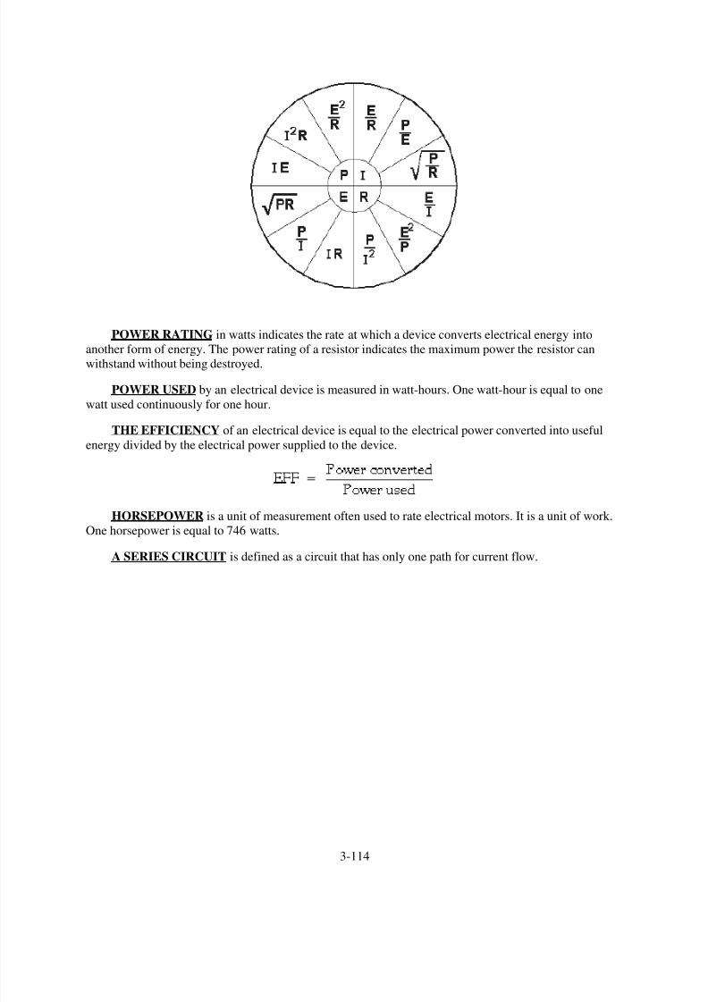
8/6/2019 NEETS MODULE 01 - Introduction to Matter, Energy, And Direct Current
http://slidepdf.com/reader/full/neets-module-01-introduction-to-matter-energy-and-direct-current 220/278
POWER RATING in watts indicates the rate at which a device converts electrical energy into
another form of energy. The power rating of a resistor indicates the maximum power the resistor canwithstand without being destroyed.
POWER USED by an electrical device is measured in watt-hours. One watt-hour is equal to one
watt used continuously for one hour.
THE EFFICIENCY of an electrical device is equal to the electrical power converted into useful
energy divided by the electrical power supplied to the device.
HORSEPOWER is a unit of measurement often used to rate electrical motors. It is a unit of work.
One horsepower is equal to 746 watts.
A SERIES CIRCUIT is defined as a circuit that has only one path for current flow.
3-114

8/6/2019 NEETS MODULE 01 - Introduction to Matter, Energy, And Direct Current
http://slidepdf.com/reader/full/neets-module-01-introduction-to-matter-energy-and-direct-current 221/278
RULES FOR SERIES DC CIRCUITS:
•
•
•
•
•
The same current flows through each part of a series circuit.
The total resistance of a series circuit is equal to the sum of the individual resistances.
The total voltage across a series circuit is equal to the sum of the individual voltage drops.
The voltage drop across a resistor in a series circuit is proportional to the ohmic value of the
resistor.
The total power in a series circuit is equal to the sum of the individual power used by each
circuit component.
KIRCHHOFF,S VOLTAGE LAW states: The algebraic sum of the voltage drops in any closed
path in a circuit and the electromotive forces in that path is equal to zero, or Ea + Eb + Ec +...En = 0.
3-115

8/6/2019 NEETS MODULE 01 - Introduction to Matter, Energy, And Direct Current
http://slidepdf.com/reader/full/neets-module-01-introduction-to-matter-energy-and-direct-current 222/278
VOLTAGE POLARITIES must be used when applying Kirchhoff ,s voltage law. The point at
which current enters a load (resistor) is considered negative with respect to the point at which current
leaves the load.
SERIES AIDING VOLTAGES cause current to flow in the same direction; thus the voltages are
added.
SERIES OPPOSING VOLTAGES tend to force current to flow in opposite directions; thus the
equivalent voltage is the difference between the opposing voltages.
A REFERENCE POINT is a chosen point in a circuit to which all other points are compared.
3-116

8/6/2019 NEETS MODULE 01 - Introduction to Matter, Energy, And Direct Current
http://slidepdf.com/reader/full/neets-module-01-introduction-to-matter-energy-and-direct-current 223/278
AN OPEN CIRCUIT is one in which a break exists in the complete conducting pathway.
A SHORT CIRCUIT is an accidental path of low resistance which passes an abnormally high
amount of current.
INTERNAL RESISTANCE causes a drop in the terminal voltage of a source as current flows
through the source. The decrease in terminal voltage is caused by the voltage drop across the internal
resistance. All sources of electromotive force have some form of internal resistance.
3-117

8/6/2019 NEETS MODULE 01 - Introduction to Matter, Energy, And Direct Current
http://slidepdf.com/reader/full/neets-module-01-introduction-to-matter-energy-and-direct-current 224/278
HIGH EFFICIENCY in a circuit is achieved when the resistance of the load is high with respect to
the resistance of the source.
3-118

8/6/2019 NEETS MODULE 01 - Introduction to Matter, Energy, And Direct Current
http://slidepdf.com/reader/full/neets-module-01-introduction-to-matter-energy-and-direct-current 225/278
POWER TRANSFER in a circuit is highest when the resistance of the load equals the resistance of
the source.
A PARALLEL CIRCUIT is a circuit having more than one current path connected to a common
voltage source.
RULES FOR PARALLEL DC CIRCUITS:
•
•
•
•
•
The same voltage exists across each branch of a parallel circuit and is equal to the source
voltage.
The current through a branch of a parallel network is inversely proportional to the amount of
resistance of the branch.
The total current of a parallel circuit is equal to the sum of the currents of the individual branches
of the circuit.
The total resistance of a parallel circuit is equal to the reciprocal of the sum of the reciprocals of
the individual resistances of the circuit.
The total power consumed in a parallel circuit is equal to the sum of the power consumptions of
the individual resistances.
THE SOLUTION OF A COMBINATION CIRCUIT is a matter of applying the laws and rules
for series and parallel circuits as applicable.
3-119

8/6/2019 NEETS MODULE 01 - Introduction to Matter, Energy, And Direct Current
http://slidepdf.com/reader/full/neets-module-01-introduction-to-matter-energy-and-direct-current 226/278
ALL PARALLEL CIRCUITS ARE COMBINATION CIRCUITS when the internal resistance
of the source is taken into account.
REDRAWING CIRCUITS FOR CLARITY is accomplished in the following steps:
1.
2.
3.
4.
5.
Trace the current paths in the circuit.
Label the junctions in the circuit.
Recognize points which are at the same potential.
Visualize rearrangements, "stretching" or "shrinking," of connecting wires.
Redraw the circuit into simpler form (through stages if necessary).
3-120

8/6/2019 NEETS MODULE 01 - Introduction to Matter, Energy, And Direct Current
http://slidepdf.com/reader/full/neets-module-01-introduction-to-matter-energy-and-direct-current 227/278
EQUIPMENT PROTECTION from short-circuit current is accomplished by use of fuses and other
circuit protection devices.
A VOLTAGE DIVIDER is a series circuit in which desired portions of the source voltage may be
tapped off for use in equipment. Both negative and positive voltage can be provided to the loads by the
proper selection of the reference point (ground).
3-121

8/6/2019 NEETS MODULE 01 - Introduction to Matter, Energy, And Direct Current
http://slidepdf.com/reader/full/neets-module-01-introduction-to-matter-energy-and-direct-current 228/278
ELECTRICAL SAFETY PRECAUTIONS must be observed. A fatal shock can occur from 0.1
ampere of current. Voltages as low as 30 volts have been recorded as causing sufficient current to be fatal.
ALL LIVE ELECTRICAL CIRCUITS shall be treated as potential hazards at all times.
ELECTRONIC OR ELECTRICAL EQUIPMENT discovered to be faulty or unsafe should be
reported immediately to proper authority.
ELECTRICAL OR ELECTRONIC EQUIPMENT should be used and repaired by authorized
personnel only.
A CO2 EXTINGUISHER should be used to extinguish electrical fires.
FIRST AID FOR ELECTRICAL SHOCK includes the following actions:
•
•
•
•
Remove the victim from the source of the shock.
Check the victim to see if the person is breathing.
If the victim is not breathing, give artificial ventilation. The preferred method is
mouth-to-mouth.
CPR may be necessary if the heartbeat has stopped, but do not attempt this unless you have been
trained in its use. OBTAIN MEDICAL ASSISTANCE AS SOON AS POSSIBLE.
3-122

8/6/2019 NEETS MODULE 01 - Introduction to Matter, Energy, And Direct Current
http://slidepdf.com/reader/full/neets-module-01-introduction-to-matter-energy-and-direct-current 229/278

8/6/2019 NEETS MODULE 01 - Introduction to Matter, Energy, And Direct Current
http://slidepdf.com/reader/full/neets-module-01-introduction-to-matter-energy-and-direct-current 230/278
A18.
A19.
A20. The source voltage would have to be increased to 640 volts.
A21.
A22. The point at which current enters the resistor is assigned a negative polarity and the point at
which current leaves the resistor is assigned a positive polarity.
A23. 2 amperes.
A24. 120 volts.
A25. 50 volts.
A26. Zero volts.
A27. A circuit where there is no longer a complete path for current flow.
A28. An accidental path of low resistance which passes an abnormally high amount of current.
A29. The internal (source) resistance of the battery will drop some of the voltage.
A30. When the load resistance equals the source resistance.
A31. 50 percent.
3-124

8/6/2019 NEETS MODULE 01 - Introduction to Matter, Energy, And Direct Current
http://slidepdf.com/reader/full/neets-module-01-introduction-to-matter-energy-and-direct-current 231/278
A32.
A33. 60 volts.
A34. Total current in a series circuit flows through every circuit component but in a parallel circuit total
current divides among the available paths.
A35. Whether the current is entering the junction (+) or leaving the junction (-).
A36.
A37.
A38.
A39. Equivalent resistor or Req.
A40. In both cases all the power used in the circuit must come from the source.
A41.
A42. PT = 60 W, E R2 = 10 V.
A43. 4Ω.
A44. 25Ω.
3-125
8/6/2019 NEETS MODULE 01 - Introduction to Matter, Energy, And Direct Current
http://slidepdf.com/reader/full/neets-module-01-introduction-to-matter-energy-and-direct-current 232/278
3-126
A45. Because of the 2-volt drop across the internal resistance, only 48 volts is available for the rest of
the circuit.
A46. (a) Total resistance increases, total current decreases (b) Total resistance becomes infinite, total
current is equal to zero
A47. (a) Total resistance decreases, total current increases (b) Total resistance decreases, total currentincreases
A48. None.
A49. The source voltage and load requirements (voltage and current).
A50. 45 mA rule-of-thumb.
A51. 2 k Ω.
A52. 495 mA.
A53. R1 is the bleeder resistor. Bleeder current must be known before any of the remaining divider
resistor ohmic values can be computed.
A54. (a) By adding the bleeder current (I R1) and the current through load 1(b) By subtracting the voltage
of load 1 from the voltage of load 2.
A55. 1.35 watts.
A56. The series-parallel network drops the remaining source voltage and is used to take the place of a
single resistor (75 ohms) when the required ohmic value is not available in a single resistor.
A57. R3 = 2 watts; R5 = 6 watts.
A58. The ground (reference point) is placed in the proper point in the voltage divider so that positive
and negative voltages are supplied.
A59. NEVER! All energized electric circuits should be considered potentially dangerous.
A60. You should immediately report this condition to a qualified technician.
A61. Only trained, qualified personnel.

8/6/2019 NEETS MODULE 01 - Introduction to Matter, Energy, And Direct Current
http://slidepdf.com/reader/full/neets-module-01-introduction-to-matter-energy-and-direct-current 233/278
AI-1
APPENDIX I
GLOSSARY
AMMETER—An instrument for measuring the amount of electron flow in amperes.
AMPERE—The basic unit of electrical current.
ANODE—A positive electrode of an electrochemical device (such as a primary or secondary electriccell) toward which the negative ions are drawn.
ATTRACTION—The force that tends to make two objects approach each other. Attraction existsbetween two unlike magnetic poles (North and South) or between two unlike static charges (plus and
minus).
BATTERY—A device for converting chemical energy into electrical energy.
BATTERY CAPACITY—The amount of energy available from a battery. Battery capacity is expressedin ampere-hours.
BLEEDER CURRENT—The current through a bleeder resistor. In a voltage divider, bleeder current isusually determined by the 10 percent rule of thumb.
BLEEDER RESISTOR—A resistor which is used to draw a fixed current.
BRANCH—An individual current path in a parallel circuit.
CATHODE—The general name for any negative electrode.
CELL—A single unit that transforms chemical energy into electrical energy. Batteries are made up of cells.
CHARGE—Represents electrical energy. A material having an excess of electrons is said to have a
negative charge. A material having a deficiency of electrons is said to have a positive charge.
CIRCUIT—The complete path of an electric current.
CIRCULAR MIL—An area equal to that of a circle with a diameter of 0.001 inch. It is used for
measuring the cross-sectional area of wires.
COMBINATION CIRCUIT—A series-parallel circuit.
CONDUCTANCE—The ability of a material to conduct or carry an electric current. It is the reciprocal
of the resistance of the material, and is expressed in mhos or siemans.
CONDUCTIVITY—Ease with which a substance transmits electricity.
CONDUCTOR—(1) A material with a large number of free electrons. (2) A material which easily
permits electric current to flow.
COULOMB—A measure of the quantity of electricity. One coulomb is equal to 6.28 × 10¹⁸
electrons.

8/6/2019 NEETS MODULE 01 - Introduction to Matter, Energy, And Direct Current
http://slidepdf.com/reader/full/neets-module-01-introduction-to-matter-energy-and-direct-current 234/278
AI-2
COULOMB,S LAW—Also called the law of electric charges or the law of electrostatic attraction.
Coulomb,s Law states that charged bodies attract or repel each other with a force that is directly
proportional to the product of their individual charges and inversely proportional to the square of the
distance between them.
CPR—Cardio-Pulminary Resuscitation.
CROSS-SECTIONAL AREA—The area of a "slice" of an object. When applied to electrical
conductors, it is usually expressed in circular mils.
CURRENT—The flow of electrons past a reference point. The passage of electrons through a conductor.
Measured in amperes.
DEAD SHORT—A short circuit having minimum resistance.
DIELECTRIC FIELD—The space between and around charged bodies in which their influence is felt.Also called Electric Field of Force or an Electrostatic Field.
DIRECT CURRENT—An electric current that flows in one direction only.
DOMAIN THEORY—A theory of magnetism based upon the electron-spin principle. Spinning
electrons have a magnetic field. If more electrons spin in one direction than another, the atom is
magnetized.
DRY CELL—An electrical cell in which the electrolyte is not a liquid. In most dry cells the electrolyte is
in the form of a paste.
EFFICIENCY—The ratio of output power to input power, generally expressed as a percentage.
ELECTRIC CURRENT—The flow of electrons.
ELECTRICAL CHARGE—Symbol Q, q. Electric energy stored on or in an object. The negative charge
is caused by an excess of electrons; the positive charge is caused by a deficiency of electrons.
ELECTROCHEMICAL—The action of converting chemical energy into electrical energy.
ELECTRODE—The terminal at which electricity passes from one medium into another, such as in an
electrical cell where the current leaves or returns to the electrolyte.
ELECTROLYTE—A solution of a substance which is capable of conducting electricity. An electrolyte
may be in the form of either a liquid or a paste.
ELECTROMAGNET—An electrically excited magnet capable of exerting mechanical force, or of
performing mechanical work.
ELECTROMAGNETIC—The term describing the relationship between electricity and magnetism.Having both magnetic and electric properties.
ELECTROMAGNETIC INDUCTION—The production of a voltage in a coil due to a change in the
number of magnetic lines of force (flux linkages) passing through the coil.
ELECTRON—The elementary negative charge that revolves around the nucleus of an atom.
ELECTRON SHELL—A group of electrons which have a common energy level that forms part of the
outer structure (shell) of an atom.

8/6/2019 NEETS MODULE 01 - Introduction to Matter, Energy, And Direct Current
http://slidepdf.com/reader/full/neets-module-01-introduction-to-matter-energy-and-direct-current 235/278
AI-3
ELECTROSTATIC—Pertaining to electricity at rest, such as charges on an object (static electricity).
ELEMENT—A substance, in chemistry, that cannot be divided into simpler substances by any means
ordinarily available.
EMF—(Electromotive Force) The force which causes electricity to flow between two points with
different electrical charges or when there is a difference of potential between the two points. The unitof measurement in volts.
ENERGY—The ability or capacity to do work.
EQUIVALENT RESISTANCE—(Req) A resistance that represents the total ohmic values of a circuit
component or group of circuit components. Usually drawn as a single resistor when simplifyingcomplex circuits.
FERROMAGNETIC MATERIAL—A highly magnetic material, such as iron, cobalt, nickel, or alloys,make up these materials.
FIELD OF FORCE—A term used to describe the total force exerted by an action-at-a-distance
phenomenon such as gravity upon matter, electric charges acting upon electric charges, magneticforces acting upon other magnets or magnetic materials.
FIXED RESISTOR—A resistor having a definite resistance value that cannot be adjusted.
FLUX—In electrical or electromagnetic devices, a general term used to designate collectively all the
electric or magnetic lines of force in a region.
FLUX DENSITY—The number of magnetic lines of force passing through a given area.
GAS—One of the three states of matter having no fixed form or volume. (Steam is a gas.)
GRAPH—A pictorial presentation of the relation between two or more variable quantities, such as
between an applied voltage and the current it produces in a circuit.
GROUND POTENTIAL—Zero potential with respect to the ground or earth.
HORSEPOWER—The English unit of power, equal to work done at the rate of 550 foot-pounds per
second. Equal to 746 watts of electrical power.
HORSESHOE MAGNET—A permanent magnet or electromagnet bent into the shape of a horseshoe or
having a U-shape to bring the two poles near each other.
HYDROMETER—An instrument used to measure specific gravity. In batteries hydrometers are used to
indicate the state of charge by the specific gravity of the electrolyte.
INDUCED CHARGE—An electrostatic charge produced on an object by the electric field thatsurrounds a nearby object.
INDUCED CURRENT—Current due to the relative motion between a conductor and a magnetic field.
INDUCED ELECTROMOTIVE FORCE—The electromotive force induced in a conductor due to the
relative motion between a conductor and a magnetic field.
INDUCED VOLTAGE—See Induced Electromotive Force.

8/6/2019 NEETS MODULE 01 - Introduction to Matter, Energy, And Direct Current
http://slidepdf.com/reader/full/neets-module-01-introduction-to-matter-energy-and-direct-current 236/278
AI-4
INDUCTION—The act or process of producing voltage by the relative motion of a magnetic field across
a conductor.
INFINITE—(1) Extending indefinitely, endless. (2) Boundless having no limits. (3) An incalculablenumber.
INSULATION—(1) A material used to prevent the leakage of electricity from a conductor and toprovide mechanical spacing or support to protect against accidental contact. (2) Use of material in
which current flow is negligible to surround or separate a conductor to prevent loss of current.
INSULATOR—(1) Material of such low conductivity that the flow of current through it can usually be
neglected. (2) Device having high-electric resistance, used for supporting or separating conductors so
as to prevent undesired flow of current from the conductors to other objects.
INVERSELY—Inverted or reversed in position or relationship.
ION—An electrically charged atom or group of atoms. Negative ions have an excess of electrons;
positive ions have a deficiency of electrons.
IONIZE—To make an atom or molecule of an element lose an electron, as by X-ray bombardment, andthus be converted into a positive ion. The freed electron may attach itself to a neutral atom or
molecule to form a negative ion.
JUNCTION—(1) The connection between two or more conductors. (2) The contact between two
dissimilar metals or materials, as is in a thermocouple.
KILO—A prefix meaning one thousand.
KINETIC ENERGY—Energy which a body possesses by virtue of its motion.
KIRCHHOFF,S LAWS—(1) The algebraic sum of the currents flowing toward any point and the
current flowing from that point in an electric network is zero. (2) The algebraic sum of the products
of the current and resistance in each of the conductors in any closed path in a network is equal to thealgebraic sum of the electromotive forces in the path.
LAW OF MAGNETISM—Like poles repel; unlike poles attract.
LEAD-ACID CELL—A cell in an ordinary storage battery, in which electrodes are grids of lead
containing an active material consisting of certain lead oxides that change in composition during
charging and discharging. The electrodes or plates are immersed in an electrolyte of diluted sulfuric
acid.
LINE OF FORCE—A line in an electric or magnetic field that shows the direction of the force.
LIQUID—One of the three states of matter which has a definite volume but no definite form. (Water is a
liquid.)
LOAD—(1) A device through which an electric current flows and which changes electrical energy into
another form. (2) Power consumed by a device or circuit in performing its function.
LOCAL ACTION—A continuation of current flow within an electrical cell when there is no external
load. Caused by impurities in the electrode.
MAGNETIC FIELD—The space in which a magnetic force exists.

8/6/2019 NEETS MODULE 01 - Introduction to Matter, Energy, And Direct Current
http://slidepdf.com/reader/full/neets-module-01-introduction-to-matter-energy-and-direct-current 237/278
AI-5
MAGNETIC POLES—The section of a magnet where the flux lines are concentrated; also where they
enter and leave the magnet.
MAGNETISM—The property possessed by certain materials by which these materials can exertmechanical force on neighboring masses of magnetic materials; and can cause currents to be induced
in conducting bodies moving relative to the magnetized bodies.
MATTER—Any physical entity which possesses mass.
MEGA—A prefix meaning one million, also Meg.
MHO—Unit of conductance: the reciprocal of the ohm. Replaced by siemens.
MICRO—A prefix meaning one-millionth.
MILLI—A prefix meaning one-thousandth.
NEGATIVE ELECTRODE—A terminal or electrode having more electrons than normal. Electrons
flow out of the negative terminal of a voltage source.
NEGATIVE TEMPERATURE COEFFICIENT—The temperature coefficient expressing the amount
of reduction in the value of a quantity, such as resistance for each degree of increase in temperature.
NETWORK—A combination of electrical components. In a parallel circuit it is composed of two or
more branches.
NEUTRAL—In a normal condition, hence neither positive nor negative. A neutral object has a normal
number of electrons.
OHM—The unit of electrical resistance. It is that value of electrical resistance through which a constant
potential difference of 1 volt across the resistance will maintain a current flow of 1 ampere through
the resistance.
OHMIC VALUE—Resistance in ohms.
OHM,S LAW—The current in an electric circuit is directly proportional to the electromotive force in the
circuit. The most common form of the law is E = IR, where E is the electromotive force or voltage
across the circuit, I is the current flowing in the circuit, and R is the resistance of the circuit.
OPEN CIRCUIT—(1) The condition of an electrical circuit caused by the breaking of continuity of one
or more conductors of the circuit; usually an undesired condition. (2) A circuit which does notprovide a complete path for the flow of current.
PARALLEL CIRCUIT—Two or more electrical devices connected to the same pair of terminals soseparate currents flow through each; electrons have more than one path to travel from the negative to
the positive terminal.
PERMEABILITY—The measure of the ability of a material to act as a path for magnetic lines of force.
PHOTOELECTRIC VOLTAGE—A voltage produced by light.
PICO—A prefix adopted by the National Bureau of Standards meaning 10 –12
.

8/6/2019 NEETS MODULE 01 - Introduction to Matter, Energy, And Direct Current
http://slidepdf.com/reader/full/neets-module-01-introduction-to-matter-energy-and-direct-current 238/278
AI-6
PIEZOELECTRIC EFFECT—The effect of producing a voltage by placing a stress, either by
compression, expansion, or twisting, on a crystal and, conversely, producing a stress in a crystal by
applying a voltage to it.
PLATE—One of the electrodes in a storage battery.
POLARITY—(1) The condition in an electrical circuit by which the direction of the flow of current canbe determined. Usually applied to batteries and other direct voltage sources. (2) Two opposite
charges, one positive and one negative. (3) A quality of having two opposite magnetic poles, one
north and the other south.
POLARIZATION—The effect of hydrogen surrounding the anode of a cell which increases the internal
resistance of the cell.
POTENTIAL ENERGY—Energy due to the position of one body with respect to another body or to the
relative parts of the same body.
POTENTIOMETER—A 3-terminal resistor with one or more sliding contacts, which functions as an
adjustable voltage divider.
POWER—The rate of doing work or the rate of expending energy. The unit of electrical power is the
watt.
PRIMARY CELL—An electrochemical cell in which the chemical action eats away one of the
electrodes, usually the negative electrode.
RECIPROCAL—The value obtained by dividing the number 1 by any quantity.
REFERENCE POINT—A point in a circuit to which all other points in the circuit are compared.
RELUCTANCE—A measure of the opposition that a material offers to magnetic lines of force.
REPULSION—The mechanical force tending to separate bodies having like electrical charges or likemagnetic polarity.
RESIDUAL MAGNETISM—Magnetism remaining in a substance after removal of the magnetizingforce.
RESISTANCE—(1) The property of a conductor which determines the amount of current that will flow
as the result of the application of a given electromotive force. All conductors possess some
resistance, but when a device is made especially for the purpose of limiting current flow, it is called a
resistor. A resistance of 1 ohm will allow a current of 1 ampere to flow through it when a potential of
1 volt is applied. (2) The opposition which a device or material offers to the flow of current. The
effect of resistance is to raise the temperature of the material or device carrying the current. (3) Acircuit element designed to offer a predetermined resistance to current flow.
RESISTOR—The electrical component which offers resistance to the flow of current. It may be a coil of fine wire or a composition rod.
RETENTIVITY—The ability of a material to retain its magnetism.
RHEOSTAT—(1) A resistor whose value can be varied. (2) A variable resistor which is used for thepurpose of adjusting the current in a circuit.

8/6/2019 NEETS MODULE 01 - Introduction to Matter, Energy, And Direct Current
http://slidepdf.com/reader/full/neets-module-01-introduction-to-matter-energy-and-direct-current 239/278
AI-7
SCHEMATIC CIRCUIT DIAGRAM—A circuit diagram in which component parts are represented by
simple, easily drawn symbols. May be called schematic.
SCHEMATIC SYMBOLS—A letter, abbreviation, or design used to represent specific characteristics orcomponents on a schematic diagram.
SECONDARY CELL—A cell that can be recharged by passing a current through the cell in a directionopposite to the discharge current.
SERIES CIRCUIT—An arrangement where electrical devices are connected so that the total currentmust flow through all the devices; electrons have one path to travel from the negative terminal to the
positive terminal.
SERIES-PARALLEL CIRCUIT—A circuit that consists of both series and parallel networks.
SHELF LIFE—The period of time that a cell or battery may be stored and still be useful.
SHIELDING—A metallic covering used to prevent magnetic or electromagnetic fields from effecting an
object.
SHORT CIRCUIT—A low resistance connection between two points of different potential in a circuit,
usually accidental and usually resulting in excessive current flow that may cause damage.
SIEMANS—The new and preferred term for mho.
SOLID—One of the three states of matter which has definite volume and shape. (Ice is a solid.)
SOURCE VOLTAGE—The device which furnishes the electrical energy used by a load.
SPECIFIC GRAVITY—The ratio between the density of a substance and that of pure water at a given
temperature.
STATIC ELECTRICITY—Stationary electricity that is in the form of a charge. The accumulated
electric charge on an object.
SWITCH—A device to connect, disconnect, or change the connections in an electrical circuit.
TAPPED RESISTOR—A wire-wound, fixed resistor having one or more additional terminals along its
length, generally for voltage-divider applications.
TEMPERATURE COEFFICIENT—The amount of change of resistance in a material per unit change
in temperature.
TERMINAL—An electrical connection.
THERMOCOUPLE—A junction of two dissimilar metals that produces a voltage when heated.
TOLERANCE—(1) The maximum error or variation from the standard permissible in a measuring
instrument. (2) A maximum electrical or mechanical variation from specifications which can be
tolerated without impairing the operation of a device.

8/6/2019 NEETS MODULE 01 - Introduction to Matter, Energy, And Direct Current
http://slidepdf.com/reader/full/neets-module-01-introduction-to-matter-energy-and-direct-current 240/278
AI-8
TOTAL RESISTANCE—(RT) The equivalent resistance of an entire circuit. For a series circuit: RT = R1
+ R2 + R3 . . . Rn. For parallel circuits:
UNIDIRECTIONAL—In one direction only.
VALENCE—The measure of the extent to which an atom is able to combine directly with other atoms. It
is believed to depend on the number and arrangement of the electrons in the outermost shell of the
atom.
VALENCE SHELL—The electrons that form the outermost shell of an atom.
VARIABLE RESISTOR—A wire-wound or composition resistor, the value of which may be changed.
VOLT—The unit of electromotive force or electrical pressure. One volt is the pressure required to send 1
ampere of current through a resistance of 1 ohm.
VOLTAGE—(1) The term used to signify electrical pressure. Voltage is a force which causes current to
flow through an electrical conductor. (2) The voltage of a circuit is the greatest effective difference
of potential between any two conductors of the circuit
VOLTAGE DIVIDER—A series circuit in which desired portions of the source voltage may be tapped
off for use in equipment.
VOLTAGE DROP—The difference in voltage between two points. It is the result of the loss of electrical
pressure as a current flows through a resistance.
WATT—The practical unit of electrical power. It is the amount of power used when one ampere of dc
flows through a resistance of one ohm.
WATTAGE RATING—A rating expressing the maximum power that a device can safely handle.
WATT-HOUR—A practical unit of electrical energy equal to one watt of power for one hour.
WEBER,S THEORY—A theory of magnetism which assumes that all magnetic material is composed of
many tiny magnets. A piece of magnetic material that is magnetized has all of the tiny magnets
aligned so that the north pole of each magnet points in one direction.
WIRE—A solid or stranded group of solid, cylindrical conductors having low resistance to current flow,
with any associated insulation.
WORK—The product of force and motion.

8/6/2019 NEETS MODULE 01 - Introduction to Matter, Energy, And Direct Current
http://slidepdf.com/reader/full/neets-module-01-introduction-to-matter-energy-and-direct-current 241/278
AII-1
APPENDIX II
LAWS OF EXPONENTS
The International Symbols Committee has adopted prefixes for denoting decimal multiples of units.
The National Bureau of Standards has followed the recommendations of this committee, and has adopted
the following list of prefixes:
Numbers Powers of ten Prefixes Symbols
1,000,000,000,000 1012
tera T
1,000,000,000 109 giga G
1,000,000 106
mega M
1,000 103 kilo k
100 102
hecto h
10 10 deka da
.1 10-1 deci d
.01 10-2
centi c
.001 10-3 milli m
.000001 10-6
micro u
.000000001 10-9 nano n
.000000000001 10-12
Pico p
.000000000000001 10-15 femto F
.000000000000000001 10-18
atto a
To multiply like (with same base) exponential quantities, add the exponents. In the language of
algebra the rule is am × a n = am+n

8/6/2019 NEETS MODULE 01 - Introduction to Matter, Energy, And Direct Current
http://slidepdf.com/reader/full/neets-module-01-introduction-to-matter-energy-and-direct-current 242/278
AII-2
To divide exponential quantities, subtract the exponents. In the language of algebra the rule is
*Generally used with electrical quantities.
To raise an exponential quantity to a power, multiply the exponents. In the language of algebra
(xm) n = xmn.
Any number (except zero) raised to the zero power is one. In the language of algebra x0 = 1
Any base with a negative exponent is equal to 1 divided by the base with an equal positive exponent.
In the language of algebra x –a = 1/xa
To raise a product to a power, raise each factor of the product to that power.

8/6/2019 NEETS MODULE 01 - Introduction to Matter, Energy, And Direct Current
http://slidepdf.com/reader/full/neets-module-01-introduction-to-matter-energy-and-direct-current 243/278
AII-3
To find the nth root of an exponential quantity, divide the exponent by the index of the root. Thus,
the nth root of am = a
m/n.

8/6/2019 NEETS MODULE 01 - Introduction to Matter, Energy, And Direct Current
http://slidepdf.com/reader/full/neets-module-01-introduction-to-matter-energy-and-direct-current 244/278

8/6/2019 NEETS MODULE 01 - Introduction to Matter, Energy, And Direct Current
http://slidepdf.com/reader/full/neets-module-01-introduction-to-matter-energy-and-direct-current 245/278
AIII-1
APPENDIX III
SQUARE AND SQUARE ROOTS

8/6/2019 NEETS MODULE 01 - Introduction to Matter, Energy, And Direct Current
http://slidepdf.com/reader/full/neets-module-01-introduction-to-matter-energy-and-direct-current 246/278
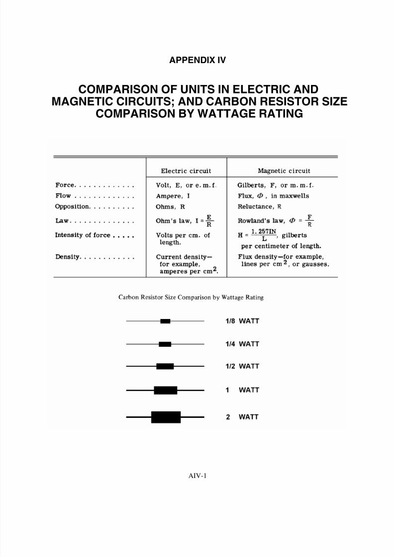
8/6/2019 NEETS MODULE 01 - Introduction to Matter, Energy, And Direct Current
http://slidepdf.com/reader/full/neets-module-01-introduction-to-matter-energy-and-direct-current 247/278
AIV-1
APPENDIX IV
COMPARISON OF UNITS IN ELECTRIC ANDMAGNETIC CIRCUITS; AND CARBON RESISTOR SIZE
COMPARISON BY WATTAGE RATING

8/6/2019 NEETS MODULE 01 - Introduction to Matter, Energy, And Direct Current
http://slidepdf.com/reader/full/neets-module-01-introduction-to-matter-energy-and-direct-current 248/278
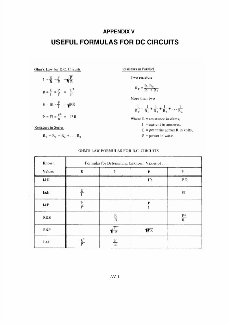
8/6/2019 NEETS MODULE 01 - Introduction to Matter, Energy, And Direct Current
http://slidepdf.com/reader/full/neets-module-01-introduction-to-matter-energy-and-direct-current 249/278
AV-1
APPENDIX V
USEFUL FORMULAS FOR DC CIRCUITS

8/6/2019 NEETS MODULE 01 - Introduction to Matter, Energy, And Direct Current
http://slidepdf.com/reader/full/neets-module-01-introduction-to-matter-energy-and-direct-current 250/278

8/6/2019 NEETS MODULE 01 - Introduction to Matter, Energy, And Direct Current
http://slidepdf.com/reader/full/neets-module-01-introduction-to-matter-energy-and-direct-current 251/278
Assignment Questions
Information: The text pages that you are to study are
provided at the beginning of the assignment questions.

8/6/2019 NEETS MODULE 01 - Introduction to Matter, Energy, And Direct Current
http://slidepdf.com/reader/full/neets-module-01-introduction-to-matter-energy-and-direct-current 252/278

8/6/2019 NEETS MODULE 01 - Introduction to Matter, Energy, And Direct Current
http://slidepdf.com/reader/full/neets-module-01-introduction-to-matter-energy-and-direct-current 253/278
1
ASSIGNMENT 1
Textbook assignment: Chapter 1, “Turning to Electricity,” pages 1-1 through 1-65.
_______________________________________________________________________________________
1-1. Matter can be found in which of the
following forms?
1. Solid
2. Liquid
3. Gaseous
4. Each of the above
1-2. A substance that CANNOT be reduced to a
simpler substance by chemical means is
called a/an
1. element
2. mixture
3. compound
4. solution
1-3. A molecule is the smallest possible particle
that retains the characteristic of which of
the following substances?
1. An element
2. A mixture
3. A compound
4. A solution
1-4. An atom is the smallest possible particle
that retains the characteristic of which of
the following substances?
1. An element
2. A mixture
3. A compound
4. A solution
1-5. What subatomic particle has a negative
charge and a small mass?
1. Proton
2. Electron
3. Positron
4. Neutron
1-6. What subatomic particle has a positive
charge and a large mass?
1. Proton
2. Electron
3. Positron
4. Neutron
1-7. What subatomic particle has no charge?
1. Proton
2. Electron
3. Positron
4. Neutron
1-8. When light is represented as a tiny packet
of energy, what are these packets of energy
called?
1. Angstroms
2. Photons
3. Wavelengths
4. Frequencies
1-9. If light energy collides with an orbiting
electron, what happens to the electron?
1. The electron will move around the
same orbit faster
2. The electron will jump to an orbit
further from the nucleus
3. The electron will jump to an orbit
closer to the nucleus
4. The electron will merge with the
nucleus

8/6/2019 NEETS MODULE 01 - Introduction to Matter, Energy, And Direct Current
http://slidepdf.com/reader/full/neets-module-01-introduction-to-matter-energy-and-direct-current 254/278
2
1-10. After the action described in question 1-9
occurs, the electron will return to the
condition it had before being acted upon by
the light. When the electron returns to this
condition, which of the following actionsoccurs?
1. The nucleus becomes lighter
2. The atom becomes an ion
3. Light energy is emitted4. The valence of the atom changes
1-11. The number of electrons in the outermost
shell of an atom determines which of the
following characteristics of the atom?
1. Valence
2. Atomic weight
3. Atomic number4. Number of shells
1-12. When an atom gains or loses an electron,
which of the following terms applies?
1. Unbalanced2. Lightened
3. Neutral
4. Ionized
1-13. What is the main difference between
conductors, semiconductors, andinsulators?
1. The temperature differences
2. The physical state of their mass3. The number of free electrons
4. The designations of the outer shells
1-14. A substance with an excess of electrons is
considered to be in what electrical state?
1. Neutral
2. Positive3. Negative
4. Discharged
1-15. Which of following actions describes the
easiest way to accumulate a static electric
charge?
1. Friction between two conductors2. Friction between two insulators
3. Pressure between two conductors4. Pressure between two insulators
1-16. An atom that contains 6 protons and 5electrons has what electrical charge?
1. Positive
2. Negative
3. Neutral4. Intermediate
1-17. How do "like" and "unlike" charges react to
one another?
1. Unlike charges repel each other, like
charges repel each other
2. Unlike charges attract each other, like
charges attract each other
3. Unlike charges repel each other, likecharges attract each other
4. Unlike charges attract each other, like
charges repel each other
1-18. What is/are the term(s) applied to the space
between and around charged bodies inwhich their influence is felt?
1. Electric field of force
2. Electrostatic field3. Dielectric field
4. Each of the above
1-19. Electrostatic lines of force are drawn in
which of the following manners?
1. Entering negative charge, entering
positive charge2. Entering negative charge, leaving
positive charge3. Leaving negative charge, leaving
positive charge
4. Leaving negative charge, entering
positive charge

8/6/2019 NEETS MODULE 01 - Introduction to Matter, Energy, And Direct Current
http://slidepdf.com/reader/full/neets-module-01-introduction-to-matter-energy-and-direct-current 255/278
3
1-20. Which of the following devices use
magnetism?
1. Batteries
2. Light bulbs3. High-fidelity speakers
4. Each of the above
1-21. Magnetic materials have which of the
following qualities?
1. They are attracted by magnets
2. They can be magnetized
3. Both 1 and 2 above
4. They are electrical insulators
1-22. Ferromagnetic materials have which of the
following qualities?
1. They are all alloys2. They all contain nickel
3. They make very weak magnets
4. They are relatively easy to magnetize
1-23. A material with low reluctance and highpermeability such as iron or soft steel is
used to make what type of magnet?
1. Temporary
2. Permanent
3. Residual4. Natural
1-24. The ability of a material to retain
magnetism is called
1. permeability
2. retentivity
3. reluctance
4. ionization
1-25. The law of magnetic poles states which of
the following relationships?
1. Like poles attract, unlike poles attract2. Like poles attract, unlike poles repel
3. Like poles repel, unlike poles repel
4. Like poles repel, unlike poles attract
1-26. The north indicating pole of a compass
needle is attracted to which of the
following poles of the earth?
1. The geographic north pole2. The magnetic north pole
3. The geographic south pole4. The magnetic south pole
1-27. Weber,s theory of magnetism assumes that
magnetic material is composed of
1. tiny molecular magnets
2. domains of magnetic influence
3. large blocks of material acting asmagnets
4. atoms with electrons spinning different
directions
1-28. According to the domain theory, if an atomwith 26 electrons has 20 electrons spinning
counterclock-wise, the atom is considered
to be
1. charged2. insulated
3. neutralized
4. magnetized
1-29. If a glass plate is placed over a magnet and
iron filings are sprinkled over the glass, apattern will be visible. What does this
pattern indicate?
1. The magnetic field2. The electrostatic field
3. The piezoelectric effect
4. The chemical reaction of the magnet
and the filings
1-30. An imaginary line used to illustrate a
magnetic effect is known as a/an
1. magnetic pole
2. force field pole3. magnetic line of force
4. electrostatic line of force

8/6/2019 NEETS MODULE 01 - Introduction to Matter, Energy, And Direct Current
http://slidepdf.com/reader/full/neets-module-01-introduction-to-matter-energy-and-direct-current 256/278
4
1-31. Which of the following is NOT a property
of magnetic lines of force?
1. They form closed loops around the
magnet2. They leave the magnetic material at
right angles to the surface3. They cross each other at right angles
4. They leave the north pole and enter the
south pole of the magnet
1-32. A magnetic shield or screen used to protect
a delicate instrument should be made of
which of the following materials?
1. Plastic
2. Copper
3. Soft iron
4. Aluminum
1-33. Bar magnets should be stored in which of
the following manners?
1. Separately
2. In pairs at 90 degree angles3. In pairs with north poles together
4. In pairs with a north pole and a south
pole together
1-34. What is the term applied to the ability to do
work?
1. Power
2. Energy
3. Voltage4. Current
1-35. An object that is in motion has what type of
energy?
1. Kinetic
2. Magnetic
3. Newtonian4. Potential
1-36. A book sitting on a shelf has what kind of
energy?
1. Kinetic
2. Potential3. Newtonian
4. Magnetic
1-37. Which of the following term(s) apply(ies)
to the difference of potential between twobodies?
1. Voltage
2. Electromotive force
3. Both 1 and 2 above4. Current
1-38. Which of the following terms is equal to
"2.1 kV?"
1. 210 V
2. 2100 V
3. 21,000 V
4. 2.1 x 10⁶ V
1-39. 250µV is equal to which of the following
terms?
1. .25 mV
2. .00025 V
3. 250 x 10-6
V4. All of the above
1-40. What is the general term that describes a
device which supplies a voltage?
1. A voltage source
2. A voltage supply
3. A voltage generator
4. A voltage producer
1-41. In addition to friction, magnetism, and
chemical action, which of the followingmethods can be used to produce a voltage?
1. Pressure
2. Heat
3. Light
4. Each of the above

8/6/2019 NEETS MODULE 01 - Introduction to Matter, Energy, And Direct Current
http://slidepdf.com/reader/full/neets-module-01-introduction-to-matter-energy-and-direct-current 257/278
5
________________________________________
IN ANSWERING QUESTIONS 1-42
THROUGH 1-46, MATCH THE VOLTAGE
PRODUCING METHOD LISTED IN COLUMNB TO THE DEVICE LISTED IN COLUMN A.
COLUMN A COLUMN B
1-42. Radio receiver,s
oscillator1. Heat
1-43. Thermocouple 2. Pressure
1-44. Automobile battery 3. Magnetism
1-45. Automobile generator 4. Chemical action
1-46. Flashlight cell
________________________________________
1-47. Current in an electric circuit is caused by
which of the following actions?
1. Electrons moving from negative topositive
2. Electrons moving from positive to
negative
3. Protons moving from negative to
positive
4. Protons moving from positive tonegative
1-48. When directed drift takes place, at what
speed does the effect take place?
1. 100,000 miles per hour
2. 186,000 miles per second
3. 300,000 meters per hour
4. 500,000 meters per second
1-49. If the voltage in a circuit increases, what
happens to the current?
1. Current increases2. Current decreases
3. Current remains the same
4. Current fluctuates rapidly
1-50. Which of the following values is equal to
100mA?
1. 1.0 ampere
2. 10.0 amperes3. 0.10 ampere
4. 0.01 ampere
1-51. What symbol is used to represent the ohm?
1. A
2. O
3. µ
4. !
1-52. If low weight is the major factor, which of
the following materials should be used as a
conductor?
1. Aluminum2. Copper
3. Silver
4. Gold
1-53. What material is MOST widely used as aconductor in electrical equipment?
1. Aluminum
2. Copper
3. Silver
4. Gold
1-54. Resistance of a conductor will increase with
which of the following changes to the
cross-sectional area and length of theconductor?
1. Cross-sectional area is increased, length
is increased
2. Cross-sectional area is increased, lengthis decreased
3. Cross-sectional area is decreased,
length is increased4. Cross-sectional area is decreased,
length is decreased

8/6/2019 NEETS MODULE 01 - Introduction to Matter, Energy, And Direct Current
http://slidepdf.com/reader/full/neets-module-01-introduction-to-matter-energy-and-direct-current 258/278
6
1-55. A material whose resistance decreases as
the temperature increases has what
temperature coefficient?
1. Positive2. Negative
3. Zero4. Neutral
1-56. A material whose resistance remainsconstant as the temperature increases has
what temperature coefficient?
1. Positive
2. Negative3. Zero
4. Neutral
1-57. Which of the following units is NOT a unitof conductance?
1. Siemens
2. S
3. G
4. Ohm
1-58. Resistance bears which, if any, of the
following relationships to conductance?
1. A direct relationship
2. A reciprocal relationship3. An inverse square relationship
4. None
THIS SPACE LEFT BLANKINTENTIONALLY.
1-59. Which of the following schematic symbols
is used to represent a resistor?
1-60. How is the ability of a resistor to dissipateheat indicated?
1. By the wattage rating
2. By the voltage rating
3. By the resistance rating
4. By the tolerance
1-61. Carbon resistors have which of the
following disadvantages?
1. A high cost factor
2. An extremely large physical size3. The resistance value changes with age
4. A limited range of resistance values
1-62. Which of the following types of resistors
will overcome the disadvantages of a
carbon resistor?
1. Rheostat
2. Potentiometer
3. Molded composition
4. Wirewound resistor
1-63. What is the total number of connections on
(a) a rheostat and (b) a potentiometer?
1. (a) Two (b) two
2. (a) Two (b) three
3. (a) Three (b) two
4. (a) Three (b) three

8/6/2019 NEETS MODULE 01 - Introduction to Matter, Energy, And Direct Current
http://slidepdf.com/reader/full/neets-module-01-introduction-to-matter-energy-and-direct-current 259/278
7
1-64. Which, if any, of the following types of
variable resistors is used to control a large
amount of current?
1. Rheostat2. Potentiometer
3. Wirewound potentiometer4. None of the above
1-65. A carbon resistor is color-coded orange,orange, orange. What is the resistance
value of this resistor?
1. 2.2 k !
2. 3.3 k ! 3. 33.0 k !
4. 440.0 k !
1-66. What are the allowable limits of ohmicvalue in a resistor color coded blue, green,yellow, gold?
1. 682.5 k ! to 617.5 k !
2. 715.0 k ! to 585.0 k !
3. 7.98 M! to 7.22 M! 4. 8.36 M! to 6.84 M!
1-67. Of the following, which color of the fifth
band on a resistor indicates the LEAST
chance of failure?
1. Red
2. Brown
3. Yellow
4. Orange
THIS SPACE LEFT BLANK
INTENTIONALLY.
Figure 1A.—Resistor with color coding.
IN ANSWERING QUESTIONS 1-68
THROUGH 1-70, REFER TO FIGURE 1A.
1-68. What is the ohmic value of the resistor?
1. 8!
2. 79! 3. 790!
4. 800!
1-69. What is the specified tolerance of the
resistor?
1. 1%
2. 5%3. 10%
4. 20%
1-70. What is the specified reliability of the
resistor?
1. 1.0%2. 0.1%
3. 0.01%
4. 0.001%

8/6/2019 NEETS MODULE 01 - Introduction to Matter, Energy, And Direct Current
http://slidepdf.com/reader/full/neets-module-01-introduction-to-matter-energy-and-direct-current 260/278
8
ASSIGNMENT 2
Textbook assignment: Chapter 2, “Batteries,” pages 2-1 through 2-29._____________________________________________________________________________________________
2-1. Which of the following is the purpose of
an electrical cell?
1. To change mechanical energy to
electrical energy
2. To change chemical energy to
electrical energy
3. To change electrical energy to
mechanical energy
4. To change electrical energy to
chemical energy
2-2. What are the three basic parts of a cell?
1. Electrodes, electrolyte, container
2. Electrodes, acid, water
3. Anode, cathode, ions
4. Anode, load, depolarizer
_______________________________________
IN ANSWERING QUESTIONS 2-3
THROUGH 2-6, SELECT THE PHRASE
FROM THE FOLLOWING LIST THAT
DESCRIBES THE PART OF A CELL IN THEQUESTION.
A. PARTS OF
A CELL
B. DESCRIPTIVE
PHRASE
2-3. Electrolyte 1. negative electrode
2-4. Container 2. positive electrode
2-5. Anode 3. solution acting
upon the electrode
2-6. Cathode 4. mounting for the
electrode
_______________________________________
2-7. What term is given to the process that
takes place inside a cell?
1. Electromagnetic action
2. Piezoelectric action
3. Electromechanical action
4. Electrochemical action
2-8. With respect to recharging a primary or
secondary cell, of the following
statements, which one is correct?
1. The secondary cell can be recharged
by passing current through it in the
proper direction
2. The primary cell can be recharged by
passing current through it in the
proper direction
3. The secondary cell can only be
recharged by changing the electrodes
4. The primary cell can only be
recharged by changing the electrolyte
2-9. What determines the amount of currentthat a cell can deliver to the external
circuit?
1. The internal resistance of the cell only
2. The resistance of the external load
only
3. The circuit resistance and the internal
resistance of the cell
4. The circuit capacitance and number of
free electrons in the load

8/6/2019 NEETS MODULE 01 - Introduction to Matter, Energy, And Direct Current
http://slidepdf.com/reader/full/neets-module-01-introduction-to-matter-energy-and-direct-current 261/278
9
2-10. Which of the following actions will lower
the internal resistance of a cell?
1. Decreasing the size of the electrodes
2. Increasing the size of the electrodes3. Increasing the spacing between the
electrodes4. Increasing the resistance of the
electrolyte
2-11. What causes negative ions to be attracted
to the cathode of a primary cell while the
cell is discharging?
1. A negative charge caused by a loss ofelectrons
2. A negative charge caused by an
excess of electrons
3. A positive charge caused by a loss ofelectrons
4. A positive charge caused by an excess
of electrons
2-12. What causes hydrogen to be attracted to
the anode of a primary cell when the cellis discharging?
1. A negative charge caused by a loss of
electrons
2. A negative charge caused by an
excess of electrons3. A positive charge caused by a loss of
electrons
4. A positive charge caused by an excess
of electrons
2-13. What causes the cathode to be "eaten
away" in the primary cell while the cell is
discharging?
1. The material of the cathode combines
with the negative ions to form a new
substance.2. The material of the cathode dissolves
in the electrolyte.3. The material of the cathode leaves the
negative terminal of the cell and goes
through the load to the anode.
4. Bacteria in the electrolyte erodes the
material in the cathode.
2-14. The primary cell is completely discharged
when which of the following conditions
exists?
1. The cathode is completely eaten away2. The active ingredient in the electrolyte
is used up3. The voltage of the cell is reduced to
zero
4. Each of the above
2-15. In a zinc-carbon primary cell, what is the
function of the carbon electrode?
1. To generate electrons2. To supply a return path for current
3. To speed electrolysis
4. To collect hydrogen
2-16. The lead-acid cell is an example of whichof the following types of cells?
1. The dry cell
2. The voltaic cell
3. The primary cell4. The secondary cell
2-17. In a fully charged lead-acid cell, what is
the composition of the anode, cathode,
and electrolyte respectively?
1. Zinc, carbon, and water
2. Carbon, lead, sulfuric acid and water
3. Lead peroxide, sponge lead, sulfuric
acid, and water4. Nickel, cadmium, potassium
hydroxide, and water

8/6/2019 NEETS MODULE 01 - Introduction to Matter, Energy, And Direct Current
http://slidepdf.com/reader/full/neets-module-01-introduction-to-matter-energy-and-direct-current 262/278
10
2-18. Which of the following actions will
recharge a secondary cell?
1. Adding more water to the electrolyte
2. Adding more active ingredient to theelectrolyte
3. Connecting the negative terminal of avoltage source to the cathode of the
cell and the positive terminal of the
voltage source to the anode of the cell4. Connecting the negative terminal of a
voltage source to the anode of the cell
and the positive terminal of the
voltage source to the cathode of the
cell
A. Sulfuric acid decreasing
B. Sulfuric acid increasing
C. Sponge lead decreasing
D. Sponge lead increasing
E. Lead peroxide decreasing
F. Lead peroxide increasing
G. Lead sulfate decreasing
H. Lead sulfate increasing
Figure 2A.—Lead acid chemical actions.
IN ANSWERING QUESTIONS 2-19 AND
2-20, REFER TO FIGURE 2A. SELECT THE
CORRECT CHEMICAL ACTIONS WITHIN ALEAD-ACID CELL FOR THE CONDITION
STATED IN EACH QUESTION.
2-19. The cell is discharging.
1. A, C, E, H
2. A, D, E, G
3. B, C, F, G
4. B, D, F, H
2-20. The cell is charging.
1. A, C, F, H
2. B, C, F, H
3. A, D, F, G4. B, D, F, G
2-21. When all the lead sulfate in a lead-acid
cell is converted to sulfuric acid, lead
peroxide, and sponge lead, what is thecondition of the cell?
1. Fully charged
2. Discharged
3. Sulfated4. Unusable
2-22. Polarization has what effects on an
electrical cell?
1. Decreases internal resistance, thereby
increasing the output voltage
2. Decreases internal resistance, thereby
decreasing the output voltage
3. Increases internal resistance, therebyincreasing the output voltage
4. Increases internal resistance, thereby
decreasing the output voltage
2-23. Which of the following methods is used to
control polarization in a cell?
1. Venting the cell
2. Heating the electrolyte
3. Adding mercury to the electrodematerial
4. Using an electrolyte that absorbs
oxygen
2-24. Which of the following is caused by localaction in a cell?
1. Shelf life is reduced2. Hydrogen is generated in large
quantities3. Impurities rise to the surface of the
electrolyte
4. Mercury coating of the zinc electrode
is worn away

8/6/2019 NEETS MODULE 01 - Introduction to Matter, Energy, And Direct Current
http://slidepdf.com/reader/full/neets-module-01-introduction-to-matter-energy-and-direct-current 263/278
11
2-25. In a dry cell, what is the consistency of the
electrolyte?
1. Solid
2. Liquid3. Paste
4. Powder
2-26. What serves as the cathode in a common
type of dry cell?
1. Carbon electrode
2. Zinc container
3. Steel cover
4. Nickel terminal
2-27. How should the dry cell be stored to
obtain maximum shelf life?
1. In a dark container2. In a heated cabinet
3. In a ventilated area
4. In a refrigerated space
2-28. The blotting paper in a dry cell serveswhich of the following purposes?
1. Separates the paste from the zinc
2. Permits the electrolyte from the paste
to filter through to the zinc slowly
3. Both 1 and 2 above4. Keeps the electrolyte dry
2-29. Of the following characteristics, which
one describes the mercury cell?
1. It is physically one of the largest cells
2. It has a very stable output voltage
3. It is designed to be rechargeable
4. It produces a large amount of currentbut has a short shelf life
2-30. Which of the following describes theshorting of a cell?
1. Decreasing the length of a cell
2. Connecting the anode and cathode
together without a load
3. Using the cell below its full potential
4. Providing a recharge voltage that isnot sufficient to recharge the cell
2-31. What is/are the advantages(s) of using a
manganese-dioxide-alkaline- zinc cell
over the zinc-carbon cell?
1. Better voltage stability2. Longer storage life
3. Operates over a wide temperaturerange
4. All the above
2-32. What is the common name for manganese-
dioxide-alkaline-zinc cell?
1. Alkaline cell
2. Long-life cell3. Moz cell
4. Manganese-dioxide cell
2-33. Which of the following factors should beconsidered when selecting a primary cellas a power source?
1. Power requirement
2. Type of electrolyte used
3. Container material4. All of the above
2-34. Of the following types of cells, which one
is a primary cell?
1. Nickel cadmium2. Silver zinc
3. Lithium organic
4. Silver cadmium
2-35. Which of the following is/are the
difference(s) in the construction of a
NICAD cell as compared to a lead-acid
cell?
1. The electrolyte used
2. The material of the anode
3. The material of the cathode4. All of the above

8/6/2019 NEETS MODULE 01 - Introduction to Matter, Energy, And Direct Current
http://slidepdf.com/reader/full/neets-module-01-introduction-to-matter-energy-and-direct-current 264/278
12
2-36. What is the most common use of a silver-
zinc cell?
1. Flashlight batteries
2. Automobile batteries3. Aircraft storage batteries
4. Emergency equipment batteries
2-37. In addition to the nickel-cadmium and
silver-zinc cells, which of the followingcells uses potassium hydroxide as the
active ingredient in the electrolyte?
1. Lead-acid cell
2. Silver-cadmium3. Lithium-inorganic cell
4. Magnesium-manganese dioxide cell
2-38. What is the minimum number of cellsnecessary to form a battery?
1. One
2. Two
3. Three
4. Four
Figure 2B.—Battery consisting of five cells.
IN ANSWERING QUESTIONS 2-39 AND
2-40, REFER TO FIGURE 2B. EACH CELL IS
1.5 VOLTS AND HAS A CAPACITY OF 1/8
AMPERE.
2-39. What type of connection is used to
combine the cells?
1. Series
2. Parallel
3. Series-parallel
2-40. What is the (a) voltage output and
(b) current capacity of the circuit?
1. (a) 1.5 volts (b) 1/8 ampere
2. (a) 1.5 volts (b) 5/8 ampere3. (a) 7.5 volts (b) 1/8 ampere
4. (a) 7.5 volts (b) 5/8 ampere
Figure 2C.—Five cells connected to form a battery.
IN ANSWERING QUESTIONS 2-41 AND
2-42, REFER TO FIGURE 2C. EACH CELL IS
1.5 VOLTS AND HAS A CAPACITY OF 1/8
AMPERE.
2-41. What type of connection is used to
combine the cells?
1. Series
2. Parallel
3. Series-parallel
2-42. What is the (a) voltage output and
(b) current capacity of the circuit?
1. (a) 1.5 volts (b) 1/8 ampere
2. (a) 1.5 volts (b) 5/8 ampere
3. (a) 7.5 volts (b) 1/8 ampere
4. (a) 7.5 volts (b) 5/8 ampere

8/6/2019 NEETS MODULE 01 - Introduction to Matter, Energy, And Direct Current
http://slidepdf.com/reader/full/neets-module-01-introduction-to-matter-energy-and-direct-current 265/278
13
2-43. Which of the following diagrams shows
the proper connections for obtaining 6
volts at 1/4 ampere? (Each cell is 1.5 volts
and has a capacity of 1/8 amp.)
Figure 2D.—Battery consisting of 12 cells.
IN ANSWERING QUESTIONS 2-44 AND
2-45, REFER TO FIGURE 2D. EACH CELLEQUALS 1.5 VOLTS AND HAS A
CAPACITY OF 1/8 AMPERE.
2-44. What type of connection is used tocombine the cells?
1. Series
2. Parallel
3. Series-parallel
2-45. What is the (a) voltage output and
(b) current capacity of the circuit?
1. (a) 1.5 volts (b) 1.5 amperes
2. (a) 4.5 volts (b) 1/2 ampere3. (a) 9 volts (b) 1/4 ampere
4. (a) 18 volts (b) 1/8 ampere
2-46. What is the first step in performing
maintenance on a secondary-cell battery?
1. Check the level of the electrolyte
2. Check the technical manual for
information on the specific type of
battery3. Check the terminals for cleanliness
and good electrical connection
4. Check the battery case for cleanliness
and evidence of damage
2-47. When a hydrometer is used to check the
specific gravity of the electrolyte in a
battery, to what level should the
electrolyte be drawn?
1. Enough to just wet the float
2. Enough so the float will rise without
entering the suction bulb
3. Enough so the top one-third of the
float will rise into the suction bulb
4. Enough so the float is completelycovered by the electrolyte
2-48. To flush a hydrometer, which of the
following liquids should be used?
1. Sulfuric acid
2. Salt water
3. Fresh water
4. A solution of baking soda and water
2-49. If the electrolyte level in a battery is low,
what should be added to the electrolyte tobring it to the proper level?
1. Tap water
2. Sulfuric acid
3. Potassium hydroxide
4. Distilled water

8/6/2019 NEETS MODULE 01 - Introduction to Matter, Energy, And Direct Current
http://slidepdf.com/reader/full/neets-module-01-introduction-to-matter-energy-and-direct-current 266/278
14
2-50. Which one of the following safety
precautions for batteries is NOT correct?
1. Terminals should be electrically
connected together beforetransporting a battery
2. Care should be taken to prevent thespilling of electrolyte
3. Smoking, open flames, and electrical
sparks are prohibited around chargingbatteries
4. Protective clothing, such as rubber
apron, rubber gloves, and face shield,
should be worn when working on
batteries
2-51. If electrolyte comes in contact with the
skin, what first aid treatment should be
given immediately to the affected area?
1. Cover with petroleum jelly
2. Wrap with a sterile bandage
3. Apply an antiseptic lotion
4. Flush with fresh water
2-52. A battery with a capacity of 600
ampere-hours should provide 3 amperes
for a maximum of how many hours?
1. 100 hr
2. 200 hr3. 300 hr
4. 600 hr
2-53. A battery is rated according to a 20-hourrate of discharge at 300 ampere-hours.
Which of the following currents is the
maximum current that will allow the
battery to deliver its rated capacity?
1. 15 amperes
2. 20 amperes
3. 25 amperes4. 30 amperes
2-54. Which of the following types of routine
charges follows the nameplate data in
restoring a battery to its charged condition
during the ordinary cycle of operation?
1. Initial
2. Floating3. Normal
4. Fast
THIS SPACE LEFT BLANK
INTENTIONALLY.
8/6/2019 NEETS MODULE 01 - Introduction to Matter, Energy, And Direct Current
http://slidepdf.com/reader/full/neets-module-01-introduction-to-matter-energy-and-direct-current 267/278
15
_______________________________________
IN ANSWERING QUESTIONS 2-55
THROUGH 2-58, MATCH THE
DESCRIPTION GIVEN IN THE FOLLOWINGLIST WITH THE TYPE OF BATTERY
CHARGE IN THE QUESTION.
A. TYPE OF
CHARGE
B. DESCRIPTION
2-55. Initial charge 1. Used in emergency
only
2-56. Equalizingcharge
2. Used periodically aspart of a maintenance
routine
2-57. Floatingcharge
3. Used to keep a batteryat full charge whilethe battery is idle
2-58. Fast charge 4. Used after electrolyte
is added to a
dry-shipped battery_______________________________________
2-59. If violent gassing occurs during the
charging of a battery, which of the
following actions should be taken?
1. Increase the room ventilation
2. Decrease the room temperature
3. Increase the charging rate
4. Decrease the charging rate
2-60. If a battery is being charged at the proper
rate, which, if any of the following types
of gassing should occur?
1. Steady gassing
2. Intermittent gassing
3. Violent gassing4. None

8/6/2019 NEETS MODULE 01 - Introduction to Matter, Energy, And Direct Current
http://slidepdf.com/reader/full/neets-module-01-introduction-to-matter-energy-and-direct-current 268/278
16
ASSIGNMENT 3
Textbook assignment: Chapter 3, “Direct Current,” pages 3-1 through 3-126.
_____________________________________________________________________________________
Figure 3A.—Basic circuit.
IN ANSWERING QUESTIONS 3-1
THROUGH 3-3, REFER TO FIGURE 3A.
3-1. What parts of the circuit represent the
(a) source and (b) load?
1. (a) Es (b) S1
2. (a) Es (b) R1
3. (a) S1 (b) R1 4. (a) S1 (b) Es
3-2. Which of the following terms describes
the circuit condition?
1. Partially shorted
2. Partially open
3. Shorted
4. Open
3-3. Which of the following terms describes
the figure 3A?
1. Parts layout
2. Exploded view
3. Wiring diagram
4. Schematic diagram
3-4. If circuit voltage is held constant, circuit
current will react in what manner as theresistance (a) increases, and (b) decreases?
1. (a) Increase (b) decrease
2. (a) Increase (b) increase
3. (a) Decrease (b) decrease4. (a) Decrease (b) increase
3-5. If circuit resistance is held constant,
circuit current will react in what manner
as the voltage (a) increases, and(b) decreases?
1. (a) Increase (b) decrease
2. (a) Increase (b) increase
3. (a) Decrease (b) decrease4. (a) Decrease (b) increase
3-6. According to Ohm,s law, what formula
should be used to calculate circuit voltage
if resistance and current value are known?

8/6/2019 NEETS MODULE 01 - Introduction to Matter, Energy, And Direct Current
http://slidepdf.com/reader/full/neets-module-01-introduction-to-matter-energy-and-direct-current 269/278
17
Figure 3B.—Graph of current and voltage.
IN ANSWERING QUESTIONS 3-7 AND 3-8,
REFER TO FIGURE 3B.
3-7. If the current is 15 amperes, what is thevalue of the voltage?
1. 50 V
2. 75 V
3. 100 V
4. 150 V
3-8. If the voltage is 200 volts, what is the
value of the current?
1. 10 A
2. 20 A
3. 30 A
4. 40 A
3-9. Which of the following terms applies to
the rate at which an electrical force causes
motion?
1. Power
2. Energy
3. Inertia
4. Each of the above
3-10. Which of the following circuit quantities
can be varied ONLY by varying one of
the other circuit quantities?
1. Voltage2. Current
3. Resistance4. Each of the above
3-11. Which of the following is a correctformula for determining power in an
electrical circuit?
3-12. What is the current in a circuit with
15 ohms of resistance that uses 135 watts
of power?
1. 10 A
2. 15 A
3. 3 A
4. 9 A
3-13. What is the total power used by a 15-ohm
resistor with 4 amps of current?
1. 60 W
2. 240 W3. 360 W
4. 900 W
3-14. What type of resistor should be used in
question 3-13?
1. Carbon
2. Wirewound
3. Precision
4. Composition

8/6/2019 NEETS MODULE 01 - Introduction to Matter, Energy, And Direct Current
http://slidepdf.com/reader/full/neets-module-01-introduction-to-matter-energy-and-direct-current 270/278
18
3-15. How much total energy is converted by a
l-horsepower motor in 10 hours?
1. 7.46 kWh
2. 8.32 kWh3. 8.59 kWh
4. 9.32 kWh
3-16. If the energy used by the motor in
question 3-15 is 9.5 kWh, what is theefficiency of the motor?
1. .981
2. .904
3. .8764. .785
Figure 3C.—Series circuit.
IN ANSWERING QUESTIONS 3-17
THROUGH 3-23, REFER TO FIGURE 3C.
3-17. What is the total circuit resistance (R)?
1. 20!
2. 60!
3. 180!
4. 240!
3-18. If the circuit current is 3 amps, what is thesource voltage (Es)?
1. 60 V
2. 180 V
3. 540 V
4. 720 V
3-19. What is the total voltage dropped by each
resistor in question 3-18?
1. 20 V
2. 60 V3. 180 V
4. 540 V
3-20. If the current decreases to 2 amps, what is
the total voltage drop across each resistor?
1. 120 V
2. 230 V
3. 310 V
4. 400 V
3-21. What would have to be done to the circuit
to cause the current to decrease to 2 amps?
1. The source voltage would have to beincreased
2. The source voltage would have to be
decreased
3. The resistance of R1 would have to be
decreased4. One of the resistors would have to be
removed from the circuit
3-22. If the circuit current is 2 amps, what is the
total power used by each resistor?
1. 240 W
2. 460 W
3. 620 W
4. 800 W
3-23. What is the total power used in the circuit
if Es = 360 V?
1. 720 W2. 1380 W
3. 1860 W
4. 2400 W

8/6/2019 NEETS MODULE 01 - Introduction to Matter, Energy, And Direct Current
http://slidepdf.com/reader/full/neets-module-01-introduction-to-matter-energy-and-direct-current 271/278
19
3-24. When Kirchoff ,s voltage law is used to
assign polarities to the voltage drop across
a resistor, which of the following
references is used to indicate the end of
the resistor that the current enters?
1. Ground2. Neutral
3. Negative
4. Positive
Figure 3D.—Multiple source circuit.
IN ANSWERING QUESTIONS 3-25 AND
3-26, REFER TO FIGURE 3D.
3-25. What is the effective source voltage?
1. 15 V
2. 25 V
3. 50 V
4. 75 V
3-26. What is the total amount and direction of
current through R 3?
1. 1.0 A from Y to X
2. 1.0 A from X to Y
3. .33 A from Y to X4. .33 A from X to Y
3-27. Which of the following terms applies to a
circuit in which there is NO complete
path for current?
1. Open2. Short
3. Closed4. Grounded
3-28. A circuit in which the resistance is almostzero ohms is referred to by which of the
following terms?
1. Open
2. Short3. Closed
4. Broken
THIS SPACE LEFT BLANK
INTENTIONALLY.

8/6/2019 NEETS MODULE 01 - Introduction to Matter, Energy, And Direct Current
http://slidepdf.com/reader/full/neets-module-01-introduction-to-matter-energy-and-direct-current 272/278
20
Figure 3E.—Series circuit and source resistance.
IN ANSWERING QUESTIONS 3-29
THROUGH 3-32, REFER TO FIGURE 3E.
3-29. If R2 has a short circuit, what will most
likely happen to the circuit?
1. R1 will be destroyed2. Es will increase
3. V will indicate O volts
4. S1 will automatically open
3-30. What is the total voltage drop across Ri when the switch is closed?
1. 2.5 V2. 6.5 V
3. 97.5 V4. 100.0 V
3-31. What will the meter indicate with (a) S1
open, and (b) S1 closed?
1. (a) 100 V (b) 100 V
2. (a) 97.5 V (b) 100 V
3. (a) 100 V (b) 97.5 V
4. (a) 97.5 V (b) 97.5 V
3-32. To achieve maximum power transfer in
the circuit, which of the following
conditions must be met?
1. Ri = RL 2. Is = IL
3. Es = EL 4. Ks = KL
3-33. Maximum power is transferred from asource to a load when the value of the
load resistance is of what value when
compared to the source resistance?
1. Equal2. Twice
3. One-half
4. Several times
3-34. When maximum power is transferred froma source to a load, what is the efficiency
of power transfer?
1. 5%
2. 25%3. 50%
4. 95%
3-35. A circuit consists of three resistors
connected in parallel. R1 = 30 ohms,
R2 = 15 ohms, and R3 = 10 ohms. If thecurrent through R2 = 4 amperes, what is
the total source voltage?
1. 20 V2. 60 V
3. 120 V
4. 220 V
3-36. What is the relationship of total current tothe current through a component in (a) a
series circuit, and (b) a parallel circuit?
1. (a) Divides (b) divides
2. (a) Divides (b) equals3. (a) Equals (b) equals
4. (a) Equals (b) divides

8/6/2019 NEETS MODULE 01 - Introduction to Matter, Energy, And Direct Current
http://slidepdf.com/reader/full/neets-module-01-introduction-to-matter-energy-and-direct-current 273/278
21
3-37. If a current has a negative polarity when
Kirchoff ,s current law is applied, which of
the following, statements is true of the
current?
1. It is from a battery
2. It is from a generator3. It is entering a junction
4. It is leaving a junction
3-38. Three equal resistors are connected in
parallel and each resistor has an ohmic
value of 300 ohms. What is the equivalent
resistance of the circuit?
1. 100!
2. 150!
3. 600!
4. 900!
3-39. Three resistors with ohmic values of
120 ohms, 60 ohms, and 40 ohms are
connected in parallel. What is the
equivalent resistance of the circuit?
1. 10!
2. 20!
3. 30!
4. 40!
3-40. Two resistors with ohmic values of90 ohms and 45 ohms are connected in
parallel. What is the equivalent resistance
of the circuit?
1. 10!
2. 20!
3. 30!
4. 40!
3-41. Which of the following terms describes a
single resistor that represents a complex
circuit?
1. Equal resistor2. Phantom resistor
3. Schematic resistor
4. Equivalent resistor
THIS SPACE LEFT BLANK
INTENTIONALLY.

8/6/2019 NEETS MODULE 01 - Introduction to Matter, Energy, And Direct Current
http://slidepdf.com/reader/full/neets-module-01-introduction-to-matter-energy-and-direct-current 274/278
22
Figure 3F.—Parallel circuit.
IN ANSWERING QUESTIONS 3-42
THROUGH 3-46, REFER TO FIGURE 3F.
3-42. What is the value of Es?
1. 336 V
2. 300 V
3. 240 V4. 120 V
3-43. What is the value of current through R2?
1. 1 A2. 2 A
3. 3 A
4. 4 A
3-44. What is the approximate value of total
resistance?
1. 8!
2. 37!
3. 112!
4. 257!
3-45. What is the value of total power?
1. 1.2 kW2. 1.5 kW
3. 1.8 kW
4. 2.0 kW
3-46. What is the total power consumed by R3?
1. 108 W
2. 240 W
3. 360 W4. 1200 W
Figure 3G.—Series-parallel circuit.
IN ANSWERING QUESTIONS 3-47
THROUGH 3-49, REFER TO FIGURE 3G.
3-47. What is the value of the total resistance?
1. 3.6!
2. 15! 3. 34!
4. 40!
3-48. What is the total power used in the circuit?
1. 22.5 W
2. 26.5 W
3. 60.0 W
4. 250.0 W
3-49. What is the total voltage drop across R3?
1. 8 V
2. 12 V3. 18 V
4. 30 V
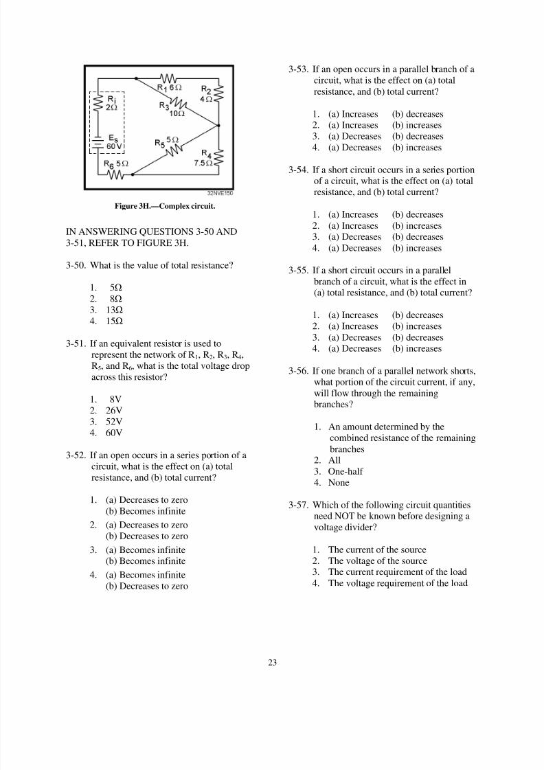
8/6/2019 NEETS MODULE 01 - Introduction to Matter, Energy, And Direct Current
http://slidepdf.com/reader/full/neets-module-01-introduction-to-matter-energy-and-direct-current 275/278
23
Figure 3H.—Complex circuit.
IN ANSWERING QUESTIONS 3-50 AND
3-51, REFER TO FIGURE 3H.
3-50. What is the value of total resistance?
1. 5!
2. 8!
3. 13!
4. 15!
3-51. If an equivalent resistor is used to
represent the network of R1, R2, R3, R4,
R5, and R6, what is the total voltage drop
across this resistor?
1. 8V
2. 26V
3. 52V
4. 60V
3-52. If an open occurs in a series portion of a
circuit, what is the effect on (a) total
resistance, and (b) total current?
1. (a) Decreases to zero
(b) Becomes infinite
2. (a) Decreases to zero
(b) Decreases to zero3. (a) Becomes infinite
(b) Becomes infinite
4. (a) Becomes infinite
(b) Decreases to zero
3-53. If an open occurs in a parallel branch of a
circuit, what is the effect on (a) total
resistance, and (b) total current?
1. (a) Increases (b) decreases2. (a) Increases (b) increases
3. (a) Decreases (b) decreases4. (a) Decreases (b) increases
3-54. If a short circuit occurs in a series portionof a circuit, what is the effect on (a) total
resistance, and (b) total current?
1. (a) Increases (b) decreases
2. (a) Increases (b) increases3. (a) Decreases (b) decreases
4. (a) Decreases (b) increases
3-55. If a short circuit occurs in a parallelbranch of a circuit, what is the effect in(a) total resistance, and (b) total current?
1. (a) Increases (b) decreases
2. (a) Increases (b) increases
3. (a) Decreases (b) decreases4. (a) Decreases (b) increases
3-56. If one branch of a parallel network shorts,
what portion of the circuit current, if any,
will flow through the remaining
branches?
1. An amount determined by the
combined resistance of the remaining
branches2. All
3. One-half
4. None
3-57. Which of the following circuit quantitiesneed NOT be known before designing a
voltage divider?
1. The current of the source
2. The voltage of the source3. The current requirement of the load
4. The voltage requirement of the load

8/6/2019 NEETS MODULE 01 - Introduction to Matter, Energy, And Direct Current
http://slidepdf.com/reader/full/neets-module-01-introduction-to-matter-energy-and-direct-current 276/278
24
______________________________________
THE FOLLOWING INFORMATION IS TO
BE USED IN ANSWERING QUESTIONS 3-58
THROUGH 3-60: A VOLTAGE DIVIDER ISREQUIRED TO SUPPLY A SINGLE LOAD
WITH +150 VOLTS AND 300 MILLIAMPSOF CURRENT. THE SOURCE VOLTAGE IS
250 VOLTS. (HINT: DRAW THE CIRCUIT.)
______________________________________
3-58. What should be the value of the bleeder
current?
1. 3 A2. 300 mA
3. 30 mA
4. 3 mA
3-59. What should be the ohmic value of thebleeder resistor?
1. 50
2. 500
3. 5 k4. 50 k
3-60. What is the value of total current?
1. 303 mA
2. 330 mA3. 600 mA
4. 3300 mA
Figure 3I.—Voltage divider.
IN ANSWERING QUESTIONS 3-61
THROUGH 3-66, REFER TO FIGURE 3I.
3-61. Why must the value of R1 be calculated
first?
1. For convenience
2. The current through R2 depends on the
value of R1
3. The voltage drop across R1depends on
the value of load 14. In any circuit, values for resistors
labeled R1 are calculated first
3-62. How is the current through R2 calculated?
1. By adding IR1 and the current
requirement of load 1
2. By adding the current requirements of
load 1 and load 2
3. By subtracting the current requirement
of load 1 from the current
requirement of load 2
4. By subtracting the current requirement
of load 2 from the current
requirement of load 1

8/6/2019 NEETS MODULE 01 - Introduction to Matter, Energy, And Direct Current
http://slidepdf.com/reader/full/neets-module-01-introduction-to-matter-energy-and-direct-current 277/278
25
3-63. How is the voltage drop across R2
calculated?
1. By adding the voltage requirements of
load 1 and load 22. By subtracting the voltage drops
across R5 and R 3 from the sourcevoltage
3. By subtracting the voltage
requirement of load 1 from thevoltage requirement of load 2
4. By subtracting the voltage
requirements of load 1 and load 2
from the source voltage
3-64. What is the minimum wattage rating
required for R5?
1. 1 W2. 2 W3. 1/2 W
4. 1/4 W
3-65. What is the total power supplied by the
source?
1. 3.765 W
2. 7.965 W
3. 8.209 W
4. 8.965 W
3-66. What is the purpose of using the series-
parallel network consisting of R3, R4, and
R5 in place of a single resistor?
1. It provides the desired resistance with
resistor values that are easily
obtainable
2. It provides the close tolerance
required for the circuit3. It is more reliable than the use of a
single resistor
4. It costs less by using three resistors oflower wattage rating than a single,
large power resistor
3-67. A single voltage divider provides both
negative and positive voltages from a
single source voltage through the use of a
1. ground between two of the dividingresistors
2. ground to the positive terminal of thesource
3. ground to the negative terminal of the
source4. ground to the input of all loads
requiring a negative voltage
3-68. Which of the following voltages are
considered dangerous?
1. Voltages above 115 volts only
2. Voltages above 230 volts only
3. Voltages above 450 volts only4. All voltages
3-69. If you discover a possible malfunction in
an electric circuit, which of the following
actions should be taken?
1. Attempt repairs yourself
2. Report the malfunction to a qualified
technician
3. Ignore the malfunction unless you
were assigned to repair it
4. Secure the circuit immediately byremoving power at the nearest switch
3-70. If a person has stopped breathing and
there is NO detectable heartbeat, whoshould perform CPR?
1. Medical personnel only
2. The first person on the scene
3. Emergency Medical Technicians only4. Trained, qualified personnel only

8/6/2019 NEETS MODULE 01 - Introduction to Matter, Energy, And Direct Current
http://slidepdf.com/reader/full/neets-module-01-introduction-to-matter-energy-and-direct-current 278/278