negative skin friction on piles - guru nanak dev ...igs/ldh/conf/2009/articles/v2-0_01.pdf ·...
TRANSCRIPT

Negative Skin Friction on Piles
827
NEGATIVE SKIN FRICTION ON PILES
C.F. Leung Centre for Soft Ground Engineering, Department of Civil Engineering, National University of Singapore, Singapore. E-mail: [email protected]
ABSTRACT: For piles installed in soft soils, geotechnical engineers had to address the concerns of negative skin friction on pile structural capacity and settlement since piles were employed as building foundations centuries ago. However, the mechanism of negative skin friction on pile is still not well understood and often various pile design codes/guides provide very different recommendations on negative skin friction considerations. In this paper, the behaviour of single piles and pile groups subject to simultaneous negative skin friction and axial load is examined using centrifuge modelling technique. Negative skin friction on piles due to different settlement scenarios is also evaluated. Practical implications of the experimental findings are elaborated in this paper. 1. INTRODUCTION
Ever since pile foundations were used as foundations for buildings and structures, geotechnical engineers had to face the problem of pile being dragged down by settling soils. Instead of positive shaft friction, negative skin friction occurs along the pile shaft for piles installed in settling soils and would induce additional vertical load and settlement on the pile. In severe conditions, it may lead to structural failure of the pile (see for example Inoue et al. 1977, Kog 1987). Figure 1 shows that when the soil settlement adjacent to the pile is larger than the pile settlement at the same elevation, negative skin friction would occur. At an elevation where the pile and the soil settlements are the same, there would be no load transfer and this elevation is termed as neutral plane. Beneath the neutral plane, there would be the usual positive skin friction as the pile settles more than the adjacent soil below this elevation.
Fig. 1: Pile-soil Relative Movement and Neutral Plane
(after Fellenius 1984)
One common scenario of pile failure due to negative skin friction is lightly loaded short piles supporting drains or other light structures in soft clay, see Figure 2. In such cases, the pile may have little resistance left after deduction of negative skin friction from the pile bearing capacity. Another scenario that negative skin friction would occur involves cases with piles supporting bridge abutments in soft soils. As the soft soil beneath the abutment would settle considerably due to new abutment fill, the settling soils would drag the abutment piles down resulting in negative skin friction on the piles. Other possible scenarios that negative skin friction would occur include drawdown of water table due to adjacent soil excavation, under-consolidating soils, and settlement of soils under newly placed fills at a site.
Fig. 2: Low Capacity Piles may have Little Resistance
Left after Deducting Negative Skin Friction
Although geotechnical engineers had faced the problem of negative skin friction on piles for a long time, the mechanism of negative skin friction is still not well understood. Design codes and guides in various countries often provide differing
IGC 2009, Guntur, INDIA

Negative Skin Friction on Piles
828
and sometimes conflicting recommendations on the design of piles subject to negative skin friction. In view of the above, a comprehensive experimental study has been carried out at the National University of Singapore (NUS) to examine the behaviour of piles subject to negative skin friction using centrifuge modelling technique. In this paper, the technique of centrifuge modelling is first described and the results of centrifuge model tests on single piles and pile groups are then presented. As piles experiencing negative skin friction are always subjected to structural loads or at least the permanent building loads under working condition, the test results on piles subjected to simultaneous negative skin friction and working load are also evaluated.
2. CENTRIFUGE MODELLING TECHNIQUE
Centrifuge modelling provides a versatile and useful mean to investigate geotechnical problems. In 1869, French man Edouard Phillips was the first person who initiated the idea of centrifuge modelling (Craig 1995) to study the problem of bridge foundation. In 1930’s, centrifuges were built in the USSR mainly to examine military related problems. Almost concurrently in 1960’s, Prof Andrew Schofield of Cambridge University UK and Prof M Mikasa of Osaka City University Japan developed the first geotechnical centrifuges in the modern era. The first papers on centrifuge modelling of slopes and dams were presented at the 7th International Conference for Soil Mechanics and Foundation Engineering in Mexico (Avgherinos & Schofield 1969; Mikasa et al. 1969). Since then, many more centrifuges have been installed in universities, research institutions and companies in many parts of the world (Kimura 1998).
Figure 3 shows the details of the NUS geotechnical centrifuge and the associated operation and data acquisition facilities. When fully swung up, the NUS centrifuge has a radius of 1.81 m to the surface of the swinging platforms. The maximum acceleration field is 200 g with a corresponding maximum payload of 200 kg. The capacity of the centrifuge, which is defined as the maximum g-level times the corres- ponding payload, is 40 g–t. Details of the centrifuge specifications are given in Lee et al. (1991).
When a model is placed on the platform of a centrifuge rotating at an angular velocity ? , the model is subjected to a simulated gravitational field of N times earth’s gravity, Ng, such that,
Ng = ? 2R (1) Where, R is the radius of a given point to the centre of the centrifuge. While ? is typically held constant, the acceleration field hence increases with the distance away from the center. That is Ng varies along the height of the model. In general, the mean radius R is taken at the upper third-point of model though some minor variations exist depending on the model boundary conditions.
In centrifuge modelling, there are different scaling laws governing dimensions, weight, load, pressure and time (in terms of viscous flow, dynamics and soil consolidation). Table 1 shows a summary of scaling laws in centrifuge modeling. Details of the derivations of the scaling laws are given in Leung et al. (1991) and Taylor (1995).
(a)
(b)
(c)
Fig. 3: (a) Sketch of NUS Geotechnical Centrifuge, (b) Photograph of Centrifuge and (c) Control Room
Negative Skin Friction on Piles
829
Table 1: Centrifuge Scaling Laws
Parameter Prototype Centrifuge Model at Ng
Linear dimension 1 1/N
Area 1 1/N2
Volume 1 1/N3
Density 1 1
Mass 1 1/N3
Acceleration 1 N
Velocity 1 1
Displacement 1 1/N
Strain 1 1
Energy density 1 1
Energy 1 1/N3
Stress 1 1
Force 1 1/N2
Time (viscous flow) 1 1
Time (dynamics) 1 1/N
Time (seepage) 1 1/N2
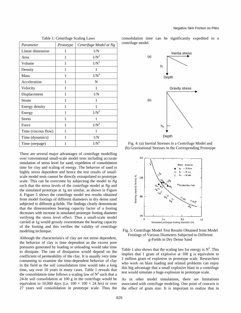
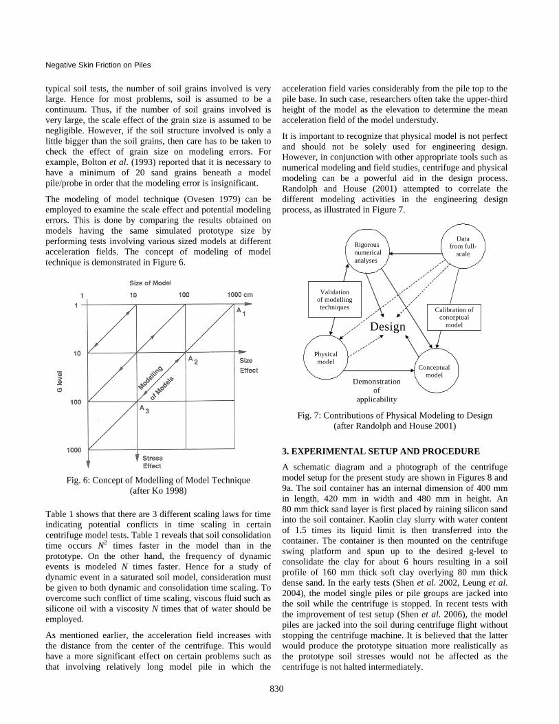
There are several major advantages of centrifuge modelling over conventional small-scale model tests including accurate simulation of stress level for sand, expedition of consolidation time for clay and scaling of energy. The behavior of sand is highly stress dependent and hence the test results of small-scale model tests cannot be directly extrapolated to prototype scale. This can be overcome by subjecting the model to Ng such that the stress levels of the centrifuge model at Ng and the simulated prototype at 1g are similar, as shown in Figure 4. Figure 5 shows the centrifuge model test results obtained from model footings of different diameters in dry dense sand subjected to different g-fields. The findings clearly demonstrate that the dimensionless bearing capacity factor of a footing decreases with increase in simulated prototype footing diameter verifying the stress level effect. Thus a small-scale model carried at 1g would grossly overestimate the bearing capacity of the footing and this verifies the validity of centrifuge modeling technique.
Although the characteristics of clay are not stress dependent, the behavior of clay is time dependent as the excess pore pressures generated by loading or unloading would take time to dissipate. The rate of dissipation would depend on the coefficient of permeability of the clay. It is usually very time consuming to examine the time-dependent behavior of clay in the field as the soil consolidation time would take a long time, say over 10 years in many cases. Table 1 reveals that the consolidation time follows a scaling law of N2 such that a 24-hr soil consolidation at 100 g in the centrifuge would be equivalent to 10,000 days (i.e. 100 × 100 × 24 hrs) or over 27 years soil consolidation in prototype scale. Thus the
consolidation time can be significantly expedited in a centrifuge model.
Fig. 4: (a) Inertial Stresses in a Centrifuge Model and
(b) Gravitational Stresses in the Corresponding Prototype
Fig. 5: Centrifuge Model Test Results Obtained from Model
Footings of Various Diameters Subjected to Different g-Fields in Dry Dense Sand
Table 1 also shows that the scaling law for energy is N3. This implies that 1 gram of explosive at 100 g is equivalent to 1 million gram of explosive in prototype scale. Researchers who work on blast loading and related problems can enjoy this big advantage that a small explosive blast in a centrifuge test would simulate a huge explosion in prototype scale.
As in other model simulations, there are limitations associated with centrifuge modeling. One point of concern is the effect of grain size. It is important to realize that in
Gravity stress
hp
Depth
Inertia stress
hm
Depth
(a)
(b)
Simulated prototype footing diameter (m)
Bea
ring
capa
city
fact
ory
Nγ
Negative Skin Friction on Piles
830
typical soil tests, the number of soil grains involved is very large. Hence for most problems, soil is assumed to be a continuum. Thus, if the number of soil grains involved is very large, the scale effect of the grain size is assumed to be negligible. However, if the soil structure involved is only a little bigger than the soil grains, then care has to be taken to check the effect of grain size on modeling errors. For example, Bolton et al. (1993) reported that it is necessary to have a minimum of 20 sand grains beneath a model pile/probe in order that the modeling error is insignificant.
The modeling of model technique (Ovesen 1979) can be employed to examine the scale effect and potential modeling errors. This is done by comparing the results obtained on models having the same simulated prototype size by performing tests involving various sized models at different acceleration fields. The concept of modeling of model technique is demonstrated in Figure 6.
Fig. 6: Concept of Modelling of Model Technique
(after Ko 1998)
Table 1 shows that there are 3 different scaling laws for time indicating potential conflicts in time scaling in certain centrifuge model tests. Table 1 reveals that soil consolidation time occurs N2 times faster in the model than in the prototype. On the other hand, the frequency of dynamic events is modeled N times faster. Hence for a study of dynamic event in a saturated soil model, consideration must be given to both dynamic and consolidation time scaling. To overcome such conflict of time scaling, viscous fluid such as silicone oil with a viscosity N times that of water should be employed.
As mentioned earlier, the acceleration field increases with the distance from the center of the centrifuge. This would have a more significant effect on certain problems such as that involving relatively long model pile in which the
acceleration field varies considerably from the pile top to the pile base. In such case, researchers often take the upper-third height of the model as the elevation to determine the mean acceleration field of the model understudy.
It is important to recognize that physical model is not perfect and should not be solely used for engineering design. However, in conjunction with other appropriate tools such as numerical modeling and field studies, centrifuge and physical modeling can be a powerful aid in the design process. Randolph and House (2001) attempted to correlate the different modeling activities in the engineering design process, as illustrated in Figure 7.
Design
Data from full-
scale
Conceptual model
Validation of modelling techniques
Physical model
Calibration of conceptual
model
Demonstration of
applicability
Rigorous numerical analyses
Fig. 7: Contributions of Physical Modeling to Design
(after Randolph and House 2001)
3. EXPERIMENTAL SETUP AND PROCEDURE
A schematic diagram and a photograph of the centrifuge model setup for the present study are shown in Figures 8 and 9a. The soil container has an internal dimension of 400 mm in length, 420 mm in width and 480 mm in height. An 80 mm thick sand layer is first placed by raining silicon sand into the soil container. Kaolin clay slurry with water content of 1.5 times its liquid limit is then transferred into the container. The container is then mounted on the centrifuge swing platform and spun up to the desired g-level to consolidate the clay for about 6 hours resulting in a soil profile of 160 mm thick soft clay overlying 80 mm thick dense sand. In the early tests (Shen et al. 2002, Leung et al. 2004), the model single piles or pile groups are jacked into the soil while the centrifuge is stopped. In recent tests with the improvement of test setup (Shen et al. 2006), the model piles are jacked into the soil during centrifuge flight without stopping the centrifuge machine. It is believed that the latter would produce the prototype situation more realistically as the prototype soil stresses would not be affected as the centrifuge is not halted intermediately.

Negative Skin Friction on Piles
831
405
120
7548
0
Vertical actuator Long LVDT
Sand hopper
container
Load cell
Guiding
Model pile
Clay
Sand
Model
pins
420
PPT2
PPT1
LVDT
Fig. 8: Centrifuge Model Setup (units in mm)
(after Leung et al. 2004)
The instrumented model pile is fabricated from a hollow cylindrical aluminium tube with a length of 278 mm, an external diameter of 12 mm and a wall thickness of 1 mm. Utmost efforts have been spared to instrument 9 levels of strain gauge stations with full-bridge configuration at appropriate elevations along the pile shaft. Calibration of the instrumented model pile shows that the response of the full-bridge strain gauge circuits are highly immune to thermal effects with typical calibration factor of about 0.1 kg/µε. The finished model pile is protected by a thin layer of epoxy resulting in a final outer diameter of 16 mm. The scaling relationship between prototype and model dimensions of the pile is N.
The completed model setup is then transported onto a swinging bucket of the centrifuge which is then spun up to the desired g-level. At this stage, the clay undergoes self-weight re-consolidation as it had swelled by a certain extent due to stress relief from high g to 1g during the centrifuge spun-down earlier. After re-consolidation of the clay has been completed, axial load is applied on the pile using the vertical load actuator prior to the placement of surcharge. The horizontal actuator is then activated. This enables the alignment of the holes at the base of the sand hopper and the underlying plate to coincide thus facilitating the sand from the hopper to fall onto the clay, see Figure 9b. The guiding flaps below the sand hopper are used to overcome the Coriolis Effect and direct the falling sand to form a
reasonably uniform surcharge on the soft clay surface. At this stage, the clay undergoes further consolidation settlement due to surcharge loading.
The model pile is connected to a load cell which in turn mounted to the piston of the vertical hydraulic actuator through a specially designed coupling connector. The coupling connector has a vertical slot with a length of about 7.6 mm. The piston of the vertical actuator engages the lower flange of the vertical slot when pushing the model pile downward during pile installation or when applying compression loading on the model pile. When the piston is withdrawn half-way within the vertical slot, it disengages from the pile for unloading.
(a) Front View
(b) Top View Showing Sand Hoppers
Fig. 9: Photographs of Centrifuge Model Setup
All the sensors in the model package are connected to the junction box and sent via the electrical slip ring the control

Negative Skin Friction on Piles
832
room where their signals are captured by a data acquisition system at frequent intervals. The readings of the strain gauges from the model piles are captured by a strain meter mounted onboard the centrifuge and connected to a control computer in the control room. The responses of the instrumented model piles as well as the pore water pressure and surface settlement of the soil during the entire test process are monitored by the data acquisition system in the centrifuge control room at regular intervals.
4. DIFFERENT SCENARIOS OF SOIL SETTLEMENT
In this section, the results of a centrifuge model test on an end bearing pile subject to soil settlement caused by different situations are presented. This centrifuge model test involves multiple sequential stages: soil self-weight consolidation; in-flight installation of pile; soil re-consolidation after pile installation; underground water drawdown; application of dead load; and in-flight application of surcharge. The three typical causes of soil settlement, namely re-consolidation of remoulded clay after pile driving, underground water drawdown as well as surcharge loading have been incorporated in the model test with application of load at selected stages.
0 50 100 150 200 250 300 350
Time after pile installation (days)
0
100
200
300
400
500
600
700
800
900
Incr
emen
t of a
xial
load
(kN
)
Soil reconsolidation Water drawdown
Level1
Level2
Level3
Level4
Level5
Level6
Level1
Level2
Level3
Level4
Level5
Level6
Level9Level8Level7
Fig. 10: Increase of Pile Axial Load during Soil
Reconsolidation (left portion) and Water Drawdown (right portion) (after Shen et al. 2006)
The development of incremental axial loads at various elevations along the pile shaft after pile installation is presented in the left portion of Figure 10. It can be seen that the pile axial load keeps on increasing after pile installation as the soil reconsolidates. The increase in negative skin friction along the pile shaft is shown in Figure 11 at selected times after pile installation. A maximum incremental negative skin friction of 620 kN is observed to develop near the pile tip at the end of soil re-consolidation. The neutral plane persists at the pile tip. The traditional α and β methods are used to back analyse the negative skin friction along the pile shaft at the end of reconsolidation. The derived α and β values are 0.95 and 0.24, respectively. It should be noted that
near the neutral plane, negative skin friction appears to be not fully mobilized since the soil settlement near the neutral plane is expected to be much smaller. As such, both the α and β methods tend to over-predict the maximum negative skin friction.
2120191817161514131211109876543210
Ele
vatio
n (m
)
0 100 200 300 400 500 600 700 800Incremental axial loads (kN)
Clay
Top sand layer
Rigid base
1248163264156
Days after installation
α curve β curve
Fig. 11: Pile Load Distribution Curves during Soil
Reconsolidation (after Shen et al. 2006)
50
40
30
20
10
0
-10
Set
tlem
ent (
mm
)
0 50 100 150 200 250 300 350Time after pile installation (day)
Soil reconsolidation Water drawdown
Temporary soil upheaval
pile settlementsoil settlement
Fig. 12: Soil Settlement during Soil Reconsolidation (left portion) and Water Drawdown (right portion)
(after Shen et al. 2006)
The development of negative skin friction during water drawdown stage is shown in the right portion of Figure 10. It is interesting to note that negative skin friction is observed to reduce abruptly upon the first instant of water drawdown and then slowly picks up again after about 4 days. This is against common wisdom that ground water drawdown would increase the vertical effective stress in the soil which would

Negative Skin Friction on Piles
833
incur further soil settlement and drag the pile down further. By examining the soil settlement plot shown in Figure 12, the soil is noted to settle during the soil re-consolidation stage after pile installation. Upon water drawdown, an appreciable amount of soil heave in the magnitude of about 2 mm is observed accompanying the process of water lowering, as illustrated in Figure 12. It is evident that this temporary heave of the soil results in the partial relief of negative skin friction on the pile caused by the earlier soil reconsolidation.
After the soil consolidation is completed, the vertical hydraulic actuator is activated to move down to engage the lower flange of the connector so as to apply additional 700 kN permanent dead load on the pile head. A number of existing field tests reveal that the application of dead load would reverse the negative skin friction developed prior to the application of the load such that the applied load is resisted by the reversed negative skin friction and never reaches the neutral plane of the pile (Fellenius 1972; Bozozuk 1981). However, contrary to what was observed by the above mentioned case histories, quite a large portion of the applied load is transferred to the neutral plane, contributing to the maximum axial load of on the pile as shown in Figure 13 (2nd curve from left) with negative skin friction still prevails along the pile shaft.
212019181716151413121110
9876543210
Ele
vatio
n (m
)
0 200 400 600 800 1000 1200 1400 1600 1800 2000 2200 2400Net downdrag loads (kN)
Clay
Top sand layer
Rigid baseBefore deadloadAfter deadloadhalf day after surchargeend of consolidation
β=0.24 using effective stress before surcharge
β=0.24 using effective stress after consolidation
α=1.9 using in-situ Cu
α=1 using Cu after consolidation
Fig. 13: Pile Load Transfer Curves Along an End-bearing
Pile (after Shen et al. 2006)
With the permanent dead load applied at the pile head, sand is discharged from the sand hoppers to apply 40 kPa surcharge onto the model ground surface. It is postulated that the rapid large immediate downward movement of the soil relative to the pile due to surcharge should have fully mobilised the negative skin friction on the pile. This postulation can be
verified by examining the load distribution along the pile shaft shown in Figure 13. It can be seen that the load along the pile shaft increases substantially along the entire length of pile shaft. By assuming that all this load increment occurs under undrained condition and the effective stresses in the soil remain the same as that prior to the application of the surcharge, a β value of 0.24 appear to fit the test data reasonably well, thus supporting the above postulation.
5. PILE SUBJECT TO SIMULTANEOUS NEGATIVE SKIN FRICTION AND VERTICAL LOAD
Piles are installed to support superstructure loads in the field and they are normally subject to axial loads and negative skin friction concurrently. The mechanism and performance of a pile subject to simultaneous negative skin friction and vertical load is reported in detail in Leung et al. (2004). The leftmost curve in Figure 14 shows that at the end of self-weight re-consolidation, the magnitude of negative skin friction is about 780 kN. After the clay has completely reconsolidated, an axial load of 4750 kN has gradually been applied to the pile.
24
20
16
12
8
4
0
-4
Ele
vatio
n (m
)
0 1000 2000 3000 4000 5000 6000 7000 8000Pile axial force (kN)
Sand
Clay
Clay surface after soil re-consolidationFinal clay surface after surcharge
Moving trend ofneutral plane
level 1level 2
level 1: level 2:
Load transfer from ground surface to neutral plane
Time after surcharge (months)
1
0.25
0
83 (end of test)
6
Fig. 14: Performance of Pile Subject to Simultaneous
Negative Skin Friction and Vertical Load (after Leung et al. 2004)
Figure 14 reveals that as the axial load increases, the ‘locked-in’ negative skin friction of 780 kN has gradually been overcome and the neutral plane gradually shifts upwards along the pile shaft. When the axial load reaches 2400 kN, which is about 3 times that of negative skin friction developed on the pile prior to the application of axial load, the ‘locked-in’ negative skin friction is completely

Negative Skin Friction on Piles
834
overcome. Upon further loading, the pile shaft moves further downwards relative to the surrounding soil and the shaft resistance acts upwards relative to the pile and thus the load transfer at the pile-soil interface becomes positive. This observation suggests that as long as the soil consolidation settlement has been completed, it is not necessary to consider negative skin friction in pile design if the applied load is considerably larger than the magnitude of negative skin friction.
After the relatively small magnitude of excess pore pressure generated during axial loading has fully dissipated, sand surcharge is placed in-flight to induce consolidation settlement of the clay. The right hand curves in Figure 14 show that upon application of surcharge, negative skin friction again develops along the upper pile shaft and increases with time as the clay consolidates. The neutral plane is observed to shift gradually downwards along the pile and finally stabilizes at about 12 m below the original ground surface. This observation is contrary to that observed for the case of pile subject to negative skin friction only in which the elevation of the neutral plane rapidly reaches its final position of around 90% depth of clay layer upon a relatively small magnitude of soil consolidation settlement.
24
20
16
12
8
4
0
-4
Ele
vatio
n (m
)
0 500 1000 1500 2000 2500 3000Pile axial force (kN)
clay/sand interfacefor Test N1
End-bearing levelfor Test N2
End of soil re-consolidation
Test N1
Test N2
Test N1
Test N2
End of consolidationafter surcharge
Fig. 15: Performance of End Bearing Pile versus Socketed
Pile (after Leung et al. 2004)
6. END BEARING VERSUS SOCKETED PILES
The above reported test results are obtained from end bearing piles in which the piles are resting on very hard stratum such as rock. Tests were also conducted on socketed piles in which the lower portion of the pile is socketed in stiff soil or weak rock. Figure 15 shows the comparison of pile axial load
profiles between the 2 pile tip conditions at the end of self-weight soil reconsolidation and soil consolidation due to surcharge. It is evident that negative skin friction developed along the upper portion of the pile shaft is similar for the two cases. However, the neutral plane for socketed pile (test N1) is located at around 90% depth of the clay stratum with a positive shaft friction below the plane. On the contrary, negative skin friction develops along the full length of the end-bearing pile (test N2) with the neutral plane located at the pile tip. This finding is consistent with that reported by Lee et al. (2002) who carried out a numerical finite element analysis on friction and end-bearing piles subject to negative skin friction.
7. PILE GROUPS
In an attempt to examine the effect of pile-soil-pile interaction upon negative skin friction developed in a pile group, two centrifuge model tests were conducted on pile groups in the present study. In one test, the pile group consists of 2 capped piles spaced at a centre-to-centre spacing of 3 pile diameters. In another test, the pile group consists of 4 capped piles arranged in a 2 × 2 pattern with the same centre-to-centre spacing of 3 pile diameters. In both tests, the piles are fixed to a rigid pile cap fabricated from brass of 10 mm thick. The pile cap would enforce a uniform settlement for the pile group. The soil condition in both tests is the same as that of single pile tests with 16 m soft clay overlying 8 m dense sand. The piles penetrated through the soft clay and embedded 2.5 m into the dense sand layer. The test procedure is essentially the same as single pile test to enable a fair comparison between the performance of a single pile and pile group. Owing to symmetrical nature of the piling layout, only one pile needs to be instrumented. No external axial load is applied in these pile group tests, and negative skin friction is induced by self-weight soil consolidation and subsequent surcharge loading.
The axial load transfer profile along the pile shaft at the end of self-weight consolidation and at the end of the test are plotted in Figure 16, together with those of single pile test. It can be seen that the pile axial force profiles along the pile shaft within the clay layer are very close to those obtained from the single pile test. This is attributed to the fact that full pile-soil slippage has occurred along the pile shaft due to large soil settlement. However, the maximum negative skin friction per pile for the pile group is marginally smaller than that of the single pile. This may be due to the pile-soil-pile interaction causing the reduction of effective soil vertical stress along the pile shaft of the individual pile among the pile group. On the other hand, the location of the neutral point is observed to be the same as that of single pile test.
An existing study is ongoing to evaluate the negative skin friction on larger size pile groups as illustrated. The preliminary results are presented here. Figure 17 shows the variation of measured negative skin friction versus size of

Negative Skin Friction on Piles
835
pile group from 2-pile to 16-pile groups. As established earlier, there is no significant reduction in the magnitude of negative skin friction if the size of pile group is less than 4 piles. However, the reduction in negative skin friction is noticeable when the number of piles in the group is 5 or more. It is interesting to note that the magnitude of negative skin friction on the corner pile is considerably larger than that on the inner piles. It is likely due to shielding effect as the inner piles are shielded and hence more protected against the settling soils. The distribution of magnitude of negative skin friction on different piles among a large pile group certainly deserves further studies. Overall there can be considerable reduction in negative skin friction for a large pile group as compared to that of a single pile. However, preliminary results illustrate that the reduction in negative skin friction decreases with increasing soil settlement. Further results will be reported in near future.
.
-4
0
4
8
12
16
20
24
0 300 600 900 1200 1500 1800Pile axial force (kN)
Dep
th b
elow
orig
inal
gro
und
surfa
ce (m
)
Series8single pile
2 pile group4 pile group
Series5Single pile2 pile group
4 pile group
Sand
Self-weight consolidation
At the end of test
Fig. 16: Comparison of Negative Skin Friction for Single
Pile, 2-pile and 2-pile Groups (after Shen et al. 2002)
0 2 4 6 8 10 12 14 16 18
Number of piles in group
0
200
400
600
800
1000
1200
1400
1600
Neg
ativ
e sk
in fr
ictio
n (k
N)
Corner piles
Inner piles
Fig. 17: Variation of Negative Skin Friction
with Size of Pile Group
8. CONCLUSION
At the National University of Singapore, extensive centrifuge model studies had been carried out to evaluate the performance of single piles and pile groups subject to simultaneous negative skin friction and vertical load. It is established that the magnitude of negative skin friction depends on the magnitude of soil movement rather than the mode of soil settlement. However, there may be differences in the temporary responses of the pile under different modes of soil settlement. As an example, water drawdown may cause a temporary upheaval of soil and hence temporary relief of negative skin friction immediate upon water drawdown but negative skin friction soon returns once the soil settles after a short time. The behaviour of an end bearing pile subject to negative skin friction can be quite different from that of a socketed pile due to the location of the neutral plane.
For piles subject to simultaneous negative skin friction and vertical load, a large applied vertical load can overcome the locked-in negative skin friction on a pile provided there is no further soil settlement under working condition. Hence negative skin friction needs not be considered in such case. However, it should be noted that negative skin friction will redevelop as long as there will be soil settlement under working condition. Hence the key is that the pile designers must make appropriate judgement on the ongoing soil settlement under pile working situations in considering negative skin friction on pile.
Large pile groups (pile number larger than 5) can be beneficial in the reduction of negative skin friction. However, preliminary studies reveal that the amount of reduction decreases with increasing soil settlement. In addition, the magnitude of negative skin friction along corner piles of a large pile group is considerably larger than that of the inner piles due to inner piles shielded from large soil settlement. The distribution of loads among piles in a large pile group and the reduction of negative skin friction of a large pile group against magnitude of soil settlement certainly deserve further studies.
ACKNOWLEDGEMENTS
The author wishes to acknowledge the great contribution of Dr R.F. Shen of NUS who had completed his Ph.D. study on the subject matter. The valuable inputs of Prof. Y.K. Chow of NUS are also greatly appreciated.
REFERENCES
Avgherinos, P.J. and Schofield, A.N. (1969). “Drawdown Failures of Centrifuged Models”, Proc 7th International Conference on Soil Mechanics and Foundation Engineering, Mexico City, Vol. 2, 497–505.
Bolton, M.D., Gui, M.W. and Phillips, R. (1993). “Review of Miniature Soil Probes for Model Tests”, Proc 13th Southeast Asian Geotechnical Conference, Singapore, 85–90.

Negative Skin Friction on Piles
836
Bozozuk, M. (1981). “Bearing Capacity of Pile Preloaded by Downdrag”, Proc. 10th International Conference of Soil Mechanics and Foundation Engineering, Vol. 2, 631~636.
Craig, W.H. (1995). “Geotechnical Centrifuge: Past Present and Future”, in Geotechnical Centrifuge Technology, Chapter 1, edited by R.N. Taylor, Blackie Academic and Professional, London, 1–18.
Fellenius, B.H. (1972). “Downdrag on Piles in Clay Due to Negative Skin Friction”, Canadian Geotechnical Journal, Vol. 9, No. 4, 323~327.
Fellenius, B.H. (1984). Negative Skin Friction and Settlement of Piles”, Proc. 2nd International Seminar on Pile Foundations, Nanyang Technological Institute, Singapore, p. 12.
Inoue, Y., Tamaoki, K. and Ogai, T. (1977). “Settlement of Building Due to Pile Downdrag”, Proc 9th International Conference of Soil Mechanics and Foundation Engineering, Tokyo, Japan, Vol. 1, 561~564.
Kimura, T. (1998). “Development of Geotechnical Centrifuges in Japan”, Proc. International Conference Centrifuge 98, Tokyo, Vol. 2, 945–954.
Ko, H.Y. (1988). “Summary of the State-of-the-Art in Centrifuge Model Testing”, in Centrifuges in Soil Mechanics, Edited by W.H. Craig, R.G. James and A.N. Schofield, Balkema.
Kog, Y.C. (1987). “A Case Study of Downdrag and Axial Load on Timber Piles in Layered Soil”, Proc. 5th Inter- national Geotechnical Seminar on Case Histories in Soft Clay, Nanyang Technological Institute, Singapore, 269~276.
Kog, Y.C. (1990). “Down-Drag and Axial Load on Piles”, Ground Engineering, April, 24~30.
Lee, C.J., Bolton, M.D. and Al-tabbaa, A. (2002). “Numerical Modelling of Group Effects on the Distribution of Dragloads in Pile Foundations”, Geotechnique, Vol. 52, No. 5, 325~335.
Lee, F.H., Tan, T.S., Leung, C.F., Yong, K.Y., Karunaratne, G.P. and Lee, S.L. (1991). “Development of Geotechnical Centrifuge Facility at National University of Singapore”, Proc. International Conference Centrifuge 91, Boulder, 11–17.
Leung, C.F., Lee, F.H. and Tan, T.S. (1991). “Principles and Applications of Geotechnical Centrifuge Model Testing”, Journal of Institution of Engineers Singapore, Vol. 31, No. 4, 39–45.
Leung, C.F., Liao, B.K., Chow, Y.K., Shen, R.F. and Kog, Y.C. (2004). “Behavior of Pile Subject to Negative Skin Friction and Axial Load”, Soils & Foundations, Vol. 44, No. 6, 17–26.
Mikasa, M., Takada, N. and Yamada, K. (1969). “Centrifuge Model Test of a Rockfill Dam”, Proc 7th International Conference on Soil Mechanics and Foundation Engineering, Mexico City, Vol. 2, 325–333.
Ovesen, N.K. (1979). “The Scaling Law Relationship”, Proc. 7th European Conference Soil Mechanics and Foundation Engineering, Brighton, Vol. 4, 319–323.
Randolph, M.F. and House, A.R. (2001). “The Complimentary Roles of Physical and Computational Modeling”, International Journal of Physical Modelling in Geotechnics, Vol. 1, No. 1, 1–8.
Shen, R.F, Leung C.F., Chow Y.K., Kog, Y.C. and Liao, B.K. (2002). “Negative Skin Friction on Piles”, Proc. International Conference on Physical Modelling in Geotechnics, Vol. 1, 673–678.
Shen, R.F., Leung, C.F. and Chow, Y.K. (2006). “Negative Skin Friction on End-Bearing Piles”, Proc. 6th International Conference in Physical Modelling and Geotechnics, Vol. 2, 875–880.
Taylor, R.N. (1995). Geotechnical Centrifuge Technology, Blackie Academic and Professional, London 1995.