nemo outdoor user manual
TRANSCRIPT

8/16/2019 Nemo Outdoor User Manual
http://slidepdf.com/reader/full/nemo-outdoor-user-manual 1/391
8/16/2019 Nemo Outdoor User Manual
http://slidepdf.com/reader/full/nemo-outdoor-user-manual 2/391
NEMO OUTDOOR USER MANUAL
Page 2
Copyright
The information contained in this document is confidential and no part of it may be copied orreproduced in any form without the written consent of Anite Network Testing. Additionally, thisdocument is not to be passed to or discussed with third parties without the prior written permission
of Anite Network Testing.
Anite’s products are subject to continual development and specifications may change. Users ofAnite’s products and documentation should exercise their own independent judgement to evaluatethe suitability of Anite’s products and documentation for their particular use. Anite does not acceptany liability arising from the application or use of the product or this documentation.
All reasonable care has been made to ensure that this document is accurate. If you have anycomments on this document, or would like details of any Anite products, services or equipment,please contact us through the Anite website.

8/16/2019 Nemo Outdoor User Manual
http://slidepdf.com/reader/full/nemo-outdoor-user-manual 3/391

8/16/2019 Nemo Outdoor User Manual
http://slidepdf.com/reader/full/nemo-outdoor-user-manual 4/391
NEMO OUTDOOR USER MANUAL
Page 4
4.5.2 Two data connections on one measurement server ............................... 39 4.6 General guidelines for drive testing ............................................................ 40
5 CONFIGURATION SETTINGS ............................................................................. 43
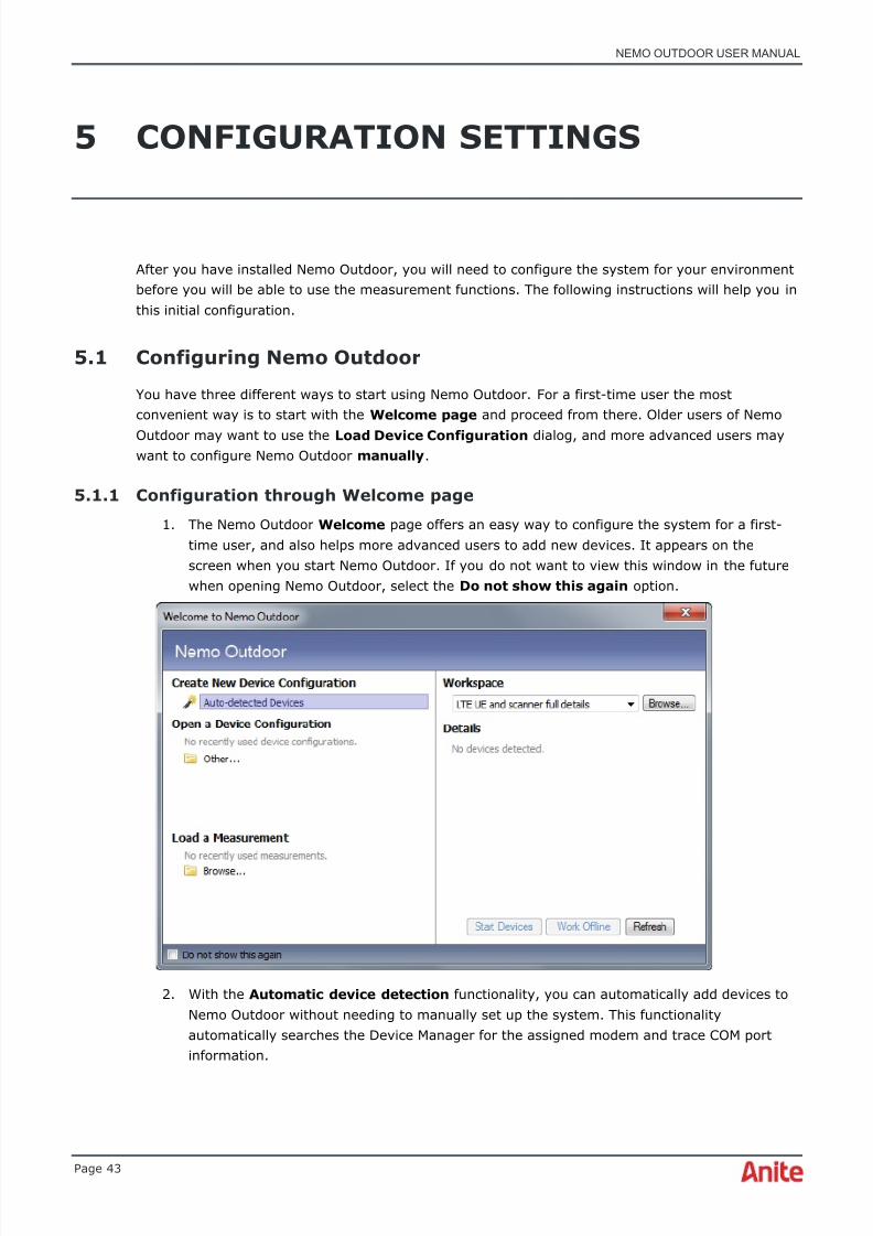
5.1 Configuring Nemo Outdoor ....................................................................... 43 5.1.1 Configuration through Welcome page ................................................. 43 5.1.2 Configuration through Load Device Configuration dialog ........................ 47 5.1.3 Configuring Nemo Outdoor manually .................................................. 49 5.1.4 Use case 1. Start measurements automatically upon device startup ........ 49
5.2 Configuring test mobiles ........................................................................... 50 5.3 Configuration Manager ............................................................................. 51
5.3.1 Handler information ......................................................................... 52 5.3.2 User interface ................................................................................. 52 5.3.3 Notifications ................................................................................... 64
5.3.4 Scripts ........................................................................................... 68 5.3.5 Base station files ............................................................................. 69 5.3.6 Device configurations ....................................................................... 69 5.3.7 Devices .......................................................................................... 70 5.3.8 View groups .................................................................................... 76
5.4 Measurement Properties dialog .................................................................. 76 5.4.1 Measurement Properties – General ..................................................... 77 5.4.2 Measurement Properties – Measurement ............................................. 78 5.4.3 Measurement Properties – Frequency scanning with mobiles .................. 82 5.4.4 Measurement Properties – Pilot scanning with mobiles .......................... 85
5.4.5 Measurement Properties – Frequency, pilot, and spectrum scanning withscanners .................................................................................................... 85 5.4.6 Measurement Properties - Script ........................................................ 86
6 DURING MEASUREMENTS ................................................................................. 87
6.1 Textual notes.......................................................................................... 87 6.2 Nemo Commander remote control option for Nemo Outdoor/ Invex ................ 88
6.2.1 Nemo Commander server options ...................................................... 89 6.2.2 Initial field unit configuration ............................................................. 90 6.2.3 Measurement workflow..................................................................... 90
6.2.4 Events reported by Nemo Outdoor/Nemo Invex to Nemo Commander ..... 91 6.3 Making scanning measurements ................................................................ 92
6.3.1 With a scanner ................................................................................ 92 6.3.2 With a mobile ................................................................................. 92
6.4 Making voice calls ................................................................................... 92 6.4.1 Voice Call Configuration .................................................................... 93 6.4.2 Voice Call Properties – TETRA ............................................................ 97 6.4.3 Push-to-Talk (PTT) testing ................................................................ 98
6.5 Voice quality measurements ................................................................... 101 6.6 Making video calls ................................................................................. 102
6.7 Data transfers ...................................................................................... 104 6.7.1 Configuring the data connection ...................................................... 105
8/16/2019 Nemo Outdoor User Manual
http://slidepdf.com/reader/full/nemo-outdoor-user-manual 5/391
NEMO OUTDOOR USER MANUAL
Page 5
6.7.2 Configuring the FTP protocol ........................................................... 110 6.7.3 Configuring the SFTP protocol ......................................................... 113 6.7.4 Configuring the HTTP(S) protocol ..................................................... 115 6.7.5 Configuring the (HTTP) browsing protocol ......................................... 118
6.7.6 Configuring the POP3 protocol ......................................................... 120 6.7.7 Configuring the SMTP protocol ......................................................... 121 6.7.8 Configuring the IMAP protocol ......................................................... 124 6.7.9 Configuring the WAP protocol .......................................................... 126 6.7.10 Configuring the streaming protocol .................................................. 128 6.7.11 Configuring the trace route protocol ................................................. 129 6.7.12 Making data transfers .................................................................... 131
6.8 Streaming video quality testing ............................................................... 132 6.8.1 PEVQ-S Properties dialog ................................................................ 134
6.9 VoIP calls ............................................................................................. 135
6.10 Application testing ................................................................................. 138 6.10.1 Facebook testing ........................................................................... 138 6.10.2 Twitter testing .............................................................................. 141 6.10.3 Instagram testing .......................................................................... 145 6.10.4 Dropbox testing ............................................................................ 148
6.11 SMS testing .......................................................................................... 151 6.11.1 SMS testing with CDMA terminals .................................................... 152
6.12 MMS testing ......................................................................................... 153 6.12.1 Packet session settings for MMS ...................................................... 153 6.12.2 MMS Editor dialog .......................................................................... 155
6.12.3 Making MMS measurements ............................................................ 155 6.12.4 MMS settings for Nokia N95, 6120, and 6121 .................................... 156
6.13 USSD testing ........................................................................................ 160 6.14 Start external application ....................................................................... 161 6.15 ICMP Ping ............................................................................................ 162 6.16 Indoor mode ........................................................................................ 164
6.16.1 Viewing indoor maps ...................................................................... 165 6.16.2 Floorplans and BTS files ................................................................. 167 6.16.3 Multiple routes and floorplans .......................................................... 169 6.16.4 Indoor route planning .................................................................... 170 6.16.5 iBwave maps ................................................................................ 171 6.16.6 DAS anomaly analysis .................................................................... 175 6.16.7 RF ingress analysis ........................................................................ 177 6.16.8 Indoor map popup menu ................................................................ 178
6.17 Measurement profiles ............................................................................ 186 6.18 IP packet capturing ............................................................................... 186 6.19 Making script files ................................................................................. 187
6.19.1 Script transfer stop commands ........................................................ 189 6.19.2 Add menu .................................................................................... 192 6.19.3 Running scripts ............................................................................. 203
6.20 Measurement lists ................................................................................. 204

8/16/2019 Nemo Outdoor User Manual
http://slidepdf.com/reader/full/nemo-outdoor-user-manual 6/391
NEMO OUTDOOR USER MANUAL
Page 6
6.20.1 Measurement areas ....................................................................... 208 6.21 Forcing functions ................................................................................... 209
6.21.1 Channel locking ............................................................................. 210 6.21.2 Band locking ................................................................................. 211
6.21.3 Network selection .......................................................................... 212 6.21.4 Handover control ........................................................................... 213 6.21.5 Cell barring................................................................................... 219 6.21.6 Set terminal radio on/off (airplane mode) ......................................... 219 6.21.7 AMR codec forcing ......................................................................... 220
6.22 Cell testing ........................................................................................... 220 6.23 Missing Neighbor Detection ..................................................................... 221
6.23.1 Missing neighbor detection with a mobile .......................................... 222 6.23.2 Missing neighbor detection with a scanner/scanner and mobile ............ 223
6.24 Pilot pollution analysis............................................................................ 225
6.24.1 UMTS Pilot Pollution Analysis on Mobile Phone ................................... 226 6.24.2 UMTS pilot pollution analysis based on scanner measurements ............ 228 6.24.3 CDMA/EVDO pilot pollution analysis - Mobile phones ........................... 228 6.24.4 CDMA/EVDO pilot pollution analysis - Scanners .................................. 229
6.25 GSM interference analysis ...................................................................... 229 6.26 Band scan ............................................................................................ 231 6.27 Timeslot testing .................................................................................... 234 6.28 Viewing graphs ..................................................................................... 236
6.28.1 Graph popup menu ........................................................................ 237 6.28.2 Zoom - Scatter graph ..................................................................... 240
6.28.3 Graph side panel - Layers ............................................................... 241 6.28.4 Graph side panel – Values and parameter ......................................... 248 6.28.5 Graph layer color configuration ........................................................ 250 6.28.6 Spectrum graphs ........................................................................... 254 6.28.7 Color grid graphs ........................................................................... 256 6.28.8 How to read MIMO parameters in a bar graph .................................... 256
6.29 Viewing grids ........................................................................................ 257 6.29.1 Find function in signaling grid based on decoded message ................... 258 6.29.2 Grid popup menu .......................................................................... 258
6.30 Viewing maps ....................................................................................... 282 6.30.1 Base stations on a map .................................................................. 284 6.30.2 MapX maps .................................................................................. 286 6.30.3 Route plans .................................................................................. 288 6.30.4 Map popup menu ........................................................................... 291 6.30.5 Color Set Editor ............................................................................. 315 6.30.6 Map example 1 ............................................................................. 318 6.30.7 Map example 2 ............................................................................. 319 6.30.8 Map example 3 ............................................................................. 320 6.30.9 Map example 4 ............................................................................. 321 6.30.10 Map example 5 ............................................................................. 322 6.30.11 Map Example 6 ............................................................................. 324

8/16/2019 Nemo Outdoor User Manual
http://slidepdf.com/reader/full/nemo-outdoor-user-manual 7/391
NEMO OUTDOOR USER MANUAL
Page 7
6.31 Export/import settings ........................................................................... 326 6.31.1 Export settings to file ..................................................................... 326 6.31.2 Export settings to FTP server .......................................................... 327 6.31.3 Import settings from file ................................................................. 328
6.31.4 Import settings from FTP server ...................................................... 329
7 ENDING MEASUREMENTS ............................................................................... 331
7.1 Measurement report .............................................................................. 332
8 MEASUREMENT RESULTS ............................................................................... 334
8.1 Analyzing measurement results ............................................................... 334 8.2 Playing back measurement files ............................................................... 334
8.2.1 Selecting playback files .................................................................. 334 8.2.2 During playback ............................................................................ 335 8.2.3 Viewing and moving markers .......................................................... 336 8.2.4 Closing playback files ..................................................................... 337
8.3 Uploading measurement files to server ..................................................... 337 8.3.1 FTP Options .................................................................................. 338 8.3.2 Nemo Xynergy Options ................................................................... 339
8.4 Exporting measurements ........................................................................ 340
9 USER INTERFACE .......................................................................................... 344
9.1 View groups ......................................................................................... 344 9.2 Menu bar ............................................................................................. 345 9.3 Toolbar ................................................................................................ 345 9.4 Status bar ............................................................................................ 345 9.5 Nemo Outdoor menus ............................................................................ 345
9.5.1 File menu ..................................................................................... 346 9.5.2 Edit menu .................................................................................... 347 9.5.3 View menu ................................................................................... 347 9.5.4 Measurement menu ....................................................................... 348 9.5.5 Remote menu ............................................................................... 349 9.5.6 Playback menu .............................................................................. 350 9.5.7 Data menu ................................................................................... 350
9.5.8 Window menu ............................................................................... 351 9.5.9 Help menu .................................................................................... 351
9.6 Parameters view ................................................................................... 352 9.6.1 Parameters view search functionality ................................................ 353
9.7 Customizing menus and toolbars ............................................................. 353 9.8 Nemo Outdoor windows ......................................................................... 356
9.8.1 Custom windows ........................................................................... 357 9.8.2 Devices view ................................................................................. 358 9.8.3 Device Status view ........................................................................ 360 9.8.4 Output window .............................................................................. 362
9.8.5 Script Status window ..................................................................... 362 9.8.6 Controlling windows ....................................................................... 362

8/16/2019 Nemo Outdoor User Manual
http://slidepdf.com/reader/full/nemo-outdoor-user-manual 8/391
NEMO OUTDOOR USER MANUAL
Page 8
10 TROUBLESHOOTING ...................................................................................... 364
10.1 Low throughput .................................................................................... 364 10.1.1 All Windows versions ..................................................................... 365
10.2 Device Status view ................................................................................ 368
10.3 Cannot add devices ............................................................................... 368 10.4 Required license option missing ............................................................... 369 10.5 Cannot make calls/packet transfers ......................................................... 369 10.6 Measurement file checksum notification .................................................... 369 10.7 Number of USB devices exceeded ............................................................ 369
11 NEMO OUTDOOR BUTTONS ............................................................................ 371
11.1 Toolbar buttons .................................................................................... 371 11.2 Dialog buttons ...................................................................................... 372 11.3 Graph toolbar buttons ............................................................................ 373
11.4 Map toolbar buttons .............................................................................. 374
12 SHORTCUT KEYS .......................................................................................... 376
13 NOTIFICATION SYMBOLS ............................................................................... 377
14 TECHNICAL SUPPORT .................................................................................... 380
14.1 User Club ............................................................................................. 380 14.2 Nemo Support Portal ............................................................................. 380 14.3 Phone and Email Support ....................................................................... 380
15 APPENDIX 1 ................................................................................................. 382 15.1 Making MapInfo ® raster maps ................................................................. 382
15.1.1 Registering a raster map with MapInfo ® SW ...................................... 382
16 APPENDIX 2 ................................................................................................. 384
16.1 CDMA settings and PRL editing in Nemo Outdoor ....................................... 384
17 END-USER LICENSE AGREEMENT .................................................................... 388

8/16/2019 Nemo Outdoor User Manual
http://slidepdf.com/reader/full/nemo-outdoor-user-manual 9/391
NEMO OUTDOOR USER MANUAL
Page 9
1 QUICK GUIDE
This quick guide will explain briefly how to set up the Nemo Outdoor measurement system and howto start the actual measurements. Check the cross-references for more detailed explanations onusing Nemo Outdoor.
1.1 Setting up the system
♦ Nemo Outdoor software license is tied to a HASP USB key and it is not possible to installNemo Outdoor without it. Software-based licenses are not available.
♦ Installing and running Nemo Outdoor requires administrator rights.
♦ Do not upgrade, root, or reflash your measurement terminal firmware. Doing so willcause the terminal to permanently lose its measurement capability!
1. Installing the software. Check the manual for hardware requirements if necessary (seeHardware and software requirements) . Run the Nemo Outdoor installation program NemoOutdoor.exe . The Nemo Outdoor SW and handlers are installed in the same setup.
2. When the installation is finished, restart the computer.
3. The measurement mobiles , GPS receiver, and scanner are connected to thecomputer’s USB ports.
4. If you are making data measurements, you need to configure the measurement devices andinstall drivers. Follow the instructions in the Device Configuration Guide provided in theNemo Outdoor package.
5. On the Welcome page, the Load a Measurement tool enables you to open a previouslyviewed measurement with the attached devices for playback. In the Open a DeviceConfiguration tool you can select saved device configurations, and start the devices inonline mode, or decide to work offline first and connect and start them later by clicking thework offline button in Nemo Outdoor. In addition, the Automatic device detectionfunctionality in the Create New Device Configuration tool automatically detects devices
connected to the computer and assigns the appropriate, previously created COM ports tothem.
6. To view the Load Device Configuration dialog, click the Other.. button in the Open aDevice Configuration field in the Welcome to Nemo Outdoor dialog (see Configurationthrough Load Device Configuration dialog) .

8/16/2019 Nemo Outdoor User Manual
http://slidepdf.com/reader/full/nemo-outdoor-user-manual 10/391
NEMO OUTDOOR USER MANUAL
Page 10
7. If you have used Nemo Outdoor before and would like to start in online mode, select apremade device configuration and click Start Devices . All the devices included in thedevice configuration file will be activated and you are ready to start measurements. If youprefer setting up the measurement configuration offline, that is, without connecting andstarting the measurement devices, select a pre-made device configuration and click theWork Offline button. You can change the measurement configurations in the offline modeand activate the device later. When you want to activate the devices, connect the devices tothe measurement system and click the work offline button in the Nemo Outdoor toolbar.
8. If you want to configure Nemo Outdoor manually, close the Welcome page or Load DeviceConfiguration dialog when you start Nemo Outdoor. You can go to File | OpenMeasurement , and select a saved measurement for playback, or you can open a saveddevice configuration in File | Open Device Configuration and start a measurement inonline of offline mode. Alternatively, you can go to Measurement | Add New Device ,select a device and configure it for measurements. You can also do this from theconfiguration manager (Ctrl+M) (see step 9). In addition, you can also use the Autodetect devices functionality by going to Measurement | Autodetect Devices , whichautomatically detects a previously added device and its assigned COM ports.
9. Open the Configuration Manager dialog (Ctrl+M) to add measurement devices manually.Select the Device item and click the Add button . Select the device type (phone, scanner,GPS) that you want to add and select the device model from the list. Click Next . In theDevice Configuration dialog, select the correct COM ports and click OK .
10. If you are using a GPS receiver, you will also need a map. Use the Windows® Explorer tocopy all the required map files to the maps folder, for example, C:\Nemo Tools\maps.Define the default map file and map folder as follows: open the Configuration Manager
dialog, double-click the User Interface item and select the Paths tab. In the Map field,browse the folder where map files are stored. In the Default map field, browse the defaultmap file (see User Interface Properties – Paths) .
11. If you have base station files (.nbf or .csv), copy them to the BTS files folder, for example,C:\Nemo Tools\BTS files. When you want to view a BTS file on a map, open theMeasurement Properties dialog for the measurement mobile used, and browse a file inthe BTS File field. Click OK . Open a map through the Data menu and the BTS icons shouldappear on the map.
1.2 Data measurements
♦ A PPP compatible server is required for CS data testing. Settings related to the server(number, username, and password) are operator-specific.
♦ Follow the instructions in the Device Configuration Guide to configure the measurementmobile.
Setting up data measurements:
1. Configure the measurement device in the Device Configuration dialog (see Deviceconfiguration for mobiles and modems) . Define the Trace and Modem Ports and select adata connection.
2. Open the Measurement Properties, Measurement dialog (see Measurement Properties –Measurement) . Please note that the selection is device-specific.

8/16/2019 Nemo Outdoor User Manual
http://slidepdf.com/reader/full/nemo-outdoor-user-manual 11/391
NEMO OUTDOOR USER MANUAL
Page 11
3. For circuit-switched data measurements, double-click the Circuit-Switched Data Call itemto define Data Call Properties. For packet-switched data calls, double-click the PacketSession item to define Packet session settings.
4. Select and configure a data protocol in by double-clicking the item under Supported DataProtocols .
5. To set up ICMP Ping measurements (can be performed simultaneously with the datameasurements), double-click the ICMP Ping field and define the Ping Settings (see ICMPPing) .
6. To set up SMS measurements (can be performed simultaneously with the datameasurements), double-click the Short Messaging Service field and define the SMS TestingSettings (see SMS testing) .
7. To set up MMS measurements (can be performed simultaneously with the data
measurements), double-click the Multimedia Messaging Service field and define theMMS Settings (see MMS testing) .
8. To set up USSD measurements (can be performed simultaneously with datameasurements), double-click the USSD Message field and define the USSD MessageSettings (see USSD testing) .
9. Click OK . You can now start data measurements.
8/16/2019 Nemo Outdoor User Manual
http://slidepdf.com/reader/full/nemo-outdoor-user-manual 12/391
NEMO OUTDOOR USER MANUAL
Page 12
1.3 Using Nemo Outdoor
When a green light is blinking in the Device Status window, the device is connected properly and isready for measurements.
1. First, open some measurement windows through the Data menu for monitoring themeasurement. Alternatively you can open a workspace ( File | Open Workspace ) thatcontains some predefined views (graphs, grids, maps, etc.).
2. You can use Scripts (see Scripts) to generate a sequence of actions that Nemo Outdoor willexecute automatically. Click the Device script settings button in the Devices view . Select an existing script in the Script File field or create a new one by clicking the ScriptEditor button.
3. If you want to be notified about certain events during the measurement, use theNotifications function (see Notifications) . Click the Device notification settings button
in the Devices view to access the Notifications dialog.
4. Run a script by clicking the Start/Stop Scripts button . Nemo Outdoor will start therecording automatically. To stop running the script, click the button again. To finish both therecording and the script, click the Stop button .
5. To perform measurements manually, select the appropriate actions, such as, start voice callor send MMS message, from the Measurement control menu.
6. Stop the recording by clicking the Stop button . Nemo Outdoor has recorded ameasurement file of the performed test calls/scan on the computer’s hard disk. You canplayback the measurement file by clicking the Playback button in the Report dialog. Clickthe Rename button to change the file name.
7. Click the Start Playback button to playback a file. During playback use the Pause button to freeze the playback and observe the different measurement windows for thatparticular point in time.
1.3.1 Using Nemo Outdoor with command line options
Outdoor supports the following command line options. These command lines will enable the user toenter a certain profile in Nemo Outdoor. You can enter the command lines either with CommandPrompt through Start | Run | cmd , or you can create a shortcut to Nemo Outdoor on the desktopand enter the command line to the shortcut’s Properties | Shortcut |Target field.
• /W <workspace> will directly open the specified workspace in Nemo Outdoor
• /H <hw config> will directly open the given hardware configuration in Nemo Outdoor
• /M SIMPLE will open Nemo Outdoor in limited mode, in which the user is not able to saveany changes made to the hardware configuration or workspace
• /DEBUGBIN will start debug logging
For example, the command line below will start Nemo Outdoor, load the test.worx workspace,N95.hwcx hardware configuration, and prevent any changes possibly made to them from takingeffect.
• Outdoor /W test.worx /H N95.hwcx /M SIMPLE
8/16/2019 Nemo Outdoor User Manual
http://slidepdf.com/reader/full/nemo-outdoor-user-manual 13/391
NEMO OUTDOOR USER MANUAL
Page 13
2 BEFORE YOU BEGIN
This manual explains how to set up and operate the Nemo Outdoor Air Interface Measurement ToolSoftware developed by Anite.
Nemo Outdoor is a portable engineering tool for measuring and monitoring the air interface ofdigital networks. The supported network standards are:
cdmaOne 450, 800,1900 MHzCDMA20001xEVDO
AMPSDVB-HEGPRSGSM 850, 900, 1800, 1900 MHzGPRSHSDPAHSUPAHSPA+LTETD-SCDMATETRA
iDENUMTS (FDD mode)WiMAX
Nemo Outdoor is an effective tool for tracing digital networks. Nemo Outdoor collects measurementresults and geographical coordinates (when used with a GPS receiver) and stores them on a harddisk. Measurement results provide useful information for network optimization, verification, andmaintenance purposes. Results can be efficiently and easily viewed with the Nemo analysis toolNemo Analyze.
Nemo Outdoor uses licensed technology from various manufacturers. For a complete list ofsupported devices, see the Nemo Outdoor product description and data sheet.
8/16/2019 Nemo Outdoor User Manual
http://slidepdf.com/reader/full/nemo-outdoor-user-manual 14/391
NEMO OUTDOOR USER MANUAL
Page 14
2.1 Licensing
Nemo Outdoor software license is tied to a HASP USB key and it is not possible to install NemoOutdoor without it. Software-based licenses are not available.
A new license type and dongle HW was introduced with Nemo Outdoor 7.5.0. All fielded dongle keysand licenses must be migrated to a new dongle when used with Nemo Outdoor version 7.5.0 orhigher.
To make the migration easier for our customers, Anite Network Testing has developed a user-friendly dongle migration tool that is capable of performing the migration. The old dongle key andthe new dongle key must be connected to the PC where the migration tool is installed. The tooldeactivates the old dongle and activates and registers the new one.
♦ The new USB dongle key must be available before updating Nemo Outdoor application toversion 7.5.0 or higher. Nemo Outdoor version 7.5.0 or higher is not backwards compatible withthe old l icense dongles.
♦ The computer used for the dongle migration must be connected to the internet.
♦ If the old dongle key contains both Nemo Outdoor and Nemo Analyze licenses, please do notrun the migration tool. Instead, contact [email protected].
♦ Before running the migration tool, please check t he TS Expiration date for the old dongle keyfrom t he Nemo Outdoor Help menu (About | License Information). If your technical supportagreement has expired, do not r un the migration tool. Migration can be done only wi th donglekeys that have a valid TS agreement. If your TS agreement has expired, please cont act Ani teNetwork Testing, [email protected].
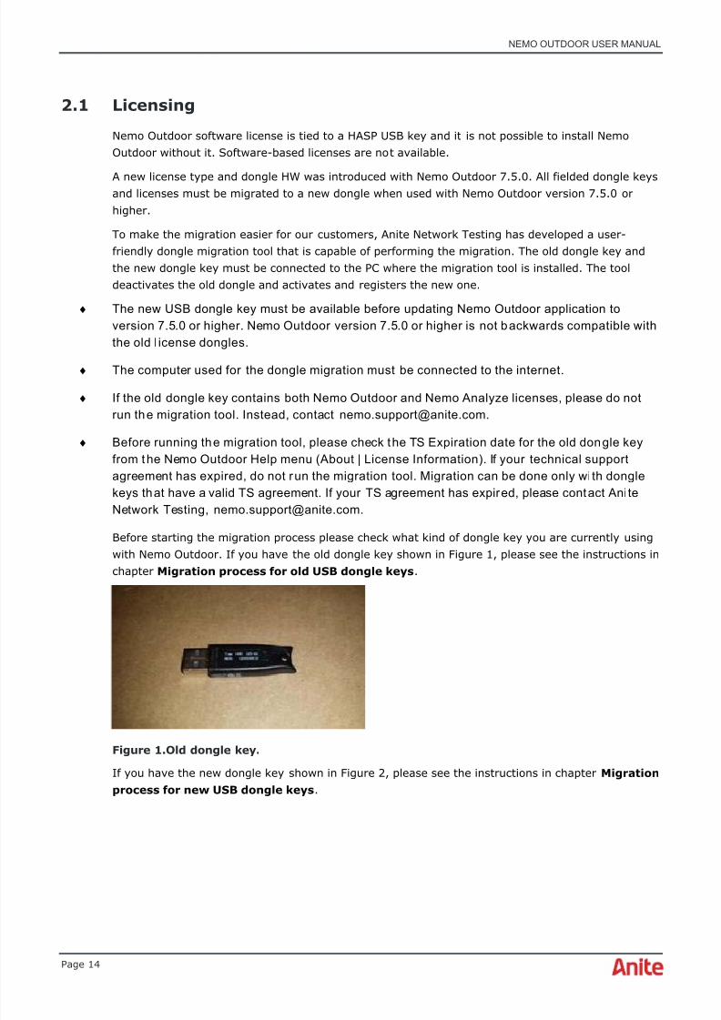
Before starting the migration process please check what kind of dongle key you are currently usingwith Nemo Outdoor. If you have the old dongle key shown in Figure 1, please see the instructions inchapter Migration process for old USB dongle keys .
Figure 1.Old dongle key.
If you have the new dongle key shown in Figure 2, please see the instructions in chapter Migrationprocess for new USB dongle keys .

8/16/2019 Nemo Outdoor User Manual
http://slidepdf.com/reader/full/nemo-outdoor-user-manual 15/391
NEMO OUTDOOR USER MANUAL
Page 15
Figure 2. New dongle key.
2.1.1 Migration process for old USB dongle keys
1. Anite sends an empty dongle (without a product license) automatically to all customers with a validTS agreement. The new dongle will be sent to a separately agreed customer address. In case you
have not been contacted by Anite regarding the dongle migration, please [email protected].
2. After receiving the empty dongle, download and install the migration tool from:
• www.nemo.fi/tools/migrationtool.zip
3. Extract the migration tool zip-file on the computer that has Nemo Outdoor or Nemo Analyzeinstalled.
4. Plug in both the old and the new dongle key to the computer where you installed the migration tool.Both dongles MUST be plugged in simultaneously.
♦ Do not unplug the dongle keys during the migration process. This may permanently damagethe keys.
5. Run the DriverlessMigrationClient.exe file to start the migration tool.
8/16/2019 Nemo Outdoor User Manual
http://slidepdf.com/reader/full/nemo-outdoor-user-manual 16/391
NEMO OUTDOOR USER MANUAL
Page 16
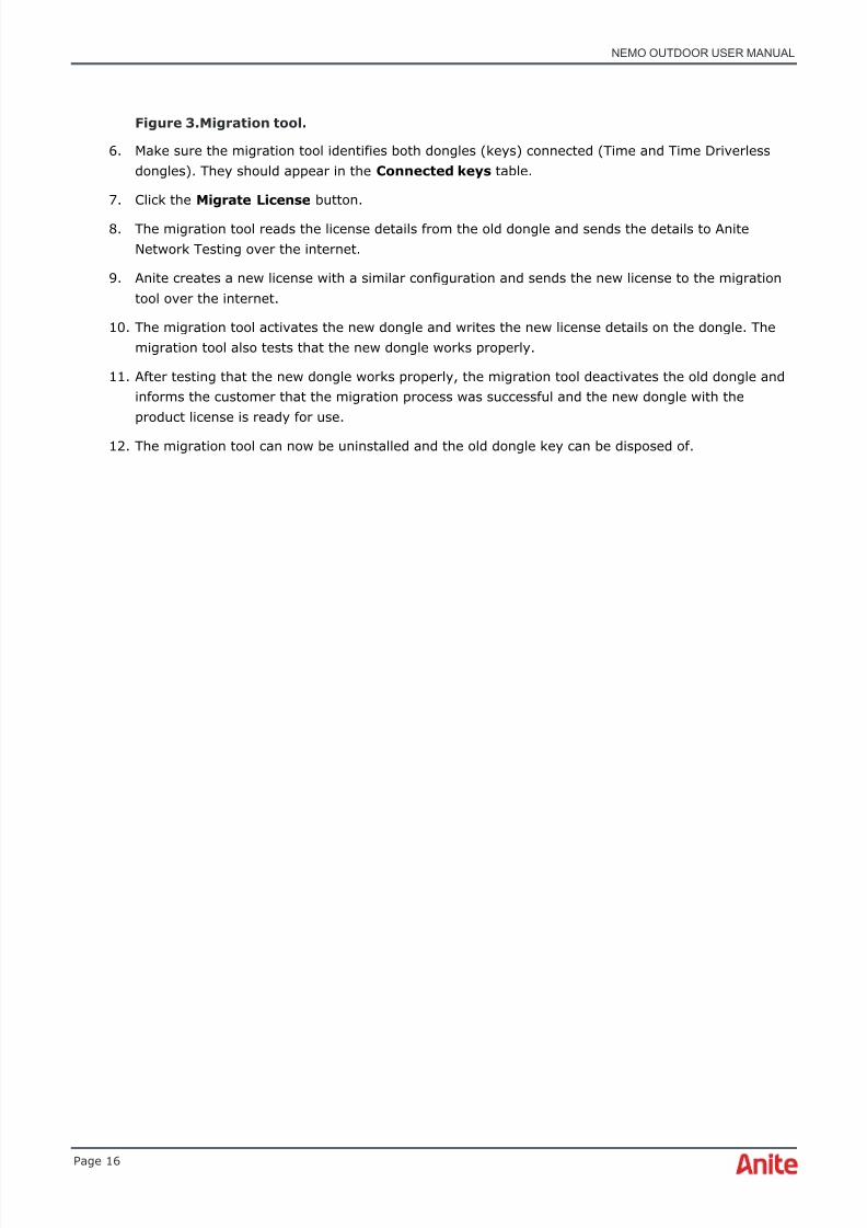
Figure 3.Migration tool.
6. Make sure the migration tool identifies both dongles (keys) connected (Time and Time Driverlessdongles). They should appear in the Connected keys table.
7. Click the Migrate License button.
8. The migration tool reads the license details from the old dongle and sends the details to AniteNetwork Testing over the internet.
9. Anite creates a new license with a similar configuration and sends the new license to the migrationtool over the internet.
10. The migration tool activates the new dongle and writes the new license details on the dongle. Themigration tool also tests that the new dongle works properly.
11. After testing that the new dongle works properly, the migration tool deactivates the old dongle andinforms the customer that the migration process was successful and the new dongle with theproduct license is ready for use.
12. The migration tool can now be uninstalled and the old dongle key can be disposed of.

8/16/2019 Nemo Outdoor User Manual
http://slidepdf.com/reader/full/nemo-outdoor-user-manual 17/391
NEMO OUTDOOR USER MANUAL
Page 17
2.1.2 Migration process for new USB dongle keys
1. Download and install the migration tool from:
• www.nemo.fi/tools/migrationtool.zip
2. Extract the migration tool zip-file on the computer that has Nemo Outdoor or Nemo Analyzeinstalled.
3. Plug in the dongle key to the computer where you installed the migration tool.
♦ Do not unplug the dongle key during the migration process. This may permanently damage thekey.
4. Run the DriverlessMigrationClient.exe file to start the migration tool.
Figure 4. Migration tool.
5. Click the Migrate License button.
6. The migration tool reads the license details from the dongle and sends the details to Anite NetworkTesting over the internet.
7. Anite creates a new license with a similar configuration and sends the new license to the migrationtool over the internet.
8. The migration tool writes the new license details on the dongle. The migration tool also tests thatthe dongle works properly.
9. After testing that the dongle works properly, the migration tool informs the customer that themigration process was successful and the dongle with the new product license is ready for use.
10. The migration tool can now be uninstalled.
8/16/2019 Nemo Outdoor User Manual
http://slidepdf.com/reader/full/nemo-outdoor-user-manual 18/391
NEMO OUTDOOR USER MANUAL
Page 18
2.1.3 Technical support expiration
The USB dongle keys used with Nemo Outdoor include a compulsory technical support andmaintenance agreement option. The technical support expiration date defines the date theagreement ends. After this date it is not possible to start the new version of the Nemo Outdoor
application. Example: A customer has purchased Nemo Outdoor version 7.50 with a 1-yeartechnical support maintenance agreement in April 2015. The customer is entitled for free updatesuntil April 2016. Nemo Outdoor versions released after April 2016 cannot be used with the USB keywithout renewing the technical support & maintenance agreement. After the technical support &maintenance agreement is renewed, the key can be updated remotely and the customer can updatethe application to the latest version.
2.2 Important
♦ Installing and running Nemo Outdoor requires administrator rights.
♦ Do not upgrade, root, or reflash your measurement terminal firmware. Doing so willcause the terminal to permanently lose its measurement capability!
The Nemo Outdoor user must be appropriately trained and should be familiar with the signalingbehind wireless technologies.
The Qualcomm handlers enables the use of Qualcomm CDMA2000, MSM6500, MSM6800, TM6200,TM6250, TM6275, TM6275US, TM7200, and TM8200 chipset-based terminals that have not beenverified by Anite. These terminals can be used with Nemo Outdoor but Anite does not guaranteethat the terminals will work flawlessly. Please check the Nemo Outdoor product description for a listof measurement terminals verified and approved by Anite.
Do not use the Nemo Outdoor test mobile’s keypad to make or answer calls when the NemoOutdoor system is running.
With Samsung terminals the key tone volume should be turned off. Otherwise, the mobile can dial awrong number.
With Nokia GSM, GPRS, and EDGE terminals the test display (Net Monitor) must not be activated.
In voice quality measurements the volume of the mobile headset must be adjusted to correctlevels. Please refer to the Nemo Voice Quality Guide document.
Do not place stickers containing metal on the mobile because it may lower the transmission powerof the mobile.
After the measurements have been completed and it is desired to take the Nemo Outdoor testmobile into normal use, it must be powered off and on again to deselect/deactivate the NemoOutdoor triggered events in the mobile.
Use only the supplied connecting cable, included with the Nemo Outdoor, for connecting the NemoOutdoor test devices to the computer’s USB port.
When using the Nemo Outdoor test mobile for measurement use, the battery operation time isreduced from normal use. The best operation times will be achieved when the batteries areregularly charged and discharged as instructed in the mobile user manual.
8/16/2019 Nemo Outdoor User Manual
http://slidepdf.com/reader/full/nemo-outdoor-user-manual 19/391
NEMO OUTDOOR USER MANUAL
Page 19
2.2.1 Local laws and regulations
Note that the local laws and/or regulations may set limitations, restrictions or other obligations onthe use of the Nemo Outdoor and/or the test devices. Observe the laws and regulations of thecountry (as well as of any other relevant jurisdiction) where the Nemo Outdoor and/or test device is
used. Anite assumes no responsibility or liability arising from the failure to comply with the locallaws and/or regulations.
2.2.2 Nemo Outdoor laptop settings
The laptops used for running Nemo Outdoor need to be set up before measurements. Below aredescribed the most important settings that may have an effect on the measurement results.
2.2.2.1 Power options
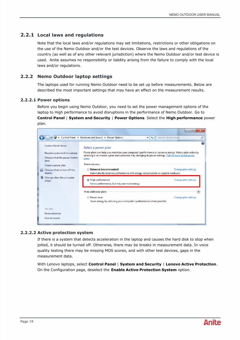
Before you begin using Nemo Outdoor, you need to set the power management options of thelaptop to High performance to avoid disruptions in the performance of Nemo Outdoor. Go to
Control Panel | System and Security | Power Options . Select the High performance powerplan.
2.2.2.2 Active protection system
If there is a system that detects acceleration in the laptop and causes the hard disk to stop when jolted, it should be turned off. Otherwise, there may be breaks in measurement data. In voicequality testing there may be missing MOS scores, and with other test devices, gaps in themeasurement data.
With Lenovo laptops, select Control Panel | System and Security | Lenovo Active Protection .On the Configuration page, deselect the Enable Active Protection System option.

8/16/2019 Nemo Outdoor User Manual
http://slidepdf.com/reader/full/nemo-outdoor-user-manual 20/391
NEMO OUTDOOR USER MANUAL
Page 20
2.2.2.3 USB hub properties
Also, check the generic USB hub properties. Go to Device Manager, expand the Universal SerialBus controllers item, right-click the Generic USB Hub item and select Properties . Open thePower Management tab and check that the Allow the computer to turn off this device tosave power option is deselected. Repeat this for all the Generic USB Hub items.
2.2.3 Traffic safety
Do not operate Nemo Outdoor and drive (or walk) at the same time. Remember, traffic safetycomes first.
Note that in some countries it is illegal to drive a car and operate a computer at the same time.Please observe the legislation of the country where the measurements are performed. Aniteassumes no responsibility or liability arising from the failure to comply with local legislation.
Always observe the local speed limits and traffic regulations when conducting drive testing.
8/16/2019 Nemo Outdoor User Manual
http://slidepdf.com/reader/full/nemo-outdoor-user-manual 21/391
NEMO OUTDOOR USER MANUAL
Page 21
2.2.4 Operating environment
Do not operate Nemo Outdoor without reading the User Manual, including its warnings, for thedevices used by Nemo Outdoor.
Always stop using Nemo Outdoor and switch off the Nemo Outdoor test device(s) when it isforbidden to use radio equipment or when it may cause interference or danger.
Do not use the Nemo Outdoor test device(s) in a hospital. It may interfere with nearby electronicdevices.
Never use Nemo Outdoor in an aircraft. The use of mobiles in an aircraft may be dangerous.
Observe restrictions on the use of radio equipment in gas stations, fuel depots, chemical plants, orsites where blasting operations are in progress.

8/16/2019 Nemo Outdoor User Manual
http://slidepdf.com/reader/full/nemo-outdoor-user-manual 22/391
NEMO OUTDOOR USER MANUAL
Page 22
3 NEMO OUTDOOR SYSTEM OVERVIEW
3.1 Voice testing
The voice testing environment consists of Nemo Outdoor compatible mobiles and a PC (userprovided or, optionally, provided by Anite with all the software installed). The package also includesthe necessary connecting cables, serial or USB port adapters, a GPS receiver, and fast frequencyscanners if applicable. Also the Nemo Voice Quality option is available.
3.2 Circuit-switched data testing
The circuit-switched (CS) data testing environment consists of three parts: a measurement unit(Nemo Outdoor), an application server, and a data server. The data server is used to establish adata connection between the measurement unit and the application server. Nemo Data Test Servercan be used as the application server. It is a Linux-based administration-free server having up tofour public IP addresses and it can serve multiple simultaneous TCP/IP connections from testterminals. Nemo Data Test Server supports FTP, SFTP, HTTP, POP3, SMTP, IPerf for UDP/TCP, Ping,Trace route testing and RTSP (video streaming). CS data testing is possible on all cellulartechnologies that support circuit-switched data.
The data measurement system has two modes: Send and Receive. In the Send mode, the
measurement unit sends data packets to the application server; in the Receive mode vice versa. Ifyou are using a FTP server, the measurement unit uploads (Send mode) or downloads (Receivemode) test files to or from the FTP server. If you are using an HTTP server, the measurement unitcan only receive files.
The user can define the number of timeslots and the coding schemes, which in turn define thedesired transfer rate. During the measurement, the user will be able to monitor data throughputsand error rates on different network layers, as well as certain parameters, such as coding schemeand number of timeslots.
3.3 Packet-switched data testing
The packet-switched (PS) data testing environments consist of two ends: the measurement unitand an application server. Nemo Data Test Server can be used as the application server. It is aLinux-based administration-free server having up to four public IP addresses and it can servemultiple simultaneous TCP/IP connections from test terminals. Nemo Data Test Server supportsFTP, SFTP, HTTP, POP3, SMTP, IPerf for UDP/TCP, Ping, Trace route testing, and RTSP (videostreaming). PS data testing is possible on all cellular technologies that support packet-switcheddata.
The data measurement system has two modes: Send and Receive. In the Send mode, themeasurement unit sends data packets to the application server; in the Receive mode vice versa. Ifyou are using an FTP server, the measurement unit uploads (Send mode) or downloads (Receivemode) test files to or from the FTP server. If you are using an HTTP server, the measurement unitcan only receive files.
8/16/2019 Nemo Outdoor User Manual
http://slidepdf.com/reader/full/nemo-outdoor-user-manual 23/391
NEMO OUTDOOR USER MANUAL
Page 23
During the measurement, the user will be able to monitor data throughputs and error rates ondifferent network layers, as well as certain parameters such as coding scheme and number oftimeslots.
3.4 Nemo Media RouterNemo Media Router (NMR) is Anite’s proprietary communications interface and applicationdeveloped for Android-based smartphones. With the NMR interface, smartphones communicate withPC-based applications, such as, Nemo Outdoor and Nemo Invex, enabling voice quality(PESQ/POLQA) measurements and data transfers on smartphones without any additional hardware.
When performing voice quality measurements with NMR, the smartphone records the receivedsample audio files and transfers audio files via the NMR interface to the test computer in real time.The computer calculates the PESQ/POLQA MOS scores and the values are written in the NemoOutdoor log file. Eight phones can be connected to one CPU simultaneously.
Also data transfers can be made using Nemo Media Router installed on the smartphone.♦ NMR versions 1.0 and 1.1 are not supported with Nemo Outdoor version 7.3.0.x.
Customers using Nemo Media Router 1.0 or 1.1 should not update Nemo Outdoor to thelatest version before updating the Nemo Media Router application on the test handsets.Nemo Media Router application and update instructions are available from the Nemo UserClub http://nemouserclub.anite.com.
♦ NMR Voice Quality Testing Option can be fetched from NMR license server automaticallyfor all the currently fielded units by launching the Nemo Media Router 2.00 application onthe phone after installation.
3.4.1 Installing Nemo Media RouterThis chapter will describe the steps for setting up and configuring Nemo Media Router. Handsetsordered with Nemo Media Route come preinstalled from Anite. If you wish to use your existingNemo Outdoor test terminals, please install the Nemo Media Router first. Please check the NemoMedia Router data sheet for a list of supported devices.
Requirements:
• Nemo Handy firmware
1. Next install the Nemo Media Router on the mobile (if not preinstalled by Anite). Connect thedevice to your laptop with a USB cable. Copy the NemoMediaRouter.apk file on your devicein the Nemo folder.
8/16/2019 Nemo Outdoor User Manual
http://slidepdf.com/reader/full/nemo-outdoor-user-manual 24/391
NEMO OUTDOOR USER MANUAL
Page 24
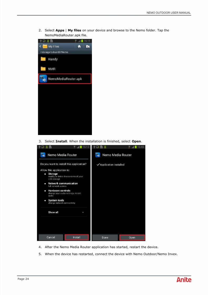
2. Select Apps | My files on your device and browse to the Nemo folder. Tap theNemoMediaRouter.apk file.
3. Select Install . When the installation is finished, select Open .
4. After the Nemo Media Router application has started, restart the device.
5. When the device has restarted, connect the device with Nemo Outdoor/Nemo Invex.
8/16/2019 Nemo Outdoor User Manual
http://slidepdf.com/reader/full/nemo-outdoor-user-manual 25/391
NEMO OUTDOOR USER MANUAL
Page 25
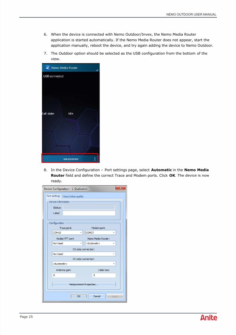
6. When the device is connected with Nemo Outdoor/Invex, the Nemo Media Routerapplication is started automatically. If the Nemo Media Router does not appear, start theapplication manually, reboot the device, and try again adding the device to Nemo Outdoor.
7. The Outdoor option should be selected as the USB configuration from the bottom of the
view.
8. In the Device Configuration – Port settings page, select Automatic in the Nemo Media
Router field and define the correct Trace and Modem ports. Click OK . The device is nowready.
8/16/2019 Nemo Outdoor User Manual
http://slidepdf.com/reader/full/nemo-outdoor-user-manual 26/391
NEMO OUTDOOR USER MANUAL
Page 26
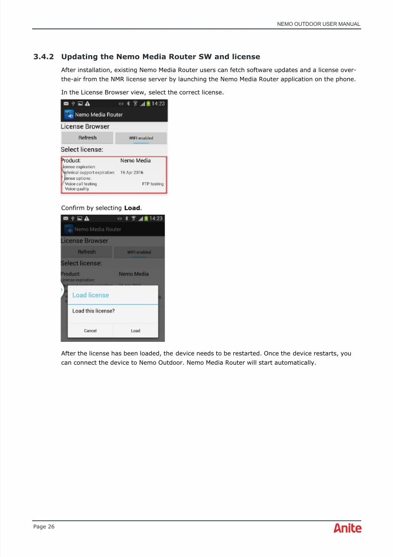
3.4.2 Updating the Nemo Media Router SW and license
After installation, existing Nemo Media Router users can fetch software updates and a license over-the-air from the NMR license server by launching the Nemo Media Router application on the phone.
In the License Browser view, select the correct license.
Confirm by selecting Load .
After the license has been loaded, the device needs to be restarted. Once the device restarts, youcan connect the device to Nemo Outdoor. Nemo Media Router will start automatically.

8/16/2019 Nemo Outdoor User Manual
http://slidepdf.com/reader/full/nemo-outdoor-user-manual 27/391
NEMO OUTDOOR USER MANUAL
Page 27
To check for software updates, make sure that WiFi or mobile data (with HIM devices) is enabled,press the button at the bottom of the NMR main view and select Check for updates .
3.4.3 TeamViewer QuickSupport
When handset isolation modules are used in Nemo Invex II, changing settings and updating theNMR software can be done remotely with TeamViewer QuickSupport without opening the housing.With TeamViewer it is possible to make a remote connection to the test handset via the NemoOutdoor user interface. Please note that one active connection at a time is supported, i.e.connections to several handsets simultaneously are not possible. The laptop running Nemo Outdoormust be connected to the internet, for example, by using a dedicated handset or a USB modemconnected to the controlling laptop. The test handset must be in service and support data services.Packet data must be enabled.
The TeamViewer Quick Support (QS) application and TeamViewer Remote Control add-on moduleare preinstalled to all test handsets delivered by Anite Network Testing with the Nemo Invex
handset isolation modules. TeamViewer must be installed also to the PC running Nemo Outdoor.These applications can be downloaded from the Nemo User Club.
♦ Please note that TeamViewer can be used free of charge only with non-commercial use.Customers using the UI monitoring and controlling with the TeamViewer tools forcommercial use must obtain the licenses directly from TeamViewer( www.teamviewer.com ) .
8/16/2019 Nemo Outdoor User Manual
http://slidepdf.com/reader/full/nemo-outdoor-user-manual 28/391
NEMO OUTDOOR USER MANUAL
Page 28
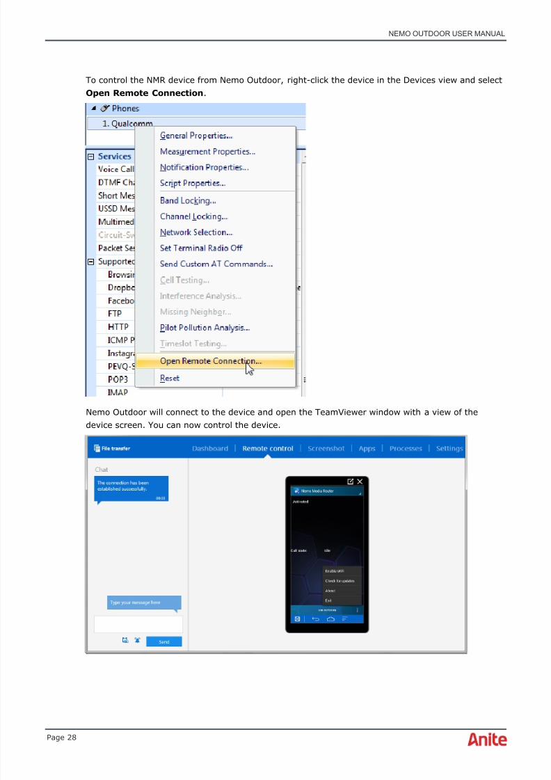
To control the NMR device from Nemo Outdoor, right-click the device in the Devices view and selectOpen Remote Connection .
Nemo Outdoor will connect to the device and open the TeamViewer window with a view of thedevice screen. You can now control the device.
8/16/2019 Nemo Outdoor User Manual
http://slidepdf.com/reader/full/nemo-outdoor-user-manual 29/391

8/16/2019 Nemo Outdoor User Manual
http://slidepdf.com/reader/full/nemo-outdoor-user-manual 30/391
NEMO OUTDOOR USER MANUAL
Page 30
3.6 Nemo Invex II
Nemo Invex II is the most powerful and advanced benchmarking system for testing with largewireless device configurations with high data rates LTE-A Cat 6 and beyond - with rich suite ofapplication testing options. The system enables testing with up to 50 test UEs and with up to threescanners simultaneously with lower power consumption per device, giving operators, networkvendors, regulators, and contractors the possibility to benchmark voice and data services on allavailable wireless technologies in one test drive.
In the new Nemo Invex II design, the main focus has been on reliability in extreme conditions. Thedesign boasts sophisticated built-in cooling and heating and replaceable air filters. The enhancedcapacity of Nemo Invex II offers support for the largest number of test devices in the world. Yet,
power efficiency has not been overlooked: the power usage per UIC has been cut in half thanks tothe innovative design.
The system has improved UPS functions including backup for scanners as well as built-in monitoringfor power, temperature, and current maintaining the measurement system at optimal temperature.Furthermore, USB charging 1.2 compliant ports enable the charging of the measurement devices inlong measurement sessions. Native SuperSpeed USB 3.0 ports support LTE-A Cat 6 test devicesand beyond.
The one size chassis allows totally free mix and match modularity between the chassis via theadvanced Invex Chassis NET communication interface. Compared to current commercialbenchmarking systems, the need for manual cabling has been reduced dramatically. The system is
designed for easy installation and usage in cars with wireless connectivity to the control PC, built-inambient lights and KVM (keyboard, video, and mouse) for improved usability – even inenvironments with less light.

8/16/2019 Nemo Outdoor User Manual
http://slidepdf.com/reader/full/nemo-outdoor-user-manual 31/391
NEMO OUTDOOR USER MANUAL
Page 31
3.7 Indoor measurements
Nemo Outdoor has an indoor mode measurement option in which case Nemo Outdoor can beinstalled on a Tablet PC. Alternatively, a regular laptop can be used as well. As GPS receiverscannot be used indoors, the indoor option offers a marker function to store location data. Just clickmarkers along the measurement route and the route will be drawn on the map. It is also possible touse BTS files with floorplans. With Nemo Walker, test equipment can be easily taken insidebuildings.

8/16/2019 Nemo Outdoor User Manual
http://slidepdf.com/reader/full/nemo-outdoor-user-manual 32/391
NEMO OUTDOOR USER MANUAL
Page 32
4 INSTALLING NEMO OUTDOORSYSTEM
This section provides the basic instructions for installing Nemo Outdoor software and devices. Makesure you have all the listed equipment before starting the software installation. Use the NemoOutdoor setup program to install Nemo Outdoor; that is, do not just copy the Nemo Outdoor filesonto your computer.
♦ Note that for Windows® 7 and Windows® 8, the installation must be run underAdministrator account or other user account with administrative privileges. Note that if
the existing Nemo Outdoor version is 6.2.1.x or older it must be uninstalled via add orremove programs before the Nemo Outdoor 7.x installation can be ran. During SentinelHASP driver installation, you are prompted to restart the computer. Press “Restart later”to continue with the Nemo Outdoor installation.
4.1 Hardware and software requirements
• PC (Lenovo or Dell recommended) with Windows 7 ® Professional (32/64 bit)
• Processor Intel® Core™ i7 2.66GHz or higher
• SSD drive recommended
• 100 MB of free hard disk space for installation and use; 4 GB recommended
• One USB port for copy protection module
• Ethernet port RJ45
• Display resolution 1400 x 900 recommended
• Memory 4GB RAM minimum, 8GB recommended
4.2 Other hardware requirements
The following hardware is also supported for using Nemo Outdoor. Please note that the scanningreceivers and many of the GPS receivers require also +12 V DC power supply (e.g., from cigarettelighter plug).
• External power supply recommended for computer if vehicle mounted
• GPS receiver: (optional, following types are supported)
o Garmin GPS II
o Garmin GPS II Plus
o Garmin GPS III/III+
o Garmin GPS 35
o Garmin V

8/16/2019 Nemo Outdoor User Manual
http://slidepdf.com/reader/full/nemo-outdoor-user-manual 33/391
NEMO OUTDOOR USER MANUAL
Page 33
o Garmin 18 USB
o Trimble Placer 450/455 (TAIP) and GPS antenna unit
o Most other GPS receivers with NMEA 0183 compatible output
♦ Nemo Outdoor software is protected with a HASP USB key (see Licensing)
4.3 Nemo Outdoor software installation
To install or upgrade Nemo Outdoor:
♦ If you have a previous version of Nemo Outdoor installed, please remove it beforeinstallation. Go to Control Panel and select Programs | Uninstall a program. Righ-click onNemo Outdoor and select Uninstall.
♦ Note that installation must be run under Administrator account or other user accountwith administrative privileges.
1. Select Start | Run in the Windows Status bar. Type D: \ Nemo Outdoor \ Nemo Outdoor x.xx.xx in the Open field (xx refers to the version number) and click the OK button. Whenthe Installation program starts, follow the instructions on your screen. We recommend thatyou select the Complete setup type.
2. When the Nemo Outdoor software installation is complete, you will need to restart thecomputer.
To uninstall Nemo Outdoor:
1. Go to Control Panel and select Programs | Uninstall a program . Righ-click on Nemo
Outdoor and select Uninstall .♦ Note that uninstallation must be run under Administrator account or other user account
with administrative privileges.
4.4 Nemo Outdoor device set-up
Below you will find instructions for connecting devices to the Nemo Outdoor measurement system.However, instructions for devices that require a data connection can be found in the DeviceConfiguration Guide.
4.4.1
Connecting a GPS receiver
1. Plug the GPS USB cable into a USB port on your computer.
2. Windows will automatically detect the new device and install the necessary drivers.
3. Start Nemo Outdoor. Open the Configuration Manager , select Device and click the Add button .
4. Click on GPS . Select your GPS model from the list and click Next .
5. Select the USB port to which your GPS receiver is connected. The program automaticallysets the other parameters to match your navigator selection.
6. Click OK . Your GPS receiver is now ready for measurements.
8/16/2019 Nemo Outdoor User Manual
http://slidepdf.com/reader/full/nemo-outdoor-user-manual 34/391
NEMO OUTDOOR USER MANUAL
Page 34
4.4.2 Connecting a scanner
See the Nemo Scanner Guide and Nemo FSR1 User Manual documents for information on how toconnect and start scanners with Nemo Outdoor.
4.4.3 Connecting voice quality devicesPlease refer to the Nemo Voice Quality Guide document for complete installation and configurationinstructions.
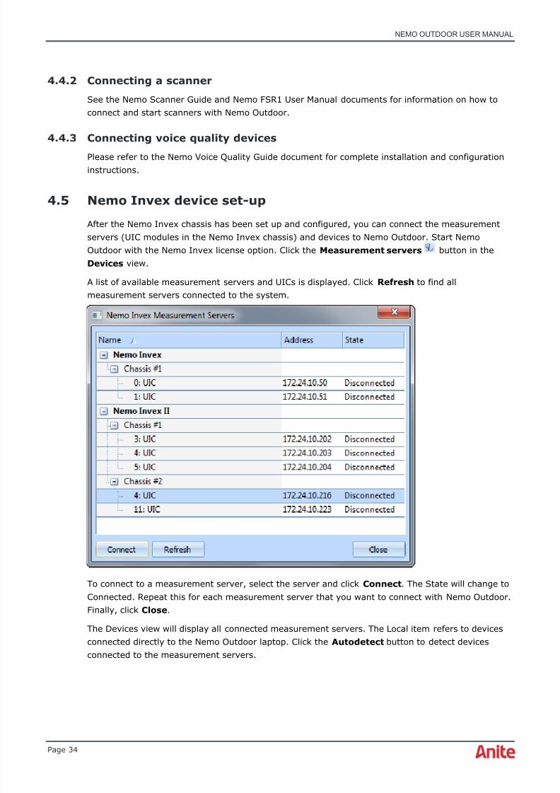
4.5 Nemo Invex device set-up
After the Nemo Invex chassis has been set up and configured, you can connect the measurementservers (UIC modules in the Nemo Invex chassis) and devices to Nemo Outdoor. Start NemoOutdoor with the Nemo Invex license option. Click the Measurement servers button in theDevices view.
A list of available measurement servers and UICs is displayed. Click Refresh to find allmeasurement servers connected to the system.
To connect to a measurement server, select the server and click Connect . The State will change toConnected. Repeat this for each measurement server that you want to connect with Nemo Outdoor.Finally, click Close .
The Devices view will display all connected measurement servers. The Local item refers to devicesconnected directly to the Nemo Outdoor laptop. Click the Autodetect button to detect devicesconnected to the measurement servers.

8/16/2019 Nemo Outdoor User Manual
http://slidepdf.com/reader/full/nemo-outdoor-user-manual 35/391
NEMO OUTDOOR USER MANUAL
Page 35
A list of devices connected to each measurement server is displayed. Define whether the device willbe used for voice quality or data measurements. Read chapter Two data connections on onemeasurement server for more information on having two active data connections on a singlemeasurement server.
If you are adding a scanner, click the scanner name and select the frequency configurationsupported by the scanner.

8/16/2019 Nemo Outdoor User Manual
http://slidepdf.com/reader/full/nemo-outdoor-user-manual 36/391
8/16/2019 Nemo Outdoor User Manual
http://slidepdf.com/reader/full/nemo-outdoor-user-manual 37/391
NEMO OUTDOOR USER MANUAL
Page 37
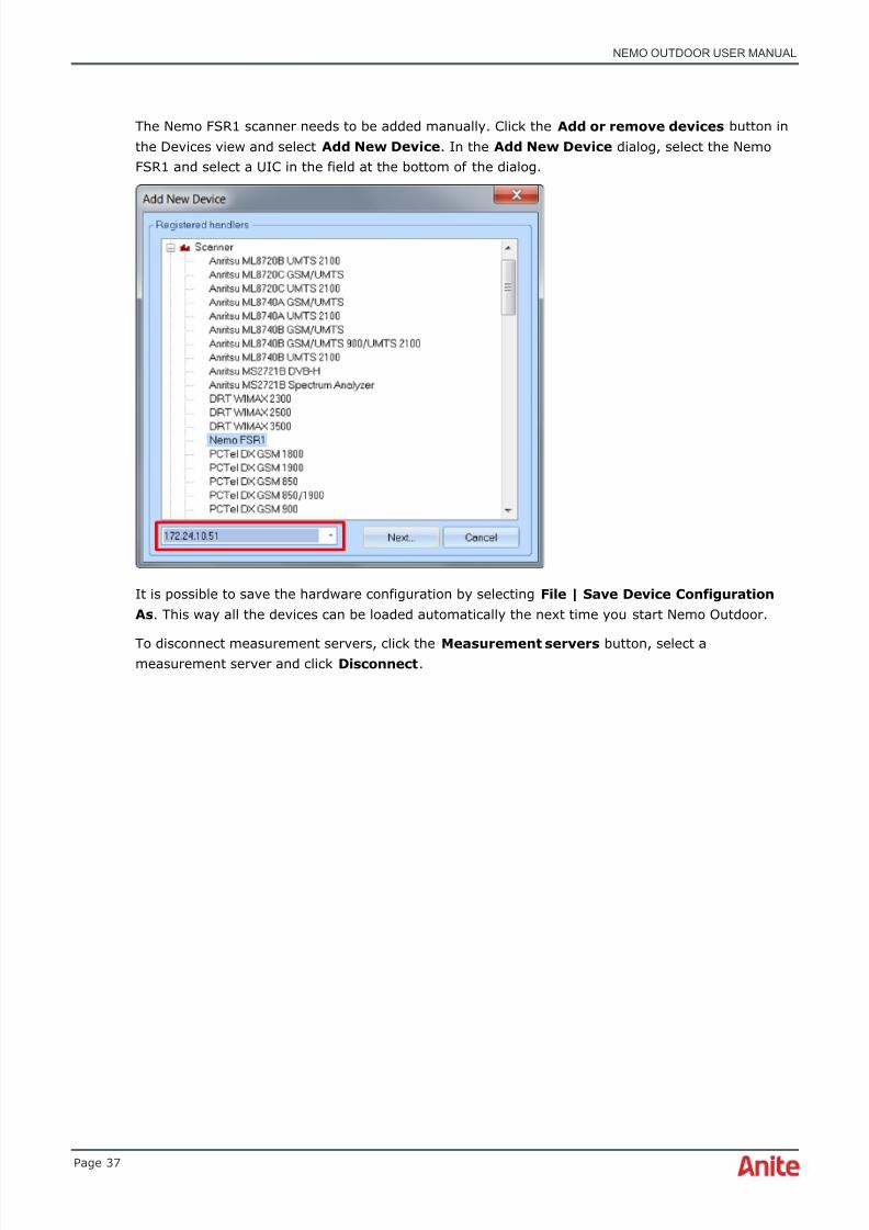
The Nemo FSR1 scanner needs to be added manually. Click the Add or remove devices button inthe Devices view and select Add New Device . In the Add New Device dialog, select the NemoFSR1 and select a UIC in the field at the bottom of the dialog.
It is possible to save the hardware configuration by selecting File | Save Device ConfigurationAs . This way all the devices can be loaded automatically the next time you start Nemo Outdoor.
To disconnect measurement servers, click the Measurement servers button, select ameasurement server and click Disconnect .

8/16/2019 Nemo Outdoor User Manual
http://slidepdf.com/reader/full/nemo-outdoor-user-manual 38/391
NEMO OUTDOOR USER MANUAL
Page 38
4.5.1 Nemo Invex Status view
The Nemo Invex Status view displays information about the current Nemo Invex hardwareconfiguration. The image shows the actual configuration and relevant health information for theselected module. If there are more than one chassis, the chassis are numbered and you can
arrange the view by dragging and dropping the chassis. The Nemo Invex Status view also displaysall possible hardware alerts, such as high/low voltage and battery shutdown.
The UIC and HIM module connections are color-coded. If you select a HIM module from the image,the USB port where the HIM module is connected to will be highlighted with the same color.
You can also reset individual USB ports by right-clicking the USB port in the image and selecting thecommand from the context menu.

8/16/2019 Nemo Outdoor User Manual
http://slidepdf.com/reader/full/nemo-outdoor-user-manual 39/391
NEMO OUTDOOR USER MANUAL
Page 39
The Nemo Invex Systems view displays detailed information about the UICs and the devices. Youcan disconnect UICs and refresh the view. For HIM modules, the device information is shown.
4.5.2 Two data connections on one measurement server
You can have two active data connections on a single measurement server. For example, MMS canbe tested with one test device while another device is performing an FTP transfer. The data routing
option is enabled by default with Nemo Invex allowing more than one active data connection.However, when routing table modifications is enabled, there are some limitations with data testing.For example, it is required that different source IP addresses for data testing are used. This meansthat the host IP address or URL must be different for each test device .

8/16/2019 Nemo Outdoor User Manual
http://slidepdf.com/reader/full/nemo-outdoor-user-manual 40/391
NEMO OUTDOOR USER MANUAL
Page 40
Routing table modification should be disabled when only one active data connection is required.Select View | User Interface Properties and set Enable routing table modifications fordevices to No .
If routing table modification is disabled when performing multi (dual) data testing with onemeasurement server, problems may be caused when several data connections are opened from one
host computer to the terminals. All data connections to be established travel along one connectionbetween the host computer and the terminal, i.e. all data connections are routed via one terminal,not via different terminals and their interfaces. This will distort the test results.
4.6 General guidelines for drive testing
Check the condition of all antennas, cables, and connectors: there should be no tight curves, noslashes or cuts.
Check that connectors are properly connected. Loose connections cause unstable measurements orwrong attenuation of field strength.
Place antennas properly on the roof of the vehicle. Antennas should be installed as symmetrically aspossible and at least one wavelength from the corners and roof windows, and two wavelengths fromeach other. If antennas are too close to each other, it may cause interference.

8/16/2019 Nemo Outdoor User Manual
http://slidepdf.com/reader/full/nemo-outdoor-user-manual 41/391

8/16/2019 Nemo Outdoor User Manual
http://slidepdf.com/reader/full/nemo-outdoor-user-manual 42/391
NEMO OUTDOOR USER MANUAL
Page 42
♦ Check the condition of all RF cables, and connectors: no tight curves, no slashes or cuts.
♦ Check that RF connectors are properly connected. Loose connections cause unstablemeasurements or wrong attenuation of signals. Use the SMA torque wrench to tightenthe connectors
♦ Minimum distance between antennas, at least one wavelength from the corners and roofwindows, and two wavelengths from each other
♦ Individual antennas may have different performance. Therefore use only one antennatype with all test devices
♦ When removing antennas after a drive test, DO NOT pull antennas from the antennacables. Hold the antenna from the base and tilt the antenna away from the cable.
♦ Any unused RF connectors in the RF-splitters must be terminated.
♦ RF-splitters shall be used only for test UEs. If RF-splitters are used also with scanners,separate RF-splitters must be used.
♦ Main and MIMO RF cables of the same UE shall not be connected to the same RF-splitteras it would disable the MIMO/diversity.
8/16/2019 Nemo Outdoor User Manual
http://slidepdf.com/reader/full/nemo-outdoor-user-manual 43/391

8/16/2019 Nemo Outdoor User Manual
http://slidepdf.com/reader/full/nemo-outdoor-user-manual 44/391
NEMO OUTDOOR USER MANUAL
Page 44
♦ Please note that the automatic detection is only available for devices connected with aUSB cable. Furthermore, you may need to select the correct device model from the drop-down menu.
♦ Note that this functionality varies depending on the device vendor. In addition, you may
need to configure the device before connecting it to Nemo Outdoor. Please refer to theNemo Outdoor Device Configuration Guide for instructions on how to do this. The devicemay also require additional configurations in its modem settings.
3. You can start the devices in online mode by clicking the Start Devices button below, startthem in offline mode by clicking the Work Offline button, or refresh the deviceconfiguration by clicking the Refresh button on the bottom right-hand corner of thewindow. This is useful, e.g., when you accidentally unplug a device and plug it in again.
4. PIN code requests should be turned off for all devices but in case there is a pending PINcode request for a test device, a dialog will be displayed where you can enter the PIN code.After pressing OK, PIN code requesting will be disabled from the device.

8/16/2019 Nemo Outdoor User Manual
http://slidepdf.com/reader/full/nemo-outdoor-user-manual 45/391
NEMO OUTDOOR USER MANUAL
Page 45
5. You can also open a workspace file from the Welcome dialog.
6. With the Open a Device Configuration tool you can select saved device configurations.This includes the trace and modem COM ports assigned to the device. If you would like tostart Nemo Outdoor in online mode, select a pre-made device configuration and aworkspace and click Start Devices . All the devices included in the device configuration filewill be activated and you are ready to start measurements.

8/16/2019 Nemo Outdoor User Manual
http://slidepdf.com/reader/full/nemo-outdoor-user-manual 46/391
NEMO OUTDOOR USER MANUAL
Page 46
7. If you prefer setting up the measurement configuration offline, that is, without connectingand starting the measurement devices, select a pre-made device configuration and click theWork Offline button. If you want, you can configure the devices manually and activatethem. When you want to activate the devices, connect the devices to the measurementsystem and click the Work Offline button in the Nemo Outdoor toolbar.
8. The Load a Measurement tool enables you to open a previously viewed measurementwith the attached devices for playback. In the Workspace field you can select a workspacefor the measurement. Click Load Selected Files .

8/16/2019 Nemo Outdoor User Manual
http://slidepdf.com/reader/full/nemo-outdoor-user-manual 47/391
NEMO OUTDOOR USER MANUAL
Page 47
5.1.2 Configuration through Load Device Configuration dialog
To view the Load Device Configuration dialog, click Other… in the Open a Device Configurationfield in the Welcome to Nemo Outdoor window.
1. If you have used Nemo Outdoor previously and saved a device configuration and aworkspace, Nemo Outdoor will ask if you would like to load a device configuration and aworkspace. If you are a first-time user of Nemo Outdoor, go to step 4.

8/16/2019 Nemo Outdoor User Manual
http://slidepdf.com/reader/full/nemo-outdoor-user-manual 48/391

8/16/2019 Nemo Outdoor User Manual
http://slidepdf.com/reader/full/nemo-outdoor-user-manual 49/391
NEMO OUTDOOR USER MANUAL
Page 49
5.1.3 Configuring Nemo Outdoor manually
If you want to configure Nemo Outdoor manually, close the Welcome page or Load DeviceConfiguration dialog when you start Nemo Outdoor. You can go to File | Open Measurement , andselect a saved measurement for playback, or you can open a saved device configuration in File |
Open Device Configuration and start a measurement in online or offline mode. Alternatively, youcan go to Measurement | Add New Device, select a device and configure it for measurements.
In addition, you can use the Autodetect devices functionality which automatically detects apreviously added device and its assigned COM ports. Click the Autodetect Devices button in thetoolbar.
A dialog with a list of previously added devices appears. In the Label field you can type a name for
the device. Select the devices you want to add, define whether the device is in data mode or voicequality mode, and click the Online or Offline button at the bottom of the dialog.
5.1.4 Use case 1. Start measurements automatically upon device startup
The following example case exemplifies the process of setting up Nemo Outdoor to start recordingautomatically when devices are connected and started.
In the Nemo Outdoor main view, perform the following configurations.
1. Go to View | User Interface Properties .
8/16/2019 Nemo Outdoor User Manual
http://slidepdf.com/reader/full/nemo-outdoor-user-manual 50/391
NEMO OUTDOOR USER MANUAL
Page 50
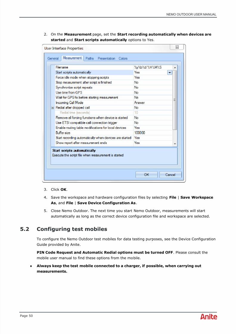
2. On the Measurement page, set the Start recording automatically when devices arestarted and Start scripts automatically options to Yes.
3. Click OK .
4. Save the workspace and hardware configuration files by selecting File | Save WorkspaceAs , and File | Save Device Configuration As .
5. Close Nemo Outdoor. The next time you start Nemo Outdoor, measurements will startautomatically as long as the correct device configuration file and workspace are selected.
5.2 Configuring test mobiles
To configure the Nemo Outdoor test mobiles for data testing purposes, see the Device ConfigurationGuide provided by Anite.
PIN Code Request and Automatic Redial options must be turned OFF . Please consult themobile user manual to find these options from the mobile.
♦ Always keep the test mobile connected to a charger, if possible, when carrying outmeasurements.

8/16/2019 Nemo Outdoor User Manual
http://slidepdf.com/reader/full/nemo-outdoor-user-manual 51/391
NEMO OUTDOOR USER MANUAL
Page 51
5.3 Configuration Manager
Configuring Nemo Outdoor for your environment is accomplished in the Configuration Manager .You can access the view either by pressing Ctrl+M or by clicking the Configuration Manager toolbar button .
The Configuration Manager view consists of several items. Select an item from the list and click theProperties button (if applicable) to edit the item.
The System Properties view shows the general system properties for Nemo Outdoor.
Under Measurement Servers are listed all Nemo Invex measurement servers connected to thesystem. Select a server to view some hardware status information for the server.

8/16/2019 Nemo Outdoor User Manual
http://slidepdf.com/reader/full/nemo-outdoor-user-manual 52/391
NEMO OUTDOOR USER MANUAL
Page 52
5.3.1 Handler information
Under Handler Information , you will find a list of handlers that have been installed on yourcomputer. All the handlers that you have purchased can be found in the Nemo Outdoor productpackage. Each device has its own handler, and in order to use them in Nemo Outdoor, you musthave the corresponding handler installed.
5.3.2 User interface
Under the User Interface item, you will find several items. Double-click on the User Interface Properties item to open the User Interface Properties dialog.

8/16/2019 Nemo Outdoor User Manual
http://slidepdf.com/reader/full/nemo-outdoor-user-manual 53/391
8/16/2019 Nemo Outdoor User Manual
http://slidepdf.com/reader/full/nemo-outdoor-user-manual 54/391
NEMO OUTDOOR USER MANUAL
Page 54
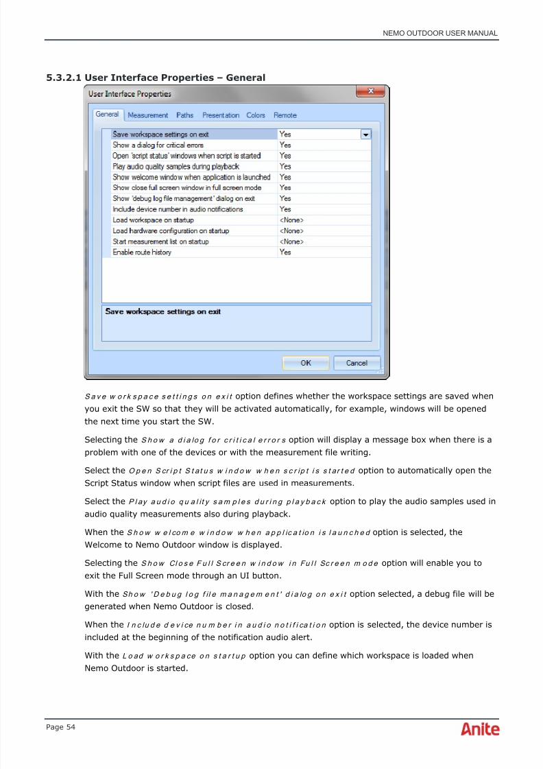
5.3.2.1 User Interface Properties – General
S a v e w o r k s p a c e s e t t i n g s o n e x i t option defines whether the workspace settings are saved whenyou exit the SW so that they will be activated automatically, for example, windows will be openedthe next time you start the SW.
Selecting the S h o w a d i a lo g f o r c r i t i c a l e r r o r s option will display a message box when there is aproblem with one of the devices or with the measurement file writing.
Select the O p e n S cr i p t S t a t u s w i n d o w w h e n s c r ip t i s s t a r t e d option to automatically open theScript Status window when script files are used in measurements.
Select the P l ay a u d i o q u a l i t y s a m p l e s d u r i n g p l a y b a c k option to play the audio samples used inaudio quality measurements also during playback.
When the S h o w w e l co m e w i n d o w w h e n a p p l ic a t io n i s l a u n c h e d option is selected, theWelcome to Nemo Outdoor window is displayed.
Selecting the S h o w Cl o s e F u l l S cr e e n w i n d o w i n Fu l l Sc r e e n m o d e option will enable you toexit the Full Screen mode through an UI button.
With the Sh o w ' D e b u g l o g f i l e m a n a g e m e n t ' d i a lo g o n e x i t option selected, a debug file will begenerated when Nemo Outdoor is closed.
When the I n c lu d e d e v i ce n u m b e r i n a u d i o n o t i f i ca t i o n option is selected, the device number isincluded at the beginning of the notification audio alert.
With the L o ad w o r k s p a ce o n s t a r t u p option you can define which workspace is loaded whenNemo Outdoor is started.

8/16/2019 Nemo Outdoor User Manual
http://slidepdf.com/reader/full/nemo-outdoor-user-manual 55/391
NEMO OUTDOOR USER MANUAL
Page 55
With the L o ad h a r d w a r e c o n f ig u r a t i o n o n s t a r t u p option you can define which hardwareconfiguration is loaded when Nemo Outdoor is started.
With the St a r t m e a su r e m e n t l i st o n s t a r t u p option you can define which measurement list isloaded and started when Nemo Outdoor is started.
When the En a b l e r o u t e h i s t o r y option is selected, a GPX (GPS Exchange Format) file is generatedfrom the measurement. A GPX file is also generated when loading playback files. GPX is a light-weight XML data format for the interchange of GPS data (waypoints, routes, and tracks) betweenapplications and web services on the Internet.
5.3.2.2 User Interface Properties – Measurement
By double-clicking the Measurement item in the Configuration Manager window you will access theMeasurement tab in the User Interface Properties dialog. Here you can make settings affectingall measurements.
Fi l en a m e defines the filename format. The default format is %y%b%d %H%M%S (year-month-day hours-minutes-seconds, e.g., 06May31 165246) but you can use any combination of the itemsbelow. For example, "%y%b%d_%n means that the filename looks as follows: 06May31_1. The lastnumber (%n) is the sequence number for measurement files recorded that day. You can also createcustom filename templates. See chapter Creating Filename Templates .
%a Abbreviated weekday name
%A Full weekday name
%b Abbreviated month name
%B Full month name
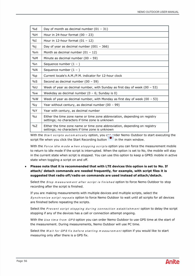
8/16/2019 Nemo Outdoor User Manual
http://slidepdf.com/reader/full/nemo-outdoor-user-manual 56/391
NEMO OUTDOOR USER MANUAL
Page 56
%d Day of month as decimal number (01 – 31)
%H Hour in 24-hour format (00 – 23)
%I Hour in 12-hour format (01 – 12)
%j Day of year as decimal number (001 – 366)
%m Month as decimal number (01 – 12)
%M Minute as decimal number (00 – 59)
%n Sequence number (1 – )
%N Sequence number (1 – )
%p Current locale's A.M./P.M. indicator for 12-hour clock
%S Second as decimal number (00 – 59)
%U Week of year as decimal number, with Sunday as first day of week (00 – 53)
%w Weekday as decimal number (0 – 6; Sunday is 0)
%W Week of year as decimal number, with Monday as first day of week (00 – 53)
%y Year without century, as decimal number (00 – 99)
%Y Year with century, as decimal number
%z Either the time zone name or time zone abbreviation, depending on registrysettings; no characters if time zone is unknown
%Z Either the time zone name or time zone abbreviation, depending on registrysettings; no characters if time zone is unknown
With the S t a r t s c r ip t s a u t o m a t i c a ll y option, you can order Nemo Outdoor to start executing thescript file when you click the Start Recording button in the main window.
With the Fo r c e id l e m o d e w h e n s t o p p i n g s c r i p t s option you can force the measurement mobileto return to idle mode if the script is interrupted. When the option is set to No, the mobile will stayin the current state when script is stopped. You can use this option to keep a GPRS mobile in activestate when toggling a script on and off.
♦ Please note that it is recommended that with LTE devices this option is set to No. Ifattach/ detach commands are needed frequently, for example, with script files it issuggested that radio off/radio on commands are used instead of attach/detach.
Select the S t o p m e a s u r e m e n t a f t e r s c r ip t i s f i n i s h e d option to force Nemo Outdoor to stoprecording after the script is finished.
If you are making measurements with multiple devices and multiple scripts, select theS y n c h r o n i z e s cr i p t r e p e a t s option to force Nemo Outdoor to wait until all scripts for all devicesare finished before repeating the scripts.
Select the P r e v e n t s cr i p t s t o p p i n g d u r i n g c o n n e c t i o n e st a b l i s h m e n t option to delay the scriptstopping if any of the devices has a call or connection attempt ongoing.
With the U s e t im e f r o m GP S option you can order Nemo Outdoor to use GPS time at the start ofthe measurement. During measurements, Nemo Outdoor will use PC time.
Select the W a i t f o r GP S f i x b e f o r e s t a r t i n g m e a su r e m e n t option if you would like to startmeasuring only after there is a GPS fix.
8/16/2019 Nemo Outdoor User Manual
http://slidepdf.com/reader/full/nemo-outdoor-user-manual 57/391
NEMO OUTDOOR USER MANUAL
Page 57
Select the En a b l e a u t o m a t i c m e a su r e m e n t p a u s i n g option to initiate an automatic pause whenGPS velocity goes under X km/h for X seconds or the GPS position is stale (ie. coordinates do notchange). Logging will be resumed automatically after the GPS velocity exceeds the user-specifiedlimit X.
G PS t i m e o f f s e t value specifies the difference between GPS UTC time and local time. This offset isused by handlers when GPS time synchronization is performed.
Select the R e d i a l af t e r d r o p p e d c a l l option to automatically make a new call if a call is droppedduring measurements. Also define the time in seconds after which the call will be redialed.
R e m o v e a l l f o r c i n g f u n c t i o n s w h e n d e v i c e is st a r t e d option deactivates all forcing functionsfrom the device when the device is started.
When the U s e ET SI c o m p a t i b l e c a l l c o n n e c t i o n t r i g g e r option is set to Yes , Outdoor uses theETSI specification-based definition of the start and end time of a call.
En a b l e E TS I c a l l t i m e o u t option changes the call attempt timeout to terminate at CAC 2 event.
By default, call attempt timeout terminates at CAC 1 event. See the Nemo File Format specification(Help | Nemo File Format ) for more information on the events.
With the En a b l e r o u t i n g t a b l e m o d i f i ca t i o n s f o r l o c a l d e v i ce s option users can enable anddisable routing table modification. The option is selected by default. Routing table modificationshould be disabled only with single data testing. If routing table modification is disabled with multidata testing, it can cause problems when several data connections are opened from one hostcomputer to terminals. All data connections to be established travel along one connection betweenthe host computer and the terminal, i.e. all connections are routed via one terminal, not viadifferent terminals and their interfaces. This distorts the test results.
B u f f e r s i z e specifies the number of events stored in the history buffer of the user interface. Thesize of the buffer affects how far back you can view a file during measurement.
Selecting the S t ar t r e c o r d in g a u t o m a t i ca l ly w h e n d e v i ce s a r e s t a r t e d option enables NemoOutdoor to start recording automatically at device startup, and also when changing from offlinemode to online mode.
Selecting the S h o w r e p o r t a f t e r m e a s u r e m e n t e n d s option will display a summary of all testcalls after the measurement is ended.
Selecting the S h o w FT P s e n d d i a lo g b e f o r e s e n d i n g m e a su r e m e n t t o s e r v e r option willdisplay the Send Measurement to FTP Server dialog after the measurement is ended and beforethe log files are sent to an FTP server. See chapter Uploading measurement files to server for more
information.
Selecting the S h o w ' Pa u s e ' d i a lo g w h e n m e a su r e m e n t i s p a u se d option will display a messagewhen the measurement has been paused.
With the S h o w ‘ St o p R e c o r d i n g Q u e r y ’ d i a lo g b e f o r e r e c o r d i n g i s st o p p e d option selected, adialog appears at the end of the measurement to make sure you really want to stop recording.

8/16/2019 Nemo Outdoor User Manual
http://slidepdf.com/reader/full/nemo-outdoor-user-manual 58/391
NEMO OUTDOOR USER MANUAL
Page 58
When the S h o w ‘ En a b l e M i s si n g N e i g h b o r Q u e r y ’ d i a lo g w h e n r e c o r d i n g i s s t a r t e d option isselected, a notification dialog will appear reminding you to enable missing neighbor detection whena scanner and a test terminal are connected to Nemo Outdoor and missing neighbor detection is notcurrently enabled. If you agree to enable the missing neighbor detection functionality through thedialog, the Missing Neighbor Detection dialog will appear. However, note that you are not able toenable the missing neighbor functionality if active measurement properties do not support missingneighbor detection. In that case recording must be stopped and measurement properties changedbefore the missing neighbor functionality can be enabled.
Selecting the S t a r t r e c o r d i n g w h e n i n c o m i n g c a l l is r e c ei v e d option enables Nemo Outdoor tostart recording automatically when a test call is received.
Select the Co m p r e s s m e a s u r e m e n t f i l e( s ) option to automatically compress the files below into asingle measurement archive (ZIP file). After the files are compressed, the original files are deleted.
• measurement files (.nmf)
•
binary files (.nbl)• packet capture files (.pcap)
• marker files (.mrk)
• indoor map files (.tab and image)
R F o f f s e t . In order to prevent measurements with missing/incorrect RF antenna connections, NemoOutdoor performs a check when measurement is started. The RXL/RSSI value of each measuredchannel/carrier is read from each phone and scanner. The value from each channel is compared tothe highest value from all devices. If the measured value is less than X dB (=RF offset value) belowthe highest value, a warning message is displayed to the user with the channel number and the
device name(s).Select the I n c lu d e p a c k e t c a p t u r e l o g s in m e a su r e m e n t f i l e u p l o a d option to send packetcapture logs during measurement file upload.
5.3.2.3 Creating filename templates
You can create templates for naming measurement log files. The template includes parameters(tags) and a list of allowed values for each parameter. The template also specifies the filenameformat which defines how the tags are used in the filename. The templates can be exported andimported.
Double-click the Filename item on the User Interface Properties – Measurement page to open the
Filename Editor. Click the Add button to add a custom parameter.
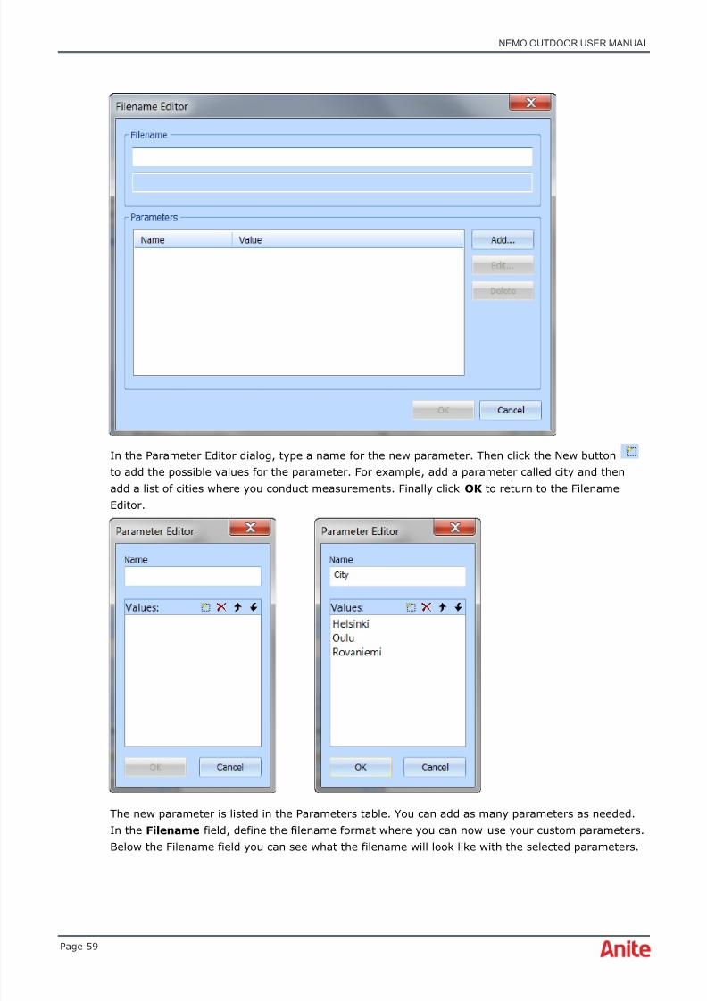
8/16/2019 Nemo Outdoor User Manual
http://slidepdf.com/reader/full/nemo-outdoor-user-manual 59/391
NEMO OUTDOOR USER MANUAL
Page 59
In the Parameter Editor dialog, type a name for the new parameter. Then click the New buttonto add the possible values for the parameter. For example, add a parameter called city and thenadd a list of cities where you conduct measurements. Finally click OK to return to the FilenameEditor.
The new parameter is listed in the Parameters table. You can add as many parameters as needed.In the Filename field, define the filename format where you can now use your custom parameters.Below the Filename field you can see what the filename will look like with the selected parameters.

8/16/2019 Nemo Outdoor User Manual
http://slidepdf.com/reader/full/nemo-outdoor-user-manual 60/391
NEMO OUTDOOR USER MANUAL
Page 60
When you start logging, you will be asked to select a value for the custom parameter. This valuewill be used in the filename.

8/16/2019 Nemo Outdoor User Manual
http://slidepdf.com/reader/full/nemo-outdoor-user-manual 61/391

8/16/2019 Nemo Outdoor User Manual
http://slidepdf.com/reader/full/nemo-outdoor-user-manual 62/391
NEMO OUTDOOR USER MANUAL
Page 62
5.3.2.5 User Interface Properties – Presentation
In the Presentation tab you can define the format in which various parameter values arepresented. For example, to change the file size and buffer size unit in all data transfer configurationdialogs, edit the Size setting in the User Interface Properties – Presentation dialog.
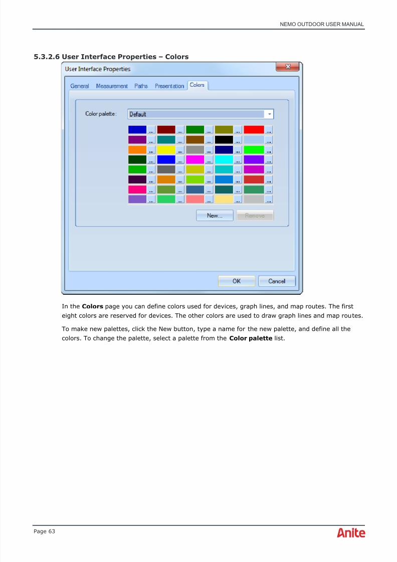
8/16/2019 Nemo Outdoor User Manual
http://slidepdf.com/reader/full/nemo-outdoor-user-manual 63/391
NEMO OUTDOOR USER MANUAL
Page 63
5.3.2.6 User Interface Properties – Colors
In the Colors page you can define colors used for devices, graph lines, and map routes. The firsteight colors are reserved for devices. The other colors are used to draw graph lines and map routes.
To make new palettes, click the New button, type a name for the new palette, and define all thecolors. To change the palette, select a palette from the Color palette list.

8/16/2019 Nemo Outdoor User Manual
http://slidepdf.com/reader/full/nemo-outdoor-user-manual 64/391
NEMO OUTDOOR USER MANUAL
Page 64
5.3.3 Notifications
Notifications are graphical, textual, and audio notifications marking certain events. Nemo Outdoorincludes some premade notifications, but you can also add your own notifications. The notificationscome in handy when you are looking for certain events, parameters, or values in the measurementfile. Depending on your configuration, Nemo Outdoor will either play a sound or display a .pngimage in a graph/map when the defined event occurs during measurements. A textual notification is
displayed in the Output window by default.
By double-clicking a notification, the Notifications window appears. There you can make changes to,for example, sound files and icons associated with the notification.
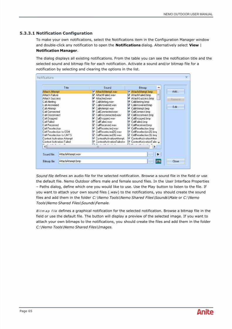
8/16/2019 Nemo Outdoor User Manual
http://slidepdf.com/reader/full/nemo-outdoor-user-manual 65/391

8/16/2019 Nemo Outdoor User Manual
http://slidepdf.com/reader/full/nemo-outdoor-user-manual 66/391
NEMO OUTDOOR USER MANUAL
Page 66
Click the Add button to create new notifications in the Notification Criteria dialog.
T i t l e defines a name for the notification.
N o t i f y w h e n t h e s e c r i t e r i a a r e m e t table displays the criteria for the selected notification. Youcan define a counter that specifies how many times the notification rules must match consecutivelybefore the notification is triggered.
Select the N o t i f y o n l y o n c e w h e n c r i t e r ia a r e m e t option when you want be notified about
certain events only once.Select the parameter that you want to use in the notification. Then define the C o n d i t i o n and Va l u e for the selected parameter and click Add to list to add the new criteria for the notification. You canadd several criteria for each notification. Finally click OK and the notification is saved and added inthe Notifications dialog where you can attach sound and bitmap files to the notification.
The notification is also available in the Measurement Properties | Notifications dialog where youcan activate the notification for a specific device. Click the Device notification settings button inthe Devices view to open the dialog.
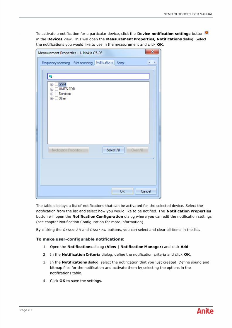
8/16/2019 Nemo Outdoor User Manual
http://slidepdf.com/reader/full/nemo-outdoor-user-manual 67/391
NEMO OUTDOOR USER MANUAL
Page 67
To activate a notification for a particular device, click the Device notification settings buttonin the Devices view. This will open the Measurement Properties, Notifications dialog. Selectthe notifications you would like to use in the measurement and click OK .
The table displays a list of notifications that can be activated for the selected device. Select thenotification from the list and select how you would like to be notified. The Notification Properties button will open the Notification Configuration dialog where you can edit the notification settings(see chapter Notification Configuration for more information).
By clicking the S e l e ct A l l and C l e a r A l l buttons, you can select and clear all items in the list.
To make user-configurable notifications:
1. Open the Notifications dialog ( View | Notification Manager ) and click Add .
2. In the Notification Criteria dialog, define the notification criteria and click OK .
3. In the Notifications dialog, select the notification that you just created. Define sound andbitmap files for the notification and activate them by selecting the options in thenotifications table.
4. Click OK to save the settings.
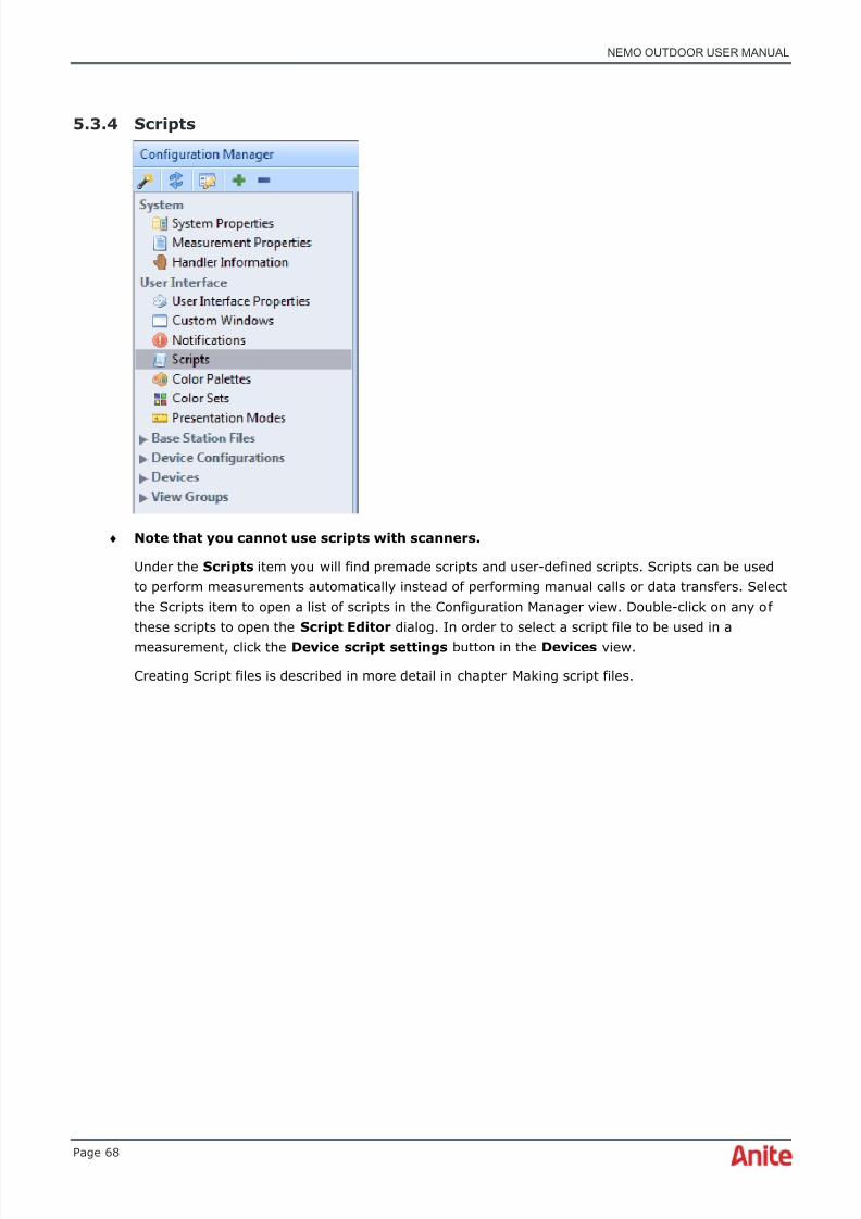
8/16/2019 Nemo Outdoor User Manual
http://slidepdf.com/reader/full/nemo-outdoor-user-manual 68/391
NEMO OUTDOOR USER MANUAL
Page 68
5.3.4 Scripts
♦ Note that you cannot use scripts with scanners.
Under the Scripts item you will find premade scripts and user-defined scripts. Scripts can be usedto perform measurements automatically instead of performing manual calls or data transfers. Selectthe Scripts item to open a list of scripts in the Configuration Manager view. Double-click on any ofthese scripts to open the Script Editor dialog. In order to select a script file to be used in ameasurement, click the Device script settings button in the Devices view.
Creating Script files is described in more detail in chapter Making script files.

8/16/2019 Nemo Outdoor User Manual
http://slidepdf.com/reader/full/nemo-outdoor-user-manual 69/391
NEMO OUTDOOR USER MANUAL
Page 69
5.3.5 Base station files
Under the Base Station Files item you will find loaded base station files. Select a BTS file to viewthe BTS information in the Configuration Manager view. Click the – button to remove the BTS file.
5.3.6 Device configurations

8/16/2019 Nemo Outdoor User Manual
http://slidepdf.com/reader/full/nemo-outdoor-user-manual 70/391

8/16/2019 Nemo Outdoor User Manual
http://slidepdf.com/reader/full/nemo-outdoor-user-manual 71/391
NEMO OUTDOOR USER MANUAL
Page 71
5.3.7.1 Device configuration for mobiles and modems
The L a b e l field allows you to give a label such as a comment or a name for the phone, and makesit easier to identify devices during measurement and post processing. The label can be seen in the
Nemo Outdoor user interface during a measurement and playback, and the information is alsostored in the log file header.
T r a c e p o r t and M o d e m p o r t selections are device-specific. Please refer to the DeviceConfiguration Guide for more detailed information.
K o d i a k P T T p o r t defines the COM port for a Kodiak PTT device. Please refer to chapter KodiakPush-to-Talk for more information.
N e m o M e d i a Ro u t e r option is used to enable Nemo Media Router. Select Automatic to enable theoption.
C S d a t a c o n n e c t i o n option gives a list of all the circuit-switched data connections that have beenconfigured on your computer. If you are making CS data measurements, select a connection here.See the Device Configuration Guide provided by Anite for detailed instructions for configuring testdevices.
P S d a t a c o n n e c t i o n option gives a list of all the packet-switched data connections that have beenconfigured on your computer. If you are making PS data measurements, select a connection here.See the Device Configuration Guide provided by Anite for detailed instructions for configuring testdevices.
A n t e n n a g a i n and C a b l e l o s s are antenna-related parameters and they are used in the conversionfrom dBm to dBuV/m. This parameter is needed only if you are using external antennas. If you areusing the internal antenna of each phone, leave these values blank.

8/16/2019 Nemo Outdoor User Manual
http://slidepdf.com/reader/full/nemo-outdoor-user-manual 72/391

8/16/2019 Nemo Outdoor User Manual
http://slidepdf.com/reader/full/nemo-outdoor-user-manual 73/391
NEMO OUTDOOR USER MANUAL
Page 73
The above examples can only be used with antennas received from Anite or Smarteq. If you areusing antennas from other antenna manufacturers, you will have to ask the antenna gain and cableloss information from the manufacturer.
Vo i ce q u a l i t y a l g o r i t h m defines which voice quality algorithms are used in voice qualitymeasurements.
If you select the Invex isolation module option, you can also make echo measurements. Select theEn a b l e e ch o m e a su r e m e n t option to start logging the echo-related parameters. With theAdvanced echo OEM library provided by Opticom it is possible to measure echo from audio withboth PESQ and POLQA algorithms. Echo measurements require an additional license and it isavailable with Nemo Invex using a handset isolation module. Echo measurements are not supportedwith commercial sound cards, such as, Terratec DMX6 Fire or Maya44.
Select the N e m o a u d io m o d u l e option to use the Nemo audio module for voice qualitymeasurements. You can define the port where the Nemo voice quality unit is connected in the drop-down menu.
Select the S o u n d c a r d c h a n n e l option to use the USB sound card for voice quality measurements.Select the applicable sound card channel in the drop-down menu.
Select the I n v e x i so l a t io n m o d u l e option to use a terminal with an Invex isolation module forvoice quality measurements.
Select the Vo I P o n l y option to make voice quality measurements (POLQA) over a VoIP connection.If you select this option make the appropriate settings in the VoIP Call Configuration dialog (seeVoIP calls) .
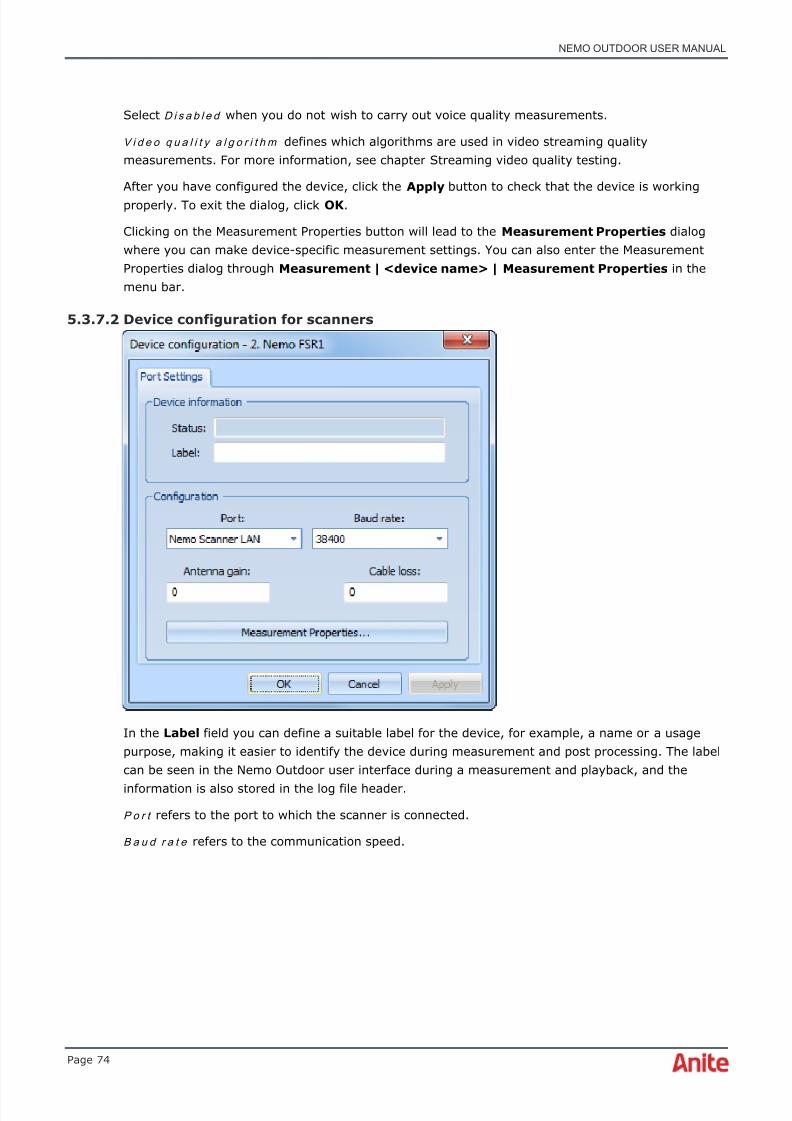
8/16/2019 Nemo Outdoor User Manual
http://slidepdf.com/reader/full/nemo-outdoor-user-manual 74/391

8/16/2019 Nemo Outdoor User Manual
http://slidepdf.com/reader/full/nemo-outdoor-user-manual 75/391
NEMO OUTDOOR USER MANUAL
Page 75
A n t e n n a g a i n and C a b l e l o s s are antenna-related parameters and they are used in the conversionfrom dBm to dBuV/m. This parameter is needed only if you are using external antennas. If you areusing the internal antenna of each phone, leave these values blank.
Antenna
type
Frequency
range
Antenna
gain(dBd)
Impedance VSWR 1 Max
power
Polarization Cable
loss
Cable &
connector
1140.27 824–894/1710–1880/1850–2170MHz
0 dBd 50 ohm 2:1 @specified freq.
10 W Linearvertical
-0.55/-0.82dB/m
Mini LowLoss 2.5m, SMAmale
1140.26 890–960/1850–1990/1710–2170MHz
0 dBd 50 ohm 2:1 @specified freq.
10 W Linearvertical
Mini LowLoss 2.5m, SMAmale
The above examples can only be used with antennas received from Anite or Smarteq. If you areusing antennas from other antenna manufacturers, you will have to ask the antenna gain and cableloss information from the manufacturer.
Clicking on the Measurement Properties button will lead to the Measurement Properties dialogwhere you can make device-specific measurement settings (see Measurement Properties) .
After you have configured the device, click the Apply button to check that the device is workingproperly. To exit the dialog, click OK .
5.3.7.3 Device configuration for GPS receivers
In the Label field you can define a label for the GPS device, for example, a name or a usagepurpose, making it easier to identify devices during measurement and post processing. The labelcan be seen in the Nemo Outdoor user interface during a measurement and playback, and theinformation is also stored in the log file header.

8/16/2019 Nemo Outdoor User Manual
http://slidepdf.com/reader/full/nemo-outdoor-user-manual 76/391
NEMO OUTDOOR USER MANUAL
Page 76
S e r ia l p o r t refers to the port to which the GPS receiver is connected.
B a u d r a t e refers to the communication speed. The available values are 1200, 2400, 4800, and9600.
D a t a b i t s , P a r i t y and S t o p b i t s are other communication-related parameters. The available valuesfor Data bits are 5, 6, 7, and 8, the options for Parity are Even, None, and Odd. The default valuefor Stop bits is 1. You should set these values the same as in your GPS. Check your GPS receiverdocumentation.
After you have configured the device, click the Apply button to check that the device is workingproperly. To exit the dialog, click OK .
5.3.8 View groups
Under the View Groups item are listed all the view groups that are currently loaded. View groupsare sets of windows that are open at the same time. You can add a new view group from the plusicon , and remove a view group by selecting the item and clicking on the minus icon . When youselect a view group in the Configuration Manager, the right-hand panel displays the views that aresaved in the view group. You can define properties for each view by double-clicking the view name.
See chapter View groups for more information on using the view groups.
5.4 Measurement Properties dialog
The Measurement Properties dialog contains several pages and the contents depend on the devicetype (mobile or scanner), on the device model, and on the technologies supported by the device.
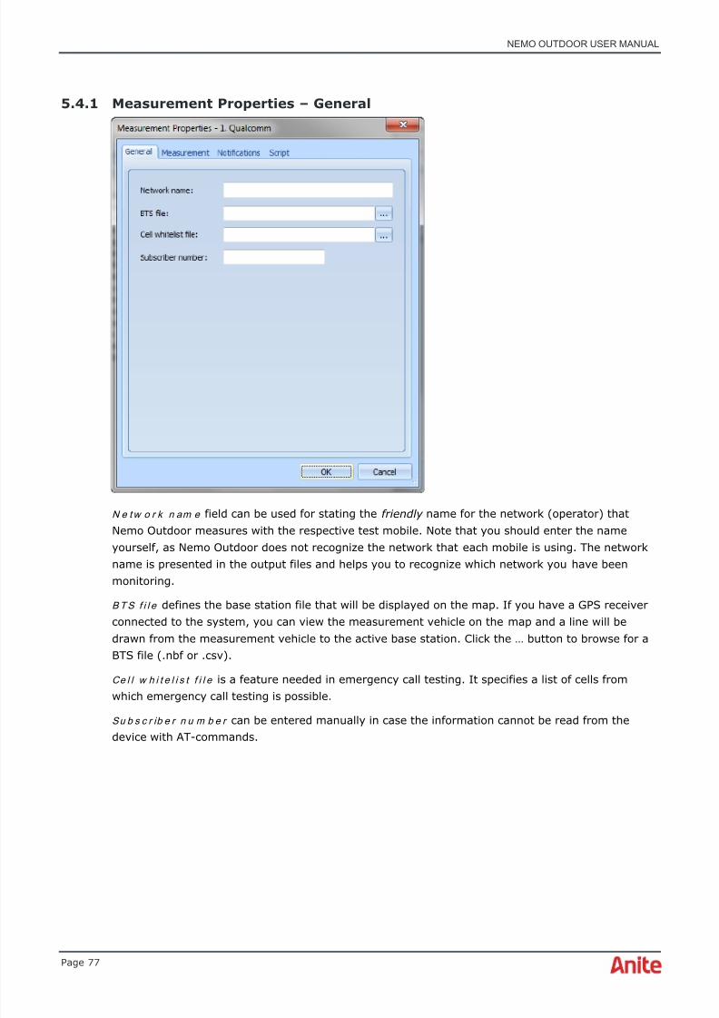
8/16/2019 Nemo Outdoor User Manual
http://slidepdf.com/reader/full/nemo-outdoor-user-manual 77/391
NEMO OUTDOOR USER MANUAL
Page 77
5.4.1 Measurement Properties – General
N e t w o r k n am e field can be used for stating the friendly name for the network (operator) that
Nemo Outdoor measures with the respective test mobile. Note that you should enter the nameyourself, as Nemo Outdoor does not recognize the network that each mobile is using. The networkname is presented in the output files and helps you to recognize which network you have beenmonitoring.
B T S f i l e defines the base station file that will be displayed on the map. If you have a GPS receiverconnected to the system, you can view the measurement vehicle on the map and a line will bedrawn from the measurement vehicle to the active base station. Click the … button to browse for aBTS file (.nbf or .csv).
Ce l l w h i t e l i s t f i l e is a feature needed in emergency call testing. It specifies a list of cells fromwhich emergency call testing is possible.
Su b s c r ib e r n u m b e r can be entered manually in case the information cannot be read from thedevice with AT-commands.
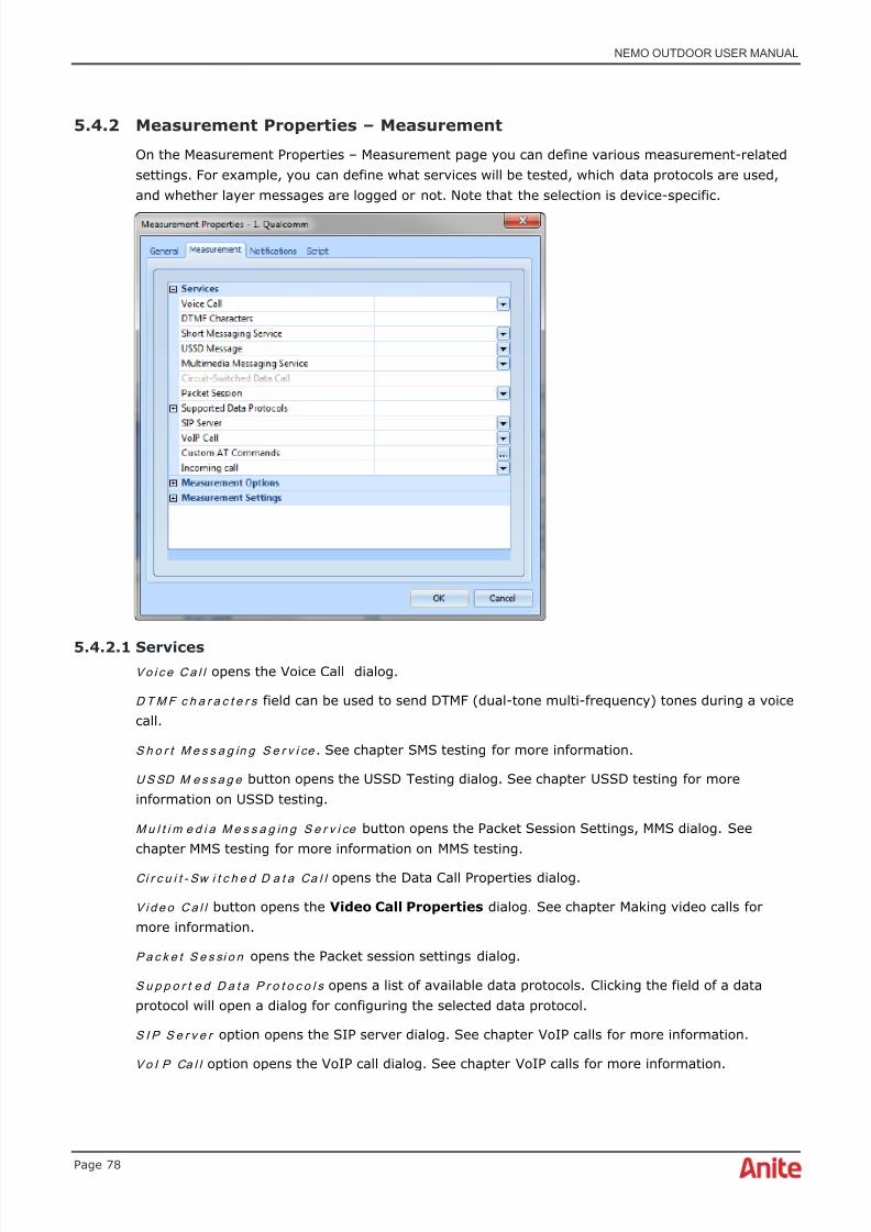
8/16/2019 Nemo Outdoor User Manual
http://slidepdf.com/reader/full/nemo-outdoor-user-manual 78/391

8/16/2019 Nemo Outdoor User Manual
http://slidepdf.com/reader/full/nemo-outdoor-user-manual 79/391
NEMO OUTDOOR USER MANUAL
Page 79
Cu s t o m AT Co m m a n d s offers the possibility to run custom AT commands with certain testterminals. The available commands are device-specific. Type in the AT command and click SendCommand . The AT commands and responses are saved in the measurement file.
I n c o m i n g ca l l option opens the Incoming Call Configuration dialog. See chapter Receive call for more information.
5.4.2.2 Measurement options
Under Measurement Options you can enable and disable various measurement options such aslayer messages. If you disable some of the options, the disabled messages will not be recorded inthe measurement file. This will decrease output file size. The selection depends on themeasurement device used. The parameters in the Measurement Options list vary depending on thedevice. These options are also accessible through the Devices view.
When the E V RC M O S c o m p e n s a t i o n option is enabled, the Evaluation of Speech Quality (PESQ)tool is biased against the Enhanced Variable Rate Codec (EVRC) used in CDMA networks and othercodecs in this family (EVRC-B and EVRC-WB). MOS value is incremented by 0.318MOS.
I n c o m i n g ca l l m o d e defines how incoming calls are handled. The options are answer , reject , andignore . You can also define a delay (in seconds) when the Answer option is selected.

8/16/2019 Nemo Outdoor User Manual
http://slidepdf.com/reader/full/nemo-outdoor-user-manual 80/391
NEMO OUTDOOR USER MANUAL
Page 80
With Qualcomm-based terminals there are several different Vo i ce c a ll m e t h o d s . Voice call methodis device specific. Trace interface 2 method should be used with MultiRAB testing. When a voice callis terminated, the PS data connection might be released with UEs using the Trace interface callmethod to make voice calls. In such a case, it is recommended to use the Trace interface 2 callmethod. Please check the Device Configuration Guide or release note for device-specificinformation.
With Qualcomm-based terminals there is a number of different V i d e o ca l l m e t h o d s and thecorrect method must be selected to be able to make video call testing.
With the S e le c t A M R c o d e c s option, you can force a device to use a certain AMR codec mode. Forexample, when a UE is forced to the WCDMA AMR WB codec, it can freely use any WB AMR codecfrom 6.6 kbps to 23.85 kbps.
♦ Note that the Enable RLC Data messages item should not be enabled with dataconnections 384kbit/s or higher as this may cause instability in the measurementterminal.
♦ To view data in Packet decoder grids during playback, you need to enable the packet
decoding function prior to performing data measurements. Select Full or Partial in theEnable IP Capture field. A separate .pcap-file will be generated for the measurement. Thisfile needs to accompany the measurement file in the same folder when viewing anddecoding packet capture information in Packet Decoder grids in Nemo Outdoor.
5.4.2.3 Measurement settings
With the Fo r c e d e t a ch w h e n e n t e r i n g i d l e m o d e option selected, a GPRS detach is forced whenthe measurement device enters idle mode.
En a b l e d i a g n o s t i c d a t a l o g g i n g option enables/disables Qualcomm raw packet logging. Whendiagnostics data logging is enabled, you can select individual Qualcomm trace messages to bestored in a separate binary file (.NBL). Both NBL and NMF files can be opened and played back withNemo Outdoor and Qualcomm raw data messages can be fully decoced in the grid view for furtheranalysis. This functionality requires the Diagnostics Data Logging option OD0700-00.
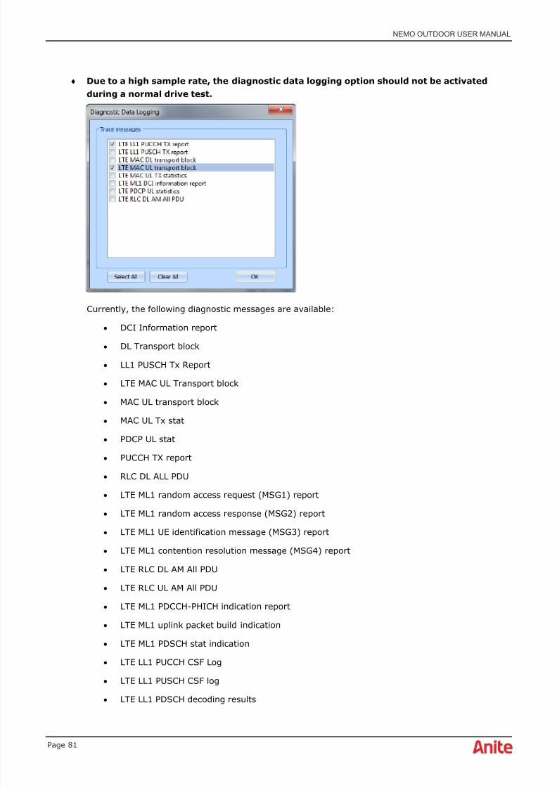
8/16/2019 Nemo Outdoor User Manual
http://slidepdf.com/reader/full/nemo-outdoor-user-manual 81/391
NEMO OUTDOOR USER MANUAL
Page 81
♦ Due to a high sample rate, the diagnostic data logging option should not be activatedduring a normal drive test.
Currently, the following diagnostic messages are available:
• DCI Information report
• DL Transport block
• LL1 PUSCH Tx Report
• LTE MAC UL Transport block
• MAC UL transport block
• MAC UL Tx stat
• PDCP UL stat
• PUCCH TX report
• RLC DL ALL PDU
• LTE ML1 random access request (MSG1) report
• LTE ML1 random access response (MSG2) report
• LTE ML1 UE identification message (MSG3) report
• LTE ML1 contention resolution message (MSG4) report• LTE RLC DL AM All PDU
• LTE RLC UL AM All PDU
• LTE ML1 PDCCH-PHICH indication report
• LTE ML1 uplink packet build indication
• LTE ML1 PDSCH stat indication
• LTE LL1 PUCCH CSF Log
• LTE LL1 PUSCH CSF log
• LTE LL1 PDSCH decoding results

8/16/2019 Nemo Outdoor User Manual
http://slidepdf.com/reader/full/nemo-outdoor-user-manual 82/391
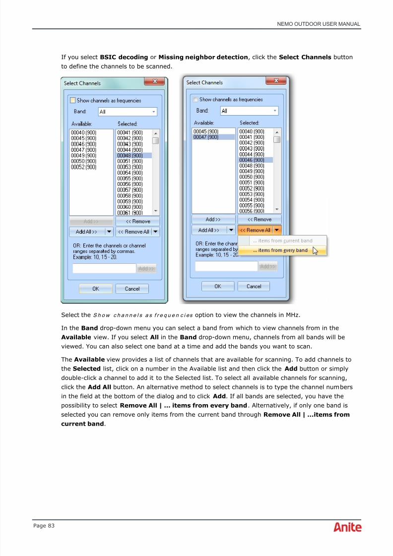
8/16/2019 Nemo Outdoor User Manual
http://slidepdf.com/reader/full/nemo-outdoor-user-manual 83/391
NEMO OUTDOOR USER MANUAL
Page 83
If you select BSIC decoding or Missing neighbor detection , click the Select Channels buttonto define the channels to be scanned.
Select the S h o w c h a n n e l s a s f r e q u e n c i es option to view the channels in MHz.
In the Band drop-down menu you can select a band from which to view channels from in theAvailable view. If you select All in the Band drop-down menu, channels from all bands will beviewed. You can also select one band at a time and add the bands you want to scan.
The Available view provides a list of channels that are available for scanning. To add channels tothe Selected list, click on a number in the Available list and then click the Add button or simplydouble-click a channel to add it to the Selected list. To select all available channels for scanning,
click the Add All button. An alternative method to select channels is to type the channel numbersin the field at the bottom of the dialog and to click Add . If all bands are selected, you have thepossibility to select Remove All | ... items from every band . Alternatively, if only one band isselected you can remove only items from the current band through Remove All | ...items fromcurrent band .

8/16/2019 Nemo Outdoor User Manual
http://slidepdf.com/reader/full/nemo-outdoor-user-manual 84/391
NEMO OUTDOOR USER MANUAL
Page 84
If you select the Top-N option, click the Top-N Configuration button to select channels.
In the Top-N Configuration dialog you can set the Start and Stop ARFCN range between whichthe Top-N channels are recorded. Define the number of strongest channels to be searched in theTop-N field. The maximum number of Top-N channels is 32. You can click on the Clear all button to
clear the table.

8/16/2019 Nemo Outdoor User Manual
http://slidepdf.com/reader/full/nemo-outdoor-user-manual 85/391
NEMO OUTDOOR USER MANUAL
Page 85
5.4.4 Measurement Properties – Pilot scanning with mobiles
♦ Note that this page is only visible in a phone's Measurement Properties dialog if theterminal supports pilot scanning.
The En a b l e p i lo t s ca n n i n g option must be selected to activate pilot scanning for the mobile.
Select a value for the C PI CH R S CP t h r e s h o l d field. The device will only report cells with CPICHRSCP above the set value.
The To p - N scanning functionality can be used for scanning the strongest pilots in UMTS. With Top-N scanning it is possible to get Top-N channel results for each band. The benefits also include thepossibility to benchmark different operators.
When the M i s si n g n e i g h b o r d e t e c t i o n option is selected, the missing neighbor information event(NMISS) is written in the log file. You can view the missing neighbor information, for example, in agrid view.
Click the Top-N Configuration button to enter the Select Channels dialog.
5.4.5 Measurement Properties – Frequency, pilot, and spectrum scanning withscanners
Please refer to the separate scanner guides, Nemo FSR1 User Manual and Nemo Scanner Guide,included in the product package.
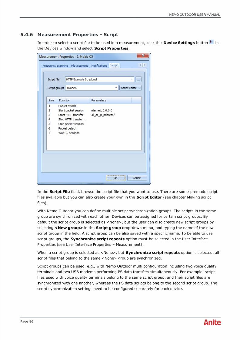
8/16/2019 Nemo Outdoor User Manual
http://slidepdf.com/reader/full/nemo-outdoor-user-manual 86/391
NEMO OUTDOOR USER MANUAL
Page 86
5.4.6 Measurement Properties - Script
In order to select a script file to be used in a measurement, click the Device Settings button inthe Devices window and select Script Properties .
In the Script File field, browse the script file that you want to use. There are some premade scriptfiles available but you can also create your own in the Script Editor (see chapter Making scriptfiles) .
With Nemo Outdoor you can define multiple script synchronization groups. The scripts in the samegroup are synchronized with each other. Devices can be assigned for certain script groups. Bydefault the script group is selected as <None>, but the user can also create new script groups byselecting <New group> in the Script group drop-down menu, and typing the name of the newscript group in the field. A script group can be also saved with a specific name. To be able to use
script groups, the Synchronize script repeats option must be selected in the User InterfaceProperties (see User Interface Properties – Measurement) .
When a script group is selected as <None>, but Synchronize script repeats option is selected, allscript files that belong to the same <None> group are synchronized.
Script groups can be used, e.g., with Nemo Outdoor multi configuration including two voice qualityterminals and two USB modems performing PS data transfers simultaneously. For example, scriptfiles used with voice quality terminals belong to the same script group, and their script files aresynchronized with one another, whereas the PS data scripts belong to the second script group. Thescript synchronization settings need to be configured separately for each device.

8/16/2019 Nemo Outdoor User Manual
http://slidepdf.com/reader/full/nemo-outdoor-user-manual 87/391
NEMO OUTDOOR USER MANUAL
Page 87
6 DURING MEASUREMENTS
When Nemo Outdoor is performing the user defined test measurement, you can view the process ina number of graphs, grids, and maps. The graph and grid windows are fully user configurable. Inthe following chapters, the most common tasks are presented in more detail and some examplesare given to illustrate their use. If you have any problems in starting the measurements, seechapter Troubleshooting.
6.1 Textual notes
It is possible to add textual notes at points of interest during measurements. Click the Add TextualNote button in the toolbar. Note that you need to start recording before the button is activated.

8/16/2019 Nemo Outdoor User Manual
http://slidepdf.com/reader/full/nemo-outdoor-user-manual 88/391
NEMO OUTDOOR USER MANUAL
Page 88
You can either type the note in the field or select a predefined text and click OK . To save newpredefined notes, type in the text, click the arrow next to the OK button and select Addpredefined text . Next time the text will be available in the drop-down menu at the top.
The textual notes can be viewed during playback, for example, in an events grid.
6.2 Nemo Commander remote control option for Nemo Outdoor/Invex
Nemo Outdoor measurement units can be remotely configured and controlled with NemoCommander. This requires the Remote option in Nemo Outdoor/Nemo Invex and the NemoCommander SW. All the same user interface functionalities are available in remote mode as innormal mode. For more information on the Nemo Commander SW, please refer to the NemoCommander user manual.
In order to use TeamViewer for controlling the Nemo Outdoor units, the TeamViewer application
must be installed on the Nemo Outdoor laptop. Please refer to the Nemo Commander user manualfor more information.
To configure the Remote mode, select Remote | Settings .
♦ Note that if the Remote menu does not appear in the menu bar, your Nemo Outdoorlicense does not have the Remote option (product code OD0700-01).
On the User Interface Properties – Remote page, select Yes for Enable remote mode . WhenRemote mode is enabled, Nemo Outdoor will automatically perform a maintenance session atstartup. Also the manual Maintenance tool is activated in the Remote menu.
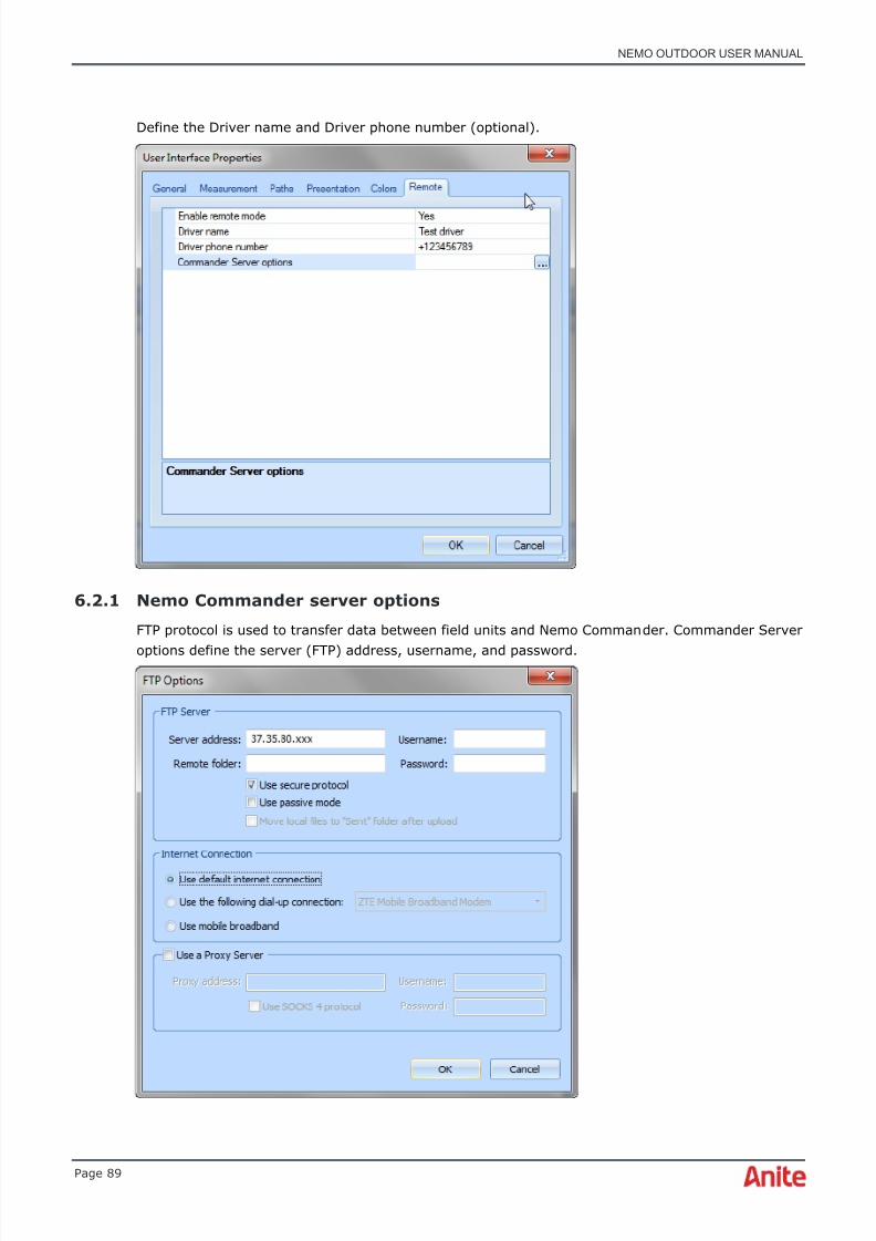
8/16/2019 Nemo Outdoor User Manual
http://slidepdf.com/reader/full/nemo-outdoor-user-manual 89/391
NEMO OUTDOOR USER MANUAL
Page 89
Define the Driver name and Driver phone number (optional).
6.2.1 Nemo Commander server options
FTP protocol is used to transfer data between field units and Nemo Commander. Commander Server
options define the server (FTP) address, username, and password.

8/16/2019 Nemo Outdoor User Manual
http://slidepdf.com/reader/full/nemo-outdoor-user-manual 90/391
NEMO OUTDOOR USER MANUAL
Page 90
Add the FTP server host name or IP address.
♦ Leave Username, Remote folder, and Password fields empty. This information isgenerated by the system and the fields are updated after the initial maintenance session.
Use secure protocol : Select in case SFTP protocols is used in the server
Use passive mode : With passive mode, the client always opens those new connections so thefirewall does not block the connection
6.2.2 Initial field unit configuration
1. Build the Nemo Outdoor HW configuration, in other words, connect the measurementdevices (phones, USB modems, and scanners) to the Nemo Outdoor laptop.
2. A dedicated PS data connection (e.g. 3G/4G USB modem or smartphone, active only duringmaintenance sessions) is required to establish the connection between Nemo Outdoor andNemo Commander. Connect the device to the Nemo Outdoor laptop and install the
necessary drivers. Do not add the device to Nemo Outdoor as it will not be used as ameasurement device.
3. Synchronize date and time settings between the Nemo Outdoor and Nemo Commandercomputers.
4. Enable the Remote mode on the Nemo Outdoor User Interface Properties – Remote page and define the Commander Server settings.
5. Select Maintenance from the Remote menu.
• The Nemo Outdoor unit connects and registers to Nemo Commander.
• The HW configuration of the Nemo Outdoor unit is uploaded to Nemo Commander.
♦ Step 5, Maintenance, must be repeated every time the HW configuration changes.
6.2.3 Measurement workflow
1. Nemo Commander : Define measurement sessions for the field unit(s)
• Scripts for each device
• Session start/stop time
2. Nemo Outdoor : Power on laptop and all test devices
• Nemo Outdoor starts automatically

8/16/2019 Nemo Outdoor User Manual
http://slidepdf.com/reader/full/nemo-outdoor-user-manual 91/391
NEMO OUTDOOR USER MANUAL
Page 91
• Status report is uploaded to Nemo Commander
• Measurement session is downloaded from Nemo Commander
• Measurements are started automatically according to the downloaded configuration
• Periodic status reports are sent to Nemo Commander (configured in Nemo Commander)3. Nemo Commander : Verify the HW configuration from latest status report (optional)
• If incorrect, contact driver
4. Nemo Outdoor : End measurements
• Measurements are stopped at the scheduled time
• Log files and status reports are uploaded to Nemo Commander
6.2.4 Events reported by Nemo Outdoor/Nemo Invex to Nemo Commander
The following measurement events are reported by Nemo Outdoor and Nemo Invex to NemoCommander.
Status events:
• Start measurement
• Stop measurement
• GSP fix lost
• GSP fix acquired
• Device responding
• Device power off request
• Device restart
• High voltage shutdown
• Battery operation
• Battery shutdown
Errors:
• Start measurement failed
• Device not responding
Warnings:
• Low voltage
• High voltage
• Battery voltage low

8/16/2019 Nemo Outdoor User Manual
http://slidepdf.com/reader/full/nemo-outdoor-user-manual 92/391
NEMO OUTDOOR USER MANUAL
Page 92
6.3 Making scanning measurements
6.3.1 With a scanner
In order to measure with a scanner, just start the recording by clicking the Start Recording
button. Nemo Outdoor will start writing the measurement data in a file.
6.3.2 With a mobile
To carry out frequency scanning with a mobile phone, first make sure that the terminal modelsupports the scanning feature.
To do frequency scanning, select Measurement control | Start Single Shot Scanning , orMeasurement control | Start Continuous Scanning .
To end a scanning measurement, select Measurement control | Stop Scanning .
6.4 Making voice calls
To make voice calls:
1. In the Measurement Properties, Measurement page (see Measurement Properties –Measurement) , insert the phone number that you wish to use in the test call in the VoiceCall field. Click OK .
2. Select Start Voice Call from the Device Commands menu or from the Measurementmenu.Alternatively, you can activate a script by clicking the Start/Stop Scripts button.
♦ Note that after you have activated the script, you cannot control the measurementmanually until the script is finished or you interrupt the script by clicking the Start/StopScripts button.
3. When you wish to finish the call in manual mode, select Stop Voice Call from the DeviceCommands menu . If you are running a script, wait until the script is finished.

8/16/2019 Nemo Outdoor User Manual
http://slidepdf.com/reader/full/nemo-outdoor-user-manual 93/391
NEMO OUTDOOR USER MANUAL
Page 93
6.4.1 Voice Call Configuration
Voice call settings are needed to establish the voice calls and to make voice quality measurements.Click the Voice Call button in the Measurement Properties , Measurement dialog and the VoiceCall Configuration dialog will be opened.
P h o n e n u m b e r defines the number to be called. It must be a valid phone number. The numbermust be such that the line stays open for a user-defined time and some speech or sound istransferred on the line. The Number field can contain up to 17 characters.
Ca l l d u r a t i o n determines the time that the call lasts in seconds.
Fixed : The duration timer is started from the channel assignment. The range of duration values isfrom 1 to 1,000,000 seconds. Note that the maximum value of this parameter is the same as thevalue you have set as the Delay Between Call Attempts parameter.
Random : In addition to a fixed call duration, you can specify a random call duration by specifyingthe minimum and maximum values in seconds. The call duration will be randomly selected between
the specified values during measurements.
Ca l l a t t e m p t t i m e o u t value determines the maximum duration of the call attempt. If the callattempt timeout value is exceeded before the cellular system has assigned a traffic channel, the callattempt will be stopped and the attempt will be marked as a failure. The range of the Call AttemptTimeout values is from 5 to 60 seconds. The value is recommended to be at least 10 seconds.
When R e q u e s t v o i c e c a l l c a ll b a c k is selected, the application sends callback command to NemoServer using DTMF tones. DTMF tones are sent separately from audio so naturally DTMF tones donot affect to MOS score. If Nemo server is connected to analog telephone lines (PSTN) user mustdefine the correct callback number on the server side using Nemo Server manager application. IfISDN lines are used with Nemo Server and test terminals are selected to be sent also caller id toNemo server, callback number is recognized automatically. Note that this functionality requiresNemo Server version 2.5.0 or later.

8/16/2019 Nemo Outdoor User Manual
http://slidepdf.com/reader/full/nemo-outdoor-user-manual 94/391
NEMO OUTDOOR USER MANUAL
Page 94
When W a i t f o r c a l l c o n n e c t i o n option is selected, a call script will move on to the next commandafter receiving the CAA event after a voice call has been made. When the option is not selected, thescript will move on to the next command after a traffic channel is allocated (CAC1 event isreceived).
Select the En a b l e e n d - t o - e n d c a l l option to activate voice call synchronization between twodevices connected to the same Nemo Outdoor system or between a device and Nemo Server.
Select the N e m o S er v e r option to enable voice call synchronization between a device and NemoServer. N e m o S e r v er S e t t in g s button opens the HTTPS Options dialog where you can defineconnection settings.
Select the L o c a l d e v i c e options to activate end-to-end voice calls between two devices connectedto the same Nemo Outdoor system.
O w n n u m b e r defines the A-party phone number.
Ca l l r e c e p t i o n t i m e o u t defines the max. time to receive the incoming call. If call is not received
within the timeout, call attempt failure with the cause “Incoming call not received” is written to thelog file.
Select the E n a b l e v o i c e q u a l i t y option to activate the voice quality settings. Note that the voicequality settings are available only if your license supports voice quality measurements.
R e f e r e n c e s a m p l e f il e n a m e defines the reference sample to which the received audio sample iscompared. If you want to use your own test samples, make sure that the samples are of 8KHzsampling rate, 16-bit linear coded .wav files that are no longer than six seconds in length. With theTerratec sound card, sampling rate can be 8kHz or 16 kHz (for WB-AMR testing) and sample lengtha maximum of 30 seconds. For ECHO measurements, use one of the following samples: 10s.wav,4s_m.wav, 8s.wav, ru_6s.wav, and ru_6s_wb.wav.
Select the S a v e s a m p l e f i l e s option to save the received voice quality sample files.
P r e f i x f o r r e c e i v e d s a m p l e f i le s refers to the prefix that is added to the file names of receivedaudio sample files. If you leave this field empty, the received audio files are not stored. When aprefix is defined, Nemo Outdoor names the files as follows: prefix_mos_date_time.wav where prefixis the user-defined prefix, mos the voice quality score on a MOS scale with one decimal precisionbut without decimal point, date in DDMMYYYY format, and time in HHMMSS format. For example:terminal1_34_15112004_143045.wav.
S av e o n l y s a m p l e s b e lo w t h r e s h o l d determines the value below which the samples are saved.The threshold values range from 0-5, 0 being the worst and 5 the best value. The default threshold
value is 5, which means that all samples are saved.
♦ Note that the Script Settings table is activated only if you access this dialog through theScript Editor. See chapter Making script files for more information on making scripts.
♦ Note that with voice quality measurements when calling the Nemo audio server, thedelay time between a new call attempt and the previous call disconnect must be at least10 seconds.
C D M A s p e c i f i c s e t t i n g s , S e r v i ce o p t i o n defines the service option used for the test call. Notethat the CDMA specific setting is activated only if you are measuring with a CDMA mobile.

8/16/2019 Nemo Outdoor User Manual
http://slidepdf.com/reader/full/nemo-outdoor-user-manual 95/391
NEMO OUTDOOR USER MANUAL
Page 95
6.4.1.1 Configuring manual end-to-end voice calls
With Nemo Outdoor it is possible to make end-to-end voice call testing between two devicesconnected to the same Nemo Outdoor system.
1. Add two phones to Nemo Outdoor: Device A and Device B
2. Open the Voice Call Properties for Device A by double-clicking the Voice Call item in theDevices view.
3. Enter Device B phone number in the Number field.
4. Select the Enable end-to-end call option.
5. Select the Local device option and select Device B from the list. Click OK .
6. You can now start making voice calls from Device A to Device B.

8/16/2019 Nemo Outdoor User Manual
http://slidepdf.com/reader/full/nemo-outdoor-user-manual 96/391
NEMO OUTDOOR USER MANUAL
Page 96
6.4.1.2 HTTPS Options dialog
In the HTTPS Options dialog you can define the connection settings for the Nemo Server.
Define the server address , autouser (username), and password and the name of the Remote
folder , i.e. folder in which the measurement files are sent on the server.
Select the Use secure protocol option to send the measurement files using HTTPS protocol.
Select the Use passive mode option to send the measurement files using passive mode.
When the Move local files to “Sent” folder after upload option is selected, the measurementfiles are moved to the Sent folder in the C:\Nemo Tools directory on your computer after thetransfer. You can also change this default destination in User Interface Properties | Paths |Measurements .
The file transfer can be performed using a default Internet connection , via a user-selected dataconnection , or using mobile broadband .
When you select the Use a Proxy Server option, the Proxy address , Username and Password fields will become active.
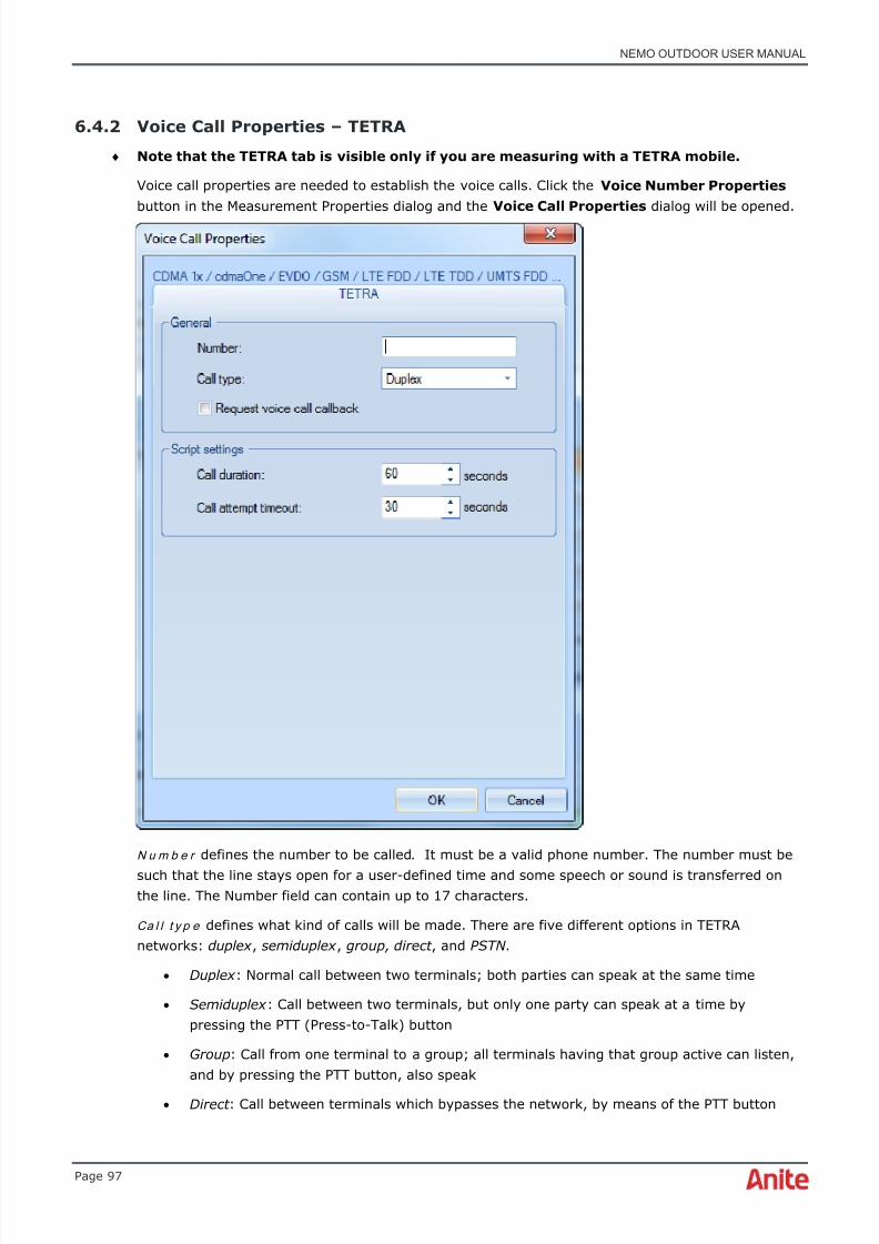
8/16/2019 Nemo Outdoor User Manual
http://slidepdf.com/reader/full/nemo-outdoor-user-manual 97/391
NEMO OUTDOOR USER MANUAL
Page 97
6.4.2 Voice Call Properties – TETRA
♦ Note that the TETRA tab is visible only if you are measuring with a TETRA mobile.
Voice call properties are needed to establish the voice calls. Click the Voice Number Properties button in the Measurement Properties dialog and the Voice Call Properties dialog will be opened.
N u m b e r defines the number to be called. It must be a valid phone number. The number must be
such that the line stays open for a user-defined time and some speech or sound is transferred onthe line. The Number field can contain up to 17 characters.
Ca l l t y p e defines what kind of calls will be made. There are five different options in TETRAnetworks: duplex , semiduplex , group, direct , and PSTN .
• Duplex : Normal call between two terminals; both parties can speak at the same time
• Semiduplex : Call between two terminals, but only one party can speak at a time bypressing the PTT (Press-to-Talk) button
• Group : Call from one terminal to a group; all terminals having that group active can listen,and by pressing the PTT button, also speak
• Direct : Call between terminals which bypasses the network, by means of the PTT button

8/16/2019 Nemo Outdoor User Manual
http://slidepdf.com/reader/full/nemo-outdoor-user-manual 98/391
NEMO OUTDOOR USER MANUAL
Page 98
• PSTN : Call from terminal to fixed line or to another cellular mobile
♦ Note that the Script Settings table is activated only if you access this dialog through theScript Editor. See chapter Making script files for more information on making scripts.
Ca l l d u r a t i o n determines the time that the call lasts in seconds. The duration timer is started fromthe channel assignment. The range of duration values is from 1 to 1,000,000 seconds. Note thatthe maximum value of this parameter is the same as the value you have set as the DelayBetween Call Attempts parameter.
Ca l l a t t e m p t t i m e o u t value determines the maximum duration of the call attempt. If the callattempt timeout value is exceeded before the cellular system has assigned a traffic channel, the callattempt will be stopped and the attempt will be marked as a failure. The range of the Call AttemptTimeout values is from 5 to 60 seconds. The value is recommended to be at least 10 seconds.
6.4.3 Push-to-Talk (PTT) testing
Nemo Outdoor supports QChat (developed by Qualcomm) and Kodiak Push-to-Talk (PTT)technologies. QChat Push-to-Talk (PTT) calls must be performed using the keypad of the phonewhen used with Nemo Outdoor. Kodiak PTT calls can be made using UI commands in NemoOutdoor.
Normal call events and statistics are written when attempting or ending PTT calls. Different states ofPTT calls, such as idle, getting ready to receive, receiving, transmitting are written to VCHI event.Please see the file format specification for further information. RTP packets are recorded anddecoded with Nemo Outdoor. Qchat and Kodiak PTT are optional features in Nemo Outdoor andrequire a license option.
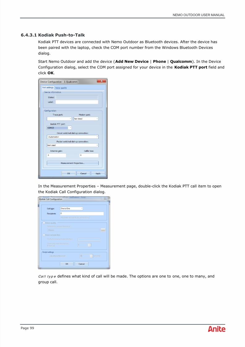
8/16/2019 Nemo Outdoor User Manual
http://slidepdf.com/reader/full/nemo-outdoor-user-manual 99/391
NEMO OUTDOOR USER MANUAL
Page 99
6.4.3.1 Kodiak Push-to-Talk
Kodiak PTT devices are connected with Nemo Outdoor as Bluetooth devices. After the device hasbeen paired with the laptop, check the COM port number from the Windows Bluetooth Devicesdialog.
Start Nemo Outdoor and add the device ( Add New Device | Phone | Qualcomm ). In the DeviceConfiguration dialog, select the COM port assigned for your device in the Kodiak PTT port field andclick OK .
In the Measurement Properties – Measurement page, double-click the Kodiak PTT call item to openthe Kodiak Call Configuration dialog.
Ca l l t y p e defines what kind of call will be made. The options are one to one, one to many, andgroup call.

8/16/2019 Nemo Outdoor User Manual
http://slidepdf.com/reader/full/nemo-outdoor-user-manual 100/391
NEMO OUTDOOR USER MANUAL
Page 100
R e c i p i e n t s defines to whom the call is made. The recipients are selected from the contact list ofthe Kodiak application and are defined as index numbers. For example, if you would like to make acall to the first contact on the contact list, enter 0. If the selected call type is one to many , defineseveral recipients and separate the index numbers with semicolons. If the selected call type isgroup call , select the recipient from the group contact list of the Kodiak application and again, usethe index number.
After the call type and recipients have been defined, select Register Kodiak Server to login to theKodiak server.
After you have registered to the Kodiak server you can start a Kodiak call.
Once the Kodiak call has been established, select Press PTT Button/Release PTT Button .
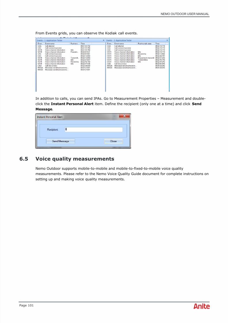
8/16/2019 Nemo Outdoor User Manual
http://slidepdf.com/reader/full/nemo-outdoor-user-manual 101/391
NEMO OUTDOOR USER MANUAL
Page 101
From Events grids, you can observe the Kodiak call events.
In addition to calls, you can send IPAs. Go to Measurement Properties – Measurement and double-click the Instant Personal Alert item. Define the recipient (only one at a time) and click SendMessage .
6.5 Voice quality measurements
Nemo Outdoor supports mobile-to-mobile and mobile-to-fixed-to-mobile voice qualitymeasurements. Please refer to the Nemo Voice Quality Guide document for complete instructions onsetting up and making voice quality measurements.
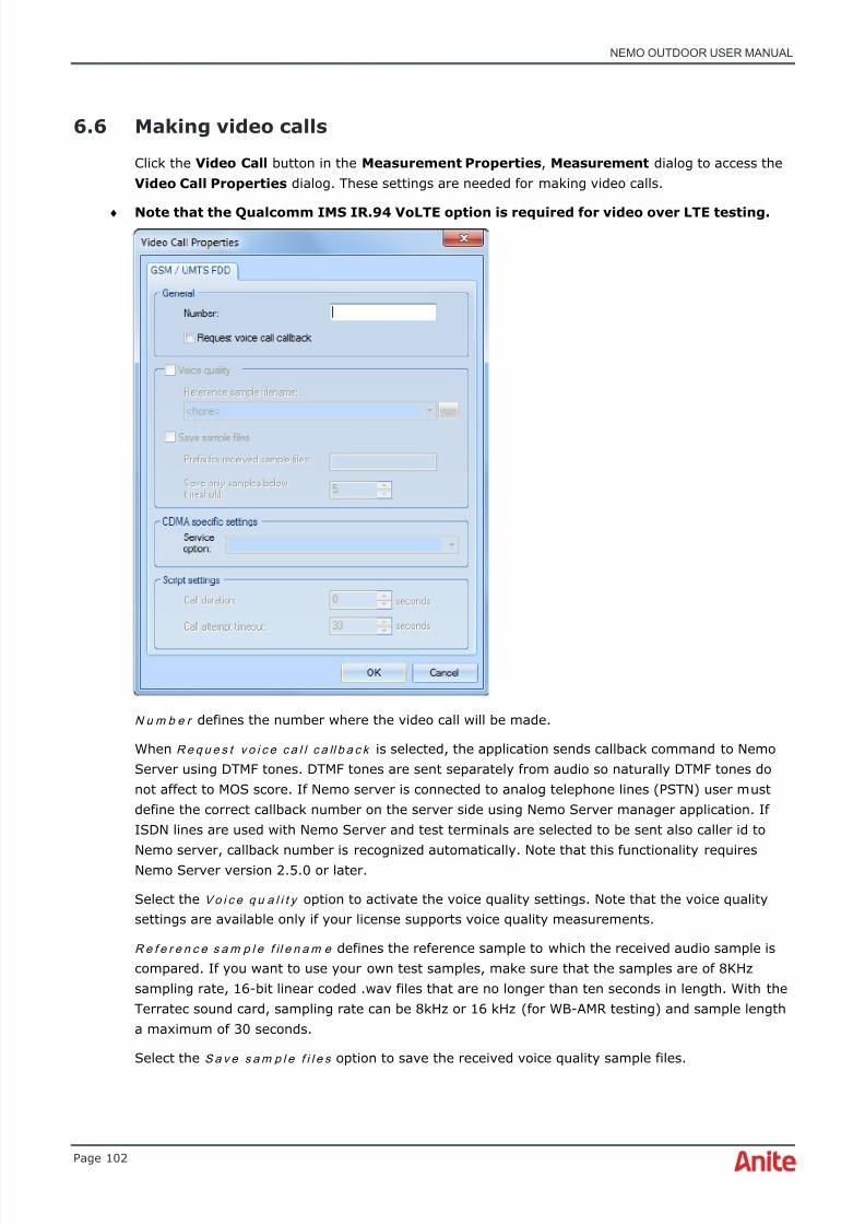
8/16/2019 Nemo Outdoor User Manual
http://slidepdf.com/reader/full/nemo-outdoor-user-manual 102/391
NEMO OUTDOOR USER MANUAL
Page 102
6.6 Making video calls
Click the Video Call button in the Measurement Properties , Measurement dialog to access theVideo Call Properties dialog. These settings are needed for making video calls.
♦ Note that the Qualcomm IMS IR.94 VoLTE option is required for video over LTE testing.
N u m b e r defines the number where the video call will be made.
When R e q u e s t v o i c e c a l l c a ll b a c k is selected, the application sends callback command to NemoServer using DTMF tones. DTMF tones are sent separately from audio so naturally DTMF tones donot affect to MOS score. If Nemo server is connected to analog telephone lines (PSTN) user mustdefine the correct callback number on the server side using Nemo Server manager application. IfISDN lines are used with Nemo Server and test terminals are selected to be sent also caller id toNemo server, callback number is recognized automatically. Note that this functionality requiresNemo Server version 2.5.0 or later.
Select the Vo i c e q u a l i t y option to activate the voice quality settings. Note that the voice qualitysettings are available only if your license supports voice quality measurements.
R e f e r e n c e s a m p l e f il e n a m e defines the reference sample to which the received audio sample iscompared. If you want to use your own test samples, make sure that the samples are of 8KHzsampling rate, 16-bit linear coded .wav files that are no longer than ten seconds in length. With theTerratec sound card, sampling rate can be 8kHz or 16 kHz (for WB-AMR testing) and sample lengtha maximum of 30 seconds.
Select the S a v e s a m p l e f i l e s option to save the received voice quality sample files.
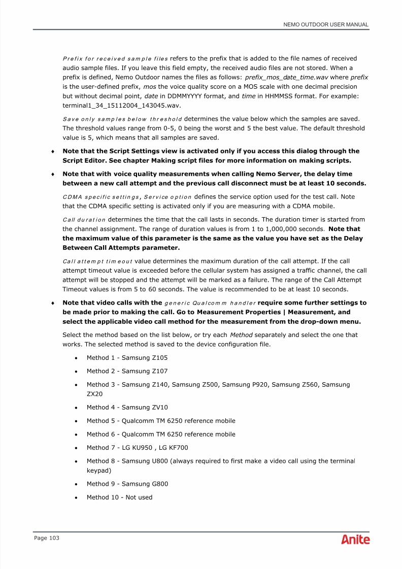
8/16/2019 Nemo Outdoor User Manual
http://slidepdf.com/reader/full/nemo-outdoor-user-manual 103/391
NEMO OUTDOOR USER MANUAL
Page 103
P r e f i x f o r r e c e i v e d s a m p l e f i le s refers to the prefix that is added to the file names of receivedaudio sample files. If you leave this field empty, the received audio files are not stored. When aprefix is defined, Nemo Outdoor names the files as follows: prefix_mos_date_time.wav where prefixis the user-defined prefix, mos the voice quality score on a MOS scale with one decimal precisionbut without decimal point, date in DDMMYYYY format, and time in HHMMSS format. For example:terminal1_34_15112004_143045.wav.
S a v e o n l y s a m p l e s b e l o w t h r e s h o l d determines the value below which the samples are saved.The threshold values range from 0-5, 0 being the worst and 5 the best value. The default thresholdvalue is 5, which means that all samples are saved.
♦ Note that the Script Settings view is activated only if you access this dialog through theScript Editor. See chapter Making script files for more information on making scripts.
♦ Note that with voice quality measurements when calling Nemo Server, the delay timebetween a new call attempt and the previous call disconnect must be at least 10 seconds.
C D M A s p e c i f i c s e t t i n g s , S e r v i ce o p t i o n defines the service option used for the test call. Notethat the CDMA specific setting is activated only if you are measuring with a CDMA mobile.
C a ll d u r a t i o n determines the time that the call lasts in seconds. The duration timer is started fromthe channel assignment. The range of duration values is from 1 to 1,000,000 seconds. Note thatthe maximum value of this parameter is the same as the value you have set as the DelayBetween Call Attempts parameter.
Ca l l a t t e m p t t i m e o u t value determines the maximum duration of the call attempt. If the callattempt timeout value is exceeded before the cellular system has assigned a traffic channel, the callattempt will be stopped and the attempt will be marked as a failure. The range of the Call AttemptTimeout values is from 5 to 60 seconds. The value is recommended to be at least 10 seconds.
♦ Note that video calls with the g e n e r i c Qu a l co m m h a n d l e r require some further settings tobe made prior to making the call. Go to Measurement Properties | Measurement, andselect the applicable video call method for the measurement from the drop-down menu.
Select the method based on the list below, or try each Method separately and select the one thatworks. The selected method is saved to the device configuration file.
• Method 1 - Samsung Z105
• Method 2 - Samsung Z107
• Method 3 - Samsung Z140, Samsung Z500, Samsung P920, Samsung Z560, SamsungZX20
• Method 4 - Samsung ZV10
• Method 5 - Qualcomm TM 6250 reference mobile
• Method 6 - Qualcomm TM 6250 reference mobile
• Method 7 - LG KU950 , LG KF700
• Method 8 - Samsung U800 (always required to first make a video call using the terminalkeypad)
• Method 9 - Samsung G800
• Method 10 - Not used
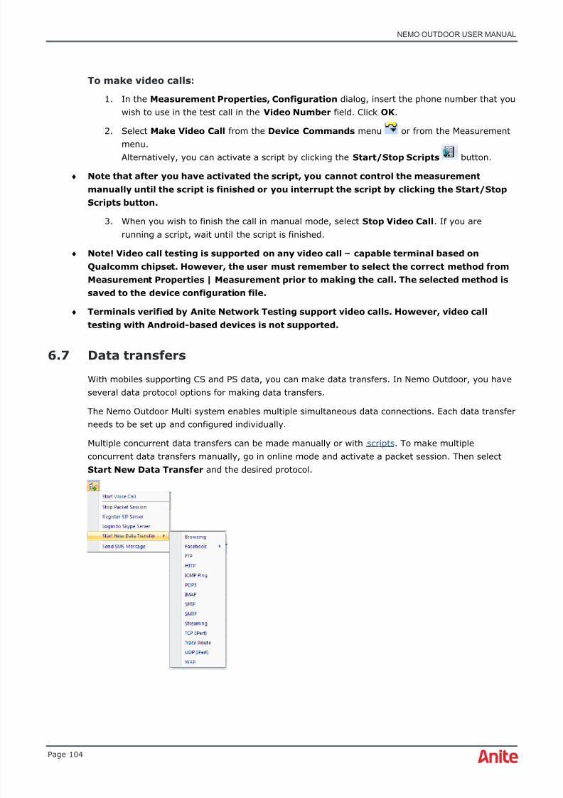
8/16/2019 Nemo Outdoor User Manual
http://slidepdf.com/reader/full/nemo-outdoor-user-manual 104/391
NEMO OUTDOOR USER MANUAL
Page 104
To make video calls:
1. In the Measurement Properties, Configuration dialog, insert the phone number that youwish to use in the test call in the Video Number field. Click OK .
2. Select Make Video Call from the Device Commands menu or from the Measurementmenu.Alternatively, you can activate a script by clicking the Start/Stop Scripts button.
♦ Note that after you have activated the script, you cannot control the measurementmanually until the script is finished or you interrupt the script by clicking the Start/StopScripts button.
3. When you wish to finish the call in manual mode, select Stop Video Call . If you arerunning a script, wait until the script is finished.
♦ Note! Video call testing is supported on any video call – capable terminal based onQualcomm chipset. However, the user must remember to select the correct method from
Measurement Properties | Measurement prior to making the call. The selected method issaved to the device configuration file.
♦ Terminals verified by Anite Network Testing support video calls. However, video calltesting with Android-based devices is not supported.
6.7 Data transfers
With mobiles supporting CS and PS data, you can make data transfers. In Nemo Outdoor, you haveseveral data protocol options for making data transfers.
The Nemo Outdoor Multi system enables multiple simultaneous data connections. Each data transferneeds to be set up and configured individually.
Multiple concurrent data transfers can be made manually or with scripts . To make multipleconcurrent data transfers manually, go in online mode and activate a packet session. Then selectStart New Data Transfer and the desired protocol.

8/16/2019 Nemo Outdoor User Manual
http://slidepdf.com/reader/full/nemo-outdoor-user-manual 105/391
NEMO OUTDOOR USER MANUAL
Page 105
♦ To view data in Packet decoder grids during playback, you need to enable the packetdecoding function (Measurement Properties - Measurement) prior to performing datameasurements. Select Full or Partial in the Enable IP Capture field. A separate .pcap-filewill be generated for the measurement, and this file needs to accompany themeasurement file under the same folder when viewing and decoding packet captureinformation in Packet Decoder grids in Nemo Outdoor.
6.7.1 Configuring the data connection
♦ Before you can start making data transfers you need to define the actual connection thatis used for the transfer. The setup is different for CS and PS data transfers.
If you are making CS data transfers, see chapter Data Call Properties. If you are making PS datatransfers, see chapter Packet Session Settings.
6.7.1.1 Data Call Properties dialog
Data Call properties are needed to establish the circuit-switched data connection. Open the DataCall Properties dialog by double-clicking the Circuit-Switched Data Call item in the Devices view.
There are separate views for GSM, UMTS, and CDMA. The parameters are the same. The UMTS andCDMA views just have fewer parameters.
♦ A PPP compatible server is required for CS data testing. Settings related to the server(number, username, and password) are operator-specific.
N u m b e r defines the number of the server.
U s e r n a m e refers to the server username.
P as sw o r d refers to the server password.
T r a n sp a r e n t m o d e defines whether transparent or non-transparent mode is used in the CS datacall.
Co m p r e s s i o n defines if no compression or v.42bis compression is used.

8/16/2019 Nemo Outdoor User Manual
http://slidepdf.com/reader/full/nemo-outdoor-user-manual 106/391
NEMO OUTDOOR USER MANUAL
Page 106
M o d e m t y p e refers to the modem type that the server is using. The alternatives are Analog (v.34)and ISDN (v.110 and v.120).
T im e s l o t s ( U L / D L ) defines the number of timeslots for each direction.
C o d i n g defines the coding scheme used in the air interface.
En a b l e a u t o m a t i c l i n k a d a p t a t i o n option allows you to disable and enable Automatic LinkAdaptation (ALA). The ALA technology controls power levels and automatically selects the bestchannel coding.
6.7.1.2 Packet session settings
Packet session settings are needed to establish the packet switched data connection. Double-clickthe Packet Session item in the Devices view to access the Packet Session Settings dialog.
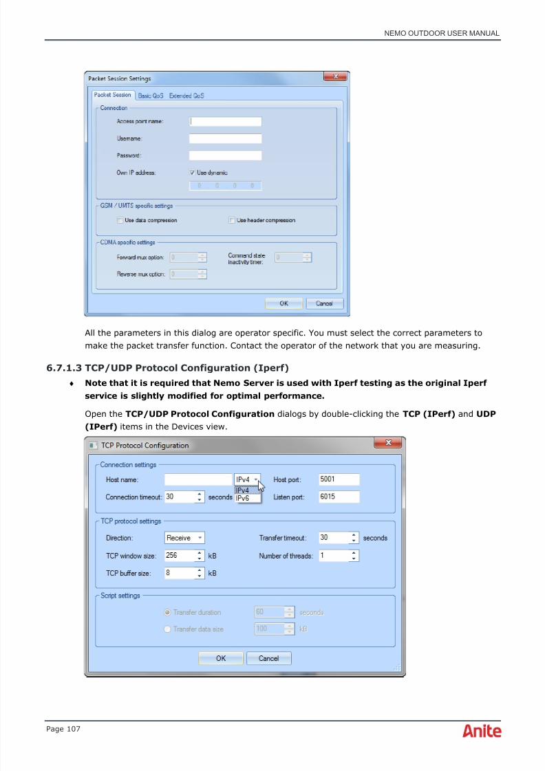
8/16/2019 Nemo Outdoor User Manual
http://slidepdf.com/reader/full/nemo-outdoor-user-manual 107/391
NEMO OUTDOOR USER MANUAL
Page 107
All the parameters in this dialog are operator specific. You must select the correct parameters tomake the packet transfer function. Contact the operator of the network that you are measuring.
6.7.1.3 TCP/UDP Protocol Configuration (Iperf)♦ Note that it is required that Nemo Server is used with Iperf testing as the original Iperf
service is slightly modified for optimal performance.
Open the TCP/UDP Protocol Configuration dialogs by double-clicking the TCP (IPerf) and UDP(IPerf) items in the Devices view.

8/16/2019 Nemo Outdoor User Manual
http://slidepdf.com/reader/full/nemo-outdoor-user-manual 108/391
NEMO OUTDOOR USER MANUAL
Page 108
H o s t n a m e is the IP address used in Nemo Server. You can also choose to use IPv6 tunneling overan IPv4 connection.
♦ Note that if you have multiple simultaneous data connections on different terminals, eachconnection must have its own IP address.
♦ Note that if you are doing multiple simultaneous data transfers on a single terminal, thesame IP address can be used.
♦ Note that Firewall should be turned off.
H o s t p o r t refers to the port used by Nemo Server. For TCP and UDP protocols, the default port is5001.
Co n n e c t i o n t i m e o u t defines the time in seconds for how long Nemo Outdoor waits for theconnection to be established. If a connection is not established within the defined time, connectionattempt will fail.
L is t e n p o r t refers to the port used by the client. For TCP and UDP protocols, the default port is6015.
D i r e c t i o n defines whether you are sending or receiving data, or both.
T r a n sf e r t i m e o u t determines the maximum waiting time after data connection. If the transferattempt timeout value is exceeded before data connection, the data connection attempt will bestopped and the attempt will be marked as a failure. The range of Transfer timeout values is from 0to 60 seconds. The value is recommended to be at least 10 seconds.
T CP w i n d o w s i ze defines the size of the receive window during TCP/IP transmission. If it is toosmall, it can decrease the maximum data throughput, and if it is too high it can increase theretransmission round-trip time (RTT). To be able to avoid decrease of data throughput, the window
size should be at least the maximum throughput multiplied by RTT. For example, with HSDPA withcategory 8 the maximum throughput is about 7.3 Mbit/s and RTT is about 100 ms. To avoidreduction of the throughput the TCP window size should be set at least to 7.3 Mbit/s * 0.1 s = 730kbit = 91.25 kB.
Downlink testing (these values are indicative only):
Max. throughput ~RTT (ms) TCP window size(kbit)
TCP window size (kB)
64 kbps (GPRS/EDGE)
600 38.4 4.8
128 kbps (GPRS/EDGE)
600 76.8 9.6
256 kbps (GPRS/EDGE)
600 153.6 19.2
384kbps (Rel. 99) 200 76.8 9.6
HSDPA 1.8MbpsUE category 3 & 4
100 180 22.5
HSDPA 3.6MbpsUE category 5 & 6
100 360 45
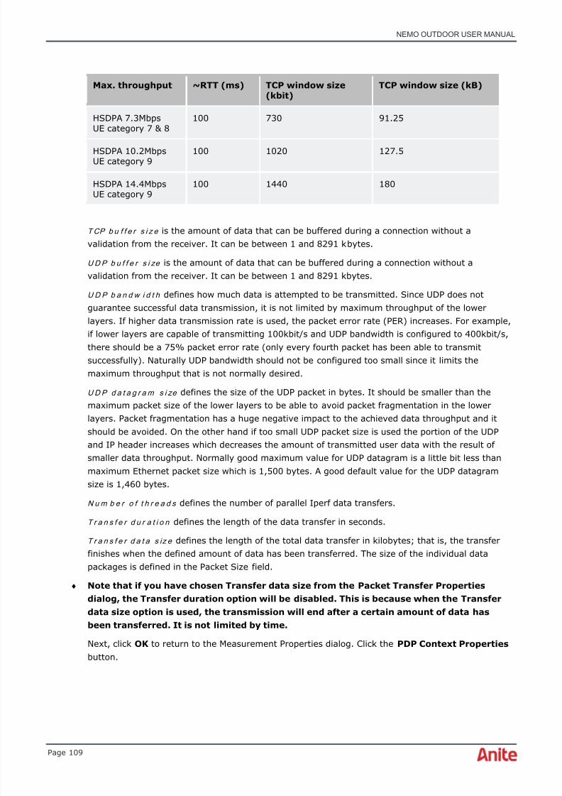
8/16/2019 Nemo Outdoor User Manual
http://slidepdf.com/reader/full/nemo-outdoor-user-manual 109/391
NEMO OUTDOOR USER MANUAL
Page 109
Max. throughput ~RTT (ms) TCP window size(kbit)
TCP window size (kB)
HSDPA 7.3MbpsUE category 7 & 8
100 730 91.25
HSDPA 10.2MbpsUE category 9
100 1020 127.5
HSDPA 14.4MbpsUE category 9
100 1440 180
T CP b u f f e r s i z e is the amount of data that can be buffered during a connection without avalidation from the receiver. It can be between 1 and 8291 kbytes.
U D P b u f f e r s i ze is the amount of data that can be buffered during a connection without a
validation from the receiver. It can be between 1 and 8291 kbytes.U D P b a n d w i d t h defines how much data is attempted to be transmitted. Since UDP does notguarantee successful data transmission, it is not limited by maximum throughput of the lowerlayers. If higher data transmission rate is used, the packet error rate (PER) increases. For example,if lower layers are capable of transmitting 100kbit/s and UDP bandwidth is configured to 400kbit/s,there should be a 75% packet error rate (only every fourth packet has been able to transmitsuccessfully). Naturally UDP bandwidth should not be configured too small since it limits themaximum throughput that is not normally desired.
U D P d a t a g r a m s i ze defines the size of the UDP packet in bytes. It should be smaller than themaximum packet size of the lower layers to be able to avoid packet fragmentation in the lower
layers. Packet fragmentation has a huge negative impact to the achieved data throughput and itshould be avoided. On the other hand if too small UDP packet size is used the portion of the UDPand IP header increases which decreases the amount of transmitted user data with the result ofsmaller data throughput. Normally good maximum value for UDP datagram is a little bit less thanmaximum Ethernet packet size which is 1,500 bytes. A good default value for the UDP datagramsize is 1,460 bytes.
N u m b e r o f t h r e a d s defines the number of parallel Iperf data transfers.
T r a n s f e r d u r a t i o n defines the length of the data transfer in seconds.
T r a n s f e r d a t a s iz e defines the length of the total data transfer in kilobytes; that is, the transfer
finishes when the defined amount of data has been transferred. The size of the individual datapackages is defined in the Packet Size field.
♦ Note that if you have chosen Transfer data size from the Packet Transfer Propertiesdialog, the Transfer duration option will be disabled. This is because when the Transferdata size option is used, the transmission will end after a certain amount of data hasbeen transferred. It is not limited by time.
Next, click OK to return to the Measurement Properties dialog. Click the PDP Context Properties button.
8/16/2019 Nemo Outdoor User Manual
http://slidepdf.com/reader/full/nemo-outdoor-user-manual 110/391
NEMO OUTDOOR USER MANUAL
Page 110
6.7.2 Configuring the FTP protocol
Nemo Outdoor has an integrated FTP client , which can be used to measure data transfer ratesbetween Nemo Outdoor and the FTP server. The server can be any standard FTP server. Currentdata throughput and transferred data size are reported during transfer. The FTP module supports
firewall-friendly passive mode transfers. Normally when a data transfer is initialized, the serveropens a new connection to the client and then data is transferred through this connection. Somefirewalls may be configured to refuse any incoming connection requests, and in that case the datatransfer would fail. With passive mode, the client always opens those new connections so thefirewall does not block the connection.
♦ A PPP compatible server is required for CS data testing. Settings related to the server(number, username, and password) are operator-specific.
♦ If you encounter problems with the data transfer, deactivate the firewall on the computerwhere you are running Nemo Outdoor.
To set up data measurements using FTP:1. Follow the instructions in the Device Configuration Guide to configure the measurement
devices.
2. Define measurement-related settings in the Measurement Properties dialog (seeMeasurement Properties – Measurement)
3. Configure the data connection for CS data (see Data Call Properties) or PS data (see Packetsession settings) .
4. Define FTP transfer-related settings in the FTP Transfer Properties dialog.
5. Create a script (optional) (see Making script files) .
6. After you have completed the setup, you can start the actual data transfer (see Making datatransfers) .

8/16/2019 Nemo Outdoor User Manual
http://slidepdf.com/reader/full/nemo-outdoor-user-manual 111/391
NEMO OUTDOOR USER MANUAL
Page 111
6.7.2.1 FTP Transfer Properties dialog
Open the FTP Transfer Properties dialog by double-clicking the FTP item in the Devices view.
H o st n a m e is the IP address of the FTP server used. You can also choose to use IPv6 tunnelingover an IPv4 connection.
♦ Note that if you have multiple simultaneous data connections on different terminalswithout NMR, each connection must have its own IP address.
♦ Note that if you are doing multiple simultaneous data transfers on a single terminal, thesame IP address can be used.
♦ If you encounter problems with the data transfer, deactivate the firewall on the computer
on which you are running Nemo Outdoor.P o r t refers to the port used by the FTP server.
In the U s er n a m e field you must enter a valid username for the FTP server.
In the P a ss w o r d field you must enter a valid password for the FTP server.
Some firewalls may be configured to refuse any incoming connection requests, and in that case thedata transfer would fail. With passive mode, the client always opens those new connections so thefirewall does not block the connection. Select the P a ss i v e m o d e option to activate passive mode.
Co n n e c t i o n t i m e o u t defines the time in seconds for how long Nemo Outdoor waits for theconnection to be established. If a connection is not established within the defined time, connectionattempt will fail.

8/16/2019 Nemo Outdoor User Manual
http://slidepdf.com/reader/full/nemo-outdoor-user-manual 112/391
NEMO OUTDOOR USER MANUAL
Page 112
P r o x y t y p e defines the type of the proxy used in the measurements. Supported types areTunneling, SOCKS4, and SOCKS5.
A d d r e s s refers to the address of the proxy.
P o r t refers to the port used by the proxy.
In the U s er n a m e field you must enter a valid username for the proxy.
In the P a ss w o r d field you must enter a valid password for the proxy.
D i r e c t i o n defines whether you are sending or receiving data.
B u f f e r s i z e defines the transmit/receive buffer used with the transfer protocol in kilobytes.
T r a n sf e r t i m e o u t defines the time in seconds for how long Nemo Outdoor waits during a transfer ifthere is a break in the data flow. If the transfer does not continue within the defined time, transferwill fail.
T r a n sf e r a t t e m p t s defines how many times an interrupted data transfer is resumed during oneFTP session.
N u m b e r o f t h r e a d s defines in how many threads the test file is split during an FTP transfer. Forexample, the size of the downloaded file is 10MB. The number of threads is set to five. NemoOutdoor splits the 10MB file into five fragments with the size of 2MB each. All five FTP transfersessions are started simultaneously. Each thread creates a new FTP session and transfers afragment of the file. Total application data throughput is recorded including all threads. Resume isnot supported with multi threaded FTP transfers. In case of a data drop, all threads will start fromthe beginning.
R e m o t e f i le defines the name and location of the file that is on the FTP server. If you are receiving
data, this is the source file. If you are sending data, this is the destination file.♦ Note that if you have multiple simultaneous data connections and the direction is set to
send for all of them, you must define a different remote file for each connection.Otherwise the different data connections will try to write in the same file.
♦ Also note that if there are several testing units using the same FTP server, werecommend that you use a unique file name extension (e.g., filename_tester1.txt,filename_tester2.txt, etc.) for each unit to avoid a situation where two testing units aretrying to write in the same file.
L o c a l f i l e defines the name and location of the file that is on your laptop. If you are receiving data,this is the output file. If you are sending data, this is the source file. The default location for thesefiles is defined in the User Interface Properties – Paths dialog.
G e n e r a t e l o c a l f i le allows you to generate random binary files with user-specified file size. Thisfunctionality is available with FTP upload testing. The file is named with following format<IMEI>_<file size in kB>.bin.
Select the W r i t e l o c a l f il e t o d i s k option to save the downloaded file on disk.
♦ Note that if you have multiple simultaneous data connections and the direction is set toreceive for all of them, you must define a different local file for each connection.Otherwise the different data connections will try to write in the same file.

8/16/2019 Nemo Outdoor User Manual
http://slidepdf.com/reader/full/nemo-outdoor-user-manual 113/391
NEMO OUTDOOR USER MANUAL
Page 113
6.7.3 Configuring the SFTP protocol
Nemo Outdoor has an integrated SFTP client , which can be used to measure data transfer ratesbetween Nemo Outdoor and the SFTP server. The server can be any standard SFTP server. Currentdata throughput and transferred data size are reported during transfer. The SFTP module supports
firewall-friendly passive mode transfers. Normally when a data transfer is initialized, the serveropens a new connection to the client and then data is transferred through this connection. Somefirewalls may be configured to refuse any incoming connection requests, and in that case the datatransfer would fail. With passive mode, the client always opens those new connections so thefirewall does not block the connection.
♦ A PPP compatible server is required for CS data testing. Settings related to the server(number, username, and password) are operator-specific.
♦ If you encounter problems with the data transfer, deactivate the firewall on the computerwhere you are running Nemo Outdoor.
To set up data measurements using SFTP:1. Follow the instructions in the Device Configuration Guide to connect and configure the
measurement devices.
2. Define measurement-related settings in the Measurement Properties dialog (seeMeasurement Properties – Measurement)
3. Configure the data connection for CS data (see Data Call Properties) or PS data (see Packetsession settings) .
4. Define SFTP transfer-related settings in the SFTP Transfer Properties dialog.
5. Create a script (optional) (see Making script files) .
6. After you have completed the setup, you can start the actual data transfer (see Making datatransfers) .

8/16/2019 Nemo Outdoor User Manual
http://slidepdf.com/reader/full/nemo-outdoor-user-manual 114/391
8/16/2019 Nemo Outdoor User Manual
http://slidepdf.com/reader/full/nemo-outdoor-user-manual 115/391
NEMO OUTDOOR USER MANUAL
Page 115
P o r t refers to the port used by the proxy.
In the U s er n a m e field you must enter a valid username for the proxy.
In the P a ss w o r d field you must enter a valid password for the proxy.
D i r e c t i o n defines whether you are sending or receiving data.B u f f e r s i z e defines the transmit/receive buffer used with the transfer protocol in kilobytes.
T r a n sf e r t i m e o u t defines the time in seconds for how long Nemo Outdoor waits during a transfer ifthere is a break in the data flow. If the transfer does not continue within the defined time, transferwill fail.
T r a n sf e r a t t e m p t s defines how many times an interrupted data transfer is resumed during oneSFTP session.
R e m o t e f i le defines the name and location of the file that is on the SFTP server. If you arereceiving data, this is the source file. If you are sending data, this is the destination file.
♦ Note that if you have multiple simultaneous data connections and the direction is set tosend for all of them, you must define a different remote file for each connection.Otherwise the different data connections will try to write in the same file.
♦ Also note that if there are several testing units using the same SFTP server, werecommend that you use a unique file name extension (e.g., filename_tester1.txt,filename_tester2.txt, etc.) for each unit to avoid a situation where two testing units aretrying to write in the same file.
Local file defines the name and location of the file that is on your laptop. If you are receiving data,this is the output file. If you are sending data, this is the source file. The default location for these
files is defined in the User Interface Properties – Paths dialog.G e n e r a t e l o c a l f i le allows you to generate random binary files with user-specified file size. Thisfunctionality is available with SFTP upload testing. The file is named with following format<IMEI>_<file size in kB>.bin.
Select the W r i t e l o c a l f il e t o d i s k option to save the downloaded file on disk.
♦ Note that if you have multiple simultaneous data connections and the direction is set toreceive for all of them, you must define a different local file for each connection.Otherwise the different data connections will try to write in the same file.
6.7.4 Configuring the HTTP(S) protocol
The HTTP(S) testing functionality offers the possibility to test how data is transferred through theHTTP(S) protocol. The HTTP(S) protocol is used in web browsing. In HTTP(S) testing, the userselects one file that will be downloaded or uploaded through the HTTP(S) protocol and this datatransfer is measured.
♦ A PPP compatible server is required for CS data testing. Settings related to the server(number, username, and password) are operator-specific.
To set up data measurements using HTTP(S):
1. Follow the instructions in the Device Configuration Guide to connect and configure the
measurement devices.

8/16/2019 Nemo Outdoor User Manual
http://slidepdf.com/reader/full/nemo-outdoor-user-manual 116/391
NEMO OUTDOOR USER MANUAL
Page 116
2. Define measurement-related settings in the Measurement Properties dialog (seeMeasurement Properties – Measurement)
3. Configure the data connection for CS data (see Data Call Properties) or PS data (see Packetsession settings) .
4. Define HTTP transfer-related settings in the HTTP(S) Transfer Properties dialog.
5. Create a script (optional) (see Making script files) .
6. After you have completed the setup, you can start the actual data transfer (see Making datatransfers) .
6.7.4.1 HTTP(S) Transfer Properties dialog
Open the HTTP Transfer Properties dialog by double-clicking the HTTP item in the Devices view.The same dialog is used for defining HTTPS transfer properties.
In the HTTP Transfer Properties dialog, you can define the required data transfer settings.
P r o x y Ty p e defines the type of the proxy used in the measurements. Supported types areTunneling, SOCKS4, and SOCKS5.
A d d r e s s refers to the address of the proxy.
P o r t refers to the port used by the proxy.
8/16/2019 Nemo Outdoor User Manual
http://slidepdf.com/reader/full/nemo-outdoor-user-manual 117/391
NEMO OUTDOOR USER MANUAL
Page 117
Co n n e c t i o n t i m e o u t defines the time in seconds for how long Nemo Outdoor waits for theconnection to be established. If a connection is not established within the defined time, connectionattempt will fail.
In the U s er n a m e field you must enter a valid username for the proxy.
In the P a ss w o r d field you must enter a valid password for the proxy.
Select the appropriate A u t h e n t i c a t io n S ch e m e and define the username and password for theauthentication.
D i r e c t i o n defines whether the HTTP file is sent or received. For sending, there are two options:POST and PUT.
B u f f e r s i z e defines the transmit/receive buffer used with the transfer protocol in kilobytes.
T r a n sf e r t i m e o u t defines the time in seconds for how long Nemo Outdoor waits during a transfer ifthere is a break in the data flow. If the transfer does not continue within the defined time, transferwill fail.
N u m b e r o f t h r e a d s enables all the threads to be started simultaneously with the same timestamp. The number of threads can be defined by the user. Each thread transfers the entire file.
U R L defines the IP address of the test file that will be downloaded when data is received. Forexample, http://www.yourcompany.com/testfile.htm . Only one file will be downloaded at a time. Ifyou are sending HTTP data, URL defines the destination. To define a port for the transfer, type theport number after the URL, for example, http://www.yourcompany.com:85.
♦ Note that if you have multiple simultaneous data connections on different terminalswithout NMR, you must define a different URL from different servers for each of them.
♦ Note that if you have multiple simultaneous data connections on a single terminal, youcan use the same URL for all of them.
♦ If you encounter problems with the data transfer, deactivate the firewall on the computerwhere you are running Nemo Outdoor.
To make consecutive transfers, create a script with several HTTP transfers. See chapter Makingscript files for instructions on making scripts.
L o c a l F i l e defines the output file and location for HTTP testing. The default location for these files isdefined in the User Interface Properties – Paths dialog.
♦ Note that if you have multiple simultaneous data connections and the direction is set to
receive for all of them, you must define a different local file for each connection.Otherwise the different data connections will try to write in the same file.
G e n e r a t e l o c a l f i le allows you to generate random binary files with user-specified file size. Thisfunctionality is available with HTTP upload testing. The file is named with following format<IMEI>_<file size in kB>.bin.
Select the W r i t e l o c a l f il e t o d i s k option to save the downloaded file on disk.
U s e r a g e n t allows you to define the user agent string used for the HTTP/HTTPS transfer. It is bydefault Nemo Outdoor, but it is possible to define another user agent. Please see the http://user-agents.my-addr.com/user_agent_request/user_agent_examples-and-user_agent_types.php forfurther details about user agents.
Select the U s e SS L e n c r y p t i o n option to transfer the files over a HTTPS connection.

8/16/2019 Nemo Outdoor User Manual
http://slidepdf.com/reader/full/nemo-outdoor-user-manual 118/391
NEMO OUTDOOR USER MANUAL
Page 118
6.7.5 Configuring the (HTTP) browsing protocol
The HTTP Browser testing functionality offers the possibility to test how data is transferred throughthe HTTP Browsing protocol. The HTTP protocol is used in web browsing. In HTTP testing, the userselects one URL address that will be downloaded through the HTTP protocol and this data transfer is
measured.
♦ If you are experiencing problems with HTTP browsing testing, such as, the pagedownloading time is increased, disable the following LAN settings: Automatically detectsettings and Proxy server.
To set up data measurements using HTTP browsing protocol:
1. Follow the instructions in the Device Configuration Guide to connect and configure themeasurement devices.
2. Define measurement-related settings in the Measurement Properties dialog (seeMeasurement Properties – Measurement) .
3. Configure the data connection for CS data (see Data Call Properties) or PS data (see Packetsession settings) .
4. Define HTTP browsing-related settings in the Browser Transfer Properties dialog.
5. Create a script (optional) (see Making script files) .
6. After you have completed the setup, you can start the actual data transfer (see Making datatransfers) .
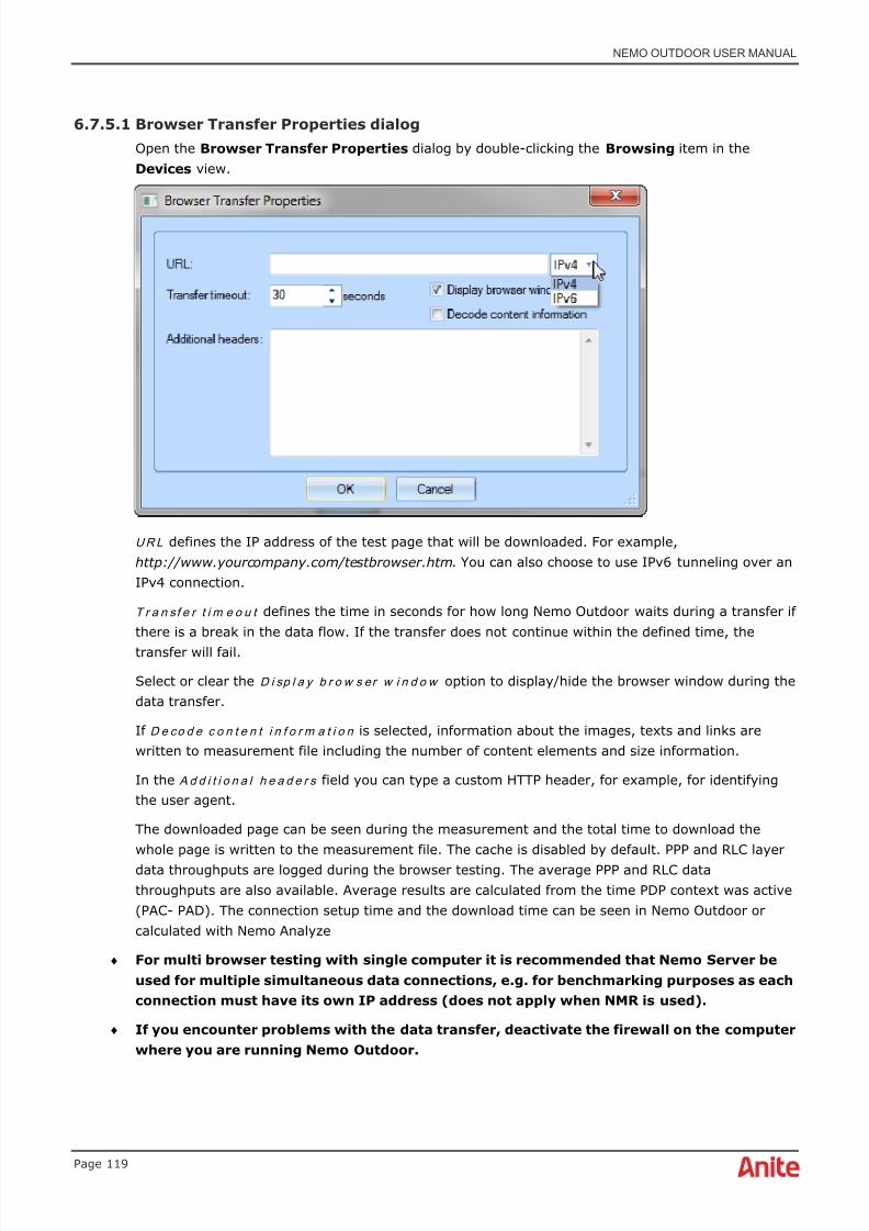
8/16/2019 Nemo Outdoor User Manual
http://slidepdf.com/reader/full/nemo-outdoor-user-manual 119/391
NEMO OUTDOOR USER MANUAL
Page 119
6.7.5.1 Browser Transfer Properties dialog
Open the Browser Transfer Properties dialog by double-clicking the Browsing item in theDevices view.
U R L defines the IP address of the test page that will be downloaded. For example,http://www.yourcompany.com/testbrowser.htm . You can also choose to use IPv6 tunneling over anIPv4 connection.
T r a n sf e r t i m e o u t defines the time in seconds for how long Nemo Outdoor waits during a transfer ifthere is a break in the data flow. If the transfer does not continue within the defined time, thetransfer will fail.
Select or clear the D i sp l a y b r o w s er w i n d o w option to display/hide the browser window during thedata transfer.
If D e co d e c o n t e n t i n f o r m a t i o n is selected, information about the images, texts and links arewritten to measurement file including the number of content elements and size information.
In the A d d i t i o n a l h e a d e r s field you can type a custom HTTP header, for example, for identifyingthe user agent.
The downloaded page can be seen during the measurement and the total time to download thewhole page is written to the measurement file. The cache is disabled by default. PPP and RLC layerdata throughputs are logged during the browser testing. The average PPP and RLC datathroughputs are also available. Average results are calculated from the time PDP context was active(PAC- PAD). The connection setup time and the download time can be seen in Nemo Outdoor orcalculated with Nemo Analyze
♦ For multi browser testing with single computer it is recommended that Nemo Server beused for multiple simultaneous data connections, e.g. for benchmarking purposes as eachconnection must have its own IP address (does not apply when NMR is used).
♦ If you encounter problems with the data transfer, deactivate the firewall on the computerwhere you are running Nemo Outdoor.
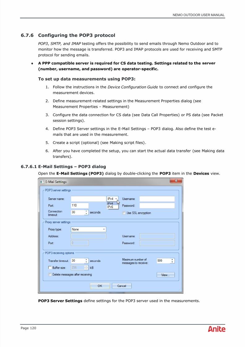
8/16/2019 Nemo Outdoor User Manual
http://slidepdf.com/reader/full/nemo-outdoor-user-manual 120/391
NEMO OUTDOOR USER MANUAL
Page 120
6.7.6 Configuring the POP3 protocol
POP3 , SMTP, and IMAP testing offers the possibility to send emails through Nemo Outdoor and tomonitor how the message is transferred. POP3 and IMAP protocols are used for receiving and SMTPprotocol for sending emails.
♦ A PPP compatible server is required for CS data testing. Settings related to the server(number, username, and password) are operator-specific.
To set up data measurements using POP3:
1. Follow the instructions in the Device Configuration Guide to connect and configure themeasurement devices.
2. Define measurement-related settings in the Measurement Properties dialog (seeMeasurement Properties – Measurement)
3. Configure the data connection for CS data (see Data Call Properties) or PS data (see Packet
session settings) .4. Define POP3 Server settings in the E-Mail Settings – POP3 dialog. Also define the test e-
mails that are used in the measurement.
5. Create a script (optional) (see Making script files) .
6. After you have completed the setup, you can start the actual data transfer (see Making datatransfers) .
6.7.6.1 E-Mail Settings – POP3 dialog
Open the E-Mail Settings (POP3) dialog by double-clicking the POP3 item in the Devices view.
POP3 Server Settings define settings for the POP3 server used in the measurements.

8/16/2019 Nemo Outdoor User Manual
http://slidepdf.com/reader/full/nemo-outdoor-user-manual 121/391
NEMO OUTDOOR USER MANUAL
Page 121
Se r v e r n a m e defines a name or an IP address for the POP3 server. You can also choose to useIPv6 tunneling over an IPv4 connection.
♦ Note that if you have multiple simultaneous data connections on different terminals, eachconnection must have its own IP address.
♦ Note that if you have multiple simultaneous data connections on a single terminal, thesame IP address can be used.
P o r t refers to the port used by the POP3 server.
In the U s er n a m e field you must enter a valid username for the POP3 server.
In the P a ss w o r d field you must enter a valid password for the POP3 server.
Select the U s e SS L e n c r y p t i o n option to apply SSL encryption to the test email.
Co n n e c t i o n t i m e o u t defines the time in seconds for how long Nemo Outdoor waits for theconnection to be established. If a connection is not established within the defined time, connection
attempt will fail.
Proxy server settings define settings for the proxy server used in the measurements.
P r o x y t y p e defines the type of the proxy used in the measurements. Supported types areTunneling, SOCKS4, and SOCKS5.
A d d r e s s refers to the address of the proxy.
P o r t refers to the port used by the proxy.
In the U s er n a m e field you must enter a valid username for the proxy.
In the P a ss w o r d field you must enter a valid password for the proxy.
POP3 receiving options define how the test e-mails are received and handled by Nemo Outdoor.
T r a n sf e r t i m e o u t defines the time in seconds for how long Nemo Outdoor waits during a transfer ifthere is a break in the data flow. If the transfer does not continue within the defined time, transferwill fail.
B u f f e r s i z e defines the transmit/receive buffer used with the transfer protocol in kilobytes.
M a x i m u m n u m b e r o f m e s s ag e s t o r e ce i v e defines the maximum number of messages receivedfrom the e-mail server.
Select the D e l e t e m e s sa g e s a f t e r r e c e i v i n g option to delete all received test e-mails. This willsave disk space.
The Vi e w button opens a received test message in the E-Mail Editor dialog.
6.7.7 Configuring the SMTP protocol
POP3 , SMTP, and IMAP testing offers the possibility to send emails through Nemo Outdoor and tomonitor how the message is transferred. POP3 and IMAP protocols are used for receiving and SMTPprotocol for sending emails.
♦ A PPP compatible server is required for CS data testing. Settings related to the server(number, username, and password) are operator-specific.
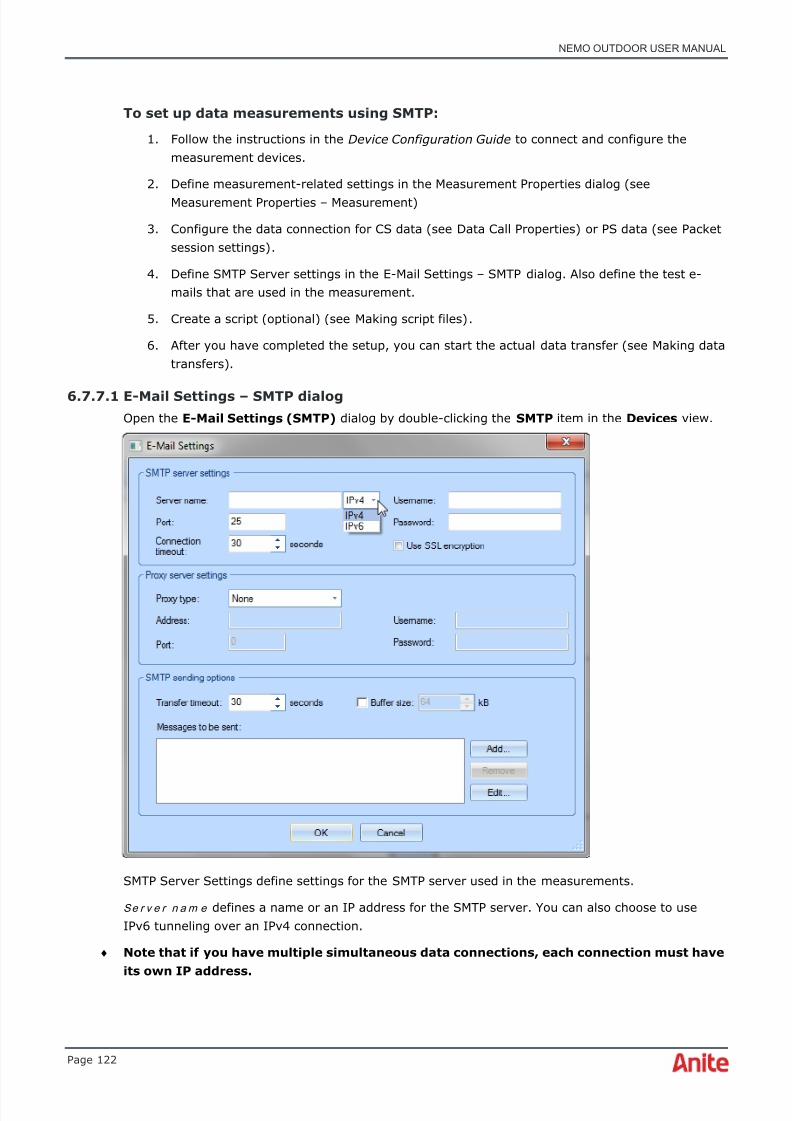
8/16/2019 Nemo Outdoor User Manual
http://slidepdf.com/reader/full/nemo-outdoor-user-manual 122/391

8/16/2019 Nemo Outdoor User Manual
http://slidepdf.com/reader/full/nemo-outdoor-user-manual 123/391
NEMO OUTDOOR USER MANUAL
Page 123
♦ Note that if you have multiple simultaneous data connections on a single terminal, thesame IP address can be used.
♦ Note that some operators prevent accessing SMTP services other than their own.Therefore, it is not possible to test SMTP against the Nemo server with those operators'
SIM cards.
P o r t refers to the port used by the SMTP server.
In the U s er n a m e field you must enter a valid username for the SMTP server.
In the P a ss w o r d field you must enter a valid password for the SMTP server.
Co n n e c t i o n t i m e o u t defines the time in seconds for how long Nemo Outdoor waits for theconnection to be established. If a connection is not established within the defined time, connectionattempt will fail.
Select the U s e SS L e n c r y p t i o n option to apply SSL encryption to the test email.
Proxy server settings define settings for the proxy server used in the measurements.
P r o x y t y p e defines the type of the proxy used in the measurements. Supported types areTunneling, SOCKS4, and SOCKS5.
A d d r e s s refers to the address of the proxy.
P o r t refers to the port used by the proxy.
In the U s er n a m e field you must enter a valid username for the proxy.
In the P a ss w o r d field you must enter a valid password for the proxy.
T r a n sf e r t i m e o u t defines the time in seconds for how long Nemo Outdoor waits during a transfer if
there is a break in the data flow. If the transfer does not continue within the defined time, transferwill fail.
B u f f e r s i z e defines the transmit/receive buffer used with the transfer protocol in kilobytes.
M e s s a g e s t o b e s e n t defines the test messages used in the SMTP test. Click the Edit button toopen the E-Mail Editor where you can type the test message and attach files to the message.
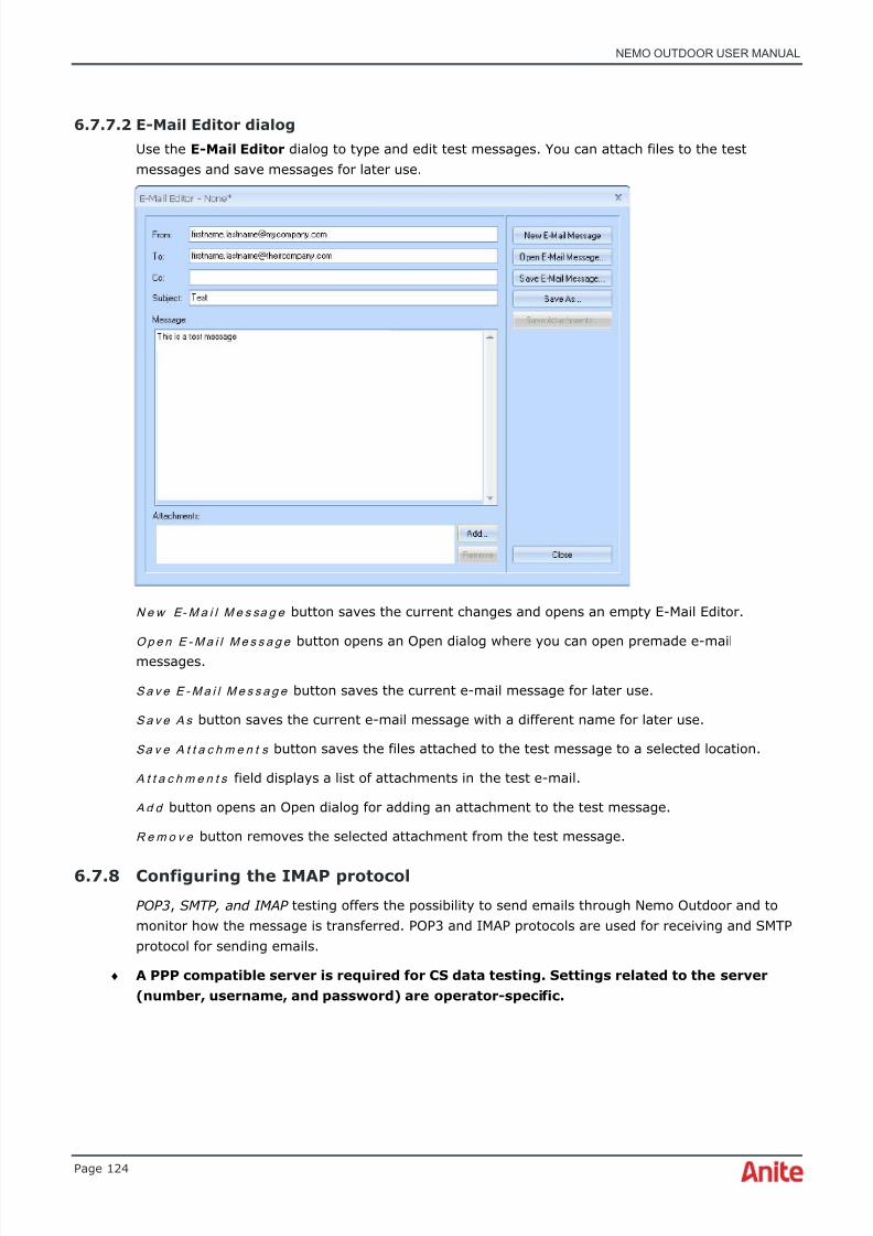
8/16/2019 Nemo Outdoor User Manual
http://slidepdf.com/reader/full/nemo-outdoor-user-manual 124/391
NEMO OUTDOOR USER MANUAL
Page 124
6.7.7.2 E-Mail Editor dialog
Use the E-Mail Editor dialog to type and edit test messages. You can attach files to the testmessages and save messages for later use.
N e w E- M a i l M e s sa g e button saves the current changes and opens an empty E-Mail Editor.
O p e n E - M a i l M e s s a g e button opens an Open dialog where you can open premade e-mailmessages.
S a v e E - M a i l M e s s a g e button saves the current e-mail message for later use.
S a v e A s button saves the current e-mail message with a different name for later use.
Sa v e A t t a c h m e n t s button saves the files attached to the test message to a selected location.
A t t a c h m e n t s field displays a list of attachments in the test e-mail.
A d d button opens an Open dialog for adding an attachment to the test message.
R e m o v e button removes the selected attachment from the test message.
6.7.8 Configuring the IMAP protocol
POP3 , SMTP, and IMAP testing offers the possibility to send emails through Nemo Outdoor and tomonitor how the message is transferred. POP3 and IMAP protocols are used for receiving and SMTPprotocol for sending emails.
♦ A PPP compatible server is required for CS data testing. Settings related to the server(number, username, and password) are operator-specific.
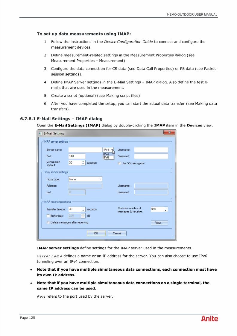
8/16/2019 Nemo Outdoor User Manual
http://slidepdf.com/reader/full/nemo-outdoor-user-manual 125/391
NEMO OUTDOOR USER MANUAL
Page 125
To set up data measurements using IMAP:
1. Follow the instructions in the Device Configuration Guide to connect and configure themeasurement devices.
2. Define measurement-related settings in the Measurement Properties dialog (seeMeasurement Properties – Measurement) .
3. Configure the data connection for CS data (see Data Call Properties) or PS data (see Packetsession settings) .
4. Define IMAP Server settings in the E-Mail Settings – IMAP dialog. Also define the test e-mails that are used in the measurement.
5. Create a script (optional) (see Making script files) .
6. After you have completed the setup, you can start the actual data transfer (see Making datatransfers) .
6.7.8.1 E-Mail Settings – IMAP dialogOpen the E-Mail Settings (IMAP) dialog by double-clicking the IMAP item in the Devices view.
IMAP server settings define settings for the IMAP server used in the measurements.
Se r v e r n a m e defines a name or an IP address for the server. You can also choose to use IPv6tunneling over an IPv4 connection.
♦ Note that if you have multiple simultaneous data connections, each connection must haveits own IP address.
♦ Note that if you have multiple simultaneous data connections on a single terminal, thesame IP address can be used.
P o r t refers to the port used by the server.

8/16/2019 Nemo Outdoor User Manual
http://slidepdf.com/reader/full/nemo-outdoor-user-manual 126/391
NEMO OUTDOOR USER MANUAL
Page 126
In the U s er n a m e field you must enter a valid username for the server.
In the P a ss w o r d field you must enter a valid password for the server.
Co n n e c t i o n t i m e o u t defines the time in seconds for how long Nemo Outdoor waits for theconnection to be established. If a connection is not established within the defined time, connectionattempt will fail.
Select the U s e SS L e n c r y p t i o n option to apply SSL encryption to the test email.
Proxy server settings define settings for the proxy server used in the measurements.
P r o x y t y p e defines the type of the proxy used in the measurements. Supported types areTunneling, SOCKS4, and SOCKS5.
A d d r e s s refers to the address of the proxy.
P o r t refers to the port used by the proxy.
In the U s er n a m e field you must enter a valid username for the proxy.
In the P a ss w o r d field you must enter a valid password for the proxy.
IMAP receiving options define how the test e-mails are received and handled by Nemo Outdoor.
T r a n sf e r t i m e o u t defines the time in seconds for how long Nemo Outdoor waits during a transfer ifthere is a break in the data flow. If the transfer does not continue within the defined time, transferwill fail.
B u f f e r s i z e defines the transmit/receive buffer used with the transfer protocol in kilobytes.
M a x i m u m n u m b e r o f m e s sa g e s t o r e ce i v e defines the maximum number of messages receivedfrom the e-mail server.
Select the D e l e t e m e s sa g e s a f t e r r e c e i v i n g option to delete all received test e-mails. This willsave disk space.
The Vi e w button opens a received test message in the E-Mail Editor dialog.
6.7.9 Configuring the WAP protocol
The WAP testing functionality offers the possibility to test how data is transferred through the WAPprotocol. The WAP protocol is used, for example, in web browsing. In the WAP testing, the userselects one file that will be downloaded through the WAP protocol and this data transfer ismeasured.
♦ A PPP compatible server is required for CS data testing. Settings related to the server(number, username, and password) are operator-specific.
To set up data measurements using WAP:
1. Follow the instructions in the Device Configuration Guide to connect and configure themeasurement devices.
2. Define measurement-related settings in the Measurement Properties dialog (seeMeasurement Properties – Measurement)
3. Configure the data connection for CS data (see Data Call Properties) or PS data (see Packetsession settings) .
4. Define WAP Gateway settings in the WAP Transfer Properties dialog.

8/16/2019 Nemo Outdoor User Manual
http://slidepdf.com/reader/full/nemo-outdoor-user-manual 127/391
NEMO OUTDOOR USER MANUAL
Page 127
5. Create a script (optional) (see Making script files) .
6. After you have completed the setup, you can start the actual data transfer (see Making datatransfers) .
6.7.9.1 WAP Transfer Properties dialogOpen the WAP Transfer Properties dialog by double-clicking the WAP item in the Devices view.
WAP transfer properties define settings for the WAP gateway used in the measurements.
W A P g a t e w a y h o s t defines a name or an IP address for the WAP gateway. Note that if you havemultiple simultaneous data connections, each connection must have its own IP address.
WA P g a t e w a y p o r t refers to the port used by the WAP gateway.
Co n n e c t i o n t i m e o u t defines the time in seconds for how long Nemo Outdoor waits for theconnection to be established. If a connection is not established within the defined time, connectionattempt will fail.
T r a n sf e r t i m e o u t defines the time in seconds for how long Nemo Outdoor waits during a transfer ifthere is a break in the data flow. If the transfer does not continue within the defined time, transferwill fail.
U R L defines the IP address of the test file that will be downloaded. For example,http://www.yourcompany.com/testfile.htm. Only one file will be downloaded at a time.
♦ Note that if you have multiple simultaneous data connections on different terminals, youmust define a different URL from different servers for each of them.
♦ Note that if you have multiple simultaneous data connections on a single terminal, thesame URL can be used.
♦ If you encounter problems with the data transfer, deactivate the firewall on the computerwhere you are running Nemo Outdoor.
To make consecutive downloads, create a script with several WAP transfers. See chapter Making
script files for instructions on making scripts.

8/16/2019 Nemo Outdoor User Manual
http://slidepdf.com/reader/full/nemo-outdoor-user-manual 128/391
NEMO OUTDOOR USER MANUAL
Page 128
Local file defines the output file and location for WAP testing. The default location for these files isdefined in the User Interface Properties – Paths dialog.
♦ Note that if you have multiple simultaneous data connections and the direction is set toreceive for all of them, you must define a different local file for each connection.
Otherwise the different data connections will try to write in the same file.
6.7.10 Configuring the streaming protocol
♦ Note that to make video streaming quality measurements, Microsoft Network Monitormust be installed and IP packet capturing must be enabled. Refer to chapter IP packetcapturing for more information.
The Streaming testing functionality offers the possibility to test how data is transferred through thestreaming protocol. The streaming protocol is used, for example, in video streaming. In thestreaming testing, the user selects one file that will be downloaded through the streaming protocoland this data transfer is measured.
♦ A PPP compatible server is required for CS data testing. Settings related to the server(number, username, and password) are operator-specific.
In order to make streaming measurements with Nemo Outdoor version 7.20 onwards, you need tohave VLC player v. 2.1.0 or newer installed. With Nemo Outdoor versions 6.40 - 7.10, you need tohave VLC player v. 2.0.6 or newer (32-bit) installed on the computer. You can download VLC fromNemo User Club http://nemouserclub.anite.com (Nemo Outdoor - Drivers for Test Mobiles andOther Devices) or from http://www.videolan.org/vlc .
With Nemo Outdoor 6.2 and older versions, you need to have RealPlayer version 11 installed on thecomputer. You can download RealPlayer 11 from Nemo User Club http://nemouserclub.anite.com
(Nemo Outdoor - Drivers for Test Mobiles and Other Devices).
To set up data measurements using streaming:
1. Install VLC.
2. Install Microsoft Network Monitor.
3. Follow the instructions in the Device Configuration Guide to connect and configure themeasurement mobile.
4. Define measurement-related settings in the Measurement Properties – Measurement dialog.Also define the test files that are used in the measurement.
5. Configure the data connection for CS data (see Data Call Properties) or PS data (see Packetsession settings) .
6. Define Streaming properties (see Streaming Properties) .
7. Create a script (optional) (see Making script files) .
8. After you have completed the setup, you can start the actual data transfer (see Making datatransfers) .
6.7.10.1 Streaming Properties dialog
Open the Streaming Properties dialog by double-clicking the Streaming item in the Devices
view.

8/16/2019 Nemo Outdoor User Manual
http://slidepdf.com/reader/full/nemo-outdoor-user-manual 129/391
NEMO OUTDOOR USER MANUAL
Page 129
♦ Note that if the Streaming item is not available in the Devices view, VLC is not installedon the computer. You can download a free player from http://www.videolan.org/vlc .
U R L defines the IP address (http or rtsp) of the video file that will be streamed. For example,rtsp://yourcompany.com/testfile.rm or videos from YouTube ( m.youtube.com/video ). Only one filewill be downloaded at a time. Note that if you have multiple simultaneous data connections, youmust define a different URL from different servers for each of them. To make consecutivedownloads, create a script with several streaming sessions. See chapter Making script files forinstructions on making scripts. You can also choose to use IPv6 tunneling over an IPv4 connection.
Co n n e c t i o n t i m e o u t defines the time in seconds for how long Nemo Outdoor waits for theconnection to be established. If a connection is not established within the defined time, connectionattempt will fail.
T r a n sf e r t i m e o u t defines the time in seconds for how long Nemo Outdoor waits during a transfer ifthere is a break in the data flow. If the transfer does not continue within the defined time, transferwill fail.
R eb u f f e r i n g t i m e o u t defines the maximum allowed buffering duration during video playback.
Select the D i s p la y v i d e o s t r e a m option if you would like to view the test clip during thestreaming.
Select the S t r e am i n g q u a l it y option to activate streaming video quality measurements with PVI.
6.7.11 Configuring the trace route protocol
By conducting trace route testing functionality, you can trace the servers pinged along the way tothe target server.
Ping trace route testing can be used to help troubleshooting network or Internet connections. Theping utility tests responsiveness between two hosts, etc. With ping trace route testing it is alsopossible to check responsiveness and trace the path of the packet from one host to another. In casethe network does not respond to ping or trace route requests with trace route testing, it is possibleto show the location right before the host that is not responding.
♦ A PPP compatible server is required for CS data testing. Settings related to the server(number, username, and password) are operator-specific.
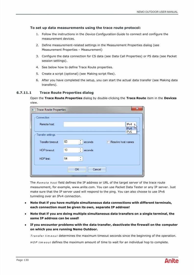
8/16/2019 Nemo Outdoor User Manual
http://slidepdf.com/reader/full/nemo-outdoor-user-manual 130/391
NEMO OUTDOOR USER MANUAL
Page 130
To set up data measurements using the trace route protocol:
1. Follow the instructions in the Device Configuration Guide to connect and configure themeasurement devices.
2. Define measurement-related settings in the Measurement Properties dialog (seeMeasurement Properties – Measurement)
3. Configure the data connection for CS data (see Data Call Properties) or PS data (see Packetsession settings) .
4. See below how to define Trace Route properties.
5. Create a script (optional) (see Making script files) .
6. After you have completed the setup, you can start the actual data transfer (see Making datatransfers) .
6.7.11.1 Trace Route Properties dialog
Open the Trace Route Properties dialog by double-clicking the Trace Route item in the Devices view.
The R e m o t e h o s t field defines the IP address or URL of the target server of the trace routemeasurement, for example, www.anite.com. You can use Packet Data Tester or any IP server. Just
make sure that the IP server used will respond to the ping. You can also choose to use IPv6tunneling over an IPv4 connection.
♦ Note that if you have multiple simultaneous data connections with different terminals,each connection must be given its own, separate IP address!
♦ Note that if you are doing multiple simultaneous data transfers on a single terminal, thesame IP address can be used!
♦ If you encounter problems with the data transfer, deactivate the firewall on the computeron which you are running Nemo Outdoor.
T r a n sf e r t i m e o u t determines the maximum timeout seconds since the beginning of the operation.
H O P t im e o u t defines the maximum amount of time to wait for an individual hop to complete.

8/16/2019 Nemo Outdoor User Manual
http://slidepdf.com/reader/full/nemo-outdoor-user-manual 131/391
NEMO OUTDOOR USER MANUAL
Page 131
H O P l im i t defines the maximum number of servers to be pinged along the way to the targetserver.
By selecting the R e so l v e h o s t n a m e s item, the names of the pinged servers will be reported byNemo Outdoor.
6.7.12 Making data transfers
After you have configured the data connection and selected and configured the data protocol, youcan start making the data transfers.
♦ Note! Firewall must be deactivated when making data transfers.
To make data transfers:
1. Activate the script by clicking the Start/Stop Scripts button.
♦ Note that after you have activated the script, you cannot control the measurement
manually until the script is finished or you interrupt the script by clicking the Stop Scriptsbutton.
2. To make manual CS data calls, click the Measurement control button in the Devices viewand select Start Data Call . Wait until the call is connected and connection established.
3. To make manual PS data calls, click the Measurement control button in the Devices viewand select Start Packet Session . Nemo Outdoor will automatically activate the PDPcontext and make the GPRS attach.
4. To end the data transfer/data call, select Stop Packet Session/ Stop Data Call .
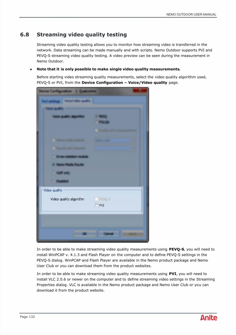
8/16/2019 Nemo Outdoor User Manual
http://slidepdf.com/reader/full/nemo-outdoor-user-manual 132/391
NEMO OUTDOOR USER MANUAL
Page 132
6.8 Streaming video quality testing
Streaming video quality testing allows you to monitor how streaming video is transferred in thenetwork. Data streaming can be made manually and with scripts. Nemo Outdoor supports PVI andPEVQ-S streaming video quality testing. A video preview can be seen during the measurement inNemo Outdoor.
♦ Note that it is only possible to make single video quality measurements.
Before starting video streaming quality measurements, select the video quality algorithm used,PEVQ-S or PVI, from the Device Configuration – Voice/Video quality page.
In order to be able to make streaming video quality measurements using PEVQ-S , you will need toinstall WinPCAP v. 4.1.3 and Flash Player on the computer and to define PEVQ-S settings in thePEVQ-S dialog. WinPCAP and Flash Player are available in the Nemo product package and NemoUser Club or you can download them from the product websites.
In order to be able to make streaming video quality measurements using PVI , you will need toinstall VLC 2.0.6 or newer on the computer and to define streaming video settings in the StreamingProperties dialog. VLC is available in the Nemo product package and Nemo User Club or you candownload it from the product website.

8/16/2019 Nemo Outdoor User Manual
http://slidepdf.com/reader/full/nemo-outdoor-user-manual 133/391
NEMO OUTDOOR USER MANUAL
Page 133
♦ PVI video quality parameters are not available with 64-bit operating systems. PVIstreaming without video quality parameters is supported with both 32- and 64-bitoperating systems.
Making streaming video quality measurements with PEVQ-S:
1. Check that WinPCAP v. 4.1.3 and Flash Player are installed on the computer.
2. Select the PEVQ-S option from the Device Configuration – Voice/video quality page.
3. Define the PEVQ-S settings in the PEVQ-S Properties dialog.
4. Start recording by clicking the Start Recording button . From the Measurement menu,select All Devices | Start/Stop Data Transfer to start the data transfer with all testdevices or <device name> | Start/Stop Data Transfer to start the data transfer with
just one device.
5. You can view, for example, from a line graph some streaming parameters. Open a line
graph ( Data | Line Graph | New ). Press the Add New Layer button and select VideoQuality MOS in the Y field and click OK . The graph will now display the selectedparameter.
6. From the Measurement menu, select Start/Stop Data Transfer to end the data transferor wait until the entire video clip has been streamed.
Making streaming video quality measurements with PVI:
1. Check that VLC is installed on the computer.
2. Define the video streaming settings in the Streaming Properties dialog.
3.
Start recording by clicking the Start Recording button . From the Measurement menu,select All Devices | Start/Stop Data Transfer to start the data transfer with all testdevices or <device name> | Start/Stop Data Transfer to start the data transfer with
just one device.
4. You can view, for example, from a line graph some streaming parameters. Open a linegraph ( Data | Line Graph | New ). Press the Add New Layer button and select VideoQuality MOS in the Y field and click OK . The graph will now display the selectedparameter.
5. From the Measurement menu, select Start/Stop Data Transfer to end the data transferor wait until the entire video clip has been streamed.

8/16/2019 Nemo Outdoor User Manual
http://slidepdf.com/reader/full/nemo-outdoor-user-manual 134/391
NEMO OUTDOOR USER MANUAL
Page 134
6.8.1 PEVQ-S Properties dialog
When making video streaming quality measurements with the PEVQ-S algorithm, you need todefine some settings in the PEVQ-S Properties dialog.
Vi d e o offers a selection of preloaded videos that can be used in the testing. Only these preloadedvideos can be used for testing. The videos must be stored in folder Nemo Tools\Video Files. Toupdate the video files from the Opticom server, click the Update button.
T r a n sf e r t i m e o u t defines the time in seconds for how long Nemo Outdoor waits during a transfer ifthere is a break in the data flow. If the transfer does not continue within the defined time, thetransfer will fail.
Select or clear the D i s p la y v i d e o s t r e a m option to display/hide the video stream window duringthe data transfer.
The dialog also displays some information about the network adapters recognized by NemoOutdoor. If there are problems with PEVQ-S testing, check that your device appears on the list. Ifnot, restart the laptop and the adapter should appear on the list.
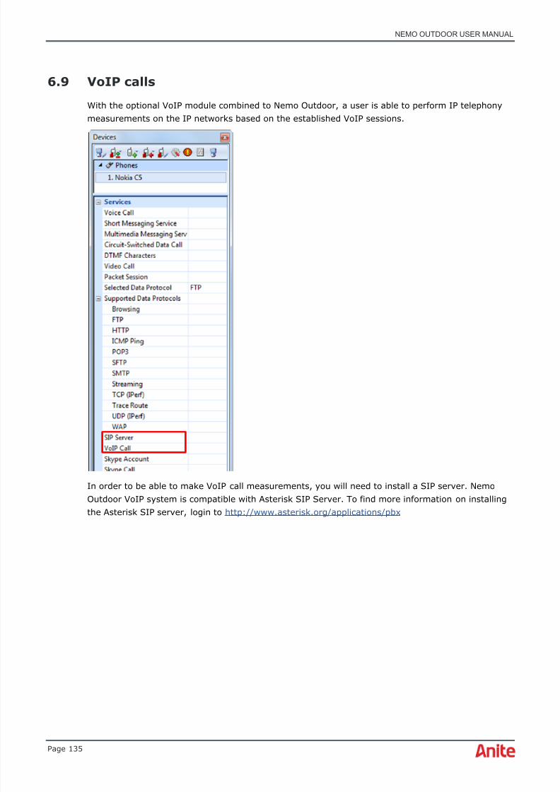
8/16/2019 Nemo Outdoor User Manual
http://slidepdf.com/reader/full/nemo-outdoor-user-manual 135/391
NEMO OUTDOOR USER MANUAL
Page 135
6.9 VoIP calls
With the optional VoIP module combined to Nemo Outdoor, a user is able to perform IP telephonymeasurements on the IP networks based on the established VoIP sessions.
In order to be able to make VoIP call measurements, you will need to install a SIP server. NemoOutdoor VoIP system is compatible with Asterisk SIP Server. To find more information on installingthe Asterisk SIP server, login to http://www.asterisk.org/applications/pbx

8/16/2019 Nemo Outdoor User Manual
http://slidepdf.com/reader/full/nemo-outdoor-user-manual 136/391
NEMO OUTDOOR USER MANUAL
Page 136
To start making VoIP call measurements, you will need to define some VoIP session settings in theSIP Server Settings and VoIP Call Configuration dialogs. Open the SIP Server Settings dialog bydouble-clicking the SIP Server item in the Devices view.
D o m a in defines the address of the SIP server, e.g. pbx.nemo.fi.
P o r t defines the SIP port. The default SIP port is 5060.
U se r n a m e / P as sw o r d defines the username that the user has registered to the server and thecorresponding password.
Co n n e c t i o n t i m e o u t defines the timeout while trying to connect to the server.
R e g i st r a t i o n d u r a t i o n defines the duration for which the SIP registration is valid.
A u t o m a t i c r e g i s t r a t i o n , when selected, automatically registers the user to the SIP server (as
soon as Packet Session has been created).When selected, Use SIP proxy option enables the user to send outbound SIP messager via Proxy.
P r o x y a d d r e s s/ p o r t defines the proxy, through which SIP messages are sent.
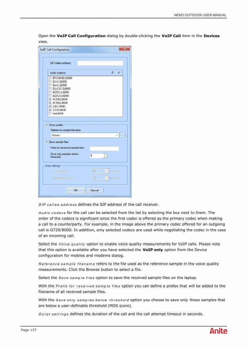
8/16/2019 Nemo Outdoor User Manual
http://slidepdf.com/reader/full/nemo-outdoor-user-manual 137/391
NEMO OUTDOOR USER MANUAL
Page 137
Open the VoIP Call Configuration dialog by double-clicking the VoIP Call item in the Devices view.
S I P c a l l e e a d d r e s s defines the SIP address of the call receiver.
A u d i o c o d e c s for the call can be selected from the list by selecting the box next to them. Theorder of the codecs is significant since the first codec is offered as the primary codec when makinga call to a counterparty. For example, in the image above the primary codec offered for an outgoingcall is G729/8000. In addition, only selected codecs are used while negotiating the codec in the caseof an incoming call.
Select the Vo i c e q u a l i t y option to enable voice quality measurements for VoIP calls. Please notethat this option is available after you have selected the VoIP only option from the Deviceconfiguration for mobiles and modems dialog.
R e f e r e n c e s a m p l e f il e n a m e refers to the file used as the reference sample in the voice qualitymeasurements. Click the Browse button to select a file.
Select the S a v e s a m p l e f i le s option to save the received sample files on the laptop.
With the P r e f ix f o r r e c e i v e d s a m p l e f i le s option you can define a prefex that will be added to thefilename of all received sample files.
With the S a v e o n l y s a m p l e s b e l o w t h r e s h o l d option you choose to save only those samples that
are below a user-definable threshold (MOS score).
S cr i p t s e t t i n g s defines the duration of the call and the call attempt timeout in seconds.

8/16/2019 Nemo Outdoor User Manual
http://slidepdf.com/reader/full/nemo-outdoor-user-manual 138/391
NEMO OUTDOOR USER MANUAL
Page 138
Making VoIP measurements:
1. Define SIP Server Settings and VoIP Call Configurations.
2. To start packet session, click on the Measurement control button | Start PacketSession .
3. To register SIP server, click on the Measurement control button | Register SIP Server .
4. To start VoIP measurement, click on the Measurement control button | Start VoIP Call .
5. To end VoIP measurement, click on the Measurement control button | Stop VoIP Call .
6. Finally, to unregister SIP server, click on the Measurement control button | Unregister SIPServer (Note: This is not a mandatory step, a new call can be made without unregistering)
6.10 Application testing
Nemo Outdoor offers several application testing features.
6.10.1 Facebook testing
In order to be able to test the Facebook application, you will need to set up a Facebook account.
To start running Facebook tests, you will need to define some Facebook settings in the FacebookConfiguration dialog. Open the dialog by double-clicking the Facebook item in the Devices view.
♦ Please note that if the Facebook item is not visible in the Devices view, your NemoOutdoor license does not support Facebook testing.
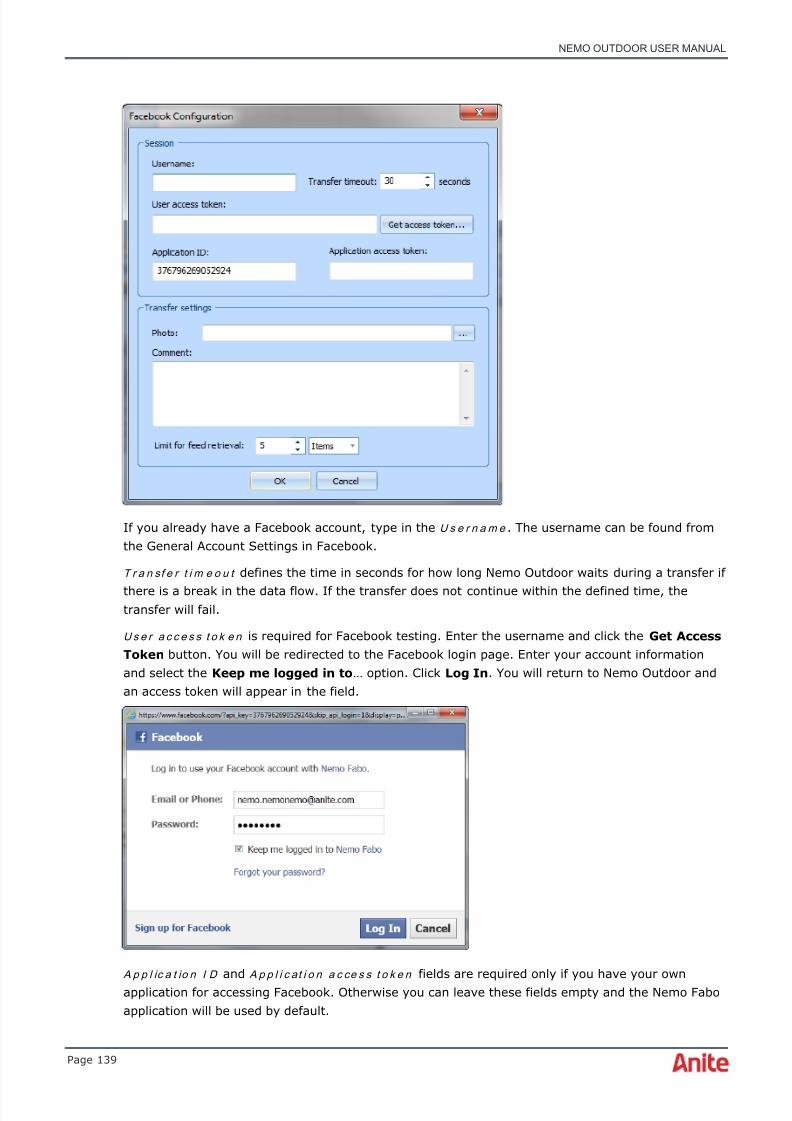
8/16/2019 Nemo Outdoor User Manual
http://slidepdf.com/reader/full/nemo-outdoor-user-manual 139/391
NEMO OUTDOOR USER MANUAL
Page 139
If you already have a Facebook account, type in the U s e r n a m e . The username can be found fromthe General Account Settings in Facebook.
T r a n sf e r t i m e o u t defines the time in seconds for how long Nemo Outdoor waits during a transfer if
there is a break in the data flow. If the transfer does not continue within the defined time, thetransfer will fail.
U s e r a c c e s s t o k e n is required for Facebook testing. Enter the username and click the Get AccessToken button. You will be redirected to the Facebook login page. Enter your account informationand select the Keep me logged in to … option. Click Log In . You will return to Nemo Outdoor andan access token will appear in the field.
A p p l ic a t io n I D and A p p l i c at i o n a c ce s s t o k e n fields are required only if you have your ownapplication for accessing Facebook. Otherwise you can leave these fields empty and the Nemo Faboapplication will be used by default.

8/16/2019 Nemo Outdoor User Manual
http://slidepdf.com/reader/full/nemo-outdoor-user-manual 140/391
NEMO OUTDOOR USER MANUAL
Page 140
♦ When performing Facebook testing with multiple devices, use the same Facebook accounton all of them. With Nemo Invex II, use different UICs for the data connections and thenyou can use individual Facebook accounts for each of them.
You can define a P h o t o that will be uploaded on the wall of your Facebook profile.
C o m m e n t is text that will either be posted as a status update (without a photo) or as a caption fora photo.
L i m i t f o r f e e d r e t r i e v a l defines how many items or from how many days items will be retrievedfrom the wall when the user executes the Get Wall Feed command.
After defining Facebook settings, return to the Devices view and start a packet session. Click theMeasurement control button and select one of the Facebook-related commands. The followinginformation is logged for each command: operation type, success/failure, time elapsed, and amountof data received/sent.
G e t f r i e n d l i st will download the friend list from you Facebook account.
G e t w a l l f e e d will download the wall feed from you Facebook account. The amount of datadownloaded is defined by the Limit for feed retrieval setting in the Facebook Configuration dialog.
♦ Please note that Facebook has its own limits for the number of account actions per day.Check the Facebook Help Center for current information about the limits.
P o s t s t a t u s u p d a t e will upload the text typed in the Comment field and post it on the wall of yourFacebook profile.
P o st p h o t o will upload the photo selected in the Facebook Configuration dialog and the text typedin the Comment field as caption on the wall of your Facebook profile.
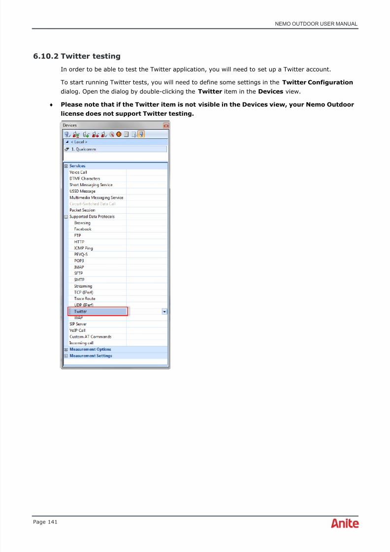
8/16/2019 Nemo Outdoor User Manual
http://slidepdf.com/reader/full/nemo-outdoor-user-manual 141/391
NEMO OUTDOOR USER MANUAL
Page 141
6.10.2 Twitter testing
In order to be able to test the Twitter application, you will need to set up a Twitter account.
To start running Twitter tests, you will need to define some settings in the Twitter Configuration dialog. Open the dialog by double-clicking the Twitter item in the Devices view.
♦ Please note that if the Twitter item is not visible in the Devices view, your Nemo Outdoorlicense does not support Twitter testing.

8/16/2019 Nemo Outdoor User Manual
http://slidepdf.com/reader/full/nemo-outdoor-user-manual 142/391
NEMO OUTDOOR USER MANUAL
Page 142
If you want to follow the Twitter feed of a specific user or a hashtag, type in the username/hashtagin the @ U s e r / # Fe e d field without the @ or # symbols.
T r a n sf e r t i m e o u t defines the time in seconds for how long Nemo Outdoor waits during a transfer ifthere is a break in the data flow. If the transfer does not continue within the defined time, thetransfer will fail.

8/16/2019 Nemo Outdoor User Manual
http://slidepdf.com/reader/full/nemo-outdoor-user-manual 143/391
NEMO OUTDOOR USER MANUAL
Page 143
U s e r a c c e s s t o k e n and U s e r a c c e s s t o k e n s e c r e t are required for Twitter testing. Click the GetAccess Token button. You will be redirected to the Twitter login page.
Enter your account information and select the Remember me option. Click Sign In . You will returnto Nemo Outdoor and the access token and access token secret will appear in the field.
A p p l i ca t i o n a c ce s s t o k e n and A p p l i c at i o n a c ce s s t o k e n s e cr e t fields are required only if youhave your own application for accessing Twitter. Otherwise you can leave these fields empty.
You can define an I m a g e that will be uploaded to your Twitter feed.
C o m m e n t is text that will be posted as a tweet.
L i m i t f o r f e e d r e t r i e v a l defines how many items or from how many days items will be retrieved
from the feed when the user executes the Get Feed command.♦ Please note that Twitter has its own limits for the number of account actions per day.
Check the Twitter Help Center for current information about the limits.

8/16/2019 Nemo Outdoor User Manual
http://slidepdf.com/reader/full/nemo-outdoor-user-manual 144/391
NEMO OUTDOOR USER MANUAL
Page 144
After defining Twitter settings, return to the Devices view and start a packet session. Click theMeasurement control button and select Start New Data Transfer | Twitter and then one of theTwitter-related commands.
G e t U s e r F e e d will download your own Twitter feed.
L o a d P r o f i l e will download the Twitter feed from the selected user (defined in the TwitterConfiguration dialog , @User / #Feed field).
F o l lo w F e e d will download the feed from the selected Twitter hashtag. The amount of datadownloaded is defined by the Limit for feed retrieval setting in the Twitter Configuration dialog.
P o s t F e e d will upload the text typed in the Twitter Configuration dialog, Comment field andpost it on your Twitter feed.
P o s t I m a g e will upload the image selected in the Twitter Configuration dialog on your Twitterfeed.
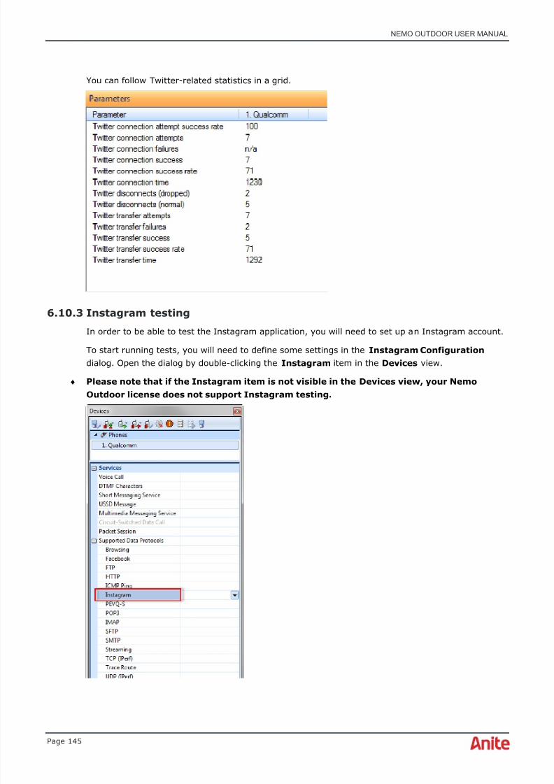
8/16/2019 Nemo Outdoor User Manual
http://slidepdf.com/reader/full/nemo-outdoor-user-manual 145/391
NEMO OUTDOOR USER MANUAL
Page 145
You can follow Twitter-related statistics in a grid.
6.10.3 Instagram testing
In order to be able to test the Instagram application, you will need to set up an Instagram account.
To start running tests, you will need to define some settings in the Instagram Configuration dialog. Open the dialog by double-clicking the Instagram item in the Devices view.
♦ Please note that if the Instagram item is not visible in the Devices view, your NemoOutdoor license does not support Instagram testing.

8/16/2019 Nemo Outdoor User Manual
http://slidepdf.com/reader/full/nemo-outdoor-user-manual 146/391
NEMO OUTDOOR USER MANUAL
Page 146
If you already have an Instagram account, type in the U s e r n a m e .
T r a n sf e r t i m e o u t defines the time in seconds for how long Nemo Outdoor waits during a transfer ifthere is a break in the data flow. If the transfer does not continue within the defined time, thetransfer will fail.
U s e r a c c e s s t o k e n is required for Instagram testing. Click the Get Access Token button. You willbe redirected to the Instagram login page. Enter your account information and click Log In . Youwill return to Nemo Outdoor and an access token will appear in the field.
A p p l ic a t io n I D and A p p l i c at i o n s e cr e t fields are required only if you have your own applicationfor accessing Instagram. Otherwise you can leave these fields empty.
Se a r ch a b l e t a g / u s e r n a m e defines a tag or a username from which the feed will be downloaded.
L im i t f o r f e ed r e t r i e v a l defines how many items or from how many days items will be retrievedfrom the feed when the user executes the Get Feed command.

8/16/2019 Nemo Outdoor User Manual
http://slidepdf.com/reader/full/nemo-outdoor-user-manual 147/391
NEMO OUTDOOR USER MANUAL
Page 147
After defining the settings, return to the Devices view and start a packet session. Click theMeasurement control button and select Start New Data Transfer | Instagram and then one ofthe Instagram-related commands.
G e t U s e r F e e d will download the Instagram feed of a selected user.
G e t S e l f F e e d will download your own Instagram feed.
G e t P o p u l a r F e e d will download the popular feed from Instagram.
S e ar c h M e d i a w i t h a Ta g will download the feed from the selected hashtag (defined in theInstagram Configuration dialog). The amount of data downloaded is defined by the Limit for feedretrieval setting in the Instagram Configuration dialog.
You can follow Instagram-related statistics in a grid.

8/16/2019 Nemo Outdoor User Manual
http://slidepdf.com/reader/full/nemo-outdoor-user-manual 148/391
NEMO OUTDOOR USER MANUAL
Page 148
6.10.4 Dropbox testing
In order to be able to test the Dropbox application, you will need to set up a Dropbox account.
To start running tests, you will need to define some settings in the Dropbox Configuration dialog.Open the dialog by double-clicking the Dropbox item in the Devices view.
♦ Please note that if the Dropbox item is not visible in the Devices view, your NemoOutdoor license does not support Dropbox testing.
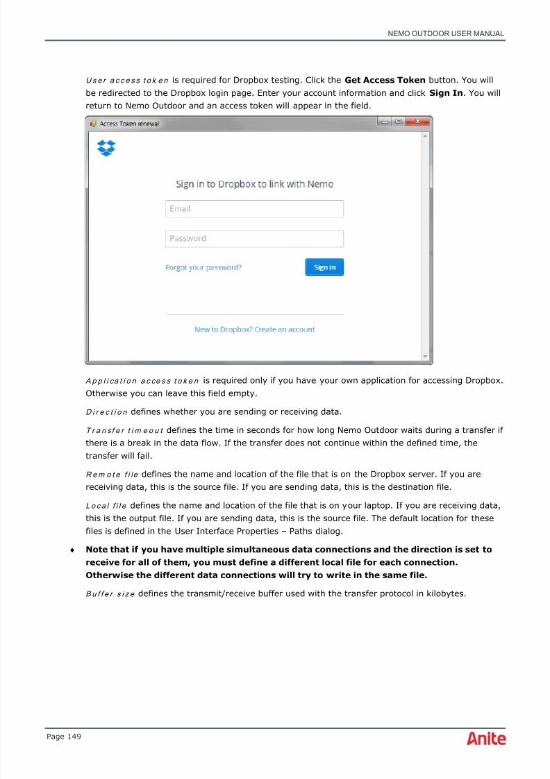
8/16/2019 Nemo Outdoor User Manual
http://slidepdf.com/reader/full/nemo-outdoor-user-manual 149/391
NEMO OUTDOOR USER MANUAL
Page 149
U s e r a c c e s s t o k e n is required for Dropbox testing. Click the Get Access Token button. You willbe redirected to the Dropbox login page. Enter your account information and click Sign In . You willreturn to Nemo Outdoor and an access token will appear in the field.
A p p l i ca t i o n a c ce s s t o k e n is required only if you have your own application for accessing Dropbox.Otherwise you can leave this field empty.
D i r e c t i o n defines whether you are sending or receiving data.
T r a n sf e r t i m e o u t defines the time in seconds for how long Nemo Outdoor waits during a transfer ifthere is a break in the data flow. If the transfer does not continue within the defined time, thetransfer will fail.
R e m o t e f i le defines the name and location of the file that is on the Dropbox server. If you arereceiving data, this is the source file. If you are sending data, this is the destination file.
L o c a l f i l e defines the name and location of the file that is on your laptop. If you are receiving data,this is the output file. If you are sending data, this is the source file. The default location for thesefiles is defined in the User Interface Properties – Paths dialog.
♦ Note that if you have multiple simultaneous data connections and the direction is set toreceive for all of them, you must define a different local file for each connection.Otherwise the different data connections will try to write in the same file.
B u f f e r s i z e defines the transmit/receive buffer used with the transfer protocol in kilobytes.
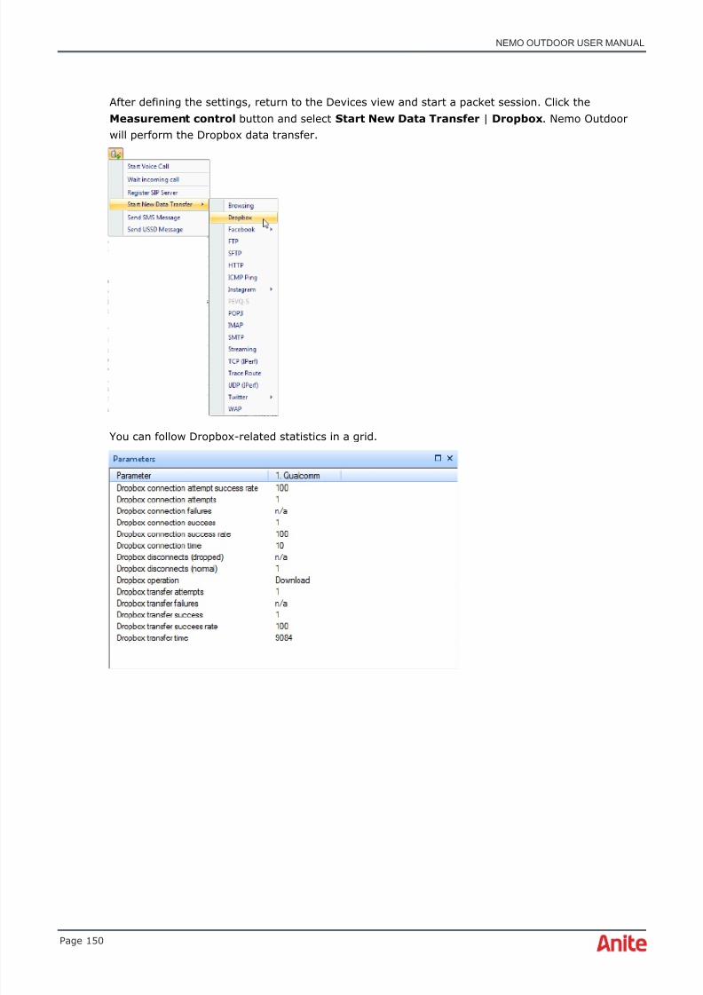
8/16/2019 Nemo Outdoor User Manual
http://slidepdf.com/reader/full/nemo-outdoor-user-manual 150/391
NEMO OUTDOOR USER MANUAL
Page 150
After defining the settings, return to the Devices view and start a packet session. Click theMeasurement control button and select Start New Data Transfer | Dropbox . Nemo Outdoorwill perform the Dropbox data transfer.
You can follow Dropbox-related statistics in a grid.

8/16/2019 Nemo Outdoor User Manual
http://slidepdf.com/reader/full/nemo-outdoor-user-manual 151/391
NEMO OUTDOOR USER MANUAL
Page 151
6.11 SMS testing
SMS testing allows you to monitor how text messages are transferred in the network. Open theSMS Testing dialog by double-clicking the Short Messaging Service item in the Devices view.
♦ Note that the Qualcomm IMS IR.92 VoLTE option is required for SMS over LTE testing. Inaddition, if you are using the Samsung IMS, you will need the Samsung IMS IR.92 VoLTEoption.
P h o n e N u m b e r defines the number of the mobile where you are sending the test messages. Enterthe number without spaces and with the international country code; for example, +3581234567.
S e r v i ce C e n t e r A d d r e s s defines the message center number of the mobile from where themessages are sent. The number is found from the test mobile SMS settings.
T im e o u t defines the time in seconds after which the SMS sending attempt is terminated.
When the En d - t o - e n d m e ss a g e option is selected, a unique ID consisting of 42 characters isadded to the beginning of the message text when the SMS is sent. When the measurement file isadded to the Nemo Analyze database, Nemo Analyze is able to recognize the SMS and the time ittook for it to reach its destination from the time of sending during post-processing.
All handlers support sending and receiving concatenated SMS messages.

8/16/2019 Nemo Outdoor User Manual
http://slidepdf.com/reader/full/nemo-outdoor-user-manual 152/391
NEMO OUTDOOR USER MANUAL
Page 152
M e s s a g e refers to the user-defined test message that will be sent. The limit is set to 15000characters.
Making SMS testing measurements:
♦ Note that with CDMA terminals, before carrying out SMS testing in Nemo Outdoor, youmust send an SMS to the target phone number using the terminal's keypad. After thatNemo Outdoor can be used to send the same message again.
1. Define the Phone Number (with the international country code and without spaces) whereyou are sending the test SMS message.
2. Enter the Service Center Address of the test mobile from which you are sending the testSMS. The number can be found from your mobile SMS Settings.
3. Define the Timeout , i.e., the time in seconds after which the SMS sending attempt isterminated.
4. Type in the test message and click OK .5. Start recording by clicking the Start Recording button . From the Measurement menu,
select All Devices | Send SMS Message to send an SMS with all test devices or <devicename> | Send SMS Message to send an SMS with just one device. Nemo Outdoor willsend the test SMS.
6. You can view, for example, from a grid window if the test message was deliveredsuccessfully. Open an event grid ( Data | Events Grid | New ). Open the Grid Properties dialog (right-click on the grid and select Properties from the popup menu). Clear allselections and select the Short Message Service item and click OK . The grid will nowdisplay only the selected SMS testing-related events.
6.11.1 SMS testing with CDMA terminals
SMS testing with CDMA does not require you to do any configurations prior to SMS testing for theterminal. The verified CDMA terminals supporting SMS testing are
• Huawei C7600
• LG C680
• LG C676
• LG KX206
• LG KX256
• LG VX8100
• LG VX8350
• LG VX8360
• Samsung SCH A870
The testing goes as follows:
1. Connect and add the terminal to Nemo Outdoor.
2. Prior to starting SMS testing in Nemo Outdoor, send an SMS to the target phone numberfrom the phone’s keypad.

8/16/2019 Nemo Outdoor User Manual
http://slidepdf.com/reader/full/nemo-outdoor-user-manual 153/391
NEMO OUTDOOR USER MANUAL
Page 153
3. In the Devices view, click on the Measurement control button and select Send SMSMessage . Nemo Outdoor sends the same message as was sent by the user from the actualphone interface by retrieving the text message from the phone’s Saved messages folder.
6.12 MMS testingMMS testing allows you to monitor how multimedia messages are transferred in the network. MMSmessages can be sent manually and with scripts. In addition to successfully sent/received MMSmessages, also sending/receiving attempts and sending/receiving failures are recorded enablingstatistical success rate calculations. Nemo Outdoor measures total MMS sending delay. Alsoseparate delays from Attach, PDP context activation, logging to MMSC, and messagesending/receiving are recorded.
In order to be able to make MMS measurements, you will need to define some MMS-related settingsin the Packet Session Settings dialog.
♦ Note that you need to define the MMS settings also on the device receiving the MMSmessages.
♦ If you are using Nokia N95, 6120, and 6121 mobiles for MMS testing, please see chapterMMS settings for Nokia N95, 6120, and 6121. Some special MMS settings are required.
♦ Please note that if you create a script for making MMS measurements, the script must notcontain a PDP activation command.
6.12.1 Packet session settings for MMS
Open the Packet Session Settings - MMS dialog by double-clicking the Multimedia MessagingService item in the Devices view. The MMS tab is opened by default.
Packet Session settings are needed to establish the packet switched data connection. All theparameters in the Packet Session and the Basic QoS and Extended QoS tabs are operator-specific.You must select the correct parameters to make the packet transfer function. Contact the operatorof the network that you are measuring.
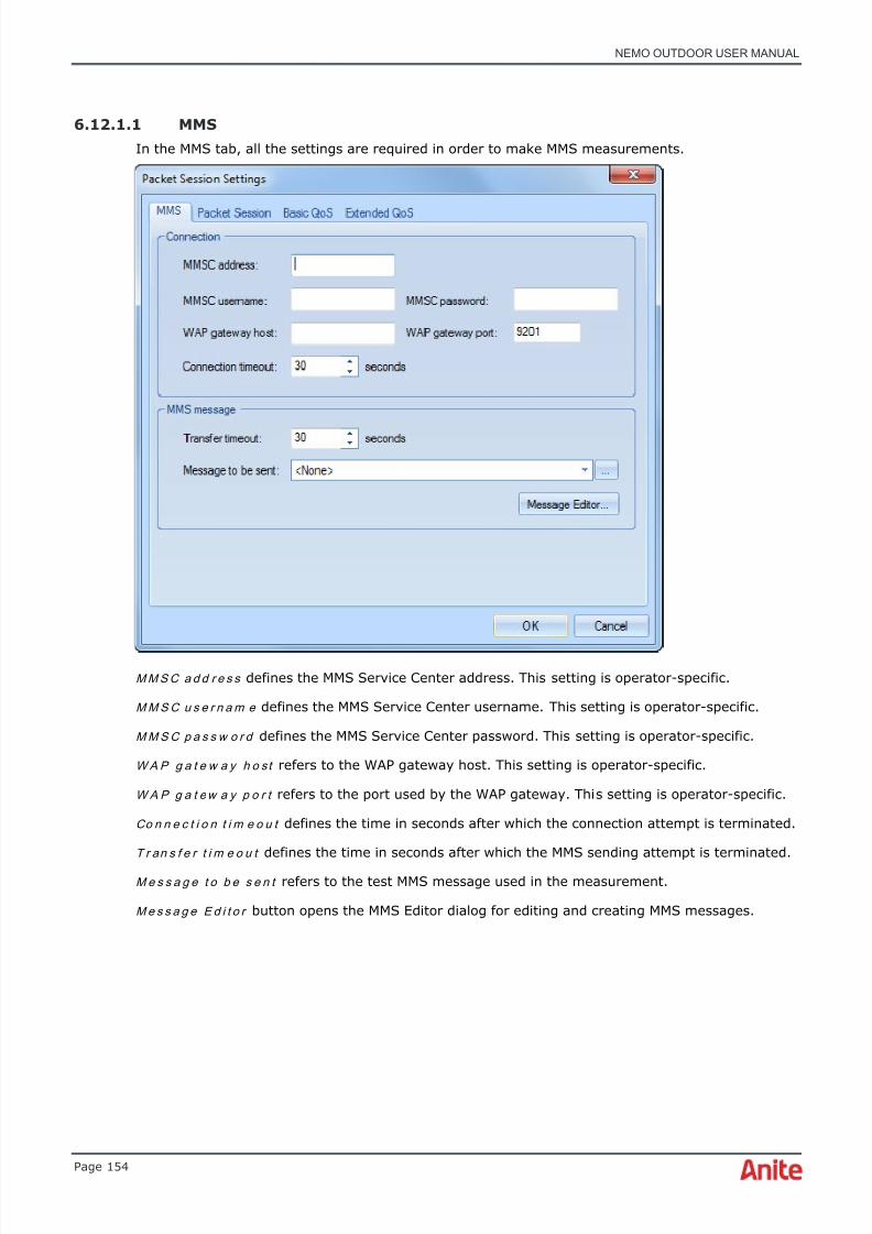
8/16/2019 Nemo Outdoor User Manual
http://slidepdf.com/reader/full/nemo-outdoor-user-manual 154/391
NEMO OUTDOOR USER MANUAL
Page 154
6.12.1.1 MMS
In the MMS tab, all the settings are required in order to make MMS measurements.
M M S C a d d r e s s defines the MMS Service Center address. This setting is operator-specific.
M M S C u s e r n a m e defines the MMS Service Center username. This setting is operator-specific.
M M S C p a s s w o r d defines the MMS Service Center password. This setting is operator-specific.
WA P g a t e w a y h o s t refers to the WAP gateway host. This setting is operator-specific.
WA P g a t e w a y p o r t refers to the port used by the WAP gateway. This setting is operator-specific.
Co n n e c t i o n t i m e o u t defines the time in seconds after which the connection attempt is terminated.
T r an s f e r t i m e o u t defines the time in seconds after which the MMS sending attempt is terminated.
M e s s a g e t o b e s e n t refers to the test MMS message used in the measurement.
M e s s a g e E d i t o r button opens the MMS Editor dialog for editing and creating MMS messages.
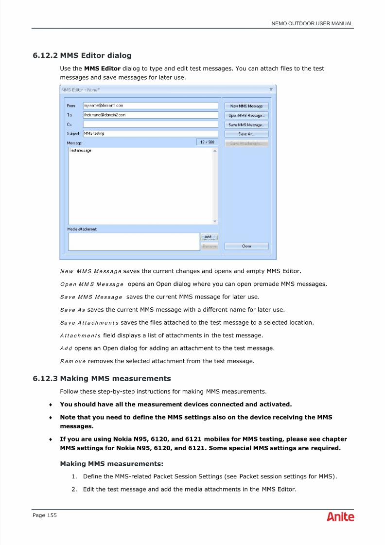
8/16/2019 Nemo Outdoor User Manual
http://slidepdf.com/reader/full/nemo-outdoor-user-manual 155/391
NEMO OUTDOOR USER MANUAL
Page 155
6.12.2 MMS Editor dialog
Use the MMS Editor dialog to type and edit test messages. You can attach files to the testmessages and save messages for later use.
N e w M M S M e ss a g e saves the current changes and opens and empty MMS Editor.
O p e n M M S M e s sa g e opens an Open dialog where you can open premade MMS messages.S a v e M M S M e s s a g e saves the current MMS message for later use.
S a v e A s saves the current MMS message with a different name for later use.
Sa v e A t t a c h m e n t s saves the files attached to the test message to a selected location.
A t t a c h m e n t s field displays a list of attachments in the test message.
A d d opens an Open dialog for adding an attachment to the test message.
R em o v e removes the selected attachment from the test message.
6.12.3 Making MMS measurementsFollow these step-by-step instructions for making MMS measurements.
♦ You should have all the measurement devices connected and activated.
♦ Note that you need to define the MMS settings also on the device receiving the MMSmessages.
♦ If you are using Nokia N95, 6120, and 6121 mobiles for MMS testing, please see chapterMMS settings for Nokia N95, 6120, and 6121. Some special MMS settings are required.
Making MMS measurements:
1. Define the MMS-related Packet Session Settings (see Packet session settings for MMS) .2. Edit the test message and add the media attachments in the MMS Editor.
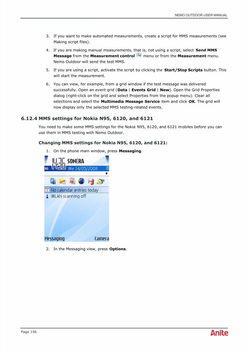
8/16/2019 Nemo Outdoor User Manual
http://slidepdf.com/reader/full/nemo-outdoor-user-manual 156/391
NEMO OUTDOOR USER MANUAL
Page 156
3. If you want to make automated measurements, create a script for MMS measurements (seeMaking script files) .
4. If you are making manual measurements, that is, not using a script, select Send MMSMessage from the Measurement control menu or from the Measurement menu.
Nemo Outdoor will send the test MMS.
5. If you are using a script, activate the script by clicking the Start/Stop Scripts button. Thiswill start the measurement.
6. You can view, for example, from a grid window if the test message was deliveredsuccessfully. Open an event grid ( Data | Events Grid | New ). Open the Grid Propertiesdialog (right-click on the grid and select Properties from the popup menu). Clear allselections and select the Multimedia Message Service item and click OK . The grid willnow display only the selected MMS testing-related events.
6.12.4 MMS settings for Nokia N95, 6120, and 6121
You need to make some MMS settings for the Nokia N95, 6120, and 6121 mobiles before you canuse them in MMS testing with Nemo Outdoor.
Changing MMS settings for Nokia N95, 6120, and 6121:
1. On the phone main window, press Messaging .
2. In the Messaging view, press Options .

8/16/2019 Nemo Outdoor User Manual
http://slidepdf.com/reader/full/nemo-outdoor-user-manual 157/391
NEMO OUTDOOR USER MANUAL
Page 157
3.
From the menu, select Settings .
4. From the Settings view, select Multimedia message .
5. Select the Access point in use option and change it to None .
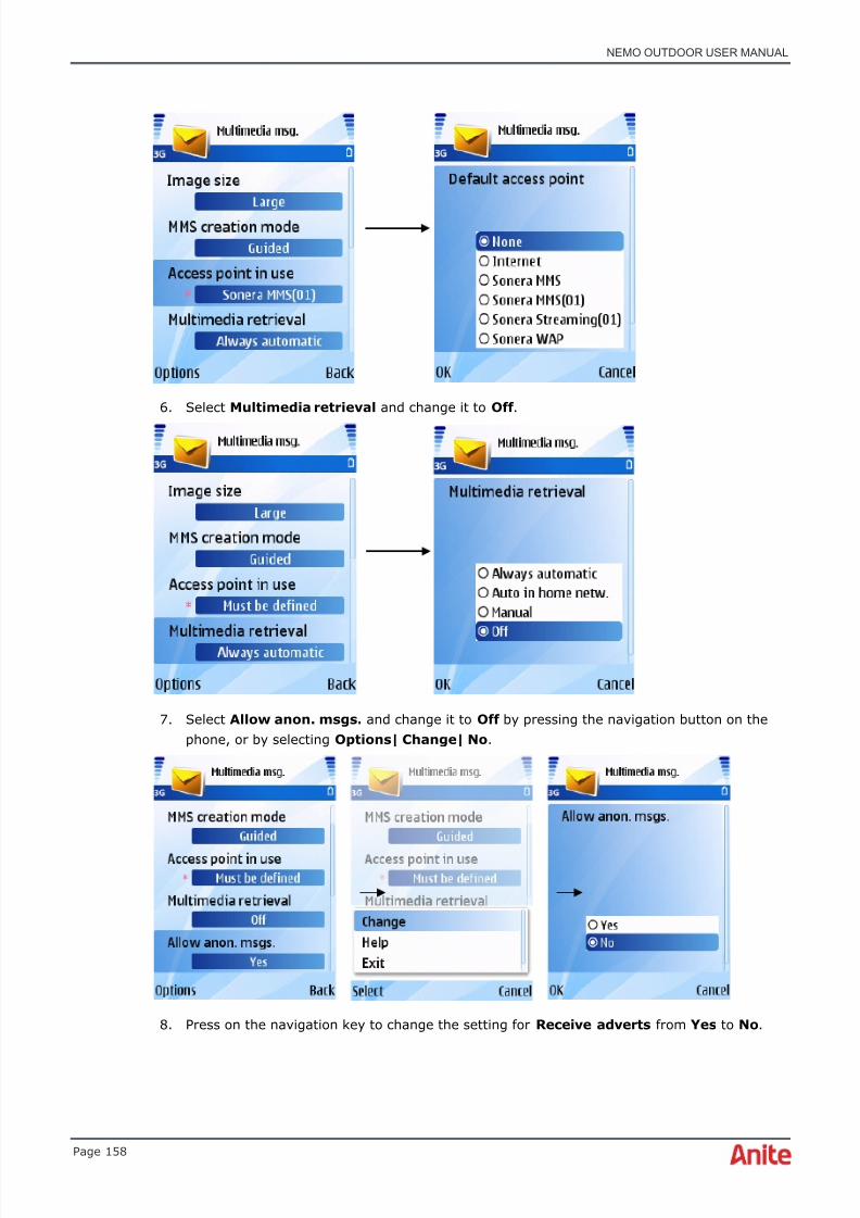
8/16/2019 Nemo Outdoor User Manual
http://slidepdf.com/reader/full/nemo-outdoor-user-manual 158/391
NEMO OUTDOOR USER MANUAL
Page 158
6. Select Multimedia retrieval and change it to Off .
7. Select Allow anon. msgs. and change it to Off by pressing the navigation button on thephone, or by selecting Options| Change| No .
8. Press on the navigation key to change the setting for Receive adverts from Yes to No .

8/16/2019 Nemo Outdoor User Manual
http://slidepdf.com/reader/full/nemo-outdoor-user-manual 159/391
NEMO OUTDOOR USER MANUAL
Page 159
9. Press the navigation button on the phone to change the Receive report setting from Yes to No .
10. Press Back and select Yes to confirm the changes. Finally switch the mobile off and on.
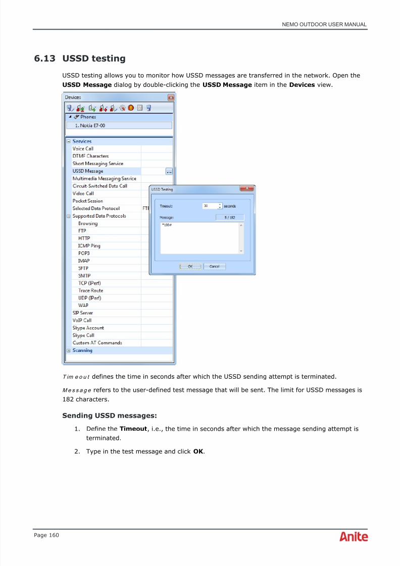
8/16/2019 Nemo Outdoor User Manual
http://slidepdf.com/reader/full/nemo-outdoor-user-manual 160/391
NEMO OUTDOOR USER MANUAL
Page 160
6.13 USSD testing
USSD testing allows you to monitor how USSD messages are transferred in the network. Open theUSSD Message dialog by double-clicking the USSD Message item in the Devices view.
T im e o u t defines the time in seconds after which the USSD sending attempt is terminated.
M e s s a g e refers to the user-defined test message that will be sent. The limit for USSD messages is182 characters.
Sending USSD messages:
1. Define the Timeout , i.e., the time in seconds after which the message sending attempt isterminated.
2. Type in the test message and click OK .

8/16/2019 Nemo Outdoor User Manual
http://slidepdf.com/reader/full/nemo-outdoor-user-manual 161/391
NEMO OUTDOOR USER MANUAL
Page 161
3. Start recording by clicking the Start Recording button . In the Devices view, click theMeasurement Control button and select Send USSD Message to send a USSD messagewith just one device. Nemo Outdoor will send the message.
4. You can view, for example, from a grid window if the test message was deliveredsuccessfully. Open an event grid ( Data | Events Grid | New ). Open the Grid Properties dialog (right-click on the grid and select Properties from the popup menu). Clear allselections and select the USSD item and click OK . The grid will now display only theselected USSD message testing-related events.
6.14 Start external application
This feature allows users to launch external applications from Nemo Outdoor as a part of theautomatic measurement sequence. You can define the executable as well as the command-lineparameters. With Nemo Invex, you can run external applications also on the measurement servers
(UICs).The external application can be used to launch any proprietary or third-party applications that arenot built into Nemo Outdoor. This enables, for example, the testing of data protocols that are notcurrently supported by Nemo Outdoor. You can then monitor the data throughputs from the PPPdata throughput parameter.
The external application feature can also be used to test web browsing. An APP event is written tothe log file when a web browser is launched and closed. The user must set the cache size tominimum from the browser settings.
The Start External Application dialog is accessed through the Script Editor , Add menu. SelectStart External Application from the menu.

8/16/2019 Nemo Outdoor User Manual
http://slidepdf.com/reader/full/nemo-outdoor-user-manual 162/391
8/16/2019 Nemo Outdoor User Manual
http://slidepdf.com/reader/full/nemo-outdoor-user-manual 163/391
NEMO OUTDOOR USER MANUAL
Page 163
H o s t n a m e refers to the IP address or URL that is being pinged, for example, www.anite.com. Youcan use Packet Data Tester or any IP server. Just make sure that the IP server used will respond tothe ping.
P a c k e t s i z e is the size of the ping packet that is used to measure ping time. The value determinesthe size of the packet sent to the server. In addition, it determines the size of the reply packet thatthe server uses to reply Nemo Outdoor.
T im e o u t determines the maximum time that Nemo Outdoor waits for a reply packet from the
server. If this time is exceeded, the ping measurement event will be created by using the timeoutparameter(=-1).
D e l a y defines the delay duration in milliseconds. In addition to the duration, also define where thedelay will occur. The options are:
• D e l ay b e t w e e n r e q u e s t s which means the protocol will always wait for a reply beforesending new request. If the delay is less than the ping delay, a new request is sentimmediately after the reply.
• D e l ay f r o m r e p l y t o r e q u e s t which means a new ping is sent after a reply is received.
Select the R e p e a t n t i m e s option if you would like to define the number of times the pingmeasurement is repeated.
Select the R e p e a t u n t i l s t o p p e d option if you would like to continue the ping measurement untilyou stop it manually.
Example 1. RTT time is 100ms and “delay from reply to request” is set to 1 s. New request is sentevery 1.1s (100ms + 1000ms). If “delay between request” is selected, a new request is sent every1000ms.

8/16/2019 Nemo Outdoor User Manual
http://slidepdf.com/reader/full/nemo-outdoor-user-manual 164/391
NEMO OUTDOOR USER MANUAL
Page 164
Example 2. RTT time is 100ms and “delay from reply to request” is set to 50ms. New request issent every 150ms (100ms + 50ms). If “delay between request” is selected, a new request is sentevery 100ms because the protocol always waits for a reply before sending a new request.
To make ping measurements:
1. Open the Ping Settings dialog by double-clicking the ICMP Ping item in the Devices view.
2. Define the required ping parameters and click OK .
3. Click the Start Recording button .
4. In the Devices view, click on the Measurement control button and select Start
Packet Session . Wait until the status field in the Device Status window says ‘PDP Context Activated’ .
5. From the Measurement control menu, select Start ICMP Ping . If you selected the Pinguntil stopped option in the Ping Settings dialog, select Stop ICMP Ping to stop the pingmeasurement. Otherwise, the ping will be repeated the user-defined number of times.
6.16 Indoor mode
Nemo Outdoor indoor mode should be used when making measurements indoors. The mode isactivated by clicking the button in the toolbar or by selecting Indoor Mode from theMeasurement menu.
When the indoor mode is activated the functionality of Nemo Outdoor changes:
• To start measuring an Indoor window needs to be open and a floorplan loaded.
• When the measurement is started, the user is prompted to select the starting position inthe Indoor window. The selected location is used to automatically create the first marker.
• Measurement archive compression is enabled automatically, in other words, the files beloware compressed into a single measurement archive (ZIP file). After the files arecompressed, the original files are deleted.
o measurement files (.nmf)
o binary files (.nbl)
Ping reply
Ping reply
8/16/2019 Nemo Outdoor User Manual
http://slidepdf.com/reader/full/nemo-outdoor-user-manual 165/391
NEMO OUTDOOR USER MANUAL
Page 165
o packet capture files (.pcap)
o marker files (.mrk)
o indoor map files (.tab and image)
• The floorplan file or the current floor layer cannot be changed during measurements toprevent mismatch during post-processing.
• Information about the current mode (Indoor/Outdoor) is written to the measurement fileheader.
6.16.1 Viewing indoor maps
Open an indoor map by selecting Data | Indoor | New and click the Open Map button. Thesupported indoor map types are MapInfo, iBwave, and Google Earth maps (.kmz).
Please refer to Google Earth documentation on how to create KMZ files. To view measurement dataon KMZ maps, select Data | Indoor | New . Change the file type to Google Earth Files (.kmz) .Select a map file and click Open . KMZ and MapInfo maps have the same functionalities. For moreinformation on iBwave files, please see chapter iBwave maps.
It is possible to view selected parameters on an indoor map by drag and dropping them in it. Clickon a parameter in the Parameters view and drag and drop it on the graph. Parameters can also beopened for all devices at once and seen on different views. First, press down the Ctrl button andselect the devices by clicking on them in the parameter tree. After this, right-click on the parameteryou wish to view from the parameter tree and select Open in Indoor from the drop-down menu.
To view a route on the floorplan you must have a marker file (.mrk) attached to the measurementfile (.nmf). To move the markers on the map, select a marker in the Markers | Index field, clickon Move and select a new destination for the marker.
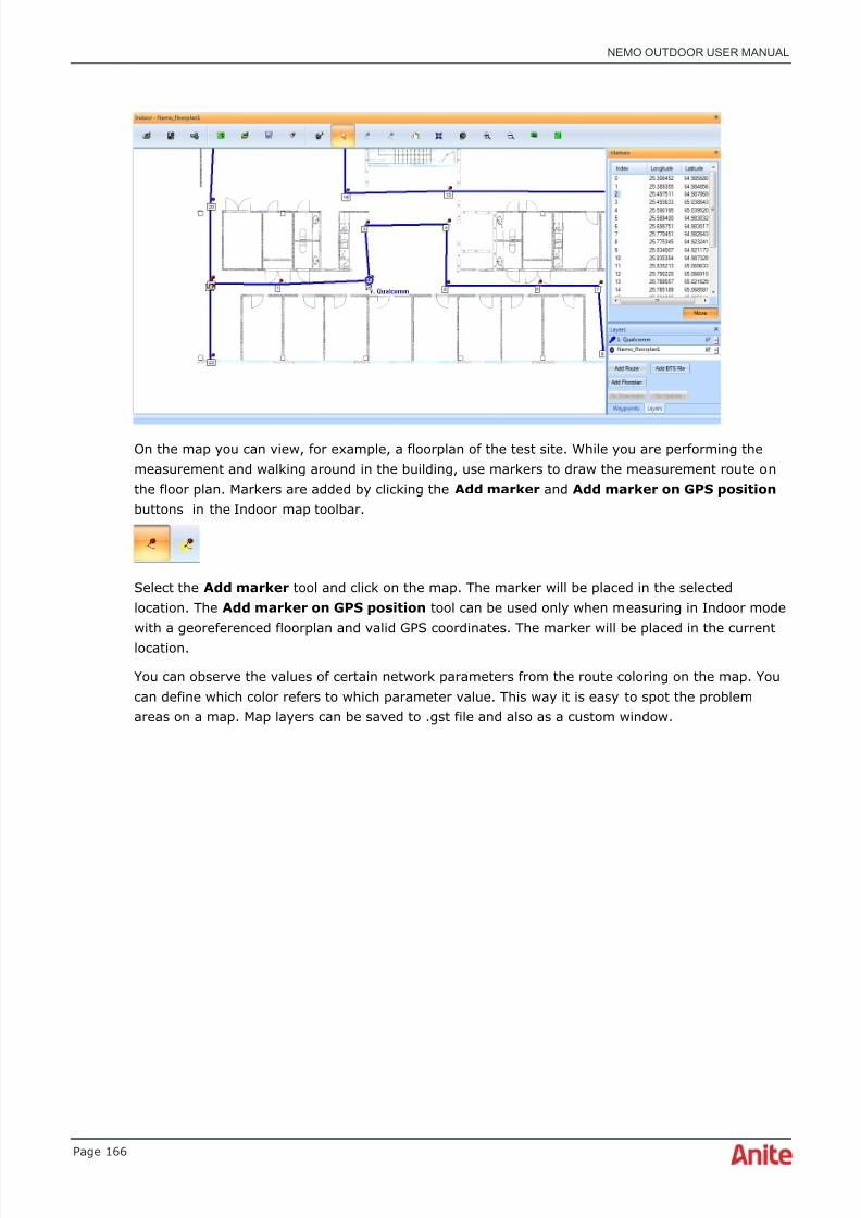
8/16/2019 Nemo Outdoor User Manual
http://slidepdf.com/reader/full/nemo-outdoor-user-manual 166/391
NEMO OUTDOOR USER MANUAL
Page 166
On the map you can view, for example, a floorplan of the test site. While you are performing themeasurement and walking around in the building, use markers to draw the measurement route onthe floor plan. Markers are added by clicking the Add marker and Add marker on GPS position buttons in the Indoor map toolbar.
Select the Add marker tool and click on the map. The marker will be placed in the selectedlocation. The Add marker on GPS position tool can be used only when measuring in Indoor modewith a georeferenced floorplan and valid GPS coordinates. The marker will be placed in the currentlocation.
You can observe the values of certain network parameters from the route coloring on the map. Youcan define which color refers to which parameter value. This way it is easy to spot the problemareas on a map. Map layers can be saved to .gst file and also as a custom window.

8/16/2019 Nemo Outdoor User Manual
http://slidepdf.com/reader/full/nemo-outdoor-user-manual 167/391
NEMO OUTDOOR USER MANUAL
Page 167
6.16.2 Floorplans and BTS files
You can also use BTS files on indoor maps. DAS and small cell BTS types are also supported.
Open a route on an indoor map. Click the Add BTS File button and browse for a BTS file.
After the BTS file is loaded, select a device that will be connected with the BTS file. Click OK .

8/16/2019 Nemo Outdoor User Manual
http://slidepdf.com/reader/full/nemo-outdoor-user-manual 168/391
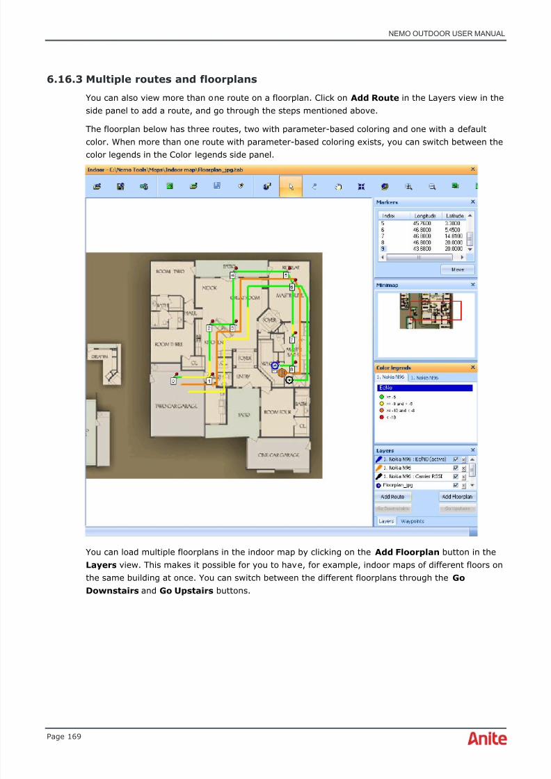
8/16/2019 Nemo Outdoor User Manual
http://slidepdf.com/reader/full/nemo-outdoor-user-manual 169/391
NEMO OUTDOOR USER MANUAL
Page 169
6.16.3 Multiple routes and floorplans
You can also view more than one route on a floorplan. Click on Add Route in the Layers view in theside panel to add a route, and go through the steps mentioned above.
The floorplan below has three routes, two with parameter-based coloring and one with a defaultcolor. When more than one route with parameter-based coloring exists, you can switch between thecolor legends in the Color legends side panel.
You can load multiple floorplans in the indoor map by clicking on the Add Floorplan button in theLayers view. This makes it possible for you to have, for example, indoor maps of different floors onthe same building at once. You can switch between the different floorplans through the GoDownstairs and Go Upstairs buttons.
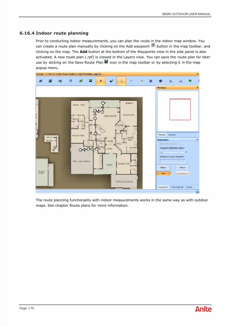
8/16/2019 Nemo Outdoor User Manual
http://slidepdf.com/reader/full/nemo-outdoor-user-manual 170/391
NEMO OUTDOOR USER MANUAL
Page 170
6.16.4 Indoor route planning
Prior to conducting indoor measurements, you can plan the route in the indoor map window. Youcan create a route plan manually by clicking on the Add waypoint button in the map toolbar, andclicking on the map. The Add button at the bottom of the Waypoints view in the side panel is also
activated. A new route plan (.rpf) is viewed in the Layers view. You can save the route plan for lateruse by clicking on the Save Route Plan icon in the map toolbar or by selecting it in the mappopup menu.
The route planning functionality with indoor measurements works in the same way as with outdoormaps. See chapter Route plans for more information.
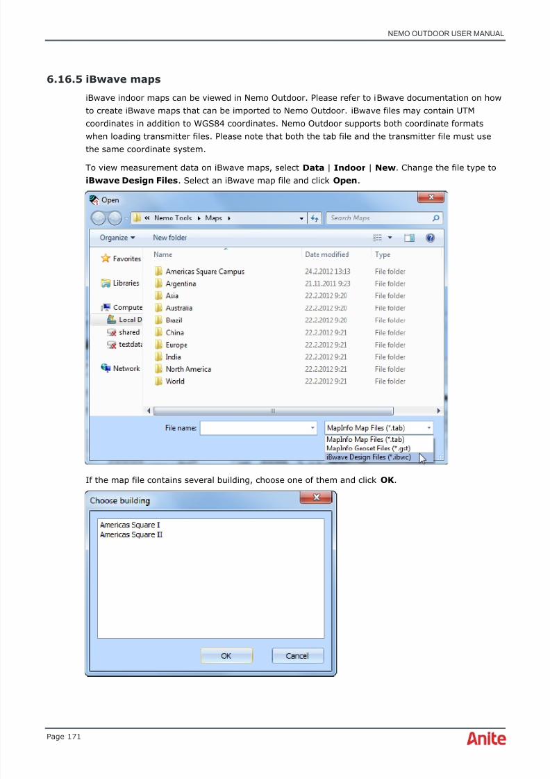
8/16/2019 Nemo Outdoor User Manual
http://slidepdf.com/reader/full/nemo-outdoor-user-manual 171/391
NEMO OUTDOOR USER MANUAL
Page 171
6.16.5 iBwave maps
iBwave indoor maps can be viewed in Nemo Outdoor. Please refer to iBwave documentation on howto create iBwave maps that can be imported to Nemo Outdoor. iBwave files may contain UTMcoordinates in addition to WGS84 coordinates. Nemo Outdoor supports both coordinate formats
when loading transmitter files. Please note that both the tab file and the transmitter file must usethe same coordinate system.
To view measurement data on iBwave maps, select Data | Indoor | New . Change the file type toiBwave Design Files . Select an iBwave map file and click Open .
If the map file contains several building, choose one of them and click OK .
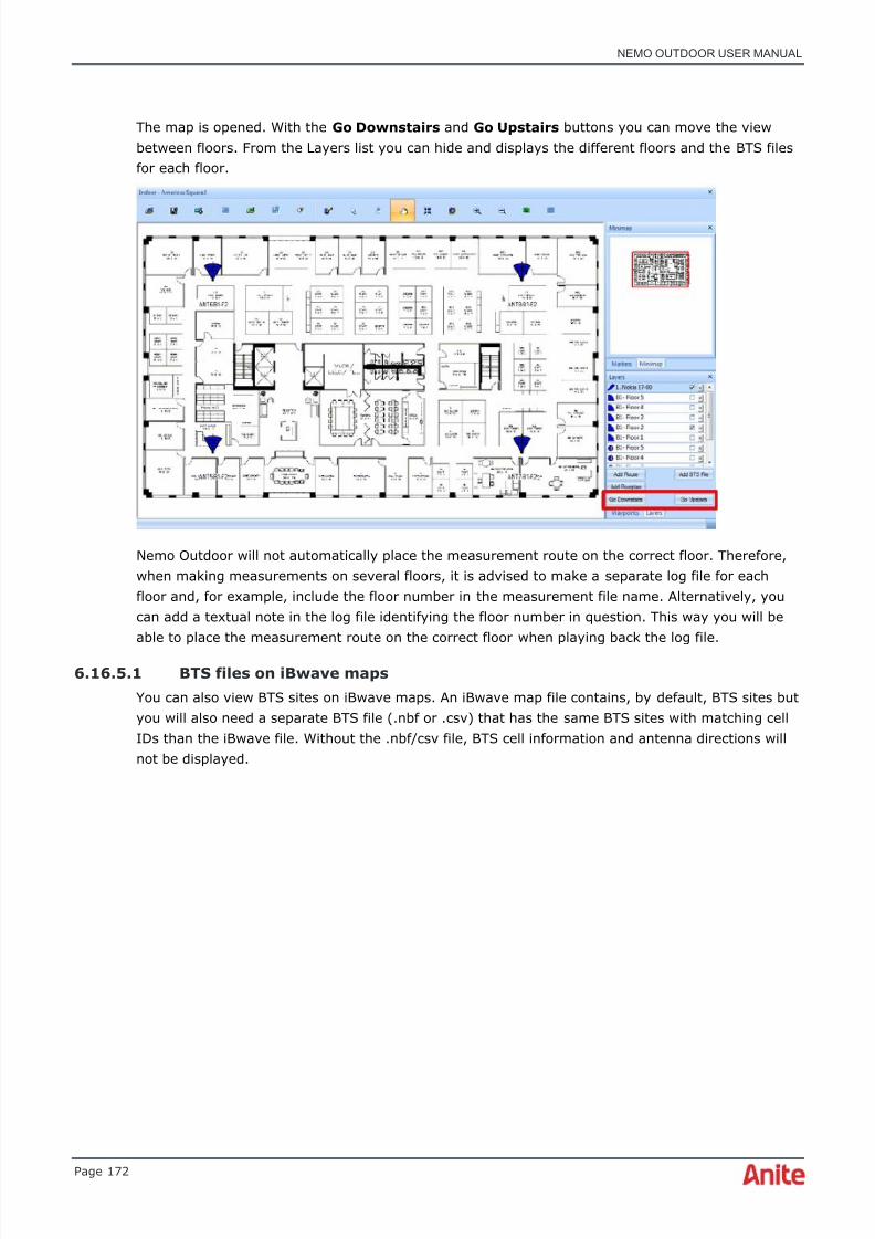
8/16/2019 Nemo Outdoor User Manual
http://slidepdf.com/reader/full/nemo-outdoor-user-manual 172/391
NEMO OUTDOOR USER MANUAL
Page 172
The map is opened. With the Go Downstairs and Go Upstairs buttons you can move the viewbetween floors. From the Layers list you can hide and displays the different floors and the BTS filesfor each floor.
Nemo Outdoor will not automatically place the measurement route on the correct floor. Therefore,when making measurements on several floors, it is advised to make a separate log file for eachfloor and, for example, include the floor number in the measurement file name. Alternatively, youcan add a textual note in the log file identifying the floor number in question. This way you will beable to place the measurement route on the correct floor when playing back the log file.
6.16.5.1 BTS files on iBwave maps
You can also view BTS sites on iBwave maps. An iBwave map file contains, by default, BTS sites butyou will also need a separate BTS file (.nbf or .csv) that has the same BTS sites with matching cellIDs than the iBwave file. Without the .nbf/csv file, BTS cell information and antenna directions willnot be displayed.

8/16/2019 Nemo Outdoor User Manual
http://slidepdf.com/reader/full/nemo-outdoor-user-manual 173/391
NEMO OUTDOOR USER MANUAL
Page 173
First open an iBwave map and click the Add BTS File button to open the BTS file.
Select the BTS file and then select the device connected with the map. Click OK .
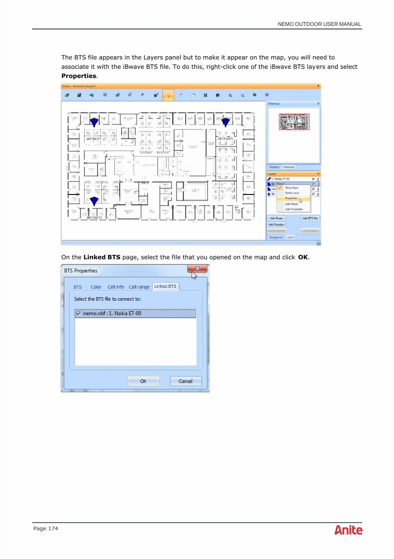
8/16/2019 Nemo Outdoor User Manual
http://slidepdf.com/reader/full/nemo-outdoor-user-manual 174/391
NEMO OUTDOOR USER MANUAL
Page 174
The BTS file appears in the Layers panel but to make it appear on the map, you will need toassociate it with the iBwave BTS file. To do this, right-click one of the iBwave BTS layers and selectProperties .
On the Linked BTS page, select the file that you opened on the map and click OK .

8/16/2019 Nemo Outdoor User Manual
http://slidepdf.com/reader/full/nemo-outdoor-user-manual 175/391
NEMO OUTDOOR USER MANUAL
Page 175
The BTS sites and cell information are now displayed on the map.
6.16.6 DAS anomaly analysis
With DAS anomaly analysis, user can check and verify in-building small cells and DAS (DistributedAntenna Systems) antennas giving simple pass, fail, or untested results for each cell.
Indoor small cell antennas and transmitters can be displayed on the indoor map with iBwave indoorplans and Nemo BTS files (.nbf). DAS anomaly analysis is enabled from BTS Properties.
En a b l e D A S a n o m a l y a n a l y s i s by selecting a device in the field.
Ce l l t e s t r a d i u s in meters defines how close the marker needs to be to the cell in order to perform
the DAS anomaly analysis.

8/16/2019 Nemo Outdoor User Manual
http://slidepdf.com/reader/full/nemo-outdoor-user-manual 176/391
NEMO OUTDOOR USER MANUAL
Page 176
Ce l l t r a n s p a r e n c y defines how the circle is drawn. 0% is almost solid color and 100% istransparent.
S i g n a l le v e l l im i t s (dBm) defines the pass/fail limit for signal level for each system. If the signallevel is above the defined limit, the test result is passed and if the signal level is below the limit, the
test result is failed.
Ce l l se a r c h m o d e defines on which sites the test is performed.
• Full : Requires that the BTS file contains the system, channel number, and scrambling codeinformation.
• System and channel : Requires that the BTS file contains the system and channel numberinformation. Use this option with iBwave map files or if the BTS (.nbf) file does not includethe correct cell type information.
• System : Requires that the BTS file contains the system information. Use this option withiBwave map files or if the BTS (.nbf) file does not include the correct cell type information.
When the analysis is enabled, a circle is drawn around DAS and small cell cells. The color of thecircle depends on the cell test status:
• Untested = gray
• Failed = red
• Passed = green
Whenever a marker is placed within the test radius of the serving cell location, the current signallevel of the serving cell is checked. If the signal level exceeds the defined limit (signal level limitdefined in the BTS Properties dialog), the cell is considered as passed (green) and if the signal level
is below the configured limit, the cell is considered as failed (red).
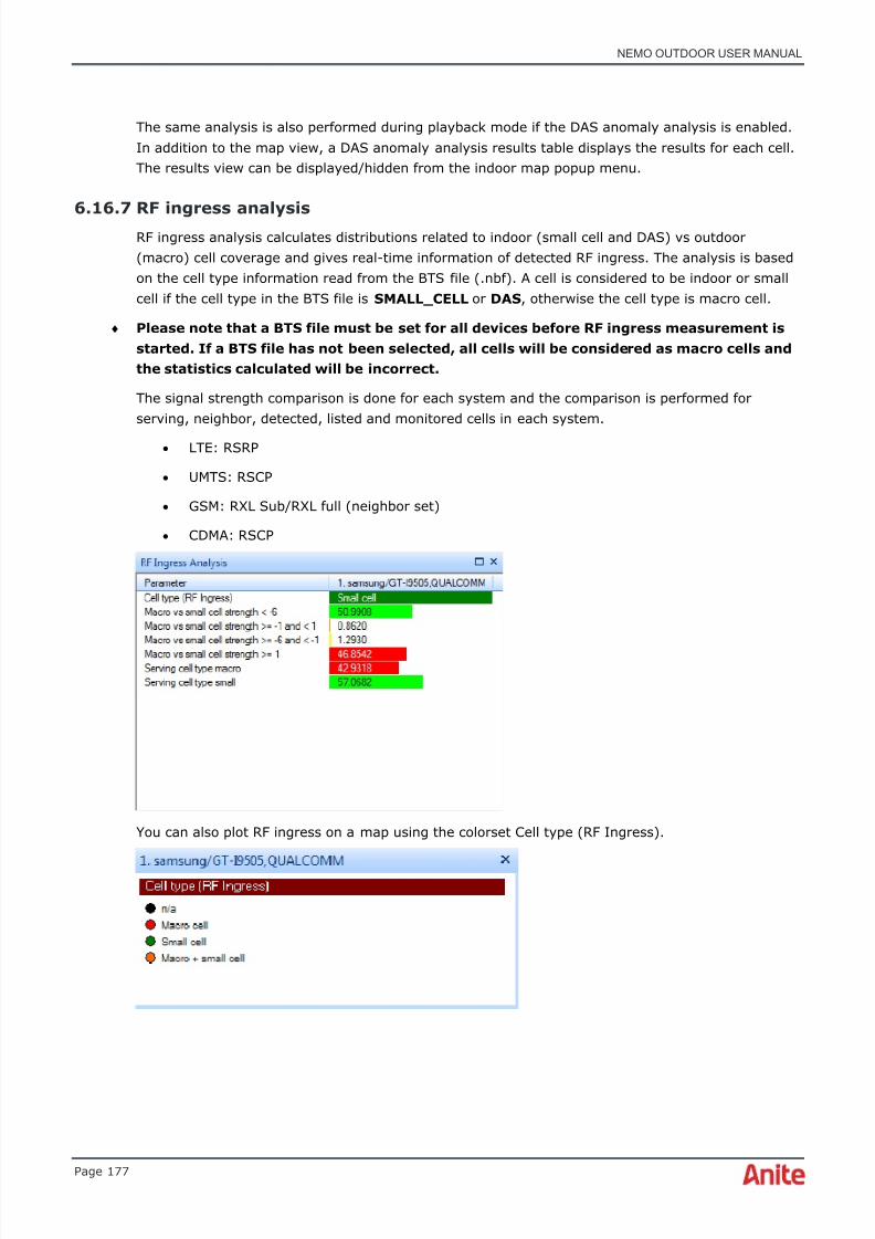
8/16/2019 Nemo Outdoor User Manual
http://slidepdf.com/reader/full/nemo-outdoor-user-manual 177/391
NEMO OUTDOOR USER MANUAL
Page 177
The same analysis is also performed during playback mode if the DAS anomaly analysis is enabled.In addition to the map view, a DAS anomaly analysis results table displays the results for each cell.The results view can be displayed/hidden from the indoor map popup menu.
6.16.7 RF ingress analysis
RF ingress analysis calculates distributions related to indoor (small cell and DAS) vs outdoor(macro) cell coverage and gives real-time information of detected RF ingress. The analysis is basedon the cell type information read from the BTS file (.nbf). A cell is considered to be indoor or smallcell if the cell type in the BTS file is SMALL_CELL or DAS , otherwise the cell type is macro cell.
♦ Please note that a BTS file must be set for all devices before RF ingress measurement isstarted. If a BTS file has not been selected, all cells will be considered as macro cells andthe statistics calculated will be incorrect.
The signal strength comparison is done for each system and the comparison is performed forserving, neighbor, detected, listed and monitored cells in each system.
• LTE: RSRP
• UMTS: RSCP
• GSM: RXL Sub/RXL full (neighbor set)
• CDMA: RSCP
You can also plot RF ingress on a map using the colorset Cell type (RF Ingress).
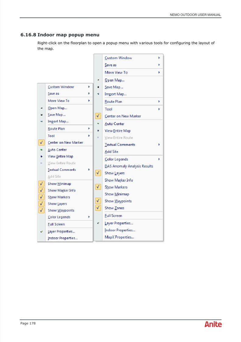
8/16/2019 Nemo Outdoor User Manual
http://slidepdf.com/reader/full/nemo-outdoor-user-manual 178/391
NEMO OUTDOOR USER MANUAL
Page 178
6.16.8 Indoor map popup menu
Right-click on the floorplan to open a popup menu with various tools for configuring the layout ofthe map.

8/16/2019 Nemo Outdoor User Manual
http://slidepdf.com/reader/full/nemo-outdoor-user-manual 179/391
NEMO OUTDOOR USER MANUAL
Page 179
6.16.8.1 Custom Window Properties dialog
In the Custom Window Properties dialog you can define the custom window name and selectgroups for the custom windows. The custom window groups define which custom windows areavailable for each device. For example, if you select LTE FDD, the custom window will only beavailable when an LTE device is added to Nemo Outdoor or you are playing back an LTEmeasurement.
6.16.8.2 Custom window - Save changes
Use the Save Changes command to save changes made in the custom window.
6.16.8.3 Custom window - Save as new custom window
Right-click on a graph window and select Save as New Custom Window from the popup menu.The Custom Window Properties dialog is opened (see above). Type a name for the customwindow and define the custom window groups.
6.16.8.4 Save as - CSV file
Use the Save as CSV File command to export the active view into CSV format. See chapter CSVfile export for more information.
6.16.8.5 Save as - Image
Use the Save as Image command to save the active view as a .jpg image.
6.16.8.6 Save as - MapInfo Tab-file
Use the Save as MapInfo Tab-File command to export the active view into MapInfo format. Seechapter MapInfo Tab-file export for more information.

8/16/2019 Nemo Outdoor User Manual
http://slidepdf.com/reader/full/nemo-outdoor-user-manual 180/391
NEMO OUTDOOR USER MANUAL
Page 180
6.16.8.7 Move view to
With the Move View To command you can move the active view to another view group. Seechapter View groups for more information on view groups.
6.16.8.8 Open map
By selecting the Open Map item, you can open existing map files (.tab).
6.16.8.9 Save map
By selecting the Save Map item, you can open the Save As dialog that you can use for saving themap with another name.
6.16.8.10 Import map
You can import your own bitmap files to Nemo Outdoor and use them as indoor maps. Click theImport Map button in the map toolbar or select Import Map from the Data | Indoor menu. Selectan image file and click Open . The Map Import Parameters dialog is opened.
In order for the map and route drawing to function correctly, you need to georegister the image fileor enter the exact dimensions of the map area.

8/16/2019 Nemo Outdoor User Manual
http://slidepdf.com/reader/full/nemo-outdoor-user-manual 181/391

8/16/2019 Nemo Outdoor User Manual
http://slidepdf.com/reader/full/nemo-outdoor-user-manual 182/391
NEMO OUTDOOR USER MANUAL
Page 182
6.16.8.14 Save as MapInfo Tab-file
Use the Save as MapInfo Tab-File command to export the active view into MapInfo format. Seechapter MapInfo Tab-file export for more information.
6.16.8.15 Add waypoints
Activates the add waypoint functionality for creating route plans manually.
6.16.8.16 Tool
The Tool pull-down menu offers a selection of settings for configuring the window setup. With theAdd Marker command you can add markers in the measurement file. The Arrow selection changesthe cursor back to an arrow. The Pan selection changes the cursor into a hand that can scroll themap. The Center selection allows the map to be centered according to the cursor point. The ZoomIn and Zoom Out selections change the cursor into a magnifying glass. You can also zoom in andout using the mouse wheel. The Clear Route command removes the measurement route from themap. Note that this command is activated only during measurements. It cannot be used duringplayback.
6.16.8.17 Center on new marker
The Center on New Marker option defines whether the indoor view is centered on a marker whenit is inserted.
6.16.8.18 Auto center
The Auto Center tool for MapInfo® pans the map so that the current location will stay on thevisible area of the map. Note that you cannot use the Pan and Center tools when the Auto Center command is selected.
6.16.8.19 View entire map
The View Entire Map command displays the whole map.
6.16.8.20 View entire routeThe View Entire Route command displays the whole route.
6.16.8.21 Textual comments
With the Textual Comments tool you can add textual comments on the map. Select Add TextualComment from the menu and type in the text box that appears on the map. The box can berepositioned by dragging it on the map. To remove or edit individual comments, right-click on thetext box and select Remove or Edit . To remove all comments, right-click on the map and selectTextual Comments | Remove All Textual Comments .
8/16/2019 Nemo Outdoor User Manual
http://slidepdf.com/reader/full/nemo-outdoor-user-manual 183/391
NEMO OUTDOOR USER MANUAL
Page 183
6.16.8.22 Add site
With the Add Site tool you can edit and add new BTS sites on the map. Please see chapter EditingBTS files in Nemo Outdoor for more information.
6.16.8.23 Color legends
Color Legend displays the name of the selected Color Set on the map window.
6.16.8.24 DAS anomaly analysis results
When perfoming DAS anomaly analysis, the DAS anomaly analysis results table displays the resultsfor each cell. This command hides/displays the results view.
6.16.8.25 Show layers
Selecting the Show Layers item in the popup menu will display the Layers view in the side panel.
6.16.8.26 Show marker info
Show marker info hides or displays markers inserted into the measurement file.
6.16.8.27 Show markers
Show Markers hides or displays markers on a map.
6.16.8.28 Show minimap
With the Show Minimap command you can view and hide the Minimap in the Indoor window.Minimap displays a miniature version of the map and the current location is highlighted with a redsquare.
6.16.8.29 Show waypoints
The waypoints item will activate the free route planning functionality on the map. You can createand save a route plan for later use. See chapter Creating and modifying route plans with waypointsfor more information.

8/16/2019 Nemo Outdoor User Manual
http://slidepdf.com/reader/full/nemo-outdoor-user-manual 184/391
NEMO OUTDOOR USER MANUAL
Page 184
6.16.8.30 Show zones
You can view zones on iBwave maps. Zones in iBwave files are defined as MapInfo mif/mid files.Right-click on the map and select Show Zones to display/hide the zones on the floorplan. Click ona zone with the arrow tool to select the zone (the map is zoomed to the zone and the zone is drawn
less transparent).
6.16.8.31 Full screen
Full Screen switches the Indoor map view to full screen. Close the full screen view by clicking onClose Full Screen in the popup window that appears.
6.16.8.32 Layer Properties – Indoor map
In the Route Properties dialog, you can define map-related settings. See chapter Route propertiesfor more information.
6.16.8.33 Indoor Properties dialog

8/16/2019 Nemo Outdoor User Manual
http://slidepdf.com/reader/full/nemo-outdoor-user-manual 185/391
NEMO OUTDOOR USER MANUAL
Page 185
O f fs e t b e t w e e n r o u t e s defines the offset (in pixels) between routes on an indoor map. This valueis used with multi measurements where you have multiple routes which, without offset, wouldoverlap each other. You can also disable the default offset completely. To define offset values forindividual routes, go to the Route Properties dialog and define the X and Y offset values.
With the Sa v e m a r k e r s i n l a t / l o n f o r m a t w h e n t h e f l o o r p l a n u s e s U TM c o o r d i n a t es optionyou can select to save markers in GPS (lat/lon) WGS84 format when the iBwave map file has UTMcoordinates. The coordinate system used is saved to the marker file. In playback mode, thecoordinate system is detected when loading marker files so that both WGS84 and UTM formatmarker files are displayed correctly.
6.16.8.34 MapX Properties dialog
Click the MapX Properties button to define some MapX specific properties. Note that thesesettings differ according to the map provider. These settings can be saved in a MapInfo Geoset fileby clicking the Save Map button in the Map window. To later open the .gst file, click the Open Mapbutton, select MapInfo Geoset file in the Files of Type listbox, and select a file from the list.
If you are using MapInfo® maps, you can define the appearance of the map even further byclicking the MapX Properties button in the Route Properties dialog. In the Layers tab the tableshows a list of the current layers. The order on the list defines the order in which the layers aredisplayed on a map; for example, in this case the Route layer is on the top, Current Position layer isunder that, and World map is at the bottom. This utility is useful if you want to have a bigger mapon the bottom (e.g., a map of Europe) and a more detailed map of a smaller area (e.g., of Helsinki)on top of that. To add layers on the map click Add . An Open dialog is opened where you can choosethe map you want to add as a layer. The map is added on the list and with the Up and Down youcan change the map’s position on the list. By selecting and clearing the Visible option you candecide whether or not to display the layer on the map. To remove layers from the map, select thelayer from the list and click the Remove button.
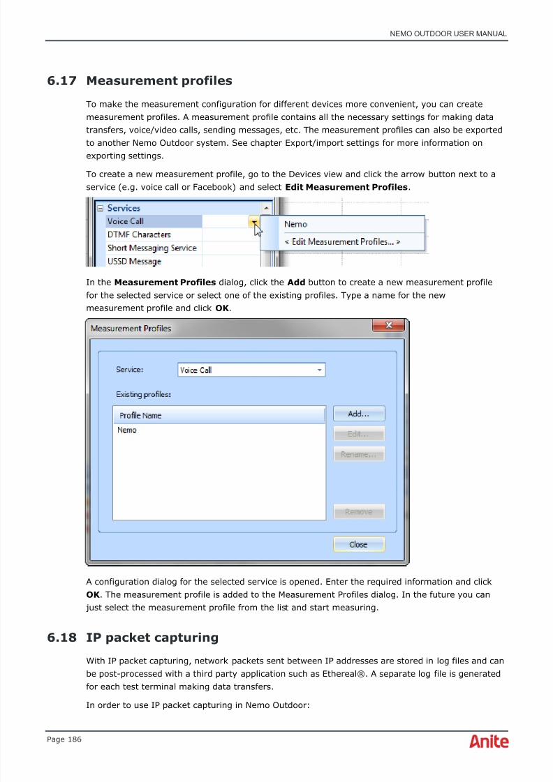
8/16/2019 Nemo Outdoor User Manual
http://slidepdf.com/reader/full/nemo-outdoor-user-manual 186/391
NEMO OUTDOOR USER MANUAL
Page 186
6.17 Measurement profiles
To make the measurement configuration for different devices more convenient, you can createmeasurement profiles. A measurement profile contains all the necessary settings for making datatransfers, voice/video calls, sending messages, etc. The measurement profiles can also be exportedto another Nemo Outdoor system. See chapter Export/import settings for more information onexporting settings.
To create a new measurement profile, go to the Devices view and click the arrow button next to aservice (e.g. voice call or Facebook) and select Edit Measurement Profiles .
In the Measurement Profiles dialog, click the Add button to create a new measurement profilefor the selected service or select one of the existing profiles. Type a name for the newmeasurement profile and click OK .
A configuration dialog for the selected service is opened. Enter the required information and clickOK . The measurement profile is added to the Measurement Profiles dialog. In the future you can
just select the measurement profile from the list and start measuring.
6.18 IP packet capturing
With IP packet capturing, network packets sent between IP addresses are stored in log files and canbe post-processed with a third party application such as Ethereal®. A separate log file is generated
for each test terminal making data transfers.
In order to use IP packet capturing in Nemo Outdoor:

8/16/2019 Nemo Outdoor User Manual
http://slidepdf.com/reader/full/nemo-outdoor-user-manual 187/391
NEMO OUTDOOR USER MANUAL
Page 187
1. First, install Microsoft Network Monitor. Go to Microsoft website to download the freeNetwork Monitor installation package. Select the NM34_x86.exe (for 32-bit Windows) orNM34_x64.exe (for 64-bit Windows) installation file and click on Download .
2. Once the installation file is downloaded, double-click on it. The Microsoft Network Monitor
3.4 dialog appears. Click Yes to continue installation and follow the steps in the installationwizard to finish the installation.
3. Next, install Nemo Outdoor .
4. For 64-bit Windows you need to install an additional setup of Nemo Packet Monitor x647.x.x.exe (Nemo Outdoor and Nemo Packet Monitor must be of the same version) found inthe Nemo Outdoor product package. Double-click the file and follow the steps in theinstallation wizard to finish the installation.
5. Start Nemo Outdoor, add a device, and go to the Measurement Properties ,Measurement page. Select the Enable IP Capture option.
♦ Note that if the Enable IP Capture item is not on the list, the Network Monitor driver isnot installed.
IP packet capture measurement option has several states:
• Disabled : IP packet monitoring is not performed at all
• Enabled : a separate .pcap file is not written but, for example, KPI, IP service access time isrecorded
• Partial logging : only message headers are recorded
• Full logging : all messages are recorded
The IP packet data is stored in a separate file (.pcap) for each measurement terminal for which IPcapturing is enabled.
To view data in Packet decoder grids during playback, you need to enable the packet decodingfunction prior to performing data measurements. Select Full logging in the Enable IP Capture
field. A separate .pcap-file will be generated for the measurement. This file needs to accompany themeasurement file in the same folder when viewing and decoding packet capture information inPacket Decoder grids in Nemo Outdoor.
6.19 Making script files
♦ Note that it is not possible to use scripts with scanners.
The script file is an ASCII file containing the list of numbers that are to be called. The extension forscript files is .nsfx or .nsf (old script format). You can edit the Script file configuration in the ScriptEditor dialog. When editing scripts, it is possible to have several Script Editor dialogs open and to
copy and paste commands from one script to another.
You can access this dialog by selecting Measurement | Script Editor (Ctrl+E).
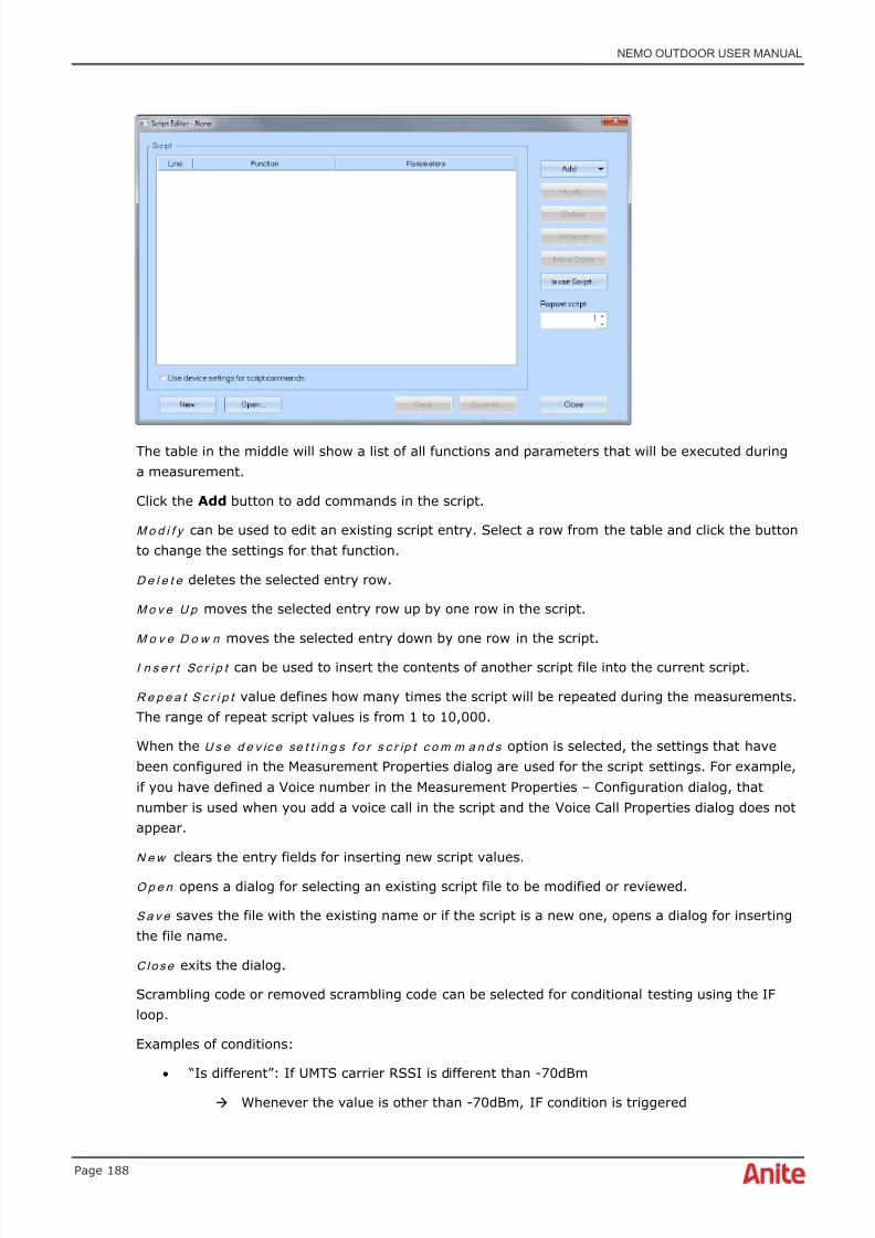
8/16/2019 Nemo Outdoor User Manual
http://slidepdf.com/reader/full/nemo-outdoor-user-manual 188/391
NEMO OUTDOOR USER MANUAL
Page 188
The table in the middle will show a list of all functions and parameters that will be executed duringa measurement.
Click the Add button to add commands in the script.
M o d i f y can be used to edit an existing script entry. Select a row from the table and click the buttonto change the settings for that function.
D e l e t e deletes the selected entry row.
M o v e U p moves the selected entry row up by one row in the script.
M o v e D o w n moves the selected entry down by one row in the script.
I n s e r t Sc r i p t can be used to insert the contents of another script file into the current script.
R e p e a t S c r i p t value defines how many times the script will be repeated during the measurements.The range of repeat script values is from 1 to 10,000.
When the U s e d e v ic e se t t i n g s f o r s c r ip t c o m m a n d s option is selected, the settings that havebeen configured in the Measurement Properties dialog are used for the script settings. For example,if you have defined a Voice number in the Measurement Properties – Configuration dialog, thatnumber is used when you add a voice call in the script and the Voice Call Properties dialog does notappear.
N e w clears the entry fields for inserting new script values.
O p e n opens a dialog for selecting an existing script file to be modified or reviewed.
S a v e saves the file with the existing name or if the script is a new one, opens a dialog for insertingthe file name.
C l o s e exits the dialog.
Scrambling code or removed scrambling code can be selected for conditional testing using the IFloop.
Examples of conditions:
• “Is different”: If UMTS carrier RSSI is different than -70dBm
Whenever the value is other than -70dBm, IF condition is triggered

8/16/2019 Nemo Outdoor User Manual
http://slidepdf.com/reader/full/nemo-outdoor-user-manual 189/391
NEMO OUTDOOR USER MANUAL
Page 189
• “Is changed”: If UMTS carrier RSSI is changed
Whenever the UMTS carrier RSSI value changes, the IF condition is triggered. Thereference value is unknown, which means that when starting the measurement andwhen the first UMTS carrier RSSI value is received, the IF condition is triggered. The
next trigger occurs when the carrier RSSI value is different from the previous value.For example,
Carrier RSSI value in the log file: -70dBm triggers the IF string
Carrier RSSI value -70dBm nothing happens
Carrier RSSI value -68dBm Triggers the IF string
6.19.1 Script transfer stop commands
With the forced stop command it is possible to abort a current script command. For example, a datatransfer can be canceled if the serving system changes, instead of waiting for its completion. It is
also possible to set a time duration for data transfers. If a data transfer is not completed during auser-defined time, the Nemo Outdoor application will abort the data transfer automatically. Pleasenote that in this case the data disconnection status is written as Normal data disconnect .
The forced stop command, e.g., with voice calls, can be used in conjunction with conditional or waitcommands as well. For example, if a call should be stopped when the system changes from GSM toUMTS, the forced stop command can be used to end the call immediately after the system changes.In the example below, the voice call is started only when the serving system is GSM. Call durationis set to 120 seconds. It should be noted that the actual call duration is set with line three, Waituntil system is UMTS but at most 120s . After the call is connected, the script starts waiting forthe system to be changed to UMTS, or at most 120 seconds. The call is ended with End a voicecall (forced) with line 4 after 120 seconds, or when system changes to UMTS; whichever comesfirst.
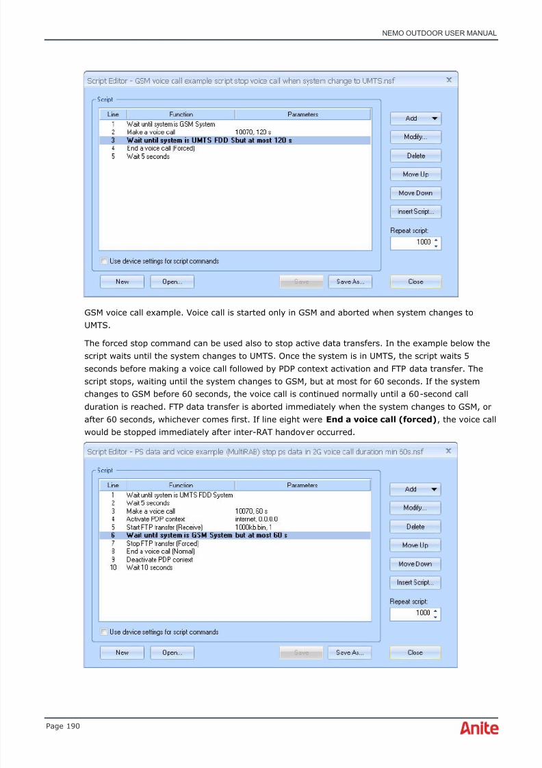
8/16/2019 Nemo Outdoor User Manual
http://slidepdf.com/reader/full/nemo-outdoor-user-manual 190/391

8/16/2019 Nemo Outdoor User Manual
http://slidepdf.com/reader/full/nemo-outdoor-user-manual 191/391
NEMO OUTDOOR USER MANUAL
Page 191
In the following you will see a PS data and voice call example. The data transfer is aborted whenthe system changes to GSM, or after 60 seconds; voice call is continued. The call duration is 60seconds.
In the following you will see another PS data and voice call example. The data transfer and voicecall are aborted when the system changes to GSM, or after 60 seconds, whichever comes first.
The voice call is aborted when the system changes to GSM, or after 60 seconds, but data transfer iscontinued normally with the Stop FTP transfer (Normal) command.
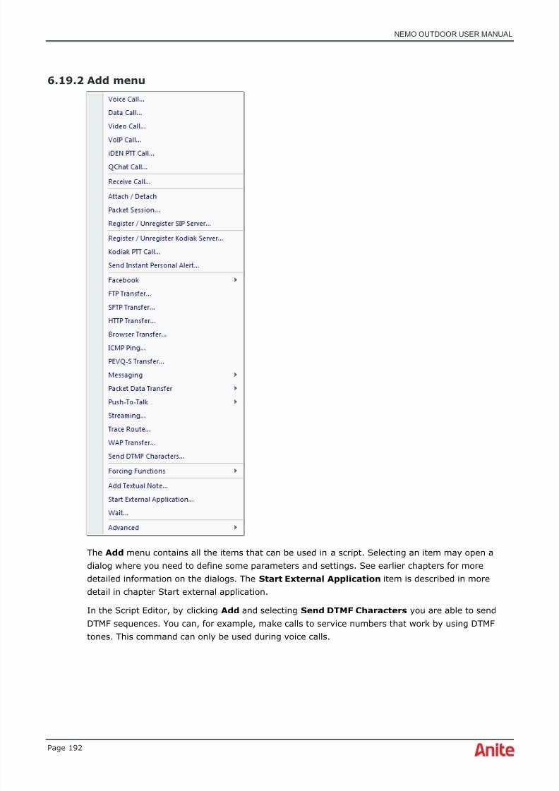
8/16/2019 Nemo Outdoor User Manual
http://slidepdf.com/reader/full/nemo-outdoor-user-manual 192/391
NEMO OUTDOOR USER MANUAL
Page 192
6.19.2 Add menu
The Add menu contains all the items that can be used in a script. Selecting an item may open adialog where you need to define some parameters and settings. See earlier chapters for moredetailed information on the dialogs. The Start External Application item is described in moredetail in chapter Start external application.
In the Script Editor, by clicking Add and selecting Send DTMF Characters you are able to sendDTMF sequences. You can, for example, make calls to service numbers that work by using DTMFtones. This command can only be used during voice calls.
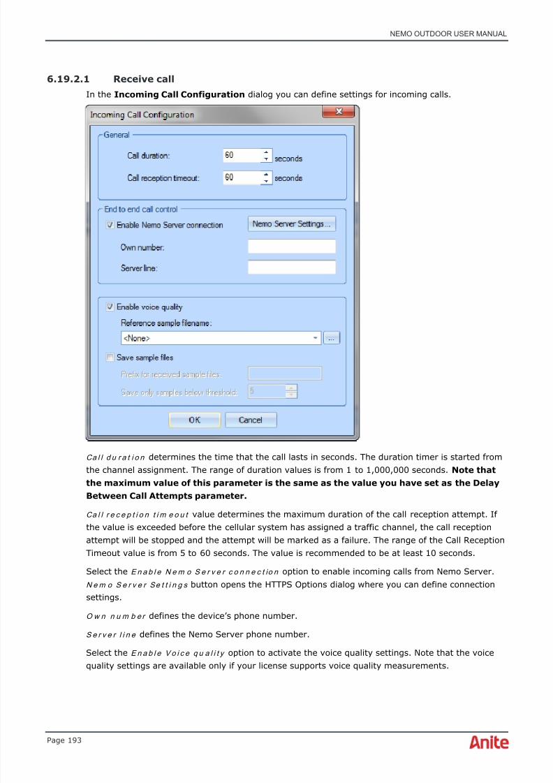
8/16/2019 Nemo Outdoor User Manual
http://slidepdf.com/reader/full/nemo-outdoor-user-manual 193/391
NEMO OUTDOOR USER MANUAL
Page 193
6.19.2.1 Receive call
In the Incoming Call Configuration dialog you can define settings for incoming calls.
Ca l l d u r a t i o n determines the time that the call lasts in seconds. The duration timer is started fromthe channel assignment. The range of duration values is from 1 to 1,000,000 seconds. Note thatthe maximum value of this parameter is the same as the value you have set as the DelayBetween Call Attempts parameter.
Ca l l r e c e p t i o n t i m e o u t value determines the maximum duration of the call reception attempt. Ifthe value is exceeded before the cellular system has assigned a traffic channel, the call receptionattempt will be stopped and the attempt will be marked as a failure. The range of the Call ReceptionTimeout value is from 5 to 60 seconds. The value is recommended to be at least 10 seconds.
Select the E n a b l e N e m o S e r v e r c o n n e c t io n option to enable incoming calls from Nemo Server.
N e m o S e r v e r Se t t i n g s button opens the HTTPS Options dialog where you can define connectionsettings.
O w n n u m b e r defines the device’s phone number.
S e r v e r l i n e defines the Nemo Server phone number.
Select the E n a b l e Vo i c e q u a l i t y option to activate the voice quality settings. Note that the voicequality settings are available only if your license supports voice quality measurements.

8/16/2019 Nemo Outdoor User Manual
http://slidepdf.com/reader/full/nemo-outdoor-user-manual 194/391
NEMO OUTDOOR USER MANUAL
Page 194
R e f e r e n c e s a m p l e f il e n a m e defines the reference sample to which the received audio sample iscompared. If you want to use your own test samples, make sure that the samples are of 8KHzsampling rate, 16-bit linear coded .wav files that are no longer than six seconds in length. With theTerratec sound card, sampling rate can be 8kHz or 16 kHz (for WB-AMR testing) and sample lengtha maximum of 30 seconds. For ECHO measurements, use one of the following samples: 10s.wav,4s_m.wav, 8s.wav, ru_6s.wav, and ru_6s_wb.wav.
Select the S a v e s a m p l e f i l e s option to save the received voice quality sample files.
P r e f i x f o r r e c e i v e d s a m p l e f i le s refers to the prefix that is added to the file names of receivedaudio sample files. If you leave this field empty, the received audio files are not stored. When aprefix is defined, Nemo Outdoor names the files as follows: prefix_mos_date_time.wav where prefixis the user-defined prefix, mos the voice quality score on a MOS scale with one decimal precisionbut without decimal point, date in DDMMYYYY format, and time in HHMMSS format. For example:terminal1_34_15112004_143045.wav.
Sa v e o n l y s a m p l e s b e lo w t h r e s h o l d determines the value below which the samples are saved.The threshold values range from 0-5, 0 being the worst and 5 the best value. The default thresholdvalue is 5, which means that all samples are saved.
♦ Note that the Script Settings table is activated only if you access this dialog through theScript Editor.
♦ Note that with voice quality measurements when calling the Nemo audio server, thedelay time between a new call attempt and the previous call disconnect must be at least10 seconds.

8/16/2019 Nemo Outdoor User Manual
http://slidepdf.com/reader/full/nemo-outdoor-user-manual 195/391

8/16/2019 Nemo Outdoor User Manual
http://slidepdf.com/reader/full/nemo-outdoor-user-manual 196/391
NEMO OUTDOOR USER MANUAL
Page 196
Both devices have been assigned for the same script group called “PS data”.
Script groups are useful especially if certain devices and when script files are needed to besynchronized. In this example, it is not necessary to use the script group. As many synchronizationpoints as needed can be added to the script files. It should be noted that the number ofsynchronization points between script files used in the same script group should be equal.
With the W a i t F i x e d and R a n d o m options you can define a fixed wait time (in ms) or a randomtime (define the minimum and maximum values in ms) and then select one of the following:
• Cu r r e n t t i m e : wait (fixed or random) is added between items in the script.
• L a s t n o t i f i ca t i o n : wait (fixed or random) is added after the selected notification. Select thenotification from the drop-down menu. For example, you can make the script pause for 60seconds after a call attempt event. This will prevent the script from continuing before the
call attempt has completed. Note that also custom-made notifications can be selected here.• With the Cu s t o m c o n d i t i o n option you can make the script wait for a custom condition.
Click the Edit Rules button to access the Wait Custom Conditions dialog where you candefine a wait condition. For example, you can define a specific parameter value.

8/16/2019 Nemo Outdoor User Manual
http://slidepdf.com/reader/full/nemo-outdoor-user-manual 197/391
NEMO OUTDOOR USER MANUAL
Page 197
• N e x t n o t i f ic a t i o n : script waits for the selected event notification to appear. Select thenotification from the drop-down menu. For example, you can make the script wait until thesystem changes from GSM to UMTS.
• Cu r r e n t s y s t e m i s : script file continues only when the system selected from the drop-down menu is in use.
• B u t a t m o s t value is the maximum wait time in ms if the defined notification does notappear.
Adding a pause in the script file:
1. First define the wait time in ms.
2. Then define from which point onwards the wait time is calculated: from the current time orafter a certain event notification, such as, call attempt.
3. If you selected the Last notification or Next notification option, define also the maximumwait time in ms after which the script will continue.
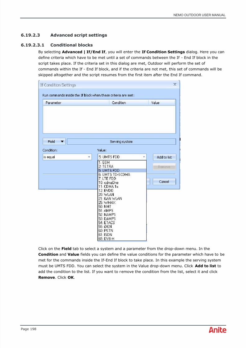
8/16/2019 Nemo Outdoor User Manual
http://slidepdf.com/reader/full/nemo-outdoor-user-manual 198/391
NEMO OUTDOOR USER MANUAL
Page 198
6.19.2.3 Advanced script settings
6.19.2.3.1 Conditional blocks
By selecting Advanced | If/End If , you will enter the If Condition Settings dialog. Here you candefine criteria which have to be met until a set of commands between the If - End If block in thescript takes place. If the criteria set in this dialog are met, Outdoor will perform the set ofcommands within the If - End If block, and if the criteria are not met, this set of commands will beskipped altogether and the script resumes from the first item after the End If command.
Click on the Field tab to select a system and a parameter from the drop-down menu. In theCondition and Value fields you can define the value conditions for the parameter which have to bemet for the commands inside the If-End If block to take place. In this example the serving systemmust be UMTS FDD. You can select the system in the Value drop-down menu. Click Add to list toadd the condition to the list. If you want to remove the condition from the list, select it and clickRemove . Click OK .
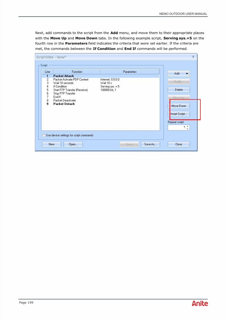
8/16/2019 Nemo Outdoor User Manual
http://slidepdf.com/reader/full/nemo-outdoor-user-manual 199/391
NEMO OUTDOOR USER MANUAL
Page 199
Next, add commands to the script from the Add menu, and move them to their appropriate placeswith the Move Up and Move Down tabs. In the following example script, Serving sys.=5 on thefourth row in the Parameters field indicates the criteria that were set earlier. If the criteria aremet, the commands between the If Condition and End If commands will be performed.

8/16/2019 Nemo Outdoor User Manual
http://slidepdf.com/reader/full/nemo-outdoor-user-manual 200/391
NEMO OUTDOOR USER MANUAL
Page 200
6.19.2.3.2 Loops
You can add loops in the script files. By going to Add | Advanced | Loop/End Loop , you willenter the Loop Settings dialog.
You can select from the following loop options:
• Repeat the loop x times
• Repeat the loop for x minutes
• Repeat the loop until the time is x
• Repeat the loop as long as the following criteria are met
With the Repeat the loop as long as the following criteria are met option you can setconditions for the loop to take place. Click the Field button to select a parameter. Then define the
condition and value for the selected parameter. Finally click Add to list and OK to add the loop inthe script.

8/16/2019 Nemo Outdoor User Manual
http://slidepdf.com/reader/full/nemo-outdoor-user-manual 201/391
NEMO OUTDOOR USER MANUAL
Page 201
In the first example, the loop has been set to be repeated twice before continuing with the script.Click OK and add the wanted script commands in the script from the Add menu. You can move thecommands to their appropriate places with the Move Up and Move Down tabs. In the examplebelow the voice call within the loop will be repeated twice before continuing with the script.
The second loop option allows the user to define criteria which need to be met for the loop to berepeated. In the example below the system and parameter ( UMTS | Ec/N0 (Active) ) have beenselected from the Field drop-down menu. The condition for the loop is that the parameter value
needs to be greater or equal to -5. Click Add to list and OK . The commands inside the loop blockwill be performed only and as long as the Ec/N0 (Active) value is greater or equal to -5 .
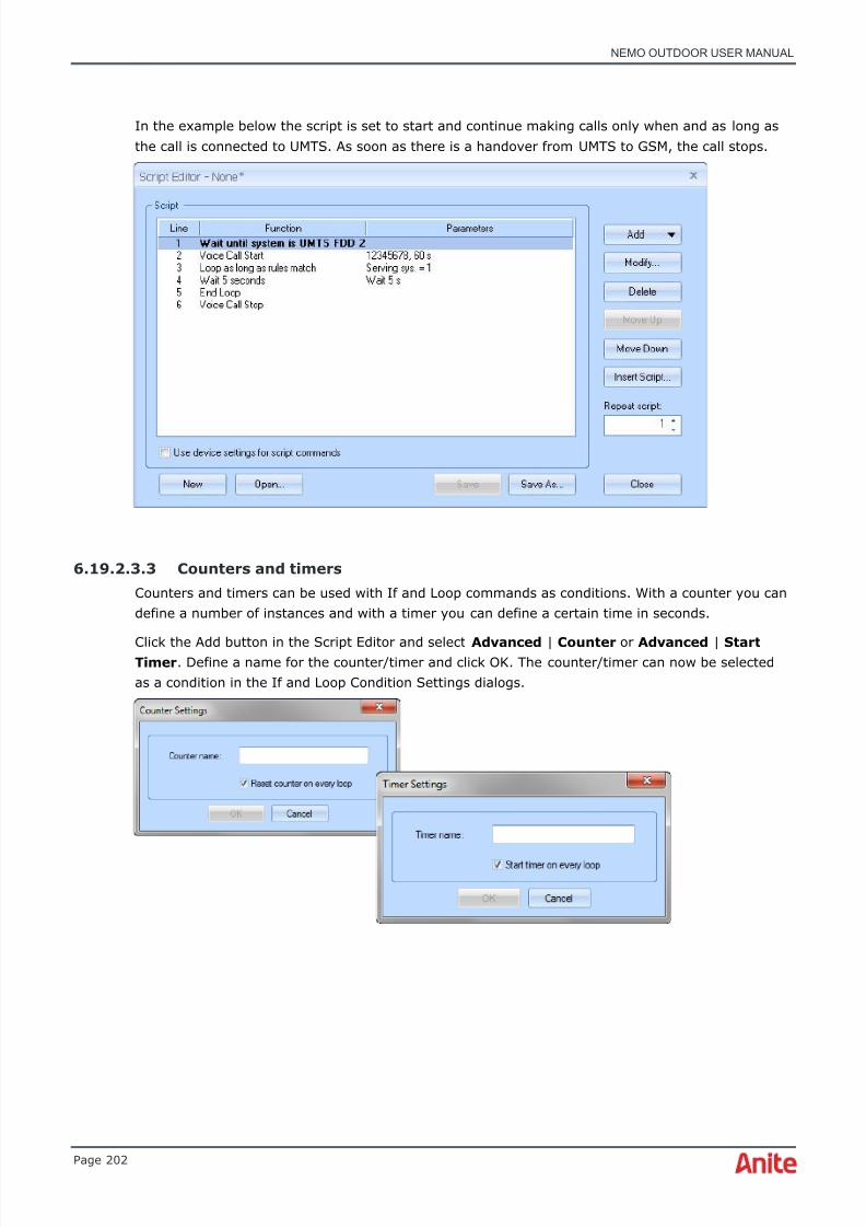
8/16/2019 Nemo Outdoor User Manual
http://slidepdf.com/reader/full/nemo-outdoor-user-manual 202/391
NEMO OUTDOOR USER MANUAL
Page 202
In the example below the script is set to start and continue making calls only when and as long asthe call is connected to UMTS. As soon as there is a handover from UMTS to GSM, the call stops.
6.19.2.3.3 Counters and timers
Counters and timers can be used with If and Loop commands as conditions. With a counter you candefine a number of instances and with a timer you can define a certain time in seconds.
Click the Add button in the Script Editor and select Advanced | Counter or Advanced | StartTimer . Define a name for the counter/timer and click OK. The counter/timer can now be selectedas a condition in the If and Loop Condition Settings dialogs.

8/16/2019 Nemo Outdoor User Manual
http://slidepdf.com/reader/full/nemo-outdoor-user-manual 203/391

8/16/2019 Nemo Outdoor User Manual
http://slidepdf.com/reader/full/nemo-outdoor-user-manual 204/391

8/16/2019 Nemo Outdoor User Manual
http://slidepdf.com/reader/full/nemo-outdoor-user-manual 205/391
NEMO OUTDOOR USER MANUAL
Page 205
Sc h e d u l ed m e a su r e m e n t s displays a list of measurements that will be run when themeasurement list is started. Each measurement will be recorded in its own file. Click Add New toadd new measurements and Remove to delete selected measurements from the list.
Fi l en a m e defines the filename format. The default format is %y%b%d %H%M%S (year-month-day hours-minutes-seconds, e.g., 06May31 165246) but you can use any combination of the itemsbelow. For example, "%y%b%d_%n means that the filename looks as follows: 06May31_1. The lastnumber (%n) is the sequence number for measurement files recorded that day.
%a Abbreviated weekday name
%A Full weekday name
%b Abbreviated month name
%B Full month name
%d Day of month as decimal number (01 – 31)
%H Hour in 24-hour format (00 – 23)
%I Hour in 12-hour format (01 – 12)

8/16/2019 Nemo Outdoor User Manual
http://slidepdf.com/reader/full/nemo-outdoor-user-manual 206/391
NEMO OUTDOOR USER MANUAL
Page 206
%j Day of year as decimal number (001 – 366)
%m Month as decimal number (01 – 12)
%M Minute as decimal number (00 – 59)
%n Sequence number (1 – )%N Sequence number (1 – )
%p Current locale's A.M./P.M. indicator for 12-hour clock
%S Second as decimal number (00 – 59)
%U Week of year as decimal number, with Sunday as first day ofweek (00 – 53)
%w Weekday as decimal number (0 – 6; Sunday is 0)
%W Week of year as decimal number, with Monday as first day of
week (00 – 53)%y Year without century, as decimal number (00 – 99)
%Y Year with century, as decimal number
%z Either the time zone name or time zone abbreviation, dependingon registry settings; no characters if time zone is unknown
%Z Either the time zone name or time zone abbreviation, dependingon registry settings; no characters if time zone is unknown
M e a su r e m e n t a r e a s are used to define geographical areas where measurement lists are pausedor allowed to run. See chapter Measurement areas for more detailed information on creatingmeasurement areas.
M e a su r e m e n t c o m p l e t i o n defines when the measurement list is finished.
Select the W h e n a l l sc r i p t s a r e co m p l e t e d option to finish once all scripts have finished running.
Select the A f t e r r e c o r d i n g d u r a t i o n option to finish after recording has been going on for acertain period of time. Define the time in hours and minutes (hh:mm).
Select the A t m e a su r e m e n t s iz e option to finish when the total size of the measurement filesreaches a certain limit. Define the size in kilobits (KB).
Select the S a v e s t a t i s t i c s t o f i l e option to enable the CSV file writing.
Select the S en d m e a su r e m e n t r e s u l t s t o s e r v e r option to automatically upload the log files to anFTP or Nemo Xynergy server after running the measurement list.
D e v i c e s table displays a list of devices connected to Nemo Outdoor.
S c r i p t f i l e defines the script file used in the measurement. Click the Script Editor button to editthe selected script.
P r o p e r t i e s opens the Measurement Properties - Script dialog.
S t a r t runs the measurement list.
Click Load to load measurement lists and Save to save measurement lists. By default,
measurement list files (*.nmlx) are saved to the Configuration files folder. You can save and loadmeasurement lists to/from a file or to/from an FTP server.

8/16/2019 Nemo Outdoor User Manual
http://slidepdf.com/reader/full/nemo-outdoor-user-manual 207/391
NEMO OUTDOOR USER MANUAL
Page 207
To save a measurement list on an FTP server, select Save | Save To FTP Server . Click the FTPOptions button to define settings for the FTP server. See page 338 for more information on thesettings.
Define a name for the .aex file on your PC. The measurement list will be saved in this file.
To load a measurement list from an FTP server, select Load | From FTP Server . If you have notdefined any FTP server settings, the list will be empty. When FTP server settings are defined, a list
of exported measurement list files will appear. Select a file and click Open .
Creating a measurement list:
1. Click the Add New button to add a new measurement.

8/16/2019 Nemo Outdoor User Manual
http://slidepdf.com/reader/full/nemo-outdoor-user-manual 208/391
NEMO OUTDOOR USER MANUAL
Page 208
2. Select a device from the Devices list.
3. Select a script from the Script File field. You can edit the selected script by clicking theScript Editor button.
4. Repeat the previous steps until you have a complete measurement list.
5. Select the When all scripts are completed option. Finally, click Start .
6. The measurement list is finished after all scripts have been completed.
7. To save the measurement list, click Save .
6.20.1 Measurement areas
♦ Please note that this feature works only with OpenStreetMap data.
Measurement areas are used to define geographical areas where measurements are paused(blocked areas) or allowed to run (trigger areas). Blocked areas are represented as red rectangles
or polygons and trigger areas are green rectangles or polygons.
To draw and area on the map, select the correct tool for a trigger area or a blocked area and drawthe points on the map. To finish drawing, double-click the last point. The areas can be modified withthe arrow tool by selecting a point along the edge of the area and clicking on the new location.
A list of all defined trigger and blocked areas is displayed on the right-hand side of the dialog. Youcan remove areas by clicking the X next to the area name.
The pause logic and areas work as follows:
• If only trigger areas are defined, measurement is allowed in the trigger areas and otherareas are considered to be blocked, i.e. measurement is not allowed. In the example below,
measurements will be run when the test vehicle is in the green areas. Otherwisemeasurements will be paused.
• If only blocked areas are defined, measurement is not allowed in the blocked areas andother areas are considered to be trigger areas, i.e. measurement is allowed. In the examplebelow, measurements will be paused when the test vehicle is in the red areas. Otherwisemeasurements will be run normally.

8/16/2019 Nemo Outdoor User Manual
http://slidepdf.com/reader/full/nemo-outdoor-user-manual 209/391
NEMO OUTDOOR USER MANUAL
Page 209
• If blocked and trigger areas overlap, blocked areas outweigh the trigger areas. In theexample below, measurements will be run when the test vehicle is in the green areas.Otherwise measurements will be paused.
6.21 Forcing functions
Nemo Outdoor offers a set of forcing functions that are accessible through the Nemo Outdoor userinterface. In addition to these, some terminals support more forcing features that are accessible viathe mobile keypad. See the terminal-specific data sheets for more information on the forcingfeatures available for each terminal.

8/16/2019 Nemo Outdoor User Manual
http://slidepdf.com/reader/full/nemo-outdoor-user-manual 210/391
NEMO OUTDOOR USER MANUAL
Page 210
6.21.1 Channel locking
You can lock test mobiles to a channel and/or scrambling code during the measurement process.Note that even though you are locking the mobile to a certain channel in idle mode, you are actuallylocking the mobile only to the base station supporting that channel at that moment if you make a
call. As the base station can carry several channels simultaneously, the connection can beestablished or handed over to another channel but not to another base station. In other words, thechannel used cannot be totally controlled by the mobile as the system will assign the channel.
To lock the Nemo Outdoor test mobile to a channel:
♦ Note that when the channel lock is activated, the Neighbor Stations window displays onlyServing Cell values.
1. When you have connected the measurement device, select the device and click theMeasurement settings button in the Devices view and select Channel Locking . Youcan also select Measurement | <device name> | Channel Locking . The Channel
Locking dialog will appear on your screen.
2. Enter the system and channel number and/or scrambling code within the given limits (itmust be a valid channel/scrambling code number) and click the Lock button. The buttonwill remain pushed down indicating that channel lock is activated. A red indicator will appearin the Device Status view when a lock is activated.

8/16/2019 Nemo Outdoor User Manual
http://slidepdf.com/reader/full/nemo-outdoor-user-manual 211/391
NEMO OUTDOOR USER MANUAL
Page 211
3. Click the Unlock button in the Forcing Functions | Channel Locking dialog to releasethe channel lock or select a new channel.
6.21.2 Band locking
You can use band locking if you want to compare how the network functions with different bandsand systems. Using the Band Locking dialog, you can force the mobile to use certain bands orsystem(s).
You can open the Band Locking dialog by selecting the device and clicking the Measurementsettings button in the Devices view and choosing Band Locking .

8/16/2019 Nemo Outdoor User Manual
http://slidepdf.com/reader/full/nemo-outdoor-user-manual 212/391
NEMO OUTDOOR USER MANUAL
Page 212
Choose the band(s) or system(s) from the list and click the Lock button. This will lock the mobile tothe band/system you have chosen. Click Close to exit the dialog.
A red indicator will appear in the Device Status view when a lock is activated. To release the bandlock, open the Band Locking dialog and click the Unlock button.
6.21.3 Network selection
With Nemo Outdoor it is possible to manually register and deregister to and from a mobile network.Click the Measurement Settings button in the Devices view and select Network Selection .
The Register , Deregister , and Scan functions are available only when the device is in detached
mode.

8/16/2019 Nemo Outdoor User Manual
http://slidepdf.com/reader/full/nemo-outdoor-user-manual 213/391
NEMO OUTDOOR USER MANUAL
Page 213
Select Manual , type in a PLMN ID , and click Register to register to a specific network. If youselect Automatic , the device will automatically select the network.
♦ Note that if the device is registered to a network, it is recommended to deregister thedevice before registering to another network. Especially when switching between
operators. Also note that all NMR devices have mobile data enabled and the devices areattached to a network so they need to be deregistered.
Click the Scan button to scan for available networks. Note that the scanning may take severalminutes and it cannot be canceled. Select a network from the list by double-clicking the networkname and click Register . From the Device Status view you can observe the status of the device.
To switch back to Automatic mode, select Automatic and click Register .
6.21.4 Handover control
♦ This functionality is available only with certain Nokia terminals.
Forcing handovers can be used to check that they work properly. You do not have to wait for themobile to make handovers, as you can, for example, force a handover to every neighbor cell.
Start a measurement and initiate a call ( Measurement control button | Start Voice Call ).Open the Handover Control dialog ( Measurement settings button | Handover Control ).Define the channel and handover type and click OK .
The B C C H A R F CN can be used to select the broadcast control channel (1-885) you want to forcethe handover to.
The B S I C field defines the Base station identification code for the target cell.
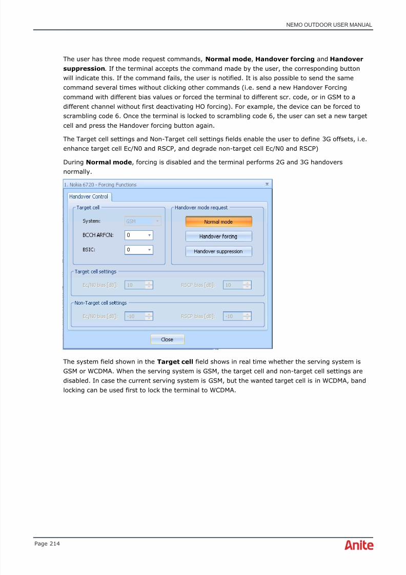
8/16/2019 Nemo Outdoor User Manual
http://slidepdf.com/reader/full/nemo-outdoor-user-manual 214/391
NEMO OUTDOOR USER MANUAL
Page 214
The user has three mode request commands, Normal mode , Handover forcing and Handoversuppression . If the terminal accepts the command made by the user, the corresponding buttonwill indicate this. If the command fails, the user is notified. It is also possible to send the samecommand several times without clicking other commands (i.e. send a new Handover Forcingcommand with different bias values or forced the terminal to different scr. code, or in GSM to adifferent channel without first deactivating HO forcing). For example, the device can be forced toscrambling code 6. Once the terminal is locked to scrambling code 6, the user can set a new targetcell and press the Handover forcing button again.
The Target cell settings and Non-Target cell settings fields enable the user to define 3G offsets, i.e.enhance target cell Ec/N0 and RSCP, and degrade non-target cell Ec/N0 and RSCP)
During Normal mode , forcing is disabled and the terminal performs 2G and 3G handoversnormally.
The system field shown in the Target cell field shows in real time whether the serving system isGSM or WCDMA. When the serving system is GSM, the target cell and non-target cell settings aredisabled. In case the current serving system is GSM, but the wanted target cell is in WCDMA, bandlocking can be used first to lock the terminal to WCDMA.

8/16/2019 Nemo Outdoor User Manual
http://slidepdf.com/reader/full/nemo-outdoor-user-manual 215/391
NEMO OUTDOOR USER MANUAL
Page 215
Once target cell settings including biasing information are defined by the user, handover mode canbe changed to Handover forcing mode by pressing the button. Handover forcing is done by biasingtarget and non-target cell Ec/N0 and RSCP values. Therefore it is also possible to bias the currentactive cell. For example, in the example below active set includes only one scrambling code. Bypressing the Handover forcing button, the terminal reports biasing Ec/N0 and RSCP values as setby the user. When the mode is changed back to Normal mode the terminal reports unbiasedvalues.
In the next example regarding Forced 3G handover and measurement report modification, theterminal active set includes scrambling code 63 with Ec/N0 value -7.6dB shown as a brown curve.
Scrambling code 6 and 255 are seen in the monitored set with colors blue and green. Scramblingcode 6 is selected to be a target cell.
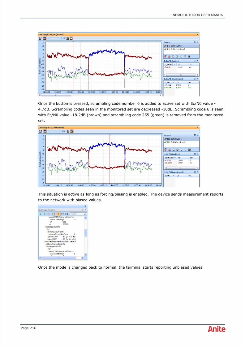
8/16/2019 Nemo Outdoor User Manual
http://slidepdf.com/reader/full/nemo-outdoor-user-manual 216/391
NEMO OUTDOOR USER MANUAL
Page 216
Once the button is pressed, scrambling code number 6 is added to active set with Ec/N0 value -4.7dB. Scrambling codes seen in the monitored set are decreased -10dB. Scrambling code 6 is seenwith Ec/N0 value -18.2dB (brown) and scrambling code 255 (green) is removed from the monitored
set.
This situation is active as long as forcing/biasing is enabled. The device sends measurement reportsto the network with biased values.
Once the mode is changed back to normal, the terminal starts reporting unbiased values.

8/16/2019 Nemo Outdoor User Manual
http://slidepdf.com/reader/full/nemo-outdoor-user-manual 217/391
NEMO OUTDOOR USER MANUAL
Page 217
When the Handover suppression button is pressed, the terminal is not allowed to do handoversto other cells. It should be noted that target cell biasing can be done only with WCDMA. Biasing/measurement report message modification is not possible with GSM at the moment. You can usethis feature, for example, to find the edge of a cell by stopping the handovers from taking placewhen driving away from a base station.
♦ Note that with scripts you can also perform handover forcing from one system to another.See chapter Making script files.

8/16/2019 Nemo Outdoor User Manual
http://slidepdf.com/reader/full/nemo-outdoor-user-manual 218/391
NEMO OUTDOOR USER MANUAL
Page 218

8/16/2019 Nemo Outdoor User Manual
http://slidepdf.com/reader/full/nemo-outdoor-user-manual 219/391
NEMO OUTDOOR USER MANUAL
Page 219
6.21.5 Cell barring
♦ This functionality is available for Nokia 2G, Motorola 3G, and HiSilicon-based LTEterminals.
During the measurement you can select if you wish to access only cells that are accessible to allend users (Accept), all cells; that is, also cells that are barred (Ignore), and only barred cells(Reverse).
The Cell Barring dialog is accessed by selecting the device and clicking the Measurementsettings button in the Devices view and choosing Cell Barring . You can also selectMeasurement | <device name> | Cell Barring .
6.21.6 Set terminal radio on/off (airplane mode)It is possible to set the terminal radio on and off by selecting the device and clicking theMeasurement settings button in the Devices view and selecting Set Terminal RadioOn/Off . You can also select Measurement | <device name> | Set Terminal Radio On/Off .
The Device Status view will display a red indicator when the terminal radio is off.

8/16/2019 Nemo Outdoor User Manual
http://slidepdf.com/reader/full/nemo-outdoor-user-manual 220/391
NEMO OUTDOOR USER MANUAL
Page 220
6.21.7 AMR codec forcing
♦ This feature is available with Qualcomm-based devices.
It is possible to force a device to use a certain AMR codec mode. For example, when a UE is forcedto the WCDMA AMR WB codec, it can freely use any WB AMR codec from 6.6 kbps to 23.85 kbps..
The codecs are enabled/disabled from the Measurement Properties – Measurement page.
6.22 Cell testing
The surrounding cells of a location can be tested through an automated list of test calls that arelocked to a cell at a time. The Cell Testing dialog is accessed by selecting the device and clickingthe Measurement settings button in the Devices view and choosing Cell Testing . You canalso select Measurement | <device name> | Cell Testing .
P h o n e n u m b e r defines the phone number that is called at the outset of the cell test. During thecall the neighbor list which defines the cells to be tested is updated. This is necessary since if thecell from which the cell testing is performed is a strong one, without this call the neighbour list mayremain empty.
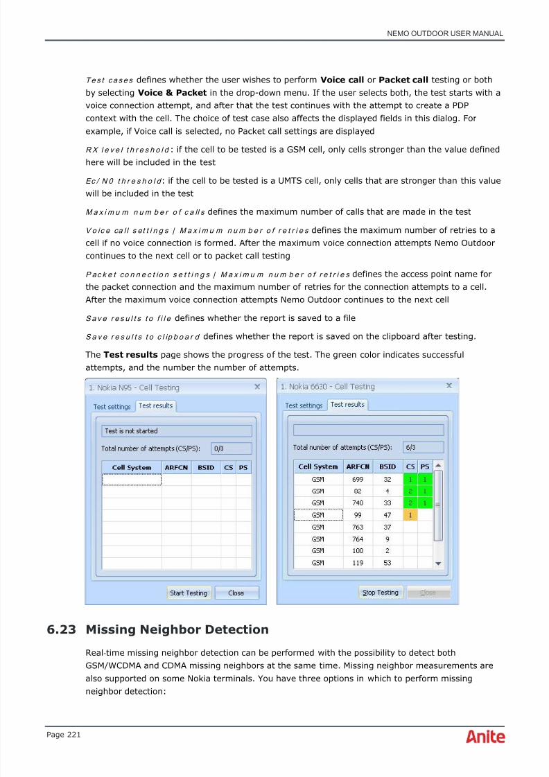
8/16/2019 Nemo Outdoor User Manual
http://slidepdf.com/reader/full/nemo-outdoor-user-manual 221/391
NEMO OUTDOOR USER MANUAL
Page 221
Te s t c a s e s defines whether the user wishes to perform Voice call or Packet call testing or bothby selecting Voice & Packet in the drop-down menu. If the user selects both, the test starts with avoice connection attempt, and after that the test continues with the attempt to create a PDPcontext with the cell. The choice of test case also affects the displayed fields in this dialog. Forexample, if Voice call is selected, no Packet call settings are displayed
R X l e v e l t h r e s h o l d : if the cell to be tested is a GSM cell, only cells stronger than the value definedhere will be included in the test
Ec / N 0 t h r e s h o l d : if the cell to be tested is a UMTS cell, only cells that are stronger than this valuewill be included in the test
M a x i m u m n u m b e r o f c a ll s defines the maximum number of calls that are made in the test
Vo ic e ca l l s et t i n g s | M a x i m u m n u m b e r o f r e t r i e s defines the maximum number of retries to acell if no voice connection is formed. After the maximum voice connection attempts Nemo Outdoorcontinues to the next cell or to packet call testing
P ac k e t co n n e c t io n s e t t i n g s | M a x i m u m n u m b e r o f r e t r i e s defines the access point name forthe packet connection and the maximum number of retries for the connection attempts to a cell.After the maximum voice connection attempts Nemo Outdoor continues to the next cell
S a v e r e s u l t s t o f i l e defines whether the report is saved to a file
S a v e r e s u l t s t o c l ip b o a r d defines whether the report is saved on the clipboard after testing.
The Test results page shows the progress of the test. The green color indicates successfulattempts, and the number the number of attempts.
6.23 Missing Neighbor Detection
Real -time missing neighbor detection can be performed with the possibility to detect bothGSM/WCDMA and CDMA missing neighbors at the same time. Missing neighbor measurements are
also supported on some Nokia terminals. You have three options in which to perform missingneighbor detection:

8/16/2019 Nemo Outdoor User Manual
http://slidepdf.com/reader/full/nemo-outdoor-user-manual 222/391
NEMO OUTDOOR USER MANUAL
Page 222
• with a mobile terminal supporting missing neighbor detection
• a scanner
• a scanner and a mobile
Each cell has list of neighboring intra-frequency, inter-frequency, and inter-system cells. A terminalsees/measures only cells in the neighbor list, whereas a scanner measures all available cells.Missing neighbor detection is based on comparing scanner measurements with the neighbor list ofthe mobile. Hence, a possible missing neighbor refers to a cell that is not in the neighbor list of themobile at a given time, but is detected/measured by the scanner. In mobile only missing neighbormeasurements, the mobile is able to detect also missing neighbors through the missing neighbordetection functionality.
6.23.1 Missing neighbor detection with a mobile
1. Connect your mobile phone to Nemo Outdoor.
2. In the Devices view, select the device and click the Measurement control button .Select Frequency Scanning Properties . Select BSIC decoding and Missing neighbordetection in the Frequency s canning view. Next, click on Select Channels .
♦ Note that both BSIC decoding and Missing neighbor detection need to be selected andTop-N option deselected.
3. Select the channels for scanning in the Select Channels dialog.
4. Click OK and OK .
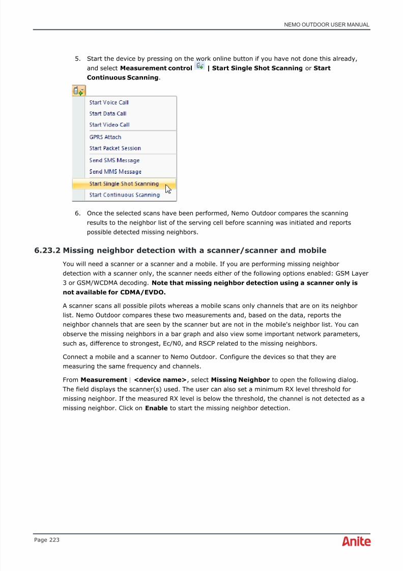
8/16/2019 Nemo Outdoor User Manual
http://slidepdf.com/reader/full/nemo-outdoor-user-manual 223/391
NEMO OUTDOOR USER MANUAL
Page 223
5. Start the device by pressing on the work online button if you have not done this already,and select Measurement control | Start Single Shot Scanning or StartContinuous Scanning .
6. Once the selected scans have been performed, Nemo Outdoor compares the scanningresults to the neighbor list of the serving cell before scanning was initiated and reportspossible detected missing neighbors.
6.23.2 Missing neighbor detection with a scanner/scanner and mobile
You will need a scanner or a scanner and a mobile. If you are performing missing neighbordetection with a scanner only, the scanner needs either of the following options enabled: GSM Layer3 or GSM/WCDMA decoding. Note that missing neighbor detection using a scanner only isnot available for CDMA/EVDO.
A scanner scans all possible pilots whereas a mobile scans only channels that are on its neighborlist. Nemo Outdoor compares these two measurements and, based on the data, reports theneighbor channels that are seen by the scanner but are not in the mobile's neighbor list. You canobserve the missing neighbors in a bar graph and also view some important network parameters,such as, difference to strongest, Ec/N0, and RSCP related to the missing neighbors.
Connect a mobile and a scanner to Nemo Outdoor. Configure the devices so that they aremeasuring the same frequency and channels.
From Measurement | <device name> , select Missing Neighbor to open the following dialog.The field displays the scanner(s) used. The user can also set a minimum RX level threshold for
missing neighbor. If the measured RX level is below the threshold, the channel is not detected as amissing neighbor. Click on Enable to start the missing neighbor detection.
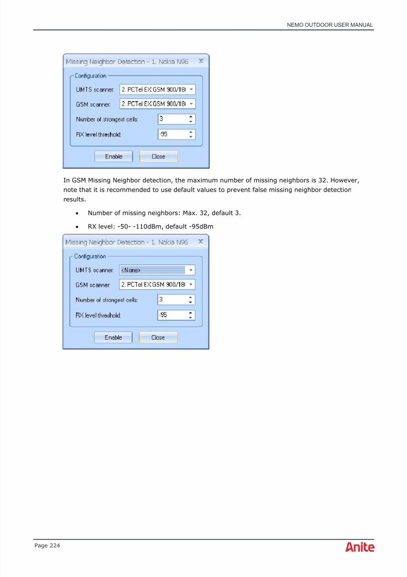
8/16/2019 Nemo Outdoor User Manual
http://slidepdf.com/reader/full/nemo-outdoor-user-manual 224/391
NEMO OUTDOOR USER MANUAL
Page 224
In GSM Missing Neighbor detection, the maximum number of missing neighbors is 32. However,note that it is recommended to use default values to prevent false missing neighbor detection
results.• Number of missing neighbors: Max. 32, default 3.
• RX level: -50- -110dBm, default -95dBm

8/16/2019 Nemo Outdoor User Manual
http://slidepdf.com/reader/full/nemo-outdoor-user-manual 225/391
NEMO OUTDOOR USER MANUAL
Page 225
Open a bar graph, for example, with a Missing Neighbor Ec/N0 layer ( Data | Bar Graph | New ,click the New Layer button and select the parameter in the Y box). The bar graph with theselected parameter will display the missing neighbor channel(s).
6.24 Pilot pollution analysis
Available for UMTS, CDMA and EVDO networks, Pilot Pollution Analysis measurements can beperformed in real time with Nemo Outdoor by using test terminals or a scanning receiver. In a pilotpollution situation there are more active/monitored pilots than a handset can measure, or there isno clear dominance for any pilots in the area. The pilot signal is used to distinguish cells in thenetwork from one another. Pilot pollution analysis is done based on CELL MEASUREMENT events,and analysis is always active. The user can define thresholds for pilot pollution analysis via NemoOutdoor’s UI. Pilot pollution is detected when all the criterias match.
Right-click on the device in the Devices view and select Pilot Pollution Analysis .
The user can define thresholds for pilot pollution analysis via Nemo Outdoor user interface.

8/16/2019 Nemo Outdoor User Manual
http://slidepdf.com/reader/full/nemo-outdoor-user-manual 226/391
NEMO OUTDOOR USER MANUAL
Page 226
Ec / N 0 a c t i v e se t b e s t b e lo w t h r e s h o l d ( d B ) (for UMTS): The default value is set to -12dB. Pilotpollution analysis is done when the best reported active set Ec/N0 value is below -12dB.
Ec / I 0 a c t iv e s et b e s t b e lo w t h r e s h o l d ( d B ) (for CDMA and EVDO): The default value is set to -12dB. Pilot pollution analysis is done when the best reported active set Ec/I0 value is below -12dB.
R SCP a c t i v e s e t b e s t a b o v e t h r e s h o l d ( d B ) (for UMTS): The default value is set to -95dBm.Pilot pollution analysis is done when the reported active set best RSCP value is above -95dBm.
R SCP ( E c ) a c t i v e s e t b e s t a b o v e t h r e s h o l d (for CDMA and EVDO): The default value is set to -95dBm. Pilot pollution analysis is done when reported active set best RSCP value is above -95dBm
P o ll u t e r l e v el w i n d o w f r o m b e s t a ct i v e se t c e ll ( d B ) (for UMTS): The default value is set to -6dB. Pilot pollution analysis is done when the Ec/N0 values of polluting pilots are within -6dB fromthe best active set Ec/N0 value.
P o l lu t e r l e v e l w i n d o w f r o m b e s t a c t iv e s e t ce l l (for CDMA and EVDO): The default value is setto -6dB. Pilot pollution analysis is done when Ec/I0 values of polluting pilots are within -6dB from
the best active set Ec/I0 value.
P i lo t c o u n t t h r e s h o l d (for UMTS): The default value is set to 3. The number of cells that arewithin the user-defined window from the Ec/N0 of active set best cell. The pilot count includesactive and monitored sets. For example, pilot pollution analysis is performed when more than threepilots are detected within the user-defined window from the Ec/N0 of active set best cell.
P il o t c o u n t t h r e s h o l d (for CDMA and EVDO): The default value is set to 3. The number of cellsthat are within the user-defined window from the Ec/I0 of active set best cell. Pilot count includesactive and neighbor sets. For example, pilot pollution analysis is performed when more than threepilots are detected within the user-defined window from the Ec/I0 of active set best cell.
Start recording by clicking on the Start recording button .
6.24.1 UMTS Pilot Pollution Analysis on Mobile Phone
Pilot pollution analysis results are written to a log file as an event of their own, called”CELLPOLLUTION”.
The event includes the following information:
• Source system
• Source band
• Source channel number
• Pilot pollution scrambling code
• Pilot pollution Ec/N0
• Pilot pollution RSCP
• Cell name of polluting pilot (if cell site file is used)
• Cell ID of polluting pilot (if cell site file is used)
♦ NOTE! Cell site file (BTS file) is not used with scanning receivers with Nemo Outdoor atthe moment.
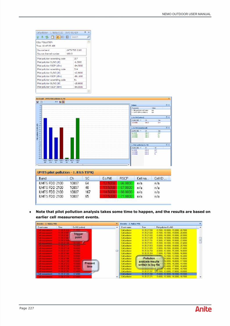
8/16/2019 Nemo Outdoor User Manual
http://slidepdf.com/reader/full/nemo-outdoor-user-manual 227/391
NEMO OUTDOOR USER MANUAL
Page 227
♦ Note that pilot pollution analysis takes some time to happen, and the results are based onearlier cell measurement events.

8/16/2019 Nemo Outdoor User Manual
http://slidepdf.com/reader/full/nemo-outdoor-user-manual 228/391
NEMO OUTDOOR USER MANUAL
Page 228
6.24.2 UMTS pilot pollution analysis based on scanner measurements
• Ec/N0 values for pilots are less than -12dB
• Ec/N0 values of the pilots are within -6dB from the best Ec/N0 value
6.24.3 CDMA/EVDO pilot pollution analysis - Mobile phones
Pilot pollution analysis results are written to a log file as an event of their own, called”CELLPOLLUTION”.
The event includes the following information:
• Source system
• Source band
• Source channel number
•
Pilot pollution scrambling code• Pilot pollution Ec/I0
• Pilot pollution RSCP
• Cell name of polluting pilot (if cell site file is used)
• Cell ID of polluting pilot (if cell site file is used)
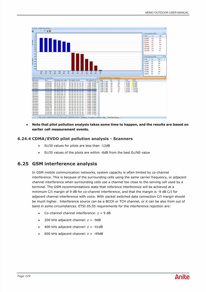
8/16/2019 Nemo Outdoor User Manual
http://slidepdf.com/reader/full/nemo-outdoor-user-manual 229/391
NEMO OUTDOOR USER MANUAL
Page 229
♦ Note that pilot pollution analysis takes some time to happen, and the results are based onearlier cell measurement events.
6.24.4 CDMA/EVDO pilot pollution analysis - Scanners
• Ec/I0 values for pilots are less than -12dB
• Ec/I0 values of the pilots are within -6dB from the best Ec/N0 value
6.25 GSM interference analysis
In GSM mobile communication networks, system capacity is often limited by co-channelinterference. This is because of the surrounding cells using the same carrier frequency, or adjacentchannel interference when surrounding cells use a channel too close to the serving cell used by aterminal. The GSM recommendations state that reference interference will be achieved at aminimum C/I margin of 9 dB for co-channel interference, and that the margin is -9 dB C/I foradjacent channel interference with voice. With packet switched data connection C/I margin shouldbe much higher. Interference source can be a BCCH or TCH channel, or it can be also from out ofband in some circumstances. ETSI 05.05 requirements for the interference rejection are:
• Co-channel channel interference: z = 9 dB
• 200 kHz adjacent channel: z = -9dB
• 400 kHz adjacent channel: z = -41dB
• 600 kHz adjacent channel: z = -49dB
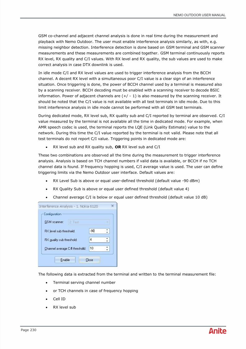
8/16/2019 Nemo Outdoor User Manual
http://slidepdf.com/reader/full/nemo-outdoor-user-manual 230/391
NEMO OUTDOOR USER MANUAL
Page 230
GSM co-channel and adjacent channel analysis is done in real time during the measurement andplayback with Nemo Outdoor. The user must enable interference analysis similarly, as with, e.g.missing neighbor detection. Interference detection is done based on GSM terminal and GSM scannermeasurements and these measurements are combined together. GSM terminal continuously reportsRX level, RX quality and C/I values. With RX level and RX quality, the sub values are used to makecorrect analysis in case DTX downlink is used.
In idle mode C/I and RX level values are used to trigger interference analysis from the BCCHchannel. A decent RX level with a simultaneous poor C/I value is a clear sign of an interferencesituation. Once triggering is done, the power of BCCH channel used by a terminal is measured alsoby a scanning receiver. BCCH decoding must be enabled with a scanning receiver to decode BSICinformation. Power of adjacent channels are (+/ - 1) is also measured by the scanning receiver. Itshould be noted that the C/I value is not available with all test terminals in idle mode. Due to thislimit interference analysis in idle mode cannot be performed with all GSM test terminals.
During dedicated mode, RX level sub, RX quality sub and C/I reported by terminal are observed. C/I
value measured by the terminal is not available all the time in dedicated mode. For example, whenAMR speech codec is used, the terminal reports the LQE (Link Quality Estimate) value to thenetwork. During this time the C/I value reported by the terminal is not valid. Please note that alltest terminals do not report C/I value. Triggering points in dedicated mode are:
• RX level sub and RX quality sub, OR RX level sub and C/I
These two combinations are observed all the time during the measurement to trigger interferenceanalysis. Analysis is based on TCH channel numbers if valid data is available, or BCCH if no TCHchannel data is found. If frequency hopping is used, C/I average value is used. The user can definetriggering limits via the Nemo Outdoor user interface. Default values are:
• RX Level Sub is above or equal user-defined threshold (default value -90 dBm)
• RX Quality Sub is above or equal user defined threshold (default value 4)
• Channel average C/I is below or equal user defined threshold (default value 10 dB)
The following data is extracted from the terminal and written to the terminal measurement file:
• Terminal serving channel number
• or TCH channels in case of frequency hopping
• Cell ID
• RX level sub

8/16/2019 Nemo Outdoor User Manual
http://slidepdf.com/reader/full/nemo-outdoor-user-manual 231/391
NEMO OUTDOOR USER MANUAL
Page 231
• RX quality sub
• C/I if available
For each terminal serving channel number X, the following data is extracted from scannermeasurements and written to terminal measurement file:
• Channel number, RX level and BSIC for channel X
• Channel number, RX level and BSIC for channel (X-1)
• Channel number, RX level and BSIC for channel (X+1)
Results are written to IANALYSIS event and can be displayed in different views, for example, in atable grid and bar graph. If BTS file is used also cell names for the serving and interfering cells canbe seen during the measurement and playback. Nemo Outdoor includes two predefined customwindows for GSM interference analysis. Table grid and bar graph.
6.26 Band scan
With the Nemo FSR1 scanner you can perform band scanning. All specified channels are scanned forthe selected band and technology and the strongest measured identifiers (CDMA PN, EVDO PN,WCDMA SC, LTE Cell ID) for every valid channel of that technology type are reported. Signal
strength and signal quality are reported for each identified channel. This feature is useful in areaswhere broadcasted technologies and bands are unknown.
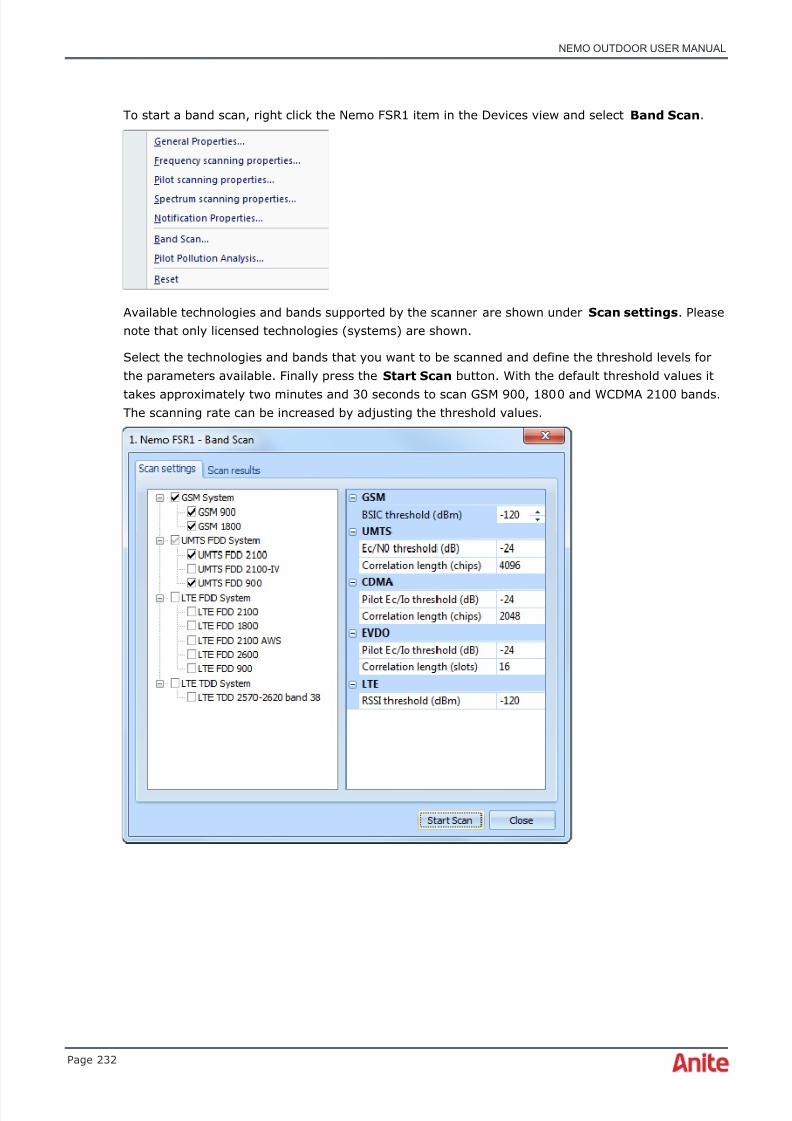
8/16/2019 Nemo Outdoor User Manual
http://slidepdf.com/reader/full/nemo-outdoor-user-manual 232/391
NEMO OUTDOOR USER MANUAL
Page 232
To start a band scan, right click the Nemo FSR1 item in the Devices view and select Band Scan .
Available technologies and bands supported by the scanner are shown under Scan settings . Pleasenote that only licensed technologies (systems) are shown.
Select the technologies and bands that you want to be scanned and define the threshold levels forthe parameters available. Finally press the Start Scan button. With the default threshold values it
takes approximately two minutes and 30 seconds to scan GSM 900, 1800 and WCDMA 2100 bands.The scanning rate can be increased by adjusting the threshold values.
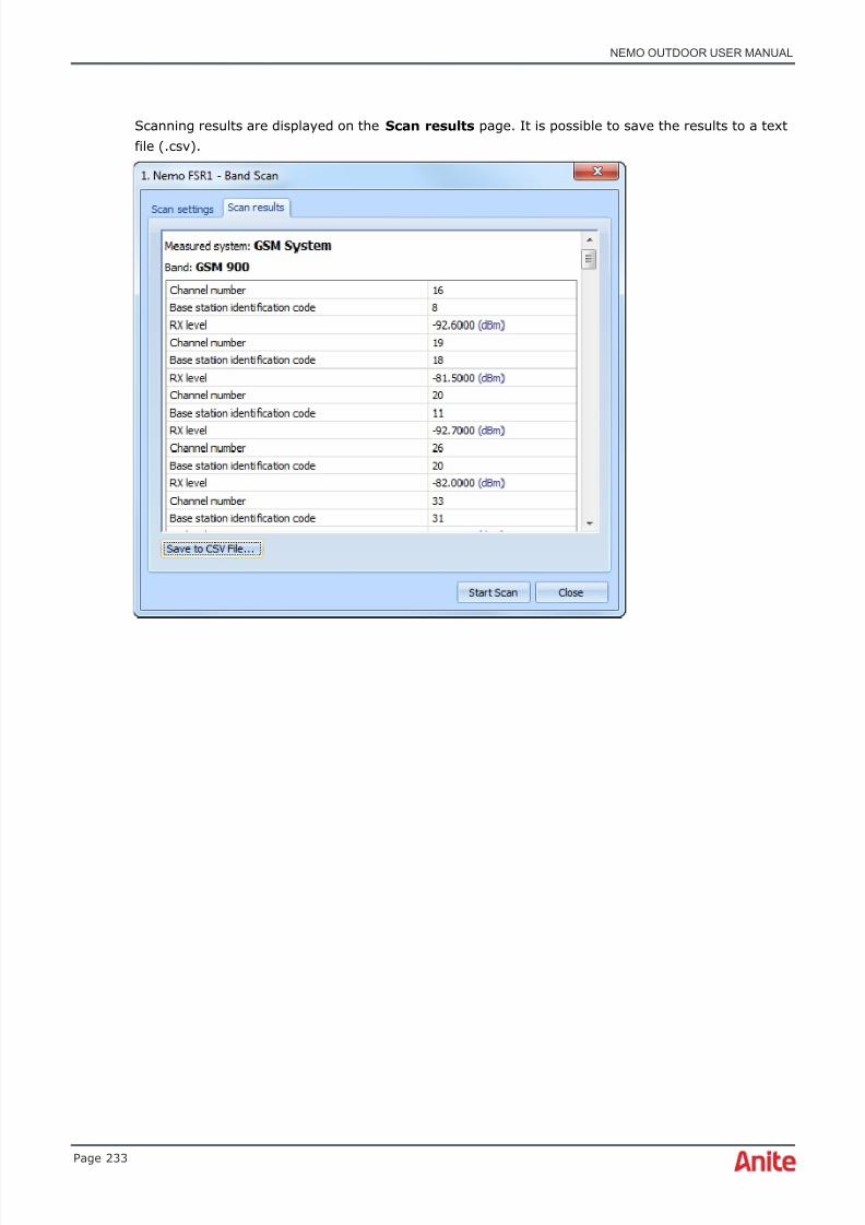
8/16/2019 Nemo Outdoor User Manual
http://slidepdf.com/reader/full/nemo-outdoor-user-manual 233/391
NEMO OUTDOOR USER MANUAL
Page 233
Scanning results are displayed on the Scan results page. It is possible to save the results to a textfile (.csv).
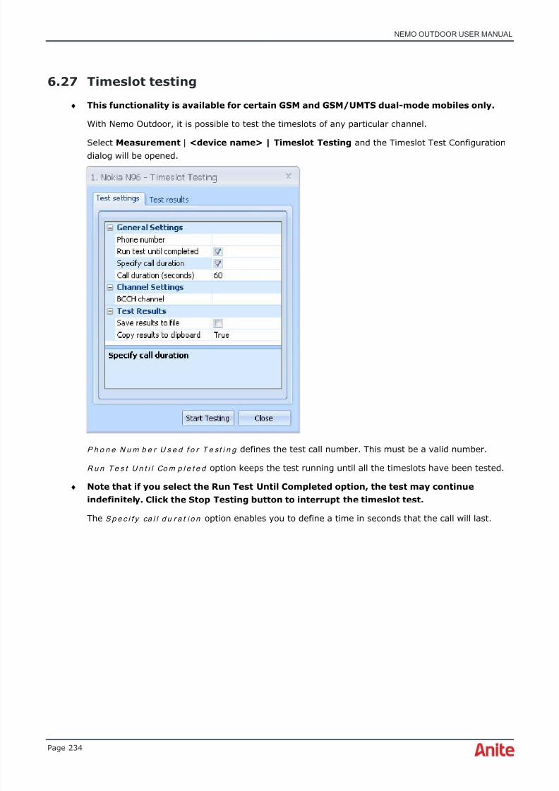
8/16/2019 Nemo Outdoor User Manual
http://slidepdf.com/reader/full/nemo-outdoor-user-manual 234/391
NEMO OUTDOOR USER MANUAL
Page 234
6.27 Timeslot testing
♦ This functionality is available for certain GSM and GSM/UMTS dual-mode mobiles only.
With Nemo Outdoor, it is possible to test the timeslots of any particular channel.
Select Measurement | <device name> | Timeslot Testing and the Timeslot Test Configurationdialog will be opened.
P h o n e N u m b e r U s e d f o r T e st i n g defines the test call number. This must be a valid number.
R u n Te s t U n t i l Co m p l e t e d option keeps the test running until all the timeslots have been tested.
♦ Note that if you select the Run Test Until Completed option, the test may continueindefinitely. Click the Stop Testing button to interrupt the timeslot test.
The S p e c i f y ca l l d u r a t i o n option enables you to define a time in seconds that the call will last.

8/16/2019 Nemo Outdoor User Manual
http://slidepdf.com/reader/full/nemo-outdoor-user-manual 235/391
NEMO OUTDOOR USER MANUAL
Page 235
In the Ch a n n e l Se t t i n g s | B CCH c h a n n e l you define the Channel (BCCH) that you want to test.Timeslots used by BCCH refers to the timeslots that are used for system messaging and thereforecannot be accessed with mobiles. Click on the … button to enter the Select Channel dialog.
S a v e r e s u l t s t o f i l e defines whether the report is saved to a file
S a v e r e s u l t s t o c l ip b o a r d defines whether the report is saved on the clipboard after testing.
On the Test results page you can view the progress of the test. Selecting timeslots will excludethem from the test, for example, in the case they are already reserved for data testing. Green colorindicates channels and their timeslots that have been called, and the number in the slot the numberof calls made in the timeslot. In the table you can see a list of all the TCHs of the selected channeland their timeslots. There is a yellow frame around the timeslot that was accessed during theprevious call. Those white timeslots that were not tested will turn red. This happens, for example, ifthe user stops the testing.
The N u m b e r o f Ca l l A t t e m p t s field tells how many calls have been made so far.
Click the Stop testing button to interrupt the timeslot test.
When there are no more white slots left, i.e. all time slots except for the ones that were excludedfrom the test by selecting them (grey), the measurement will stop on its own.

8/16/2019 Nemo Outdoor User Manual
http://slidepdf.com/reader/full/nemo-outdoor-user-manual 236/391
NEMO OUTDOOR USER MANUAL
Page 236
6.28 Viewing graphs
There are several types of graphs in Nemo Outdoor. There are some pre-made custom windows ofeach graph type that offer easy access to relevant network parameters. See chapter Customwindows for opening custom windows. To open an empty graph, select Data | [graph type] |New .
It is possible to view selected parameters in graphs by drag and dropping them in it. Click on aparameter in the Parameters view and drag and drop it on the graph. Move your mouse pointer ontop of a parameter in the Parameters view, and the tooltip will display more information about thatparticular parameter.
Parameters can also be opened for all devices at once and seen on different views. First, pressdown the Ctrl button and select the devices by clicking on them in the Parameter tree. After this,right-click on the wanted parameter from the parameter tree and select the graph type in whichyou want the parameter to be opened.
The options listed in the graph popup menu will be introduced next.

8/16/2019 Nemo Outdoor User Manual
http://slidepdf.com/reader/full/nemo-outdoor-user-manual 237/391
NEMO OUTDOOR USER MANUAL
Page 237
6.28.1 Graph popup menu
Right-click on the graph to open a popup menu with various tools for configuring the layout of thegraph.
6.28.1.1 Custom Window Properties dialog
In the Custom Window Properties dialog you can define the custom window name and selectgroups for the custom windows. The custom window groups define which custom windows areavailable for each device. For example, if you select LTE FDD, the custom window will only beavailable when an LTE device is added to Nemo Outdoor or you are playing back an LTEmeasurement.
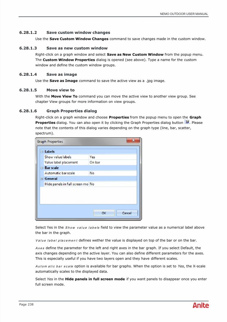
8/16/2019 Nemo Outdoor User Manual
http://slidepdf.com/reader/full/nemo-outdoor-user-manual 238/391
NEMO OUTDOOR USER MANUAL
Page 238
6.28.1.2 Save custom window changes
Use the Save Custom Window Changes command to save changes made in the custom window.
6.28.1.3 Save as new custom window
Right-click on a graph window and selectSave as New Custom Window
from the popup menu.The Custom Window Properties dialog is opened (see above). Type a name for the customwindow and define the custom window groups.
6.28.1.4 Save as image
Use the Save as Image command to save the active view as a .jpg image.
6.28.1.5 Move view to
With the Move View To command you can move the active view to another view group. Seechapter View groups for more information on view groups.
6.28.1.6 Graph Properties dialogRight-click on a graph window and choose Properties from the popup menu to open the GraphProperties dialog. You can also open it by clicking the Graph Properties dialog button . Pleasenote that the contents of this dialog varies depending on the graph type (line, bar, scatter,spectrum).
Select Yes in the S h o w v a l u e l a b e ls field to view the parameter value as a numerical label abovethe bar in the graph.
Va l u e l a b e l p la c e m e n t defines wether the value is displayed on top of the bar or on the bar.
A x e s define the parameter for the left and right axes in the bar graph. If you select Default, theaxis changes depending on the active layer. You can also define different parameters for the axes.This is especially useful if you have two layers open and they have different scales.
A u t o m a t i c b a r s c a le option is available for bar graphs. When the option is set to Yes , the X-scaleautomatically scales to the displayed data.
Select Yes in the Hide panels in full screen mode if you want panels to disappear once you enterfull screen mode.
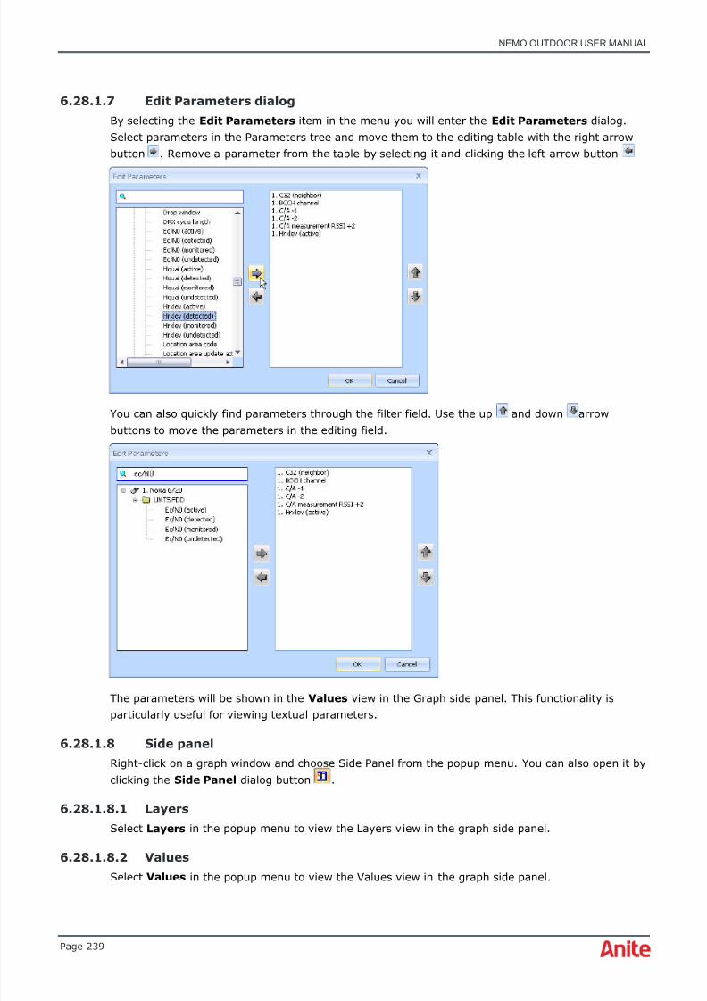
8/16/2019 Nemo Outdoor User Manual
http://slidepdf.com/reader/full/nemo-outdoor-user-manual 239/391
NEMO OUTDOOR USER MANUAL
Page 239
6.28.1.7 Edit Parameters dialog
By selecting the Edit Parameters item in the menu you will enter the Edit Parameters dialog.Select parameters in the Parameters tree and move them to the editing table with the right arrowbutton . Remove a parameter from the table by selecting it and clicking the left arrow button
You can also quickly find parameters through the filter field. Use the up and down arrowbuttons to move the parameters in the editing field.
The parameters will be shown in the Values view in the Graph side panel. This functionality isparticularly useful for viewing textual parameters.
6.28.1.8 Side panel
Right-click on a graph window and choose Side Panel from the popup menu. You can also open it byclicking the Side Panel dialog button .
6.28.1.8.1 Layers
Select Layers in the popup menu to view the Layers view in the graph side panel.
6.28.1.8.2 Values
Select Values in the popup menu to view the Values view in the graph side panel.

8/16/2019 Nemo Outdoor User Manual
http://slidepdf.com/reader/full/nemo-outdoor-user-manual 240/391
NEMO OUTDOOR USER MANUAL
Page 240
6.28.1.9 Full screen
Selecting the Full screen item in the popup menu will display Nemo Outdoor in full screen mode.
6.28.2 Zoom - Scatter graph
To zoom in on a scatter graph, drag your mouse diagonally from either corner with the green dottowards the corners with the red dots. To zoom out, do the same in reverse, dragging the mousefrom a red dot to a green dot.

8/16/2019 Nemo Outdoor User Manual
http://slidepdf.com/reader/full/nemo-outdoor-user-manual 241/391
NEMO OUTDOOR USER MANUAL
Page 241
6.28.3 Graph side panel - Layers
The layers can be dragged and dropped on some toolbar buttons. For example, a layer can bedragged and dropped on the Remove layer button to remove the layer. The order of the layerscan also be changed by dragging them with the mouse.
The layer is now removed.
To create space in the graph side panel, you can also click on the X button in the right-hand cornerof the Layers view. To reopen the view, right-click on the graph and select Layers in the popupmenu. You can also change the order of the parameters in the graph by dragging them in theLayers view.

8/16/2019 Nemo Outdoor User Manual
http://slidepdf.com/reader/full/nemo-outdoor-user-manual 242/391
NEMO OUTDOOR USER MANUAL
Page 242
Right-click on the Layers view to view the Layers popup menu.

8/16/2019 Nemo Outdoor User Manual
http://slidepdf.com/reader/full/nemo-outdoor-user-manual 243/391
NEMO OUTDOOR USER MANUAL
Page 243
6.28.3.1 Grouping layers
The N e w Gr o u p , R e n a m e G r o u p , R e m o v e G r o u p , M o v e G r o u p U p , M o v e Gr o u p D o w n andG r o u p S i m i l a r L a y e r s items are used in editing and organizing layer groups. Layer groups can beused to group parameters with the same unit and scale. Parameters in the same group will be
displayed in the same scales and the different groups will be stacked in the graph.
The Layers view displays all parameters added in the graph.

8/16/2019 Nemo Outdoor User Manual
http://slidepdf.com/reader/full/nemo-outdoor-user-manual 244/391
NEMO OUTDOOR USER MANUAL
Page 244
Righ-click on the view and select Group Similar Layers .
The parameters will be organized into groups based on the parameter unit.
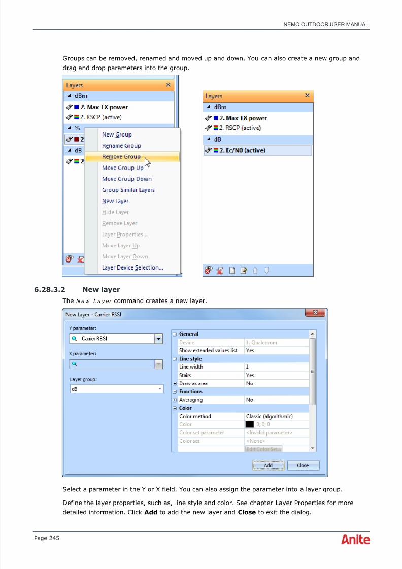
8/16/2019 Nemo Outdoor User Manual
http://slidepdf.com/reader/full/nemo-outdoor-user-manual 245/391
NEMO OUTDOOR USER MANUAL
Page 245
Groups can be removed, renamed and moved up and down. You can also create a new group anddrag and drop parameters into the group.
6.28.3.2 New layer
The N e w L a y er command creates a new layer.
Select a parameter in the Y or X field. You can also assign the parameter into a layer group.
Define the layer properties, such as, line style and color. See chapter Layer Properties for moredetailed information. Click Add to add the new layer and Close to exit the dialog.
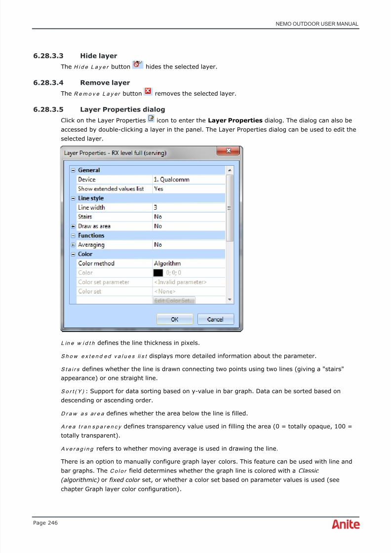
8/16/2019 Nemo Outdoor User Manual
http://slidepdf.com/reader/full/nemo-outdoor-user-manual 246/391
NEMO OUTDOOR USER MANUAL
Page 246
6.28.3.3 Hide layer
The H i d e L a y e r button hides the selected layer.
6.28.3.4 Remove layer
The R e m o v e L a y er button removes the selected layer.
6.28.3.5 Layer Properties dialog
Click on the Layer Properties icon to enter the Layer Properties dialog. The dialog can also beaccessed by double-clicking a layer in the panel. The Layer Properties dialog can be used to edit theselected layer.
L in e w i d t h defines the line thickness in pixels.
S h o w e x t e n d e d v a l u e s li s t displays more detailed information about the parameter.
S t a i r s defines whether the line is drawn connecting two points using two lines (giving a "stairs"appearance) or one straight line.
S o r t ( Y ) : Support for data sorting based on y-value in bar graph. Data can be sorted based ondescending or ascending order.
D r a w a s a r e a defines whether the area below the line is filled.
A r e a t r a n s p a r e n c y defines transparency value used in filling the area (0 = totally opaque, 100 =totally transparent).
Av e r a g i n g refers to whether moving average is used in drawing the line.
There is an option to manually configure graph layer colors. This feature can be used with line andbar graphs. The C o l o r field determines whether the graph line is colored with a Classic(algorithmic) or fixed color set, or whether a color set based on parameter values is used (seechapter Graph layer color configuration) .

8/16/2019 Nemo Outdoor User Manual
http://slidepdf.com/reader/full/nemo-outdoor-user-manual 247/391
NEMO OUTDOOR USER MANUAL
Page 247
W i n d o w s i ze defines the number of values to be averaged.
A u t o m a t i c sc a le the minimum and maximum values of the scale are defined automatically basedon the minimum and maximum values visible on the screen.
U s e v a l u e s c a l e d e f a u l t s : the minimum and maximum values of the scale can be defined by theuser, so the maximum and minimum values are not dependent on the values that are displayed.Note that if you want to select No in the drop-down menu, A u t o m a t i c sc a le also needs to be set toNo .
M i n i m u m defines the minimum value of the scale, if Automatic scale is set to No. If Automaticscale is set to Yes, this is not used
M a x i m u m defines the maximum value of the scale if Automatic scale is set to No . If Automaticscale is set to Yes , this is not used.
M i n i m u m a n d m a x i m u m t h r e s h o l d define the maximum and minimum values at which the user-defined limits for a measurement result is set. Horizontal lines help determine if the value goes
below or above the minimum and maximum values.
Depending on the parameter, it is possible to define various filters:
• C h a n n e l : list of channels whose measurement values are shown (Ch = ch1 or ch2 or ch 3or… AND Pilot 0 p1 or p2 or o3 or...). If the list is empty, no filtering is used
• P i l o t : list of channels and pilots whose measurement values are shown (Ch = ch1 or ch2 orch 3 or… AND Pilot 0 p1 or p2 or o3 or...). If the list is empty, appropriate filtering is notused so that it is possible to filter only channels, only pilots or both
• F r e q u e n c y : list of frequencies whose measurement values are shown (Freq = f1 or f2 or f3or…); if the list is empty, no filtering is used
• To p N : only N best measurement results are shown based on a defined parameter. If 0, nofiltering is used
• T o p N ( Y ) : Support for best TOP-N filtering based on y-value in line and bar graphs. E.g.,only the best two values can be seen in the line or bar graph
• B o t t o m N ( y ) : This can be done by selecting number of topN and select sorting order. E.g.,below bottom three RX levels are shown.
Some of the graph types support data tips. Hover the mouse cursor over the graph line or bar. Thedata tip will display information from that point of time.
Parameters with instantaneous values display points instead of a line in a graph. Such parametersare, for example, RACH TX Power , RACH Preamble Step and RACH Preamble Count . Such graphsinclude also the following layer properties.
P o i n t s t y l e allows you to select among various icons such as a triangle or a cross to display theinstantaneous values in the graph
P o i n t s i z e defines the size of the points in pixels in the graph
P o i n t t r a n s p a r e n c y defines the degree of point transparency.
6.28.3.6 Arrow down/up
The A r r o w D o w n and A r r ow U p icons will move the selected layer up or down in the graphpanel. You can also change the order of the parameters in the graph by dragging them in theLayers view with the mouse.
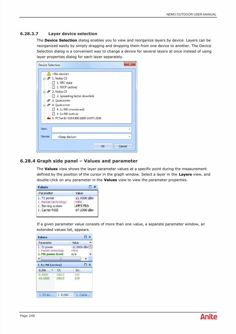
8/16/2019 Nemo Outdoor User Manual
http://slidepdf.com/reader/full/nemo-outdoor-user-manual 248/391
NEMO OUTDOOR USER MANUAL
Page 248
6.28.3.7 Layer device selection
The Device Selection dialog enables you to view and reorganize layers by device. Layers can bereorganized easily by simply dragging and dropping them from one device to another. The DeviceSelection dialog is a convenient way to change a device for several layers at once instead of using
layer properties dialog for each layer separately.
6.28.4 Graph side panel – Values and parameter
The Values view shows the layer parameter values at a specific point during the measurement
defined by the position of the cursor in the graph window. Select a layer in the Layers view, anddouble-click on any parameter in the Values view to view the parameter properties.
If a given parameter value consists of more than one value, a separate parameter window, anextended values list, appears.
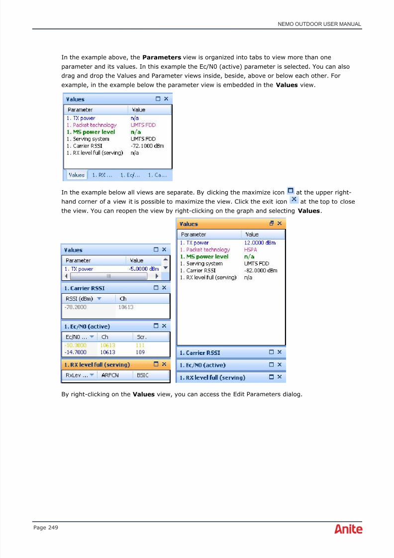
8/16/2019 Nemo Outdoor User Manual
http://slidepdf.com/reader/full/nemo-outdoor-user-manual 249/391
NEMO OUTDOOR USER MANUAL
Page 249
In the example above, the Parameters view is organized into tabs to view more than oneparameter and its values. In this example the Ec/N0 (active) parameter is selected. You can alsodrag and drop the Values and Parameter views inside, beside, above or below each other. Forexample, in the example below the parameter view is embedded in the Values view.
In the example below all views are separate. By clicking the maximize icon at the upper right-hand corner of a view it is possible to maximize the view. Click the exit icon at the top to closethe view. You can reopen the view by right-clicking on the graph and selecting Values .
By right-clicking on the Values view, you can access the Edit Parameters dialog.

8/16/2019 Nemo Outdoor User Manual
http://slidepdf.com/reader/full/nemo-outdoor-user-manual 250/391
NEMO OUTDOOR USER MANUAL
Page 250
6.28.5 Graph layer color configurationNemo Outdoor offers an option to manually configure graph layer colors. This feature can be usedwith line and bar graphs, and is very useful when observing a certain parameter or parameters, asdifferent colors can be assigned e.g., to different channels, scrambling codes, cell ID, etc. First, addparameters to the graph by dragging them from the parameter tree. Next, double-click on a layer inthe Layers side panel to enter the Layer Properties dialog.
If you select the Classic (algorithmic) option for coloring the graph, Nemo Outdoor will pick up thecolor automatically.

8/16/2019 Nemo Outdoor User Manual
http://slidepdf.com/reader/full/nemo-outdoor-user-manual 251/391
NEMO OUTDOOR USER MANUAL
Page 251
If you choose Fixed color , click … to enter the Colors dialog. Define the fixed color by selecting it inthe Standard or Custom page, or define the RGB for the color. Click OK . The graph will be coloredbased on the fixed color you selected.

8/16/2019 Nemo Outdoor User Manual
http://slidepdf.com/reader/full/nemo-outdoor-user-manual 252/391
NEMO OUTDOOR USER MANUAL
Page 252
Selecting Color set in the Color method drop-down menu will activate the Color set parameter and Color set fields.
Select a parameter in the Color set parameter drop-down menu, and a color set in the Color set drop-down menu. Note that only layer-specific parameters will be available in the Color setparameter menu.
To edit the color set in question, click on Edit Color Set.. button. It will lead you to the Color SetProperties dialog. Here you can edit the color set selected. See chapter Color Set Editor for moreinformation.
The parameter will be colored based on its values in the graph.
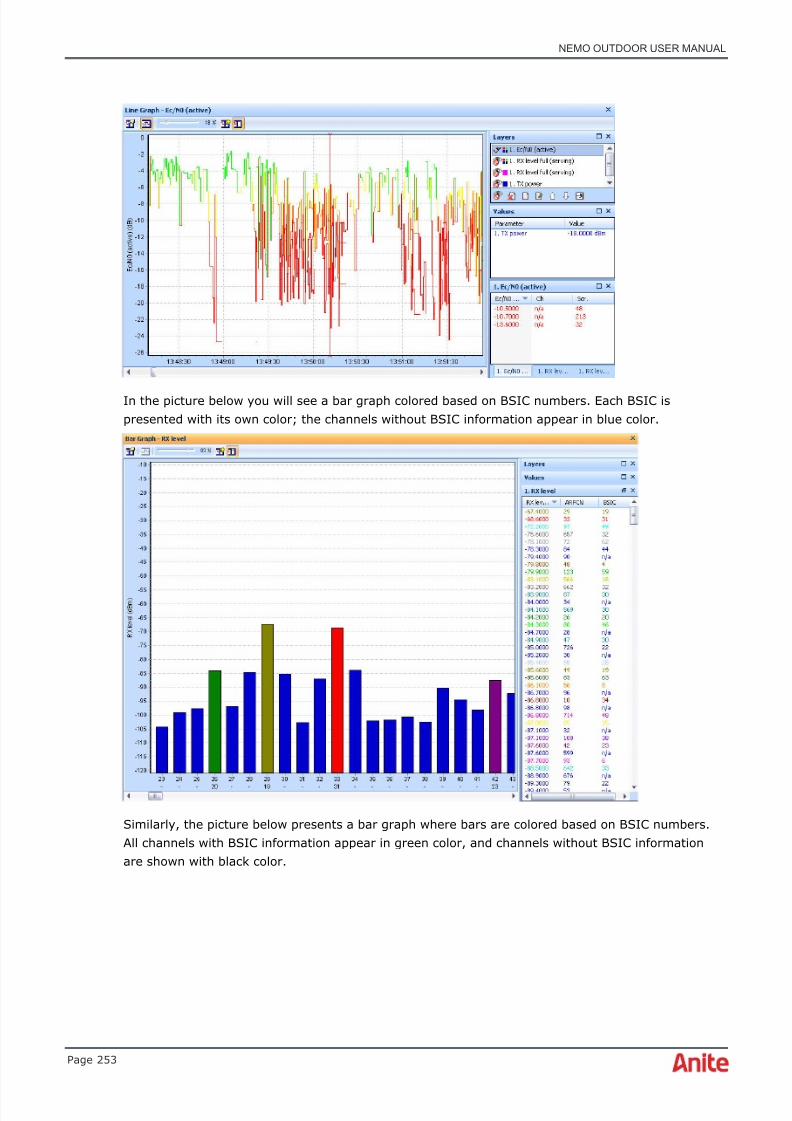
8/16/2019 Nemo Outdoor User Manual
http://slidepdf.com/reader/full/nemo-outdoor-user-manual 253/391
NEMO OUTDOOR USER MANUAL
Page 253
In the picture below you will see a bar graph colored based on BSIC numbers. Each BSIC ispresented with its own color; the channels without BSIC information appear in blue color.
Similarly, the picture below presents a bar graph where bars are colored based on BSIC numbers.All channels with BSIC information appear in green color, and channels without BSIC informationare shown with black color.
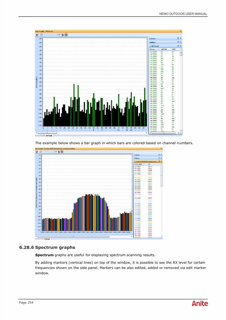
8/16/2019 Nemo Outdoor User Manual
http://slidepdf.com/reader/full/nemo-outdoor-user-manual 254/391
NEMO OUTDOOR USER MANUAL
Page 254
The example below shows a bar graph in which bars are colored based on channel numbers.
6.28.6 Spectrum graphs
Spectrum graphs are useful for displaying spectrum scanning results.
By adding markers (vertical lines) on top of the window, it is possible to see the RX level for certainfrequencies shown on the side panel. Markers can be also edited, added or removed via edit markerwindow.

8/16/2019 Nemo Outdoor User Manual
http://slidepdf.com/reader/full/nemo-outdoor-user-manual 255/391
NEMO OUTDOOR USER MANUAL
Page 255
With the peak value indicator tool you can visualize the peak value of the selected parameter foreach frequency. Open the Layer Properties dialog and select Yes in the Draw peak line field.
The peak value line will be drawn with the selected color. In the image below, the peak line isdrawn in red. To reset the peak line, right-click on the graph and select Reset Peak Lines .
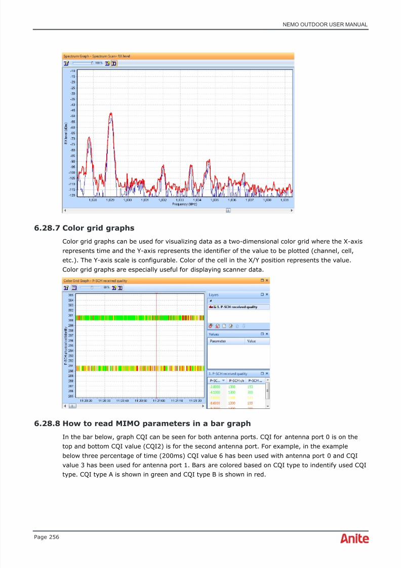
8/16/2019 Nemo Outdoor User Manual
http://slidepdf.com/reader/full/nemo-outdoor-user-manual 256/391

8/16/2019 Nemo Outdoor User Manual
http://slidepdf.com/reader/full/nemo-outdoor-user-manual 257/391
NEMO OUTDOOR USER MANUAL
Page 257
If more detailed information about the link adaptation is needed, it can be seen from the HSDPAlink adaptation information table grid. Distribution is shown for both antenna ports from the lastsample duration which is set to 200ms. E.g., four percentage of the time during the sampleduration modulation for antenna port 0 has been 16QAM with transport block size 14411 bits andfor the second antenna port 1 modulation was 16QAM with transport block size 12266 bits.
6.29 Viewing grids
Along with the graph windows, the grid tables offer you useful information about measurementevents, such as statistics from the current measurement, QoS parameters, Layer2 and Layer 3messages (the selection depends on the technology measured), and packet capture data. All eventscan be decoded by double-clicking on the event row. The decoded message is displayed in aseparate window. Alternatively, you can right-click on an event row and from the popup menuselect Decode Message. To open several decoded message windows, select Decode Message inNew Window option.
To view data in Packet decoder grids during playback, you need to enable the packet decodingfunction in Device Settings Measurement Properties | General | Advanced prior toperforming data measurements. Select Full or Partial in the Enable IP Capture field. A separate.pcap-file will be generated for the measurement, and this file needs to accompany themeasurement file in the same folder when viewing and decoding packet capture information inPacket Decoder grids in Nemo Outdoor. This requires Microsoft Network Monitor to be installed.
Please see chapter IP packet capturing for more information.
An empty grid table is opened by selecting Data | [Grid Type] | New . If you select one of theready-made custom windows and you have multiple devices connected to Nemo Outdoor, you needto select which device(s) you would like to view in the grid from the Select Device(s) to View dialog. In most grids you only view one device in a grid at a time. Open several grid windows toview multiple devices at the same time. However, in the Parameters grids you can view severaldevices simultaneously as separate columns.
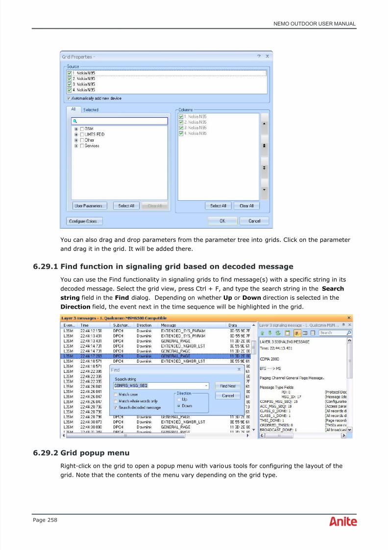
8/16/2019 Nemo Outdoor User Manual
http://slidepdf.com/reader/full/nemo-outdoor-user-manual 258/391
NEMO OUTDOOR USER MANUAL
Page 258
You can also drag and drop parameters from the parameter tree into grids. Click on the parameterand drag it in the grid. It will be added there.
6.29.1 Find function in signaling grid based on decoded message
You can use the Find functionality in signaling grids to find message(s) with a specific string in its
decoded message. Select the grid view, press Ctrl + F, and type the search string in the Searchstring field in the Find dialog. Depending on whether Up or Down direction is selected in theDirection field, the event next in the time sequence will be highlighted in the grid.
6.29.2 Grid popup menu
Right-click on the grid to open a popup menu with various tools for configuring the layout of thegrid. Note that the contents of the menu vary depending on the grid type.

8/16/2019 Nemo Outdoor User Manual
http://slidepdf.com/reader/full/nemo-outdoor-user-manual 259/391
NEMO OUTDOOR USER MANUAL
Page 259
6.29.2.1 Custom Window Properties dialog

8/16/2019 Nemo Outdoor User Manual
http://slidepdf.com/reader/full/nemo-outdoor-user-manual 260/391
NEMO OUTDOOR USER MANUAL
Page 260
In the Custom Window Properties dialog you can define the custom window name and selectgroups for the custom windows. The custom window groups define which custom windows areavailable for each device. For example, if you select LTE FDD, the custom window will only beavailable when an LTE device is added to Nemo Outdoor or you are playing back an LTEmeasurement.
6.29.2.2 Save custom window changes
Use the Save Custom Window Changes command to save changes made in the custom window.
6.29.2.3 Save as new custom window
With Save As New Custom Window you can save a new custom window. Selecting this item willopen the Custom Window Properties dialog.
6.29.2.4 Move view to
With the Move View To command you can move the active view to another view group. See
chapter View groups for more information on view groups.
6.29.2.5 Automatic scrolling
Select the Automatic Scrolling option in order to make the grid view scroll as the measurementprogresses.
6.29.2.6 Add/remove separator
In Parameters grids you can add empty lines (separators) to make the view easier to read. SelectRemove Separator to delete an empty line from the grid.
6.29.2.7 Open
Open allows you to open the selected parameter or statistic in another view (line graph, table grid,map, etc.). This item is available only with parameters and statistics grids.
6.29.2.8 Grid color configuration in events grids
To make grids more clear, you can colorize certain events in a grid based on the event name orevent ID. Right-click on a grid, and select Configure Colors from the popup menu, or click on theConfigure Colors button in the Grid Properties dialog. The Grid Color Configuration dialog isopened.
♦ Note that not all events and parameters are available with all devices.
In the events Grid Color Configuration dialog select the Event name column. You can set a text
color and/or a background color for the selected events. If you want to colorize the background,select Call events (Event name) in the Background Color Set field and select (none) in the TextColor Set field. Alternatively, if you want to colorize only the text in the grid, select Call Events (Event name) in the Text Color Set field from the drop-down menu and select (none) in theBackground Color Set field, as in the example below. Note that the contents of the Grid ColorConfiguration dialog depend on which columns have been selected in the Grid Properties dialog.

8/16/2019 Nemo Outdoor User Manual
http://slidepdf.com/reader/full/nemo-outdoor-user-manual 261/391
NEMO OUTDOOR USER MANUAL
Page 261
Click Edit to view the Color Set Properties dialog. Make sure that the color set type is string.Here you can also add more strings to the color set through Add…
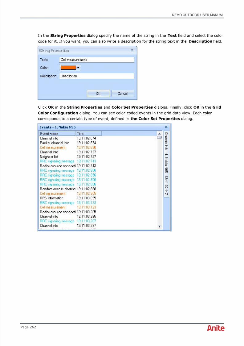
8/16/2019 Nemo Outdoor User Manual
http://slidepdf.com/reader/full/nemo-outdoor-user-manual 262/391
NEMO OUTDOOR USER MANUAL
Page 262
In the String Properties dialog specify the name of the string in the Text field and select the colorcode for it. If you want, you can also write a description for the string text in the Description field.
Click OK in the String Properties and Color Set Properties dialogs. Finally, click OK in the GridColor Configuration dialog. You can see color-coded events in the grid data view. Each colorcorresponds to a certain type of event, defined in the Color Set Properties dialog.

8/16/2019 Nemo Outdoor User Manual
http://slidepdf.com/reader/full/nemo-outdoor-user-manual 263/391
NEMO OUTDOOR USER MANUAL
Page 263
6.29.2.9 Grid color configuration based on decoded message in grids
Messages and Events grids can be color-coded based on a string in a message’s decoded message.In this case, you need to create a new color set in the Color Set Editor. It is possible to color-codeboth the text in the grid and the background color. While you can choose to colorize only one of
them, it is also possible to color-code both text and background. For example, you can have amessage appear in white text and blue background color. However, in that case remember to createtwo new color sets for the same string, for example, Decoded Text_1 and Decoded Text_2 . Belowyou will see an example of how to create a color set and set it for the background color. ClickAdd…

8/16/2019 Nemo Outdoor User Manual
http://slidepdf.com/reader/full/nemo-outdoor-user-manual 264/391
NEMO OUTDOOR USER MANUAL
Page 264
In the Color Set Properties dialog type, for example, Decoded Text in the Name field. You canalso create a short name for the new color set, or write a description for it. Select string as the colorset type. Click Add… In the String Properties dialog type in the string which will determine themessages to be colored with the new color set.

8/16/2019 Nemo Outdoor User Manual
http://slidepdf.com/reader/full/nemo-outdoor-user-manual 265/391
NEMO OUTDOOR USER MANUAL
Page 265
Click OK , and Close in the Color Set Editor .
Right-click on the grid and select Configure Colors . You can colorize the text color in the gridand/or the background color. If you want to colorize only the text, select the new color set createdabove, Decoded Text, in the Text Color Set field and select (none) in the Background Color Set field. In this example the background will be color-coded, so (none) is selected in the Text ColorSet field, and Decoded Text in the Background Color Set field. Click OK .

8/16/2019 Nemo Outdoor User Manual
http://slidepdf.com/reader/full/nemo-outdoor-user-manual 266/391
NEMO OUTDOOR USER MANUAL
Page 266
All messages with sysInfoType2 in its decoded message will be color-coded with the Decoded text color set.
6.29.2.10 Grid color configuration in events grids based on message name
Messages in Events grids can also be color-coded based on the message name. You can color-codethe message text or the background color, or both. Color-coding a message based on its name isdone in the same way as color-coding a message based on a specific string in its decoded message.However, when creating the new color set in the Color Set Editor | Color Set Properties | StringProperties , you need to type the name of the message you want to color-code instead of the stringin the decoded message. Below you will see an example of two color sets made for the samemessage name. Further, both the message text and background will be colorized. Click OK .
Also click OK in the Color Set Properties and Color Set Editor dialogs.
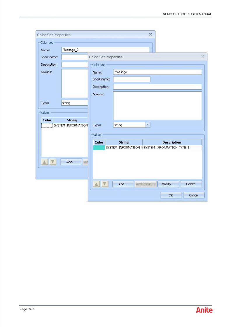
8/16/2019 Nemo Outdoor User Manual
http://slidepdf.com/reader/full/nemo-outdoor-user-manual 267/391
NEMO OUTDOOR USER MANUAL
Page 267

8/16/2019 Nemo Outdoor User Manual
http://slidepdf.com/reader/full/nemo-outdoor-user-manual 268/391
NEMO OUTDOOR USER MANUAL
Page 268
Next, right-click on the messages grid and select Configure Colors , or select Configure Colors inthe Grid Properties dialog. Select Message_2 in the Text Color Set field and Message in theBackground Color Set field. Click OK .
All messages called SYSTEM_INFORMATION_BCH will be color-coded with the new color sets.

8/16/2019 Nemo Outdoor User Manual
http://slidepdf.com/reader/full/nemo-outdoor-user-manual 269/391
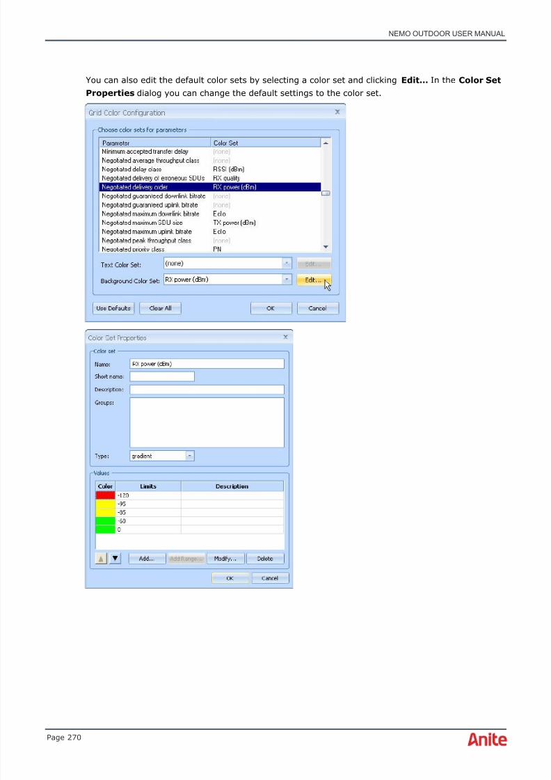
8/16/2019 Nemo Outdoor User Manual
http://slidepdf.com/reader/full/nemo-outdoor-user-manual 270/391
NEMO OUTDOOR USER MANUAL
Page 270
You can also edit the default color sets by selecting a color set and clicking Edit… In the Color SetProperties dialog you can change the default settings to the color set.

8/16/2019 Nemo Outdoor User Manual
http://slidepdf.com/reader/full/nemo-outdoor-user-manual 271/391
NEMO OUTDOOR USER MANUAL
Page 271
Parameters with assigned color sets are colorized according to their value. In the example below abackground of the parameter values has been color-coded. Click OK twice to exit the Grid ColorConfiguration dialog.
6.29.2.12 Grid color configuration for table grids
Table grids have default color sets assigned to them. Go to Data | Table Grid | New. In the GridProperties dialog select a device and a parameter set to be viewed in the table grid. Click OK .

8/16/2019 Nemo Outdoor User Manual
http://slidepdf.com/reader/full/nemo-outdoor-user-manual 272/391
NEMO OUTDOOR USER MANUAL
Page 272
The parameters are colorized according to their default color sets. You can also edit the defaultcolor sets. Right-click on the grid, select Configure Colors… the parameter you wish to edit, andEdit… The Color Set Properties dialog appears where you can change the color set settings. ClickOK to exit the dialogs and go back to the table grid.
You can also view cell name information for missing neighbors when a scanner and a mobile areused simultaneously.
6.29.2.13 Configure filters/quick filters
Another method to organize Events grids is to use filters. By using filters, only the selectedmessages will be displayed. Right-click on a grid view and select Configure Filters from the popupmenu
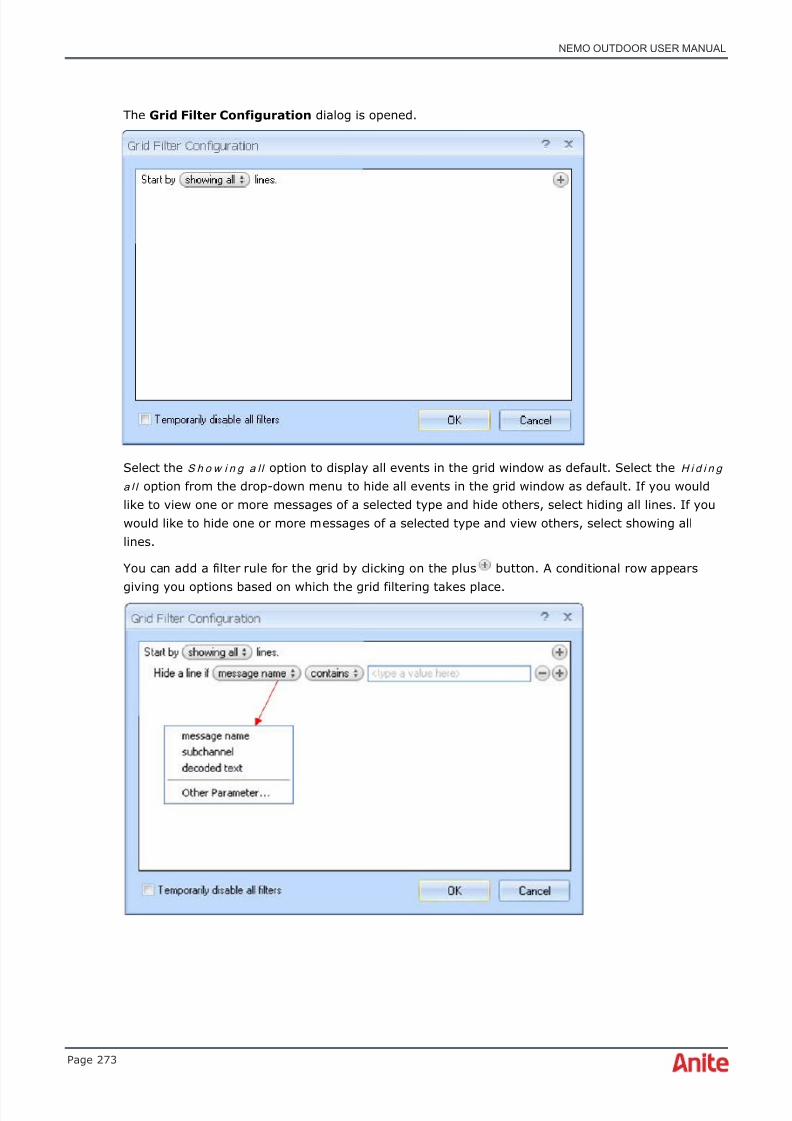
8/16/2019 Nemo Outdoor User Manual
http://slidepdf.com/reader/full/nemo-outdoor-user-manual 273/391
NEMO OUTDOOR USER MANUAL
Page 273
The Grid Filter Configuration dialog is opened.
Select the S h o w i n g a l l option to display all events in the grid window as default. Select the H i d i n g
a l l option from the drop-down menu to hide all events in the grid window as default. If you wouldlike to view one or more messages of a selected type and hide others, select hiding all lines. If youwould like to hide one or more messages of a selected type and view others, select showing alllines.
You can add a filter rule for the grid by clicking on the plus button. A conditional row appears
giving you options based on which the grid filtering takes place.

8/16/2019 Nemo Outdoor User Manual
http://slidepdf.com/reader/full/nemo-outdoor-user-manual 274/391
NEMO OUTDOOR USER MANUAL
Page 274
It is possible to set filtering rules for m e s sa g e n a m e , s u b c h a n n e l and d e c o d e d t e x t . In addition,you can select a parameter in the Select Parameter dialog which you can access through theOther Parameter… item in the filter target popup menu.
The contents of the condition menu vary depending on which item in the filter target menu isselected.
Note also that a separate, independent condition needs to be added from the plus icon at the topleft-hand corner of the dialog. If a condition has two or more constituents, the plus icon next tothe first constituent needs to be clicked. In this case the conditions are indented and combined with
one another with the text and if , and both conditions need to be met for the filtering to take place.

8/16/2019 Nemo Outdoor User Manual
http://slidepdf.com/reader/full/nemo-outdoor-user-manual 275/391
NEMO OUTDOOR USER MANUAL
Page 275
In the example above, a line is filtered out if a message contains a missing neighbor ec/n0 valuethat is less than -5 . The second filtering rule states that if a message name contains the textSYSTEM_INFORMATION_BCH and if a message contains SysInfoType18 , the message is filtered outfrom the grid.
The minus icon removes a row next to it from the list. Alternatively, you can delete all filters byright-clicking on a grid and selecting Quick Filter and Remove All Filters from the popup menu.
The Quick Filter menu offers a shortcut to defining filter rules for messages. Right-click on a row inthe grid and select Quick Filter from the popup menu.
You can now quickly define a filter for the selected layer message. You can choose to hide therespective message and all similar messages either according to the Event ( Hide this Event ),subchannel ( Hide This Subchannel ) or according to the message text ( Hide This Message ). Allmessages with the selected event, subchannel name or message text will be hidden. In the sameway, you can choose to display messages of the selected type only. Select Remove All Filters todelete all filter rules.
When filtering is enabled, the text Filtering will appear in the title bar.
6.29.2.14 Create notification
Select the Create Notification item to create a new notification matching the selected event. Formore information, see chapter Notification Configuration.
6.29.2.15 Decode message
This function will open the selected event row in a decoded form. You can also decode messages bydouble-clicking on the message row.
In the message decoding grid you can use the Show Next Message and Show PreviousMessage grid toolbar buttons to move to the previous/next message. If you move forward orback in the message decoding grid, use the Go to Message button to move to the samemessage in the messages grid. Click the Copy to Clipboard button to copy the contents of themessage decoding grid as text to clipboard.

8/16/2019 Nemo Outdoor User Manual
http://slidepdf.com/reader/full/nemo-outdoor-user-manual 276/391
NEMO OUTDOOR USER MANUAL
Page 276
With certain events such as cell measurement (CELLMEAS), it is also possible to arrange thecontents of the decoded message in three different ways.
The Format as list arranges the contents of a grid’s measurement results in a list. The Formatas horizontal table arranges the contents in the form of a horizontal table with columns, and
the Format as vertical table arranges the contents in a vertical table. The search field in thedecoded text window enables the user to find a string in the decoded message window.
Select a string of text in the decoded text, right-click on it and select Copy to copy the selected textas text to the clipboard. If no text is selected in the decoded text window, all text in it will becopied. This is the same as the Copy to Clipboard functionality.

8/16/2019 Nemo Outdoor User Manual
http://slidepdf.com/reader/full/nemo-outdoor-user-manual 277/391
NEMO OUTDOOR USER MANUAL
Page 277
6.29.2.16 Decode message in new window
This function enables you to have several decoded message windows open at the same time.
6.29.2.17 Automatic decode
The Automatic Decode function opens up a window which displays the currently selected or latestmessage in decoded form.
6.29.2.18 Save - Grid
The Save command allows you to save a selected event row as a text file (.txt). If you select theDecoded Text option, the decoded event text is saved in a text file. You can also save the entiregrid window as an image file (.jpg). From Events grids, you can export data into a MapInfo Tab-Fileor into a CSV file.
6.29.2.19 MapInfo Tab-file export
You can export measurement data into a MapInfo .tab file. In an Events grid, select Save |MapInfo Tab-File . See chapter MapInfo Tab-file export for more information.
6.29.2.20 CSV file export
You can export measurement data into a CSV file. In an Events grid, select Save | CSV File.
The exporting is supported for a single file, and the column separator can be a comma, semicolon,tab or space. The file(s) can be opened with third-party applications. Indoor files are not supportedat the moment. The user can select all events or only specific events from the grid for export.
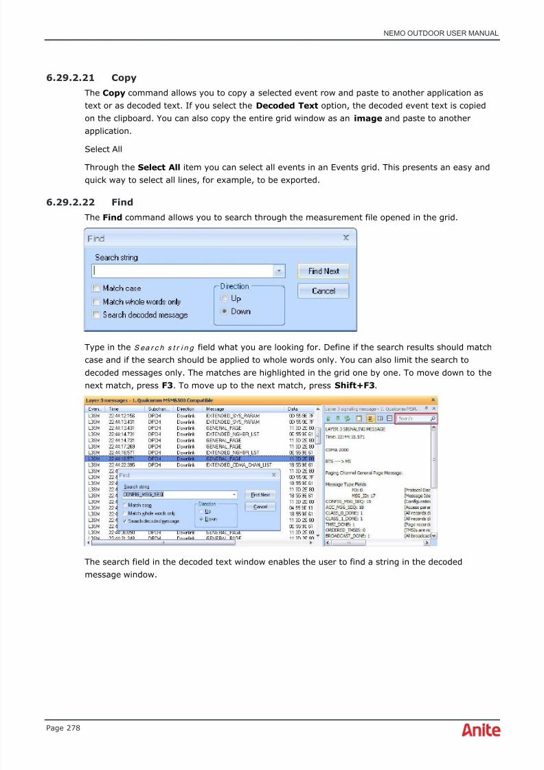
8/16/2019 Nemo Outdoor User Manual
http://slidepdf.com/reader/full/nemo-outdoor-user-manual 278/391
NEMO OUTDOOR USER MANUAL
Page 278
6.29.2.21 Copy
The Copy command allows you to copy a selected event row and paste to another application astext or as decoded text. If you select the Decoded Text option, the decoded event text is copiedon the clipboard. You can also copy the entire grid window as an image and paste to another
application.Select All
Through the Select All item you can select all events in an Events grid. This presents an easy andquick way to select all lines, for example, to be exported.
6.29.2.22 Find
The Find command allows you to search through the measurement file opened in the grid.
Type in the S ea r c h s t r i n g field what you are looking for. Define if the search results should matchcase and if the search should be applied to whole words only. You can also limit the search todecoded messages only. The matches are highlighted in the grid one by one. To move down to thenext match, press F3 . To move up to the next match, press Shift+F3 .
The search field in the decoded text window enables the user to find a string in the decodedmessage window.

8/16/2019 Nemo Outdoor User Manual
http://slidepdf.com/reader/full/nemo-outdoor-user-manual 279/391
NEMO OUTDOOR USER MANUAL
Page 279
Below you will see a list of commands for the decoded text view.
Ctrl + Shift + F = Go to search field in decoded text view
Enter = Highlight next match in decoded text view (when search field is focused)
Shift + Enter = Highlight previous match in decoded text view (when search field is focused)
Esc = Clear search field in decoded text view (when search field is focused)
Full Screen
The Full Screen item enables you to view Nemo Outdoor in full screen mode.
6.29.2.23 Grid Properties dialog
Right-click on a grid table and select Properties from the popup menu. The Grid Properties dialogis opened.
♦ Note that the appearance of the grid and the selection of parameters depend on the gridtype and on the measurement device.

8/16/2019 Nemo Outdoor User Manual
http://slidepdf.com/reader/full/nemo-outdoor-user-manual 280/391
NEMO OUTDOOR USER MANUAL
Page 280
You can select events, parameters, and statistics you would like to see in the grid table. Theavailable parameters/events are organized by technology and call mode in the All tab. If you select,for example, the UMTS option, all the parameters/events under UMTS are selected. You can alsoselect individual parameters/events. Move your mouse pointer on top of a parameter/event, andthe tooltip will display more information about that particular parameter/event.
In the Selected tab you can view which parameters/events you have selected and change theirorder using the arrow buttons.
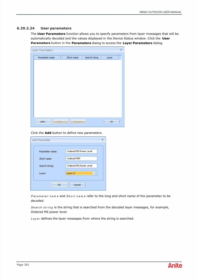
8/16/2019 Nemo Outdoor User Manual
http://slidepdf.com/reader/full/nemo-outdoor-user-manual 281/391
NEMO OUTDOOR USER MANUAL
Page 281
6.29.2.24 User parameters
The User Parameters function allows you to specify parameters from layer messages that will beautomatically decoded and the values displayed in the Device Status window. Click the UserParameters button in the Parameters dialog to access the Layer Parameters dialog.
Click the Add button to define new parameters.
P ar a m e t e r n a m e and Sh o r t n a m e refer to the long and short name of the parameter to bedecoded.
S e ar c h s t r i n g is the string that is searched from the decoded layer messages, for example,Ordered MS power level.
L a y e r defines the layer messages from where the string is searched.

8/16/2019 Nemo Outdoor User Manual
http://slidepdf.com/reader/full/nemo-outdoor-user-manual 282/391
NEMO OUTDOOR USER MANUAL
Page 282
After you have defined all the parameters, click OK . The new parameter is added to the list in theLayer Parameters dialog. Click OK to exit the dialog. In the Parameters dialog, expand the UserParameters item. Select the parameter you just defined and click OK .
The list of user parameters that you have defined are saved in a file called Parameters.xml .
User Parameters can be searched in messages grids. The user can also perform more complex
searches where the search key is split across multiple rows of data. It is possible, for example, tosearch and display multiple results in a single Layer 3 message.
It is possible to export and import user parameters from and to Nemo Outdoor. See chapterExport/import settings for more information.
6.30 Viewing maps
Nemo Outdoor supports two types of outdoor maps: MapX and OpenStreetMap maps. Most of thefunctions are the same for both types but there are some differences.
♦ Please note that in order to use OpenStreetMap maps, the computer needs to beconnected to the Internet or OpenStreetMap data must be downloaded on the computer.

8/16/2019 Nemo Outdoor User Manual
http://slidepdf.com/reader/full/nemo-outdoor-user-manual 283/391
NEMO OUTDOOR USER MANUAL
Page 283
Open a map by selecting Data | Map | New MapX or New OpenStreetMap . If you open a newMapX map, Nemo Outdoor will open by default the map that you have entered in the Default Map field in the User Interface Properties dialog, Paths tab. If you open an OpenStreetMap map, theview will center on your current location.
The map window specific commands can be accessed through toolbar buttons as well as from thepopup menu when right-clicking on the map. See chapter Map toolbar buttons for a description ofthe Nemo Outdoor map toolbar buttons.
♦ Note that the Indoor map differs from the example below. For information on Indoormeasurements, refer to chapter Viewing indoor maps.
It is possible to view selected parameters on a map by drag and dropping them in it. Click on aparameter in the Parameters view and drag and drop it on the map. Parameters can also be openedfor all devices at once and seen on different views. First, press down the Ctrl button and select thedevices by clicking on them in the parameter tree. After this, right-click on the parameter you wishto view from the parameter tree and select Open in Map from the drop-down menu.
If you have a GPS receiver connected to the test system, the current location of the test vehicle willbe displayed on the map as a circle on the route. If there is no GPS connected to the system, youcan define the current location manually with the Set Current Location tool (the button isactivated when recording is started). A new GPS event is created in the handler after which alllocation-specific data, such as BTS cell names are displayed using the specified location.
You can observe the values of certain network parameters from the route coloring on the map. Youcan define which color refers to which parameter value. This way it is easy to spot the problemareas on a map.

8/16/2019 Nemo Outdoor User Manual
http://slidepdf.com/reader/full/nemo-outdoor-user-manual 284/391

8/16/2019 Nemo Outdoor User Manual
http://slidepdf.com/reader/full/nemo-outdoor-user-manual 285/391
NEMO OUTDOOR USER MANUAL
Page 285
6.30.1.1 Editing BTS files in Nemo Outdoor
It is possible to edit the locations of base station icons directly in Nemo Outdoor. Open a BTS file ona map. Right-click on a BTS icon and select Move . Then click on the new location and the BTS iconis moved there. You can also remove BTS sites from the BTS file. The changes are saved in the BTS
file when you exit Nemo Outdoor.
Right-click on a BTS icon and select Edit or right-click on the map and select Add Site . In the BTSEditor you can edit the site and cell information. You can also add new sites, cells, and neighborcells by clicking the Add button.
For sites, you must define the following information: site name, longitude, and latitude.

8/16/2019 Nemo Outdoor User Manual
http://slidepdf.com/reader/full/nemo-outdoor-user-manual 286/391
NEMO OUTDOOR USER MANUAL
Page 286
Under sites you have cells. For cells there are some mandatory and optional settings.
The settings below are mandatory.
S y s t e m defines in which cellular system the cell belongs.
Ce l l n a m e defines a unique name for the cell.
A n t e n n a d i r e ct i o n defines the direction of the antenna in degrees.
Ch a n n e l n u m b e r defines the channel number.
Ce l l I D / Ce l l I D 1 6 - b i t defines a unique cell ID for the cell.
R ad i o n e t w o r k c o n t r o l le r I D defines a unique radio network controller ID for the cell.
S cr a m b l i n g c o d e defines a unique scrambling code for the cell.
The settings below are optional.
A n t e n n a h e i g h t defines the height of the antenna from the ground in meters.
A n t e n n a t i l t defines the angle of the main beam of the antenna relative to the horizontal plane.
A n t e n n a b e a m w i d t h defines the width of the beam in degrees.
Ce l l r a n g e defines the range of the cell in kilometers.
For Cell type the options are undefined, normal, and repeater.L o c a t io n a r e a c o d e defines in which location area the cell belongs.
R o u t i n g a r e a c o d e defines in which routing area the cell belongs.
U T RA N r e g i s t r a t i o n a r e a defines in which UTRAN registration area the cell belongs.
6.30.2 MapX maps
You can customize the MapX map view using the MapX properties. The customized settings can besaved in a MapInfo Geoset file (.gst) and loaded later on. MapInfo Workspaces (*.wor file) cannotbe directly opened with MapX, but can be saved as a .gst file in MapInfo Professional using the
MapInfo MapX Geoset Utility tool (Geoset.mbx) that ships with version 5.x of MapInfo Professional.This file (.gst) can be directly opened by MapX in Nemo Outdoor.
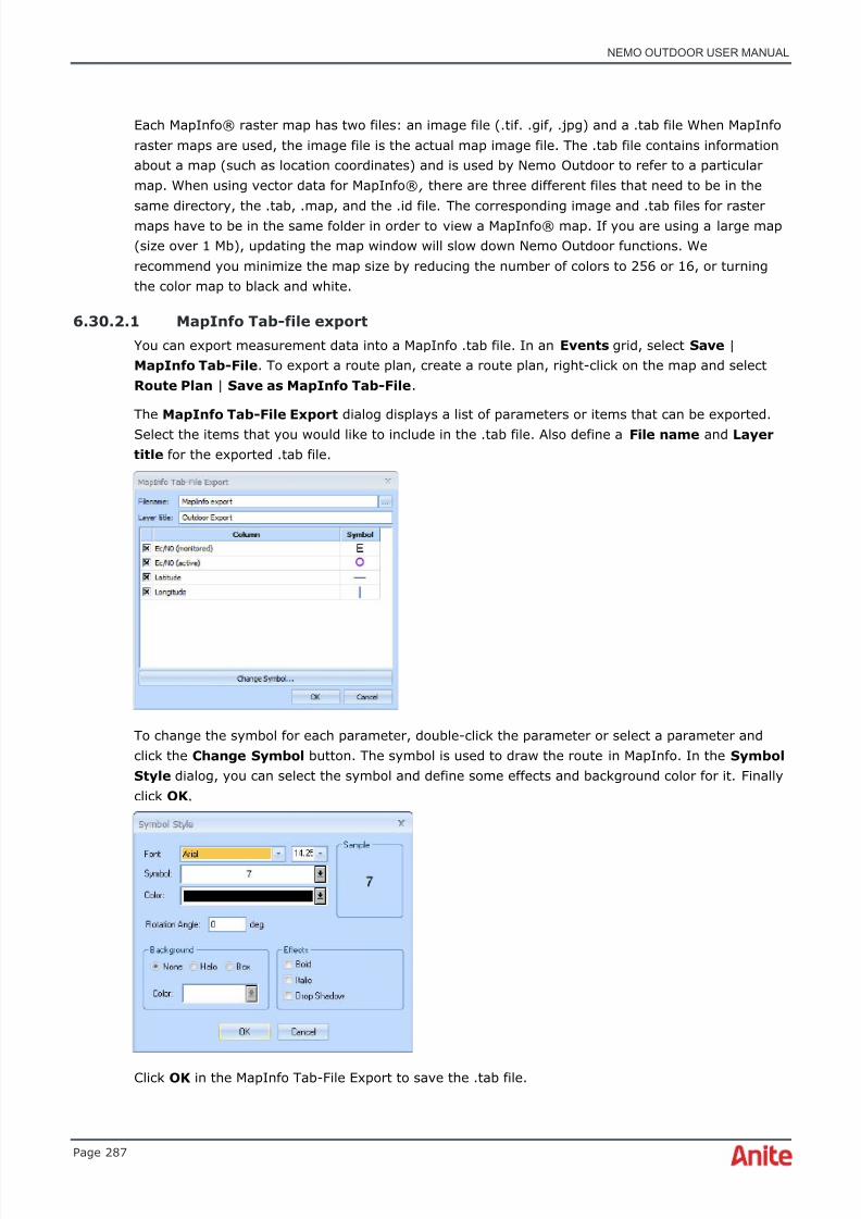
8/16/2019 Nemo Outdoor User Manual
http://slidepdf.com/reader/full/nemo-outdoor-user-manual 287/391
NEMO OUTDOOR USER MANUAL
Page 287
Each MapInfo® raster map has two files: an image file (.tif. .gif, .jpg) and a .tab file When MapInforaster maps are used, the image file is the actual map image file. The .tab file contains informationabout a map (such as location coordinates) and is used by Nemo Outdoor to refer to a particularmap. When using vector data for MapInfo® , there are three different files that need to be in thesame directory, the .tab, .map, and the .id file. The corresponding image and .tab files for rastermaps have to be in the same folder in order to view a MapInfo® map. If you are using a large map(size over 1 Mb), updating the map window will slow down Nemo Outdoor functions. Werecommend you minimize the map size by reducing the number of colors to 256 or 16, or turningthe color map to black and white.
6.30.2.1 MapInfo Tab-file export
You can export measurement data into a MapInfo .tab file. In an Events grid, select Save |MapInfo Tab-File . To export a route plan, create a route plan, right-click on the map and selectRoute Plan | Save as MapInfo Tab-File .
The MapInfo Tab-File Export dialog displays a list of parameters or items that can be exported.Select the items that you would like to include in the .tab file. Also define a File name and Layertitle for the exported .tab file.
To change the symbol for each parameter, double-click the parameter or select a parameter andclick the Change Symbol button. The symbol is used to draw the route in MapInfo. In the SymbolStyle dialog, you can select the symbol and define some effects and background color for it. Finallyclick OK .
Click OK in the MapInfo Tab-File Export to save the .tab file.
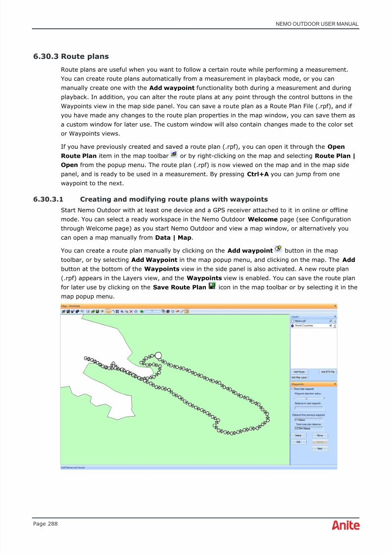
8/16/2019 Nemo Outdoor User Manual
http://slidepdf.com/reader/full/nemo-outdoor-user-manual 288/391
NEMO OUTDOOR USER MANUAL
Page 288
6.30.3 Route plans
Route plans are useful when you want to follow a certain route while performing a measurement.You can create route plans automatically from a measurement in playback mode, or you canmanually create one with the Add waypoint functionality both during a measurement and during
playback. In addition, you can alter the route plans at any point through the control buttons in theWaypoints view in the map side panel. You can save a route plan as a Route Plan File (.rpf), and ifyou have made any changes to the route plan properties in the map window, you can save them asa custom window for later use. The custom window will also contain changes made to the color setor Waypoints views.
If you have previously created and saved a route plan (.rpf), you can open it through the OpenRoute Plan item in the map toolbar or by right-clicking on the map and selecting Route Plan |Open from the popup menu. The route plan (.rpf) is now viewed on the map and in the map sidepanel, and is ready to be used in a measurement. By pressing Ctrl+A you can jump from onewaypoint to the next.
6.30.3.1 Creating and modifying route plans with waypoints
Start Nemo Outdoor with at least one device and a GPS receiver attached to it in online or offlinemode. You can select a ready workspace in the Nemo Outdoor Welcome page (see Configurationthrough Welcome page) as you start Nemo Outdoor and view a map window, or alternatively youcan open a map manually from Data | Map .
You can create a route plan manually by clicking on the Add waypoint button in the maptoolbar, or by selecting Add Waypoint in the map popup menu, and clicking on the map. The Add button at the bottom of the Waypoints view in the side panel is also activated. A new route plan(.rpf) appears in the Layers view, and the Waypoints view is enabled. You can save the route planfor later use by clicking on the Save Route Plan icon in the map toolbar or by selecting it in themap popup menu.

8/16/2019 Nemo Outdoor User Manual
http://slidepdf.com/reader/full/nemo-outdoor-user-manual 289/391
NEMO OUTDOOR USER MANUAL
Page 289
You can define waypoint-related settings in the Waypoint view in the side bar. The Show nextwaypoint option should be selected when you want to view the next waypoint on the map during ameasurement. Note that the Show next waypoint functionality is only enabled in online or idlemode, not during playback. The next waypoint is shown on the route as a big circle. If you clear theShow next waypoint option, the Waypoint detection radius and Distance to next waypoint items will also be disabled.
The Waypoint detection radius slider indicates at which distance (meters) the next waypoint isselected. As you approach the next waypoint during a measurement, the next waypoint is selectedon the map when distance to it is smaller than the distance selected in the slide bar. The Distanceto next waypoint field indicates how many meters there still are to the next waypoint from thecurrent position on the route, so the figure decreases as you approach the next waypoint. TheDistance from previous waypoint field indicates how many meters it is from the previouswaypoint from the current position on the route. With the Next button you can move from onewaypoint to the next.
You can make changes to the route plan using the buttons at the bottom of the Waypoints view.
To select a waypoint on the map, click on the Select button in the Waypoints view, then select awaypoint on the map. This waypoint is shown as a bigger circle than the others. In addition, thedelete functionality is only enabled when the Select button is selected. If you click on Delete , theselected waypoint on the route plan will be deleted, and the previous waypoint on the route willautomatically be selected and shown as a bigger circle. If the deleted waypoint was the firstwaypoint on the route plan, the next waypoint on the route will be selected. Moreover, the Delete button is only enabled with the Select button if there is more than one waypoint on the map.Reclick on Select to clear the functionality.
You can move waypoints on the map by first clicking on Select , then selecting a specific waypointon the map. Click on the Move button, and you will be able to move the selected waypoint on themap. The part of the route attached to the waypoint is moved with the waypoint. With the Reverse button you can reverse the direction of the route plan.

8/16/2019 Nemo Outdoor User Manual
http://slidepdf.com/reader/full/nemo-outdoor-user-manual 290/391
NEMO OUTDOOR USER MANUAL
Page 290
The Add button in the Waypoints view in the side panel is synchronized with the Add waypoint button in the map toolbar. If you click on either button when they are inactive, they will both be
activated, and conversely if you click on either button when active, they will become inactive. Whenyou select either, you are able to place new waypoints in the route plan.
6.30.3.2 Creating and saving route plans from a measurement
In addition to creating a route plan with waypoints, you can create a route plan from ameasurement.
Start Nemo Outdoor, load a measurement file and open a map window. Right-click on the map andselect View Entire Route , or zoom in on the map to make sure the measurement contains GPScoordinates. Create a route plan by clicking the Create Route Plan toolbar icon, or selectRoute Plan | Create from the map popup menu. The route plan should now be visible on the map,the layer list should have a new layer (“Untitled.rpf”), and the control buttons on the Waypoints view should be enabled. The route plan should closely follow the route from which it was created.Save the route plan by clicking the Save Route Plan item in the toolbar, or by selecting it in themap popup menu.
You can also modify the route plan with the Select, Move, Add and Delete buttons at the bottomof the Waypoints view in the side panel. Note that when you click on Select, you may need to zoomin on the map to view the discrete waypoints. The selected waypoint will show as a bigger circleamong all the circles. See chapter Creating and modifying route plans with waypoints for moreinformation on how to use the control buttons, and on how to read the waypoints on the route planduring a measurement.
6.30.3.3 Saving a route plan to a custom window
When you create a route plan and save it, the actual route plan will be saved as a Route Plan File
(.rpf). However, if you have made changes to the default map window and to the layer-specificproperties, and you want to save these changes, you need to save the map window as a customwindow. When you open a measurement the next time, you can open the custom window by right-clicking on the gray space outside the map window, and select Map | [name of custom window] .You will also find the custom window in Data | Map | [name of custom window] .
First, create or open a route plan, and save it. Next, double-click on the route plan in the map sidepanel to access the Route Plan Properties dialog, change the properties and click OK . Change thesettings in the Waypoints view in the side panel, right-click on the map, and select Save AsCustom Window in the map popup menu. Close the map and open the custom window you saved.When you open the properties dialog, the properties should be what you set them to.

8/16/2019 Nemo Outdoor User Manual
http://slidepdf.com/reader/full/nemo-outdoor-user-manual 291/391
NEMO OUTDOOR USER MANUAL
Page 291
6.30.4 Map popup menu
Right-click on the map to open a popup menu with various tools for configuring the layout of themap. Please note that the contents of the menu depend on the map type (MapX orOpenStreetMap).

8/16/2019 Nemo Outdoor User Manual
http://slidepdf.com/reader/full/nemo-outdoor-user-manual 292/391
NEMO OUTDOOR USER MANUAL
Page 292
6.30.4.1 Custom Window Properties dialog
In the Custom Window Properties dialog you can define the custom window name and selectgroups for the custom windows. The custom window groups define which custom windows areavailable for each device. For example, if you select LTE FDD, the custom window will only beavailable when an LTE device is added to Nemo Outdoor or you are playing back an LTEmeasurement.
6.30.4.2 Save as new custom window
Right-click on a graph window and select Save as New Custom Window from the popup menu.The Custom Window Properties dialog is opened (see above). Type a name for the customwindow and define the custom window groups.
6.30.4.3 Save custom window changes
Use the Save Custom Window Changes command to save changes made in the custom window.
6.30.4.4 Save as - CSV file
Use the Save as Image command to export the active view into CSV format.
6.30.4.5 Save as - Image
Use the Save as Image command to save the active view as a .jpg image.
6.30.4.6 Save as - MapInfo Tab-file
Use the Save as MapInfo Tab-file command to export the active view into MapInfo format.

8/16/2019 Nemo Outdoor User Manual
http://slidepdf.com/reader/full/nemo-outdoor-user-manual 293/391

8/16/2019 Nemo Outdoor User Manual
http://slidepdf.com/reader/full/nemo-outdoor-user-manual 294/391
NEMO OUTDOOR USER MANUAL
Page 294
6.30.4.12 Download tiles
With the Download Tiles tool you can download OpenStreetMap data on your computer so you canuse the OpenStreetMap maps even when you are not connected to the Internet.
♦ It is recommended to use this method always with OpenStreetMap maps as downloading
map data in the middle of measurements may affect the results.
Z o o m l e v e l s defines the number of levels from which map data is downloaded. The more levelsyou choose, the more data is downloaded.
Select the R e lo a d e x i s t i n g t i le s option to overwrite existing map data.
Click the S e l e ct A r e a button to the select an area with your mouse from where map data will bedownloaded.
6.30.4.13 Empty disk cache
Select the Empty Disk Cache option to delete all downloaded OpenStreetMap data. The tiles openon the map will not be deleted.
6.30.4.14 Route plan - Create
The Create Route Plan item creates a route plan from an open measurement in a map window.
6.30.4.15 Route plan - Open
Through the Open Route Plan item you can open saved route plans to be viewed on a map.
6.30.4.16 Route plan - Save
The Save Route Plan item will let you save the route plan as a Route Plan File (.rpf) for later use.
6.30.4.17 Route plan - Save as MapInfo Tab-file
The Save Route Plan as MapInfo Tab-File item will let you save the route plan as a .tab file thatcan be opened in MapInfo. See chapter MapInfo Tab-file export for more information.
6.30.4.18 Add waypoint
Activates the add waypoint functionality for creating route plans manually.

8/16/2019 Nemo Outdoor User Manual
http://slidepdf.com/reader/full/nemo-outdoor-user-manual 295/391
NEMO OUTDOOR USER MANUAL
Page 295
6.30.4.19 Tool
Tool pull-down menu offers a selection of settings for configuring the window setup.
Arrow tool changes the cursor back to an arrow.
Pan tool changes the cursor into a hand that can scroll the map.
Center tool allows the map to be centered according to the cursor point.
Zoom In and Zoom Out tools change the cursor into a magnifying glass. You can also zoom in andout using the mouse wheel and the + and - keyboard buttons.
Clear Route tool removes the measurement route from the map. Note that this command isactivated only during measurements. It cannot be used during playback.
Set Current Location tool defines the current location when no GPS data is available. Note thatthis command is activated only during measurements and when no GPS is connected. It cannot beused during playback.
6.30.4.20 Auto center
The Auto Center tool pans the map so that the current location will stay on the visible area of themap. Note that you cannot use the Pan and Center tools when the Auto Center command isselected.
6.30.4.21 Auto clear route
The Auto Clear Route tool automatically removes the route from the map when measurement isstopped. If you wish to keep the route on the map when starting a new measurement, unselect thetool.
6.30.4.22 Previous view and view entire map
With the Previous View command, you can return to the previous map view, and the View EntireMap command displays the whole map.
6.30.4.23 View entire route
By selecting the View Entire Route item you will be able to view the whole route on the map.
6.30.4.24 Scale
The Scale appears in the window when the respective selection is activated.
6.30.4.25 Modify route
With the Modify Route tool you can modify and reposition the measurement route in playback.
This is especially useful if there is a gap in the measurement route, for example, because GPS fixwas lost in a tunnel.

8/16/2019 Nemo Outdoor User Manual
http://slidepdf.com/reader/full/nemo-outdoor-user-manual 296/391
NEMO OUTDOOR USER MANUAL
Page 296
Right-click on a map and select Modify Route from the popup menu.
The route will be displayed as dots.

8/16/2019 Nemo Outdoor User Manual
http://slidepdf.com/reader/full/nemo-outdoor-user-manual 297/391

8/16/2019 Nemo Outdoor User Manual
http://slidepdf.com/reader/full/nemo-outdoor-user-manual 298/391
NEMO OUTDOOR USER MANUAL
Page 298
6.30.4.27 Textual comments
With the Textual Comments tool you can add textual comments on the map. Select Add TextualComment from the menu and type in the text box that appears on the map. The box can berepositioned by dragging it on the map. To remove or edit individual comments, right-click on the
text box and select Remove or Edit . To remove all comments, right-click on the map and selectTextual Comments | Remove All Textual Comments .
6.30.4.28 Side panels
6.30.4.29 Color legends
The Color legends view shows the selected color set for a measurement route. If you have loadeda multi measurement and added multiple routes with assigned color sets on the map, the colorlegends will be shown in separate tabs. See chapter Color Set Editor on how to create and edit colorsets.
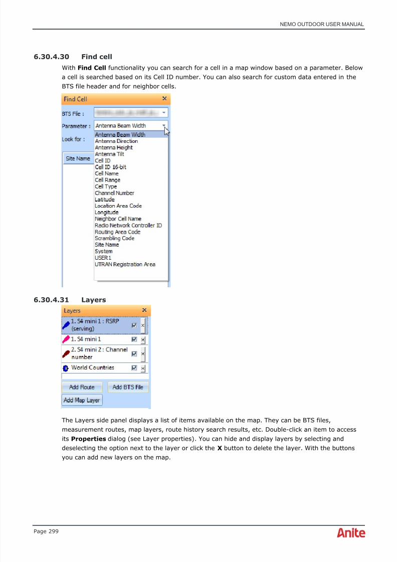
8/16/2019 Nemo Outdoor User Manual
http://slidepdf.com/reader/full/nemo-outdoor-user-manual 299/391
NEMO OUTDOOR USER MANUAL
Page 299
6.30.4.30 Find cell
With Find Cell functionality you can search for a cell in a map window based on a parameter. Belowa cell is searched based on its Cell ID number. You can also search for custom data entered in theBTS file header and for neighbor cells.
6.30.4.31 Layers
The Layers side panel displays a list of items available on the map. They can be BTS files,measurement routes, map layers, route history search results, etc. Double-click an item to accessits Properties dialog (see Layer properties) . You can hide and display layers by selecting anddeselecting the option next to the layer or click the X button to delete the layer. With the buttonsyou can add new layers on the map.

8/16/2019 Nemo Outdoor User Manual
http://slidepdf.com/reader/full/nemo-outdoor-user-manual 300/391
NEMO OUTDOOR USER MANUAL
Page 300
6.30.4.32 Measure distance
Use the Measure Distance tool to measure the distance between multiple points on a map. Clickthe Measure Distance button to activate the tool and click the Add point button. Select thepoints on the map and the distance between these points is displayed on the map. The Total
distance is displayed in the left-hand panel.
With the Draw distance circle tool you can draw a circle where the distance between the last twopoints is used as the radius.
To remove points from the map, click the Remove latest point or Remove all points buttons. Tohide the Measure Distance panel, click the Measure Distance button.

8/16/2019 Nemo Outdoor User Manual
http://slidepdf.com/reader/full/nemo-outdoor-user-manual 301/391
NEMO OUTDOOR USER MANUAL
Page 301
6.30.4.33 Route history
If the Route History side panel is not visible, right-click on the map and select Side Panels | RouteHistory . With the Route History tool you can search for measurements recorded within a specifiedtime frame and plot those measurement routes on a map. This requires that a GPX file has beencreated for the measurement. Define the folder from where GPX files will be searched and definethe time frame. After you click the Search button, Outdoor will search for the GPX files and displaythe matching routes on the map.
The search results will also be displayed as layers. Double-click the route history layer to open theRoute History Route Properties dialog where you can edit the route color and thickness.
6.30.4.34 Waypoints
The waypoints item will activate the free route planning functionality on the map. You can createand save a route plan for later use. The Show next waypoint field is only activated when at leastone device and one GPS receiver are attached to Nemo Outdoor in online or offline mode. Thisfunctionality is not active during measurement playback. See chapter Creating and modifying routeplans with waypoints for more information.
6.30.4.35 Full screen
Selecting the Full screen item will display Nemo Outdoor in full screen mode.

8/16/2019 Nemo Outdoor User Manual
http://slidepdf.com/reader/full/nemo-outdoor-user-manual 302/391
NEMO OUTDOOR USER MANUAL
Page 302
6.30.4.36 Layer properties
The dialog appearing when you click on the Layer Properties item depends on the layer selected inthe map side panel. It is possible to view three different kinds of layers in the side panel: thedevice-specific measurement route layer, the base station layer, and the route plan layer.
6.30.4.37 Route properties
In the Route Properties dialog, you can define map-related settings.
D e v i c e defines the device that is being viewed on the map.
Select the S h o w D e v i ce L a b e l n e x t t o r o u t e option to display the device name at the startingpoint of the measurement route.
Click the MapX Properties button to define some MapX specific properties. Note that thesesettings differ according to the map provider. These settings can be saved in a MapInfo Geoset fileby clicking the Save Map button in the Map window.
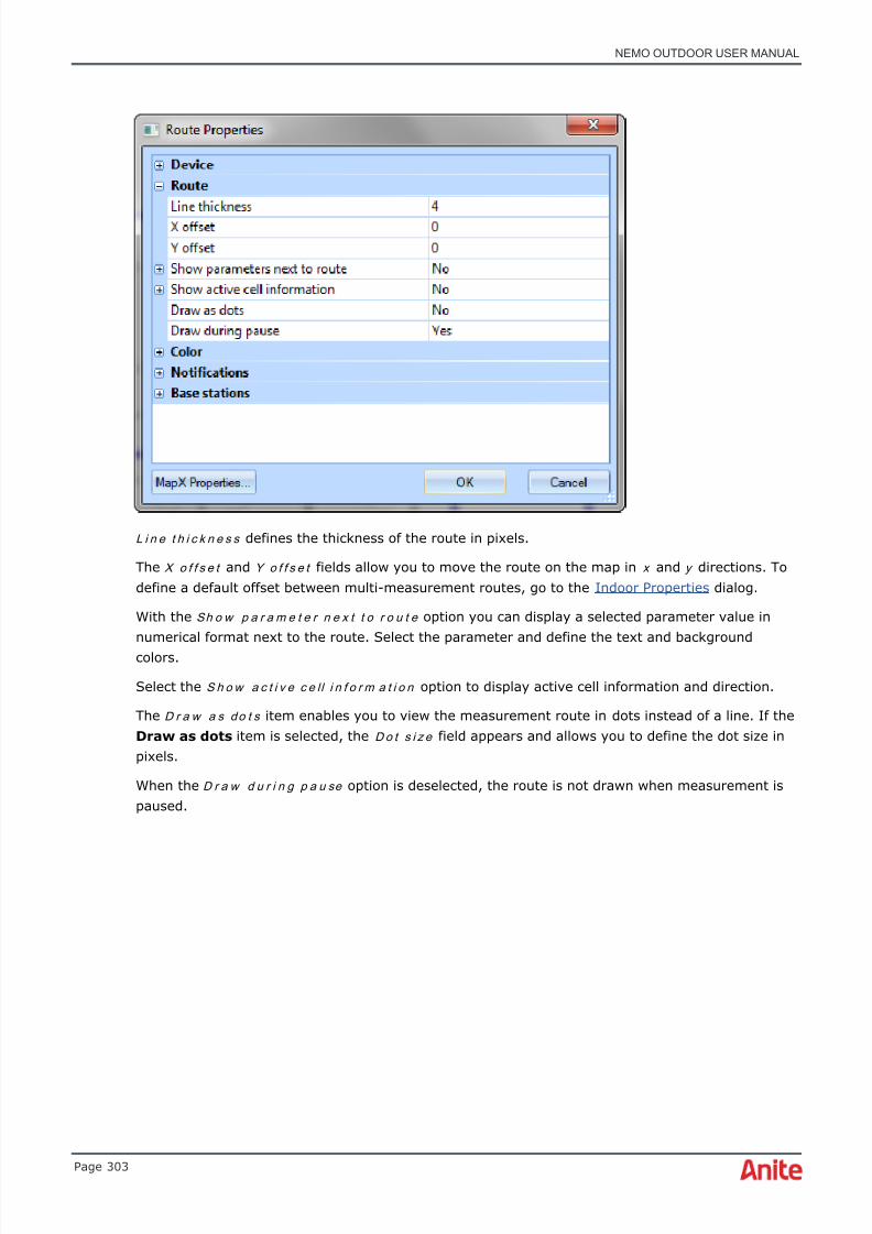
8/16/2019 Nemo Outdoor User Manual
http://slidepdf.com/reader/full/nemo-outdoor-user-manual 303/391
NEMO OUTDOOR USER MANUAL
Page 303
L i n e t h i c k n e s s defines the thickness of the route in pixels.
The X o f f s e t and Y o f f s e t fields allow you to move the route on the map in x and y directions. Todefine a default offset between multi-measurement routes, go to the Indoor Properties dialog.
With the Sh o w p a r a m e t e r n e x t t o r o u t e option you can display a selected parameter value innumerical format next to the route. Select the parameter and define the text and backgroundcolors.
Select the S h o w a c t i v e c e l l i n f o r m a t i o n option to display active cell information and direction.
The D r a w a s d o t s item enables you to view the measurement route in dots instead of a line. If theDraw as dots item is selected, the D o t s i z e field appears and allows you to define the dot size inpixels.
When the D r a w d u r i n g p a u se option is deselected, the route is not drawn when measurement ispaused.
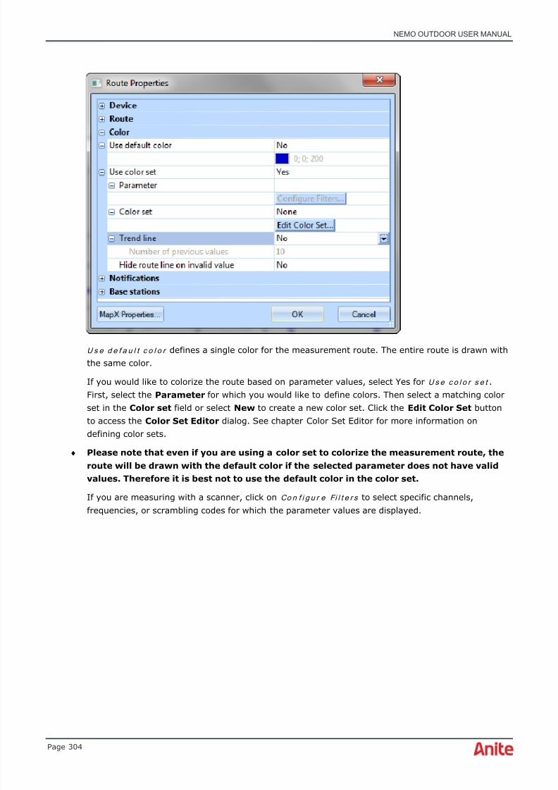
8/16/2019 Nemo Outdoor User Manual
http://slidepdf.com/reader/full/nemo-outdoor-user-manual 304/391
NEMO OUTDOOR USER MANUAL
Page 304
U s e d e f a u l t c o l o r defines a single color for the measurement route. The entire route is drawn withthe same color.
If you would like to colorize the route based on parameter values, select Yes for U s e c o l o r s e t .First, select the Parameter for which you would like to define colors. Then select a matching colorset in the Color set field or select New to create a new color set. Click the Edit Color Set buttonto access the Color Set Editor dialog. See chapter Color Set Editor for more information ondefining color sets.
♦ Please note that even if you are using a color set to colorize the measurement route, theroute will be drawn with the default color if the selected parameter does not have validvalues. Therefore it is best not to use the default color in the color set.
If you are measuring with a scanner, click on Co n f i g u r e Fi l t e r s to select specific channels,frequencies, or scrambling codes for which the parameter values are displayed.

8/16/2019 Nemo Outdoor User Manual
http://slidepdf.com/reader/full/nemo-outdoor-user-manual 305/391
NEMO OUTDOOR USER MANUAL
Page 305
To filter spectrum scanning results, define the frequency exactly in the same format as it appears inthe Spectrum graph.
To select scrambling codes, first select a channel by clicking the Select button under Selectedchannel numbers . Then select scrambling codes for the selected channel by clicking the Select button under Selected scrambling codes .
If you would like to use averaging in drawing the route, select the T r e n d l i n e option and selectfrom the N u m b e r o f p r e v i o u s v a l u e s field how many values will be included in the average value.
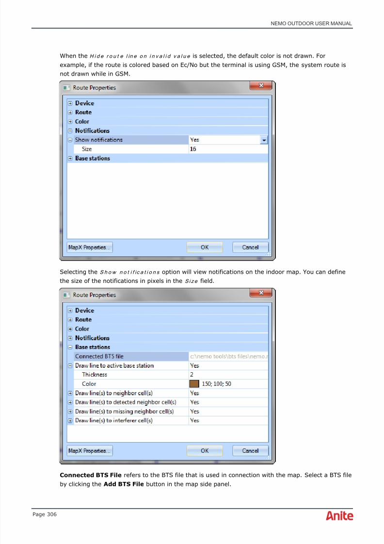
8/16/2019 Nemo Outdoor User Manual
http://slidepdf.com/reader/full/nemo-outdoor-user-manual 306/391
NEMO OUTDOOR USER MANUAL
Page 306
When the H i d e r o u t e l in e o n i n v a l i d v a l u e is selected, the default color is not drawn. Forexample, if the route is colored based on Ec/No but the terminal is using GSM, the system route isnot drawn while in GSM.
Selecting the S h o w n o t i f ic a t i o n s option will view notifications on the indoor map. You can definethe size of the notifications in pixels in the S i z e field.
Connected BTS File refers to the BTS file that is used in connection with the map. Select a BTS fileby clicking the Add BTS File button in the map side panel.
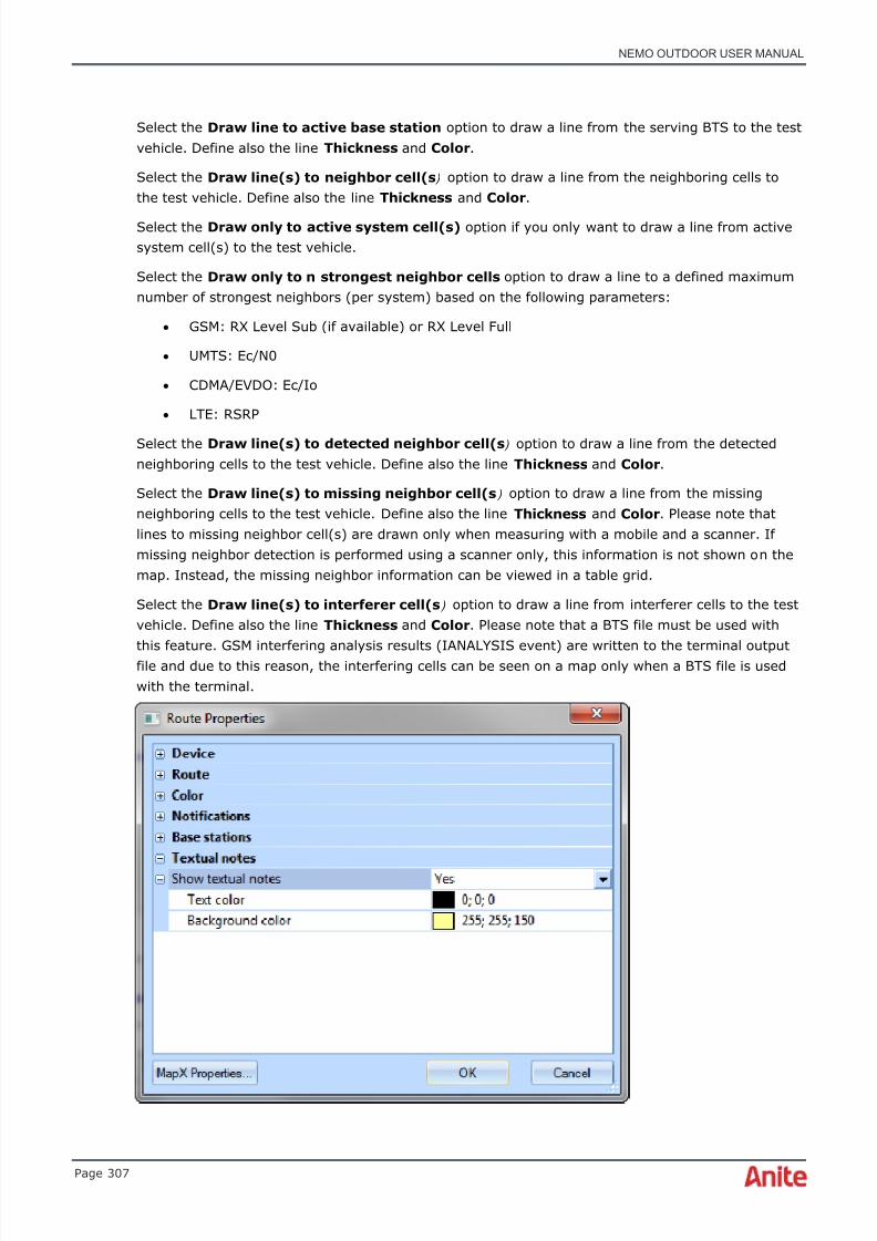
8/16/2019 Nemo Outdoor User Manual
http://slidepdf.com/reader/full/nemo-outdoor-user-manual 307/391
NEMO OUTDOOR USER MANUAL
Page 307
Select the Draw line to active base station option to draw a line from the serving BTS to the testvehicle. Define also the line Thickness and Color .
Select the Draw line(s) to neighbor cell(s ) option to draw a line from the neighboring cells tothe test vehicle. Define also the line Thickness and Color .
Select the Draw only to active system cell(s) option if you only want to draw a line from activesystem cell(s) to the test vehicle.
Select the Draw only to n strongest neighbor cells option to draw a line to a defined maximumnumber of strongest neighbors (per system) based on the following parameters:
• GSM: RX Level Sub (if available) or RX Level Full
• UMTS: Ec/N0
• CDMA/EVDO: Ec/Io
• LTE: RSRP
Select the Draw line(s) to detected neighbor cell(s ) option to draw a line from the detectedneighboring cells to the test vehicle. Define also the line Thickness and Color .
Select the Draw line(s) to missing neighbor cell(s ) option to draw a line from the missingneighboring cells to the test vehicle. Define also the line Thickness and Color . Please note thatlines to missing neighbor cell(s) are drawn only when measuring with a mobile and a scanner. Ifmissing neighbor detection is performed using a scanner only, this information is not shown on themap. Instead, the missing neighbor information can be viewed in a table grid.
Select the Draw line(s) to interferer cell(s ) option to draw a line from interferer cells to the testvehicle. Define also the line Thickness and Color . Please note that a BTS file must be used with
this feature. GSM interfering analysis results (IANALYSIS event) are written to the terminal outputfile and due to this reason, the interfering cells can be seen on a map only when a BTS file is usedwith the terminal.

8/16/2019 Nemo Outdoor User Manual
http://slidepdf.com/reader/full/nemo-outdoor-user-manual 308/391
NEMO OUTDOOR USER MANUAL
Page 308
By selecting the Sh o w T ex t u a l n o t e s option, you will be able to view textual notes on ameasurement route in the map window. You can select a text and background color for the note inthe Te x t c o l o r and B a c k g r o u n d co l o r fields.
Click OK to exit the Route Properties dialog.
6.30.4.38 BTS Properties dialog
When a base station file is selected in the map side panel, the BTS Properties dialog appears whenLayer Properties is selected in the map popup menu. You can also view the dialog by double-clicking on the BTS file in the map side panel.
B T S f i l e refers to the BTS file that is used on the map.
If you have a BTS file that contains base stations from several systems (e.g., UMTS and GSM),select the Draw only active system base stations option to display only base stations from theactive system, in other words, the system in which the test device is currently. The other basestations are hidden.
Define also the size and color of the BTS icons. Note that you define a different color for activesystem base stations and for other base stations.
• S e l e ct e d c e l l c o l o r defines a color for a cell that is selected on the map. Neighboring cellsare highlighted with the selected color and the selected cell is shown with the same colorbut with a bolded outline. The tooltip shows neighbor cell names for the selected cell.
• S e r v i n g c e l l c o l o r defines a color for the currently serving cell.
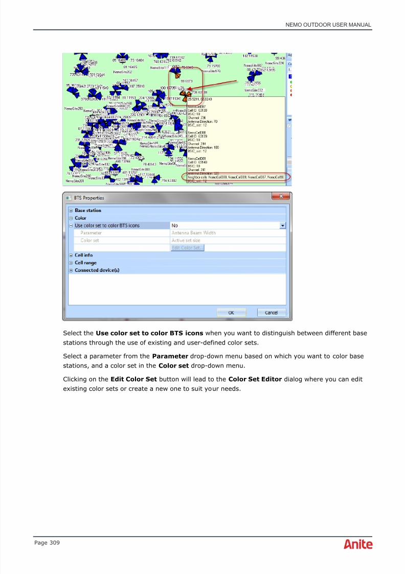
8/16/2019 Nemo Outdoor User Manual
http://slidepdf.com/reader/full/nemo-outdoor-user-manual 309/391
NEMO OUTDOOR USER MANUAL
Page 309
Select the Use color set to color BTS icons when you want to distinguish between different basestations through the use of existing and user-defined color sets.
Select a parameter from the Parameter drop-down menu based on which you want to color basestations, and a color set in the Color set drop-down menu.
Clicking on the Edit Color Set button will lead to the Color Set Editor dialog where you can editexisting color sets or create a new one to suit your needs.

8/16/2019 Nemo Outdoor User Manual
http://slidepdf.com/reader/full/nemo-outdoor-user-manual 310/391
NEMO OUTDOOR USER MANUAL
Page 310
See chapter Color Set Editor for more information on how to edit and create color sets.
Select the Show labels option to display a label or a description next to the selected cellinformation and define the Text color and Background color .

8/16/2019 Nemo Outdoor User Manual
http://slidepdf.com/reader/full/nemo-outdoor-user-manual 311/391
NEMO OUTDOOR USER MANUAL
Page 311
In the example below, all cell information and the Show labels option are selected.

8/16/2019 Nemo Outdoor User Manual
http://slidepdf.com/reader/full/nemo-outdoor-user-manual 312/391
NEMO OUTDOOR USER MANUAL
Page 312
Select the Draw cell range option to view the cell range on the map. Define the degree of cellrange transparency in the Cell range transparency .
DAS anomaly analysis can be used to automatically perform pass/fail analysis for indoor cells. Seechapter DAS anomaly analysis for more information.
The Connected devices displays a list of devices that you can connect to the base station sites.Note that the BTS sites will not be drawn if no device is selected.

8/16/2019 Nemo Outdoor User Manual
http://slidepdf.com/reader/full/nemo-outdoor-user-manual 313/391
NEMO OUTDOOR USER MANUAL
Page 313
6.30.4.39 Route Plan Properties dialog
When a route plan is selected in the side panel and you right-click on the map and select LayerProperties , the Route Plan Properties dialog appears. You can also view the dialog by double-clicking on the route plan in the map side panel.
Route plan file field defines the name of the route plan you selected in the map side panel.
The Waypoint properties field allows you to define the color for the waypoint icon and the lineattaching the icons together. You can also define the icon size and line thickness in pixels.
The X offset and Y offset fields allow you to move the route plan on the map in x and y directions.
6.30.4.40 Map Properties dialog
In the Map Properties dialog you can define the offset (in pixels) between routes on a map. Thisvalue is used with multi measurements where you have multiple routes which, without offset, wouldoverlap each other. You can also disable the default offset completely. To define offset values forindividual routes, go to the Route properties dialog and define the X and Y offset values.
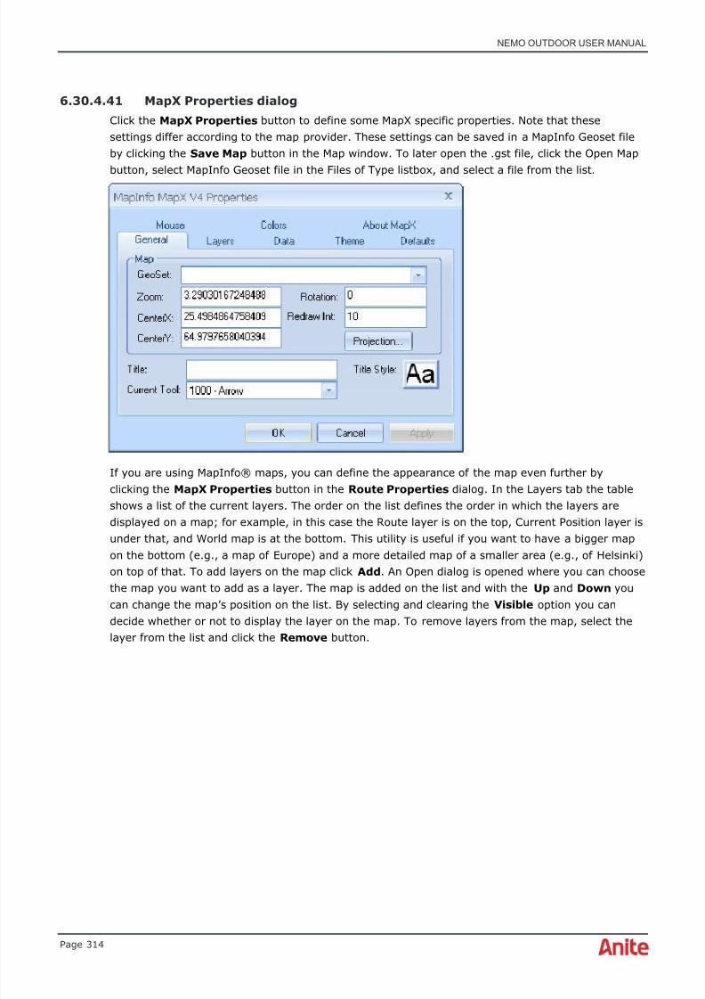
8/16/2019 Nemo Outdoor User Manual
http://slidepdf.com/reader/full/nemo-outdoor-user-manual 314/391
NEMO OUTDOOR USER MANUAL
Page 314
6.30.4.41 MapX Properties dialog
Click the MapX Properties button to define some MapX specific properties. Note that thesesettings differ according to the map provider. These settings can be saved in a MapInfo Geoset fileby clicking the Save Map button in the Map window. To later open the .gst file, click the Open Map
button, select MapInfo Geoset file in the Files of Type listbox, and select a file from the list.
If you are using MapInfo® maps, you can define the appearance of the map even further byclicking the MapX Properties button in the Route Properties dialog. In the Layers tab the tableshows a list of the current layers. The order on the list defines the order in which the layers are
displayed on a map; for example, in this case the Route layer is on the top, Current Position layer isunder that, and World map is at the bottom. This utility is useful if you want to have a bigger mapon the bottom (e.g., a map of Europe) and a more detailed map of a smaller area (e.g., of Helsinki)on top of that. To add layers on the map click Add . An Open dialog is opened where you can choosethe map you want to add as a layer. The map is added on the list and with the Up and Down youcan change the map’s position on the list. By selecting and clearing the Visible option you candecide whether or not to display the layer on the map. To remove layers from the map, select thelayer from the list and click the Remove button.
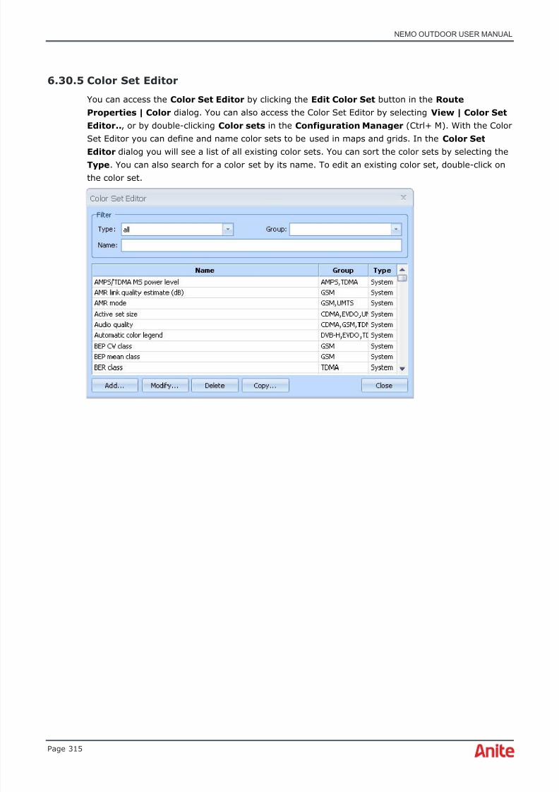
8/16/2019 Nemo Outdoor User Manual
http://slidepdf.com/reader/full/nemo-outdoor-user-manual 315/391
NEMO OUTDOOR USER MANUAL
Page 315
6.30.5 Color Set Editor
You can access the Color Set Editor by clicking the Edit Color Set button in the RouteProperties | Color dialog. You can also access the Color Set Editor by selecting View | Color SetEditor.. , or by double-clicking Color sets in the Configuration Manager (Ctrl+ M). With the Color
Set Editor you can define and name color sets to be used in maps and grids. In the Color SetEditor dialog you will see a list of all existing color sets. You can sort the color sets by selecting theType . You can also search for a color set by its name. To edit an existing color set, double-click onthe color set.

8/16/2019 Nemo Outdoor User Manual
http://slidepdf.com/reader/full/nemo-outdoor-user-manual 316/391
NEMO OUTDOOR USER MANUAL
Page 316
In the Color Set Properties dialog you can edit the settings for each color set.
N a m e and Sh o r t n a m e identify the color set.
You can also type a description of the color set in the D e s c r i p t i o n field.
Ty p e defines what kind of data the color set is used with, numerical, gradient, string, or automatic.T The Groups and Type settings can be used to sort the color sets in the Color Set Editor dialog.
With the A u t o m a t i c a ll y g e n e r a t e m i ss i n g v a lu e s option you can specify colors for some fixedvalues while the rest are automatically generated. This option can be used with numerical or stringtype of colorset. This is especially useful with parameters with many values (e.g. PNs and scr.code).
Va l u e s table displays the different value ranges and the colors associated with them.
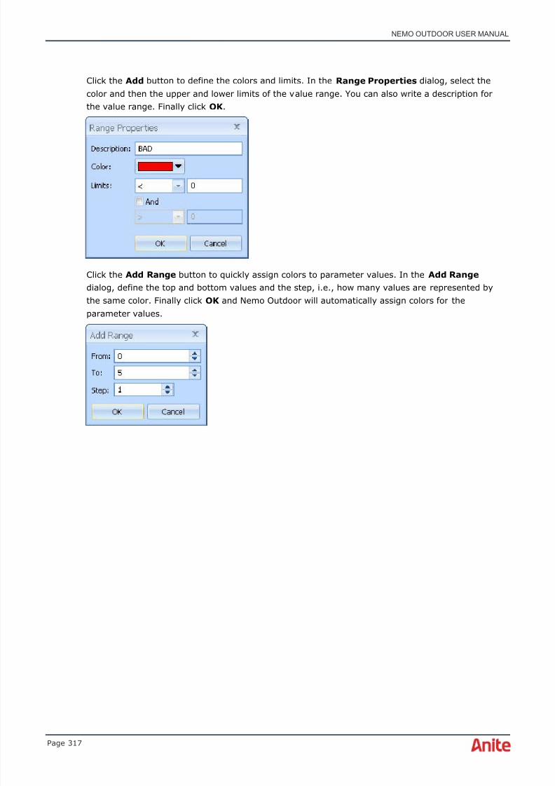
8/16/2019 Nemo Outdoor User Manual
http://slidepdf.com/reader/full/nemo-outdoor-user-manual 317/391
NEMO OUTDOOR USER MANUAL
Page 317
Click the Add button to define the colors and limits. In the Range Properties dialog, select thecolor and then the upper and lower limits of the value range. You can also write a description forthe value range. Finally click OK .
Click the Add Range button to quickly assign colors to parameter values. In the Add Range dialog, define the top and bottom values and the step, i.e., how many values are represented bythe same color. Finally click OK and Nemo Outdoor will automatically assign colors for theparameter values.
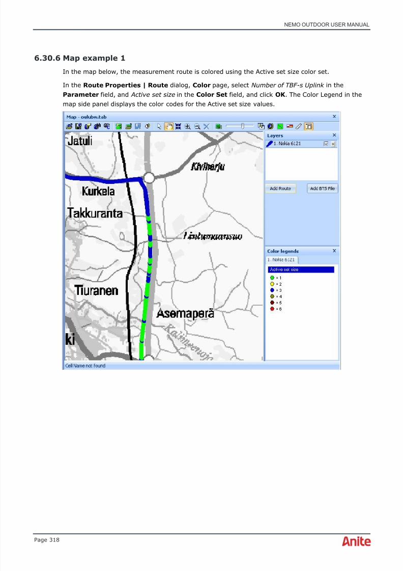
8/16/2019 Nemo Outdoor User Manual
http://slidepdf.com/reader/full/nemo-outdoor-user-manual 318/391
NEMO OUTDOOR USER MANUAL
Page 318
6.30.6 Map example 1
In the map below, the measurement route is colored using the Active set size color set.
In the Route Properties | Route dialog, Color page, select Number of TBF-s Uplink in theParameter field, and Active set size in the Color Set field, and click OK . The Color Legend in themap side panel displays the color codes for the Active set size values.

8/16/2019 Nemo Outdoor User Manual
http://slidepdf.com/reader/full/nemo-outdoor-user-manual 319/391
NEMO OUTDOOR USER MANUAL
Page 319
6.30.7 Map example 2
In the map below, the measurement route is colored using the TX Power color set. In theMeasurement's Route Properties dialog, Color page, select TX Power in the Parameter andColor Set fields and click OK . The Color Legend in the map side panel displays the color codes for
the TX Power values. In this color set, green means a low TX Power level and red a high level.

8/16/2019 Nemo Outdoor User Manual
http://slidepdf.com/reader/full/nemo-outdoor-user-manual 320/391
NEMO OUTDOOR USER MANUAL
Page 320
6.30.8 Map example 3
In the map below, the measurement route is colored using the EcN0 color set. Base station iconsare displayed and a red line is drawn to the serving base station and a blue line to the neighborstations.
In the Layer view in the map side panel, click on Add BTS File, or right-click on the measurementlayer and select Add BTS File. Right-click on the measurement layer in the map side panel again,and select Properties | Base stations . Select the Draw line to active base station , and Drawline(s) to neighbor cell(s) options. On the Color page, select the Use color set option, selectEc/N0 (Active) in the Parameter field, and EcN0 in the Color set field. Click OK . The Color Legendin the side panel displays the color codes for the EcNo values.

8/16/2019 Nemo Outdoor User Manual
http://slidepdf.com/reader/full/nemo-outdoor-user-manual 321/391
NEMO OUTDOOR USER MANUAL
Page 321
6.30.9 Map example 4
In the map below, the same measurement route is drawn twice on the map. The route with the bluecurrent location symbol is colored using the Ec/N0 color set, and the route with the black currentlocation symbol is colored using the MS Power Level color set.
In the Layers view click the Add Route button, or right-click on the existing measurement layerand select Add Route . Select a device from the Route Properties | Device page, and now thereshould be two measurements in the Layers view in the side panel. Right-click on the firstmeasurement route and select Properties . On the Route Properties | Color page, select the Usecolor set option, and Ec/N0(active) in the Parameter field, and Ec/N0 in the Color set field. ClickOK .
Next, right-click on the second measurement in the Layers view, and select Properties . In theRoute Properties | Color page, select the Use color set option, and MS Power Level in theParameter field, and MS Power Level in the Color set field. Click OK .
You will see the two adjacent routes colored with the above-mentioned color sets on the map. Inaddition, you will see the measurements in the Layers view, and their color sets in the Colorlegends view in the map side panel.
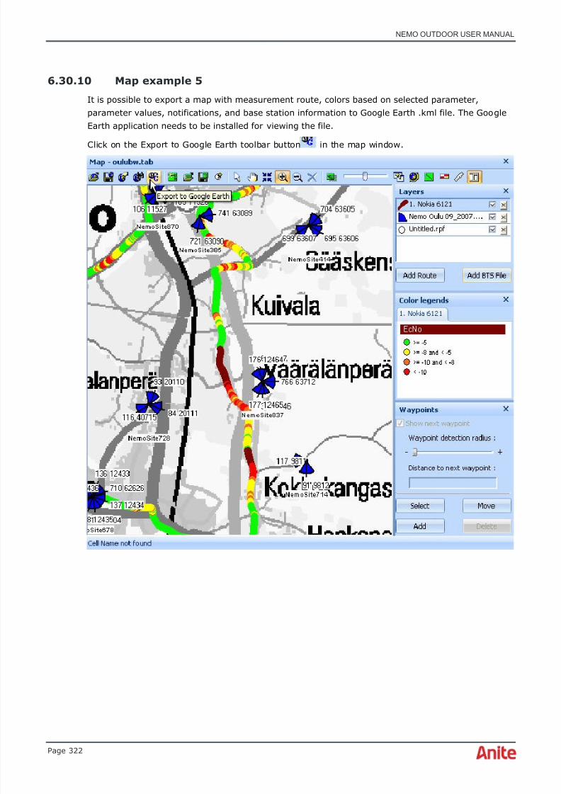
8/16/2019 Nemo Outdoor User Manual
http://slidepdf.com/reader/full/nemo-outdoor-user-manual 322/391
NEMO OUTDOOR USER MANUAL
Page 322
6.30.10 Map example 5
It is possible to export a map with measurement route, colors based on selected parameter,parameter values, notifications, and base station information to Google Earth .kml file. The GoogleEarth application needs to be installed for viewing the file.
Click on the Export to Google Earth toolbar button in the map window.

8/16/2019 Nemo Outdoor User Manual
http://slidepdf.com/reader/full/nemo-outdoor-user-manual 323/391
NEMO OUTDOOR USER MANUAL
Page 323
A Save As dialog appears. Select a destination for the saved .kml file in the Save in field, and typea name for the map to be exported in the File name field. Click Save .
Go to the file destination and double-click on the saved file to open it. Note that you must haveGoogle Earth installed on your laptop to view the file.
The route and cell information are visible on the Google Earth map.

8/16/2019 Nemo Outdoor User Manual
http://slidepdf.com/reader/full/nemo-outdoor-user-manual 324/391
NEMO OUTDOOR USER MANUAL
Page 324
6.30.11 Map Example 6
With scanner measurements, it is possible to view parameter values for a specific channel orscrambling code on a map. In this example we will view RX level values for a selected channel.
First open a scanner measurement on a map.
Right-click on the route layer in the Layers view and select Properties .
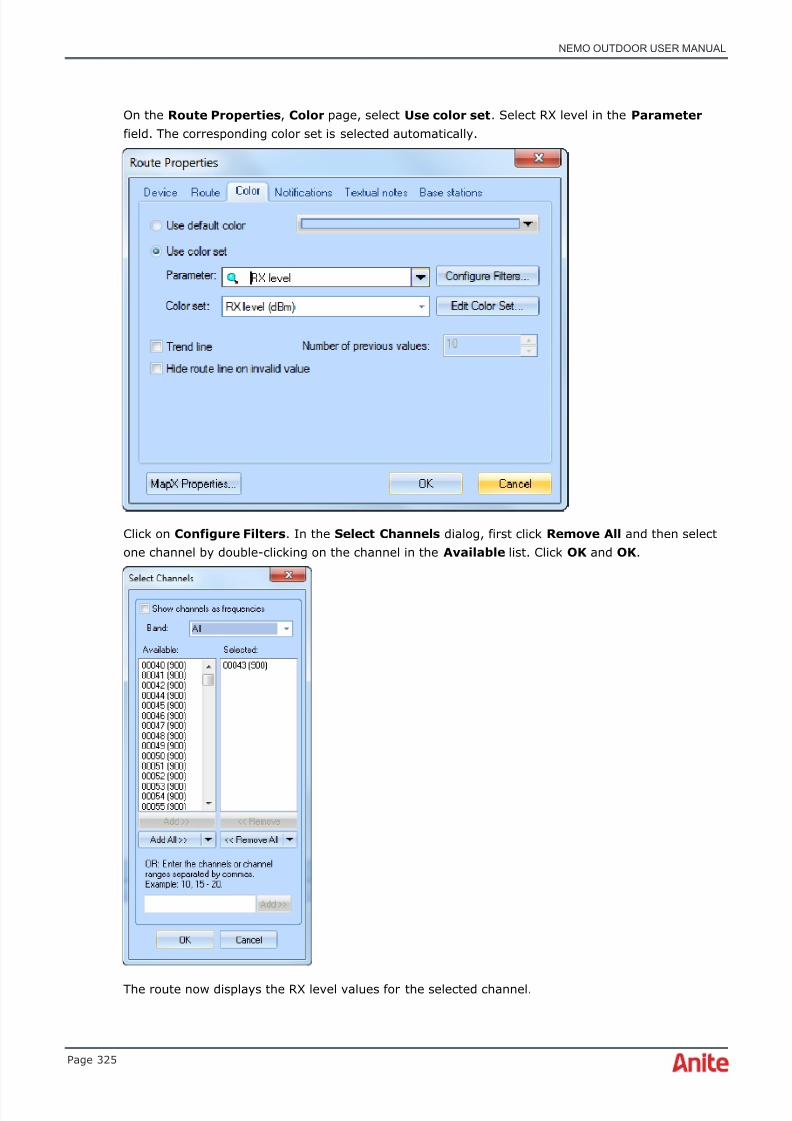
8/16/2019 Nemo Outdoor User Manual
http://slidepdf.com/reader/full/nemo-outdoor-user-manual 325/391
NEMO OUTDOOR USER MANUAL
Page 325
On the Route Properties , Color page, select Use color set . Select RX level in the Parameter field. The corresponding color set is selected automatically.
Click on Configure Filters . In the Select Channels dialog, first click Remove All and then selectone channel by double-clicking on the channel in the Available list. Click OK and OK .
The route now displays the RX level values for the selected channel.

8/16/2019 Nemo Outdoor User Manual
http://slidepdf.com/reader/full/nemo-outdoor-user-manual 326/391
NEMO OUTDOOR USER MANUAL
Page 326
6.31 Export/import settings
It is possible to export and import various settings and measurement lists from and to NemoOutdoor. This function can also be used to send configurations remotely to Nemo Outdoor from an(S)FTP server.
6.31.1 Export settings to file
To export settings to a file, go to File | Export Settings | To File in Nemo Outdoor. Define aname for the .aex file on your PC. The exported settings will be saved in this file.
Next, the Export Settings dialog appears. Select the items you wish to export, and click OK .

8/16/2019 Nemo Outdoor User Manual
http://slidepdf.com/reader/full/nemo-outdoor-user-manual 327/391
NEMO OUTDOOR USER MANUAL
Page 327
The selected items are now saved in the .aex file.
6.31.2 Export settings to FTP server
To export settings to an FTP server, go to File | Export Settings | To FTP Server in NemoOutdoor. Define a name for the .aex file on your PC. The exported settings will be saved in this file.
Click the FTP Options button to define settings for the FTP server. See page 338 for moreinformation on the settings.
Next, the Export Settings dialog appears. Select the items you wish to export, and click OK .

8/16/2019 Nemo Outdoor User Manual
http://slidepdf.com/reader/full/nemo-outdoor-user-manual 328/391
NEMO OUTDOOR USER MANUAL
Page 328
The selected items are now saved in the .aex file and exported to the FTP server. The exportedsettings can now be downloaded from the FTP server to any Nemo Outdoor unit with access to theserver.
6.31.3 Import settings from file
To import settings, select File | Import Settings | From File in Nemo Outdoor. Select the file andclick Open.
Select the settings you wish to import in the Import Settings dialog.

8/16/2019 Nemo Outdoor User Manual
http://slidepdf.com/reader/full/nemo-outdoor-user-manual 329/391
NEMO OUTDOOR USER MANUAL
Page 329
Click OK . The selected settings and files are now saved in Nemo Outdoor and they can be takeninto use.
6.31.4 Import settings from FTP server
To import settings from an FTP server, select File | Import Settings | From FTP Server in NemoOutdoor. If you have not defined any FTP server settings, the list will be empty. When FTP serversettings are defined, a list of exported setting files will appear.
Select the user parameters you wish to import in the Import Settings dialog.

8/16/2019 Nemo Outdoor User Manual
http://slidepdf.com/reader/full/nemo-outdoor-user-manual 330/391
NEMO OUTDOOR USER MANUAL
Page 330
Click OK . The selected settings and files are now saved in Nemo Outdoor and they can be takeninto use.
8/16/2019 Nemo Outdoor User Manual
http://slidepdf.com/reader/full/nemo-outdoor-user-manual 331/391
NEMO OUTDOOR USER MANUAL
Page 331
7 ENDING MEASUREMENTS
The measurement is being recorded when a REC text appears in the upper right corner of the mainwindow. Follow these instructions to stop the measurement.
To end measurements:
1. If you are using a script to perform the measurement, you can either wait until the scriptfile has been executed or interrupt the script either by selecting Measurement | StopScript or by clicking the Stop button on the toolbar.
2. If you are performing measurements manually, the measurement process is terminatedeither by selecting Measurement | Stop or by clicking the Stop button on the toolbar.All the ongoing calls will be stopped and scanning will be terminated. Data transfers will bestopped, PDP context will be deactivated, and GPRS detach will be performed.
3. Nemo Outdoor will display a report window with some call statistics. At this point, you canchoose if you would like to save this file or delete it. You can also start a playback of thisfile.
4. If you wish to exit Nemo Outdoor, select File | Exit or click the cross in the upper rightcorner of the Nemo Outdoor main window.
♦ When carrying out measurements using a script, stopping the measurement is not
recommended while a test call is on. Always wait until the end of the call, then selectMeasurement | Stop Script or click the Stop button to end the measurement. If themeasurement is stopped while the test call is on, it may affect the Quality Survey Reportvalues. The Call Length from the TCH assignment percentage in this report might indicatecalls to be shorter than they actually were.

8/16/2019 Nemo Outdoor User Manual
http://slidepdf.com/reader/full/nemo-outdoor-user-manual 332/391
NEMO OUTDOOR USER MANUAL
Page 332
7.1 Measurement report
The Measurement Report dialog is displayed when recording is stopped. The dialog displays somestatistics from the measurement.
Select the S a v e s t a t i s t i c s t o f i l e option to save the statistics to a separate Excel .csv file. Thefilename is the same as for the actual measurement file and the file is located in the Results folder.
Select the S e n d m e a s u r e m e n t r e s u l t s t o FT P s e r v e r option to send the log files to an FTPserver. See chapter Uploading measurement files to server for more information.
If you do not want this dialog to appear, select the D o n o t s h o w t h i s d ia l o g a g a in option.
Select the Co m p r e s s m e a s u r e m e n t f i l e( s ) option to automatically compress the files below into a
single measurement archive (ZIP file). After the files are compressed, the original files are deleted.• measurement files (.nmf)
• binary files (.nbl)
• packet capture files (.pcap)
• marker files (.mrk)
• indoor map files (.tab and image)
To save the measurement file under another name, click the Rename button and type a new filename in the field that appears. To delete the file without saving, click the Delete button. To exportthe measurement, click the Export button (see Exporting measurements) .

8/16/2019 Nemo Outdoor User Manual
http://slidepdf.com/reader/full/nemo-outdoor-user-manual 333/391
NEMO OUTDOOR USER MANUAL
Page 333
Click the Playback button to playback the measurement file immediately. To save the file, clickSave .
♦ Note that if you press Esc on your computer’s keyboard, or click on the button on thedialog, you will save the measurement file just as if you had clicked on the Save button.
Click the Export button the access the Export Measurements dialog (see Exporting measurements) .
Click the Analyze button to open the measurement file for analysis in Nemo Analyze.
♦ Note that this requires that you have Nemo Analyze installed on the same computerwhere Nemo Outdoor is installed.
In the Export to Nemo Analyze dialog, select a workbook where the data is opened and/or a reporttemplate that is used for creating a report from the data. If you do not select a workbook or a
report, the measurement file is added to the Nemo Analyze database without starting NemoAnalyze. Finally click Export.

8/16/2019 Nemo Outdoor User Manual
http://slidepdf.com/reader/full/nemo-outdoor-user-manual 334/391
NEMO OUTDOOR USER MANUAL
Page 334
8 MEASUREMENT RESULTS
This section guides you on viewing and analyzing the measurement results produced by NemoOutdoor, and explains how measurement files are uploaded to an FTP server.
The measurement process produces one or more output files at a time, depending on whether youhave been using a mobile and a scanner at the same time or just one device at a time. The filename can be user defined but Nemo Outdoor always decides the extension part. If you change thefile name manually, the file name format should be xxxx.1.nmf where the number refers to thedevice number.
8.1 Analyzing measurement results
The measurement results produced by Nemo Outdoor can be viewed and analyzed, for example,with:
• Nemo Outdoor Playback functions
• Nemo Analyze
• Nemo WindCatcher
• Text editor
• Spreadsheet software such as Microsoft® Excel
Mapping software via conversion utilities provided by Anite.
8.2 Playing back measurement files
Playback is a handy tool for making a quick analysis of measurements. You can playback filesanytime and anywhere immediately after the measurement has been finished or later on.
8.2.1 Selecting playback files
When you open a file for playback, Nemo Outdoor will deactivate all connected devices. NemoOutdoor will ask if you would like to save the current device. If you answer Yes , Nemo Outdoor willsave the current configuration and reactivate the devices that you had connected before theplayback when you close the playback file(s).

8/16/2019 Nemo Outdoor User Manual
http://slidepdf.com/reader/full/nemo-outdoor-user-manual 335/391
NEMO OUTDOOR USER MANUAL
Page 335
To open files for playback, select File Open Measurement . This will open up the followingdialog.
In the dialog, you can look for a file by clicking the … button. The File Header box displays themeasurement file header. If you have selected a multi measurement, you can remove some of the
files from playback.
8.2.2 During playback
The Playback commands can be executed with a set of toolbar buttons. The same commands can befound in the Playback menu.
The Play button starts the playback.
The Pause button pauses the playback.
The Stop button stops the playback.
The status bar at the bottom of the main window displays the progress of the playback; that is, thestarting, ending, and current time. There is also a time slider which you can use to jump intocertain points in the measurement.
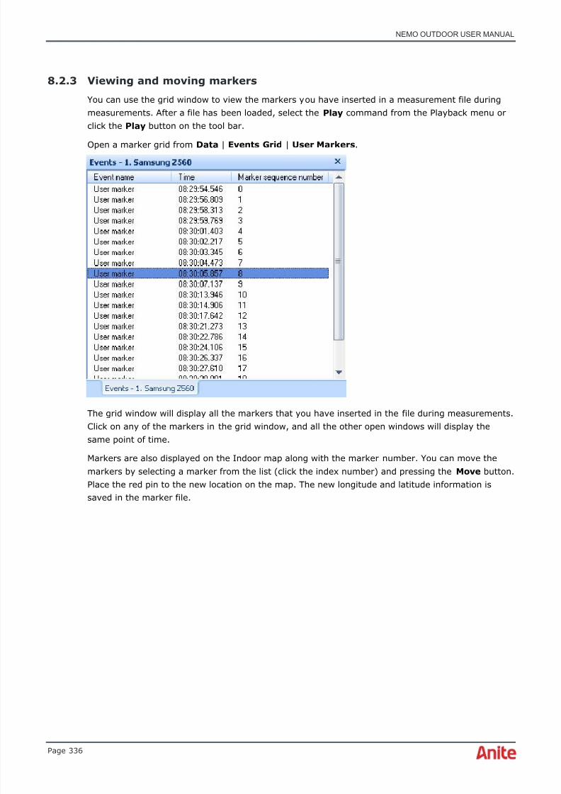
8/16/2019 Nemo Outdoor User Manual
http://slidepdf.com/reader/full/nemo-outdoor-user-manual 336/391
NEMO OUTDOOR USER MANUAL
Page 336
8.2.3 Viewing and moving markers
You can use the grid window to view the markers you have inserted in a measurement file duringmeasurements. After a file has been loaded, select the Play command from the Playback menu orclick the Play button on the tool bar.
Open a marker grid from Data | Events Grid | User Markers .
The grid window will display all the markers that you have inserted in the file during measurements.Click on any of the markers in the grid window, and all the other open windows will display thesame point of time.
Markers are also displayed on the Indoor map along with the marker number. You can move themarkers by selecting a marker from the list (click the index number) and pressing the Move button.Place the red pin to the new location on the map. The new longitude and latitude information issaved in the marker file.

8/16/2019 Nemo Outdoor User Manual
http://slidepdf.com/reader/full/nemo-outdoor-user-manual 337/391
NEMO OUTDOOR USER MANUAL
Page 337
8.2.4 Closing playback files
After playback, you need to close the playback file. Select File | Close Measurement . If you savedthe current device configuration when you started the playback, Nemo Outdoor will ask if you wouldlike to load the same device(s).
8.3 Uploading measurement files to server
You can upload measurement files from Nemo Outdoor to an FTP server or to Nemo Xynergydatabase when a measurement is stopped, or at any later point via the Nemo Outdoor userinterface. Note that it is recommended to stop all measurements before uploading files.
Select File | Send Measurement to Server . First select the server type, FTP or Xynergy from thebottom left corner of the dialog and then select the measurement files.

8/16/2019 Nemo Outdoor User Manual
http://slidepdf.com/reader/full/nemo-outdoor-user-manual 338/391
NEMO OUTDOOR USER MANUAL
Page 338
Click the Options button to define settings for the selected server (FTP or Nemo Xynergy ) . Afterconfiguring the settings, click OK . The measurement file(s) are sent to the server.
If you upload files on an HTTPS server, the URL from which the file can be loaded is displayed foreach uploaded file. URLs can be easily copied and distributed e.g. by email.
8.3.1 FTP Options
Define the server address , username , and password and the name of the Remote folder , i.e.folder in which the measurement files are sent on the server.
Select the Use SFTP protocol option to send the measurement files using SFTP protocol.
Select the Use secure protocol option to send the measurement files using HTTPS protocol.
Select the Use passive mode option to send the measurement files using passive mode.

8/16/2019 Nemo Outdoor User Manual
http://slidepdf.com/reader/full/nemo-outdoor-user-manual 339/391
NEMO OUTDOOR USER MANUAL
Page 339
When the Move local files to “Sent” folder after upload option is selected, the measurementfiles are moved to the Sent folder in the C:\Nemo Tools directory on your computer after thetransfer. You can also change this default destination in User Interface Properties | Paths |Measurements .
The file transfer can be performed using a default Internet connection, via a user-selected dataconnection, or via mobile broadband.
When you select the Use a Proxy Server option, the Proxy address , Username and Password fields will become active.
8.3.2 Nemo Xynergy Options
Define the username , password , and URI and click the Refresh button. Nemo Outdoor willconnect with the Nemo Xynergy server. After the connection has been established, you will be ableto define the project type (acceptance, optimization, benchmarking), region , market , cluster ,and project . You can also add new clusters and projects.
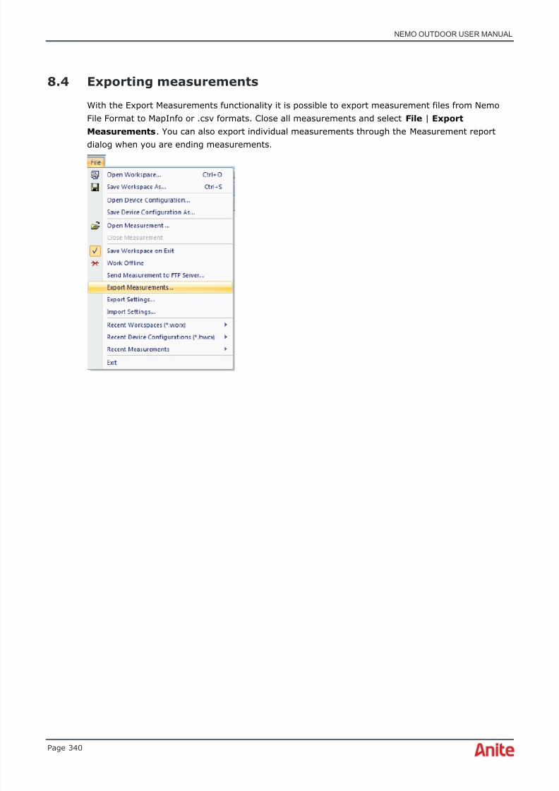
8/16/2019 Nemo Outdoor User Manual
http://slidepdf.com/reader/full/nemo-outdoor-user-manual 340/391
NEMO OUTDOOR USER MANUAL
Page 340
8.4 Exporting measurements
With the Export Measurements functionality it is possible to export measurement files from NemoFile Format to MapInfo or .csv formats. Close all measurements and select File | ExportMeasurements . You can also export individual measurements through the Measurement reportdialog when you are ending measurements.

8/16/2019 Nemo Outdoor User Manual
http://slidepdf.com/reader/full/nemo-outdoor-user-manual 341/391
NEMO OUTDOOR USER MANUAL
Page 341
The Export Measurements dialog is opened.
Template contains a predefined set of parameters and parameter rules for export. To create a newtemplate, select New in the Template field and type a name for the template. Then select theparameters that will be exported and define parameter rules. When you export the parameters, thesettings are saved. The saved template will be available in the Template field the next time youopen the Export Measurements dialog.
With the Add Measurement and Add Folder buttons you can add individual measurement files orentire folders containing measurement files to be exported.
Export format defines the format in which the files are stored. The options are MapInfo TAB fileand CSV file.
Number of values per parameter defines the maximum number of values exported forparameters that can have multiple values.
Export interval defines at what rate (in seconds or meters) parameter values are sampled fromthe measurement data for export. If you select all, all data is exported.
By default, multiple values of the same parameter are exported in a single column. To create a
separate column for each value, select the Separate values to columns option.

8/16/2019 Nemo Outdoor User Manual
http://slidepdf.com/reader/full/nemo-outdoor-user-manual 342/391

8/16/2019 Nemo Outdoor User Manual
http://slidepdf.com/reader/full/nemo-outdoor-user-manual 343/391
NEMO OUTDOOR USER MANUAL
Page 343
Select a parameter from the field in the middle. Then define the condition and value for theparameter and click Add to List . You can define as many rules as you wish. Finally click OK .
When you have selected all parameters to be exported, click OK .

8/16/2019 Nemo Outdoor User Manual
http://slidepdf.com/reader/full/nemo-outdoor-user-manual 344/391
NEMO OUTDOOR USER MANUAL
Page 344
9 USER INTERFACE
This section presents the Nemo Outdoor user interface. You will find general descriptions on all thecommands and windows. The functions and dialogs related to the commands are described in detailin the following sections.
The Nemo Outdoor user interface is compatible with common Windows® standards. If you are notfamiliar with these standards, refer to your Microsoft® Windows® Documentation.
9.1 View groups
View Groups is a function that allows you to organize measurement windows into different tabs foreasier viewing. This is especially useful if you have several graphs and maps open at the same timeand you have to overlap them to fit them all in the Nemo Outdoor main window. Now you cancreate view groups and organize the measurement windows into several groups. Each view groupappears at the bottom of the main window as a tab that you can view by clicking the tab.
When you start Nemo Outdoor for the first time, you will have one default view group. To renamethe default view group, right-click on the tab and select Rename .
Enter a name for the view group and click OK .
To create a new view group, right-click on the empty area next to the existing view groups, andselect Create New . Enter a name for the view group and click OK . The new view group appears asanother tab.
To organize measurement windows into the view groups, open a view group, for example, Maps,and open the windows that you would like to have in this particular view group. Then go to anotherview group by clicking on the respective tab, for example, Graphs and open measurement windows
there. The windows are automatically saved in the view groups and will be opened the next timeyou start Nemo Outdoor.

8/16/2019 Nemo Outdoor User Manual
http://slidepdf.com/reader/full/nemo-outdoor-user-manual 345/391
NEMO OUTDOOR USER MANUAL
Page 345
To copy the contents of an existing view group to a new view group, right-click on the view grouplabel and select Copy to New View Group . Type a name for the new view group and select thedevice for which the data is displayed.
If you need to change the device for which the views in a particular view group are displaying data,right-click the view group label and select Select Device . Select the device from the list. All theviews in the view group will be updated to display data from the selected device.
9.2 Menu bar
The menu bar contains all Nemo Outdoor commands. The commands are arranged in menus. Somecommands execute their respective operations immediately, while others will first display a dialogwith options for you to select from. A command ending in three dots (…) will open a dialog. Notethat you can use shortcut keys to carry out some of the commands. The shortcut keys arepresented on the menus next to the menu commands.
9.3 Toolbar
You can use the toolbar with the mouse for quick access to frequently used commands. In the Viewmenu, you can choose to hide the toolbar; this will bring more space to the other objects in themain window.
The Nemo Outdoor toolbar comprises of a set of buttons that allow you to perform common tasksquickly. For example, to start the measurement, just click the Start Recording button on thetoolbar. See chapter Toolbar buttons for more information on the Nemo Outdoor toolbar buttons.
9.4 Status bar
The status bar at the bottom of the Nemo Outdoor window gives you variable informationdepending on the operations you are performing. For example, when you are pointing to a toolbarbutton with the mouse (without clicking), the status bar will show a description of thecorresponding function. You can also see a brief description of the same function in a help box thatappears next to the button when you hold the mouse over the button long enough. There is also atime slider which you can use to jump into certain points in the measurement.
In the View menu, you can select to hide the status bar; this will bring more space to the otherobjects in the main window.
9.5 Nemo Outdoor menusThe menus in the Nemo Outdoor software are introduced next.
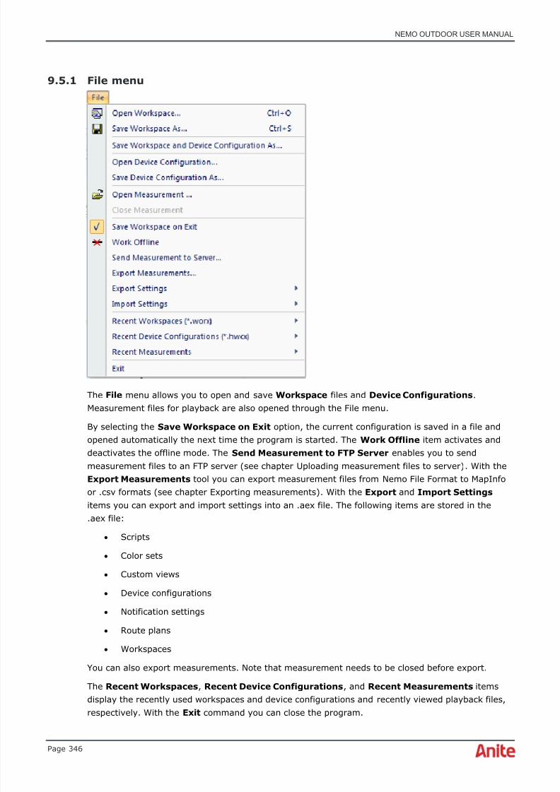
8/16/2019 Nemo Outdoor User Manual
http://slidepdf.com/reader/full/nemo-outdoor-user-manual 346/391
NEMO OUTDOOR USER MANUAL
Page 346
9.5.1 File menu
The File menu allows you to open and save Workspace files and Device Configurations .Measurement files for playback are also opened through the File menu.
By selecting the Save Workspace on Exit option, the current configuration is saved in a file andopened automatically the next time the program is started. The Work Offline item activates anddeactivates the offline mode. The Send Measurement to FTP Server enables you to sendmeasurement files to an FTP server (see chapter Uploading measurement files to server) . With theExport Measurements tool you can export measurement files from Nemo File Format to MapInfoor .csv formats (see chapter Exporting measurements) . With the Export and Import Settings items you can export and import settings into an .aex file. The following items are stored in the.aex file:
• Scripts
• Color sets
• Custom views
• Device configurations
• Notification settings
• Route plans
• Workspaces
You can also export measurements. Note that measurement needs to be closed before export.
The Recent Workspaces , Recent Device Configurations , and Recent Measurements itemsdisplay the recently used workspaces and device configurations and recently viewed playback files,respectively. With the Exit command you can close the program.
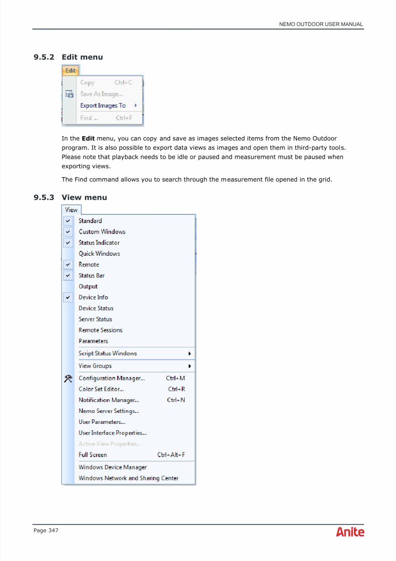
8/16/2019 Nemo Outdoor User Manual
http://slidepdf.com/reader/full/nemo-outdoor-user-manual 347/391
NEMO OUTDOOR USER MANUAL
Page 347
9.5.2 Edit menu
In the Edit menu, you can copy and save as images selected items from the Nemo Outdoorprogram. It is also possible to export data views as images and open them in third-party tools.Please note that playback needs to be idle or paused and measurement must be paused whenexporting views.
The Find command allows you to search through the measurement file opened in the grid.
9.5.3 View menu

8/16/2019 Nemo Outdoor User Manual
http://slidepdf.com/reader/full/nemo-outdoor-user-manual 348/391
NEMO OUTDOOR USER MANUAL
Page 348
In the View menu, you can select, hide and display items of the main window, such as thestandard toolbar, custom window toolbar, status indicator, output, and device status, those youwish to see on the screen. Through quick windows you have easy access to custom windows definedby the user. You can also access the Configuration Manager, Color Set Editor, NotificationManager, User Parameters and the User Interface Properties dialogs. Through the ViewGroups item you can create new view groups or switch between existing View groups. The ActiveView Properties will open a properties dialog for the currently active window.
9.5.4 Measurement menu
Through the Measurement menu, you can control the measurement process and add, autodetect,and remove devices.
The Start Scripts command starts and stops a user-defined script file. These same commands canbe executed by clicking the Start/Stop Scripts button in the toolbar. In the Script Editor youcan edit script files. With the Start Measurement List item you can edit and run Measurementlists. You can also add markers and textual notes in the measurement file. The Clear Buffers command will empty the event history buffer. This does not affect the measurement file.
Measurement Servers and Nemo Invex Maintenance Tool items apply only to Nemo Invex.
Through the All Devices item you can control several devices at once. For example, you can makea voice call or send an SMS with all test mobiles connected to Nemo Outdoor.
Below All Devices are listed individually all measurement devices connected to the system. Throughthese items you can control and configure the individual test terminals.

8/16/2019 Nemo Outdoor User Manual
http://slidepdf.com/reader/full/nemo-outdoor-user-manual 349/391
NEMO OUTDOOR USER MANUAL
Page 349
Measurement Properties – General, Measurement Properties – Measurement, MeasurementProperties – Frequency scanning with mobiles , Measurement Properties – Pilot scanning withmobiles, and Measurement Properties - Script dialogs can be accessed through this menu. Byselecting the Reset command, you can reset the Devices window, for example, if you want toreconnect and activate a device after disconnecting it.
The menu also offers access to various actions that can be performed during manualmeasurements. If you are using scripts to run measurements, you will not need these commands.
♦ Please note that the menu displays only those functions that are supported by the device.
9.5.5 Remote menu
Through the Remote menu you can activate the Remote mode, initiate a maintenance session, andcancel all pending remote sessions.
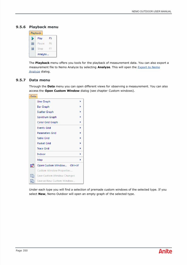
8/16/2019 Nemo Outdoor User Manual
http://slidepdf.com/reader/full/nemo-outdoor-user-manual 350/391
NEMO OUTDOOR USER MANUAL
Page 350
9.5.6 Playback menu
The Playback menu offers you tools for the playback of measurement data. You can also export ameasurement file to Nemo Analyze by selecting Analyze . This will open the Export to NemoAnalyze dialog.
9.5.7 Data menu
Through the Data menu you can open different views for observing a measurement. You can alsoaccess the Open Custom Window dialog (see chapter Custom windows) .
Under each type you will find a selection of premade custom windows of the selected type. If youselect New , Nemo Outdoor will open an empty graph of the selected type.

8/16/2019 Nemo Outdoor User Manual
http://slidepdf.com/reader/full/nemo-outdoor-user-manual 351/391
NEMO OUTDOOR USER MANUAL
Page 351
The Grid items offer a selection of grid types. Events grids list, by default, all measurement eventsbut the user can configure the view so that only events that are of special interest are displayed.Parameters grids display selected network parameters. Statistics grids list various statistics, suchas, the number of PDP context activation attempts, successes, and failures from the measurement.Messages grids are used for observing layer 2 and 3, RLC/MAC, and LLC messages. Table gridsprovide an easy way of simultaneously displaying the same parameter values for multiple instances.For example, the neighbor list of a serving cell can be displayed in a table grid so that each rowrepresents one neighbor and each column represents a parameter value (e.g., system, carrier,scrambling code, etc.). The Packet Decoder Grid offers a chance to display and decode packetcapture files in playback mode.
The Indoor item opens a floorplan (see chapter Viewing indoor maps) . The Map item opens a mapwindow (see chapter Viewing maps) .
The Save as Custom Window… item offers a quick way to save your own custom windows. Thecustom windows are presented in chapter Custom windows.
The Save Custom Window Changes option saves changes to custom windows. For example, ifyou resize the windows, Nemo Outdoor will open the window in the same size the next time youstart the program.
9.5.8 Window menu
The Window menu provides you with a list of all open windows on the main window. You canswitch the focus between these windows and arrange them with the Cascade , Tile Horizontally,Tile Vertically , and Arrange Icons commands. With the Close All command you can close allwindows at once. The active window is marked with a check mark .
9.5.9 Help menu
The Help menu offers you quick access to all the most important help topics, the shortcut guide,and the Nemo File Format document. By selecting the License Information item, you can checkthe current license status for your Nemo Outdoor version. From the About dialog you can alsoreceive further information on the Nemo Outdoor application, including the contact information andthe application version number.
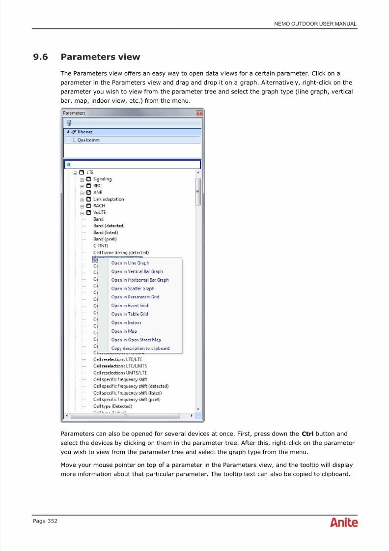
8/16/2019 Nemo Outdoor User Manual
http://slidepdf.com/reader/full/nemo-outdoor-user-manual 352/391
NEMO OUTDOOR USER MANUAL
Page 352
9.6 Parameters view
The Parameters view offers an easy way to open data views for a certain parameter. Click on aparameter in the Parameters view and drag and drop it on a graph. Alternatively, right-click on theparameter you wish to view from the parameter tree and select the graph type (line graph, verticalbar, map, indoor view, etc.) from the menu.
Parameters can also be opened for several devices at once. First, press down the Ctrl button andselect the devices by clicking on them in the parameter tree. After this, right-click on the parameteryou wish to view from the parameter tree and select the graph type from the menu.
Move your mouse pointer on top of a parameter in the Parameters view, and the tooltip will displaymore information about that particular parameter. The tooltip text can also be copied to clipboard.

8/16/2019 Nemo Outdoor User Manual
http://slidepdf.com/reader/full/nemo-outdoor-user-manual 353/391
NEMO OUTDOOR USER MANUAL
Page 353
9.6.1 Parameters view search functionality
A user-specified search string can be used to search parameters, parameter short names andpossible alias names.
In addition, the string matching supports multiple search substrings separated by spaces i.e. HSDPABLER search string matches, for example, HSDPA MAC-hs BLER and HSDPA HARQ process BLER.
9.7 Customizing menus and toolbars
Nemo Outdoor menus and toolbars are fully customizable. To edit the contents of menus, to addnew menus, or edit the toolbars, right-click on the menu bar or toolbar at the top of the mainwindow and select Customize .
In the Toolbars page hide and display the default toolbars by clearing and selecting thecorresponding options. Click the New button to create a new toolbar. In the New Toolbar dialog,type a name for the new toolbar and click OK .

8/16/2019 Nemo Outdoor User Manual
http://slidepdf.com/reader/full/nemo-outdoor-user-manual 354/391
NEMO OUTDOOR USER MANUAL
Page 354
The new toolbar is added to the Customize dialog. Delete the toolbar by selecting it and clickingthe Delete button.
In the Commands page you will find all available commands sorted under categories. Dragcommands from the list to a toolbar or menu.

8/16/2019 Nemo Outdoor User Manual
http://slidepdf.com/reader/full/nemo-outdoor-user-manual 355/391

8/16/2019 Nemo Outdoor User Manual
http://slidepdf.com/reader/full/nemo-outdoor-user-manual 356/391
NEMO OUTDOOR USER MANUAL
Page 356
In the Options page you can further personalize the appearance of toolbars and menus. Forexample, you can activate large icons for toolbars for easier viewing or change the menuanimations.
You can also change the icon for each toolbar button. Open the Customize dialog, right-click on abutton, and select Change Button Image .
9.8 Nemo Outdoor windows
The windows in Nemo Outdoor are highly user configurable. Different network parameters andevents can be viewed as line graphs, bars, and dots. To make the measuring process easier forfirst-time users, Nemo Outdoor offers some ready-made custom windows that include someessential windows for specific types of measuring. The users are also able to make their owncustom windows and save them for later use.

8/16/2019 Nemo Outdoor User Manual
http://slidepdf.com/reader/full/nemo-outdoor-user-manual 357/391
NEMO OUTDOOR USER MANUAL
Page 357
9.8.1 Custom windows
Nemo Outdoor offers a selection of premade graphs and grids which can be quickly accessedthrough the Data menu or the Custom window tool bar if selected in the View menu. They are alsoaccessible through the parameter tree. The custom windows are grouped under the corresponding
graph and grid types. You can also browse for the existing custom windows through the OpenCustom Window dialog ( Data | Open Custom Window ).
You can view the existing custom windows sorted by type (graph, grid, map, indoor view) or bytechnology (AMPS, CDMA, GSM, UMTS, etc.). Select the custom window you would like to openfrom the table on the right and click Open .
You can also save your own custom windows. When you have set up a graph view that you wouldlike to use later on, activate the window that you would like to save and select Data | Save as Custom Window . Nemo Outdoor will ask you to type a name for the new custom window. Afterclicking OK , the window is added to the custom windows list. If you want to remove some customwindows, select the custom window that you want to remove and click the Delete button.
The Quick Windows bar (go to View , and select Quick Windows) inNemo Outdoor main window offers quick access to custom windows. Click on one of the quick
windows, and select a custom window from the list. Click OK . The next time you click on the samequick window button, that selected custom window will appear.

8/16/2019 Nemo Outdoor User Manual
http://slidepdf.com/reader/full/nemo-outdoor-user-manual 358/391
NEMO OUTDOOR USER MANUAL
Page 358
9.8.2 Devices view

8/16/2019 Nemo Outdoor User Manual
http://slidepdf.com/reader/full/nemo-outdoor-user-manual 359/391
NEMO OUTDOOR USER MANUAL
Page 359
The Devices view offers easy access to the most common commands and configuration dialogs.The view displays all devices connected to Nemo Outdoor and the device-specific commands. Bydouble-clicking the various items in the view, you can access the related configuration dialogs. Forexample, double-click the FTP item to access the FTP Transfer Properties dialog.
It is also possible to select multiple devices (Ctrl+left-click) and define settings that will be appliedto all selected devices. For example, if the same APN is used with several devices, you can selectthe devices and define the APN for all devices at one go. When you have selected multiple devices,you can only edit settings that are supported by all the selected devices.
From the Supported Data Protocols list, select the data protocol (FTP, SMTP, TCP/UDP, etc.)used in the measurements.
Measurement servers button opens the MeasurementServers dialog (see Nemo Invex device set-up) where youcan connect to Nemo Invex servers. Note that this buttonis activated only if your Nemo Outdoor license
includes the Nemo Invex option.
Add or remove devices button opens a menu where youcan choose to add a new device or remove the selecteddevice.
Measurement control button offers access to somecommands that are supported by the selected device, suchas, start/stop voice call, GPRS attach/detach, SMS/MMSmessage sending.
Measurement settings button offers access toconfiguration and properties dialogs. The selection is device-
specific.
Device connection settings button opens the DeviceConfiguration dialog (see Devices) .
Device measurement settings button opens theMeasurement Properties – Measurement page for theselected device.
Device notification settings button opens theMeasurement Properties - Notifications page (seeNotifications) for the selected device.
Device script settings button opens the MeasurementProperties - Script page for the selected device.
Group devices by type/server button organizes thedevices in the view.
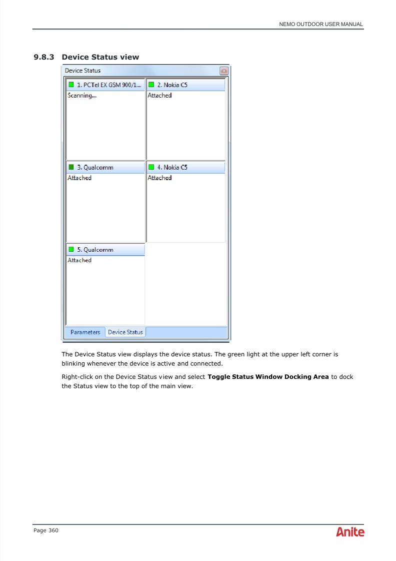
8/16/2019 Nemo Outdoor User Manual
http://slidepdf.com/reader/full/nemo-outdoor-user-manual 360/391
NEMO OUTDOOR USER MANUAL
Page 360
9.8.3 Device Status view
The Device Status view displays the device status. The green light at the upper left corner isblinking whenever the device is active and connected.
Right-click on the Device Status view and select Toggle Status Window Docking Area to dockthe Status view to the top of the main view.

8/16/2019 Nemo Outdoor User Manual
http://slidepdf.com/reader/full/nemo-outdoor-user-manual 361/391
NEMO OUTDOOR USER MANUAL
Page 361
Right-click on the Device Status view and select Reorder Devices to change the order of thedevices in the Device Status and Devices views. Drag and drop the devices in the correct order andfinally click OK .
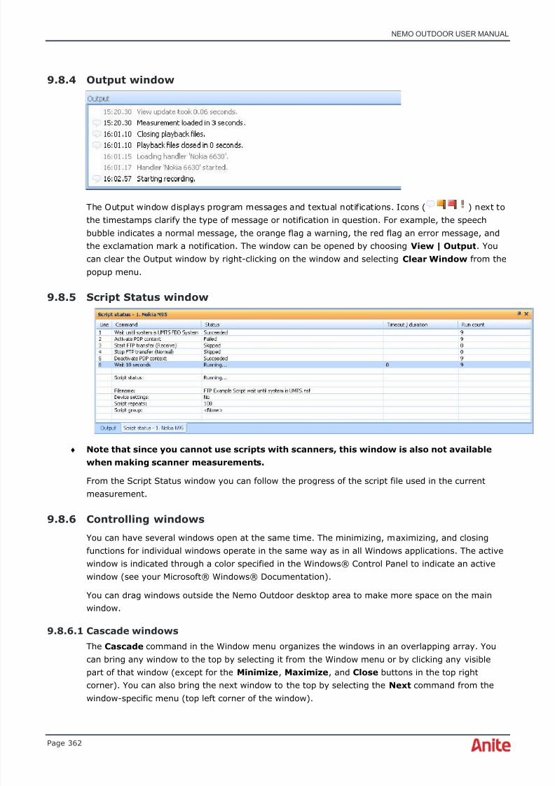
8/16/2019 Nemo Outdoor User Manual
http://slidepdf.com/reader/full/nemo-outdoor-user-manual 362/391
NEMO OUTDOOR USER MANUAL
Page 362
9.8.4 Output window
The Output window displays program messages and textual notifications. Icons ( ) next tothe timestamps clarify the type of message or notification in question. For example, the speechbubble indicates a normal message, the orange flag a warning, the red flag an error message, andthe exclamation mark a notification. The window can be opened by choosing View | Output . Youcan clear the Output window by right-clicking on the window and selecting Clear Window from the
popup menu.
9.8.5 Script Status window
♦ Note that since you cannot use scripts with scanners, this window is also not availablewhen making scanner measurements.
From the Script Status window you can follow the progress of the script file used in the currentmeasurement.
9.8.6 Controlling windows
You can have several windows open at the same time. The minimizing, maximizing, and closing
functions for individual windows operate in the same way as in all Windows applications. The activewindow is indicated through a color specified in the Windows® Control Panel to indicate an activewindow (see your Microsoft® Windows® Documentation).
You can drag windows outside the Nemo Outdoor desktop area to make more space on the mainwindow.
9.8.6.1 Cascade windows
The Cascade command in the Window menu organizes the windows in an overlapping array. Youcan bring any window to the top by selecting it from the Window menu or by clicking any visiblepart of that window (except for the Minimize , Maximize , and Close buttons in the top right
corner). You can also bring the next window to the top by selecting the Next command from thewindow-specific menu (top left corner of the window).

8/16/2019 Nemo Outdoor User Manual
http://slidepdf.com/reader/full/nemo-outdoor-user-manual 363/391
NEMO OUTDOOR USER MANUAL
Page 363
9.8.6.2 Tile windows
The Tile command in the Window menu organizes the windows side by side, filling the whole spaceso that all windows are visible at the same time. The windows can be tiled horizontally or vertically.
9.8.6.3 Arrange icons
The windows that have been minimized to icons can be arranged evenly in a row at the bottom ofthe main window, starting from the left side. To do this, select the Arrange Icons command in theWindow menu.
9.8.6.4 Close all
The Close All command in the Window menu can be used to close all measurement windows in theNemo Outdoor main window.
9.8.6.5 Saving window settings
If you wish to retain the same settings on your main window the next time you use Nemo Outdoor,
activate the Save Workspace on Exit command in the File menu. Clicking the command will resulton a check mark ; the second click will remove the mark.
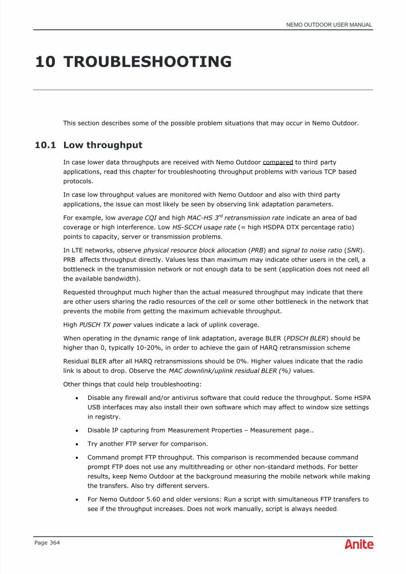
8/16/2019 Nemo Outdoor User Manual
http://slidepdf.com/reader/full/nemo-outdoor-user-manual 364/391
NEMO OUTDOOR USER MANUAL
Page 364
10 TROUBLESHOOTING
This section describes some of the possible problem situations that may occur in Nemo Outdoor.
10.1 Low throughput
In case lower data throughputs are received with Nemo Outdoor compared to third partyapplications, read this chapter for troubleshooting throughput problems with various TCP basedprotocols.
In case low throughput values are monitored with Nemo Outdoor and also with third partyapplications, the issue can most likely be seen by observing link adaptation parameters.
For example, low average CQI and high MAC-HS 3 rd retransmission rate indicate an area of badcoverage or high interference. Low HS-SCCH usage rate (= high HSDPA DTX percentage ratio)points to capacity, server or transmission problems.
In LTE networks, observe physical resource block allocation ( PRB ) and signal to noise ratio ( SNR ).PRB affects throughput directly. Values less than maximum may indicate other users in the cell, abottleneck in the transmission network or not enough data to be sent (application does not need allthe available bandwidth).
Requested throughput much higher than the actual measured throughput may indicate that there
are other users sharing the radio resources of the cell or some other bottleneck in the network thatprevents the mobile from getting the maximum achievable throughput.
High PUSCH TX power values indicate a lack of uplink coverage.
When operating in the dynamic range of link adaptation, average BLER ( PDSCH BLER ) should behigher than 0, typically 10-20%, in order to achieve the gain of HARQ retransmission scheme
Residual BLER after all HARQ retransmissions should be 0%. Higher values indicate that the radiolink is about to drop. Observe the MAC downlink/uplink residual BLER (%) values.
Other things that could help troubleshooting:
• Disable any firewall and/or antivirus software that could reduce the throughput. Some HSPAUSB interfaces may also install their own software which may affect to window size settingsin registry.
• Disable IP capturing from Measurement Properties – Measurement page..
• Try another FTP server for comparison.
• Command prompt FTP throughput. This comparison is recommended because commandprompt FTP does not use any multithreading or other non-standard methods. For betterresults, keep Nemo Outdoor at the background measuring the mobile network while makingthe transfers. Also try different servers.
• For Nemo Outdoor 5.60 and older versions: Run a script with simultaneous FTP transfers tosee if the throughput increases. Does not work manually, script is always needed.
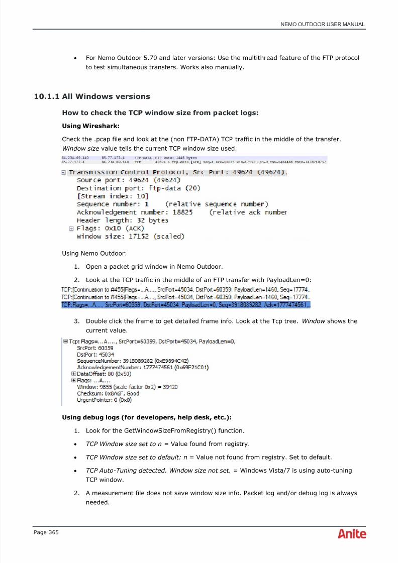
8/16/2019 Nemo Outdoor User Manual
http://slidepdf.com/reader/full/nemo-outdoor-user-manual 365/391
NEMO OUTDOOR USER MANUAL
Page 365
• For Nemo Outdoor 5.70 and later versions: Use the multithread feature of the FTP protocolto test simultaneous transfers. Works also manually.
10.1.1 All Windows versionsHow to check the TCP window size from packet logs:
Using Wireshark:
Check the .pcap file and look at the (non FTP-DATA) TCP traffic in the middle of the transfer.Window size value tells the current TCP window size used.
Using Nemo Outdoor:
1. Open a packet grid window in Nemo Outdoor.
2. Look at the TCP traffic in the middle of an FTP transfer with PayloadLen=0:
3. Double click the frame to get detailed frame info. Look at the Tcp tree. Window shows thecurrent value.
Using debug logs (for developers, help desk, etc.):
1. Look for the GetWindowSizeFromRegistry() function.
• TCP Window size set to n = Value found from registry.
• TCP Window size set to default: n = Value not found from registry. Set to default.
• TCP Auto-Tuning detected. Window size not set. = Windows Vista/7 is using auto-tuningTCP window.
2. A measurement file does not save window size info. Packet log and/or debug log is alwaysneeded.
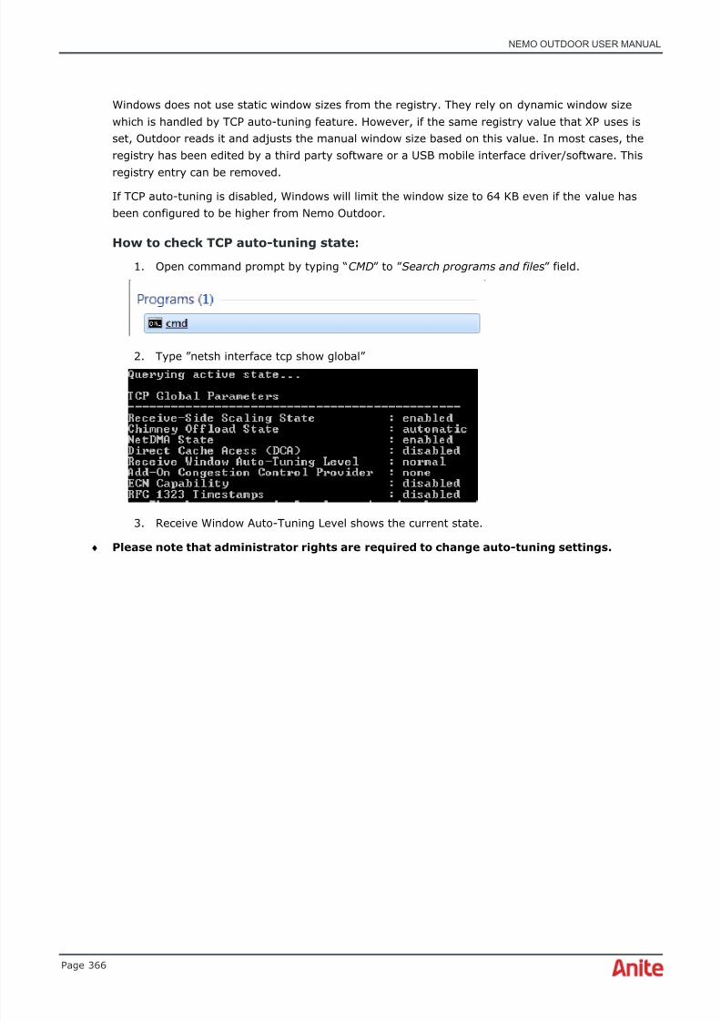
8/16/2019 Nemo Outdoor User Manual
http://slidepdf.com/reader/full/nemo-outdoor-user-manual 366/391
NEMO OUTDOOR USER MANUAL
Page 366
Windows does not use static window sizes from the registry. They rely on dynamic window sizewhich is handled by TCP auto-tuning feature. However, if the same registry value that XP uses isset, Outdoor reads it and adjusts the manual window size based on this value. In most cases, theregistry has been edited by a third party software or a USB mobile interface driver/software. Thisregistry entry can be removed.
If TCP auto-tuning is disabled, Windows will limit the window size to 64 KB even if the value hasbeen configured to be higher from Nemo Outdoor.
How to check TCP auto-tuning state:
1. Open command prompt by typing “ CMD” to ” Search programs and files ” field.
2. Type ”netsh interface tcp show global”
3. Receive Window Auto-Tuning Level shows the current state.
♦ Please note that administrator rights are required to change auto-tuning settings.

8/16/2019 Nemo Outdoor User Manual
http://slidepdf.com/reader/full/nemo-outdoor-user-manual 367/391

8/16/2019 Nemo Outdoor User Manual
http://slidepdf.com/reader/full/nemo-outdoor-user-manual 368/391
NEMO OUTDOOR USER MANUAL
Page 368
10.2 Device Status view
The Device Status view displays the device status.
If a green light is blinking, it means that the device is properly connected to Nemo Outdoor and isfunctioning normally.
If a red light is blinking, it means that the device has been disconnected. Connect the device, right-click on the device in the Devices view and select Reset .
10.3 Cannot add devices
If the Add button is deactivated in the Configuration Manager window when you start NemoOutdoor, your version of Nemo Outdoor is an unlicensed evaluation version. Please, see chapterLicensing for more information.
If the HASP USB key is plugged in and the Add button is deactivated, check that recording is noton. Also, playback should be stopped and playback files closed ( File | Close Measurement ).
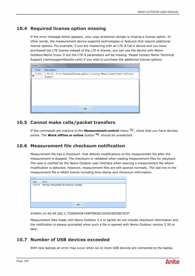
8/16/2019 Nemo Outdoor User Manual
http://slidepdf.com/reader/full/nemo-outdoor-user-manual 369/391
NEMO OUTDOOR USER MANUAL
Page 369
10.4 Required license option missing
If the error message below appears, your copy protection dongle is missing a license option. Inother words, the measurement device supports technologies or features that require additionallicense options. For example, if you are measuring with an LTE-A Cat 6 device and you havepurchased the LTE license instead of the LTE-A license, you can use the device with NemoOutdoor/Nemo Invex II but the LTE-A parameters will be missing. Please contact Nemo TechnicalSupport ([email protected]) if you wish to purchase the additional license options.
10.5 Cannot make calls/packet transfers
If the commands are inactive in the Measurement control menu , check that you have devicesonline. The Work offline or online button should be unselected.
10.6 Measurement file checksum notification
Measurement file has a checksum that detects modifications to the measurement file after themeasurement is stopped. The checksum is validated when loading measurement files for playback.The user is notified by the Nemo Outdoor user interface when opening a measurement file wheremodification is detected. However, measurement files are still opened normally. The last line in themeasurement file is HASH events including time stamp and checksum information.
#HASH,14:46:49.262,1,"0360D938749FFE82B15545D3E55B75C0"
Measurement files made with Nemo Outdoor 5.4 or earlier do not include checksum information andthe notification is always prompted when such a file is opened with Nemo Outdoor version 5.50 orlater.
10.7 Number of USB devices exceededWith new laptops an error may occur when six or more USB devices are connected to the laptop.

8/16/2019 Nemo Outdoor User Manual
http://slidepdf.com/reader/full/nemo-outdoor-user-manual 370/391
NEMO OUTDOOR USER MANUAL
Page 370
The current of the USB hub used by the laptop exceeds the max. value per device and the driverblocks additional devices. This applies especially to the USB 3.0 host controllers based on the Intelchipset.
The issue can be fixed by uninstalling the Intel USB 3.0 host controller driver.
♦ Note that especially with Lenovo computers, the driver is automatically installedwith system updates. Automated updates should be disabled.
Thelinked imagecannotbedisplayed. Thefilemayhavebeen moved, renamed, ordeleted. Verifythatthelinkpointsto thecorrectfileand location.
Thelinked imagecannotbedisplayed. Thefilemayhavebeen moved, renamed, ordeleted. Verifythatthelinkpointsto thecorrectfileand location.

8/16/2019 Nemo Outdoor User Manual
http://slidepdf.com/reader/full/nemo-outdoor-user-manual 371/391
NEMO OUTDOOR USER MANUAL
Page 371
11 NEMO OUTDOOR BUTTONS
11.1 Toolbar buttons
These are the buttons available in the Nemo Outdoor toolbar.
Title Button Description
Open Playback File(s) Opens an existingmeasurement forplayback
Open Workspace Opens an existingworkspace file.
Save Workspace Saves the currentworkspace configuration.
ConfigurationManager
Opens the ConfigurationManager dialog.
Work Offline Switches the offlinemode on and off.
Start Recording Nemo Outdoor startswriting a file of thecurrent measurement.
Start Playback Starts the playback withthe selected files.
Pause Pauses theplayback/recording.
Stop Stops theplayback/recording.
Start/Stop Scripts Switches a script on/off.
Add Marker Adds a marker in themeasurement file or onthe Indoor map.

8/16/2019 Nemo Outdoor User Manual
http://slidepdf.com/reader/full/nemo-outdoor-user-manual 372/391
NEMO OUTDOOR USER MANUAL
Page 372
Add Textual Note Adds a textual note inthe measurement file.
Open Custom Window Opens the Open CustomWindow dialog.
Save As New CustomWindow
Saves the active windowas a new custom window.
Save Changes toCustom Window
Saves changes to theactive custom window.
Save As Image Saves the active windowas an image file (.jpg).
11.2
Dialog buttons
These are the dialog buttons used in Nemo Outdoor.
Title Button Description
ExpandDevice InfoWindow
Displays the selected device infoparameters in the Device Infowindow.
Devicenotificationsettings
Opens the Notifications dialogwhere you can select the eventsof which Nemo Outdoor willdisplay or play a notification.
DeviceCommands
Through the Device Commandsbutton you have access tovarious mobile specific functions.
DeviceSettings
Offers access to several dialogs.
AutodetectDevices
Automatically detects devicesconnected to Nemo Outdoor.
Refresh Updates information in theConfiguration Manager.
Properties Opens a Properties dialog for theselected item in theConfiguration Manager.
Add Adds a new device, eventtrigger, or script depending onthe item selected in theConfiguration Manager.
Remove Removes the selected device,event trigger, or script from theConfiguration Manager.

8/16/2019 Nemo Outdoor User Manual
http://slidepdf.com/reader/full/nemo-outdoor-user-manual 373/391
NEMO OUTDOOR USER MANUAL
Page 373
11.3 Graph toolbar buttons
These are the toolbar buttons available when using graphs.
Title Button Description
Hide Layer Hides the selected layer in thegraph
Remove Layer Removes the selected layer
New Layer Opens the New Layer dialogwhere you can configure a newlayer to be added in the activegraph.
LayerProperties
Opens the Layer Propertiesdialog where you can edit anexisting layer.
Move LayerDown
Moves the selected layer down inthe layer view
Move LayerUp
Moves the selected layer up inthe layer view
Set StackedMode
If there are two or more layers ina graph, you can view them instacked mode; that is, inseparate graphs.
Autoscroll When the button is presseddown, the graph is scrollingautomatically as themeasurement proceeds.
Show Panels Displays the info panel withnumerical values on the rightside of the graph.

8/16/2019 Nemo Outdoor User Manual
http://slidepdf.com/reader/full/nemo-outdoor-user-manual 374/391
NEMO OUTDOOR USER MANUAL
Page 374
11.4 Map toolbar buttons
These are the toolbar buttons available when using maps.
Title Button Description
Open Map Opens the Open dialog for selecting a map file.
Save Map Saves the current map layers and settings into aMapInfo Geoset file (.gst).
Import Map Opens the Map Import Parameters dialog forimporting bitmap images as floorplans. Available onlyin the Indoor map.
LayerProperties
Opens the selected layer's Properties dialog whereyou can configure the layer properties.
Find Map atPosition
With the automatic map find feature the user caneasily locate all maps from same location.
Create RoutePlan
Creates a route plan from an open measurement.
Open RoutePlan
Through this item you can open saved route plans.
Save RoutePlan
Allows you to save the route plan as a Route Plan File(.rpf).
Add Waypoint Activates the add waypoint functionality for creatingroute plans manually.
Arrow Changes the cursor into an arrow, which you can usefor selecting items.
Pan Changes the cursor into a hand, which you can usefor dragging the map to a different position. Placethe hand on the map. Keep the left mouse buttonpressed down and move the map.
Center Changes the cursor into the center tool, which youcan use for selecting a point on the map on which themap view will be centered.
Zoom In Changes the cursor into a magnifying glass, whichyou can use for zooming in on the map.
Zoom Out Changes the cursor into a magnifying glass, whichyou can use for zooming out on the map.
Clear Route Clears the measurement route from the map. Thisbutton is active only during measurements. It cannotbe used during playback.
Set CurrentLocation
Set Current Location tool defines the current locationwhen no GPS data is available. That this command is
activated only during measurements and when noGPS is connected. It cannot be used during playback.
8/16/2019 Nemo Outdoor User Manual
http://slidepdf.com/reader/full/nemo-outdoor-user-manual 375/391
NEMO OUTDOOR USER MANUAL
Page 375
Auto Center With the Auto Center tool activated, the map viewwill always center on the test vehicle. This requiresthat a GPS receiver is used.
Auto Center
SensitivityThe Auto center sensitivity slider defines inpercentages the sensitivity of the activated AutoCenter tool. The higher the percentage, the soonerthe map is centered on the test vehicle when itmoves around on the route.
Previous View Click the Previous View button to return to theprevious map view, for example, if you have movedthe map with the Pan tool.
Entire Map Click the Entire Map button to display the entire mapafter zooming in.
Entire Route With the Entire Route button you can view the whole
route on the map.
Scale Bar Activate the Scale Bar button to view a scale bar inthe map window.
MeasureDistance
With the Measure Distance tool you can measure thedistance on the map in kilometers between multiplepoints.
Side Panel Activate the Side Panel button to view the side panelin the map window.

8/16/2019 Nemo Outdoor User Manual
http://slidepdf.com/reader/full/nemo-outdoor-user-manual 376/391
NEMO OUTDOOR USER MANUAL
Page 376
12 SHORTCUT KEYS
This is a complete list of the shortcut keys available in Nemo Outdoor. This window can be displayedby pressing down the F2 key when using Nemo Outdoor.
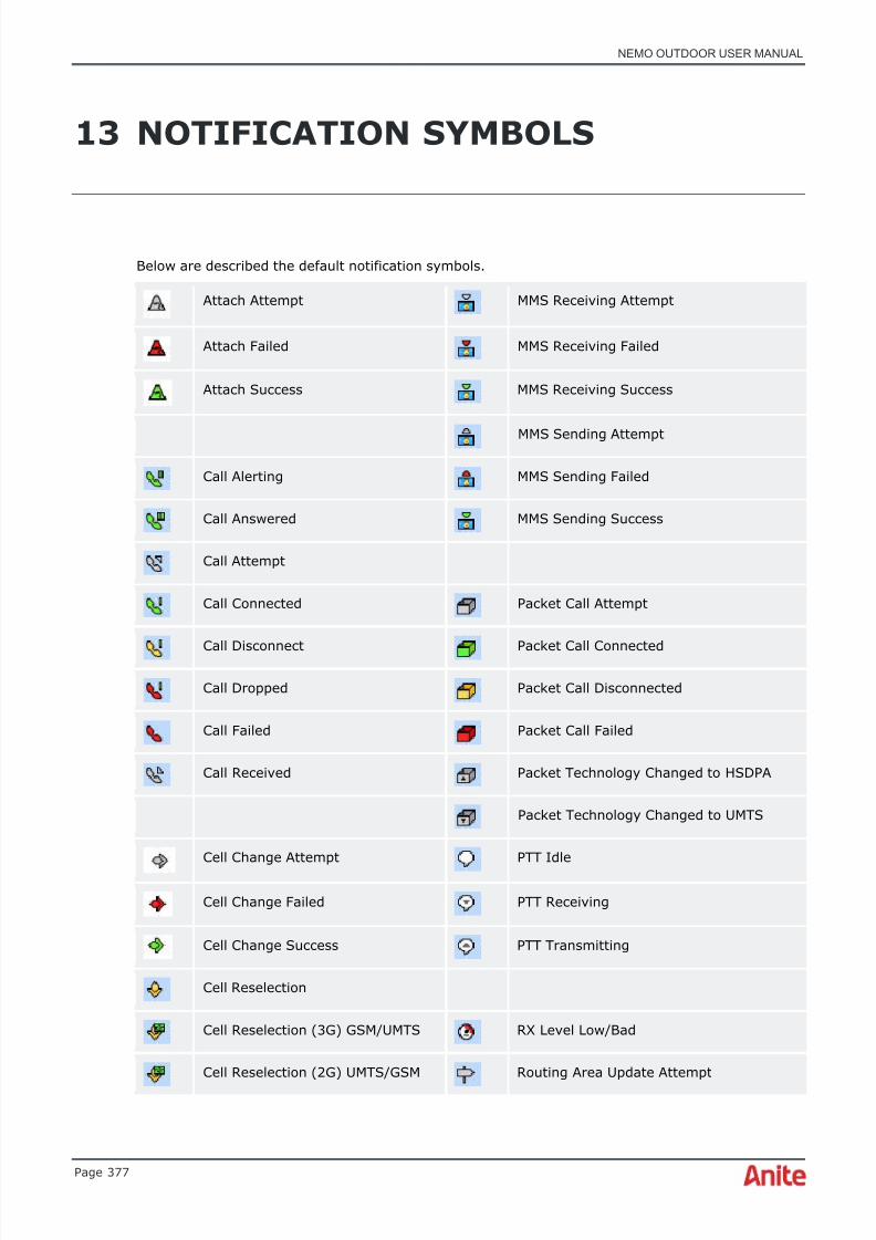
8/16/2019 Nemo Outdoor User Manual
http://slidepdf.com/reader/full/nemo-outdoor-user-manual 377/391
NEMO OUTDOOR USER MANUAL
Page 377
13 NOTIFICATION SYMBOLS
Below are described the default notification symbols.
Attach Attempt MMS Receiving Attempt
Attach Failed MMS Receiving Failed
Attach Success MMS Receiving Success
MMS Sending Attempt
Call Alerting MMS Sending Failed
Call Answered MMS Sending Success
Call Attempt
Call Connected Packet Call Attempt
Call Disconnect Packet Call Connected
Call Dropped Packet Call Disconnected
Call Failed Packet Call Failed
Call Received Packet Technology Changed to HSDPA
Packet Technology Changed to UMTS
Cell Change Attempt PTT Idle
Cell Change Failed PTT Receiving
Cell Change Success PTT Transmitting
Cell Reselection
Cell Reselection (3G) GSM/UMTS RX Level Low/Bad
Cell Reselection (2G) UMTS/GSM Routing Area Update Attempt

8/16/2019 Nemo Outdoor User Manual
http://slidepdf.com/reader/full/nemo-outdoor-user-manual 378/391
NEMO OUTDOOR USER MANUAL
Page 378
Routing Area Update Failed
Context Activation Attempt Routing Area Update Success
Context Activation Failed
Context Activation Success Semiduplex Call Attempt
Context Deactivation Service Lost
Service Received
Data Call Attempt
Data Connection Attempt SMS/USSD Received
Data Connection Failed SMS/USSD Receiving Attempt
Data Connection Success SMS/USSD Receiving Failed
Data Disconnect SMS/USSD Sending Completed
Data Transfer Attempt
Data Transfer Success Soft Handover Failure
Data Transfer Failed Soft Handover Success
Dead Reckoning in Use TX Power High/UL Power Up High
Detach
Differential GPS in Use Video Call Attempt
Duplex Call Attempt Voice Call Attempt/Voice Call Attempt(ETSI)
FER High Voice Call Connected (ETSI)
Voice Call Disconnected (ETSI)
GPS Fix Lost Voice Call Dropped (ETSI)
GPS Fix Received

8/16/2019 Nemo Outdoor User Manual
http://slidepdf.com/reader/full/nemo-outdoor-user-manual 379/391
NEMO OUTDOOR USER MANUAL
Page 379
HS-DSCH Serving Cell Changed Star
Thumb Down
Handover Attempt Thumb Up
Handover Failed
Handover Success
Location Area Update Attempt
Location Area Update Failed
Location Area Update Success
Marker
Markov Call Attempt
Measurement Error

8/16/2019 Nemo Outdoor User Manual
http://slidepdf.com/reader/full/nemo-outdoor-user-manual 380/391
NEMO OUTDOOR USER MANUAL
Page 380
14 TECHNICAL SUPPORT
If you have questions on or beyond this documentation about Nemo tools, please contact ourtechnical support service through Nemo Support Portal at http://nemosupport.anite.com , call us(local phone numbers can be found in chapter Phone and Email Support) or send us an email [email protected] . Note that for full support you need to have the Maintenance Agreement.
14.1 User Club
Nemo User Club offers several new ways to benefit from Nemo products. You can find it fromhttp://nemouserclub.anite.com .
Access to the Nemo User Club is restricted to customers with SW maintenance and TechnicalSupport agreements or partner agreements. If you are an existing Anite Finland customer with SWmaintenance and Technical Support agreements, but you are without access to the User Club,please complete an on-line registration form.
After submitting the requested information, you will receive a personal access key and password byemail in a few days’ time.
Once you are registered with our User Club, you will a u t o m a t i c a ll y receive e-mails informing youeach time a new version of software for your Nemo Product is released. It is fast, easy, and it is
available to you seven days a week, 24 hours a day.
14.2 Nemo Support Portal
Nemo Support Portal is a web interface for technical support, product-related questions, and RMArequests. It offers a fast and convenient way to reach our technical support team and submit repair,warranty repair, and calibration requests. Customers can open a support ticket, follow the status ofexisting tickets, and request technical support 24/7/365. Furthermore the Nemo Support Portalincludes a Knowledge Base for the most frequent and latest topics on Nemo Products. Submitting aticket via Nemo Support Portal ensures that our technical specialists have all the necessary
information available to solve your support case, resulting in faster response times.Please go to http://nemosupport.anite.com to access the portal and click “Request access” to obtaina password to the system.
14.3 Phone and Email Support
During the warranty period, the phone support related to potential software errors is free ofadditional charge. Registered users with a valid Maintenance Agreement are entitled to full support.Nemo Support Portal is the preferred channel for technical support requests, but you can also sendus an email. When emailing, please let us know the number of your Software Maintenance and
Support Agreement.Please contact us at the following locations (global email address [email protected]) :

8/16/2019 Nemo Outdoor User Manual
http://slidepdf.com/reader/full/nemo-outdoor-user-manual 381/391
NEMO OUTDOOR USER MANUAL
Page 381
Global
Tel. +358 50 395 7800
Americas
Tel. +1 469 951 9105+1 469 774 4608 (En español eportuguês)
APAC
Tel. +65 9746 2431
P.R. China
Tel. +86 10 6567 8528
India
Tel. +91 982 0016372
8/16/2019 Nemo Outdoor User Manual
http://slidepdf.com/reader/full/nemo-outdoor-user-manual 382/391
NEMO OUTDOOR USER MANUAL
Page 382
15 APPENDIX 1
15.1 Making MapInfo ® raster maps
Using raster image files, you can bring paper maps, photographs, and other graphic images intoMapInfo®. You can scan paper maps and then use paper maps as the foundation for the maps youcreate in MapInfo®. After scanning the paper map into a raster image file, you can display it in amap window.
Nemo Outdoor and Nemo Analyze support .TIF, .GIF, and .JPG formats. MapInfo ® can read thefollowing types of raster images:
• filename.TIF
• filename.GIF
• filename.JPG
• filename.PCX
• filename.BMP
• filename.BIL
Color options are:
• Monochrome images: each pixel in a map image can be black or white.
• Gray scale images: each pixel in a gray scale image can be black, white, or a shade of gray.
• Color images: each pixel can be of any color from a palette of available colors. MapInfo®supports 256 colors. When using Nemo Outdoor and Nemo Analyze, we recommend usinggray scale images. By doing this, the measurement route can be discerned better than withcolor map images.
15.1.1 Registering a raster map with MapInfo ® SW
If you want to overlay vector data on top of a raster image, then you must register the raster map
image so that MapInfo®
can position it properly in a Map window. You do this in the ImageRegistration Dialog. You must identify control point coordinates and the projection of the rasterimage map. It is important to provide accurate control point information when registering a rastermap image. Choose control points that can be easily identified and selected, such as streetintersections or use the coordinates (latitude and longitude grid) for the selected point from a papermap.
To register a raster map:
1. Start the MapInfo ® software. Choose File | Open Table and Raster Image File Format .Select your raster map image file (.TIF, .GIF, .JPG) and open it. The Image RegistrationDialog is displayed. A preview of the raster map image appears on the screen.
8/16/2019 Nemo Outdoor User Manual
http://slidepdf.com/reader/full/nemo-outdoor-user-manual 383/391
NEMO OUTDOOR USER MANUAL
Page 383
2. Select the Projection button to specify the projection of the raster image map. If you donot know the right projection, the default value is Longitude/ Latitude.
3. Start adding control points. Click on a location in the preview (raster image map). The AddControl Point Dialog is displayed showing the location of the point in pixels. Add Map X and
Map Y coordinates in decimal formats. For example, to specify the coordinates 65 degrees,30 minutes, enter 65.5 degrees. Use negative numbers when specifying west and southcoordinates. If you want to register a raster map that does not use longitude and latitudecoordinates, specify the appropriate projection in the Image Registration Dialog. Enter yourcoordinates in the native units of the coordinate system. For example, if you are registeringa UTM map image, enter coordinates in meters. Using the MapBasic ® program, you canconvert d/m/s coordinates into decimal degrees format, or the conversion from d/m/s todecimal degrees is as follows: degrees+(minutes/60)+(seconds/3600)=decimaldegrees
4. You must choose at least three control points. Select points that can be easily identified and
selected in the map window.5. After all control points have been defined, click OK in the Image Registration dialog. The
raster map will be displayed in the map window.
6. Move filename.tab and filename.tif/gif/jpg files to the map directory of Nemo Outdoor orNemo Analyze.
7. Open filename.tab in Nemo Outdoor or Nemo Analyze.
8/16/2019 Nemo Outdoor User Manual
http://slidepdf.com/reader/full/nemo-outdoor-user-manual 384/391
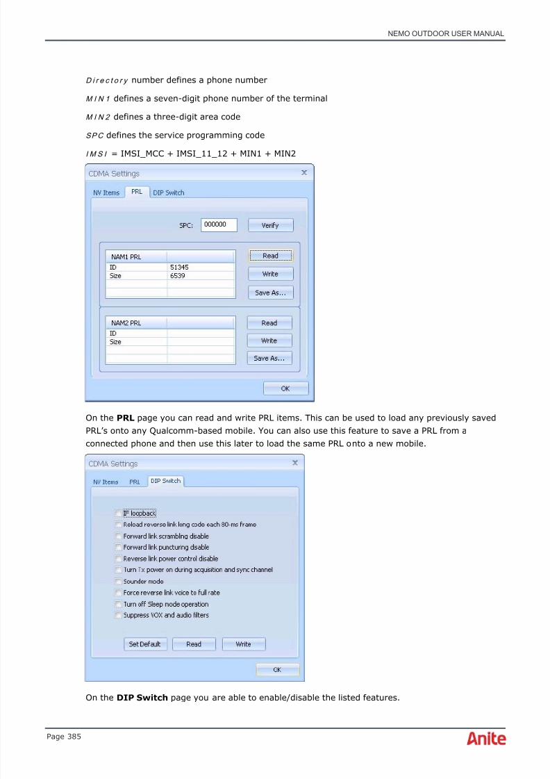
8/16/2019 Nemo Outdoor User Manual
http://slidepdf.com/reader/full/nemo-outdoor-user-manual 385/391
NEMO OUTDOOR USER MANUAL
Page 385
D i r e c t o r y number defines a phone number
M I N 1 defines a seven-digit phone number of the terminal
M I N 2 defines a three-digit area code
SP C defines the service programming codeI M S I = IMSI_MCC + IMSI_11_12 + MIN1 + MIN2
On the PRL page you can read and write PRL items. This can be used to load any previously savedPRL’s onto any Qualcomm-based mobile. You can also use this feature to save a PRL from aconnected phone and then use this later to load the same PRL onto a new mobile.
On the DIP Switch page you are able to enable/disable the listed features.
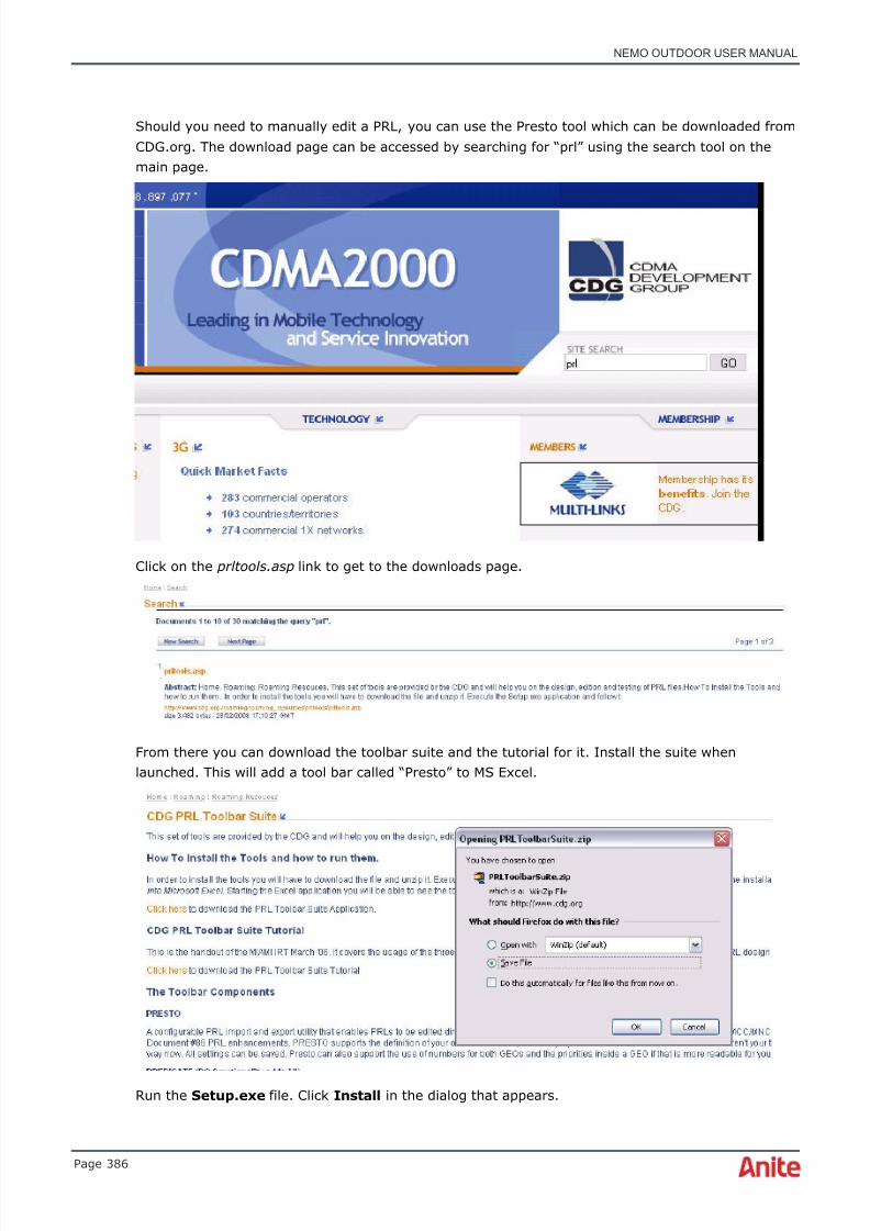
8/16/2019 Nemo Outdoor User Manual
http://slidepdf.com/reader/full/nemo-outdoor-user-manual 386/391
NEMO OUTDOOR USER MANUAL
Page 386
Should you need to manually edit a PRL, you can use the Presto tool which can be downloaded fromCDG.org. The download page can be accessed by searching for “prl” using the search tool on themain page.
Click on the prltools.asp link to get to the downloads page.
From there you can download the toolbar suite and the tutorial for it. Install the suite whenlaunched. This will add a tool bar called “Presto” to MS Excel.
Run the Setup.exe file. Click Install in the dialog that appears.
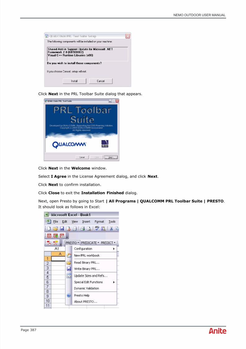
8/16/2019 Nemo Outdoor User Manual
http://slidepdf.com/reader/full/nemo-outdoor-user-manual 387/391
NEMO OUTDOOR USER MANUAL
Page 387
Click Next in the PRL Toolbar Suite dialog that appears.
Click Next in the Welcome window.
Select I Agree in the License Agreement dialog, and click Next .
Click Next to confirm installation.
Click Close to exit the Installation Finished dialog.
Next, open Presto by going to Start | All Programs | QUALCOMM PRL Toolbar Suite | PRESTO .It should look as follows in Excel:

8/16/2019 Nemo Outdoor User Manual
http://slidepdf.com/reader/full/nemo-outdoor-user-manual 388/391
NEMO OUTDOOR USER MANUAL
Page 388
17 END-USER LICENSE AGREEMENT
IMPORTANT - READ CAREFULLY : This End-User License Agreement ("EULA") is a legalagreement between you (either an individual or a single entity) and Anite Network Testing Ltd forthe Anite Network Testing Ltd software product(s), in whatever form, identified above ("SoftwareProduct" or "Software"). The Software Product includes computer software, the associated media,any printed materials, and any "online" or electronic documentation. By installing, copying orotherwise using the Software Product, you agree to be bound by the terms of this EULA. If you donot agree to the terms of this EULA, Anite Network Testing Ltd is unwilling to license the SoftwareProduct to you. In such event, you may not use or copy the Software Product, and you should
promptly return the unused product(s) in their original packaging to the place of purchase withinthirty days of the date of original purchase.
SOFTWARE PRODUCT LICENSE
The Software Product is protected by copyright laws and international copyright treaties, as well asother intellectual property laws and treaties. The Software Product is licensed, not sold.
1. GRANT OF LICENSE. This EULA grants you the following rights:
Software . You agree that the Software product is licensed to you to be used with the mobilephone(s) and software protection key designated by Anite Network Testing Ltd for such use("Designated Hardware"). You also agree that you shall not have more than one copy of the
Software Product in use at a time for any Designated Hardware in which the Software Product is tobe used or to be distributed except as expressly provided for in this EULA. You may use one copy ofthe Software Product in binary code form only on one computer at a time in order to conductsystem measurements using the Designated Hardware at various locations to the extent necessaryfor the permitted operation of the application software but may not duplicate the Software Product.
Storage/Network/Single Use . You may also store or install a copy of the Software Product inbinary code form only over an internal network, and distribute the Software Product to your othercomputers over an internal network. However, you must acquire and dedicate a license for theSoftware Product for each Designated Hardware on which the Software Product is used or to whichit is distributed. A license for the Software Product may not be shared or used concurrently on
different computers.2. DESCRIPTION OF OTHER RIGHTS AND LIMITATIONS.
Limitations on Reverse Engineering, Decompilation and Disassembly . Removal, emulation,or reverse engineering of all or any part of this product or its protection constitutes an unauthorizedmodification to the product and is specifically prohibited. Nothing in this license statement permitsyou to derive the source or assembly code of files provided to you in executable or object formats.
Limitations on Modifications, Adaptations and Other Changes . You may not modify, adapt orotherwise make any changes to the Software Product except and only to the extent you areexpressly permitted to do so under the applicable mandatory law notwithstanding this limitation orby Anite Network Testing Ltd's prior written consent.

8/16/2019 Nemo Outdoor User Manual
http://slidepdf.com/reader/full/nemo-outdoor-user-manual 389/391
NEMO OUTDOOR USER MANUAL
Page 389
Separation of Components . The Software Product is licensed as a single product. Its componentparts may not be separated for use on more than one Designated Hardware and computer asdesignated above.
Not for Resale . This Software Product is “Not for Resale" or "NFR" and your license only permits
personal use and you may not sell or otherwise transfer the Software Product for value except asspecified below.
Rental . You may not rent, lease or lend the Software Product to any person or entity.
Software Transfer . You may not otherwise give or permanently transfer any or all of your rightsunder this EULA without the express prior written consent of Anite Network Testing Ltd which suchconsent shall not be unreasonably withheld.
Security Mechanisms . Anite Network Testing and its affiliated companies take all legal steps toeliminate piracy of their software products. In this context, the Software may include a securitymechanism that can detect the installation or use of illegal copies of the Software, and collect and
transmit data about those illegal copies. Data collected will not include any customer data createdwith the Software. By using the Software, you consent to such detection and collection of data, aswell as its transmission and use if an illegal copy is detected. Anite Network Testing also reservesthe right to use a hardware lock device, license administration software, and/or a licenseauthorization key to control access to the Software. You may not take any steps to avoid or defeatthe purpose of any such measures. Use of any Software without any required lock device orauthorization key provided by Anite Network Testing is prohibited.
Duration and Termination . This EULA is effective from the day you open the sealed mediapackage or download and continues until termination. You may terminate this EULA at any time.Without prejudice to any other rights, Anite Network Testing Ltd may terminate this EULA if you failto comply with the terms and conditions of this EULA. In either event, you must destroy all copiesof the Software Product and all associated media, printed materials, updates and component partsand verify to Anite Network Testing Ltd in writing that such has been done.
3. SUPPORT SERVICES. Anite Network Testing Ltd may provide you with support services related tothe Software Product ("Support Services"). Any supplemental software code provided to you as partof the Support Services shall be considered part of the Software Product and subject to the termsand conditions of this EULA. With respect to technical information you provide to Anite NetworkTesting Ltd as part of the Support Services, Anite Network Testing Ltd may use such information forits business purpose, including for product updates and development.
4. COPYRIGHT AND TRADEMARKS. All title and copyrights in and to the Software Product (including
but not limited to any images, photographs, animations, video, audio, music, text and "applets",incorporated into the Software Product), the accompanying printed materials, and any copies of theSoftware Product, are owned by Anite Network Testing Ltd or its suppliers. The Software Product isprotected by copyright laws and international treaty provisions. You may not copy the printedmaterials accompanying the Software Product. You may not remove, modify or alter any AniteNetwork Testing Ltd copyright or trademark from any part of the Software Product, including butnot limited to any such notices contained in the physical and/or electronic media or documentation,in the Anite Network Testing Ltd Setup Wizard dialogue or 'about' boxes, in any of the runtimeresources and/or in any web-presence or web-enabled notices, code or other embodimentsoriginally contained in or dynamically or otherwise created by the Software Product.
The Software Product may include following licenses with related copyrights and titles:
WinWAP. Copyright © Winwap Technologies Oy. http://www.winwap.com
8/16/2019 Nemo Outdoor User Manual
http://slidepdf.com/reader/full/nemo-outdoor-user-manual 390/391
NEMO OUTDOOR USER MANUAL
Page 390
Perceptual Objective Listening Quality Analysis (POLQA) according to ITU-T Recommendation P. 863included in this product is protected by copyright and by European, US and other Internationalpatents and patent applications and is provided under license from
OPTICOM Dipl.-Ing. M. Keyhl GmbH, Erlangen, Germany, 2011 – www.opticom.de
POLQA® is a registered trademark of OPTICOM GmbH. Used by permission. © 2011 by the POLQACoalition of OPTICOM GmbH, Germany - SwissQual AG, Switzerland - KPN, The Netherlands - TNO,The Netherlands.
www.polqa.info
Further statements shall be incorporated to prohibit additional copying of the POLQA software inwhole or in part, other than is essential for the proper operation of the POLQA software or fornormal security back-up purposes; prevent the End-User from modifying, translating, reverse-engineering or decompiling the POLQA software except to the extent permitted by law; require thatthe acknowledgement of the rights in the POLQA software shall not be removed from the POLQA
software or any installation of it;
Perceptual Evaluation of Speech Quality (PESQ) measurement technology included in this product isprotected by copyright and by European, US and other patents and is provided under license fromOPTICOM Dipl.-Ing. M. Keyhl GmbH, Erlangen, Germany, 2008 - www.opticom.de
For further information please refer to www.pesq.org
Further statements shall be incorporated to prohibit additional copying of the PESQ software inwhole or in part, other than is essential for the proper operation of the PESQ software or for normalsecurity back-up purposes; prevent the End-User from modifying, translating, reverse-engineering
or decompiling the PESQ software except to the extent permitted by law; require that theacknowledgement of the rights in the PESQ software shall not be removed from the PESQ softwareor any installation of it;
Evaluation of Talker Quality (ECHO) measurement technology included in this product is protectedby copyright and is provided under license from
OPTICOM GmbH, Erlangen, Germany, 2011 - www.opticom.de
Further statements shall be incorporated to prohibit additional copying of the ECHO software inwhole or in part, other than is essential for the proper operation of the ECHO software or for normal
security back-up purposes; prevent the End-User from modifying, translating, reverse-engineeringor decompiling the ECHO software except to the extent permitted by law; require that theacknowledgement of the rights in the ECHO software shall not be removed from the ECHO softwareor any installation of it;
Libresample library and libVLC library distributed under LGPL license. For detailed information, seelicense files located in the software installation directory.
Skype is a trade mark of Skype or its related companies. This product/application has not been
approved or endorsed by Skype, Skype Communications S.a.r.l. or any of their related companies.
The license management portion of this Licensee Application is based on:

8/16/2019 Nemo Outdoor User Manual
http://slidepdf.com/reader/full/nemo-outdoor-user-manual 391/391
NEMO OUTDOOR USER MANUAL
SentinelRMS*
© 1989-2006 SafeNet, Inc.
All rights reserved
SentinelRMSe*
© 1989-2006 SafeNet, Inc.
All rights reserved
Iperf copyright. Copyright (c) 1999-2006, The Board of Trustees of the University of Illinois. AllRights Reserved. Permission is hereby granted, free of charge, to any person obtaining a copy of
this software (Iperf) and associated documentation files (the "Software"), to deal in the Softwarewithout restriction, including without limitation the rights to use, copy, modify, merge, publish,distribute, sublicense, and/or sell copies of the Software, and to permit persons to whom theSoftware is furnished to do so, subject to the following conditions: Redistributions of source codemust retain the above copyright notice, this list of conditions and the following disclaimers.Redistributions in binary form must reproduce the above copyright notice, this list of conditions andthe following disclaimers in the documentation and/or other materials provided with thedistribution. Neither the names of the University of Illinois, NCSA, nor the names of its contributorsmay be used to endorse or promote products derived from this Software without specific priorwritten permission. THE SOFTWARE IS PROVIDED "AS IS", WITHOUT WARRANTY OF ANY KIND,EXPRESS OR IMPLIED, INCLUDING BUT NOT LIMITED TO THE WARRANTIES OF MERCHANTABILITY,
FITNESS FOR A PARTICULAR PURPOSE AND NONINFRINGEMENT. IN NO EVENT SHALL THECONTIBUTORS OR COPYRIGHT HOLDERS BE LIABLE FOR ANY CLAIM, DAMAGES OR OTHERLIABILITY, WHETHER IN AN ACTION OF CONTRACT, TORT OR OTHERWISE, ARISING FROM, OUTOF OR IN CONNECTION WITH THE SOFTWARE OR THE USE OR OTHER DEALINGS IN THESOFTWARE.
5. DUAL-MEDIA SOFTWARE. You may receive the Software Product in more than one medium.Regardless of the type or size of medium you receive, you may use only that one medium that isappropriate for the systems you use to operate the Software Product. You may not use or installthe other medium on any system. You may not loan, rent, lease or otherwise transfer the othermedium to another user, except as part of the permanent transfer (as provided above) of the
Software Product.
6. CONFIDENTIALITY AND NON-DISCLOSURE. You agree to keep in confidence and not to disclosein any manner or form to any third party nor publish any such data or information related to theSoftware Product. You agree to protect all information and data provided to you by Anite NetworkTesting Ltd related to the Software Product with the same degree of care that you use to protect