ness radio keypadnesscorporation.com/installationmanual/ness_rkp_installer_manual.pdf · 3 the ness...
TRANSCRIPT

1
Installer ManUal
reV 5.1
Ness Radio Keypad – Installation and Programming Manual
N e s s RadIo KeyPad
R K PRADIO KEYPAD

2
WarnIngs & notIcesNess Corporation manufacturing processes are accredited to Iso9001 quality standards and all possible care and diligence has been applied during manufacture to ensure the reliable operation of this product. However there are various external factors that may impede or restrict the operation of this product in accordance with the product’s specification.These factors include, but are not limited to:1. erratic or reduced radio range (if radio accessories are installed). Ness radio products are sophisticated low
power devices, however the presence of in-band radio signals, high power transmissions or interference caused by electrical appliances such as Mains Inverters, Wireless Routers, Cordless Phones, Computers, TVs and other electronic devices may reduce radio range performance. While such occurrences are unusual, they are possible. In this case it may be necessary to either increase the physical separation between the Ness receiver and other devices or if possible change the radio frequency or channel of the other devices.
2. Unauthorised tampering, physical damage, electrical interruptions such as mains failure, electrical spikes or lightning.
3. solar power inverters are a known source of electrical interference. Please ensure that this product and all associated cabling is installed at least 3 metres away from a solar power inverter and its cabling.
WarnIng: Installation and maintenance to be performed only by qualified service personnel.caUtIon: Risk of explosion if battery is replaced by an incorrect type. dispose of used batteries in accordance with local regulations.aDsl notIce: adsL broadband data can interfere with the operation of your alarm dialler. It is recommended that a quality adsL filter be installed as per the filter manufacturer's guidelines in premises with an alarm dialler installed.
CoPyRIgHT NoTICe
all rights reserved. No part of this publication may be reproduced, transmitted or stored in a retrieval system in any form or by any means, electronic, mechanical, photocopying, recording, or otherwise, without the prior written permission of Ness.
Ness reserves the right to make changes to features and specifications at any time without prior notification in the interest of ongoing product development and improvement.
© 2016 Ness Corporation Pty Ltd aBN 28 069 984 372
RKP RadIo KeyPad INsTaLLaTIoN & PRogRaMMINg MaNUaL
document Part Number: 890-276
www.nesscorporation.com
National Customer service CentrePh: 1300 551 [email protected]

3
The Ness Radio Keypad (RKP) is a wireless, battery operated keypad designed for use with any Ness control panel which is compatible with the 100-200 Radio Interface.*
The RKP can also be used with other Ness receivers such as the 100-666 Ness MCR and the 100-187 Ness 1 Channel standalone Receiver.*
The Radio Keypad provides remote control of arming, disarming, Monitor (Home) modes and Panic facility.
Up to 15 User Codes can be programmed in the RKP. The Id for each code can be mapped to a compatible Ness control panel to report arming/disarming by User Id.
IntroDUctIon
R K PRADIO KEYPAD
PANIC buttons
“ ” lightLow Battery
“Valid” light
ARM button
HOME button
AUX 1 button
AUX 2 button
PROGRAM button
Protective flap not shown
ENTER button
90mm
135m
m
In addition, the aUX 1 button can be programmed to drive aUX 1 output at the control panel and aUX 2 can be used with the MCR receiver.
When used with a compatible Ness control panel and Radio Interface, the RKP can be used alongside Radio Keys and hardwired keypads.
Ness Radio Keypads can be:
Fixed - used in place of hardwired keypads in cases where it is not practical to run cables
Portable - carried from room to room, kept in a vehicle, bedside table.
* Receivers are sold separately.

4
Beeper
Battery compartment9V Lithium
RKP BODY REAR
• UncliptheRKPbodyfromthebackhousing
by pushing the top clips down with a small
screwdriver and pulling the RKP body
forward.
• If the RKP is being wall mounted; screw
the back housing to the wall using the four
mounting holes provided.
• Atthisstage,theRKPbodycanbehandheld
to insert the 9V battery as part of the powering
up process.
• Re-attach the RKP body
to the back housing by
first engaging the bottom
clips and swinging the top
closed. Push hard to ensure
the top clips engage.
InstallatIon
The RKP is powered by a 9V Lithium battery.
Battery life is approximately five years under normal conditions and use.
PoWer sUPPly
The RKP is compatible with:
ness radio Interface (100-200)Used with Ness control panels d8, d16 & d24.
ness standalone receiver (100-187) and ness Mcr multichannel receiver (100-666)Used with Ness 5000 series, PRo-L, PRo-Ld, PRo-LX, L8 and other control panels that can be armed/disarmed by a momentary contact closure.
coMPatIbIlIty
The keys are Led backlit. Backlighting turns on when any key is pressed and, to conserve power, turns off 5 seconds after the last key is pressed.
backlIghtIng
aNy KeyPRess
1 beep
VaLId CoMMaNd
3 beeps
eRRoR
1 long beep
ValIDloW battery
oFF Normal Normal
onUser Pogram Mode
option enabled (In Installer Program mode)
FlashIngInstaller Program Mode
RKP battery is low
1 FlashValid signal Transmitted
keyPaD beePs
keyPaD lIghts
5
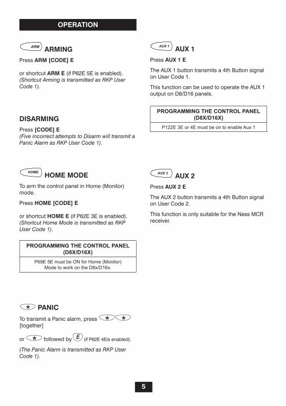
PanIc
To transmit a Panic alarm, press [together]
or followed by (if P62e 4eis enabled).
(The Panic Alarm is transmitted as RKP User Code 1).
aUX 2
Press aUX 2 e
The aUX 2 button transmits a 4th Button signal on User Code 2.
This function is only suitable for the Ness MCR receiver.
aUX 1
Press aUX 1 e
The aUX 1 button transmits a 4th Button signal on User Code 1.
This function can be used to operate the aUX 1 output on d8/d16 panels.
arMIng
Press arM [coDe] e
or shortcut arM e (if P62e 5e is enabled).(Shortcut Arming is transmitted as RKP User Code 1).
DIsarMIng
Press [coDe] e(Five incorrect attempts to Disarm will transmit a Panic Alarm as RKP User Code 1).
hoMe MoDe
To arm the control panel in Home (Monitor) mode.
Press hoMe [coDe] e
or shortcut hoMe e (if P62e 3e is enabled).(Shortcut Home Mode is transmitted as RKP User Code 1).
oPeratIon
Programming the Control Panel(D8x/D16x)
P69E 5E must be ON for Home (Monitor)Mode to work on the D8x/D16x.
Programming the Control Panel(D8x/D16x)
P122E 3E or 4E must be on to enable Aux 1

6
tyPIcal systeM
User coDe MaPPIng oPtIons
Hardwired Keypad/s (max. 3)
RadIo KeyPad
RadIo Keys
(Maximum 55 Radio Keys or Radio Keypads.)
RadIo INTeRfaCe (100-200)
d8X/d16X CoNTRoL PaNeL
senD User IDs DIsableDP09e, 0e = off (factory default)(When programming, Low Battery light = off)
RKP Codes
PaNeL Codes
senD User IDs enableDP09e, 0e = oN(When programming, Low Battery light = oN)
RKP UseR 1To any panel user code slot
aLL UseR Codes aRe TRaNsMITTed as UseR 1.Note 1: only RKP User Id 1 needs to be 'learned' by the panel. It can be learned to any panel user slot from 2–56.Note 2: The control panel user code 1 is always a keypad code.
d8x
/d16
x C
ontr
ol P
anel
RKP Codes
PaNeL Codes
d8x
/d16
x C
ontr
ol P
anel
aLL UseR Codes aRe INdIVIdUaLLy TRaNsMITTed.Note 1: all RKP User Ids must be individually 'learned' by the panel.Note 2: The control panel user code 1 is always a keypad code.

7
PrograMMIng oPtIons
The RKP program options on page 12 in the Ness Radio Keypad.
These options are not to be confused with similar program options stored in Ness control panels.
User PrograM MoDe
User Program Mode allows the owner to program User Codes 1–15.
To eNTeR UseR PRogRaM Mode: P [Master code] e ‘Valid’ light will turn on.
Installer PrograM MoDe
Installer Program Mode allows the installer to program all options.
To eNTeR INsTaLLeR PRogRaM Mode: From User Program Mode...
P [Installer code] e ‘Valid’ light will be flashing.
to eXIt PrograM MoDe
from any Program Mode...
P e ‘Valid’ light will turn off.
PrograM lIghts
In Program Mode, the Valid and Low Battery lights provide visual indication as follows.
Program options P09E, P10E and P62E.LoW BaTTeRy light
oN = The option is oN off = The option is off
VaLId lightoN = User program modefLasHINg = Installer Program modeoff = Normal operating mode
PrograMMIng the rkP
note: The RKP will automatically drop out of User or Installer Program Mode to operating Mode 3 minutes after the last key press.
PoWer UP DeFaUlt:
To default the RKP on power up, insert the battery while pressing the aRM and e buttons together.
This resets all options to factory default values. The RKP will then be in normal operating mode.

8
PrograMMIng the rkP to the Panel
MethoD 1. WIthoUt User ID (Individual rkP user IDs are not sent)
P09e 0e is off (factory default).
To program the RKP to the control panel, first put the panel in Radio Key ‘learn’ mode (any user code), then connect the RKP battery. The RKP sends its Learn Message and the Valid light will flash once.
example
Programming the RKP to a d8x or d16x panel.1
control Panel (Installer Program mode)
1. Press P256e eXclUDe e 5e eXclUDe e This enables the panel’s user code 56 as a Radio Code. (you can use any user code from 2 to 56).
2. Press 1e to prepare user code 56 to accept a Radio Code.
rkP
3. Insert the rkP battery or in installer program mode, press P09e 1e. (sends the learn message for User Code 1).
The RKP and the control panel are now ready for use. The RKP will arm and disarm the panel via the Radio Code programmed.
The panel can now be operated by RKP, its hardwired keypad and/or additional RKPs or Radio Keys.
In this example, if the panel is monitored via dialler by a central station, when the panel is armed/disarmed by the RKP, (using any RKP user code), it will report arm/disarm (any RKP user code) via the panel user Id of 56.
1 The control panel must have the Ness Radio Interface installed. Part Number 100-200.
MethoD 2. WIth User ID (rkP User IDs are mapped to panel codes)
P09e 0e is on.
If you need to send open/close reports with individual User Ids to the central station, each RKP User Id needs to be ‘learned’ into the control panel.
example
Programming the RKP to a d8x or d16x panel.1
Mapping 14 RKP User Ids to the panel.
control Panel (Installer Program mode)
1. Press P242e eXclUDe e 5e eXclUDe e This enables the panel’s user code 42 as a Radio Code.
2. Press 1e to prepare the user code to accept a Radio Code.
rkP (Installer Program mode)3. Press P09e 1e to send the Learn Message
for RKP User Id 1.
Repeat steps 2 & 3 for the remaining user codes (P242e to P256e). This process is the same as programming 14 Radio Keys to a d8x or d16x control panel.
What Is a ‘learn Message’?
a Learn Message includes the full 56 bit message string which identifies a User Id. The Learn Message is required to be sent when you program (or ‘learn’) the RKP to the control panel, (or Ness standalone receiver).
hoW to senD a ‘learn Message’
From power-up: Insert the RKP battery and the Learn Message for RKP User Id 1 is automatically sent.
Installer Program Mode: The Learn Message for each RKP User Id 1–15 can be sent individually by pressing P09e 1e, 2e, 3e etc.
send User Ids (P09e 0e) must be enabled).
The RKP Low Battery light flashes 3 times each time a learn Message is sent.

9
P09e senD User IDs
This option enables the transmission of individual User Ids to the control panel.
To program, press P09e 0e then press 0e to toggle the option on and off.
P09e 0e = oFF: User Ids disabled, (Low Battery light is off, factory default).
all the RKP user codes are transmitted to the control panel as User Id 1.
This is the best option if you do not intend to send open/close reports with User Id to the central station. This is also the easiest to program because only the Id for RKP user code 1 needs to be ‘learned’ by the control panel.
The RKP user code 1 can be programmed to any panel code except the master code.
P09e 0e = on: User Ids enabled, (Low Battery light is oN).
each RKP user code is individually transmitted to the control panel, (as User Ids 1–15).This is used for sending open/close reports with User Id to the central station.The User Ids must be ‘learned’ into the control panel one at a time.
PrograM oPtIons P10e enable raDIo encryPtIon
P10e 0000e: auto site Code, (Low Battery light is oN, factory default).
The site Code is the encrypted security code that the RKP transmits to the panel along with the button press data.
By entering P10e 0000e, the site Code is automatically generated when the learn message is sent to the panel.
P10e [4 digit code site code] e: Manual site Code, (Low Battery light is off).
This option can be used to manually set the transmitted code. This is only necessary if multiple RKPs are programmed to the same panel code.
P11e–P25e User coDes 1–15
The RKP can be programmed with 15 user codes of 3–6 digits in length.
User Codes cannot start with the digit 0.
To program a user code:P [option No] e [New code] e [New code] e
When programming:Low Battery light off = The code is blankLow Battery light oN = a code is programmed
To clear a user code:P [option No] e 0e 0e
User coDes / User IDs DeFIneD.
User codes are stored in the RKP and are not transmitted to the panel.
The panel receives an encrypted message representing the User ID of the code being used.
The RKP’s user codes are independent to the control panel’s user codes.
10
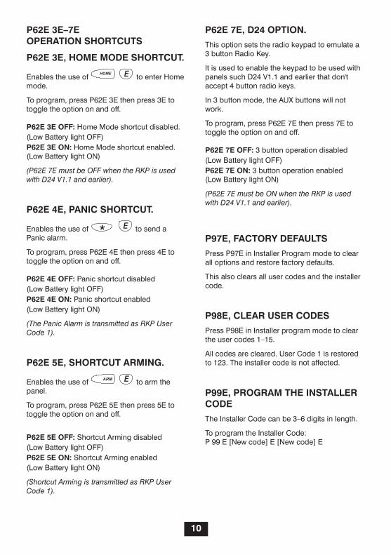
P62e 3e–7e oPeratIon shortcUts
P62e 3e, hoMe MoDe shortcUt.
enables the use of to enter Home mode.
To program, press P62e 3e then press 3e to toggle the option on and off.
P62e 3e oFF: Home Mode shortcut disabled.(Low Battery light off)P62e 3e on: Home Mode shortcut enabled.(Low Battery light oN)
(P62E 7E must be OFF when the RKP is used with D24 V1.1 and earlier).
P62e 4e, PanIc shortcUt.
enables the use of to send a Panic alarm.
To program, press P62e 4e then press 4e to toggle the option on and off.
P62e 4e oFF: Panic shortcut disabled(Low Battery light off)P62e 4e on: Panic shortcut enabled(Low Battery light oN)
(The Panic Alarm is transmitted as RKP User Code 1).
P62e 5e, shortcUt arMIng.
enables the use of to arm the panel.
To program, press P62e 5e then press 5e to toggle the option on and off.
P62e 5e oFF: shortcut arming disabled(Low Battery light off)P62e 5e on: shortcut arming enabled(Low Battery light oN)
(Shortcut Arming is transmitted as RKP User Code 1).
P62e 7e, D24 oPtIon.
This option sets the radio keypad to emulate a 3 button Radio Key.
It is used to enable the keypad to be used with panels such d24 V1.1 and earlier that don't accept 4 button radio keys.
In 3 button mode, the aUX buttons will not work.
To program, press P62e 7e then press 7e to toggle the option on and off.
P62e 7e oFF: 3 button operation disabled(Low Battery light off)P62e 7e on: 3 button operation enabled(Low Battery light oN)
(P62E 7E must be ON when the RKP is used with D24 V1.1 and earlier).
P97e, Factory DeFaUlts
Press P97e in Installer Program mode to clear all options and restore factory defaults.
This also clears all user codes and the installer code.
P98e, clear User coDes
Press P98e in Installer program mode to clear the user codes 1–15.
all codes are cleared. User Code 1 is restored to 123. The installer code is not affected.
P99e, PrograM the Installer coDe
The Installer Code can be 3–6 digits in length.
To program the Installer Code:P 99 e [New code] e [New code] e

11
rkP oPtIon DescrIPtIon DeFaUlt
P09e 0e send User Ids 123
P09e 1e-15e sent Learn Message for codes 1 to 15
P10e enable Radio encryption oN
P11e User Code 1 (Master Code) 123
P12e User Code 2
P13e User Code 3
P14e User Code 4
P15e User Code 5
P16e User Code 6
P17e User Code 7
P18e User Code 8
P19e User Code 9
P20e User Code 10
P21e User Code 11
P22e User Code 12
P23e User Code 13
P24e User Code 14
P25e User Code 15
P62e 3e Home Mode shortcut oN
4e enable Panic oN
5e arming shortcut oN
7e d24 option off
P97eRestore factory defaults
(This defaults all options including user codes and installer code)
P98e Clear User Codes 1 to 15
P99e Installer Code 000000
PrograM oPtIons table

12
sPecIFIcatIons
dimensions ............................... 90W x 135H x 27d mm (with lid closed).
Compatibility ............................. 100-200 Ness Radio Interface. 100-187 Ness 1ch standalone Receiver. 100-666 Ness MCR receiver.
Keypad functions ...................... arming by User Id disarming by User Id Home mode Panic alarm aux 1 (to d8x & d16x panels) aux 2 (to MCR Receiver)
audible indicator ....................... onboard beeper for feedback: keypress, valid command, error.
Visual indicators ....................... VaLId Led: indicates program modes, valid signal. LoW BaTTeRy Led: indicates RKP low battery, option enabled (pro-gram mode).
Battery ....................................... 9V Lithium (Ultralife U9VL)
Quiescent current draw ............ 11µa
Radio transmitter ....................... saWR stabilised
Radio frequency ........................ 304MHz
Transmit power.......................... 100µW PeP
When used with the 100-200 Radio Interface