netlink pro family · pdf filewincc v7.4 (siemens ag) ... 3 helmholz opc-server v4.12.0.11527...
TRANSCRIPT
Helmholz GmbH & Co. KG | Hannberger Weg 2 | 91091 Großenseebach | Germany Phone: +49 9135 7380-0 | Fax: +49 9135 7380-110 | E-Mail: [email protected] | Internet: www.helmholz.de
NETLink® PRO family Application Examples with RFC 1006 Edition 7 / 05.11.2017
Helmholz products S7/S5 OPC-Server V4.10.2.9117 (Company Helmholz)
Products of other manufacturers INAT-OPC-Server (INAT GmbH)
Indusoft Web Studio V7.0 (Indusoft)
InTouch V9.5 (Wonderware GmbH)
KEPserverEx V5.4.135.0 (KEPware Inc.)
PROCON-Win V5.3 (GTI Control)
VisAM Win32 (VISAM GmbH)
WinCC V7.4 (Siemens AG)
WinCC flexible 2005/2007 (Siemens AG)
ZenOn V6.2 (COPA-DATA)
All rights are reserved, including those of translation, reprinting, and reproduction of this manual, or parts thereof. No part of this manual may be reproduced, processed, copied, or transmitted in any way whatsoever (photocopy, microfilm, or other method) without the express written permission of Helmholz GmbH & Co.KG, not even for use as training material, or using electronic systems. All rights reserved in the case of a patent grant or registration of a utility mod-el or design.
Copyright © 2009 by
Helmholz GmbH & Co.KG
Hannberger Weg 2, 91091 Grossenseebach, Germany
Note:
We have checked the content of this manual for conformity with the hardware and software described. Nevertheless, because devia-tions cannot be ruled out, we cannot accept any liability for com-plete conformity. The information in this manual is regularly up-dated. When using purchased products, please heed the latest ver-sion of the manual, which can be viewed in the Internet at www.helmholz.com, from where it can also be downloaded.
Our customers are important to us. We are always glad to receive suggestions for improvement and ideas.
STEP ,Protool, Starter, Micromaster, and SIMATIC are registered trademarks of SIEMENS AG MS-DOS and Windows are registered trademarks of Microsoft Corporation.

NETLink® PRO family Application Examples 3
Revision history of this document:
Edition Date Revision
1 07.05.2008 First edition
2 07.04.2010 PRO family updated
3 29.11.2010 KEPserverEx V5.4.135.0 updated
4 04.07.2011 Helmholz OPC Server V4.0.6.4908 updated
5 05.08.2011 Added Indusoft Web Studio V7.0 and PROCON-Win V5.3
6 15.08.2012 Added WINCC V7.0
7 04.10.2017 Added WINCC V7.4
8 30.10.2017 KEPServer V6.2.429.0 updated
NETLink® PRO family Application Examples 4
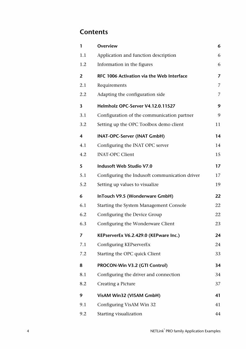
Contents
1 Overview 6
1.1 Application and function description 6
1.2 Information in the figures 6
2 RFC 1006 Activation via the Web Interface 7
2.1 Requirements 7
2.2 Adapting the configuration side 7
3 Helmholz OPC-Server V4.12.0.11527 9
3.1 Configuration of the communication partner 9
3.2 Setting up the OPC Toolbox demo client 11
4 INAT-OPC-Server (INAT GmbH) 14
4.1 Configuring the INAT OPC server 14
4.2 INAT-OPC Client 15
5 Indusoft Web Studio V7.0 17
5.1 Configuring the Indusoft communication driver 17
5.2 Setting up values to visualize 19
6 InTouch V9.5 (Wonderware GmbH) 22
6.1 Starting the System Management Console 22
6.2 Configuring the Device Group 22
6.3 Configuring the Wonderware Client 23
7 KEPserverEx V6.2.429.0 (KEPware Inc.) 24
7.1 Configuring KEPserverEx 24
7.2 Starting the OPC quick Client 33
8 PROCON-Win V3.2 (GTI Control) 34
8.1 Configuring the driver and connection 34
8.2 Creating a Picture 37
9 VisAM Win32 (VISAM GmbH) 41
9.1 Configuring VisAM Win 32 41
9.2 Starting visualization 44
NETLink® PRO family Application Examples 5
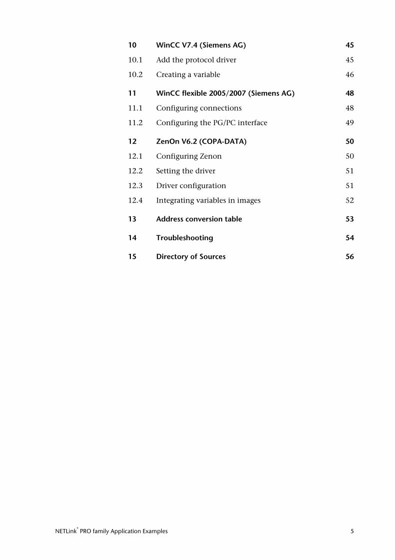
10 WinCC V7.4 (Siemens AG) 45
10.1 Add the protocol driver 45
10.2 Creating a variable 46
11 WinCC flexible 2005/2007 (Siemens AG) 48
11.1 Configuring connections 48
11.2 Configuring the PG/PC interface 49
12 ZenOn V6.2 (COPA-DATA) 50
12.1 Configuring Zenon 50
12.2 Setting the driver 51
12.3 Driver configuration 51
12.4 Integrating variables in images 52
13 Address conversion table 53
14 Troubleshooting 54
15 Directory of Sources 56
NETLink® PRO family Application Examples 6
1 Overview
1.1 Application and function description
This document is intended as a supplement to the NETLink® product line manuals.
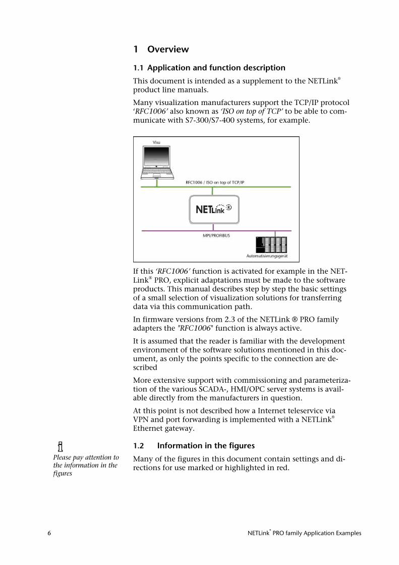
Many visualization manufacturers support the TCP/IP protocol ‘RFC1006’ also known as ‘ISO on top of TCP’ to be able to com-municate with S7-300/S7-400 systems, for example.
If this ‘RFC1006’ function is activated for example in the NET-Link® PRO, explicit adaptations must be made to the software products. This manual describes step by step the basic settings of a small selection of visualization solutions for transferring data via this communication path.
In firmware versions from 2.3 of the NETLink ® PRO family adapters the "RFC1006" function is always active.
It is assumed that the reader is familiar with the development environment of the software solutions mentioned in this doc-ument, as only the points specific to the connection are de-scribed
More extensive support with commissioning and parameteriza-tion of the various SCADA-, HMI/OPC server systems is avail-able directly from the manufacturers in question.
At this point is not described how a Internet teleservice via VPN and port forwarding is implemented with a NETLink® Ethernet gateway.
1.2 Information in the figures
Many of the figures in this document contain settings and di-rections for use marked or highlighted in red.
Please pay attention to the information in the figures
NETLink® PRO family Application Examples 7
2 RFC 1006 Activation via the Web Interface The examples described here are based on NETLink models with firmware versions less than V2.3 (e.g. NETLink ® PRO). Prior to the use with this device the RFC 1006 functionality has to be set manually.
A detailed description is also given in the accordingly manual! We generally recommend upgrading your NETLink® products with the last firmware version, so you can always use the latest features.
2.1 Requirements
The NETLink® Ethernet gateway is connected to the PC via a network card. One of the SCADA/OPC server programs de-scribed below is also installed on this PC. The Webinterface function must not be deactivated. It is accessed via one of the installed Internet browsers (for example, Mozilla Firefox, Op-era, Konqueror, or Internet Explorer).
You do not need to install any additional drivers for the NET-Link®.
The applications described here were performed on the Win-dow XP operating system with service package 2 and 3.
2.2 Adapting the configuration side
As soon as the Web interface is opened by entering the rele-vant URL ‘http://<ip address>’, the link to “Configuration” opens. As soon as you have answered the security query, you can write to all parameters.
From version 2.3 there is a text field: "RFC mode is always acti-vated". In this case, you can skip this section.
The ‘RFC 1006 interface ON/OFF’ option is activated by entering “ON” and confirming with the “OK” button (see Fig.)
In the next window, the settings are displayed again and must be confirmed with “OK” before they are finally transferred to the NETLink® device.
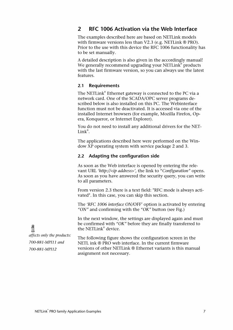
The following figure shows the configuration screen in the NETL ink ® PRO web interface. In the current firmware versions of other NETLink ® Ethernet variants is this manual assignment not necessary.
affects only the products:
700-881-MPI11 and
700-881-MPI12
NETLink® PRO family Application Examples 8
Configuration menu in NETLink® PRO:
After the new parameterization data have been stored, the NETLink® PRO is restarted to activate the new configuration.
Rebooting can take up to 15 seconds.
NETLink® PRO family Application Examples 9
3 Systeme Helmholz OPC-Server V4.12.0.11527
The following steps must be performed in the described se-quence (Version November 2017):
3.1 Configuration of the communication partner
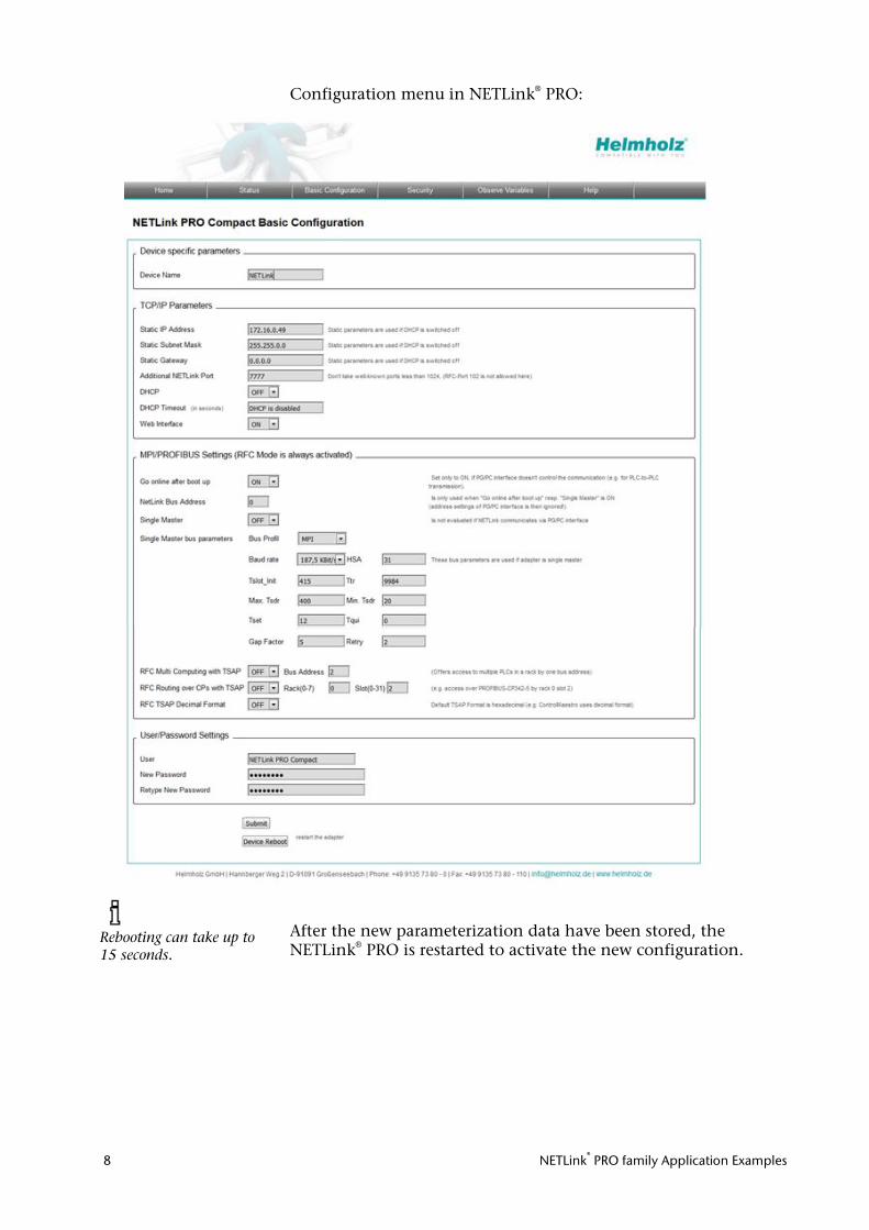
Start the “Configuration S7-OPC Server” program module via Start/Programs/Systeme Helmholz/S7-OPC-Server:
• Select tab card “Devices”. • In this example, click device 0 and then select “S7-TCP/IP”
from the pull-down menu.
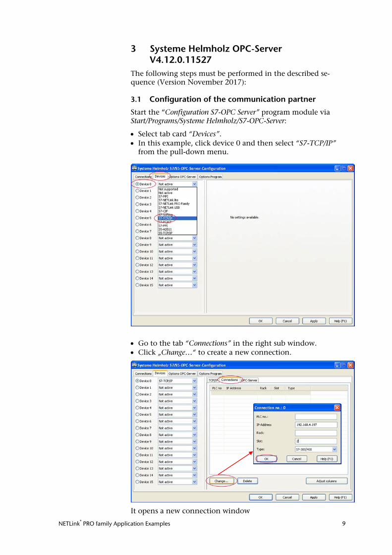
• Go to the tab “Connections” in the right sub window. • Click „Change…“ to create a new connection.
It opens a new connection window
NETLink® PRO family Application Examples 10
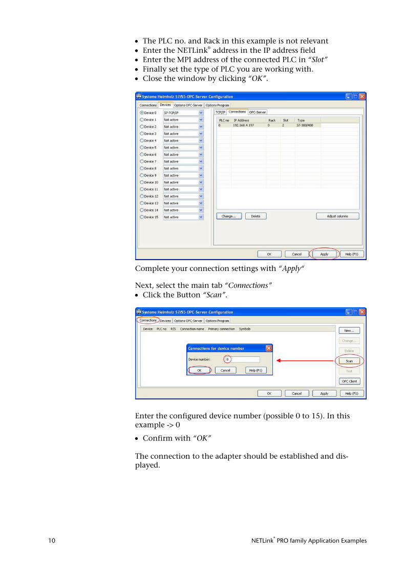
• The PLC no. and Rack in this example is not relevant • Enter the NETLink® address in the IP address field • Enter the MPI address of the connected PLC in “Slot” • Finally set the type of PLC you are working with. • Close the window by clicking “OK”.
Complete your connection settings with “Apply“
Next, select the main tab “Connections” • Click the Button “Scan”.
Enter the configured device number (possible 0 to 15). In this example -> 0
• Confirm with “OK” The connection to the adapter should be established and dis-played.
NETLink® PRO family Application Examples 11
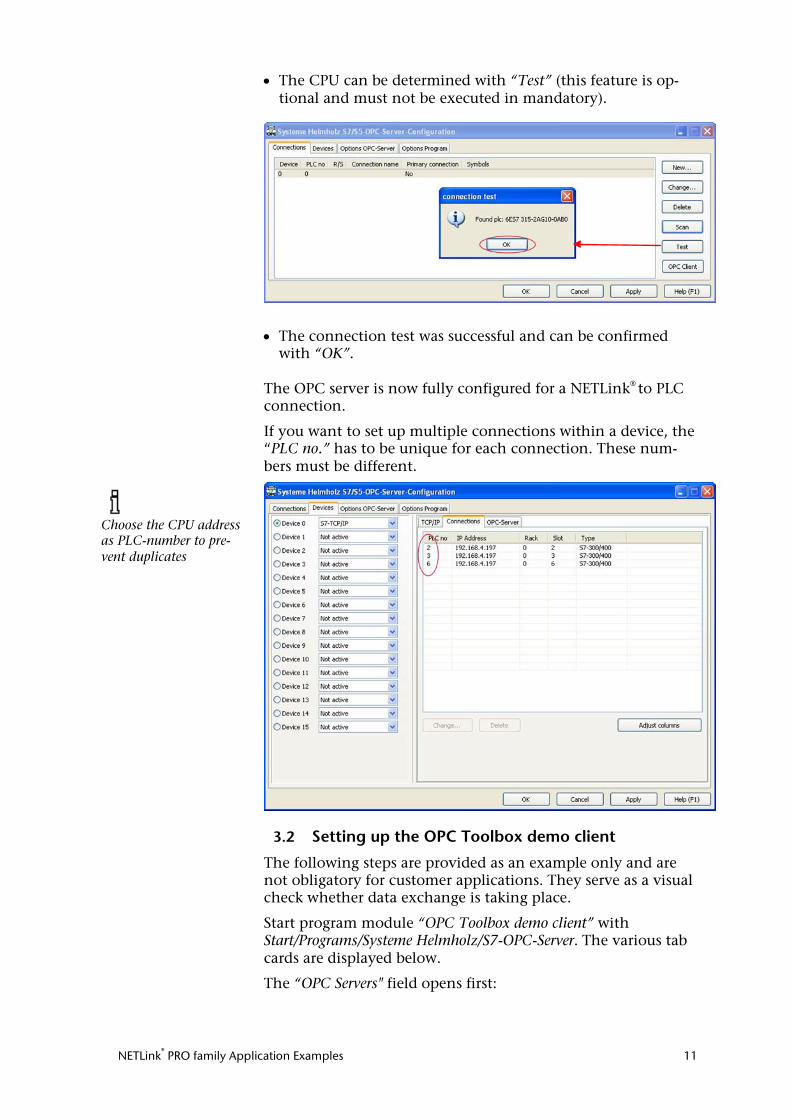
• The CPU can be determined with “Test” (this feature is op-tional and must not be executed in mandatory).
• The connection test was successful and can be confirmed with “OK”.
The OPC server is now fully configured for a NETLink® to PLC connection.
If you want to set up multiple connections within a device, the “PLC no.” has to be unique for each connection. These num-bers must be different.
3.2 Setting up the OPC Toolbox demo client
The following steps are provided as an example only and are not obligatory for customer applications. They serve as a visual check whether data exchange is taking place.
Start program module “OPC Toolbox demo client” with Start/Programs/Systeme Helmholz/S7-OPC-Server. The various tab cards are displayed below.
The “OPC Servers" field opens first:
Choose the CPU address as PLC-number to pre-vent duplicates
NETLink® PRO family Application Examples 12
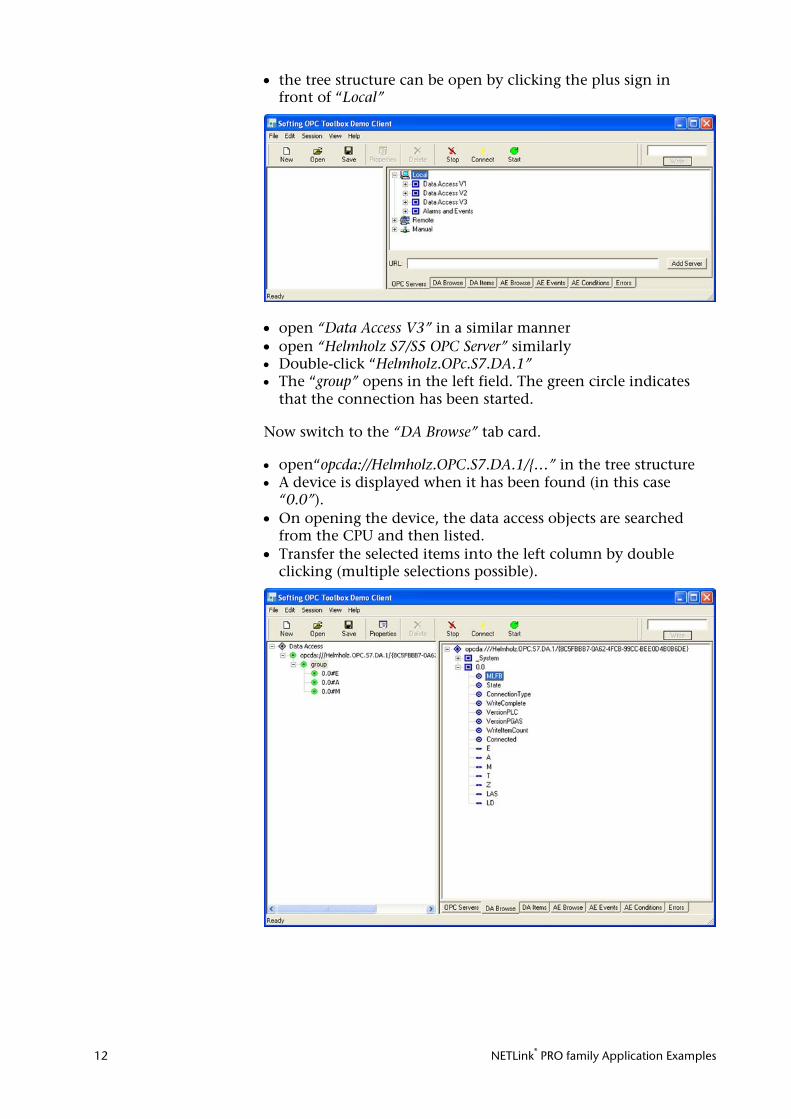
• the tree structure can be open by clicking the plus sign in front of “Local”
• open “Data Access V3” in a similar manner • open “Helmholz S7/S5 OPC Server” similarly • Double-click “Helmholz.OPc.S7.DA.1” • The “group” opens in the left field. The green circle indicates
that the connection has been started.
Now switch to the “DA Browse” tab card. • open“opcda://Helmholz.OPC.S7.DA.1/{…” in the tree structure • A device is displayed when it has been found (in this case
“0.0”). • On opening the device, the data access objects are searched
from the CPU and then listed. • Transfer the selected items into the left column by double
clicking (multiple selections possible).
NETLink® PRO family Application Examples 13
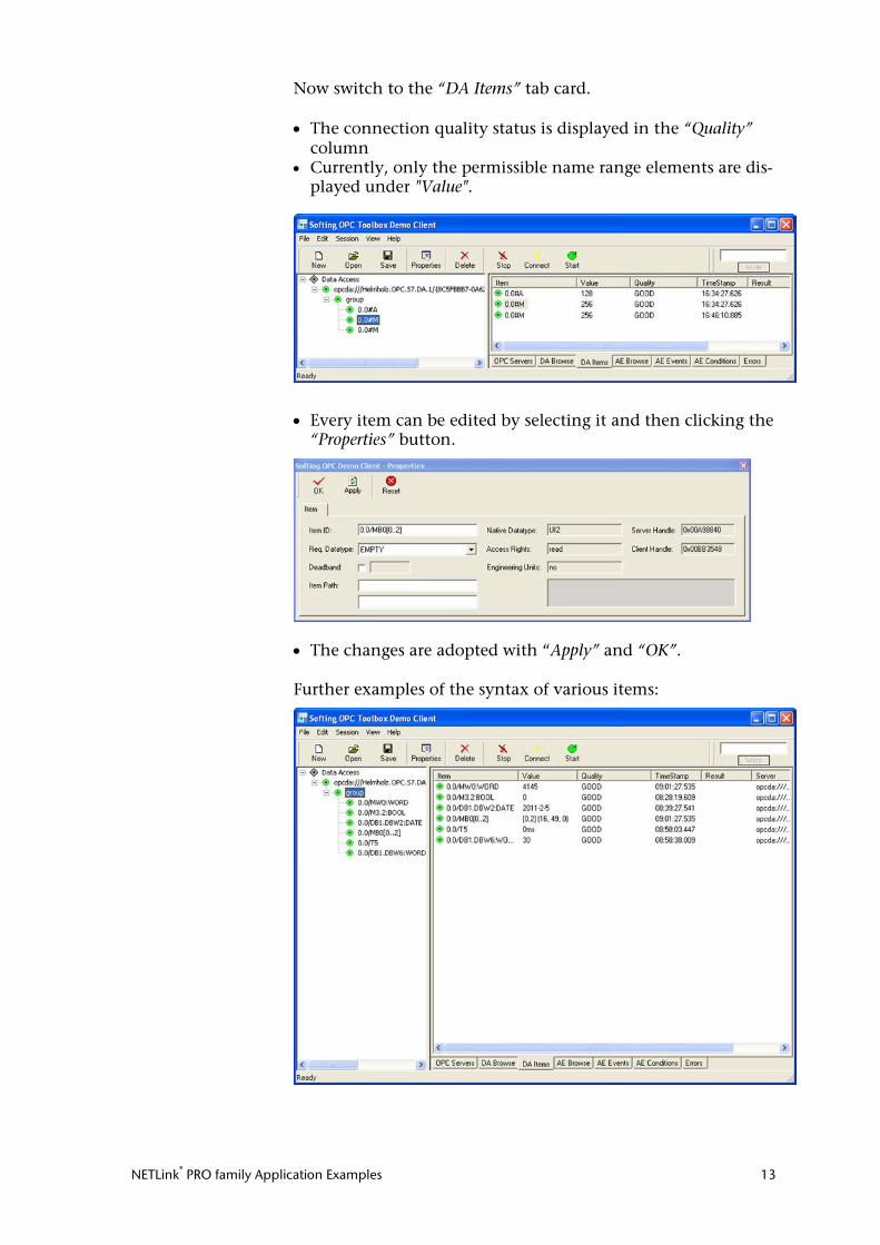
Now switch to the “DA Items” tab card. • The connection quality status is displayed in the “Quality”
column • Currently, only the permissible name range elements are dis-
played under "Value".
• Every item can be edited by selecting it and then clicking the “Properties” button.
• The changes are adopted with “Apply” and “OK”. Further examples of the syntax of various items:
NETLink® PRO family Application Examples 14
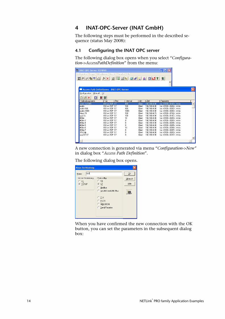
4 INAT-OPC-Server (INAT GmbH) The following steps must be performed in the described se-quence (status May 2008):
4.1 Configuring the INAT OPC server
The following dialog box opens when you select “Configura-tion->AccessPathDefinition” from the menu:
A new connection is generated via menu “Configuration->New” in dialog box “Access Path Definition”.
The following dialog box opens.
When you have confirmed the new connection with the OK button, you can set the parameters in the subsequent dialog box:
NETLink® PRO family Application Examples 15
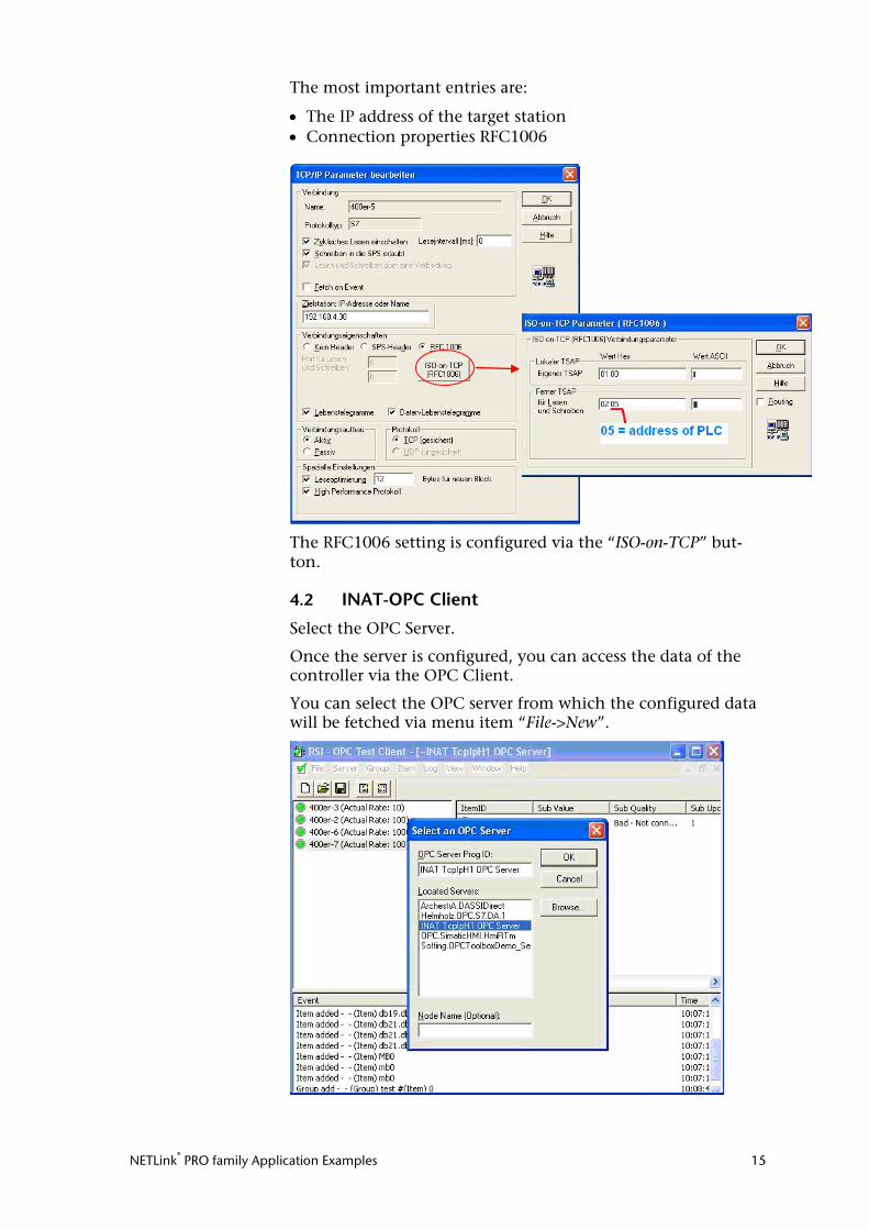
The most important entries are:
• The IP address of the target station • Connection properties RFC1006
The RFC1006 setting is configured via the “ISO-on-TCP” but-ton.
4.2 INAT-OPC Client
Select the OPC Server.
Once the server is configured, you can access the data of the controller via the OPC Client.
You can select the OPC server from which the configured data will be fetched via menu item “File->New”.
NETLink® PRO family Application Examples 16
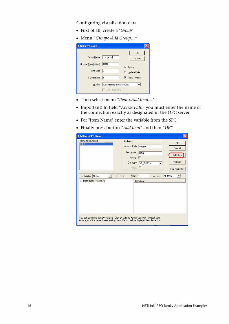
Configuring visualization data
• First of all, create a "Group"
• Menu “Group->Add Group…”
• Then select menu “Item->Add Item…”
• Important! In field “Access Path” you must enter the name of the connection exactly as designated in the OPC server
• For "Item Name" enter the variable from the SPC
• Finally press button “Add Item” and then “OK”
NETLink® PRO family Application Examples 17
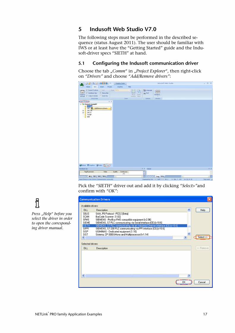
5 Indusoft Web Studio V7.0 The following steps must be performed in the described se-quence (status August 2011). The user should be familiar with IWS or at least have the “Getting Started” guide and the Indu-soft-driver specs “SIETH” at hand.
5.1 Configuring the Indusoft communication driver
Choose the tab „Comm“ in „Project Explorer“, then right-click on “Drivers” and choose “Add/Remove drivers”:
Pick the “SIETH“ driver out and add it by clicking “Select>”and confirm with “OK”:
Press „Help“ before you select the driver in order to open the correspond-ing driver manual.
NETLink® PRO family Application Examples 18
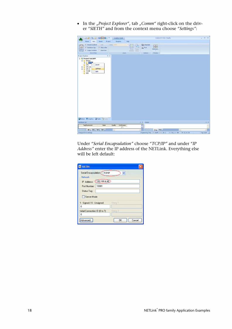
• In the „Project Explorer“, tab „Comm“ right-click on the driv-er “SIETH” and from the context menu choose “Settings”:
Under “Serial Encapsulation” choose “TCP/IP” and under “IP Address” enter the IP address of the NETLink. Everything else will be left default:
NETLink® PRO family Application Examples 19
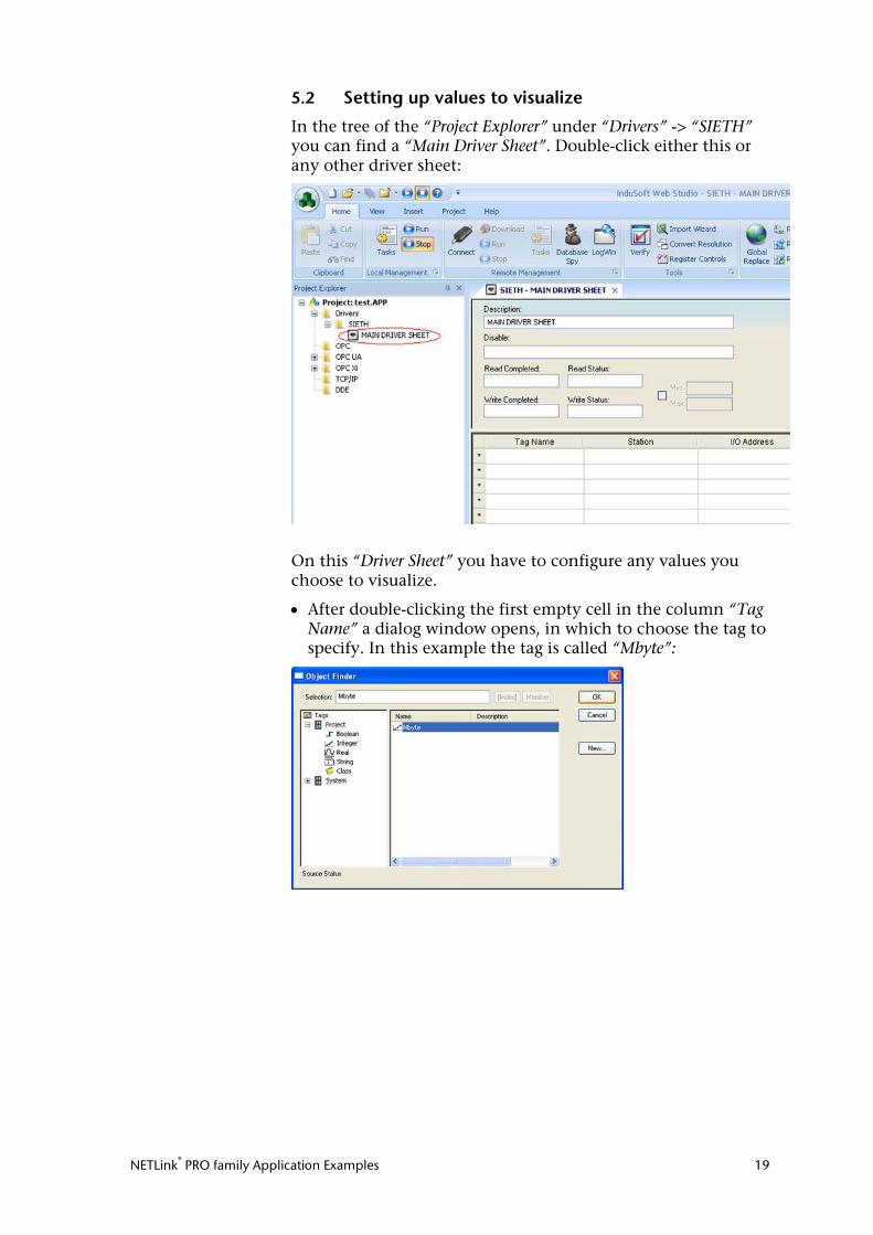
5.2 Setting up values to visualize
In the tree of the “Project Explorer” under “Drivers” -> “SIETH” you can find a “Main Driver Sheet”. Double-click either this or any other driver sheet:
On this “Driver Sheet” you have to configure any values you choose to visualize.
• After double-clicking the first empty cell in the column “Tag Name” a dialog window opens, in which to choose the tag to specify. In this example the tag is called “Mbyte”:
NETLink® PRO family Application Examples 20
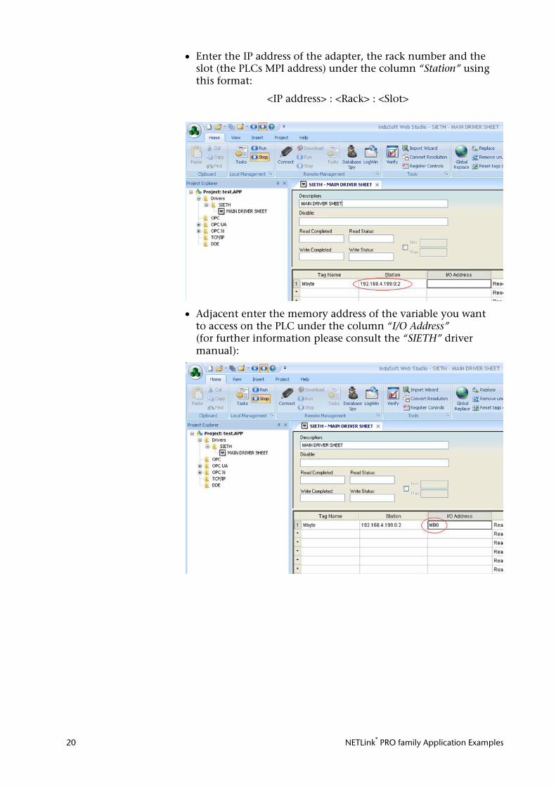
• Enter the IP address of the adapter, the rack number and the slot (the PLCs MPI address) under the column “Station” using this format:
<IP address> : <Rack> : <Slot>
• Adjacent enter the memory address of the variable you want to access on the PLC under the column “I/O Address” (for further information please consult the “SIETH” driver manual):
NETLink® PRO family Application Examples 21
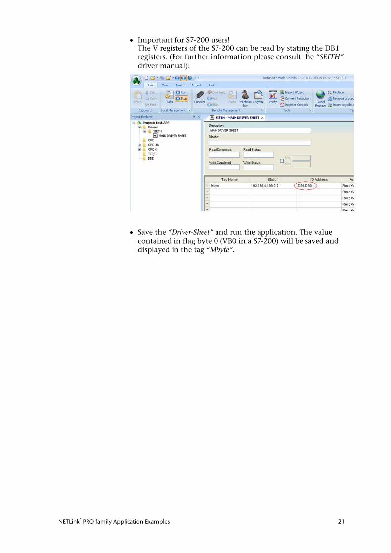
• Important for S7-200 users! The V registers of the S7-200 can be read by stating the DB1 registers. (For further information please consult the “SEITH” driver manual):
• Save the “Driver-Sheet” and run the application. The value contained in flag byte 0 (VB0 in a S7-200) will be saved and displayed in the tag “Mbyte”.
NETLink® PRO family Application Examples 22
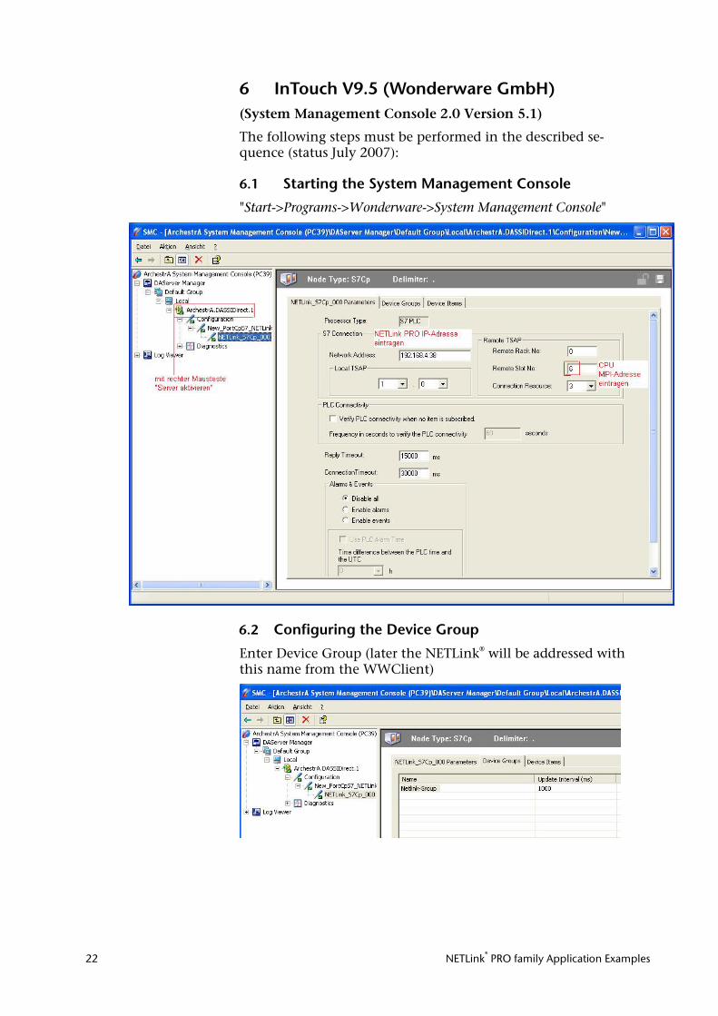
6 InTouch V9.5 (Wonderware GmbH) (System Management Console 2.0 Version 5.1)
The following steps must be performed in the described se-quence (status July 2007):
6.1 Starting the System Management Console
"Start->Programs->Wonderware->System Management Console"
6.2 Configuring the Device Group
Enter Device Group (later the NETLink® will be addressed with this name from the WWClient)
NETLink® PRO family Application Examples 23
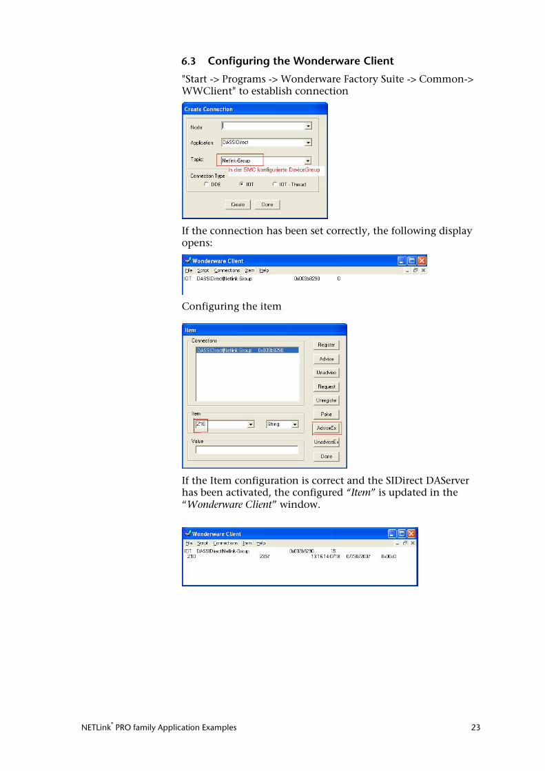
6.3 Configuring the Wonderware Client
"Start -> Programs -> Wonderware Factory Suite -> Common-> WWClient" to establish connection
If the connection has been set correctly, the following display opens:
Configuring the item
If the Item configuration is correct and the SIDirect DAServer has been activated, the configured “Item” is updated in the “Wonderware Client” window.
NETLink® PRO family Application Examples 24
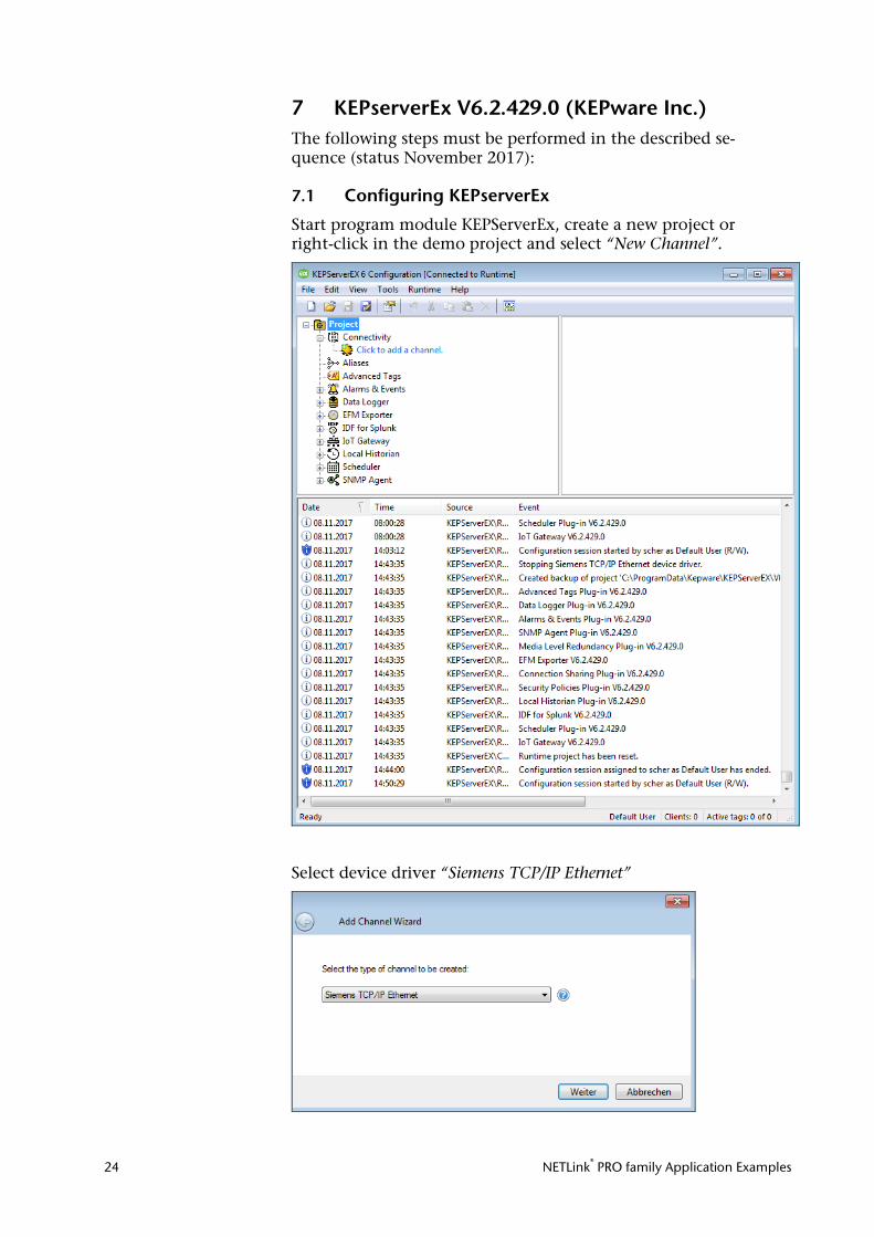
7 KEPserverEx V6.2.429.0 (KEPware Inc.) The following steps must be performed in the described se-quence (status November 2017):
7.1 Configuring KEPserverEx
Start program module KEPServerEx, create a new project or right-click in the demo project and select “New Channel”.
Select device driver “Siemens TCP/IP Ethernet”

NETLink® PRO family Application Examples 25
Enter a new name or leave the existing one and “Continue”
Select the computer’s own network card
Leave default optimizations and confirm with “Continue”.
NETLink® PRO family Application Examples 26
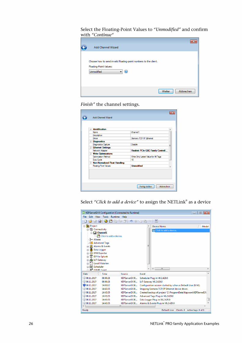
Select the Floating-Point Values to “Unmodified” and confirm with “Continue“
Finish” the channel settings.
Select “Click to add a device” to assign the NETLink® as a device
NETLink® PRO family Application Examples 27
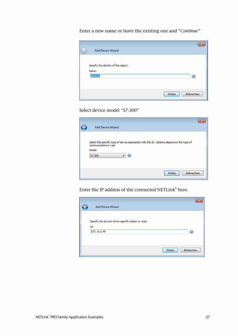
Enter a new name or leave the existing one and “Continue”
Select device model “S7-300”
Enter the IP address of the connected NETLink® here.
NETLink® PRO family Application Examples 28
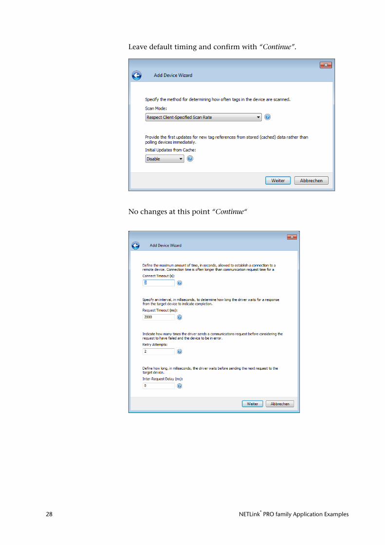
Leave default timing and confirm with “Continue”.
No changes at this point “Continue“
NETLink® PRO family Application Examples 29
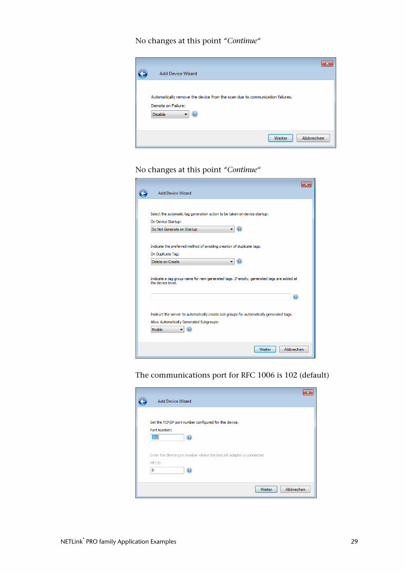
No changes at this point “Continue“
No changes at this point “Continue“
The communications port for RFC 1006 is 102 (default)
NETLink® PRO family Application Examples 30
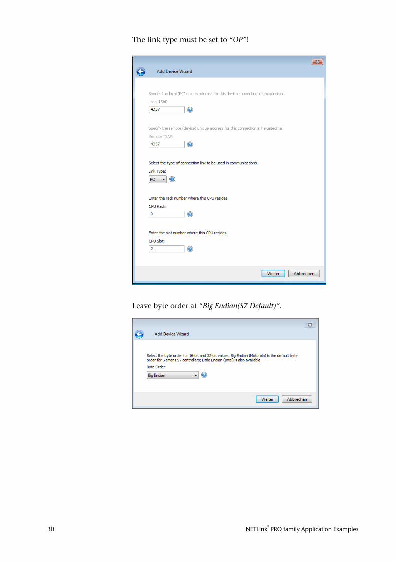
The link type must be set to “OP”!
Leave byte order at “Big Endian(S7 Default)”.
NETLink® PRO family Application Examples 31
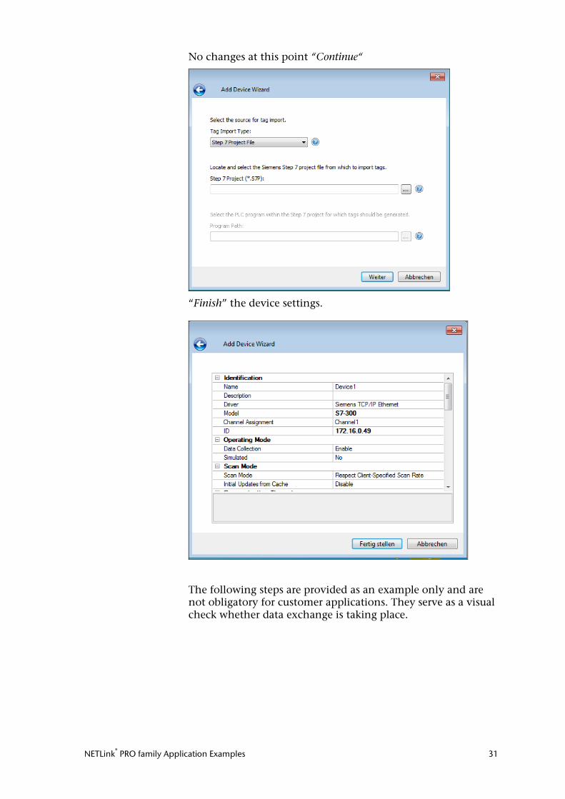
No changes at this point “Continue“
“Finish” the device settings.
The following steps are provided as an example only and are not obligatory for customer applications. They serve as a visual check whether data exchange is taking place.
NETLink® PRO family Application Examples 32
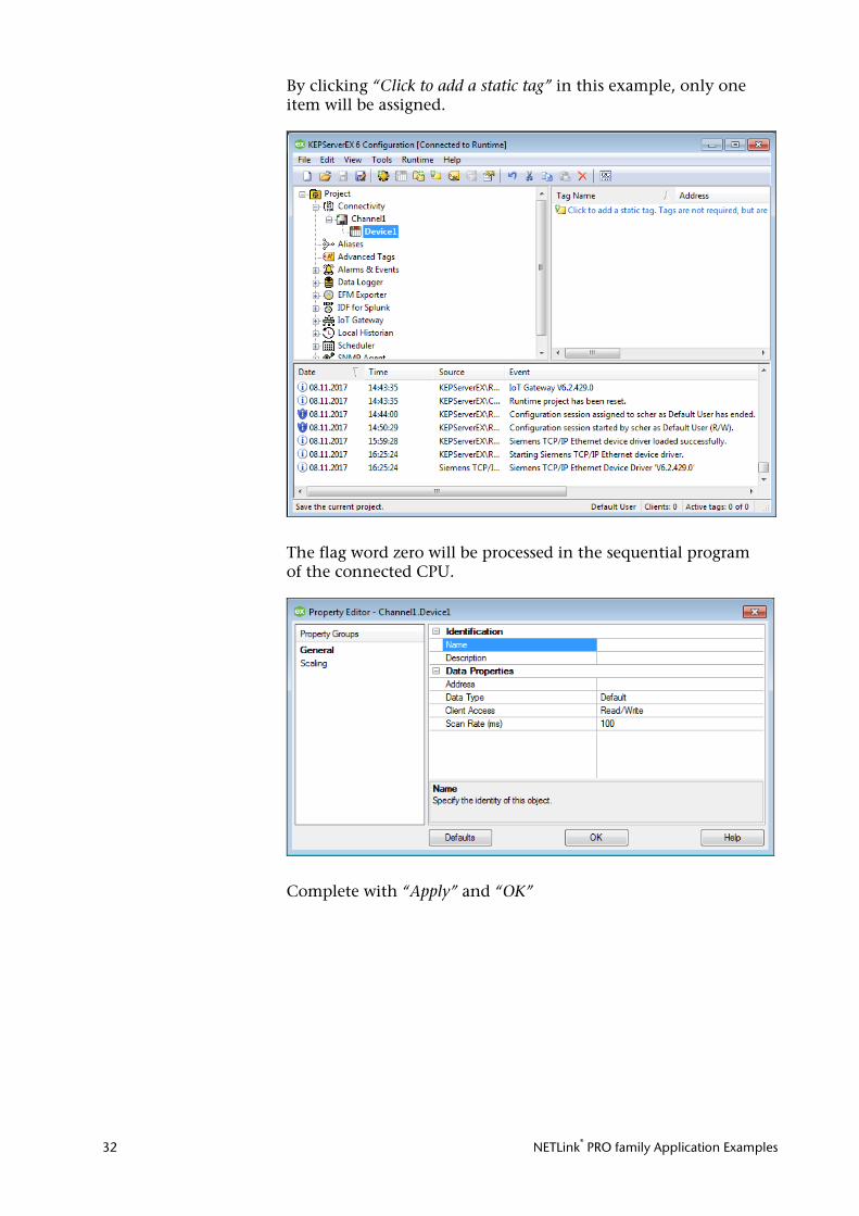
By clicking “Click to add a static tag” in this example, only one item will be assigned.
The flag word zero will be processed in the sequential program of the connected CPU.
Complete with “Apply” and “OK”
NETLink® PRO family Application Examples 33
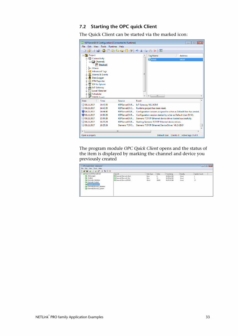
7.2 Starting the OPC quick Client
The Quick Client can be started via the marked icon:
The program module OPC Quick Client opens and the status of the item is displayed by marking the channel and device you previously created
NETLink® PRO family Application Examples 34
8 PROCON-Win V3.2 (GTI Control) The following steps must be performed in the described se-quence (Version July 2011):
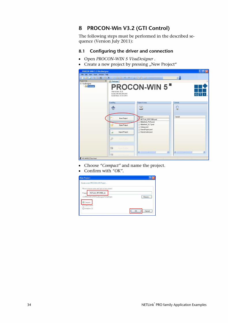
8.1 Configuring the driver and connection
• Open PROCON-WIN 5 VisuDesigner . • Create a new project by pressing „New Project“
• Choose “Compact” and name the project. • Confirm with “OK”.
NETLink® PRO family Application Examples 35
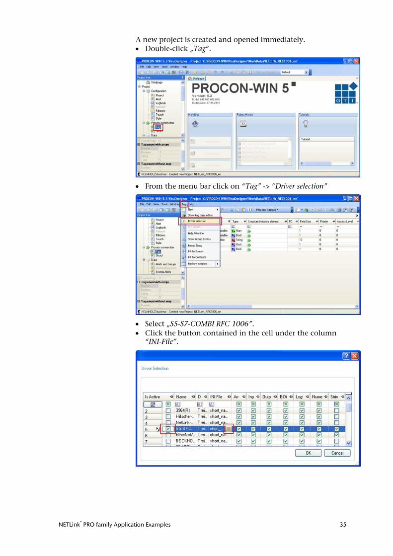
A new project is created and opened immediately. • Double-click „Tag“.
• From the menu bar click on “Tag” -> “Driver selection”
• Select „S5-S7-COMBI RFC 1006”. • Click the button contained in the cell under the column
“INI-File”.
NETLink® PRO family Application Examples 36
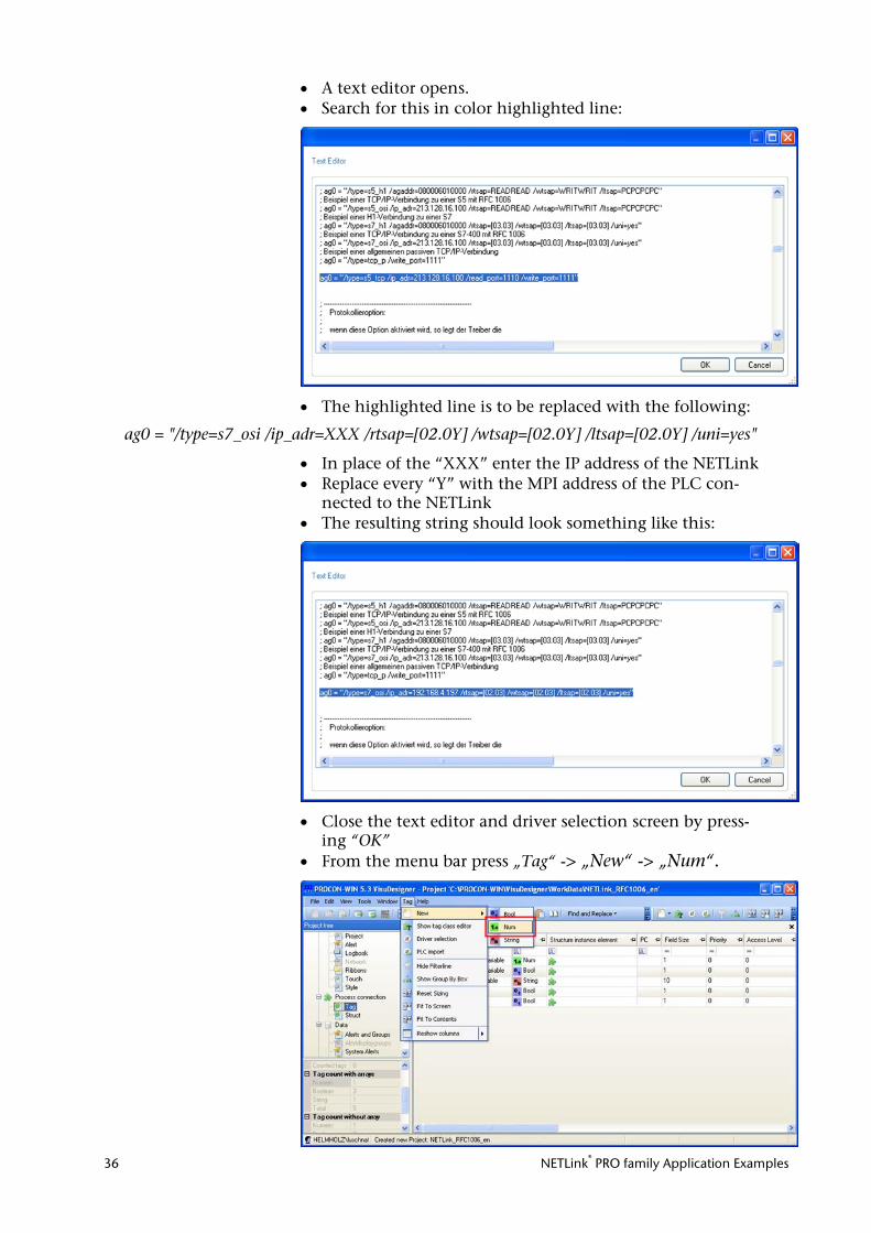
• A text editor opens. • Search for this in color highlighted line:
• The highlighted line is to be replaced with the following:
ag0 = "/type=s7_osi /ip_adr=XXX /rtsap=[02.0Y] /wtsap=[02.0Y] /ltsap=[02.0Y] /uni=yes"
• In place of the “XXX” enter the IP address of the NETLink • Replace every “Y” with the MPI address of the PLC con-
nected to the NETLink • The resulting string should look something like this:
• Close the text editor and driver selection screen by press-ing “OK”
• From the menu bar press „Tag“ -> „New“ -> „Num“.
NETLink® PRO family Application Examples 37
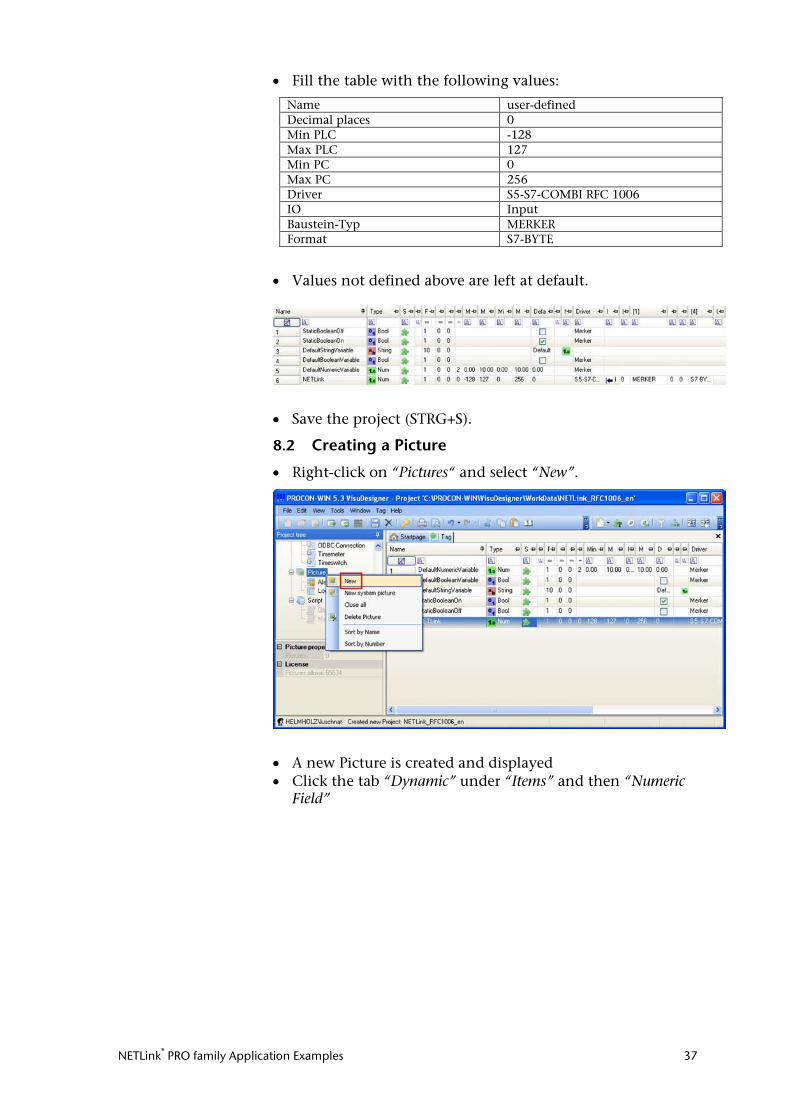
• Fill the table with the following values:
Name user-defined Decimal places 0 Min PLC -128 Max PLC 127 Min PC 0 Max PC 256 Driver S5-S7-COMBI RFC 1006 IO Input Baustein-Typ MERKER Format S7-BYTE
• Values not defined above are left at default.
• Save the project (STRG+S).
8.2 Creating a Picture
• Right-click on “Pictures“ and select “New”.
• A new Picture is created and displayed • Click the tab “Dynamic” under “Items” and then “Numeric
Field”
NETLink® PRO family Application Examples 38
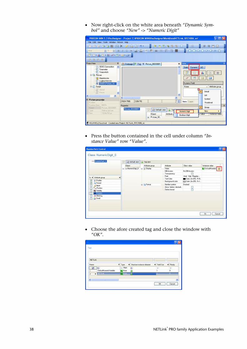
• Now right-click on the white area beneath “Dynamic Sym-bol” and choose “New” -> “Numeric Digit”
• Press the button contained in the cell under column “In-stance Value” row “Value”.
• Choose the afore created tag and close the window with “OK”.
NETLink® PRO family Application Examples 39
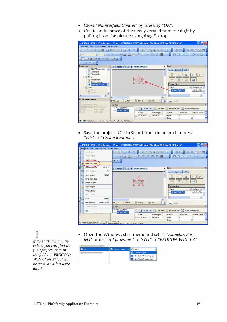
• Close “Numberfield Control” by pressing “OK”. • Create an instance of the newly created numeric digit by
pulling it on the picture using drag & drop.
• Save the project (CTRL+S) and from the menu bar press “File” -> “Create Runtime”.
• Open the Windows start menu and select “Aktuelles Pro-jekt” under “All programs” -> “GTI” -> “PROCON-WIN 5.3”
If no start menu entry exists, you can find the file “projects.pcs” in the folder “\PROCON\ WIN\Projects”. It can be opened with a texte-ditor!
NETLink® PRO family Application Examples 40
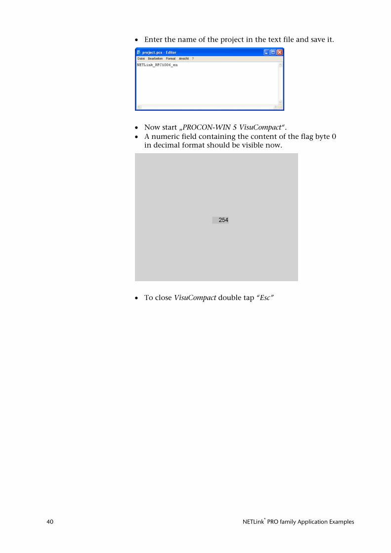
• Enter the name of the project in the text file and save it.
• Now start „PROCON-WIN 5 VisuCompact“. • A numeric field containing the content of the flag byte 0
in decimal format should be visible now.
• To close VisuCompact double tap “Esc”
NETLink® PRO family Application Examples 41
9 VisAM Win32 (VISAM GmbH) The following steps must be performed in the described se-quence (status May 2008):
9.1 Configuring VisAM Win 32
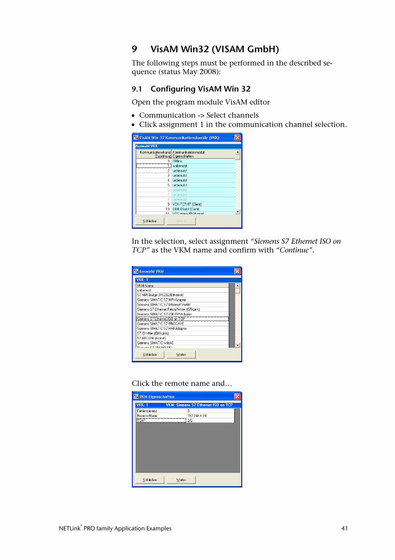
Open the program module VisAM editor
• Communication -> Select channels • Click assignment 1 in the communication channel selection.
In the selection, select assignment “Siemens S7 Ethernet ISO on TCP” as the VKM name and confirm with “Continue”.
Click the remote name and…
NETLink® PRO family Application Examples 42
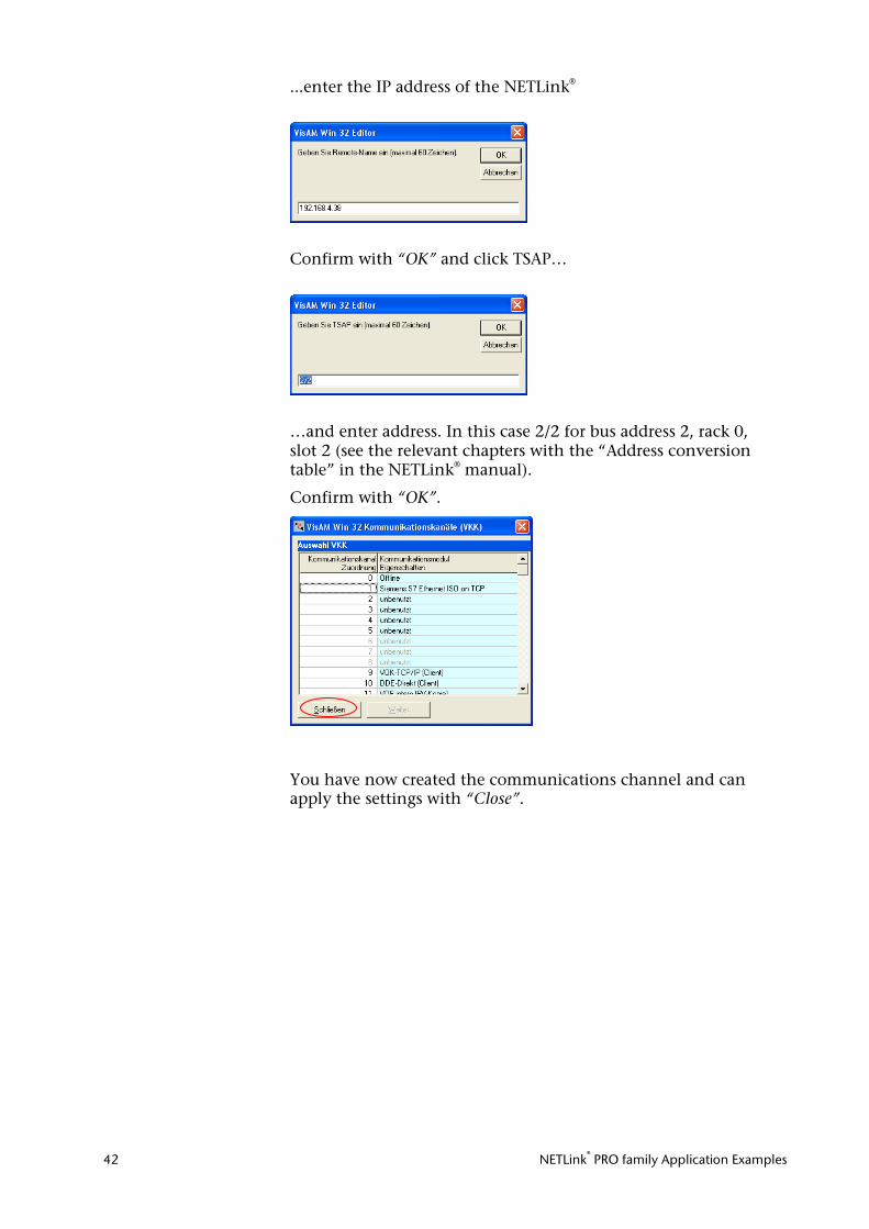
...enter the IP address of the NETLink®
Confirm with “OK” and click TSAP…
…and enter address. In this case 2/2 for bus address 2, rack 0, slot 2 (see the relevant chapters with the “Address conversion table” in the NETLink® manual).
Confirm with “OK”.
You have now created the communications channel and can apply the settings with “Close”.
NETLink® PRO family Application Examples 43
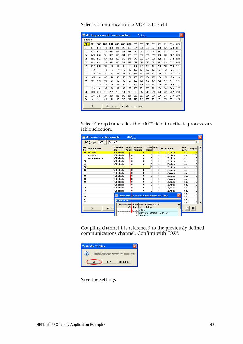
Select Communication -> VDF Data Field
Select Group 0 and click the “000" field to activate process var-iable selection.
Coupling channel 1 is referenced to the previously defined communications channel. Confirm with “OK”.
Save the settings.
NETLink® PRO family Application Examples 44
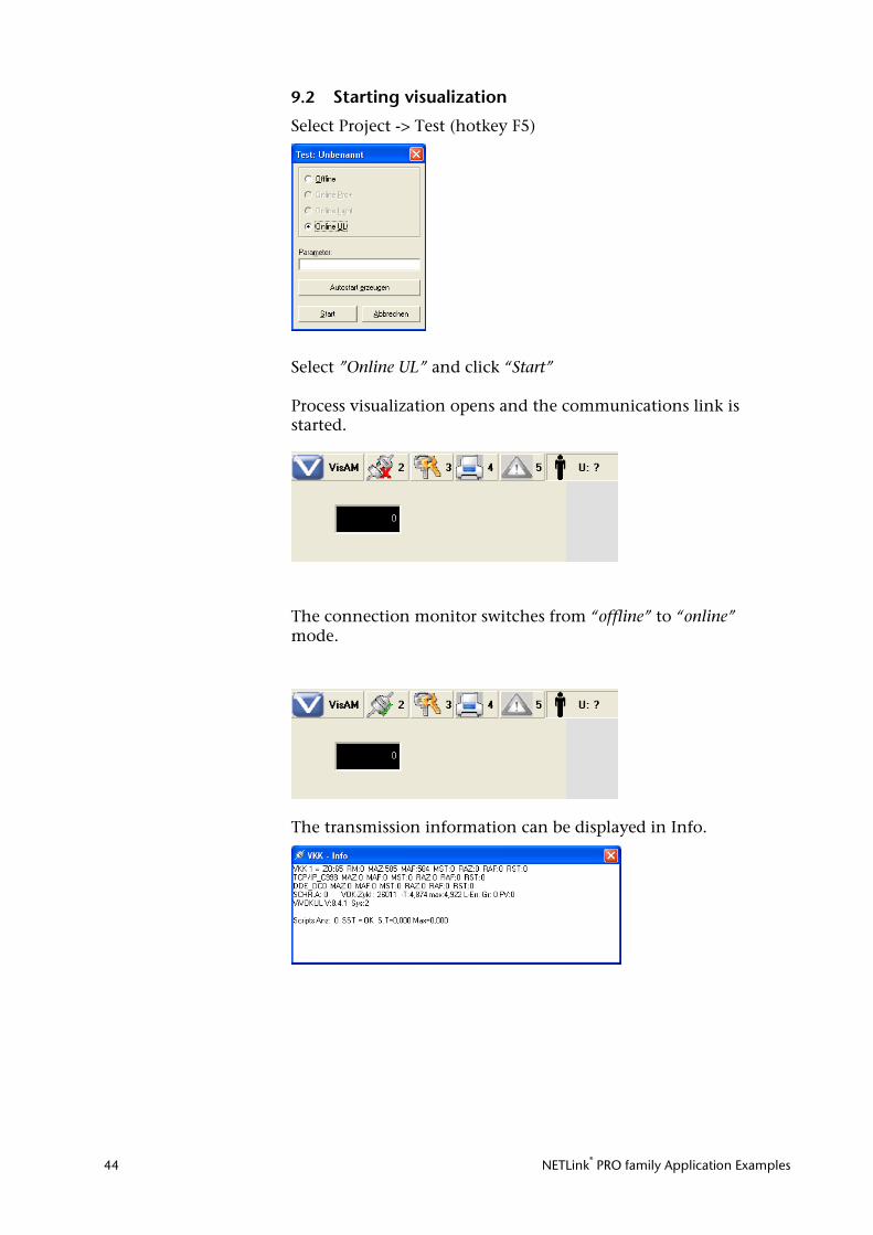
9.2 Starting visualization
Select Project -> Test (hotkey F5)
Select ”Online UL” and click “Start” Process visualization opens and the communications link is started.
The connection monitor switches from “offline” to “online” mode.
The transmission information can be displayed in Info.
NETLink® PRO family Application Examples 45
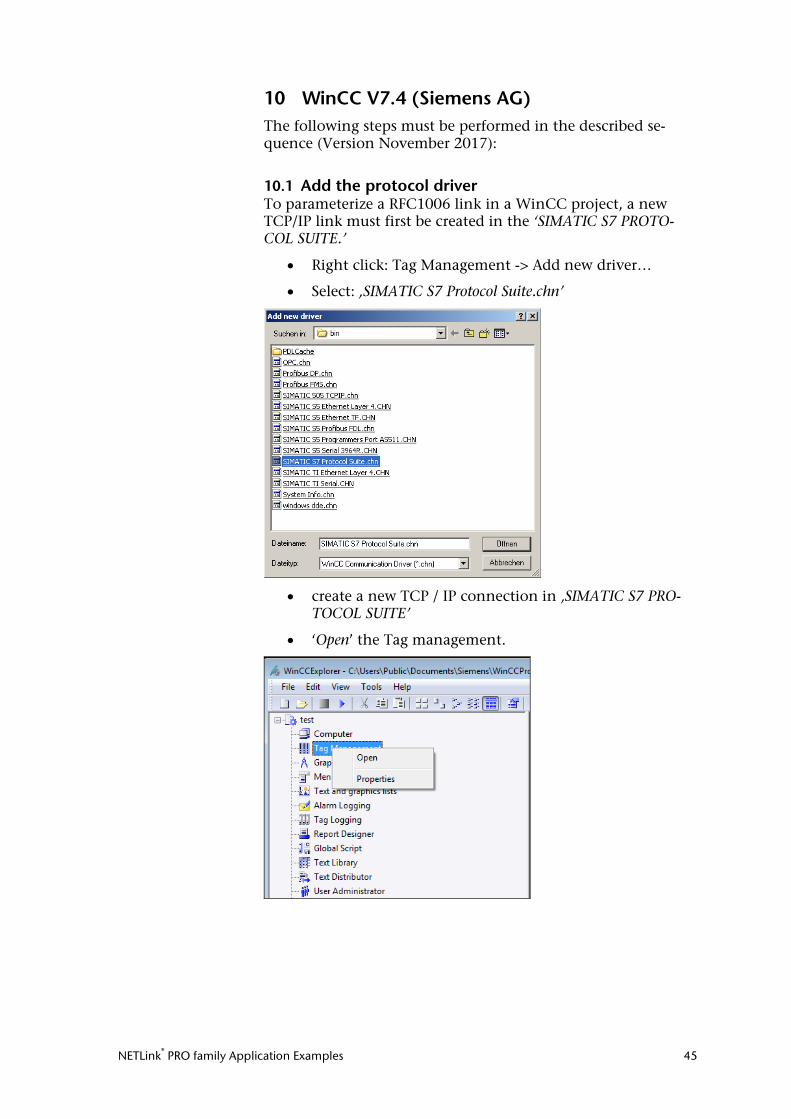
10 WinCC V7.4 (Siemens AG) The following steps must be performed in the described se-quence (Version November 2017):
10.1 Add the protocol driver To parameterize a RFC1006 link in a WinCC project, a new TCP/IP link must first be created in the ‘SIMATIC S7 PROTO-COL SUITE.’
• Right click: Tag Management -> Add new driver…
• Select: ,SIMATIC S7 Protocol Suite.chn’
• create a new TCP / IP connection in ‚SIMATIC S7 PRO-TOCOL SUITE’
• ‘Open’ the Tag management.
NETLink® PRO family Application Examples 46
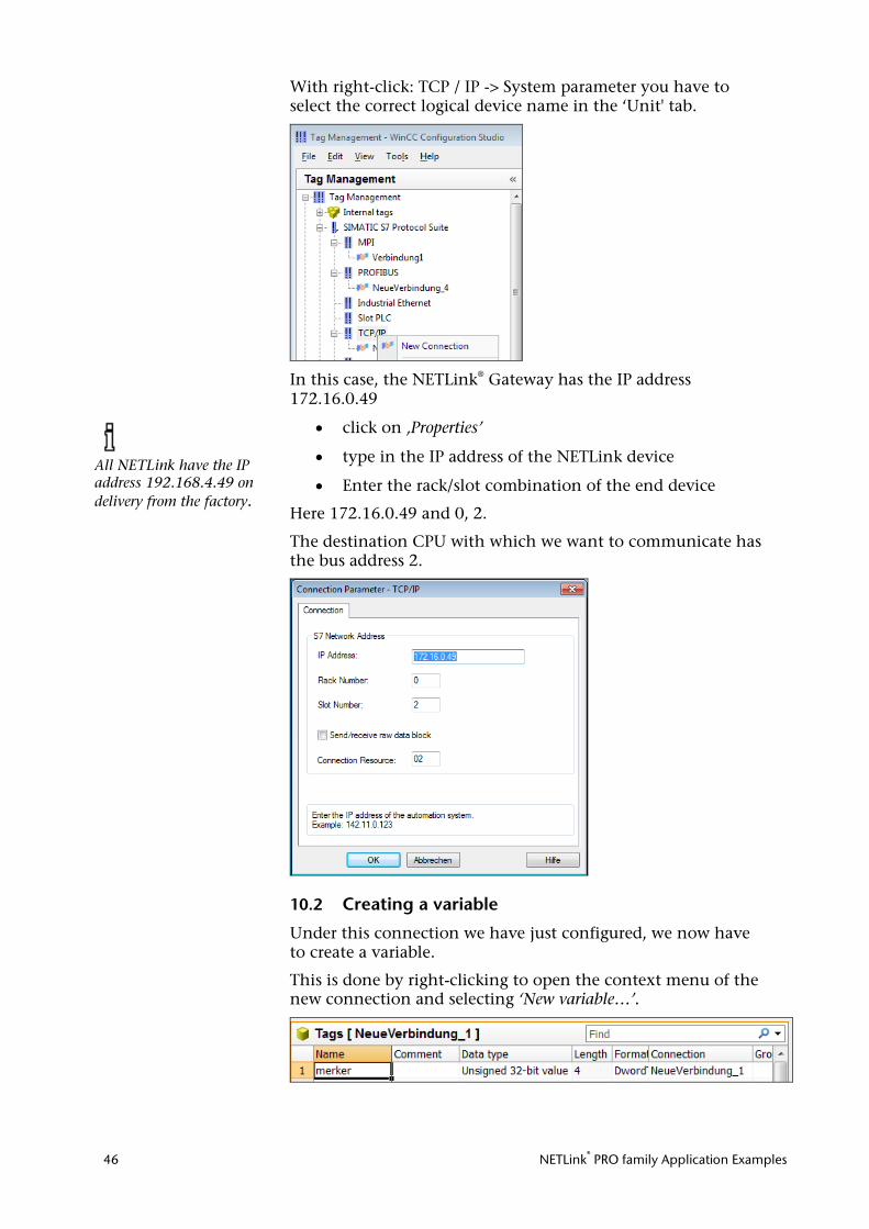
With right-click: TCP / IP -> System parameter you have to select the correct logical device name in the ‘Unit' tab.
In this case, the NETLink® Gateway has the IP address 172.16.0.49
• click on ‚Properties’
• type in the IP address of the NETLink device
• Enter the rack/slot combination of the end device
Here 172.16.0.49 and 0, 2.
The destination CPU with which we want to communicate has the bus address 2.
10.2 Creating a variable
Under this connection we have just configured, we now have to create a variable.
This is done by right-clicking to open the context menu of the new connection and selecting ‘New variable…’.
All NETLink have the IP address 192.168.4.49 on delivery from the factory.
NETLink® PRO family Application Examples 47
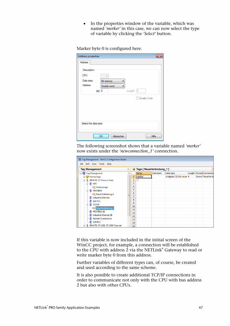
• In the properties window of the variable, which was named ‘merker’ in this case, we can now select the type of variable by clicking the ‘Select’ button.
Marker byte 0 is configured here.
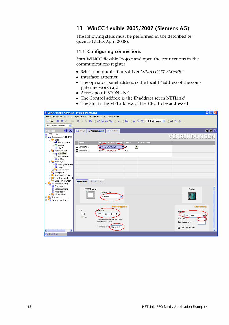
The following screenshot shows that a variable named ‘merker’ now exists under the ‘newconnection_1’ connection.
If this variable is now included in the initial screen of the WinCC project, for example, a connection will be established to the CPU with address 2 via the NETLink® Gateway to read or write marker byte 0 from this address.
Further variables of different types can, of course, be created and used according to the same scheme.
It is also possible to create additional TCP/IP connections in order to communicate not only with the CPU with bus address 2 but also with other CPUs.
NETLink® PRO family Application Examples 48
11 WinCC flexible 2005/2007 (Siemens AG) The following steps must be performed in the described se-quence (status April 2008):
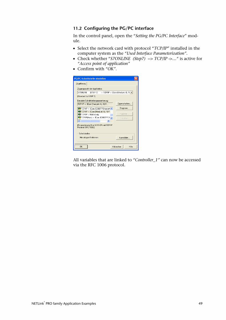
11.1 Configuring connections
Start WINCC flexible Project and open the connections in the communications register:
• Select communications driver "SIMATIC S7 300/400" • Interface: Ethernet • The operator panel address is the local IP address of the com-
puter network card • Access point: S7ONLINE • The Control address is the IP address set in NETLink® • The Slot is the MPI address of the CPU to be addressed
NETLink® PRO family Application Examples 49
11.2 Configuring the PG/PC interface
In the control panel, open the “Setting the PG/PC Interface” mod-ule.
• Select the network card with protocol “TCP/IP” installed in the computer system as the “Used Interface Parameterization”.
• Check whether “S7ONLINE (Step7) --> TCP/IP ->…“ is active for “Access point of application”
• Confirm with “OK”.
All variables that are linked to “Controller_1” can now be accessed via the RFC 1006 protocol.
NETLink® PRO family Application Examples 50
12 ZenOn V6.2 (COPA-DATA) The following steps must be performed in the described sequence (status August 2007):
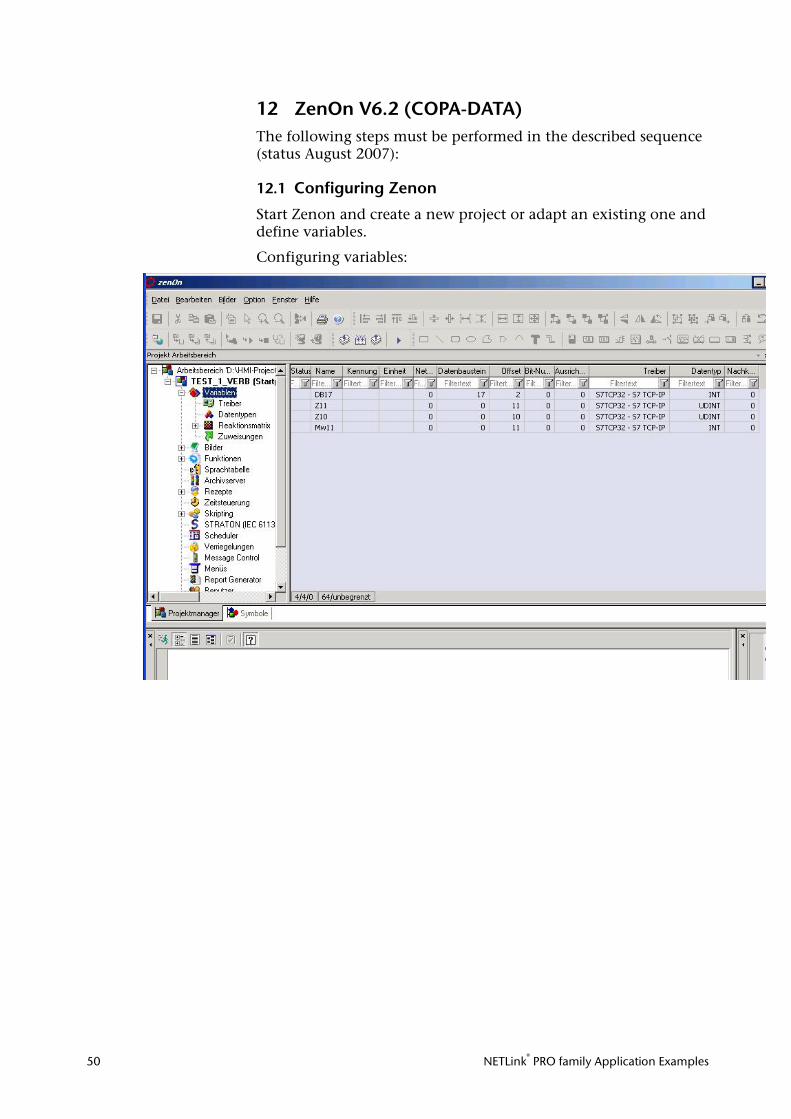
12.1 Configuring Zenon
Start Zenon and create a new project or adapt an existing one and define variables.
Configuring variables:
NETLink® PRO family Application Examples 51
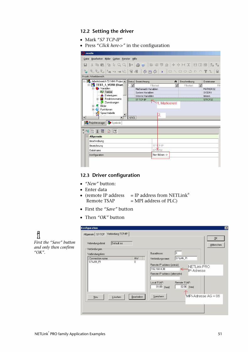
12.2 Setting the driver
• Mark “S7 TCP-IP” • Press “Click here->” in the configuration
12.3 Driver configuration
• “New” button: • Enter data • (remote IP address = IP address from NETLink®
Remote TSAP = MPI address of PLC)
• First the “Save” button
• Then “OK” button
First the “Save” button and only then confirm “OK”.
NETLink® PRO family Application Examples 52
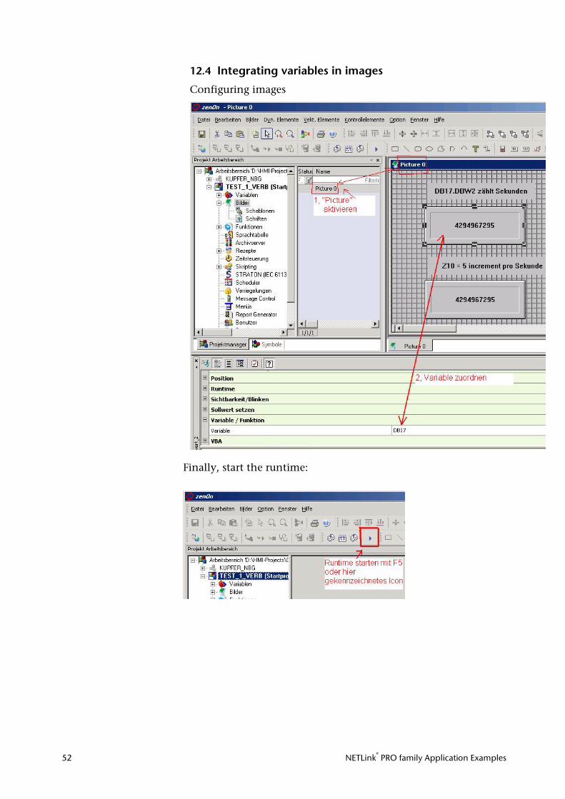
12.4 Integrating variables in images
Configuring images
Finally, start the runtime:
NETLink® PRO family Application Examples 53
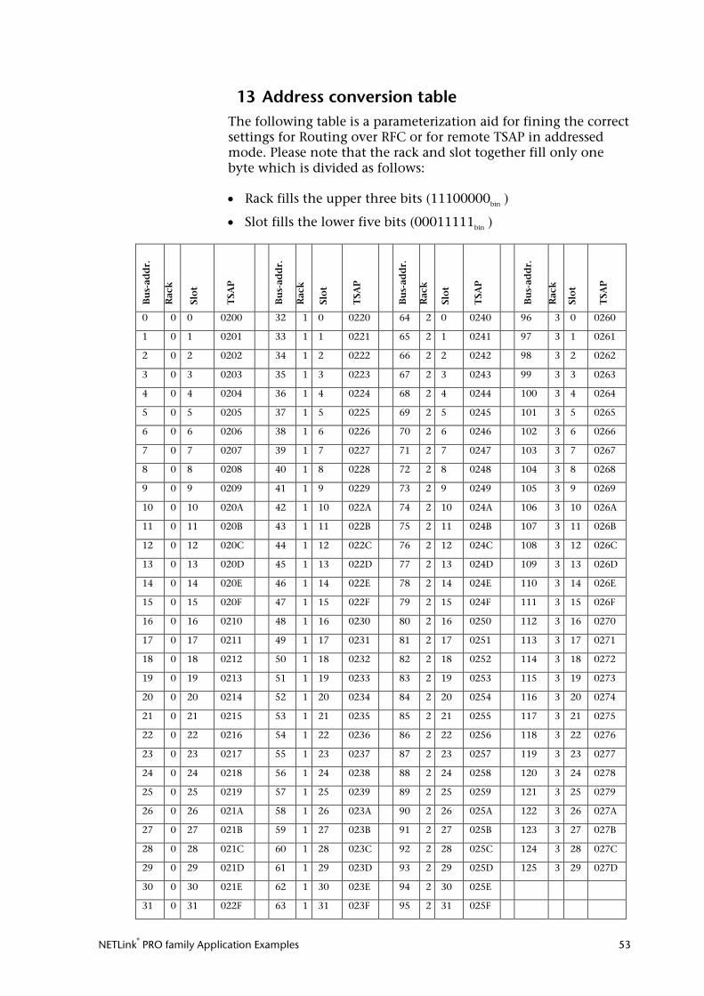
13 Address conversion table The following table is a parameterization aid for fining the correct settings for Routing over RFC or for remote TSAP in addressed mode. Please note that the rack and slot together fill only one byte which is divided as follows:
• Rack fills the upper three bits (11100000bin )
• Slot fills the lower five bits (00011111bin )
Bu
s-ad
dr.
Rac
k
Slo
t
TSA
P
Bu
s-ad
dr.
Rac
k
Slo
t
TSA
P
Bu
s-ad
dr.
Rac
k
Slo
t
TSA
P
Bu
s-ad
dr.
Rac
k
Slo
t
TSA
P
0 0 0 0200 32 1 0 0220 64 2 0 0240 96 3 0 0260
1 0 1 0201 33 1 1 0221 65 2 1 0241 97 3 1 0261
2 0 2 0202 34 1 2 0222 66 2 2 0242 98 3 2 0262
3 0 3 0203 35 1 3 0223 67 2 3 0243 99 3 3 0263
4 0 4 0204 36 1 4 0224 68 2 4 0244 100 3 4 0264
5 0 5 0205 37 1 5 0225 69 2 5 0245 101 3 5 0265
6 0 6 0206 38 1 6 0226 70 2 6 0246 102 3 6 0266
7 0 7 0207 39 1 7 0227 71 2 7 0247 103 3 7 0267
8 0 8 0208 40 1 8 0228 72 2 8 0248 104 3 8 0268
9 0 9 0209 41 1 9 0229 73 2 9 0249 105 3 9 0269
10 0 10 020A 42 1 10 022A 74 2 10 024A 106 3 10 026A
11 0 11 020B 43 1 11 022B 75 2 11 024B 107 3 11 026B
12 0 12 020C 44 1 12 022C 76 2 12 024C 108 3 12 026C
13 0 13 020D 45 1 13 022D 77 2 13 024D 109 3 13 026D
14 0 14 020E 46 1 14 022E 78 2 14 024E 110 3 14 026E
15 0 15 020F 47 1 15 022F 79 2 15 024F 111 3 15 026F
16 0 16 0210 48 1 16 0230 80 2 16 0250 112 3 16 0270
17 0 17 0211 49 1 17 0231 81 2 17 0251 113 3 17 0271
18 0 18 0212 50 1 18 0232 82 2 18 0252 114 3 18 0272
19 0 19 0213 51 1 19 0233 83 2 19 0253 115 3 19 0273
20 0 20 0214 52 1 20 0234 84 2 20 0254 116 3 20 0274
21 0 21 0215 53 1 21 0235 85 2 21 0255 117 3 21 0275
22 0 22 0216 54 1 22 0236 86 2 22 0256 118 3 22 0276
23 0 23 0217 55 1 23 0237 87 2 23 0257 119 3 23 0277
24 0 24 0218 56 1 24 0238 88 2 24 0258 120 3 24 0278
25 0 25 0219 57 1 25 0239 89 2 25 0259 121 3 25 0279
26 0 26 021A 58 1 26 023A 90 2 26 025A 122 3 26 027A
27 0 27 021B 59 1 27 023B 91 2 27 025B 123 3 27 027B
28 0 28 021C 60 1 28 023C 92 2 28 025C 124 3 28 027C
29 0 29 021D 61 1 29 023D 93 2 29 025D 125 3 29 027D
30 0 30 021E 62 1 30 023E 94 2 30 025E
31 0 31 022F 63 1 31 023F 95 2 31 025F
NETLink® PRO family Application Examples 54
14 Troubleshooting The points described here show some typical errors that can occur when using the RFC 1006 function.
Please also refer to the descriptions for troubleshooting in the ac-cordant NETLink® manual!
If a problem is not described here and this manual does not pro-vide any information on how to remedy it, the support of Helm-holz GmbH & Co.KG will gladly help you to solve the problem.
Q: How can I specify the target station(s) for RFC 1006 communi-cations in WinCC by using the Rack/Slot fields?
A: Since the RFC protocol does not have a default entry for speci-fying the PROFIBUS/MPI address of a target station (PLC), you will have to use the 2 byte-long TSAP field. The first byte of the TSAP ID is the rack value, while the second is the slot value (the value range for the slot field will often have a maximum value of 31, e.g., in WinCC).
This is why the NETLink unit will have to evaluate both of the TSAP field bytes in order to determine the address of the target station.
Scenario 1: Your application allows slot field values of up to 126
---> You will have to enter “0” into the Rack field and the PROFIBUS address of your CPU into the Slot field.
Scenario 2: Your application only allows slot field values of up to 31
---> You will have to enter a 32x multiplier into the Rack field and the missing remainder of the PROFIBUS address into the Slot field.
Address assignments using the Rack and Slot input fields:
Example 1: Entry for address 17 ≙ Calculation: (0* 32 + 17)
Example 2: Entry for address 34 ≙ Calculation: (1* 32 + 2)
Example 3: Entry for address 69 ≙ Calculation: (2* 32 + 5)
Q: Why do I get an address conflict when trying to communicate via Step 7 with the RFC 1006 mode activated even though the sta-tion-related address has been adapted in the driver?
A: You have probably changed your own address in the Web in-terface (default = 0). The NETLink® automatically tries to go online with this address on the bus in RFC mode. Conflicts will occur if another node uses the same address. In this case, the al-tered entry in Step 7 is ignored. Check the status of the active sta-tions in the Web interface.
Q: How is a firmware update performed in a NETLink® adapter?
A: The following steps must be performed:
1) Download the up-do-date “SHTools” software from the Com-pany Helmholz web site and install this on your computer.
A firmware update on the NETLink® WLAN must always be per-formed via the network socket.
NETLink® PRO family Application Examples 55
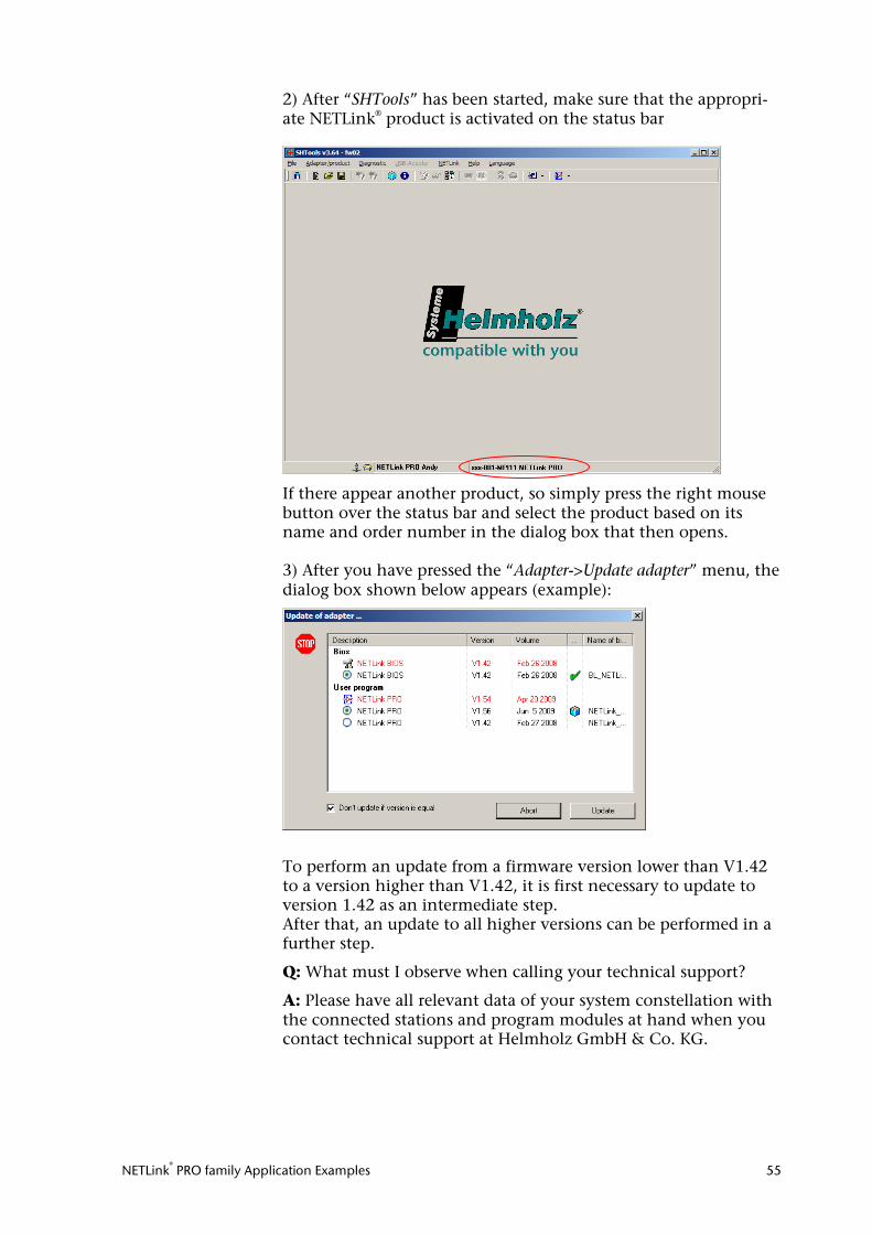
2) After “SHTools” has been started, make sure that the appropri-ate NETLink® product is activated on the status bar
If there appear another product, so simply press the right mouse button over the status bar and select the product based on its name and order number in the dialog box that then opens. 3) After you have pressed the “Adapter->Update adapter” menu, the dialog box shown below appears (example):
To perform an update from a firmware version lower than V1.42 to a version higher than V1.42, it is first necessary to update to version 1.42 as an intermediate step. After that, an update to all higher versions can be performed in a further step.
Q: What must I observe when calling your technical support?
A: Please have all relevant data of your system constellation with the connected stations and program modules at hand when you contact technical support at Helmholz GmbH & Co. KG.
NETLink® PRO family Application Examples 56
15 Directory of Sources
INAT-OPC-Server (http://www.inat.de/index.php?18&backPID=18&tt_products_sof=236)
InduSoft Web Studio v7.0 (http://www.indusoft.com/indusoftart.php?catid=1&name=IWS/webstudio)
InTouch V9.5 (Wonderware GmbH) (http://global.wonderware.com/EN/Pages/WonderwareInTouch-HMI.aspx)
KEPserverEx V5.4.135.0 (http://www.kepware.com/Products/OPC_Servers.html)
PROCON-Win V5.3 (http://www.gti.de/index.php?id=45)
S7/S5 OPC-Server (http://www.helmholz.de/prod.d,18_30_34.html?p_id=39)
VisAM Win32 (http://www.visam.de/03_produkte/visam/index.php)
WINCC V7.0 (http://www.automation.siemens.com/mcms/human-machine-in-terface/de/visualisierungssoftware/scada-wincc/Seiten/Default.aspx)
WinCC flexible 2005/2007 (http://www.automation.siemens.com/hmi/html_00/products/software/wincc-flexible/index.htm)
ZenOn V6.2 (http://www.copadata.at/de/ger/home.html)